Embed Size (px)
Citation preview

P.O. BOX 729 TERRELL, TEXAS 75160
214-515-5400 / 800-776-2349
ASY-046 PAGE1 OF 15 REV. 02
10/18/06 AJB ECN#500000002553
MAXILINE GONDOLA AND WALL GENERAL ASSEMBLYNOTE! This publication is intended to be a generic installation instruction for Madix gondola and wall shelving, and may possibly be subject
to change as required by the local building codes. Consult the building inspection department at the job site.
GONDOLA
WALL
IMPORTANT! When unloading, stack all boxes...
1. WITH THE LABELS VISIBLE.
2. WITH THE SAME DESCRIPTION TOGETHER.
3. WITH THE SAME PART NUMBER TOGETHER.
NOTE!
THE STANDARD PRODUCTS LISTED BELOW
WILL ALTER THE INSTALLATION PROCEDURE SHOWN.
Specific instructions covering any products listed below,
if ordered, are included with this document package.
Refer to them prior to beginning installation
since your procedure will be altered.
END MERCHANDISER ...........ASY-652
CANOPIES..........ASY-092
TELESCOPING UPRIGHTS..........ASY-027
BOX CORNER..........ASY-098
METAL END FLAT..........ASY-269
INSIDE CORNER..........ASY-062
OPEN BACK STIFFENER..........ASY-042
OUTSIDE CORNER..........ASY-059
FLOOR ANCHORS..........ASY-357
WIRE GRID BACKS..........ASY-328
OUTSIDE MOUNT END
MERCHANDISER..........ASY-064
TRIPLE BACK SYSTEM..........ASY-325
READ AND UNDERSTAND THIS DOCUMENT BEFORE PROCEEDING TO
INSTALL SHELVING. SPECIAL ITEMS THROUGHOUT ARE DENOTED WITH:
CAUTION! IMPORTANT! WARNING!!

P.O. BOX 729 TERRELL, TEXAS 75160
214-515-5400 / 800-776-2349
ASY-046 PAGE2 OF 15 REV. 02
10/18/06 AJB ECN#500000002553
PALLET #
MFQ ORDER #
MADIX ORDER #
CARRIER
ITEMS ON PALLET
PALLET LABEL LAYOUT
QUANTITY ON
PALLET
MATERIAL # MATERIAL
DESCRIPTION
MATERIAL
COLOR(S)
SHIP
DATECUSTOMER
P.O.
PALLET WEIGHT
SHIP TO ADDRESS
PACK TYPE
REQUEST
TL = TRUCK LOAD
LTL = LESS THAN
TRUCK LOAD
THE CUSTOMER
123 FAKE STREET
P.O. BOX 729 TERRELL, TEXAS 75160
214-515-5400 / 800-776-2349
ASY-046 PAGE 3 OF 15 REV. 02
10/18/06 AJB ECN#500000002553
Install all shelving and/or fixtures as described in installation instruction.
Shelving and components should ONLY be installed by trained personnel
who have read and understand these instructions. Failure to to do so may
result in product damage or personal injury.
Do not exceed the maximum load capacities as outlined under all headings
related to Load Limits or Capacities in this document.
Never use damaged parts.
Install and use components only as directed.
Do not combine Madix products with non-Madix products.
Always install kickplates (KP-(nw)) to retain the structural integrity of the
shelving. Kickplates must be installed correctly!
Do not hang shelves, peg hooks or other accessories on the side of a
fixture that does not have base shoes (BS) installed.
Do not hang shelving, peg hooks or other accessories that exceed the depth
of the base on a gondola or wall.
All components that require trim, such as uprights (BU) and base shoes (BS)
should have trim installed.
Never expose any sharp or pointed edges to shoppers or employees.
Do not climb or stand on shelving.
Provide safe access to all levels of shelving according to OSHA regulations.
Do not move assembled unit.
Do not rearrange shelving while merchandised.
Do not lean heavy items against shelving.
All end panels (EP) and other panels for merchandising or aesthetics must
have bases in order to direct traffic away from protrusions.
WARNING!!
!
!
!
READ BEFORE ASSEMBLY - FOR YOUR SAFETY!
POST THIS ENTIRE PAGE IN A CONSPICUOUS PLACE, CLEARLY VISIBLE TO ALL STORE PERSONNEL
TM
TERRELL, TX 800-776-2349 www.madixinc.com
IMPORTANT INSTRUCTIONS FOR CLEANING
MADIX METAL SHELVING:
When necessary to clean Madix shelving, use of a non-abrasive
mild detergent and warm water, followed by thorough drying is
ideal. The use of a cloth made of a soft , white cotton material is
strongly recommended. The use of cleaning agents that contain
abrasives, bleach, or strong solvents such as ketones, ethers etc.
will result in damage to the finish. The damage is most severe
when these harsh cleaning agents are used on colors which
contain leafing aluminum pigment such as powder chrome,
silver vein and other "vein" type finishes. The aluminum in these
coatings resides at the surface of the finish and is therefore more
susceptible to damage by the harsh cleaning agents. As an
alternative to the mild detergent, cleaners with ingredients
similar to those found in products such as 409 , Fantastik, and
Simple Green can be used. CAUTION! cleaners having ingredients
similar to those found in Ajax, Borax, Bleach, Comet, etc. should be
avoided as finish damage could result.
CLEANING SHELVING:
WARNING! ALL GONDOLA AND WALL FIXTURES
EXCEEDING 96” IN HEIGHT MUST BE SECURELY ANCHORED!
SEE ASY-357 FOR PROPER ANCHORING PROCEDURES
FOR GONDOLA AND WALL!
WARNING! NEVER STACK EXTENSION UPRIGHTS (EU).
Do not exceed maximum load capacity on EU. Maximum
load capacity for EU 6” to 12“ is 250 lb per side, 13” to 18”
is 215 lb per side, 19“ to 24 “ is 160 lb per side, and 24” and
up is 100 lb per side. SEE ASY-018 FOR EU INSTALLATION.
WARNING! LOAD CAPACITY FOR PEGBOARD BACKS:
MAX 150 lbs for per side with SL lower spanner in place
MAX 300 lbs per side with HSL Heavy Duty Lower Spanner

P.O. BOX 729 TERRELL, TEXAS 75160
214-515-5400 / 800-776-2349
ASY-046 PAGE4 OF 15 REV. 02
10/18/06 AJB ECN#500000002553
LEVELER SPACING
WALL
LEVELER SPACING
GONDOLA
If the height of the upright exceeds six times the space between the upright and shoe
leveler, the system must be secured in one of the following configurations:
Secured at the top as per pg. 11 or...
For Gondolas, Base Shoe Levelers must be anchored to the floor as shown in
ASY-357
For Walls, Base Shoe Levelers AND Upright Levelers must be anchored to the floor.
UPRIGHT HEIGHT
UPRIGHT HEIGHT
BASE SHELF
DEPTH OF
12” 9 1/2” 54”
14” 11 1/2” 66”
16” 13 1/2” 78”
18” 15 1/2” 90”
20 17 1/2” 102”
22” 19 1/2” 114”
24” 21 1/2” 120”
26” 23 1/2” 138”
28” 25 1/2” 144”
30” 27 1/2” 162”
EQUALS LEVELER
SPACING OF
MAX HEIGHT
OF UNANCHORED
UPRIGHT
BASE SHELF
DEPTHS OF
12” & 12” 19” 114”
12” & 14” 21” 126”
14 & 14” 23” 138”
14” & 16” 25” 144”
16” & 16” 27” 162”
EQUALS LEVELER
SPACING OF
MAX HEIGHT
OF UNANCHORED
UPRIGHT
WALLS...
USE CHART FOR EXAMPLE ONLY:
GONDOLAS...
USE CHART FOR EXAMPLE ONLY:
FIXTURE HEIGHT TO BASE WIDTH:
BOLTING UPPER SHELVES AT THE TOP OF
FIXTURES TALLER THAN 96”...
VIEW FROM BELOW
UPPER SHELVES
!
!
ON ANY UPPER ROW OF SHELVES ON FIXTURES
TALLER THAN 96”, THE SHELVES MUST BE
BOLTED TOGETHER THROUGH THE FRONT MOST
HOLES IN THE SIDES OF THE SHELVES!
ALL UPRIGHTS 96” AND ABOVE
WILL NEED TO BE ANCHORED.!

P.O. BOX 729 TERRELL, TEXAS 75160
214-515-5400 / 800-776-2349
ASY-046 PAGE 5 OF 15 REV. 02
10/18/06 AJB ECN#500000002553
!WSRP MUST BE INSTALLED
IN ALL WALL UPRIGHTS AND ALL
UPRIGHTS ABOVE 96” FOR
GONDOLA AND WALL!
GONDOLA / WALL PARTS IDENTIFICATION...
• THE PARTS SHOWN HERE REPRESENT
A WALL, SINGLE SIDED, SECTION.
• BOTH GONDOLA AND WALL
SECTIONS USE THE SAME PARTS.
• PAGES 7-10 SHOW INSTALLATION
OF A GONDOLA, DOUBLE SIDED, FIXTURE.
P.O. BOX 729 TERRELL, TEXAS 75160
214-515-5400 / 800-776-2349
ASY-046 PAGE 6 OF 15 REV. 02
10/18/06 AJB ECN#500000002553
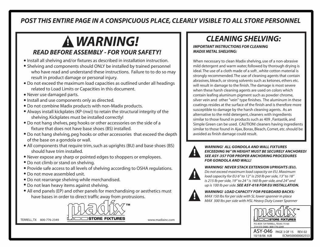
BACK PANEL IDENTIFICATION FOR GONDOLA AND WALLS
SS-
BXP- 436 35 7/8�
BP- 442 37 3/16�
60� UPRIGHT
BP- 460 55
78� UPRIGHT
SS-
BXP- 424 23 7/8�
SS-
BXP- 454 53 7/8�
BP- 442 37 3/16�
120� UPRIGHT
SS-
BXP- 430 29 7/8�
SS-
BXP- 454 53 7/8�
BP- 442 37 3/16�
126� UPRIGHT
SS-
BXP- 436 35 7/8�
SS-
BXP- 454 53 7/8�
BP- 442 37 3/16�
132� UPRIGHT
SS-
BXP- 442 41 7/8�
SS-
BXP- 454 53 7/8�
BP- 442 37 3/16�
138� UPRIGHT
SS-
BXP- 448 47 7/8�
SS-
BXP- 454 53 7/8�
BP- 442 37 3/16�
144� UPRIGHT
SS-
BXP- 442 41 7/8�
BP- 442 37 3/16�
84� UPRIGHT
66� UPRIGHT
BP- 466 61 3/16�
72� UPRIGHT
BP- 472 67 3/16�
SS-
BXP- 424 23 7/8�
SS-
BXP- 448 47 7/8�
BP- 442 37 3/16�
90� UPRIGHT
SS-
BXP- 454 53 7/8�
BP- 442 37 3/16�
96� UPRIGHT
SS-
BXP- 436 35 7/8�
BP- 442 37 3/16�
102� UPRIGHT
SS-
BXP- 424 23 7/8�
SS-
BXP- 442 41 7/8�
BP- 442 37 3/16�
108� UPRIGHT
SS-
BXP- 424 23 7/8�
SS-
BXP- 448 47 7/8�
BP- 442 37 3/16�
114� UPRIGHT
NOTE:
�Centered and flush wire
grid panels will have
slightly different dimen-
sions... see ASY 328.
�Triple back system pan-
els will have slightly dif-
ferent dimensions... see
ASY 325.
INDICATES CENTERSPANNER ...3' or 4'at approximate midpointof back.
TOP AND LOWER SPANNERSARE NOT SHOWN!
INDICATES SPLICERSPANNER ...3' or 4'
ACTUAL WIDTH
3� = 36" = 34 1/2"
4� = 48" = 46 1/2"
BP- 442 37 3/16"
BXP- 436 35 7/8"
SS-
78" UPRIGHT
EXAMPLE:

P.O. BOX 729 TERRELL, TEXAS 75160
214-515-5400 / 800-776-2349
ASY-046 PAGE 7 OF 15 REV. 02
10/18/06 AJB ECN#500000002553
1) LOCATE “OPEN ME FIRST” BOX AND REMOVE PROVIDED LEVELER WRENCH
OTHER TOOLS NEEDED INCLUDE: LARGE SCREWDRIVER, CHALKLINE, LONG MEASURE TAPE, NYLON STRING,
MATERIAL FOR SHIM(S).
2) Snap chalklines on the floor for fixture alignment, using diagram above as a guide...ALLOW
1 5/8" FOR KICKPLATE RECESS.
3) Lay out parts as shown above, with kickplates and spanners end to end. All uprights should overlap as
shown in side view so the bottom of each upright will stand at the kickplate joints... IF RUN IS 78" OR
HIGHER, lay out splicer spanners in addition to center spanner.
4) Lay one back for first section nearby...IF THE RUN IS 78" OR HIGHER...ONLY LOWER BACK IS REQUIRED FOR
SQUARING...extension back is not required.
5) Insert base shoes into all uprights ...shoes do not have to be locked in at this time....run upright levelers
out approximately 1/4".
6) Raise first upright to vertical and push down sharply. Base shoes should lock in, if they do not lock in, step firmly on top
of shoe to lock. FOR STRAIGHT IN BASE SHOE (BSSIL) Note warning label for locking tab. Sliding tab must be engaged in upright slot!.
NOTE: ON ALL UPRIGHTS: lay upright on floor and drive WSRP pin through the upright and base shoe as shown ...all uprights.
Do not drive the WSRP pin in until it is fully seated. Leave 1/8” to 1/4” gap between pin head and side panel of shoe!
!DRIVE IN PINS
ON ALL UPRIGHTS!
STEP 6
ENGAGE SHOES FULLY
BY PUSHING DOWN ON
UPRIGHTS - STEP 6
ENGAGE SHOES INTO
UPRIGHT SLOTS
STEP 5
ASSEMBLY PROCEDURE...

P.O. BOX 729 TERRELL, TEXAS 75160
214-515-5400 / 800-776-2349
ASY-046 PAGE 8 OF 15 REV. 02
10/18/06 AJB ECN#500000002553
7) Raise second upright to vertical,
lock base shoes and install center
spanner. BOTH SPANNER TABS MUST
BE SHOWING BELOW LANCES...
DO NOT HAMMER DOWN ON
SPANNER!
8) Install lower spanner...
IN SINGLE BACK INSTALLATIONS,
THE SPANNER TAB OPPOSITE THE
BACK SHOULD BE BENT UPWARD
TO PREVENT THE SPANNER
FROM ROLLING:
9) Install the back panel from step 4.
Slide down from top...
DO NOT DROP BACKS ONTO
THE LOWER SPANNER!
10) Stand remaining uprights in run, installing
center and lower spanners between the
uprights.
IMPORTANT!
WARNING!
Never allow framework to stand alone until a back
panel is in place. Framework may fall!
CENTER SPANNERS must be installed!
!
INSTALL SPANNERS-
HOLD UPRIGHTS
CAREFULLY!
INSTALL BACK
PANELS FROM TOP
DO NOT DROP BACKS!
NOTE: IF LOW CEILING CLEARANCE PREVENTS INSTALLATION OF
BACK PANELS FROM TOP, BACK PANELS MAY BE BOWED SLIGHTLY
AND FLEXED INTO UPRIGHTS...BE CAREFUL NOT TO DAMAGE
BACK PANELS!
ASSEMBLY PROCEDURE...

P.O. BOX 729 TERRELL, TEXAS 75160
214-515-5400 / 800-776-2349
ASY-046 PAGE 9 OF 15 REV. 01
10/18/06 AJB ECN#500000002553
11) Install all kickplates... kickplates snap directly in from front...
12) Pull both end uprights forward to bring the kickplates to the chalkline, then plumb using a level against face of upright and adjusting the base shoe levelers.
13) Attach the nylon line to end upright as shown. Attach line at corresponding slot on opposite end upright, draw taut and secure.
14) Examine all uprights at nylon line to determine the highest upright in run, excluding end uprights. Pull this highest upright forward until kickplate is on the chalkline. If run is a gondola, plumb at base shoe levelers ....if run is a wall, plumb at upright and base shoe levelers.
IMPORTANT!
There must be enough clearance between the bottom of the upright
and the head of the level leg to allow installation of anchors!
FLOOR
THIS CLEARANCE MUSTALLOW ANCHORSTO FIT!
SFA-RD REGULAR DUTY FLOOR ANCHOR,
REQUIRES ONE (1) FASTNER TO FLOOR
SFA-HD REGULAR DUTY FLOOR ANCHOR,
REQUIRES TWO (2) FASTNERS TO FLOOR
ANCHORSFA-RD SHOWN
UPRIGHT - FRONT VIEW
15) Working with the remaining uprights in succession, bring kickplates up to chalkline, then adjust for height at upright leveler and plumb at base shoes.
16) Raise or lower end uprights until slots on ends and highest upright correspond relative to the nylon line. THEN REPLUMB BOTH END UPRIGHTS!
1 1/2” MAX !WARNING! NEVER EXTEND LEVEL LEGS OVER 1 1/2” !
STEP 11
KICKPLATES
STEPS 15 & 16
ASSEMBLY PROCEDURE...
1/4”
NOTE:IF IT BECOMES NECESSARY
TO EXTEND THE LEVELING
LEGS BEYOND 1-1/2”, SHIMS
MUST BE USED TO RAISE
THE FLOOR LEVEL.

P.O. BOX 729 TERRELL, TEXAS 75160
214-515-5400 / 800-776-2349
ASY-046 PAGE 10 OF 15 REV. 02
10/18/06 AJB ECN#500000002553
UC
UPRIGHT CAP
VC
UPRIGHT COVER
STEP 19
1/4”
...ONLY ON GONDOLA UPRIGHTS!
NOT ON WALL UPRIGHT LEVELERS
SEE STEP 17
17) On gondola uprights only: Run level legs up off the floor approximately 1/4”. THIS APPLIES TO ALL GONDOLA UPRIGHTS REGARDLESS OF ANCHORING. ONLY BASE SHOE LEVELERS ARE ANCHORED ON GONDOLAS, NOT UPRIGHT LEVELERS.
18) Remove the nylon string used in leveling and install all remaining back panels in the run.
19) Install upright end end covers. UEC is plastic and VC is metal. THESE MUST BE IN PLACE BEFORE UC (UPRIGHT CAPS) ARE INSTALLED.
20) If VCs (metal upright covers) are installed, install UC (upright caps) so that the short plastic extrusion is captured in the slot at top of the VC. See illustration top right.
21) To install the BECs (Base End Covers), simply slide them over the BS (Base Shoes). The BECs are held in place by the base shelves.
22) VERIFY ALIGNMENT AND LEVEL OF RUN. If floor anchors are required, install them now. SEE ASY-357 FOR PROPER ANCHORING PROCEDURES.
DO NOT DROP BACKS ONTO
THE LOWER SPANNERS!IMPORTANT!
IMPORTANT!
23) Install base shelves. Visually check base shelf alignment.
24) Install upper shelves and accessories.
WARNING!
DO NOT HANG SHELVING, PEG HOOKS
OR OTHER ACCESSORIES THAT EXCEED
THE DEPTH OF THE BASE ON A GONDOLA
OR WALL.
!
BSSTEP 21
UECORVC
UC - STEP 20
UC - STEP 20
SBSBASE SHELF
STEP 23
CHECK ALIGNMENT ANDLEVEL OF RUN BEFORE ANCHORING!
NOTE:
If trim or shelves do
not fit or do not pass
visual inspection,
recheck plumb & level.
If run is not plumb and
level, return to
steps 13 - 16.
ASSEMBLY PROCEDURE...

P.O. BOX 729 TERRELL, TEXAS 75160
214-515-5400 / 800-776-2349
ASY-046 PAGE 11 OF 15 REV. 02
10/18/06 AJB ECN#500000002553
Uprights will be anchored to a single run of 2 x 4 furring strips secured at approximately 8" below the top of the uprights, subject to leveling.
*Determine run length and location...then strike a chalkline on the wall at upright height, minus 8",
to align the top edge of the furring strips.
*Start with a 10' long 2 x 4, finishing the rest of run with 8' long 2 x 4's, this insures that uprights
will not be on a joint
Installation of wall fixture follows same procedure as the gondola instructions, steps 1 through 11, EXCEPT: *No chalkline is necessary...set back of uprights approximately 1" away from furring strips. *If using basic upright wall mount support, BUWMS, install in rear side of upright in 10th slot from top.
Push fixture back against furring strips and proceed with plumb and level steps 12 through 16, visually sighting kickplate alignment. *If using BUWMS wall mount support, secure to furring strips with appropriate hardware, shimming behind the BUWMS as necessary. *If not using BUWMS, secure upright to furring strip with appropriate fasteners into 10th slot from top.
Complete steps 17 through 21. *If base shelves have a wedge shaped gap, it will be necessary to push in at the gap and/or pull out at the adjacent joints...readjustment of the base shoe levelers may be necessary.
IF CANOPY IS TO BE USED,
CONSULT INSTALLATION
INSTRUCTION ASY 092
PRIOR TO PROCEEDING
WARNING!FAILURE TO PROPERLY ANCHOR WALL FIXTURE
SYSTEMS AND EXTENSIONS MAY RESULT
IN SEVERE INJURY OR DEATH!
USE ANCHORING HARDWARE THAT RESISTS A
MINIMUM OF 800 lbs PULL OUT FORCE.
MANY TYPES OF WALL CONSTRUCTION WILL BE
ENCOUNTERED. USE FASTNERS APPROPRIATE FOR
BOTH WALL TYPE AND LOAD SITUATION.
CONTACT A LOCAL STRUCTURAL ENGINEER FAMILIAR
WITH CODES IN YOUR AREA. MADIX CAN PROVIDE THE
CONTACT FOR A STRUCTURAL ENGINEER IF REQUIRED.
!
IMPORTANT!WALL RUN INSTALLATION AND WALL RUN ANCHORING...
BUWMS
WITH BUWMS
WITHOUT
BUWMS
ALTERNATE METHOD... Follow instructions above, except, (1) Strike
the chalkline on wall at upright height, minus 2"..., this line is to mark anchor locations
furring strips will be slightly lower. (2) Omit use of BUWMS or fasteners.
(3) Cut 2 x 4's to section lengths...46 1/2" for 4', 34 1/2" for 3'. (4) Set 2 x 4 on second spanner
lance from top of upright and secure to the wall using the appropriate fasteners for wall
type and load situations.
ONE 2X4 FOR UPRIGHTS UP TO 96”
TWO 2X4s FOR UPRIGHTS OVER 96”
ONE 2X4 FOR EXTENSION (EU) UP TO 36”
TWO 2X4s FOR EXTENSIONS (EU) OVER 36”

P.O. BOX 729 TERRELL, TEXAS 75160
214-515-5400 / 800-776-2349
ASY-046 PAGE 12 OF 15 REV. 02
10/18/06 AJB ECN#500000002553
FIXTURE LOADING AND PRODUCT SAFETY...
GENERAL
1) Contact the local building department prior to starting installation to check on any restrictions.
2) Only parts and accessories produced or supplied by Madix are covered by Madix warranty.
3) Installation sequence must be followed exactly for assembly and leveling.
4) Under no circumstances should damaged parts be used.
5) Do not use shelving parts or accessories for any purpose other than originally intended.
6) Installation instructions with product load ratings are included with each order and must be followed carefully.
7) Employees must be made aware of possible overloading as specified in load ratings. If you do not receive these, please contact your sales
or customer service representative.
8) Initial installation or relocation of Madix gondola or wall fixtures should be supervised exclusively by qualified personnel.
GONDOLA /WALL SHELVING
9) Never install shelves or accessories into the side of an upright that has no base shoes on that side.
10) Be sure all shelving parts or accessories are completely seated in slotting or perforations.
11) Do not permit climbing or standing on shelving at any time...including base shelves.
12) Do not attempt to relocate merchandised shelves or accessories.
13) Never try to move completed fixtures, especially if merchandised.
14) No shelves or accessories should project past the front of the base shelf.
15) Base end covers and upright end covers must always be installed at the end of a run.
16) To avoid collisions with upper shelves or accessories, all displays used on gondola ends
should have a base shelf, metal end flat, or other base end treatment.
A
B
C
D
E
F
G
!
WARNING!
ALL CAPACITIES ARE FOR
EVENLY DISTRIBUTED LOAD.
CAPACITIES ARE REDUCED
BY 30% WHEN ONLY THE
FRONT HALF OF THE
SHELF IS LOADED!
CAPACITIES LISTED ARE FOR
SHELVES INSTALLED IN MADIX
MAXI SHELVING SYSTEM
ONLY! IMP
OR
TA
NT
!
P.O. BOX 729 TERRELL, TEXAS 75160
214-515-5400 / 800-776-2349
ASY-046 PAGE 13 OF 15 REV. 02
10/18/06 AJB ECN#500000002553
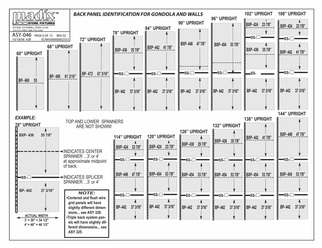
FIXTURE LOADING - PRODUCT SAFETY
WARNING! DO NOT EXCEED ANY OF THE MAXIMUM LOAD LIMITS IN THE FOLLOWING SECTIONS!
FRONT LOADED SHELVESIMPORTANT! Front loaded shelves create the most likely situation
for exceeding the fixture loading capacities. Compare the increases
in inch/lb. loadings of front loaded shelves over evenly loaded shelves,
PARTICULARLY ON WALL SECTIONS!
A front loaded shelf has a void between the back panel and the
merchandise. Take one half the loaded area dimension plus the
gap dimension at back and multiply times the weight on the shelf
in order to determine individual inch/lb. load.
FRONT LOADED SHELVES ON GONDOLAS
A1 7" + 4" = 11" x 300 lbs. or 3,300 inch/lbs.
A2 7" + 4" = 11" x 400 lbs. or 4,400 inch/lbs.
A3 9" + 4" = 13" x 500 lbs. or 6,500 inch/lbs.
SIDE A TOTAL = 14,200 inch/lbs.
B1 6" + 6" = 12" x 300 lbs. or 3,600 inch/ lbs.
B2 6" + 6" = 12" x 300 lbs. or 3,600 inch/ lbs.
B3 8" + 6" = 14" x 300 lbs. or 4,200 inch/lbs.
SIDE B TOTAL = 11,400 inch/lbs.
SUBTRACT B FROM A:
14,200 inch/lbs
-11,400 inch/lbs
2,800 inch/lbs
SAFE - 2,800 INCH/LBS
DOES NOT EXCEED
15,000 INCH/LBS
MAXIMUM
COLUMN LOADINGColumn loading is the vertical load, measured
in pounds, that can be applied on any upright.
Each upright bears ONE HALF OF THE LOAD
OF EACH SHELF THAT IT SUPPORTS.
MAXIMUM COLUMN LOAD IS 4,500 POUNDS,
DO NOT EXCEED!
750 lbs. plus 750 lbs. = 1500 lbs.
1500 lbs. divided by 2 =
750 lb. column load on the center upright
!
WALL SECTIONS - FRONT VIEW
WALL SECTIONS - TOP VIEW
500 lbs. plus 500 lbs. = 1000 lbs.
1000 lbs. divided by 2 =
500 lb. column load on the center upright

P.O. BOX 729 TERRELL, TEXAS 75160
214-515-5400 / 800-776-2349
ASY-046 PAGE 14 OF 15 REV. 02
10/18/06 AJB ECN#500000002553
FIXTURE LOADING - PRODUCT SAFETY
WARNING! DO NOT EXCEED ANY OF THE MAXIMUM LOAD LIMITS IN THE FOLLOWING SECTIONS!!
OFFSET LOADINGOffset loading is measured in inch/pounds and represents the bending load at the base shoe connection and the upright. To determine if you
exceed the load limit of the fixture, take the difference between the larger inch/lb. calculations on one side of the fixture and the inch /lb.
calculations on the other. THIS DIFFERENCE CANNOT EXCEED 15,000 INCH/LBS. In the case of wall sections, the calculation for the one side
CANNOT EXCEED 15,000 INCH/LBS.
EVENLY LOADED SHELVES ON GONDOLAS
Divide each shelf depth by 2...multiply times the weight on shelf to determine individual shelf load.
D1 18" / 2 = 9" x 300 lbs. or 2,700 inch/lbs.
D2 18" / 2 = 9" x 400 lbs. or 3,600 inch/lbs.
D3 22" / 2 = 11" x 500 lbs. or 5,500 inch/lbs.
SIDE D TOTAL = 11,800 inch/lbs.
E1 18" / 2 = 9" x 300 lbs. or 2,700 inch/lbs.
E2 18" / 2 = 9" x 300 lbs. or 2,700 inch/lbs.
E3 18" / 2 = 11" x 300 lbs. or 3,300 inch/lbs.
SIDE E TOTAL = 8,700 inch/lbs.
SUBTRACT E FROM D 11,800 inch/lbs.
- 8,700 inch/lbs.
3,100 inch/lbs.
SAFE! 3,100 INCH/LBS. DOES NOT
EXCEED 15,000 INCH/LBS. MAXIMUM
EVENLY LOADED SHELVES ON WALL SECTIONS Divide each shelf depth by 2...multiply times the weight
on shelf to determine individual shelf load.
F1 18" / 2 = 9" x 300 lbs. or 2,700 inch/lbs.
F2 18" / 2 = 9" x 400 lbs. or 3,600 inch/lbs.
F3 22" / 2 = 11" x 500 lbs. or 5,500 inch/lbs.
SIDE F TOTAL = 11,800 inch/lbs.
SAFE! 11,800 INCH/LBS. DOES NOT EXCEED
5,000 INCH/LBS. MAXIMUM

P.O. BOX 729 TERRELL, TEXAS 75160
214-515-5400 / 800-776-2349
ASY-046 PAGE 15 OF 15 REV. 02
10/18/06 AJB ECN#500000002553
POST THIS ENTIRE PAGE IN A CONSPICUOUS PLACE, CLEARLY VISIBLE TO ALL STORE PERSONEL
RE-LEVELING OF OFFSET LOADED FIXTURES
AFTER THE FIXTURE IS LOADED, IF A GAPPING OF THE SHELVES APPEARS ON THE HEAVILY LOADED SIDE, IT IS POSSIBLE THE ORIGINAL INSTALLATION IS THE CAUSE. CHECK THESE TWO CONDITIONS BEFORE PROCEEDING!CAUTION! BEFORE MAKING ANY ADJUSTMENTS TO ANY COMPONENTS BE SURE THAT ALL MERCHANDISE HAS BEEN REMOVED.
1. ALL UPRIGHTS MUST BE AT THE SAME HEIGHT!A. Visually sight across the top of the fixture to check for high or low uprights.B. If a row of shelves at a particular upright appeat to rise or sag at this indicates an unlevel sectionTO CORRECT: Pull a string across the top of the uprights from end to end.IF THE UPRIGHTS IS TOO LOW on lightly loaded section... a. Raise base shoe levelers on each side equally until upright touches stringline.IF UPRIGHTS TOO HIGH on lightly loaded section... a. Remove kickplates on both sides of the low upright. b. Screw upright leveler out, or down, raising the top upright until it touches stringline. c. Screw base shoe levelers down an equal number of turns until base shoes lock up against the upright.IF UPRIGHTS TOO HIGH on lightly or heavily loaded section... a. Remove kickplates on both sides of the high upright. b. Screw upright leveler up into upright, this may solve the "too high" problem, if not.... c. Screw loose shoe levelers up into shoe an equal number of turns until top of upright touches stringline.
2. NONE OF THE SECTIONS IN THE RUN HAVE BEEN MOVED OUT OF ALIGNMENTA. Visually sight along the front of the base shelves.B. Compare the front of the base shelves to a tile line.TO CORRECT: Facing the wedge shaped gap areas, physically push the section back into line, closing the gaps. Depending on the merchandise, it may benecessary to unload or partially unload the section before moving. Attempt to move the section by applying foot pressure at the kickplate joint only...if not possible, a. Place a 2 x 4 block against the kickplate joint and tap back into alignment...or... b. Use a jack and 2 x 4 block against kickplate joint... jack should be braced across the aisle against a long 2 x 4 spanning several kickplate joints.IF THE ABOVE CONDITIONS ARE NOW CORRECT, look for shelf gaps on the heavily loaded side...the base shelf joint will be tight, but the upper shelveswill have increasingly larger wedge shape gaps at the top, REMOVE KICKPLATES ON BOTH SIDES FOR AT LEAST ONE SECTION ON EITHER SIDE OF THE HEAVILYLOADED SECTION. ON THE LIGHTLY LOADED SIDE, a. Run upright levelers down to the floor. b. Run base shoe leveler up into shoe until the pressure is off of it...1/4" free movement. THEN...ON THE HEAVILY LOADED SIDE, c. Begin at the first heavily loaded upright TO YOUR RIGHT, facing the heavily loaded side...run the base shoe leveler down until all the shelf gaps at that upright close tightly. d. Repeat c. with remaining heavily loaded uprights, WORKING TO YOUR LEFT. THEN...ON THE LIGHTLY LOADED SIDE, e. Run loose levelers down until shoe locks up against the upright. f. Replace kickplates on both sides.
CAUTION!CARE SHOULD BE TAKEN TO AVOID
ACCIDENTS / INJURY WHILE
ADJUSTING MERCHANDISED
FIXTURES!
DO NOT ATTEMPT TO
ADJUST FIXTURES THAT ARE
ALREADY ANCHORED
CAUTION!DO NOT MOVE LOADED FIXTURES
ALWAYS REMOVE MERCHANDISE
TO MOVE ANY FIXTURE.