Embed Size (px)
Citation preview
MAXI-KOOLCE I L ING , AT T I C OR ROOF MOUNTEDSE L F CONTA INED OR SP L I T SYST EMS
Specialized Environmental Air Conditioning Systems for Computer Rooms, Telecommunications Facilities,Laboratories, and Hospitals
2 THRU 12 TON
ISO9 0 0 0
REGISTEREDC O M P A N Y
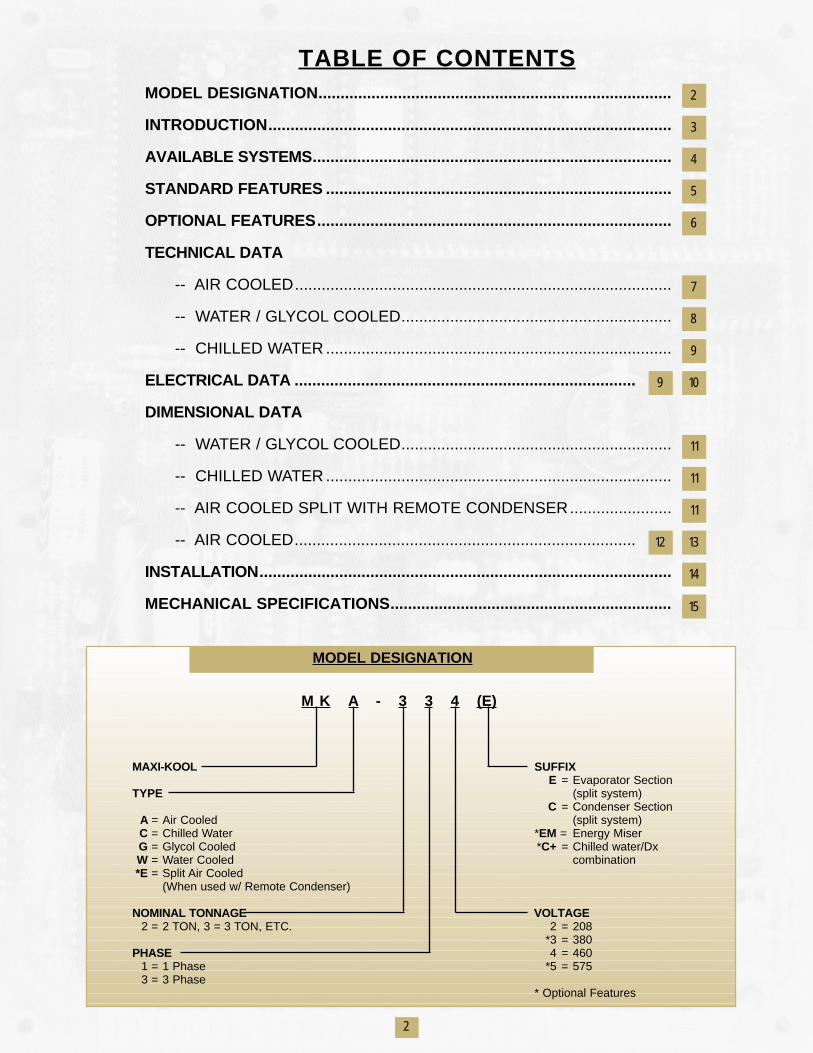
TABLE OF CONTENTSMODEL DESIGNATION................................................................................
INTRODUCTION...........................................................................................
AVAILABLE SYSTEMS.................................................................................
STANDARD FEATURES ..............................................................................
OPTIONAL FEATURES................................................................................
TECHNICAL DATA
-- AIR COOLED.....................................................................................
-- WATER / GLYCOL COOLED.............................................................
-- CHILLED WATER ..............................................................................
ELECTRICAL DATA .............................................................................
DIMENSIONAL DATA
-- WATER / GLYCOL COOLED.............................................................
-- CHILLED WATER ..............................................................................
-- AIR COOLED SPLIT WITH REMOTE CONDENSER.......................
-- AIR COOLED.............................................................................
INSTALLATION.............................................................................................
MECHANICAL SPECIFICATIONS................................................................
2
3
4
5
6
7
8
9
109
11
12
11
11
13
14
15
MODEL DESIGNATION
M K A - 3 3 4 (E)
MAXI-KOOL SUFFIXE = Evaporator Section
TYPE (split system)C = Condenser Section
A = Air Cooled (split system)C = Chilled Water *EM = Energy MiserG = Glycol Cooled *C+ = Chilled water/DxW = Water Cooled combination*E = Split Air Cooled
(When used w/ Remote Condenser)
NOMINAL TONNAGE VOLTAGE2 = 2 TON, 3 = 3 TON, ETC. 2 = 208
*3 = 380PHASE 4 = 460
1 = 1 Phase *5 = 5753 = 3 Phase
* Optional Features
2
Compu-Aire understands the special environmental control (Temperature, Humidity, Air Filtration) needs for both
main frame and main-computer rooms, and presents to the user the MAXI-KOOL unit.
ETL Listed, the MAXI-KOOL is installed in the ceiling or roof and is available in over 50 capacities and coolingmethods.
The MAXI-KOOL offers space saving compact design with many flexible configuration options, whichallows the system to be tailored to the needs of your application. One more reason why users prefer the
MAXI-KOOL is for its draw through design for the maximum heat transfer efficiency.
Compu-Aire’s unique ceiling and roof mounted air conditioner not only keeps pace with rapidly changingcomputer technology, but also offers the highest degree of reliability in component and system operation.
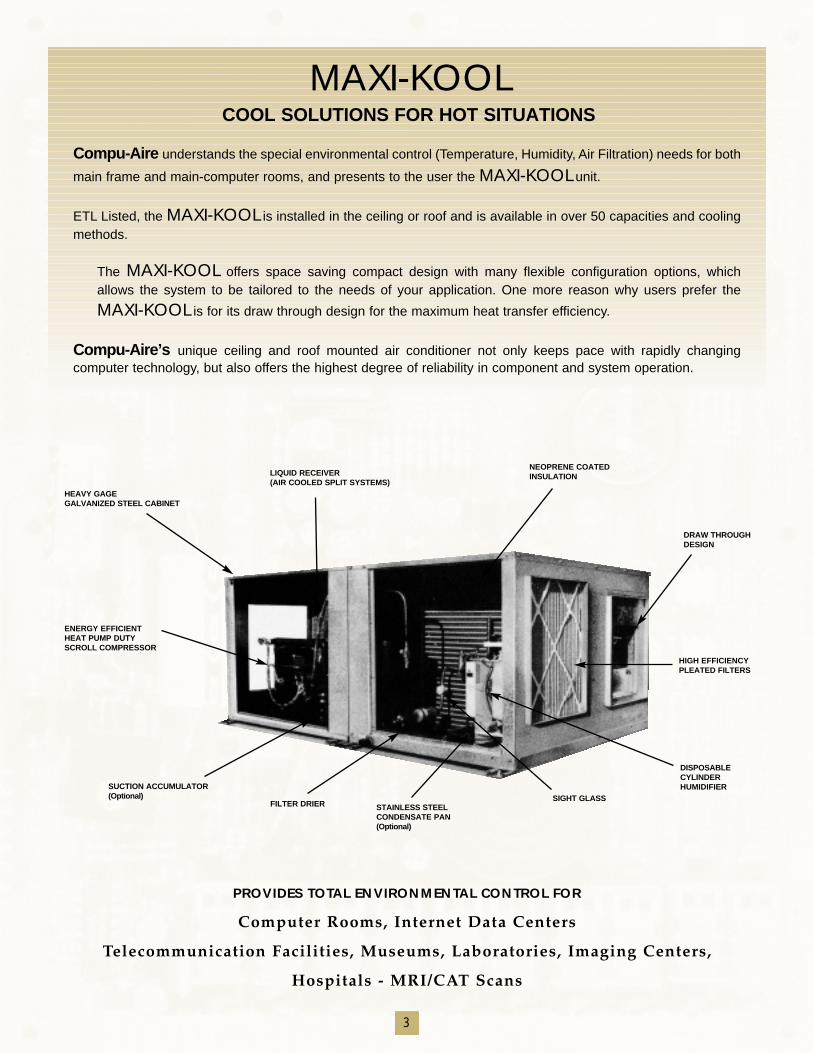
HEAVY GAGEGALVANIZED STEEL CABINET
LIQUID RECEIVER (AIR COOLED SPLIT SYSTEMS)
NEOPRENE COATEDINSULATION
DRAW THROUGHDESIGN
HIGH EFFICIENCY PLEATED FILTERS
DISPOSABLE CYLINDERHUMIDIFIER
ENERGY EFFICIENTHEAT PUMP DUTYSCROLL COMPRESSOR
SUCTION ACCUMULATOR(Optional)
FILTER DRIER STAINLESS STEELCONDENSATE PAN(Optional)
SIGHT GLASS
MAXI-KOOLCOOL SOLUTIONS FOR HOT SITUATIONS
PROVIDES TOTAL ENVIRONMENTAL CONTROL FOR
Computer Rooms, Internet Data Centers
Telecommunication Facilities, Museums, Laboratories, Imaging Centers,
Hospitals - MRI/CAT Scans
3
4
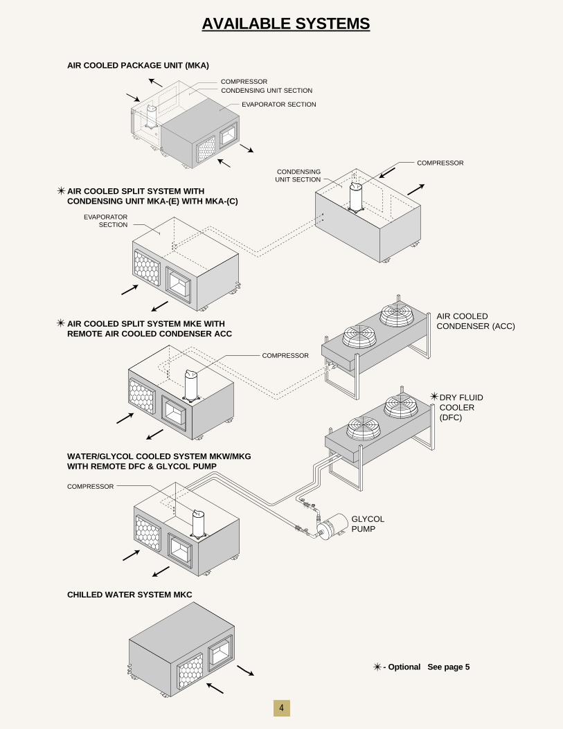
AVAILABLE SYSTEMS
CONDENSING UNIT SECTION
EVAPORATOR SECTION
EVAPORATOR SECTION
CONDENSINGUNIT SECTION
AIR COOLED PACKAGE UNIT (MKA)
AIR COOLED SPLIT SYSTEM WITHCONDENSING UNIT MKA-(E) WITH MKA-(C)
AIR COOLED SPLIT SYSTEM MKE WITHREMOTE AIR COOLED CONDENSER ACC
AIR COOLEDCONDENSER (ACC)
COMPRESSOR
COMPRESSOR
COMPRESSOR
COMPRESSOR
DRY FLUIDCOOLER(DFC)
GLYCOLPUMP
WATER/GLYCOL COOLED SYSTEM MKW/MKGWITH REMOTE DFC & GLYCOL PUMP
CHILLED WATER SYSTEM MKC
✴
✴
✴
✴ - Optional See page 5
5
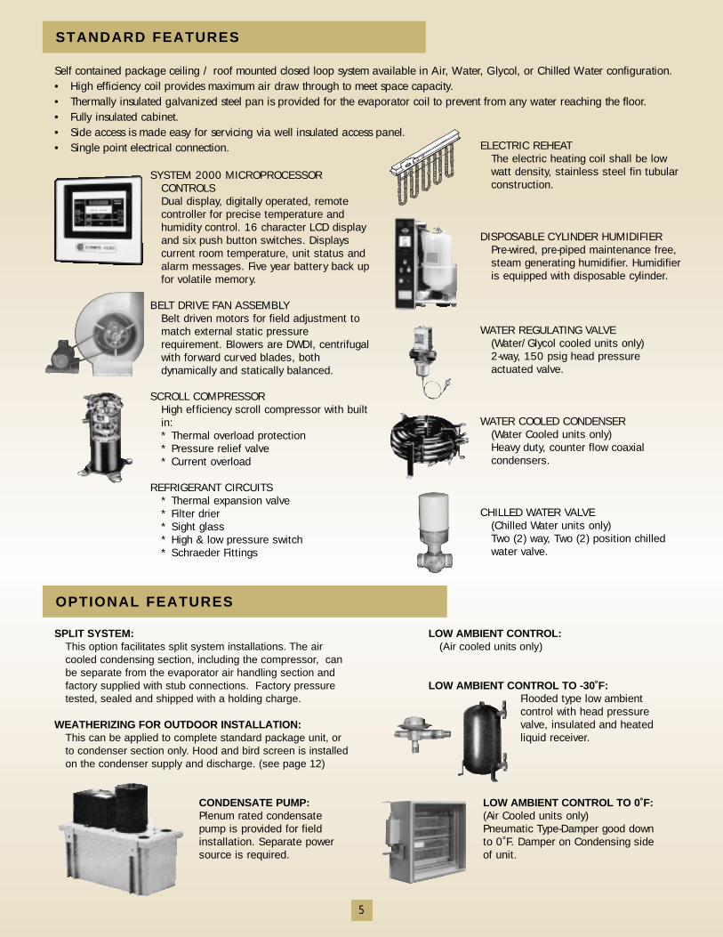
SYSTEM 2000 MICROPROCESSORCONTROLS Dual display, digitally operated, remotecontroller for precise temperature andhumidity control. 16 character LCD displayand six push button switches. Displayscurrent room temperature, unit status andalarm messages. Five year battery back upfor volatile memory.
BELT DRIVE FAN ASSEMBLYBelt driven motors for field adjustment tomatch external static pressurerequirement. Blowers are DWDI, centrifugalwith forward curved blades, bothdynamically and statically balanced.
SCROLL COMPRESSORHigh efficiency scroll compressor with builtin:* Thermal overload protection* Pressure relief valve* Current overload
REFRIGERANT CIRCUITS* Thermal expansion valve* Filter drier* Sight glass* High & low pressure switch* Schraeder Fittings
ELECTRIC REHEATThe electric heating coil shall be lowwatt density, stainless steel fin tubularconstruction.
DISPOSABLE CYLINDER HUMIDIFIERPre-wired, pre-piped maintenance free,steam generating humidifier. Humidifieris equipped with disposable cylinder.
WATER REGULATING VALVE(Water/Glycol cooled units only)2-way, 150 psig head pressureactuated valve.
WATER COOLED CONDENSER(Water Cooled units only)Heavy duty, counter flow coaxialcondensers.
CHILLED WATER VALVE(Chilled Water units only)Two (2) way, Two (2) position chilledwater valve.
STANDARD FEATURES
Self contained package ceiling / roof mounted closed loop system available in Air, Water, Glycol, or Chilled Water configuration.• High efficiency coil provides maximum air draw through to meet space capacity.• Thermally insulated galvanized steel pan is provided for the evaporator coil to prevent from any water reaching the floor.• Fully insulated cabinet.• Side access is made easy for servicing via well insulated access panel.• Single point electrical connection.
SPLIT SYSTEM:This option facilitates split system installations. The aircooled condensing section, including the compressor, canbe separate from the evaporator air handling section andfactory supplied with stub connections. Factory pressuretested, sealed and shipped with a holding charge.
WEATHERIZING FOR OUTDOOR INSTALLATION:This can be applied to complete standard package unit, orto condenser section only. Hood and bird screen is installedon the condenser supply and discharge. (see page 12)
CONDENSATE PUMP:Plenum rated condensatepump is provided for fieldinstallation. Separate powersource is required.
LOW AMBIENT CONTROL:(Air cooled units only)
LOW AMBIENT CONTROL TO -30˚F:Flooded type low ambientcontrol with head pressurevalve, insulated and heatedliquid receiver.
LOW AMBIENT CONTROL TO 0˚F:(Air Cooled units only)Pneumatic Type-Damper good downto 0˚F. Damper on Condensing sideof unit.
OPTIONAL FEATURES
6
Compu-Aire Energy Miser System isintegrated with glycol cooled Maxi-Kool. At entering glycol temperature of45˚F and below, the Energy MiserSystem can provide total systemcapacity, thereby resulting insubstantial reduction in operatingcosts.
SINGLE PHASE:System can be provided for singlephase power supply, 208 or 230voltage where available and for unitsup to and including 5 tons.
HOT GAS BYPASS:Hot gas bypass valve is factoryinstalled in the compressor dischargefor precise capacity control in thecooling mode and for protectionagainst coil freeze up during partial orlow load conditions. For Air CooledSplit Systems, a hot gas bypass lineneeds to be field installed between theevaporator and condenser section.
SPECIAL WATER VALVE FORMKW / MKG SYSTEMS:
The following alternate water valvesare availableA. Three-way head pressure
regulating valve rated at 150 psig.B. Two-way head pressure regulating
valve rated at 300 psig. C. Three-way head pressure
regulating valve rated at 300 psig.
ALTERNATE REHEAT:• Steam Reheat: Coil is factory piped
with a 2-way on/off control valve.• Hot Water Reheat: Coil is factory
piped with a 2-way on/off control valve
• Hot Gas Reheat: Coil is factory piped with a 3-way solenoid valve and refrigerant check valve.
ALTERNATE HUMIDIFIER:Steam Humidifier: Dry steam, doublejacketed type, piped with a solenoidvalve. Steam trap and Y-strainer to befactory provided and field installedoutside of the unit.
DISCONNECT SWITCH:Fused Disconnect: A fused
disconnect switch can be supplied
with the indoor unit for field installation. Fuses to be fieldsupplied and installed.
Rain Tight Disconnect: A rain-tight, fused disconnect switch can be supplied with the outdoor unit for field installation. Fuses to be fieldsupplied and installed.
HACR Circuit Breaker: HACR approved circuit breaker can be supplied (factory installed) with the unit.
REMOTE AIR COOLED CONDENSER:Remote air cooled condenser is a lowprofile design constructed of copper tubeand high efficiency aluminum fin coil. Afactory wired control panel is provided forfield installation in a weather proofhousing on the condenser.
DRY FLUID COOLER & PUMP PACKAGE:A DFC matching the water cooledcondenser capacity, at design elevation,glycol solution percentage and ambienttemperature, can be provided for remoteinstallation and field piped for thewater/glycol solution, and interconnectedto the indoor air conditioner.
A close coupled centrifugal pump andmotor for circulating glycol solution canbe provided for field mounting, with apump motor weathershield.
FOUR YEAR COMPRESSORWARRANTY:Compressor is warranted for additional4 years. This additional warranty takeseffect after expiration of the 1st yearstandard warranty. Total coverage isextended to 5 years from the date ofstart up.
SPECIAL INDUSTRIAL APPLICATIONS:The Maxi-Kool can be provided with avariety of special application optionssuch as:
• Stainless Steel cabinet for corrosionresistance
• Double wall construction for noisereduction
• Epoxy / Phenolic coated / Copper - Copper coils for corrosion resistance
• Internally isolated blowers forvibration reduction
• TEFC motors• High Efficiency Motors
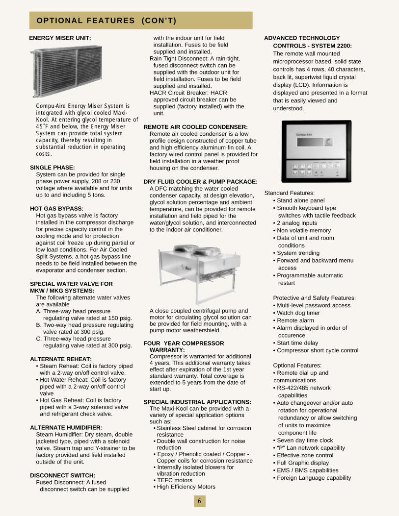
OPTIONAL FEATURES (CON’T)
Standard Features:• Stand alone panel• Smooth keyboard type
switches with tactile feedback• 2 analog inputs• Non volatile memory• Data of unit and room
conditions• System trending• Forward and backward menu
access• Programmable automatic
restart
Protective and Safety Features:• Multi-level password access• Watch dog timer• Remote alarm• Alarm displayed in order of
occurence• Start time delay• Compressor short cycle control
Optional Features:• Remote dial up and communications• RS-422/485 network
capabilities• Auto changeover and/or auto
rotation for operational redundancy or allow switching of units to maximize component life
• Seven day time clock• “P” Lan network capability• Effective zone control• Full Graphic display• EMS / BMS capabilities• Foreign Language capability
ENERGY MISER UNIT: ADVANCED TECHNOLOGYCONTROLS - SYSTEM 2200:The remote wall mountedmicroprocessor based, solid statecontrols has 4 rows, 40 characters,back lit, supertwist liquid crystaldisplay (LCD). Information isdisplayed and presented in a formatthat is easily viewed andunderstood.
7
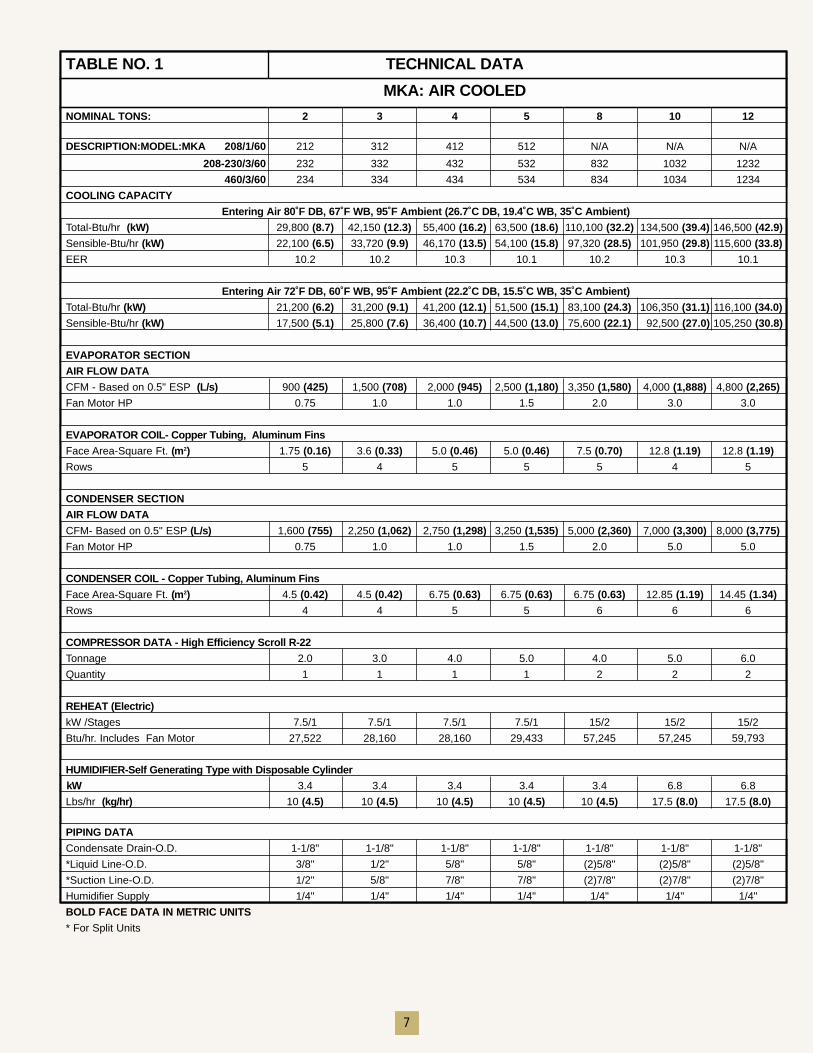
TABLE NO. 1 TECHNICAL DATA
MKA: AIR COOLED
NOMINAL TONS: 2 3 4 5 8 10 12
DESCRIPTION:MODEL:MKA 208/1/60 212 312 412 512 N/A N/A N/A
208-230/3/60 232 332 432 532 832 1032 1232
460/3/60 234 334 434 534 834 1034 1234
COOLING CAPACITY
Entering Air 80˚F DB, 67˚F WB, 95˚F Ambient (26.7˚C DB, 19.4˚C WB, 35˚C Ambient)
Total-Btu/hr (kW) 29,800 (8.7) 42,150 (12.3) 55,400 (16.2) 63,500 (18.6) 110,100 (32.2) 134,500 (39.4) 146,500 (42.9)
Sensible-Btu/hr (kW) 22,100 (6.5) 33,720 (9.9) 46,170 (13.5) 54,100 (15.8) 97,320 (28.5) 101,950 (29.8) 115,600 (33.8)
EER 10.2 10.2 10.3 10.1 10.2 10.3 10.1
Entering Air 72˚F DB, 60˚F WB, 95˚F Ambient (22.2˚C DB, 15.5˚C WB, 35˚C Ambient)
Total-Btu/hr (kW) 21,200 (6.2) 31,200 (9.1) 41,200 (12.1) 51,500 (15.1) 83,100 (24.3) 106,350 (31.1) 116,100 (34.0)
Sensible-Btu/hr (kW) 17,500 (5.1) 25,800 (7.6) 36,400 (10.7) 44,500 (13.0) 75,600 (22.1) 92,500 (27.0) 105,250 (30.8)
EVAPORATOR SECTION
AIR FLOW DATA
CFM - Based on 0.5" ESP (L/s) 900 (425) 1,500 (708) 2,000 (945) 2,500 (1,180) 3,350 (1,580) 4,000 (1,888) 4,800 (2,265)
Fan Motor HP 0.75 1.0 1.0 1.5 2.0 3.0 3.0
EVAPORATOR COIL- Copper Tubing, Aluminum Fins
Face Area-Square Ft. (m2) 1.75 (0.16) 3.6 (0.33) 5.0 (0.46) 5.0 (0.46) 7.5 (0.70) 12.8 (1.19) 12.8 (1.19)
Rows 5 4 5 5 5 4 5
CONDENSER SECTION
AIR FLOW DATA
CFM- Based on 0.5" ESP (L/s) 1,600 (755) 2,250 (1,062) 2,750 (1,298) 3,250 (1,535) 5,000 (2,360) 7,000 (3,300) 8,000 (3,775)
Fan Motor HP 0.75 1.0 1.0 1.5 2.0 5.0 5.0
CONDENSER COIL - Copper Tubing, Aluminum Fins
Face Area-Square Ft. (m2) 4.5 (0.42) 4.5 (0.42) 6.75 (0.63) 6.75 (0.63) 6.75 (0.63) 12.85 (1.19) 14.45 (1.34)
Rows 4 4 5 5 6 6 6
COMPRESSOR DATA - High Efficiency Scroll R-22
Tonnage 2.0 3.0 4.0 5.0 4.0 5.0 6.0
Quantity 1 1 1 1 2 2 2
REHEAT (Electric)
kW /Stages 7.5/1 7.5/1 7.5/1 7.5/1 15/2 15/2 15/2
Btu/hr. Includes Fan Motor 27,522 28,160 28,160 29,433 57,245 57,245 59,793
HUMIDIFIER-Self Generating Type with Disposable Cylinder
kW 3.4 3.4 3.4 3.4 3.4 6.8 6.8
Lbs/hr (kg/hr) 10 (4.5) 10 (4.5) 10 (4.5) 10 (4.5) 10 (4.5) 17.5 (8.0) 17.5 (8.0)
PIPING DATA
Condensate Drain-O.D. 1-1/8" 1-1/8" 1-1/8" 1-1/8" 1-1/8" 1-1/8" 1-1/8"
*Liquid Line-O.D. 3/8" 1/2" 5/8" 5/8" (2)5/8" (2)5/8" (2)5/8"
*Suction Line-O.D. 1/2" 5/8" 7/8" 7/8" (2)7/8" (2)7/8" (2)7/8"
Humidifier Supply 1/4" 1/4" 1/4" 1/4" 1/4" 1/4" 1/4"
BOLD FACE DATA IN METRIC UNITS
* For Split Units
8
11.412.411.111.212.810.9
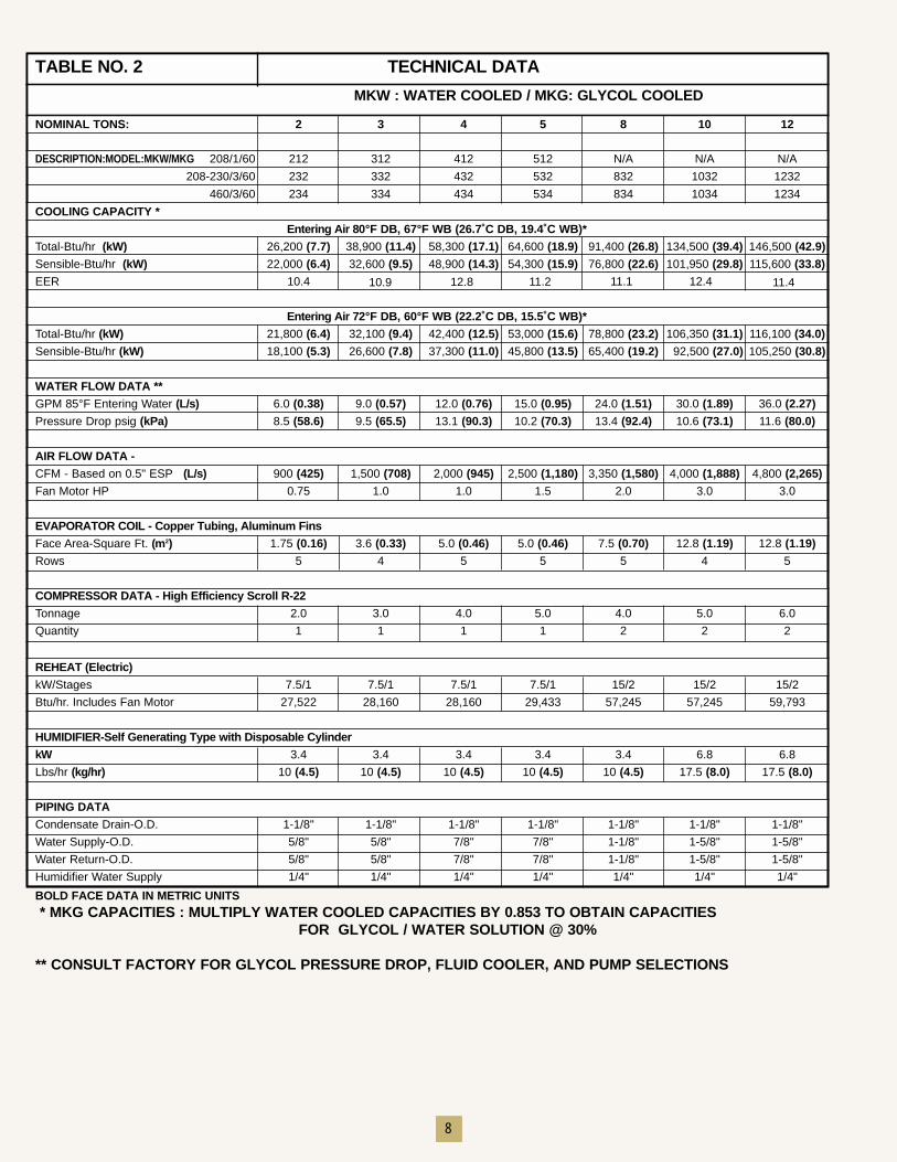
TABLE NO. 2 TECHNICAL DATA
MKW : WATER COOLED / MKG: GLYCOL COOLED
NOMINAL TONS: 2 3 4 5 8 10 12
DESCRIPTION:MODEL:MKW/MKG 208/1/60 212 312 412 512 N/A N/A N/A
208-230/3/60 232 332 432 532 832 1032 1232
460/3/60 234 334 434 534 834 1034 1234
COOLING CAPACITY *
Entering Air 80°F DB, 67°F WB (26.7˚C DB, 19.4˚C WB)*
Total-Btu/hr (kW) 26,200 (7.7) 38,900 (11.4) 58,300 (17.1) 64,600 (18.9) 91,400 (26.8) 134,500 (39.4) 146,500 (42.9)
Sensible-Btu/hr (kW) 22,000 (6.4) 32,600 (9.5) 48,900 (14.3) 54,300 (15.9) 76,800 (22.6) 101,950 (29.8) 115,600 (33.8)
EER 10.4
Entering Air 72°F DB, 60°F WB (22.2˚C DB, 15.5˚C WB)*
Total-Btu/hr (kW) 21,800 (6.4) 32,100 (9.4) 42,400 (12.5) 53,000 (15.6) 78,800 (23.2) 106,350 (31.1) 116,100 (34.0)
Sensible-Btu/hr (kW) 18,100 (5.3) 26,600 (7.8) 37,300 (11.0) 45,800 (13.5) 65,400 (19.2) 92,500 (27.0) 105,250 (30.8)
WATER FLOW DATA **
GPM 85°F Entering Water (L/s) 6.0 (0.38) 9.0 (0.57) 12.0 (0.76) 15.0 (0.95) 24.0 (1.51) 30.0 (1.89) 36.0 (2.27)Pressure Drop psig (kPa) 8.5 (58.6) 9.5 (65.5) 13.1 (90.3) 10.2 (70.3) 13.4 (92.4) 10.6 (73.1) 11.6 (80.0)
AIR FLOW DATA - CFM - Based on 0.5" ESP (L/s) 900 (425) 1,500 (708) 2,000 (945) 2,500 (1,180) 3,350 (1,580) 4,000 (1,888) 4,800 (2,265)Fan Motor HP 0.75 1.0 1.0 1.5 2.0 3.0 3.0
EVAPORATOR COIL - Copper Tubing, Aluminum Fins Face Area-Square Ft. (m2) 1.75 (0.16) 3.6 (0.33) 5.0 (0.46) 5.0 (0.46) 7.5 (0.70) 12.8 (1.19) 12.8 (1.19)Rows 5 4 5 5 5 4 5
COMPRESSOR DATA - High Efficiency Scroll R-22Tonnage 2.0 3.0 4.0 5.0 4.0 5.0 6.0
Quantity 1 1 1 1 2 2 2
REHEAT (Electric)kW/Stages 7.5/1 7.5/1 7.5/1 7.5/1 15/2 15/2 15/2
Btu/hr. Includes Fan Motor 27,522 28,160 28,160 29,433 57,245 57,245 59,793
HUMIDIFIER-Self Generating Type with Disposable CylinderkW 3.4 3.4 3.4 3.4 3.4 6.8 6.8
Lbs/hr (kg/hr) 10 (4.5) 10 (4.5) 10 (4.5) 10 (4.5) 10 (4.5) 17.5 (8.0) 17.5 (8.0)
PIPING DATACondensate Drain-O.D. 1-1/8" 1-1/8" 1-1/8" 1-1/8" 1-1/8" 1-1/8" 1-1/8"
Water Supply-O.D. 5/8" 5/8" 7/8" 7/8" 1-1/8" 1-5/8" 1-5/8"
Water Return-O.D. 5/8" 5/8" 7/8" 7/8" 1-1/8" 1-5/8" 1-5/8"
Humidifier Water Supply 1/4" 1/4" 1/4" 1/4" 1/4" 1/4" 1/4"
BOLD FACE DATA IN METRIC UNITS
* MKG CAPACITIES : MULTIPLY WATER COOLED CAPACITIES BY 0.853 TO OBTAIN CAPACITIES FOR GLYCOL / WATER SOLUTION @ 30%
** CONSULT FACTORY FOR GLYCOL PRESSURE DROP, FLUID COOLER, AND PUMP SELECTIONS
9
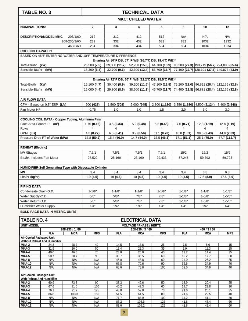
TABLE NO. 3 TECHNICAL DATAMKC: CHILLED WATER
NOMINAL TONS: 2 3 4 5 8 10 12
DESCRIPTION:MODEL:MKC 208/1/60 212 312 412 512 N/A N/A N/A208-230/3/60 232 332 432 532 832 1032 1232
460/3/60 234 334 434 534 834 1034 1234
COOLING CAPACITY BASED ON 45°F ENTERING WATER AND 10°F TEMPERATURE DIFFERENCE
Entering Air 80°F DB, 67° F WB (26.7˚C DB, 19.4˚C WB)*Total-Btu/hr (kW) 25,500 (7.5) 39,800 (11.7) 52,200 (15.3) 64,700 (18.9) 93,200 (27.3) 193,719 (56.7) 224,000 (65.6)Sensible-Btu/hr (kW) 18,300 (5.4) 32,700 (9.6) 42,300 (12.4) 53,700 (15.7) 77,400 (22.7) 128,191 (37.5) 149,876 (43.9)
Entering Air 72°F DB, 60°F WB (22.2˚C DB, 15.5˚C WB)*
Total-Btu/hr (kW) 16,100 (4.7) 30,400 (8.9) 39,200 (11.5) 47,100 (13.8) 75,200 (22.0) 96,831 (28.4) 112,166 (32.8)
Sensible-Btu/hr (kW) 15,000 (4.4) 29,300 (8.6) 38,600 (11.3) 46,700 (13.7) 74,400 (21.8) 96,831 (28.4) 112,166 (32.8)
AIR FLOW DATA
CFM - Based on 0.5" ESP (L/s) 900 (425) 1,500 (708) 2,000 (945) 2,500 (1,180) 3,350 (1,580) 4,500 (2,124) 5,400 (2,548)
Fan Motor HP 0.75 1.0 1.0 1.5 2.0 3.0 3.0
COOLING COIL DATA - Copper Tubing, Aluminum Fins Face Area-Square Ft. (m2) 1.75 (0.16) 3.6 (0.33) 5.2 (0.48) 5.2 (0.48) 7.6 (0.71) 12.8 (1.19) 12.8 (1.19)Rows 4 4 4 4 4 4 4GPM (L/s) 4.3 (0.27) 6.5 (0.41) 8.9 (0.56) 11.1 (0.70) 16.0 (1.01) 38.5 (2.43) 44.8 (2.83)Pressure Drop FT of Water (kPa) 16.8 (50.2) 15.4 (46.0) 14.7 (44.0) 15.5 (46.3) 17.1 (51.1) 25.1 (75.0) 37.7 (112.7)
REHEAT (Electric)
kW /Stages 7.5/1 7.5/1 7.5/1 7.5/1 15/2 15/2 15/2
Btu/hr. Includes Fan Motor 27,522 28,160 28,160 29,433 57,245 59,793 59,793
HUMIDIFIER-Self Generating Type with Disposable CylinderkW 3.4 3.4 3.4 3.4 3.4 6.8 6.8Lbs/hr (kg/hr) 10 (4.5) 10 (4.5) 10 (4.5) 10 (4.5) 10 (4.5) 17.5 (8.0) 17.5 (8.0)
PIPING DATA
Condensate Drain-O.D. 1-1/8" 1-1/8" 1-1/8" 1-1/8" 1-1/8" 1-1/8" 1-1/8"
Water Supply-O.D. 5/8" 5/8" 7/8" 7/8" 1-1/8" 1-5/8" 1-5/8"
Water Return-O.D. 5/8" 5/8" 7/8" 7/8" 1-1/8" 1-5/8" 1-5/8"
Humidifier Water Supply 1/4" 1/4" 1/4" 1/4" 1/4" 1/4" 1/4"
BOLD FACE DATA IN METRIC UNITS
TABLE NO. 4 ELECTRICAL DATAUNIT MODEL VOLTAGE / PHASE / HERTZ
208-230 / 1 /60 208-230 / 3 / 60 460 / 3 / 60FLA MCA MFS FLA MCA MFS FLA MCA MFS
Air Cooled Packaged UnitWithout Reheat And HumidifierMKA-2 24.8 28.2 40 14.5 16.6 25 7.5 8.6 15MKA-3 31.5 36.0 50 19.4 22.3 35 9.9 11.3 15MKA-4 40.0 46.6 70 23.0 26.8 40 12.2 14.4 25MKA-5 50.7 58.7 90 30.7 35.5 60 15.2 17.7 30MKA-8 N/A N/A N/A 45.0 48.8 60 24.0 26.2 35MKA-10 N/A N/A N/A 65.8 70.6 90 32.6 34.9 40MKA-12 N/A N/A N/A 68.6 73.8 100 32.6 34.9 40
Air Cooled Packaged UnitWith Reheat And HumidifierMKA-2 60.9 73.3 90 35.3 42.6 50 16.9 20.4 25MKA-3 67.6 81.0 100 40.2 48.3 60 19.7 23.8 30MKA-4 76.1 91.7 125 43.8 52.8 70 21.6 26.1 35MKA-5 86.8 103.8 150 51.5 61.5 80 24.6 29.5 40MKA-8 N/A N/A N/A 71.7 85.9 100 34.2 41.1 50MKA-10 N/A N/A N/A 88.2 103.5 125 41.8 48.4 60MKA-12 N/A N/A N/A 89.6 105.2 125 41.8 48.4 60
10
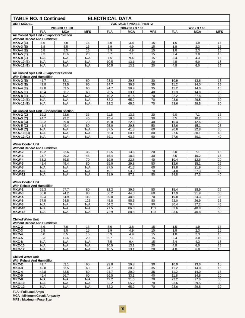
TABLE NO. 4 Continued ELECTRICAL DATAUNIT MODEL VOLTAGE / PHASE / HERTZ
208-230 / 1 /60 208-230 / 3 / 60 460 / 3 / 60FLA MCA MFS FLA MCA MFS FLA MCA MFS
Air Cooled Split Unit - Evaporator SectionWithout Reheat And HumidifierMKA-2 (E) 5.6 7.0 15 3.0 3.8 15 1.5 1.9 15MKA-3 (E) 6.8 8.5 15 3.9 4.9 15 1.8 2.3 15MKA-4 (E) 6.8 8.5 15 3.9 4.9 15 1.8 2.3 15MKA-5 (E) 9.3 11.6 20 5.7 7.1 15 2.4 3.0 15MKA-8 (E) N/A N/A N/A 7.5 9.4 15 3.4 4.3 15MKA-10 (E) N/A N/A N/A 10.5 13.1 20 4.8 6.0 15MKA-12 (E) N/A N/A N/A 10.5 13.1 20 4.8 6.0 15
Air Cooled Split Unit - Evaporator SectionWith Reheat And HumidifierMKA-2 (E) 41.7 52.1 60 23.8 29.8 30 10.9 13.6 15MKA-3 (E) 42.8 53.5 60 24.7 30.9 35 11.2 14.0 15MKA-4 (E) 42.8 53.5 60 24.7 30.9 35 11.2 14.0 15MKA-5 (E) 45.4 56.7 60 26.5 33.1 40 11.8 14.8 20MKA-8 (E) N/A N/A N/A 49.2 61.5 70 22.2 27.8 30MKA-10 (E) N/A N/A N/A 52.2 65.2 70 23.6 29.5 30MKA-12 (E) N/A N/A N/A 52.2 65.2 70 23.6 29.5 30
Air Cooled Split Unit - Condensing SectionMKA-2 (C) 19.2 22.6 35 11.5 13.6 20 6.0 7.1 15MKA-3 (C) 24.7 29.2 45 15.4 18.3 30 8.5 10.2 15MKA-4 (C) 33.2 39.8 70 19.0 22.8 40 10.4 12.6 20MKA-5 (C) 41.4 49.4 80 25.0 29.8 50 12.6 15.1 25MKA-8 (C) N/A N/A N/A 37.5 41.3 60 20.6 22.8 30MKA-10 (C) N/A N/A N/A 55.3 60.1 80 27.6 30.1 40MKA-12 (C) N/A N/A N/A 59.1 63.3 90 27.6 30.1 40
Water Cooled UnitWithout Reheat And HumidifierMKW-2 19.2 22.6 35 11.5 13.6 20 3.0 7.1 15MKW-3 24.7 29.2 45 15.4 18.3 30 8.5 10.2 15MKW-4 33.2 39.8 70 19.0 22.8 40 10.4 12.6 20MKW-5 41.4 49.4 80 25.0 29.8 50 12.6 15.1 25MKW-8 N/A N/A N/A 37.5 41.3 60 19.8 21.9 30MKW-10 N/A N/A N/A 49.1 53.9 70 24.8 27.3 40MKW-12 N/A N/A N/A 51.9 57.1 80 24.8 27.3 40
Water Cooled UnitWith Reheat And HumidifierMKW-2 55.3 67.7 80 32.3 39.6 50 15.4 18.9 25MKW-3 60.8 74.2 90 36.2 44.3 60 17.9 21.9 30MKW-4 69.3 84.9 110 39.8 48.8 70 19.8 24.3 35MKW-5 77.5 94.5 125 45.8 55.5 80 22.0 26.9 35MKW-8 N/A N/A N/A 64.2 78.4 90 30.4 37.2 45MKW-10 N/A N/A N/A 71.5 86.8 110 33.6 40.8 50MKW-12 N/A N/A N/A 72.9 88.5 110 33.6 40.8 50
Chilled Water UnitWithout Reheat And HumidifierMKC-2 5.6 7.0 15 3.0 3.8 15 1.5 1.9 15MKC-3 6.8 8.5 15 3.9 4.9 15 1.8 2.3 15MKC-4 6.8 8.5 15 3.9 4.9 15 1.8 2.3 15MKC-5 9.3 11.6 20 5.7 7.1 15 2.4 3.0 15MKC-8 N/A N/A N/A 7.5 9.4 15 3.4 4.3 15MKC-10 N/A N/A N/A 10.5 13.1 20 4.8 6.0 15MKC-12 N/A N/A N/A 10.5 13.1 20 4.8 6.0 15
Chilled Water UnitWith Reheat And HumidifierMKC-2 41.7 52.1 60 23.8 29.8 30 10.9 13.6 15MKC-3 42.8 53.5 60 24.7 30.9 35 11.2 14.0 15MKC-4 42.8 53.5 60 24.7 30.9 35 11.2 14.0 15MKC-5 45.4 56.7 60 26.5 33.1 40 11.8 14.8 20MKC-8 N/A N/A N/A 49.2 31.5 70 22.2 27.8 30MKC-10 N/A N/A N/A 52.2 65.2 70 23.6 29.5 30MKC-12 N/A N/A N/A 52.2 65.2 70 23.6 29.5 30
FLA : Full Load AmpsMCA : Minimum Circuit AmpacityMFS : Maximum Fuse Size
11
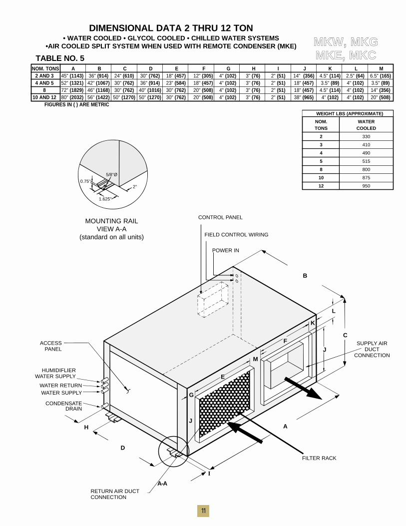
NOM. TONS A B C D E F G H I J K L M2 AND 3 45" (1143) 36" (914) 24" (610) 30" (762) 18" (457) 12" (305) 4" (102) 3" (76) 2" (51) 14" (356) 4.5" (114) 2.5" (64) 6.5" (165)4 AND 5 52" (1321) 42" (1067) 30" (762) 36" (914) 23" (584) 18" (457) 4" (102) 3" (76) 2" (51) 18" (457) 3.5" (89) 4" (102) 3.5" (89)
8 72" (1829) 46" (1168) 30" (762) 40" (1016) 30" (762) 20" (508) 4" (102) 3" (76) 2" (51) 18" (457) 4.5" (114) 4" (102) 14" (356)10 AND 12 80" (2032) 56" (1422) 50" (1270) 50" (1270) 30" (762) 20" (508) 4" (102) 3" (76) 2" (51) 38" (965) 4" (102) 4" (102) 20" (508)
FIGURES IN ( ) ARE METRIC
CONTROL PANEL
FIELD CONTROL WIRING
POWER IN
SUPPLY AIRDUCT
CONNECTION
B
A-A
C
L
F
K
M
E
G
J
J
D
AH
I
HUMIDIFLIERWATER SUPPLY
ACCESSPANEL
FILTER RACK
RETURN AIR DUCTCONNECTION
WATER RETURNWATER SUPPLY
CONDENSATE DRAIN
DIMENSIONAL DATA 2 THRU 12 TON• WATER COOLED • GLYCOL COOLED • CHILLED WATER SYSTEMS
•AIR COOLED SPLIT SYSTEM WHEN USED WITH REMOTE CONDENSER (MKE) MMKKWW,, MMKKGGMMKKEE,, MMKKCC
WEIGHT LBS (APPROXIMATE)
NOM. WATERTONS COOLED
2 330
3 410
4 490
5 515
8 800
10 875
12 950
MOUNTING RAILVIEW A-A
(standard on all units)
0.75''
5/8''Ø
1.625''
2''
TABLE NO. 5
FILTER 2" PLEATED 30%NOM. TONS QTY SIZE
2 AND 3 1 20" X 20"4 AND 5 1 20" X 25"
8 2 16" X 25"10 AND 12 4 16" X 20"
SUPPLY AIR
EVAPORATORSECTION
ACCESS PANELEVAPORATOR COILAND BLOWER
ACCESS PANELCONDENSER COILAND BLOWER
CONDENSINGSECTION
AIR OUT
AIR IN
POWERSUPPLY
COMPRESSOR
COMPRESSOR #2(ON 8 THRU 12 TONS
ONLY)
B
A
A-A
C
RETURN AIR
FILTER ACCESS
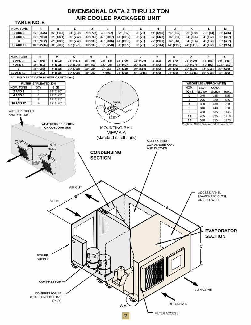
DIMENSIONAL DATA 2 THRU 12 TON AIR COOLED PACKAGED UNIT
12
NOM. TONS N P Q R S T U V W X Y Z2 AND 3 12" (305) 4" (102) 18" (457) 18" (457) 1.5" (38) 16" (406) 16" (406) 2" (51) 16" (406) 16" (406) 3.5" (89) 9.5" (241)4 AND 5 18" (457) 4" (102) 23" (584) 18" (457) 1.5" (38) 18" (457) 20" (508) 3" (76) 18" (457) 18" (457) 3.5" (89) 12.5" (318)
8 20" (508) 4" (102) 30" (762) 23" (584) 2" (51) 24" (610) 24" (610) 3" (76) 20" (508) 20" (508) 14" (356) 20" (508)10 AND 12 22" (559) 4" (102) 30" (762) 38" (965) 4" (102) 30" (762) 40" (1016) 3" (76) 24" (610) 40" (1016) 20" (508) 16" (406)
ALL BOLD FACE DATA IN METRIC UNITS (mm)
NOM. TONS A B C D E F G H J K L M2 AND 3 62" (1575) 45" (1143) 24" (610) 29" (737) 30" (762) 32" (813) 3" (76) 49" (1245) 24" (610) 26" (660) 2.5" (64) 14" (356)4 AND 5 82" (2083) 52" (1321) 30" (762) 30" (762) 42" (1067) 40" (1016) 3" (76) 56" (1422) 36" (914) 34" (864) 4" (102) 18" (457)
8 80" (2032) 72" (1829) 30" (762) 38" (965) 40" (1016) 40" (1016) 3" (76) 76" (1930) 34" (864) 34" (864) 4" (102) 18" (457)10 AND 12 100" (2286) 80" (2032) 50" (1270) 38" (965) 50" (1270) 50" (1270) 3" (76) 86" (2184) 44" (1118) 44" (1118) 4" (102) 38" (965)
WEIGHT LBS (APPROXIMATE)NOM. EVAP. COND.
TONS SECTION SECTION TOTAL
2 240 285 5253 275 320 5954 330 430 7605 340 440 7808 460 685 114510 485 725 121012 520 755 1275
Weight For MKC Is Same As That Of Evap. Section
TABLE NO. 6
WATER PROOFEDAND PAINTED
WEATHERIZED OPTIONON OUTDOOR UNIT
10”
10”
SCREEN GUARD
RAIN HOOD
MOUNTING RAILVIEW A-A
(standard on all units)
0.75''
5/8''Ø
1.625''
2''
13
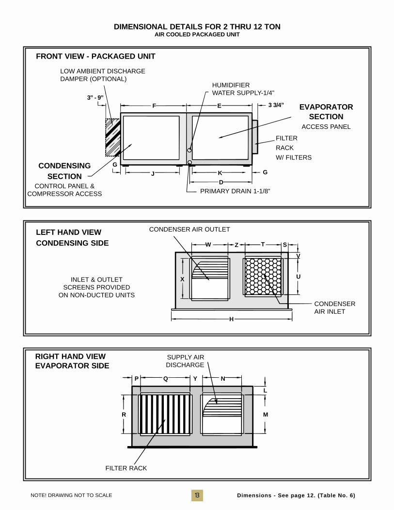
LEFT HAND VIEWCONDENSING SIDE
RIGHT HAND VIEWEVAPORATOR SIDE
FRONT VIEW - PACKAGED UNIT
DIMENSIONAL DETAILS FOR 2 THRU 12 TONAIR COOLED PACKAGED UNIT
W T S
V
UX
P Q Y N
L
MR
H
Z
INLET & OUTLETSCREENS PROVIDED
ON NON-DUCTED UNITSCONDENSERAIR INLET
FILTER RACK
SUPPLY AIRDISCHARGE
HUMIDIFIERWATER SUPPLY-1/4”
LOW AMBIENT DISCHARGEDAMPER (OPTIONAL)
CONDENSINGSECTION
CONTROL PANEL &COMPRESSOR ACCESS
FILTER
RACK
W/ FILTERS
PRIMARY DRAIN 1-1/8”
CONDENSER AIR OUTLET
NOTE! DRAWING NOT TO SCALE
F E
J
G
3” - 9”3 3/4”
K
D
G
Dimensions - See page 12. (Table No. 6)
EVAPORATOR SECTION
ACCESS PANEL
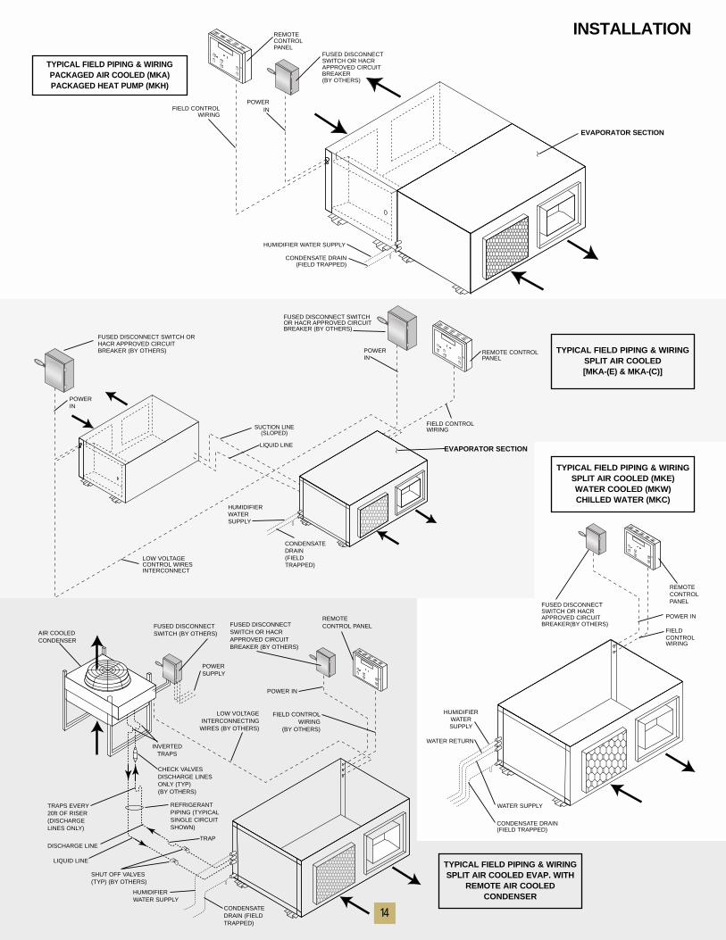
INSTALLATION
TYPICAL FIELD PIPING & WIRINGSPLIT AIR COOLED[MKA-(E) & MKA-(C)]
FUSED DISCONNECT SWITCHOR HACR APPROVED CIRCUITBREAKER (BY OTHERS)
REMOTE CONTROLPANEL
FIELD CONTROLWIRING
CONDENSATEDRAIN(FIELDTRAPPED)
HUMIDIFIERWATERSUPPLY
LOW VOLTAGECONTROL WIRESINTERCONNECT
POWER IN
POWER IN
SUCTION LINE(SLOPED)
LIQUID LINEEVAPORATOR SECTION
FUSED DISCONNECT SWITCH ORHACR APPROVED CIRCUITBREAKER (BY OTHERS)
FUSED DISCONNECTSWITCH OR HACRAPPROVED CIRCUITBREAKER(BY OTHERS)
REMOTECONTROLPANEL
POWER IN
FIELDCONTROLWIRING
HUMIDIFIERWATERSUPPLY
WATER RETURN
WATER SUPPLY
CONDENSATE DRAIN(FIELD TRAPPED)
AIR COOLEDCONDENSER
FUSED DISCONNECTSWITCH (BY OTHERS)
POWERSUPPLY
FUSED DISCONNECTSWITCH OR HACRAPPROVED CIRCUITBREAKER (BY OTHERS)
REMOTECONTROL PANEL
POWER IN
FIELD CONTROLWIRING
(BY OTHERS)
LOW VOLTAGEINTERCONNECTING
WIRES (BY OTHERS)
INVERTEDTRAPS
CHECK VALVESDISCHARGE LINESONLY (TYP) (BY OTHERS)
REFRIGERANTPIPING (TYPICALSINGLE CIRCUITSHOWN)
TRAPS EVERY20ft OF RISER(DISCHARGELINES ONLY)
DISCHARGE LINE
SHUT OFF VALVES(TYP) (BY OTHERS)
HUMIDIFIERWATER SUPPLY
CONDENSATEDRAIN (FIELDTRAPPED)
LIQUID LINE
TRAP
TYPICAL FIELD PIPING & WIRINGSPLIT AIR COOLED (MKE)WATER COOLED (MKW)CHILLED WATER (MKC)
TYPICAL FIELD PIPING & WIRINGSPLIT AIR COOLED EVAP. WITH
REMOTE AIR COOLEDCONDENSER
TYPICAL FIELD PIPING & WIRINGPACKAGED AIR COOLED (MKA)PACKAGED HEAT PUMP (MKH)
CONDENSATE DRAIN(FIELD TRAPPED)
FUSED DISCONNECTSWITCH OR HACRAPPROVED CIRCUITBREAKER(BY OTHERS)
FIELD CONTROLWIRING
HUMIDIFIER WATER SUPPLY
POWERIN
REMOTECONTROLPANEL
EVAPORATOR SECTION
14
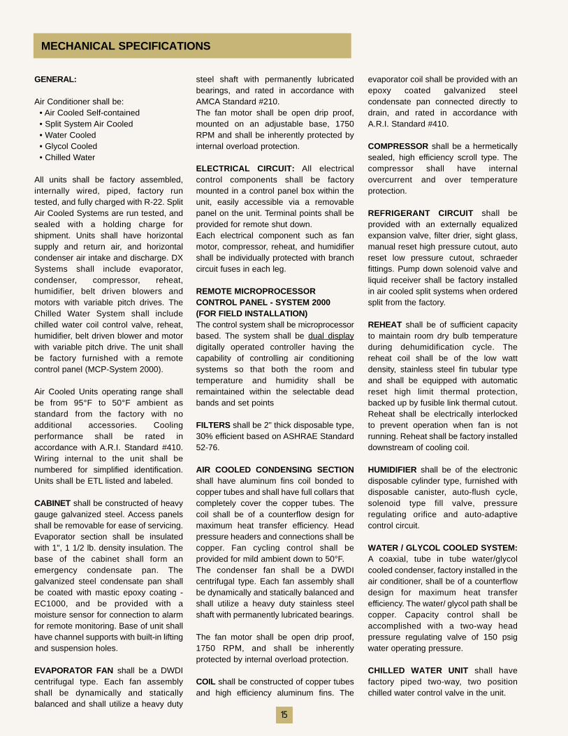
GENERAL:
Air Conditioner shall be:• Air Cooled Self-contained• Split System Air Cooled• Water Cooled• Glycol Cooled• Chilled Water
All units shall be factory assembled,internally wired, piped, factory runtested, and fully charged with R-22. SplitAir Cooled Systems are run tested, andsealed with a holding charge forshipment. Units shall have horizontalsupply and return air, and horizontalcondenser air intake and discharge. DXSystems shall include evaporator,condenser, compressor, reheat,humidifier, belt driven blowers andmotors with variable pitch drives. TheChilled Water System shall includechilled water coil control valve, reheat,humidifier, belt driven blower and motorwith variable pitch drive. The unit shallbe factory furnished with a remotecontrol panel (MCP-System 2000).
Air Cooled Units operating range shallbe from 95°F to 50°F ambient asstandard from the factory with noadditional accessories. Coolingperformance shall be rated inaccordance with A.R.I. Standard #410.Wiring internal to the unit shall benumbered for simplified identification.Units shall be ETL listed and labeled.
CABINET shall be constructed of heavygauge galvanized steel. Access panelsshall be removable for ease of servicing.Evaporator section shall be insulatedwith 1", 1 1/2 lb. density insulation. Thebase of the cabinet shall form anemergency condensate pan. Thegalvanized steel condensate pan shallbe coated with mastic epoxy coating -EC1000, and be provided with amoisture sensor for connection to alarmfor remote monitoring. Base of unit shallhave channel supports with built-in liftingand suspension holes.
EVAPORATOR FAN shall be a DWDIcentrifugal type. Each fan assemblyshall be dynamically and staticallybalanced and shall utilize a heavy duty
steel shaft with permanently lubricatedbearings, and rated in accordance withAMCA Standard #210.The fan motor shall be open drip proof,mounted on an adjustable base, 1750RPM and shall be inherently protected byinternal overload protection.
ELECTRICAL CIRCUIT: All electricalcontrol components shall be factorymounted in a control panel box within theunit, easily accessible via a removablepanel on the unit. Terminal points shall beprovided for remote shut down.Each electrical component such as fanmotor, compressor, reheat, and humidifiershall be individually protected with branchcircuit fuses in each leg.
REMOTE MICROPROCESSOR CONTROL PANEL - SYSTEM 2000 (FOR FIELD INSTALLATION)The control system shall be microprocessorbased. The system shall be dual displaydigitally operated controller having thecapability of controlling air conditioningsystems so that both the room andtemperature and humidity shall beremaintained within the selectable deadbands and set points
FILTERS shall be 2" thick disposable type,30% efficient based on ASHRAE Standard52-76.
AIR COOLED CONDENSING SECTIONshall have aluminum fins coil bonded tocopper tubes and shall have full collars thatcompletely cover the copper tubes. Thecoil shall be of a counterflow design formaximum heat transfer efficiency. Headpressure headers and connections shall becopper. Fan cycling control shall beprovided for mild ambient down to 50°F.The condenser fan shall be a DWDIcentrifugal type. Each fan assembly shallbe dynamically and statically balanced andshall utilize a heavy duty stainless steelshaft with permanently lubricated bearings.
The fan motor shall be open drip proof,1750 RPM, and shall be inherentlyprotected by internal overload protection.
COIL shall be constructed of copper tubesand high efficiency aluminum fins. The
MECHANICAL SPECIFICATIONS
evaporator coil shall be provided with anepoxy coated galvanized steelcondensate pan connected directly todrain, and rated in accordance withA.R.I. Standard #410.
COMPRESSOR shall be a hermeticallysealed, high efficiency scroll type. Thecompressor shall have internalovercurrent and over temperatureprotection.
REFRIGERANT CIRCUIT shall beprovided with an externally equalizedexpansion valve, filter drier, sight glass,manual reset high pressure cutout, autoreset low pressure cutout, schraederfittings. Pump down solenoid valve andliquid receiver shall be factory installedin air cooled split systems when orderedsplit from the factory.
REHEAT shall be of sufficient capacityto maintain room dry bulb temperatureduring dehumidification cycle. Thereheat coil shall be of the low wattdensity, stainless steel fin tubular typeand shall be equipped with automaticreset high limit thermal protection,backed up by fusible link thermal cutout.Reheat shall be electrically interlockedto prevent operation when fan is notrunning. Reheat shall be factory installeddownstream of cooling coil.
HUMIDIFIER shall be of the electronicdisposable cylinder type, furnished withdisposable canister, auto-flush cycle,solenoid type fill valve, pressureregulating orifice and auto-adaptivecontrol circuit.
WATER / GLYCOL COOLED SYSTEM:A coaxial, tube in tube water/glycolcooled condenser, factory installed in theair conditioner, shall be of a counterflowdesign for maximum heat transferefficiency. The water/ glycol path shall becopper. Capacity control shall beaccomplished with a two-way headpressure regulating valve of 150 psigwater operating pressure.
CHILLED WATER UNIT shall havefactory piped two-way, two positionchilled water control valve in the unit.
15
AT&T • PACIFIC BELL • NORTEL NETWORKS • LUCENT TECHNOLOGY • ERICSSON T.I. • QUESTCOMMUNICATION • CARL ZEISS • SNET • IXC COMMUNICATIONS • MVX COMMUNICATIONS • AOL • CISCOSYSTEMS • LOS ALAMITOS NATIONAL LABORATORIES • UNIVERSITY OF WISCONSIN • E.F.HUTTON •EQUITABLE LIFE INSURANCE • PRINCETON UNIVERSITY • DEPARTMENT OF ENERGY • UNIVERSITY OFMISSOURI • DISNEY CORPORATION • MARTIN MARIETTA • THIOKOL CORPORATION • UNIVERSITY OFCALIFORNIA • FEDERAL AVIATION ADMINISTRATION • NATIONAL STEEL CORPORATION • UNIVERSITY OFARIZONA • VETERANS ADMINI-STRATION HOSPITALS • SANDIA CORPORATION • CIBA-GEIGY CORPORATION• DEPARTMENT OF NAVY RAYTHEON CORPORATION • AMOCO-UNISYS CORPORATION • UNIVERSITY OFHOUSTON • BUREAU OF LAND MANAGEMENT • GENERAL SERVICES ADMINISTRATION • BURLINGTONNORTHERN RAILROAD • UNITED STATES POST OFFICE • CIGNA CORP • US AIR FORCE ACADEMY •UNIVERSITY OF NEWMEXICO DATAGENERAL CORP. • JETP R O P U L S I O NLABORATORIES • ITTCANNON INC.GENERAL ELECTRICUNIVERSAL STUDIOSLORD & TAYLOR CO.VANDENBERG AFB NYLIFE INSURANCEMERRILL LYNCH INC.STATE OF TEXASGOOD YEAR TIRE INC.AVIS RENT-A-CARTHE PENTAGONCONOCO CORP. BLUECROSS/BLUE SHIELD •MACY’S CORPORATION • MCDONNELLDOUGLAS CORP. • WEYERHAEUSER CORP. • BELL & HOWELL INC. •FISHER CONTROLS, INC. • UNIVERSITY OF MONTREAL • HOSPITSAL CORP. OF AMERICA • UNIVERSITY OFTENNESSEE • DEPARTMENT OF THE INTERIOR • ROYAL BANK OF CANADA ALLSTATE INSURANCE CO. •ARMAND HAMMER MUSEUM • OWENS CORNING CORP • FORD AEROSPACE CORP. • US ARMY CORPS OFENGINEERS • DEPARTMENT OF DEFENSE • MITSUBISHI ELECTRONICS • WHITE SAND MISSLE RANGE •BOEING CORPORATION • INGERSOL RAND CORP • GTE INC. • AT&T INC. IBM CORP. SEIMENS INC. • XEROXCORP. • ELGIN AFB • KELLYAFB • US WEST INC. • HOLLAMAN AFB • HUGHES CORP. FALCON AFB • AC DELCOCO. • TOYOTA CORP. • PACIFIC BELL • LTV STEEL • SYNTEC CORP. KIRTLAND AFB • SUN MICROSYSTEM •HEWLETT PACKARD • TEXAS INSTRUMENTS • EXODUS COMMUNICATIONS • BRIADCOM • SDL OPTICS •MORGAN STANLEY DEAN WHITTER • CON EDISON • EXCITE@HOME • ARTHUR ANDERSON • PRICE WATERHOUSE
FIRST INTERSTATEBANK • MCCLELLANAFB • NASA • MOBIL OILMOTOROLA CORP.SHELL OIL • IRSGENERAL MOTORSDELTA AIRLINES BANKOF AMERICA PRIMEC O M P U T E RHONEYWELL INC.GENERAL DYNAMICSJ. C. PENNEY INC.BECHTEL CORP.ROCKWELL INT’LFORD MOTOR CO.DITIGAL CORP. •WELLS FARGO BANKLOCKHEED CORP.D
While every precaution has beentaken to ensure accuracy andcompleteness in this brochure,Compu-Aire, Inc. assumes noresponsibility and disclaims allliability for damages resultingfrom use of this information or forany errors or ommissions.Subject to change without notice.
Printed in the U.S.A.
8167 Byron RoadWhittier, CA 90606-2615(562) 945-8971 phone(562) 696-0724 faxweb site: www.compu-aire.com
4/02 5M TAB 3
A COMPANY IS MEASURED –BY THE COMPANY IT KEEPS –
M i n o r i t y B u s i n e s s E n t e r p r i s e