Embed Size (px)
Citation preview
146197-01 - 01-2019
Manufactured by OSO Hotwater ASIndustriveien 1 - 3300 Hokksund - NorwayTel: + 47 32 25 00 00 / Fax: + 47 32 25 00 90E-mail: [email protected] / www.osohotwater.com
Maxi Geocoil - MGC600-1000 l.
EN
SAFETY INFORMATIONO&M INFORMATIONINSTALLATION MANUALTDS - TECHNICAL DATA SHEET

2
CONTENTS 1. Safety instructions .................................................... 3 1.1 General information......................................... 3 1.2 Safety instructions for users ........................ 4 1.3 Safety instructions for installers ................. 4
2. Product description ................................................. 5 2.1. Product identification ..................................... 5 2.2. Intended use ...................................................... 5 2.3 CE marking ......................................................... 5 2.4 Technical data ..................................................... 5 2.5. ErP data (TDS) ..................................................... 5
3. Installation instructions ........................................ 6 3.1. Products covered by these instructions 6 3.2. Included in delivery .......................................... 6 3.3. Product dimensions ......................................... 6 3.4. Requirements for installation location . 7 3.5. Pipe installation .................................................. 8 3.6. Electrical installation ...................................... 10
4. Initial commissioning ............................................ 12 4.1. Filling with water .............................................. 12 4.2. Turning on the power ................................... 12 4.3. Control points ................................................... 12 4.4. Emptying of water .......................................... 12 4.5. Handover to end-user .................................. 12
5. User Guide .................................................................... 13 5.1. Settings ................................................................. 13 5.2. Maintenance ...................................................... 13
6. Troubleshooting ...................................................... 14 6.1. Faults and fixes ................................................. 14
7. Warranty conditions ............................................. 15 7.1. Warranty and registration .......................... 15 7.2. Customer service ............................................. 15
8. Removing the product ........................................ 15 8.1. Removal................................................................ 15 8.2. Returns scheme................................................ 15

3
1. SAFETY INSTRUCTIONS 1.1 General information• Read the following safety instructions
carefully before installing, maintaining or adjusting the buffer tank.
• Personal injury or material damage may result if the product is not installed or used in the intended manner.
• Keep this manual and other relevant doc-uments where they are accessible for fu-ture reference.
• The manufacturer assumes compli-ance (by the end-user) with the safety, operating and maintenance instructions supplied and (by the installer) with the fit-ting manual and relevant standards and regulations in effect at the date of instal-lation.
Symbols used in this manual:
! WARNING Could cause serious injury or death
! CAUTION Could cause minor or moderate injury or damage to property
DO NOT
! DO
! This document should be kept in a suitable place where it is accessible for future reference.
!
4
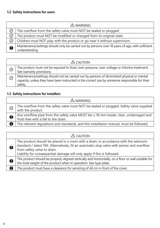
1.3 Safety instructions for installers
! WARNING
The overflow from the safety valve must NOT be sealed or plugged. Safety valve supplied with the product
! Any overflow pipe from the safety valve MUST be > 18 mm inside, clear, undamaged and frost-free with a fall to the drain.
! The relevant regulations and standards, and this installation manual, must be followed.
1.2 Safety instructions for users
! WARNING
The overflow from the safety valve must NOT be sealed or plugged.The product must NOT be modified or changed from its original state.Children must NOT play with the product or go near it without supervision.
! Maintenance/settings should only be carried out by persons over 18 years of age, with sufficient understanding
! CAUTIONThe product must not be exposed to frost, over-pressure, over-voltage or chlorine treatment. See warranty provisions.Maintenance/settings should not be carried out by persons of diminished physical or mental capacity, unless they have been instructed in the correct use by someone responsible for their safety.
! CAUTION
!The product should be placed in a room with a drain, in accordance with the wetroom standard / latest TEK. Alternatively, fit an automatic stop valve with sensor and overflow from safety valve to drain. Liability for consequential damage will only apply if this is followed.
! The product should be properly aligned vertically and horizontally, on a floor or wall suitable for the total weight of the product when in operation. See type plate.
! The product must have a clearance for servicing of 40 cm in front of the cover.

5
2.4 Technical data
NRF no. Product code: Capacitypersons
Weightkg.
Diameter x heightmm
Freight vol. m³
Heating time, hours Dt 65°C
Actualvol. l.
800 1853 MGC 600 - 15 kW / 3x230V + HX 4.6 m² - 160 ø780x1900 1.28 - 534800 1854 MGC 1000 - 15 kW / 3x230V + HX 4.6 m² - 265 ø1000x2100 2.29 - 877
2.5 ErP data - Technical Data Sheet
Brand Model-no. Model name ErP profile
ErP rating AEC - kWh/a
Thermo-stat set-ting °C
Volume 40°C water
Heat loss W
OSO Hotwater AS 800 1853 MGC 600 - C - 75 - 118OSO Hotwater AS 800 1854 MGC 1000 - C - 75 - 141
Directive: 2010/30/EU Regulation: EU 812/2013 Directive: 2009/125/EC Regulation: EU 814/2013
Heat loss tested acc. to standard: EN 12897: 2015
2. PRODUCT DESCRIPTION 2.1 Product identificationIdentification details for your product can be found on the type plate fixed to the product. The type plate contains details of the product in accordance with EN 12897:2016 and EN 60335-2-21, as well as other useful data. See Declaration of Conformity at www.osohotwater.com for more information.
OSO products are designed and manufactured in accordance with:• Pressure vessel standard PED 2014/68/EU• Safety standard EN 60335-2-21• Welding standard EN ISO 3834-2
OSO Hotwater AS is certified for • Quality ISO 9001• Environment ISO 14001• Work environment OHSAS 18001
2.2 Intended useThe Maxi Geocoil is designed for use as a buffer for tap water at electrical peak load. The MGC is fitted for external energy sources.
2.3 CE marking
The CE mark shows that the product complies with the relevant Directives. See Declaration of Conformity at www.osohotwater.com for more information.
The product complies with EU Directives for:• Low voltage LVD 2014/35/EU• Electromagnetic compatibility EMC 2014/30/EU• Pressurised equipment PED 2014/68/EU
The safety valve(s) used must be CE marked and conform to PED 2014/68/EU.
6
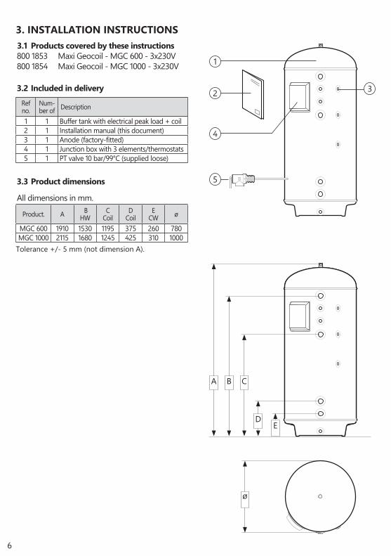
3.3 Product dimensions
Product. A B HW
CCoil
DCoil
E CW ø
MGC 600 1910 1530 1195 375 260 780MGC 1000 2115 1680 1245 425 310 1000
Tolerance +/- 5 mm (not dimension A).
3. INSTALLATION INSTRUCTIONS 3.1 Products covered by these instructions800 1853 Maxi Geocoil - MGC 600 - 3x230V800 1854 Maxi Geocoil - MGC 1000 - 3x230V
3.2 Included in delivery
Ref no.
Num-ber of Description
1 1 Buffer tank with electrical peak load + coil2 1 Installation manual (this document)3 1 Anode (factory-fitted)4 1 Junction box with 3 elements/thermostats5 1 PT valve 10 bar/99°C (supplied loose)
2
5
1
4
3
All dimensions in mm.
DE
A B C
ø

7
3.3.1 Delivery
The product should be transported carefully as shown, with packaging.
! CAUTION
Pipe stubs, valves etc. should not be used to lift the product as this could cause malfunctions.
3.4 Requirements for installation location and positioning
! CAUTION
!The product should be placed in a room with a drain, in accordance with the wetroom standard / latest TEK. Alternatively, fit an automatic stop valve with sensor and overflow from safety valve to drain.
! The product should be placed in a dry and permanently frost-free position.
! The product should be placed on a floor or wall suitable for the total weight of the product when in operation. See type plate.
! The product must have a clearance for servicing of 40 cm in front of the cover.
! The product should be easily accessible for servicing and maintenance.
Min. 40 cm
Min. 40 cm

8
No. Dimension Connection description
1 1½” internal thread. Hot water out2 3/4” internal thread. PT valve3 3/4” internal thread. Hot water circulation4 1 ½” int. thread Coil connection, upper5 3/4” internal thread. Anode6 ½” internal thread Sensor slot7 ½” internal thread Sensor slot8 1 ½” int. thread Coil connection, lower9 1½” internal thread. Cold water in10 1” int. thread Draining
3.5 Pipe installation
3.5.1 Incoming water pressureThe efficiency of the product depends on the in-coming cold water pressure. The water pressure should be min. 2 bar and max. 6 bar throughout the day. Excessive water pressure can be adjusted by installing a pressure reduction valve.
3.5.2 Fitting pipesA) Run a pipe of suitable size to the connec-
tions shown, and affix with suitable sealant. Unused connections must be plugged se-curely.
B) The product can connected in series for increased capacity in the system. Use OSO prefabricated SRS manifolds. See illustra-tion.
3.5.3 Fitting of overflow pipeOverflow pipe (12) > 18 mm inside run to PT safety valve;• Connected to the overflow (11) of the PT
safety valve (3/4” internal thread).• Clear, undamaged and frost-free with a
fall to the drain.
The product is designed to be permanently con-nected to the mains water supply. Approved pipes of the correct size should be used for installation. The relevant standards and regulations must be followed.
123
4
5
6
7
8
10
9
12
12
11

9
RECOMMENDATION
-If the maximum water pressure exceeds 6 bar in a 24-hour period, a reduction valve and expansion vessel should be fitted.
-For installation in a rooms which does not conform to the wetroom standard, a watertight drip tray with overflow pipe > 18 mm. inside diameter should be fitted under the product, in addition to an automatic stop cock with sensor. This will prevent possible material damage.
3.5.4 Fitting instructions
3.5.5 Fitting recommendation
! CAUTION
!The product should be placed in a room with a drain, in accordance with the wetroom standard / latest TEK. Alternatively, fit an automatic stop valve with sensor and overflow from safety valve to drain.
! The product should be properly aligned vertically and horizontally, on a floor suitable for the total weight of the product when in operation. See type plate.
! The product must have a clearance for servicing of 40 cm in front of the cover.

10
RESET RESET
M2
1
2
3
4
THERM-O-DISC
1
2
RESET RESET
M2
1
2
3
4
THERM-O-DISC
1
2
RESET RESET
M2
1
2
3
4
THERM-O-DISC
1
2
L1L2 L3
L1 L1L2 L2L3 L3
Electrical connection, diagram3x5 kW - 3x230V / 3x400V
3.6.3 Torque settings! WARNING
Constant voltage present at the terminals. Be-fore any electrical work is done, the power sup-ply must be disconnected and secured against activation while the work is in progress.
Component Torque5/4” heating element 60 Nm (+/- 5)Thermostat screws 2 Nm (+/- 0.1)Screw on the element head 2 Nm (+/- 0.1)
A) Supply cable connected to Ensto terminal (1) as shown. Supply wires should be secured with suitable strain relievers.
B) Internal wires from connection piece (1) to thermostats and the wires from thermostats to elements are pre-connected from the factory.
C) Make sure that the earth wire (yellow wire with green stripe) is connected to the earthing point
Cover of junction box should be correctly mount-ed before the power is switched on. The power must not be switched on until the product has been filled with water.
3.6 Electrical installation
3.6.1 Electrical components
Component NoteSafety thermostat 98°C thermal cut-outWork thermostat 60-90°C adjustableHeating element 3-phase 230 VInternal wires Heat-resistant
Fixed electrical fittings must be used for instal-lation. Any electric fittings must be installed by an authorised electrician. The relevant standards and regulations must be followed.
3.6.2 Electrical connections in the junction box
1
Circuit diagram shows stand-ard connection from the factory (3x230V), and also applies to 3x400V (elements need to be changed to 415V).
11
RESET RESET
M2
1
2
3
4
THERM-O-DISC
1
2
RESET RESET
M2
1
2
3
4
THERM-O-DISC
1
2
RESET RESET
M2
1
2
3
4
THERM-O-DISC
1
2
L1L2
0
L3
L1 L1L2 L2L3 L3
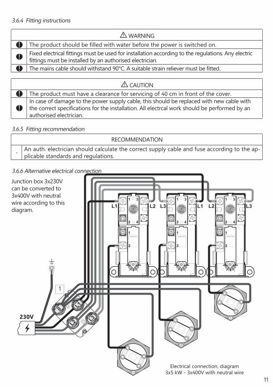
Electrical connection, diagram3x5 kW - 3x400V with neutral wire
RECOMMENDATION
- An auth. electrician should calculate the correct supply cable and fuse according to the ap-plicable standards and regulations.
3.6.4 Fitting instructions
3.6.5 Fitting recommendation
! WARNING
! The product should be filled with water before the power is switched on.
! Fixed electrical fittings must be used for installation according to the regulations. Any electric fittings must be installed by an authorised electrician.
! The mains cable should withstand 90°C. A suitable strain reliever must be fitted.
! CAUTION
! The product must have a clearance for servicing of 40 cm in front of the cover.
!In case of damage to the power supply cable, this should be replaced with new cable with the correct specifications for the installation. All electrcal work should be performed by an authorised electrician.
1
230V
Junction box 3x230V can be converted to 3x400V with neutral wire according to this diagram.
3.6.6 Alternative electrical connection
12
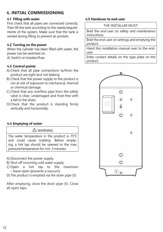
4.1 Filling with waterFirst check that all pipes are connected correctly. Then fill the tank according to the needs/require-ments of the system. Make sure that the tank is vented during filling to prevent air pockets.
4.2 Turning on the powerWhen the cylinder has been filled with water, the power can be switched on. A) Switch on breaker/fuse.
4.3 Control pointsA) Check that all pipe connections to/from the
product are tight and not leaking.B) Check that the power supply to the product is
not at risk of exposure to mechanical, thermal or chemical damage.
C) Check that any overflow pipe from the safety valve is clear, undamaged and frost-free with a fall to the drain.
D) Check that the product is standing firmly vertically and horizontally.
4.5 Handover to end-user
4. INITIAL COMMISSIONING
THE INSTALLER MUST:
Brief the end-user on safety and maintenance instructions.Brief the end-user on settings and emptying the product.Hand this installation manual over to the end-user.Enter contact details on the type plate on the product.
! WARNING
The water temperature in the product is 75°C and could cause scalding. Before empty-ing, a hot tap should be opened to the max. pressure/temperature for min. 3 minutes.
A) Disconnect the power supply.B) Shut off incoming cold water supply.C) Open a hot tap to the maximum
– leave open (prevents a vacuum).D) The product is emptied via the drain pipe (5)
After emptying, close the drain pipe (5). Close all open taps.
4.4 Emptying of water
5
2

13
! WARNING
Constant voltage present in the junction box. Be-fore any electrical work is done, the power supply must be disconnected and secured against acti-vation while the work is in progress.
5.2 Maintenance
5.1 Settings5.1.1 Thermostat settingThe product’s thermostats are adjustable from 60-90°C. The thermostat should not be set lower than 65°C to prevent bacteria growth. To adjust the temperature:A) Disconnect the power supply.B) Remove the cover (2) with a screwdriver.C) Adjust the temperature on the thermostats (3)
with a screwdriver.
Fit the cover (2) before connecting the power sup-ply.
5.1.2 Resetting the safety thermostatThe safety thermostats on the product cut out when there is a risk of overheating. Tese are is reset by switching off the power supply, removing the cov-er (2) and pressing the red ‘RESET’ button (4). If the thermostat cuts out repeatedly, contact the in-staller.
5. USER GUIDE
RESET RESET
M2
1
2
3
4
THERM-O-DISC
60°C90°C
80°C 70°C
1
2
3
4
MAINTENANCE INSTRUCTIONS
! Maintenance should be carried out by persons over 18 years of age, with suf-ficient understanding.
! Annual inspection of safety valve:
- Open valve for 1 min. by turning the knob (1) approx. 90 degrees to the open position.
- Visually check that the water is flowing freely to the drain.
- YES = OK. Close the valve by pushing the lever (1) down to the closed position.
- NO = NOT OK. Disconnect power supply / shut off water supply. Contact in-staller.
1

14
6.1 Faults and fixesIf problems arise when the product is in use, check for possible faults and fixes in the table.If you are unsure what is wrong, contact the
6. TROUBLESHOOTING
TROUBLESHOOTINGProblem Possible cause of fault Possible solution
There is leakage/drip-ping from the safety valve/there is often water on the floor by the cylinder in the morning
Pressure reduction valve, water meter or blocked non-return valve on the water intake.
Water pressure into the system is too high.
Fit AX expansion vessel which absorbs expansion during heating, and fit pressure reduction valve for stable water pressure inside the system. The pressure reduction valve is adjusted in according to the pressure in the expansion vessel. Contact auth. installer.
The safety valve is worn or there are particles stuck between the mem-brane and the valve seat because the water is dirty
Try to flush with water through the safety valve. Open valve for approx. 1 minute. See section 5.2. If the valve still leaks, it must be replaced. Contact auth. installer.
Leak from heating element.
Verify as follows: a) cut the electric sup-ply, b) unscrew the cover, c) visually check whether there is a leak from the heating element. If so, replace the gasket/heating element. Contact auth. installer.
No hot water
Power supply interrupted.Verify that the fuse is on / the plug is plugged in to the wall contact / the earth breaker has not tripped.
Thermostat has cut out. Press the ‘RESET’ button on the safety thermostat; see ‘User guide’.
Heating element is defective. Replace heating element. Contact auth. installer.
Leak in hot water pipe
Verify as follows: a) close the water sup-ply, b) wait 2-3 hours, c) feel the tank to see whether it is hot. If so, there is a leak in the hot water pipe or elsewhere. Con-tact auth. installer.
Not enough hot water High consumption in the system. Switch to a larger OSO water heater. Contact auth. installer.
Not high enough temperature
The thermostat is set for low temperatures.
Check the thermostat settings. Turn up to 75°C; see ‘User guide’.
Change from cold to hot water in taps. Contact auth. installer.
Fuse/earth breaker trips repeatedly
Possible fault in the heater’s electri-cal system.
Verify as follows: a) cut the electric supply, b) unscrew the cover, c) visually check the junction box for any problems. If so, con-tact auth. installer to check. Fit the cover.
Long time before the water reaches the tap
Long stretch of pipe from water heater to tap.
Fit circulation wire or heating cable to HW pipe. Or fit an auxiliary heater by the tap. Contact auth. installer.
Knocking in the pipes when the hot tap is closed
Large pressure increase when the tap is closed quickly.
Completely normal. Fit AX expansion vessel if troublesome. Contact auth. installer.
installer (see product type plate) or OSO Hot-water AS - see section 7.1.

15
7.1 Customer serviceIn case of problems that cannot be resolved with the aid of the troubleshooting guide in this installation manual, contact either:A) The installer who supplied the product. B) OSO Hotwater AS: Tel.: +47 32 25 00 00
[email protected] / www.oso.no
7. WARRANTY CONDITIONS
8. REMOVING THE PRODUCT
8.1 RemovalA) Disconnect the power supply.B) Shut off incoming cold water supply.C) Empty the product of water – see section 4.4.
100%
1. ScopeOSO Hotwater AS (hereinafter called OSO) warrants for 2 years from the date of purchase, that the Product will: i) conform to OSO specification, ii) be free from defects in materials and workmanship, subject to conditions below. All components carry a 2-year warranty. The warranty is voluntarily extended by OSO to 5 years for the stainless steel inner tank. This extended warranty only applies to Products purchased by a consumer, that has been installed for private use and that has been distributed by OSO or by a distributor where the Products have been originally sold by OSO.The extended warranty does not apply to Products purchased by commercial entities or for Products that have been installed for commercial use. These shall be subject only to the mandatory provisions of the law. The conditions and limitations set out below shall apply.
2. CoverageIf a defect arises and a valid claim is received within the statutory warranty period, at its option and to the extent permitted by law, OSO shall either; i) repair the defect, or; ii) replace the product with a product that is identical or similar in function, or; iii) refund the purchase price.If a defect arises and a valid claim is received after the statutory warranty period has expired, but within the extended warranty period, OSO will supply a product that is identical or similar in function. OSO will in such cases not cover any other associated costs. Any exchanged Product or component will become the legal property of OSO. Any valid claim or service does not extend the original warranty. The replacement Product or part does not carry a new warranty.
3. ConditionsThe Product is manufactured to suit most public water supplies. However, there are certain water chemistries (outlined below) that can have a detrimental effect on the Product and its life expectancy. If there are uncertainties regarding water quality, the local water supply authority can supply the necessary data.The warranty applies only if the conditions set out below are met in full:• The Product has been installed by a professional installer,
in accordance with the instructions in the installation manual and all relevant Codes of Practice and Regulations in force at the time of installation.
• The Product has not been modified in any way, tampered with or subjected to misuse and no factory fitted parts have been removed for unauthorized repair or replacement.
• The Product has only been connected to a domestic mains water supply in compliance with the European Drinking Water Directive EN 98/83 EC, or latest version. The water
should not be aggressive, i.e. the water chemistry shall comply with the following:
- Chloride < 250 mg / L - Electric Conductivity (EC) @25°C < 750 uS / cm - Saturation Index (LSI) @80°C > - 1,0 / < 0,8 - pH level > 6,0 / < 9,5
• The immersion heater has not been exposed to hardness levels exceeding 10°dH (180 ppm CaCO3). A water softener is recommended in such cases.
• Any disinfection has been carried out without affecting the Product in any way whatsoever. The Product shall be isolated from any system chlorination.
• The Product has been in regular use from the date of installation. If the Product is not intended to be used for 60 days or more, it must be drained.
• Service and/or repair shall be done according to the installation manual and all relevant codes of practice. Any replacement parts used shall be original OSO spare parts.
• Any third-party costs associated with any claim has been authorized in advance by OSO in writing.
• The purchase invoice and/or installation invoice, a water sample as well as the defective product is made available to OSO upon request.
Failure to follow these instructions and conditions may result in product failure, and water escaping from the Product.
4. LimitationsThe warranty does not cover:• Any fault or costs arising from incorrect installation,
incorrect application, lack of regular maintenance in accordance with the installation manual, neglect, accidental or malicious damage, misuse, any alteration, tampering or repair carried out by a non-professional, any fault arising from the tampering with or removal of any factory fitted safety components or measures.
• Any consequential damage or any indirect loss caused by any failure or malfunction of the Product whatsoever.
• Any pipework or any equipment connected to the Product.• The effects of frost, lightning, voltage variation, lack
of water, dry boiling, excess pressure or chlorination procedures.
• The effects of stagnant (de-aerated) water if the Product has been left unused for more than 60 days consecutively.
• Damage caused during transportation. Buyer shall give the carrier notice of such damage.
• Costs arising if the Product is not immediately accessible for servicing.
These warranties do not affect the Buyer’s statutory rights.
D) Disconnect all pipes.E) The product can now be removed.
8.2 Returns schemeThis product is recyclable and should be taken to the environmental recycling centre. If the product is to be replaced with a new one, the installer can take the old cylinder away for re-cycling.
OSO Hotwater ASIndustriveien 13300 Hokksund - NorwayTel: + 47 32 25 00 [email protected]
© Alle deler av denne montasjeanvisningen er beskyttet av åndsverksloven og skal ikke reproduseres eller distribueres uten skriftlig avtale med produsenten.Forandringer forbeholdes.
© This installation manual and all its content is protected by copyright and may be reproduced or distributed only with written consent from the manufacturer.We reserve the right to make changes without notice.