Embed Size (px)
Citation preview
OPERATING & MAINTENANCE
MAXETM
CENTRIFUGAL LIQUID CHILLERS
Supersedes: 160.73-O2 (1202) Form 160.73-O2 (605)
MODEL YK (STYLE F)R-134a COOLING ONLY
WITH OPTIVIEWTM CONTROL CENTERFOR ELECTRO-MECHANICAL STARTER,
SOLID STATE STARTER & VARIABLE SPEED DRIVE
00611VIP
LDO5842

YORK INTERNATIONAL
FORM 160.73-O2 (605)
2
This equipment is a relatively complicated apparatus. During installation, operation, maintenance or service, in di vid u als may be exposed to certain components or conditions including, but not limited to: refrigerants, oils, materials under pressure, rotating components, and both high and low voltage. Each of these items has the po ten tial, if misused or handled improperly, to cause bodi ly injury or death. It is the obligation and re spon -si bil i ty of operating/service personnel to identify and rec og nize these inherent hazards, protect themselves, and pro ceed safely in completing their tasks. Failure to com ply with any of these requirements could result in se ri ous dam age to the equipment and the property
IMPORTANT!READ BEFORE PROCEEDING!
GENERAL SAFETY GUIDELINESin which it is sit u at ed, as well as severe personal in-jury or death to them selves and people at the site.
This document is intended for use by owner-authorized operating/service personnel. It is expected that this in- di vid u al possesses independent training that will en able them to perform their assigned tasks properly and safe ly. It is essential that, prior to performing any task on this equipment, this individual shall have read and un der -stood this document and any referenced materials. This in di vid u al shall also be familiar with and comply with all ap pli ca ble governmental standards and regulations per tain ing to the task in question.
SAFETY SYMBOLS
The following symbols are used in this document to alert the reader to areas of potential hazard:
WARNING indicates a potentially haz ard ous sit u a tion which, if not avoid ed, could result in death or se- ri ous in ju ry.
DANGER indicates an im mi nent ly hazardous situation which, if not avoid ed, will re sult in death or se ri ous injury.
CAUTION identifi es a hazard which could lead to damage to the ma chine, damage to other equip ment and/or en vi ron men tal pollution. Usually an in struc tion will be given, together with a brief ex pla na tion.
External wiring, unless specifi ed as an optional connection in the man u fac tur er’s prod uct line, is NOT to be connected inside the micro pan el cab i net. De vic es such as re lays, switch es, transducers and controls may NOT be installed inside the mi cro pan el. NO external wiring is al lowed to be run through the micro panel. All wir ing must be in ac cor dance with YORK’s pub lished spec i fi ca tions and must be per formed ONLY by qual i fi ed YORK personnel. YORK will not be re spon si ble for dam ag es/problems re sult ing from im prop er con nec tions to the con trols or ap pli ca tion of im prop er con trol sig nals. Failure to fol low this will void the man u fac tur er’s warranty and cause serious dam age to property or injury to per sons.
NOTE is used to highlight ad di tion al information which may be helpful to you.

FORM 160.73-O2 (605)
3YORK INTERNATIONAL
CHANGEABILITY OF THIS DOCUMENTIt is the responsibility of operating/service personnel as to the applicability of these documents to the equip- ment in question. If there is any question in the mind of op er at ing/service personnel as to the applicability of these documents, then, prior to working on the equip ment, they should verify with the owner wheth er the equipment has been modifi ed and if current lit er a ture is available.
DESIGN LEVEL (F)
POWER SUPPLY – for 60 Hz 5 for 50 Hz
COM PRES SOR CODE H4, H5, H6, H7, H8, H9, J1, J2, J3, J4, J5, P1, P2, P3, P4, P5, P6, P7, P8, P9, Q7 CONDENSER CODE AA, AB, AC, AD, BA, BB, BC, BD, CD, CE, CF, CG, CH, DE, DF, DG, DH, EB, EC, ED, EK, EL, EM, FA, FB, FC, FD, FK, Fl, FM, GB, GC, GD, GJ, GK, GL, GM, HB, HC, HD, HK, HL, HM, JB, JC, JD, KJ, KK, KL, KM, TB, TC, TD , VB, VC, VD, XA, XB, XC, XD EVAPORATOR CODE AA, AB, AC, AD, BA, BB, BC, BD, CD, CE, CF, CG, CH, DE, DF, DG, DH, EB, EK, EL, EM, FB, FC, FD, FK, FL, FM, GB, GC, GD, GF, GH, GJ, GK, GL, GM, HB, HC, HF, HH, HK, HL, HM, JF, JG, JH, KD, KJ, KK, KL, KM, LK, LL, LM, TB, TC, TD, TF, TG, TH, VF, VH, WF, WH, XF, XH
NOMENCLATURE YK CB CB P6 – CM F
MOTOR CODE 60 Hz 50 Hz CH CX 5CE 5CT CJ CY 5CF 5CU CK CZ 5CG 5CV CL CA 5CH 5CW CM CB 5CI 5CX CN DA 5CJ 5DA CP DB 5CK 5DB CR DC 5CL 5DC CS DD 5CM 5DD CT DE 5CN 5DE CU DF 5CO 5DF CV DH 5CP 5DG CW DJ 5CQ 5DH CF CG 5CR 5OJ 5CS
In complying with YORK’s policy for continuous prod- uct improvement, the information contained in this doc- u ment is subject to change without notice. While YORK makes no commitment to update or pro vide current in for ma tion automatically to the manual own er, that in- for ma tion, if applicable, can be ob tained by con tact ing the nearest YORK Applied Systems Service offi ce.
REFERENCE INSTRUCTIONS DESCRIPTION FORM NO.
SOLID STATE STARTER (MOD “B”) – OPERATION & MAINTENANCE 160.00-O2
VARIABLE SPEED DRIVE – OPERATION 160.00-O1
VARIABLE SPEED DRIVE – SERVICE INSTRUCTIONS 160.00-M1
INSTALLATION 160.73-N1
OPTIVIEW CONTROL CENTER - SERVICE INSTRUCTIONS 160-54-M1
WIRING DIAGRAM – UNIT WITH ELECTRO-MECHANICAL STARTER 160.73-PW1
WIRING DIAGRAM – UNIT WITH MOD “A” SOLID STATE STARTER 160.73-PW2
WIRING DIAGRAM – UNIT WITH VARIABLE SPEED DRIVE 160.73-PW3
RENEWAL PARTS – UNIT 160.73-RP4
RENEWAL PARTS – OPTIVIEW CONTROL CENTER 160.54-RP1
OPTIVIEW™ PANEL - OPERATION & MAINTENANCE 160.54.O1
MODEL
YORK INTERNATIONAL
FORM 160.73-O2 (605)
4
SECTION 1 Description of System and Fundamentals of Operation ............................... 6
SECTION 2 System Operating Procedures ...................................................................... 9
SECTION 3 System Components Description ............................................................... 15
SECTION 4 Operational Maintenance ........................................................................... 21
SECTION 5 Troubleshooting .......................................................................................... 23
SECTION 6 Maintenance ............................................................................................... 25
SECTION 7 Preventive Maintenance ............................................................................. 34
TABLE OF CONTENTS
FORM 160.73-O2 (605)
5YORK INTERNATIONAL
LIST OF FIGURES
FIG. 1 – MODEL YK MAXETM CHILLER ................................... 6
DETAIL A – COMPRESSOR PREROTATION VANES .................................................................. 7
FIG. 2 – REFRIGERANT FLOW-THROUGH CHILLER ........... 8
FIG. 3 – OIL LEVEL INDICATOR LABEL .................................. 9
FIG. 4 – CHILLER STARTING SEQUENCE & SHUTDOWN SE QUENCE (EM STARTER & SOLID STATE STARTER) ...... 10
FIG. 5 – CHILLER STARTING SEQUENCE & SHUTDOWN SE QUENCE (VARIABLE SPEED DRIVE) ................................11
FIG. 6 – LIQUID CHILLER LOG SHEETS .............................. 12
FIG. 7 – SYSTEM COMPONENTS ........................................ 15
FIG. 8 – SCHEMATIC DRAWING (YK) COMPRESSOR LUBRICATION SYSTEM .................................... 16
FIG. 9 – OIL RETURN SYSTEM ............................................ 21
FIG. 10 – CHARGING OIL RESERVOIR WITH OIL ............... 22
FIG. 11 – EVACUATION OF CHILLER ................................... 25
FIG. 12 – SATURATION CURVE ............................................ 27
FIG. 13 – DIAGRAM - MEGGING MOTOR WINDINGS ......... 29
FIG. 14 – MOTOR STATOR TEMPERATURE & INSULATION RE SIS TANCE .............................. 30
YORK INTERNATIONAL
FORM 160.73-O2 (605)
6
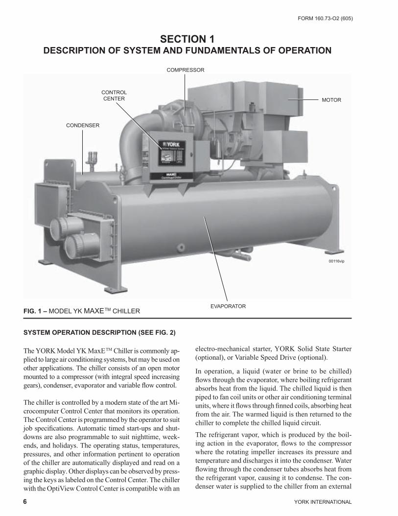
electro-mechanical starter, YORK Sol id State Start er (optional), or Variable Speed Drive (op tion al).
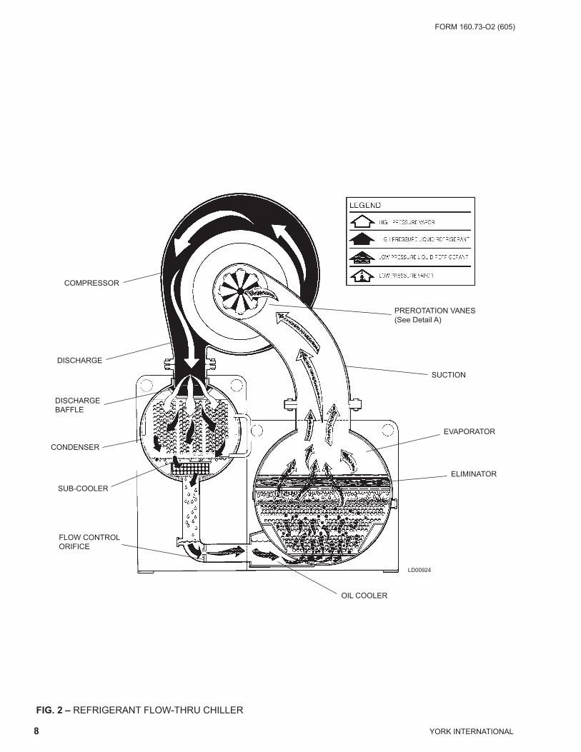
In operation, a liquid (water or brine to be chilled) fl ows through the evaporator, where boiling refrigerant absorbs heat from the liquid. The chilled liquid is then piped to fan coil units or other air conditioning terminal units, where it fl ows through fi nned coils, absorbing heat from the air. The warmed liquid is then returned to the chill er to complete the chilled liquid circuit.
The refrigerant vapor, which is produced by the boil- ing action in the evaporator, fl ows to the compressor where the rotating impeller increases its pressure and tem per a ture and discharges it into the condenser. Water fl ow ing through the condenser tubes absorbs heat from the re frig er ant va por, causing it to condense. The con- dens er water is sup plied to the chiller from an external
SECTION 1DESCRIPTION OF SYSTEM AND FUNDAMENTALS OF OPERATION
00116vip
CONDENSER
CONTROLCENTER
COMPRESSOR
MOTOR
EVAPORATORFIG. 1 – MODEL YK MAXETM CHILLER
SYSTEM OPERATION DESCRIPTION (SEE FIG. 2)
The YORK Model YK MaxETM Chiller is com mon ly ap-plied to large air conditioning systems, but may be used on other applications. The chiller consists of an open mo tor mounted to a compressor (with integral speed in creas ing gears), condenser, evaporator and vari able fl ow control.
The chiller is controlled by a modern state of the art Mi- cro com put er Control Center that monitors its op er a tion. The Control Center is programmed by the op er a tor to suit job specifi cations. Automatic timed start-ups and shut- downs are also programmable to suit night time, week- ends, and holidays. The operating status, tem per a tures, pressures, and other information per ti nent to op er a tion of the chiller are automatically dis played and read on a graph ic display. Other displays can be ob served by press- ing the keys as labeled on the Control Center. The chill er with the OptiView Con trol Center is compatible with an

FORM 160.73-O2 (605)
7YORK INTERNATIONAL
1
source, usually a cool ing tower. The condensed re frig -er ant drains from the con dens er into the liquid return line, where the variable orifi ce meters the fl ow of liquid re frig er ant to the evaporator to com plete the refrigerant cir cuit.
7619A(D)
DETAIL A – COMPRESSOR PREROTATION VANES
Description of System and Fun da men tals of Operation
The major components of a chiller are selected to han dle the refrigerant, which would be evaporated at full load design conditions. However, most systems will be called upon to deliver full load capacity for only a relatively small part of the time the unit is in operation.
CAPACITY CONTROLThe major components of a chiller are selected for full load capacities, therefore capacity must be controlled to maintain a constant chilled liquid temperature leav ing the evaporator. Prerotation vanes (PRV), located at the en trance to the compressor impeller, compensate for vari a tion in load (See Detail A).
The position of these vanes is automatically controlled through a lever arm attached to an electric motor lo cat ed outside the compressor housing. The automatic adjust-ment of the vane position in effect provides the perfor-mance of many different compressors to match various load conditions from full load with vanes wide open to minimum load with vanes completely closed.
YORK INTERNATIONAL
FORM 160.73-O2 (605)
8
FIG. 2 – REFRIGERANT FLOW-THRU CHILLER
PREROTATION VANES(See Detail A)
SUCTION
EVAPORATOR
ELIMINATOR
OIL COOLER
LD00924
FLOW CON TROLORIFICE
SUB-COOLER
CON DENS ER
DIS CHARGEBAFFLE
DISCHARGE
COM PRES SOR
FORM 160.73-O2 (605)
9YORK INTERNATIONAL
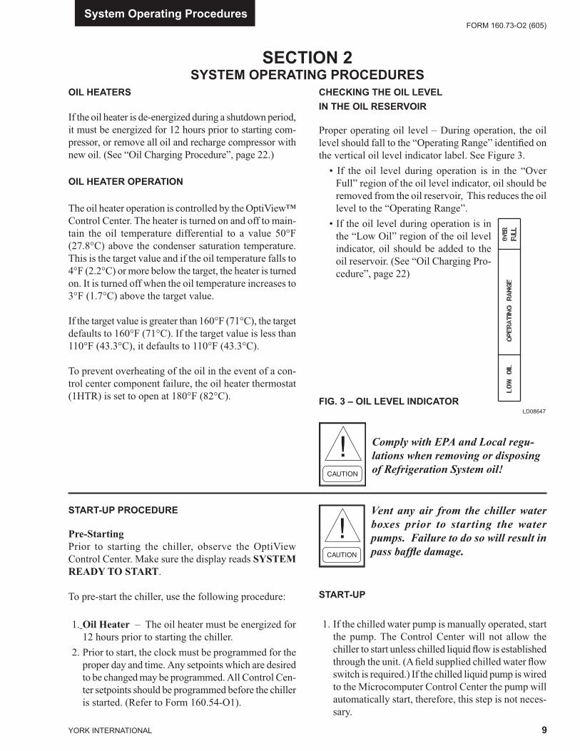
CHECKING THE OIL LEVEL IN THE OIL RESERVOIR
Proper operating oil level – During operation, the oil level should fall to the “Operating Range” identifi ed on the vertical oil level indicator label. See Figure 3. • If the oil level during operation is in the “Over
Full” region of the oil level indicator, oil should be removed from the oil reservoir, This reduces the oil level to the “Operating Range”.
• If the oil level during operation is in the “Low Oil” region of the oil level indicator, oil should be added to the oil reservoir. (See “Oil Charging Pro-cedure”, page 22)
START-UP PROCEDURE
Pre-StartingPrior to starting the chiller, observe the OptiView Control Center. Make sure the display reads SYSTEM READY TO START.
To pre-start the chiller, use the following procedure:
1. Oil Heater – The oil heater must be energized for 12 hours prior to starting the chiller.
2. Prior to start, the clock must be programmed for the proper day and time. Any setpoints which are de sired to be changed may be programmed. All Control Cen-ter setpoints should be pro grammed before the chiller is started. (Refer to Form 160.54-O1).
Vent any air from the chiller water boxes prior to starting the water pumps. Failure to do so will result in pass baffl e damage.
START-UP
1. If the chilled water pump is manually operated, start the pump. The Control Center will not allow the chill er to start unless chilled liquid fl ow is es tab lished through the unit. (A fi eld supplied chilled wa ter fl ow switch is required.) If the chilled liquid pump is wired to the Microcomputer Control Cen ter the pump will au to mat i cal ly start, therefore, this step is not neces-sary.
System Op er at ing Pro ce dures
SECTION 2SYSTEM OPERATING PROCEDURES
OIL HEATERS
If the oil heater is de-energized during a shut down pe ri od, it must be energized for 12 hours prior to start ing com- pres sor, or remove all oil and re charge com pres sor with new oil. (See “Oil Charging Pro ce dure”, page 22.)
OIL HEATER OPERATION
The oil heater operation is controlled by the OptiView™ Control Center. The heater is turned on and off to main-tain the oil temperature differential to a val ue 50°F (27.8°C) above the condenser saturation tem per a ture. This is the target value and if the oil tem per a ture falls to 4°F (2.2°C) or more below the target, the heater is turned on. It is turned off when the oil temperature increases to 3°F (1.7°C) above the target value.
If the target value is greater than 160°F (71°C), the tar get de faults to 160°F (71°C). If the target value is less than 110°F (43.3°C), it defaults to 110°F (43.3°C).
To prevent over heat ing of the oil in the event of a con- trol center component fail ure, the oil heat er ther mo stat (1HTR) is set to open at 180°F (82°C). FIG. 3 – OIL LEVEL INDICATOR
LD08647
Comply with EPA and Local reg u -la tions when re mov ing or disposing of Re frig er a tion System oil!
YORK INTERNATIONAL
FORM 160.73-O2 (605)
10
2. To start the chiller, press the COM PRES SOR START switch. This switch will au to mat i cal ly spring return to the RUN position. (If the unit was pre vi ous ly started, press the STOP/RE SET side of the COMPRESSOR switch and then press the START side of the switch to start the chiller.) When the start switch is energized, the Control Center is placed in an operating mode and any malfunction will be not ed by messages on a graphic display.
Any malfunctions which oc cur dur ing STOP/RE SET are also displayed.
When the chiller is shut down, the prerotation vanes will close au to mat i cal ly to prevent load ing the com pres sor on start-up.
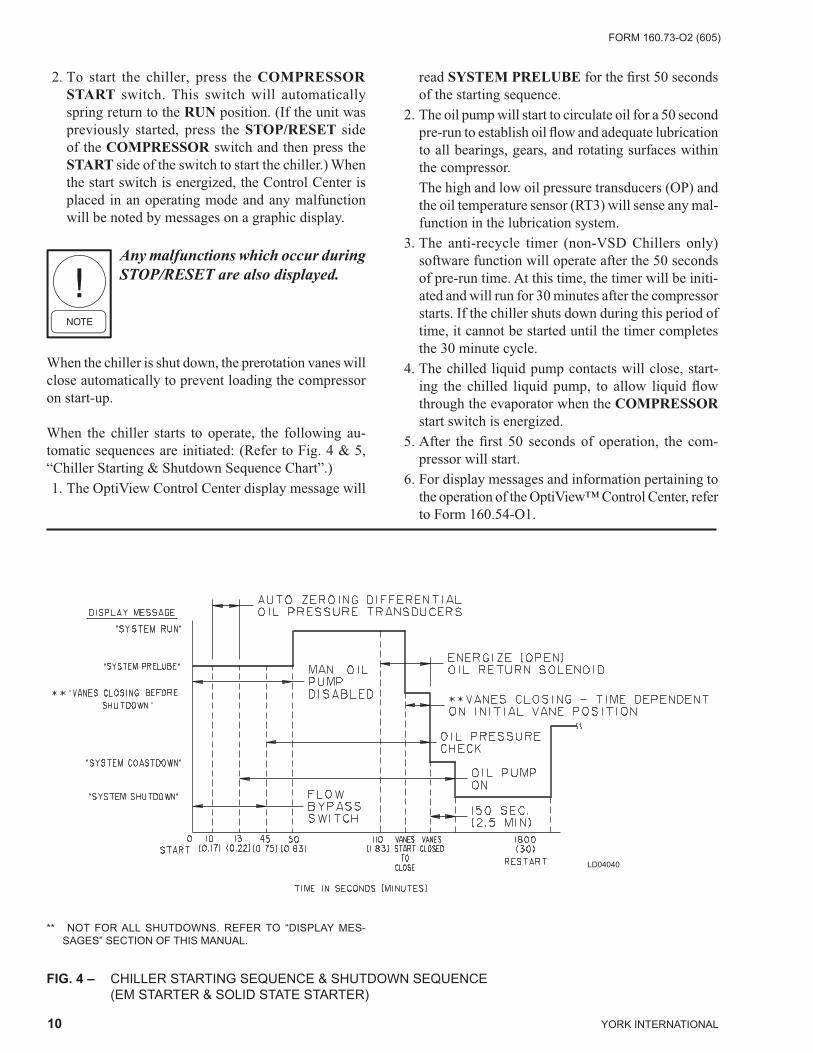
When the chiller starts to op er ate, the fol low ing au- to mat ic sequences are initiated: (Refer to Fig. 4 & 5, “Chill er Start ing & Shutdown Se quence Chart”.) 1. The OptiView Control Center display mes sage will
read SYSTEM PRELUBE for the fi rst 50 sec onds of the start ing sequence.
2. The oil pump will start to circulate oil for a 50 sec ond pre-run to establish oil fl ow and ad e quate lu bri ca tion to all bearings, gears, and rotating sur fac es within the compressor.
The high and low oil pressure transducers (OP) and the oil temperature sensor (RT3) will sense any mal-function in the lubrication system.
3. The anti-recycle timer (non-VSD Chillers only) software function will op er ate af ter the 50 seconds of pre-run time. At this time, the timer will be initi-ated and will run for 30 min utes after the compressor starts. If the chiller shuts down during this period of time, it cannot be started until the timer com pletes the 30 minute cy cle.
4. The chilled liquid pump contacts will close, start- ing the chilled liquid pump, to allow liquid fl ow through the evaporator when the COMPRESSOR start switch is energized.
5. After the fi rst 50 seconds of operation, the com- pres sor will start.
6. For display messages and information per tain ing to the op er a tion of the OptiView™ Con trol Cen ter, re fer to Form 160.54-O1.
FIG. 4 – CHILLER STARTING SEQUENCE & SHUT DOWN SEQUENCE (EM STARTER & SOLID STATE STARTER)
LD04040
** NOT FOR ALL SHUTDOWNS. REFER TO “DISPLAY MES- SAG ES” SECTION OF THIS MANUAL.

FORM 160.73-O2 (605)
11YORK INTERNATIONAL
2
FIG. 5 – CHILLER STARTING SEQUENCE & SHUTDOWN SEQUENCE (VARIABLE SPEED DRIVE)
LD04130
CHILLER OPERATION
After the compressor reaches its operating speed, the Prerotation Vanes will begin to open under the control of the Microprocessor Board which senses the leaving chilled liquid temperature. The unit capacity will vary to maintain the leaving CHILLED LIQUID TEM PER A- TURE setpoint. The Prerotation Vanes are mod u lat ed by an actuator un der the control of the Mi cro pro ces sor Board. The vane control routine employs pro por tion al plus de riv a tive (rate) control action. A drop in chilled liquid tem per a ture will cause the actuator to close the Prerotation Vanes to de crease chiller ca pac i ty. When the chilled liq uid tem per a ture rises, the ac tu a tor will open the Prerotation Vanes to increase the ca pac i ty of the chiller.
However, the current draw (amperes) by the com pres sor motor cannot exceed the setting of the % CUR RENT LIM IT at any time during the unit operation, since the Microcomputer Control Center 40 to 100% three-phase peak current limit software function, plus the 3-phase 100% solid state overload current limiter (CM-2), on Electro-Mechanical Starter applications, or the Solid State Starter current Limit function will over ride the tem per a ture control function and prevent the Pre rota tion Vanes from opening beyond the % CUR RENT LIMIT setting.
** NOT FOR ALL SHUTDOWNS. REFER TO “DISPLAY MES- SAG ES” SECTION OF THIS MANUAL.
System Op er at ing Pro ce dures
If the load continues to decrease, after the Prerotation Vanes are entirely closed, the chiller will be shut down by the Leaving Chilled Liquid – Low Temperature Con trol.
CONDENSER WATER TEMPERATURE CON TROL
The YORK MaxETM chiller is designed to use less power by taking advantage of lower than design tem per a tures that are naturally produced by cooling tow ers through out the operating year. Exact control of con dens er water such as a cooling tower bypass, is not nec es sary for most installations. The chiller requires only that the minimum condenser water temperature be no lower than the value determined by referring to the for mu la below:
where:
ECWT = Entering Condensing Water Temperature LCWT = Leaving Chilled Water TemperatureC Range = Condensing water temperature range at the given load condition.
Min. ECWT = LCWT – C RANGE + 17ºFMin. ECWT = LCWT – C RANGE + 9.4ºC
YORK INTERNATIONAL
FORM 160.73-O2 (605)
12
OPERATING INSPECTIONS – See Section 2
By following a regular inspection using the display read ings of the Microcomputer Control Center, and main te nance procedure, the operator will avoid serious op er at ing diffi culty. The following list of inspections and pro ce dures should be used as a guide.
Daily
1. Check OptiView™ Control Center dis plays. 2. If the compressor is in operation, check the bear ing
oil pressure on the SYSTEM Screen. Also check the oil level in the oil res er voir. Operating oil level should be operating range of oil indicator. Drain or add oil if nec es sary.
3. Check entering and leaving condenser water pres sure and temperatures for comparison with job de sign con di tions. Condenser water tem per a tures can be checked on the SYSTEM Screen.
4. Check the entering and leaving chilled liquid tem- per a tures and evaporator pressure for com par i son with job design conditions on the SYSTEM Screen.
5. Check the condenser saturation temperature (based upon condenser pressure sensed by the con dens er transducer) on the SYSTEM Screen.
6. Check the compressor discharge temperature on the SYSTEM Screen. Dur ing normal op er a tion dis charge temperature should not ex ceed 220°F (104°C).
At start-up, the entering condenser water temperature may be as much as 25°F (14°C) colder than the stand by re turn chilled water temperature. Cooling tower fan cy cling will normally provide adequate control of the en ter ing condenser water temperature on most in stal -la tions.
OPERATING LOG SHEET
A permanent daily record of system operating con di tions (temperatures and pressures) recorded at reg u lar inter-vals throughout each 24 hour operating period should be kept.
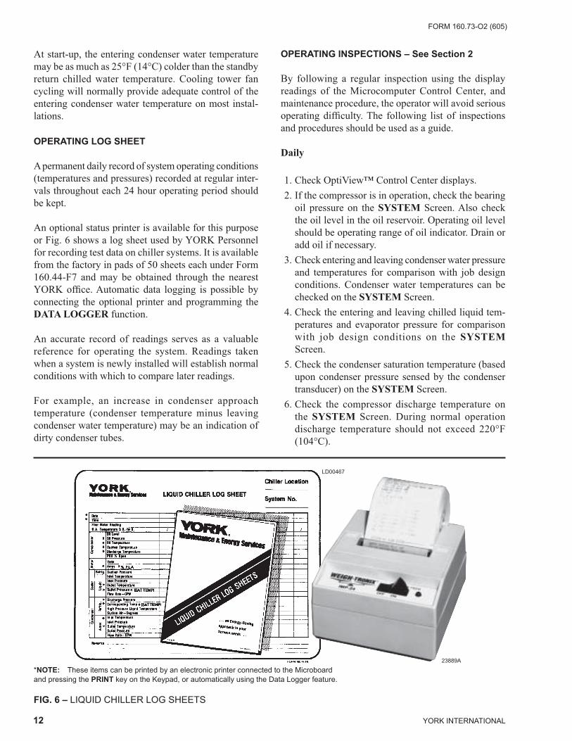
An optional status printer is available for this purpose or Fig. 6 shows a log sheet used by YORK Personnel for recording test data on chiller systems. It is avail able from the factory in pads of 50 sheets each under Form 160.44-F7 and may be obtained through the near est YORK offi ce. Au to mat ic data logging is possible by connecting the optional printer and programming the DATA LOGGER function.
An accurate record of readings serves as a valuable ref er ence for operating the system. Readings taken when a system is newly installed will establish normal con di tions with which to compare later readings.
For example, an increase in condenser approach tem per a ture (condenser temperature minus leaving con dens er water temperature) may be an indication of dirty condenser tubes.
FIG. 6 – LIQUID CHILLER LOG SHEETS
*NOTE: These items can be printed by an electronic printer connected to the Microboard and pressing the PRINT key on the Keypad, or automatically using the Data Logger feature.
LD00467
23889A
FORM 160.73-O2 (605)
13YORK INTERNATIONAL
2
7. Check the compressor motor current on the SYS TEM Screen.
8. Check for any signs of dirty or fouled con dens er tubes. (The temperature difference between water leaving condenser and saturated con dens ing tem- per a ture should not exceed the difference re cord ed for a new unit by more than 4°F, 2.2°C).
Weekly
1. Check the refrigerant charge. (See “Checking The Refrigerant Charge”, page 28.)
Monthly
1. Leak check the entire chiller.
Quarterly
1. Perform chemical analysis of oil.
Semi-Annually (or more often as required)
1. Change and inspect compressor oil fi lter element.
2. Oil return system.
a. Change dehydrator.
b. Check nozzle of eductor for foreign particles.
3. Check controls and safety cutouts.
Annually (more often if necessary)
If quarterly inspection indicates oil is fi ne, replacing the oil is not necessary.
1. Drain and replace the oil in the compressor oil sump. (See “Oil Charging Procedure” page 22.)
2. Evaporator and Condenser.
a. Inspect and clean water strainers.
b. Inspect and clean tubes as required.
c. Inspect end sheets.
3. Compressor Drive Motor (See motor man u fac tur ers maintenance and service instruction supplied with unit)
a. Clean air passages and windings per man u fac -tur ers instructions.
b. Meg motor windings – See Fig. 13 for details.
c. Lubricate per motor manufacturer recommenda-tions.
4. Inspect and service electrical components as nec es sary.
5. Perform refrigerant analysis.
NEED FOR MAINTENANCE OR SERVICE
If the system is malfunctioning in any manner or the unit is stopped by one of the safety controls, consult the “Operation Analysis Chart”, (Table 1), pages 23 and 24 of this instruction. After consulting this chart, if you are unable to make the proper repairs or ad just -ments to start the compressor or the particular trou ble con tin ues to hinder the performance of the unit, please call the near est YORK District Offi ce. Failure to re port con stant trou bles could damage the unit and in crease the cost of repairs.
STOPPING THE SYSTEM
The Optiview™ Control Center can be pro grammed to start and stop automatically (maximum, once each day) whenever desired. Refer to Form 160.54-O1. To stop the chiller, proceed as follows:
1. Push the COMPRESSOR STOP/RESET switch. The compressor will stop au to mat i cal ly. The oil pump will continue to run for coastdown pe ri od. The oil pump will then stop au to mat i cal ly.
2. Stop the chilled water pump (if not wired into the Microcomputer Control Center, in which case it will shut off automatically si mul ta neous ly with the oil pump.) (The actual water pump con tact op er a tion is dependent upon the position of Microboard jump er J54.)
3. Open the switch to the cooling tower fan motors, if used.
4. The compressor sump oil heater is energized when the unit is stopped.
PROLONGED SHUTDOWN
If the chiller is to be shut down for an extended period of time (for example, over the winter season), the fol low ing paragraphs outline the procedure to be fol lowed. 1. Test all system joints for refrigerant leaks with a
System Op er at ing Pro ce dures
YORK INTERNATIONAL
FORM 160.73-O2 (605)
14
leak detector. If any leaks are found, they should be re paired before allowing the system to stand for a long period of time.
During long idle periods, the tightness of the sys tem should be checked periodically.
2. If freezing temperatures are encountered while the system is idle, carefully drain the cooling water from the cooling tower, condenser, con dens er pump, and the chilled water system-chilled water pump and coils.
Open the drains on the evaporator and condenser liquid heads to assure complete drainage. (If a Vari-
able Speed Drive, drain its water cooling system. If Sol id State Starter. drain water from starter cooling loop.)
3. On the SETUP Screen, disable the clock. This con- serves the bat tery.
4. Open the main disconnect switches to the com pres sor motor, condenser water pump and the chilled water pump. Open the 115 volt circuit to the Con trol Cen-ter.
FORM 160.73-O2 (605)
15YORK INTERNATIONAL
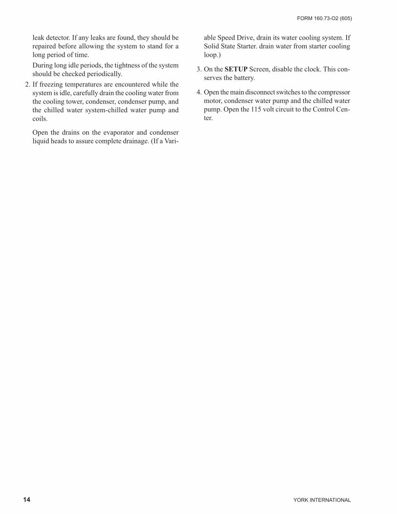
SECTION 3SYSTEM COMPONENTS DE SCRIP TION
MOTOR
EVAPORATOR
COMPRESSOR
SUCTION
DUAL RELIEFVALVES
SIGHTGLASS
VARIABLE SPEED OIL PUMP CON TROL
BOX
REFRIGERANTCHARGING VALVE
00611vip
FRONT VIEW
FIG. 7 – SYSTEM COMPONENTS
OPTIVIEW CON TROLCENTER
3
YORK INTERNATIONAL
FORM 160.73-O2 (605)
16
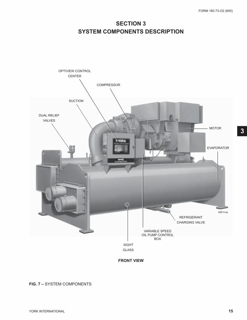
FIG. 7 – SYSTEM COMPONENTS (CONT’D)
28778A
DISCHARGE LINE
OIL COOLER
OIL RESERVOIR PUMP
REAR VIEW
System Components De scrip tion

FORM 160.73-O2 (605)
17YORK INTERNATIONAL
GENERAL
The YORK Model YK MaxETM Centrifugal Liquid Chill er is completely factory-packaged including evapo-rator, condenser, compressor, motor, lubrication system, OptiView Control Center, and all in ter con nect ing unit piping and wiring.
COMPRESSOR
The compressor is a single-stage centrifugal type pow- ered by an open-drive electric motor.
The rotor assembly consists of a heat-treated alloy steel drive shaft and impeller shaft with a cast alu mi num, ful ly shrouded impeller. The impeller is designed for bal- anced thrust and is dynamically balanced and over-speed tested. The inserted type journal and thrust bear ings are fab ri cat ed of aluminum alloy. Single helical gears with crowned teeth are designed so that more than one tooth is in contact at all times. Gears are integrally as sem bled in the compressor rotor support and are fi lm lu bri cat ed. Each gear is individually mounted in its own journal and thrust bearings.
The open-drive compressor shaft seal is a double bellows cartridge style with ceramic internal and atmospheric seal faces. The seal is oil-fl ooded at all times and is pressure-lubricated during operation.
CAPACITY CONTROL
Prerotation vanes (PRV) modulate chiller capac-ity from 100% to as low as 15% of design for normal air con di tion ing applications. Operation is by an external, elec tric PRV actuator which automatically controls the vane position to main-tain a constant leaving chilled liquid tem per a ture.
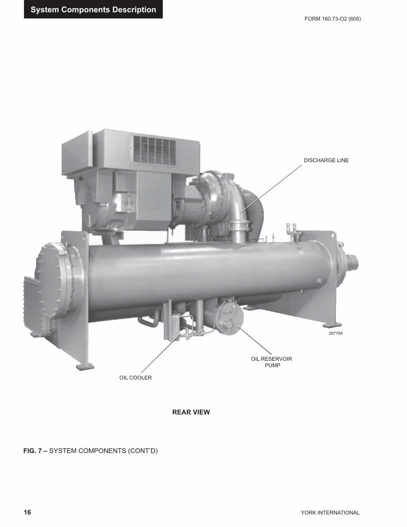
COMPRESSOR LUBRICATION SYSTEM (See Fig. 8)
The chiller lubrication system consists of the oil pump, oil fi l ter, oil cooler and all interconnecting oil piping and pas sag es. There are main points within the motor-com pres sor which must be supplied with forced lu bri -ca tion as follows:
1. Compressor Drive Shaft (Low Speed) a. Shaft seal. b. Front and rear journal bear ings – one on each
side of driving gear. c. Low speed thrust bearing (for ward and re verse). 2. Compressor Driven Shaft (High Speed) a. Forward and reverse high speed thrust
bearing. b. Two journal bearings. 3. Speed Increasing Gears a. Meshing surfaces of drive and pinion gear teeth.
To provide the required amount of oil under the nec- es sary pressure to properly lubricate these parts, a mo tor driven submersible oil pump is located in a remote oil sump.
Upon pressing of the COMPRESSOR START switch on the Control Center, the oil pump is immediately en er gized. After a 50 second pre-lube period, the com- pres sor mo tor will start. The oil pump will continue to run dur ing the entire op er a tion of the compressor, and for 150 sec onds dur ing compressor coastdown.
The submerged oil pump takes suction from the sur- round ing oil and discharges it to the oil cooler where heat is rejected. The oil fl ows from the oil cooler to the oil fi lter. The oil leaves the fi lter and fl ows to the emer gen cy oil reservoir where it is distributed to the com pres sor bearings. The oil lubricates the compressor ro tat ing components and is returned to the oil sump.
There is an emergency oil reservoir located at the high est point in the lubrication system internally in the com pres sor. It pro vides an oil sup ply to the var i ous bear ings and gears in the event of a sys tem shut down due to power fail ure. The res er voir, lo cat ed on the top of the com pres sor, allows the oil to be dis trib ut ed through the pas sag es by grav i ty fl ow, thus pro vid ing necessary lu bri ca tion during the com pres sor coastdown.
3
YORK INTERNATIONAL
FORM 160.73-O2 (605)
18
LOW SPEEDGEAR REARBEARING
DOUBLE BELLOWS SHAFT SEAL
FIG. 8 – SCHEMATIC DRAWING – (YK) COM PRES SOR LUBRICATION SYSTEM LD08577
System Components De scrip tion
FORM 160.73-O2 (605)
19YORK INTERNATIONAL
OIL PUMP
For normal operation, the oil pump should operate at all times during chiller operation.
On shutdown of the system for any reason, the oil pump operates and continues to run for 150 seconds. The sys- tem cannot restart during that time interval.
OIL HEATER
During long idle periods, the oil in the compressor oil reservoir tends to absorb as much refrigerant as it can hold, depending upon the temperature of the oil and the pressure in the reservoir. As the oil temperature is low ered, the amount of refrigerant absorbed will be in creased. If the quantity of refrigerant in the oil be- comes excessive, violent oil foaming will result as the pres sure within the system is lowered on starting. This foam ing is caused by refrigerant boiling out of the oil as the pres sure is lowered. If this foam reaches the oil pump suc tion, the bearing oil pressure will fl uctuate with pos si ble temporary loss of lubrication, causing the oil pres sure safety cutout to actuate and stop the system. See “Con trol Center” Form 160.54-O1.
MOTOR DRIVELINE
The compressor motor is an open-drip-proof, squirrel cage, induction type constructed to YORK design spec- i fi ca tions. 60 hertz motors operate at 3570 rpm. 50 hertz motors operate at 2975 rpm.
The open motor is provided with a D-fl ange, cast iron adapter mounted to the compressor and supported by a motor support.
Motor drive shaft is directly connected to the com pres sor shaft with a fl exible disc coupling. This coupling has all metal construction with no wearing parts to as sure long life, and no lubrication requirements to pro vide low maintenance.
For units utilizing remote Electro-Mechanical starters, a terminal box is provided for fi eld connected conduit. Motor terminals are brought through the motor casing into the terminal box. Jumpers are furnished for three-lead type of starting. Motor terminal lugs are not fur- nished. Overload/overcurrent transformers are fur nished with all units.
HEAT EXCHANGERS
Evaporator and condenser shells are fabricated from rolled carbon steel plates with fusion welded seams.
Heat exchanger tubes are internally enhanced type.
The evaporator is a shell and tube, fl ooded type heat exchanger. A distributor trough provides uniform dis tri bu tion of refrigerant over the entire shell length. Stain less steel mesh elim i na tors or suction baffl es are lo cat ed above the tube bun dle to pre vent liquid re frig -er ant carryover into the com pres sor. A 2" liquid level sight glass is lo cat ed on the side of the shell to aid in de ter min ing proper re frig er ant charge. The evap o ra tor shell con tains dual re frig er ant relief valves.
The condenser is a shell and tube type, with a dis charge gas baffl e to prevent direct high velocity im pinge ment on the tubes. A separate subcooler is lo cat ed in the con- dens er to enhance performance. Dual refrigerant relief valves are located on condenser shells with op tion al iso la tion refrigerant isolation valves.
The removable compact water boxes are fabricated of steel. The design working pressure is 150 PSIG (1034 kPa) and the boxes are tested at 225 PSIG (1551 kPa). In te gral steel wa ter baf fl es provide the required pass ar range ments. Stub-out wa ter nozzle connections with Victaulic grooves are weld ed to the water boxes. These nozzle connections are suitable for Victaulic cou plings, weld ing or fl anges, and are capped for shipment. Plugged 3/4" drain and vent connections are provided in each water box.
REFRIGERANT FLOW CONTROL Refrigerant fl ow to the evaporator is controlled by a variable orifi ce.
A level sensor senses the re frig er ant level in the con- dens er and outputs an analog volt age to the Microboard that represents this level (0% = empty; 100% = full). Under program control, the Microboard mod u lates a variable orifi ce to control the con dens er re frig er ant lev el to a programmed setpoint. Oth er setpoints affect the control sensitivity and re sponse. These set points must be entered at chiller com mis sion ing by a qualifi ed ser- vice technician. Only a qual i fi ed service technician may modify these settings.
3

YORK INTERNATIONAL
FORM 160.73-O2 (605)
20
While the chiller is shut down, the orifi ce will be in the fully open position causing the sensed level to be ap- prox i mate ly 0%. When the chiller is started, after the vane motor end switch (VMS) opens when entering SYSTEM RUN, if actual level is less than the level setpoint, a linearly increasing ramp is applied to the lev el setpoint. This ramp causes the setpoint to go from the initial refrigerant level (approximately 0%) to the pro grammed setpoint over a period of 15 minutes.
If the actual level is greater than the setpoint when the VMS opens, there is no pulldown period, it im me di ate ly begins to control to the programmed setpoint.
While the chiller is running, the refrigerant level is nor- mal ly controlled to the level setpoint. However, any time the vanes fully close (VMS closes), normal level con trol is terminated, any refrigerant level setpoint pulldown in effect is cancelled and the outputs to the level control will be opposite that which is supplied to the vane motor (i.e., when a close pulse is applied to the vane motor, an open pulse is applied to the level control, etc.). When the VMS opens, if the refrigerant level is less than the level set point, a refrigerant level setpoint pulldown is initiated as described above. Oth er wise, the level is con trolled to the programmed set point.
OPTIONAL SERVICE ISOLATION VALVES
If your chiller is equipped with optional service iso la tion valves on the discharge and liquid line, these valves must remain open during operation. These valves are used for isolating the refrigerant charge in either the evap o ra tor or condenser to allow service access to the sys tem. A re frig er ant pump-out unit will be required to iso late the re frig er ant.
Isolation of the refrigerant in this sys- tem must be per formed by a qualifi ed service tech ni cian.
OPTIONAL HOT GAS BYPASSHot gas bypass is optional and is used to eliminate com pres sor surge during light load or high head op- er a tion. The OptiView con trol panel will automatically mod u late the hot gas valve open and closed as re quired. Ad just ment of the hot gas control valve must be per- formed by a qual i fi ed service tech ni cian fol low ing the Hot Gas Set-up pro ce dure.
Changes in chilled water flow will re quire re ad just ment of the hot gas con trol to in sure prop er operation.
OTIVIEW CONTROL CENTER(See Section 2)
The OptiView Control Center is factory-mounted, wired and tested. The elec tron ic panel automatically controls the op er a tion of the unit in meet ing system cool ing re- quire ments while minimizing en er gy usage. For de tailed in for ma tion on the Control Center, refer to “Sec tion 2” of this manual.
SOLID STATE STARTER (Optional)
The Solid State Starter is a reduced voltage starter that controls and maintains a constant current fl ow to the motor during start-up. It is mounted on the chiller. Pow er and control wiring between the starter and chill er are factory installed. Available for 380-600 volts, the start er enclosure is NEMA-1 with a hinged access door with lock and key. Electrical lugs for incoming power wir ing are provided.
VARIABLE SPEED DRIVE (Optional)
A 460V – 3-Ph – 60/50 Hz Variable Speed Drive can be factory packaged with the chiller. It is designed to vary the compressor motor speed and prerotation vane po si tion by controlling the frequency and voltage of the elec tri cal power to the motor. Operational informa-tion is contained in Form 160.00-O1. The control logic au to mat i cal ly adjusts motor speed and compressor pre-rotation vane position for maximum part load ef fi cien cy by an a lyz ing information fed to it by sensors located through out the chiller.
System Components De scrip tion
FORM 160.73-O2 (605)
21YORK INTERNATIONAL
OIL EDUCTOR BLOCK
SOLENOID VALVE
SOLENOID VALVE
DEHYDRATOR
STOP VALVE
STOP VALVE
CHECK VALVE
COMPRESSOR
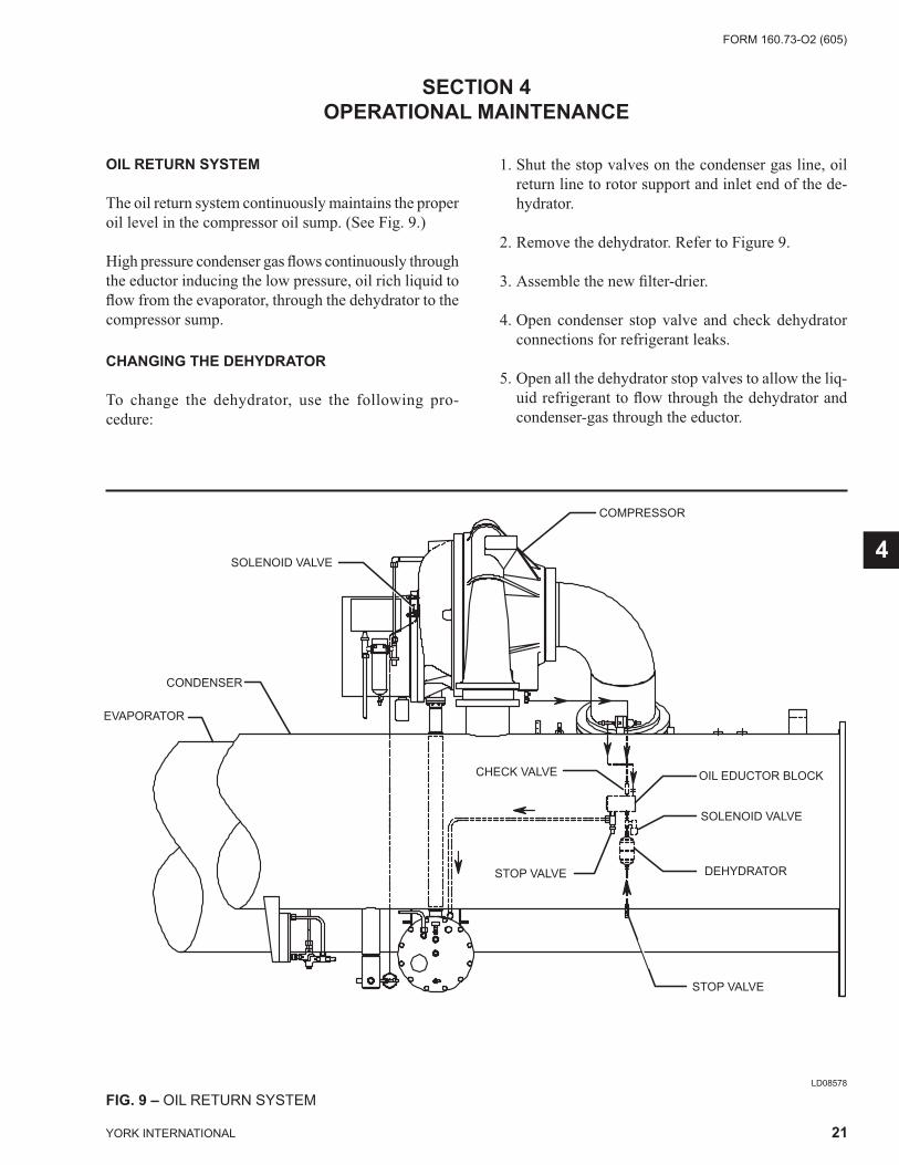
FIG. 9 – OIL RETURN SYSTEMLD08578
SECTION 4OPERATIONAL MAINTENANCE
OIL RETURN SYSTEM
The oil return system continuously maintains the prop er oil level in the compressor oil sump. (See Fig. 9.)
High pressure condenser gas fl ows continuously through the eductor inducing the low pressure, oil rich liquid to fl ow from the evaporator, through the de hy dra tor to the compressor sump.
CHANGING THE DEHYDRATOR
To change the dehydrator, use the following pro- ce dure:
1. Shut the stop valves on the condenser gas line, oil return line to rotor support and inlet end of the de- hy dra tor.
2. Remove the dehydrator. Refer to Figure 9.
3. Assemble the new fi lter-drier.
4. Open condenser stop valve and check dehydrator connections for refrigerant leaks.
5. Open all the dehydrator stop valves to allow the liq- uid re frig er ant to fl ow through the dehydrator and con dens er-gas through the eductor.
4
YORK INTERNATIONAL
FORM 160.73-O2 (605)
22
THE OIL CHARGE
The nominal oil charge for all H, J, & P6-P9 YK com-pressors is 20 gallons, and for P1-P5 & Q7 YK compres-sors is 10 gallons of type “York K”.
New YORK Refrigeration oil must be used in the cen- trif u gal compressor. Since oil absorbs moisture when exposed to the atmosphere, it should be kept tightly capped until used.
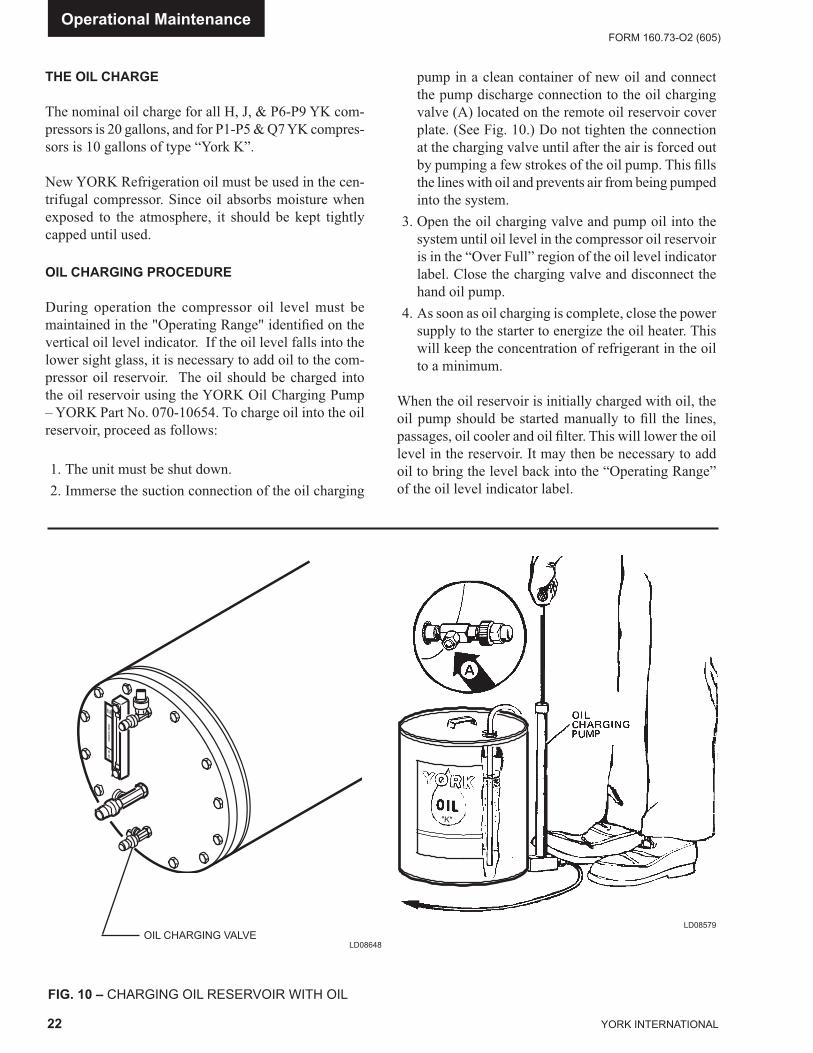
OIL CHARGING PROCEDURE
During operation the compressor oil level must be maintained in the "Operating Range" identifi ed on the vertical oil level indicator. If the oil level falls into the lower sight glass, it is necessary to add oil to the com-pressor oil reservoir. The oil should be charged into the oil reservoir using the YORK Oil Charg ing Pump – YORK Part No. 070-10654. To charge oil into the oil reservoir, proceed as follows:
1. The unit must be shut down. 2. Immerse the suction connection of the oil charging
pump in a clean container of new oil and connect the pump discharge connection to the oil charging valve (A) located on the remote oil reservoir cover plate. (See Fig. 10.) Do not tighten the connection at the charging valve until after the air is forced out by pumping a few strokes of the oil pump. This fi lls the lines with oil and prevents air from being pumped into the system.
3. Open the oil charging valve and pump oil into the system until oil level in the compressor oil res er voir is in the “Over Full” region of the oil level indicator label. Close the charging valve and disconnect the hand oil pump.
4. As soon as oil charging is complete, close the pow er supply to the starter to energize the oil heater. This will keep the concentration of refrigerant in the oil to a minimum.
When the oil reservoir is initially charged with oil, the oil pump should be started manually to fi ll the lines, pas sag es, oil cooler and oil fi lter. This will lower the oil level in the reservoir. It may then be necessary to add oil to bring the level back into the “Operating Range” of the oil level indicator label.
FIG. 10 – CHARGING OIL RESERVOIR WITH OIL
LD08579
Operational Maintenance
LD08648OIL CHARG ING VALVE
FORM 160.73-O2 (605)
23YORK INTERNATIONAL
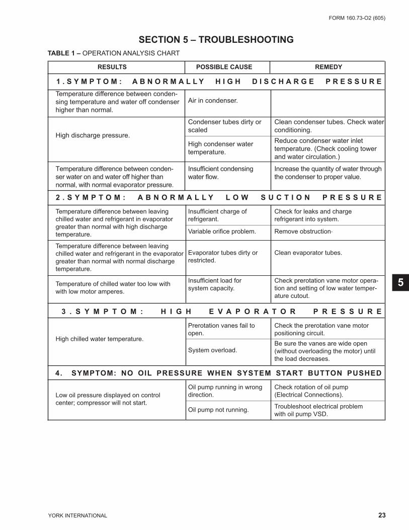
RESULTS POSSIBLE CAUSE REMEDY
1 . S Y M P T O M : A B N O R M A L L Y H I G H D I S C H A R G E P R E S S U R E Temperature difference between conden-
Air in condenser. sing temperature and water off condenser higher than normal.
High discharge pressure.
Condenser tubes dirty or Clean condenser tubes. Check water scaled conditioning. High condenser water Reduce condenser water inlet temperature. temperature. (Check cooling tower and water circulation.)
Temperature difference between conden- Insuffi cient condensing Increase the quantity of water through ser water on and water off higher than water fl ow. the condenser to proper value. normal, with normal evaporator pressure.
2 . S Y M P T O M : A B N O R M A L L Y L O W S U C T I O N P R E S S U R E
Temperature difference between leaving Insuffi cient charge of Check for leaks and charge chilled water and refrigerant in evaporator refrigerant. refrigerant into system. greater than normal with high discharge
Variable orifi ce problem. Remove obstruction. temperature.
Temperature difference between leaving Evaporator tubes dirty or
Clean evaporator tubes. chilled water and refrigerant in the evaporator
restricted. greater than normal with normal discharge temperature.
Temperature of chilled water too low with Insuffi cient load for Check prerotation vane motor opera-
with low motor amperes. system capacity. tion and setting of low water temper- ature cutout.
3 . S Y M P T O M : H I G H E V A P O R A T O R P R E S S U R E
High chilled water temperature.
Prerotation vanes fail to Check the prerotation vane motor open. positioning circuit.
System overload. Be sure the vanes are wide open
(without overloading the motor) until the load decreases.
4. SYMPTOM: NO OIL PRESSURE WHEN SYSTEM START BUTTON PUSHED
Low oil pressure displayed on control
Oil pump running in wrong Check rotation of oil pump
center; compressor will not start. direction. (Electrical Connections).
Oil pump not running. Troubleshoot electrical problem with oil pump VSD.
TABLE 1 – OPERATION ANALYSIS CHART
SECTION 5 – TROUBLESHOOTING
5
YORK INTERNATIONAL
FORM 160.73-O2 (605)
24
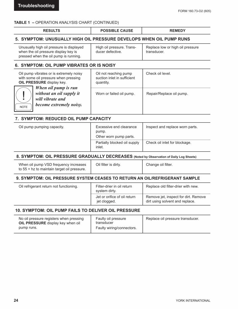
TABLE 1 – OPERATION ANALYSIS CHART (CONTINUED)
RESULTS POSSIBLE CAUSE REMEDY
5. SYMPTOM: UNUSUALLY HIGH OIL PRESSURE DEVELOPS WHEN OIL PUMP RUNS
Unusually high oil pressure is displayed High oil pressure. Trans- Replace low or high oil pressure when the oil pressure display key is ducer defective. transducer. pressed when the oil pump is running.
6. SYMPTOM: OIL PUMP VIBRATES OR IS NOISY
Oil pump vibrates or is extremely noisy Oil not reaching pump Check oil level. with some oil pressure when pressing suction inlet in suffi cient OIL PRESSURE display key. quan ti ty.
When oil pump is run without an oil supply it Worn or failed oil pump. Repair/Replace oil pump.will vibrate and become extremely noisy.
7. SYMPTOM: REDUCED OIL PUMP CAPACITY
Oil pump pumping capacity. Excessive end clearance Inspect and replace worn parts. pump. Other worn pump parts. Partially blocked oil supply Check oil inlet for blockage. inlet. 8. SYMPTOM: OIL PRESSURE GRADUALLY DECREASES (Noted by Observation of Daily Log Sheets)
When oil pump VSD frequency increases Oil fi lter is dirty. Change oil fi lter. to 55 + hz to maintain target oil pressure.
9. SYMPTOM: OIL PRESSURE SYSTEM CEASES TO RETURN AN OIL/REFRIGERANT SAMPLE
Oil refrigerant return not functioning. Filter-drier in oil return Replace old fi lter-drier with new. system dirty. Jet or orifi ce of oil return Remove jet, inspect for dirt. Remove jet clogged. dirt using solvent and replace. 10. SYMPTOM: OIL PUMP FAILS TO DELIVER OIL PRESSURE
No oil pressure registers when pressing Faulty oil pressure Replace oil pressure transducer. OIL PRESSURE display key when oil transducer pump runs. Faulty wiring/connectors.
Troubleshooting

FORM 160.73-O2 (605)
25YORK INTERNATIONAL
SECTION 6MAINTENANCE
RENEWAL PARTS
For any required Renewal Parts, refer to YORK Re new al Parts Unit Components Manual 160.73-RP1.
CHECKING SYSTEM FOR LEAKS
Leak Testing During OperationThe refrigerant side of the system is carefully pres sure tested and evacuated at the factory.
After the system has been charged, the system should be carefully leak tested with a R-134a compatible leak detector to be sure all joints are tight.
If any leaks are indicated, they must be repaired im- me di ate ly. Usually, leaks can be stopped by tightening fl are nuts or fl ange bolts. However, for any major re pair, the re frig er ant charge must be removed. (See “Han dling Re frig er ant for Dismantling and Repair”, page 29.)
CONDUCTING R-22 PRESSURE TEST
With the R-134a charge removed and all known leaks re paired, the system should be charged with a small amount of R-22 mixed with dry nitrogen so that a ha lide torch or electronic leak detector can be used to detect any leaks too small to be found by the soap test.
To test with R-22, proceed as follows:
1. With no pressure in the system, charge R-22 gas into the system through the charging valve to a pres sure of 2 PSIG (14 kPa).
2. Build up the system pressure with dry nitrogen to ap-proximately 75 to 100 PSIG (517 to 690 kPa). To be sure that the con cen tra tion of refrigerant has reached all part of the sys tem, slightly open the oil charging valve and test for the presence of re frig er ant with a leak de tec tor.
3. Test around each joint and factory weld. It is im por -tant that this test be thoroughly and carefully done, spending as much time as necessary and using a good leak detector.
4. To check for refrigerant leaks in the evaporator and con dens er, open the vents in the evaporator and con- dens er heads and test for the presence of refrigerant. If no refrigerant is present, the tubes and tube sheets may be considered tight. If refrigerant is detected at the vents, the heads must be removed, the leak located (by means of soap test or leak detector) and re paired.
EVACUATION AND DEHYDRATION OF UNIT
FIG. 11 – EVACUATION OF CHILLER
27385A(D)
LD00949
6
YORK INTERNATIONAL
FORM 160.73-O2 (605)
26
VACUUM TESTING
After the pressure test has been completed, the vac u um test should be conducted as follows:
1. Connect a high capacity vacuum pump, with in di -ca tor, to the system charging valve as shown in Fig. 11 and start the pump. (See “Vacuum De hy -dra tion”.)
2. Open wide all system valves. Be sure all valves to the at mo sphere are closed.
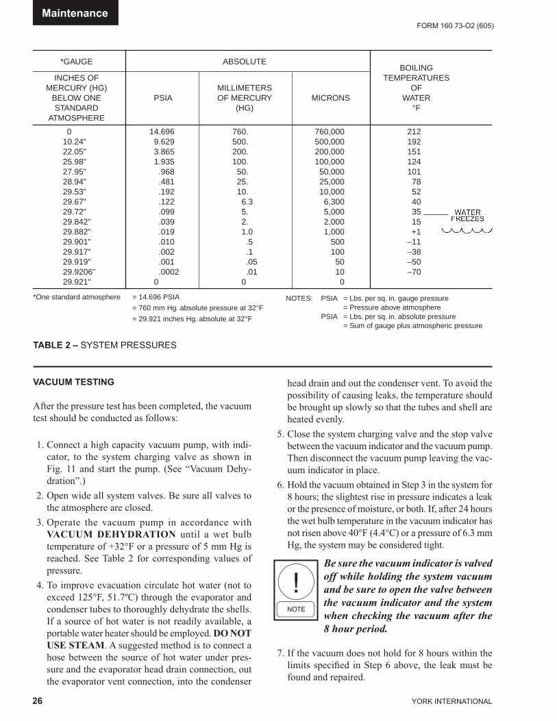
3. Operate the vacuum pump in accordance with VAC U UM DEHYDRATION until a wet bulb tem per a ture of +32°F or a pressure of 5 mm Hg is reached. See Table 2 for corresponding values of pres sure.
4. To improve evacuation circulate hot water (not to exceed 125°F, 51.7ºC) through the evaporator and condenser tubes to thoroughly dehydrate the shells. If a source of hot water is not readily available, a portable wa ter heater should be employed. DO NOT USE STEAM. A suggested method is to connect a hose between the source of hot water under pres-sure and the evaporator head drain connection, out the evaporator vent connection, into the condenser
head drain and out the condenser vent. To avoid the possibility of caus ing leaks, the temperature should be brought up slow ly so that the tubes and shell are heated evenly.
5. Close the system charging valve and the stop valve between the vacuum indicator and the vacuum pump. Then disconnect the vacuum pump leaving the vac- u um indicator in place.
6. Hold the vacuum obtained in Step 3 in the system for 8 hours; the slightest rise in pressure indicates a leak or the presence of moisture, or both. If, after 24 hours the wet bulb temperature in the vacuum in di ca tor has not risen above 40°F (4.4°C) or a pres sure of 6.3 mm Hg, the system may be considered tight.
Be sure the vacuum indicator is valved off while holding the system vacuum and be sure to open the valve between the vac u um indicator and the system when checking the vacuum after the 8 hour period.
7. If the vacuum does not hold for 8 hours within the limits specifi ed in Step 6 above, the leak must be found and repaired.
TABLE 2 – SYSTEM PRESSURES
*GAUGE ABSOLUTE BOILING INCHES OF TEMPERATURES MERCURY (HG) MILLIMETERS OF BELOW ONE PSIA OF MERCURY MICRONS WATER STANDARD (HG) °F ATMOSPHERE
0 14.696 760. 760,000 212 10.24" 9.629 500. 500,000 192 22.05" 3.865 200. 200,000 151 25.98" 1.935 100. 100,000 124 27.95" .968 50. 50,000 101 28.94" .481 25. 25,000 78 29.53" .192 10. 10,000 52 29.67" .122 6.3 6,300 40 29.72" .099 5. 5,000 35 29.842" .039 2. 2,000 15 29.882" .019 1.0 1,000 +1 29.901" .010 .5 500 –11 29.917" .002 .1 100 –38 29.919" .001 .05 50 –50 29.9206" .0002 .01 10 –70 29.921" 0 0 0 *One standard atmosphere = 14.696 PSIA
= 760 mm Hg. absolute pressure at 32°F
= 29.921 inches Hg. absolute at 32°F
NOTES: PSIA = Lbs. per sq. in. gauge pressure = Pressure above atmosphere PSIA = Lbs. per sq. in. absolute pressure = Sum of gauge plus atmospheric pressure
Maintenance
FORM 160.73-O2 (605)
27YORK INTERNATIONAL
VACUUM DEHYDRATION
To obtain a suffi ciently dry system, the following in struc -tions have been assembled to provide an ef fec tive meth od for evacuating and dehydrating a system in the fi eld. Al-though there are several methods of de hy drat ing a sys tem, we are recommending the fol low ing, as it produces one of the best results, and af fords a means of obtaining accurate readings as to the ex tent of de hy dra tion.
The equipment required to follow this method of de- hy dra tion consists of a wet bulb indicator or vacuum gauge, a chart showing the relation between dew point tem per a ture and pressure in inches of mercury (vac u um), (See Table 2) and a vacuum pump capable of pumping a suit able vacuum on the system.
OPERATION
Dehydration of a refrigerant system can be obtained by this method because the water present in the sys tem reacts much as a refrigerant would. By pulling down the pressure in the system to a point where its sat u -ra tion temperature is considerably below that of room tem per a ture, heat will fl ow from the room through the walls of the system and vaporize the water, allowing a large percentage of it to be removed by the vacuum pump. The length of time necessary for the de hy dra tion of a system is dependent on the size or volume of the sys tem, the capacity and effi ciency of the vacuum pump, the room temperature and the quantity of water present in the system. By the use of the vacuum in di ca tor as suggested, the test tube will be evacuated to the same pressure as the system, and the distilled water will be maintained at the same saturation tem per a ture as any free water in the system, and this tem per a ture can be observed on the thermometer.
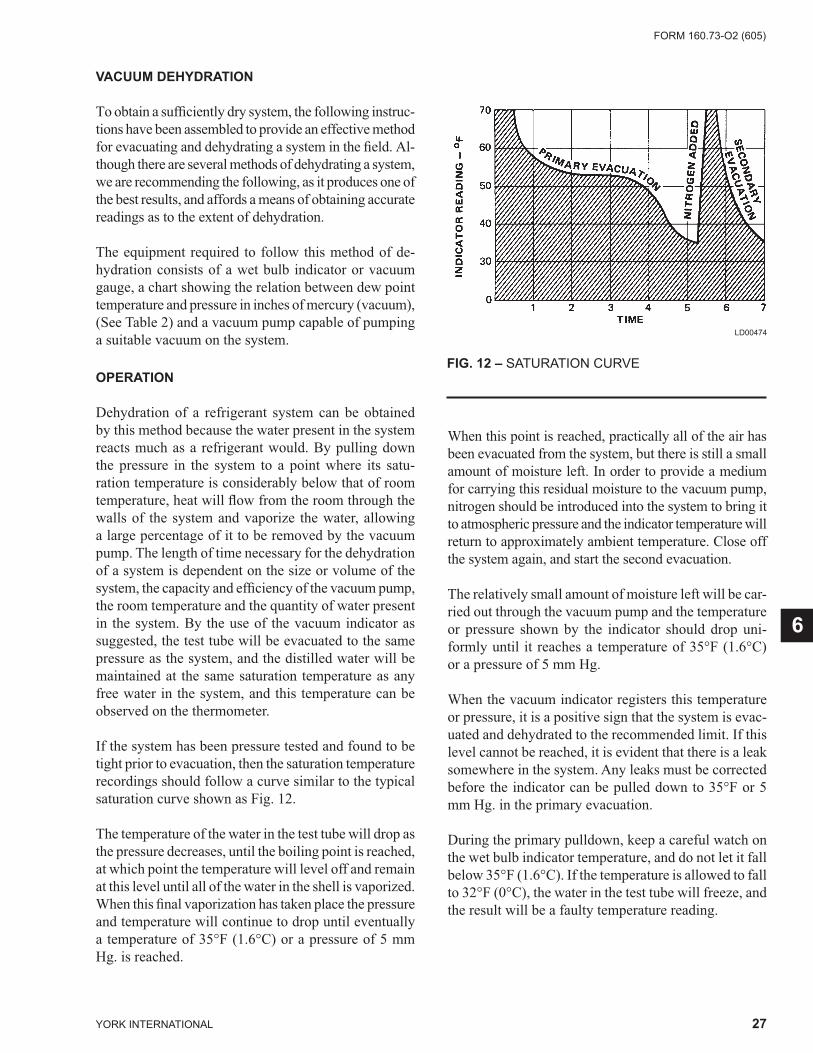
If the system has been pressure tested and found to be tight prior to evacuation, then the saturation tem per a ture recordings should follow a curve similar to the typ i cal saturation curve shown as Fig. 12.
The temperature of the water in the test tube will drop as the pressure decreases, until the boiling point is reached, at which point the temperature will level off and remain at this level until all of the water in the shell is vaporized. When this fi nal vaporization has taken place the pressure and temperature will continue to drop until eventually a temperature of 35°F (1.6°C) or a pres sure of 5 mm Hg. is reached.
When this point is reached, practically all of the air has been evacuated from the system, but there is still a small amount of moisture left. In order to provide a medium for carrying this residual moisture to the vac u um pump, nitrogen should be introduced into the system to bring it to atmospheric pressure and the in di ca tor tem per a ture will return to approximately am bi ent temperature. Close off the system again, and start the second evac u a tion.
The relatively small amount of moisture left will be car- ried out through the vacuum pump and the tem per a ture or pressure shown by the indicator should drop uni- form ly until it reaches a temperature of 35°F (1.6°C) or a pres sure of 5 mm Hg.
When the vacuum indicator registers this temperature or pressure, it is a positive sign that the system is evac- u at ed and dehydrated to the recommended limit. If this level cannot be reached, it is evident that there is a leak somewhere in the system. Any leaks must be cor rect ed before the indicator can be pulled down to 35°F or 5 mm Hg. in the primary evacuation.
During the primary pulldown, keep a careful watch on the wet bulb indicator temperature, and do not let it fall below 35°F (1.6°C). If the temperature is allowed to fall to 32°F (0°C), the water in the test tube will freeze, and the re sult will be a faulty temperature reading.
FIG. 12 – SATURATION CURVE
LD00474
6
YORK INTERNATIONAL
FORM 160.73-O2 (605)
28
REFRIGERANT CHARGINGTo avoid the possibility of freezing liquid within the evaporator tubes when charging an evacuated sys tem, only re frig er ant vapor from the top of the drum or cyl-inder must be admitted to the system pressure until the system pressure is raised above the point cor re spond ing to the freez ing point of the evaporator liq uid. For wa ter, the pres sure cor re spond ing to the freez ing point is 8.54 PSIG (58.9 kPa) for R-134a (at sea level).
While charging, every precaution must be tak en to pre vent moisture laden air from entering the sys tem. Make up a suitable charging con nec tion from new copper tubing to fi t between the system charg ing valve and the fi tting on the charg ing drum. This connection should be as short as possible but long enough to permit suf fi cient fl exibility for changing drums. The charg ing con nec tion should be purged each time a full container of refrigerant is con- nect ed and changing containers should be done as quickly as possible to minimize the loss of re frig er ant.
Refrigerant may be furnished in cylinders con tain ing either 30, 50, 125 or 1750 lbs. (207, 345, 862, or 12,066 kg) of re frig er ant.
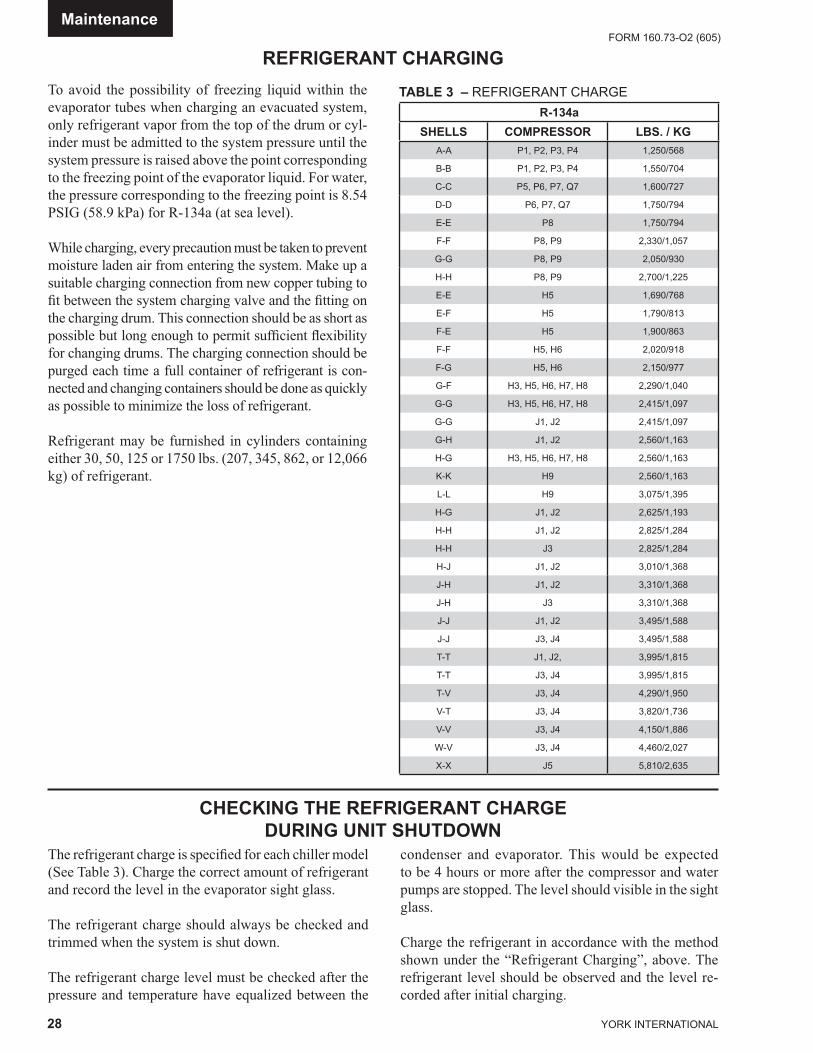
TABLE 3 – REFRIGERANT CHARGE
CHECKING THE REFRIGERANT CHARGEDURING UNIT SHUTDOWN
The refrigerant charge is specifi ed for each chill er mod el (See Table 3). Charge the correct amount of refrigerant and record the level in the evaporator sight glass.
The refrigerant charge should always be checked and trimmed when the system is shut down.
The refrigerant charge level must be checked af ter the pressure and temperature have equalized between the
condenser and evaporator. This would be expected to be 4 hours or more after the com pres sor and water pumps are stopped. The level should visible in the sight glass.
Charge the refrigerant in accordance with the method shown under the “Refrigerant Charging”, above. The refrigerant lev el should be observed and the level re- cord ed after initial charg ing.
Maintenance
R-134aSHELLS COMPRESSOR LBS. / KG
A-A P1, P2, P3, P4 1,250/568
B-B P1, P2, P3, P4 1,550/704
C-C P5, P6, P7, Q7 1,600/727
D-D P6, P7, Q7 1,750/794
E-E P8 1,750/794
F-F P8, P9 2,330/1,057
G-G P8, P9 2,050/930
H-H P8, P9 2,700/1,225
E-E H5 1,690/768
E-F H5 1,790/813
F-E H5 1,900/863
F-F H5, H6 2,020/918
F-G H5, H6 2,150/977
G-F H3, H5, H6, H7, H8 2,290/1,040
G-G H3, H5, H6, H7, H8 2,415/1,097
G-G J1, J2 2,415/1,097
G-H J1, J2 2,560/1,163
H-G H3, H5, H6, H7, H8 2,560/1,163
K-K H9 2,560/1,163
L-L H9 3,075/1,395
H-G J1, J2 2,625/1,193
H-H J1, J2 2,825/1,284
H-H J3 2,825/1,284
H-J J1, J2 3,010/1,368
J-H J1, J2 3,310/1,368
J-H J3 3,310/1,368
J-J J1, J2 3,495/1,588
J-J J3, J4 3,495/1,588
T-T J1, J2, 3,995/1,815
T-T J3, J4 3,995/1,815
T-V J3, J4 4,290/1,950
V-T J3, J4 3,820/1,736
V-V J3, J4 4,150/1,886
W-V J3, J4 4,460/2,027
X-X J5 5,810/2,635
FORM 160.73-O2 (605)
29YORK INTERNATIONAL
HANDLING REFRIGERANT FORDISMANTLING AND REPAIRS
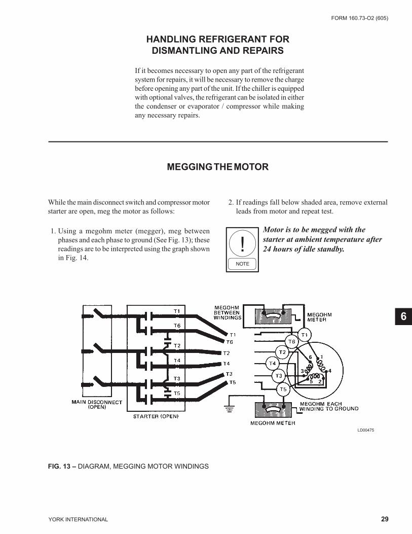
MEGGING THE MOTOR
If it becomes necessary to open any part of the re frig er ant system for repairs, it will be necessary to re move the charge before opening any part of the unit. If the chiller is equipped with optional valves, the refrigerant can be iso lat ed in either the condenser or evaporator / compressor while making any necessary repairs.
While the main disconnect switch and compressor mo tor starter are open, meg the motor as follows:
1. Using a megohm meter (megger), meg between phas es and each phase to ground (See Fig. 13); these read ings are to be interpreted using the graph shown in Fig. 14.
2. If readings fall below shaded area, remove ex ter nal leads from motor and repeat test.
Motor is to be megged with the starter at ambient temperature after 24 hours of idle stand by.
FIG. 13 – DIAGRAM, MEGGING MOTOR WIND INGS
LD00475
6

YORK INTERNATIONAL
FORM 160.73-O2 (605)
30
LD00476
FIG. 14 – MOTOR STARTER TEMPERATURE AND INSULATION RE SIS TANC ES
Min
imum
Insu
latio
n R
esis
tanc
e vs
. Tem
pera
ture
(per
IEEE
Std
43)
Ope
n M
otor
s
Maintenance
TEMPERATURE – °F
MEG
OH
MS

FORM 160.73-O2 (605)
31YORK INTERNATIONAL
CONDENSERS AND EVAPORATORS
GENERAL
Maintenance of condenser and evaporator shells is im- por tant to provide trouble free operation of the chiller. The water side of the tubes in the shell must be kept clean and free from scale. Proper maintenance such as tube cleaning, and testing for leaks, is covered on the fol low ing pages.
CHEMICAL WATER TREATMENT
Since the mineral content of the water circulated through evaporators and condensers varies with almost every source of supply, it is possible that the water be ing used may corrode the tubes or deposit heat re sis tant scale in them. Reliable water treatment com pa nies are available in most larger cities to supply a wa ter treating process which will greatly reduce the cor ro sive and scale form- ing prop er ties of almost any type of water.
As a preventive measure against scale and corrosion and to prolong the life of evaporator and condenser tubes, a chemical analysis of the water should be made pref er a bly before the system is installed. A reliable water treat ment company can be consulted to determine wheth er water treatment is necessary, and if so, to fur nish the proper treatment for the particular water con di tion.
CLEANING EVAPORATOR AND CONDENSER TUBES
EvaporatorIt is diffi cult to determine by any particular test wheth er possible lack of performance of the water evaporator is due to fouled tubes alone or due to a combination of trou bles. Trouble which may be due to fouled tubes is indicated when, over a period of time, the cooling ca pac i ty de creas es and the split (temperature differ-ence between water leaving the evaporator and the refrigerant tem per a ture in the evaporator) increases. A gradual drop-off in cool ing capacity can also be caused by a gradual leak of refrigerant from the system or by a com bi na tion of fouled tubes and shortage of refrigerant charge. An ex ces sive quantity of oil in the evaporator can also con trib ute to erratic performance.
CondenserIn a condenser, trouble due to fouled tubes is usually indicated by a steady rise in head pressure, over a pe ri od of time, accompanied by a steady rise in con dens ing temperature, and noisy operation. These symp toms may also be due to foul gas buildup. Purging will re move the foul gas revealing the effect of fouling.
TUBE FOULING
Fouling of the tubes can be due to deposits of two types as fol lows: 1. Rust or sludge – which fi nds its way into the tubes
and accumulates there. This material usually does not build up on the inner tube surfaces as scale, but does interfere with the heat transfer. Rust or sludge can generally be removed from the tubes by a thor ough brushing process.
2. Scale – due to mineral deposits. These deposits, even though very thin and scarcely detectable upon phys- i cal inspection, are highly resistant to heat trans fer. They can be removed most effectively by cir cu lat ing an acid solution through the tubes.
TUBE CLEANING PROCEDURES
Brush Cleaning of TubesIf the tube consists of dirt and sludge, it can usually be removed by means of the brushing process. Drain the water sides of the circuit to be cleaned (cooling water or chilled water) remove the heads and thoroughly clean each tube with a soft bristle bronze or nylon brush. DO NOT USE A STEEL BRISTLE BRUSH. A steel brush may damage the tubes.
Improved results can be obtained by admitting water into the tube during the cleaning process. This can be done by mounting the brush on a suitable length of 1/8" pipe with a few small holes at the brush end and con nect ing the other end by means of a hose to the water supply.
The tubes should always be brush cleaned before acid cleaning.
ACID CLEANING OF TUBES
If the tubes are fouled with a hard scale deposit, they may require acid cleaning. It is im por tant that before acid clean ing, the tubes be cleaned by the brushing pro cess de scribed above. If the relatively loose foreign material is removed be fore the acid cleaning, the acid so lu tion will have less material to dis solve and fl ush from the tubes with the re sult that a more satisfactory clean ing job will be accomplished with a prob a ble sav ing of time.
Acid cleaning should only be per- formed by an ex pert. Please consult your local water treatment rep re -sen ta tive for as sis tance in removing scale buildup and pre ven ta tive main- te nance pro grams to elim i nate future prob lems.
6
YORK INTERNATIONAL
FORM 160.73-O2 (605)
32
COMMERCIAL ACID CLEANING
In many major cities, commercial organizations now offer a specialized service of acid cleaning evaporators and condensers. If acid cleaning is required, YORK rec om mends the use of this type of organization. The Dow Industries Service Division of the Dow Chemical Com pa ny, Tulsa, Oklahoma, with branches in principal cit ies is one of the most reliable of these companies.
TESTING FOR EVAPORATOR AND CONDENSER TUBE LEAKS
Evaporator and condenser tube leaks in R-134a systems may result in refrigerant leaking into the wa ter circuit, or water leaking into the shell depending on the pres- sure levels. If refrigerant is leaking into the water, it can be de tect ed at the liquid head vents after a pe ri od of shut down. If water is leaking into the re frig er ant, sys tem capacity and effi ciency will drop off sharp ly. If a tube is leaking and water has entered the system, the evaporator and condenser should be valved off from the rest of the water circuit and drained im me di ate ly to pre vent se vere rusting and corrosion. The refrigerant sys tem should then be drained and purged with dry ni- tro gen to prevent severe rusting and corrosion. If a tube leak is in di cat ed, the ex act lo ca tion of the leak may be de ter mined as fol lows:
1. Remove the heads and listen at each section of tubes for a hiss ing sound that would indicate gas leakage. This will assist in locating the section of tubes to be fur ther in ves ti gat ed. If the prob a ble lo ca tion of the leaky tubes has been de ter mined, treat that sec tion in the fol low ing man ner (if the lo ca tion is not defi nite, all the tubes will re quire in ves ti ga tions).
2. Wash off both tube heads and the ends of all tubes with water.
Do not use carbon tetrachloride for this pur pose since its fumes give the same fl ame dis col or a tion that the re frig er ant does.
3. With nitrogen or dry air, blow out the tubes to clear them of traces of re frig er ant laden moisture from the circulation water. As soon as the tubes are clear, a cork should be driven into each end of the tube. Pres-surize the dry system with 50 to 100 PSIG (345 to 690 kPa) of nitrogen. Repeat this with all of the oth er tubes in the sus pect ed sec tion or, if nec es sary, with all the tubes in the evaporator or con dens er. Allow the evaporator or con dens er to re main corked up to 12 to 24 hours be fore pro ceed ing. De pend ing upon the amount of leak age, the corks may blow from the end of a tube, indicating the lo ca tion of the leak age. If not, if will be nec es sary to make a very thor ough test with the leak detector.
4. After the tubes have been corked for 12 to 24 hours, it is recommended that two men working at both ends of the evaporator carefully test each tube – one man removing corks at one end and the other at the op po site end to remove corks and handle the leak de tec tor. Start with the top row of tubes in the sec- tion being investigated. Remove the corks at the ends of one tube simultaneously and insert the ex plor ing tube for 5 seconds – this should be long enough to draw into the detector any refrigerant gas that might have leaked through the tube walls. A fan placed at the end of the evaporator opposite the detector will as sure that any leakage will travel through the tube to the detector.
5. Mark any leaking tubes for later identifi cation.
6. If any of the tube sheet joints are leaking, the leak should be indicated by the detector. If a tube sheet leak is suspected, its exact location may be found by using a soap solution. A continuous buildup of bub bles around a tube indicates a tube sheet leak.
Maintenance
FORM 160.73-O2 (605)
33YORK INTERNATIONAL
COMPRESSOR
ELECTRICAL CONTROLS
Maintenance for the compressor assembly consists of check ing the operation of the oil return system and chang- ing the dehydrator, checking and changing the oil, check- ing and changing the oil fi lters, checking the op er a tion of the oil heater, checking the operation of the oil pump, and observing the operation of the com pres sor.
Internal wearing of compressor parts could be a se ri ous problem caused by improper lubrication, brought about by restricted oil lines, passages, or dirty oil fi l ters. If the unit is shutting down on (HOT) High Oil Tem per a ture
or Low Oil Pressure (OP), change the oil fi lter element. Examine the oil fi lter element for the pres ence of alu- mi num particles. Aluminum gas seal rings can contact the impeller and account for some alu mi num particles to ac cu mu late in the oil fi lter, especially during the initial start up and fi rst several months of op er a tion. How ev er, if aluminum particles continue to ac cu mu late and the same conditions continue to stop the unit operation after a new fi lter is installed, notify the nearest YORK offi ce to re quest the presence of a YORK Service Tech ni cian.
For information covering the OptiView™ Con-trol Center op er a tion, refer to Form 160.54-O1.
6

YORK INTERNATIONAL
FORM 160.73-O2 (605)
34
SECTION 7PREVENTIVE MAINTENANCE
It is the responsibility of the owner to pro vide the nec es -sary daily, monthly and yearly main te nance re quire ments of the system. IM POR TANT – If a unit failure occurs due to improper maintenance during the war ran ty pe ri od; YORK will not be liable for costs in curred to re turn the system to sat is fac to ry op er a tion.
In any operating system it is most im por tant to provide a planned maintenance and inspection of its func tion ing parts to keep it op er at ing at its peak effi ciency. There fore, the following main te nance should be per formed when pre scribed.
COMPRESSOR
1. Oil Filter – When oil pump VSD frequency increases to 55 hz to maintain target oil pressure.
When the oil fi lter is changed, it should be in spect ed thoroughly for any aluminum particles which would indicate possible bearing wear. If alu mi num par ti cles are found this should be brought to the attention of the nearest YORK offi ce for their further in ves ti ga tion and recommendations.
2. Oil Changing – The oil in the com pres sor must be changed annually or earlier if it be comes dark or cloudy. However, quarterly oil analysis can elim i nate the need for an annual change provided the analysis indicates there is no problem with the oil.
COMPRESSOR MOTOR
1. Check motor mounting screws fre quent ly to insure tightness.
2. Meg motor windings annually to check for de te -ri o ra tion of windings.
GREASED BEARINGS ON RELIANCE Q5800 MOTORS
Motor Operation and Maintenance manuals are supplied with the chillers providing maintenance schedules and instructions for the specifi c motors. The following are lubrication schedules for the most common motors:
RAW and Toshiba Motor LubricationFrame 143T thru 256T are furnished with double sealed ball bearings, pre-lubricated prior to installation. Grease fi ttings are not supplied and bearings are designed for long life under standard conditions.Frames 284T thru 587UZ are furnished with double
shielded or open ball or roller bearings. It is necessary to re-lubricate anti-friction bearings periodically. (See Table 4)
Frame Size
Standard 8hr/Day
Continuous 24hr Day
Grease Qty. oz.
143T-256T *7 Years *3 Years *1284TS - 286TS 210 Days 70 Days 1
324TS - 587USS 150 Days 50 Days 2
* - On frame sizes 143T - 256T, changing bearings at these intervals is recommended. However, removing the seal, cleaning and refi lling the bearing and the cavity with recommended grease can re-lubricate these bearings.
Reliance motors in the 5800 frame size are equipped en tire ly with grease-lu bri cat ed ball-bear ings. The fol- low ing out lines the lu bri ca tion re quire ments for these bearings: • The motor bearings are properly lu bri cat ed as re-
ceived from YORK. There is no need to add lu bri cant to the motor bearings at start-up. Too much grease in the motor bear ing cav i ty may cause ex ces sive bear ing tem per a ture.
• If the motor has been in storage for 6 months prior to commissioning, lubricate the motor bearings per the following instructions prior to start-up.
• If the motor is inactive for 30 days, the motor shaft is to be rotated 15 revolutions in order to dis trib ute the grease within the bearing.
• Some bearing squeal may be noted at start-up. This is often due to the bearing cage, as it vibrates against the mov ing bearing elements. This noise should sub-side af ter a few days of operation. In ter mit tent bear-ing squeal is not cause for alarm.
• Use only Texaco Premium RB (Code 1939) grease to lubricate the motor bearings, as in di cat ed in Re- li ance literature for these mo tors. The grease is readi ly available throughout most of the world, from Texaco dis trib u tors – and in Africa, Australia, and the Pa cifi c Rim coun tries from Caltex dis trib u tors. Oth er types of grease may be chemically and me chan i cal ly in-compatible with this Texaco Pre mi um RB grease, and are not to be used.
Preventive Maintenance
TABLE 4 – BEARING LUBRICATION
FORM 160.73-O2 (605)
35YORK INTERNATIONAL
• Add 1.5 cubic inches of Texaco Premium RB grease every 1800 hours of operation of the motor. Do not expect to see grease exiting the grease relief port dur-ing these re-lubrications.
Westinghouse Motor Lubrication:• Re-greasing should occur at 1000 operating hour
intervals. • Westinghouse recommends using Westinghouse
Grease No. 53701. • Motors with shaft diameters less than 2 3/8 inch
require 1 oz of grease per bearing while motors with shaft diameters between 2 3/8 and 3 inches require 1.5 oz.
Recommended greases for standard applications:OPERATING AMBIENT TEMP. -30ºC to 50ºC
Chevron SRI (Chevron)Exxon Unirex #2 (Exxon Corp.)Exxon Polyrex (Exxon Corp.)Shell Dolum R (Shell Oil Co.)
Mixing different greases is not recommended
Additional information on motor lubri-cation and other service issues can be found in the A-C Motors Instruction Manual.
LEAK TESTINGThe unit should be leak tested quarterly. Any leaks found must be repaired immediately.
EVAPORATOR AND CONDENSERThe major portion of maintenance on the condenser and evaporator will deal with the maintaining the water side of the condenser and evaporator in a clean condition.
The use of untreated water in cooling towers, closed water systems, etc. frequently results in one or more of the following:
1. Scale Formation. 2. Corrosion or Rusting. 3. Slime and Algae Formation.
It is therefore to the benefi t of the user to provide for proper water treatment to provide for a longer and more economical life of the equipment. The following rec om men da tion should be followed in determining the con di tion of the water side of the condenser and evaporator tubes.
1. The condenser tubes should be cleaned annually or earlier if conditions warrant. If the tem per a ture dif fer ence between the water off the condenser and the condenser liquid temperature is more than 4°F (2°C) great er than the difference recorded on a new unit, it is a good indication that the condenser tubes re quire clean ing. Refer to the Maintenance section of this manual for condenser tube cleaning instructions.
2. The evaporator tubes under normal cir cum stanc es will not require cleaning. If however the tem per a ture dif fer ence between the refrigerant and the chilled wa ter increases slowly over the operating sea son, it is an indication that the evaporator tubes may be foul ing or that there may be a water bypass in the water box requiring gasket replacement or refrigerant may have leaked from the chiller.
OIL RETURN SYSTEM
1. Change the dehydrator in the oil return system semi- an nu al ly or earlier if the oil return system fails to operate.
2. When the dehydrator is changed, the nozzle of the eductor should be checked for any foreign particles that may be obstructing the jet.
ELECTRICAL CONTROLS
1. All electrical controls should be in spect ed for ob- vi ous malfunctions.
2. It is important that the factory settings of controls (operation and safety) not be changed. If the set tings are changed without YORK’s approval, the warranty will be jeopardized.
7
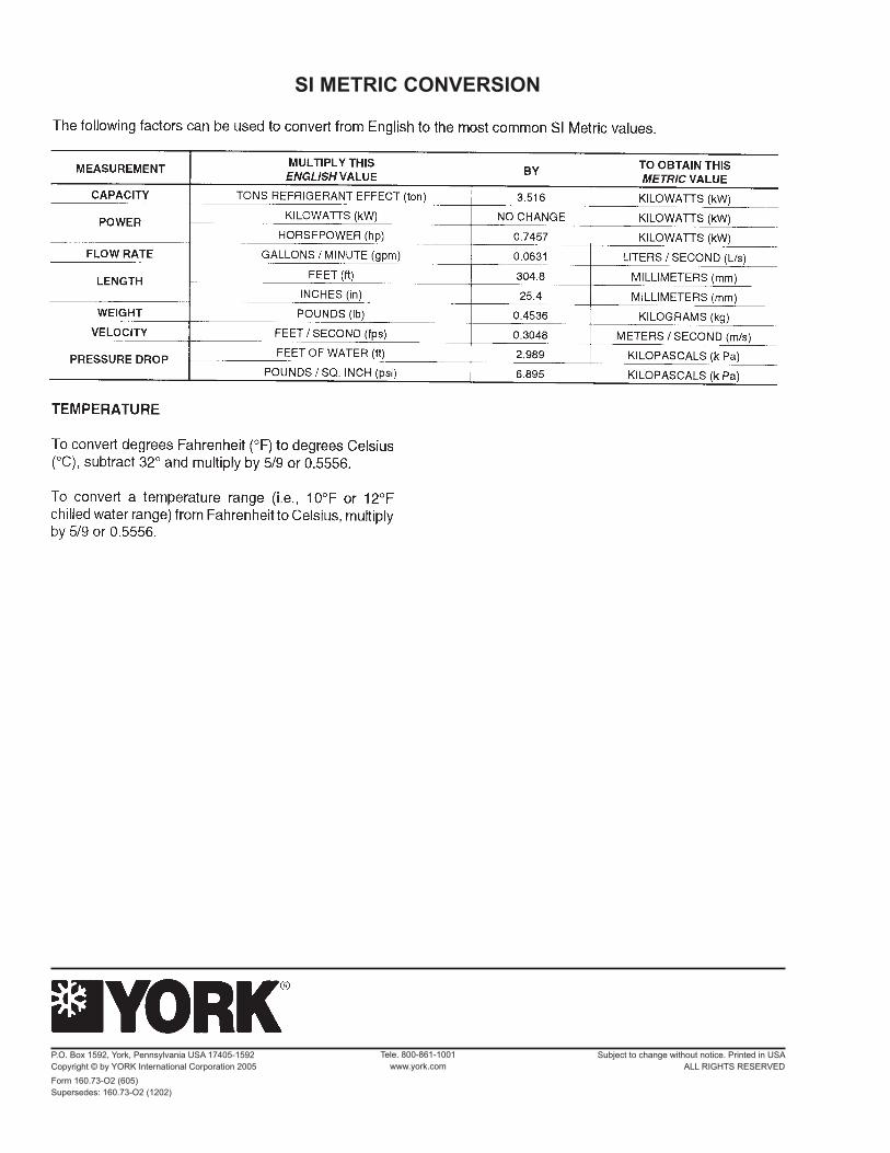
SI METRIC CONVERSION
Tele. 800-861-1001www.york.com
P.O. Box 1592, York, Pennsylvania USA 17405-1592 Subject to change without notice. Printed in USACopyright © by YORK International Corporation 2005 ALL RIGHTS RESERVEDForm 160.73-O2 (605) Supersedes: 160.73-O2 (1202)