Embed Size (px)
Citation preview

The pictures contain also accessories and special equipment which are not included in the standard scope of delivery. Subject to modification.PN 131.01.E05.2010
Liebherr-Werk Ehingen GmbHPostfach 1361, 89582 Ehingen, Germany� +49 7391 5 02-0, Fax +49 7391 5 02-33 99www.liebherr.com, E-Mail: [email protected]
Mobile CraneProduct advantagesMax. lifting capacity: 250 tMax. height under hook: 108 mMax. radius: 92 m
LTM 1250-6.1
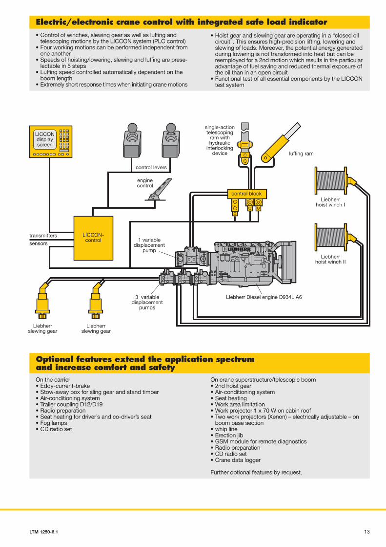
Electric/electronic crane control with integrated safe load indicator• Control of winches, slewing gear as well as luffing and
telescoping motions by the LICCON system (PLC control)• Four working motions can be performed independent from
one another• Speeds of hoisting/lowering, slewing and luffing are prese-
lectable in 5 steps• Luffing speed controlled automatically dependent on the
boom length• Extremely short response times when initiating crane motions
• Hoist gear and slewing gear are operating in a “closed oilcircuit”. This ensures high-precision lifting, lowering andslewing of loads. Moreover, the potential energy generatedduring lowering is not transformed into heat but can bereemployed for a 2nd motion which results in the particularadvantage of fuel saving and reduced thermal exposure ofthe oil than in an open circuit
• Functional test of all essential components by the LICCONtest system
On the carrier• Eddy-current-brake• Stow-away box for sling gear and stand timber• Air-conditioning system• Trailer coupling D12/D19• Radio preparation• Seat heating for driver’s and co-driver’s seat• Fog lamps• CD radio set
On crane superstructure/telescopic boom• 2nd hoist gear• Air-conditioning system• Seat heating• Work area limitation• Work projector 1 x 70 W on cabin roof• Two work projectors (Xenon) – electrically adjustable – on
boom base section• whip line• Erection jib• GSM module for remote diagnostics• Radio preparation• CD radio set• Crane data logger
Further optional features by request.
Optional features extend the application spectrumand increase comfort and safety
Compact, manoeuvrableand weight-optimized• Overall length 17.4 m, carrier 15.3 m long• Large overhang angles, front up to 17°, rear up to 19°• Smallest turning radius by 5-axle steering
(13.1 m over carrier)• Axle load equalization (12 t) due to hydropneumatic
suspension ”Niveaumatik”• In addition to service and parking brake, the following
sustained-action brakes are part of the standard equipmentfor safe travel: retarder in the automatic transmission andengine brake as exhaust brake with Liebherr auxiliary brakesystem by valve control (ZBS)
Variable drive and steering concept
• Standard 5-axle steering, 5th and 6th axle are also steerableindependant from axles 1 – 3. During crab steering/diagonaldisplacement, axles 3 and 4 are raised hydraulically
• Drive 12 x 6, axles 1, 5 and 6 are driven• Drive 12 x 8, axles 1, 4, 5 and 6 are driven, 4th axle activatable
for off-road travel• Automated gear system ZF-TC-TRONIC with converter and
retarder; 12 forward and 2 reversed speeds, automatedcontrol
• Reduced fuel consumption due to a great number of speeds,sensitive maneuvering due to converter
• Robust transfer case with transfer differential• Driving axles with differential locks for transverse locking in
off-road ratio
Setting crane on outriggers –quick, convenient and safe• Supporting basis 8.84 m x 8.5 m or 8.84 m x 5.58 m• Fixed lightweight supporting pads (plastic) with lateral
compensation• Supporting rams with 600 mm travel• Level control of supporting system, all-automatic levelling
of the crane during the supporting procedure by “push-button control”
• 2 x 9° lateral inclination even with locked suspension• Inclinometer (electronic inclination indicator) with two displays
on the carrier and one display on the LICCON monitor inthe crane cab
• 2 supporting force indicators on the control panels on thecarrier and on the LICCON monitor
• Operation of the outrigger system in accordance with therules for the prevention of accidents
control block
LICCONdisplayscreen
luffing ram
single-actiontelescoping
ram withhydraulic
interlockingdevice
control levers
3 variabledisplacement
pumps
Liebherr Diesel engine D934L A6
transmitters
Liebherrslewing gear
1 variabledisplacement
pumpsensors
Liebherrhoist winch I
Liebherrhoist winch II
enginecontrol
Liebherrslewing gear
LICCON-control
15,29
17.41
2.13
4.0
19°17°16.00 R 25 12 t 12 t 12 t 12 t 12 t 12 t
600
8.5
5.58
3.0
6.56
8.86
R=11.40
0.6R =
6.4
2R=13.05
R=14.14
132 LTM 1250-6.1 LTM 1250-6.1
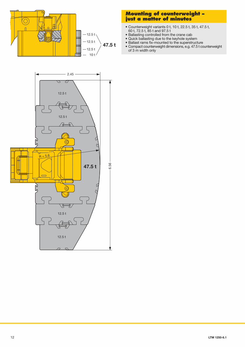
Mounting of counterweight –just a matter of minutes• Counterweight variants 0 t, 10 t, 22.5 t, 35 t, 47.5 t,
60 t, 72.5 t, 85 t and 97.5 t• Ballasting controlled from the crane cab• Quick ballasting due to the keyhole system• Ballast rams fix-mounted to the superstructure• Compact counterweight dimensions, e.g. 47.5 t counterweight
of 3 m width only
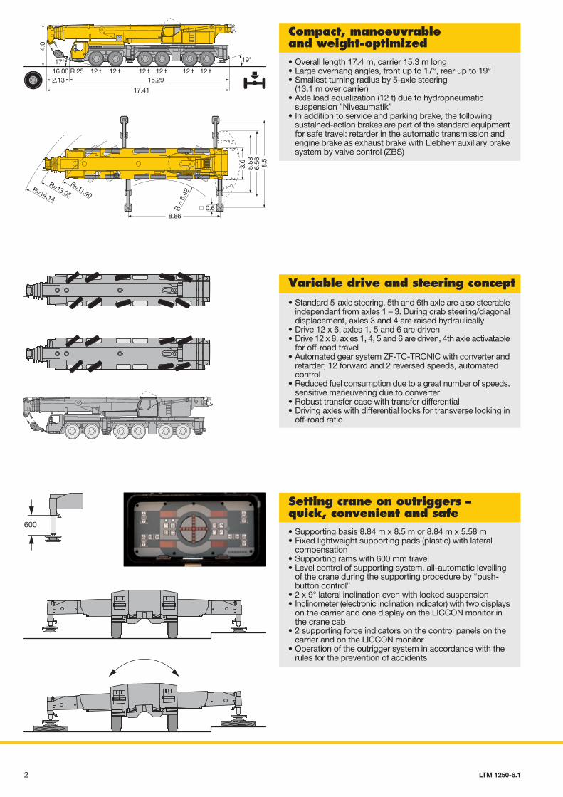
• 72 m long, 6-section telescopic boom• Features of the new boom technology:
- optimimized, oviform boom profile – patented internal interlocking system of the telescopes
- automatic telescopic system “Telematic”• Telescopic boom with electronically controlled
telescoping system• Boom bearings of low maintenance polyamide slide blocks• Outstanding lifting capacities, e.g.
84 t at 10 m radius38 t at 20 m radius
15.4 t at 40 m radius8.4 t at 60 m radius2.1 t at 80 m radius1.1 t at 92 m radius
• 8-cylinder Liebherr turbo-charged Diesel engine typeD9508 A7, 450 kW/612 h.p., exhaust emissions acc. to97/68/EG stage 3 and EPA/CARB Tier 3, energy-saving,robust and reliable, electronic engine management
• Automated gear system ZF-TC-TRONIC with converter andretarder; 12 forward and 2 reversed speeds, automatedcontrol
• Robust transfer case with transfer differential• Robust crane axles, welded design• Max. driving speed 76 km/h, max. gradability 43 %
• Steel-fabricated, corrosion resistant cab, cataphoretic dip-primed, front section on rubber shock absorbers, rear sectionon hydraulic dampers, internal sound and heat absorbingpanelling, modern interior design of outstanding functionality
• Safety glass all-round, green-tinted heat-isolating front andside window panes, electric window lifters
• Standardised digital operating and control elements arrangedin an operator-friendly halfround shape
• Additional heater with engine preheating
• Weight-optimized and low maintenance axles of high-tensilesteel, perfect track-keeping and lateral stability due to specialcontrol linkage arrangement
• The low maintenance steering nuckles are steel and rubbermounted, thus bearing failures are practically ruled out
• The perfected and robust axles are manufactured in largeseries and are part of the trouble-free components of amobile crane
• The cardan shafts are maintenance-free. The 70° diagonaltoothing and 4 fixing bolts enable easy and fast fitting of thecardan shafts
Ultramodern boom technology Powerful carrier drive
Modern and comfortabledriver’s cab
Outstanding carrier technologyfor road and off-road operation
• Steel-fabricated and corrosion-resistant crane cab, powder-coated, with internal sound and heat absorbing panelling,modern interior design, tinted panes all-round, front knockoutwindow with large windscreen wiper and washer, skylightof bullet-proof glass with large windscreen wiper and washer,roller blinds on front window and skylight, space savingsliding door
• Additional heaterwith engine preheating
• Pneumatic operated footboard for safe access to the carrier• Crane cab tiltable by 20° to the rear
• Crane engine: 4-cylinder Liebherr turbo-charged Dieselengine type D934L A6 of 180 KW/245 h.p., robust andreliable,exhaust emissions acc. to 97/68/EG stage 3 andEPA/CARB Tier 3, electronic engine management, optimizedfuel consumption, exhaust gas system of stainless steel,very efficient noise abatment of the dieselhydraulic cranedrive
• Slewing rim, slewing gear and the winches are self-manufactured components specially matched for theapplication on mobile cranes
• The centralized lubricating system for slewing rim, boombearing application, luffing rams and winch bearings is astandard feature
Crane cab of modern design Crane drive withfield-proven components
• Maintenance-free suspension rams, free from lateral forcesand protected against damage by synthetic tubes
• Level adjustment (suspension set to “travel mode”) can beperformed automatically from any position by push-buttoncontrol
• Stable cornering ability of the crane due to cross mountingof the hydropneumatic suspension
• Axle locking system (blocking of the suspension for travellingwith equipment) integrated into the suspension rams andcontrollable from the driver’s cab
• Carrier, superstructure and telescopic boom in light-gaugedesign, calculated by the F.E.M. method, thus weight-optimized and particularly torsonally rigid
• Tensile property of the material with high safety factorsthrough the application of STE 960 (960 N/mm2) for allsupporting members. Telescopic boom bottom shell of ultra-high tensile steel S 1100 QL (1100 N/mm2)
• Weldment joints of oustanding quality are performed bycomputer-aided welding machines
• The weld quality is documented by ultrasonic test
Crane- and road-preservingNiveaumatik suspension
Weight-optimized steel structure
6.56
2.45
R = 5.6
12.5 t
12.5 t
12.5 t
12.5 t
47.5 t
12.5 t
12.5 t
12.5 t
10 t
47.5 t
3 412 LTM 1250-6.1 LTM 1250-6.1 LTM 1250-6.1
Mounting of counterweight –just a matter of minutes• Counterweight variants 0 t, 10 t, 22.5 t, 35 t, 47.5 t,
60 t, 72.5 t, 85 t and 97.5 t• Ballasting controlled from the crane cab• Quick ballasting due to the keyhole system• Ballast rams fix-mounted to the superstructure• Compact counterweight dimensions, e.g. 47.5 t counterweight
of 3 m width only
• 72 m long, 6-section telescopic boom• Features of the new boom technology:
- optimimized, oviform boom profile – patented internal interlocking system of the telescopes
- automatic telescopic system “Telematic”• Telescopic boom with electronically controlled
telescoping system• Boom bearings of low maintenance polyamide slide blocks• Outstanding lifting capacities, e.g.
84 t at 10 m radius38 t at 20 m radius
15.4 t at 40 m radius8.4 t at 60 m radius2.1 t at 80 m radius1.1 t at 92 m radius
• 8-cylinder Liebherr turbo-charged Diesel engine typeD9508 A7, 450 kW/612 h.p., exhaust emissions acc. to97/68/EG stage 3 and EPA/CARB Tier 3, energy-saving,robust and reliable, electronic engine management
• Automated gear system ZF-TC-TRONIC with converter andretarder; 12 forward and 2 reversed speeds, automatedcontrol
• Robust transfer case with transfer differential• Robust crane axles, welded design• Max. driving speed 76 km/h, max. gradability 43 %
• Steel-fabricated, corrosion resistant cab, cataphoretic dip-primed, front section on rubber shock absorbers, rear sectionon hydraulic dampers, internal sound and heat absorbingpanelling, modern interior design of outstanding functionality
• Safety glass all-round, green-tinted heat-isolating front andside window panes, electric window lifters
• Standardised digital operating and control elements arrangedin an operator-friendly halfround shape
• Additional heater with engine preheating
• Weight-optimized and low maintenance axles of high-tensilesteel, perfect track-keeping and lateral stability due to specialcontrol linkage arrangement
• The low maintenance steering nuckles are steel and rubbermounted, thus bearing failures are practically ruled out
• The perfected and robust axles are manufactured in largeseries and are part of the trouble-free components of amobile crane
• The cardan shafts are maintenance-free. The 70° diagonaltoothing and 4 fixing bolts enable easy and fast fitting of thecardan shafts
Ultramodern boom technology Powerful carrier drive
Modern and comfortabledriver’s cab
Outstanding carrier technologyfor road and off-road operation
• Steel-fabricated and corrosion-resistant crane cab, powder-coated, with internal sound and heat absorbing panelling,modern interior design, tinted panes all-round, front knockoutwindow with large windscreen wiper and washer, skylightof bullet-proof glass with large windscreen wiper and washer,roller blinds on front window and skylight, space savingsliding door
• Additional heaterwith engine preheating
• Pneumatic operated footboard for safe access to the carrier• Crane cab tiltable by 20° to the rear
• Crane engine: 4-cylinder Liebherr turbo-charged Dieselengine type D934L A6 of 180 KW/245 h.p., robust andreliable,exhaust emissions acc. to 97/68/EG stage 3 andEPA/CARB Tier 3, electronic engine management, optimizedfuel consumption, exhaust gas system of stainless steel,very efficient noise abatment of the dieselhydraulic cranedrive
• Slewing rim, slewing gear and the winches are self-manufactured components specially matched for theapplication on mobile cranes
• The centralized lubricating system for slewing rim, boombearing application, luffing rams and winch bearings is astandard feature
Crane cab of modern design Crane drive withfield-proven components
• Maintenance-free suspension rams, free from lateral forcesand protected against damage by synthetic tubes
• Level adjustment (suspension set to “travel mode”) can beperformed automatically from any position by push-buttoncontrol
• Stable cornering ability of the crane due to cross mountingof the hydropneumatic suspension
• Axle locking system (blocking of the suspension for travellingwith equipment) integrated into the suspension rams andcontrollable from the driver’s cab
• Carrier, superstructure and telescopic boom in light-gaugedesign, calculated by the F.E.M. method, thus weight-optimized and particularly torsonally rigid
• Tensile property of the material with high safety factorsthrough the application of STE 960 (960 N/mm2) for allsupporting members. Telescopic boom bottom shell of ultra-high tensile steel S 1100 QL (1100 N/mm2)
• Weldment joints of oustanding quality are performed bycomputer-aided welding machines
• The weld quality is documented by ultrasonic test
Crane- and road-preservingNiveaumatik suspension
Weight-optimized steel structure
6.56
2.45
R = 5.6
12.5 t
12.5 t
12.5 t
12.5 t
47.5 t
12.5 t
12.5 t
12.5 t
10 t
47.5 t
3 412 LTM 1250-6.1 LTM 1250-6.1 LTM 1250-6.1
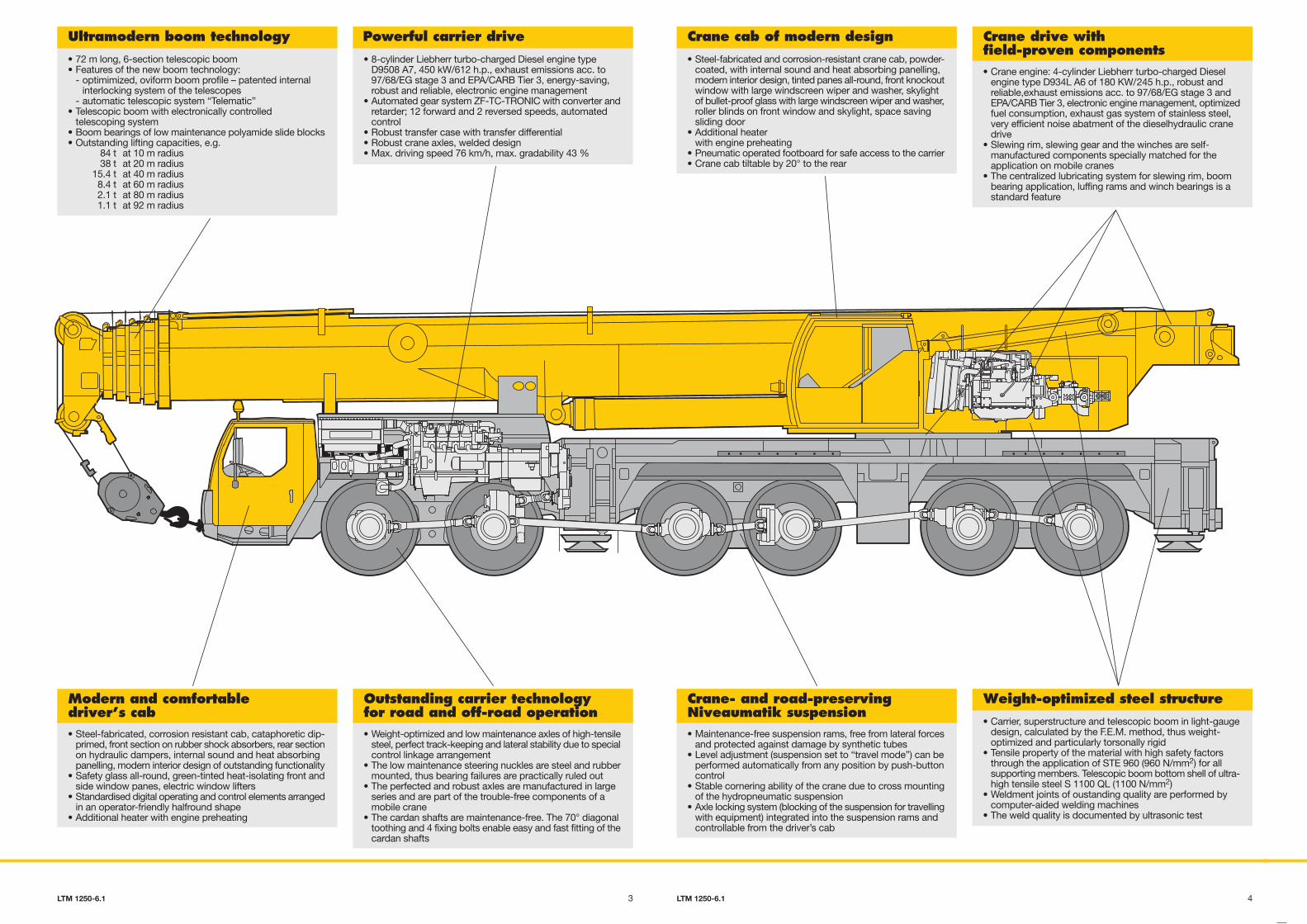
• Modern and comfortable driver’s cab of outstandingfunctionality and convincing design
• Ergonomically arranged operating and display units for safeand convenient handling at permanent operation
• Digital display and keyboard units interconnected with thefunction blocks by data bus technique
• Air-cushioned driver’s and co-driver’s seat with head rests,driver’s seat with lumber support
• Auxiliary heater with engine preheating• Safety belts for driver and co-driver• Height and inclination adjustable steering wheel• Heated and electrically adjustable rear mirrors• Side panes with electric window lifters• 3 automatic windscreen wipers with washing device and
intermittent control• Delayed disconnection or interior lighting• Various racks and boxes• Radio preparation
Comfortable driver’s cab ofoutstanding functionality
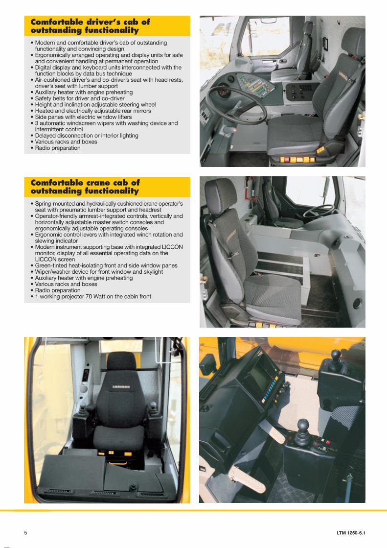
• Spring-mounted and hydraulically cushioned crane operator’sseat with pneumatic lumber support and headrest
• Operator-friendly armrest-integrated controls, vertically andhorizontally adjustable master switch consoles andergonomically adjustable operating consoles
• Ergonomic control levers with integrated winch rotation andslewing indicator
• Modern instrument supporting base with integrated LICCONmonitor, display of all essential operating data on theLICCON screen
• Green-tinted heat-isolating front and side window panes• Wiper/washer device for front window and skylight• Auxiliary heater with engine preheating• Various racks and boxes• Radio preparation• 1 working projector 70 Watt on the cabin front
Comfortable crane cab ofoutstanding functionality
• The electric and electronic components are interconnectedby the latest data bus transmission technique
• Instead of the traditional electric wiring, the data transmissionto the individual function blocks is performed digitally justby a few data cables, thus improved reliability due toessentially less contacts
• Self-manufactured Liebherr bus systems (LSB), speciallyadapted to the requirements of a mobile crane
• Diesel engine and automatic transmission are controlled bya CAN data bus. The all electronic drive management reducesfuel consumption and improves the exhaust gas emission
• The electric systems of the carrier and crane as well as ofall cockpit functions, the outrigger system and sensor systemof the boom are interconnected by 4 Liebherr system busses
• The control of the function blocks is realized by I/A modulesthe programming of which is performed by means of theLiebherr system busses. The control intelligence is integratedinto the LICCON central unit
• Comprehensive diagnostic facilities, quick error localization,operating error display
• Test programs for functional test of keyboard and displayunit as well as for the test of the control units for engine andtransmission management, additional Liebherr brake system,hydraulic ventilator, hydraulic suspension and outriggercontrol panels
• The new data bus technique distinctively increasesfunctionality and efficiency of the mobile crane
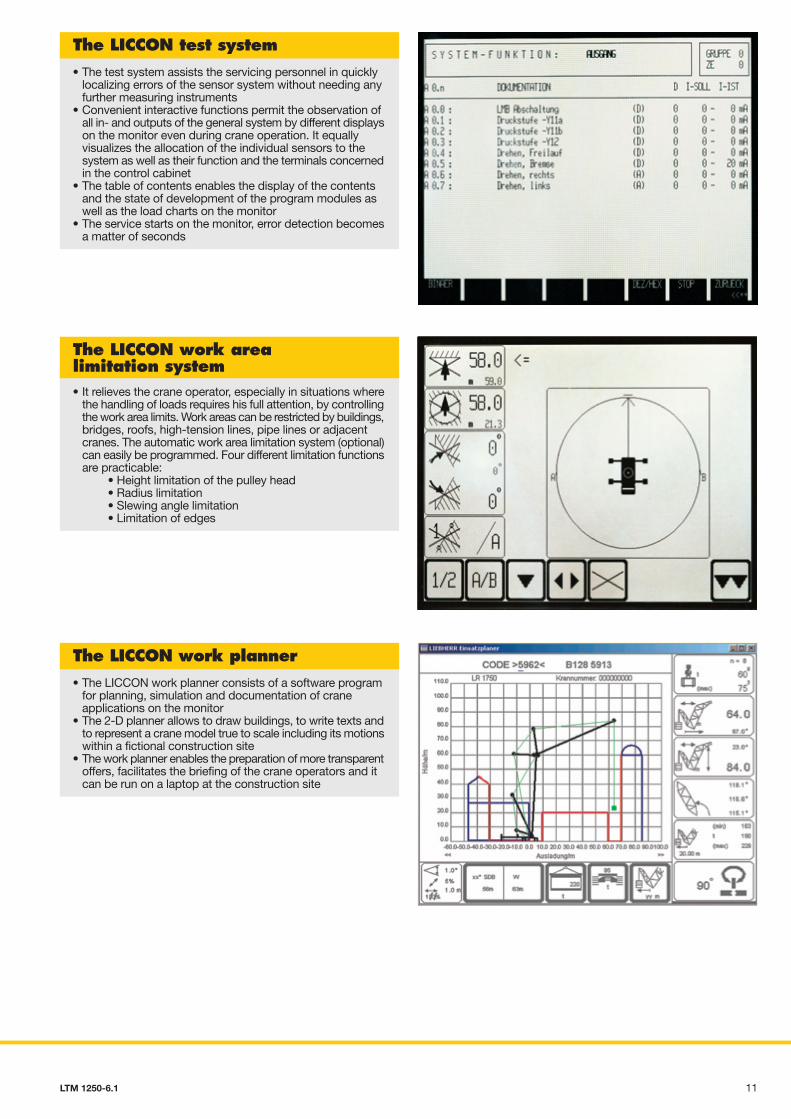
• The test system assists the servicing personnel in quicklylocalizing errors of the sensor system without needing anyfurther measuring instruments
• Convenient interactive functions permit the observation ofall in- and outputs of the general system by different displayson the monitor even during crane operation. It equallyvisualizes the allocation of the individual sensors to thesystem as well as their function and the terminals concernedin the control cabinet
• The table of contents enables the display of the contentsand the state of development of the program modules aswell as the load charts on the monitor
• The service starts on the monitor, error detection becomesa matter of seconds
The LICCON test system
• It relieves the crane operator, especially in situations wherethe handling of loads requires his full attention, by controllingthe work area limits. Work areas can be restricted by buildings,bridges, roofs, high-tension lines, pipe lines or adjacentcranes. The automatic work area limitation system (optional)can easily be programmed. Four different limitation functionsare practicable:
• Height limitation of the pulley head• Radius limitation• Slewing angle limitation• Limitation of edges
The LICCON work arealimitation system
• The LICCON work planner consists of a software programfor planning, simulation and documentation of craneapplications on the monitor
• The 2-D planner allows to draw buildings, to write texts andto represent a crane model true to scale including its motionswithin a fictional construction site
• The work planner enables the preparation of more transparentoffers, facilitates the briefing of the crane operators and itcan be run on a laptop at the construction site
The LICCON work planner
LSB 3
LSB 4
LSB 1
CAN-Bus
3a 3 81
22a
1a
16
22
LSB 1
17
15
76
5
18
6 115 LTM 1250-6.1 LTM 1250-6.1 LTM 1250-6.1
• Modern and comfortable driver’s cab of outstandingfunctionality and convincing design
• Ergonomically arranged operating and display units for safeand convenient handling at permanent operation
• Digital display and keyboard units interconnected with thefunction blocks by data bus technique
• Air-cushioned driver’s and co-driver’s seat with head rests,driver’s seat with lumber support
• Auxiliary heater with engine preheating• Safety belts for driver and co-driver• Height and inclination adjustable steering wheel• Heated and electrically adjustable rear mirrors• Side panes with electric window lifters• 3 automatic windscreen wipers with washing device and
intermittent control• Delayed disconnection or interior lighting• Various racks and boxes• Radio preparation
Comfortable driver’s cab ofoutstanding functionality
• Spring-mounted and hydraulically cushioned crane operator’sseat with pneumatic lumber support and headrest
• Operator-friendly armrest-integrated controls, vertically andhorizontally adjustable master switch consoles andergonomically adjustable operating consoles
• Ergonomic control levers with integrated winch rotation andslewing indicator
• Modern instrument supporting base with integrated LICCONmonitor, display of all essential operating data on theLICCON screen
• Green-tinted heat-isolating front and side window panes• Wiper/washer device for front window and skylight• Auxiliary heater with engine preheating• Various racks and boxes• Radio preparation• 1 working projector 70 Watt on the cabin front
Comfortable crane cab ofoutstanding functionality
• The electric and electronic components are interconnectedby the latest data bus transmission technique
• Instead of the traditional electric wiring, the data transmissionto the individual function blocks is performed digitally justby a few data cables, thus improved reliability due toessentially less contacts
• Self-manufactured Liebherr bus systems (LSB), speciallyadapted to the requirements of a mobile crane
• Diesel engine and automatic transmission are controlled bya CAN data bus. The all electronic drive management reducesfuel consumption and improves the exhaust gas emission
• The electric systems of the carrier and crane as well as ofall cockpit functions, the outrigger system and sensor systemof the boom are interconnected by 4 Liebherr system busses
• The control of the function blocks is realized by I/A modulesthe programming of which is performed by means of theLiebherr system busses. The control intelligence is integratedinto the LICCON central unit
• Comprehensive diagnostic facilities, quick error localization,operating error display
• Test programs for functional test of keyboard and displayunit as well as for the test of the control units for engine andtransmission management, additional Liebherr brake system,hydraulic ventilator, hydraulic suspension and outriggercontrol panels
• The new data bus technique distinctively increasesfunctionality and efficiency of the mobile crane
• The test system assists the servicing personnel in quicklylocalizing errors of the sensor system without needing anyfurther measuring instruments
• Convenient interactive functions permit the observation ofall in- and outputs of the general system by different displayson the monitor even during crane operation. It equallyvisualizes the allocation of the individual sensors to thesystem as well as their function and the terminals concernedin the control cabinet
• The table of contents enables the display of the contentsand the state of development of the program modules aswell as the load charts on the monitor
• The service starts on the monitor, error detection becomesa matter of seconds
The LICCON test system
• It relieves the crane operator, especially in situations wherethe handling of loads requires his full attention, by controllingthe work area limits. Work areas can be restricted by buildings,bridges, roofs, high-tension lines, pipe lines or adjacentcranes. The automatic work area limitation system (optional)can easily be programmed. Four different limitation functionsare practicable:
• Height limitation of the pulley head• Radius limitation• Slewing angle limitation• Limitation of edges
The LICCON work arealimitation system
• The LICCON work planner consists of a software programfor planning, simulation and documentation of craneapplications on the monitor
• The 2-D planner allows to draw buildings, to write texts andto represent a crane model true to scale including its motionswithin a fictional construction site
• The work planner enables the preparation of more transparentoffers, facilitates the briefing of the crane operators and itcan be run on a laptop at the construction site
The LICCON work planner
LSB 3
LSB 4
LSB 1
CAN-Bus
3a 3 81
22a
1a
16
22
LSB 1
17
15
76
5
18
6 115 LTM 1250-6.1 LTM 1250-6.1 LTM 1250-6.1

• The electric and electronic components are interconnectedby the latest data bus transmission technique
• Instead of the traditional electric wiring, the data transmissionto the individual function blocks is performed digitally justby a few data cables, thus improved reliability due toessentially less contacts
• Self-manufactured Liebherr bus systems (LSB), speciallyadapted to the requirements of a mobile crane
• Diesel engine and automatic transmission are controlled bya CAN data bus. The all electronic drive management reducesfuel consumption and improves the exhaust gas emission
• The electric systems of the carrier and crane as well as ofall cockpit functions, the outrigger system and sensor systemof the boom are interconnected by 4 Liebherr system busses
• The control of the function blocks is realized by I/A modulesthe programming of which is performed by means of theLiebherr system busses. The control intelligence is integratedinto the LICCON central unit
• Comprehensive diagnostic facilities, quick error localization,operating error display
• Test programs for functional test of keyboard and displayunit as well as for the test of the control units for engine andtransmission management, additional Liebherr brake system,hydraulic ventilator, hydraulic suspension and outriggercontrol panels
• The new data bus technique distinctively increasesfunctionality and efficiency of the mobile crane
Legend:LSB - Liebherr system bus 1LSB - Liebherr system bus 2LSB - Liebherr system bus 3LSB - Liebherr system bus 4CAN - BusSCI - serial communication interface
1 Input/output module for control of the suspension, LiebherrDiesel engine, automatic transmission, control functions,pneumatic control of brake functions
1a Instruments keyboard unit in driver’s cab2 Input/output module for differential locks, display functions2a Instruments keyboard unit in driver’s cab3 Input/output module for outrigger system - right3a Control unit for outrigger system - right4 Input/output module for outrigger system - left4a Control unit for outriggers system - left5 Input/output module for engine brake, cruise controller, speed
setter, control of Diesel engine (steering column switch right)and automatic transmission
6 Control of automatic transmission
7 Control of injection pump – Liebherr Diesel engine/carrier8 Slewing sensor in slipring unit9 Connection of Liebherr system bus (LSB 1, 2, 3, 4)10 LICCON central unit11 LICCON monitor in crane cab12 Length sensor and cable drum/energy cable for interlocking
gripper/telescopic boom13 Inductive sensors (12 x)14 Angle sensor on base section15 Cable drum for items 16, 17, 18 and for luffing jib16 Wind sensor17 Hoist limit switch18 Angle sensor19 Input/output module for electronic control of Diesel
engine/superstructure, air flap, ventilator clutch, exhaustflap
20 Control injection pump – Liebherr Dieselengine/superstructure
21 Control lever22 Pressure sensor (4 x) for output management and LMB
(safe load indicator)
LSB 3
LSB 4
LSB 1
CAN-Bus
LSB 2
CAN-Bus
9
20
4 4a
3a 3 81
22a
1a2121
16
22
LSB 1
17
15
76
12
14
19
5
11
10
18
13
76 LTM 1250-6.1 LTM 1250-6.1
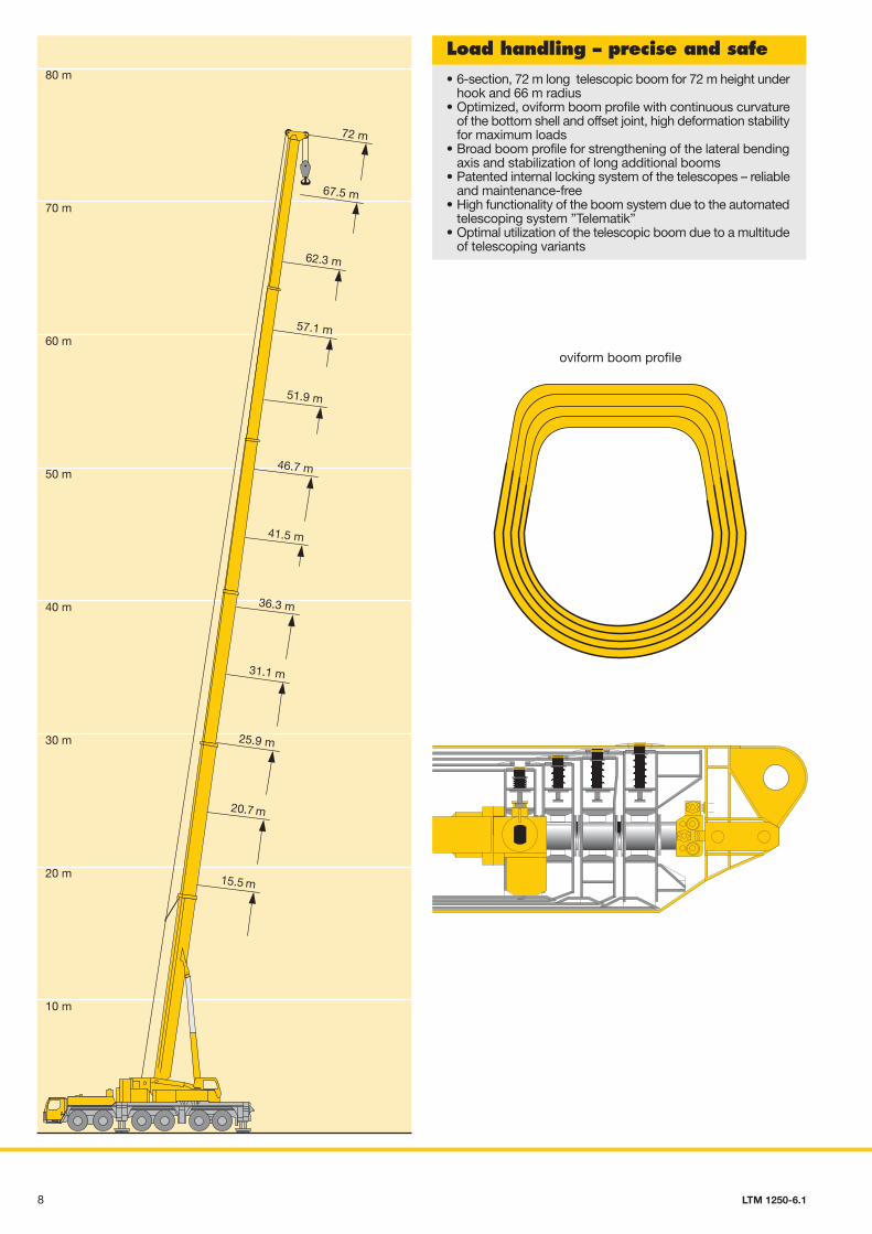
• 6-section, 72 m long telescopic boom for 72 m height underhook and 66 m radius
• Optimized, oviform boom profile with continuous curvatureof the bottom shell and offset joint, high deformation stabilityfor maximum loads
• Broad boom profile for strengthening of the lateral bendingaxis and stabilization of long additional booms
• Patented internal locking system of the telescopes – reliableand maintenance-free
• High functionality of the boom system due to the automatedtelescoping system ”Telematik”
• Optimal utilization of the telescopic boom due to a multitudeof telescoping variants
Load handling – precise and safe
oviform boom profile
70 m
• Telescopic boom T, 15.5 m – 72 m• Swing-away jib K, 12.2 m long, biparted swing-away jib K,
12.2 m – 22 m long, extendable up to 36 m, mountable at0°, 20° or 40°
• Special swing-away jib, 3.4 m long• Fixed lattice jib TF, 14 m – 42 m, mountable at 0°, 20° or 40°
to the 51.9 m – 72 m long telescopic boom• Luffing lattice jib TN, 17.5 m – 70 m, mountable on the
15.4 m – 67.5 m long telescopic boom with continuousinclination between 82° and 68°
• Intermediate sections TF and TN equipment identical andcan be slid into one another for transportation
Multi-variable boom configuration system
• Jib A-frames with T-adapter and N-base section form acomplete transport unit and can be mounted with just 4 pins
• Easy-to-rig stay rods which remain on the intermediatesections during transportation
• Auxiliary winch on the superstructure for easy reeving of thehoist and luffing ropes
• Rigging of the lattice jib is practicable in suspended conditionon restricted sites
• Winch 2 for luffing operation of the jib• Continuous load capacity interpolation during luffing of the
boom combinations TN between 82° and 68° inclination ofthe telescopic boom
15.5 m
20.7 m
25.9 m
31.1 m
36.3 m
41.5 m
46.7 m
51.9 m
57.1 m
62.3 m
72 m
67.5 m
60 m
50 m
40 m
30 m
20 m
10 m
80 m
68°
82°
100 m
90 m
80 m
70 m
60 m
50 m
40 m
30 m
20 m
10 m
110 m
120 m
T TK TF TN
98 LTM 1250-6.1 LTM 1250-6.1

• Standard application programs: Safe load indicator (LMB),configuration program with configuration image, telescopingprogram with telescoping image, supporting force display,control parameter program, test system; and as an option,the work area limitation and the LICCON work planner
• Setting of the crane configuration by convenientinteractive functions
• Safe and reliable acknowledement of the craneconfiguration set
• Representation of all essential data by graphic symbols onthe operating image
• With integrated wind speed control• Reliable cut-off device in the event of exceeding the
admissible load moments• Safe working load values for any intermediate boom length• Winch indications for ultra-precise lifting/lowering of the load
LICCON computer system for controland monitoring functions
Legend:LSB - Liebherr system bus 1LSB - Liebherr system bus 2LSB - Liebherr system bus 3LSB - Liebherr system bus 4CAN - BusSCI - serial communication interface
1 Input/output module for control of the suspension, LiebherrDiesel engine, automatic transmission, control functions,pneumatic control of brake functions
1a Instruments keyboard unit in driver’s cab2 Input/output module for differential locks, display functions2a Instruments keyboard unit in driver’s cab3 Input/output module for outrigger system - right3a Control unit for outrigger system - right4 Input/output module for outrigger system - left4a Control unit for outriggers system - left5 Input/output module for engine brake, cruise controller, speed
setter, control of Diesel engine (steering column switch right)and automatic transmission
6 Control of automatic transmission
• Telescoping by single-stage hydraulic ram with hydraulicdriving tenons (patented internal interlocking system)
• Telescoping procedure controllable by convenient operator’sguide on the monitor, precise approach of the interlockingpositions
• Telescopable loads are displayed on theLICCON operating image
• Rapid-cycle telescoping system with “automatic mode”, i.e.all automatic telescoping of the boom to the desired length
• Particularly compact and light-weight telescopic system,thus increased lifting capacities specially with long boomsat large radii
• Automatic cushioning in end positions during telescopingand retracting for the preservation of the structural members
LICCON-assisted telescoping system
7 Control of injection pump – Liebherr Diesel engine/carrier8 Slewing sensor in slipring unit9 Connection of Liebherr system bus (LSB 1, 2, 3, 4)10 LICCON central unit11 LICCON monitor in crane cab12 Length sensor and cable drum/energy cable for interlocking
gripper/telescopic boom13 Inductive sensors (12 x)14 Angle sensor on base section15 Cable drum for items 16, 17, 18 and for luffing jib16 Wind sensor17 Hoist limit switch18 Angle sensor19 Input/output module for electronic control of Diesel
engine/superstructure, air flap, ventilator clutch, exhaustflap
20 Control injection pump – Liebherr Dieselengine/superstructure
21 Control lever22 Pressure sensor (4 x) for output management and LMB
(safe load indicator)
LSB 2
CAN-Bus
9
20
4 4a
2121
12
14
19
11
10
13
710 LTM 1250-6.1 LTM 1250-6.1
• Modern and comfortable driver’s cab of outstandingfunctionality and convincing design
• Ergonomically arranged operating and display units for safeand convenient handling at permanent operation
• Digital display and keyboard units interconnected with thefunction blocks by data bus technique
• Air-cushioned driver’s and co-driver’s seat with head rests,driver’s seat with lumber support
• Auxiliary heater with engine preheating• Safety belts for driver and co-driver• Height and inclination adjustable steering wheel• Heated and electrically adjustable rear mirrors• Side panes with electric window lifters• 3 automatic windscreen wipers with washing device and
intermittent control• Delayed disconnection or interior lighting• Various racks and boxes• Radio preparation
Comfortable driver’s cab ofoutstanding functionality
• Spring-mounted and hydraulically cushioned crane operator’sseat with pneumatic lumber support and headrest
• Operator-friendly armrest-integrated controls, vertically andhorizontally adjustable master switch consoles andergonomically adjustable operating consoles
• Ergonomic control levers with integrated winch rotation andslewing indicator
• Modern instrument supporting base with integrated LICCONmonitor, display of all essential operating data on theLICCON screen
• Green-tinted heat-isolating front and side window panes• Wiper/washer device for front window and skylight• Auxiliary heater with engine preheating• Various racks and boxes• Radio preparation• 1 working projector 70 Watt on the cabin front
Comfortable crane cab ofoutstanding functionality
• The electric and electronic components are interconnectedby the latest data bus transmission technique
• Instead of the traditional electric wiring, the data transmissionto the individual function blocks is performed digitally justby a few data cables, thus improved reliability due toessentially less contacts
• Self-manufactured Liebherr bus systems (LSB), speciallyadapted to the requirements of a mobile crane
• Diesel engine and automatic transmission are controlled bya CAN data bus. The all electronic drive management reducesfuel consumption and improves the exhaust gas emission
• The electric systems of the carrier and crane as well as ofall cockpit functions, the outrigger system and sensor systemof the boom are interconnected by 4 Liebherr system busses
• The control of the function blocks is realized by I/A modulesthe programming of which is performed by means of theLiebherr system busses. The control intelligence is integratedinto the LICCON central unit
• Comprehensive diagnostic facilities, quick error localization,operating error display
• Test programs for functional test of keyboard and displayunit as well as for the test of the control units for engine andtransmission management, additional Liebherr brake system,hydraulic ventilator, hydraulic suspension and outriggercontrol panels
• The new data bus technique distinctively increasesfunctionality and efficiency of the mobile crane
• The test system assists the servicing personnel in quicklylocalizing errors of the sensor system without needing anyfurther measuring instruments
• Convenient interactive functions permit the observation ofall in- and outputs of the general system by different displayson the monitor even during crane operation. It equallyvisualizes the allocation of the individual sensors to thesystem as well as their function and the terminals concernedin the control cabinet
• The table of contents enables the display of the contentsand the state of development of the program modules aswell as the load charts on the monitor
• The service starts on the monitor, error detection becomesa matter of seconds
The LICCON test system
• It relieves the crane operator, especially in situations wherethe handling of loads requires his full attention, by controllingthe work area limits. Work areas can be restricted by buildings,bridges, roofs, high-tension lines, pipe lines or adjacentcranes. The automatic work area limitation system (optional)can easily be programmed. Four different limitation functionsare practicable:
• Height limitation of the pulley head• Radius limitation• Slewing angle limitation• Limitation of edges
The LICCON work arealimitation system
• The LICCON work planner consists of a software programfor planning, simulation and documentation of craneapplications on the monitor
• The 2-D planner allows to draw buildings, to write texts andto represent a crane model true to scale including its motionswithin a fictional construction site
• The work planner enables the preparation of more transparentoffers, facilitates the briefing of the crane operators and itcan be run on a laptop at the construction site
The LICCON work planner
LSB 3
LSB 4
LSB 1
CAN-Bus
3a 3 81
22a
1a
16
22
LSB 1
17
15
76
5
18
6 115 LTM 1250-6.1 LTM 1250-6.1 LTM 1250-6.1
Mounting of counterweight –just a matter of minutes• Counterweight variants 0 t, 10 t, 22.5 t, 35 t, 47.5 t,
60 t, 72.5 t, 85 t and 97.5 t• Ballasting controlled from the crane cab• Quick ballasting due to the keyhole system• Ballast rams fix-mounted to the superstructure• Compact counterweight dimensions, e.g. 47.5 t counterweight
of 3 m width only
• 72 m long, 6-section telescopic boom• Features of the new boom technology:
- optimimized, oviform boom profile – patented internal interlocking system of the telescopes
- automatic telescopic system “Telematic”• Telescopic boom with electronically controlled
telescoping system• Boom bearings of low maintenance polyamide slide blocks• Outstanding lifting capacities, e.g.
84 t at 10 m radius38 t at 20 m radius
15.4 t at 40 m radius8.4 t at 60 m radius2.1 t at 80 m radius1.1 t at 92 m radius
• 8-cylinder Liebherr turbo-charged Diesel engine typeD9508 A7, 450 kW/612 h.p., exhaust emissions acc. to97/68/EG stage 3 and EPA/CARB Tier 3, energy-saving,robust and reliable, electronic engine management
• Automated gear system ZF-TC-TRONIC with converter andretarder; 12 forward and 2 reversed speeds, automatedcontrol
• Robust transfer case with transfer differential• Robust crane axles, welded design• Max. driving speed 76 km/h, max. gradability 43 %
• Steel-fabricated, corrosion resistant cab, cataphoretic dip-primed, front section on rubber shock absorbers, rear sectionon hydraulic dampers, internal sound and heat absorbingpanelling, modern interior design of outstanding functionality
• Safety glass all-round, green-tinted heat-isolating front andside window panes, electric window lifters
• Standardised digital operating and control elements arrangedin an operator-friendly halfround shape
• Additional heater with engine preheating
• Weight-optimized and low maintenance axles of high-tensilesteel, perfect track-keeping and lateral stability due to specialcontrol linkage arrangement
• The low maintenance steering nuckles are steel and rubbermounted, thus bearing failures are practically ruled out
• The perfected and robust axles are manufactured in largeseries and are part of the trouble-free components of amobile crane
• The cardan shafts are maintenance-free. The 70° diagonaltoothing and 4 fixing bolts enable easy and fast fitting of thecardan shafts
Ultramodern boom technology Powerful carrier drive
Modern and comfortabledriver’s cab
Outstanding carrier technologyfor road and off-road operation
• Steel-fabricated and corrosion-resistant crane cab, powder-coated, with internal sound and heat absorbing panelling,modern interior design, tinted panes all-round, front knockoutwindow with large windscreen wiper and washer, skylightof bullet-proof glass with large windscreen wiper and washer,roller blinds on front window and skylight, space savingsliding door
• Additional heaterwith engine preheating
• Pneumatic operated footboard for safe access to the carrier• Crane cab tiltable by 20° to the rear
• Crane engine: 4-cylinder Liebherr turbo-charged Dieselengine type D934L A6 of 180 KW/245 h.p., robust andreliable,exhaust emissions acc. to 97/68/EG stage 3 andEPA/CARB Tier 3, electronic engine management, optimizedfuel consumption, exhaust gas system of stainless steel,very efficient noise abatment of the dieselhydraulic cranedrive
• Slewing rim, slewing gear and the winches are self-manufactured components specially matched for theapplication on mobile cranes
• The centralized lubricating system for slewing rim, boombearing application, luffing rams and winch bearings is astandard feature
Crane cab of modern design Crane drive withfield-proven components
• Maintenance-free suspension rams, free from lateral forcesand protected against damage by synthetic tubes
• Level adjustment (suspension set to “travel mode”) can beperformed automatically from any position by push-buttoncontrol
• Stable cornering ability of the crane due to cross mountingof the hydropneumatic suspension
• Axle locking system (blocking of the suspension for travellingwith equipment) integrated into the suspension rams andcontrollable from the driver’s cab
• Carrier, superstructure and telescopic boom in light-gaugedesign, calculated by the F.E.M. method, thus weight-optimized and particularly torsonally rigid
• Tensile property of the material with high safety factorsthrough the application of STE 960 (960 N/mm2) for allsupporting members. Telescopic boom bottom shell of ultra-high tensile steel S 1100 QL (1100 N/mm2)
• Weldment joints of oustanding quality are performed bycomputer-aided welding machines
• The weld quality is documented by ultrasonic test
Crane- and road-preservingNiveaumatik suspension
Weight-optimized steel structure
6.56
2.45
R = 5.6
12.5 t
12.5 t
12.5 t
12.5 t
47.5 t
12.5 t
12.5 t
12.5 t
10 t
47.5 t
3 412 LTM 1250-6.1 LTM 1250-6.1 LTM 1250-6.1
Electric/electronic crane control with integrated safe load indicator• Control of winches, slewing gear as well as luffing and
telescoping motions by the LICCON system (PLC control)• Four working motions can be performed independent from
one another• Speeds of hoisting/lowering, slewing and luffing are prese-
lectable in 5 steps• Luffing speed controlled automatically dependent on the
boom length• Extremely short response times when initiating crane motions
• Hoist gear and slewing gear are operating in a “closed oilcircuit”. This ensures high-precision lifting, lowering andslewing of loads. Moreover, the potential energy generatedduring lowering is not transformed into heat but can bereemployed for a 2nd motion which results in the particularadvantage of fuel saving and reduced thermal exposure ofthe oil than in an open circuit
• Functional test of all essential components by the LICCONtest system
On the carrier• Eddy-current-brake• Stow-away box for sling gear and stand timber• Air-conditioning system• Trailer coupling D12/D19• Radio preparation• Seat heating for driver’s and co-driver’s seat• Fog lamps• CD radio set
On crane superstructure/telescopic boom• 2nd hoist gear• Air-conditioning system• Seat heating• Work area limitation• Work projector 1 x 70 W on cabin roof• Two work projectors (Xenon) – electrically adjustable – on
boom base section• whip line• Erection jib• GSM module for remote diagnostics• Radio preparation• CD radio set• Crane data logger
Further optional features by request.
Optional features extend the application spectrumand increase comfort and safety
Compact, manoeuvrableand weight-optimized• Overall length 17.4 m, carrier 15.3 m long• Large overhang angles, front up to 17°, rear up to 19°• Smallest turning radius by 5-axle steering
(13.1 m over carrier)• Axle load equalization (12 t) due to hydropneumatic
suspension ”Niveaumatik”• In addition to service and parking brake, the following
sustained-action brakes are part of the standard equipmentfor safe travel: retarder in the automatic transmission andengine brake as exhaust brake with Liebherr auxiliary brakesystem by valve control (ZBS)
Variable drive and steering concept
• Standard 5-axle steering, 5th and 6th axle are also steerableindependant from axles 1 – 3. During crab steering/diagonaldisplacement, axles 3 and 4 are raised hydraulically
• Drive 12 x 6, axles 1, 5 and 6 are driven• Drive 12 x 8, axles 1, 4, 5 and 6 are driven, 4th axle activatable
for off-road travel• Automated gear system ZF-TC-TRONIC with converter and
retarder; 12 forward and 2 reversed speeds, automatedcontrol
• Reduced fuel consumption due to a great number of speeds,sensitive maneuvering due to converter
• Robust transfer case with transfer differential• Driving axles with differential locks for transverse locking in
off-road ratio
Setting crane on outriggers –quick, convenient and safe• Supporting basis 8.84 m x 8.5 m or 8.84 m x 5.58 m• Fixed lightweight supporting pads (plastic) with lateral
compensation• Supporting rams with 600 mm travel• Level control of supporting system, all-automatic levelling
of the crane during the supporting procedure by “push-button control”
• 2 x 9° lateral inclination even with locked suspension• Inclinometer (electronic inclination indicator) with two displays
on the carrier and one display on the LICCON monitor inthe crane cab
• 2 supporting force indicators on the control panels on thecarrier and on the LICCON monitor
• Operation of the outrigger system in accordance with therules for the prevention of accidents
control block
LICCONdisplayscreen
luffing ram
single-actiontelescoping
ram withhydraulic
interlockingdevice
control levers
3 variabledisplacement
pumps
Liebherr Diesel engine D934L A6
transmitters
Liebherrslewing gear
1 variabledisplacement
pumpsensors
Liebherrhoist winch I
Liebherrhoist winch II
enginecontrol
Liebherrslewing gear
LICCON-control
15,29
17.41
2.13
4.0
19°17°16.00 R 25 12 t 12 t 12 t 12 t 12 t 12 t
600
8.5
5.58
3.0
6.56
8.86
R=11.40
0.6R =
6.4
2
R=13.05R=14.14
132 LTM 1250-6.1 LTM 1250-6.1

The pictures contain also accessories and special equipment which are not included in the standard scope of delivery. Subject to modification.PN 131.01.E05.2010
Liebherr-Werk Ehingen GmbHPostfach 1361, 89582 Ehingen, Germany� +49 7391 5 02-0, Fax +49 7391 5 02-33 99www.liebherr.com, E-Mail: [email protected]
Mobile CraneProduct advantagesMax. lifting capacity: 250 tMax. height under hook: 108 mMax. radius: 92 m
LTM 1250-6.1