Embed Size (px)
Citation preview
MACAW� A Media Access Protocol for Wireless LAN�s
Vaduvur Bharghavan
Department of Electrical Engineering and Computer Science
University of California at Berkeley
bharghav�cs�berkeley�edu
Alan Demers Scott Shenker Lixia Zhang
Palo Alto Research Center
Xerox Corporation
fdemers� shenker� lixiag�parc�xerox�com
Abstract
In recent years� a wide variety of mobile computing deviceshas emerged� including portables� palmtops� and personaldigital assistants� Providing adequate network connectivityfor these devices will require a new generation of wirelessLAN technology� In this paper we study media access pro�tocols for a single channel wireless LAN being developed atXerox Corporation�s Palo Alto Research Center� We startwith the MACA media access protocol �rst proposed byKarn ��� and later re�ned by Biba ��� which uses an RTS�CTS�DATA packet exchange and binary exponential back�o� Using packet�level simulations� we examine various per�formance and design issues in such protocols� Our analysisleads to a new protocol� MACAW� which uses an RTS�CTS�DS�DATA�ACK message exchange and includes a signi��cantly dierent backo algorithm�
� Introduction
In recent years� a wide variety of mobile computing deviceshave emerged� including palmtops� personal digital assis�tants� and portable computers� While the �rst portableswere designed as stand�alone machines� many of these newdevices are intended to function as full network citizens�Consequently� a new generation of wireless network technol�ogy is needed to provide adequate network connectivity forthese mobile devices� In particular� wireless local area net�works LAN�s� are expected to be a crucial enabling technol�ogy in traditional o�ce settings where such mobile deviceswill be initially� and most heavily� utilized�
The media in a wireless network is a shared� and scarce�resource thus one of the key questions is how access to thisshared media is controlled� In this paper� we focus on mediaaccess protocols in wireless LAN�s� Our research has a dualpurpose� One goal is to develop a media access protocol foruse in the wireless network infrastructure being developedin the Computer Science Laboratory at Xerox Corporation�sPalo Alto Research Center ��� ��� The other goal is to exploresome of the basic performance and design issues inherent inwireless media access protocols� While our speci�c simu�
lation results may only apply to PARC�s particular radiotechnology� we expect that some of the basic insight gainedwill be more generally applicable�
Wireless media access protocols for a single channel cantypically be categorized as either token�based or multiple ac�cess� For reasons we explain in the next section� we choosethe multiple access approach�� Our work is based on MACA�a Multiple Access� Collision Avoidance protocol �rst pro�posed by Karn ��� and later re�ned by Biba ���� Usingpacket�level simulations of the wireless network to guide ourdesign� we suggest several modi�cations to MACA� We callthe resulting algorithm MACAW� in recognition of its ge�nealogical roots in Karn�s original proposal� Our design isbased on four key observations� First we observe� follow�ing Karn ��� and others ��� ���� that the relevant contentionis at the receiver� not the sender� This renders the car�rier sense approach inappropriate� Second� we note that�in contrast to Ethernets� congestion is location dependent in fact� the �rst observation is irrelevant without the sec�ond� Third� we conclude that� to allocate media access fairly�learning about congestion levels must be a collective enter�prise� That is� the media access protocol should propagatecongestion information explicitly rather than having eachdevice learn about congestion independently� Fourth� themedia access protocol should propagate synchronization in�formation about contention periods� so that all devices cancontend eectively� In particular� this means that contentionfor bandwidth should not just be initiated by the sendingdevice� While our proposed protocol provides enhanced per�formance as compared to MACA�� we hasten to note thatit is merely an initial attempt to deal with these challenges there are many remaining unresolved design issues�
This paper has � sections� In Section � we �rst pro�vide some background on PARC�s radio network and on theMACAmedia access protocol� We then� in Section �� discussour modi�cations to MACA we motivate these changes bypresenting simulation data for several dierent network con��gurations� We discuss remaining design issues in Section �and summarize our �ndings in Section ��
�We expect in future work to revisit the token�based approach andmake a more in�depth comparison�
� Background
��� PARC�s Nano�Cellular Radio Network
The Computer Science Laboratory at Xerox Corporation�sPalo Alto Research Center has developed � MHz �near��eld�radio technology ��� its low operating frequency eliminatesmultipath eects� and thus it is suitable for use in an indoorwireless LAN� The LAN infrastructure consists of �base sta�tions�� which are installed in the ceiling� and �pads�� whichare custom built portable computing devices see ��� for amore complete description�� There is a single ���kbps chan�nel� and all wireless communication is between a pad and abase station the base stations are connected together by anEthernet�� All base stations and pads transmit at the samesignal strength� The range of transmission is � to � me�ters� and the near��eld signal strength decays very rapidly� r��� as opposed to� r�� in the far��eld region�� We thusobtain� around each base station� a very small cell roughly� meters in diameter� with very sharply de�ned boundaries�a �nanocell�� Given that the cells are very small and inter�cell interference is negligible� the aggregate bandwidth in amulti�cell environment is quite high�
A �collision� occurs when a receiver is in the receptionrange of two transmitting stations� � and is unable to cleanlyreceive signal from either station� �Capture� occurs whena receiver is in the reception range of two transmitting sta�tions� but is able to cleanly receive signal from the closerstation this can only occur if the signal power ratio is large� ��db or more�� This requires a distance ratio of � ����Perhaps surprisingly� this ratio is rather hard to achieve�given that the base stations are in the ceiling and the padsare typically no higher than a meter or so above the �oor�Roughly� this gives a minimum pad�to�base distance of justunder � meters in a cell whose radius is just over � meters�Thus� in our environment� capture will be relatively rare�and is not a primary design consideration�
�Interference� occurs when a receiver is in range of onetransmitting station and slightly out�of�range of anothertransmitting station� but is unable to cleanly receive thecloser station�s signal because of the interfering presence ofthe other signal� The rather sharp decay in signal strengthmakes interference rather rare in our environment� and wedo not make it a major factor in our design�
Ignoring both capture and interference leads to a verysimple model in which any two stations are either in�rangeor out�of�range of one another� and a station successfullyreceives a packet if and only if there is exactly one activetransmitter within range of it� In designing our protocol�we often use this model accompanied by the additional as�sumptions that no two base stations are within range of eachother� and that no pad is within range of two dierent basestations� This is an extremely poor model for far��eld ra�dios� It is not quite so poor for our near��eld radios� but itis still far from realistic� We have not used this naive modelin any of our simulations� but we do use it for intuitive jus�ti�cation of some of the algorithms given below�
Controlling access to a shared media is much easier ifthe locations of the various devices are known� However�in our setting there is no independent source of locationinformation for the pads� There is no way for a pad to knowthat it is leaving a cell except through the loss of signal fromthe base station� Furthermore� there is no way for a pad�
�We will use the term station to refer to both pads and basestations�
or base station� to know about the presence of other devicesbesides explicit communication�
It is important to note that� in the absence of noise� ourtechnology is symmetric if a station A can hear a station B�then station B can hear the station A� The presence of noisesources e�g�� displays� may interfere with this symmetry�and in our simulations we will consider the eect of noise�However� noise is not so prevalent that we make it the over�riding factor in our design rather� we design our protocolto tolerate noise well but we have done most of our testingin a noise�free setting�
There are many dierent ways to control access to a sin�gle channel� Typically� these approaches are either multipleaccess or token�based� We chose the multiple access ap�proach over the token approach for two reasons�� First�multiple access schemes are typically more robust� This isespecially important in a wireless environment where themobile devices span the gamut of reliability� Second� we ex�pect the pads to be highly mobile and� given the small cellsize� these pads will enter and leave cells frequently� Thiswould necessitate frequent token hand�os or recovery in atoken�based scheme�
One common wireless multiple access algorithm� cur�rently used in packet radio� is carrier sense CSMA�� In thenext section we discuss its properties and argue� followingKarn ��� and others ��� ���� that the CSMA approach is in�appropriate for our setting�
��� CSMA
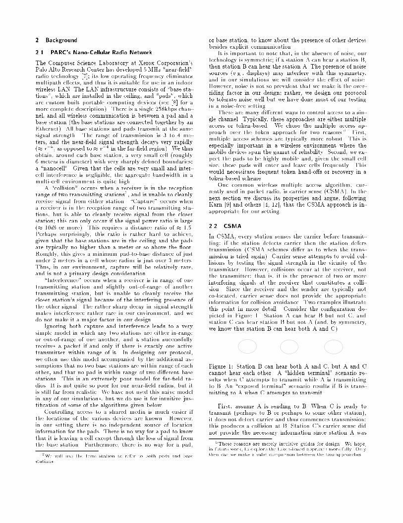
In CSMA� every station senses the carrier before transmit�ting if the station detects carrier then the station deferstransmission CSMA schemes dier as to when the trans�mission is tried again�� Carrier sense attempts to avoid col�lisions by testing the signal strength in the vicinity of thetransmitter� However� collisions occur at the receiver� notthe transmitter that is� it is the presence of two or moreinterfering signals at the receiver that constitutes a colli�sion� Since the receiver and the sender are typically notco�located� carrier sense does not provide the appropriateinformation for collision avoidance� Two examples illustratethis point in more detail� Consider the con�guration de�picted in Figure �� Station A can hear B but not C� andstation C can hear station B but not A and� by symmetry�we know that station B can hear both A and C��
Figure �� Station B can hear both A and C� but A and Ccannot hear each other� A �hidden terminal� scenario re�sults when C attempts to transmit while A is transmittingto B� An �exposed terminal� scenario results if B is trans�mitting to A when C attempts to transmit�
First� assume A is sending to B� When C is ready totransmit perhaps to B or perhaps to some other station��it does not detect carrier and thus commences transmission this produces a collision at B� Station C�s carrier sense didnot provide the necessary information since station A was
�These reasons are merely intuitive guides for design� We hope�in future work� to explore the token�based approach more fully� Onlythen can we make a valid comparison between the two approaches�
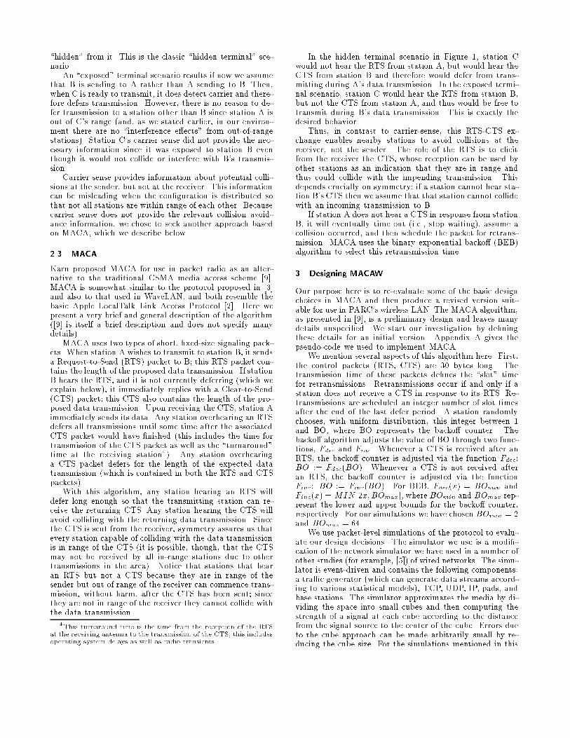
�hidden� from it� This is the classic �hidden terminal� sce�nario�
An �exposed� terminal scenario results if now we assumethat B is sending to A rather than A sending to B� Then�when C is ready to transmit� it does detect carrier and there�fore defers transmission� However� there is no reason to de�fer transmission to a station other than B since station A isout of C�s range and� as we stated earlier� in our environ�ment there are no �interference eects� from out�of�rangestations�� Station C�s carrier sense did not provide the nec�essary information since it was exposed to station B eventhough it would not collide or interfere with B�s transmis�sion�
Carrier sense provides information about potential colli�sions at the sender� but not at the receiver� This informationcan be misleading when the con�guration is distributed sothat not all stations are within range of each other� Becausecarrier sense does not provide the relevant collision avoid�ance information� we chose to seek another approach basedon MACA� which we describe below�
��� MACA
Karn proposed MACA for use in packet radio as an alter�native to the traditional CSMA media access scheme ����MACA is somewhat similar to the protocol proposed in ���and also to that used in WaveLAN� and both resemble thebasic Apple LocalTalk Link Access Protocol ���� Here wepresent a very brief and general description of the algorithm��� is itself a brief description and does not specify manydetails��
MACA uses two types of short� �xed�size signaling pack�ets� When station A wishes to transmit to station B� it sendsa Request�to�Send RTS� packet to B this RTS packet con�tains the length of the proposed data transmission� If stationB hears the RTS� and it is not currently deferring which weexplain below�� it immediately replies with a Clear�to�SendCTS� packet this CTS also contains the length of the pro�posed data transmission� Upon receiving the CTS� station Aimmediately sends its data� Any station overhearing an RTSdefers all transmissions until some time after the associatedCTS packet would have �nished this includes the time fortransmission of the CTS packet as well as the �turnaround�time at the receiving station��� Any station overhearinga CTS packet defers for the length of the expected datatransmission which is contained in both the RTS and CTSpackets��
With this algorithm� any station hearing an RTS willdefer long enough so that the transmitting station can re�ceive the returning CTS� Any station hearing the CTS willavoid colliding with the returning data transmission� Sincethe CTS is sent from the receiver� symmetry assures us thatevery station capable of colliding with the data transmissionis in range of the CTS it is possible� though� that the CTSmay not be received by all in�range stations due to othertransmissions in the area�� Notice that stations that hearan RTS but not a CTS because they are in range of thesender but out of range of the receiver can commence trans�mission� without harm� after the CTS has been sent sincethey are not in range of the receiver they cannot collide withthe data transmission�
�This turnaround time is the time from the reception of the RTSat the receiving antenna to the transmission of the CTS� this includesoperating system delays as well as radio transients�
In the hidden terminal scenario in Figure �� station Cwould not hear the RTS from station A� but would hear theCTS from station B and therefore would defer from trans�mitting during A�s data transmission� In the exposed termi�nal scenario� station C would hear the RTS from station B�but not the CTS from station A� and thus would be free totransmit during B�s data transmission� This is exactly thedesired behavior�
Thus� in contrast to carrier�sense� this RTS�CTS ex�change enables nearby stations to avoid collisions at thereceiver� not the sender� The role of the RTS is to elicitfrom the receiver the CTS� whose reception can be used byother stations as an indication that they are in range andthus could collide with the impending transmission� Thisdepends crucially on symmetry if a station cannot hear sta�tion B�s CTS then we assume that that station cannot collidewith an incoming transmission to B�
If station A does not hear a CTS in response from stationB� it will eventually time out i�e�� stop waiting�� assume acollision occurred� and then schedule the packet for retrans�mission� MACA uses the binary exponential backo BEB�algorithm to select this retransmission time�
� Designing MACAW
Our purpose here is to re�evaluate some of the basic designchoices in MACA and then produce a revised version suit�able for use in PARC�s wireless LAN� The MACA algorithm�as presented in ���� is a preliminary design and leaves manydetails unspeci�ed� We start our investigation by de�ningthese details for an initial version� Appendix A gives thepseudo�code we used to implement MACA�
We mention several aspects of this algorithm here� First�the control packets RTS� CTS� are �� bytes long� Thetransmission time of these packets de�nes the �slot� timefor retransmissions� Retransmissions occur if and only if astation does not receive a CTS in response to its RTS� Re�transmissions are scheduled an integer number of slot timesafter the end of the last defer period� A station randomlychooses� with uniform distribution� this integer between �and BO� where BO represents the backo counter� Thebacko algorithm adjusts the value of BO through two func�tions� Fdec and Finc� Whenever a CTS is received after anRTS� the backo counter is adjusted via the function Fdec�BO �� FdecBO�� Whenever a CTS is not received afteran RTS� the backo counter is adjusted via the functionFinc� BO �� FincBO�� For BEB� Fdecx� � BOmin andFincx� �MIN ��x�BOmax�� where BOmin and BOmax rep�resent the lower and upper bounds for the backo counter�respectively� For our simulations we have chosen BOmin � �and BOmax � ���
We use packet�level simulations of the protocol to evalu�ate our design decisions� The simulator we use is a modi��cation of the network simulator we have used in a number ofother studies for example� ���� of wired networks� The simu�lator is event�driven and contains the following components�a tra�c generator which can generate data streams accord�ing to various statistical models�� TCP� UDP� IP� pads� andbase stations� The simulator approximates the media by di�viding the space into small cubes and then computing thestrength of a signal at each cube according to the distancefrom the signal source to the center of the cube� Errors dueto the cube approach can be made arbitrarily small by re�ducing the cube size� For the simulations mentioned in this
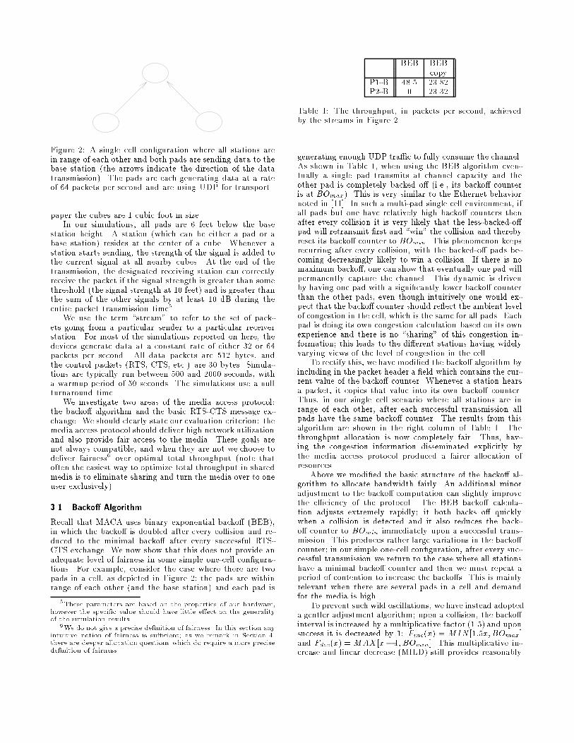
Figure �� A single cell con�guration where all stations arein range of each other and both pads are sending data to thebase station the arrows indicate the direction of the datatransmission�� The pads are each generating data at a rateof �� packets per second and are using UDP for transport�
paper the cubes are � cubic foot in size�In our simulations� all pads are � feet below the base
station height� A station which can be either a pad or abase station� resides at the center of a cube� Whenever astation starts sending� the strength of the signal is added tothe current signal at all nearby cubes� At the end of thetransmission� the designated receiving station can correctlyreceive the packet if the signal strength is greater than somethreshold the signal strength at �� feet� and is greater thanthe sum of the other signals by at least �� dB during theentire packet transmission time��
We use the term �stream� to refer to the set of pack�ets going from a particular sender to a particular receiverstation� For most of the simulations reported on here� thedevices generate data at a constant rate of either �� or ��packets per second� All data packets are ��� bytes� andthe control packets RTS� CTS� etc�� are �� bytes� Simula�tions are typically run between ��� and ���� seconds� witha warmup period of �� seconds� The simulations use a nullturnaround time�
We investigate two areas of the media access protocol�the backo algorithm and the basic RTS�CTS message ex�change� We should clearly state our evaluation criterion� themedia access protocol should deliver high network utilizationand also provide fair access to the media� These goals arenot always compatible� and when they are not we choose todeliver fairness� over optimal total throughput note thatoften the easiest way to optimize total throughput in sharedmedia is to eliminate sharing and turn the media over to oneuser exclusively��
��� Backo� Algorithm
Recall that MACA uses binary exponential backo BEB��in which the backo is doubled after every collision and re�duced to the minimal backo after every successful RTS�CTS exchange� We now show that this does not provide anadequate level of fairness in some simple one�cell con�gura�tions� For example� consider the case where there are twopads in a cell� as depicted in Figure � the pads are withinrange of each other and the base station� and each pad is
�These parameters are based on the properties of our hardware�however the speci�c value should have little e�ect on the generalityof the simulation results�
�We do not give a precise de�nition of fairness� In this section anyintuitive notion of fairness is su�cient� as we remark in Section ��there are deeper allocation questions which do require a more precisede�nition of fairness�
BEB BEBcopy
P��B ���� �����P��B � �����
Table �� The throughput� in packets per second� achievedby the streams in Figure ��
generating enough UDP tra�c to fully consume the channel�As shown in Table �� when using the BEB algorithm even�tually a single pad transmits at channel capacity and theother pad is completely backed o i�e�� its backo counteris at BOmax�� This is very similar to the Ethernet behaviornoted in ����� In such a multi�pad single cell environment� ifall pads but one have relatively high backo counters thenafter every collision it is very likely that the less�backed�opad will retransmit �rst and �win� the collision and therebyreset its backo counter to BOmin� This phenomenon keepsrecurring after every collision� with the backed�o pads be�coming decreasingly likely to win a collision� If there is nomaximum backo� one can show that eventually one pad willpermanently capture the channel� This dynamic is drivenby having one pad with a signi�cantly lower backo counterthan the other pads� even though intuitively one would ex�pect that the backo counter should re�ect the ambient levelof congestion in the cell� which is the same for all pads� Eachpad is doing its own congestion calculation based on its ownexperience and there is no �sharing� of this congestion in�formation this leads to the dierent stations having widelyvarying views of the level of congestion in the cell�
To rectify this� we have modi�ed the backo algorithm byincluding in the packet header a �eld which contains the cur�rent value of the backo counter� Whenever a station hearsa packet� it copies that value into its own backo counter�Thus� in our single cell scenario where all stations are inrange of each other� after each successful transmission allpads have the same backo counter� The results from thisalgorithm are shown in the right column of Table �� Thethroughput allocation is now completely fair� Thus� hav�ing the congestion information disseminated explicitly bythe media access protocol produced a fairer allocation ofresources�
Above we modi�ed the basic structure of the backo al�gorithm to allocate bandwidth fairly� An additional minoradjustment to the backo computation can slightly improvethe e�ciency of the protocol� The BEB backo calcula�tion adjusts extremely rapidly it both backs o quicklywhen a collision is detected and it also reduces the back�o counter to BOmin immediately upon a successful trans�mission� This produces rather large variations in the backocounter in our simple one�cell con�guration� after every suc�cessful transmission we return to the case where all stationshave a minimal backo counter and then we must repeat aperiod of contention to increase the backos� This is mainlyrelevant when there are several pads in a cell and demandfor the media is high�
To prevent such wild oscillations� we have instead adopteda gentler adjustment algorithm upon a collision� the backointerval is increased by a multiplicative factor ���� and uponsuccess it is decreased by �� Fincx� � MIN ����x�BOmax�and Fdecx� �MAX�x� ��BOmin�� This multiplicative in�crease and linear decrease MILD� still provides reasonably
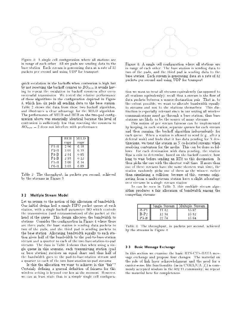
Figure �� A single cell con�guration where all stations arein range of each other� All six pads are sending data to thebase station� Each stream is generating data at a rate of ��packets per second and using UDP for transport�
quick escalation in the backos when contention is high butby not resetting the backo counter to BOmin it avoids hav�ing to repeat the escalation in backo counters after everysuccessful tranmission� We tested the relative performanceof these algorithms in the con�guration depicted in Figure�� which has six pads all sending data to the base station�Table � shows the data from these two backo algorithm�and illustrates a clear advantage for the MILD algorithm�The performance of MILD and BEB on the two�pad con�g�uration above was essentially identical because the level ofcontention is su�ciently low that resetting the counters toBOmin � � does not interfere with performance�
BEB MILDcopy copy
P��B ���� ����P��B ���� ����P��B ���� ����P��B ���� ����P��B ���� ����P��B ���� ����
Table �� The throughput� in packets per second� achievedby the streams in Figure ��
��� Multiple Stream Model
Let us return to the notion of fair allocation of bandwidth�Our initial design had a single FIFO packet queue at eachstation� with a single backo parameter BO which controlsthe transmission and retransmissions� of the packet at thehead of the queue� This design allocates the bandwidth tostations� Consider the con�guration in Figure � where thereare three pads the base station is sending data packets totwo of the pads� and the third pad is sending packets tothe base station� Allocating bandwidth equally to each sta�tion gives half of the bandwidth to the pad�to�base�stationstream and a quarter to each of the two base�station�to�padstreams� The data in Table � shows that when using a sin�gle queue in this scenario� each transmitting station pador base station� receives an equal share and thus half ofthe bandwidth goes to the pad�to�base�station stream anda quarter to each of the two base�station�to�pad streams�
Is this the allocation we want to achieve is this �fair��Certainly de�ning a general de�nition of fairness for thiswireless setting is beyond our ken at the moment� However�we can at least state that in a simple single cell con�gura�
Figure �� A single cell con�guration where all stations arein range of each other� The base station is sending data totwo of the pads� and the third pad is sending data to thebase station� Each stream is generating data at a rate of ��packets per second and using UDP for transport�
tion we want to treat all streams equivalently as opposed toall stations equivalently� recall that a stream is the �ow ofdata packets between a source�destination pair� That is� tothe extent possible� we want to allocate bandwidth equallyto streams and not to the stations themselves� This dis�tinction is especially relevant since in our setting all wirelesscommunications must go through a base station� thus basestations are likely to be the source of many streams�
This notion of per stream fairness can be implementedby keeping� in each station� separate queues for each streamand then running the backo algorithm independently foreach queue� When a station is allowed to send e�g�� after adeferral wait� and �nds that it has data pending for N des�tinations� we treat the station as N co�located streams whenresolving contention for the media� This can be done as fol�lows� For each destination with data pending� the station�ips a coin to determine� based on the backo counter� howlong to wait before sending an RTS to this destination� Itthen picks the one with the shortest wait time� If more thanone of these streams have the same shortest wait time� thestation randomly picks one of them as the winner� ratherthan simulating a collision because of this� streams origi�nating from a multi�stream station have a slight advantageover streams in a single stream station�
As can be seen in Table �� this multiple stream algo�rithm produces a fair allocation of bandwidth among thecompeting streams�
Single Stream Multiple StreamB�P� ����� �����B�P� ����� �����P��B ����� �����
Table �� The throughput� in packets per second� achievedby the streams in Figure ��
��� Basic Message Exchange
In this section we examine the basic RTS�CTS�DATA mes�sage exchange and propose four changes� The material onthe role of link layer acknowledgment and the need for acarrier�sense like functionality as in CSMA�CA ���� is com�monly accepted wisdom in the ������ community we repeatthe material here for completeness�

����� ACK
Many of the applications used on mobile devices� such aselectronic mail� require reliable delivery of data� At thetransport layer these applications use TCP as opposed toUDP which was used in the previous simulations� to pro�vide that reliability� In MACA� when data packets suera collision� or are corrupted by noise� the error has to berecovered by the transport layer� This necessitates a sig�ni�cant wait� as many current TCP implementations havea minimum timeout period of ���sec� which was chosen toaccommodate both local and long haul data transmissions�
In contrast� recovery at the link�layer can be much fasterbecause the timeout periods can be tailored to �t the shorttime scales of the media� Thus we have amended the basicRTS�CTS�DATA exchange to include an acknowledgementpacket� ACK� that is returned from the receiver to the senderimmediately upon completion of data reception� If the ACKis not received by the sender� then the data packet is sched�uled for retransmission� If the data packet had indeed beencorrectly received but the ACK packet was not� then whenthe RTS for the retransmission is sent� the receiver returnsthe associated ACK instead of a CTS� The sender increasesits backo if� after sending an RTS� no CTS or ACK arrivesbefore it times out the sender decreases its backo whenthe ACK is received� The backo counter is not changed ifthere is a successful RTS�CTS exchange but the ACK doesnot arrive�
We have simulated the eects of intermittent noise ona single pad�to�base�station stream� Intermittent noise ismodeled as a given probability that each packet regard�less of size� is not received cleanly at its intended desti�nation� Table � shows the resulting throughput� For theoriginal RTS�CTS�DATA exchange� the dramatic decreasein throughput as the noise level increases is due to the slowrecovery at the TCP layer� The decrease in throughputwhen the ACK is included is much less severe� The over�head due to the inclusion of the ACK packet is only about�� ����� PPS vs� ����� in the no noise case�� and whenthe loss rate is only � packet in ���� the two algorithms giveessentially identical results� Given that intermittent noise islikely to be present� and that it can have such a deleteriouseect on the network throughput� we have decided that theaugmented RTS�CTS�DATA�ACK exchange should be usedfor all reliable data transmissions�
Error Rate RTS�CTS�DATA RTS�CTS�DATA�ACK� ����� �����
����� ����� ��������� ����� �������� ���� ����
Table �� The throughput� in packets per second� achieved bya single TCP data stream between a pad and a base stationin the presence of noise�
����� DS
In the original analysis of the exposed terminal con�gurationFigure ��� we argued that the exposed terminal C shouldbe free to transmit because even though it is in range of thesender B� it is out of range of the receiver A� and the receiver
Figure �� A two cell con�guration where both pads are inrange of their respective base stations and also in range ofeach other� The pads are sending data to their base stations�and each stream is generating data at a rate of �� packetsper second and using UDP for transport�
is the only station that matters� However� C�s transmissioncan bene�t only if C can hear a returning CTS� When B istransmitting� C is unable to hear any replies and thus initi�ating a transfer is useless�� Moreover� when C does initiateand does not get any response� its backo counter increasesrapidly� With simple uni�directional transmissions the onlyrelevant congestion is at the receiver however� with our bi�directional RST�CTS�DATA message exchange� congestionat both ends of the transmission is relevant�
We conclude from this line of reasoning that C shoulddefer transmission while B is transmitting data� Note thatbecause C has only heard the RTS and not the CTS� stationC cannot tell if the RTS�CTS exchange was a success andso does not know if B is indeed transmitting data�
There are two approaches to this problem� One can usecarrier�sense to avoid sending useless RTS�s� A station mustdefer transmission until one slot time after it detects nocarrier the inclusion of a single slot time of clear air is toensure that exposed terminals do not clobber the returningACK�� This is essentially the CSMA�CA protocol ���� Wechose a slightly dierent approach� which does not requirecarrier sensing hardware� Before sending a DATA packet�a station sends a short ���byte Data�Sending packet DS��Every station which overhears this packet will know that theRTS�CTS exchange was successful and that a data transmis�sion is about to occur these overhearing stations defer alltransmissions until after the ACK packet slot has passed�
RTS�CTS�DATA�ACK RTS�CTS�DS�DATA�ACK
P��B� ����� �����P��B� � �����
Table �� The throughput� in packets per second� achievedby the streams in Figure ��
We have examined the performance of this protocol inthe simple two�cell con�guration of Figure �� Here eachpad is an exposed terminal to the other pad�to�base�stationstream� Table � shows the throughput with and without theDS packet� Without the DS packet� one of the pads losesthe �rst contention period and then proceeds to futilely re�transmit this leads to it rapidly increasing its backo whichthen renders it unable to capture the media at all� The keyis that without the DS packet the �losing� pad cannot iden�tify when the next contention period i�e�� the slots after
�We should also note that C�s transmission does not harm thesender B only if the sender does not need to receive a packet after theCTS� Now that we have included the ACK packet after the DATApacket� this assumption no longer holds� If the exposed terminalbegins transmitting after not hearing the CTS� then it is possiblethat its transmission will collide with the ACK returned from A toB�
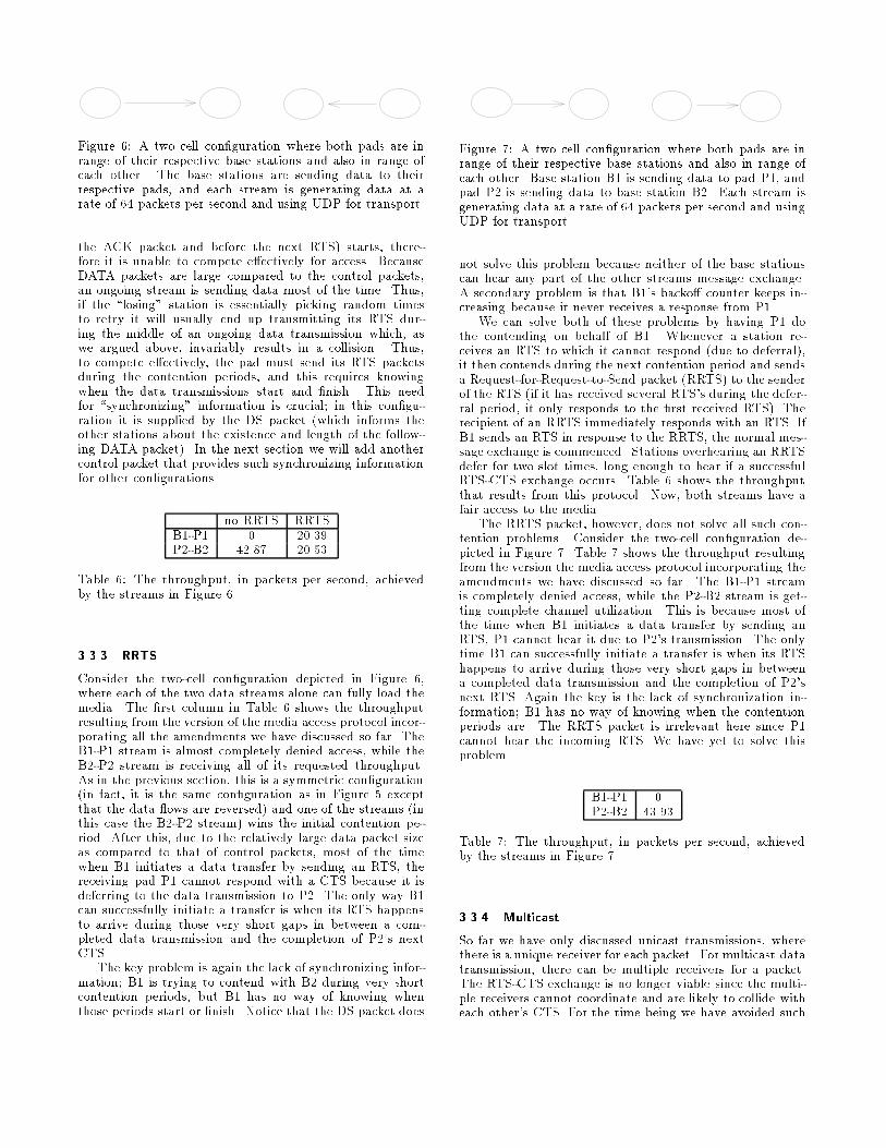
Figure �� A two cell con�guration where both pads are inrange of their respective base stations and also in range ofeach other� The base stations are sending data to theirrespective pads� and each stream is generating data at arate of �� packets per second and using UDP for transport�
the ACK packet and before the next RTS� starts� there�fore it is unable to compete eectively for access� BecauseDATA packets are large compared to the control packets�an ongoing stream is sending data most of the time� Thus�if the �losing� station is essentially picking random timesto retry it will usually end up transmitting its RTS dur�ing the middle of an ongoing data transmission which� aswe argued above� invariably results in a collision� Thus�to compete eectively� the pad must send its RTS packetsduring the contention periods� and this requires knowingwhen the data transmissions start and �nish� This needfor �synchronizing� information is crucial in this con�gu�ration it is supplied by the DS packet which informs theother stations about the existence and length of the follow�ing DATA packet�� In the next section we will add anothercontrol packet that provides such synchronizing informationfor other con�gurations�
no RRTS RRTSB��P� � �����P��B� ����� �����
Table �� The throughput� in packets per second� achievedby the streams in Figure ��
����� RRTS
Consider the two�cell con�guration depicted in Figure ��where each of the two data streams alone can fully load themedia� The �rst column in Table � shows the throughputresulting from the version of the media access protocol incor�porating all the amendments we have discussed so far� TheB��P� stream is almost completely denied access� while theB��P� stream is receiving all of its requested throughput�As in the previous section� this is a symmetric con�gurationin fact� it is the same con�guration as in Figure � exceptthat the data �ows are reversed� and one of the streams inthis case the B��P� stream� wins the initial contention pe�riod� After this� due to the relatively large data packet sizeas compared to that of control packets� most of the timewhen B� initiates a data transfer by sending an RTS� thereceiving pad P� cannot respond with a CTS because it isdeferring to the data transmission to P�� The only way B�can successfully initiate a transfer is when its RTS happensto arrive during those very short gaps in between a com�pleted data transmission and the completion of P��s nextCTS�
The key problem is again the lack of synchronizing infor�mation B� is trying to contend with B� during very shortcontention periods� but B� has no way of knowing whenthose periods start or �nish� Notice that the DS packet does
Figure �� A two cell con�guration where both pads are inrange of their respective base stations and also in range ofeach other� Base station B� is sending data to pad P�� andpad P� is sending data to base station B�� Each stream isgenerating data at a rate of �� packets per second and usingUDP for transport�
not solve this problem because neither of the base stationscan hear any part of the other streams message exchange�A secondary problem is that B��s backo counter keeps in�creasing because it never receives a response from P��
We can solve both of these problems by having P� dothe contending on behalf of B�� Whenever a station re�ceives an RTS to which it cannot respond due to deferral��it then contends during the next contention period and sendsa Request�for�Request�to�Send packet RRTS� to the senderof the RTS if it has received several RTS�s during the defer�ral period� it only responds to the �rst received RTS�� Therecipient of an RRTS immediately responds with an RTS� IfB� sends an RTS in response to the RRTS� the normal mes�sage exchange is commenced� Stations overhearing an RRTSdefer for two slot times� long enough to hear if a successfulRTS�CTS exchange occurs� Table � shows the throughputthat results from this protocol� Now� both streams have afair access to the media�
The RRTS packet� however� does not solve all such con�tention problems� Consider the two�cell con�guration de�picted in Figure �� Table � shows the throughput resultingfrom the version the media access protocol incorporating theamendments we have discussed so far� The B��P� streamis completely denied access� while the P��B� stream is get�ting complete channel utilization� This is because most ofthe time when B� initiates a data transfer by sending anRTS� P� cannot hear it due to P��s transmission� The onlytime B� can successfully initiate a transfer is when its RTShappens to arrive during those very short gaps in betweena completed data transmission and the completion of P��snext RTS� Again the key is the lack of synchronization in�formation B� has no way of knowing when the contentionperiods are� The RRTS packet is irrelevant here since P�cannot hear the incoming RTS� We have yet to solve thisproblem�
B��P� �P��B� �����
Table �� The throughput� in packets per second� achievedby the streams in Figure ��
����� Multicast
So far we have only discussed unicast transmissions� wherethere is a unique receiver for each packet� For multicast datatransmission� there can be multiple receivers for a packet�The RTS�CTS exchange is no longer viable since the multi�ple receivers cannot coordinate and are likely to collide witheach other�s CTS� For the time being we have avoided such
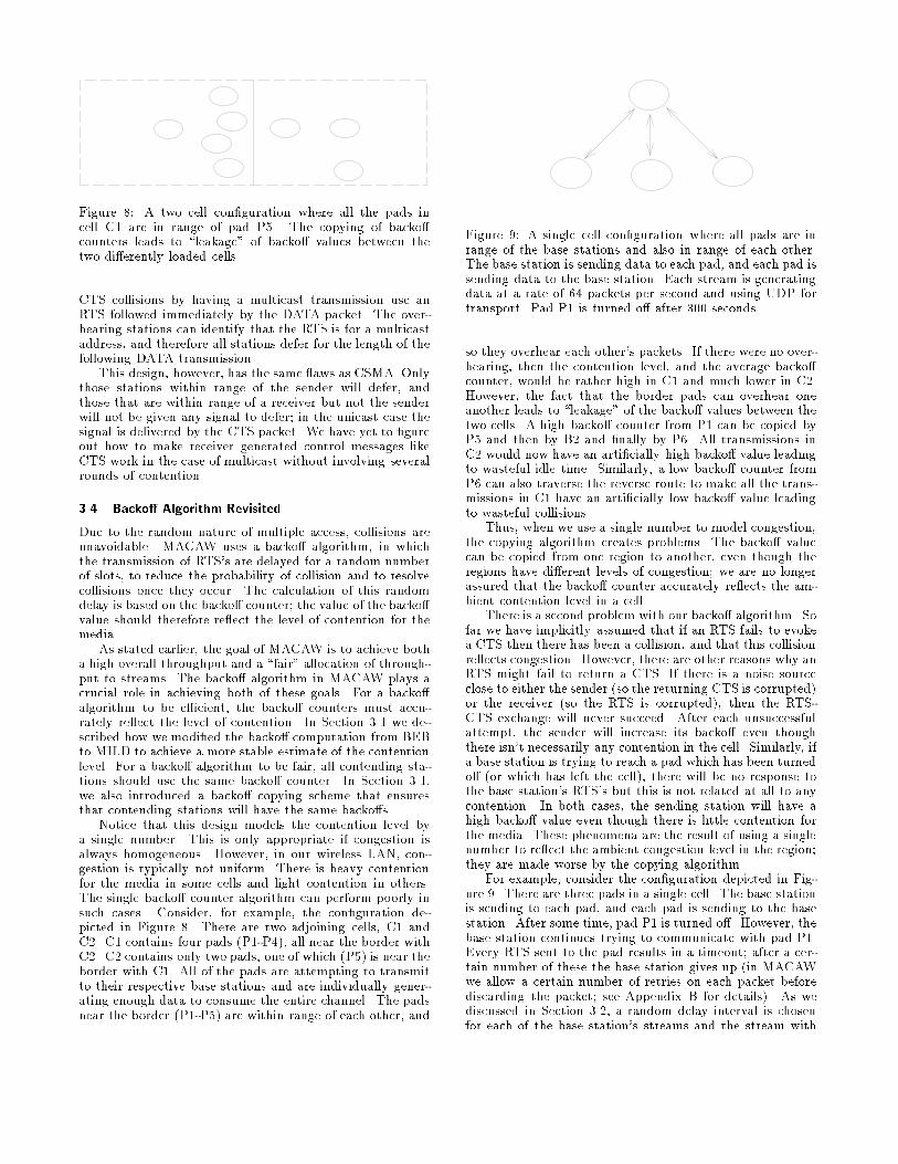
Figure �� A two cell con�guration where all the pads incell C� are in range of pad P�� The copying of backocounters leads to �leakage� of backo values between thetwo dierently loaded cells�
CTS collisions by having a multicast transmission use anRTS followed immediately by the DATA packet� The over�hearing stations can identify that the RTS is for a multicastaddress� and therefore all stations defer for the length of thefollowing DATA transmission�
This design� however� has the same �aws as CSMA� Onlythose stations within range of the sender will defer� andthose that are within range of a receiver but not the senderwill not be given any signal to defer in the unicast case thesignal is delivered by the CTS packet� We have yet to �gureout how to make receiver generated control messages likeCTS work in the case of multicast without involving severalrounds of contention�
��� Backo� Algorithm Revisited
Due to the random nature of multiple access� collisions areunavoidable� MACAW uses a backo algorithm� in whichthe transmission of RTS�s are delayed for a random numberof slots� to reduce the probability of collision and to resolvecollisions once they occur� The calculation of this randomdelay is based on the backo counter the value of the backovalue should therefore re�ect the level of contention for themedia�
As stated earlier� the goal of MACAW is to achieve botha high overall throughput and a �fair� allocation of through�put to streams� The backo algorithm in MACAW plays acrucial role in achieving both of these goals� For a backoalgorithm to be e�cient� the backo counters must accu�rately re�ect the level of contention� In Section ��� we de�scribed how we modi�ed the backo computation from BEBto MILD to achieve a more stable estimate of the contentionlevel� For a backo algorithm to be fair� all contending sta�tions should use the same backo counter� In Section ����we also introduced a backo copying scheme that ensuresthat contending stations will have the same backos�
Notice that this design models the contention level bya single number� This is only appropriate if congestion isalways homogeneous� However� in our wireless LAN� con�gestion is typically not uniform� There is heavy contentionfor the media in some cells and light contention in others�The single backo counter algorithm can perform poorly insuch cases� Consider� for example� the con�guration de�picted in Figure �� There are two adjoining cells� C� andC�� C� contains four pads P��P��� all near the border withC�� C� contains only two pads� one of which P�� is near theborder with C�� All of the pads are attempting to transmitto their respective base stations and are individually gener�ating enough data to consume the entire channel� The padsnear the border P��P�� are within range of each other� and
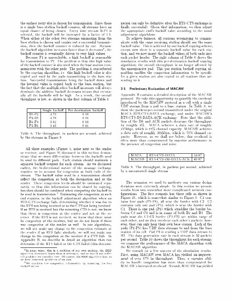
Figure �� A single cell con�guration where all pads are inrange of the base stations and also in range of each other�The base station is sending data to each pad� and each pad issending data to the base station� Each stream is generatingdata at a rate of �� packets per second and using UDP fortransport� Pad P� is turned o after ��� seconds�
so they overhear each other�s packets� If there were no over�hearing� then the contention level� and the average backocounter� would be rather high in C� and much lower in C��However� the fact that the border pads can overhear oneanother leads to �leakage� of the backo values between thetwo cells� A high backo counter from P� can be copied byP� and then by B� and �nally by P�� All transmissions inC� would now have an arti�cially high backo value leadingto wasteful idle time� Similarly� a low backo counter fromP� can also traverse the reverse route to make all the trans�missions in C� have an arti�cially low backo value leadingto wasteful collisions�
Thus� when we use a single number to model congestion�the copying algorithm creates problems� The backo valuecan be copied from one region to another� even though theregions have dierent levels of congestion we are no longerassured that the backo counter accurately re�ects the am�bient contention level in a cell�
There is a second problem with our backo algorithm� Sofar we have implicitly assumed that if an RTS fails to evokea CTS then there has been a collision� and that this collisionre�ects congestion� However� there are other reasons why anRTS might fail to return a CTS� If there is a noise sourceclose to either the sender so the returning CTS is corrupted�or the receiver so the RTS is corrupted�� then the RTS�CTS exchange will never succeed� After each unsuccessfulattempt� the sender will increase its backo even thoughthere isn�t necessarily any contention in the cell� Similarly� ifa base station is trying to reach a pad which has been turnedo or which has left the cell�� there will be no response tothe base station�s RTS�s but this is not related at all to anycontention� In both cases� the sending station will have ahigh backo value even though there is little contention forthe media� These phenomena are the result of using a singlenumber to re�ect the ambient congestion level in the region they are made worse by the copying algorithm�
For example� consider the con�guration depicted in Fig�ure �� There are three pads in a single cell� The base stationis sending to each pad� and each pad is sending to the basestation� After some time� pad P� is turned o� However� thebase station continues trying to communicate with pad P��Every RTS sent to the pad results in a timeout after a cer�tain number of these the base station gives up in MACAWwe allow a certain number of retries on each packet beforediscarding the packet see Appendix B for details�� As wediscussed in Section ���� a random delay interval is chosenfor each of the base station�s streams and the stream with
the earliest retry slot is chosen for transmission� Since thereis a single base station backo counter� all streams have anequal chance of being chosen� Every time stream B�P� isselected� the backo will be increased by a factor of ����When either of the other two streams emanating from thebase station is chosen and carries out a successful transmis�sion� then the backo counter is reduced by one� Becausethe backo algorithm increases faster than it decreases�� thebacko counter is eventually driven to very high values�
Because P� is unreachable� a high backo is reasonablefor transmission to P�� The problem is that this high valueof the backo counter is also used when the base station com�municates with the other pads� The problem is exacerbatedby the copying algorithm� i�e� this high backo value is alsocopied and used by the pads transmitting to the base sta�tion� Successful transmissions bring the backo down andthe lowered value is copied back to the base station� butthe fact that the multiplicative backo increases will alwaysdominate the additive backo decreases means that eventu�ally all the backos will be high� As a result� the overallthoughput is low� as shown in the �rst column of Table ��
Single backo Per�destination backoB��P� ���� ����P��B� ���� ����B��P� ���� ����P��B� ���� ����
Table �� The throughput� in packets per second� achievedby the streams in Figure ��
All three examples Figure �� noise next to the senderor receiver� and Figure �� discussed in this section demon�strate that we must dierentiate between the backos usedto send to dierent pads� Each station should maintain aseparate backo counter for each stream� As we discussedearlier� the bi�directional nature of the message exchangerequires us to account for congestion at both ends of thestream� The backo value used in a transmission shouldre�ect the congestion at both the destination and at thesender� These congestion levels should be estimated sepa�rately� so that this information can be shared by copying�but then should be combined when computing the backo tobe used in transmission�� Estimating the congestion at eachend requires� in the backo adjustment algorithm when anRTS�CTS exchange fails� determining whether it was due tothe RTS not being received or to the CTS not being received�If an RTS is received but the returning CTS is not� we knowthat there is congestion at the sender and not at the re�ceiver� If the RTS is not received� we know that there mustbe congestion at the receiver� but we do not know if therewas congestion at the sender as well� In our algorithms�we will not make any change to the congestion estimate atthe sender if an RTS fails similarly� we will not make anychange to the congestion at the receiver if a CTS fails� InAppendix B� we describe in detail an algorithm that candetermine if the RTS failed or the CTS failed this determi�
�In some sense� this is a problem of our own making� the BEBalgorithm decreases faster than it increases� and so would not su�erthe problem we describe here� Of course� the BEB algorithm has� aswe have observed� problems of its own�
�We combine the congestion information by summing the twobacko� values�
nation can only be de�nitive after the RTS�CTS exchange is�nally successful�� Given that information� we then adjustthe appropriate end�s backo value according to the usualadjustment algorithms�
To achieve fairness� all stations attempting to commu�nicate with the same receiving station should use the samebacko value� This is achieved by our backo copying scheme�except now there is a separate backo value for each sta�tion� and we now insert the backo values of both ends intoeach packet header� The right column of Table � shows thesimulation results with this per�destination backo copyingalgorithm the overall throughput is no longer aected bythe unresponsive pad� This per station backo copying al�gorithm enables the congestion information to be speci�cfor a given station yet also copied to all stations that aresending to it�
��� Preliminary Evaluation of MACAW
Appendix B contains a detailed description of the MACAWprotocol� We take this opportunity to quantify the overheadintroduced by the MACAW protocol in a cell with a singleUDP stream from a pad to a base station� In Table �� weshow the packets�per�second transmitted under the originalMACA RTS�CTS�DATA exchange� and under MACAW�sRTS�CTS�DS�DATA�ACK exchange� Note that the addi�tion of the DS and ACK packets decrease the throughputby roughly ��� MACA achieves a data rate of roughly���kbps� which is ��� channel capacity� MACAW achievesa data rate of roughly ���kbps� which is ��� channel ca�pacity� However� as we shall see below� this overhead isoften more than compensated by superior performance inthe presence of congestion and noise�
MACA RTS�CTS�DATA �����MACAW RTS�CTS�DS�DATA�ACK �����
Table �� The throughput� in packets per second� achievedby a uncontested single stream�
The scenarios we used to motivate our various designdecisions were extremely simple� In this section we presentresults from two somewhat more complicated network con��gurations� The �rst scenario has three cells as shown inFigure ��� which is somewhat similar to Figure �� C� con�tains four pads P��P��� all near the border with C�� C�contains only one pad P��� which is near the border withC�� There is one pad P�� which straddles the border be�tween C� and C� and is in range of both B� and B�� Thepads near the C��C� border P��P�� are within range ofeach other� and so they overhear each other�s packets how�ever� they can only hear their own base station� Each of thepads P��P�� has UDP data streams to and from the basestation of its cell� Pad P� is sending a UDP data stream toB�� The data generation rate in each stream is �� packetsper second� Table �� shows the throughput for each stream we compare the performance of the MACA algorithm withthe MACAW algorithm�
We remark on a few aspects of the simulation results�First� using MACAW over MACA has yielded an improve�ment of over ��� in throughput� Thus� a superior abil�ity to handle congestion has more than compensated forMACAW�s increased overhead� Second� MACAWhas yielded
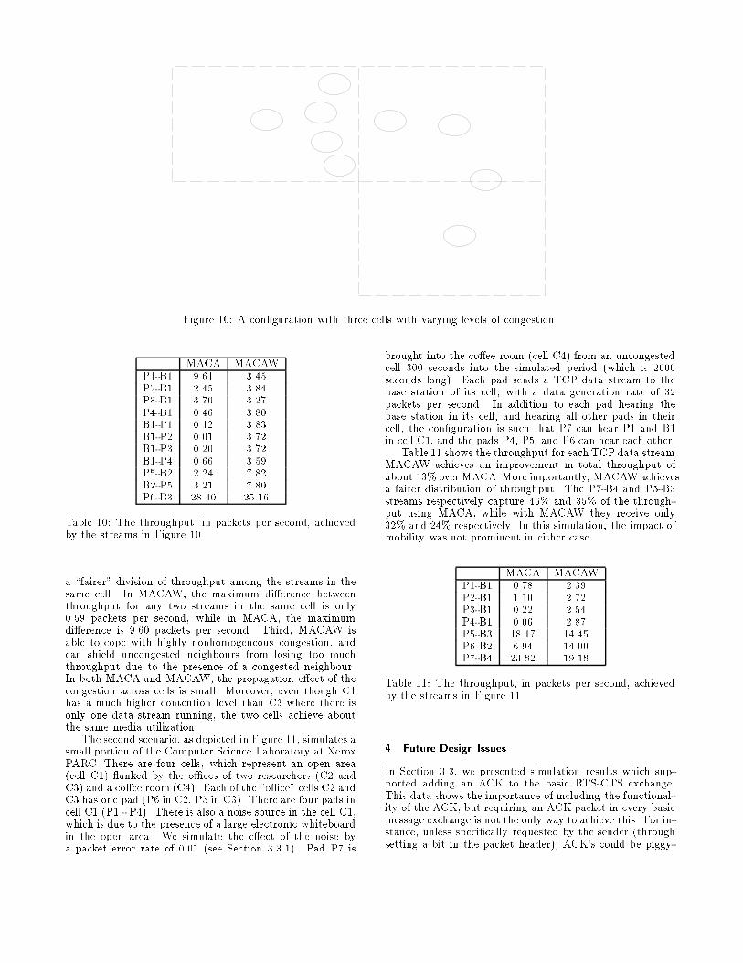
Figure ��� A con�guration with three cells with varying levels of congestion�
MACA MACAWP��B� ���� ����P��B� ���� ����P��B� ���� ����P��B� ���� ����B��P� ���� ����B��P� ���� ����B��P� ���� ����B��P� ���� ����P��B� ���� ����B��P� ���� ����P��B� ����� �����
Table ��� The throughput� in packets per second� achievedby the streams in Figure ���
a �fairer� division of throughput among the streams in thesame cell� In MACAW� the maximum dierence betweenthroughput for any two streams in the same cell is only���� packets per second� while in MACA� the maximumdierence is ���� packets per second� Third� MACAW isable to cope with highly nonhomogeneous congestion� andcan shield uncongested neighbours from losing too muchthroughput due to the presence of a congested neighbour�In both MACA and MACAW� the propagation eect of thecongestion across cells is small� Moreover� even though C�has a much higher contention level than C� where there isonly one data stream running� the two cells achieve aboutthe same media utilization�
The second scenario� as depicted in Figure ��� simulates asmall portion of the Computer Science Laboratory at XeroxPARC� There are four cells� which represent an open areacell C�� �anked by the o�ces of two researchers C� andC�� and a coee room C��� Each of the �o�ce� cells C� andC� has one pad P� in C�� P� in C��� There are four pads incell C� P� � P��� There is also a noise source in the cell C��which is due to the presence of a large electronic whiteboardin the open area� We simulate the eect of the noise bya packet error rate of ���� see Section ������� Pad P� is
brought into the coee room cell C�� from an uncongestedcell ��� seconds into the simulated period which is ����seconds long�� Each pad sends a TCP data stream to thebase station of its cell� with a data generation rate of ��packets per second� In addition to each pad hearing thebase station in its cell� and hearing all other pads in theircell� the con�guration is such that P� can hear P� and B�in cell C�� and the pads P�� P�� and P� can hear each other�
Table �� shows the throughput for each TCP data stream�MACAW achieves an improvement in total throughput ofabout ��� over MACA�More importantly� MACAW achievesa fairer distribution of throughput� The P��B� and P��B�streams respectively capture ��� and ��� of the through�put using MACA� while with MACAW they receive only��� and ��� respectively� In this simulation� the impact ofmobility was not prominent in either case�
MACA MACAWP��B� ���� ����P��B� ���� ����P��B� ���� ����P��B� ���� ����P��B� ����� �����P��B� ���� �����P��B� ����� �����
Table ��� The throughput� in packets per second� achievedby the streams in Figure ���
� Future Design Issues
In Section ���� we presented simulation results which sup�ported adding an ACK to the basic RTS�CTS exchange�This data shows the importance of including the functional�ity of the ACK� but requiring an ACK packet in every basicmessage exchange is not the only way to achieve this� For in�stance� unless speci�cally requested by the sender throughsetting a bit in the packet header�� ACK�s could be piggy�
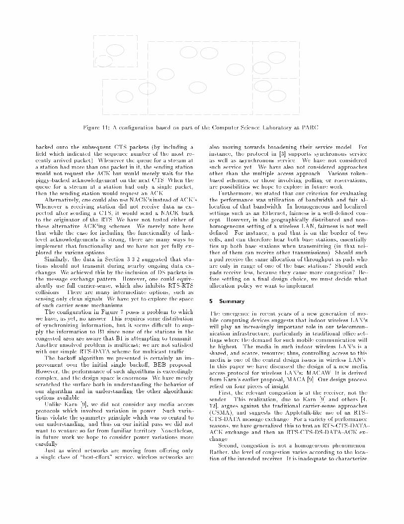
Figure ��� A con�guration based on part of the Computer Science Laboratory at PARC�
backed onto the subsequent CTS packets by including a�eld which indicated the sequence number of the most re�cently arrived packet�� Whenever the queue for a stream ata station had more than one packet in it� the sending stationwould not request the ACK but would merely wait for thepiggy�backed acknowledgement on the next CTS� When thequeue for a stream at a station had only a single packet�then the sending station would request an ACK�
Alternatively� one could also use NACK�s instead of ACK�s�Whenever a receiving station did not receive data as ex�pected after sending a CTS� it would send a NACK backto the originator of the RTS� We have not tested either ofthese alternative ACK�ing schemes� We merely note herethat while the case for including the functionality of link�level acknowledgements is strong� there are many ways toimplement that functionality and we have not yet fully ex�plored the various options�
Similarly� the data in Section ����� suggested that sta�tions should not transmit during nearby ongoing data ex�changes� We achieved this by the inclusion of DS packets inthe message exchange pattern� However� one could equiv�alently use full carrier�sense� which also inhibits RTS�RTScollisions� There are many intermediate options� such assensing only clean signals� We have yet to explore the spaceof such carrier sense mechanisms�
The con�guration in Figure � poses a problem to whichwe have� as yet� no answer� This requires some distributionof synchronizing information� but it seems di�cult to sup�ply the information to B� since none of the stations in thecongested area are aware that B� is attempting to transmit�Another unsolved problem is multicast we are not satis�edwith our simple RTS�DATA scheme for multicast tra�c�
The backo algorithm we presented is certainly an im�provement over the initial single backo� BEB proposal�However� the performance of such algorithms is exceedinglycomplex� and the design space is enormous� We have merelyscratched the surface both in understanding the behavior ofour algorithm and in understanding the other algorithmicoptions available�
Unlike Karn ���� we did not consider any media accessprotocols which involved variation in power� Such varia�tions violate the symmetry principle which was so central toour understanding� and thus on our initial pass we did notwant to venture so far from familiar territory� Nonetheless�in future work we hope to consider power variations morecarefully�
Just as wired networks are moving from oering onlya single class of �best�eort� service� wireless networks are
also moving towards broadening their service model� Forinstance� the protocol in ��� supports synchronous serviceas well as asynchronous service� We have not consideredsuch service yet� We have also not considered approachesother than the multiple access approach� Various token�based schemes� or those involving polling or reservations�are possibilities we hope to explore in future work�
Furthermore� we stated that our criterion for evaluatingthe performance was utilization of bandwidth and fair al�location of that bandwidth� In homogeneous and localizedsettings such as an Ethernet� fairness is a well�de�ned con�cept� However� in the geographically distributed and non�homogeneous setting of a wireless LAN� fairness is not wellde�ned� For instance� a pad that is on the border of twocells� and can therefore hear both base stations� essentiallyties up both base stations when transmitting in that nei�ther of them can receive other transmissions�� Should sucha pad receive the same allocation of throughput as pads whoare only in range of one of the base stations� Should suchpads receive less� because they cause more congestion� Be�fore settling on a �nal design choice� we must decide whatallocation policy we want to implement�
� Summary
The emergence in recent years of a new generation of mo�bile computing devices suggests that indoor wireless LAN�swill play an increasingly important role in our telecommu�nication infrastructure� particularly in traditional o�ce set�tings where the demand for such mobile communication willbe highest� The media in such indoor wireless LAN�s is ashared� and scarce� resource thus� controlling access to thismedia is one of the central design issues in wireless LAN�s�In this paper we have discussed the design of a new mediaaccess protocol for wireless LAN�s� MACAW� It is derivedfrom Karn�s earlier proposal� MACA ���� Our design processrelied on four pieces of insight�
First� the relevant congestion is at the receiver� not thesender� This realization� due to Karn ��� and others ������� argues against the traditional carrier�sense approachesCSMA�� and suggests the Appletalk�like use of an RTS�CTS�DATAmessage exchange� For a variety of performancereasons� we have generalized this to �rst an RTS�CTS�DATA�ACK exchange and then an RTS�CTS�DS�DATA�ACK ex�change�
Second� congestion is not a homogeneous phenomenon�Rather� the level of congestion varies according to the loca�tion of the intended receiver� It is inadequate to characterize
congestion by a single backo parameter� We instead intro�duced separate backo parameters for each stream� and thenfor each end of the stream� Care was taken to identify whichend of the stream was experiencing collisions�
Third� learning about congestion levels should be a col�lective enterprise� When each station must rely on its owndirect experience in estimating congestion� often chance leadsto highly asymmmetric views of a homogeneous environ�ment� To rectify this� we introduced the notion of �copying�the backo parameters from overheard packets� This ideacould be relevant to not only wireless networks but also toEthernets and other shared media�
Fourth� the media access protocol should propagate syn�chronization information about contention periods� so thatall devices can contend eectively� The DS packet is one ex�ample of providing the synchronizing information� Note thatthis observation implies that contention for access should notjust be initiated by the sender of data� In cases where thecongestion is mainly at the receiver�s location� the sendercannot contend eectively since it cannot know when thedata transmissions are over� We introduced the RRTS packetso that the receiving end can contend for bandwidth whenit is in the presence of congestion� This packet also allowscongestion information to be sent even when data was notbeing communicated�
These various changes have signi�cantly improved theperformance of the media access protocol� However� ourdesign is still preliminary� As we discuss in Section �� thereare many issues which remain unresolved�
References
��� D� Allen� Hidden Terminal Problems in Wire�
less LAN�s� IEEE ������ Working Group paper����������xx�
��� G� Sidhu� R� Andrews� and A� Oppenheimer� InsideAppleTalk� Addison�Wesley� �����
��� K� Biba� A Hybrid Wireless MAC Protocol SupportingAsynchronous and Synchronous MSDU Delivery Ser�
vices� IEEE ������ Working Group paper ������������� September� �����
��� D� Buchholz� Comments on CSMA� IEEE ������Working Group paper ������������
��� D�D� Clark� S� Shenker� and L� Zhang� Supporting Real�Time Applications in an Integrated Services Packet
Network� Architecture and Mechanism� Proceedingsof ACM SIGCOMM ��� August� �����
��� S� Deering� Multicast Routing in a Datagram Internet�work� Tech� Report No� STAN�CS�������� StanfordUniversity� December� �����
��� A� Demers� S� Elrod� and E� Richley� A Nano�CellularLocal Area Network Using Near�Field RF Coupling� inpreparation�
��� C� Kantarjiev� A� Demers� R� Frederick� and R� Kri�vacic� Experiences with X in a Wireless Environ�ment� Proceedings of the USENIX Mobile � Location�Independent Computing Symposium� �����
��� P� Karn MACA � A New Channel Access Method for
Packe Radio� ARRL�CRRL Amateur Radio �th ComputerNetworking Conference� September ��� �����
���� K� S� Natarajan� C� C� Huang� and D� F� Bantz� MediaAccess Control Protocols for Wireless LAN�s� IEEE
������ Working Group paper ������������� March������
���� S� Shenker Some Conjectures on the Behavior ofAcknowledgment�Based Transmission Control of Ran�
dom Access Communication Channels� Proceedings ofACM Sigmetrics � � �����
���� C� Rypinski� Limitations of CSMA in ������ Radi�
olan Applications� IEEE ������ Working Group pa�per �����������a�
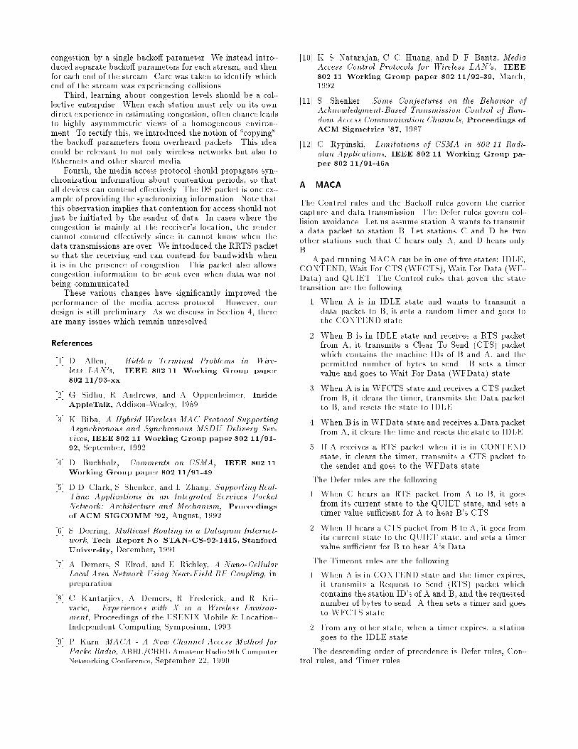
A MACA
The Control rules and the Backo rules govern the carriercapture and data transmission� The Defer rules govern col�lision avoidance� Let us assume station A wants to transmita data packet to station B� Let stations C and D be twoother stations such that C hears only A� and D hears onlyB�
A pad running MACA can be in one of �ve states� IDLE�CONTEND� Wait For CTS WFCTS�� Wait For Data WF�Data� and QUIET� The Control rules that goven the statetransition are the following�
�� When A is in IDLE state and wants to transmit adata packet to B� it sets a random timer and goes tothe CONTEND state�
�� When B is in IDLE state and receives a RTS packetfrom A� it transmits a Clear To Send CTS� packetwhich contains the machine IDs of B and A� and thepermitted number of bytes to send� B sets a timervalue and goes to Wait For Data WFData� state�
�� When A is in WFCTS state and receives a CTS packetfrom B� it clears the timer� transmits the Data packetto B� and resets the state to IDLE�
�� When B is in WFData state and receives a Data packetfrom A� it clears the time and resets the state to IDLE�
�� If A receives a RTS packet when it is in CONTENDstate� it clears the timer� transmits a CTS packet tothe sender and goes to the WFData state�
The Defer rules are the following�
�� When C hears an RTS packet from A to B� it goesfrom its current state to the QUIET state� and sets atimer value su�cient for A to hear B�s CTS�
�� When D hears a CTS packet from B to A� it goes fromits current state to the QUIET state� and sets a timervalue su�cient for B to hear A�s Data�
The Timeout rules are the following�
�� When A is in CONTEND state and the timer expires�it transmits a Request to Send RTS� packet whichcontains the station ID�s of A and B� and the requestednumber of bytes to send� A then sets a timer and goesto WFCTS state�
�� From any other state� when a timer expires� a stationgoes to the IDLE state�
The descending order of precedence is Defer rules� Con�trol rules� and Timer rules�
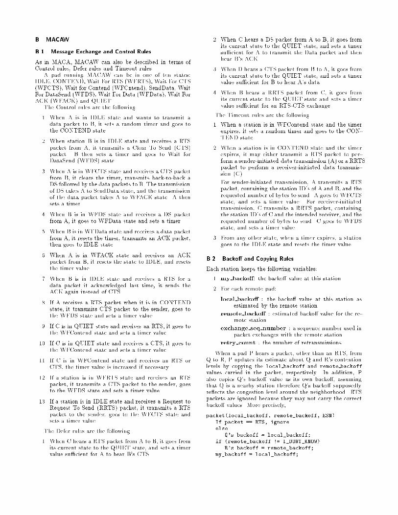
B MACAW
B�� Message Exchange and Control Rules
As in MACA� MACAW can also be described in terms ofControl rules� Defer rules and Timeout rules�
A pad running MACAW can be in one of ten states�IDLE� CONTEND� Wait For RTS WFRTS�� Wait For CTSWFCTS�� Wait for Contend WFCntend�� SendData� WaitFor DataSend WFDS�� Wait For Data WFData�� Wait ForACK WFACK� and QUIET�
The Control rules are the following�
�� When A is in IDLE state and wants to transmit adata packet to B� it sets a random timer and goes tothe CONTEND state�
�� When station B is in IDLE state and receives a RTSpacket from A� it transmits a Clear To Send CTS�packet� B then sets a timer and goes to Wait forDataSend WFDS� state�
�� When A is in WFCTS state and receives a CTS packetfrom B� it clears the timer� transmits back�to�back aDS followed by the data packets to B� The transmissionof DS takes A to SendData state� and the transmissionof the data packet takes A to WFACK state� A thensets a timer�
�� When B is in WFDS state and receives a DS packetfrom A� it goes to WFData state and sets a timer�
�� When B is in WFData state and receives a data packetfrom A� it resets the timer� transmits an ACK packet�then goes to IDLE state�
�� When A is in WFACK state and receives an ACKpacket from B� it resets the state to IDLE� and resetsthe timer value�
�� When B is in IDLE state and receives a RTS for adata packet it acknowledged last time� it sends theACK again instead of CTS�
�� If A receives a RTS packet when it is in CONTENDstate� it transmits CTS packet to the sender� goes tothe WFDS state and sets a timer value�
�� If C is in QUIET state and receives an RTS� it goes tothe WFContend state and sets a timer value�
��� If C is in QUIET state and receives a CTS� it goes tothe WFContend state and sets a timer value�
��� If C is in WFContend state and receives an RTS orCTS� the timer value is increased if necessary�
��� If a station is in WFRTS state and receives an RTSpacket� it transmits a CTS packet to the sender� goesto the WFDS state and sets a timer value�
��� If a station is in IDLE state and receives a Request toRequest To Send RRTS� packet� it transmits a RTSpacket to the sender� goes to the WFCTS state andsets a timer value�
The Defer rules are the following�
�� When C hears a RTS packet from A to B� it goes fromits current state to the QUIET state� and sets a timervalue su�cient for A to hear B�s CTS�
�� When C hears a DS packet from A to B� it goes fromits current state to the QUIET state� and sets a timersu�cient for A to transmit the Data packet and thenhear B�s ACK�
�� When D hears a CTS packet from B to A� it goes fromits current state to the QUIET state� and sets a timervalue su�cient for B to hear A�s data�
�� When B hears a RRTS packet from C� it goes fromits current state to the QUIET state and sets a timervalue su�cient for an RTS�CTS exchange�
The Timeout rules are the following�
�� When a station is in WFContend state and the timerexpires� it sets a random timer and goes to the CON�TEND state�
�� When a station is in CONTEND state and the timerexpires� it may either transmit a RTS packet to per�form a sender�initiated data transmission A� or a RRTSpacket to perform a receiver�initiated data transmis�sion C��
For sender�initiated transmission� A transmits a RTSpacket� containing the station ID�s of A and B� and therequested number of bytes to send� A goes to WFCTSstate� and sets a timer value� For receiver�initiatedtransmission� C transmits a RRTS packet� containingthe station ID�s of C and the intended receiver� and therequested number of bytes to send� C goes to WFDSstate� and sets a timer value�
�� From any other state� when a timer expires� a stationgoes to the IDLE state and resets the timer value�
B�� Backo� and Copying Rules
Each station keeps the following variables�
�� my backo�� the backo value at this station�
�� For each remote pad�
local backo� � the backo value at this station asestimated by the remote station�
remote backo� � estimated backo value for the re�mote station�
exchange seq number � a sequence number used inpacket exchanges with the remote station�
retry count � the number of retransmissions�
When a pad P hears a packet� other than an RTS� fromQ to R� P updates its estimate about Q and R�s contentionlevels by copying the local backoff and remote backoffvalues carried in the packet� respectively� In addition� Palso copies Q�s backo value as its own backo� assumingthat Q is a nearby station therefore Q�s backo supposedlyre�ects the congestion level around the neighborhood� RTSpackets are ignored because they may not carry the correctbacko values� More precisely�
packet�local�backoff� remote�backoff� ESN�If packet �� RTS� ignoreelse
Q�s backoff � local�backoff�if �remote�backoff �� I�DONT�KNOW�
R�s backoff � remote�backoff�my�backoff � local�backoff�

When a Pad P receives a packet from Pad Q to P� ifthe exchange seq number has increased� either the packetis initiating a new transmission or a successful handshakehas completed� In both cases� the backo values carriedin the packet should be the correct ones� Thus P updatesthe backo values of its own and that of Q�s� increases theESN and resets the retry count� Here P�s local backoff isa variable used temporarily when attempting an exchangewith Q its value is synchronized with P�s my backoff oncea successful handshake is done�
On the other hand� if the packet is a retransmission of anold packet� P assumes a collision occurred at Q�s end� andincreases the backo value for Q accordingly� Because thesum of the backo values of the two ends should be the sameindependently from at which end the collision has occurred�P upates its own backo value as the dierence between thesum and Q�s backo value as P estimated��
packet�local�backoff� remote�backoff� ESN�If �ESN � ESN for Q�
Q�s backoff � local�backoff�if �remote�backoff �� I�DONT�KNOW�
P�s local�backoff � remote�backoff�my�backoff � remote�backoff�
elseP�s local�backoff � my�backoff�
P�s ESN for Q � ESN �P�s retry�count with Q � �
else �� the packet is a retransmission ��Q�s backoff � local�backoff retry�count � ALPHA�if �remote�backoff �� I�DONT�KNOW�
P�s local�backoff � �local�backoff remote�backoff� Q�s backoff�else
P�s local�backoff � my�backoff�retry�count �
When pad P sends a packet to Q� it assigns the parametervalues in the packet� local backoff� remote backoff� andESN in the following way�
If �packet � RTS� ��or should it be at the beginning of a new packet��local�backoff �used in communicating with Q� � my�backoff�
remote�backoff � Q�s backoff �or I�DONT�KNOW��local�backoff � local�backoff used with Q�Send packet with local�backoff� Remote�backoff� ESN�
When a Pad P times out on a packet to Q�
Q�s backoff � retry�count � ALPHA�If reached max�retry�count�
P�s local�backoff used with Q � MAX�BACKOFF�Q�s backoff � I�DONT�KNOW�