Embed Size (px)
Citation preview
1
Mauna Kea Educational Academy
ROV name: Moby Team Name: Delta Sharks
Team members left to right: Jared Swanson, Clara Sheffield, Joshua Shigemitsu, Sam Watanabe – Team Captain, & Quintin Watanabe Mentors: Darryl Watanabe & Mark Sheffield
2
Table of Contents
Title: Page:
1. History of Submarine Rescue………………………..…....3-4
2. Abstract…..…………………………………………….…4-5
• ROV Frame………….………….……….…....6
• Features……………….………………..…..…7-9
• Electrical Schematic and spec sheets……...…10-12
• Bollard Testing…………………………….…13
3. Budget…………………..………………………….….…14
4. Reflections……………….………………………….…...15-17
5. Acknowledgements…………………………….…….….18
3
History of Submarine Rescue The use of submarines has had a major impact upon history. Submarines were primarily
reserved for war, dating as far back as 1775, when David Bushnell created the first sub designed
for combat. This hand-powered aquatic vessel, christened the Turtle, attempted to sink the
British warship HMS Eagle. This attempt ended in defeat, but it marked the first vehicle capable
of underwater submergence. Submarines would not play a major role in history until World War
I and II, when naval submarines were used for blockading incoming war and supply ships. The
effectiveness of the German U-boat is a testament of the uses of submarines in warfare. Karl
Doenitz, a distinguished U-boat commander, developed strategies and tactics that crippled WWII
allied countries by destroying over 3,000 ships, which included warships and much needed
supply ships. As the use of submarines was multiplying, both as weapons of war and as a means
of underwater research, the need for submarine rescue became prevalent.
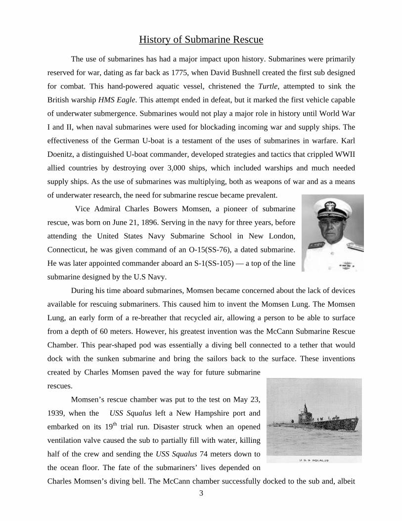
Vice Admiral Charles Bowers Momsen, a pioneer of submarine
rescue, was born on June 21, 1896. Serving in the navy for three years, before
attending the United States Navy Submarine School in New London,
Connecticut, he was given command of an O-15(SS-76), a dated submarine.
He was later appointed commander aboard an S-1(SS-105) — a top of the line
submarine designed by the U.S Navy.
During his time aboard submarines, Momsen became concerned about the lack of devices
available for rescuing submariners. This caused him to invent the Momsen Lung. The Momsen
Lung, an early form of a re-breather that recycled air, allowing a person to be able to surface
from a depth of 60 meters. However, his greatest invention was the McCann Submarine Rescue
Chamber. This pear-shaped pod was essentially a diving bell connected to a tether that would
dock with the sunken submarine and bring the sailors back to the surface. These inventions
created by Charles Momsen paved the way for future submarine
rescues.
Momsen’s rescue chamber was put to the test on May 23,
1939, when the USS Squalus left a New Hampshire port and
embarked on its 19th trial run. Disaster struck when an opened
ventilation valve caused the sub to partially fill with water, killing
half of the crew and sending the USS Squalus 74 meters down to
the ocean floor. The fate of the submariners’ lives depended on
Charles Momsen’s diving bell. The McCann chamber successfully docked to the sub and, albeit

4
some problems with the tether tangling, completed four trips and saved the 33 surviving crew
members aboard the submarine. This successful mission has been noted as the first and greatest
underwater rescue of all time.
Today, with the aid of modern advancements, countries have
begun to use remotely operated vehicles for submarine rescue. In
August 2005, the Scorpio 45, commissioned by the United Kingdom’s
Submarine Rescue Headquarters, untangled a Russian sub from fishing
nets, saving the lives of seven crew members. The Scorpio 45 is
equipped with 4 cameras, depth measuring systems, and sonar that can track transponders. These
were used to locate and analyze the condition of the downed sub. Upon locating the sub, the
ROV had a manipulator to bring life support equipment, and clear a docking port for the
emergency submersible to rescue the submariners. ROVs now play a critical role in submarine
rescues.
Abstract
Moby, our ROV, was built specifically to complete the required tasks for an underwater
rescue mission. Our goal in the design was not to overcomplicate the ROV. The steps involved
to complete this process of assembly included brainstorming, creating prototypes, building,
testing, and retesting.
The ROV frame consisted of PVC piping and aluminum bars to which we attached our tools.
PVC piping was used because it was not overly complicated to work with. The aluminum bars
were lightweight and had flat surfaces, which allowed for straightforward attachment of cameras
and other devices. Moby’s thrust was generated by means of a mixture containing 500 and 750
GPM bilge pumps.
5
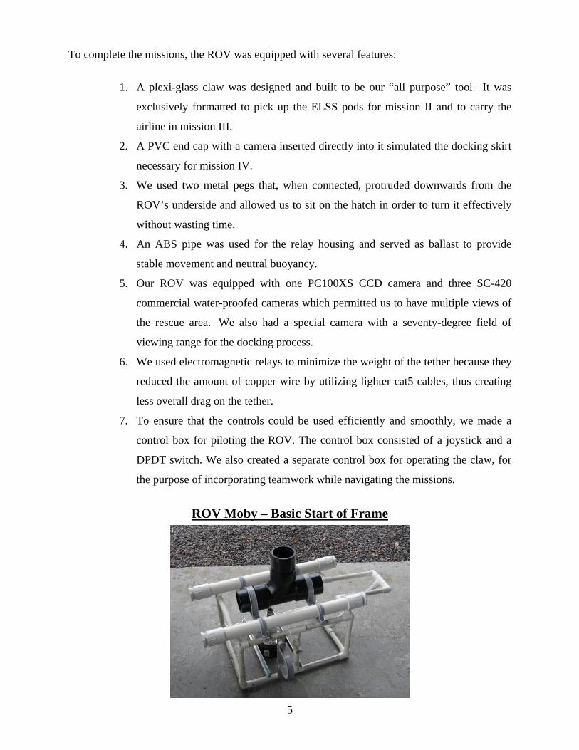
To complete the missions, the ROV was equipped with several features:
1. A plexi-glass claw was designed and built to be our “all purpose” tool. It was
exclusively formatted to pick up the ELSS pods for mission II and to carry the
airline in mission III.
2. A PVC end cap with a camera inserted directly into it simulated the docking skirt
necessary for mission IV.
3. We used two metal pegs that, when connected, protruded downwards from the
ROV’s underside and allowed us to sit on the hatch in order to turn it effectively
without wasting time.
4. An ABS pipe was used for the relay housing and served as ballast to provide
stable movement and neutral buoyancy.
5. Our ROV was equipped with one PC100XS CCD camera and three SC-420
commercial water-proofed cameras which permitted us to have multiple views of
the rescue area. We also had a special camera with a seventy-degree field of
viewing range for the docking process.
6. We used electromagnetic relays to minimize the weight of the tether because they
reduced the amount of copper wire by utilizing lighter cat5 cables, thus creating
less overall drag on the tether.
7. To ensure that the controls could be used efficiently and smoothly, we made a
control box for piloting the ROV. The control box consisted of a joystick and a
DPDT switch. We also created a separate control box for operating the claw, for
the purpose of incorporating teamwork while navigating the missions.
ROV Moby – Basic Start of Frame

6
The ROV’s frame consisted of PVC pipes and aluminum bars. As the backbone of the
ROV, the PVC pipes were used to provide a general shape that was undemanding and simple to
build. The aluminum bars were placed perpendicular to the frame on the lower and upper parts of
the ROV in order to further stabilize the craft and were used to attach the tools we needed for the
missions. Rebar was added to the frame to correct the balance of the ROV, which was offset by
the weight of the claw; we also used hose clamps for sheaths that protected the propellers from
damage.
When we first began brainstorming about the structure of the ROV, we decided a box would be
the most efficient shape to use – it provided an equal, stable, and centered frame that would excel
in all of the missions. We confirmed our choice of the box after discovering that this was the
shape of most professional ROVs. Although the format of our ROV was not as original as those
of others, we constructed the ROV with the mindset of performance rather than attractiveness.
The picture on the right is a
photograph of the finished frame. In the
end, the ballast pods were removed and
the design was kept simple; the frame
equally distributed the weight and kept
everything centered and protected; and
the claw was reinforced with an
aluminum bracket to ensure stability.
General specifications: Length: 45.7cm Width: 30.5cm Height: 20.3cm Weight: 89N (without tether) Weight: 111N (with tether)
7
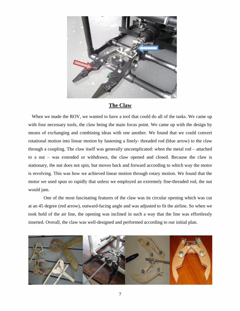
The Claw
When we made the ROV, we wanted to have a tool that could do all of the tasks. We came up
with four necessary tools, the claw being the main focus point. We came up with the design by
means of exchanging and combining ideas with one another. We found that we could convert
rotational motion into linear motion by fastening a finely- threaded rod (blue arrow) to the claw
through a coupling. The claw itself was generally uncomplicated: when the metal rod – attached
to a nut – was extended or withdrawn, the claw opened and closed. Because the claw is
stationary, the nut does not spin, but moves back and forward according to which way the motor
is revolving. This was how we achieved linear motion through rotary motion. We found that the
motor we used spun so rapidly that unless we employed an extremely fine-threaded rod, the nut
would jam.
One of the most fascinating features of the claw was its circular opening which was cut
at an 45 degree (red arrow), outward-facing angle and was adjusted to fit the airline. So when we
took hold of the air line, the opening was inclined in such a way that the line was effortlessly
inserted. Overall, the claw was well-designed and performed according to our initial plan.

8
The Pegs
When we were considering possibilities concerning the opening of the rescue sub’s hatch,
we established the idea to use steel pegs. The pegs were slightly bent on their ends to assist us in
affixing them to the docking skirt, where they could be inserted without difficulty to unlock the
hatch. For the peg housing, we cut a ½ inch PVC pipe into two pieces and glued the sections to
the mating skirt’s side. Because the pegs were made of steel and were therefore weighted, they
could be safely slid into the pipes and would not slip back out. Because one of our cameras was
placed within the skirt, we had a bird’s eye view of the hatch and were able to position the ROV
so the pegs went between the hatch’s cross supports. Our ROV used the pegs to rotate the hatch
by planting itself on the hatch door and turning itself clockwise, which then served to unbolt it.
The pegs were by far the simplest tool of the ROV, but without them the ROV would not
have been complete or proficient. They were yet another example of how simple things can
complete intricate tasks.
9
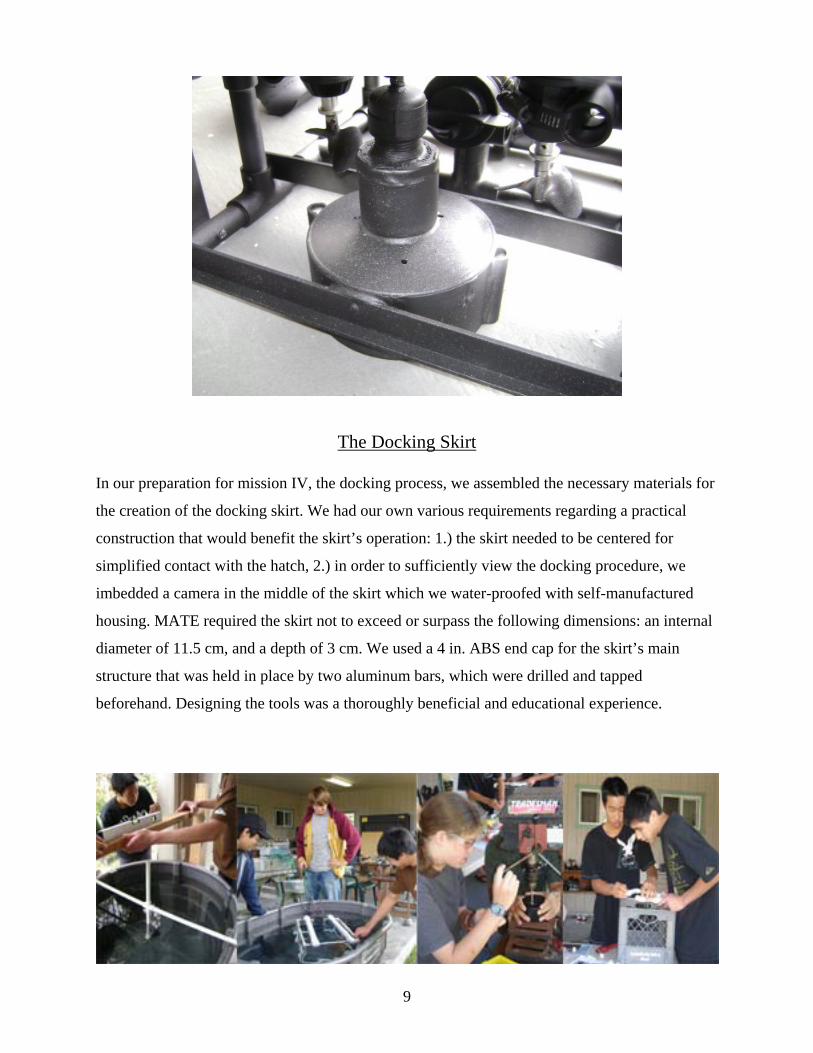
The Docking Skirt
In our preparation for mission IV, the docking process, we assembled the necessary materials for
the creation of the docking skirt. We had our own various requirements regarding a practical
construction that would benefit the skirt’s operation: 1.) the skirt needed to be centered for
simplified contact with the hatch, 2.) in order to sufficiently view the docking procedure, we
imbedded a camera in the middle of the skirt which we water-proofed with self-manufactured
housing. MATE required the skirt not to exceed or surpass the following dimensions: an internal
diameter of 11.5 cm, and a depth of 3 cm. We used a 4 in. ABS end cap for the skirt’s main
structure that was held in place by two aluminum bars, which were drilled and tapped
beforehand. Designing the tools was a thoroughly beneficial and educational experience.

10
Battery Fuse
MotorControl Box
Video Box CamerasMonitors
RelayBoard
Motors
Functional Block Diagram This diagram shows the electrical workings of our ROV. We used electromagnetic relays,
a joy stick with single pole-single throw switches, and two double pole-double throw switches. Last year we only hard-wired the motors to the switches and found that the tether significantly slowed down the ROV. Therefore, we decided that this year we needed to lighten the tether, and so we used electromagnetic relays that greatly cut down on the number of thick copper wires weighting down the tether. An electromagnetic relay is basically two single pole-single throw switches that are activated by an electromagnet. When we turned on the single pole-single throw switch at the surface, using, for example, the joystick, we completed the circuit which caused the current to run. Turning on the switch also activated the electromagnet, which in turn pulled the throws to make contact with the poles and completed the circuit, giving power to the load. We had two relays per direction that allowed us to switch the polarities, causing the motor to which the relays were connected to run backwards or forwards.
Electrical Schematic
11
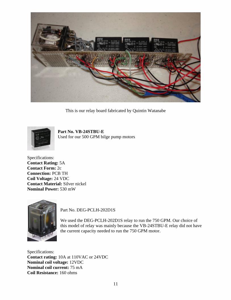
This is our relay board fabricated by Quintin Watanabe
Part No. VB-24STBU-E Used for our 500 GPM bilge pump motors
Specifications: Contact Rating: 5A Contact Form: 2c Connection: PCB TH Coil Voltage: 24 VDC Contact Material: Silver nickel Nominal Power: 530 mW
Part No. DEG-PCLH-202D1S We used the DEG-PCLH-202D1S relay to run the 750 GPM. Our choice of this model of relay was mainly because the VB-24STBU-E relay did not have the current capacity needed to run the 750 GPM motor.
Specifications: Contact rating: 10A at 110VAC or 24VDC Nominal coil voltage: 12VDC Nominal coil current: 75 mA Coil Resistance: 160 ohms

12
Cameras
Camera #1 This, our original camera, was a black and white PC100XS. It had a FOV (field of view) of 70
degrees with 410 lines of resolution, and it ran on 12 volts DC or 120 milliamps DC. Although
we made a water-proof housing for the camera, it experienced leaks. After some trouble
shooting, we found that our original epoxy seals were leaking, and so, to fix this problem, we
simply applied a stronger type of epoxy glue that took care of the seepage. This camera was
located in the docking skirt because it was necessary for us to have a large FOV. We were using
five PC100XS cameras but decided to replace all of them with the camera #2 type. We are
keeping the first cameras as a contingency plan in case the #2 cameras failed.
Camera #2 This camera was one of the three SC-420 commercial water-proofed cameras we used, which
ran on 12v DC or 120 milliamps DC. The FOV was 60 degrees and had 420 lines of resolution.
Despite the fact that these were commercially-made, submersible cameras, we still found a small
amount of water leakage – a dilemma solved by the application of Eco-bond epoxy.
Waterproof housing

13
Bollard Motor Testing
This simple “Bollard Test” enabled us to ascertain the amount of thrust each of our 500 and 750
GPM Mayfair bilge pumps contained. To perform this assessment we designed our own testing
device. The materials we used were: 1) One 500 and one 750 GPM bilge pump motor. 2) A
spring scale that showed the amount of thrust in pounds. 3) A large trough filled with water. 4) A
wooden 2x4 on which to fasten the spring scale. 5) A self-constructed cross that held a motor and
was attached to the spring scale.
The outcome of the test was:
500 GPM Mayfair bilge pump motor – 60mm two-bladed propeller thrust
Forward – 1.1 lb or 4.89 N
Backward – 0.8 lb or 3.56 N
750 GPM Mayfair bilge pump motor – 60mm two-bladed propeller thrust
Forward 1.9 lb or 8.5 N
Reverse 1.5 lb or 6.7 N
After testing all of our Mayfair bilge pumps we decided to test the outcome of joining
two double-bladed 60 mm. propellers. The picture above shows our experiment and how it was
fastened to the bilge pump. We found that this did not work and had actually reduced the amount
of Newtons of force our 500 and 750 GPM bilge pumps could produce.
Mayfair Bilge pump w/ two 60 mm props joined together Performing a Bollard test

14
2009 ROV Expenditures
Items Quantity Cost Use Vendor ROV Frame: Bilge Pump Motors 5 $113.54 Propulsion One Source Boating Supply PVC Fittings $ 45.06 Frame Ace, Home Depot, HPM PVC Glue 1 $ 7.62 Frame Home Depot 5 Minute Epoxy 1 $ 12.00 Frame Ace Screws $ 12.56 Frame, Claw Design Ace, Home Depot Thread Lock 1 $ 4.49 Claw Design Ace Hose Clamps 4 $ 2.80 Propeller shield Home Depot Teflon Tape 1 $ 1.30 Water tight Seal Home Depot ABS Fittings 2 $ 3.77 Relay House Home Depot PVC Fittings 2 $ 56.80 Relay House Central Supply Brass Swivel Snap 1 $ 2.40 Tether Home Depot Cat 5 Cables 100 ft. $ 30.00 Tether IC Supply Cable Ties 1 case $ 8.00 Tether, Frame Home Depot Control Box: Rocker switch 1 $ 10.00 Control switch IC Supply Plastic Box 1 $ 4.93 Claw control box Radio Shack 2A Relays $ 56.70 Control Systems All Electronics 5 Amp Relays $ 40.00 Control Systems Radio Shack Terminal Connectors $ 7.47 Electronic Home Depot Connections Cameras: Video Switch 1 $ 23.00 Camera Switching Wal-Mart Cameras $ 53.52 Underwater Sight All Electronics Budget $700.00 Actual Cost: $495.42 Projected per student hours: 100 Combined student hours: 500 Projected counselor hours: 80
15
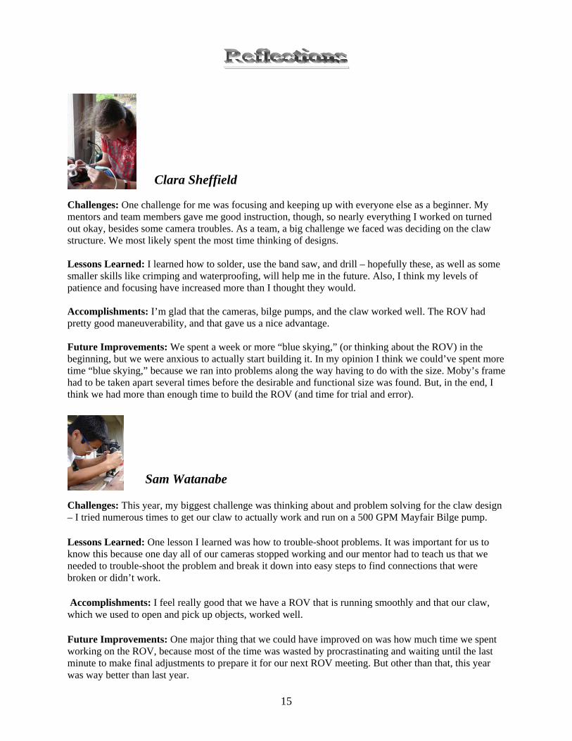
Clara Sheffield
Challenges: One challenge for me was focusing and keeping up with everyone else as a beginner. My mentors and team members gave me good instruction, though, so nearly everything I worked on turned out okay, besides some camera troubles. As a team, a big challenge we faced was deciding on the claw structure. We most likely spent the most time thinking of designs. Lessons Learned: I learned how to solder, use the band saw, and drill – hopefully these, as well as some smaller skills like crimping and waterproofing, will help me in the future. Also, I think my levels of patience and focusing have increased more than I thought they would. Accomplishments: I’m glad that the cameras, bilge pumps, and the claw worked well. The ROV had pretty good maneuverability, and that gave us a nice advantage. Future Improvements: We spent a week or more “blue skying,” (or thinking about the ROV) in the beginning, but we were anxious to actually start building it. In my opinion I think we could’ve spent more time “blue skying,” because we ran into problems along the way having to do with the size. Moby’s frame had to be taken apart several times before the desirable and functional size was found. But, in the end, I think we had more than enough time to build the ROV (and time for trial and error). Sam Watanabe
Challenges: This year, my biggest challenge was thinking about and problem solving for the claw design – I tried numerous times to get our claw to actually work and run on a 500 GPM Mayfair Bilge pump.
Lessons Learned: One lesson I learned was how to trouble-shoot problems. It was important for us to know this because one day all of our cameras stopped working and our mentor had to teach us that we needed to trouble-shoot the problem and break it down into easy steps to find connections that were broken or didn’t work.
Accomplishments: I feel really good that we have a ROV that is running smoothly and that our claw, which we used to open and pick up objects, worked well.
Future Improvements: One major thing that we could have improved on was how much time we spent working on the ROV, because most of the time was wasted by procrastinating and waiting until the last minute to make final adjustments to prepare it for our next ROV meeting. But other than that, this year was way better than last year.
16
Joshua Shigemitsu Challenges: One of the most challenging tasks was opening the hatch for the ELSS pods. The process of turning the hatch required many hours of brainstorming. The first design we came up with was the placement of two prongs underneath our ROV so that, when we rotated the ROV, the prongs would open the hatch. This design, however, could have hindered our chances at completing the docking tasks, so we were initially concerned about using it. The ballast and center of balance were also very challenging to correct. Trouble Shooting: Many problems were not as difficult as they seemed. On many of our first dives we found that our motors and cameras malfunctioned, but when we checked our connections, everything was working accordingly. Of course, we were very perplexed until we checked our battery – the old battery was not able to give us the required voltage. With the replacement of the battery, everything worked fine. Lessons Learned: I think I have learned, and now understand, how vital working as a team can be. By working together and using each person’s abilities to their fullest potential, we operated at maximum efficiency. Another thing I learned was the steps needed to design a tool. I designed our claw and learned that, by creating models, I was able to better understand its mechanics. I created three models before we found the design we wanted. Future Improvements: Looking back, I would take the extra measures of finding the buoyancy and center of balance. I didn’t realize how crucial these were for landing on the hatch and the docking port until we sent the ROV underwater. Jared Swanson Challenges: I joined the ROV team because I wanted to have an outlet for my creative side. I enjoy building things and taking things apart because running into problems and fixing them is fun to me, and I felt like I could do a lot if I joined the ROV team. The biggest challenge for me was the slow pace. I like doing things – I don’t like sitting around talking about doing things. I like jumping in, getting it done, and doing all the different tasks. I love power tools; they make a job go fast. Troubleshooting: The troubleshooting part was also fun even though I got stressed if I couldn’t get something to work. When we found the answer, it made all the stressing worth it. I am very good at visualizing what needs to happen. I like taking things apart to see how they work, although I admit that sometimes I can’t put them back together. Lessons Learned: One of the many lessons I learned was how to drill and tap a hole. It was a very fun process and it opened a whole new dimension of mechanics. I also learned how important safety is: I was cutting a wire with wire cutters, and when I snipped through the wire, it was like the wire was spring-loaded – it flew right at my eye. Luckily I had safety glasses; otherwise I might have had one less eye to see with.
17
Quintin Watanabe
Challenges and Lessons Learned: There were a couple of challenges that I struggled with while building the ROV. The first would have been the electrical workings of our complex machine. Looking at and understanding the bewildering complexity of the electromagnetic relays was one of the things that I struggled with. The second would be soldering for the first time on a circuit board: it was very time-consuming and difficult to solder such small connections. However, I learned a great deal about the flow of electricity and how it affects the load depending upon how the polarities line up. Teamwork Issues, Strategies, and Lessons Learned: This year’s team worked together extremely well. We had two team members back from last year (three including me), so we knew what we were doing and we could instruct the new teammates. We also had people who liked to work with mechanics, and others who liked to work with electronics. This was beneficial because the tasks could be spread evenly amongst the teammates. Accomplishments: This year I did a lot more with electronics, and our control system was much more complicated than it was last year. I think one reason that I accomplished more this year was because I knew how to do more than I did last year. For example, I have become more proficient at soldering than I previously was, and I was able to fabricate and produce most of the control system. In a sense this was my personal and professional accomplishment, because I can use what I have learned from this and apply it to a future occupation. Future Improvements: What we need to improve on next year is team leadership. Understandably if someone doesn’t know what he is doing, then it is hard to take action. However, if the person does know what to do, and what is expected of him, then the road is already paved and all he has to do is walk it. Because I did this last year, I should have taken more leadership and helped others understand what needs to be done and how to do it. Time management was also another big issue, as was waiting until the last minute to do things. We could change this by planning out our work and actually sticking to the plan.

18
Acknowledgments
Newton’s first law of motion states, “An object at rest will remain at rest: and an object in motion will remain in motion until an external force is applied.” We would like to recognize and thank all the following people for getting us into motion and keeping us moving toward our goals. Whether it was by offering redirection or motivational advice to encourage us, all their hard work and efforts are greatly appreciated.
• Darryl Watanabe – Head Advisor: For his driving spirit to keep us focused and for giving us confidence not to give up when times became complicated or difficult.
• Mark Sheffield – Mentor: For uniting us to strategize, for training us in mental
discipline, and for urging us to think things out so that we would have as minimal an amount of errors as possible.
• Cindy Fong – Hilo High School Advisor: For her support and willingness to facilitate
other teams and to give them an abundance of opportunities in learning and gaining valuable knowledge.
• Cindy Watanabe – Cook: For her appetizing meals that fed us while we worked through
extensive evenings. • Parents – Drivers: For driving the team to and from meetings and for making all the
gatherings possible. • Marleena Sheffield – We would also like to recognize one of our spectacular editors
who helped us edit this technical document in so many ways. • Hilo High Pool – Practice: For allowing all the teams to do practice rounds and offering
them a chance to practice with their ROV if they had not previously had a place to do so. • Kawamoto Pool – Place of the competition: For letting all the teams use the pool for the
day. Sources Cited National Geographic. “Major Submarine Disasters” accessed May 21, 2009 http://www.nationalgeographic.com/k19/disasters_detail3.html
Naval Technology.com “LR5 Submersible Submarine Rescue Vessel, United Kingdom” accessed May 21, 2009 http://www.naval-technology.com/projects/lr5/
World War 2 Submarines “Submarine Warfare in World War 2” accessed May 21, 2009 http://www.2worldwar2.com/submarines.htm
FleetSubmarine.com “Vice Admiral Charles B. Momsen” posted 2002, accessed May 21, 2009 http://www.fleetsubmarine.com/momsen.html