Embed Size (px)
Citation preview

MATTHEWSDANIEL SURVEY & ENGINEERING GUIDELINES SECTION III – DRY TRANSPORTATION
MatthewsDaniel
Survey & Engineering Guidelines, Section III - Dry Transportation MD Form 9103 A4, Issue 03, 08/2007
MATTHEWSDANIEL
SURVEY & ENGINEERING GUIDELINES
SECTION III
GUIDELINES FOR
DRY TRANSPORTATION
FEBRUARY 2005


MATTHEWSDANIEL SURVEY & ENGINEERING GUIDELINES SECTION III – DRY TRANSPORTATION TABLE OF CONTENTS
MatthewsDaniel
Survey & Engineering Guidelines, Section III - Dry Transportation MD Form 9103 A4, Issue 03, 08/2007
TABLE OF CONTENTS
1. INTRODUCTION......................................................................................................... 1
1.1 Purpose of Document ................................................................................... 1
1.2 Principles for Approvability.......................................................................... 2
1.3 Specific Information Needed To Carry Out Approval ................................ 3
1.4 Certificates of Approval ................................................................................ 4
1.5 Procedures and Contingency Plans ............................................................ 4
1.6 Reference Documents................................................................................... 4
2. PLANNING OF MARINE OPERATIONS.................................................................... 5
2.1 General ........................................................................................................... 5
2.2 Transportation Manual.................................................................................. 5
2.3 Considerations During The Preparation Process ...................................... 6
3. ENVIRONMENTAL CRITERIA FOR TOWING AND DEPARTURE........................... 8
3.1 Environmental Return Period....................................................................... 8
3.2 Wind................................................................................................................ 9
3.3 Waves ............................................................................................................. 9
3.4 Other Metocean Conditions........................................................................ 10
3.5 Departure Criteria and Weather Forecasting ............................................ 10
4. DETERMINATION OF MOTIONS AND STABILITY ................................................ 12
4.1 General ......................................................................................................... 12
4.2 Motion Response......................................................................................... 12
4.3 Standard Criteria ......................................................................................... 13
4.4 IMO Criteria .................................................................................................. 14
4.5 Recommendation ........................................................................................ 17
4.6 Intact Stability.............................................................................................. 17
4.7 Dynamic Stability......................................................................................... 18
4.8 Damaged Stability ....................................................................................... 18
5. GRILLAGE/CRIBBING, SEAFASTENINGS AND CARGO LOADS........................ 20
5.1 General ......................................................................................................... 20
5.2 Loads During Transportation..................................................................... 20
5.3 Grillage and Seafastening Strength........................................................... 21
5.4 Transport Vessel and Cargo Strength....................................................... 24
5.5 Internal Seafastenings ................................................................................ 24

MATTHEWSDANIEL SURVEY & ENGINEERING GUIDELINES SECTION III – DRY TRANSPORTATION TABLE OF CONTENTS
MatthewsDaniel
Survey & Engineering Guidelines, Section III - Dry Transportation MD Form 9103 A4, Issue 03, 08/2007
5.6 Cribbing........................................................................................................ 24
5.7 Cargo Protection ......................................................................................... 25
6. OPERATIONAL ASPECTS ...................................................................................... 26
6.1 Pre-Sailaway Checks................................................................................... 26
6.2 Transport Vessel Routes ............................................................................ 26
6.3 Communication and Reporting.................................................................. 27
7. REQUIREMENTS FOR TRANSPORT VESSELS.................................................... 28
7.1 General ......................................................................................................... 28
7.2 Documentation ............................................................................................ 28
7.3 Technical Information ................................................................................. 29
7.4 Ballast and Pumping Systems ................................................................... 29
7.5 Regulatory Matters ...................................................................................... 29
7.6 Manning........................................................................................................ 30
MATTHEWSDANIEL SURVEY & ENGINEERING GUIDELINES SECTION III – DRY TRANSPORTATION PAGE 1 1. INTRODUCTION
MatthewsDaniel
Survey & Engineering Guidelines, Section III - Dry Transportation MD Form 9103 A4, Issue 03, 08/2007
1. INTRODUCTION
1.1 Purpose of Document
This document is intended for MatthewsDaniel use only and has been prepared by MatthewsDaniel (MD) for use when MD acts as Marine Warranty Surveyor. It addresses likely main concerns based on experience. This document does not deal comprehensively with all concerns which will need to be addressed or even, where a particular matter is addressed, does this document attempt to set out the definitive view of MD for all situations. This document gives guidelines which should be reviewed in each particular case by the owner and MD engineer/surveyor to ensure that the particular circumstances of the transport are addressed in a way which is considered to mitigate identified hazards.
These guidelines cover the marine aspects of drilling rigs, MODUs, TLPs, Spars, general project cargo, and other floating and non-floating heavy cargoes, tie-down, seafastening, and transport onboard dry transport and general cargo vessels.
Marine surveying is an activity involving experienced personnel identifying possible risks to a transportation and consulting on mitigating the risks to a level which is as low as reasonably practical (for which MD shall be deemed the approving authority) to approve the venture to proceed, on behalf of underwriters.
The term "Marine Surveying" as used herein is an activity, which covers:
• Review of plans, drawings, documents and procedures to verify compliance with final MD acceptance criteria
• Survey of vessels, structures and equipment as deemed appropriate
• Confirmation of approval of the activity or venture by issue of a MD Certificate of Approval
All the above activities will be based on an acceptance criteria for which MD shall be deemed the approving authority.
All reports and certificates are issued solely for the use of MD, its clients and other authorized entities agreed by MD and the client.
The review and approval by MD is not meant as a substitute for the independent judgment of professional designers, naval architects, marine engineers, owners, operators, masters and crew, nor as a substitute for the quality control procedures of fabricators, builders, suppliers, materials, machinery or equipment. MD acts through its engineers and marine surveyors or others who are believed by MD to be skilled and competent.

MATTHEWSDANIEL SURVEY & ENGINEERING GUIDELINES SECTION III – DRY TRANSPORTATION PAGE 2 1. INTRODUCTION
MatthewsDaniel
Survey & Engineering Guidelines, Section III - Dry Transportation MD Form 9103 A4, Issue 03, 08/2007
The user of MD services is responsible for ensuring compliance with all applicable laws, regulations and other government directives and orders related to a unit, its machinery and equipment, or their operation. Nothing contained in any guideline or approval certificate issued by the MD shall be deemed to relieve any other entity of its duty or responsibility to comply with all applicable laws, including those related to the environment.
MD approval represents that a transportation adheres to a minimal standard satisfactory to MD for purposes of fulfilling the marine warranty survey role. The validity, applicability and interpretation of any approval to meet a minimal standard remains in the sole judgment of MD. MD is not responsible for the consequences arising from the use by other parties.
MD will conduct both an engineering and operational review on the proposed seafastening, on the transport, which will include, but not be limited to, the vessel and seafastening acceptance.
Timely completion of engineering and operational review is dependent on quality and completeness of information supplied. Normal practice is for the time period to be not less than a 2-4 week turnaround prior to loading. Early submission is a prudent practice in order to avoid delay.
1.2 Principles for Approvability
The purpose of this Section is to provide general guidance on the principles of approvability. Generally, MD looks for the following characteristics in developing acceptance criteria for a particular transportation:
• The equipment and vessels are suitable for their intended use;
• There is redundancy in the equipment provided, to cover likely contingencies;
• The operation is designed taking into account the statistical weather extremes for the area and season, or the operating weather conditions, chosen at values smaller than the specified design criteria, and the weather is forecast for a period long enough to complete the operation;
• The operations are planned, in nature and duration, such that accidental situations, breakdowns or delays have a very low probability of occurrence and are all covered by contingency actions;
• Adequate plans have been developed for a safe step-by-step execution of the operation, with clear indications of the chain of command;
• Suitably experienced and qualified personnel conduct the operations.

MATTHEWSDANIEL SURVEY & ENGINEERING GUIDELINES SECTION III – DRY TRANSPORTATION PAGE 3 1. INTRODUCTION
MatthewsDaniel
Survey & Engineering Guidelines, Section III - Dry Transportation MD Form 9103 A4, Issue 03, 08/2007
1.3 Specific Information Needed To Carry Out Approval
Specifically, in order for MD to issue a Certificate of Approval, MD will typically review the following, including, but not limited to:
• The capability of the selected vessel to carry the cargo, including overhang, without damage;
• The proposed voyage route, season, and design environmental conditions;
• The vessel design motions leading to cargo and seafastening loads and stresses;
• The strength of the cribbing to withstand static and wind and motion induced dynamic transportation loads;
• The strength of the cargo to withstand static and wind and motion induced dynamic transportation loads;
• The weather protection of the cargo;
• The seafastening of items and substructures within the cargo;
• The weather conditions and ability to forecast along the proposed route;
• Ports of refuge along the proposed route.
Fatigue damage is not included in consideration of the transported cargo unless specifically required by the client.
In order of MD to issue a Certificate of Approval for loading and offloading MD will typically conduct an engineering review of the following, including, but not limited to:
• The location details, water depth, tidal conditions, and meteorological exposure;
• The vessel moorings and cargo moorings during the loading operation;
• Stability and ballasting conditions during the loadout and discharging operation and the critical parts of deballasting/ballasting operation;
• Cribbing position and securing during submergence;
• Transportation and handling arrangements for the cargo;
• Design of rigging arrangement and connection points;
• Capacity and certification of lifting equipment;
• Cargo positioning arrangements, including guideposts, guides, and bumpers;
• Reactions between vessel and cargo;
• Limiting weather conditions for the operations;
• Vessel design motion response for vessel as loaded with MODU;
• Leg bending moment calculations for MODU based on vessel design motion response;

MATTHEWSDANIEL SURVEY & ENGINEERING GUIDELINES SECTION III – DRY TRANSPORTATION PAGE 4 1. INTRODUCTION
MatthewsDaniel
Survey & Engineering Guidelines, Section III - Dry Transportation MD Form 9103 A4, Issue 03, 08/2007
1.4 Certificates of Approval
MD will conduct an engineering review on all items issued above and based on this review resulting in compliance with MD standards, MD will issue a ledger to the assured indicating MD's principle approval to the transport of the MODU onboard the heavy-lift vessel on the intended voyage.
A Certificate of Approval will be issued on site, immediately prior to the loading and/or transportation departure, by the MD Surveyor in attendance when he is satisfied that the preparations for loading and/or transportation are complete, that the operation scheduled is approved in the opinion of MD acting through its surveyor, and that the weather forecast is satisfactory for the purposes for which the Approval is intended.
1.5 Procedures and Contingency Plans
Procedures shall be developed and included in the seafastening and transportation manual. This manual shall also address any possible need to deviate from the established procedures and shall describe appropriate contingency plans.
1.6 Reference Documents
1. ISO 13819 "Offshore structures for petroleum and natural gas industries" Marine Operations (in preparation);
2. CSA Standard S475, Sea Operations, 1992;
3. Devoy, S.D. & van Hoorn, F. "The Dry Transport of the Green Canyon "Tension Leg Wellhead Platform" by a Semi-Submersible Heavylift Ship," OTC Paper No. 6471, 1990;.
4. Code of Safe Practice for Cargo Stowage and Securing, 2003 Edition, IMO IA292E, London.
MATTHEWSDANIEL SURVEY & ENGINEERING GUIDELINES SECTION III – DRY TRANSPORTATION Page 5 2. PLANNING OF MARINE OPERATIONS
MatthewsDaniel
Survey & Engineering Guidelines, Section III - Dry Transportation MD Form 9103 A4, Issue 03, 08/2007
2. PLANNING OF MARINE OPERATIONS
2.1 General
Marine operations shall be planned so as to develop procedures, which are both conservative and practical. The planning shall be based on the use of well-proven principles, techniques, systems and equipment to ensure against major economic losses. The possible impact of the transport on the environment shall also be considered. For projects in which new techniques are applied or existing technology is extended, the documentation shall justify the prudence of the operation. The feasibility of extending existing technology and applying new techniques shall be documented.
All planning shall be based where possible on the assumption that it may be necessary to interrupt or reverse the operation.
Ports, which may be used as ports of refuge during the transport, shall be identified and surveyed for suitability prior to the operation, if possible.
Planning should be based on reasonable timing. A delay in timing of a severe part of the route can change the risk equation significantly.
2.2 Transportation Manual
A Transportation Manual covering all normal, contingency and emergency aspects of the operation shall be prepared for review and approval by MD. This may include loadout information which would be subject to the MatthewsDaniel Guideline for Marine Loadouts.
The manual shall include details of the following:
• Description of planned operation.
• Organization and communication.
• Site information for loading and unloading, and port of departure and arrival location.
• Description and drawings of the structure(s) to be transported.
• Environmental criteria for transport from appropriate sources.
• Grillage and seafastenings – review results of structural analysis.
• Vessel strength analysis, global and local.
• Temporary mooring arrangement.
• Transport vessel(s) information and transport suitability survey.
• Detailed stowage arrangement(s), including minimum clearances, if critical.
MATTHEWSDANIEL SURVEY & ENGINEERING GUIDELINES SECTION III – DRY TRANSPORTATION Page 6 2. PLANNING OF MARINE OPERATIONS
MatthewsDaniel
Survey & Engineering Guidelines, Section III - Dry Transportation MD Form 9103 A4, Issue 03, 08/2007
• Ballast plan, intact, and damaged stability calculations.
• Ballast water exchange procedures, if applicable.
• Summary of the loading condition and motion analysis.
• Transportation route and possible ports of refuge.
• Transport procedure.
• Weather forecast or weather routing services and schedule.
• Recording and reporting procedures.
• Contingency and emergency action plans including contact numbers.
The MD Warranty Surveyor will conduct a full survey of the transport vessel with all equipment to ensure all is in satisfactory condition and where applicable in MD Surveyor's opinion, associated certificates are valid.
Documentation to confirm that visual examination and/or non-destructive examination (NDE) of the welds on the grillage and seafastenings has been satisfactorily carried out shall be prepared. A competent person shall carry out these tests and the necessary records shall be made available for review.
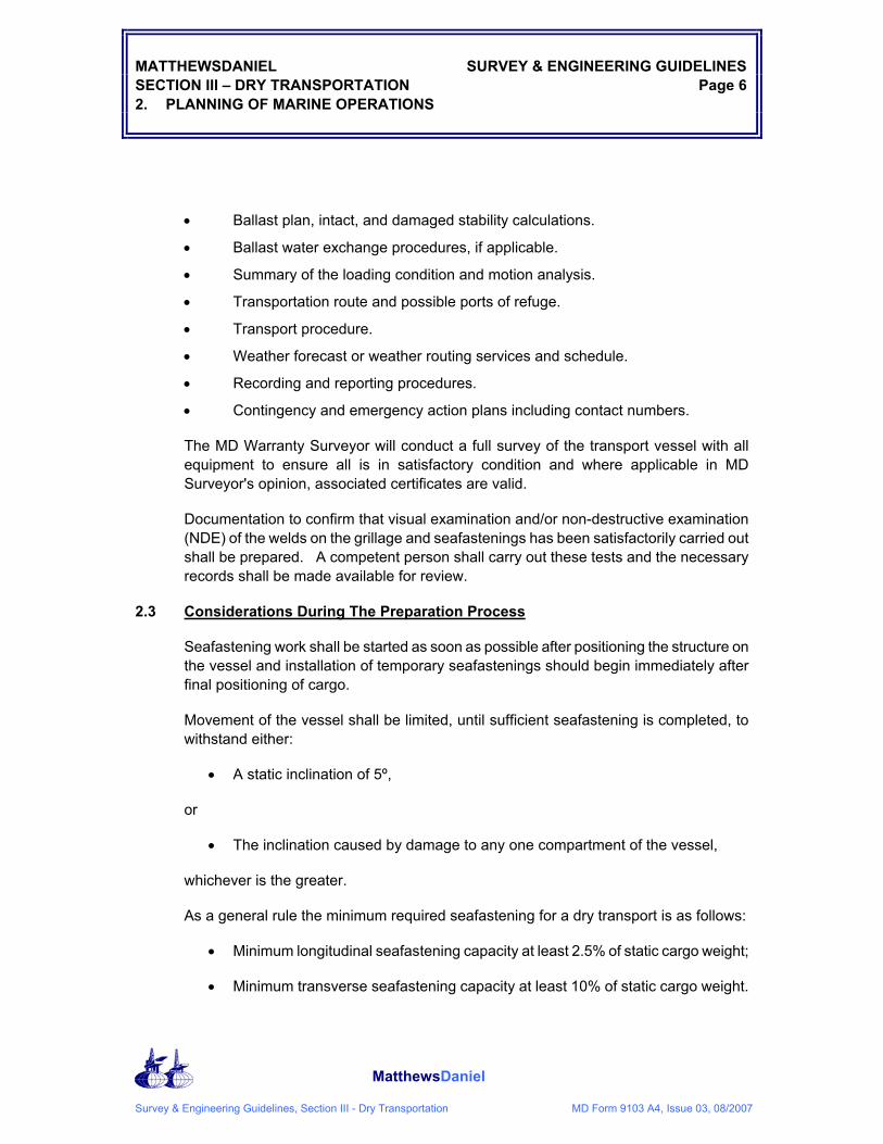
2.3 Considerations During The Preparation Process
Seafastening work shall be started as soon as possible after positioning the structure on the vessel and installation of temporary seafastenings should begin immediately after final positioning of cargo.
Movement of the vessel shall be limited, until sufficient seafastening is completed, to withstand either:
• A static inclination of 5º,
or
• The inclination caused by damage to any one compartment of the vessel,
whichever is the greater.
As a general rule the minimum required seafastening for a dry transport is as follows:
• Minimum longitudinal seafastening capacity at least 2.5% of static cargo weight;
• Minimum transverse seafastening capacity at least 10% of static cargo weight.

MATTHEWSDANIEL SURVEY & ENGINEERING GUIDELINES SECTION III – DRY TRANSPORTATION Page 7 2. PLANNING OF MARINE OPERATIONS
MatthewsDaniel
Survey & Engineering Guidelines, Section III - Dry Transportation MD Form 9103 A4, Issue 03, 08/2007
Final seafastening connections should be made with the vessel in ballast condition as close as practical to the transport condition.
If manhole covers have been removed, all manhole covers shall be replaced as soon as practical after loadout.
Any holes cut for ballasting purposes shall be closed as soon as practical and the barge certification reinstated before sailaway.

MATTHEWSDANIEL SURVEY & ENGINEERING GUIDELINES SECTION III – DRY TRANSPORTATION Page 8 3. ENVIRONMENTAL CRITERIA FOR TOWING AND DEPARTURE
MatthewsDaniel
Survey & Engineering Guidelines, Section III - Dry Transportation MD Form 9103 A4, Issue 03, 08/2007
3. ENVIRONMENTAL CRITERIA FOR TOWING AND DEPARTURE
3.1 Environmental Return Period
A set of limiting metocean criteria should be established dependent on the duration of the transport. The design storm environment is not used for calculating bollard pull requirements, which are covered in Section 9.3.
Where design environmental criteria are selected on a seasonal basis, due consideration should be given to the possibility of acceleration or slippage to the project schedule, and the consequence of a worse weather condition for limiting the selected environmental criteria.
For all operations taking longer than forecastable conditions, extreme data analysis should be used for appropriate return periods or acceptable probability of exceedance, to set design criteria. Such operations are termed "unrestricted" operations.
When operations are within forecastable periods, specific limiting operational criteria should be determined with the operation duration dictated by the weather forecastable window. An iteration process is normally needed at the design stage to arrive at an acceptance criteria for the whole operation. Early participation with the MD Marine Surveyor is helpful to this process.
All dry transports shall be designed to withstand the seasonal 10-year return period extreme environmental conditions or appropriate probability of exceedance standard, for the most exposed part of the route. It is recommended that the seasonal analysis of extreme conditions take into account tropical revolving storm characteristics. For example, Northern hemisphere operations can be divided into 4 three month periods coinciding with the four seasons for summer, fall, winter, and spring operations. Southern Hemisphere and Tropical operations should take due account of the possibility of periods of extreme weather and monsoon conditions respectively.
For long duration transports passing through areas having different characteristic sea states, the worst sea state for the route shall be identified and used in the design of the cargo, cribbing or grillage, and seafastenings.
For limited distance transporting operations with a short planned duration, reduced environmental criteria may be proposed for approval by MD.
Environmental data shall be referred to by the following nomenclature:
• V1MIN maximum 1-minute mean wind speed at 10 m above sea level.
• HS Significant wave height (average of the highest one-third).
• HMAX Maximum wave height.
• TZ Zero crossing wave period.

MATTHEWSDANIEL SURVEY & ENGINEERING GUIDELINES SECTION III – DRY TRANSPORTATION Page 9 3. ENVIRONMENTAL CRITERIA FOR TOWING AND DEPARTURE
MatthewsDaniel
Survey & Engineering Guidelines, Section III - Dry Transportation MD Form 9103 A4, Issue 03, 08/2007
• Tm Mean wave period (Tm = 1.087 * Tz).
• TP Wave period of peak spectral density (Tp = 1.41 * Tz).
3.2 Wind
The design wind speed shall be based on the 1 minute sustained wind speed at a height of 10 meters above still water level.
The seasonal variation of wind speeds can be taken into account in determining extreme values.
3.3 Waves
The design wave height shall be based on the significant height (HS) associated with wind speeds referred to in Section 3.1. A range of wave periods should be investigated for any sensitivity in the operation based on TP listed below.
It is recommended that motions shall be investigated for a range of values of peak period (TP), particularly if resonant conditions are possible. The range of values, defined in terms of significant wave height, as recommended by ISSC (International Ships Structures Congress), is as follows:
√ (13 HS) < TP < √ (30 HS)
where TP = peak period
In the maximum sea state under consideration, the natural period of motion of the unit may be below the above range. In this case, motions shall also be determined in the highest sea state, which may, according to the formula above, have a peak period which is equal to the unit's natural period of motion.
For units that have a natural period of motion greater than √ (30 HS) and which may pass through areas prone to long period swells, then motions due to swell shall also be determined and considered.
In open waters, waves will usually be considered as being long crested. However, in some areas it may be demonstrated that it is appropriate to consider the waves to be short crested and to apply a spreading factor to the wave energy. This is particularly appropriate for fatigue sensitive transports.
If a detailed analysis of the joint probability distribution of significant wave height versus peak wave period is carried out, the following criteria may be applied:

MATTHEWSDANIEL SURVEY & ENGINEERING GUIDELINES SECTION III – DRY TRANSPORTATION Page 10 3. ENVIRONMENTAL CRITERIA FOR TOWING AND DEPARTURE
MatthewsDaniel
Survey & Engineering Guidelines, Section III - Dry Transportation MD Form 9103 A4, Issue 03, 08/2007
a) Analyze the transport for the design storm wave height for the most probable value of peak period:
(Tp) +/- 1 sec and
b) Analyze the transport for combinations of significant wave height and peak period having the same joint probability of occurrence as the design storm wave height and the most probable peak period. The effect of swell shall be considered in the above criteria.
3.4 Other Metocean Conditions
Other factors and combinations may be critical and these may include:
• Combinations of wind, wave, current,
• Bad visibility;
• Sea icing, icing on superstructure, exceptional low temperature;
• Water density and salinity;
• Tidal currents.
Where the presence of ice may affect the operation, ice movement records, forecasts and monitoring shall be used to assist planning of the operation.
3.5 Departure Criteria and Weather Forecasting
The departure of a transport will only be approved after receipt of a favorable 72-hour weather forecast covering the intended initial route.
During the transport, a weather forecast shall be obtained from a recognized meteorological agency which has detailed knowledge of the area covered by the forecast and which customarily provides services for offshore transportation or weather routing. Weather forecasts shall be provided at 12-hour intervals, and shall contain forecasts for the next 24, 48 and 72 hours, with the weather outlook for the coming 3 to 5 days period. The vessel's Captain should receive weather forecasts and weather maps, in written form, which is generally done by having an onboard weather facsimile machine or continuous email capability.
The forecast should be in writing and include relevant parameters such as:
• Synopsis, barometric pressure, temperature;
• Wind direction and velocity;
• Waves and swell - significant and maximum height, direction and period;

MATTHEWSDANIEL SURVEY & ENGINEERING GUIDELINES SECTION III – DRY TRANSPORTATION Page 11 3. ENVIRONMENTAL CRITERIA FOR TOWING AND DEPARTURE
MatthewsDaniel
Survey & Engineering Guidelines, Section III - Dry Transportation MD Form 9103 A4, Issue 03, 08/2007
• Visibility, rain, snow, sleet, etc.
If forecasts are received of weather which is likely to endanger the transport, the vessel's Captain may then be alerted in good time and can divert the transport to a safe holding area or port of refuge, if appropriate.
For certain transports it may be recommended to employ an experienced meteorologist for the duration of the transport, or part thereof, to provide specific forecasts for the most severe part of the transport route.

MATTHEWSDANIEL SURVEY & ENGINEERING GUIDELINES SECTION III – DRY TRANSPORTATION Page 12 4. DETERMINATION OF MOTIONS AND STABILITY
MatthewsDaniel
Survey & Engineering Guidelines, Section III - Dry Transportation MD Form 9103 A4, Issue 03, 08/2007
4. DETERMINATION OF MOTIONS AND STABILITY
4.1 General
The cargo, grillage or cribbing, seafastenings, and transport vessel shall be shown to be able to withstand the motions and forces resulting from the design transportation conditions including:
• Loads resulting from vessel motions;
• Loads resulting from design wind;
• Loads resulting from slamming, water on deck and other effects of immersion;
• Effects of vessel flexibility.
It is recommended that either a motion response analysis is made or that model tests are performed for each transportation case. In the case of benign transports, a minimum seafastening of the forces resulting from an inclination of 5º, or the inclination caused by damage to any one compartment of the vessel, whichever is the greater shall be used.
As a general rule the minimum requires seafastening for a dry transport is as follows:
• Minimum longitudinal seafastening capacity at least 2.5% of static cargo weight;
• Minimum transverse seafastening capacity at least 10% of static cargo weight.
4.2 Motion Response
The motion response of the transport vessel with cargo may be predicted by model tests. Alternatively, a computer analysis incorporating proven software and techniques may be used. Motion response calculations shall be carried out by computer programs, which have been validated against a suitable range of model test results in irregular seas. The motion response analysis shall use the design environmental criteria for transportation. A 3-hour period exposure to the extreme design condition shall be used to determine the maximum response. Under no circumstances will a design extreme be approved if less than the 1/100th design motion response or acceleration.
If the environmental extremes are near the resonant period of the vessel, the results of the motion analysis shall be treated conservatively.
Wave directions representing bow, quartering and beam sea conditions shall be used for the motion response analysis. Forward speed shall be assumed zero.

MATTHEWSDANIEL SURVEY & ENGINEERING GUIDELINES SECTION III – DRY TRANSPORTATION Page 13 4. DETERMINATION OF MOTIONS AND STABILITY
MatthewsDaniel
Survey & Engineering Guidelines, Section III - Dry Transportation MD Form 9103 A4, Issue 03, 08/2007
4.3 Standard Criteria
For typical heavy-lift vessels, standard motion criteria may be applied in lieu of a motion response analysis or model testing.The forces to be used for the design of the cargo, grillages or cribbing, and seafastenings may be derived using the following table:
Single Amplitude in 10 seconds full cycle period
ROLL PITCH HEAVE
OFFSHORE TRANSPORATION
Large Vessels*
L>76m LOA and B> 23m 20º 12.5 º 0.20 g
Small Vessels*
L<76m LOA and B< 23m 30º 15º 0.20 g
In the above table the following criteria are applicable:
• The center of motion shall be assumed to be at the still waterline;
• Heave motions shall act parallel to the global vertical axis;
• Roll motion shall be combined with + heave;
• Pitch motion shall be combined with + heave;
• No allowance shall be made for friction to reduce seafastening forces except as allowed in section 5.3;
• A minimum seafastening criteria is required, resulting from an inclination of 5º, or the inclination caused by damage to any one compartment of the barge, whichever is the greater, see also Section 2.3;
• Where slamming is considered to be a problem 20% shall be added to the loadings resulting from the design roll or pitch motions to cover this effect.
It is recommended that vessel motion response be conducted based on an agreed sea state and mean wave period. Resulting roll and pitch amplitudes and accelerations may exceed those listed in the above table. If this is the case, the larger amplitudes and accelerations should be used.

MATTHEWSDANIEL SURVEY & ENGINEERING GUIDELINES SECTION III – DRY TRANSPORTATION Page 14 4. DETERMINATION OF MOTIONS AND STABILITY
MatthewsDaniel
Survey & Engineering Guidelines, Section III - Dry Transportation MD Form 9103 A4, Issue 03, 08/2007
4.4 IMO Criteria
For small to medium size cargoes carried on general cargo vessels and container ships with a length between 50 and 300 m, the IMO recommended design accelerations are accepted. The basic accelerations are corrected for vessel length and speed as well as initial stability (GM).
Basic acceleration data table:
Transverse acceleration ay in m/s2 Longitudinal acceleration ax in m/s2
On deck, high 7.1 6.9 6.8 6.7 6.7
6.8
6.9 7.1
7.4
3.8
On deck, low 6.5 6.3 6.1 6.1 6.1
6.1
6.3 6.5
6.7
2.9
‘Tween-deck 5.9 5.6 5.5 5.4 5.4
5.5
5.6 5.9
6.2
2.0
Lower hold 5.5 5.3 5.1 5.0 5.0
5.1
5.3 5.5
5.9
1.5
Location/Lpp 0.1 0.2 0.3 0.4 0.5
0.6
0.7 0.8
0.9
Vertical acceleration az in m/s2
7.6 6.2 5.0 4.3 4.3
5.0
6.2 7.6
9.2
Remarks:
The given transverse acceleration figures include components of gravity, pitch and heave parallel to the deck. The given vertical acceleration figures do not include the static weight component.

MATTHEWSDANIEL SURVEY & ENGINEERING GUIDELINES SECTION III – DRY TRANSPORTATION Page 15 4. DETERMINATION OF MOTIONS AND STABILITY
MatthewsDaniel
Survey & Engineering Guidelines, Section III - Dry Transportation MD Form 9103 A4, Issue 03, 08/2007
The basic acceleration data are to be considered as valid under the following operational conditions:
1. Operation in unrestricted area;
2. Operation during the whole year;
3. Duration of the voyage is 25 days;
4. Length of ship is lOO m;
5. Service speed is 15 knots;
6. B/GM ~ 13 (B = breadth of ship, GM = metacentric height).
For operation in a restricted area, reduction of these figures may be considered, taking into account the season of the year and the duration of the voyage.
For ships of a length other than 100 m and a service speed other than 15 knots, the acceleration figures should be corrected by a factor given in the following table:
Length m
50 60 70 80 90 100 120 140 160 180 200
Speed kn
9 1.20 1.09 1.00 0.92 0.85 0.79 0.70 0.63 0.57 0.53 0.49
12 1.34 1.22 1.12 1.03 0.96 0.90 0.79 0.72 0.65 0.60 0.56
15 1.49 1.36 1.24 1.15 1.07 1.00 0.89 0.80 0.73 0.68 0.63
18 1.64 1.49 1.37 1.27 1.18 1.10 0.98 0.89 0.82 0.76 0.71
21 1.78 1.62 1.49 1.38 1,29 1.21 1.08 0.98 0.90 0.83 0.78
24 1.93 1.76 1.62 1.50 1.40 1.31 1.17 1.07 0.98 0.91 0.85
MATTHEWSDANIEL SURVEY & ENGINEERING GUIDELINES SECTION III – DRY TRANSPORTATION Page 16 4. DETERMINATION OF MOTIONS AND STABILITY
MatthewsDaniel
Survey & Engineering Guidelines, Section III - Dry Transportation MD Form 9103 A4, Issue 03, 08/2007
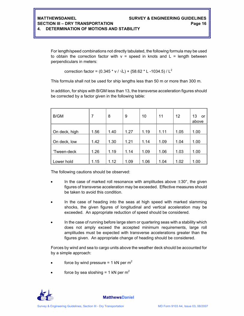
For length/speed combinations not directly tabulated, the following formula may be used to obtain the correction factor with v = speed in knots and L = length between perpendiculars in meters:
correction factor = (0.345 * v / √L) + {58.62 * L -1034.5) / L2
This formula shall not be used for ship lengths less than 50 m or more than 300 m.
In addition, for ships with B/GM less than 13, the transverse acceleration figures should be corrected by a factor given in the following table:
B/GM 7 8 9 10 11 12 13 or above
On deck, high 1.56 1.40 1.27 1.19 1.11 1.05 1.00
On deck, low 1.42 1.30 1.21 1.14 1.09 1.04 1.00
‘Tween-deck 1.26 1.19 1.14 1.09 1.06 1.03 1.00
Lower hold 1.15 1.12 1.09 1.06 1.04 1.02 1.00
The following cautions should be observed:
• In the case of marked roll resonance with amplitudes above :t:30°, the given figures of transverse acceleration may be exceeded. Effective measures should be taken to avoid this condition.
• In the case of heading into the seas at high speed with marked slamming shocks, the given figures of longitudinal and vertical acceleration may be exceeded. An appropriate reduction of speed should be considered.
• In the case of running before large stern or quartering seas with a stability which does not amply exceed the accepted minimum requirements, large roll amplitudes must be expected with transverse accelerations greater than the figures given. An appropriate change of heading should be considered.
Forces by wind and sea to cargo units above the weather deck should be accounted for by a simple approach:
• force by wind pressure = 1 kN per m2
• force by sea sloshing = 1 kN per m2

MATTHEWSDANIEL SURVEY & ENGINEERING GUIDELINES SECTION III – DRY TRANSPORTATION Page 17 4. DETERMINATION OF MOTIONS AND STABILITY
MatthewsDaniel
Survey & Engineering Guidelines, Section III - Dry Transportation MD Form 9103 A4, Issue 03, 08/2007
Sloshing by sea can induce forces much greater than the figure given .above. This figure should be considered as remaining unavoidable after adequate measures to prevent overcoming seas.
Sea sloshing forces need only be applied to a height of deck cargo up to 2 m above the weather deck or hatch top.
For voyages in a restricted area, sea sloshing forces may be neglected.
4.5 Recommendation
Under most circumstances MD recommends that a motion response study be conducted and should calculated motions exceed the values in the above standard or IMO criteria, the larger value is to be utilized.
4.6 Intact Stability
The transverse metacentric height (GM) must be positive, at zero angle of heel.
The range of transverse statical stability is given in the table. Correction to values of GM to allow for free surface effects should be included in this computation.
TYPE INTACT RANGE
Large Vessels 40º
Small Vessels 40º
The acceptability of vessels with a range less than 40 degrees will be dependent on motion response predictions.
When maximum amplitudes of motion for any specific towage are derived from model tests or motion response calculations, the minimum range of static stability shall be not less than 20+ (∅) degrees, where:
∅ = the maximum amplitude of motion in degrees about the axis concerned caused by the design sea state, plus the static angle of inclination from the design wind.
Cargo buoyancy may be considered in computation of stability characteristics provided that the cargo is watertight and can be shown to be effective in terms of tie-down and hydrodynamic loading.
Cargo overhangs should not immerse as a result of heeling in a 15 m/sec wind in still water conditions.
The minimum GM should not be less than 1.0 meter unless it can be shown that the actual GM for the voyage is not less than the calculated positive GM and all other considerations do not prevent that value being approved.

MATTHEWSDANIEL SURVEY & ENGINEERING GUIDELINES SECTION III – DRY TRANSPORTATION Page 18 4. DETERMINATION OF MOTIONS AND STABILITY
MatthewsDaniel
Survey & Engineering Guidelines, Section III - Dry Transportation MD Form 9103 A4, Issue 03, 08/2007
4.7 Dynamic Stability
The area under the righting moment curve to the second intercept of the righting and wind overturning moment curves, or the downflooding angle, whichever is less, shall not be less than 40% in excess of the area under the wind overturning moment curve to the same limiting angle.
Figure 3.1 Wind Heeling Moment Diagram
The wind velocity taken for overturning moment calculations shall be the lesser of the design wind speed or 100 knot. For this purpose, a 1-minute mean wind for the 10-year return extreme condition shall be used for the design wind speed.
4.8 Damaged Stability
It shall be demonstrated that the vessel with cargo will have sufficient reserve buoyancy to remain stable and afloat when any one watertight compartment is flooded. Minimum penetration shall be considered to be 1.5 meters. Two adjacent compartments on the periphery should be considered as one compartment if separated by a horizontal watertight flat. The emptying of a full compartment to the waterline should be considered if it gives a more severe result than flooding of an empty compartment. The ability to compensate for damage incurred, by pumping out or by ballasting other compartments, etc., is not to be considered as alleviating the specified requirements.

MATTHEWSDANIEL SURVEY & ENGINEERING GUIDELINES SECTION III – DRY TRANSPORTATION Page 19 4. DETERMINATION OF MOTIONS AND STABILITY
MatthewsDaniel
Survey & Engineering Guidelines, Section III - Dry Transportation MD Form 9103 A4, Issue 03, 08/2007
The unit is to possess sufficient reserve stability in the damaged condition to withstand the overturning moment of a 50 knot sustained wind superimposed from any direction and meet the following criteria:
• The angle of equilibrium must not exceed 15 degrees after equalization.
• The deck edge may not be submerged at any point.
• The vessel's metacentric height (GM) must be at least 2 inches when the vessel is in the upright position.

MATTHEWSDANIEL SURVEY & ENGINEERING GUIDELINES SECTION III – DRY TRANSPORTATION Page 20 5. GRILLAGE/CRIBBING, SEAFASTENINGS AND CARGO LOADS
MatthewsDaniel
Survey & Engineering Guidelines, Section III - Dry Transportation MD Form 9103 A4, Issue 03, 08/2007
5. GRILLAGE/CRIBBING, SEAFASTENINGS AND CARGO LOADS
5.1 General
The purpose of the grillage and seafastenings is to secure the cargo during the transport so that neither the cargo nor vessel suffers damage as a result of severe environmental conditions or other accidental events.
The grillage/cribbing design and layout should take account of any limitations imposed by the load-out method.
The basis for the design of the grillage, seafastenings and cargo shall be the loads resulting from the methods defined in Section 4 above.
Seafastenings shall be designed to be removed easily without damage to the cargo. During removal of the seafastenings, the cargo shall remain supported and restrained horizontally by the grillage/cribbing.
5.2 Loads During Transportation
The components of load to be considered when analyzing the total forces between the vessel and cargo are those due to:
• Static weight of the cargo and ballast;
• Static heel and trim;
• Dynamic loads which result surge/sway, roll/pitch and heave;
• Wind load;
• Wave induced bending loads;
• Slamming loads;
• Loads resulting from immersion of any part of the cargo.
The combination of motions, which give the highest loading in any direction, shall be considered using the following combinations.
• Roll, heave and sway
• Pitch, heave and surge
Alternatively, results of a motion analysis taking account of phase relationships between motions to compute acceleration vectors may be used.
The benefits of free surface should not be taken into account in the calculation of motions unless this has been specifically model tested.

MATTHEWSDANIEL SURVEY & ENGINEERING GUIDELINES SECTION III – DRY TRANSPORTATION Page 21 5. GRILLAGE/CRIBBING, SEAFASTENINGS AND CARGO LOADS
MatthewsDaniel
Survey & Engineering Guidelines, Section III - Dry Transportation MD Form 9103 A4, Issue 03, 08/2007
Account shall also be taken of any significant loads in the grillage and seafastenings resulting from the relative deflections of the transport vessel and cargo, resulting from ballast changes or due to environmental effects.
5.3 Grillage and Seafastening Strength
The grillage and seafastenings shall be designed such that the static stresses in all members do not exceed the allowable stresses.
Seafastenings shall be designed to accept anticipated deflections of the vessel in a seaway. For cargoes that will be delivered offshore, the seafastenings should be designed to be released in stages. The final stage of seafastening should be determined for the particular project, however, the ability of the cargo to resist a 10 degree static angle is a good rule-of-thumb.
If seafastening design stresses are high, non-destructive examination may be recommended in an agreed manner particularly in critical areas where the allowable stresses are high using the 1/3 increase in allowable stresses. The amount of NDE should be agreed with the MD Surveyor on site but may typically amount from 20-50% of the critical welds.
The maximum friction coefficient that may be used when the cargo is stowed on wood cribbing is a percentage of the weight based on cargo mass and cargo overhang as seen below in Figure 5.1 unless provided with acceptable supporting documentation (taking the maximum vertical acceleration into account). The formula to determine maximum cribbing friction is:
Friction = friction coefficient x cargo weight x (1.0 – max.acc.vertical)
Where: friction coefficient from Figure 5.1
cargo weight in [metric tonnes]
max.accvertical in [g]

MATTHEWSDANIEL SURVEY & ENGINEERING GUIDELINES SECTION III – DRY TRANSPORTATION Page 22 5. GRILLAGE/CRIBBING, SEAFASTENINGS AND CARGO LOADS
MatthewsDaniel
Survey & Engineering Guidelines, Section III - Dry Transportation MD Form 9103 A4, Issue 03, 08/2007
Figure 5.1 Friction Coefficients

MATTHEWSDANIEL SURVEY & ENGINEERING GUIDELINES SECTION III – DRY TRANSPORTATION Page 23 5. GRILLAGE/CRIBBING, SEAFASTENINGS AND CARGO LOADS
MatthewsDaniel
Survey & Engineering Guidelines, Section III - Dry Transportation MD Form 9103 A4, Issue 03, 08/2007
Figure 5.1 Friction Coefficients
Including the friction reduction, the minimum seafastening capacity should never be less than:
2.5 % of cargo weight in longitudinal direction
10.0 % of cargo weight in transverse direction
When uplift is calculated due to overturning moments caused by motions and/or wind loads and/or buoyancy loads by submerged water, effective countermeasures are required either in ensuring avoidance of such loads, or applying uplift lashing in the seafastening concept.

MATTHEWSDANIEL SURVEY & ENGINEERING GUIDELINES SECTION III – DRY TRANSPORTATION Page 24 5. GRILLAGE/CRIBBING, SEAFASTENINGS AND CARGO LOADS
MatthewsDaniel
Survey & Engineering Guidelines, Section III - Dry Transportation MD Form 9103 A4, Issue 03, 08/2007
5.4 Transport Vessel and Cargo Strength
For the transport vessel the calculated still water bending moment and shear force shall be checked against the allowable values approved by the Classification Society.
The cargo structure (including the legs, hull jack houses of jack-up units) is to be checked for the loads imposed during the transport combined with any additional loads caused by overhang.
The cargo should be shown to have adequate strength to withstand the seafastening loads, and it should be shown that the effect of support on the cribbing arrangements will be within the structural capability of the cargo.
Legs on jack-ups are to be secured against horizontal movement by means of shimming, or by use of an approved locking device, or by other appropriate means to ensure that shock loads are avoided.
Major sub-structures including drilling sub-structures and derricks shall be demonstrated to be within the requirements of the motion to be imposed by the transport.
Cargo overhangs should not immerse from wind heeling from a 15 m/sec wind in still water conditions without further detailed consideration. Cargo overhangs being occasionally immersed and which may receive wave slam loadings will require special consideration. Local wave loading on the cargo should be investigated to establish that no structural damage will occur.
Fatigue on cargo is generally not considered to be the role of the warranty surveyor, however, M-D will undertake such a study if requested.
5.5 Internal Seafastenings
Internal seafastenings shall be provided where necessary to prevent damage to equipment or loose items forming part of the cargo. Protection against wave slam or spray should also be provided as appropriate.
For major items of equipment, calculations may be required. In other cases the requirements for and suitability of internal seafastening may be agreed with the attending MD Warranty Surveyor.
5.6 Cribbing
Sufficient cribbing is to be provided to give an adequate load distribution on the bottom of the cargo.
Appropriate clearance should be present between the cargo and the ship to allow for water runoff – a general rule of thumb is 2".

MATTHEWSDANIEL SURVEY & ENGINEERING GUIDELINES SECTION III – DRY TRANSPORTATION Page 25 5. GRILLAGE/CRIBBING, SEAFASTENINGS AND CARGO LOADS
MatthewsDaniel
Survey & Engineering Guidelines, Section III - Dry Transportation MD Form 9103 A4, Issue 03, 08/2007
The normal static pressure on the cribbing should not exceed 150 psi for softwoods with a max combined static + dynamic pressure of 450 psi. Cribbing pressures can be higher provided it can be shown that this is not overstressing the cargo, cribbing or the vessel and approval has been obtained from MD-Houston engineering department.
In the case of a random or non bulkhead specific cribbing layout the maximum static plus dynamic cribbing pressures should not exceed 200 psi, subject to consideration of the overall loadings on the vessel deck and underside of the cargo.
The cribbing should be designed as a minimum to withstand loads caused by any trim or heel angles during on-load and off-load. If no other criteria applies, a minimum angle of 5º should be used.
5.7 Cargo Protection
All cargo shall be protected from wave slam and wetting damage as appropriate. This may require provision of breakwaters or waterproofing sensitive areas.

MATTHEWSDANIEL SURVEY & ENGINEERING GUIDELINES SECTION III – DRY TRANSPORTATION Page 26 6. OPERATIONAL ASPECTS
MatthewsDaniel
Survey & Engineering Guidelines, Section III - Dry Transportation MD Form 9103 A4, Issue 03, 08/2007
6. OPERATIONAL ASPECTS
6.1 Pre-Sailaway Checks
Prior to the issue of the Certificate of Approval for the sailaway, all parties shall be satisfied that the transport vessel is ready for departure.
Particular attention shall be paid to the following:
• Security clearance papers;
• Vessel documentation including classification;
• External and internal seafastenings - completion and satisfactory NDE checks;
• Load spreading devices (grillages/cribbing) in place;
• Watertight integrity of transport vessel;
• Fuel supplies sufficient and re-fuelling ports identified;
• Loose gear tied down.
The attending MD warranty surveyor may make further recommendations.
6.2 Transport Vessel Routes
The transport vessel route shall be proposed by the transport contractor for acceptance by all parties. In selecting the route, the following items shall be taken into consideration:
• Navigation through restricted passages including departure and delivery locations;
• Emergency shelter areas/ports of refuge;
• Likely weather and sea state en route.
The route selected shall have adequate bottom and side clearance for the transport, the parameters being dependent on the accuracy of navigation and the size and draft of the transportation vessel.

MATTHEWSDANIEL SURVEY & ENGINEERING GUIDELINES SECTION III – DRY TRANSPORTATION Page 27 6. OPERATIONAL ASPECTS
MatthewsDaniel
Survey & Engineering Guidelines, Section III - Dry Transportation MD Form 9103 A4, Issue 03, 08/2007
6.3 Communication and Reporting
The Master should be fully briefed on all aspects of any cargo transportation limitations.
The Master shall report each 24 hours the following information:
• Position and time (GMT);
• Situation report, including weather, sea state and speed through water;
• Anticipated situation for the next 24 hrs;
• Sailed distance during the previous 24 hours;
• Any observations with respect to the cargo:
• Damage observed;
• Boarding parties check;
• Expected time of arrival (ETA).
If any emergency situation occurs the MD warranty surveyor and MD Houston Office shall be informed as soon as possible.

MATTHEWSDANIEL SURVEY & ENGINEERING GUIDELINES SECTION III – DRY TRANSPORTATION Page 28 7. REQUIREMENTS FOR TRANSPORT VESSELS
MatthewsDaniel
Survey & Engineering Guidelines, Section III - Dry Transportation MD Form 9103 A4, Issue 03, 08/2007
7. REQUIREMENTS FOR TRANSPORT VESSELS
7.1 General
The proposed transport vessel shall be inspected by an MD surveyor and approval given subject to its condition and the condition and suitability of the vessel and machinery. Documentation required by the flag state and international convention, and class certificates shall be in order.
7.2 Documentation
Most transportations are subject to approval from national and local regulatory bodies in particular with regard to the safety of personnel, security and environment.
So far as practicable MD surveyors will check the validity of the appropriate documentation and highlight any areas, which come to the attention of the surveyors, accepting the fact that this is a specialist activity and not the general role of the marine warranty surveyor.
The following documentation should be available on the vessel for any transportation:
a) Certificate of Class issued by a recognized classification society;
b) Certificate of Registry;
c) Tonnage Certificate (if not incorporated in other certification) (determines port dues);
d) Certificate/Approval of navigation lights and shapes issued by a recognized authority;
e) International Load Line Certificate;
f) Documents required for the outward clearance at the port of departure and for inward clearance at the port of arrival to be made available for sighting by the attending surveyor. These include clearance by customs, agriculture, health and other regulatory bodies. Troublesome points, on occasion are the importing of cribbing wood, and seafastening steel, which may need special arrangements;
g) Deratization Certificate, or exemption if applicable (some Health Authorities require);
h) MD Certificate of Approval for a particular transportation (issued on sailing);
Note: The Marine Warranty Surveyor does not cover items in the charterer’s interest such as suitability inspection and on-hire survey of the vessel, both of which should be carried out prior to acceptance by contracting parties.

MATTHEWSDANIEL SURVEY & ENGINEERING GUIDELINES SECTION III – DRY TRANSPORTATION Page 29 7. REQUIREMENTS FOR TRANSPORT VESSEL
MatthewsDaniel
Survey & Engineering Guidelines, Section III - Dry Transportation MD Form 9103 A4, Issue 03, 08/2007
7.3 Technical Information
The Contractor should supply the following particulars of the transport vessel proposed for transportation:
• General Arrangement drawings;
• Deck load capacity plans for point loads and uniformly distributed loads;
• Typical midship and longitudinal sections if required for evaluation of structural strength;
• Ballast capacity plan;
• Stability data.
If a compressed air ballasting system is fitted, full details shall be provided.
7.4 Ballast and Pumping Systems
Ballast pumps of suitable design and capacity shall be provided on the transport vessel for the following:
• General ballasting and deballasting operations including during and after load-outs;
• Correction of draft or trim in normal operations and after discharge (especially at sea);
• Damage control and counter flooding purposes in event of hull damage, grounding etc.;
• Deballasting to reduce draft to enter port;
• Trimming to allow inspection and repair below normal waterline;
• Access to a flooded compartment.
7.5 Regulatory Matters
For self-propelled dry transportation a number of matters are part of the vessel’s responsibility and regulations imposed by normal marine practice will be notified if observed by the MD surveyor. These items include:
• Navigation Lights and Shapes;
• Manning.

MATTHEWSDANIEL SURVEY & ENGINEERING GUIDELINES SECTION III – DRY TRANSPORTATION Page 30 7. REQUIREMENTS FOR TRANSPORT VESSEL
MatthewsDaniel
Survey & Engineering Guidelines, Section III - Dry Transportation MD Form 9103 A4, Issue 03, 08/2007
7.6 Manning
If the cargo is manned, the crew should be registered as part of the ship’s crew or special provisions made to be under the direction of the Master of the transport vessel.
The crew should be organised into a watch keeping system to ensure a continuous monitoring of conditions on board. They should be familiar with the equipment and cargo and make frequent inspections.
A transport vessel log should be kept giving:
• Wind and sea conditions;
• Motions;
• Anything unusual, which should be reported.
Suitable accommodation shall be provided with facilities for watch keeping, communications, and cooking, sleeping and sanitary requirements for the cargo if manned. These may be subject to national and local regulations.
Lifesaving and fire fighting equipment shall be carried in accordance with international and national regulations for the safety of the number of people carried. The lifesaving and fire fighting equipment shall be documented.
The decks and access ways should be adequately lit but such lighting should not interfere with or be liable to be confused with navigation lights.


![[PPT]Grillage Analysis for Slab & Pseudo-Slab Bridge Decksenggprog.com/Downloads/Lectures/BridgeEngg/Lecture No. 3... · Web viewTitle Grillage Analysis for Slab & Pseudo-Slab Bridge](https://img.pdfslide.us/doc/110x75/5adedacf7f8b9afd1a8beaa6/pptgrillage-analysis-for-slab-pseudo-slab-bridge-no-3web-viewtitle-grillage.jpg)