Embed Size (px)
DESCRIPTION
Log book final submission The University of Melbourne
Citation preview
ffiTT{[ t'NIVILIITY OT
The University of Melbourne
Environments & Design Student Centre
Ground Floor of the Baldwin Spencer Building
ilIltI|l I ll I IIIIllIilIIIllillIlll]Illlil ll0039360000000002 1 885 1
MTLBOURNE
ASSIGNMENT COVER SHEETThis form must be attached to all submitted written work with all sections completed to the Environments &
Design Student Centre, Ground Floor of the Baldwin Spencer Building. An incomplete form may result in thedelayed return of your assignment or of your mark for the assignment. Please keep a copy of all assignmentsbefore submitting them for assessment.
Subject Code: ENVSl0003 2014-SM1Subject Name: ConstructingEnvironments
Student lD Numberi 698447Student Name: Matthew Johnfhompson
Tutorial= T20
Assignment Name: A01 LOGBOOK FINAL SUBMISSION (all studio sessions)
Assignment Due Date: May 19 2014 at 01:00 PM
Plagiarism is the act of representing as one's own original work the creative works of another, without appropriate
acknowledgment of the author or source.
CollusionCollusion is the presentation by a student of an assignment as his or her own which is in fact the result in whole or in part
of unauthorised collaboration with another person or persons. Collusion involves the cooperation of two or more students in
plagiarism or other forms of academic misconduct.
Both collusion and plagiarism can occur in group work. For examples of plagiarism, collusion and academic misconduct in
group work please see the University's policy on Academic Honesty and Plagiarism.
plagiarism and collusion constitute cheating. Disciplinary action will be taken against students who engage in plagiarism
and collusion as outlined in University policy. Proven involvement in plagiarism or collusion may be recorded on my '
academic file in accordance with Statute 13.1.18.
STUDENT DECLARATIONPlease tick to indicate that you understand the following statements:I declare that this assignment is my own original work, except where I have appropriately cited the original source.This assignment has not previously been submitted for assessment in this or any other subject.
For the purposes of assessment, I give the assessor of this assignment the permission to:
tr Reproduce this assignment and provide a copy to another member of staff; and
l={ take steps to authenticate the assignment, including communicating a copy of this assignment to a checkingEJ service (which may retain a copy of the assignment on its database for future plagiarism checking).
Student Signature: Date la los I [*

a
Constructins environments log book
Week 1: Block Tower Conitruction
Building a stable structure using compression force was carried out in the tutorial- The use of M.D.F
(Medium Density Fibre-board) allowed for easy construction as its lightweight structure made the
placement of the blocks an easy task. The structure of the tower (as shown) is a rectangular based
formation with gaps between each building block to allow great counter wait forces to be applied to
each block. This would assist the later process of excavation when creating an arch
doorway/entrance to the structure.
As shown, the two blocks situated underneath a particular block share the
base load as denoted by the arrows in this picture. This idea was to assist in
the prevention of collapse when block were removed from the structure
using the comPression theory.
An ldentical trend was continued until a development of the structure could
be noticed. Due to time constraints, the height of the tower was not to the
endeavoured feat. However the practicality of the process was still shown-
Due to the downward force being placed upon successive block, it granted
the easy removal of a specific section of the structure. However the stability
of the doorway decreased dramatically as more blocks were removed- This
could be attributed to the reduction of raw materials which contributes to
the weight force which reaches a threshold to enable the build to remain
erect.
By executing this theory we were successfully able to construct a structure
large enough to facilitate the dinosaur, thus the aim of the exercise
successfully achieved.

The method of first building the structure then excavating at a single side to form a doorway proved
more successfulthan building a doorway from the beginning of construction. This was due to the
load force already present in the structure, acting on subsequent individual block pieces below a
particular piece. This means that building a doonnray from the start was more difficult as the
compression force being applied from above was absent, as shown:
n "$4 ff[k'^fuEY_-
ele?rning Summarv and Glossarv
Materials are selected for certain constructions due to the.following criteria:
Strength
Stiffness
Shape (Mono-dimensional, Planar, Volumetric)
Material Behaviours (lsotropic, anisotropic)
Economy
Sustainability
Landscape is a fundamental background to the constructive citY. ln the case of Melbourne, basaltic
rock surrounded the landscape and indicated Melbourne's volcanic history. Bluestone is a material
that was selected from the economic category listed above. Being a local material, it was more cost
effective to take advantage of the local landscape for building structures. This decision has become
iconic to the city of Melbourne, giving the city its dark colour. As far as sustainability, it is logical to
use local materials, as less energy is required in the production and transportation of the rock. This
ultimately possesses a lesser environmental effect compared to the alternate building materials.
The history of the city can be seen through the damage to the bluestone. Damage such as wheel
ruts where the carriageways of the 19s century have left lasting effects on the structure. Others
methods of damage include water damage and impact damage from heavy vehicles.
Load path diagrams indicate that a particular applied load, whether it be dead or live, will be
distributed on the most direct route down to the ground where a reaction force will come in contact
with the structure at an equal and opposite amount to the applied load.
a
a
a
a
a
a

Glossary
Force - a force is any influence that produces change in the shape or movement of a body. Basic
structural forces include tension and compression
Load path - The direction in which consecutive load will pass through connected members. For
example, a dead load being distributed down particular structure of the building
Point loads- a load that is localized to a specific location of the structure
Static loads -loads that are assumed to be applied slowly until it reaches its peak value withoutfluctuating magnitude or position
Live loads - comprise of any moving or movable loads on a structure. Typically acts vertically
downward
Occupanry loads - loads resulting in the weight of people, furniture, stored material, and othersimilar items in a building.
Snow loads- as a result of snow accumulating on the roof of the building
Rain loads-as a result of rain accumulating on the roof of the building
Dead loads - static loads acting vertically downward on a structure
lmpact loads- kinetic loads of short duration due to vehicles, equipment, and machinery
Dynamic loads- loads that are applied suddenly to a structure, often with rapid changes in
magnitude and point of application
Wind loads- forces that are exerted by the kinetic energy of a moving mass of air, assumed to come
from any horizontal direction
Masonry - The process of constructing buildings or structures with individual units held together by
mortar.
Reaction force- an opposing force
lsotropic- a materialthat displays simiiar characteristics regardless of which direction the force is
applied
lecture 1: Absent due to timetable clash
The lecture aimed to explore the idea of spreading the base load of an object. This was accomplished
by folding 1 sheet of paper such that it would spread the weight force applied by a single brick.

ua{i
\*= s
'c3,4ge',?
$g?lF ),;
nr,- ne t, "i 3t '*'lt', ,3i
le 'FT{*{,t ;;11'
xt? I )i&A 'g,i',:=' 4d\-\ {) bj' ;u* | &1
A\* \11 ' f=l rP
a-it \ [ / 3{ffn.,\)/ abt--\1 ilill fi*t i 1
E f 1r* , |3.F. !-Iii .r
4/ / \ t- | \ Vl ? r€ / \ \T |qL, 7,,
{* y/ *,P'*-'
.lT\X} qa-"gf{ai*
.-,itrrrrt
q." Y ie{1 tti 3--A*
EI?
ftatJ
o-li
'j.)
eo9,yC

Week 2: Balsa wood frame construction
Using the idea of triangles in conjunction with part-by-part assembly, the construction of our frame
occurred in stages, and came together as a single structure almost instantaneously.
Through logicalthinking, it was decided that the tower would
need to become narrower in sections in order for the base to
support the load above. Therefore it was calculated that
equilateral triangles of side length 30cm should be constructed
in order to support the applied force which would eventually be
supported by the base.
This is an example of our "part production" method. The length
of the prism was 60cm. Although this didn't seem stable at the
time, extra triangle braces were added in a uniform pattern togrant the frame structure extra strength. This would assist in
Ioad distribution and stability of the structure as it expands in
height.
The tower was formed through a series of fixed joints held
together at a particular point. This often made it hard to
construct a straight, structurally sound tower. This was because
the fixed joints caused bending as either a result of
miscalculated lengths of balsa or an angle that was not identical
to the other braces being formed with the base.
The bending can be seen in this picture as indicated.
The base section showed no sign of bending before the second
section was applied. This may be attributed to an applied load
(above) being applied to this particular member, causing a
bending at the joint
Furthermore, the pieces of balsa were in some cases were not
straight lines and in particular places, had quite severe bends
from the cutting process.
Extra bracing was also added in attempt to negate this bending
that was observed.

Structure load Path & desien idea
pictured is a smaller based pyramid, which connects to the top
ofthe structure shown above and brings aboutthe peak ofthe
structure. The smaller triangle added to the middle of the frame
was purely to increase the stability of the structure without
applying a heavy weight force to the peak of the structure'
The final structure was just short of the ceiling, as we attached a
straight piece of balsa, mocking structure such as the empire
state building to increase height
The arrows denote signs of structural instability, as there was
sever bending in many places of the frame structure' This is
once again attributed to the fact that the structure contains
fixed joints and a compression force is being applied on top (the
above frame) resulting in bending.
Many other groups where unsuccessful in building their
structure. lt seemed that a common factor was a squared based
building. lt seemed that not enough materials were supplied to
successfully frame a square stable structure'
LD toaA S**Da=rqv\:t**
- 5\ooA ,Q*'$\^&
- g0en^ \cOse QrytStnr.L
.s) B0r-s.\ \oq*g a)r onr''
aiA \o !9onn q-\
a AOcvYr tQp*'?4
O,^.raaariA \O
'i".L -\ W
Aeerr. arr co.lco\*"A wi[t^*,.

elearning Summarv and GlossarY
Structural systems can be categorised into solid, shell, surface, frame, skeletal, membrane and
hybrid systems.
Construction systems can be categorised into enclosure, structural and service systems. The choice
behind each category is based on performance requirements, aesthetic qualities, economic
efficiencies, environmental impacts and also the construction context as a whole. When building a
structure, both the initial cost and life rycle costing of the building. This includes the longevity of the
building and its ability to act as a filter, maintaining comfort without the need of electrical appliances
(eg. Air conditioning).
Ecologically sustainable design is the conscious effort to reduce the environmental impact when
cons$ucting new buildings or infrastructure. Common strategies include:
o Local materials
r Materialefficiencyo Thermal mass
o Night air purging
o Solar energy
o Wind energy
o Cross ventilation
o Smart sun design
o lnsulation
o Water harvesting
Certain materials require certain amount energy in order to be produced. This must be taken into
account when choosing particular materials in reference to their respective carbon footprint.
Glossary
Carbon footprint- a measure of the amount of greenhouse gases generated during the fabrication,
transportation and use of a particular product
Embodied energy- is the total energy used during all stages of a material's life.
Life Cycle- from the beginning to the end of a particular material in a specific process
StructuralJoint- can be classified as either roller, pin or a fixed joint.
Bracing- added support to brace a structure
Column- a supporting pillar, generally found to be under some sort of compression force.

lecture ?
lnvestigated the framing process using an example of the 'watertanK.
The knowledge from the lecture was taken into our studio session
as it was decided that a triangular shaped frame would possess
higher stability than that of a square base structure. This was
shown as a variety of triangle framed water tanks tested a higher
resistance to an applied forced than other attempts.
Load capacity was increased when supplied with more pins and
straws for the exercise. Some strategies included:
o Use of two pins, result in stronger structural joint connections
o Triangulation (our chosen method) of posts
r Extra bracing between posts
o Larger footing, increase load distribution at ground level
o Shortening post length, structure closerto ground level
Some strategies were more successfulthan others and this was noted and executed when building
the balsa wood tower. Triangulation proved the most successful, however without extra bracing
between posts, this may not have been enough support forthe structure. lt appears that to have a
successfu! structure you must use a collaboration of the above techniques without compromising
efficiency of materials.

Week 3
Tutorial
The aim of this weeKs studio session was to examine real life examples of the theory that was learnt
in the elearning. A tour was conducted around the university to identify different structural
elements and also in particular, different characteristics of masonry construction.
Here is an example of the use of pre-cast concrete as
structure members of a structural environment. The reason
behind the use of pre-cast is that it makes the speed of
construction faster and more efficient as they can be put in
place with ease, rather than constructing each individual
member on site.
The bond of masonry was heavily focused on in this session. lt
was highlighted in structures around the university, and thus
became easy to distinguish different patterns over the course
of the tour.
@Strrchh+v
@!Ro,^r\o&
Ahrelrche.rz
,*" o*"#"**r":rrff
HcoarY
#ffioour\o& soi\""'
Sovvce: lau\c'id*irgrr& -*3 /nP'e/tts*"ebl ctir"daoJe/kuc\h'r{t//€eil"il^co'ltmlu
Examples of different pre-construction designs were shown.
The pylons for the Melbourne University Car Park form areas
in which above, trees are planted. This helps with drainage
and water efficiency of the area. Each pylon is positioned
within the vicinity of trees or gardens. Concrete was used in this case for its easy in modifying its
shape to one which is desired for the design.
The importance of designing and planning before going ahead with construction was very much
emphasized in this example, with the idea of the future and sustainability in mind.

The steel structural members of this staircase at Union
House form an "optical illusion" in terms of the members
that are actually load bearing. The member indicated by
the arrow carries very minimal load as the structure was
designed to form this effect.
Steel cable is used to suspend the beams under the stairs,
which are under tension from the weight forced of the
structural member
The load is taken directly to the ground where it is met
with an equal but opposing reaction force, as shown here.
Another parallel beam to the one seen above is supported
by two columns, which are under heavy compression
force.
The structural joints present are fixed joints at the bottom
ofthe staircase, and the beam connecting to the stair
framing.
An example of sandstone block masonry
was observed at the arts west building. A
difference in materials was frequently made
between this building and other buildings,
which were formed from pre cast concrete.
The use of sandstone, a sedimentary rock,
masonry gives an aesthetic property to the
building, which is not achieved by concrete.
Also, Limestone is very frequently used in a
similar way.
Glossarv
Moment- The moment of a force is the tendancy to make an object or point rotate (Moment= Force.
x Distance)
Retaining wall- are used when sites are excavated to create basements, holds back earth from falling
into the already excavated area.
Strip Footing-Used when loads from a wall or series of columns is spread in a linear manner.
Pad footing- also called isolated footings, these type of footings help spread a point load over a
wider area
Substructure- Foundations are the substructure, their function is to transfer all loads acting on the
building to the ground

elearning and Lectures
Lecture-
London was compared to Barcelona, however there needed to be use for the site after the gamesconcluded. The wellbeing of the people was heavily considered in the construction of the Olympicpark, which catalysed a central (middle) park to be heavily utilized at the conclusion of the games.Problems with soil quality arose in the early development of the infrastructure. The large cost intransport the soil was one issue, but the main contributor being it was heavily polluted.
Engineers needed to treat the soil with the following steps7. Remediation2. Wash3. Sieve
4. Shake5. Removed oil, gas, tar, cyanide, carsenic as a result
Groundwater was treated by injecting compound into the soil, which generated oxygen.
Problems occurred with housing in that the need for evolution of the space after the athletes leftwas a difficult to manage process. lmportance of legary was heavily emphasized, being that theremust sustainable/usable area left for the English people in the future.The garden/park,s Landscapewas productive, seasonal and efficient. Rubber infill that was in the area was removed to revealfootbridges after the games completion. Further giving th9 site purpose.
Stadium was located on an island separated from other parts of the olympic province. The stadiumwas considered to be a contributor to the legacy of the site, potentially used after games by asoccer team at the games conclusion (Westham FC).
The Stadium was considered as a theatre in the building process as wetl as a home for sport.Theacoustics were achieve by the stadium being buried low in the ground.
o 80,000 capacity
o 25,000 ground capacity and 55,000 in the frame structure
A decision was made to change to light steel cable netting which consequently used 1000 tonnesless steel. The canal system was used to transport mass and building materials as it has been forgenerations before. This represents the efficiency that this system possessed even centuries ago.Compared to Beijing London used 8x less carbon and a% of the steel making it a far moresustainable Olympics. Furthermore, the swimming pools were reused in high schools, meaning thewaste of materials was significantly reduced.

Figure: Range of mortar finishes and The Australian standard measurements for a
single brick unit

,3tH0
4,d
BT;949
s ttg t ;$e i--,=,*L tiV Y$,f"4Pg1E ;i jd ,FHAr$* i3r E \Egq5:;t/ T1;'*Lnij
I c o . e..o 9
"
#,E&s+€gs&i\ tur 'l\ {-r\ e^,?
r {q:tHi* /FE, t;t-:tt' {s ilL{a ;5S t@/:a o-L
W Tli
Eq$,^-7,4 Q
; i,,1ie?'i3;;B#te
9- 9'"<') fro\
€l=B3t83-6\
=?oE
o
n5I
??D(T3
6,)o€
/
{s$.i.:
. i E B
ti it!3 ,
't ) b t:iBq')'.,i 5""''jrli{ttL3 3 A c ? $'E..o!"oUq
\tt*o)toJt
p\U\
%dlnlzl)
da
lsi%s
rlS .->d +.0Eo
I/
.*S
E
#+
i{ZLo-,*
5e2A)
gtE){2
dS/od
ffr{&iLY?B
g8U3Io+s
'{t.
re
&Iz{3o,B7
,g,lda?95)3i
6.E
es:$,3''9.
sd;) .?*t
a
I5)OJi
<f)
IBreCJ

{3 .'g-)d 5 S=5 e s:s* b: ,i€a 'tF +a o
=j tr 3r11 *a Y{-{ xtR ta-ets- Bg1 ., 11e-), g tsj1*.t- B ; v
Jg<fgr
Btl" fi<e,'QJ6ag$2
,P4:J*i
H ;e*
-;g €r,$-t: g
(
TE()
+Et4ga
l-P
II
IJ
h$
)-P(,J
*
E-<a)
1€)*\n
ntr2A-2-t \'rU
691)4rhb ./"\/
grL,Y,h
,A
&
?qai
hil't:,tI_!.i o r
e?it
4")'B,3-t=
r/l,&
f),2'asB
AJ
7. t,
3 i3*\ \/\g
x&__nn*t %
er (\E"<* \w\=t- --?
&

Week 4
TutorialThis tutorial main objective was to understand the concept and importance ofscale when it comes to construction. The idea of why and how scale is importantwhen designing/planning construction was heavily discussed.Scale is important in drawings, as it allows the architect to accurately measurelife size materials and structural interactions, on a relatively small, easy to workwith piece of paper. However, in order for this process to worh everymeasurement and detail must be exact as the factor in which you multiply yourmeasurements on paper to get "real life" size, may incur large errors.
Preferred working units were those with known standard sizes, for examplebricks or standard timber sizes. These allow the ease in calculation of the lengthof particular members of the structure. Appropriate common architectural scales
were decided to be 1:L, 1:10, and 1:20. These numbers are very easy to convertmeasurements to either side of the scale.
A questionnaire was undertaken regarding the Oval Pavilion, which is currentlyunder construction. This raised the question surrounding design and plans,
elevations in drawings, sections and drawing detailing.
elearnins and Lectures
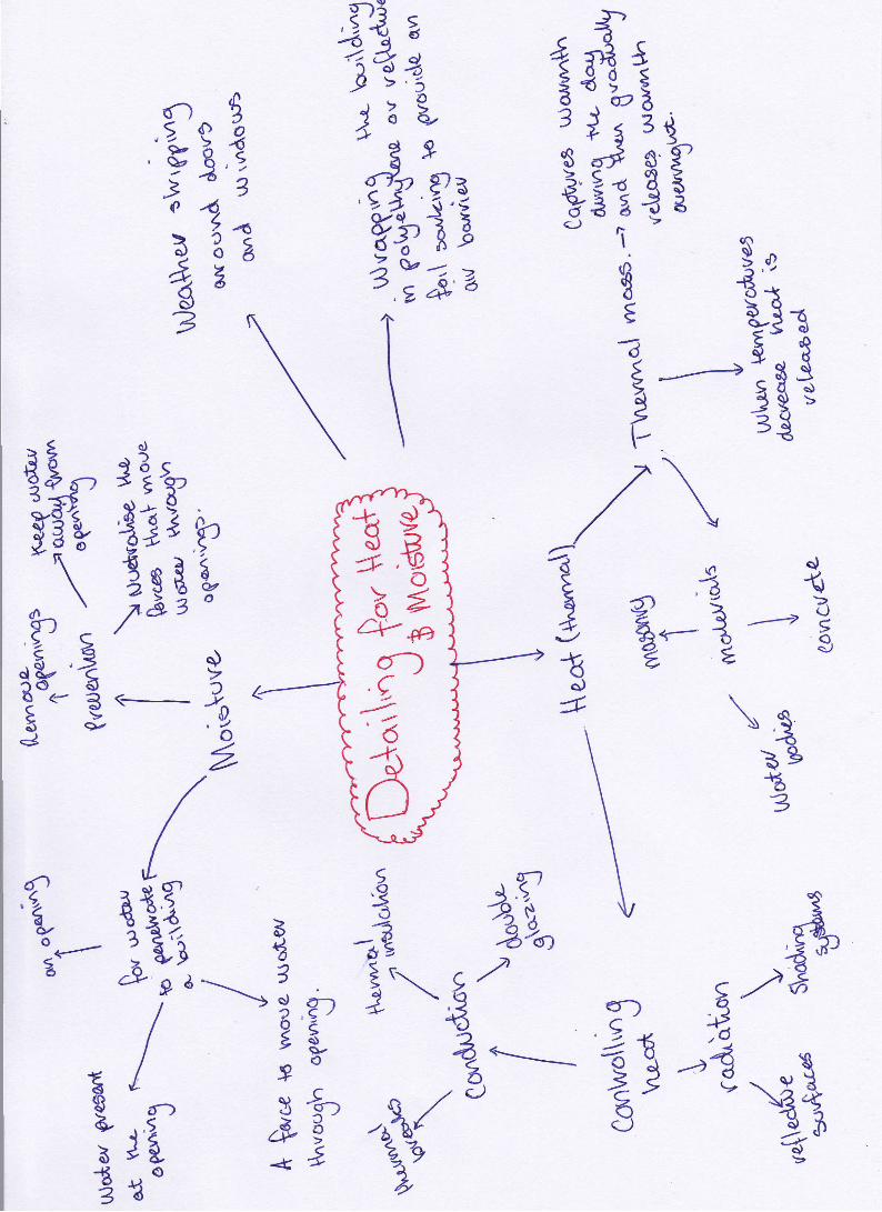
Lecture:The Oval Pavilion was the focus of this lecture. The main focuses of the lecturewere to explore:
. Planning and organisation involved
. The way cultural diversity impacted on the structure, reflects differentbackgrounds
. Engineering
. Architecture
. Technology used for design
. Communication
These ideas are shown in the following mind map.

{
tg-gil a;;igr---
";A$€ 3g' trrry3r - B.ila,? E ''#r",
E c'?'T'"-3+\36 i zia El
tl"ItuE"V 3'/'s9 3 s -rY'4i q\d\ .D \G( a \
6ll>-d
r1l a\"=an
Hg*oYr g gd >/-1\ ss E\E\.E
e-so
€dsq,,o
s):d
1\\)
.S
€\J*+s
-)\)\\,?
-
€&€€t ss
{be')
Bg?
e+i\i
4c)r"iq)
G6a)3
-8.€<r) .t B'ir' gEt 'fg-. -9 sl\ -v -1 .tsg\t--,g3Y's ^ {
-OOI 6U.Ol
o-oI
,z It,str
g"9-'aatp"vt3
\f)n
.)s_dE,-)Jd€
I,9/.
eG
df
iIfl
,l's/uici:lE/EIot"l
\\
%,9t3d9,/?uJ
?46ByeT
*'{k
Ioa
5-4t'39n

elearuing
&#atfism{3SrG'&retfntf,ryrm*okruf,a.SfI06E
Figure: Examples of spacing of different membersand span distance
GlossarvAAarSefumQ#tl6'&t{&t6€o*r**ftn**d",5jiffi
]oist- a horizontal member that runs between at least two supports in order tocarry the load of a ceiling or floor
Steel decking- the decking seryes as a working platform during construction andas formwork for an in situ concrete slab
Span- the distance measured between two structural supports
Girder- a type ofsupport beam
Spacing- the rep6ating distance between a series of like or similar elements,measured centre to centre.

iii3{7;+ X L-gi: iI>3
i1 q\n [r ]qt rttT'? t'$4+t''
Euo ? J\D-o;5
.+sES=5 0SED 5)s+rP
\/g eEt- :,8o,,f'*s
L,g s
E 3)+€)
\/i)
:&(p)oB
c)
-sd[r\
'9*0o??33g?
\t)EAJ6g)
9)E
t)-
\)Isg
slo3?
$
aa9s)o-SJr{-:.,
*'{
4eY,a< g
s,-/ tlJ rl-rOo *EtoPJ
#ea
s)s)
el)
t<+*s4-e3r-- gf t
iB\A?€\8.
J-
,9
eo 5Jl
i:l it /H5T; \€isl e,"%'e io A€ 3 t'
Er3 f,

6d€sJPia
t)Aui, ,t $
E - ,€*'tiq ,r,s
i?1+1ftr13r?zB*€ Lya'"*OG.aaaa
I')t n*{8d.q&
5'_1
L)
s { js
E E}.--> d
* E.ddeJ ('f,3pB€sssLod 9+t,:sHn SslrsJ9 <<
\ <& 6
d
tJ€{
tE =tE"# fl*?
Be ifirt qt* 3282E 31.*eB\o€\€ g
&& ?oS 3€?C'8'a' 2 r. (
gH5,a
frolqJ
&.EoJ'cl
d+{q,
r)9oO
*()d(,s)
o-
3,iX5'd U {
{ tt?v\p
a'?,BtIo:t(?:
$iA B-t$ e;3a (5.)\34o.)I *l{L3h3{fEgsg
**4 \2? e,,--\W
---+ ry) , .o;!
;*E?a\{ -rfl, 3 ,8SI i.rj, q+5
\,?YS
., .<PrO-2
az
S9,aCJ*
Bsa)
9-Eos.,)
J{,Yrc)eo
q)
B46
s.)
E-9.d
Iqit
vtgr,f-9
9)(]r)
7#,: 'd2A'\
,Pts,i'- 8{3$e's 9-c
eB*€6oo(tf
\\
(?,S)J
c)vod
,\1a. ,/ Zi;EaY P#-,fr!2&34,

Week 5
TutorialIn this tutorial we constructed a scale model of the Oval Pavilion using materialsand bonding agent ofour choosing. Our group decided that cardboard and paperwith strong superglue would provide strong structure members as well as theease of working and shaping the sections we needed.
As the cardboard did not have a large surface areat the end of each piece we cut to size, the glue wasnot setting in place fast or securely enough.
Thus, as a management strategy, the group usedpaper pieces to which the glue was applied, andplaced at the joints of each structural member.
This largely improved the stability of the structureand allowed the construction to occur much moreefficiently.
Due to time constraints, the wall that the roofelements connect to in the real life structure wasmodelled very poorly, as shown. However, byputting the wall in place, it gave the general idea ofhow the roof structure interacted with thecorresponding wall system.
The floor system was constructed very easily andquickly, due to the lack of time. Our idea was thatwe mark out the measurement of each step and thefloor space to scale, and then simply fold the lineswhere indicated.
Once again, it was not a very accuraterepresentation of the building, but it gave themodel some sort of base structure and a visual ideaof how all the structural systems interact

elearnins and Lecture
LectureFor basement construction to take place, retention systems must be in place.Steel reinforcing cages are lowered into a hole and are pored with concrete.Capping beam joins the tops of the board piers and thus the concrete beams holdback the dirt from falling in. Shockcrete is then sprayed onto the surface tosecure the wall from coming back into the basement.
Board piers were closer together near the old commerce building fagade to carrythe heavier load. The basement was excavated further in some areas for suchrooms as the lecture theatre. Pre cast concrete columns were used for internalcolumns of the building.
Pad footings were used throughout the structure however stairwells requirebigger footings in terms of a raft slab. Reasoning for this may be that they carry a
larger live load to other parts of the structure. Structural connection must alwaysbe made.
Pre cast concrete used for the new building is cast flat stacked vertically forstorage and then transported to site. The process is more efficient if pre castedrather than in situ as structural connections are cast into the precast concrete.The concrete is pale coloured due to the minerals present mainly from the lackof using bluestone aggregate.
Cantilever structures are identifiable in the building. The structure must beffiangulated in order for it to be held in place, the diagonal beam take majority ofthe load. The cantilever in the architecture building was built 15mm upwardwith the knowledge thatthe applied load would pull the structure down toapproximately 15mm so it becomes level.
eLearningbTC}(>f,} TO tll EER - FF(}-\I.ET'1A.r+.:E
f - - i-: tTf i;' FA.F l.-! - t.. u i.t F' f./\. l r
Figure: Timber Provenance.
F:/ctrr-t -!-"J a': i -n-tr-
.f\'rtl L:

-16
-3tB
?)e3-",! S
B3 its lti. H
l}x"$/rgil q
r--ii $ 1"{1i ?-*t g
{F z \r./'i|g gt3S E eBlc g&,,ry 9s1
"si3.}T"\fi4 B
\:i 2 raa\i ,z 1uW- A
:---*-1x a
--f\^V.q< a)ott 4Ata ,i n\ -=-=Ze[-P*]€13''a _lB";E,r! *b
Bt&$21..L**{19 -a*blut ) T
11\t lHv??{:l ;: t \ it
7'"' 'i
a"s* \ t? $iHltc i'/{\ \ ss t
'*r=f?r,-*q ]i{ &1*:-j:1, il1 Lr,*n*811 K
€ aen<2
\*---g I u/ ,:f
1 .-€nB -,3 iq; I Sra3.-€i{$ oo +H \\ ',
L$ P A*J i]q J-t 9*,?' E s
3fl 3d B& gE

,39,1, q
% lq
3 liiZ iT,'i3 3go, 'L,gu
r:;; =##r*
g il1 Wi+'w@ rT{ \ 'i7
) l''fu's,/;a'r{1 7'?11'l ^ 5 g a
il----..-----_, ?-,3 -i '3.i'J- g *"t 2il{ i cJ
:9,il r \ {h-\ I i Ea -n,
\l js, I-, li2n 5 *i Ei1 j ? =!1,g ")^in i:'a d a$l -
O =9 y.*^ {)at i41\{; -i-, at*931 5s3?"
d
aa)
*ol
-.v6)oc-J
,fr,643
'"1*
/
{aT
otd3
Pfl-{
- "yfl jq'J
s{te i:,t?' , i" yS'Y
.oe'
E,2;$5r Iti er X
ti t 3{,
E?1e:v
q{)fi.--tg
D-Ya
*6ttr
Ljo', B €9F, e €!o( z'\ | ar
i \s/8s"g -q o.Psc bi
r$r,'ni,.3\!'--\ \7* =? a
" 9 <----- Q'y,r- eb/
4/16:rffi*, ga z\?-id *r. '6, 6L-g -a
?.u +?, + e-rad-(
I'O:qJ
,od4,9,6
, .17
,j)\,
t3

iIB
1'"#l
?':'E*
=-* {B}4 t's,Ed.RJa)
aeEStElb're 34 -(rs6
^o6s
? 't,//l-)v*aiBd1
g,r.
t
o.-t9
11ryl
3_
ryIo
5*
l/tuql9Bo),9
2 t-Acy a,- \'l"Jo./
(
a{gYep s
$ 3 t 3E; 'r i,d 6 s sA"
s* 3-#_f B s -rBoo,==i
3ry
'- #&rn
gld -g,9 f)14TaZ
4 3 y?3v$)
Jq)
-- I -2dB€\ptoE. Ers
133
\))EIs,,,oU
:eu-_9
,8963-9
s
??€9
;
3,o#=
)
s)
d
9€e(J
L)
5S
eo)B(r,Io(J
t
s6E
fr\9',9
:
isg,0dE39
o6I,9
$;)r
. u,
,tp> 2,3tJ5_c{tj\)6r.I
9E5oq)
9,1
4o)a)3aIod
9nAeL)d---e"3guz-<35d-3 {'l*"e
rO<C5
-o<)
6)E-
)
EoI
"r)d
9E)
C)
tso6tf; )
l{1$-a
lla; )z}lfi , rzE*rgt?H
liliiLgie B;r$5 s

Figure: fleftto right) LVL, GLULAM, CLT
Glossary
Stud- an upright member in awall system which non-structural materials are
secured fie Plaster)
Nogging- a piece of material used to filI the space between studs within a wall
system
Lintel- a mostly load bearing structural member that spans across the top of an
opening fie window or doorJ
Axial Load. a forced that is applied to the axis of an objea, the centre of a specific
piece of material
0ALL9
Buckling- is the sudden lateral or tirsional instability of a slender structural
member induced by the action of an axial load before the yield stress of the
material is reached
seasoned timber- timber that has a water content less than 15%o
urooD TO rm ttt - SEASONING {DRYING}
lWotorsn,tf, tttr U'('OO CELUilibre s.$t$r(xtiofl Growbtf
kaa
free \A/{rfer
t}$und wr:ter
terfiovedtxxjfidvv{rfer
HM
ffi7$Vo
+r,nnbav,
Ufiaa(Iso'ladttn&ar
Pdfidy:cctoned
firrE€t
Scosoacdl*n$f
fiquvr- rDvijrhg ^o$ e+an{*al"i*^ -"Q &Welrt^wdtn'lo

Week 6
TutorialThis tutorial was the presentation of our full size assignment.
elearnins and Lectures
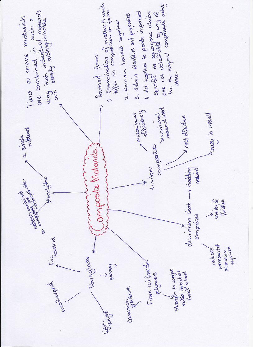
Lecture:This lecture helped to investigate property development and how such
developments are considered successful. The lecture covered 3 main locations as
examples of different property developments and the variation between them.
Theywere:. Royal Children's Hospital. l7l Collins street (BHP building)
' 35 Spring Street
The ideas and concepts explored by this lecture are shown in the mind map on
the following page.
eLearning
IIHODIC fTiID{mcre pror}e to corrosion}
Magnesium tZinc
Alumi*iumStnuctural Steels
Cast lrsnLeadTin
Copper, Brass, BrsnecNickel {fass*ve}
TitaniurnStainless st€eb a3O/3S413 Xfi
CATHODIC EHDttess prrn€ to csrroEionl
Figure: Table of electro valencies.( &.o\uo.." 5avres)

S,d?
z
/
(fiE56t./,̂d
\-g>ax
ryca
aa,UrfoE6t<)
a)3G
q{,x' '\ .,s.tg ''")B,2r^9<- )q''( ;s5\-? ,7
-'.
\prOzlr
/ %g/ <)@/EA/ ,,'€e
/ /d1
;,Pd53 -=-T+iiez.j 'b €;+{)
\\\
\ P4" ',r,5 / fl''.
sr--y €' ""a), &?r8
O/
3l-\d\o\ 3s 13cf, "9"*-rA
3€E 13 33
42;[.J{)}er\
+_4a,,,$26ld
{xA.'?1 ?},1r:;9Z 2t*I'))ts €-8€^ .; gi? qE'-,*-3 y :
a,"4-
".3 4'7urn
zaQ
-aiqqv/t
dl.5-
,,si9^6tCIc?( I
\€
treoa
9^ a)E__ Baq)
dl\Y\sr\>\;3€-hE
-fln6
'%r/9
€tt{
9ue
El€u_a
a.,)JsJdf<
'o),Qe'O:(-LG
€r tE\
E a \o,ra-d./r{:) t-- qt?' Ida9o:tj

Hest: r'5zstBP Es;Z4:'boc-,
€trqt 1*i"5
t -'an-.-.--*-i E .il >- 5 ->.9)
os' €'*ui.,;t
r3.-*j6
*
trB,r.,
-e? oi4\a,3.t6 7
e -!4---,
ta 'se'6)5*A
gB
ff4"-gU Y
g?
/.
\o
%I
-6olIz,F
5u,4e
ocri
s.\)O- oq
o\,E)\e€\J{}
a4\- sil,rc 2
Az,-,=-.9.3'ga
cr)"t
O/oCI
.J\0te)tf,cD"
Mood

!)s
4J*e?t#\ikn"'J -E 6
AA
;;
a)I
q',
wtGo.4
E.E
-<Q .,\TJ.)al_.t
:1': * 3.
E-"X', 9t>'' 1 I -'-E
h?3Q ;g !r i I53 a dfI =''q
It-$e?\r 4 X\\I /*tc
o9a- (rl\g+f
'g \-g,1"a9^gs
d?tI ia.,g
3,l 3u
x\6g
ht3s
s)ET':zo-6
€t---> 9
6€
\
,,)o.
tuC))JUa)
<-(a-)/a)
+-'r.J
Ir'.) ts8,..'l- i/-i1
bi
)tq9e"EZ
.tz
ry,?
;8Q/
t,t+r.-Pq 359 .6?8.t,ldt'ti.*vB
1 ,11^J 9iur
t3r\rrIB?
'gtu1o&{^ld
{lo9
,9j
\/ilz\air.
ils/\p)(6)
r,h
t.
Er
&o
ffi
2#,}-f, ?: \;Brff''-! {;€6517g t, n,,
1P\l Ir,!t L/"e 2Z* P"*1 #/+ 3s nl\T r,j)Z
-*/ SS ,--a--
,/* ?
'd)
??t
C.b
I.t'^'9,
{-)d14.',,g
d3i"r1
L4O/{o?o \st{)r$l:=J
+t:,*d?
:
Bsl
s
.r147-d5r;",;j?<' S)
apts
*.9F(B4?{rS h)
5/TP! ,.J34t.g, t=r-
f,{ *,r-*7 €€4€ r r,€ 3'
=r €?Et;:?# B,? { s
.attt'
leJo
\<,0?."2 , o<
2ri4 u'lc
i*31 -
":' t t.L,2. *
:E
$g'- -$ ="':''t'i;il;ortL sr i?-{-.1 :; .i 4
t 33 z ,s{,A ,rg.
a!'rA
\eo2d
k\k)
3\\s o
sg{lodure{dB
\t .t,2-.
//o
,ctn?
thT4

Glossary
Rafter- Sloping roof beams
Purlin- Run horizontal between rafters
FigUfe: the intefaCtiOnS Of faftefS and pUrlinS fhttp:l/wwwandvblackall.co.ukremphic desien4.html)
Cantilever- a horizontal member which is only secured at one end
portal Frame- consists of a series of braced rigid frames with purlins froof) and
girts (walls)
Eave- is the overhanging lower edge of a roof
Alloy- a mixture of a metal and another elementto improve or give differentproperties
Soffit- the underside of a particular element
Top chord- the upper horizontal structural member present with a truss

Week 7
Tutorials and LecturesBoth tutorial and lecture sessions did not run in week 7 due to the Easter break
eI parning
rrsrAs.rilG roR lttosnnE
Figure: Moisture deail witttin builder's drawings
cqwqgrd, nimseen
/lntemalsi*Airhnierm
+t,enlihtion
c &drahApI
Figure: Placement of capillary break to stop water from moving inside, high tolow pressure.
@I
ir^E c tiTt, tfi tt B t i +73q) g I s-#u'r
WTl s:t$u s,4Y-.tu=" B €;r E LIttit*{\ te 3$;\ q..' €3
*;l z e{\-E,-t.t I d-a 1 4 \t#\f€ +^7, \ ?:a Ae- ,{ao* -- .,"- '-E \tt'
I'--= &' ? e?E2
. 3 23-Z \Hx,h/ 5 332-g Th
-92
d*
o)f>
l;!-
3d/-gio/Qry79"<
Z*,
\
,t44,3
x4,(
qo'o\,24A
541^J<o6Z
fl,t9,"y3o
s)
4.6o,2
aSPtii B
', U'! 43'e.-r3 ;/ - a,E'I ? U
/ e o
r) Bs-r1 *iot
61,'e
vt-ra>6
E(rs,ts
tst3
rt q
qa€' 3i'rifl* $3? P\ ?g\vh'16'9r' E 'rv3E g
E '- 3'- ly)oY,
+9"*BoB'KP
6)q,
'6tior

ru L { s# u$.Y al*6 i.A\1 dE 1'*r j.?} I Aih; ? ii i 1,ii{leg-j{Hl 'lff? b',1
; { 3t ;?227iiq*i IT g'i
r \\; li L-e -3l'l't9': 4:I -u BiBt ,/ / \ Ar \I,'ffi { Y+
l#3.-l q1 I s
l:;,rr \, | \1 t e' Bl'6 -* q \L j_I %*e uq, \
I I 2:r3 re l%a-BI Y- <11
I te*111 , *g {. "\ g r)
I T7-zh 1,H+?Ei- t--_1 ?9
lil,"?tl I1Ht ;:* -t
9.'lg-o11o--?.
CJ
BsJC,
(t(r)
+ooo,*
",
d

GlossaryGutter- carry discharge tovertical down PiPes
Parapet- is an extension of a
particular wall to Protect thebuilding from uPward windforce. Also provides a sloPe for t
water to run off and awaY fromopenings.
Down pipe- take water fromgutters and discharge it into a
dry well or storm water system
Flashing- refers to the thincontinuous Pieces of sheet metalor other imPervious materialsinstalled to Prevent the Passageof water into the building
Insulation- the use of a material in an attempt to retain heaVreduce heat loss
heatwithin a building
Sealant- used to provide a protective seal against the passage of movement of
water and air
Drip- Used to stop the stream flow on member of the building causes the water
to drip
Vapour barrier- is a material of low perrneance installed in a construction to
p.J*r"r,a moisture from entering andreaching a pointwhere it can condense into
a liquid.

Week ITutorial:This tutorial was an opportunity to draw a re-scaled architectural drawing. We
started with a drawing of the oval pavilion with a scale of 1:5 and our object was
to transform it into a 1:1sketch, which included detailing.
o\u*:'*M\6'gcq sV'eakr'3
\ \i i i i.'
, aktfL
L *e&P^
Figure: Hand drawn 1:1 architectural plans from an orginial 1:5 drawing
,7
'.*'6#:$r.
il,,
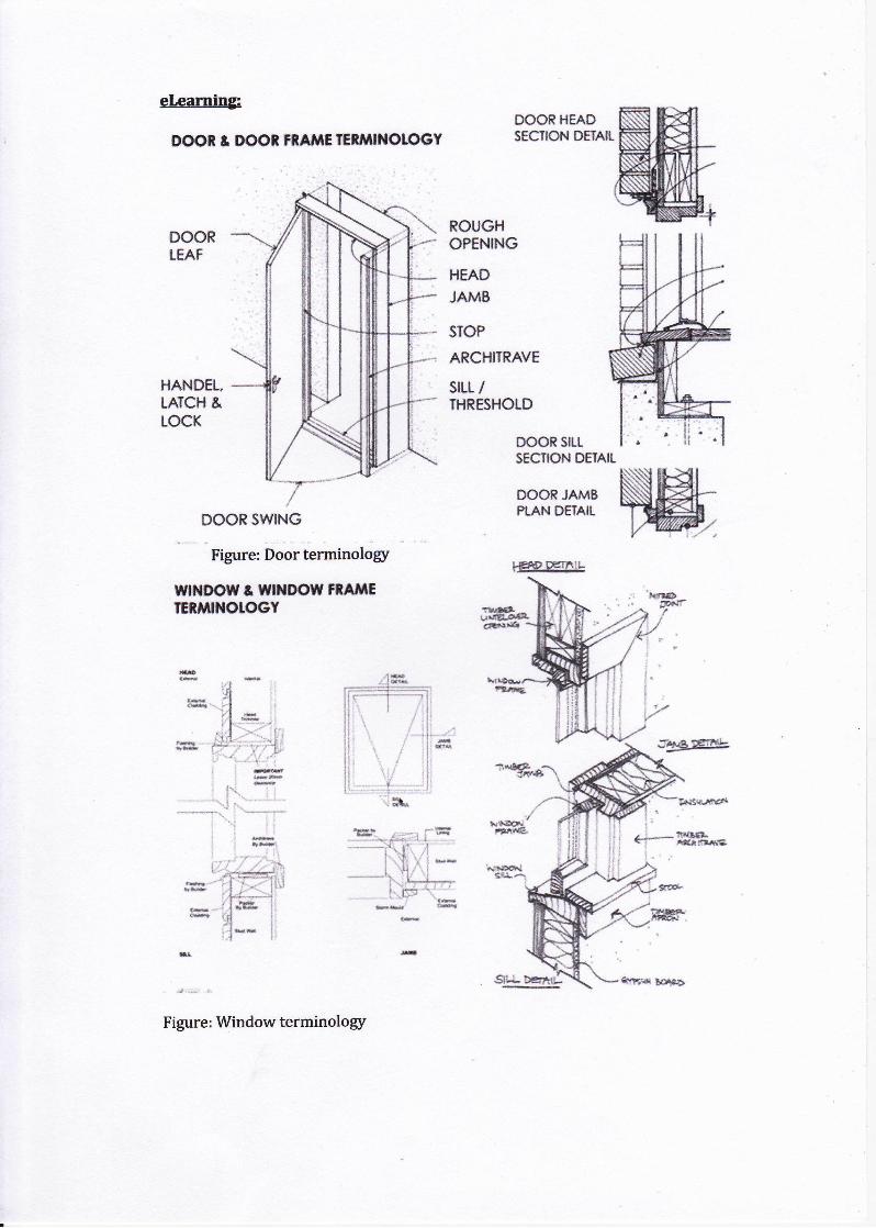
eleaming:
DOOi & DOOf, rnAilE rErrrill{olocY
HANDEL,TATCH &tocK
DOOR SWING
Figure: Door terminolory
WNDOTV t r$ltlDOMrfifiEEtl,ltNOIOGY
Figure: Window terminolory
DOOE HEADSECTION DETAIL
DOORLEAF
ROUGHOPENING
HEAD
JAMB
SIOP
ARCHITRAVE
SILL /IHRESHOLD
f\Sacr{irrt.'a
ru
I*AD DEr}ttIL

E1r-:E*o.? s ge3., Z s, Jd?'o ', P Bki1 i4 lad r"-r{ E -^ tt u
:1iE€'si?*1. i9+,1.e 3i93'Z t g
"*i1 's:YtrigfA-.-!"'J!'
$eBt
E
i e r+ni6\l/s,lt6d
<EEul4-6>--3's- 323Id
cf)=
-€z,a=oo
G/\
/\/
il€,r 4, E
B?t E
s)
"dA3e'rb| -ot
/ ,*,
' >%
-l^fig4v
A* \ E"EBrt / \ 'oz@A>6.2 / \
4o€.t
---*a(-)d
tc,.Y
doe,
R6(rf
3t -?gc>54olc [, oE: i\"1E{nn -sag-,-i5
\
6
+xo
'd"-ts,6
Efi-1 65-6
Q<5eo

GIossary:Window sash- refers to the fixed or movable framework of a window in whichpanes ofgtass are set
Deflection-is the perpendicular distance a spanning member deviates from a truecourse under tranwerse loading increasing with load and span, and decreasingwith an increase in the moment of inertia of the section or the modulus ofelasticity of the material
Moment of inertia-is the sum of the products of each element of an area and thesquare of its distance from the coplanar axis of rotation.
Stress-a combination of compression and tension stresses developed at a crosssection of a stmchrral member to resist a transverse force.
Shear Force-forces which actin both directions

Week 9TutorialThe construction site of the Portrait Building located on Swanston Street wasvisited in this week tutorial. As a class we examined the different aspects of thesites construction, including both structural and non-structural elements thatmake up the building. The construction was completed to floor 29, thus wherewe began our tour. It contains/will contain:
o 35 storieso 27 apartment levelso 536 apartments, which only 1- remains unsoldo Retail shopso Rooftop spas and BBQ
Completion of the structure is projected to be around Christmas this year.
These structural supports help stabilizethe formwork in which the slab to theabove level is poured.
These supports remain here until4subsequent levels are considered loadbearing. Then, the formworkwill beremoved from the bottom most leveland added to the next level being built.
The edge of the building was caged onevery level which hadn'tyet had theoutglass windows installed. The cage ispositioned slightly further out from thebuilding. This allows workers to workon parts of the buildingwhich overhang,allowing for certain processes whichwould otherwise notbe availablewithout these caged fences.
The concrete slabs are compositematerials. They are poured and curedwith mesh and cables. This makes itareinforced post-tension concrete slab.
The cables are pulled extremely tightunder high tension, to straighten theslab. They metal casing is then filledwith grout, into the yellow tubeshighlighted, to retain tension and stopthe slab sinking. This is done on the
outer edge using the cages for safety from falling.

Two cranes were used on site to liftheavy materials to either the top floor orto loading docks located on lower levels,which the materials are then slid intothe building.
Loading materials into the building is aprocess that must be well thoughtthrough, otherwise, larger materialssuch as plasterboards, may not be ableto fit into certain rooms if structure isalready built
Concrete is transported through thecentre of the building, the core, usingthe machinery seen in this photo.
The core of the building is establishedfirst, as it provides a centre point forconstruction.
The blue piping is the concretetransportation. It runs through a shaftfrom the bottom floor to the top, muchsimilar to an elevator shaft but on asmaller scale.
This technology has increased the speedof construction greatly. The tour guideemphasized the speed of slab pouring,indicating that 1 floor worth of concretecan be poured every 4 days. This is 1400square meter area.
Allow slabs are poured on site, the useof precast concrete is still heavilyobservable. It is mainly used in columnand shear walls
The red plastic moulds prevent concretefrom filling certain areas. This forms a
rylindrical casted area for pipes so thatthey can easily be fitted through theslab.

Sbrour lonrlns
tgf,tdtrldh ponelt
COflt0$lt t lolor'glil coftl€ trl fllt*tny l*trftl t)ul tiiey cort Dtrt glcx;;}arl in l0 lf}lt n';dlrl'r lyrlel
s.S. Fro.ducl! e.9. tgf,tctttldn ponelt e'lcGrlt$lllfit{}rr{' (}st lrftti**'. C,
{:sflt!ni.+i,l f,tJaat
Figure: different types of composite materials
com$oo?r+n5 cl two0d fti:.{': fcn}fJ$}if$!ytfr:1
GlossarvSandwich panel- two aluminium sheets which contain a non-aluminium core
material
Bending- additional loading causes the column to deflect further until collapseoccurs in the means of bending
Skirting- predominatelywooden board running along the bottom to protect theplaster from damage
Composite Beam- a beam formed from two or more dissimilar materials whichjoined together to act as a single unit
Shadow line joint-a joint ffiically used for stone, and is joined closer to thecentre of the objec! with a slight gap seen easily in the connection, as shovrm
--...'.
Cornice- a moulded projection that crowns a wall or divides it horizontally forcompositional purposes
po$cukcla
e.q. eEovet or}d tel,nr
hybttd
1t 1 rtl:,l31 liaHL
z\?,\,1 1pgi:L i3ft1 ia(-'+ d Ml '<<r
B,io,4,u.t6S5qd):6:3'
JDd>cJ
B4,:1d*)<rtr3n,2:<a'
1"2,r,
,*aE5TJ
:d€o
Jsjur'!t)
s
,9:
r1.,e93€oc,,
ozg
2,, a2,
3-€tsl
oE
€
!1-
-Q
,J"2 1o
d
c)
6
-dJ-e,S;
ra&Bg,7 -)'/7
u4E
\
.=,E4Efr
qeL
tstrat, er
i
.n-6ts%
o)p-'oo
€*t ?i-1,
W;'"-i,#3
6o-{.*6_
->z &'2
I-l<6)
+
:B!(f,2
-6
Az€o
-ti lt€ E": rBt
$d o.^)J^ s -
y-'},,
\ ,'9*J,}
\-a\
111?
oa5n,,#r;
e"K
tut?$

to'g .r8,2o6
a
;\
a\)\-. -s 8sS<1.R>US qrj(5
_3c.)
ol
Rud
d-I
dt
1
41**{34g,ijg
\:€3; {' }* q"q
5H
ldr 4t\)a
0t_?t
aJd3fsg \f*
t ?I9. ,&l'\3\9,cy
d).t'q)6)
1€*e
""+,€tr
----..-t 99),(n
G'4
\go€z
Z*
?s,t6,
tL5
\
3'\ 3j<))
o63.3
?
Bq)
e/6, c)c,r'da9raL
I,9h
\{
U+{()o'fE"-.1et
,zo,d
oE€2
"6eo
,-)

Week 10
TutorialThis tutorial was used to join our scale drawings together and make apresentation to the class regarding what we have drawn and the structuralmember and interactions that make up the specific section of the building.
eLearninp
*+t 4.6**# t** r*S*#*l| - ;,;'e.j-;.1$: r' $i. & t :t::q
fi.&. { i. 48 t5*L€:1*f r,.*&ib.r,:.rt' f ,,idh .t{i,ir&q
I r,:.*l,SrSilS' l:, t* ilt
*rq ::,$t $.* 6{n i,.A 9So,l,t, {'.8
-'r$rr{ r ..
cq"trt *dt
Figure: Representation of corrosion occurring in the Statue of liberty. Waterpenetration causing expansion
Villains for health - glue, timber floor finishes, paintsHeroes for health- bamboo flooring, termimesh - alternative to chemicaltreatment against termites
Villains for waste- Timbers, tilingHeroes for waste- sisalation, rerycled timber, recycled fabrics, roof tiles
Villains for energy- aluminium (liquid energ5r),light globes, downlightsHeroes for energy- timber, Australian made,less transport, Diode lights
Villains for pollution- PVC, cigarette smokeHeroes for pollution- linoleum flooring, tiles, non PVC cables, wool
q*r.r *f , t*1,."

nU1,-ancJO
-\) O:{
,4q) 2g *,3*
Pa A', fiqD)
\+p
E*t1 f,$q dt lo
fsY9,
sJ\ng
Bii4 zj"t -s*B, \,+3 }"rt1i?
't9.,)6{qs
6S
; Lrt)o 3 19,U r q/2! -'Z
g;t--t qf) ,//
'9u &
€so5
'yf.tdfr
I/\)
E'zZ.+< *96on
"F-)--3
aQ-
E
"\
dd
-3*
1*FoE-x" ld)/
o)
q---(.)
Erc)
tg
"1
;
ra-9\A
/_.g6
,'fir.'ig1,i.I1Zi
't(rt<,14,:61\ ,z; .6)'d3
,\a\s\ .v!
5
-'g."4
1\
96>*
*o
I.fi
#3s 'BlI a16) cy'dotdagv9
ffi1,/q,
bo%'
%\4d al{6i
34, 1
d,r*4dt6,
g),6sa
UJ
s9b
t4/a
{'a
\LoEJ
\
'i zig,\
a:?
4d
SEsd3s o-9-
EElt\o
55
cl)C'oQ- >|
-6-t?
2
/
!-6
9.t_
9
?J_
*)o')
t2
9*ql
aJgi./- d3z
-4\)
),go,
3sotr)
1#,+*
"B
'8n od),'{y'-,I6
Ya)B&
a)
1nj
g{&ec
rd I
$ )a "*3' Lt an'&3
3 Sdi
tv/3 ,,"6z _€
e
3 \)B.rU6lc
4-g(5f
3 9o1
Pe\,
*4o93+
.(oo)2,6
C}
e6

GlossarySheer wall- a structured wall made up of braced panels
Soft story- exists in a building when one or more floors are significantly weaker
o. .or" h"*ible than those above and/or below. They result in uneven load
distribution and are often cause by architectural desires in bottom floor lobbies
etc.
Braced frame- bracing added to a new or existing frame structure to help against
wind and earthquake forces
Lifecycle- the creation, use and waste management of a particular material over
time (it's "life")
Deflect- a deflection of a structural element measure in degrees
Fascia- situated underneath a roofs edge and runs horizontally
Corrosion- the destruction of materials over time due exposure to weather
conditions causing chemical reactions
IEQ- Indoor environment quality, refers to health when using materials

References:
Francis D.K Ching, 2008, building construction illustrated (4t'ed.), Hoboken, New
fersey: fohn Wiley & Sons
The university of Melboume, 2OL4, Flipped Classroom, Retrieved from
https://app.lms.unimelb.edu.au/webapps/portal/frameset.isp?tab tab group id= 5 1&
url=%2Fwebapps%2Fblackboard%2Fexequte%o2Flauncher%.3Ftypeo/o3DCourse%26ido/o3D 27 L852 Lo/o26urlo/o3D