Embed Size (px)
Citation preview

Ι w
ww
.3ds.c
om
Ι ©
Dassault S
ystè
mes Ι
Confidential In
form
ation Ι
04/1
1/2
011
ref.:
20100928M
KT
038 Ι
Matthew Hopkins, Ann-Marie Lambert
Tortworth Court, South Gloucestershire
SIMULIA Tutorial

Ι w
ww
.3ds.c
om
Ι ©
Dassault S
ystè
mes Ι
Confidential In
form
ation Ι
04/1
1/2
011
Ι
SIMULIA Tutorial
Agenda
• ATOM – Abaqus Topology Optimisation Module
• Introduction and demonstration
• Latest Enhancements in Abaqus/CAE
• A summary of enhancements and demonstration

Ι w
ww
.3ds.c
om
Ι ©
Dassault S
ystè
mes Ι
Confidential In
form
ation Ι
04/1
1/2
011
ref.:
20100928M
KT
038 Ι
Abaqus Topology Optimisation Module (ATOM)

Ι w
ww
.3ds.c
om
Ι ©
Dassault S
ystè
mes Ι
Confidential In
form
ation Ι
04/1
1/2
011
Ι
SIMULIA Tutorial
ATOM
• What is ATOM?
• ATOM stands for Abaqus Topology Optimization Module
• It allows for convenient setup and postprocessing of two classes of
Structural optimization problems
1. Topology optimization
2. Shape Optimization

Ι w
ww
.3ds.c
om
Ι ©
Dassault S
ystè
mes Ι
Confidential In
form
ation Ι
04/1
1/2
011
Ι
SIMULIA Tutorial
Topology Optimization
• Given an initial material distribution (left), topology optimization produces
a new landscape (right) by scaling the relative densities of the elements
in the design domain.
• Elements with large relative densities are retained whilst those
elements whose relative densities have become sufficiently small
are assumed to be voids. Thus a new “landscape” is obtained.

Ι w
ww
.3ds.c
om
Ι ©
Dassault S
ystè
mes Ι
Confidential In
form
ation Ι
04/1
1/2
011
Ι
SIMULIA Tutorial
Shape Optimization
• Shape optimization refers to procedures that result in the prediction of a
boundary (or shape) of the design domain of the structural/mechanical system
to be optimized.
• In a finite element analysis, nodes on the boundary are displaced in order
to achieve an objective (minimise the stress on the surface for example).
• Thus, a new shape is obtained.
Ι w
ww
.3ds.c
om
Ι ©
Dassault S
ystè
mes Ι
Confidential In
form
ation Ι
04/1
1/2
011
Ι
SIMULIA Tutorial
ATOM
• Both Topology and Shape Optimisation support:
• Contact
• Geometric non-linearity
• Nonlinear Materials:
• Within the design area: *plastic, *hypoelastic, most *hyperelastic
• Outside design area: all
• Manufacturing restrictions
• Export smoothed shape to STL or INP

Ι w
ww
.3ds.c
om
Ι ©
Dassault S
ystè
mes Ι
Confidential In
form
ation Ι
04/1
1/2
011
Ι
SIMULIA Tutorial
ATOM Workflow: Setup
• The flow chart on the left shows the user
actions required to setup the optimization
• Each user action is associated with a
manager in the Optimization module
accessible from the Optimization
Module Toolbox or the Model Tree
Ι w
ww
.3ds.c
om
Ι ©
Dassault S
ystè
mes Ι
Confidential In
form
ation Ι
04/1
1/2
011
Ι
SIMULIA Tutorial
ATOM: Basic Terminology
• Design Responses provide variables for the optimization
solver
• For example: Strain Energy, Displacement etc.
• Objective Functions define how those
Design Responses should be used
(sum/min/max/formula/etc)
• Minimise Strain Energy (maximise stiffness)
• Constraints determine bounds for the optimization solver
• For example: Constraint the volume to be less than
35% of the original volume
• Geometric Restrictions provide for manufacturing
restrictions
• For example: de-molding direction with draft angle
• Stop conditions
• Maximum number of iterations

Ι w
ww
.3ds.c
om
Ι ©
Dassault S
ystè
mes Ι
Confidential In
form
ation Ι
04/1
1/2
011
Ι
SIMULIA Tutorial
ATOM Workflow: Execution and Monitoring
• Once an Optimization Task is setup, an Optimization Process needs to be defined to execute the optimization
• Users may have multiple Abaqus models and optimization tasks defined. An optimization process refers to a unique Model and Task combination.
• Right-click on the optimization process to access: Validate, Submit, Restart, Monitor, Extract and Results postprocessing

Ι w
ww
.3ds.c
om
Ι ©
Dassault S
ystè
mes Ι
Confidential In
form
ation Ι
04/1
1/2
011
Ι
SIMULIA Tutorial
ATOM Workflow: Results
• The Abaqus Visualization module allows for convenient visualization of optimization results
• Postprocessing will be shown in more detail during the demonstration

Ι w
ww
.3ds.c
om
Ι ©
Dassault S
ystè
mes Ι
Confidential In
form
ation Ι
04/1
1/2
011
Ι
SIMULIA Tutorial
ATOM Workflow: Extraction
• Optimization
results can be
smoothed and then
extracted as
Abaqus input files
or STL files

Ι w
ww
.3ds.c
om
Ι ©
Dassault S
ystè
mes Ι
Confidential In
form
ation Ι
04/1
1/2
011
Ι
SIMULIA Tutorial
SIMULIA’s Design Exploration and Optimization Tools
ATOM Isight
Tuned for topology and shape
optimization
A general purpose design exploration
and optimization package
Non parametric Parametric
Can handle a very large number of
design variables. (~100K-1000K)
Meant for small number of design
variables(~10-100)
Multiple objectives are summed up to
single objective
Multi-objective, multi-discipline
optimizations possible
ATOM Isight
DOE
Monte Carlo
Exporation
Taguchi RD
Six Sigma
Optimization
Topology
optimization
Shape
optimization
Test Data
Match

Ι w
ww
.3ds.c
om
Ι ©
Dassault S
ystè
mes Ι
Confidential In
form
ation Ι
04/1
1/2
011
ref.:
20100928M
KT
038 Ι
Optimisation of a Brake Pedal
Demonstration

Ι w
ww
.3ds.c
om
Ι ©
Dassault S
ystè
mes Ι
Confidential In
form
ation Ι
04/1
1/2
011
Ι
SIMULIA Tutorial
ATOM Brake Pedal Demonstration
• Linear elastic Steel material
• Nonlinear Geometry
• Loading causes out of plane warping effects
Ι w
ww
.3ds.c
om
Ι ©
Dassault S
ystè
mes Ι
Confidential In
form
ation Ι
04/1
1/2
011
Ι
SIMULIA Tutorial
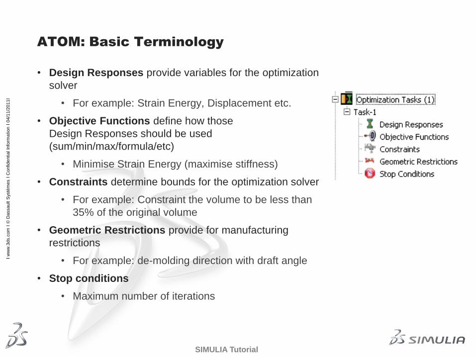
ATOM Brake Pedal Demo
• Objectives
• To maximise the stiffness (minimise Strain Energy)
• Constraints
• Final volume <=40% of original volume
• Lateral Displacement <=2mm

Ι w
ww
.3ds.c
om
Ι ©
Dassault S
ystè
mes Ι
Confidential In
form
ation Ι
04/1
1/2
011
ref.:
20100928M
KT
038 Ι
Leveraging the Latest Enhancements
in Abaqus/CAE

Ι w
ww
.3ds.c
om
Ι ©
Dassault S
ystè
mes Ι
Confidential In
form
ation Ι
04/1
1/2
011
Ι
SIMULIA Tutorial
Summary
• CAD Interfaces
• Demonstration: CATIA V5 bidirectional
• Midsurfacing and meshing
• Demonstration
• Results visualisation
• Demonstration: Contour of beam stresses

Ι w
ww
.3ds.c
om
Ι ©
Dassault S
ystè
mes Ι
Confidential In
form
ation Ι
04/1
1/2
011
Ι
SIMULIA Tutorial
CATIA V5 Bidirectional Associative Interface
Abaqus 6.10-EF
One directional associatively for
• CATIA V5
• SolidWorks
• Pro/ENGINEER (Wildfire)
• UG NX
Bidirectional associatively for
• Pro/ENGINEER (Wildfire)
New in 6.11
• Bidirectional associative interface for
CATIA V5
• Both R19 & R20 version
• CATIA parameters can be modified from
within Abaqus/CAE
• Model is updated in Abaqus/CAE.
CAD geometry and parameters
exported to Abaqus/CAE
Updated parameters
export to CATIA V5

Ι w
ww
.3ds.c
om
Ι ©
Dassault S
ystè
mes Ι
Confidential In
form
ation Ι
04/1
1/2
011
Ι
SIMULIA Tutorial
CATIA V5 Bidirectional Associative Interface
Create/Define Parameters in CATIA V5
• Parameters defined in CATIA with “ABQ_” prefix are exported
• Parameters should be defined at part level
• Only Real, Integer, Length and Angle type parameters with single value are
supported.
• User parameters will appear in the specification tree under “Parameters”

Ι w
ww
.3ds.c
om
Ι ©
Dassault S
ystè
mes Ι
Confidential In
form
ation Ι
04/1
1/2
011
Ι
SIMULIA Tutorial
CATIA V5 Bidirectional Associative Interface
Exporting the Geometry and Parameters from CATIA
1) Ensure that CATIA V5 connection is enabled
2) In CATIA, use Abaqus plug-in or Abaqus/CAE icon to export the model.
3) CATIA writes a parameter file(.par_abq) and exchange (.eaf) file.
4) Parameter file is xml based
• Contains parts and parameters information
Quick Export Menu which allows user to set/change the
export option and export the model

Ι w
ww
.3ds.c
om
Ι ©
Dassault S
ystè
mes Ι
Confidential In
form
ation Ι
04/1
1/2
011
Ι
SIMULIA Tutorial
CATIA V5 Bidirectional Associative Interface
Viewing/Modifying parameters
• Parameters can be viewed in
Part/Assembly module.
• In the Part module, /CAE will
display parameters of active
part only.
• In the assembly level, /CAE
will display parameters of all
the parts in the assembly.
• In Part module use,
ToolsCAD Parameters…
• In the Part module use
ToolsCAD InterfacesCAD
Parameters…

Ι w
ww
.3ds.c
om
Ι ©
Dassault S
ystè
mes Ι
Confidential In
form
ation Ι
04/1
1/2
011
Ι
SIMULIA Tutorial
CATIA V5 Bidirectional Associative Interface
Viewing/Modifying parameters
• Selecting a row in CAD
Parameters dialog will highlight
the geometric faces associated
the selected parameter.
• To modify the values from
/CAE, change one or more
parameters values and click
update.
• “Update” will propagate the
changes to the CATIA model
and re-export the model to
/CAE.
• /CAE will regenerate the
assembly/part.
Ι w
ww
.3ds.c
om
Ι ©
Dassault S
ystè
mes Ι
Confidential In
form
ation Ι
04/1
1/2
011
ref.:
20100928M
KT
038 Ι
CATIA V5 Bidirectional Interface
Demonstration

Ι w
ww
.3ds.c
om
Ι ©
Dassault S
ystè
mes Ι
Confidential In
form
ation Ι
04/1
1/2
011
ref.:
20100928M
KT
038 Ι
Midsurfacing and Meshing

Ι w
ww
.3ds.c
om
Ι ©
Dassault S
ystè
mes Ι
Confidential In
form
ation Ι
04/1
1/2
011
Ι
SIMULIA Tutorial
Mid-surfacing
• Manually create mid-surface representation
of thin solids using geometry edit tools:
• Face offset
• Face extend/blend
• Auto-trim
• Benefits beyond mid-surfacing
• Mechanism for capturing thickness of
parent solid geometry and association with
shell mesh.
• Thickness query and display tools

Ι w
ww
.3ds.c
om
Ι ©
Dassault S
ystè
mes Ι
Confidential In
form
ation Ι
04/1
1/2
011
Ι
SIMULIA Tutorial
Mid-surfacing
• Examples: Wheel hub (shown with view cut)

Ι w
ww
.3ds.c
om
Ι ©
Dassault S
ystè
mes Ι
Confidential In
form
ation Ι
04/1
1/2
011
Ι
SIMULIA Tutorial
Mid-surfacing enhancements
• Reduce picking needed to create mid-surface
• Improved robustness
• Offset operation performance
• Feature regeneration
• New tool for partitioning faces by edge projection
• Enhanced heuristics for Extend and Blend geometry tools

Ι w
ww
.3ds.c
om
Ι ©
Dassault S
ystè
mes Ι
Confidential In
form
ation Ι
04/1
1/2
011
Ι
SIMULIA Tutorial
Midsurfacing Enhancements
Auto-selection of Target Faces
• Selection of target faces can be time-consuming
• Option to automatically select target faces based on proximity
• Manual modification of selection
• Available only if faces being offset belong to reference representation
Target faces auto-selected
Source face to be offset

Ι w
ww
.3ds.c
om
Ι ©
Dassault S
ystè
mes Ι
Confidential In
form
ation Ι
04/1
1/2
011
Ι
SIMULIA Tutorial
Midsurfacing Enhancements
Option to Extend Target Faces Before Trimming
• Using target faces to limit extension is a useful way to fill gaps between
neighboring shell faces
• Target faces may sometimes need to be extended (internally) for the
purposes of trimming the selected faces
• Allows user to decide whether to extend target faces
• OFF by default. Turn ON only when needed
Target face needs to be
extended for trimming
Extend
target
face
Target face need not
be extended
Selected face
being extended
Target face
gap

Ι w
ww
.3ds.c
om
Ι ©
Dassault S
ystè
mes Ι
Confidential In
form
ation Ι
04/1
1/2
011
Ι
SIMULIA Tutorial
Midsurfacing Enhancements
Thickness Attributes on Faces Created by Blend/Cover
• Faces created by Blend or Cover will have thickness automatically assigned to
them if the neighboring faces have thickness attributes
2 Offset Faces Thickness data on
the Offset Faces
New blend face with
thickness inherited
from neighbors
GUI to verify
assigned thickness

Ι w
ww
.3ds.c
om
Ι ©
Dassault S
ystè
mes Ι
Confidential In
form
ation Ι
04/1
1/2
011
Ι
SIMULIA Tutorial
Mesh Editing
• New mesh edit functions
• Merge/subdivide elements
• Grow/collapse short element edges
• Bottom-up meshing
• Now available for orphan meshes
• Generate elements by offsetting
• Additional options for extrude method

Ι w
ww
.3ds.c
om
Ι ©
Dassault S
ystè
mes Ι
Confidential In
form
ation Ι
04/1
1/2
011
ref.:
20100928M
KT
038 Ι
Midsurfacing and Meshing
Demonstration

Ι w
ww
.3ds.c
om
Ι ©
Dassault S
ystè
mes Ι
Confidential In
form
ation Ι
04/1
1/2
011
ref.:
20100928M
KT
038 Ι
Results Visualisation
Ι w
ww
.3ds.c
om
Ι ©
Dassault S
ystè
mes Ι
Confidential In
form
ation Ι
04/1
1/2
011
Ι
SIMULIA Tutorial
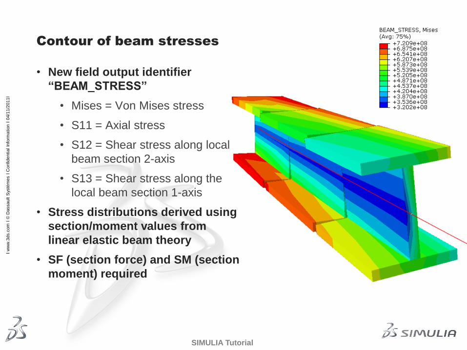
Contour of beam stresses
• New field output identifier
“BEAM_STRESS”
• Mises = Von Mises stress
• S11 = Axial stress
• S12 = Shear stress along local
beam section 2-axis
• S13 = Shear stress along the
local beam section 1-axis
• Stress distributions derived using
section/moment values from
linear elastic beam theory
• SF (section force) and SM (section
moment) required

Ι w
ww
.3ds.c
om
Ι ©
Dassault S
ystè
mes Ι
Confidential In
form
ation Ι
04/1
1/2
011
ref.:
20100928M
KT
038 Ι
Beam Contouring Demonstration

Ι w
ww
.3ds.c
om
Ι ©
Dassault S
ystè
mes Ι
Confidential In
form
ation Ι
04/1
1/2
011
ref.:
20100928M
KT
038 Ι
Presented at the
2011 SIMULIA UK RUM
Leveraging the Latest Enhancements
in Abaqus/CAE