Embed Size (px)
Citation preview
EXIT PWR
ALARM
POWER /SOLAR IN
BATTERYINPUT
OPENING CLOSING
CLOSINGOPENING
ERD
OBD PORTBLACK BOX
PROGRAMMING
SOLAR MODE
PROGRAM
MOTOROVERLOAD
ERD
MOTOROVERLOAD MAX
OFF
MAXSENSE
MAXSENSE
BATTERYBACKUP MODE
ERD SENSITIVITY
MOTION CONTROL
OPEN
GATE SPEED
MAGLOCK
ULENTRAP
PRIMARY/SECONDARY
LINK
STOP CLOSE
MOTORINPUTS
CLOSETIMER
MAGLOCKDELAY
JOG
BATTERYTEST
INPUTERROR
BATTERY
BATTERYIN USE
REPLACEBATTERY LEAVE
CLOSED
LEAVEOPEN
OPEN1 TIME
BATTERY VOLTAGEE F1/2
RESET /MANUALRELEASE
IDPLUG
LINKOK
MODULEPORT
MOTORPOSITIONINPUTS
SLIDERLIMIT
SWINGLIMIT
GND
OPEN ONLY NC
OPEN ONLY 10K
PHOTO CLS NCOPEN/CLS NC
GND12VDC OUT
GND
GND
GND
GND
GND
GND
JOG
RIGH
TJO
G LE
FT
TAMP
ER IN
TAMP
ER N
O
GATE
DISA
BLE
MANU
AL RE
LEAS
E
KEYP
AD / C
ARD
GND
(-)(+)
GND
GND
MAX
OPEN
FIRE
DEP
T
RADI
O GN
DRA
DIO
SIGNA
L
STRI
KE
CLOS
ECO
M
COM
STOP
OPEN
PHOTO CLS 10KOPEN/CLS 10K
12VDC OUT
NOCOM
NC
ID PLUGERROR
24VDC OUTPUT
12VDC OUTPUT
GND
GND
GND
LOOP PWROFF
PRIMARY
LEFT
ON/OFFBATTERY
RIGHT
SECONDARY
ON
QUICKCLOSE
OPENLEFT
OPEN RIGHT
GATEOFF
123456789
10
123456
MIN MIN
MAX MAX
ON
OFF 2.5 sec1.5 sec
FAULTSOPERATOR
MATRIX III
OFF
OFF
3
1
1416
MIN16
MIN12
9
73
1
14 12
9
7
UL S
ENSO
R N.
C.UL
SEN
SOR
10K
POWER
MODE
AMO
DE B
EXIT LOOP
LOOP
LOOP
CENTER
SAFETY
GATE OPENCOM
GATE CLOSED
MIN
MATRIX IIISWING / SLIDE
www.max.us.com
Matrix III General Swing / Slide SETTINGS Overview
© 2018 Maximum Controls LLC. All rights reserved.
Maximum Controls LLC.10530 Lawson River Ave
Fountain Valley, Ca 92708Tel: (949) 699-0220
FUSE7 Amp
POWER
115VAC 3A maxOn
Off
WARNING: For continued protection
against fire, re
place only with the
same type and rating of fuse.
AVERTISSEMENT: pour ne pas
compromettre la protection contre les
risques d’incendie, utiliser un fusible
de mêmes type et caractéristiques
nominales.
MAX Swing
Toroid Box
disconnect
power before
servicing unit
WARNING
HIGH
VOLTAGE!
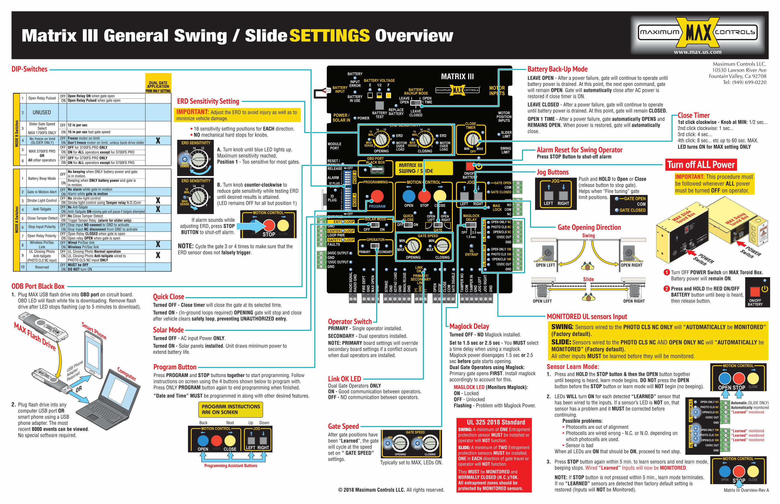
Battery Back-Up ModeLEAVE OPEN - After a power failure, gate will continue to operate until battery power is drained. At this point, the next open command, gate will remain OPEN. Gate will automatically close after AC power is restored if close timer is ON.
LEAVE CLOSED - After a power failure, gate will continue to operate until battery power is drained. At this point, gate will remain CLOSED.
OPEN 1 TIME - After a power failure, gate automatically OPENS and REMAINS OPEN. When power is restored, gate will automatically close.
Maglock DelayTurned OFF - NO Maglock installed.
Set to 1.5 sec or 2.5 sec - You MUST select a time delay when using a maglock. Maglock power disengages 1.5 sec or 2.5 sec before gate starts opening.Dual Gate Operators using Maglock: Primary gate opens FIRST. Install maglock accordingly to account for this. MAGLOCK LED (Monitors Maglock): ON - Locked OFF - Unlocked Flashing - Problem with Maglock Power.
Operator SwitchPRIMARY - Single operator installed.SECONDARY - Dual operators installed.NOTE: PRIMARY board settings will override secondary board settings if a conflict occurs when dual operators are installed.
Link OK LEDDual Gate Operators ONLYON - Good communication between operators.OFF - NO communication between operators.
Close Timer1st click clockwise - Knob at MIN: 1/2 sec... 2nd click clockwise: 1 sec... 3rd click: 4 sec...4th click: 8 sec... etc up to 60 sec. MAX.LED turns ON for MAX setting ONLY
Quick CloseTurned OFF - Close timer will close the gate at its selected time.Turned ON - (In-ground loops required) OPENING gate will stop and close after vehicle clears safety loop, preventing UNAUTHORIZED entry.
Solar ModeTurned OFF - AC input Power ONLY.Turned ON - Solar panels installed. Unit draws minimum power to extend battery life.
DIP-Switches
Gate SpeedAfter gate positions have been “Learned”, the gate will cycle at the speed set on “ GATE SPEED” settings.
Typically set to MAX, LEDs ON.
CLOSINGOPENING
GATE SPEEDMI MN INMINMINMINMIMM MINMINMINMIMM
MAX MAX
MOTION CONTROL
OPEN STOP CLOSE
JOG
LEFT RIGHT
Programming Assistant Buttons
NextBack Up Down
Program ButtonPress PROGRAM and STOP buttons together to start programming. Follow instructions on screen using the 4 buttons shown below to program with.Press ONLY PROGRAM button again to end programming when finished.
“Date and Time” MUST be programmed in along with other desired features.
PROGRAM INSTRUCTIONSARE ON SCREEN
ERD SENSITIVITY
MIN16
3
1
14 12
9
7
MAXSENSE
ERD SENSITIVITY
MIN16
3
1
14 12
9
7
A. Turn knob until blue LED lights up.Maximum sensitivity reached,Position 1 - Too sensitive for most gates.
B. Turn knob counter-clockwise to reduce gate sensitivity while testing ERD until desired results is attained.(LED remains OFF for all but position 1)
NOTE: Cycle the gate 3 or 4 times to make sure that the ERD sensor does not falsely trigger.
• 16 sensitivity setting positions for EACH direction.• NO mechanical hard stops for knobs.
16N
16N
16IN
1MINMINMINMINMIN
1
If alarm sounds while adjusting ERD, press STOP BUTTON to shut-off alarm.
IMPORTANT: Adjust the ERD to avoid injury as well as to minimize vehicle damage.
MOTION CONTROL
OPEN STOP CLOSE
ERD Sensitivity Setting
MAXSENSE
2. LEDs WILL turn ON for each detected “LEARNED” sensor that has been wired to the inputs. If a sensor’s LED is NOT on, that sensor has a problem and it MUST be corrected before continuing. Possible problems: • Photocells are out of alignment • Photocells are wired wrong - N.C. or N.O. depending on which photocells are used. • Sensor is bad When all LEDs are ON that should be ON, proceed to next step.
3. Press STOP button again within 5 min. to learn sensors and end learn mode, beeping stops. Wired “Learned” Inputs will now be MONITORED.
NOTE: If STOP button is not pressed within 5 min., learn mode terminates. If no “LEARNED” sensors are detected then factory default setting is restored (Inputs will NOT be Monitored).
MOTION CONTROL
OPEN STOP CLOSE
MOTION CONTROL
OPEN STOP CLOSE
OPEN ONLY NC
OPEN ONLY 10K
PHOTO CLS NC
OPEN/CLS NC
GND
12VDC OUT
GND
PHOTO CLS 10K
OPEN/CLS 10K
12VDC OUT
UL S
ENSO
R N.
C.UL
SEN
SOR
10K
SENS
ORSE
NSO
SENS
OSE
NSO
SENS
OEN
SOEN
SEN
SNS
MONITORED UL sensors Input
“Learned” monitored
“Learned” monitored“Learned” monitored“Learned” monitored
Automatically monitoredAutomatic (SLIDE ONLY)
Turn off ALL PowerIMPORTANT: This procedure must be followed whenever ALL power must be turned OFF on operator.
ON/OFFBATTERY
Gate Opening Direction
SWING: A minimum of ONE Entrapment protection sensor MUST be installed or operator will NOT function.SLIDE: A minimum of TWO Entrapment protection sensors MUST be installed, ONE in EACH direction of gate travel or operator will NOT function.
They MUST be MONITORED and NORMALLY CLOSED (N.C.)/10K.All entrapment zones should be protected by MONITORED sensors.
UL 325 2018 Standard
JOG
LEFT RIGHT
Push and HOLD to Open or Close (release button to stop gate). Helps when “Fine tuning” gate limit positions.
Jog Buttons
Alarm Reset for Swing OperatorPress STOP Button to shut-off alarm
Sensor Learn Mode:
GATE OPENCOM
GATE CLOSED
OPEN LEFT OPEN RIGHT
Swing
Slide
OPEN RIGHTOPEN LEFT
AC
IN FUSE
7 AmpPOWER
On
Off
www.Max.US.com
MAX Toroid 15 Amp
Select Input
Voltage
115VAC or
230VAC115V
MAX Slide
Toroid Box
1 Turn OFF POWER Switch on MAX Toroid Box. Battery power will remain ON.
2 Press and HOLD the RED ON/OFF BATTERY button until beep is heard, then release button.
POWERSwitchPOWER
Switch
1. Press and HOLD the STOP button & then the OPEN button together until beeping is heard, learn mode begins. DO NOT press the OPEN button before the STOP button or learn mode will NOT begin (no beeping).
SWING: Sensors wired to the PHOTO CLS NC ONLY will “AUTOMATICALLY be MONITORED” (Factory default).SLIDE: Sensors wired to the PHOTO CLS NC AND OPEN ONLY NC will “AUTOMATICALLY be MONITORED” (Factory default).All other inputs MUST be learned before they will be monitored.
O10K
O10K
O10K
O10K
O10K0K0K0K0K
HSOR
OO11 O1 O1 O1000SO
R
H
R
OO11 O11100OR PH
RR
OO11111OR P
RRR1111
OR P
RRRR1
OR P
RRRRROR P
RRRRR R OORRRRROORR
O
L SE
NS
HS PSSO PO PO PO PO PO POO
OSENSS
PS PSSO PO PO PO PO POSE
NSSS
PS PSSO PO PO POOSE
NNSSS
PS PSSO PO POSE
NNNSSS
PS PSSOOSE
NNNSSSSSSENNNNS SSS
ENNNNNS S
ENNNN
obd
port
ODB Port Black Box1. Plug MAX USB flash drive into OBD port on circuit board. OBD LED will flash while file is downloading. Remove flash drive after LED stops flashing (up to 5 minutes to download).
2. Plug flash drive into any computer USB port OR smart phone using a USB phone adapter. The most recent 8000 events can be viewed. No special software required.
USB Phone
Adapter
Required
OR
Computer
Smart Phoneo
bdpo
rtMAX Flash Drive
Matrix III Overview-Rev A
4 Freeze motor on limitDon’t freeze motor on limit, unless back-drive slider
No freeze on limit(SLIDER ONLY)
OFFON
2
UNUSED
Reserved
Battery Beep Mode
2
3
4
5
6
7
8
9
10
No beeping when ONLY battery power and gateis in motion.Beeping when ONLY battery power and gate isin motion.No alarm while gate in motionAlarm while gate in motionNo strobe light controlStrobe light control using Tamper relay N.O./ComNo Anti-Tailgate Anti-Tailgate ON-closing gate will pause if tailgate attemptedNo Close Tamper Detect Trigger Tamper Relay (alarm for slider only)Stop Input NO-connect to GND to activateStop Input NC-disconnect from GND to activateOpen Relay CLOSED when gate is openOpen relay OPEN when gate is openWired Pri/Sec linkWireless Pri/Sec linkUL Closing Photo Normal operationUL Closing Photo Anti-tailgate wired toPHOTO CLS NC input ONLYMUST be OFFDO NOT turn ON
Gate in Motion Alert
Strobe Light Control
Anti-Tailgate
Close Tamper Detect
Stop Input Polarity
Open Relay Polarity
Wireless Pri/SecLink
UL Closing PhotoAnti-tailgate
(PHOTO CLS NC input)
OFF
OFFON
OFFON
OFFON
OFFON
OFFON
OFFON
OFFON
OFFON
OFFON
ON1
3
5
6
Open Relay Pulsed1
MOD
E B
Switc
hes
MOD
E A
Switc
hes
Open Relay ON
DUAL GATEAPPLICATION
PRIM ONLY SETTING
X
X
X
XX
when gate openOpen Relay Pulsed when gate open
Slider Gate SpeedSelect
MAX 1700FS ONLY
MAX 3700FS PROOR
All other operators
OFFON
12 in per sec
15 in per sec fast gate speed
OFF
ON
OFFON
OFF for 3700FS PRO ONLYON for ALL operators except for 3700FS PRO
OFFON
OFF for 3700FS PRO ONLYON for ALL operators except for 3700FS PRO
www.max.us.com
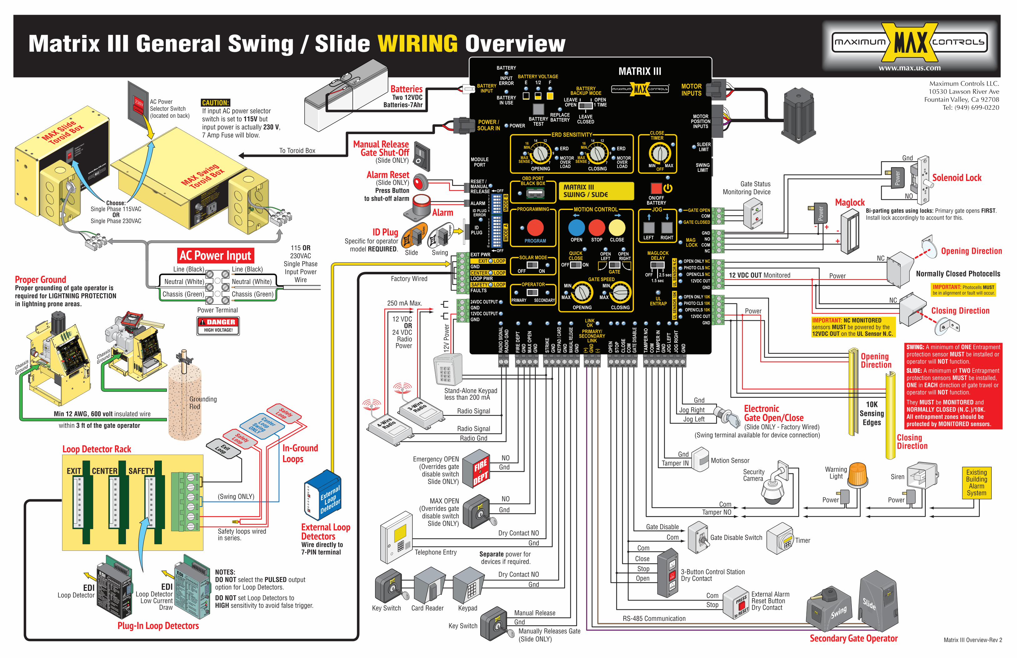
Matrix III General Swing / Slide WIRING OverviewMaximum Controls LLC.10530 Lawson River Ave
Fountain Valley, Ca 92708Tel: (949) 699-0220
AC Power Input EXIT PWR
ALARM
POWER /SOLAR IN
BATTERYINPUT
OPENING CLOSING
CLOSINGOPENING
ERD
OBD PORTBLACK BOX
PROGRAMMING
SOLAR MODE
PROGRAM
MOTOROVERLOAD
ERD
MOTOROVERLOAD MAX
OFF
MAXSENSE
MAXSENSE
BATTERYBACKUP MODE
ERD SENSITIVITY
MOTION CONTROL
OPEN
GATE SPEED
MAGLOCK
ULENTRAP
PRIMARY/SECONDARY
LINK
STOP CLOSE
MOTORINPUTS
CLOSETIMER
MAGLOCKDELAY
JOG
BATTERYTEST
INPUTERROR
BATTERY
BATTERYIN USE
REPLACEBATTERY LEAVE
CLOSED
LEAVEOPEN
OPEN1 TIME
BATTERY VOLTAGEE F1/2
RESET /MANUALRELEASE
IDPLUG
LINKOK
MODULEPORT
MOTORPOSITIONINPUTS
SLIDERLIMIT
SWINGLIMIT
GND
OPEN ONLY NC
OPEN ONLY 10K
PHOTO CLS NCOPEN/CLS NC
GND12VDC OUT
GND
GND
GND
GND
GND
GND
JOG
RIGH
TJO
G LE
FT
TAMP
ER IN
TAMP
ER N
O
GATE
DISA
BLE
MANU
AL RE
LEAS
E
KEYP
AD / C
ARD
GND
(-)(+)
GND
GND
MAX
OPEN
FIRE
DEP
T
RADI
O GN
DRA
DIO
SIGNA
L
STRI
KE
CLOS
ECO
M
COM
STOP
OPEN
PHOTO CLS 10KOPEN/CLS 10K
12VDC OUT
NOCOM
NC
ID PLUGERROR
24VDC OUTPUT
12VDC OUTPUT
GND
GND
GND
LOOP PWROFF
PRIMARY
LEFT
ON/OFFBATTERY
RIGHT
SECONDARY
ON
QUICKCLOSE
OPENLEFT
OPEN RIGHT
GATEOFF
123456789
10
123456
MIN MIN
MAX MAX
ON
OFF 2.5 sec1.5 sec
FAULTSOPERATOR
MATRIX III
OFF
OFF
3
1
1416
MIN16
MIN12
9
73
1
14 12
9
7
UL S
ENSO
R N.
C.UL
SEN
SOR
10K
POWER
MODE
AMO
DE B
EXIT LOOP
LOOP
LOOP
CENTER
SAFETY
GATE OPENCOM
GATE CLOSED
MIN
MATRIX IIISWING / SLIDE
230V
SAFETYCENTEREXIT
ElectronicGate Open/Close(Slide ONLY - Factory Wired)
Secondary Gate Operator
Factory Wired
Loop Detector Rack
Plug-In Loop Detectors
Card Reader
Separate power fordevices if required.
KeypadKey Switch
Telephone Entry
Emergency OPEN(Overrides gatedisable switch
Slide ONLY)
MAX OPEN(Overrides gatedisable switch
Slide ONLY)
Stand-Alone Keypadless than 200 mA
Dry Contact NO
Dry Contact NO
NO
NO
Radio Signal
Radio Signal
12V
Pow
erRadio Gnd
12 VDCOR
24 VDCRadioPower
250 mA Max.
4-WireRadio
3-WireRadio
Stop
StopClose
Open
Tamper NO
Tamper IN
Com
Com
Com
Gate Disable
Com
Gnd
Gnd
Gnd
Gnd
Gnd
Gnd
Gnd
NO
+
+
- -
NC
12 VDC OUT Monitored
Power
Power
NC
Jog RightJog Left
External AlarmReset ButtonDry Contact
PRESS
to RESET
ID PlugSpecific for operator
model REQUIRED.
Maglock
Motion Sensor
Opening Direction
SecurityCamera
Gate Disable SwitchON
OFF
SirenWarning
Light
PowerPower
Pow
er
ExistingBuildingAlarm
System
Timer
Normally Closed Photocells
Closing Direction
OpeningDirection
ClosingDirection
10KSensingEdges
IMPORTANT: NC MONITORED sensors MUST be powered by the 12VDC OUT on the UL Sensor N.C.
IMPORTANT: Photocells MUST be in alignment or fault will occur.
GATE OPEN
GATE CLOSED
Gate StatusMonitoring Device
Pow
er
EDILoop Detector
ON
12
34
56
78
5 = Optimum Sens.
= Increase Sens.
= Decrease Sens.
DEFLECTOMETER
POWERON = Normal Power
OFF= No Power
LED INDICATORSDETECTON = DetectOFF= No Detect
2 Hz Flash=Delay Timing
SW1 SW2 Frequency
ON ON = Low
ON OFF = Medium-Low
OFF ON = Medium-High
OFF OFF = HighSW4 SW5 Output B
ON ON = Pulse on Entry
ON OFF = B same as A
OFF ON = Pulse on Exit
OFF OFF = Loop Fault
SW3ON = Fail Secure
OFF = Fail Safe
SW6ON = 2 Second Delay
OFF = No Delay
SW7ON = Normal Presence
OFF = Infinite Presence
SW8ON = Sensitivity Boost
OFF = No Sensitivity Boost
Loop Fault1 Flash = Open Loop
2 Flashes= Shorted Loop
3 Flashes=25% change
of Inductance
Both LED’s Flashing=
Current Loop Fault
PWR LED Flashing=
Previous Loop Fault
EDITel: 480.968.6407
DEFLECTOMETER
SENS
RESET
POWER
DETECTEDI
SENSLMA1800
OPTIONS
12
34
56
78
ON
EDILoop Detector
Low CurrentDraw
OPTIONS
ON
12
34
56
78
5 = Optimum Sens.
= Increase Sens.
= Decrease Sens.
DEFLECTOMETER
POWERON = Normal Power
OFF= No Power
LED INDICATORSDETECTON = DetectOFF= No Detect
2 Hz Flash=Delay Timing
SW1 SW2 Frequency
ON ON = Low
ON OFF = Medium-Low
OFF ON = Medium-High
OFF OFF = HighSW4 SW5 Output B
ON ON = Pulse on Entry
ON OFF = B same as A
OFF ON = Pulse on Exit
OFF OFF = Loop Fault
SW3ON = Fail Secure
OFF = Fail Safe
SW6ON = 2 Second Delay
OFF = No Delay
SW7ON = Normal Presence
OFF = Infinite Presence
SW8ON = Sensitivity Boost
OFF = No Sensitivity Boost
Loop Fault1 Flash = Open Loop
2 Flashes= Shorted Loop
3 Flashes=25% change
of Inductance
Both LED’s Flashing=
Current Loop Fault
PWR LED Flashing=
Previous Loop Fault
EDITel: 480.968.6407
DEFLECTOMETER
SENS
RESET
POWER
DETECTEDI
SENSLMA1800-LP
12
34
56
78
ON
3-Button Control StationDry Contact
Solenoid Lock
Bi-parting gates using locks: Primary gate opens FIRST. Install lock accordingly to account for this.
External LoopDetectorsWire directly to7-PIN terminal
NOTES:DO NOT select the PULSED outputoption for Loop Detectors.
DO NOT set Loop Detectors toHIGH sensitivity to avoid false trigger.
DANGERHIGH VOLTAGE!
Line (Black)
Neutral (White)
Chassis (Green)
Line (Black)
Neutral (White)
Chassis (Green)
Power Terminal
To Toroid Box
115 OR230VAC
Single PhaseInput Power
Wire
Choose:Single Phase 115VAC
ORSingle Phase 230VAC
CAUTION: If input AC power selector switch is set to 115V but input power is actually 230 V, 7 Amp Fuse will blow.
Alarm Reset(Slide ONLY)Press Button
to shut-off alarm
Alarm
Manual ReleaseGate Shut-Off
(Slide ONLY)
BatteriesTwo 12VDC
Batteries-7Ahr
External
Loop
Detector
FUSE7 Amp
POWER
115VAC 3A maxOn
Off
WARNING: For continued protection
against fire, re
place only with the
same type and rating of fuse.
AVERTISSEMENT: pour ne pas
compromettre la protection contre les
risques d’incendie, utiliser un fusible
de mêmes type et caractéristiques
nominales.
MAX Swing
Toroid BoxAC
IN FUSE
7 AmpPOWER
On
Off
www.Max.US.com
MAX Toroid 15 Amp
Select Input
Voltage
115VAC or
230VAC115V
MAX Slide
Toroid Box
AC PowerSelector Switch(located on back)
RS-485 Communication SwingSlide
Key Switch GndManual Release
Manually Releases Gate(Slide ONLY)
Proper GroundProper grounding of gate operator is required for LIGHTNING PROTECTION in lightning prone areas.
GroundingRod
WARNINGconnect chassis
to ground rod for
lightning protection
LIMIT
SENSOR
E1/2
Replace
Battery
ON/OFF
Battery
TEST
Battery
Battery IN
Error
F
Battery Module
SAFETYSAFETY
CENTERCENTER
EXIT
EXIT
EXIT PWR
ALARM
POWER /
SOLAR IN
BATTERY
INPUT
OPENING
CLOSING
CLOSING
OPENING
ERD
OBD PORT
BLACK BOX
PROGRAMMING
SOLAR MODEPROGRAM
MOTOR
OVERLOAD
ERDMOTOR
OVERLOAD
MINMAX
OFF
MAXSENSE
MAXSENSE
BATTERY
BACKUP MODE
ERD SENSITIVITY
MOTION CONTROL
OPEN
GATE SPEED
MAGLOCK
ULENTRAP
PRIMARY/
SECONDARY
LINK
STOPCLOSE
MOTOR
INPUTS
CLOSE
TIMER
MAGLOCK
DELAY
JOG
BATTERY
TEST
BATTERY
INPUT
ERROR
BATTERY
IN USEREPLACE
BATTERY
LEAVE
CLOSEDLEAVE
OPEN
OPEN1 TIME
BATTERY VOLTAGE
E
F1/2
MANUAL
RELEASE /
RESET
IDPLUG
LINKOK
MODULE
PORT
MOTOR
POSITION
INPUTS
SLIDER
LIMIT
SWING
LIMIT
GND
GND
GND
GND GN
D
GND
GND JO
G LE
FTJO
G RI
GHT
TAMP
ER IN
TAMP
ER N
OGA
TE D
ISAB
LE
MANU
AL R
ELEA
SEKE
YPAD
/ CAR
D
GND (-)
(+)
GND GN
DMA
X OP
ENFI
RE D
EPT
RADI
O GN
DRA
DIO
SIGN
AL
STRI
KE
CLOS
E
COM
COM
STOP
OPEN
NO
NC
ID PLUG
ERROR
24VDC OUTPUT
12VDC OUTPUT
GND
GND
GND
LOOP PWR
OFF
PRIMARY
LEFT
ON/OFF
BATTERY
RIGHT
SECONDARY
ON
QUICK
CLOSE
OPENLEFT
OPENRIGHT
GATE
ON12345678910 OFF
123456
MIN
MIN
MAX
MAX
OFF
OFF2.5 sec
1.5 sec
FAULTS
OPERATOR
MATRIX III
OFF
MIN
3
1
14
16
MIN16
12
9
7
3
1
1412
9
7
UL S
ENSO
R N.
C.
UL S
ENSO
R 10
K
POWER
MODE
A
MODE
B
EXITLOOP
LOOP
SAFETYCENTER
SAFETY
GATE OPENCOM
GATE CLOSED
MAXIMUM CONTROLS
SWINGER / SLID
ER Select Input Voltage 115VAC or 230VAC
AC
IN
www.Max.US.com
MAX Megatron Toroid
115
EXIT PWR
ALARM
POWER /
SOLAR IN
BATTERY
INPUT
OPENING
CLOSING
CLOSING
OPENING
ERD
OBD PORT
BLACK BOX
PROGRAMMING
SOLAR MODEPROGRAM
MOTOR
OVERLOAD
ERD
MOTOR
OVERLOAD
MINMAX
OFF
MAX
SENSE
MAX
SENSE
BATTERY
BACKUP MODE
ERD SENSITIVITY
MOTION CONTROL
OPEN
GATE SPEED
MAGLOCK
UL
ENTRAP
PRIMARY/
SECONDARY
LINK
STOPCLOSE
MOTOR
INPUTS
CLOSE
TIMER
MAGLOCK
DELAY
JOG
BATTERY
TEST
BATTERY
INPUT
ERROR
BATTERY
IN USE
REPLACE
BATTERY
LEAVE
CLOSEDLEAVE
OPEN
OPEN
1 TIME
BATTERY VOLTAGE
E
F
1/2
MANUAL
RELEASE /
RESET
IDPLUG
LINKOK
MODULE
PORT
MOTOR
POSITION
INPUTS
SLIDER
LIMIT
SWING
LIMIT
GND
OPEN ONLY NC
OPEN ONLY 10K
PHOTO CLS NC
OPEN/CLS NC
GND12VDC OUT
GND
GND
GND GN
D
GND
GND JO
G LE
FTJO
G RI
GHT
TAMP
ER IN
TAMP
ER N
O
GATE
DIS
ABLE
MANU
AL R
ELEA
SE
KEYP
AD / C
ARD
GND (-)
(+)
GND GN
DMA
X OP
EN
FIRE
DEP
T
RADI
O GN
DRA
DIO
SIGN
AL
STRI
KE
CLOS
ECO
M
COM
STOP
OPEN
PHOTO CLS 10K
OPEN/CLS 10K
12VDC OUT
NO
COM
NC
ID PLUG
ERROR
24VDC OUTPUT
12VDC OUTPUT
GND
GND
GND
LOOP PWR
OFF
PRIMARY
LEFT
ON/OFF
BATTERY
RIGHT
SECONDARY
ON
QUICK
CLOSE
OPENLEFT
OPEN
RIGHT
GATE
ON123456789
10 OFF
123456
MIN
MIN
MAX
MAX
OFF
OFF2.5 sec
1.5 sec
FAULTS
OPERATOR
MATRIX III
OFF
MIN
3
1
14
16
MIN16
12
9
7
3
1
1412
9
7
UL S
ENSO
R N.
C.
UL S
ENSO
R 10
K
POWER
MODE
AMO
DE B
EXITLOOP
LOOP
SAFETYCENTER
SAFETY
GATE OPENCOM
GATE CLOSED
MAXIMUM CONTROLS
SWINGER / SLID
ER
EXIT
CENTER
SAFETY
Chassis
Ground
Chassis
Ground
Min 12 AWG, 600 volt insulated wire
within 3 ft of the gate operator
In-GroundLoops
Safety loops wiredin series.
CenterLoopSwingONLY
SafetyLoop
SafetyLoopExitLoop
(Swing ONLY)
(Swing terminal available for device connection)
SWING: A minimum of ONE Entrapment protection sensor MUST be installed or operator will NOT function.SLIDE: A minimum of TWO Entrapment protection sensors MUST be installed, ONE in EACH direction of gate travel or operator will NOT function.
They MUST be MONITORED and NORMALLY CLOSED (N.C.)/10K.All entrapment zones should be protected by MONITORED sensors.
Slide Swing
Swin
ger
Slid
er
Matrix III Overview-Rev 2