Embed Size (px)
Citation preview

M AT R I X® 4 3 0 U S E R M A N U A L
Entry level guidance Software version 1.03

GETTING STARTED1. Power on the console.
Setup machine2. On guidance screen, press NAVIGATION AND GUIDANCE
OPTIONS tab to display options.3. Press HOME button .4. Press CONSOLE button .
►LCD Brightness ►Color scheme ►Units ►GNSS demo mode
►Screenshot ►Time zone ►Console information
5. Press HOME button .6. Press CONFIGURATION button .
►Machine Configuration ►Lightbar spacing ►GNSS
Setup guidance7. From the Home screen, press GUIDANCE button .8. On guidance screen, press NAVIGATION AND GUIDANCE
OPTIONS tab to display options.►Guidance mode – Straight AB guidance ,
Curved AB guidance , Circle pivot guidance , Last pass guidance or no guidance
►Create AB guideline A B►Create boundary ►Set return point
Start mapping9. Press VEHICLE icon in the center of the guidance screen to
turn on or off application mapping.
Guidance screen includes►Selectable information – Speed , total applied
area , application time or swath number ►Lighbar and Navigation Activity – GNSS status, cross track
error or current activity►Status Bar – GNSS , guidance mode ,
boundary area and Application mapping status ►A+ nudge feature A►Transport mode ►Zoom
Start new jobTo start a new job, delete old job data.
1. From the Home screen, press DATA button .2. Press RECYCLE button .
A
A
#2
#3
#4
#6
#8
#9

198-05332 R1 EN
Matrix® 430MATRIX 430 CONSOLE
GNSS antenna connection
Power connection
Integrated RAM mount (assembly required)
Power button
USB port with rubber cover
Standard RAM bracket(assembly required)
Bright touch screen
System components
Connect +12v at 15/30Connect GND to 31
Power Cable45-05867DC:xx/xx
Console, Matrix 430 CG430-GLO
Kit, RAM Mount w/ Suction Cup
Power Cable45-05645DC:xx/xx
Connect to+12v Only
POWER CABLE45-05775DC: XXXX
CAUTION CONN. TO+12V ONLY
GPS Patch Antenna
RXA-30 Antenna
Power Cables
Power/Sense/Speed Cables
Direct to Battery 45-05775
Lighter Adapter 45-05645
US 45-05970
EU 45-05969
COBO Adapter 45-05867
Status On/OffSENSE
+12v
GPS Speed
POWER IN
Power/Sense/Speed
45-05970 xx/xx
Power/Sense/Speed
45-05969 xx/xx
POWER IN
Work On-Off
GPS Speed
All changes are saved automatically.The console needs to be cycled off and back on when changing or attaching equipment to the Matrix 430 system.
Recommended antenna installationThe GNSS antenna should be mounted as far forward as possible on top of the cab on a metal surface of at least 4”/10 cm square.
Power on1. Press POWER button .
Power off1. Press POWER button .2. Select from:
►Accept – to continue shut down►Cancel – to keep the console on.
WARNING! Wait 30 seconds before restarting the console after powering off.
2 www.teejet.com
Matrix® 430ICON REFERENCE
Guidance
Selectable information
Speed
Total applied area
Application time
Swath number
Show nothing
A B Mark A , Mark B
A A+ nudge feature
Transport Mode
Navigation and guidance options tab
Home
Guidance modes
Straight AB guidance
Curved AB guidance
Circle pivot guidance
Last pass guidance
No guidanceApplication boundary
Start
Finish
Cancel
DeleteReturn to point
Mark
Go to point
Cancel
Delete
Close options
Zoom in/out
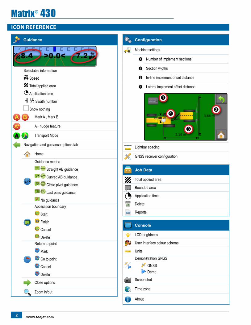
Configuration
Machine settings
Number of implement sections
Section widths
In-line implement offset distance
Lateral implement offset distance
Lightbar spacing
GNSS receiver configuration
Job Data
Total applied area
Bounded area
Application time
Delete
ALL Reports
Console
LCD brightness
User interface colour scheme
Units
Demonstration GNSS
GNSS Demo
Screenshot
Time zone
About

398-05332 R1 EN
Matrix® 430KEYBOARD ENTRY SCREENS
To change a value:1. Press CURRENT VALUE.2. Use the numeric keypad to enter a new value.3. Select from:
►Accept – to save the settings►Cancel – to leave the keypad without saving
Figure 1: Example of keyboard
(m)
1 2 3
3.66
Clear
4 5 6 <--
7 8 9
0 . +/-
HOME
Guidance Used to view a computer-generated image of the vehicle position displayed in the application area. From this screen all setup and navigation options can be accessed via the tab on the right side of the screen.
Configuration Used to setup the machine settings, lightbar and GNSS receiver.
Job dataUsed to view or delete job data and export reports.
Console Used to setup LCD brightness, colour scheme, units, screenshot and time zone; start demonstration GNSS; and view console information.
Calculator
A

4 www.teejet.com
Matrix® 430GUIDANCEThe Guidance Screen creates a computer-generated image of the vehicle position displayed in the application area. From this screen
all setup and navigation options can be accessed via the tab on the right side of the screen.
Status bar
Guidance bar
Painted coverage area
Overlap coverage area
Navigation guidelines
Vehicle with real-time representation of active boom sections
Navigation and guidance options tab
Navigation and guidance options tabHome – used to access Home screenGuidance Modes – select one of five (5) guidance modes: Straight AB guidance , Curved AB guidance , Circle pivot guidance , Last pass guidance , No guidance
Application Boundary – create or delete a boundary
Return to Point – create, guide to or delete a pointClose menu – used to close the Navigation and guidance options menu
Zoom In/Out – adjust the vehicle’s view or perspective to the horizon from vehicle view to bird’s eye view
Guidelines A – establish an AB guideline or shift line to the vehicle’s current locationTransport mode – when enabled, all operation functions are locked off and cannot be activated.
A
On screen guidance• Guidelines:
◄Orange – active guidance line ◄Brown (multiple) – adjacent guidance lines ◄Black – boundary line
• Points – markers for established points: ◄Red point – Return to point ◄Blue point – Mark A ◄Green point – Mark B
• Coverage area – illustrates applied area and overlap: ◄Blue – one application ◄Red – two or more applications
• Zoom in/out & perspective – adjusts the vehicle’s view or perspective to the horizon from vehicle view to bird’s eye view.
• Boom Sections: ◄Empty box – inactive boom ◄White box – active boom
Status barThe status bar provides information on GNSS status, guidance mode, boundary area, and implement control status.
GNSS statusGuidance mode
Bounded area statusApplication mapping status

598-05332 R1 EN
Matrix® 430GNSS status
Red = no GNSS
GPS only
Green = DGPS,WAAS/RTK, GLONASS
Guidance mode
Straight AB guidance
Curved AB guidance
Circle pivot guidance
Last pass guidance
No icon = no guidance
Bounded area status
Outside boundary = currently traveling outside bounded area
Inside boundary = currently traveling inside bounded area
No icon = no boundary established
Application mapping status
Red = off
Green = on
Status/information screens
To display information:1. Press status bar icon.
►GNSS status – displays information regarding number of satellites in view, satellite quality and receiver ID
►Bounded area status – displays information regarding the area in the current boundary
To remove the information box, tap the information box.
Guidance barThe guidance bar keeps you informed of your choice of selectable information (current speed, total applied area, application time, swath number) and navigation activity (cross track error, current activity and GNSS status).
Lightbar & Navigation ActivitySelectable Information Selectable Information
Lighbar & navigation activityLightbar spacing – used to represent the distance away from the guideline or vehicle.GNSS status – displays flashes “GPS” when GNSS is unavailableCross track error – displays the distance from your desired guidelineCurrent activity – displays activities such as mark an A or B point and distance to return to a marked point
Selectable informationSpeed – displays the current speed of travelTotal applied area – displays the total accumulated area that has had application applied including double coverage areasApplication time – displays the total time application is active during the current job
Swatch number – displays the current swath number in reference to the initial guidance line. Number will be shown as a positive number when the vehicle is to the right of the AB baseline or a negative number when the vehicle is to the left of the AB baseline
1 2 3 4 5 6-6 -5 -4 -3 -2 -1
No information – shows no information in the display area

6 www.teejet.com
Matrix® 430Guidance Modes
To choose a Guidance Mode:1. Press NAVIGATION AND GUIDANCE OPTIONS tab to display
navigation options.2. Press GUIDANCE MODE button .3. Select from:
►Straight AB guidance ►Curved AB guidance ►Circle pivot guidance ►Last pass guidance ►No guidance
NOTE: Offset to adjacent guidelines will be calculated using the guidance width, which is encoded in Machine setup in the Configuration options.
Straight AB guidanceStraight AB guidance provides straight line guidance based on A and B reference points. The original A and B point are used to calculate all other parallel guidelines.
No guidanceNo guidance turns off guidance.
NOTE: No guidance mode does not delete established guide lines or points from the console. To delete established/saved data from the console, please refer to the Data management section under Unit setup.
Last pass guidanceLast pass guidance offers true last pass navigation. The console will automatically detect the nearest applied area and establish parallel guideline based on that area.
NOTE: If a boundary is established but no application occurred during the boundary process, guidance will not initiate.
Curved AB guidanceCurved AB guidance provides guidance along curved lines based on an initial AB reference line. This initial baseline is used to calculate all other guidelines.
NOTE: Curved guidance is recommended not to exceed 30° within the AB guideline.
HINT: While working in a bounded area, the guidance pattern extending beyond the established AB points will be straight line guidance.
Circle pivot guidanceCircle pivot guidance provides guidance around a central location that radiates inward or outward based on an initial AB reference line. This initial baseline is used to calculate all other guidelines.It is used for product application in a centre pivot field while being guided along a circular guideline that matches a centre pivot irrigation system radius.

798-05332 R1 EN
Matrix® 430A Guidelines
A B Marking A and B points
To establish an AB guideline:1. Drive to the desired location of Point A .2. While the vehicle is in motion, press MARK A icon A . NOTE: a Mark A button A is also available on the Navigation
and guidance options menu3. Drive to the desired location of Point B .4. Press MARK B button B to establish the AB line.The console will begin providing navigation information.
NOTE: The MARK B Icon B is not available for selection (greyed out) until the minimum distance is travelled (3.0 metres in Straight or Curved guidance, 50.0 metres in Circle pivot guidance).
It is not necessary to drive the entire circumference of the centre pivot in order to initiate Circle pivot guidance.
Use CANCEL MARK button on the Navigation and guidance options menu to cancel the Mark A command and revert to the previous guideline (when established).
A A+ nudge featureThe A+ nudge feature allows the current guideline to be shifted to the vehicle’s current location.
To adjust the guideline:1. Press NAVIGATION AND GUIDANCE OPTIONS tab to display
navigation options.2. Press A+ NUDGE button A .
A

8 www.teejet.com
Matrix® 430Application Boundary
Application boundaries establish areas where application is and is not to be applied. Boundaries can be established in all guidance modes. One exterior boundary can be stored at a time.In correspondence to your current location, the IN BOUNDARY icon or OUT BOUNDARY icon is displayed on the status bar once the boundary is established.
Creating a boundaryTo establish an application boundary:1. Drive to a desired location at the perimeter of the field/
application area.2. Press NAVIGATION AND GUIDANCE OPTIONS tab to display
navigation options.3. Press BOUNDARY button .4. While the vehicle is in motion, press BOUNDARY button .5. Travel the perimeter of the field/area.6. Finish boundary:
►Travel to within one swath width of the starting point. The boundary will close automatically (the white boundary line will turn black)
►Press BOUNDARY FINISH button . A straight line will complete the boundary between your current location and the starting point
NOTE: The BOUNDARY FINISH button is not available for selection (greyed out) until the minimum distance is travelled (five-times the swath width).
Use CANCEL BOUNDARY button under Boundary on the Navigation and guidance options menu to cancel the new field boundary process and revert to the previous boundary (when established).
Delete the boundaryTo delete the established boundary:1. Press NAVIGATION AND GUIDANCE OPTIONS tab to display
navigation options.2. Press BOUNDARY button .3. Press DELETE BOUNDARY button .

998-05332 R1 EN
Matrix® 430Return to Point
Return to point provides guidance back to an established point. An arrow directs the vehicle back to the established point.A return point will remain active until deleted.
Marking a return pointTo mark a return point:1. Drive to the desired location of return point .2. Press NAVIGATION AND GUIDANCE OPTIONS tab to display
navigation options.3. Press RETURN TO POINT button .4. Press ADD POINT button .
Delete the return pointTo delete the established return point:1. Press NAVIGATION AND GUIDANCE OPTIONS tab to display
navigation options.2. Press RETURN TO POINT button .3. Press DELETE POINT button .Delete point button is not available while return to point guidance is active.
Guidance to a return pointTo show distance and guidance to the established return point:1. Press NAVIGATION AND GUIDANCE OPTIONS tab to display
navigation options.2. Press RETURN TO POINT button .3. Press RETURN TO POINT GUIDANCE button .The console will begin providing the distance information on the guidance bar from the vehicle to the established point.
Use CANCEL RETURN TO POINT GUIDANCE button under Return to point on the Navigation and guidance options menu to hide distance and guidance to the established point.Guidance cannot be calculated when “?” appears in the guidance bar.
Zoom In/OutZoom in/out & perspective is used to adjust the vehicle’s view or perspective to the horizon from vehicle view to bird’s eye view.
• Zoom in will adjust view to vehicle view displaying a compass on the horizon
• Zoom out will adjust view to bird’s eye view

10 www.teejet.com
Matrix® 430Application Mapping & Applied alert
Application mapping is used to map coverage areas and flash and sound alerts when entering and existing previously mapped applied areas to alert the operator to turn on or shut off application.
NOTE: Application mapping does not control actual application.
Mapping with console onlyTo switch mapping and alerts off or on using the console:1. Press vehicle in the center of the screen.
◄Mapping and alerts on – status bar icon will change to green ◄Mapping and alerts off – status bar icon will change to red
Mapping with work on/off switchWhen installed, the work on/off switch should remain in the “off” position for all setup options.
To switch mapping and alerts off or on using the switch:1. Turn the switch to the “On” or "Off" position.
◄Mapping and alerts on – status bar icon will change to green ◄Mapping and alerts off – status bar icon will change to red
To switch mapping and alerts off or on using the console while a switch is attached:1. Turn the switch to the "Off" position. 2. Press vehicle in the center of the screen.
◄Mapping and alerts on – status bar icon will change to green ◄Mapping and alerts off – status bar icon will change to red
Applied alertWhen entering or exiting an applied area, an audio alert will sound and section indicators will flash as each section needs to be turned on/off.
◄Two beeps – entering an applied area; section mapping will turn off
◄One beep – exiting an applied area; section mapping will turn on

1198-05332 R1 EN
Matrix® 430Transport Mode
Transport mode is recommended for use when traveling between fields as this will improve accuracy in guidance functions. To enable Transport Mode:1. Press the Transport Mode button .
◄When enabled, all guidance functions are disabled.
To disableTransport Mode:1. Press the Guidance button . NOTE: There will be a slight delay while exiting Transport Mode.
CONFIGURATION
Machine settings1. From the Home screen, press CONFIGURATION button .2. Press MACHINE CONFIGURATION button .3. Press current value and use the keyboard to enter a new value.
►Number of implement sections – used to select the number of implement sections. Range is 1 to 7 sections.
►Section widths – used to enter the width of each section. Each section can be a different width. Range for each section is 0.0 to 246.06 feet / 0.0 to 75.0 metres. Total for all sections must be greater than 3.28 feet / 1.0 metre.
►In-line implement offset distance – used to define the in-line distance from the GNSS antenna to the implement. Range is 0.0 to 164.04 feet / 0.0 to 50.0 metres.
►Lateral implement offset distance – used to define the lateral distance from the center line of the machine to the center of the implement. While facing in the machine's forward direction:◄Right of center – use a positive value ◄Left of center – use a negative value Range is 0.0 to +/-32.8 feet / 0.0 to +/-10.0 metres.

12 www.teejet.com
Matrix® 430Lightbar spacing
Lightbar spacing is used to set the distance away from the guideline or vehicle each guidance screen lightbar box represents.
1. From the Home screen, press CONFIGURATION button .2. Press LIGHTBAR SPACING button .3. Press current value and use the keyboard to enter a new value.
GNSS receiver configurationUsed to configure GNSS receiver type.
1. From the Home screen, press CONFIGURATION button .2. Press GNSS button .3. Select:
►GPS – uncorrected signals from the GPS system►SBAS (e.g. EGNOS, GAGAN, MSAS, SDCM, WAAS) – adds
differentially corrected signals from the SBAS system►GLONASS – adds uncorrected signals from the GLONASS
system
JOB DATA Job Information provides an overview of job information including the total applied area, total time traveled and bounded area.
1. From the Home screen, press DATA button .►Total applied area ►Bounded area
NOTE: bounded area is only shown when a boundary is active.
►Application time
Delete job dataTo start a new job, delete job data from internal storage:
1. Press DATA button .2. Press RECYCLE button .3. Select ACCEPT icon or CANCEL icon accordingly.

1398-05332 R1 EN
Matrix® 430ALL Reports
To save reports to a USB drive:
1. Press DATA button .2. Insert USB drive.3. Press SAVE ALL button ALL .NOTE: If no data has been collected, the SAVE ALL button will be
unavailable (grayed out).
2011-10-2019:30(7:30pm)
0:36 6.9(ha) 6.9(ha)
+45.6389-111.3946
www.teejet.com Matrix430©2014TeeJetTechnologies.Softwareversion:1.01e 1
CONSOLE
The Console setup is used to configure the display and cultural settings.
1. From the Home screen, press CONSOLE button .2. Select from:
►LCD brightness – used to adjust the brightness of the console display
►Colour scheme – used to change the background and text colours on the display
►Units – used to define the system measurements►Demo mode – used to start playback of simulated GNSS
data◄GNSS – press to use real GNSS signals◄Demo – press to start demonstration GNSS
►Screenshot – used to allow screen captures to be saved to a USB drive
►Time zone – used to establish the local time zone►About – used to display the system software version

www.teejet.com
M AT R I X® 4 3 0U S E R M A N U A L
98-05332-EN-LT R1 English © TeeJet Technologies 2016
FIRST START-UP CONSOLE CONFIGURATIONThe first time the console is started a sequence of configuration settings will be presented:
Units►Select system measurements units
Machine settings►Set Number of implement sections ►Set Section widths ►Set In-line implement offset distance ►Set Lateral implement offset distance
GNSS Receiver ConfigurationThe GNSS configuration menu allows the user selection of GPS, GLONASS, or SBAS when using the internal receiver. When operating under a supported SBAS system, the receiver will apply SBAS corrections to the 8 strongest GPS observations, and in addition will included up to for GLONASS observations to the solution. Select from:
◄GPS – uncorrected signals from the GPS system
◄SBAS (e.g. EGNOS, GAGAN, MSAS, SDCM, WAAS) – adds differentially corrected signals from the SBAS system
◄GLONASS – adds uncorrected signals from the GLONASS system
mileft.in.
kmmcm
Copyrights© 2016 TeeJet Technologies. All rights reserved. No part of this document or the computer programs described in it may be reproduced, copied, photocopied, translated, or reduced in any form or by any means, electronic or machine readable, recording or otherwise, without prior written consent from TeeJet Technologies.
TrademarksUnless otherwise noted, all other brand or product names are trademarks or registered trademarks of their respective companies or organizations.
Limitation of LiabilityTEEJET TECHNOLOGIES PROVIDES THIS MATERIAL “AS IS” WITHOUT WARRANTY OF ANY KIND, EITHER EXPRESSED OR IMPLIED. NO COPYRIGHT LIABILITY OR PATENT IS ASSUMED. IN NO EVENT SHALL TEEJET TECHNOLOGIES BE LIABLE FOR ANY LOSS OF BUSINESS, LOSS OF PROFIT, LOSS OF USE OR DATA, INTERRUPTION OF BUSINESS, OR FOR INDIRECT, SPECIAL, INCIDENTAL, OR CONSEQUENTIAL DAMAGES OF ANY KIND, EVEN IF TEEJET TECHNOLOGIES HAS BEEN ADVISED OF SUCH DAMAGES ARISING FROM TEEJET TECHNOLOGIES SOFTWARE.