Embed Size (px)
Citation preview
Abstract—This paper appraises the performances of
two control scenarios, for doubly fed induction generator
(DFIG) operating in wind generation system (WGS),
which are the direct decoupled control (DDC) and indirect
decoupled control (IDC). Both control scenarios studied
combines vector control and Maximum Power Point
Tracking (MPPT) control theory so as to maximize the
captured power through wind turbine. Modeling of DFIG
based WGS and details of both control scenarios have been
presented, a proportional integral controller is employed
in the active and reactive power control loops for both
control methods. The performance of the both control
scenarios in terms of power reference tracking and
robustness against machine parameters inconstancy has
been shown, analyzed and compared, which can afford a
reference to the operators and engineers of a wind farm.
All simulations have been implemented via
MATLAB/Simulink.
Keywords—DFIG, WGS, DDC, IDC, vector control,
MPPT.
I. INTRODUCTION
N recent years, the use of renewable energy sources have
enticed the serious interest because reserves of conventional
sources energy are limited and a number of problems related
with their employment raised, such as environment
contamination, enormous grid requirements. Countries of the
whole world are forced for the alternative energy sources such
as solar energy, wind power and small hydro-electric power
[1], the sustainable power sources are one of the promising
future energy sources. All major politicians, decision makers,
leaders of industry and economy recognized worldwide the
great potentials in sustainable energies. This increased the
efforts, principally in developed countries of world, in
research area and new installations employing renewable and
clean energies which are spectacularly accelerating [2].
Nowadays, wind power can contend with any other source of
energy as a free of cost and non-polluting technique of
harnessing natural energy. Recently, intensive research has
* Corresponding author: [email protected] (A. Kasbi)
being carried out more and more in most of the countries and
resulting the various WGS configurations. The most popular
wind system is the grid connected DFIG-based wind turbine.
This variable speed DFIG generator was adopted to improve
the efficiency, power rating, cost benefit effectiveness etc. [3],
[4]. Indeed, this wind system type, using DFIG generator and
two converters in back-to-back mode that connects the rotor of
generator with grid, has many advantages. For example, the
power converters employed are dimensioned to pass just a
fraction of the total generated power and consequently, this
characteristic allows reducing losses in the power electronics
components, maximizing power capture, smoothing the power
transmission and less mechanical stresses [5]. On the other
hand, by dint of the high variability nature of wind speed,
DFIG-based variable speed WGS are a very efficient way for
wind energy gathering [4], because this provides better
flexibility in power conversion and also more stability in
voltage and frequency control in the power systems to which
these generators are connected [6]. In addition to that, due to
variable speed operation, total energy output is much more
important in case of DFIG-based WGS, so the capacity
utilization factor is improved and cost of per unit energy is
reduced [7].
The performances and power generation depends not only
on the DFIG generator, but also the manner in which the
converters in back-to-back mode are controlled. Concerning
this considered wind system, the rotor side converter (RSC)
controls the active power and reactive power produced by the
machine. As the grid side converter (GSC), it controls the DC
bus voltage and power factor grid side [2], [8].
Many researchers [2], [3], [8] have studied the DFIG-based
wind energy conversion system. In this context, the current
paper is focused on the study, modeling and control of WGS
based on a 1.5 MW DFIG. With a view to control the active
and reactive power exchanged between the DFIG-generator
and the grid, an itemized dynamic model of a DFIG generator
based WGS grid-connected is described in the d-q,
synchronous rotating reference frame by controlling the RSC
with methodology of control based on the vector control
approach (stator flux orientation control strategy). The main
objective of control is to obtain the active and reactive
generated powers equal to the reference values. The control of
Matlab/Simulink based modeling and simulation
of decoupled power control for DFIG operating
in wind generation systems
Abdellatif Kasbi*, Abderrafii Rahali
Laboratory of Electronics, Automatics and Biotechnology, Faculty of Sciences, Moulay Ismaïl University,
B.P. 11201, Zitoune, Meknes, Morocco
I
INTERNATIONAL JOURNAL OF MATHEMATICS AND COMPUTERS IN SIMULATION DOI: 10.46300/9102.2020.14.18 Volume 14, 2020
ISSN: 1998-0159 136
this system is applied to achieve the decoupled control of
stator active and reactive powers exchanged among the DFIG-
generator and the grid to ensure a MPPT. Indeed, two control
scenarios are applied to the DFIG as follows: one is DDC that
performs the regulation directly on the powers without taking
into consideration the existing term couplings between the
active and reactive powers, and the other is the IDC which is
done through two cascading loops, an external loop of active
power (reactive power) control and internal loop of rotor
current control in the q axis (d axis). Our system is simulated
and the performances of the both control scenarios are
compared in terms of reference tracking and robustness facing
generator parameters inconstancy. The remainder of this paper
is organized as follows. After the introduction, Section II
presents the dynamics of the variable speed WGS based on
DFIG-generator, it also presents the MPPT control strategy.
The DDC and IDC scenarios based on vector control approach
for control of DFIG-generator are discussed in Section III.
Section IV presents the analysis and performances evaluation
of both control scenarios using the classical proportional-
integral controller by means of real time simulations. Finally
the conclusion is made in Section V.
II. MODELING OF VARIABLE SPEED WGS
DFIG is a typical electric generator used in the generation
applications of the electrical power and more particularly in
wind turbines [9]. The rotor speed of DFIG is varied by
controlling the amount of power transferred to the rotor
through a bi-directional voltage-source back-to-back power
converter. In wind energy applications the system needs a
gearbox to accelerate the turbine rotation into the generator
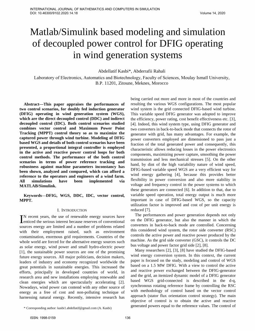
[10]. The clarified schematic configuration of the WGS based
on a DFIG generator studied in this paper is shown in Fig. 1.
In this figure, the mechanical energy is produced by the
turbine and provided to rotor of DFIG via gear box. The stator
winding of the DFIG is directly connected to the grid, whereas
the winding of rotor is fed by back-to-back pulse width
modulation (PWM) converters.
Fig. 1 Configuration of WGS based on DFIG
A. Model of Wind Turbine
In accordance with the Betz theory, the extracted power
through a horizontal axis wind turbine is expressed by [11],
[12]:
𝑃𝑡 = 0.5𝜌𝑆𝑉3𝐶𝑝(, 𝛽) (1)
=t.𝑅
𝑉 (2)
where the air density (ρ = 1.225 kg/m3 at atmospheric
pressure), S the surface swept by turbine blades [m2], V is
wind speed [m/s], Cp is power coefficient, is tip speed
ratio, β the pitch angle [deg], R the blade length [m]. and
t turbine speed [tr/min]. The aerodynamic torque produced by the turbine is
expressed as [12]:
Ct =Pt
t=
0.5ρπR3V2Cp( , β)
(3)
The Gear Box adapts the speed of the turbine to the speed
of the generator; it is modeled by the following mathematical
relations:
Cg =Ct
G , t =
m
G (4)
The following equation models the generator shaft:
𝐽𝑑𝑚
𝑑𝑡= 𝐶𝑚 = 𝐶𝑔 − 𝐶𝑒𝑚 − 𝑓𝑣𝑖𝑠𝑚 (5)
where 𝐽: Total inertia that appears on the shaft of the
generator, 𝐶𝑒𝑚: Torque electromagnetic produced by the
generator, 𝐶𝑔: Torque from the Gear Box, 𝑓𝑣𝑖𝑠: Viscous
friction coefficient, 𝑚 : Mechanical angular speed of the
generator, 𝐶𝑚 : Total mechanical torque on the axis of the
INTERNATIONAL JOURNAL OF MATHEMATICS AND COMPUTERS IN SIMULATION DOI: 10.46300/9102.2020.14.18 Volume 14, 2020
ISSN: 1998-0159 137
generator.
As [13], the approximate expression of the power
coefficient that we used in this paper is shown as:
𝐶𝑝(, 𝛽) = 0.5176( 116
𝑖− 0.4𝛽 − 5) exp (
21
𝑖 ) + 0.0068 (6)
with:
1
𝑖=
1
+0.08𝛽−
0.035
𝛽3+1 (7)
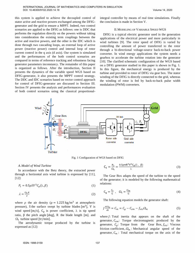
Fig. 2 shows the evolution of the power coefficient in
function of the parameters and β. This curve is characterized
by the optimum point: for the pitch angle β = 0°, it has a
unique maximum point of Cpmax = 0.48 at opt = 8.1; this
value represents the Betz limit, which is the point
corresponding to the maximum power coefficient Cp and
consequently, the most mechanical power can be extracted by
the wind turbine. To conserve at its optimum value and
consequently maximize the captured power, it is necessary to
vary the speed of rotation of the turbine in a linear manner
with the wind speed pursuant to (2).
Fig. 2 Power coefficient in function of tip speed for different Pitch
angle
B. Maximum Wind Power Extraction Strategy
Depending on the wind aerodynamic conditions, there exist
optimal operating points which may allow the extraction of
maximum power. The power captured by the wind turbine can
be substantially maximized by adjusting the coefficient Cp
which represents the turbine efficiency to convert wind kinetic
power into mechanical power and it depends on the rotor
speed of DFIG-generator (i.e., Tip Speed Ratio ). It is
necessary to establish control strategy in order to maximize
the power extracted by adapting the speed of the turbine to an
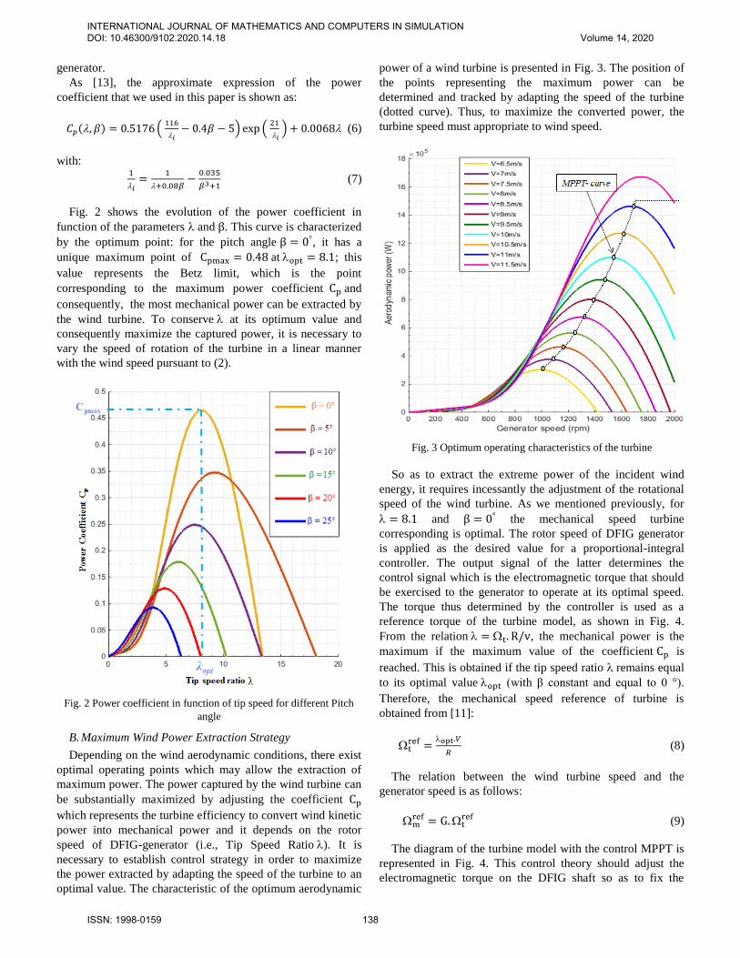
optimal value. The characteristic of the optimum aerodynamic
power of a wind turbine is presented in Fig. 3. The position of
the points representing the maximum power can be
determined and tracked by adapting the speed of the turbine
(dotted curve). Thus, to maximize the converted power, the
turbine speed must appropriate to wind speed.
Fig. 3 Optimum operating characteristics of the turbine
So as to extract the extreme power of the incident wind
energy, it requires incessantly the adjustment of the rotational
speed of the wind turbine. As we mentioned previously, for
= 8.1 and β = 0° the mechanical speed turbine
corresponding is optimal. The rotor speed of DFIG generator
is applied as the desired value for a proportional-integral
controller. The output signal of the latter determines the
control signal which is the electromagnetic torque that should
be exercised to the generator to operate at its optimal speed.
The torque thus determined by the controller is used as a
reference torque of the turbine model, as shown in Fig. 4.
From the relation = t. R/v, the mechanical power is the
maximum if the maximum value of the coefficient Cp is
reached. This is obtained if the tip speed ratio remains equal
to its optimal value opt (with β constant and equal to 0 °).
Therefore, the mechanical speed reference of turbine is
obtained from [11]:
tref =
opt.𝑉
𝑅 (8)
The relation between the wind turbine speed and the
generator speed is as follows:
mref = G.t
ref (9)
The diagram of the turbine model with the control MPPT is
represented in Fig. 4. This control theory should adjust the
electromagnetic torque on the DFIG shaft so as to fix the
INTERNATIONAL JOURNAL OF MATHEMATICS AND COMPUTERS IN SIMULATION DOI: 10.46300/9102.2020.14.18 Volume 14, 2020
ISSN: 1998-0159 138
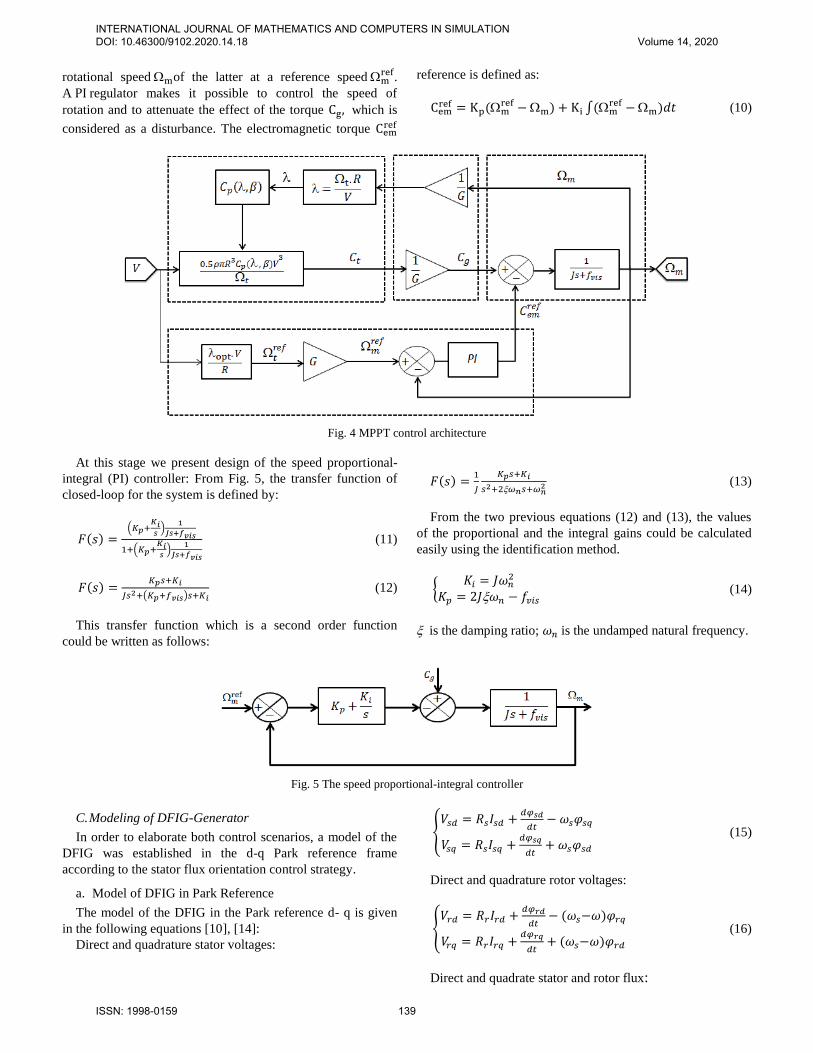
rotational speed mof the latter at a reference speed mref.
A PI regulator makes it possible to control the speed of
rotation and to attenuate the effect of the torque Cg, which is
considered as a disturbance. The electromagnetic torque Cemref
reference is defined as:
Cemref = Kp(m
ref −m) + Ki ∫(mref −m)𝑑𝑡 (10)
Fig. 4 MPPT control architecture
At this stage we present design of the speed proportional-
integral (PI) controller: From Fig. 5, the transfer function of
closed-loop for the system is defined by:
𝐹(𝑠) =(𝐾𝑝+
𝐾𝑖𝑠)
1
𝐽𝑠+𝑓𝑣𝑖𝑠
1+(𝐾𝑝+𝐾𝑖𝑠)
1
𝐽𝑠+𝑓𝑣𝑖𝑠
(11)
𝐹(𝑠) =𝐾𝑝𝑠+𝐾𝑖
𝐽𝑠2+(𝐾𝑝+𝑓𝑣𝑖𝑠)𝑠+𝐾𝑖 (12)
This transfer function which is a second order function
could be written as follows:
𝐹(𝑠) =1
𝐽
𝐾𝑝𝑠+𝐾𝑖
𝑠2+2𝜔𝑛𝑠+𝜔𝑛2 (13)
From the two previous equations (12) and (13), the values
of the proportional and the integral gains could be calculated
easily using the identification method.
𝐾𝑖 = 𝐽𝜔𝑛
2
𝐾𝑝 = 2𝐽𝜔𝑛 − 𝑓𝑣𝑖𝑠 (14)
is the damping ratio; 𝜔𝑛 is the undamped natural frequency.
Fig. 5 The speed proportional-integral controller
C. Modeling of DFIG-Generator
In order to elaborate both control scenarios, a model of the
DFIG was established in the d-q Park reference frame
according to the stator flux orientation control strategy.
a. Model of DFIG in Park Reference
The model of the DFIG in the Park reference d- q is given
in the following equations [10], [14]:
Direct and quadrature stator voltages:
𝑉𝑠𝑑 = 𝑅𝑠𝐼𝑠𝑑 +
𝑑𝜑𝑠𝑑
𝑑𝑡− 𝜔𝑠𝜑𝑠𝑞
𝑉𝑠𝑞 = 𝑅𝑠𝐼𝑠𝑞 +𝑑𝜑𝑠𝑞
𝑑𝑡+ 𝜔𝑠𝜑𝑠𝑑
(15)
Direct and quadrature rotor voltages:
𝑉𝑟𝑑 = 𝑅𝑟𝐼𝑟𝑑 +
𝑑𝜑𝑟𝑑
𝑑𝑡− (𝜔𝑠−𝜔)𝜑𝑟𝑞
𝑉𝑟𝑞 = 𝑅𝑟𝐼𝑟𝑞 +𝑑𝜑𝑟𝑞
𝑑𝑡+ (𝜔𝑠−𝜔)𝜑𝑟𝑑
(16)
Direct and quadrate stator and rotor flux:
INTERNATIONAL JOURNAL OF MATHEMATICS AND COMPUTERS IN SIMULATION DOI: 10.46300/9102.2020.14.18 Volume 14, 2020
ISSN: 1998-0159 139
𝜑𝑠𝑑 = 𝐿𝑠𝐼𝑠𝑑 + 𝐿𝑚𝐼𝑟𝑑𝜑𝑠𝑞 = 𝐿𝑠𝐼𝑠𝑞 + 𝐿𝑚𝐼𝑟𝑞𝜑𝑟𝑑 = 𝐿𝑚𝐼𝑠𝑑 + 𝐿𝑟𝐼𝑟𝑑𝜑𝑟𝑞 = 𝐿𝑚𝐼𝑠𝑞 + 𝐿𝑟𝐼𝑟𝑞
(17)
where 𝐿𝑠, 𝐿𝑟 and 𝐿𝑚stator and rotor per phase winding and
magnetizing inductances, 𝑅𝑠 and 𝑅𝑟 are respectively the
stator and rotor phase resistances; 𝜔 = 𝑝.𝑚 is the electrical
speed and 𝑝 is the pair pole number.
The electromagnetic torque is as follows:
𝐶𝑒𝑚 = 𝑝(𝐼𝑠𝑞𝜑𝑠𝑑 − 𝐼𝑠𝑑𝜑𝑠𝑞) (18)
Stator active and reactive powers are given as:
𝑃𝑠 = (𝑉𝑠𝑑𝐼𝑠𝑑 + 𝑉𝑠𝑞𝐼𝑠𝑞)
𝑄𝑠 = (𝑉𝑠𝑞𝐼𝑠𝑑 − 𝑉𝑠𝑑𝐼𝑠𝑞) (19)
b. Modeling of DFIG with Stator Field Oriented
One can see in (17), the strong coupling between the fluxes
and the currents. Indeed, the electromagnetic torque is the
crossed product between the fluxes and the stator currents,
which makes the control of the DFIG particularly difficult. To
simplify, one should approximate its model to that of the DC
machine which has the advantage of having a natural
decoupling between the flux and the current [15]. For DFIG
machine, the decoupling can be achieved by the flux
orientation technique. The orientation of the flux along the
direct axis of the Park reference is mathematically translated
as follows:
𝜑𝑠𝑑 = 𝜑𝑠 𝑎𝑛𝑑 𝜑𝑠𝑞 = 0 (20)
Under this hypothesis of the orientation of the stator flux,
the expression of torque would become:
𝐶𝑒𝑚 = 𝑝𝐿𝑚
𝐿𝑠𝜑𝑠𝐼𝑟𝑞 (21)
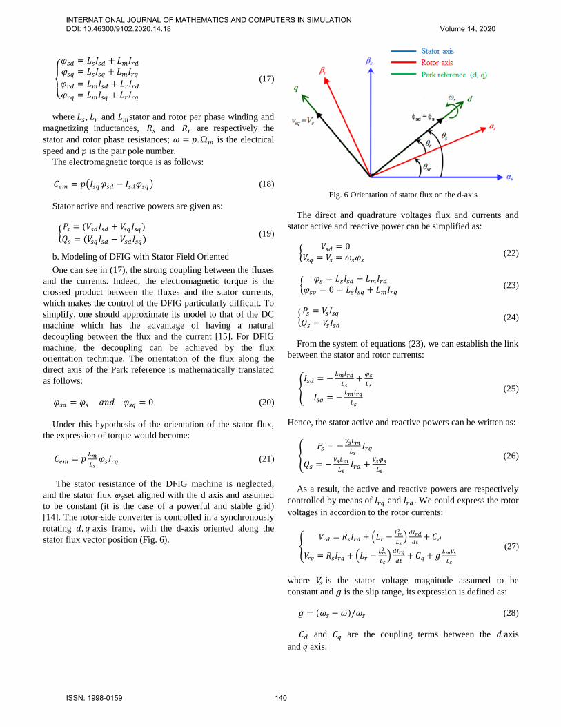
The stator resistance of the DFIG machine is neglected,
and the stator flux 𝜑𝑠set aligned with the d axis and assumed
to be constant (it is the case of a powerful and stable grid)
[14]. The rotor-side converter is controlled in a synchronously
rotating 𝑑, 𝑞 axis frame, with the d-axis oriented along the
stator flux vector position (Fig. 6).
Fig. 6 Orientation of stator flux on the d-axis
The direct and quadrature voltages flux and currents and
stator active and reactive power can be simplified as:
𝑉𝑠𝑑 = 0
𝑉𝑠𝑞 = 𝑉𝑠 = 𝜔𝑠𝜑𝑠 (22)
𝜑𝑠 = 𝐿𝑠𝐼𝑠𝑑 + 𝐿𝑚𝐼𝑟𝑑
𝜑𝑠𝑞 = 0 = 𝐿𝑠𝐼𝑠𝑞 + 𝐿𝑚𝐼𝑟𝑞 (23)
𝑃𝑠 = 𝑉𝑠𝐼𝑠𝑞𝑄𝑠 = 𝑉𝑠𝐼𝑠𝑑
(24)
From the system of equations (23), we can establish the link
between the stator and rotor currents:
𝐼𝑠𝑑 = −
𝐿𝑚𝐼𝑟𝑑
𝐿𝑠+
𝜑𝑠
𝐿𝑠
𝐼𝑠𝑞 = −𝐿𝑚𝐼𝑟𝑞
𝐿𝑠
(25)
Hence, the stator active and reactive powers can be written as:
𝑃𝑠 = −
𝑉𝑠𝐿𝑚
𝐿𝑠𝐼𝑟𝑞
𝑄𝑠 = −𝑉𝑠𝐿𝑚
𝐿𝑠𝐼𝑟𝑑 +
𝑉𝑠𝜑𝑠
𝐿𝑠
(26)
As a result, the active and reactive powers are respectively
controlled by means of 𝐼𝑟𝑞 and 𝐼𝑟𝑑. We could express the rotor
voltages in accordion to the rotor currents:
𝑉𝑟𝑑 = 𝑅𝑠𝐼𝑟𝑑 + (𝐿𝑟 −
𝐿𝑚2
𝐿𝑠)𝑑𝐼𝑟𝑑
𝑑𝑡+ 𝐶𝑑
𝑉𝑟𝑞 = 𝑅𝑠𝐼𝑟𝑞 + (𝐿𝑟 −𝐿𝑚2
𝐿𝑠)𝑑𝐼𝑟𝑞
𝑑𝑡+ 𝐶𝑞 + 𝑔
𝐿𝑚𝑉𝑠
𝐿𝑠
(27)
where 𝑉𝑠 is the stator voltage magnitude assumed to be
constant and 𝑔 is the slip range, its expression is defined as:
𝑔 = (𝜔𝑠 − 𝜔)/𝜔𝑠 (28)
𝐶𝑑 and 𝐶𝑞 are the coupling terms between the 𝑑 axis
and 𝑞 axis:
INTERNATIONAL JOURNAL OF MATHEMATICS AND COMPUTERS IN SIMULATION DOI: 10.46300/9102.2020.14.18 Volume 14, 2020
ISSN: 1998-0159 140
𝐶𝑑 = −𝑔𝜔𝑠 (𝐿𝑟 −
𝐿𝑚2
𝐿𝑠) 𝐼𝑟𝑞 = −𝑔𝜔𝑠𝜎𝐿𝑟𝐼𝑟𝑞
𝐶𝑞 = 𝑔𝜔𝑠 (𝐿𝑟 −𝐿𝑚2
𝐿𝑠) 𝐼𝑟𝑑 = 𝑔𝜔𝑠𝜎𝐿𝑟𝐼𝑟𝑑
(29)
where σ = 1 −Lm2
LsLr : the dispersion coefficient of the DFIG.
The electromotive forces respectively appear in the direct
and quadrature axes designated in 𝑓𝑒𝑚𝑑 and 𝑓𝑒𝑚𝑞.
𝑓𝑒𝑚𝑑 =
𝑉𝑠2
𝜔𝑠𝐿𝑠
𝑓𝑒𝑚𝑞 = 𝑔𝐿𝑚𝑉𝑠
𝐿𝑠
(30)
From (29) and (30), we can rewrite the rotor voltages as:
𝑉𝑟𝑑 = 𝑅𝑠𝐼𝑟𝑑 + 𝜎𝐿𝑟
𝑑𝐼𝑟𝑑
𝑑𝑡+ 𝐶𝑑
𝑉𝑟𝑞 = 𝑅𝑠𝐼𝑟𝑞 + 𝜎𝐿𝑟𝑑𝐼𝑟𝑞
𝑑𝑡+ 𝐶𝑞 + 𝑓𝑒𝑚𝑞
(31)
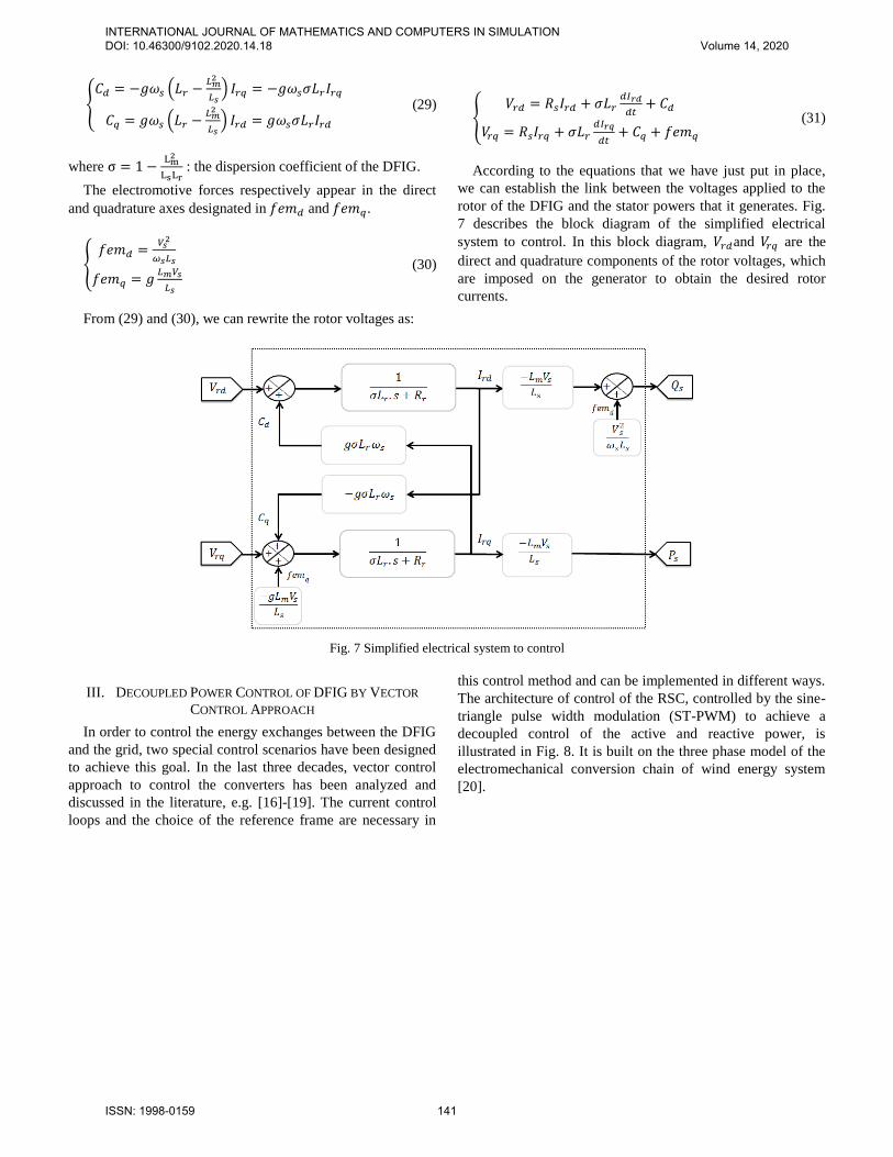
According to the equations that we have just put in place,
we can establish the link between the voltages applied to the
rotor of the DFIG and the stator powers that it generates. Fig.
7 describes the block diagram of the simplified electrical
system to control. In this block diagram, 𝑉𝑟𝑑and 𝑉𝑟𝑞 are the
direct and quadrature components of the rotor voltages, which
are imposed on the generator to obtain the desired rotor
currents.
Fig. 7 Simplified electrical system to control
III. DECOUPLED POWER CONTROL OF DFIG BY VECTOR
CONTROL APPROACH
In order to control the energy exchanges between the DFIG
and the grid, two special control scenarios have been designed
to achieve this goal. In the last three decades, vector control
approach to control the converters has been analyzed and
discussed in the literature, e.g. [16]-[19]. The current control
loops and the choice of the reference frame are necessary in
this control method and can be implemented in different ways.
The architecture of control of the RSC, controlled by the sine-
triangle pulse width modulation (ST-PWM) to achieve a
decoupled control of the active and reactive power, is
illustrated in Fig. 8. It is built on the three phase model of the
electromechanical conversion chain of wind energy system
[20].
INTERNATIONAL JOURNAL OF MATHEMATICS AND COMPUTERS IN SIMULATION DOI: 10.46300/9102.2020.14.18 Volume 14, 2020
ISSN: 1998-0159 141
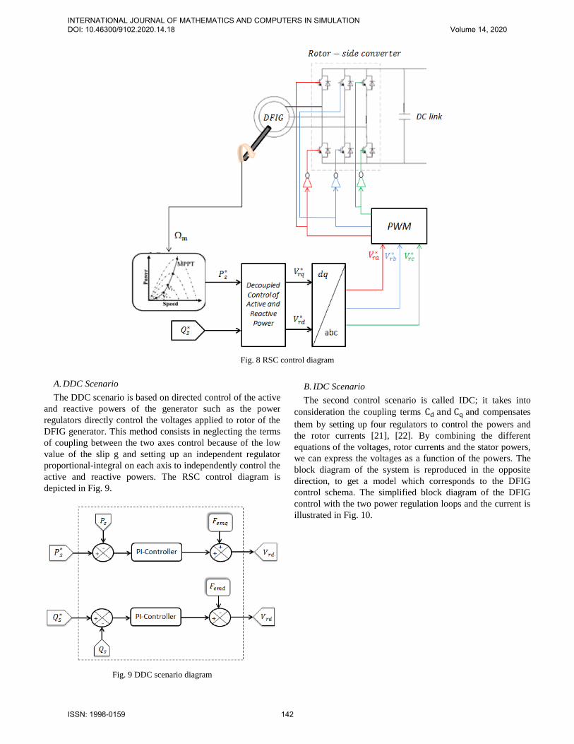
Fig. 8 RSC control diagram
A. DDC Scenario
The DDC scenario is based on directed control of the active
and reactive powers of the generator such as the power
regulators directly control the voltages applied to rotor of the
DFIG generator. This method consists in neglecting the terms
of coupling between the two axes control because of the low
value of the slip g and setting up an independent regulator
proportional-integral on each axis to independently control the
active and reactive powers. The RSC control diagram is
depicted in Fig. 9.
Fig. 9 DDC scenario diagram
B. IDC Scenario
The second control scenario is called IDC; it takes into
consideration the coupling terms Cd and Cq and compensates
them by setting up four regulators to control the powers and
the rotor currents [21], [22]. By combining the different
equations of the voltages, rotor currents and the stator powers,
we can express the voltages as a function of the powers. The
block diagram of the system is reproduced in the opposite
direction, to get a model which corresponds to the DFIG
control schema. The simplified block diagram of the DFIG
control with the two power regulation loops and the current is
illustrated in Fig. 10.
INTERNATIONAL JOURNAL OF MATHEMATICS AND COMPUTERS IN SIMULATION DOI: 10.46300/9102.2020.14.18 Volume 14, 2020
ISSN: 1998-0159 142
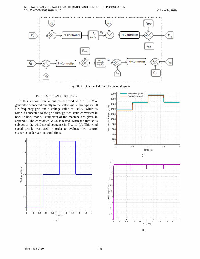
Fig. 10 Direct decoupled control scenario diagram
IV. RESULTS AND DISCUSSION
In this section, simulations are realized with a 1.5 MW
generator connected directly to the stator with a three-phase 50
Hz frequency grid and a voltage value of 398 V; while its
rotor is connected to the grid through two static converters in back-to-back mode. Parameters of the machine are given in
appendix. The considered WGS is tested, when the turbine is
subject to the wind speed sequence in Fig. 11 (a). This wind
speed profile was used in order to evaluate two control
scenarios under various conditions.
(a)
(b)
(c)
INTERNATIONAL JOURNAL OF MATHEMATICS AND COMPUTERS IN SIMULATION DOI: 10.46300/9102.2020.14.18 Volume 14, 2020
ISSN: 1998-0159 143
(d)
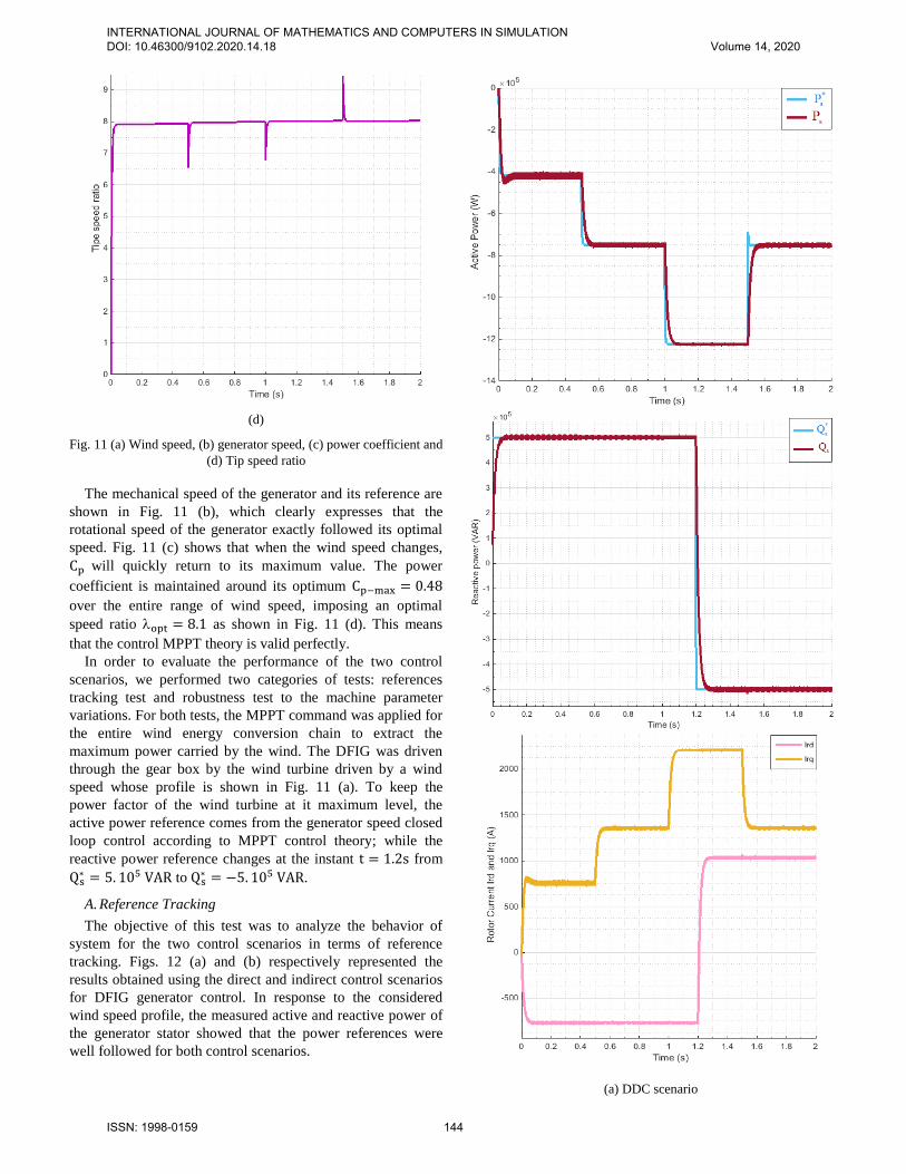
Fig. 11 (a) Wind speed, (b) generator speed, (c) power coefficient and
(d) Tip speed ratio
The mechanical speed of the generator and its reference are
shown in Fig. 11 (b), which clearly expresses that the
rotational speed of the generator exactly followed its optimal
speed. Fig. 11 (c) shows that when the wind speed changes,
Cp will quickly return to its maximum value. The power
coefficient is maintained around its optimum Cp−max = 0.48
over the entire range of wind speed, imposing an optimal
speed ratio opt = 8.1 as shown in Fig. 11 (d). This means
that the control MPPT theory is valid perfectly.
In order to evaluate the performance of the two control
scenarios, we performed two categories of tests: references
tracking test and robustness test to the machine parameter
variations. For both tests, the MPPT command was applied for
the entire wind energy conversion chain to extract the
maximum power carried by the wind. The DFIG was driven
through the gear box by the wind turbine driven by a wind
speed whose profile is shown in Fig. 11 (a). To keep the
power factor of the wind turbine at it maximum level, the
active power reference comes from the generator speed closed
loop control according to MPPT control theory; while the
reactive power reference changes at the instant t = 1.2s from
Qs∗ = 5. 105 VAR to Qs
∗ = −5. 105 VAR.
A. Reference Tracking
The objective of this test was to analyze the behavior of
system for the two control scenarios in terms of reference
tracking. Figs. 12 (a) and (b) respectively represented the
results obtained using the direct and indirect control scenarios
for DFIG generator control. In response to the considered
wind speed profile, the measured active and reactive power of
the generator stator showed that the power references were
well followed for both control scenarios.
(a) DDC scenario
INTERNATIONAL JOURNAL OF MATHEMATICS AND COMPUTERS IN SIMULATION DOI: 10.46300/9102.2020.14.18 Volume 14, 2020
ISSN: 1998-0159 144
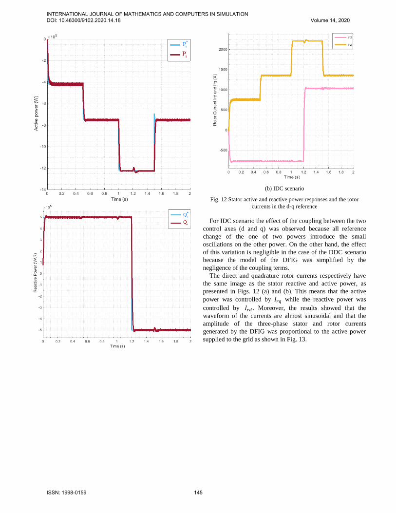
(b) IDC scenario
Fig. 12 Stator active and reactive power responses and the rotor
currents in the d-q reference
For IDC scenario the effect of the coupling between the two
control axes (d and q) was observed because all reference
change of the one of two powers introduce the small
oscillations on the other power. On the other hand, the effect
of this variation is negligible in the case of the DDC scenario
because the model of the DFIG was simplified by the
negligence of the coupling terms.
The direct and quadrature rotor currents respectively have
the same image as the stator reactive and active power, as
presented in Figs. 12 (a) and (b). This means that the active
power was controlled by 𝐼𝑟𝑞 while the reactive power was
controlled by 𝐼𝑟𝑑 . Moreover, the results showed that the
waveform of the currents are almost sinusoidal and that the
amplitude of the three-phase stator and rotor currents
generated by the DFIG was proportional to the active power
supplied to the grid as shown in Fig. 13.
INTERNATIONAL JOURNAL OF MATHEMATICS AND COMPUTERS IN SIMULATION DOI: 10.46300/9102.2020.14.18 Volume 14, 2020
ISSN: 1998-0159 145
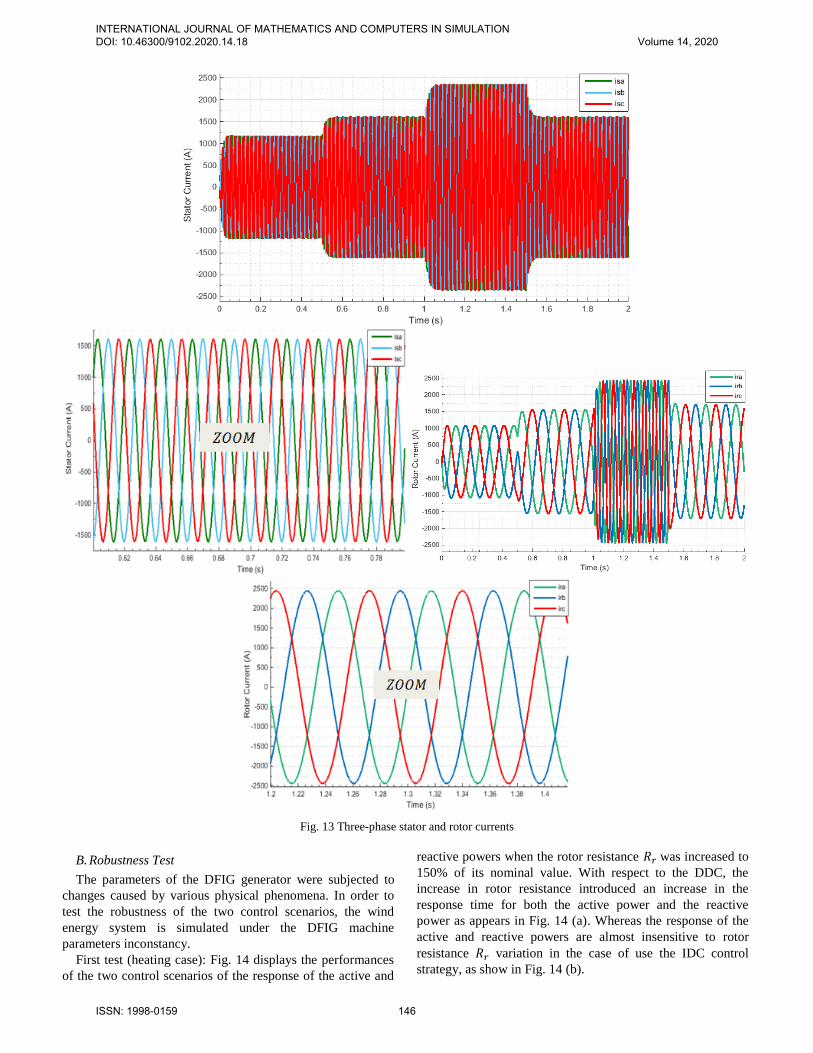
Fig. 13 Three-phase stator and rotor currents
B. Robustness Test
The parameters of the DFIG generator were subjected to
changes caused by various physical phenomena. In order to
test the robustness of the two control scenarios, the wind
energy system is simulated under the DFIG machine
parameters inconstancy.
First test (heating case): Fig. 14 displays the performances
of the two control scenarios of the response of the active and
reactive powers when the rotor resistance 𝑅𝑟 was increased to
150% of its nominal value. With respect to the DDC, the
increase in rotor resistance introduced an increase in the
response time for both the active power and the reactive
power as appears in Fig. 14 (a). Whereas the response of the
active and reactive powers are almost insensitive to rotor
resistance 𝑅𝑟 variation in the case of use the IDC control
strategy, as show in Fig. 14 (b).
INTERNATIONAL JOURNAL OF MATHEMATICS AND COMPUTERS IN SIMULATION DOI: 10.46300/9102.2020.14.18 Volume 14, 2020
ISSN: 1998-0159 146
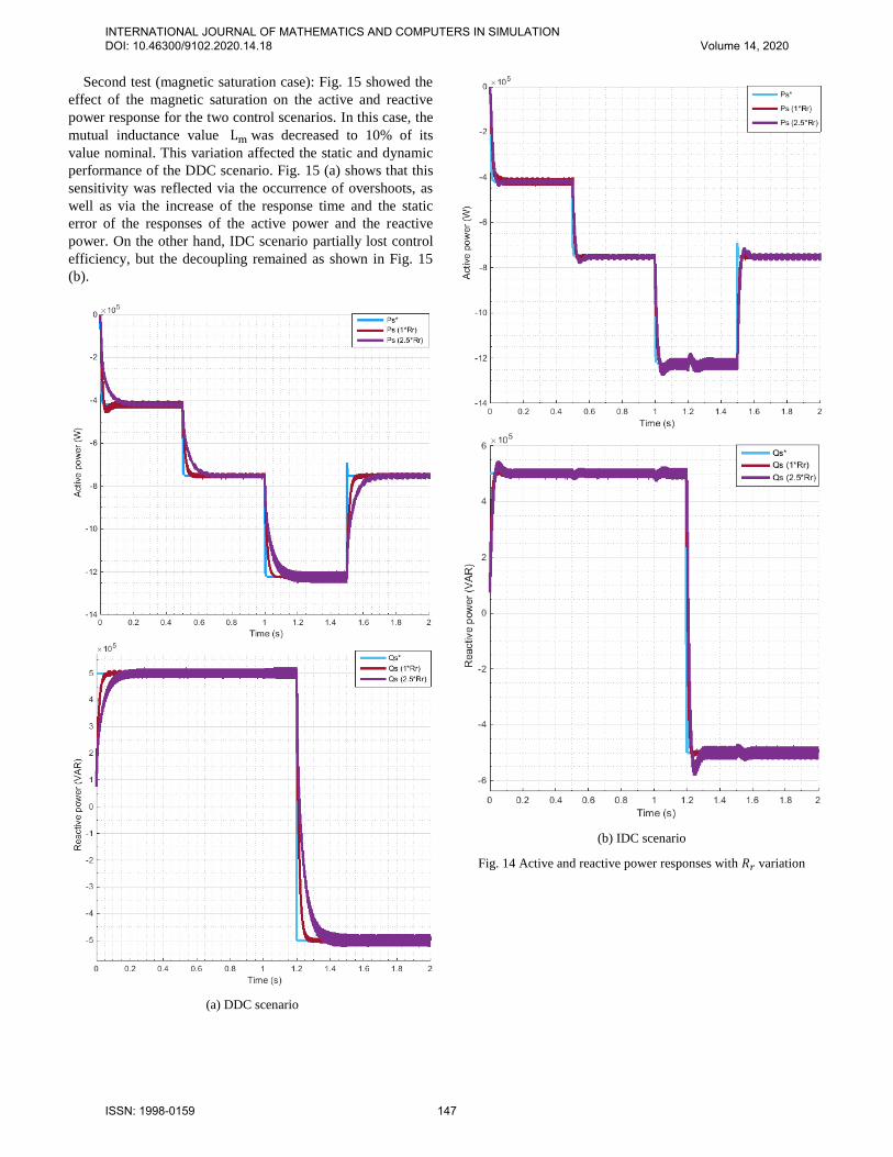
Second test (magnetic saturation case): Fig. 15 showed the
effect of the magnetic saturation on the active and reactive
power response for the two control scenarios. In this case, the
mutual inductance value Lm was decreased to 10% of its
value nominal. This variation affected the static and dynamic
performance of the DDC scenario. Fig. 15 (a) shows that this
sensitivity was reflected via the occurrence of overshoots, as
well as via the increase of the response time and the static
error of the responses of the active power and the reactive
power. On the other hand, IDC scenario partially lost control
efficiency, but the decoupling remained as shown in Fig. 15
(b).
(a) DDC scenario
(b) IDC scenario
Fig. 14 Active and reactive power responses with 𝑅𝑟 variation
INTERNATIONAL JOURNAL OF MATHEMATICS AND COMPUTERS IN SIMULATION DOI: 10.46300/9102.2020.14.18 Volume 14, 2020
ISSN: 1998-0159 147
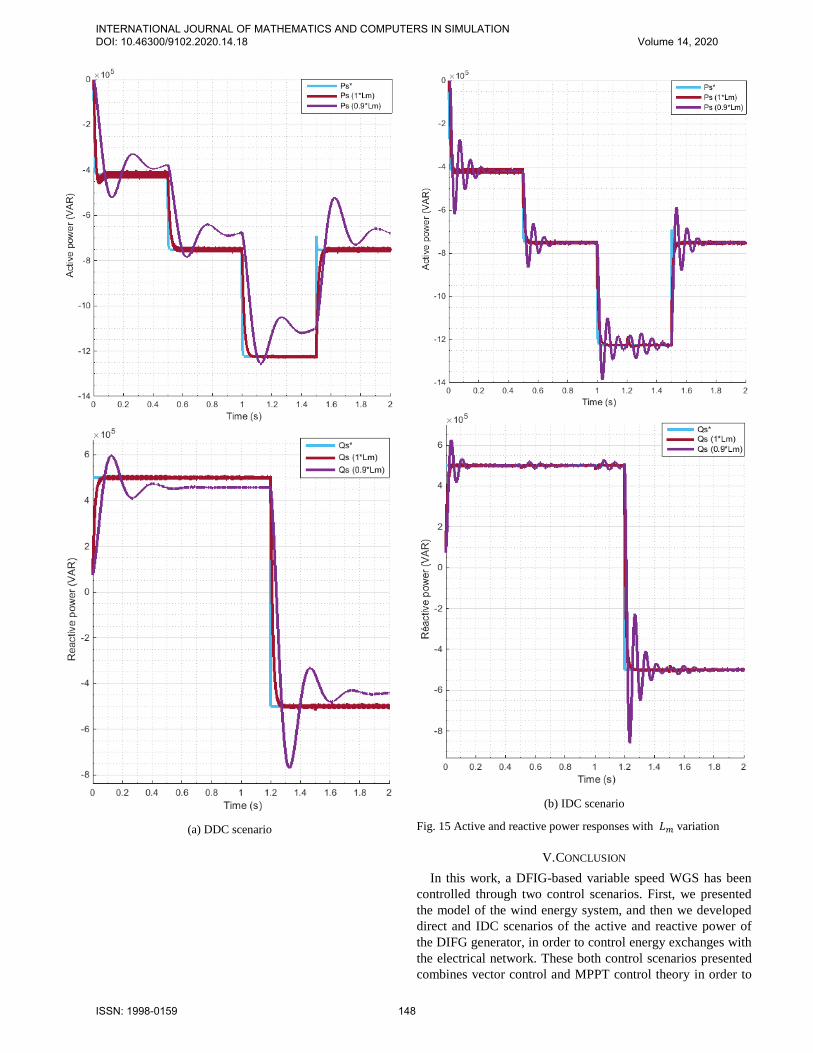
(a) DDC scenario
(b) IDC scenario
Fig. 15 Active and reactive power responses with 𝐿𝑚 variation
V. CONCLUSION
In this work, a DFIG-based variable speed WGS has been
controlled through two control scenarios. First, we presented
the model of the wind energy system, and then we developed
direct and IDC scenarios of the active and reactive power of
the DIFG generator, in order to control energy exchanges with
the electrical network. These both control scenarios presented
combines vector control and MPPT control theory in order to
INTERNATIONAL JOURNAL OF MATHEMATICS AND COMPUTERS IN SIMULATION DOI: 10.46300/9102.2020.14.18 Volume 14, 2020
ISSN: 1998-0159 148
maximize the generated power from WGS. So as to examine
the performances of each control scenario, the system
performance was tested and compared by simulation in terms
of reference tracking and robustness against the parametric
variations of the DFIG. The results obtained showed that the
two methods ensured perfect decoupling the powers generated
by the DFIG when the powers references change
instantaneously. They show also that DDC is the simplest
implementation, but not the best efficient. However, the IDC
scenario allows us, with the loop cascade, to have a most
robust and efficient system. It is assuredly extremely complex
implementation compared to DDC scenario, but it has an
optimal operation of electrical generation system by reducing
probable problems related to parametric variations of the
DFIG and the wind system. Thus, the continuation of the work
can be designed and have a real implementation of this control
scenario in an FPGA.
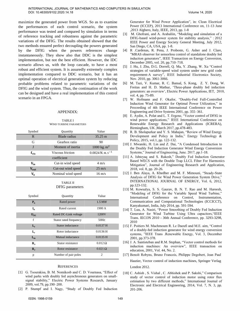
APPENDIX:
TABLE I
WIND TURBINE PARAMETERS
Symbol Quantity Value
R Blade radius 35.25 m
G Gearbox ratio 90
J Moment of inertia 1000 kg.m2
𝐟𝐯𝐢𝐬 Viscous friction 0.0024 N.M. S−1
coefficient
𝐕𝐢𝐧 Cut-in wind speed 4 m/s
𝐕𝐨𝐮𝐭 Cut-out wind speed 25 m/s
𝐕𝐧 Nominal wind speed 16 m/s
TABLE II
DFIG parameters
Symbol Quantity Value
𝐏𝐧 Rated power 1.5 MW
𝐈𝐧 Rated current 1900 A
𝐔𝐃𝐂 Rated DC-Link voltage 1200V
f Stator rated frequency 50HZ
𝐋𝐬 Stator inductance 0.0137 H
𝐋𝐫 Rotor inductance 0.0136 H
𝐋𝐦 Mutual inductance 0.0135 H
𝐑𝐬 Stator resistance 0.012 Ω
𝐑𝐫 Rotor resistance 0.021 Ω
p Number of pair poles 2
REFERENCES
[1] G. Tsourakisa, B. M. Nomikosb and C. D. Vournasa, “Effect of
wind parks with doubly fed asynchronous generators on small-
signal stability,” Electric Power Systems Research, January
2009, vol.79, pp.190–200.
[2] P. Stumpf and I. Nagy, “Study of Doubly Fed Induction
Generator for Wind Power Application”, in: Clean Electrical
Power (ICCEP), 2013 International Conference on, 11-13 June
,2013 Alghero, Italy, IEEE, 2013, pp. 1-8
[3] M. Ghofrani, and A. Arabaliin, “Modeling and simulation of a
DFIG-based wind-power system for stability analysis,” : 2012
IEEE Power and Energy Society General Meeting, July 2012,
San Diego, CA, USA, pp. 1-8.
[4] R .Cardenas, R. Pena, J. Proboste, G. Asher and J. Clare,
”MRAS observer for sensorless control of standalone doubly fed
induction generators”, IEEE Transaction on Energy Conversion,
December 2005, vol. 20, pp.710–718.
[5] J. Hu, J. Zhu, D.G. Dorrell, Q. Ma, Y. Zhang, W. Xu “Control
strategies of variable-speed wind system under new grid code
requirement-A survey”, IEEE Industrial Electronics Society,
Nov. 2010, pp. 3061-3066.
[6] M. Tazi, V. Kumar, R. C. Bansal, S. Kong, Z. Y. Dong, W.
Freitas and H. D. Mathur, ‘Three-phase doubly fed induction
generators: an overview’, Electric Power Applications, IET, 2010,
vol. 4, pp. 75-89.
[7] W. Hofmann and F. Okafor, “Doubly-Fed Full-Controlled
Induction Wind Generator for Optimal Power Utilization,” in
Proceeding of 4th IEEE International Conference on Power
Engineering and Drive Systems 2001, pp. 355–361.
[8] E. Aydin, A. Polat and L. T. Ergene, “Vector control of DFIG in
wind power applications,” IEEE International Conference on
Renewable Energy Research and Applications (ICRERA),
Birmingham, UK ,March 2017, pp.478-483.
[9] R. B. Sholapurkar and Y. S. Mahajan, “Review of Wind Energy
Development and Policy in India,” Energy Technology &
Policy, 2015, vol.1, pp. 122-132.
[10] J. Mwaniki, H. Lin and Z. Dai, “A Condensed Introduction to
the Doubly Fed Induction Generator Wind Energy Conversion
Systems,” Journal of Engineering, June. 2017, pp.1-18.
[11] A. Ishteyaq and S. Rakesh,” Doubly Fed Induction Generator
Based WECS with the Double Trap LLCL Filter For Harmonics
Mitigation”, Journal of Engineering Research and Application,
2018, vol. 8, pp. 20-26.
[12] J. Ben Alaya, A. Khedher and M. F. Mimouni, “Steady-State
Analysis of DFIG for Wind Power Generation System Drive,”
INTERNATIONAL JOURNAL OF ENERGY, Vol. 6, 2012,
pp.123-132.
[13] M. Kowsalya, S. S. Gaurav, B. N. T. Rao and M. Hareesh,
“Modeling of DFIG for the Variable Speed Wind Turbine,”
International Conference on Control, Instrumentation,
Communication and Computational Technologies (ICCICCT),
Kanyakumari, India, July 2014, pp. 591-594.
[14] T. Luu, A. Nasiri, “Power Smoothing of Doubly Fed Induction
Generator for Wind Turbine Using Ultra capacitors,“IEEE
Trans. IECON 2010 - 36th Annual Conference, pp. 3293-3298,
2010
[15] F. Poitiers M. Machmoum R. Le Daeufi and M.E. aim, “Control
of a doubly-fed induction generator for wind energy conversion
systems, ”IEEE Trans .Renewable Energy, Vol. 3, December
2001, pp.373-378.
[16] J. A. Santisteban and R.M. Stephan, “Vector control methods for
induction machines: An overview”, IEEE transaction on
education, 2001, Vol. 44, No. 2.
[17] Benoît Robyns, Bruno Francois, Philippe Degobert, Jean Paul
Hautier, Vector control of induction machines, Springer Verlag
London 2012.
[18] C. Ashish , S. Vishal , C. Abhishek and P. Sakshi,” Comparison
study of vector control of induction motor using rotor flux
estimation by two different methods,” International Journal of
Electronic and Electrical Engineering, 2014, Vol. 7, N. 3, pp.
201-206.
INTERNATIONAL JOURNAL OF MATHEMATICS AND COMPUTERS IN SIMULATION DOI: 10.46300/9102.2020.14.18 Volume 14, 2020
ISSN: 1998-0159 149

[19] A. S. M. Tausif, A. R. Umale, R. K. Kirpane, ”Vector control
methods for variable speed AC motors,” International Research
Journal of Engineering and Technology, 2017, Vol. 4, pp. 340-
343.
[20] N. Ramesh Babu and P. Arulmozhivarman, “Wind energy
conversion systems-A technical review”, Journal of Engineering
Science and Technology, 2013, pp. 493 - 507.
[21] M. Boutoubat, L. Mokrani, M. Machmoum. Control of a wind
energy conversion system equipped by a DFIG for active power
generation and power quality improvement. Renewable Energy
50 (2013), pp. 378-386.
[22] SY. Shao, E. Abdi, F. Barati, R. McMahon. Stator-flux-oriented
vector for brushless doubly fed induction generator. IEEE
Transactions on Industrial Electronics, 2009, 56(10): 4220–
4228.
Creative Commons Attribution License 4.0 (Attribution 4.0 International, CC BY 4.0)
This article is published under the terms of the Creative Commons Attribution License 4.0 https://creativecommons.org/licenses/by/4.0/deed.en_US
INTERNATIONAL JOURNAL OF MATHEMATICS AND COMPUTERS IN SIMULATION DOI: 10.46300/9102.2020.14.18 Volume 14, 2020
ISSN: 1998-0159 150