Embed Size (px)
Citation preview
27th International Conference on Technology in Collegiate Mathematics
247www.ictcm.com
MATHEMATICS: THE POWER BEHIND THE DRONE
Frank Wattenberg1
Matthew MogensenDepartment of Mathematical Sciences
United States Military AcademyWest Point, NY 10996
[email protected]@usma.edu
The photograph above was taken by an aerial drone controlled by a microprocessorvery much like the Arduino. Although you immediately see a drone’s motors androtors, the underlying mathematics – the algorithms and programs that power thedrone – are not visible. Without this mathematics a drone would never fly. Thispaper talks about the underlying mathematics and programming that give Arduinosand drones life. We give several examples showing how these ideas can enliven ourcurrent mathematics classes.
1The views expressed in this article are those of the authors and do not reflect the official policyor position of the U.S. Military Academy, the Department of the Army, the Department of Defense,or the U.S. Government.
27th International Conference on Technology in Collegiate Mathematics
248www.ictcm.com
Figure 1: The Arduino starter kit
Figure 1 shows the Arduino Starter kit. This kit is available for under $100.00 andhas all the parts and documentation needed to begin the study of computer-controlleddevices. For algebra and pre-calculus courses this box is essentially a box of functionsand provides an engaging playground in which we can learn about functions. Thisis a good place to begin a discussion about using robotic devices in mathematicsclasses.
The f Machinex → → f(x)
Figure 2: A function – a machine that accepts input and produces output
Project 1: A Simple Function
Figure 2 is a typical figure from a typical mathematics textbook discussion of func-tions. We often introduce key ideas like domain and co-domain by looking atalgebraically defined functions like:
27th International Conference on Technology in Collegiate Mathematics
249www.ictcm.com
f(x) =√1− x
and noting that this function is undefined when x < 1 since you can’t take the squareroot of a negative number. Thus, the domain of this function is the set x : 1 ≤ x,or the interval [1,+∞) – BORING!!!
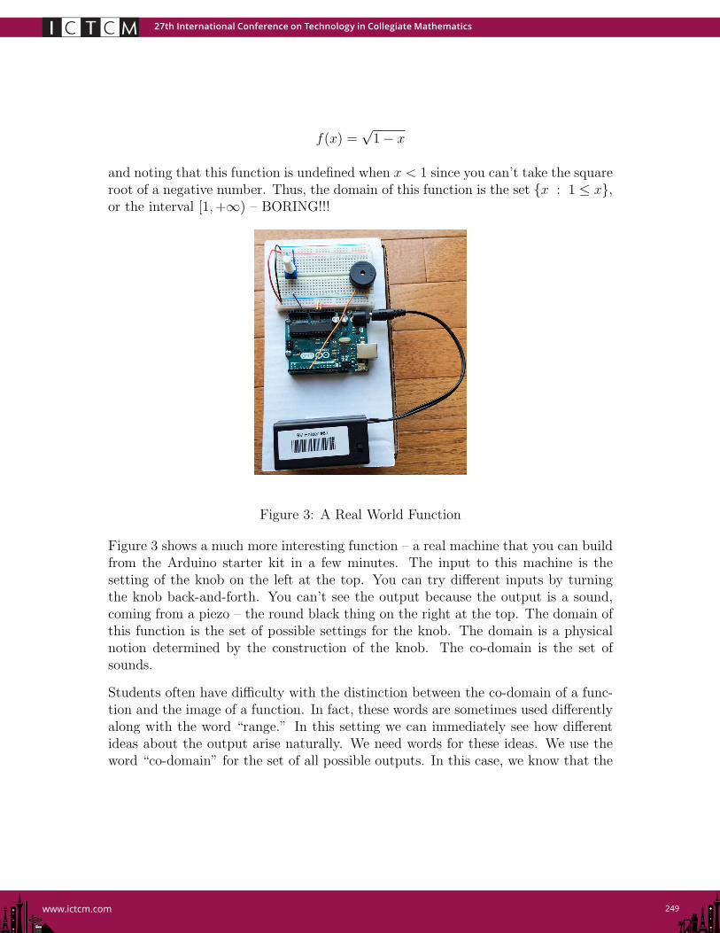
Figure 3: A Real World Function
Figure 3 shows a much more interesting function – a real machine that you can buildfrom the Arduino starter kit in a few minutes. The input to this machine is thesetting of the knob on the left at the top. You can try different inputs by turningthe knob back-and-forth. You can’t see the output because the output is a sound,coming from a piezo – the round black thing on the right at the top. The domain ofthis function is the set of possible settings for the knob. The domain is a physicalnotion determined by the construction of the knob. The co-domain is the set ofsounds.
Students often have difficulty with the distinction between the co-domain of a func-tion and the image of a function. In fact, these words are sometimes used differentlyalong with the word “range.” In this setting we can immediately see how differentideas about the output arise naturally. We need words for these ideas. We use theword “co-domain” for the set of all possible outputs. In this case, we know that the
27th International Conference on Technology in Collegiate Mathematics
250www.ictcm.com
outputs are sounds. But, this particular machine with this particular domain doesn’tproduce all possible sounds. You can determine which sounds it actually produces bytrying all possible inputs. Turn the knob back-and-forth several times slowly. Theset of outputs actually produced from all possible inputs is called the image.
This is also a good setting in which to discuss the other attributes of functions.For example, a function is repeatable – the same input always produces the sameoutput. Students studying functions like f(x) = 2x + 3 may not appreciate themeaning or importance of this attribute but in this real world context it is much moremeaningful. In fact, we can stress that this is an ideal property of mathematicallydefined functions that may be hard to achieve in the real world – for example, dothe sounds change as the batteries are depleted?
The listing at the bottom of this page shows the entire program for this machine.Like all Arduino programs it includes two functions:
• A function setup() – This function is executed once to initialize the device.In this case it sets one of the Arduino pins, digital pin 6, up as an output pin.It will be used to control the piezo.
• A function loop() – This function is executed repeatedly while the device ison. It reads the setting of the knob, which is wired to analog pin A0, and sendsa signal to the piezo through digital pin 6.
void setup()
pinMode(6, OUTPUT);
void loop()
int frequency = 440 + analogRead(A0)/2;
tone(6, frequency);
27th International Conference on Technology in Collegiate Mathematics
251www.ictcm.com
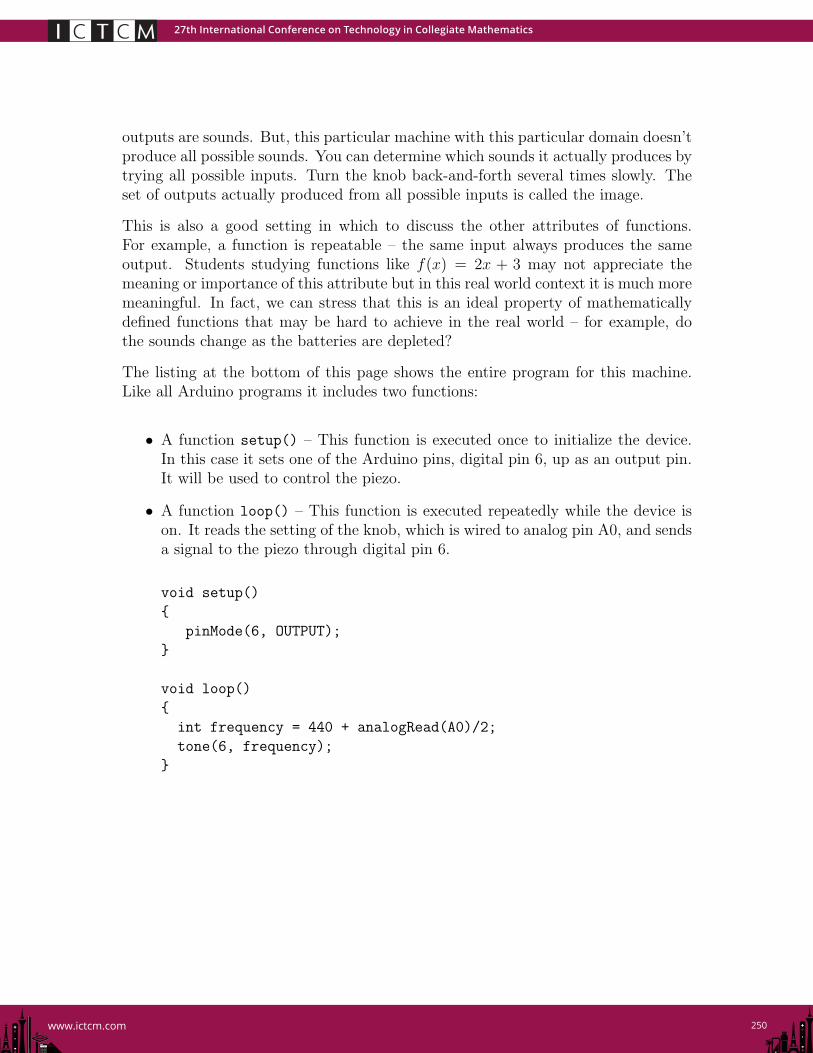
Figure 4: The Arduino Uno
The programs that control an Arduino are called sketches. Every sketch has at leastthese two functions – setup() and loop(). Figure 4 shows the Arduino Uno boardthat we use. It has a number of different “ports,” sometimes called “pins.” Notice inFigure 3 that wires connect some of these ports to components on the breadboard.Wiring the device goes hand-in-hand with programming.
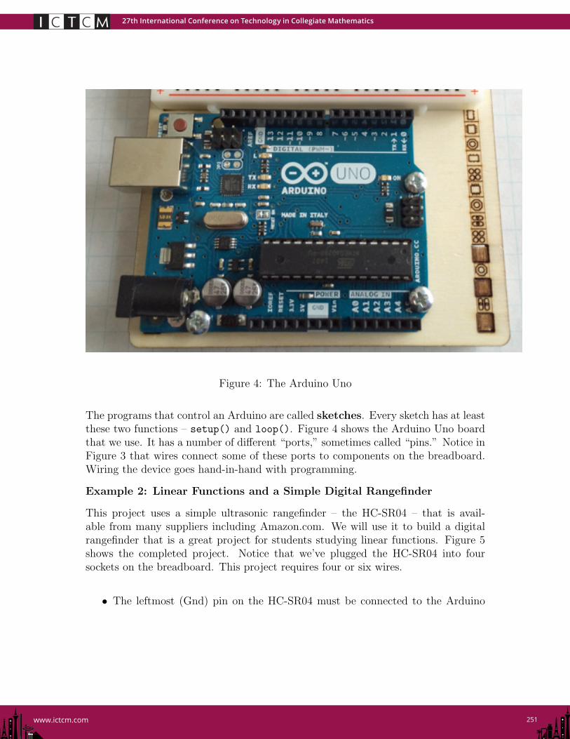
Example 2: Linear Functions and a Simple Digital Rangefinder
This project uses a simple ultrasonic rangefinder – the HC-SR04 – that is avail-able from many suppliers including Amazon.com. We will use it to build a digitalrangefinder that is a great project for students studying linear functions. Figure 5shows the completed project. Notice that we’ve plugged the HC-SR04 into foursockets on the breadboard. This project requires four or six wires.
• The leftmost (Gnd) pin on the HC-SR04 must be connected to the Arduino
27th International Conference on Technology in Collegiate Mathematics
252www.ictcm.com
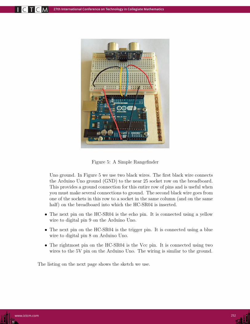
Figure 5: A Simple Rangefinder
Uno ground. In Figure 5 we use two black wires. The first black wire connectsthe Arduino Uno ground (GND) to the near 25 socket row on the breadboard.This provides a ground connection for this entire row of pins and is useful whenyou must make several connections to ground. The second black wire goes fromone of the sockets in this row to a socket in the same column (and on the samehalf) on the breadboard into which the HC-SR04 is inserted.
• The next pin on the HC-SR04 is the echo pin. It is connected using a yellowwire to digital pin 9 on the Arduino Uno.
• The next pin on the HC-SR04 is the trigger pin. It is connected using a bluewire to digital pin 8 on Arduino Uno.
• The rightmost pin on the HC-SR04 is the Vcc pin. It is connected using twowires to the 5V pin on the Arduino Uno. The wiring is similar to the ground.
The listing on the next page shows the sketch we use.
27th International Conference on Technology in Collegiate Mathematics
253www.ictcm.com
#define trigger 8 // The rangefinder trigger pin is conected to D8
#define echo 9 // The rangefinder echo pin is connected to D9
void setup()
pinMode(trigger, OUTPUT); // The Uno sends signals to the rangefinder trigger pin
pinMode(echo, INPUT); // and receives signals from the rangefinder echo pin
Serial.begin(9600); // The Uno sends information to the computer
digitalWrite(trigger, LOW); // Set the trigger signal to low.
void loop()
digitalWrite(trigger, HIGH); // The Uno sends the rangefinder a pulse whose duration
delayMicroseconds(10); // is 10 microseconds. This causes to rangefinder to
digitalWrite(trigger, LOW); // emit a sonar pulse
Serial.print("Time to pulse return: "); // Print time for the pulse
Serial.println(pulseIn(echo, HIGH)); // to return from obstacle.
delay(1000); // Wait one second before next measurement.
The comments describe how the sketch works. It is designed to return the timerequired from when the unit is triggered until a sonar pulse returns after beingreflected by an object. This is a great project for introducing or exercising linearfunctions. The time required should be given by a linear function, y = mx + b. Besure to ask your students to interpret the values of the parameters m and b. Theycan use their answers to print distance measurements in units of their choice.
Example 3: A Simple Digital Level
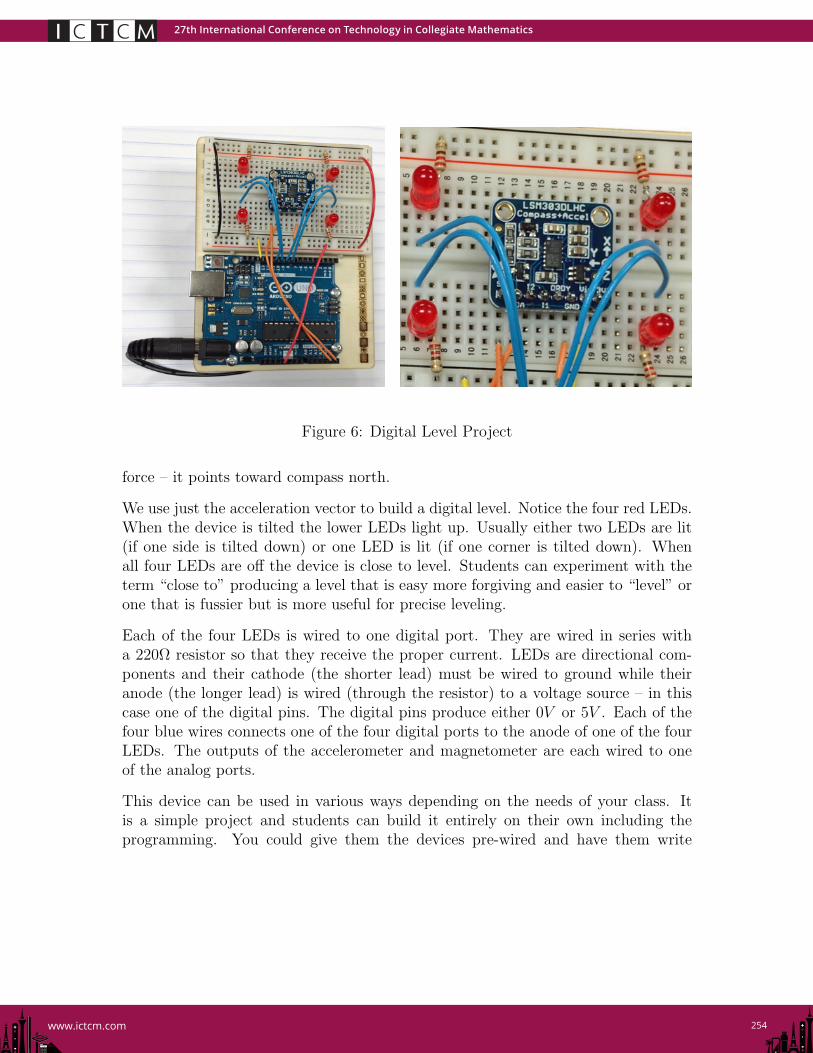
Figure 6 shows our last example – a good example to use when students are studyingvectors. It uses another board that is not included in the Arduino starter kit butis very useful and available for under $15.00 from Adafruit and other sources. Thisboard includes both a magnetometer for measuring the ambient magnetic field and anaccelerometer that is often used to measure the ambient gravitational field. Mobiledevices, like cell phones and tablets use these capabilities together with GPS todetermine both where they are located (GPS) and how they are being held – thatis, the direction in which they are facing (magnetometer) and how they are tilted(accelerometer). When the device is still, the output of the accelerometer is the vectorpointing toward the Earth’s center of mass and whose magnitude is the accelerationdue to gravity. When the device is accelerating, the output is the total accelerationvector. The output of the magnetometer is the vector giving the ambient magnetic
27th International Conference on Technology in Collegiate Mathematics
254www.ictcm.com
Figure 6: Digital Level Project
force – it points toward compass north.
We use just the acceleration vector to build a digital level. Notice the four red LEDs.When the device is tilted the lower LEDs light up. Usually either two LEDs are lit(if one side is tilted down) or one LED is lit (if one corner is tilted down). Whenall four LEDs are off the device is close to level. Students can experiment with theterm “close to” producing a level that is easy more forgiving and easier to “level” orone that is fussier but is more useful for precise leveling.
Each of the four LEDs is wired to one digital port. They are wired in series witha 220Ω resistor so that they receive the proper current. LEDs are directional com-ponents and their cathode (the shorter lead) must be wired to ground while theiranode (the longer lead) is wired (through the resistor) to a voltage source – in thiscase one of the digital pins. The digital pins produce either 0V or 5V . Each of thefour blue wires connects one of the four digital ports to the anode of one of the fourLEDs. The outputs of the accelerometer and magnetometer are each wired to oneof the analog ports.
This device can be used in various ways depending on the needs of your class. Itis a simple project and students can build it entirely on their own including theprogramming. You could give them the devices pre-wired and have them write
27th International Conference on Technology in Collegiate Mathematics
255www.ictcm.com
the program. They basically have to decide which LEDs to turn on based on theacceleration vector and what tolerance to use. You might also give them everythingexcept the tolerance and have them experiment with different values. The listingbelow shows the program we use.
#include <Wire.h>
#include <Adafruit_Sensor.h>
#include <Adafruit_LSM303_U.h>
#include <Math.h>
Adafruit_LSM303_Mag_Unified mag = Adafruit_LSM303_Mag_Unified(12345);
Adafruit_LSM303_Accel_Unified accel = Adafruit_LSM303_Accel_Unified(54321);
int rightBack = 10;
int rightFront = 11;
int leftBack = 9;
int leftFront = 8;
float epsilon = 0.15;
void setup()
Serial.begin(9600);
pinMode(rightBack, OUTPUT);
pinMode(leftBack, OUTPUT);
pinMode(rightFront, OUTPUT);
pinMode(leftFront, OUTPUT);
if(!accel.begin())
Serial.println("Error initializing accelerometer");
while(1);
void loop()
float ax, ay, az;
sensors_event_t accelEvent;
accel.getEvent(&accelEvent);
ax = accelEvent.acceleration.x;
ay = accelEvent.acceleration.y;
az = accelEvent.acceleration.z;
Serial.print("ax, ay, az = ");
Serial.print(ax);
Serial.print(", ");
27th International Conference on Technology in Collegiate Mathematics
256www.ictcm.com
Serial.print(ay);
Serial.print(", ");
Serial.println(az);
digitalWrite(rightBack, LOW);
digitalWrite(rightFront, LOW);
digitalWrite(leftBack, LOW);
digitalWrite(leftFront, LOW);
if ((ax > epsilon) && (ay > epsilon)) digitalWrite(leftFront, HIGH);
if ((ax > epsilon) && (ay < -epsilon)) digitalWrite(rightFront, HIGH);
if ((ax < -epsilon) && (ay > epsilon)) digitalWrite(leftBack, HIGH);
if ((ax < -epsilon) && (ay < -epsilon)) digitalWrite(rightBack, HIGH);
if ((ax > epsilon) && (abs(ay) < epsilon))
digitalWrite(leftFront, HIGH);
digitalWrite(rightFront, HIGH);
if ((ax < -epsilon) && (abs(ay) < epsilon))
digitalWrite(leftBack, HIGH);
digitalWrite(rightBack, HIGH);
if ((ay > epsilon) && (abs(ax) <= epsilon))
digitalWrite(leftFront, HIGH);
digitalWrite(leftBack, HIGH);
if ((ay < -epsilon) && (abs(ax) <= epsilon))
digitalWrite(rightFront, HIGH);
digitalWrite(rightBack, HIGH);
delay(100);