Embed Size (px)
Citation preview
18
International Journal of Emerging Trends in Electrical and Electronics (IJETEE – ISSN: 2320-9569) Vol. 12, Issue. 2, Feb-2016
Mathematical Modeling of Wind Energy SystemUsing Two Mass Model Including Generator
LossesPatil Ashwini, Dr. Thosar Archana
Abstract: Evolution of new technology has increased the powerdemand. Because of such high demands and limited energyresources it is essential to optimize the energy production andcost. The energy companies are leading strong researches of thewind energy systems for energy security purpose.Large capacity wind energy systems are installed offshorewhere non planned service is very costly. The fault tolerantcontrol systems are beneficial when faults are detected duringnext planned service. It secures the energy production even iffault occurs. For designing any control system an appropriatemathematical model is always needed. The literature revealsone mass, two mass, three mass and six mass mathematicalmodels of wind energy system. An attempt is made to develop amodified two mass mathematical model to design a faulttolerant control system. In wind energy systems the mechanicalfaults like misalignments in the drive train, gears and bearingsfaults are very frequent. These are subject to a wear processand cause frictional losses. This paper addresses these faults inthe mathematics of the wind energy system. Further the work isextended to study the variations of the parameters generatorinertia constant, spring constant, viscous friction coefficient andgear ratio on the pole-zero plot and is related with the physicaldesign of the wind turbine. Behaviour of the wind turbineduring drive train faults are simulated and briefly discussed.
Keywords: Mathematical model of wind energy system;pole-zero plot; stability analysis; shaft stiffness; viscous frictioncoefficient; gear ratio; generator inertia
I. INTRODUCTION
The conventional energy sources use fossil fuels. It hasadverse effect of polluting environment. The problem ofglobal warming and reduction of fossil fuel resources hasforced to look for the alternative energy resources. Theincreased government support has caused the flourished windpower installation globally. Therefore, the control engineershave challenge to develop the techniques for reducing theoperational cost and increasing the reliability. In last decadesthe wind energy systems have been a subject of an intenseresearch programme.The focus is on large capacity windenergy systems. The large capacity wind energy systems areremotely located. The frequent fluctuations and large changein intensity of wind causes output power fluctuations. It alsocauses various faults in the whole structure, which may resultthe major failure of the system. To study the impact of thesefaults and design an advance fault tolerant control systemsthe wind energy system must be effectively mathematicallymodeled. Also its stability study must be done intensely.
In recent papers the research has been done on themodeling and simulation of the wind energy system. The
detailed description of nonlinear wind turbine simulationmodel is given in [1]. The stochastic wind speed variationscaused by turbulence, wind shear and tower shadow causesthe 3 peak pulsations in aerodynamic torque and have effecton power quality [2]. In wind energy system the drive train isa very complex mechanical structure and susceptible to thefaults cause by wind disturbance. The transient response of itis studied in [3], [ 4]. There are six mass, three mass, twomass and one mass model of the wind energy system in theliterature [5]. The two-mass model can be effectively usedwith sufficient accuracy. The effects of drive trainparameters such as inertia constant, spring constant, dampingconstant and gear ratio on transient response is studied in [6],[ 7].
The goal of this paper is to develop the mathematicalmodel of wind energy system and analyze its stability bypole-zero plots. The mathematical model intends to use fordesigning fault tolerant control system in future. The drivetrain system represents the set of components necessary totransmit the power from the rotor to the generator. As thelarge capacity wind energy systems have become bigger andheavier, the components used are more flexible anddeformable. It leads to the significant vibrations and highlyvarying stresses. It causes the frictional losses which need tobe considered in the mathematical modelling. Theaerodynamic torque and generator torque are the two inputsto the drive train from rotor side and generator side. The largetorque produced in the drive train may result in torsionoscillations among different sections of the wind energy shaftsystem. In the severe cases, the drive shaft of a generator maycrack and even break. The fatigue accumulation whenbearing a large torque repeatedly may reduce the life of theshaft. Due to any fault in generator-converter, the drive traindistortion may occur and results in the oscillations of windturbine torque. The mathematical model derived in literaturedoesn’t consider the torque loss due to the misalignment orthe bearing faults which are very common. In this paper thetorque loss is included in the mathematics so that the modelshould give results which should be more accurate to real.
II. NOTATION
The notation used throughout the paper are stated below.the rotor effective wind speed in [m/s]( ) pitch angle in [ o]( ) reference pitch angle in [ o]
the aerodynamic torque in [N],
19
International Journal of Emerging Trends in Electrical and Electronics (IJETEE – ISSN: 2320-9569) Vol. 12, Issue. 2, Feb-2016
generator torque in [N]rotor speed in [rad/s]generator speed in [rad/s]displacement of nacelle from equilibrium position [m]the density of the air,A rotor swept area exposed to the airpower coefficient of a turbine, a function of pitch angle
and tip speed ratiothrust coefficient, a function of pitch angle and tip
speed ratio.natural frequencydamping ratio of pitch actuator modelgear ratioinertia of generator and high speed shaft in [Kgm2]inertia of rotor and low speed shaftviscous friction coefficientshaft stiffness in [Nm/rad]mass of tower in [Kg]tower spring coefficient in [Nm]tower damping coefficienttime constant of the generator system
III. WIND ENERGY SYSTEM MODELING
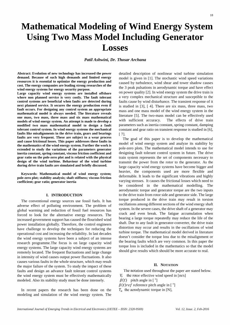
The wind energy system is represented by the Fig.1includes the wind model, aerodynamics, pitch actuator,tower, drive train and generator. The wind model includes theeffects of wind shadow, shear and turbulence. Theaerodynamic model calculates the aerodynamic torque andthrust with the rotor effective wind. When wind speed ismore than rated wind speed the pitch angle is adjusted bythe pitch actuator to maintain the rated rotor speed. Theaerodynamic torque is the input to the drive train. Thedrive train increases the speed of the rotor. Finally thegenerator model includes the generated power calculation.
Fig.1 Wind energy system divided into sub-models
A. Wind Model
Wind speed variations due turbulence and periodic windspeed variations caused by wind shear and wind shadowleads to the dynamic loading of wind turbine. As the airpasses over the earth, it causes friction with ground,buildings, hills, trees and other structures called wind shear.As the blades are rotated, when these are at lower side itexperiences more wind shear. When the rotor effective windspeed is considered for individual blade, it decreases whenblade comes in front of the tower. The wind flow is redirecteddue to the presence of the tower called wind shadow effect.The tower shadow is more dominant in determining the
dynamic torque oscillations compare to wind shear. Windturbulence depends on various environmental factors liketemperature, pressure, humidity as well as the motion of winditself in three dimensions. Fig. 2 shows that effective wind isthe collective effect of wind shear, wind shadow andturbulence.
Fig.2 Effective wind considering wind shear, shadow and turbulence
B. Aerodynamic Model
Aerodynamic torque is transferred from the rotor to thegenerator through drive train. It is given by equation (1)= (1)
The pitch angle can be changed to control the rotor speed.In case of higher wind speed the pitch angle has to increase tomaintain the rated rotor speed. Any fault occurred in case ofpitch angle position may cause the system to go in runawaycondition which is the failure of the system.
In partial load region maximum value of is maintainedby adjusting very small pitch angle where the maximumpower can be captured. In full load region, the rotor speed ismaintained constant by adjusting the pitch angle and the ratedpower is maintained.
The wind acting on the rotor causes aerodynamic thrustin [N] on the tower which makes the tower to sway back
and forth. It is given by equation (2)= (2)
C. Pitch Actuator:
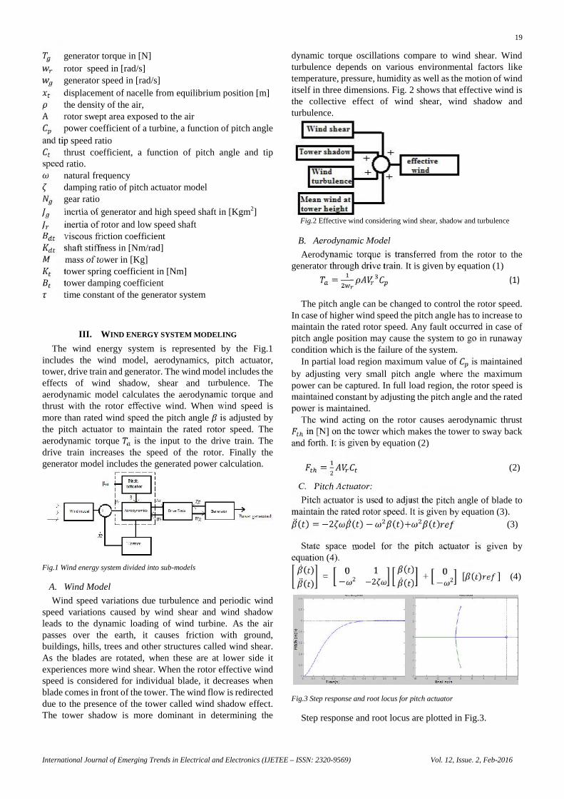
Pitch actuator is used to adjust the pitch angle of blade tomaintain the rated rotor speed. It is given by equation (3). ( ) = −2 ( ) − ( )+ ( ) (3)
State space model for the pitch actuator is given byequation (4). ( )( ) =
0 1− 2 −2 ( )( ) + 0− 2 [ ( ) ] (4)
Fig.3 Step response and root locus for pitch actuator
Step response and root locus are plotted in Fig.3.
20
International Journal of Emerging Trends in Electrical and Electronics (IJETEE – ISSN: 2320-9569) Vol. 12, Issue. 2, Feb-2016
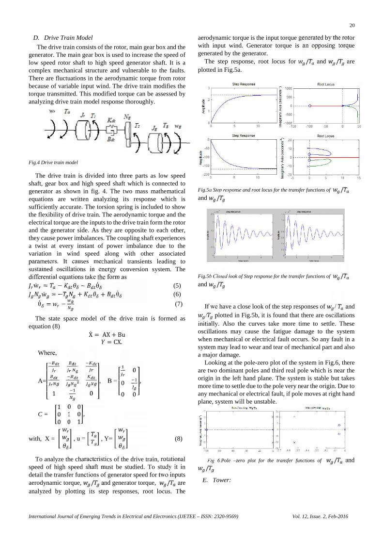
D. Drive Train Model
The drive train consists of the rotor, main gear box and thegenerator. The main gear box is used to increase the speed oflow speed rotor shaft to high speed generator shaft. It is acomplex mechanical structure and vulnerable to the faults.There are fluctuations in the aerodynamic torque from rotorbecause of variable input wind. The drive train modifies thetorque transmitted. This modified torque can be assessed byanalyzing drive train model response thoroughly.
Fig.4 Drive train model
The drive train is divided into three parts as low speedshaft, gear box and high speed shaft which is connected togenerator as shown in fig. 4. The two mass mathematicalequations are written analyzing its response which issufficiently accurate. The torsion spring is included to showthe flexibility of drive train. The aerodynamic torque and theelectrical torque are the inputs to the drive train form the rotorand the generator side. As they are opposite to each other,they cause power imbalances. The coupling shaft experiencesa twist at every instant of power imbalance due to thevariation in wind speed along with other associatedparameters. It causes mechanical transients leading tosustained oscillations in energy conversion system. Thedifferential equations take the form asw = − − θ (5)w = − + + θ (6)
θ = − (7)
The state space model of the drive train is formed asequation (8) X = AX + Bu= CX.
Where,
A=⎣⎢⎢⎢⎡ 1 0 ⎦⎥⎥
⎥⎤, B = ⎣⎢⎢
⎡ 000 0 ⎦⎥⎥⎤,
C =1 0 00 1 00 0 1 ,
with, X = , u = , Y= (8)
To analyze the characteristics of the drive train, rotationalspeed of high speed shaft must be studied. To study it indetail the transfer functions of generator speed for two inputsaerodynamic torque, / and generator torque, / areanalyzed by plotting its step responses, root locus. The
aerodynamic torque is the input torque generated by the rotorwith input wind. Generator torque is an opposing torquegenerated by the generator.
The step response, root locus for / and / areplotted in Fig.5a.
Fig.5a Step response and root locus for the transfer functions of /and /
Fig.5b Closed look of Step response for the transfer functions of /and /
If we have a close look of the step responses of / and/ plotted in Fig.5b, it is found that there are oscillations
initially. Also the curves take more time to settle. Theseoscillations may cause the fatigue damage to the systemwhen mechanical or electrical fault occurs. So any fault in asystem may lead to wear and tear of mechanical part and alsoa major damage.
Looking at the pole-zero plot of the system in Fig.6, thereare two dominant poles and third real pole which is near theorigin in the left hand plane. The system is stable but takesmore time to settle due to the pole very near the origin. Due toany mechanical or electrical fault, if pole moves at right handplane, system will be unstable.
Fig 6.Pole –zero plot for the transfer functions of / and/E. Tower:
21
International Journal of Emerging Trends in Electrical and Electronics (IJETEE – ISSN: 2320-9569) Vol. 12, Issue. 2, Feb-2016
The effective wind speed on the rotor causes thrust force inthe direction of wind on tower. It causes tower accelerationand reduces the effective wind speed of rotor shown in Fig.7.The tower gets displaced from the equilibrium due to thrustby distance . It causes the reduction of rotor effectivespeed. Mathematically the tower can be modeled as equation(9) = − − x (9)
Fig.7 .Rotor effective wind speed affected by tower acceleration
State space function for tower is given by equation (10)xx =0 1 xx +
0 [ ] (10)
Fig.8 Step response and root locus for tower acceleration
The step response and root locus of tower acceleration tostep change in are plotted in Fig.8.
F. Generator:
Generator is a very important component in the windenergy system. It has to work under fluctuating power levelsand tune with the wind variations. The various types ofgenerator i.e. induction type, synchronous type and now aday popularly used doubly fed type induction generator isused. Electric power is generated by the generator, and toenable variable-speed operation, currents in the generator arecontrolled using power electronics. Therefore, powerelectronic converters interface the wind turbine generatoroutput with the utility grid. The first order model of generatorwith converter can be represented by equation (11)= (11)
The power produced by the generator depends on therotational speed of the rotor and the applied load. It isdescribed by the equation (12).ƞ (12)
where ƞ is the efficiency of the generator.
IV. STABILITY ANALYSIS OF WIND TURBINE
Drive train is very important part of the variable speedwind energy system. It is very complex mechanical structure.The frequent mechanical faults in it are due to misalignmentand damaged bearing. The misalignment causes non-uniform
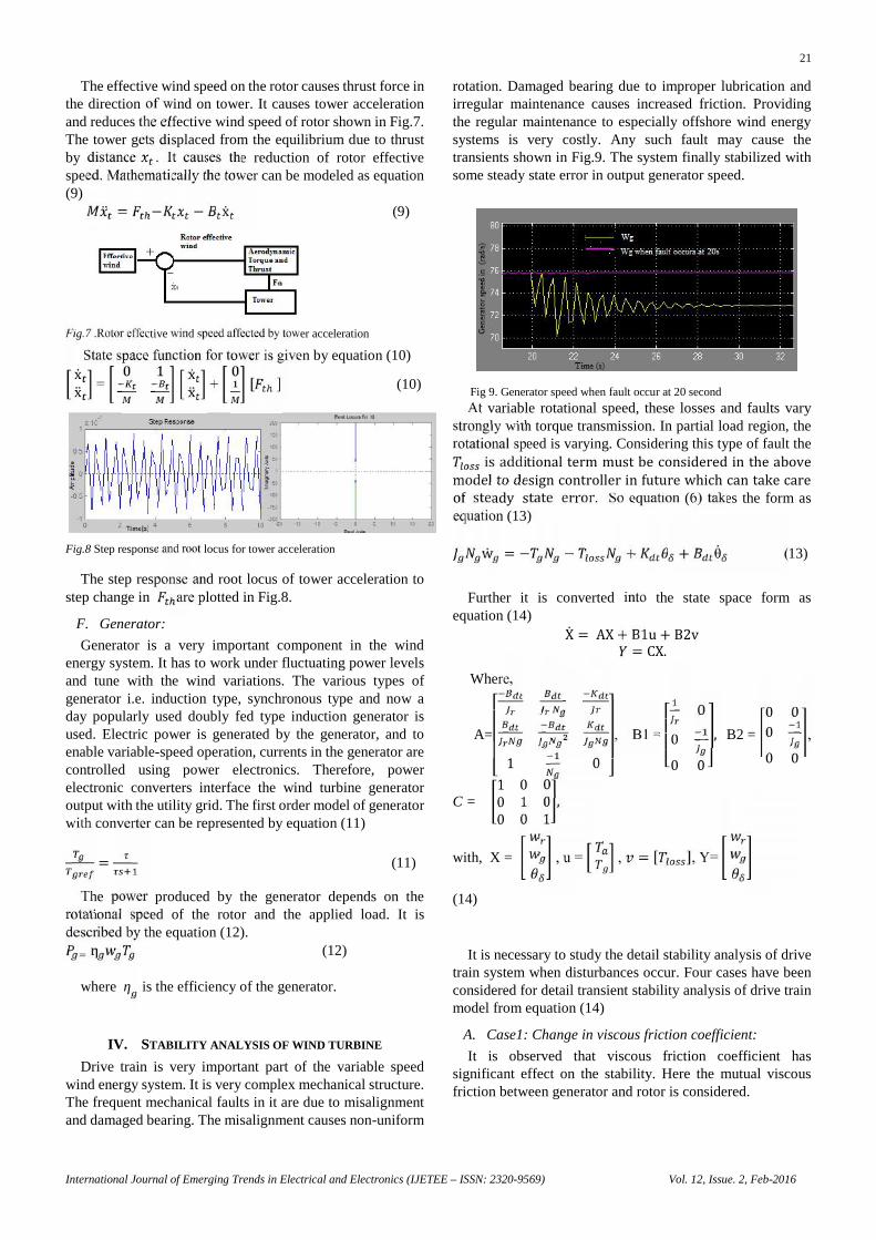
rotation. Damaged bearing due to improper lubrication andirregular maintenance causes increased friction. Providingthe regular maintenance to especially offshore wind energysystems is very costly. Any such fault may cause thetransients shown in Fig.9. The system finally stabilized withsome steady state error in output generator speed.
Fig 9. Generator speed when fault occur at 20 second
At variable rotational speed, these losses and faults varystrongly with torque transmission. In partial load region, therotational speed is varying. Considering this type of fault theis additional term must be considered in the abovemodel to design controller in future which can take careof steady state error. So equation (6) takes the form asequation (13)w = − − + + θ (13)
Further it is converted into the state space form asequation (14) X = AX + B1u+ B2v= CX.
Where,
A=⎣⎢⎢⎢⎡ 1 0 ⎦⎥⎥
⎥⎤, B1 = ⎣⎢⎢
⎡ 000 0 ⎦⎥⎥⎤, B2 =
0 000 0 ,
C =1 0 00 1 00 0 1 ,
with, X = , u = , = [ ], Y=
(14)
It is necessary to study the detail stability analysis of drivetrain system when disturbances occur. Four cases have beenconsidered for detail transient stability analysis of drive trainmodel from equation (14)
A. Case1: Change in viscous friction coefficient:
It is observed that viscous friction coefficient hassignificant effect on the stability. Here the mutual viscousfriction between generator and rotor is considered.
22
International Journal of Emerging Trends in Electrical and Electronics (IJETEE – ISSN: 2320-9569) Vol. 12, Issue. 2, Feb-2016
If we analyze the pole-zero plot of the transfer function /, the real zero moves towards the dominant poles as
increases and thus the oscillatory response improves.But looking at the poles of the system shown in fig. 10, when
is increased by 25%, one pole moves towards right handplane. This causes the instability of the system.
Fig.10 Pole –zero plot for the transfer functions of / and /with 50% increase in
Fig.11 Step response for / and / with 50% increase in
Fig.11 shows the step responses of both the transferfunction are unstable at more by 25%. Fig. 12 shows thetransient response when fault occurred at 20s.
Fig.12 Generator speed when fault occur in drive train with actual and
increased by 25%.
B. Case 2: Change in shaft stiffness:
The rotor inertia constant of the generator is much lowerthan that of the wind turbine. If the shaft stiffness of windenergy system is lesser, the drive train distortion may occurand results in the oscillation in the wind turbine torque duringthe faults.
During grid faults, the electrical torque is significantlyreduced, and therefore the drive train system acts like atorsion spring that gets untwisted. Due to the torsion springcharacteristic of the drive train, the transients are observed ingenerator speed. The large torque produced in the drive trainmay result in torsional oscillations among different sectionsof the wind turbine shaft system. In the severe cases, the driveshaft of a wind turbine generator may crack and even break.The fatigue accumulation when bearing a large torquerepeatedly may reduce the life of the shaft.
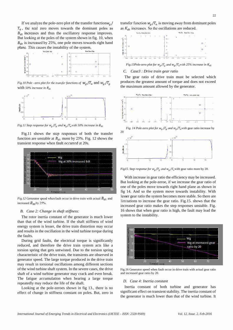
Looking at the pole-zeroes shown in fig 13., there is noeffect of change in stiffness constant on poles. But, zero in
transfer function / is moving away from dominant polesas increases. So the oscillations are reduced.
Fig.13Pole-zero plot for / and / with 25% increase in
C. Case3 : Drive train gear ratio
The gear ratio of drive train must be selected whichproduces the greatest amount of torque and does not exceedthe maximum amount allowed by the generator.
Fig. 14 Pole-zero plot for / and / with gear ratio increase by20
Fig15. Step response for / and / with gear ratio more by 20.
With increase in gear ratio the efficiency may be increased.But looking at the pole-zeroe, if we increase the gear ratio ofone of the poles move towards right hand plane as shown infig 14. And so the system move towards instability. Withlesser gear ratio the system becomes more stable. So there arelimitations to increase the gear ratio. Fig.15. shows that theincreased gear ratio makes the step responses unstable. Fig.16 shows that when gear ratio is high, the fault may lead thesystem to the instability.
Fig.16 Generator speed when fault occur in drive train with actual gear ratioand increased gear ratio by 20.
D. Case 4: Inertia constant
Inertia constant of both turbine and generator hassignificant effect on transient stability. The inertia constant ofthe generator is much lower than that of the wind turbine. It
22
International Journal of Emerging Trends in Electrical and Electronics (IJETEE – ISSN: 2320-9569) Vol. 12, Issue. 2, Feb-2016
If we analyze the pole-zero plot of the transfer function /, the real zero moves towards the dominant poles as
increases and thus the oscillatory response improves.But looking at the poles of the system shown in fig. 10, when
is increased by 25%, one pole moves towards right handplane. This causes the instability of the system.
Fig.10 Pole –zero plot for the transfer functions of / and /with 50% increase in
Fig.11 Step response for / and / with 50% increase in
Fig.11 shows the step responses of both the transferfunction are unstable at more by 25%. Fig. 12 shows thetransient response when fault occurred at 20s.
Fig.12 Generator speed when fault occur in drive train with actual and
increased by 25%.
B. Case 2: Change in shaft stiffness:
The rotor inertia constant of the generator is much lowerthan that of the wind turbine. If the shaft stiffness of windenergy system is lesser, the drive train distortion may occurand results in the oscillation in the wind turbine torque duringthe faults.
During grid faults, the electrical torque is significantlyreduced, and therefore the drive train system acts like atorsion spring that gets untwisted. Due to the torsion springcharacteristic of the drive train, the transients are observed ingenerator speed. The large torque produced in the drive trainmay result in torsional oscillations among different sectionsof the wind turbine shaft system. In the severe cases, the driveshaft of a wind turbine generator may crack and even break.The fatigue accumulation when bearing a large torquerepeatedly may reduce the life of the shaft.
Looking at the pole-zeroes shown in fig 13., there is noeffect of change in stiffness constant on poles. But, zero in
transfer function / is moving away from dominant polesas increases. So the oscillations are reduced.
Fig.13Pole-zero plot for / and / with 25% increase in
C. Case3 : Drive train gear ratio
The gear ratio of drive train must be selected whichproduces the greatest amount of torque and does not exceedthe maximum amount allowed by the generator.
Fig. 14 Pole-zero plot for / and / with gear ratio increase by20
Fig15. Step response for / and / with gear ratio more by 20.
With increase in gear ratio the efficiency may be increased.But looking at the pole-zeroe, if we increase the gear ratio ofone of the poles move towards right hand plane as shown infig 14. And so the system move towards instability. Withlesser gear ratio the system becomes more stable. So there arelimitations to increase the gear ratio. Fig.15. shows that theincreased gear ratio makes the step responses unstable. Fig.16 shows that when gear ratio is high, the fault may lead thesystem to the instability.
Fig.16 Generator speed when fault occur in drive train with actual gear ratioand increased gear ratio by 20.
D. Case 4: Inertia constant
Inertia constant of both turbine and generator hassignificant effect on transient stability. The inertia constant ofthe generator is much lower than that of the wind turbine. It
23
International Journal of Emerging Trends in Electrical and Electronics (IJETEE – ISSN: 2320-9569) Vol. 12, Issue. 2, Feb-2016
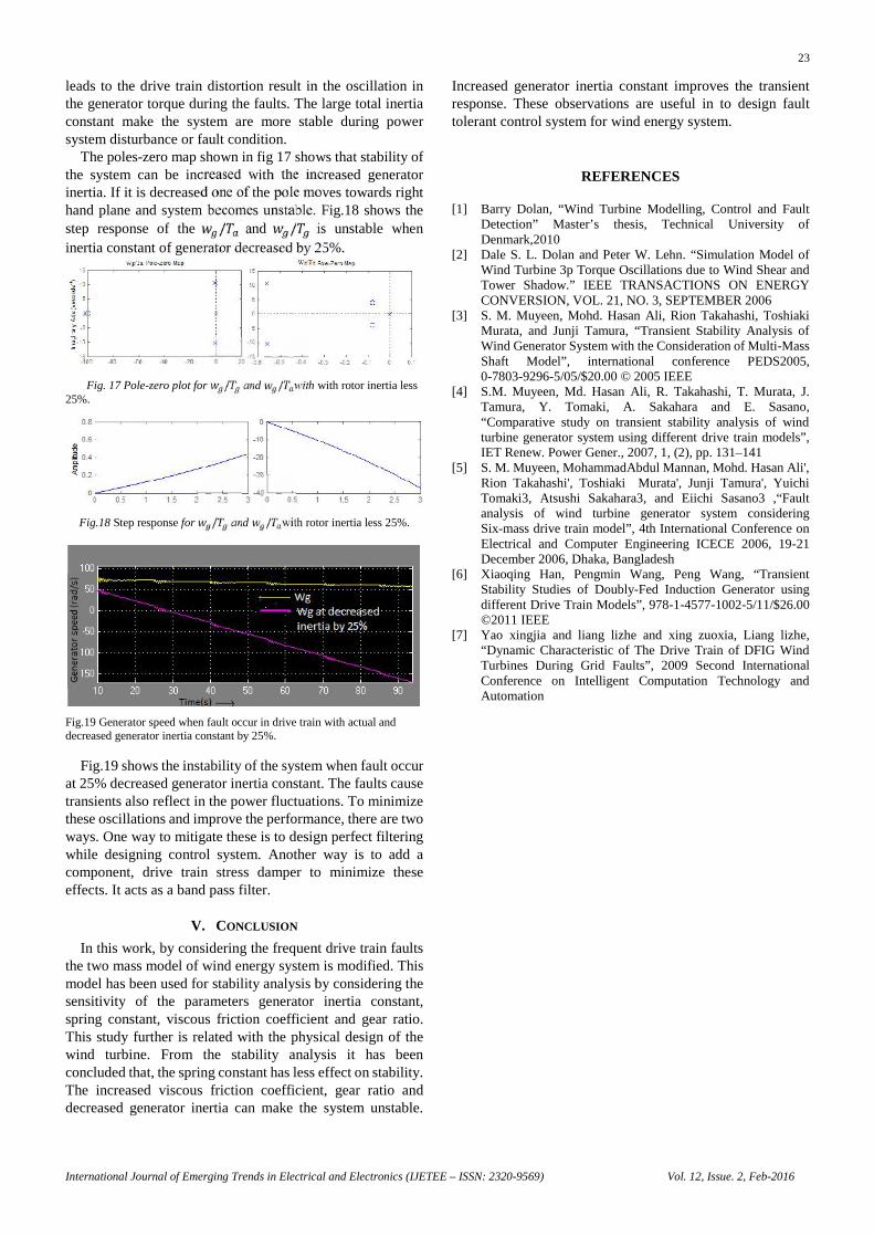
leads to the drive train distortion result in the oscillation inthe generator torque during the faults. The large total inertiaconstant make the system are more stable during powersystem disturbance or fault condition.
The poles-zero map shown in fig 17 shows that stability ofthe system can be increased with the increased generatorinertia. If it is decreased one of the pole moves towards righthand plane and system becomes unstable. Fig.18 shows thestep response of the / and / is unstable wheninertia constant of generator decreased by 25%.
Fig. 17 Pole-zero plot for / and / with with rotor inertia less25%.
Fig.18 Step response for / and / with rotor inertia less 25%.
Fig.19 Generator speed when fault occur in drive train with actual anddecreased generator inertia constant by 25%.
Fig.19 shows the instability of the system when fault occurat 25% decreased generator inertia constant. The faults causetransients also reflect in the power fluctuations. To minimizethese oscillations and improve the performance, there are twoways. One way to mitigate these is to design perfect filteringwhile designing control system. Another way is to add acomponent, drive train stress damper to minimize theseeffects. It acts as a band pass filter.
V. CONCLUSION
In this work, by considering the frequent drive train faultsthe two mass model of wind energy system is modified. Thismodel has been used for stability analysis by considering thesensitivity of the parameters generator inertia constant,spring constant, viscous friction coefficient and gear ratio.This study further is related with the physical design of thewind turbine. From the stability analysis it has beenconcluded that, the spring constant has less effect on stability.The increased viscous friction coefficient, gear ratio anddecreased generator inertia can make the system unstable.
Increased generator inertia constant improves the transientresponse. These observations are useful in to design faulttolerant control system for wind energy system.
REFERENCES
[1] Barry Dolan, “Wind Turbine Modelling, Control and FaultDetection” Master’s thesis, Technical University ofDenmark,2010
[2] Dale S. L. Dolan and Peter W. Lehn. “Simulation Model ofWind Turbine 3p Torque Oscillations due to Wind Shear andTower Shadow.” IEEE TRANSACTIONS ON ENERGYCONVERSION, VOL. 21, NO. 3, SEPTEMBER 2006
[3] S. M. Muyeen, Mohd. Hasan Ali, Rion Takahashi, ToshiakiMurata, and Junji Tamura, “Transient Stability Analysis ofWind Generator System with the Consideration of Multi-MassShaft Model”, international conference PEDS2005,0-7803-9296-5/05/$20.00 © 2005 IEEE
[4] S.M. Muyeen, Md. Hasan Ali, R. Takahashi, T. Murata, J.Tamura, Y. Tomaki, A. Sakahara and E. Sasano,“Comparative study on transient stability analysis of windturbine generator system using different drive train models”,IET Renew. Power Gener., 2007, 1, (2), pp. 131–141
[5] S. M. Muyeen, MohammadAbdul Mannan, Mohd. Hasan Ali',Rion Takahashi', Toshiaki Murata', Junji Tamura', YuichiTomaki3, Atsushi Sakahara3, and Eiichi Sasano3 ,“Faultanalysis of wind turbine generator system consideringSix-mass drive train model”, 4th International Conference onElectrical and Computer Engineering ICECE 2006, 19-21December 2006, Dhaka, Bangladesh
[6] Xiaoqing Han, Pengmin Wang, Peng Wang, “TransientStability Studies of Doubly-Fed Induction Generator usingdifferent Drive Train Models”, 978-1-4577-1002-5/11/$26.00©2011 IEEE
[7] Yao xingjia and liang lizhe and xing zuoxia, Liang lizhe,“Dynamic Characteristic of The Drive Train of DFIG WindTurbines During Grid Faults”, 2009 Second InternationalConference on Intelligent Computation Technology andAutomation
23
International Journal of Emerging Trends in Electrical and Electronics (IJETEE – ISSN: 2320-9569) Vol. 12, Issue. 2, Feb-2016
leads to the drive train distortion result in the oscillation inthe generator torque during the faults. The large total inertiaconstant make the system are more stable during powersystem disturbance or fault condition.
The poles-zero map shown in fig 17 shows that stability ofthe system can be increased with the increased generatorinertia. If it is decreased one of the pole moves towards righthand plane and system becomes unstable. Fig.18 shows thestep response of the / and / is unstable wheninertia constant of generator decreased by 25%.
Fig. 17 Pole-zero plot for / and / with with rotor inertia less25%.
Fig.18 Step response for / and / with rotor inertia less 25%.
Fig.19 Generator speed when fault occur in drive train with actual anddecreased generator inertia constant by 25%.
Fig.19 shows the instability of the system when fault occurat 25% decreased generator inertia constant. The faults causetransients also reflect in the power fluctuations. To minimizethese oscillations and improve the performance, there are twoways. One way to mitigate these is to design perfect filteringwhile designing control system. Another way is to add acomponent, drive train stress damper to minimize theseeffects. It acts as a band pass filter.
V. CONCLUSION
In this work, by considering the frequent drive train faultsthe two mass model of wind energy system is modified. Thismodel has been used for stability analysis by considering thesensitivity of the parameters generator inertia constant,spring constant, viscous friction coefficient and gear ratio.This study further is related with the physical design of thewind turbine. From the stability analysis it has beenconcluded that, the spring constant has less effect on stability.The increased viscous friction coefficient, gear ratio anddecreased generator inertia can make the system unstable.
Increased generator inertia constant improves the transientresponse. These observations are useful in to design faulttolerant control system for wind energy system.
REFERENCES
[1] Barry Dolan, “Wind Turbine Modelling, Control and FaultDetection” Master’s thesis, Technical University ofDenmark,2010
[2] Dale S. L. Dolan and Peter W. Lehn. “Simulation Model ofWind Turbine 3p Torque Oscillations due to Wind Shear andTower Shadow.” IEEE TRANSACTIONS ON ENERGYCONVERSION, VOL. 21, NO. 3, SEPTEMBER 2006
[3] S. M. Muyeen, Mohd. Hasan Ali, Rion Takahashi, ToshiakiMurata, and Junji Tamura, “Transient Stability Analysis ofWind Generator System with the Consideration of Multi-MassShaft Model”, international conference PEDS2005,0-7803-9296-5/05/$20.00 © 2005 IEEE
[4] S.M. Muyeen, Md. Hasan Ali, R. Takahashi, T. Murata, J.Tamura, Y. Tomaki, A. Sakahara and E. Sasano,“Comparative study on transient stability analysis of windturbine generator system using different drive train models”,IET Renew. Power Gener., 2007, 1, (2), pp. 131–141
[5] S. M. Muyeen, MohammadAbdul Mannan, Mohd. Hasan Ali',Rion Takahashi', Toshiaki Murata', Junji Tamura', YuichiTomaki3, Atsushi Sakahara3, and Eiichi Sasano3 ,“Faultanalysis of wind turbine generator system consideringSix-mass drive train model”, 4th International Conference onElectrical and Computer Engineering ICECE 2006, 19-21December 2006, Dhaka, Bangladesh
[6] Xiaoqing Han, Pengmin Wang, Peng Wang, “TransientStability Studies of Doubly-Fed Induction Generator usingdifferent Drive Train Models”, 978-1-4577-1002-5/11/$26.00©2011 IEEE
[7] Yao xingjia and liang lizhe and xing zuoxia, Liang lizhe,“Dynamic Characteristic of The Drive Train of DFIG WindTurbines During Grid Faults”, 2009 Second InternationalConference on Intelligent Computation Technology andAutomation