Embed Size (px)
Citation preview

IJCTA, 8(3), 2015, pp. 915-921© International Science Press
Mathematical Modeling of Packed Column for NOx Gas Removal using Hydrogen Peroxide SolutionC. Maheswari*, R. Vinoth, L. Kanimozhi and B. Meenakshipriya
Abstract: This work mainly focused on the design and modeling of packed column for NOx gas removal using hydrogen peroxide absorbent. Mathematical modeling was carried out for the column with packing material Intalox ceramic saddles with 6 mm diameter. The de-nitrification process was carried out to make the NO removal process such that various parameters such as packed column sizing, packing material, absorbents used were determined for the NOx removal process by wet scrubbing technique. This modeling determines of liquid flow rate, diameter, and packing height, which offers enhanced the absorption NOx of gas, mathematical modelling is based on two film theory of gas liquid absorption.
Keywords: NOx emission; absorption; two film theory; packed column.
1. INTRODUCTIONNitric oxide is emitted from the automobile engines, fossil fuel power plants. These emitted gaseous reacts with atmospheric air and causes severe effects in the environmental. The Nitric oxide gas converted in to nitric acid, which was a main cause of the acid rain formation. Furthermore, both NO and NO2 contribute in ozone layer depletion. There are various types of emission controlling approaches develop by the industrialists and researchers such as selective catalytic reduction (SCR), selective non-catalytic reduction (SNCR), and adsorption and wet scrubbing. Other than this, a new upgrading method for effluent reduction process is wet scrubbing process, which is the most effective method to abate the gas particle through the mass transfer technique. Wet scrubbers have some unique characteristics useful for fine particulate control.
Absorption with chemical reaction involves removing the impurities from gas phase and dissolving them into the liquid phase by making a chemical reaction between them. The absorption process is described by the mathematical model based on a two-film theory of gas-liquid absorption. The two film theory proposed by Whitman (1923) is the simplest theory designed for mass transfer analysis. The most commonly used device for absorption process is a packed column, since packed area in the column is used to develop more interfacial area between gas and liquid which increases the absorption rate [11]. NOx is more challenging to take away from the wet scrubbers, because most of it is in the form of nitric oxide (NO), which having a very low solubility. The wet scrubbing process is implemented through, the newly designed packed column for NOx emission control process and the main absorbent used for the wet scrubbing process is hydrogen peroxide which is used as absorbent. To rise the absorption rate of NOx, oxidizing agents were get together effectively both in the gas phase (ozone, chlorine dioxide, hydrogen peroxide,) [9] & [6] or in the liquid phase (potassium permanganate, sodium chlorite etc.). An oxidizing
Department of Mechatronics Engineering, Kongu Engineering College, Perundurai – 638052*[email protected].
916
process using hydrogen peroxide in the scrubbing solution appears to be very attractive, as it results in the production of valuable nitric acid without generating any other polluting byproduct [10].
2. ABSORBENT SELECTION PARAMETERSBased on the literature survey various type of absorbents were used in the packed column are tabulated in table 1. It is clear that various absorbents are used for NOx emission control process such as NaClO2, aqueous HNO3, H2O2, potassium permanganate, NH3 etc., Hence H2O2 is considered as an optimized absorbent for NOx removal process which can be used in the modeling of packed column.
Table 1 Absorbent selection
Author Absorbents used Mole conc./ feed rate of absorbent
Removal efficiency Height of packed column
H.K LEE et al. [7] NaClO2 0-50ml/min 67% ID-0.015m,height-1.0m
Collins et al [1]. H2O2 Molar ratio-1.0 >90% Height 1.5m Kasper et al[6]. HNO3with added
H2O2 HNO3-0-2M, H2O2-0.02M
90% Height 2m
3. MODELING OF THE PACKED COLUMN FOR NO EMISSION CONTROL PROCESS
3.1 Packed ColumnPacked bed columns are ultimately utilized in absorption, desorption, and direct heat transfer processes in chemical, environmental protection such as processes in thermal power stations like water purification.
3.2 Design Of Packed Column
Figure 1: schematic diagram of packed column
Figure 1 shows the schematic representation of packed column, which consists of liquid sprayer, gas and liquid inlet, gas distributor and a packed bed. The liquid solvent is allowed to enter the column at the top through a liquid distributor and then it flows down through the surfaces of the packing materials. The gas phase enters at the bottom of the column, which flows upward through the packing materials, through
C. Maheswari, R. Vinoth, L. Kanimozhi and B. Meenakshipriya
917
which mass transfer takes place from the gas to liquid films. Better performance of the column is obtained by properly designing the parameters of the column such as absorbent used, diameter, total height, packing material, type of packing material used, packing height and Liquid/Gas (L/G) ratio. Packed column and its parameters used by the various researchers are shown in the table 2
Table 2 Parameters of packed column
Parameters Thomas et al.[10] Vanderschuren et al.[5] Kenig et al.[8]
Diameter(m) 0.045 0.045 0.025
Height(m) 0.45 0.45 1
Flow rate of liquid(lph) 37.4 30.7 19.6
Flow rate of gas(m^3/s) 2.8*10^-4 2.8*10^-4 49*10^-5
Packing material 10mm glass rasching ring 10mm glass Rasching ring 12.5mm ceramic rasching ring
3.3 Mathematical Modeling of the Packed Column
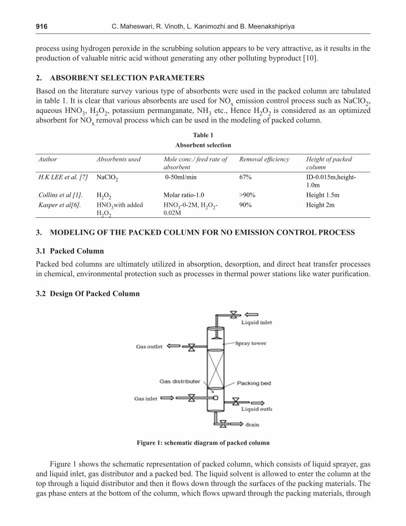
3.3.1 Determination of Lm/Gm RatioThe minimum liquid and gas requirement are determine based on solubility of gas (NO) in a liquid (aqueous nitric acid) which determines the amount of pollutant absorbed from the gas phase to liquid phase. The mostly used method for analyzing the solubility data is to use an equilibrium diagram. It is a plot between mole fraction of solute in the liquid phase denoted as ‘X’ and the mole fraction of solute in the gas phase denoted as ‘Y’ which is indicated in figure 2
Figure 2: Equilibrium diagram
To remove the required amount of NO the temperature is to be maintained at 20°C. Let us take following assumption,
Inlet concentration 1y 1% of NO by volume=
=0.01 mole fraction of NO
Outlet concentration 2y 98% reduction of NO from inlet concentration=
Mathematical Modeling of Packed Column for NOx Gas Removal using Hydrogen Peroxide Solution
918
1=(2%)(y )
=(0.002)*(0.01)
=0.0002 mole fraction of NO
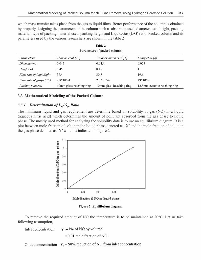
For a constant flow rate of gas, the increase in liquid flow rate causes the liquid to fill completely in the packing and stops the liquid flow into the packed area. Based on the literature review the following parameters used to modeling packed column. Hendry’s constant m =0.0014 which is taken from the Compilation of Henry’s Law Constants for Inorganic and Organic Species of Potential Importance in Environmental Chemistry and from the figure 3, flooding factor K4 = 0.7 then K4 -Flooding factor (0.6 to 0.8); Gm -Gas mass flow rate (kg/sec); Lm -Liquid mass flow rate (kg/sec) and m - Henry’s constant.
5
Henry’s Law Constants for Inorganic and Organic Species of Potential Importance in Environmental Chemistry and from the figure 3, flooding factor K4 = 0.7 then K4 -Flooding factor (0.6 to 0.8); Gm -Gas mass flow rate (kg/sec); Lm -Liquid mass flow rate (kg/sec) and m - Henry’s constant.
Let 𝐺� = 1𝑚�ℎ𝑟�
𝐺� = 3.383 ∗ 10�� 𝐾𝑔 𝑠𝑒𝑐�
����
= ��������� ������
(1)
Substituting the flooding factor and henry’s constant in the equation (1)
𝐿� = 0.002285𝐾𝑔 𝑠𝑒𝑐�
Converting into the mass function
𝐿� = 4.44 𝑙 ℎ𝑟�
Hence, the liquid flow rate to the packed column (Lm) is chosen as 5 lph approximately for experimental analysis.
3.3.2. DETERMINATION OF PACKED COLUMN DIAMETER
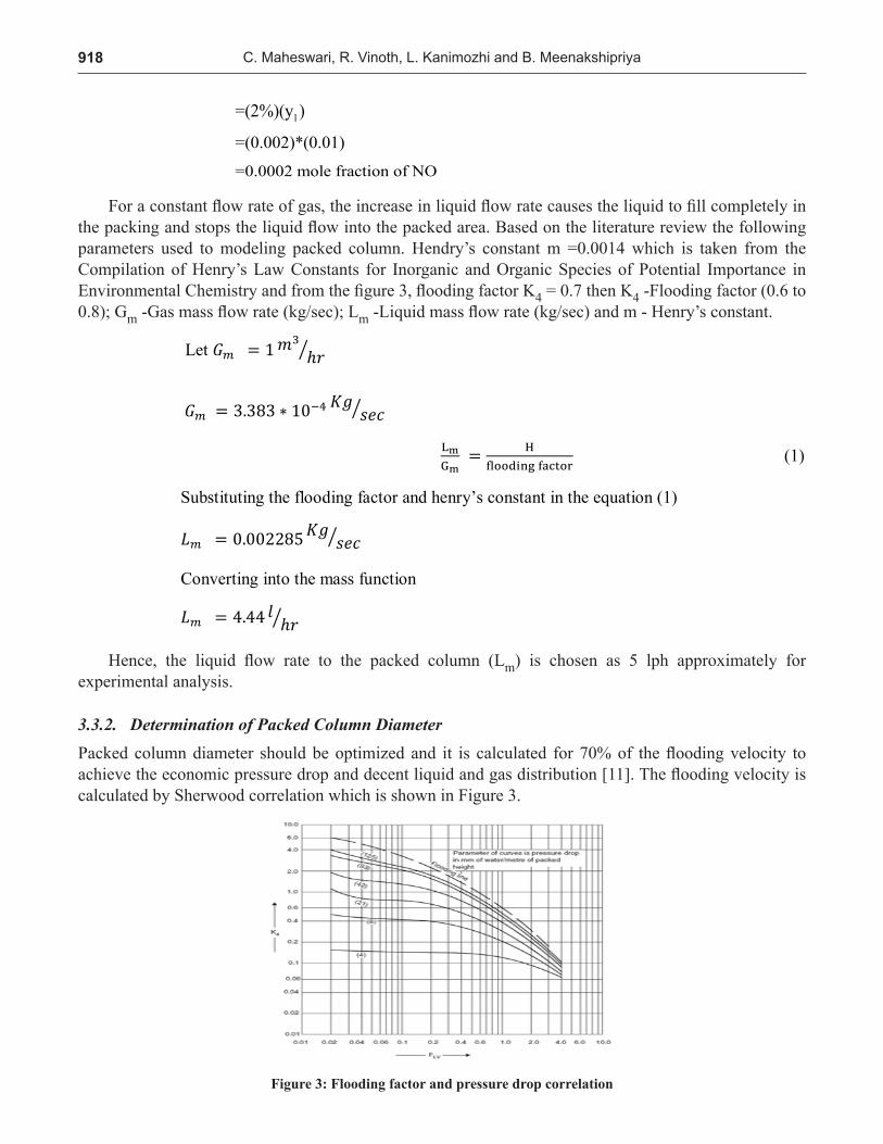
Packed column diameter should be optimized and it is calculated for 70% of the flooding velocity to achieve the economic pressure drop and decent liquid and gas distribution [11]. The flooding velocity is calculated by Sherwood correlation which is shown in Figure 3.
Figure 3: Flooding factor and pressure drop correlation
Hence, the liquid flow rate to the packed column (Lm) is chosen as 5 lph approximately for experimental analysis.
3.3.2. Determination of Packed Column DiameterPacked column diameter should be optimized and it is calculated for 70% of the flooding velocity to achieve the economic pressure drop and decent liquid and gas distribution [11]. The flooding velocity is calculated by Sherwood correlation which is shown in Figure 3.
Figure 3: Flooding factor and pressure drop correlation
C. Maheswari, R. Vinoth, L. Kanimozhi and B. Meenakshipriya

919
From the Figure 3, the flooding factor (K4) is identified for the corresponding pressure drop (FLV) in the packed column and it is used to calculate the column diameter. The pressure drop (FLV) is represented as
6
From the Figure 3, the flooding factor (K4) is identified for the corresponding pressure drop (FLV) in the packed column and it is used to calculate the column diameter. The pressure drop (FLV) is represented as
𝐴𝑏𝑠𝑐𝑖𝑠𝑠𝑎(𝐹��) = ��∗
��∗�������.�
(2)
𝐹�� = ���������
(3)
where, ρG –gas (NO) density (1.21 kg/m3), ρL -liquid (aqueous H2SO4) density (1857 kg/m3), Gm -molar flow rate of gas (0.0003383 kg/sec) and Lm -molar flow rate of liquid (0.002285 kg/sec). By substituting the molar flow rate of liquid and gas and also their corresponding densities in equation (6) then, we get F�� = 0.1724 . Thus the calculated pressure drop (FLV) is 0.1724. Another factor to be considered while determining the liquid flow rate into the column is flooding. It is the gas velocity at which the liquid droplets become entrained in the escaping gas stream and it is expressed as
(4)
From the flooding factor, the gas mass flow rate / column cross sectional area ( *wV ) is
determined and it is expressed as
𝑉� = �����(�����)
��.����������.��
�.�
(5)
𝑉� = 2.15𝐾𝑔 𝑚�𝑠�
Based on the above parameters, the calculated gas mass flow rate / column cross sectional area ( *
wV ) is 2.15 kg/m2s.
The area of the packed column (a) is calculated as
𝐴 = ����
(6)
𝐴 = 1.573 ∗ 10��𝑚� D= 0.0447 ≈ 0.045m
Hence the area of the packed column is determined as A=0.001573m2 and the diameter of the packed column is D= 0.045m
3.3.3. DETERMINATION OF PACKING HEIGHT OF THE PACKED COLUMN
The packing height directly refers to the depth of packing material required to do the maximum required removal efficiency. Computation of packed height (Z) of the column is expressed as,
4m
m
mLKG
where, ρG –gas (NO) density (1.21 kg/m3), ρL -liquid (aqueous H2SO4) density (1857 kg/m3), Gm -molar flow rate of gas (0.0003383 kg/sec) and Lm -molar flow rate of liquid (0.002285 kg/sec). By substituting the molar flow rate of liquid and gas and also their corresponding densities in equation (6) then, we get . Thus the calculated pressure drop (FLV) is 0.1724. Another factor to be considered while determining the liquid flow rate into the column is flooding. It is the gas velocity at which the liquid droplets become entrained in the escaping gas stream and it is expressed as
4
m
m
mLKG
=
(4)
From the flooding factor, the gas mass flow rate / column cross sectional area (*
wV ) is determined and it is expressed as
6
From the Figure 3, the flooding factor (K4) is identified for the corresponding pressure drop (FLV) in the packed column and it is used to calculate the column diameter. The pressure drop (FLV) is represented as
𝐴𝑏𝑠𝑐𝑖𝑠𝑠𝑎(𝐹��) = ��∗
��∗�������.�
(2)
𝐹�� = ���������
(3)
where, ρG –gas (NO) density (1.21 kg/m3), ρL -liquid (aqueous H2SO4) density (1857 kg/m3), Gm -molar flow rate of gas (0.0003383 kg/sec) and Lm -molar flow rate of liquid (0.002285 kg/sec). By substituting the molar flow rate of liquid and gas and also their corresponding densities in equation (6) then, we get F�� = 0.1724 . Thus the calculated pressure drop (FLV) is 0.1724. Another factor to be considered while determining the liquid flow rate into the column is flooding. It is the gas velocity at which the liquid droplets become entrained in the escaping gas stream and it is expressed as
(4)
From the flooding factor, the gas mass flow rate / column cross sectional area ( *wV ) is
determined and it is expressed as
𝑉� = �����(�����)
��.����������.��
�.�
(5)
𝑉� = 2.15𝐾𝑔 𝑚�𝑠�
Based on the above parameters, the calculated gas mass flow rate / column cross sectional area ( *
wV ) is 2.15 kg/m2s.
The area of the packed column (a) is calculated as
𝐴 = ����
(6)
𝐴 = 1.573 ∗ 10��𝑚� D= 0.0447 ≈ 0.045m
Hence the area of the packed column is determined as A=0.001573m2 and the diameter of the packed column is D= 0.045m
3.3.3. DETERMINATION OF PACKING HEIGHT OF THE PACKED COLUMN
The packing height directly refers to the depth of packing material required to do the maximum required removal efficiency. Computation of packed height (Z) of the column is expressed as,
4m
m
mLKG
Based on the above parameters, the calculated gas mass flow rate / column cross sectional area (*
wV ) is 2.15 kg/m2s.
The area of the packed column (a) is calculated as
6
From the Figure 3, the flooding factor (K4) is identified for the corresponding pressure drop (FLV) in the packed column and it is used to calculate the column diameter. The pressure drop (FLV) is represented as
𝐴𝑏𝑠𝑐𝑖𝑠𝑠𝑎(𝐹��) = ��∗
��∗�������.�
(2)
𝐹�� = ���������
(3)
where, ρG –gas (NO) density (1.21 kg/m3), ρL -liquid (aqueous H2SO4) density (1857 kg/m3), Gm -molar flow rate of gas (0.0003383 kg/sec) and Lm -molar flow rate of liquid (0.002285 kg/sec). By substituting the molar flow rate of liquid and gas and also their corresponding densities in equation (6) then, we get F�� = 0.1724 . Thus the calculated pressure drop (FLV) is 0.1724. Another factor to be considered while determining the liquid flow rate into the column is flooding. It is the gas velocity at which the liquid droplets become entrained in the escaping gas stream and it is expressed as
(4)
From the flooding factor, the gas mass flow rate / column cross sectional area ( *wV ) is
determined and it is expressed as
𝑉� = �����(�����)
��.����������.��
�.�
(5)
𝑉� = 2.15𝐾𝑔 𝑚�𝑠�
Based on the above parameters, the calculated gas mass flow rate / column cross sectional area ( *
wV ) is 2.15 kg/m2s.
The area of the packed column (a) is calculated as
𝐴 = ����
(6)
𝐴 = 1.573 ∗ 10��𝑚� D= 0.0447 ≈ 0.045m
Hence the area of the packed column is determined as A=0.001573m2 and the diameter of the packed column is D= 0.045m
3.3.3. DETERMINATION OF PACKING HEIGHT OF THE PACKED COLUMN
The packing height directly refers to the depth of packing material required to do the maximum required removal efficiency. Computation of packed height (Z) of the column is expressed as,
4m
m
mLKG
Hence the area of the packed column is determined as A=0.001573m2 and the diameter of the packed column is D= 0.045m
3.3.3. Determination of Packing Height of the Packed ColumnThe packing height directly refers to the depth of packing material required to do the maximum required removal efficiency. Computation of packed height (Z) of the column is expressed as,
Z = HOG NOG (7)
Where NOG represents the number of transfer units and HOG represents height of transfer units. The number of transfer unit for gas phase is calculated graphically by figure 4 and it is represented as,
N y
yOG = ln 1
2 (8)
Mathematical Modeling of Packed Column for NOx Gas Removal using Hydrogen Peroxide Solution

920
NOG = 1.6
Determination of absorption factor (m Gm/Lm)
Figure 4: Colburn diagram [11].
Height of the transfer unit is taken between 0.3 to 1.2 m
Z = HOG NOG = 1.6 (9)
Z = 0.48m
From these calculated parameters the packed column design has been determined and tabulated in table 3 and its photographic view is shown in figure 5,
Figure 5: Photographic view of the packed column
C. Maheswari, R. Vinoth, L. Kanimozhi and B. Meenakshipriya

921
Table 3 Calculated parameter of packed column
S. no Parameter Calculated value
1 Liquid flow rate to the packed column 5-10lph
2 Gas flow rate to the packed column 1 m3/hr
3 Packed column height 0.70m
4 Packed column diameter 0.045m
5 Packed area 0.48m
6 Packing materials Intalox ceramic saddles with 6 mm diameter
7 Absorbents NaClO2, H2O2, HNO3, HNO3with added H2O2
8 Inlet concentration of NO 100 – 1000 ppm
4. CONCLUSIONThe mathematical modeling is carried out to improve the NOx removal efficiency using the mixed gas analysis. The packed column sizing, packing material, absorbents used were determined for the NO removal process using wet scrubbing process. The mathematical modeling shows that the great removal efficiency was obtained for NOx removal is by using the hydrogen peroxide as absorbent, which gives more than more efficient removal when externally added to the aqueous HNO3.
References[1] Collins and Michelle M. (2001). “Pilot-scale evaluation of H2O2 injection to control NOx Emissions.” Journal of
environmental engineering Vol.127.4 pp. 329-336.
[2] Bal Raj Deshwal Si Hyun Lee Jong Hyeon Jung. Byung Hyun Shon and Hyung Keun Lee (2008). “Study on the removal of NOx from simulated flue gas using acidic NaClO2 solution.” Journal of Environmental Sciences Vol.20 pp. 33-38
[3] Liemans I. Alban B. Trainier J.P. and Thomas D. (2011). “SOx and NOx absorbtion based removal into acidic conditions for the flue gas treatment in oxy-fuel combustion.” Energy Procecedia. Vol.4, pp. 2847-2854.
[4] Gostomczyk M.A. and Kordylewski W. (2010). “Simultaneous NOx and SO2 removal in wet and semi-dry FGD.” Archivum Combustions. Vol.30 pp.1-2
[5] John Kasper M. Christian A. Clausen and David Cooper C. (2012). “Control of Nitrogen Oxide Emissions by Hydrogen Peroxide-Enhanced Gas-Phase Oxidation of Nitric Oxide.” Journal of the Air & Waste Management Association Vol. 46:2. pp. 127-133.
[6] Lee Hyung-Keun. Bal Raj Deshwal. and Kyung-Seun Yoo. (2005). “Simultaneous removal of SO2 and NO by sodium chlorite solution in wetted-wall column”. Korean Journal of Chemical Engineering Vol. 22.2. pp. 208-213.
[7] Kenig Hüpen Bernhard and Eugeny Y(2005). “Rigorous modeling of NOx absorption in tray and packed columns.” Chemical Engineering Science. Vol. 60.22 pp. 6462-6471.
[8] Takahashi, S. Azuhata S, Taki, T, Akimoto, H, Hishinuma T. “Oxidation of nitrogen monoxide in a waste gas.” Japan Patent 79 37,095 1979 (Cl CO1 B 21/36); Chem. Abstr, P78463b.
[9] Thomas, D., and J. Vanderschuren (1997). “Modeling of NOx Absorption into Nitric Acid Solutions Containing Hydrogen Peroxide.” Industrial & Engineering Chemistry Research, 36 (8), pp. 3315-3322.
[10] Coulsion & Richardson 1991, “Chemical Engineering Design”. Elsevier Butterworth-Heinemann, Oxford, pp.587-615.
Mathematical Modeling of Packed Column for NOx Gas Removal using Hydrogen Peroxide Solution