Embed Size (px)
Citation preview

Contents lists available at ScienceDirect
Materials Today Communications
journal homepage: www.elsevier.com/locate/mtcomm
Experimental investigation on low-velocity impact response of woodskinned sandwich composites with different core configurations
T.K. Demircioğlua, F. Balıkoğlua, O. İnala, N. Arslanb, İ. Aya, A. Ataşa,⁎a Department of Mechanical Engineering, Balikesir University, Balikesir, 10145, TurkeybDepartment of Energy Systems Engineering, Manisa Celal Bayar University, Manisa, Turkey
A R T I C L E I N F O
Keywords:Wood skinSandwich structuresImpact behaviourDamage
A B S T R A C T
In this paper, an experimental investigation on the low-velocity impact response of wood skinned hybridsandwich composites was presented. Several alternative design configurations were developed by using rubber-cork and E-glass composite layers between the foam core and wood skin in order to improve the impact per-formance of conventional sandwich composites. Low-velocity impact (LVI) testing was performed using a dropweight test machine at different impact energies and destructive cross-sectioning was performed to examine theinterior damage growth and penetration depth of the specimens. The impact performance of the specimens wasevaluated in terms of energy absorption capacity, maximum contact force and penetration depth. The multi-coredesign concept significantly improved the energy absorption capacity with a reduced extent of impact induceddamage. The proportion of recyclable materials in each configuration and the energy absorption level per unitcost were also presented for the interest of product designers.
1. Introduction
Recyclable and sustainable materials in structural applications arebecoming increasingly popular due to the strict environmental andlegislative restrictions. Although fibre reinforced plastic (FRP) sheetmaterials have been extensively used to develop advanced sandwichstructures in order to maximise the specific bending rigidity andstrength, they are relatively unsustainable as a result of difficulties inrecycling processes. Thus, renewable materials like woods are emergingas a possible alternative to non-renewable materials [1–3]. For in-stance, wood-based eco-structures are widely used for meeting the re-quirements of marine, automotive and environmental-friendly buildingapplications [4,5]. For marine applications as an example, wood basedsandwich structures are mainly used as components of the decks, par-titions or elements for ceilings and floor structures [6]. In addition toconventional sandwich configurations, an effective combination ofdifferent foam, wood and cork materials have been used as skin andcore materials, aiming at superior properties such as low density, goodthermal and acoustic insulation [7–12].
During service life, sandwich structures experience low velocityimpact loadings such as tool drop during manufacturing or main-tenance, moorings or floating objects, ice floes and debris [13]. It isgenerally accepted that low-velocity impacts (LVI) occur at velocitiesbelow 10m/s, and can reduce the strength of whole structure under
quasi-static and dynamic loads due to the localised internal skin and/orcore damage [14,15].
It was shown that the increased core density and the skin thicknessimproves the LVI damage resistance of foam core sandwich composites[16–19]. As an alternative, hybrid sandwich structure concepts havebeen introduced in order to increase the LVI resistance with inter-mediate layers strategically placed between the face sheets and the corematerial [20]. It was observed that introducing ductile intermediatelayers beneath external skins in foam core sandwiches improved pro-tection against core crushing under LVI loadings [21–24]. On the otherhand, using a stiffer composite sheet into a traditional single sandwichstructure decreased the local effect of the impact energy and so it wasspread in a wider area within the structure [25,26]. Experimental re-sults indicated that an increased damage resistance may be obtained asa function of the mechanical properties of the intermediate layers andtheir location [21–26].
Eco-friendly structures receive increasing attention due to theirenvironmental benefits such as recyclability and sustainability. Despitetheir popularity, they have intrinsically lower mechanical propertieswhich have to be complemented with synthetic materials to formstronger hybrid structures. Wood materials are relatively brittle andabsorb lower specific energy (J/kgm2) under LVI loadings [13,27]. Forinstance, balsa wood cores perform well under static loading, but theyfail catastrophically under impact loading due to the low fracture
https://doi.org/10.1016/j.mtcomm.2018.08.003Received 26 May 2018; Received in revised form 3 August 2018; Accepted 6 August 2018
⁎ Corresponding author.E-mail address: [email protected] (A. Ataş).
Materials Today Communications 17 (2018) 31–39
Available online 08 August 20182352-4928/ © 2018 Elsevier Ltd. All rights reserved.
T
toughness along the grain direction [28]. With regard to plywoodstructures, at high impact energy levels, they are perforated with heavyloss of structural integrity, which can be undesirable in most applica-tions [29]. Previous studies also revealed that the impact damage tol-erance of such wood-based materials can be increased by using them inconjunction with composite skins in sandwich designs [29–31]. Shinet al. [30] showed that the energy absorption of wood-based sandwichstructures was comparable with the aluminium honeycomb sandwichstructures. Susainathan et al. [29] observed that glass fibre-skinnedsandwich structures with plywood cores exhibited comparable energyabsorption capabilities and lower indentation in comparison to re-ference material, which made of Nomex honeycomb core and carbon orglass reinforced skins. It was stated that the recyclability of these newdesigns is questionable. In our earlier work [31], ashwood was found tobe stronger against the impact loading in comparison to pinewoodwhen used as intermediate layers in classical sandwich structures.
Despite the wealth of research efforts on the LVI response of con-ventional sandwich panels, novel structural sandwich designs requiredetailed experimental characterisation under given sets of design con-straints. Motivated by the current trend towards the bio-composites,new sandwich composites containing synthetic PVC foam core withnatural-based layers were manufactured in the present work. By em-ploying a compressible intermediate layer and a stiffer composite in-ternal sheet, it was aimed to enhance the LVI performance of wood-skinned sandwich composites. The effects of rubber-cork layer thicknessand foam core material on the impact resistance and damage me-chanisms of the wood-skinned sandwich composites were characterisedby load-displacement curves, energy absorption rates, contact forcesand penetration depths. The characteristics of the impact damage me-chanisms were analysed by the cross-sectional images of the impactedspecimens.
2. Experimental study
2.1. Materials and manufacturing method
Heat-treated ashwood (thermowood) was chosen as face sheets(skin) whereas rubber cork was used as the intermediate layer betweenthe ashwood skin and the foam core to absorb the LVI energy andminimise the excessive local foam crushing under the impact point.Rubber cork layers are generally applied for flooring applications due totheir good impact absorption capability, 100% recyclability and ease ofmaintenance [32–34].
The wood skinned sandwich composite panels were manufacturedby the hand lay-up technique. 5mm thick heat-treated ashwood(Thermo Wood®) material with a density of 650 kg/m3 was used as theface sheet material for all panels whereas low and high density PVCfoams were used as core materials which were denoted as LPVC andHPVC, respectively. Table 1 summarizes the physical and mechanicalproperties of the PVC foams obtained from the manufacturer’s data-sheet [35]. The effective mechanical properties of the ashwood materialwere measured according to the DIN standards and are given in Table 2.
Five specimens were tested for both compressive and bending tests.The ashwood specimens with dimensions of 25mm×50mm×500mm (thickness×width× span length) were tested under three-point
bending according to DIN EN 310 [36] standard. The dimensions of thecompression test specimens were 60mm×20mm×20mm (parallelto grain direction) according to DIN EN 52,185 [37] standard.
Several design combinations of sandwich structures were developedwith different foam thicknesses and alternating foam type locationswith respect to the impacted face in addition to rubber-cork sheetswhich were placed between the ashwood skins and the foam cores. Theproperties of the rubber-cork material are given in Table 3 [38].Fig. 1(a) shows the baseline wood skinned single foam sandwich (SFS)design where only the 25mm and 15mm thick HPVC foams weresandwiched between the ashwood skins. The SFS specimens withrubber-cork intermediate layers under the ashwood skins were in-troduced as the second design as shown in Fig. 1(b) and were referredto as SFSR specimens. In the third design, wood skinned multi-foamlayered sandwich (abbreviated as MFSR) concepts were formed by in-troducing a 1mm thick internal composite sheet between two PVCfoam core layers, see Fig. 1(c). The internal composite sheet was madeof [0/90]s E-glass biaxial non-crimp fabric reinforcement with an arealdensity of 600 g/m2 and vinyl ester resin matrix material (see Table 4).The in-plane mechanical properties of internal sheet were determinedwith coupon tests following the ISO and ASTM test standards [39–41].The PVC foams together with the internal composite sheet were con-sidered as a separate unit and produced by a wet layup process whilethese foam core units were joined to the ashwood skins and rubber-corklayers by using a polyurethane solvent-based one component adhesive.After a total curing time of 24 h, the sandwich panels were cut into100mm×100mm square specimens for impact tests. The manu-facturing matrix of eight different sandwich specimen designs is listedin Table 5.
2.2. Drop weight impact test
The sandwich specimens were subjected to low-velocity impact testby using Instron CEAST Fractovis Plus-7526 drop weight testing ma-chine. It consists of a drop-weight tower, an impactor, a velocity sensor,a data acquisition system and an anti-rebound system to prevent mul-tiple impacts on the specimen for an individual test. Impact loading wasapplied by a hemispherical steel impactor of 12.7 mm tip diameter and5 kg total mass at the centre of the specimens, which were clamped by apneumatic fixture with a 76.2mm hole diameter as shown in Fig. 2. Inaccordance with the ASTM D3763 standard [42], the clamped sandwichspecimens were impacted with impact energy levels ranging from 15 Jto 75 J at room temperature. The test velocities for 15, 30, 45, and 75 Jimpact energy levels were 2.468, 3.49, 4.275, and 5.518m/s, respec-tively. Three specimens were tested for each sandwich configurationand average values were calculated. In order to obtain the impact re-sponse of the specimens and to reach quantitative conclusions, variousparameters such as contact force, impactor displacement, and absorbedenergy values were recorded by a data acquisition system during theimpact event which are detailed in the following sections.
3. Experimental results and discussion
A load-displacement curve in an impact test contains significantinformation about the damage process [43]. The displacement term in
Table 1Properties of PVC foam cores [35].
Code Trademark Density (kg/m3) CompressiveStrength (MPa)
CompressiveModulus(MPa)
TensileStrength(MPa)
TensileModulus(MPa)
ShearStrength(MPa)
ShearModulus(MPa)
Color
LPVC AirexC70.55
60 0,9 69 1,3 45 0,85 22 Yellow
HPVC AirexC70.75
80 1,45 104 2 66 1,2 30 Green
T.K. Demircioğlu et al. Materials Today Communications 17 (2018) 31–39
32

Table 2Properties of ashwood skin material.
Material Trademark Density (kg/m3) Compressive Strength,parallel to grain (MPa)
Flexural strength,longitudinal to grain direction(MPa)
Flexural Modulus(MPa)
Moisture content(%)
Ashwood Novawood 650 69.3 90.7 13300 4–6
Table 3Properties of rubber-cork intermediate sheet [38].
Material Trademark Density (kg/m3) Tensile Strength(MPa)
Compressibility (%) Hardness
Rubber-cork TeknoCork 100–110 0.52 25–40 75 Shore A
Fig. 1. Schematic drawings of (a) wood skinned sandwich (SFS), (b) SF with rubber-cork intermediate layers (SFSR) and (c) multilayered wood skinned sandwich(MFSR) design concepts.
Table 4In plane properties of E-glass/vinyl ester internal composite sheet.
Material properties ValuesModuli
Longitudinal Young’s modulus (GPa) 20.3Transverse Young’s modulus (GPa) 19.2Poisson’s ratio 0.16In-plane shear modulus (GPa) 3.4
StrengthsLongitudinal tensile strength (MPa) 312Longitudinal compressive strength (MPa) 112Laminate shear strength (MPa) 43.3
Table 5Manufacturing matrix of specimens.
Structure SpecimenCode
Skin IntermediateLayer
CORE IntermediateLayer
Skin Thickness(mm)
Specimenweight (gr)
Recyclablecontent(Vol. %)
Cost(€/m2)
SFS H25 AW — — HPVC25 — — AW 35 73 28.6 137H15 AW — — HPVC15 — — AW 25 67 40 86
SFSR H25R2 AW R2 — HPVC25 — R2 AW 39 94 35.9 141H15R2 AW R2 — HPVC15 — R2 AW 29 88 48.3 90H15R5 AW R5 — HPVC15 — R5 AW 35 127 57.1 95
MFSR HHR2 AW R2 HPVC12 E-GLASS HPVC12 R2 AW 39 134 35.9 157LLR2 AW R2 LPVC12 E-GLASS LPVC12 R2 AW 39 126 35.9 143LHR2HLR2
AW R2 LPVC12 E-GLASS HPVC12 R2 AW 39 130 35.9 150
Description SFS: Single foam core sandwich design with ash wood skin, SFSR: Single foam core sandwich design with rubber-cork intermediate layer and ashwood skinMFSR: Multi foam core sandwich design with E-glass sheet, rubber-cork intermediate layer and ashwood skin,AW: Ashwood, R2: 2 mm Rubber Cork, R5: 5 mm Rubber Cork, E-GLASS: 600 gr/m2 bi-axial fabricHPVC25: 25 mm PVC 80kg/m3 AIREX C70.75 (Green), HPVC15: 15 mm PVC 80kg/m3 AIREX C70.75 (Green)HPVC12: 12 mm PVC 80kg/m3 AIREX C70.75 (Green), LPVC12: 12 mm PVC 60kg/m3 AIREX C70.55 (Yellow)Cost (€/m2): It includes the total cost of all layers except ashwood skins.
Fig. 2. Schematic view of the impact test setup.
T.K. Demircioğlu et al. Materials Today Communications 17 (2018) 31–39
33
this study is defined as the distance that impactor travels following thetime of impact. Load-displacement curves comprising of ascending anddescending sections can be divided into two main categories as openand closed curves [43–45]. Depending on the impact energy level, thedescending section may represent rebounding, penetration and per-foration cases. If the descending section is completely a softening curve,the load-displacement curve may be an open curve in that the impactorpenetrates into the specimen or even perforates the specimen [45].
Figs. 3–11 illustrate the selected representative load-displacementgraphs and cross-sectional images of impacted specimens for eachsandwich configuration. Considering the thickness differences of thespecimens, penetration depths and penetration depth to total thicknessratio of the specimens are given in Fig. 12(a–b).
The absorbed energy during an impact test was calculated by in-tegrating the area under the load-displacement curve. This energy wasabsorbed by the sandwich specimen through the perforation of the skinas well as the crushing and failure process of the foam core [46]. Theenergy absorption is normalised by the total weight of the sandwichspecimens to take into account the additional layers and the differentdensities of the foam core materials. Fig. 12(c) and (d) summarise theabsorbed energy and the specific energy absorption of the sandwichspecimens for complete perforation case. The maximum contact forcesof all the sandwich specimens subjected to different impact energies aresummarised in Fig. 12(e). The absorbed energy to cost ratio were cal-culated by dividing the absorbed energy to the unit areal cost of eachconfiguration as seen in Fig. 12(f). The unit areal cost was calculated bysumming up the cost of each individual constituent used per m2 of thelaminate. Since the geometry of the ashwood skin was kept constant inall sandwich specimens, its cost was not included into the calculation ofunit areal cost.
3.1. Single foam core sandwich (SFS) design with ashwood skin
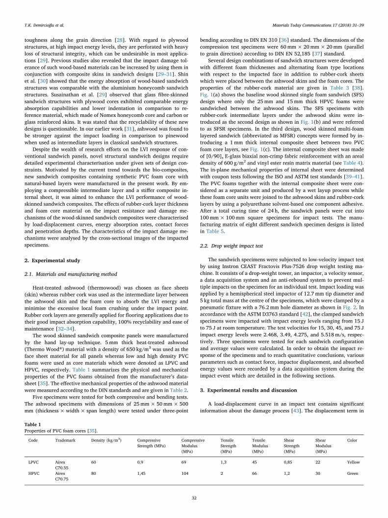
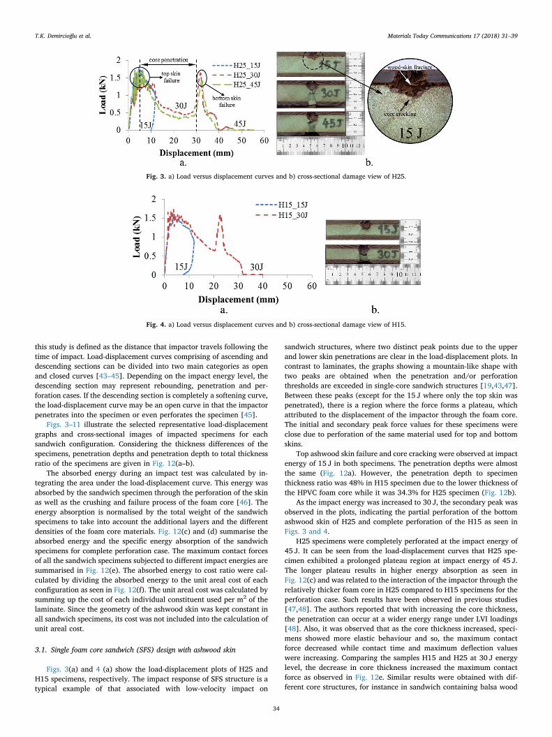
Figs. 3(a) and 4 (a) show the load-displacement plots of H25 andH15 specimens, respectively. The impact response of SFS structure is atypical example of that associated with low-velocity impact on
sandwich structures, where two distinct peak points due to the upperand lower skin penetrations are clear in the load-displacement plots. Incontrast to laminates, the graphs showing a mountain-like shape withtwo peaks are obtained when the penetration and/or perforationthresholds are exceeded in single-core sandwich structures [19,43,47].Between these peaks (except for the 15 J where only the top skin waspenetrated), there is a region where the force forms a plateau, whichattributed to the displacement of the impactor through the foam core.The initial and secondary peak force values for these specimens wereclose due to perforation of the same material used for top and bottomskins.
Top ashwood skin failure and core cracking were observed at impactenergy of 15 J in both specimens. The penetration depths were almostthe same (Fig. 12a). However, the penetration depth to specimenthickness ratio was 48% in H15 specimen due to the lower thickness ofthe HPVC foam core while it was 34.3% for H25 specimen (Fig. 12b).
As the impact energy was increased to 30 J, the secondary peak wasobserved in the plots, indicating the partial perforation of the bottomashwood skin of H25 and complete perforation of the H15 as seen inFigs. 3 and 4.
H25 specimens were completely perforated at the impact energy of45 J. It can be seen from the load-displacement curves that H25 spe-cimen exhibited a prolonged plateau region at impact energy of 45 J.The longer plateau results in higher energy absorption as seen inFig. 12(c) and was related to the interaction of the impactor through therelatively thicker foam core in H25 compared to H15 specimens for theperforation case. Such results have been observed in previous studies[47,48]. The authors reported that with increasing the core thickness,the penetration can occur at a wider energy range under LVI loadings[48]. Also, it was observed that as the core thickness increased, speci-mens showed more elastic behaviour and so, the maximum contactforce decreased while contact time and maximum deflection valueswere increasing. Comparing the samples H15 and H25 at 30 J energylevel, the decrease in core thickness increased the maximum contactforce as observed in Fig. 12e. Similar results were obtained with dif-ferent core structures, for instance in sandwich containing balsa wood
Fig. 3. a) Load versus displacement curves and b) cross-sectional damage view of H25.
Fig. 4. a) Load versus displacement curves and b) cross-sectional damage view of H15.
T.K. Demircioğlu et al. Materials Today Communications 17 (2018) 31–39
34
core, the increase in core thickness causes an increase in the perforationthreshold [47].
Although the H25 specimen was heavier, it absorbed higher specificenergy than the H15 specimen. Similar results were observed in anotherstudy [49]. Authors found that the increase in the foam core thicknesscould improve the specific energy absorption amount of the sameskinned sandwich composite under an impact event.
3.2. Single foam core sandwich design with rubber-cork intermediate layerand ashwood skin (SFSR)
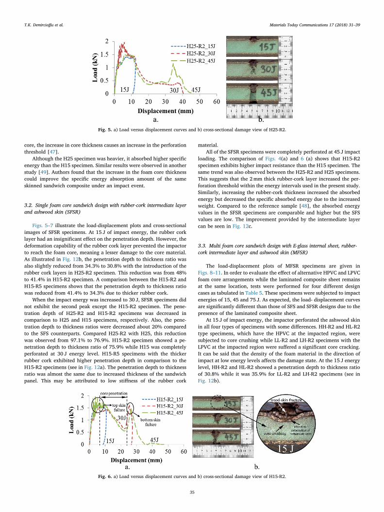
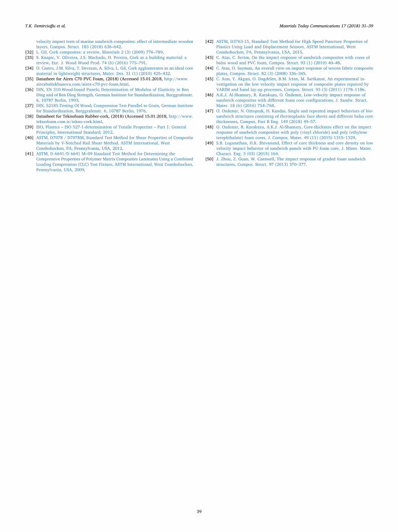
Figs. 5–7 illustrate the load-displacement plots and cross-sectionalimages of SFSR specimens. At 15 J of impact energy, the rubber corklayer had an insignificant effect on the penetration depth. However, thedeformation capability of the rubber cork layer prevented the impactorto reach the foam core, meaning a lesser damage to the core material.As illustrated in Fig. 12b, the penetration depth to thickness ratio wasalso slightly reduced from 34.3% to 30.8% with the introduction of therubber cork layers in H25-R2 specimen. This reduction was from 48%to 41.4% in H15-R2 specimen. A comparison between the H15-R2 andH15-R5 specimens shows that the penetration depth to thickness ratiowas reduced from 41.4% to 34.3% due to thicker rubber cork.
When the impact energy was increased to 30 J, SFSR specimens didnot exhibit the second peak except the H15-R2 specimen. The pene-tration depth of H25-R2 and H15-R2 specimens was decreased incomparison to H25 and H15 specimens, respectively. Also, the pene-tration depth to thickness ratios were decreased about 20% comparedto the SFS counterparts. Compared H25-R2 with H25, this reductionwas observed from 97.1% to 76.9%. H15-R2 specimen showed a pe-netration depth to thickness ratio of 75.9% while H15 was completelyperforated at 30 J energy level. H15-R5 specimens with the thickerrubber cork exhibited higher penetration depth in comparison to theH15-R2 specimens (see in Fig. 12a). The penetration depth to thicknessratio was almost the same due to increased thickness of the sandwichpanel. This may be attributed to low stiffness of the rubber cork
material.All of the SFSR specimens were completely perforated at 45 J impact
loading. The comparison of Figs. 4(a) and 6 (a) shows that H15-R2specimen exhibits higher impact resistance than the H15 specimen. Thesame trend was also observed between the H25-R2 and H25 specimens.This suggests that the 2mm thick rubber-cork layer increased the per-foration threshold within the energy intervals used in the present study.Similarly, increasing the rubber-cork thickness increased the absorbedenergy but decreased the specific absorbed energy due to the increasedweight. Compared to the reference sample [48], the absorbed energyvalues in the SFSR specimens are comparable and higher but the SFSvalues are low. The improvement provided by the intermediate layercan be seen in Fig. 12c.
3.3. Multi foam core sandwich design with E-glass internal sheet, rubber-cork intermediate layer and ashwood skin (MFSR)
The load-displacement plots of MFSR specimens are given inFigs. 8–11. In order to evaluate the effect of alternative HPVC and LPVCfoam core arrangements while the laminated composite sheet remainsat the same location, tests were performed for four different designcases as tabulated in Table 5. These specimens were subjected to impactenergies of 15, 45 and 75 J. As expected, the load- displacement curvesare significantly different than those of SFS and SFSR designs due to thepresence of the laminated composite sheet.
At 15 J of impact energy, the impactor perforated the ashwood skinin all four types of specimens with some differences. HH-R2 and HL-R2type specimens, which have the HPVC at the impacted region, weresubjected to core crushing while LL-R2 and LH-R2 specimens with theLPVC at the impacted region were suffered a significant core cracking.It can be said that the density of the foam material in the direction ofimpact at low energy levels affects the damage state. At the 15 J energylevel, HH-R2 and HL-R2 showed a penetration depth to thickness ratioof 30.8% while it was 35.9% for LL-R2 and LH-R2 specimens (see inFig. 12b).
Fig. 5. a) Load versus displacement curves and b) cross-sectional damage view of H25-R2.
Fig. 6. a) Load versus displacement curves and b) cross-sectional damage view of H15-R2.
T.K. Demircioğlu et al. Materials Today Communications 17 (2018) 31–39
35

In the case of 45 J of impact energy, the impactor contacts with theE-glass internal sheet and reveals a force peak in the load-displacementcurves (see Figs. 8–11). This interaction caused a fibre breakage andinter-laminar delamination in the E-glass sheet. Although the impactordid not get into contact with the lower core, it was crushed due to the
load transferred through the internal sheet. The delamination widthwere determined by measuring over the damaged specimens by a ver-nier caliper. It is also seen from the Figs. 8 and 9 that the extent ofdelamination are was reduced by introducing HPVC foam core foam onthe sides of the internal sheet (Fig. 8b). The higher deformation
Fig. 7. a) Load versus displacement curves and b) cross-sectional damage view of H15-R5.
Fig. 8. a) Load versus displacement curves and b) cross-sectional damage view of HH-R2.
Fig. 9. a) Load versus displacement curves and b) cross-sectional damage view of LL-R2.
Fig. 10. a) Load versus displacement curves and b) cross-sectional damage view of HL-R2.
T.K. Demircioğlu et al. Materials Today Communications 17 (2018) 31–39
36

capability of LPVC foam caused a larger delamination area due tostiffness incompatibility (Fig. 9b). At 45 J energy level, the delamina-tion width at LL-R2 specimen was about 60mm while it was around40mm at HH-R2 specimen. In the HL-R2 and LH-R2 specimens, theinternal sheet was broken at this energy level (Figs. 10b and 11 b). Atthis energy level, the LL-R2 samples showed a 69.2% penetration depthto thickness value, while the others remained at the same level of 64.1%(see, Fig. 12b).
For the impact energy of 75 J, all curves are in an open form cor-responding to a full perforation case in which all the ashwood skins,
internal composite sheet and the core material were perforated. At thisenergy level, it is clear that the first, second and third peaks representfailure in the upper ashwood skin, internal composite sheet and lowerashwood skin, respectively. LL-R2 specimens experienced the lowestenergy absorption because of the low density PVC core material. Incontrast, HH-R2 comprising of the high density PVC resulted highestabsorbed energy (see Fig. 12 (c)). This confirms the earlier result, whichindicates that stiffer foam core material in the entire thickness of thecore reduces the impact induced damage of multilayered sandwichpanels [25,26]. Compared the absorbed energy values of HL-R2 and LH-
Fig. 11. a) Load versus displacement curves and b) cross-sectional damage view of LH-R2.
Fig. 12. LVI test results; a) penetration depth, b) penetration depth/specimen thickness, c) absorbed energy, d) specific absorbed energy, e) maximum contact forceand f) absorbed energy/cost.
T.K. Demircioğlu et al. Materials Today Communications 17 (2018) 31–39
37

R2, placing the higher density foam uppermost resulted in a slight in-crease in the perforation resistance (see in Figs. 12c). Such results wereobserved in the impact response of the graded foam sandwich con-structions [50]. The cross-sectional views of the MFSR specimens re-vealed that using a high density PVC foam core created a more impact-resistant structure under LVI loading.
4. Conclusions
Industrial woods inherently fail in a brittle manner which makesthem susceptible to impact loadings. Despite this weakness, they areconsidered as eco-friendly materials due to their recyclability and al-ternative structural configurations have been evaluated in order to in-crease their impact resistance.
In the present paper, innovative, eco-friendly and impact resistantsandwich structure designs were developed using recyclable and long-lasting thermowood and rubber-cork materials. Three different con-cepts were presented in order to evaluate their performance under lowvelocity impact loading. Cross-sectional images of the damaged speci-mens enabled visual inspection of interior damage patterns and pene-tration depth values. As a result, this research shed light on the LVIbehavior of environmentally friendly wood-skinned sandwich compo-sites. The results can be used to improve the LVI damage tolerance ofcommercial available PVC core wood marine sandwich panels.Fundamental findings are summarised below:
• The absorbed energy values were obtained from the test data andrepresent the area under the load-displacement graphs. For the 15 Jof impact energy, the upper skin was perforated and absorbed34.8% of the impact energy while 59.2% of that was absorbed by thefoam core and/or the rubber cork damage depending on the struc-ture. At 12mm final penetration, 94% of impact energy was ab-sorbed and 6% was spent as rebounding case.
• Introduction of the rubber cork intermediate layer resulted in re-duced penetration depth for 30 J of impact energy by increasing theenergy absorption. At low level of impact energy, the rubber corkprevented foam cracking, and the damage was therefore confined tothe recyclable materials only. This is an advantage for the repairprocesses and to avoid the progressive cracking of the foam uponfurther loading cycles.
• Penetration depth was increased with increasing the rubber corkthickness due to the replacement of stiff foam core by a relativelyflexible rubber cork material on the travel path of the impactor.However, the absorbed energy was increased about 10% while thespecific absorbed energy decreased due to weight gain of thesandwich structure.
• The maximum contact force values were between 1.5 and 2 kN forSFS and SFSR structures. In MFSR structures it was raised up to4.5 kN due to introduction of high stiffness E-glass internal com-posite layer. The higher contact force was resulted in higher per-foration threshold and absorbed energy. For the non-perforatingenergy levels, high density foam core at the impacted side of theMFSR design may be used to considerably lighten the structure.
• From the economical perspective of view, with respect to the spe-cific absorbed energy and absorbed energy/cost ratios, HH-R2 wasfound to be the best panel configuration among the proposed designalternatives.
• The introduction of the rubber-cork material increased the recycl-ability rate of the sandwich structures up to 57%. In the MFSRconfigurations, the recyclability rate is 35.6%.
The proposed wood skinned sandwich composite designs are easy tomanufacture, repair and recycle in addition to their valuable estheticalappearance. These configurations may be utilised in floor applicationssuch as decks and cabins, bulkhead panels as well as interior and ex-terior design applications.
Acknowledgements
The authors are grateful to Dr Okan Özdemir and ProfessorRamazan Karakuzu of Dokuz Eylül University for useful discussions.
References
[1] M. Matos, M. Simplicio, Innovation and sustainability in mechanical design throughmaterials selection, Mater. Des. 27 (1) (2006) 74–78.
[2] Ma.D. Bovea, R. Vidal, Materials selection for sustainable product design: a casestudy of wood based furniture eco-design, Mater. Des. 25 (2) (2004) 111–116.
[3] S.J. Pickering, Recycling technologies for thermoset composite materials—currentstatus, Compos. Part A Appl. Sci. Manuf. 37 (8) (2006) 1206–1215.
[4] V. Bucci, P. Corigliano, V. Crupi, G. Epasto, E. Guglielmino, A. Marinò,Experimental investigation on Iroko wood used in shipbuilding, Proc. Inst. Mech.Eng. Part C J. Mech. Eng. Sci. 231 (1) (2017) 128–139.
[5] S. Abrate, B. Castanié, Y.D. Rajapakse, Dynamic Failure of Composite and SandwichStructures, Springer Science & Business Media, 2012.
[6] F. Negro, C. Cremonini, R. Zanuttini, M. Properzi, F. Pichelin, A new wood-basedlightweight composite for boatbuilding, Wood Res. 56 (2) (2011) 257–266.
[7] C. Cremonini, F. Negro, M. Properzi, R. Zanuttini, Wood-based composites inmarine craft: the state of the art in Italy, COST E49 conference: lightweight wood-base composites, Production, Properties and Usage, Bled, 23rd-25th June, (2008),pp. 15–33.
[8] J. Susainathan, F. Eyma, E. De Luycker, A. Cantarel, B. Castanie, Manufacturing andquasi-static bending behavior of wood-based sandwich structures, Compos. Struct.182 (2017) 487–504.
[9] N. Lakreb, B. Bezzazi, H. Pereira, Mechanical behavior of multilayered sandwichpanels of wood veneer and a core of cork agglomerates, Mater. Des. 65 (2015)627–636 1980-2015.
[10] N. Lakreb, S. Knapic, J.S. Machado, B. Bezzazi, H. Pereira, Properties of multi-layered sandwich panels with an agglomerated cork core for interior applications inbuildings, Eur. J. Wood Wood Prod. (2017) 1–11.
[11] Y. Qi, H. Fang, H. Shi, W. Liu, Y. Qi, Y. Bai, Bending performance of GFRP-woodsandwich beams with lattice-web reinforcement in flatwise and sidewise directions,Constr. Build. Mater. 156 (2017) 532–545.
[12] F. Zhang, W. Liu, L. Wang, Y. Qi, D. Zhou, H. Fang, Flexural behavior of hybridcomposite beams with a bamboo layer and lattice ribs, J. Reinforced Plastics andCompos. 34 (7) (2015) 521–533.
[13] L. Sutherland, A review of impact testing on marine composite materials: partI–marine impacts on marine composites, Compos. Struct. 188 (2017) 197–208.
[14] L. Sutherland, A review of impact testing on marine composite materials, Part III:damage tolerance and durability, Compos. Struct. 188 (2018) 512–518.
[15] S. Abrate, Impact Engineering of Composite Structures, Springer Science & BusinessMedia, 2011.
[16] M.A. Hazizan, W. Cantwell, The low velocity impact response of foam-basedsandwich structures, Compos. Part B Eng. 33 (3) (2002) 193–204.
[17] T. Anderson, E. Madenci, Experimental investigation of low-velocity impact char-acteristics of sandwich composites, Compos. Struct. 50 (3) (2000) 239–247.
[18] J. Wang, A.M. Waas, H. Wang, Experimental and numerical study on the low-ve-locity impact behavior of foam-core sandwich panels, Compos. Struct. 96 (2013)298–311.
[19] C. Atas, U. Potoğlu, The effect of face-sheet thickness on low-velocity impact re-sponse of sandwich composites with foam cores, J. Sandw. Struct. Mater. 18 (2)(2016) 215–228.
[20] A. Mamalis, K. Spentzas, N. Pantelelis, D. Manolakos, M. Ioannidis, A new hybridconcept for sandwich structures, Compos. Struct. 83 (4) (2008) 335–340.
[21] A.P. Suvorov, G.J. Dvorak, Enhancement of low velocity impact damage resistanceof sandwich plates, Int. J. Solids Struct. 42 (8) (2005) 2323–2344.
[22] G.J. Dvorak, A.P. Suvorov, Protection of sandwich plates from low-velocity impact,J. Compos. Mater. 40 (15) (2006) 1317–1331.
[23] S.A. Sabah, A. Kueh, M. Al-Fasih, Bio-inspired vs. conventional sandwich beams: alow-velocity repeated impact behavior exploration, Constr. Build. Mater. 169(2018) 193–204.
[24] S.A. Sabah, A. Kueh, M. Al-Fasih, Comparative low-velocity impact behavior of bio-inspired and conventional sandwich composite beams, Compos. Sci. Technol. 149(2017) 64–74.
[25] S. Jedari Salami, M. Sadighi, M. Shakeri, M. Moeinfar, An investigation on lowvelocity impact response of multilayer sandwich composite structures, Sci. World J.(2013) 2013.
[26] D. Jiang, D. Shu, Local displacement of core in two-layer sandwich compositestructures subjected to low velocity impact, Compos. Struct. 71 (1) (2005) 53–60.
[27] M. Hildebrand, Local Impact Strength of Various Boat-building Materials, TechnicalResearch Centre of Finland, 1997.
[28] I. Daniel, J. Abot, P. Schubel, J.-J. Luo, Response and damage tolerance of com-posite sandwich structures under low velocity impact, Exp. Mech. 52 (1) (2012)37–47.
[29] J. Susainathan, F. Eyma, E. De Luycker, A. Cantarel, B. Castanie, Experimental in-vestigation of impact behavior of wood-based sandwich structures, Compos. Part AAppl. Sci. Manuf. (2018).
[30] K.B. Shin, J.Y. Lee, S.H. Cho, An experimental study of low-velocity impact re-sponses of sandwich panels for Korean low floor bus, Compos. Struct. 84 (3) (2008)228–240.
[31] F. Balıkoğlu, T. Demircioğlu, O. İnal, N. Arslan, A. Ataş, Compression after low
T.K. Demircioğlu et al. Materials Today Communications 17 (2018) 31–39
38
velocity impact tests of marine sandwich composites: effect of intermediate woodenlayers, Compos. Struct. 183 (2018) 636–642.
[32] L. Gil, Cork composites: a review, Materials 2 (3) (2009) 776–789.[33] S. Knapic, V. Oliveira, J.S. Machado, H. Pereira, Cork as a building material: a
review, Eur. J. Wood Wood Prod. 74 (6) (2016) 775–791.[34] O. Castro, J.M. Silva, T. Devezas, A. Silva, L. Gil, Cork agglomerates as an ideal core
material in lightweight structures, Mater. Des. 31 (1) (2010) 425–432.[35] Datasheet for Airex C70 PVC Foam, (2018) (Accessed 15.01.2018, http://www.
airexbaltekbanova.com/airex-c70-pvc-foam.html.[36] DIN, EN 310-Wood-based Panels; Determination of Modulus of Elasticity in Ben
Ding and of Ben Ding Strength, German Institute for Standardization, Burggrafenstr.6, 10787 Berlin, 1993.
[37] DIN, 52185-Testing Of Wood; Compression Test Parallel to Grain, German Institutefor Standardization, Burggrafenstr. 6, 10787 Berlin, 1976.
[38] Datasheet for Teknofoam Rubber-cork, (2018) (Accessed 15.01.2018, http://www.teknofoam.com.tr/tekno-cork.html.
[39] ISO, Plastics – ISO 527-1-determination of Tensile Properties – Part 1: GeneralPrinciples, International Standard, 2012.
[40] ASTM, D7078 / D7078M, Standard Test Method for Shear Properties of CompositeMaterials by V-Notched Rail Shear Method, ASTM International, WestConshohocken, PA, Pennsylvania, USA, 2012.
[41] ASTM, D 6641/D 6641 M–09 Standard Test Method for Determining theCompressive Properties of Polymer Matrix Composites Laminates Using a CombinedLoading Compression (CLC) Test Fixture, ASTM International, West Conshohocken,Pennsylvania, USA, 2009.
[42] ASTM, D3763-15, Standard Test Method for High Speed Puncture Properties ofPlastics Using Load and Displacement Sensors, ASTM International, WestConshohocken, PA, Pennsylvania, USA, 2015.
[43] C. Atas, C. Sevim, On the impact response of sandwich composites with cores ofbalsa wood and PVC foam, Compos. Struct. 93 (1) (2010) 40–48.
[44] C. Atas, O. Sayman, An overall view on impact response of woven fabric compositeplates, Compos. Struct. 82 (3) (2008) 336–345.
[45] C. Atas, Y. Akgun, O. Dagdelen, B.M. Icten, M. Sarikanat, An experimental in-vestigation on the low velocity impact response of composite plates repaired byVARIM and hand lay-up processes, Compos. Struct. 93 (3) (2011) 1178–1186.
[46] A.K.J. Al-Shamary, R. Karakuzu, O. Özdemir, Low-velocity impact response ofsandwich composites with different foam core configurations, J. Sandw. Struct.Mater. 18 (6) (2016) 754–768.
[47] O. Ozdemir, N. Oztoprak, H. Kandas, Single and repeated impact behaviors of bio-sandwich structures consisting of thermoplastic face sheets and different balsa corethicknesses, Compos. Part B Eng. 149 (2018) 49–57.
[48] O. Ozdemir, R. Karakuzu, A.K.J. Al-Shamary, Core-thickness effect on the impactresponse of sandwich composites with poly (vinyl chloride) and poly (ethyleneterephthalate) foam cores, J. Compos. Mater. 49 (11) (2015) 1315–1329.
[49] S.B. Loganathan, H.K. Shivanand, Effect of core thickness and core density on lowvelocity impact behavior of sandwich panels with PU foam core, J. Miner. Mater.Charact. Eng. 3 (03) (2015) 164.
[50] J. Zhou, Z. Guan, W. Cantwell, The impact response of graded foam sandwichstructures, Compos. Struct. 97 (2013) 370–377.
T.K. Demircioğlu et al. Materials Today Communications 17 (2018) 31–39
39