Embed Size (px)
Citation preview
Materials Science and Engineering C 57 (2015) 58–66
Contents lists available at ScienceDirect
Materials Science and Engineering C
j ourna l homepage: www.e lsev ie r .com/ locate /msec
Enhancement of bioactivity on medical polymer surface using highpower impulse magnetron sputtered titanium dioxide film
Yi-Ju Yang a,1, Hsi-Kai Tsou b,c,1, Ying-Hung Chen a, Chi-Jen Chung d,⁎, Ju-Liang He a
a Department of Materials Science and Engineering, Feng Chia University, No. 100, Wenhwa Road, Seatwen District, Taichung City 40724, Taiwanb Functional Neurosurgery Division, Neurological Institute, Taichung Veterans General Hospital, No. 1650, Sec. 4, Taiwan Boulevard, Seatwen District, Taichung City 40705, Taiwanc Department of Rehabilitation, Jen-Teh Junior College of Medicine, Nursing and Management, No. 79-9, Sha-Luen Hu, Hou-Loung Town, Miaoli County 35664,Taiwand Department of Dental Technology and Materials Science, Central Taiwan University of Science and Technology, No. 666, Buzih Road, Beitun District, Taichung City 40601, Taiwan
⁎ Corresponding author.E-mail address: [email protected] (C.-J. Chung).
1 Yi-Ju Yang and Hsi-Kai Tsou share equal contributionThese authors contributed to the work equally and should
http://dx.doi.org/10.1016/j.msec.2015.07.0390928-4931/© 2015 Elsevier B.V. All rights reserved.
a b s t r a c t
a r t i c l e i n f oArticle history:Received 22 February 2015Received in revised form 9 July 2015Accepted 22 July 2015Available online 23 July 2015
Keywords:Polyetheretherketone (PEEK)Titanium dioxide (TiO2)High power impulse magnetron sputtering(HIPIMS)Film adhesionOsteoblast compatibility
This study utilizes a novel technique, high power impulse magnetron sputtering (HIPIMS), which provides ahigher ionization rate and ion bombardment energy than direct currentmagnetron sputtering (DCMS), to depos-it high osteoblast compatible titanium dioxide (TiO2) coatings with anatase (A-TiO2) and rutile (R-TiO2) phasesonto the biomedical polyetheretherketone (PEEK) polymer substrates at low temperature. The adhesions of TiO2
coatings that were fabricated using HIPIMS and DCMS were compared. The in vitro biocompatibility of thesecoatings was confirmed.The results reveal that HIPIMS can be used to prepare crystallinic columnar A-TiO2 and R-TiO2 coatings on PEEKsubstrate if the ratio of oxygen to argon is properly controlled. According to a tape adhesion test, the HIPIMS-TiO2
coatings had an adhesion grade of 5B even after theywere immersed in simulated body fluid (SBF) environmentsfor 28 days. Scratch tests proved that HIPIMS-TiO2 coatings undergo cohesive failure. These results demonstratethat the adhesive force between HIPIMS-TiO2 coating/PEEK is stronger than that between DCMS-TiO2 coating/PEEK. After a long period (28 days) of immersion in SBF, a bone-like crystallinic hydroxyapatite layer with a cor-responding Ca/P stoichiometry was formed on both HIPIMS-TiO2. The osteoblast compatibility of HIPIMS-TiO2
exceeded that of the bare PEEK substrate. It is also noticeable that the R-TiO2 performed better in vitro thanthe A-TiO2 due to the formation of many negatively charged hydroxyl groups (−OH−) groups on R-TiO2 (110)surface. In summary, the HIPIMS-TiO2 coatings satisfied the requirements for osseointegration, suggesting thepossibility of using HIPIMS to modify the PEEK surface with TiO2 for spinal implants.
© 2015 Elsevier B.V. All rights reserved.
1. Introduction
In themost serious cases of damage to, or weakening of, the annulusfibrosus by a sudden force or with increasing age, resulting in the bulg-ing out or even the posterior extrusion of the nucleus pulposus, spinalfusion surgery is commonly necessary. Surgeons perform discectomysurgery to remove the intervertebral disc and then implant a new boneor artificial implant material to support the upper and lower spinal ver-tebrae. In recent years, the most commonly used material as an artificialspinal fusion cage to promote spinal healing is polyetheretherketone(PEEK) polymer [1], mainly because its elastic modulus is similar tothat of human cancellous bone, so the stress shield effect is avoided [2].Furthermore, PEEK materials are also radiolucent to X-rays and donot cause a medical image shielding problem [2]. However, PEEK is
.be regarded as co-first authors.
hydrophobic [3] and bioinert [4] material, attaching poorly to osteo-blasts, subsequently exhibiting slow osseointegration, resulting in along postoperative recovery time with a high risk for pseudarthrosisbetween vertebrae and the cage. Therefore, various modification tech-niques, particularly the surfacemodification, for PEEK have been devel-oped to enhance biological characteristics, such as deposition ofhydroxyapatite (HAp) [5,6] or Ti film [7] using a range of coatingmethods, functionalization of hydroxyl groups (−OH−) using NaOHsolution treatment [8], or grafting of carboxyl groups using plasmapolymerization of acrylic acid [9].
Ti and its alloy (such as Ti-6Al-4 V) have been extensively recog-nized as preferredmaterials for bone replacement owing to its sufficientmechanical strength andbiocompatibilitywith the human body [10,11].The surface oxide layer of titanium dioxide (TiO2) contributes to thisbiocompatibility as it interacts with proteins in the surrounding physio-logical environment [12]. Empirical evidence has established that thesurface of TiO2 generates negatively charged −OH− in a humid envi-ronment, and then binds with Ca2+, PO4
3− and protein to form bone-like apatite [12,13]. This apatite provides a favorable environment for
59Y.-J. Yang et al. / Materials Science and Engineering C 57 (2015) 58–66
cell adhesion and growth. Moreover, according to animal experiments,TiO2 has an excellent osseointegration capacity [14,15]. Some scholarshave classified TiO2 as a bioactive material [16].
The emerging method of magnetron sputtering involves effectivecontrol of the delivery of power to the target by high power impulsemagnetron sputtering (HIPIMS) [17], in which a high-density plasmais generated by a power source and a high voltage pulse at peakpower for a very short period causes a high degree of ionization of thesputtered species. This process enables HIPIMS to provide a high plasmadensity, enabling a high-quality and strongly adheringfilm to be formedat a relatively low substrate temperature.
Based on our best knowledge, our group first proposed the surfacemodification on PEEK polymer using TiO2 coating by arc ion plating(AIP). The effect of TiO2 phase structure on biomimetic hydroxyapatite(HAp) growth behavior and osteoblast compatibility are then elucidat-ed comprehensively, demonstrating AIP-TiO2 coating significantly im-proves the in vitro characteristics of PEEK [18,19]. In this study, theHIPIMS system is used to prepare a strongly adhesive and highlyosteoblast-compatible TiO2 coating on bioinert PEEK substrate to pro-mote the growth of bone tissue on biomedical PEEK implant material.TiO2 coatings with the anatase (A-TiO2) and rutile (R-TiO2) phases areexamined. The microstructures and adhesions of HIPIMS-TiO2-coatedPEEK specimens are compared with those of direct current magnetronsputtered (DCMS)-TiO2-coated PEEK specimens.
2. Materials and methods
2.1. Preparation of TiO2 coating on PEEK substrate
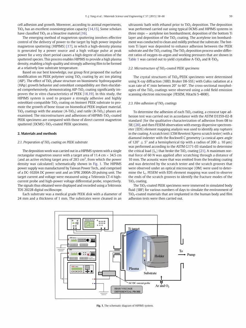
The depositionworkwas carried out in aHIPIMS systemwith a singlerectangular magnetron source with a target area of 11.4 cm × 34.5 cm(and an active etching target area of 283 cm2, from which the powerdensity was calculated) schematically shown in Fig. 1. The HIPIMSpower supply wasmanufactured by Taiwan Power Tech., and comprisedof a DC-1020A DC power unit and an SPIK 2000A-20 pulsing unit. Thetarget current and voltage were measured using a Tektronix CT-4 high-current probe and high-power voltage differential probe, respectively.The signals thus obtainedwere displayed and recorded using a TektronixTDS 2022B digital oscilloscope.
Each substrate was a medical grade PEEK disk with a diameter of24 mm and a thickness of 1 mm. The substrates were cleaned in an
Fig. 1. The schematic diagr
ultrasonic bath with ethanol prior to TiO2 deposition. The depositionwas performed carried out using typical DCMS and HIPIMS systems inthree steps— acetylene ion bombardment, deposition of the bottom Tilayer and deposition of the TiO2 coating. The acetylene ion bombard-mentwas conducted to clean andmildly preheat the substrate. The bot-tom Ti layer was deposited to enhance adhesion between the PEEKsubstrate and the TiO2 coating. The TiO2 deposition process under differ-ent ratios of oxygen-to-argon and working pressures that are shown inTable 1 was carried out to yield crystalline A-TiO2 and R-TiO2.
2.2. Microstructure of TiO2-coated PEEK specimens
The crystal structures of TiO2/PEEK specimens were determinedusing X-ray diffraction (XRD, Bruker D8-SSS) with CuKα radiation at ascan rate of 4°/min between 20° to 60°. The cross-sectional morphol-ogies of the TiO2 coatings were observed using a cold field emissionscanning electron microscope (FESEM, Hitachi S-4800).
2.3. Film adhesion of TiO2 coatings
To determine the adhesion of each TiO2 coating, a crosscut tape ad-hesion test was carried out in accordance with the ASTM D3359-02-Bstandard (for the qualitative characterization of adhesion from 0B to5B) [20], and then FESEMobservationwith energy dispersive spectrom-eter (EDS) element mapping analysis was used to identify any rupturesin the coating. A scratch test (CSMRevetest Xpress scratch tester)with adiamond indenter with the Rockwell C geometry (a conical apex angleof 120° ± 5° and a hemispherical tip with a radius of 200 ± 10 μm)was performed according to the ASTM G171-03 standard to determinethe critical load (Lc) that broke the TiO2 coating [21]. A maximum nor-mal force of 60 N was applied after scratching through a distance of10 mm. The acoustic wave that was emitted from the breaking coatingand was detected by the scratch tester and the scratch grooves thatwere observed under an optical microscope (OM) were used to deter-mine the Lc. FESEM with EDS element mapping was used to observethe ends of the scratch grooves to identify the fracture modes of theTiO2 coating.
The TiO2-coated PEEK specimens were immersed in simulated bodyfluid (SBF) for various numbers of days to simulate the environment ofTiO2-coated materials that are implanted in the human body and filmadhesion tests were then carried out.
am of HIPIMS system.
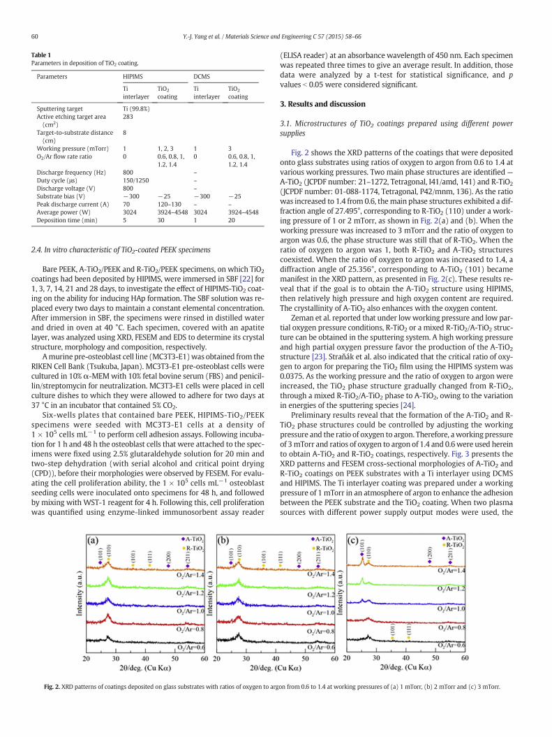
Table 1Parameters in deposition of TiO2 coating.
Parameters HIPIMS DCMS
Tiinterlayer
TiO2
coatingTiinterlayer
TiO2
coating
Sputtering target Ti (99.8%)Active etching target area(cm2)
283
Target-to-substrate distance(cm)
8
Working pressure (mTorr) 1 1, 2, 3 1 3O2/Ar flow rate ratio 0 0.6, 0.8, 1,
1.2, 1.40 0.6, 0.8, 1,
1.2, 1.4Discharge frequency (Hz) 800 –Duty cycle (μs) 150/1250 –Discharge voltage (V) 800 –Substrate bias (V) −300 −25 −300 −25Peak discharge current (A) 70 120–130 – –Average power (W) 3024 3924–4548 3024 3924–4548Deposition time (min) 5 30 1 20
60 Y.-J. Yang et al. / Materials Science and Engineering C 57 (2015) 58–66
2.4. In vitro characteristic of TiO2-coated PEEK specimens
Bare PEEK, A-TiO2/PEEK and R-TiO2/PEEK specimens, on which TiO2
coatings had been deposited by HIPIMS, were immersed in SBF [22] for1, 3, 7, 14, 21 and 28 days, to investigate the effect of HIPIMS-TiO2 coat-ing on the ability for inducing HAp formation. The SBF solution was re-placed every two days to maintain a constant elemental concentration.After immersion in SBF, the specimens were rinsed in distilled waterand dried in oven at 40 °C. Each specimen, covered with an apatitelayer, was analyzed using XRD, FESEM and EDS to determine its crystalstructure, morphology and composition, respectively.
Amurine pre-osteoblast cell line (MC3T3-E1)was obtained from theRIKEN Cell Bank (Tsukuba, Japan). MC3T3-E1 pre-osteoblast cells werecultured in 10% α-MEMwith 10% fetal bovine serum (FBS) and penicil-lin/streptomycin for neutralization. MC3T3-E1 cells were placed in cellculture dishes to which they were allowed to adhere for two days at37 °C in an incubator that contained 5% CO2.
Six-wells plates that contained bare PEEK, HIPIMS-TiO2/PEEKspecimens were seeded with MC3T3-E1 cells at a density of1 × 105 cells mL−1 to perform cell adhesion assays. Following incuba-tion for 1 h and 48 h the osteoblast cells that were attached to the spec-imens were fixed using 2.5% glutaraldehyde solution for 20 min andtwo-step dehydration (with serial alcohol and critical point drying(CPD)), before their morphologies were observed by FESEM. For evalu-ating the cell proliferation ability, the 1 × 10⁵ cells mL−1 osteoblastseeding cells were inoculated onto specimens for 48 h, and followedby mixing with WST-1 reagent for 4 h. Following this, cell proliferationwas quantified using enzyme-linked immunosorbent assay reader
Fig. 2. XRD patterns of coatings deposited on glass substrates with ratios of oxygen to arg
(ELISA reader) at an absorbance wavelength of 450 nm. Each specimenwas repeated three times to give an average result. In addition, thosedata were analyzed by a t-test for statistical significance, and pvalues b 0.05 were considered significant.
3. Results and discussion
3.1. Microstructures of TiO2 coatings prepared using different powersupplies
Fig. 2 shows the XRD patterns of the coatings that were depositedonto glass substrates using ratios of oxygen to argon from 0.6 to 1.4 atvarious working pressures. Two main phase structures are identified—A-TiO2 (JCPDF number: 21–1272, Tetragonal, I41/amd, 141) and R-TiO2
(JCPDF number: 01-088-1174, Tetragonal, P42/mnm, 136). As the ratiowas increased to 1.4 from 0.6, themain phase structures exhibited a dif-fraction angle of 27.495°, corresponding to R-TiO2 (110) under a work-ing pressure of 1 or 2 mTorr, as shown in Fig. 2(a) and (b). When theworking pressure was increased to 3 mTorr and the ratio of oxygen toargon was 0.6, the phase structure was still that of R-TiO2. When theratio of oxygen to argon was 1, both R-TiO2 and A-TiO2 structurescoexisted. When the ratio of oxygen to argon was increased to 1.4, adiffraction angle of 25.356°, corresponding to A-TiO2 (101) becamemanifest in the XRD pattern, as presented in Fig. 2(c). These results re-veal that if the goal is to obtain the A-TiO2 structure using HIPIMS,then relatively high pressure and high oxygen content are required.The crystallinity of A-TiO2 also enhances with the oxygen content.
Zeman et al. reported that under lowworking pressure and low par-tial oxygen pressure conditions, R-TiO2 or a mixed R-TiO2/A-TiO2 struc-ture can be obtained in the sputtering system. A high working pressureand high partial oxygen pressure favor the production of the A-TiO2
structure [23]. Straňák et al. also indicated that the critical ratio of oxy-gen to argon for preparing the TiO2 film using the HIPIMS system was0.0375. As the working pressure and the ratio of oxygen to argon wereincreased, the TiO2 phase structure gradually changed from R-TiO2,through a mixed R-TiO2/A-TiO2 phase to A-TiO2, owing to the variationin energies of the sputtering species [24].
Preliminary results reveal that the formation of the A-TiO2 and R-TiO2 phase structures could be controlled by adjusting the workingpressure and the ratio of oxygen to argon. Therefore, aworking pressureof 3mTorr and ratios of oxygen to argon of 1.4 and 0.6were used hereinto obtain A-TiO2 and R-TiO2 coatings, respectively. Fig. 3 presents theXRD patterns and FESEM cross-sectional morphologies of A-TiO2 andR-TiO2 coatings on PEEK substrates with a Ti interlayer using DCMSand HIPIMS. The Ti interlayer coating was prepared under a workingpressure of 1 mTorr in an atmosphere of argon to enhance the adhesionbetween the PEEK substrate and the TiO2 coating. When two plasmasources with different power supply output modes were used, the
on from 0.6 to 1.4 at working pressures of (a) 1 mTorr, (b) 2 mTorr and (c) 3 mTorr.
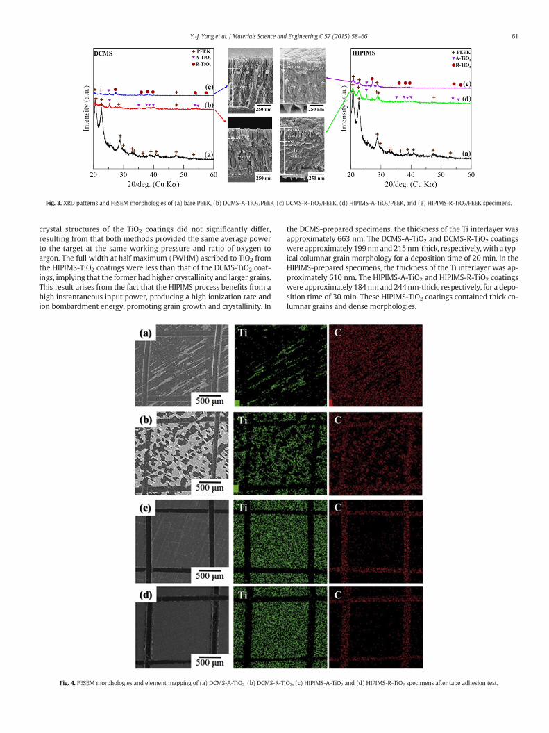
Fig. 3. XRD patterns and FESEM morphologies of (a) bare PEEK, (b) DCMS-A-TiO2/PEEK, (c) DCMS-R-TiO2/PEEK, (d) HIPIMS-A-TiO2/PEEK, and (e) HIPIMS-R-TiO2/PEEK specimens.
61Y.-J. Yang et al. / Materials Science and Engineering C 57 (2015) 58–66
crystal structures of the TiO2 coatings did not significantly differ,resulting from that both methods provided the same average powerto the target at the same working pressure and ratio of oxygen toargon. The full width at half maximum (FWHM) ascribed to TiO2 fromthe HIPIMS-TiO2 coatings were less than that of the DCMS-TiO2 coat-ings, implying that the former had higher crystallinity and larger grains.This result arises from the fact that the HIPIMS process benefits from ahigh instantaneous input power, producing a high ionization rate andion bombardment energy, promoting grain growth and crystallinity. In
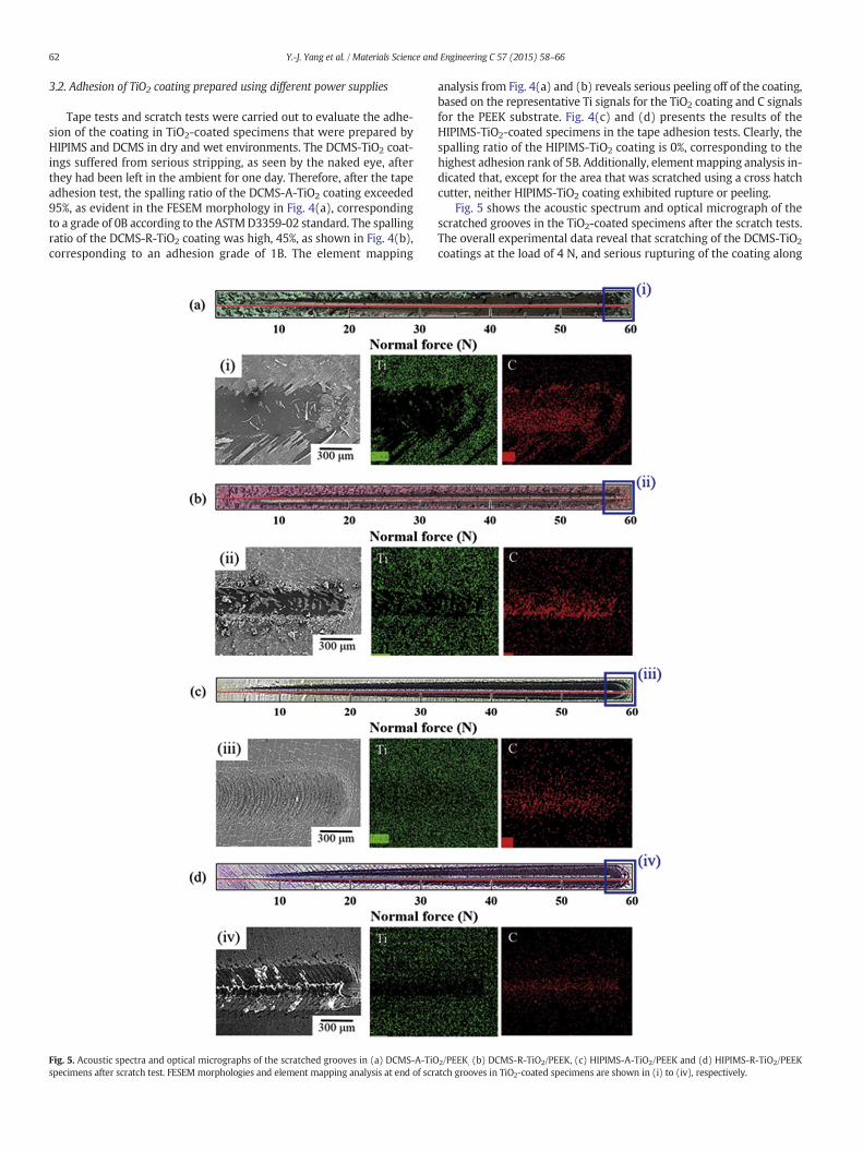
Fig. 4. FESEM morphologies and element mapping of (a) DCMS-A-TiO2, (b) DCMS-R-Ti
the DCMS-prepared specimens, the thickness of the Ti interlayer wasapproximately 663 nm. The DCMS-A-TiO2 and DCMS-R-TiO2 coatingswere approximately 199nmand 215 nm-thick, respectively, with a typ-ical columnar grain morphology for a deposition time of 20 min. In theHIPIMS-prepared specimens, the thickness of the Ti interlayer was ap-proximately 610 nm. The HIPIMS-A-TiO2 and HIPIMS-R-TiO2 coatingswere approximately 184 nmand 244 nm-thick, respectively, for a depo-sition time of 30 min. These HIPIMS-TiO2 coatings contained thick co-lumnar grains and dense morphologies.
O2, (c) HIPIMS-A-TiO2 and (d) HIPIMS-R-TiO2 specimens after tape adhesion test.
62 Y.-J. Yang et al. / Materials Science and Engineering C 57 (2015) 58–66
3.2. Adhesion of TiO2 coating prepared using different power supplies
Tape tests and scratch tests were carried out to evaluate the adhe-sion of the coating in TiO2-coated specimens that were prepared byHIPIMS and DCMS in dry and wet environments. The DCMS-TiO2 coat-ings suffered from serious stripping, as seen by the naked eye, afterthey had been left in the ambient for one day. Therefore, after the tapeadhesion test, the spalling ratio of the DCMS-A-TiO2 coating exceeded95%, as evident in the FESEM morphology in Fig. 4(a), correspondingto a grade of 0B according to the ASTMD3359-02 standard. The spallingratio of the DCMS-R-TiO2 coating was high, 45%, as shown in Fig. 4(b),corresponding to an adhesion grade of 1B. The element mapping
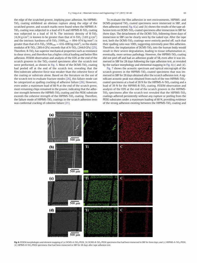
Fig. 5. Acoustic spectra and optical micrographs of the scratched grooves in (a) DCMS-A-TiOspecimens after scratch test. FESEM morphologies and element mapping analysis at end of scr
analysis from Fig. 4(a) and (b) reveals serious peeling off of the coating,based on the representative Ti signals for the TiO2 coating and C signalsfor the PEEK substrate. Fig. 4(c) and (d) presents the results of theHIPIMS-TiO2-coated specimens in the tape adhesion tests. Clearly, thespalling ratio of the HIPIMS-TiO2 coating is 0%, corresponding to thehighest adhesion rank of 5B. Additionally, elementmapping analysis in-dicated that, except for the area that was scratched using a cross hatchcutter, neither HIPIMS-TiO2 coating exhibited rupture or peeling.
Fig. 5 shows the acoustic spectrum and optical micrograph of thescratched grooves in the TiO2-coated specimens after the scratch tests.The overall experimental data reveal that scratching of the DCMS-TiO2
coatings at the load of 4 N, and serious rupturing of the coating along
2/PEEK, (b) DCMS-R-TiO2/PEEK, (c) HIPIMS-A-TiO2/PEEK and (d) HIPIMS-R-TiO2/PEEKatch grooves in TiO2-coated specimens are shown in (i) to (iv), respectively.
63Y.-J. Yang et al. / Materials Science and Engineering C 57 (2015) 58–66
the edge of the scratched groove, implying poor adhesion. No HIPIMS-TiO2 coating exhibited an obvious rupture along the edge of thescratched groove, and scratch marks were found when the HIPIMS-A-TiO2 coating was subjected to a load of 6 N and HIPIMS-R-TiO2 coatingwas subjected to a load of 10 N. The intrinsic density of R-TiO2
(4.24 g/cm3) is known to be greater than that of A-TiO2 (3.83 g/cm3)and the intrinsic hardness of R-TiO2 (VHN100 = 894–974 kg/mm2) isgreater than that of A-TiO2 (VHN100= 616–698 kg/mm2), so the elasticmodulus of R-TiO2 (289.4 GPa) exceeds that of A-TiO2 (244.0 GPa) [25].Therefore, R-TiO2 has superior mechanical properties such as resistanceto shear stress, and therefore has a higher critical loading and better filmadhesion. FESEM observation and analysis of the EDS at the end of thescratch grooves in the TiO2-coated specimens after the scratch testwere performed, as shown in Fig. 5. Most of the DCMS-TiO2 coatinghad peeled off at the end of the scratch test, revealing that thefilm/substrate adhesive force was weaker than the cohesive force ofthe coating or substrate alone. Based on the literature on the use ofthe scratch test to evaluate fracture modes [26], this failure mode canbe categorized as spalling cracking of adhesive failure [26]. However,even under a maximum load of 60 N at the end of the scratch grove,most remaining chips remained in the groove, indicating that the adhe-sive strength between the HIPIMS-TiO2 coating and the PEEK substrateexceeds the cohesive strength of the HIPIMS-TiO2 coating. Therefore,the failure mode of HIPIMS-TiO2 coatings in the scratch adhesion testswas conformal cracking of cohesive failure [21].
Fig. 6. FESEMmorphologies and elementmappingof (a) DCMS-A-TiO2/PEEK, (b) DCMS-R-TiO2/P(d) HIPIMS-R-TiO2/PEEK specimens that had been immersed in SBF for 28 days after tape adhe
To evaluate the film adhesion in wet environments, HIPIMS- andDCMS-prepared TiO2 coated specimens were immersed in SBF, andthen adhesion-tested. Fig. 6(a) and (b) shows the results of the tape ad-hesion tests onDCMS-TiO2-coated specimens after immersion in SBF forthree days. The detachment of the DCMS-TiO2 following three days ofimmersion in SBF can be clearly seen by the naked eye. After the tapetest, both the DCMS-TiO2 coatings were entirely peeled off, such thattheir spalling ratio was 100%, suggesting extremely poor film adhesion.Therefore, the implantation of DCMS-TiO2 into the human body wouldresult in their severe degradation, leading to tissue inflammation or,eventually, more serious pathology. However, the HIPIMS-TiO2 coatingdid not peel off and had an adhesion grade of 5B, even after it was im-mersed in SBF for 28 days following the tape adhesion test, as revealedby the surface morphology and elemental mapping in Fig. 6(c) and (d).
Fig. 7 shows the acoustic spectrum and optical micrograph of thescratch grooves in the HIPIMS-TiO2-coated specimens that was im-mersed in SBF for 28 days obtained after the scratch adhesion test. A sig-nificant acoustic peak was obtained from each of the two HIPIMS-TiO2-coated specimens at a load of 28 N for the HIPIMS-A-TiO2 coating and aload of 39 N for the HIPIMS-R-TiO2 coating. FESEM observation andanalysis of the EDS at the end of the scratch grooves in the HIPIMS-TiO2 specimens after the scratch test revealed that the HIPIMS-TiO2
coatings adhered persistently without any rupture or peeling from thePEEK substrates under a maximum loading of 60 N, providing evidenceof the strong adhesion existing between the HIPIMS-TiO2 coating and
EEK specimens that had been immersed in SBF for threedays, and (c)HIPIMS-A-TiO2/PEEK,sion test.
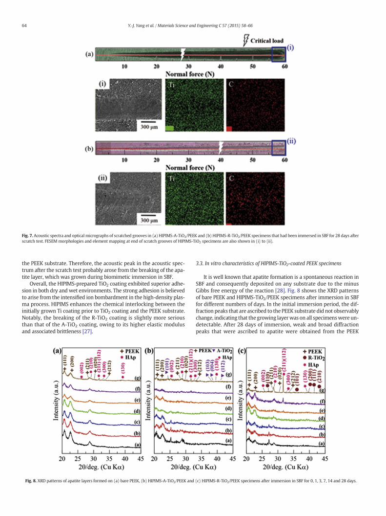
Fig. 7. Acoustic spectra and optical micrographs of scratched grooves in (a) HIPIMS-A-TiO2/PEEK and (b) HIPIMS-R-TiO2/PEEK specimens that had been immersed in SBF for 28 days afterscratch test. FESEM morphologies and element mapping at end of scratch grooves of HIPIMS-TiO2 specimens are also shown in (i) to (ii).
64 Y.-J. Yang et al. / Materials Science and Engineering C 57 (2015) 58–66
the PEEK substrate. Therefore, the acoustic peak in the acoustic spec-trum after the scratch test probably arose from the breaking of the apa-tite layer, which was grown during biomimetic immersion in SBF.
Overall, the HIPIMS-prepared TiO2 coating exhibited superior adhe-sion in both dry and wet environments. The strong adhesion is believedto arise from the intensified ion bombardment in the high-density plas-ma process. HIPIMS enhances the chemical interlocking between theinitially grown Ti coating prior to TiO2 coating and the PEEK substrate.Notably, the breaking of the R-TiO2 coating is slightly more seriousthan that of the A-TiO2 coating, owing to its higher elastic modulusand associated brittleness [27].
Fig. 8. XRD patterns of apatite layers formed on (a) bare PEEK, (b) HIPIMS-A-TiO2/PEEK and
3.3. In vitro characteristics of HIPIMS-TiO2-coated PEEK specimens
It is well known that apatite formation is a spontaneous reaction inSBF and consequently deposited on any substrate due to the minusGibbs free energy of the reaction [28]. Fig. 8 shows the XRD patternsof bare PEEK and HIPIMS-TiO2/PEEK specimens after immersion in SBFfor different numbers of days. In the initial immersion period, the dif-fraction peaks that are ascribed to the PEEK substrate did not observablychange, indicating that the growing layerwas on all specimenswere un-detectable. After 28 days of immersion, weak and broad diffractionpeaks that were ascribed to apatite were obtained from the PEEK
(c) HIPIMS-R-TiO2/PEEK specimens after immersion in SBF for 0, 1, 3, 7, 14 and 28 days.
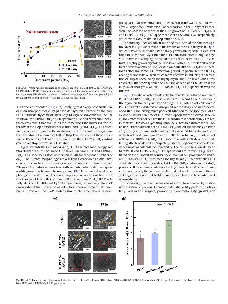
Fig. 9. Ca/Pmolar ratios of obtained apatite layers on bare PEEK, HIPIMS-A-TiO2/PEEK andHIPIMS-R-TiO2/PEEK specimens after immersion in SBF for various numbers of days. Thecorresponding FESEM surface and cross-sectional morphologies of obtained apatite layerson specimens after immersion in SBF for 28 days are also insert.
65Y.-J. Yang et al. / Materials Science and Engineering C 57 (2015) 58–66
substrate, as presented in Fig. 8(a), implying that a very poor crystallineor even amorphous calcium phosphate layer was formed on the barePEEK substrate. By contrast, after only 14 days of immersion in the SBFsolution, the HIPIMS-TiO2/PEEK specimens yielded diffraction peaksthat were attributable to HAp. As the immersion time increased, the in-tensity of the HAp diffraction peaks from both HIPIMS-TiO2/PEEK spec-imens increased significantly, as shown in Fig. 8(b) and (c), suggestingthe formation of a more crystalline HAp layer on each of these speci-mens. These results lead to the conclusion that HIPIMS-TiO2 coatingcan induce HAp growth in SBF solution.
Fig. 9 presents the Ca/P molar ratio, FESEM surface morphology andfilm thickness of the obtained HAp layers on bare PEEK and HIPIMS-TiO2/PEEK specimens after immersion in SBF for different numbers ofdays. The surface morphologies reveal that a crack-like apatite layercovered the surface of specimens when the immersion time reached28 days. This finding is consistent with an earlier observation of typicalapatite growth by biomimetic immersion [18]. The cross-sectional mor-phologies revealed that this apatite layer was a continuous film, withthicknesses of 6 μm, 8.66 μm and 8.97 μm on bare PEEK, HIPIMS-A-TiO2/PEEK and HIPIMS-R-TiO2/PEEK specimens, respectively. The Ca/Pmolar ratio of the surface increased with immersion time for all speci-mens. However, the Ca/P molar ratio of the amorphous calcium
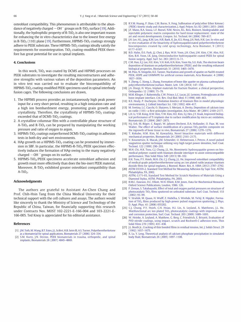
Fig. 10. (a) FESEM images of osteoblast cells that had been cultured for 1 h and 48h onbare PEEKbare PEEK and HIPIMS-TiO2/PEEK specimens.
phosphate that was grown on the PEEK substrate was only 1.30 evenafter 28 days of SBF immersion. For comparison, after 28 days of immer-sion, the Ca/P molar ratios of the HAp grown on HIPIMS-A-TiO2/PEEKand HIPIMS-R-TiO2/PEEK specimens were 1.58 and 1.67, respectively,which were close to that in HAp structure, 1.67.
In summary, the Ca/P molar ratio and thickness of the obtained apa-tite layer in Fig. 9 are similar to the results of the XRD analysis in Fig. 8,which reveal the formation of a slowly grown amorphous Ca-deficientcalcium phosphate layer on bare PEEK substrate after a long 28 daysSBF immersion, verifying the bio-inertness of the bare PEEK [4]. In con-trast, a highly grown crystalline HAp layer with a Ca/P molar ratio closeto the stoichiometry of HAp formed on both HIPIMS-TiO2/PEEK speci-mens after the same SBF immersion period. In particular, the R-TiO2
coating seems to have beenmuchmore effective in inducing the forma-tion of HAp as revealed by the highly crystalline HAp layer with a stoi-chiometry that corresponded to Ca/P molar ratio and the fact that theHAp layer that grew on the HIPIMS-R-TiO2/PEEK specimen was thethicker.
Fig. 10(a) shows osteoblasts cells that had been cultured onto barePEEK and HIPIMS-TiO2/PEEK specimens for 1 h and 48 h. As shown inthe figure, in the early incubation stage (1 h), osteoblast cells on thePEEK substrate exhibited an atrophied morphology and underdevel-oped status, indicating much poor cell adhesion to the specimen. At anextended incubation time of 48 h, few filopodia were observed, so over-all the attachment of cells to the PEEK substrate is considerably limited.In contrast, HIPIMS-TiO2 coatings provide a favorable surface for cell ad-hesion. Osteoblasts on both HIPIMS-TiO2-coated specimens exhibitedvery strong adhesion, with evidence of extended filopodia and evenwell-developed lamellipodia of the cells. In particular, the osteoblastcells on the HIPIMS-R-TiO2/PEEK specimen with well-developed flat-tening attachments and a completely extended cytomatrix provide evi-dence superior osteoblast compatibility. The cell proliferation ability onbare PEEK and HIPIMS-TiO2/PEEK specimens are shown in Fig. 10(b).Based on the quantitative results, the osteoblast cell proliferation abilityon HIPIMS-TiO2/PEEK specimens are significantly superior to the PEEKsubstrate. This clearly indicates that HIPIMS-TiO2 coating in this studypossess cell induction capabilities leading to accelerated cell adhesion,and consequently the increased cell proliferation. Furthermore, the re-sults again validate that R-TiO2 coating exhibits the best osteoblastcompatibility.
In summary, the in vitro characteristics can be enhanced by coatingwith HIPIMS-TiO2 owing its biocompatibility; R-TiO2 performs particu-larly well in this respect, promoting biomimetic HAp growth and
andHIPIMS-TiO2/PEEK specimens. (b) Cell proliferation ability of osteoblast inoculated on
66 Y.-J. Yang et al. / Materials Science and Engineering C 57 (2015) 58–66
osteoblast compatibility. This phenomenon is attributable to the abun-dance of negatively charged−OH− groups on R-TiO2 surface [19]. Addi-tionally, the hydrophilic property of R-TiO2 is also one important reasonfor enhancing the in vitro characteristics due to the lowest free energyin R-TiO2 (110) plane [19]. Furthermore, HIPIMS-TiO2 coatings stronglyadhere to PEEK substrate. These HIPIMS-TiO2 coatings ideally satisfy therequirements for osseointegration. TiO2 coating-modified PEEK there-fore has great potential for use in spinal implants.
4. Conclusions
In this work, TiO2 was coated by DCMS and HIPIMS processes onPEEK substrates to investigate the resulting microstructures and adhe-sive strengths with various values of the deposition parameters. Anin vitro test was carried out to evaluate the biocompatibility ofHIPIMS-TiO2 coating-modified PEEK specimens used in spinal interbodyfusion cages. The following conclusions are drawn,
1. The HIPIMS process provides an instantaneously high peak powerinput for a very short period, resulting in a high ionization rate anda high ion bombardment energy, promoting grain growth andcrystallinity. Therefore, the crystallinity of HIPIMS-TiO2 coatingsexceeded that of DCMS-TiO2 coatings.
2. A crystalline columnar film with a controllable phase structure ofA-TiO2 and R-TiO2 can be prepared by manipulating the workingpressure and ratio of oxygen to argon.
3. HIPIMS-TiO2 coatings outperformedDCMS-TiO2 coatings in adhesiontests in both dry and wet environments.
4. HAp growth on a HIPIMS-TiO2 coating can be promoted by immer-sion in SBF. In particular, the HIPIMS-R-TiO2/PEEK specimen effec-tively induces the formation of HAp owing to the many negativelycharged −OH −groups on its surface.
5. HIPIMS-TiO2/PEEK specimens accelerate osteoblast adhesion andgrowthmust more effectively than does the bio-inert PEEKmaterial.Moreover, R-TiO2 exhibited greater osteoblast compatibility thanA-TiO2.
Acknowledgments
The authors are grateful to Assistant An-Chen Chang andProf. Chih-Hsin Tang from the China Medical University for theirtechnical support with the cell cultures and assays. The authors wouldlike sincerely to thank the Ministry of Science and Technology of theRepublic of China, Taiwan, for financially supporting this researchunder Contracts Nos. MOST 102-2221-E-166-004 and 103-2221-E-166-005. Ted Knoy is appreciated for his editorial assistance.
References
[1] J.M. Toth,M.Wang, B.T. Estes, J.L. Scifert, H.B. Seim III, A.S. Turner, Polyetheretherketoneas a biomaterial for spinal applications, Biomaterials 27 (2006) 324–334.
[2] S.M. Kurtz, J.N. Devine, PEEK biomaterials in trauma, orthopedic, and spinalimplants, Biomaterials 28 (2007) 4845–4869.
[3] R.Y.M. Huang, P. Shao, C.M. Burns, X. Feng, Sulfonation of poly(ether Ether Ketone)(PEEK)-kinetic study and characterization, J. Appl. Polym. Sci. 82 (2001) 2651–2660.
[4] J.F. Mano, R.A. Sousa, L.F. Boesel, N.M. Neves, R.L. Reis, Bioinert, biodegradable andinjectable polymeric matrix composites for hard tissue replacement: state of theart and recent developments, Compos. Sci. Technol. 64 (2004) 789–817.
[5] J.H. Lee, H.L. Jang, K.M. Lee, H.R. Baek, K. Jin, K.S. Hong, J.H. Noh, H.K. Lee, In vitro andin vivo evaluation of the bioactivity of hydroxyapatitecoated polyetheretherketonebiocomposites created by cold spray technology, Acta Biomater. 9 (2013)6177–6187.
[6] B.D. Hahn, D.S. Park, J.J. Choi, J. Ryu, W.H. Yoon, J.H. Choi, J.W. Kim, C.W. Ahn, H.E.Kim, B.H. Yoon, I.K. Jung, Osteoconductive hydroxyapatite coated PEEK for spinalfusion surgery, Appl. Surf. Sci. 283 (2013) 6–11.
[7] C.M. Han, E.J. Lee, H.E. Kim, Y.H. Koh, K.N. Kim, Yoon Ha, S.U. Kuh, The electron beamdeposition of titanium on polyetheretherketone (PEEK) and the resulting enhancedbiological properties, Biomaterials 31 (2010) 3465–3470.
[8] M. Pino, N. Stingelin, K.E. Tanner, Nucleation and growth of apatite on NaOH-treatedPEEK, HDPE and UHMWPE for artificial cornea materials, Acta Biomater. 4 (2008)1827–1836.
[9] Y. Zheng, C. Xiong, L. Zhang, Formation of bone-like apatite on plasma-carboxylatedpoly(etheretherketone)surface, Mater. Lett. 126 (2014) 147–150.
[10] J.A. Disegi, H. Wyss, Implant materials for fracture fixation: a clinical perspective,Orthopedics 12 (1989) 75–79.
[11] M.M. Klinger, F. Rahemtulla, C.W. Prince, L.C. Lucas, J.E. Lemons, Proteoglycans at thebone-implant interface, Crit. Rev. Oral Biol. Med. 9 (1998) 449–463.
[12] K.E. Healy, P. Ducheyne, Oxidation kinetics of titanium film in model physiologicenvironments, J. Colloid Interface Sci. 150 (1992) 404–417.
[13] M. Svetina, L.C. Ciacchi, O. Sbaizero, S. Meriani, A. Devita, Deposition of calcium ionson rutile (110)—a first-principles investigation, Acta Mater. 49 (2001) 2169–2177.
[14] L.H. Li, Y.M. Kong, H.W. Kim, Y.W. Kim, H.E. Kim, S.J. Heo, J.Y. Koak, Improved biolog-ical performance of Ti implants due to surface modification by micro-arc oxidation,Biomaterials 25 (2004) 2867–2875.
[15] H.J. Erli, M. Rüger, C. Ragoβ, W. Jahnen-Dechent, D.A. Hollander, O. Paar, M. vonWalter, The effect of surface modification of a porous TiO2/perlite composite onthe ingrowth of bone tissue in vivo, Biomaterials 27 (2006) 1270–1276.
[16] T. Kokubo, H.M. Kim, M. Kawashita, Novel bioactive materials with differentmechanical properties, Biomaterials 24 (2003) 2161–2175.
[17] V. Kouznetsov, K. Macak, J.M. Schneider, U. Helmersson, I. Petrov, A novel pulsedmagnetron sputter technique utilizing very high target power densities, Surf. Coat.Technol. 122 (1999) 290–293.
[18] M.H. Chi, H.K. Tsou, C.J. Chung, J.L. He, Biomimetic hydroxyapatite grown on bio-medical polymer coated with titanium dioxide interlayer to assist osteocompatibleperformance, Thin Solid Films 549 (2013) 98–102.
[19] H.K. Tsou, P.Y. Hsieh, M.H. Chi, C.J. Chung, J.L. He, Improved osteoblast compatibilityof medical-grade polyetheretherketone using arc ion plated rutile/anatase titaniumdioxide films for spinal implants, J. Biomed. Mater. Res. A. 100A (2012) 2787–2792.
[20] ASTM D3359-2, Standard Test Method for Measuring Adhesion by Tape Test, ASTM,Philadelphia, PA, 2002.
[21] ASTM, G171-03, Standard Test Method for Scratch Hardness of Materials Using aDiamond Stylus, ASTM, Philadelphia, PA, 2003.
[22] R.M.C. Dawson, D.C. Elliott, W.H. Elliott, K.M. Jones, Data for Biochemical Research,Oxford Science Publications, Loudon, 1986. 126.
[23] P. Zeman, S. Takabayashi, Effect of total and oxygen partial pressures on structure ofphotocatalytic TiO2 films sputtered on unheated substrate, Surf. Coat. Technol. 153(2002) 93–99.
[24] V. Straňák, M. Quaas, H. Wulff, Z. Hubička, S. Wrehde, M. Tichý, R. Hippler, Forma-tion of TiOx films produced by high-power pulsed magnetron sputtering, J. Phys.D. Appl. Phys. 41 (2008) 055202.
[25] C.J. Chung, P.Y. Hsieh, C.H. Hsiao, H.I. Lin, A. Leyland, A. Matthews, J.L. He,Mutifunctional arc ion plated TiO2 photocatalytic coatings with improved wearand corrosion protection, Surf. Coat. Technol. 203 (2009) 1689–1693.
[26] W. Heinke, A. Leyland, A. Matthew, G. Berg, C. Friendrich, E. Briszeit, Evaluation ofPVD nitride coatings, using impact, scratch and Rockwell-C adhesion tests, ThinSolid Films 270 (1995) 431–438.
[27] J.L. Beuth Jr., Cracking of thin bonded films in residual tension, Int. J. Solids Struct. 29(1992) 1657–1675.
[28] X. Lu, Y. Leng, Theoretical analysis of calcium phosphate precipitation in simulatedbody fluid, Biomaterials 26 (2005) 1097–1108.

本文献由“学霸图书馆-文献云下载”收集自网络,仅供学习交流使用。
学霸图书馆(www.xuebalib.com)是一个“整合众多图书馆数据库资源,
提供一站式文献检索和下载服务”的24 小时在线不限IP
图书馆。
图书馆致力于便利、促进学习与科研,提供最强文献下载服务。
图书馆导航:
图书馆首页 文献云下载 图书馆入口 外文数据库大全 疑难文献辅助工具