Embed Size (px)
Citation preview
Materials handling in flexible manufacturing systems 121
Materials handling in flexible manufacturing systems
Dr. Tauseef Aized
X
Materials handling in flexible manufacturing systems
Dr. Tauseef Aized
Professor, Department of Mechanical, Mechatrnics and Manufacturing Engineering, KSK Campus, University of Engineering and Technology, Lahore, Pakistan
1. Introduction
Material handling can be defined as an integrated system involving such activities as moving, handling, storing and controlling of materials by means of gravity, manual effort or power activated machinery. Moving materials utilize time and space. Any movement of materials requires that the size, shape, weight and condition of the material, as well as the path and frequency of the move be analyzed. Storing materials provide a buffer between operations. It facilitates the efficient use of people and machines and provides an efficient organization of materials. The considerations for material system design include the size, weight, condition and stack ability of materials; the required throughput; and building constraints such as floor loading, floor condition, column spacing etc. The protection of materials include both packaging and protecting against damage and theft of material as well as the use of safeguards on the information system to include protection against the material being mishandled, misplaced, misappropriated and processed in a wrong sequence. Controlling material includes both physical control as well as status of material control. Physical control is the orientation of sequence and space between material movements. Status control is the real time awareness of the location, amount, destination, origin, ownership and schedule of material. Maintaining the correct degree of control is a challenge because the right amount of control depends upon the culture of the organization and the people who manage and perform material handling functions. Material handling is an important area of concern in flexible manufacturing systems because more than 80 % of time that material spends on a shop floor is spent either in waiting or in transportation, although both these activities are non-value added activities. Efficient material handling is needed for less congestion, timely delivery and reduced idle time of machines due to non-availability or accumulation of materials at workstations. Safe handling of materials is important in a plant as it reduces wastage, breakage, loss and scrapes etc.
6
Future Manufacturing Systems122
2. Principles of material handlings
The material handling principles provide fundamentals of material handling practices and provide guidance to material handling system designers. The following is a brief description of material handling principles.
2.1 Planning principle All material handling should be the result of a deliberate plan where the needs, performance objectives and functional specification of the proposed methods are completely defined at the outset. In its simplest form a material handing plan defines the material (what) and the moves (when and where); together they define the method (how and who).
2.2 Standardization principle Standardize handling methods and equipments wherever possible. Material handling methods, equipment, controls and software should be standardized within the limits of achieving overall performance objectives and without sacrificing needed flexibility, modularity and throughout anticipation of changing future requirements.
2.3 Ergonomic principle Human capabilities and limitations must be recognized and respected in the design of material handling tasks and equipment to ensure safe and effective operations. Equipments should be selected that eliminates repetitive and strenuous manual labor and which effectively interacts with human operators and users.
2.4 Flexibility principle Use methods and equipments that can perform a variety of tasks under varying operating conditions.
2.5 Simplification Simplify material handling by eliminating, reducing or combining unnecessary movements and equipments.
2.6 Gravity Utilize gravity to move material wherever possible.
2.7 Layout Prepare an operation sequence and equipment layout for all viable system solutions and then select the best possible configuration.
2.8 Cost Compare the economic justification of alternate solutions with equipment and methods on the basis of economic effectiveness as measured by expenses per unit handled.
2.9 Maintenance Prepare a plan for preventive maintenance and scheduled repairs on all material handling equipments.
2.10 Unit load principle A unit load is one that can be stored or moved as a single entity at one time, such as a pallet, container or tote, regardless of the number of individual items that make up the load. Unit loads shall be appropriately sized and configured in a way which achieves the material flow and inventory objectives at each stage in the supply chain.
2.11 Space utilization principle Effective and efficient use must be made of all available space. In work areas, cluttered and unorganized spaces and blocked aisles should be eliminated. When transporting loads within a facility, the use of overhead space should be considered as an option.
2.12 System principle Material movement and storage activities should be fully integrated to form a coordinated, operational system which spans receiving, inspection, storage, production, assembly, packaging, unitizing, order selection, shipping, transportation and the handling of returns. Systems integration should encompass the entire supply chain including reverse logistics. It should include suppliers, manufacturers, distributors and customers.
2.13 Automation principle Material handling operations should be mechanized and/or automated where feasible to improve operational efficiency, increase responsiveness, and improve consistency and
predictability. 2.14 Environmental principle Environmental impact and energy consumption should be considered as criteria when designing or selecting alternative equipment and material handling systems.
2.15 Life cycle cost principle A thorough economic analysis should account for the entire life cycle of all material handling equipment and resulting systems. Life cycle costs include capital investment, installation, setup and equipment programming, training, system testing and acceptance, operating (labor, utilities, etc.), maintenance and repair, reuse value, and ultimate disposal
3. Material Transport Equipment
International Materials Management Society has classified equipment as (1) conveyor, (2) cranes, elevators, and hoists, (3) positioning, weighing, and control equipment, (4) industrial vehicles, (5) motor vehicles, (6) railroad cars, (7) marine carriers, (8) aircraft, and (9)
Materials handling in flexible manufacturing systems 123
2. Principles of material handlings
The material handling principles provide fundamentals of material handling practices and provide guidance to material handling system designers. The following is a brief description of material handling principles.
2.1 Planning principle All material handling should be the result of a deliberate plan where the needs, performance objectives and functional specification of the proposed methods are completely defined at the outset. In its simplest form a material handing plan defines the material (what) and the moves (when and where); together they define the method (how and who).
2.2 Standardization principle Standardize handling methods and equipments wherever possible. Material handling methods, equipment, controls and software should be standardized within the limits of achieving overall performance objectives and without sacrificing needed flexibility, modularity and throughout anticipation of changing future requirements.
2.3 Ergonomic principle Human capabilities and limitations must be recognized and respected in the design of material handling tasks and equipment to ensure safe and effective operations. Equipments should be selected that eliminates repetitive and strenuous manual labor and which effectively interacts with human operators and users.
2.4 Flexibility principle Use methods and equipments that can perform a variety of tasks under varying operating conditions.
2.5 Simplification Simplify material handling by eliminating, reducing or combining unnecessary movements and equipments.
2.6 Gravity Utilize gravity to move material wherever possible.
2.7 Layout Prepare an operation sequence and equipment layout for all viable system solutions and then select the best possible configuration.
2.8 Cost Compare the economic justification of alternate solutions with equipment and methods on the basis of economic effectiveness as measured by expenses per unit handled.
2.9 Maintenance Prepare a plan for preventive maintenance and scheduled repairs on all material handling equipments.
2.10 Unit load principle A unit load is one that can be stored or moved as a single entity at one time, such as a pallet, container or tote, regardless of the number of individual items that make up the load. Unit loads shall be appropriately sized and configured in a way which achieves the material flow and inventory objectives at each stage in the supply chain.
2.11 Space utilization principle Effective and efficient use must be made of all available space. In work areas, cluttered and unorganized spaces and blocked aisles should be eliminated. When transporting loads within a facility, the use of overhead space should be considered as an option.
2.12 System principle Material movement and storage activities should be fully integrated to form a coordinated, operational system which spans receiving, inspection, storage, production, assembly, packaging, unitizing, order selection, shipping, transportation and the handling of returns. Systems integration should encompass the entire supply chain including reverse logistics. It should include suppliers, manufacturers, distributors and customers.
2.13 Automation principle Material handling operations should be mechanized and/or automated where feasible to improve operational efficiency, increase responsiveness, and improve consistency and
predictability. 2.14 Environmental principle Environmental impact and energy consumption should be considered as criteria when designing or selecting alternative equipment and material handling systems.
2.15 Life cycle cost principle A thorough economic analysis should account for the entire life cycle of all material handling equipment and resulting systems. Life cycle costs include capital investment, installation, setup and equipment programming, training, system testing and acceptance, operating (labor, utilities, etc.), maintenance and repair, reuse value, and ultimate disposal
3. Material Transport Equipment
International Materials Management Society has classified equipment as (1) conveyor, (2) cranes, elevators, and hoists, (3) positioning, weighing, and control equipment, (4) industrial vehicles, (5) motor vehicles, (6) railroad cars, (7) marine carriers, (8) aircraft, and (9)
Future Manufacturing Systems124
containers and supports. The following provides the details of material transport equipments.
3.1 Conveyor Systems A Conveyor is used when a material is moved very frequently between specific points and the path between points is fixed. Conveyors combined with modern identification and recognition systems like bar code technologies have played a significant role in the transportation and sorting of a large variety of products in modern warehouses. Some of the common types of conveyors are:
Roller conveyor Skate- wheel conveyor Belt conveyor In- floor towline conveyor Overhead trolley conveyor Cart-on-track conveyor
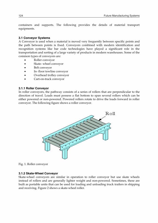
3.1.1 Roller Conveyor In roller conveyors, the pathway consists of a series of rollers that are perpendicular to the direction of travel. Loads must possess a flat bottom to span several rollers which can be either powered or non-powered. Powered rollers rotate to drive the loads forward in roller conveyor. The following figure shows a roller conveyor.
Fig. 1. Roller conveyor
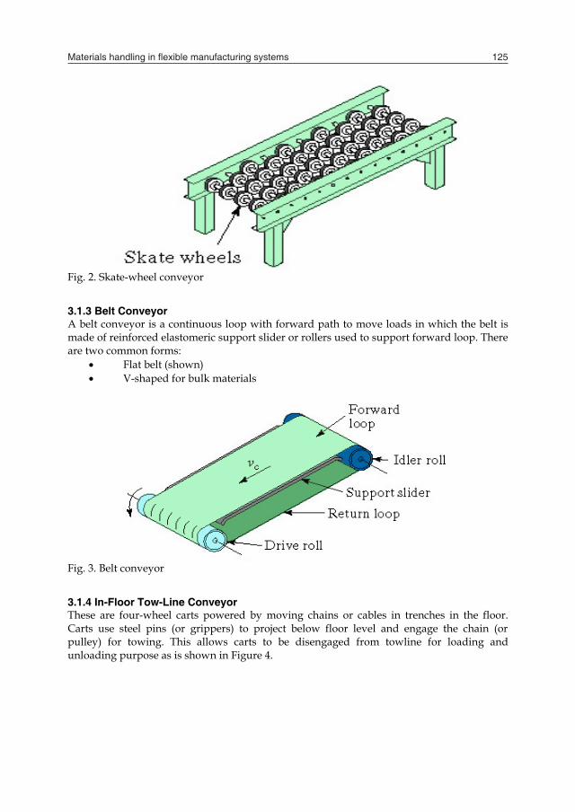
3.1.2 Skate-Wheel Conveyor Skate-wheel conveyors are similar in operation to roller conveyor but use skate wheels instead of rollers and are generally lighter weight and non-powered. Sometimes, these are built as portable units that can be used for loading and unloading truck trailers in shipping and receiving. Figure 2 shows a skate-wheel roller.
Fig. 2. Skate-wheel conveyor
3.1.3 Belt Conveyor A belt conveyor is a continuous loop with forward path to move loads in which the belt is made of reinforced elastomeric support slider or rollers used to support forward loop. There are two common forms:
Flat belt (shown) V-shaped for bulk materials
Fig. 3. Belt conveyor
3.1.4 In-Floor Tow-Line Conveyor These are four-wheel carts powered by moving chains or cables in trenches in the floor. Carts use steel pins (or grippers) to project below floor level and engage the chain (or pulley) for towing. This allows carts to be disengaged from towline for loading and unloading purpose as is shown in Figure 4.
Materials handling in flexible manufacturing systems 125
containers and supports. The following provides the details of material transport equipments.
3.1 Conveyor Systems A Conveyor is used when a material is moved very frequently between specific points and the path between points is fixed. Conveyors combined with modern identification and recognition systems like bar code technologies have played a significant role in the transportation and sorting of a large variety of products in modern warehouses. Some of the common types of conveyors are:
Roller conveyor Skate- wheel conveyor Belt conveyor In- floor towline conveyor Overhead trolley conveyor Cart-on-track conveyor
3.1.1 Roller Conveyor In roller conveyors, the pathway consists of a series of rollers that are perpendicular to the direction of travel. Loads must possess a flat bottom to span several rollers which can be either powered or non-powered. Powered rollers rotate to drive the loads forward in roller conveyor. The following figure shows a roller conveyor.
Fig. 1. Roller conveyor
3.1.2 Skate-Wheel Conveyor Skate-wheel conveyors are similar in operation to roller conveyor but use skate wheels instead of rollers and are generally lighter weight and non-powered. Sometimes, these are built as portable units that can be used for loading and unloading truck trailers in shipping and receiving. Figure 2 shows a skate-wheel roller.
Fig. 2. Skate-wheel conveyor
3.1.3 Belt Conveyor A belt conveyor is a continuous loop with forward path to move loads in which the belt is made of reinforced elastomeric support slider or rollers used to support forward loop. There are two common forms:
Flat belt (shown) V-shaped for bulk materials
Fig. 3. Belt conveyor
3.1.4 In-Floor Tow-Line Conveyor These are four-wheel carts powered by moving chains or cables in trenches in the floor. Carts use steel pins (or grippers) to project below floor level and engage the chain (or pulley) for towing. This allows carts to be disengaged from towline for loading and unloading purpose as is shown in Figure 4.
Future Manufacturing Systems126
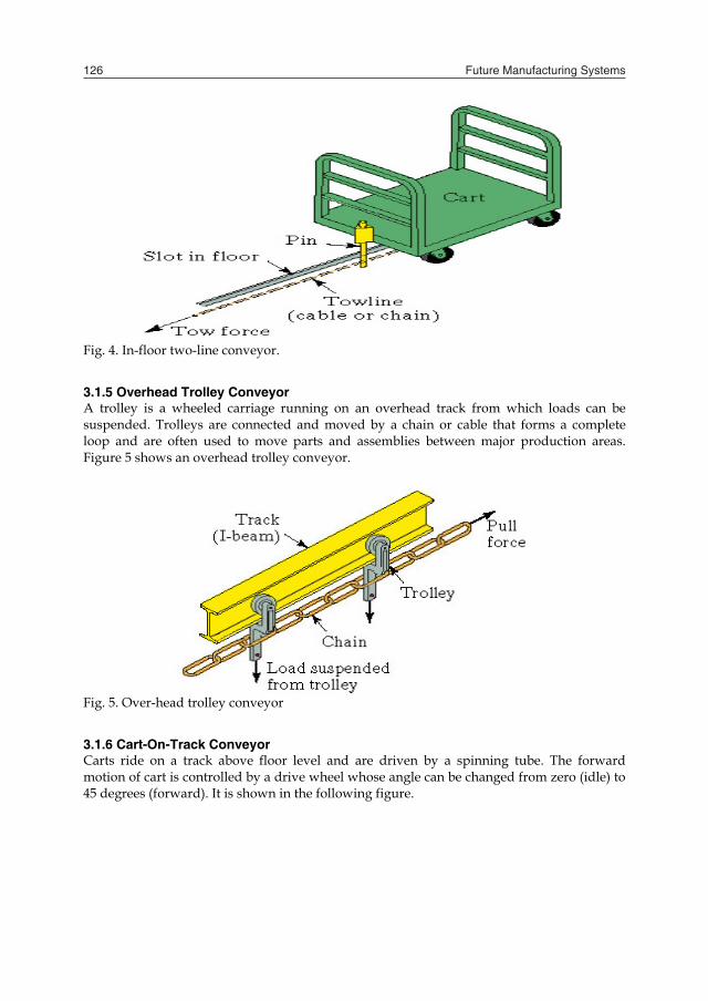
Fig. 4. In-floor two-line conveyor.
3.1.5 Overhead Trolley Conveyor A trolley is a wheeled carriage running on an overhead track from which loads can be suspended. Trolleys are connected and moved by a chain or cable that forms a complete loop and are often used to move parts and assemblies between major production areas. Figure 5 shows an overhead trolley conveyor.
Fig. 5. Over-head trolley conveyor
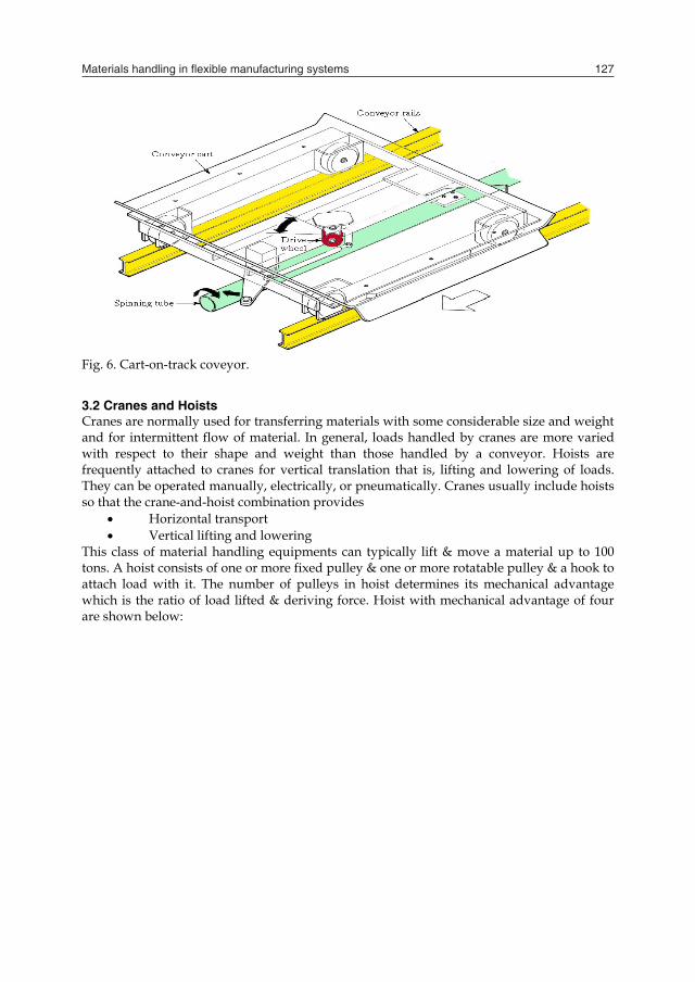
3.1.6 Cart-On-Track Conveyor Carts ride on a track above floor level and are driven by a spinning tube. The forward motion of cart is controlled by a drive wheel whose angle can be changed from zero (idle) to 45 degrees (forward). It is shown in the following figure.
Fig. 6. Cart-on-track coveyor.
3.2 Cranes and Hoists Cranes are normally used for transferring materials with some considerable size and weight and for intermittent flow of material. In general, loads handled by cranes are more varied with respect to their shape and weight than those handled by a conveyor. Hoists are frequently attached to cranes for vertical translation that is, lifting and lowering of loads. They can be operated manually, electrically, or pneumatically. Cranes usually include hoists so that the crane-and-hoist combination provides
Horizontal transport Vertical lifting and lowering
This class of material handling equipments can typically lift & move a material up to 100 tons. A hoist consists of one or more fixed pulley & one or more rotatable pulley & a hook to attach load with it. The number of pulleys in hoist determines its mechanical advantage which is the ratio of load lifted & deriving force. Hoist with mechanical advantage of four are shown below:
Materials handling in flexible manufacturing systems 127
Fig. 4. In-floor two-line conveyor.
3.1.5 Overhead Trolley Conveyor A trolley is a wheeled carriage running on an overhead track from which loads can be suspended. Trolleys are connected and moved by a chain or cable that forms a complete loop and are often used to move parts and assemblies between major production areas. Figure 5 shows an overhead trolley conveyor.
Fig. 5. Over-head trolley conveyor
3.1.6 Cart-On-Track Conveyor Carts ride on a track above floor level and are driven by a spinning tube. The forward motion of cart is controlled by a drive wheel whose angle can be changed from zero (idle) to 45 degrees (forward). It is shown in the following figure.
Fig. 6. Cart-on-track coveyor.
3.2 Cranes and Hoists Cranes are normally used for transferring materials with some considerable size and weight and for intermittent flow of material. In general, loads handled by cranes are more varied with respect to their shape and weight than those handled by a conveyor. Hoists are frequently attached to cranes for vertical translation that is, lifting and lowering of loads. They can be operated manually, electrically, or pneumatically. Cranes usually include hoists so that the crane-and-hoist combination provides
Horizontal transport Vertical lifting and lowering
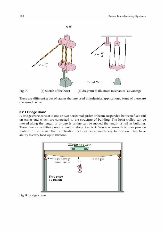
This class of material handling equipments can typically lift & move a material up to 100 tons. A hoist consists of one or more fixed pulley & one or more rotatable pulley & a hook to attach load with it. The number of pulleys in hoist determines its mechanical advantage which is the ratio of load lifted & deriving force. Hoist with mechanical advantage of four are shown below:
Future Manufacturing Systems128
Fig. 7. (a) Sketch of the hoist (b) diagram to illustrate mechanical advantage There are different types of cranes that are used in industrial applications. Some of these are discussed below.
3.2.1 Bridge Crane A bridge crane consist of one or two horizontal girder or beam suspended between fixed rail on either end which are connected to the structure of building. The hoist trolley can be moved along the length of bridge & bridge can be moved the length of rail in building. These two capabilities provide motion along X-axis & Y-axis whereas hoist can provide motion in the z-axis. Their application includes heavy machinery fabrication. They have ability to carry load up to 100 tons.
Fig. 8. Bridge crane
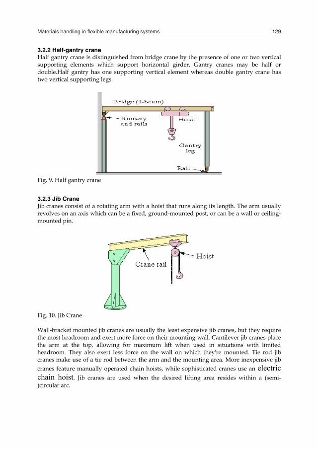
3.2.2 Half-gantry crane Half gantry crane is distinguished from bridge crane by the presence of one or two vertical supporting elements which support horizontal girder. Gantry cranes may be half or double.Half gantry has one supporting vertical element whereas double gantry crane has two vertical supporting legs.
Fig. 9. Half gantry crane
3.2.3 Jib Crane Jib cranes consist of a rotating arm with a hoist that runs along its length. The arm usually revolves on an axis which can be a fixed, ground-mounted post, or can be a wall or ceiling-mounted pin.
Fig. 10. Jib Crane Wall-bracket mounted jib cranes are usually the least expensive jib cranes, but they require the most headroom and exert more force on their mounting wall. Cantilever jib cranes place the arm at the top, allowing for maximum lift when used in situations with limited headroom. They also exert less force on the wall on which they're mounted. Tie rod jib cranes make use of a tie rod between the arm and the mounting area. More inexpensive jib cranes feature manually operated chain hoists, while sophisticated cranes use an electric chain hoist. Jib cranes are used when the desired lifting area resides within a (semi-)circular arc.
Materials handling in flexible manufacturing systems 129
Fig. 7. (a) Sketch of the hoist (b) diagram to illustrate mechanical advantage There are different types of cranes that are used in industrial applications. Some of these are discussed below.
3.2.1 Bridge Crane A bridge crane consist of one or two horizontal girder or beam suspended between fixed rail on either end which are connected to the structure of building. The hoist trolley can be moved along the length of bridge & bridge can be moved the length of rail in building. These two capabilities provide motion along X-axis & Y-axis whereas hoist can provide motion in the z-axis. Their application includes heavy machinery fabrication. They have ability to carry load up to 100 tons.
Fig. 8. Bridge crane
3.2.2 Half-gantry crane Half gantry crane is distinguished from bridge crane by the presence of one or two vertical supporting elements which support horizontal girder. Gantry cranes may be half or double.Half gantry has one supporting vertical element whereas double gantry crane has two vertical supporting legs.
Fig. 9. Half gantry crane
3.2.3 Jib Crane Jib cranes consist of a rotating arm with a hoist that runs along its length. The arm usually revolves on an axis which can be a fixed, ground-mounted post, or can be a wall or ceiling-mounted pin.
Fig. 10. Jib Crane Wall-bracket mounted jib cranes are usually the least expensive jib cranes, but they require the most headroom and exert more force on their mounting wall. Cantilever jib cranes place the arm at the top, allowing for maximum lift when used in situations with limited headroom. They also exert less force on the wall on which they're mounted. Tie rod jib cranes make use of a tie rod between the arm and the mounting area. More inexpensive jib cranes feature manually operated chain hoists, while sophisticated cranes use an electric chain hoist. Jib cranes are used when the desired lifting area resides within a (semi-)circular arc.
Future Manufacturing Systems130
3.2.4 Stacker Crane It is similar to a bridge crane. The major difference is that, instead of using a hoist, the stacker crane uses a mast with forks or a platform to handle unit loads. Stacker cranes are generally used for storing and retrieving unit loads in storage racks, especially in high-rise applications.
4. Automated Retrieval and storage equipments
Storage equipments can be in the form of racks, shelves, bins and drawers. Among these, storage rack is probably the most common form of storage equipment. There are numerous variants and configurations of storage racks, which include single-deep, double-deep rack, cantilever rack etc. and configurations that are designed to facilitate specific storage and retrieval operations drive-through, flow-through etc. More sophisticated retrieval and storage system combine the use of storage equipment, storing and retrieval machines and control that are manifested in a modern automated storage/ retrieval system.
5. Automated Guided Vehicles
An Automated Guided Vehicle System (AGVS) is a material handling system that uses independently operated, self-propelled vehicles guided along defined pathways in the facility floor. It is an automated material handling system which moves along predefined and preprogrammed path along an aisle from one station to another. The main parts of an AGV include structure, drive system, steering mechanism, power source (battery) and onboard computer for control.
5.1 Types of AGV The following are common types of AGVs.
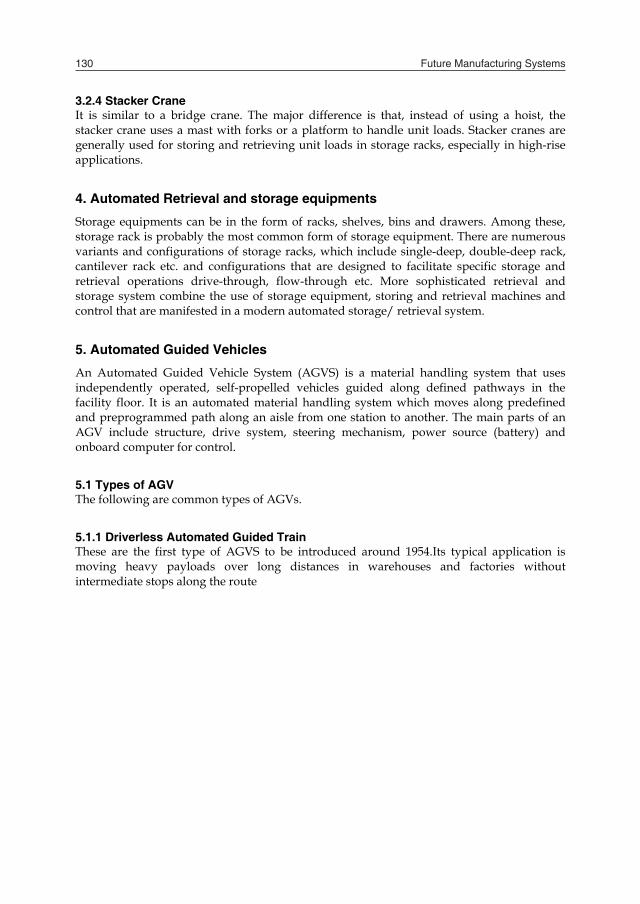
5.1.1 Driverless Automated Guided Train These are the first type of AGVS to be introduced around 1954.Its typical application is moving heavy payloads over long distances in warehouses and factories without intermediate stops along the route
Fig. 11. Driverless automated guided vehicle
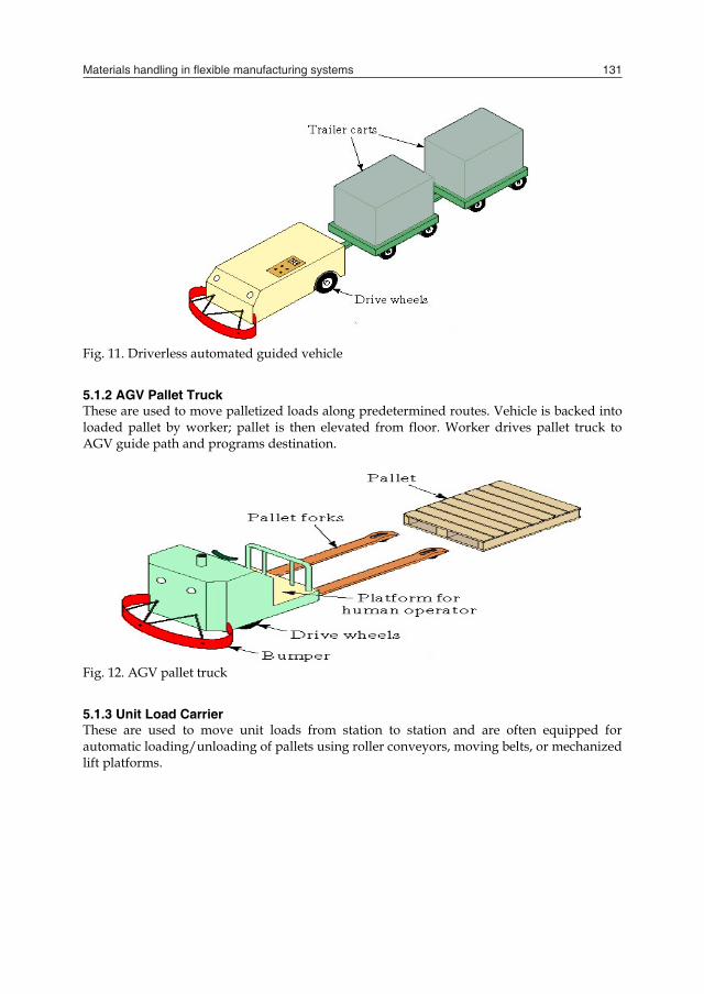
5.1.2 AGV Pallet Truck These are used to move palletized loads along predetermined routes. Vehicle is backed into loaded pallet by worker; pallet is then elevated from floor. Worker drives pallet truck to AGV guide path and programs destination.
Fig. 12. AGV pallet truck
5.1.3 Unit Load Carrier These are used to move unit loads from station to station and are often equipped for automatic loading/unloading of pallets using roller conveyors, moving belts, or mechanized lift platforms.
Materials handling in flexible manufacturing systems 131
3.2.4 Stacker Crane It is similar to a bridge crane. The major difference is that, instead of using a hoist, the stacker crane uses a mast with forks or a platform to handle unit loads. Stacker cranes are generally used for storing and retrieving unit loads in storage racks, especially in high-rise applications.
4. Automated Retrieval and storage equipments
Storage equipments can be in the form of racks, shelves, bins and drawers. Among these, storage rack is probably the most common form of storage equipment. There are numerous variants and configurations of storage racks, which include single-deep, double-deep rack, cantilever rack etc. and configurations that are designed to facilitate specific storage and retrieval operations drive-through, flow-through etc. More sophisticated retrieval and storage system combine the use of storage equipment, storing and retrieval machines and control that are manifested in a modern automated storage/ retrieval system.
5. Automated Guided Vehicles
An Automated Guided Vehicle System (AGVS) is a material handling system that uses independently operated, self-propelled vehicles guided along defined pathways in the facility floor. It is an automated material handling system which moves along predefined and preprogrammed path along an aisle from one station to another. The main parts of an AGV include structure, drive system, steering mechanism, power source (battery) and onboard computer for control.
5.1 Types of AGV The following are common types of AGVs.
5.1.1 Driverless Automated Guided Train These are the first type of AGVS to be introduced around 1954.Its typical application is moving heavy payloads over long distances in warehouses and factories without intermediate stops along the route
Fig. 11. Driverless automated guided vehicle
5.1.2 AGV Pallet Truck These are used to move palletized loads along predetermined routes. Vehicle is backed into loaded pallet by worker; pallet is then elevated from floor. Worker drives pallet truck to AGV guide path and programs destination.
Fig. 12. AGV pallet truck
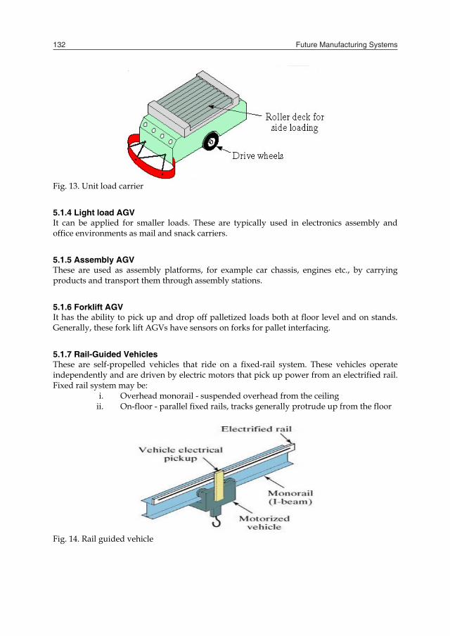
5.1.3 Unit Load Carrier These are used to move unit loads from station to station and are often equipped for automatic loading/unloading of pallets using roller conveyors, moving belts, or mechanized lift platforms.
Future Manufacturing Systems132
Fig. 13. Unit load carrier
5.1.4 Light load AGV It can be applied for smaller loads. These are typically used in electronics assembly and office environments as mail and snack carriers.
5.1.5 Assembly AGV These are used as assembly platforms, for example car chassis, engines etc., by carrying products and transport them through assembly stations.
5.1.6 Forklift AGV It has the ability to pick up and drop off palletized loads both at floor level and on stands. Generally, these fork lift AGVs have sensors on forks for pallet interfacing.
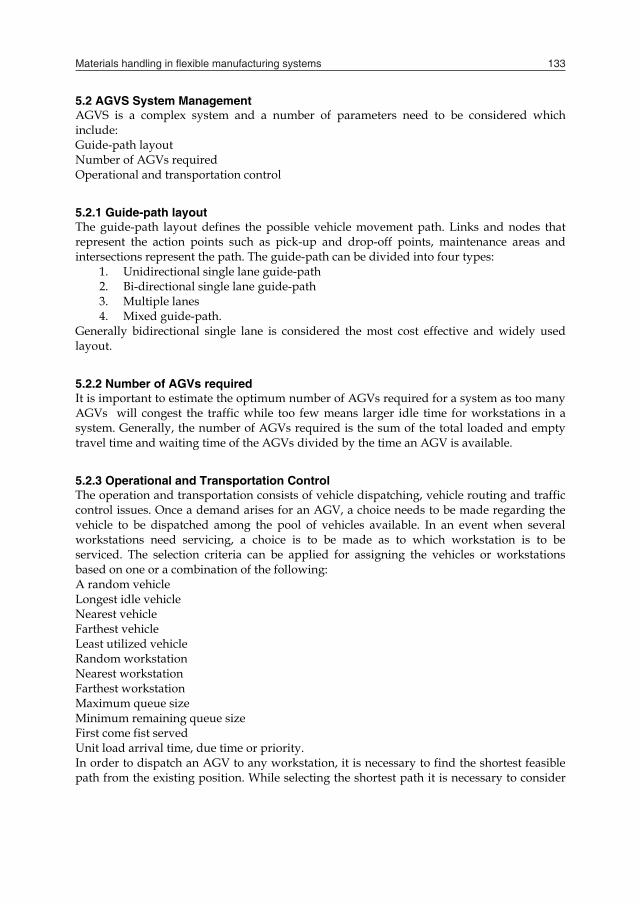
5.1.7 Rail-Guided Vehicles These are self-propelled vehicles that ride on a fixed-rail system. These vehicles operate independently and are driven by electric motors that pick up power from an electrified rail. Fixed rail system may be:
i. Overhead monorail - suspended overhead from the ceiling ii. On-floor - parallel fixed rails, tracks generally protrude up from the floor
Fig. 14. Rail guided vehicle
5.2 AGVS System Management AGVS is a complex system and a number of parameters need to be considered which include: Guide-path layout Number of AGVs required Operational and transportation control
5.2.1 Guide-path layout The guide-path layout defines the possible vehicle movement path. Links and nodes that represent the action points such as pick-up and drop-off points, maintenance areas and intersections represent the path. The guide-path can be divided into four types:
1. Unidirectional single lane guide-path 2. Bi-directional single lane guide-path 3. Multiple lanes 4. Mixed guide-path.
Generally bidirectional single lane is considered the most cost effective and widely used layout.
5.2.2 Number of AGVs required It is important to estimate the optimum number of AGVs required for a system as too many AGVs will congest the traffic while too few means larger idle time for workstations in a system. Generally, the number of AGVs required is the sum of the total loaded and empty travel time and waiting time of the AGVs divided by the time an AGV is available.
5.2.3 Operational and Transportation Control The operation and transportation consists of vehicle dispatching, vehicle routing and traffic control issues. Once a demand arises for an AGV, a choice needs to be made regarding the vehicle to be dispatched among the pool of vehicles available. In an event when several workstations need servicing, a choice is to be made as to which workstation is to be serviced. The selection criteria can be applied for assigning the vehicles or workstations based on one or a combination of the following: A random vehicle Longest idle vehicle Nearest vehicle Farthest vehicle Least utilized vehicle Random workstation Nearest workstation Farthest workstation Maximum queue size Minimum remaining queue size First come fist served Unit load arrival time, due time or priority. In order to dispatch an AGV to any workstation, it is necessary to find the shortest feasible path from the existing position. While selecting the shortest path it is necessary to consider
Materials handling in flexible manufacturing systems 133
Fig. 13. Unit load carrier
5.1.4 Light load AGV It can be applied for smaller loads. These are typically used in electronics assembly and office environments as mail and snack carriers.
5.1.5 Assembly AGV These are used as assembly platforms, for example car chassis, engines etc., by carrying products and transport them through assembly stations.
5.1.6 Forklift AGV It has the ability to pick up and drop off palletized loads both at floor level and on stands. Generally, these fork lift AGVs have sensors on forks for pallet interfacing.
5.1.7 Rail-Guided Vehicles These are self-propelled vehicles that ride on a fixed-rail system. These vehicles operate independently and are driven by electric motors that pick up power from an electrified rail. Fixed rail system may be:
i. Overhead monorail - suspended overhead from the ceiling ii. On-floor - parallel fixed rails, tracks generally protrude up from the floor
Fig. 14. Rail guided vehicle
5.2 AGVS System Management AGVS is a complex system and a number of parameters need to be considered which include: Guide-path layout Number of AGVs required Operational and transportation control
5.2.1 Guide-path layout The guide-path layout defines the possible vehicle movement path. Links and nodes that represent the action points such as pick-up and drop-off points, maintenance areas and intersections represent the path. The guide-path can be divided into four types:
1. Unidirectional single lane guide-path 2. Bi-directional single lane guide-path 3. Multiple lanes 4. Mixed guide-path.
Generally bidirectional single lane is considered the most cost effective and widely used layout.
5.2.2 Number of AGVs required It is important to estimate the optimum number of AGVs required for a system as too many AGVs will congest the traffic while too few means larger idle time for workstations in a system. Generally, the number of AGVs required is the sum of the total loaded and empty travel time and waiting time of the AGVs divided by the time an AGV is available.
5.2.3 Operational and Transportation Control The operation and transportation consists of vehicle dispatching, vehicle routing and traffic control issues. Once a demand arises for an AGV, a choice needs to be made regarding the vehicle to be dispatched among the pool of vehicles available. In an event when several workstations need servicing, a choice is to be made as to which workstation is to be serviced. The selection criteria can be applied for assigning the vehicles or workstations based on one or a combination of the following: A random vehicle Longest idle vehicle Nearest vehicle Farthest vehicle Least utilized vehicle Random workstation Nearest workstation Farthest workstation Maximum queue size Minimum remaining queue size First come fist served Unit load arrival time, due time or priority. In order to dispatch an AGV to any workstation, it is necessary to find the shortest feasible path from the existing position. While selecting the shortest path it is necessary to consider
Future Manufacturing Systems134
only those paths which are free and not occupied by vehicles. It may also be necessary to consider the future positions of the vehicles in the route in addition to their current occupied positions. In identifying the traffic control systems for AGVs movement, the approaches that can be used are forward sensing control, zone sensing control and combinatorial control. In forward sensing control, an AGV is equipped with obstruction detecting sensors that can identify another AGV in front of it and slow down or stop. This helps in improving the AGV utilization due to closer allowable distance between vehicles. However, this approach may not be able to detect the obstacles at intersections and around corners. This is generally useful for long and straight path which is divided into zones. Once an AGV enters a zone, it becomes unavailable for other AGVs which may introduce system inefficiency. The main advantages derived from the use of AGVs in manufacturing environment are: Dispatching, tracking and monitoring under real time control which help in planned delivery. Better resource utilization as AGVs can be economically justified. Increased control over material flow and movement Reduced product damage and routing flexibility Increased throughput because of dependable on-time delivery.
6. Industrial Robots
Industrial robots are very useful material handling devices in an automated environment. An industrial robot is a reprogrammable multifunctional manipulator designed to move materials, parts, tools, or other devices by means of variable programmed motions and to perform a variety of other tasks. It is also defined as a machine formed by a mechanism including several degrees of freedom often having the appearance of one or several arms ending in a wrist capable of holding a job, tool and inspection device. It is automatically controlled, reprogrammable, multipurpose manipulative machine with several reprogrammable axes which is either fixed in place or mobile for use in industrial automation applications.
6.1 Robot components The following are basic components of an industrial robot.
6.1.1 Manipulator It is a mechanical unit that provides motions similar to those of human arm and hand. The end of wrist can reach a point in space having a specific set of coordinates in specific orientation.
6.1.2 End effector It is attached with the end of wrist in a robot. It is a special purpose tooling which enables the robot to perform a particular job. Depending on the type of work, end effector may be equipped with any of the following:
a) Grippers, hooks, vacuum cups, and adhesive fingers for material handling b) Spray guns for painting c) Attachments for different kinds of welding processes.
6.1.3 Control system It is a brain of a robot which gives commands for the movements of the robot. It stores the data to initiate and terminate movements of the manipulator. It interfaces with the computers and other equipments such as manufacturing cells or assembly operations.
6.1.4 Power supply It supplies the power to the controller and manipulator. Each motion of manipulator is controlled and regulated by actuators that use an electrical, pneumatic or hydraulic power.
6.2 Robot Types Robots are generally classified as Cartesian or rectilinear, cylindrical, polar or spherical jointed arms. They are also classified, from material handling point of view, as under:
6.2.1 Pick and place robot It is also called fixed sequence robot and is programmed for a specific operation. Its movements are from point to point and cycle is repeated. These robots are simple and inexpensive and are used to pick and place materials.
6.2.2 Playback robot This robot learns the work and motions from operator who leads the playback robot and its end effector through the desired path. The robot memorizes and records the path and sequence of motions and can repeat them continuously without any further action or guidance by the operator.
6.2.3 Numerically controlled robot It is a programmable type of robot and works same as the numerical control machines. The robot is servo controlled by digital data and its sequence of movements can be changed with relative ease.
6.2.4 Intelligent robot It is capable of performing some of the functions and tasks carried out by humans and is equipped with a variety of sensors with usual and tactile capabilities. It can perform tasks such as moving among a variety of machines on a shop floor avoiding collisions. It can recognize, select and properly grip the correct work piece.
6.3 Robot applications in Material handling The major applications in material handling include: 1. Industrial robots are used to load/ unload materials during operations. 2. These are used to transfer the material from one conveyor to another. 3. These are used in palletizing and de-palletizing in such a way that parts/ materials are
taken from conveyor and are loaded on to a pallet in a desired pattern and sequence and vice-versa.
4. These are very effective in automated assembly where repetitive work is required.
Materials handling in flexible manufacturing systems 135
only those paths which are free and not occupied by vehicles. It may also be necessary to consider the future positions of the vehicles in the route in addition to their current occupied positions. In identifying the traffic control systems for AGVs movement, the approaches that can be used are forward sensing control, zone sensing control and combinatorial control. In forward sensing control, an AGV is equipped with obstruction detecting sensors that can identify another AGV in front of it and slow down or stop. This helps in improving the AGV utilization due to closer allowable distance between vehicles. However, this approach may not be able to detect the obstacles at intersections and around corners. This is generally useful for long and straight path which is divided into zones. Once an AGV enters a zone, it becomes unavailable for other AGVs which may introduce system inefficiency. The main advantages derived from the use of AGVs in manufacturing environment are: Dispatching, tracking and monitoring under real time control which help in planned delivery. Better resource utilization as AGVs can be economically justified. Increased control over material flow and movement Reduced product damage and routing flexibility Increased throughput because of dependable on-time delivery.
6. Industrial Robots
Industrial robots are very useful material handling devices in an automated environment. An industrial robot is a reprogrammable multifunctional manipulator designed to move materials, parts, tools, or other devices by means of variable programmed motions and to perform a variety of other tasks. It is also defined as a machine formed by a mechanism including several degrees of freedom often having the appearance of one or several arms ending in a wrist capable of holding a job, tool and inspection device. It is automatically controlled, reprogrammable, multipurpose manipulative machine with several reprogrammable axes which is either fixed in place or mobile for use in industrial automation applications.
6.1 Robot components The following are basic components of an industrial robot.
6.1.1 Manipulator It is a mechanical unit that provides motions similar to those of human arm and hand. The end of wrist can reach a point in space having a specific set of coordinates in specific orientation.
6.1.2 End effector It is attached with the end of wrist in a robot. It is a special purpose tooling which enables the robot to perform a particular job. Depending on the type of work, end effector may be equipped with any of the following:
a) Grippers, hooks, vacuum cups, and adhesive fingers for material handling b) Spray guns for painting c) Attachments for different kinds of welding processes.
6.1.3 Control system It is a brain of a robot which gives commands for the movements of the robot. It stores the data to initiate and terminate movements of the manipulator. It interfaces with the computers and other equipments such as manufacturing cells or assembly operations.
6.1.4 Power supply It supplies the power to the controller and manipulator. Each motion of manipulator is controlled and regulated by actuators that use an electrical, pneumatic or hydraulic power.
6.2 Robot Types Robots are generally classified as Cartesian or rectilinear, cylindrical, polar or spherical jointed arms. They are also classified, from material handling point of view, as under:
6.2.1 Pick and place robot It is also called fixed sequence robot and is programmed for a specific operation. Its movements are from point to point and cycle is repeated. These robots are simple and inexpensive and are used to pick and place materials.
6.2.2 Playback robot This robot learns the work and motions from operator who leads the playback robot and its end effector through the desired path. The robot memorizes and records the path and sequence of motions and can repeat them continuously without any further action or guidance by the operator.
6.2.3 Numerically controlled robot It is a programmable type of robot and works same as the numerical control machines. The robot is servo controlled by digital data and its sequence of movements can be changed with relative ease.
6.2.4 Intelligent robot It is capable of performing some of the functions and tasks carried out by humans and is equipped with a variety of sensors with usual and tactile capabilities. It can perform tasks such as moving among a variety of machines on a shop floor avoiding collisions. It can recognize, select and properly grip the correct work piece.
6.3 Robot applications in Material handling The major applications in material handling include: 1. Industrial robots are used to load/ unload materials during operations. 2. These are used to transfer the material from one conveyor to another. 3. These are used in palletizing and de-palletizing in such a way that parts/ materials are
taken from conveyor and are loaded on to a pallet in a desired pattern and sequence and vice-versa.
4. These are very effective in automated assembly where repetitive work is required.

Future Manufacturing Systems136
5. Intelligent robots can be used to automatically pick the right work piece without interference of operator and hence improves quality and pace of work.
7. References
M.P. Groover. “Automation, Production systems and computer integrated manufacturing” Second edition. Pearson-Prentice Hall, 2008.
K. Sareen and C. Grewal.”CAD/CAM: Theory and concepts” S. Chand & Co. 2009. C. R. Alavala. “ CAD/CAM: Concepts and applications” Prentice-Hall, 2008. P. N. Rao. “ CAD/CAM: Principles and applications” McGraw-Hill, 2004. C. R. Asfahl. “Robots and manufacturing automation” Second edition, John-Wiley and
sons.1992. M. P. Groover and E. W. Zimmers. Jr. “ CAD/CAM: Computer added design and
manufacturing” Pearson-Prentice Hall, 2009. G. Chryssolouris, “Manufacturing systems: Theory and Practice” Springer-Verlag,1992.