Embed Size (px)
Citation preview
fi\-Pl^!^ l^7f ;rr-
DDESB Library Copy DNA-TR- 81-61
MATERIALS EVALUATION IN THE TRI-SERVICE THERMAL RADIATION TEST FACILITY
University of Dayton
Industrial Security Super KL-505
303 College Park Avenue
Dayton, Ohio 45409
17 March 1982
Technical Report for Period 24 April 1981-24 February 1982
CONTRACT No. DNA 001-81-C-0147
APPROVED FOR PUBLIC RELEASE; DISTRIBUTION UNLIMITED.
THIS WORK WAS SPONSORED BY THE DEFENSE NUCLEAR AGENCY UNDER RDT&E RMSS CODE B345081466 G54AAXYX00009 H2590D.
Prepared for
Director
DEFENSE NUCLEAR AGENCY
Washington, DC 20305
Destroy this report when it is no longer needed. Do not return to sender.
PLEASE NOTIFY THE DEFENSE NUCLEAR AGENCY, ATTN: STTI, WASHINGTON, D.C. 20305, IF YOUR ADDRESS IS INCORRECT, IF YOU WISH TO BE DELETED FROM THE DISTRIBUTION LIST, OR IF THE ADDRESSEE IS NO LONGER EMPLOYED BY YOUR ORGANIZATION.
UNCLASSIFIED SECURITY CLASSIFICATION OF THIS PAGE (When Data^Entered)^
REPORT DOCUMENTATION PAGE 1. REPORT NUMBER
DNA -TR-81-61
2. GOVT ACCESSION NO
4. TITLE (and Subtitle)
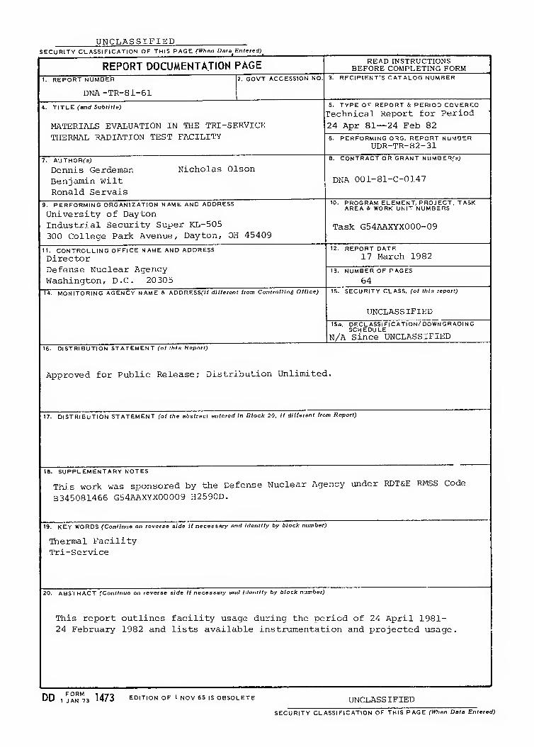
MATERIALS EVALUATION IN THE TRI-SERVICE THERMAL RADIATION TEST FACILITY
7. AUTHORCs;
Dennis Gerdeman Benjamin Wilt Ronald Servais
Nicholas Olson
9. PERFORMING ORGANIZATION NAME AND ADDRESS
University of Dayton Industrial Security Super KL-505 300 College Park Avenue, Dayton, OH 45409
READ INSTRUCTIONS BEFORE COMPLETING FORM
3. RECIPIENT'S CATALOG NUMBER
5. TYPE OF REPORT a PERIOD COVERED
Technical Report for Period 24 Apr 81—24 Feb 82 6. PERFORMING O^G. REPORT NUMBER
UDR-TR-82-31 8. CONTRACT OR GRANT NUMBERfsJ
DNA 001-81-C-0147
11. CONTROLLING OFFICE NAME AND ADDRESS
Director Defense Nuclear Agency Washington, D.C. 20 30 5
14. MONITORING AGENCY NAME & ADDRESSfif di//eren( from Controlling Office)
10. PROGRAM ELEMENT. PROJECT, TASK AREA a WORK UNIT NUMBERS
Task G54AAXYX000-09
12. REPORT DATE
17 March 1982
13. NUMBER OF PAGES
64 15. SECURITY CLASS, (of this report)
UNCLASSIFIED 15a. DECL ASSIFI CATION/DOWN GRADINC
SCHEDULE N/A since UNCLASSIFIED
16. DISTRIBUTION ST ATEMEN T Co/ f/i/s Repnrf)
Approved for Public Release; Distribution Unlimited.
17. DISTRIBUTION STATEMENT (of the abstract entered in Block 20, it different from Report)
18. SUPPLEMENTARY NOTES
This work was sponsored by the Defense Nuclear Agency under RDT&E RMSS Code
B345081466 G54AAXYX00009 H2590D.
19. KEY WORDS (Continue on reverse side if necessary and identify by block number)
Thermal Facility Tri-Service
20. ABSTRACT (Continue on reverse side If necessary and identify by block number)
This report outlines facility usage during the period of 24 April 1981- 24 February 1982 and lists available instrumentation and projected usage.
DD 1 JAN'73 1473 EDITION OF 1 NOV 65 IS OBSOLETE UNCLASSIFIED
SECURITY CLASSIFICATION OF THIS PAGE fWien Data Entered)
UNCLASSIFIED SECURITY CLASSIFICATION OF THIS PAGEfHTien Data Entered)
UNCLASSIFIED
SECURITY CLASSIFICATION OF TL.'-- PAGEfH'hon Dale Entered)
SUMMARY
The Tri-Service Thermal Radiation Test Facility, located
at Wright-Patterson Air Force Base, Ohio, has been utilized
to complete over 9,600 materials tests during a five-year
period under contract to the Defense Nuclear Agency. The
facility has the capability to provide intense radiant heating
in conjunction with either aerodynamic or mechanical tensile
and bending loading.
Approximately 2,000 of the total tests were conducted
during the current contract. Utilization of the facility for
a similar number of materials evaluations is anticipated during
a follow-on contract. Facility improvements in the area of
heat flux improvement and surface phenomena data are also
anticipated as scheduling allows.
PREFACE
This summary report covers work performed during the period
from 24 April 19 81 to 24 February 19 82 under Defense Nuclear
Agency Contract DNA001-81-C-0147. The work was administered
under the direction of Lt. Col. R. A. Flory, Contracting Offi-
cer's Representative on this contract. The contract represents
a follow-on effort to Defense Nuclear Agency Contract DNAOOl-80-
C-0128 under which the following reports were generated:
UDRI-TR-77-28, "Tri-Service Thermal Radiation Test Facility: Test Procedures Handbook," May 1977.
DNA 4488Z, "Tri-Service Thermal Flash Test Facility," Interim Summary Report, 29 March 1978.
DNA 4757F, "Tri-Service Thermal Flash Test Facility," Final Report for Period 6 August 1976- 31 October 1978, 30 November 1978.
DNA 5197F, "Tri-Service Thermal Flash Test Facility," Final Report for Period 15 December 1978-15 December 1979, 15 January 1980.
DNA 5650F, "Materials Evaluation in the Tri-Service Thermal Radiation Test Facility," Final Report for Period 25 January 1980-28 February 1981, 28 February 1981. |
The work was conducted under the general supervision of
Mr. Dennis Gerdeman and the Principal Investigator was Mr.
Benjamin H. Wilt. Dr. Ronald A. Servais acted as consultant
and the research technician was Mr. Nicholas J. Olson.
TABLE OF CONTENTS
SECTION PAGE
SUMMARY
PREFACE
LIST OF ILLUSTRATIONS
LIST OF TABLES
1 INTRODUCTION
1.1 BACKGROUND 1.2 OBJECTIVES
2 TRI-SERVICE THERMAL FLASH TEST FACILITY
2.1 OVERVIEW 2.2 NUCLEAR FLASH SIMULATION 2.3 AERODYNAMIC LOAD SIMULATION 2.4 DYNAMIC LOAD SIMULATION 2.5 MECHANICAL LOAD SIMULATION 2.6 INSTRUMENTATION 2.7 DATA ACQUISITION SYSTEM 2.8 CONTROL SYSTEM 2.9 COMPUTER MODELING
3 FACILITY UTILIZATION
3.1 TEST SCHEDULING 3.2 COMPLETED TEST PROGRAMS 3.3 PROJECTED TEST PROGRAMS
4 PROJECTED FACILITY DEVELOPMENT
4.1 FACILITY MAINTENANCE AND IMPROVEMENTS
REFERENCES
APPENDIX - THERMAL FLASH TESTS
1
2
4
5
7
7 7
8
8 8
12 15 19 19 23 23 23
27
27 27 28
33
33
35
37
LIST OF ILLUSTRATIONS
FIGURE PAGE
1 Tri-Service Thermal Radiation Test Facility 9
2 High Density Lamp Bank 11
3 Mobile Quartz Lamp Bank 11
4 Radiation Heat Flux vs. Distance From Lamp Bank 13
5 Wind Tunnel 14
6 Wind Tunnel 70 cm Test Section 14
7 70 cm Test Section Shutter 16
8 MTS Tensile Loading Device 17
9 Mechanical Loading-Tension 20
10 Mechanical Loading-Bending 20
11 Data Acquisition System 24
12 Console 26
13 Thermal Flash Laboratory Overview 26
LIST OF TABLES
TABLE
1 Quartz Lamp Bank Specifications
2 MTS Operating System Components
PAGE
10
18
3 Recommended Mechanical Loading Specimen Information ^.9
4 Available Instrumentation 21
5 Heat Flux Gage Specifications 22
6 X-Y Recorder Specifications 22
7 Data Acquisition System Components 25
8 Completed and Current Test Programs 29
9 Projected Test Programs 32
10 Table of Materials " "^ 45
h '■ : . \
R NK
SECTION 1
INTRODUCTION
1.1 BACKGROUND
The University of Dayton Research Institute (UDRI) has
been under contract to the Defense Nuclear Agency (DNA) since
1976 to operate the Tri-Services Thermal Radiation Facility
located at the Air Force Wright Aeronautical Laboratories
(AFWAL), Wright-Patterson Air Force Base, Dayton, Ohio. Efforts
in support of the DNA have included the development and operation
of appropriate laboratory equipment to simulate thermal, aero-
dynamic, tensile, and bending loads and combinations of these
loading conditions on materials of interest to the Tri-Service
community,
The data accumulated through materials exposure to the
combined thermal and aerodynamic or thermal and mechanical loads
in the thermal flash facility can be utilized to match material
performance with design criteria and as a data base for computer
modeling.
1.2 OBJECTIVES
The primary objectives of the research activity have
remained unchanged since the establishment of the test facility
in 1976. These objectives have served to establish a materials
data base from over 9,6 00 tests during that time and can be
summarized as follows:
(1) To continue to provide the Tri-Service community
with a quick-response intense radiation heating experimental
capability, including the effects of aerodynamic and mechanical
loads;
(2) To conduct tests for the Tri-Service community as
required; and
(3) To maintain, improve, and modify the test facility
between scheduled tests.
SECTION 2
TRI-SERVICE THERMAL FLASH TEST FACILITY
2.1 OVERVIEW
The original development of the Tri-Service Thermal
Flash Test Facility is described in Reference 1. The facility
has undergone numerous improvements to reflect the current
needs of the Tri-Service community. There are still four
basic experimental capabilities.
(1) Irradiation of test specimens using the Mobile
Quartz Lamp Bank (MQLB);
(2) Irradiation of test specimens in aerodynamic flow
using the Mobile Quartz Lamp Bank or the High Density Lamp
Bank (HDLB);
(3) Irradiation of test specimens under tensile or bending
mechanical creep frame loads using the MQLB; and
(4) Irradiation of test specimens under transient tensile/
compression loads using the MQLB.
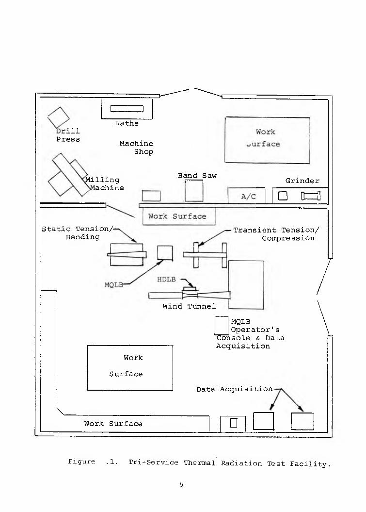
Available instrumentation include radiometers for deter-
mining heat flux, thermocouples for monitoring temperatures, a
pitot tube for determining flow velocities, still and movie
cameras, X-Y recorders, and various electronic control devices.
Limited machining facilities are available for minor specimen
modification or alteration during test programs. Figure 1
illustrates the facility layout.
2.2 NUCLEAR FLASH SIMULATION
The intense radiation needed to simulate a nuclear
flash can be produced by a series or bank of tungsten filament,
quartz lamps. Two banks of lamps are available in the Facility;
they are designated the High Density Lamp Bank (HDLB) and the
Mobile Quartz Lamp Bank (MQLB). The operational characteristics
of the banks are listed in Table 1; the banks are shown in
rill Press
Lathe
Machine Shop
Milling achine
Band Saw
Static Tension/ Bending
Grinder
D [t=3]
Transient Tension/ Compression
Wind Tunnel
Work
Surface
MQLB Operator's Console & Data Acquisition
Data Acquisition
Work Surface D
Figure .1. Tri-Service Thermal Radiation Test Facility.
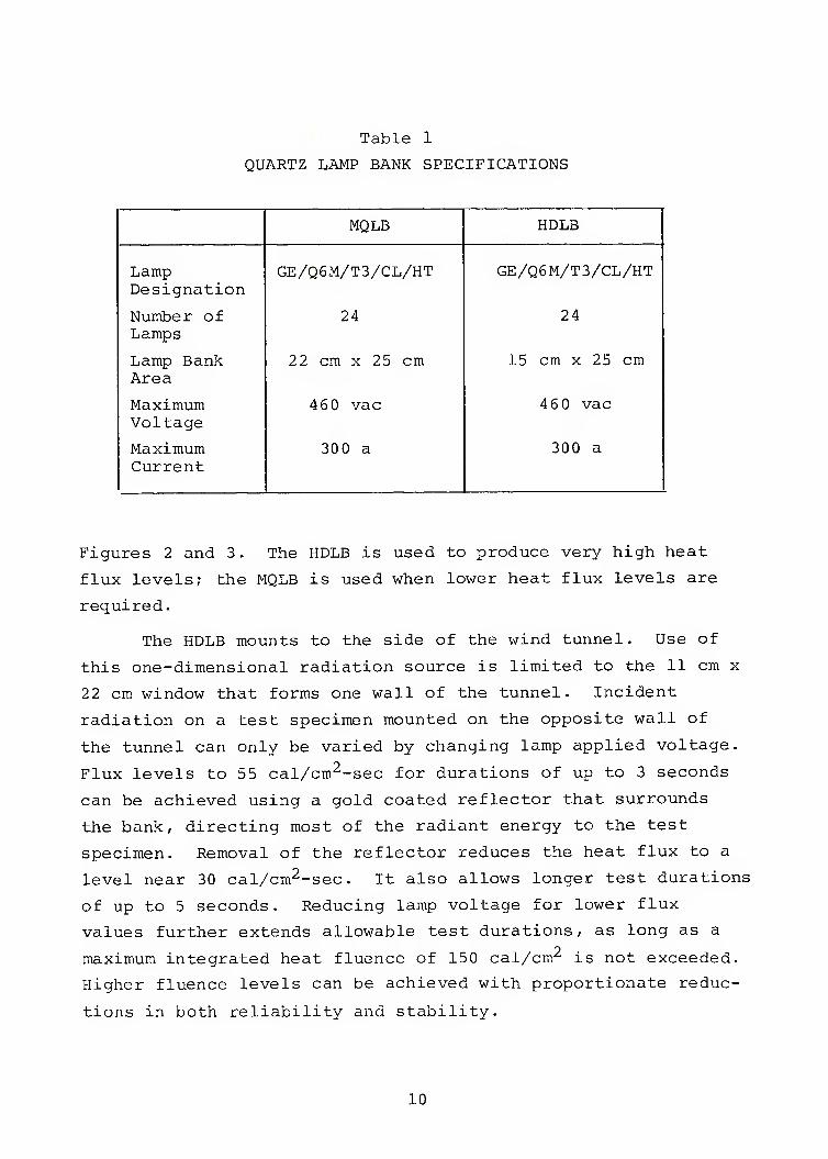
Table 1
QUARTZ LAMP BANK SPECIFICATIONS
MQLB HDLB
Lamp GE/Q6M/T3/CL/HT GE/Q6M/T3/CL/HT Designation
Number of 24 24 Lamps
Lamp Bank 22 cm X 25 cm 15 cm X 25 cm Area
Maximum 4 60 vac 46 0 vac Voltage
Maximum 300 a 300 a Current
Figures 2 and 3. The HDLB is used to produce very high heat
flux levels; the MQLB is used when lower heat flux levels are
required.
The HDLB mounts to the side of the wind tunnel. Use of
this one-dimensional radiation source is limited to the 11 cm x
22 cm window that forms one wall of the tunnel. Incident
radiation on a test specimen mounted on the opposite wall of
the tunnel can only be varied by changing lamp applied voltage.
Flux levels to 55 cal/cm^-sec for durations of up to 3 seconds
can be achieved using a gold coated reflector that surrounds
the bank, directing most of the radiant energy to the test
specimen. Removal of the reflector reduces the heat flux to a
level near 30 cal/cm^-sec. It also allows longer test durations
of up to 5 seconds. Reducing lamp voltage for lower flux
values further extends allowable test durations, as long as a
maximum integrated heat fluence of 150 cal/cm'^ is not exceeded.
Higher fluence levels can be achieved with proportionate reduc-
tions in both reliability and stability.
10
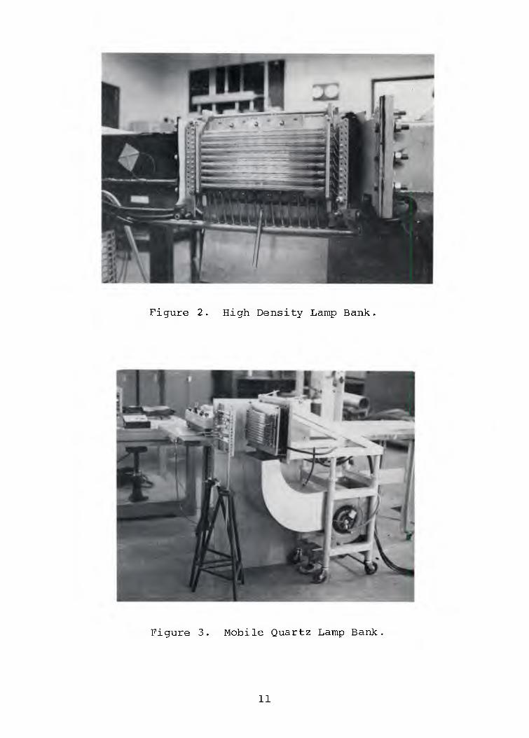
Figure 2. High Density Lamp Bank.
Figure 3. Mobile Quartz Lamp Bank
11
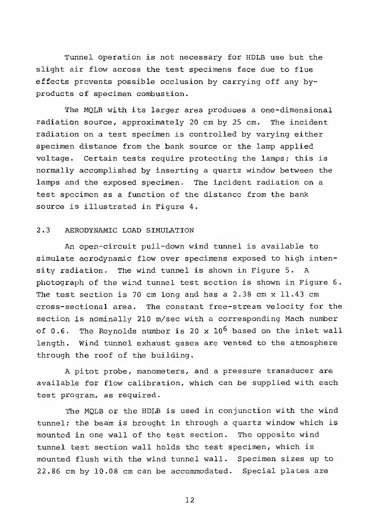
Tunnel operation is not necessary for HDLB use but the
slight air flow across the test specimens face due to flue
effects prevents possible occlusion by carrying off any by-
products of specimen combustion.
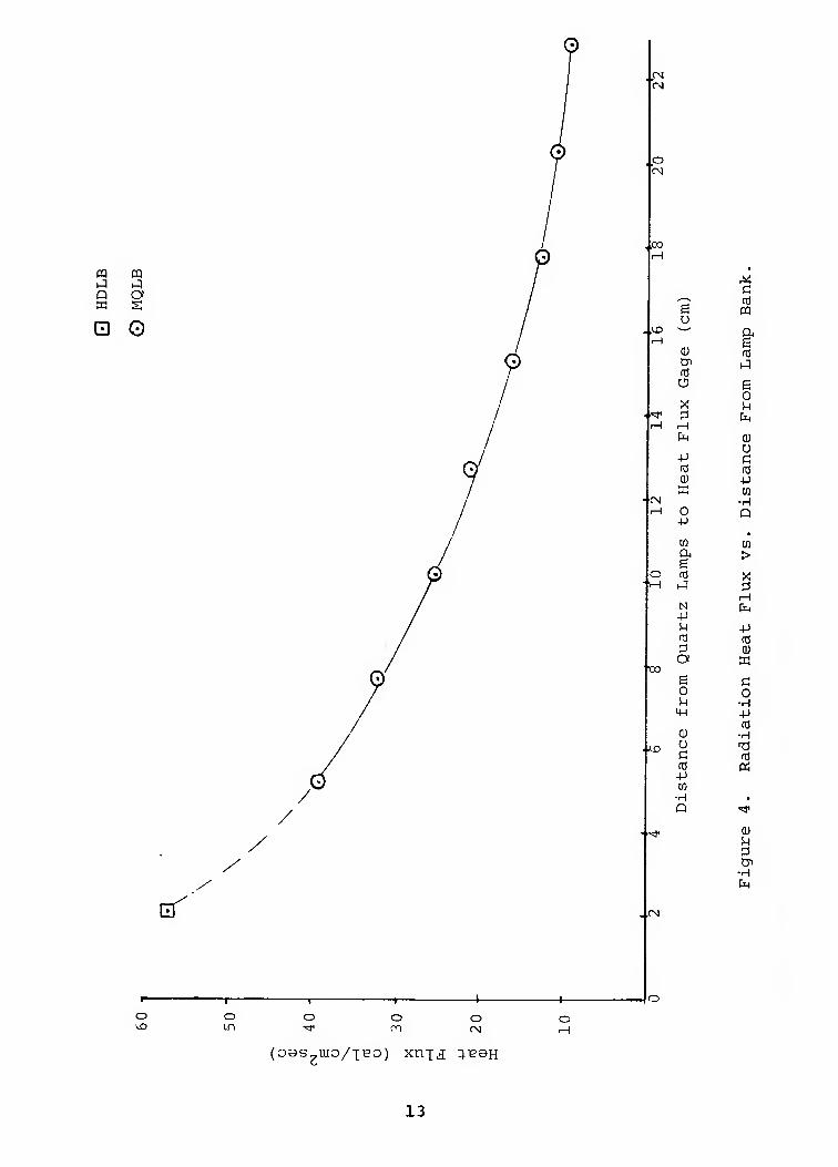
The MQLB with its larger area produces a one-dimensional
radiation source, approximately 20 cm by 25 cm. The incident
radiation on a test specimen is controlled by varying either
specimen distance from the bank source or the lamp applied
voltage. Certain tests require protecting the lamps; this is
normally accomplished by inserting a quartz window between the
lamps and the exposed specimen. The incident radiation on a
test specimen as a function of the distance from the bank
source is illustrated in Figure 4.
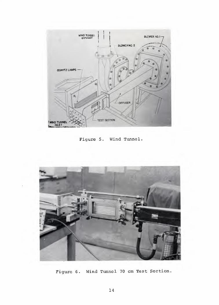
2.3 AERODYNAMIC LOAD SIMULATION
An open-circuit pull-down wind tunnel is available to
simulate aerodynamic flow over specimens exposed to high inten-
sity radiation. The wind tunnel is shown in Figure 5. A
photograph of the wind tunnel test section is shown in Figure 6.
The test section is 70 cm long and has a 2.38 cm x 11.43 cm
cross-sectional area. The constant free-stream velocity for the
section is nominally 210 m/sec with a corresponding Mach number
of 0.6. The Reynolds number is 20 x 10^ based on the inlet wall
length. Wind tunnel exhaust gases are vented to the atmosphere
through the roof of the building.
A pitot probe, manometers, and a pressure transducer are
available for flow calibration, which can be supplied with each
test program, as required.
The MQLB or the HDLB is used in conjunction with the wind
tunnel; the beam is brought in through a quartz window which is
mounted in one wall of the test section. The opposite wind
tunnel test section wall holds the test specimen, which is
mounted flush with the wind tunnel wall. Specimen sizes up to
22.86 cm by 10.08 cm can be accommodated. Special plates are
12
PQ m h^ 1^ Q o m s;
E O
rsi
.o CM
TO
.\D
-■CN
TO
cf ..CM
O
O O IT)
O O o
{oss^mo/j-eo) xnjji q-^BH
X G
^-^ n3 e pq o ^^ 04 e 0) (d Cr> j rC O g
0 X u :3 fa
(H fa 0)
o -p G (S (C 0) -P E to
■H 0 Q -p
CO •
CO a > e tri X ^A •^i
rH N fa +J !-l -P n3 td ;3 0) O ffi
S d o 0 i^ ■H m -P
(0 Q) •H O T3 G rO fd « -P tfi
■H • P "^
0) H :3 tn
-H fa
13
WIND lUfvht EXHAUn BLOWER NO I
BLOWER NO Z
QUARTZ LAMPS
WIND TUNNEL INLET
Figure 5. Wind Tunnel
Figure 6. Wind Tunnel 70 cm Test Section.
14
available for the test section for mounting the various calori-
meters and pitot tube for heat flux and flow calibration.
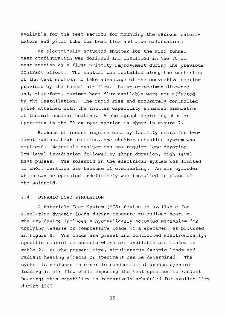
An electrically actuated shutter for the wind tunnel
test configuration was designed and installed in the 70 cm
test section as a first priority improvement during the previous
contract effort. The shutter was installed along the centerline
of the test section to take advantage of the convective cooling
provided by the tunnel air flow. Lamp-to-specimen distance
and, therefore, maximum heat flux available were not affected
by the installation. The rapid rise and accurately controlled
pulse attained with the shutter capability enhanced simulation
of thermal nuclear heating. A photograph depicting shutter
operation in the 70 cm test section is shown in Figure 7.
Because of recent requirements by facility users for two-
level radiant heat profiles, the shutter actuating system was
replaced. Materials evaluations now require long duration,
low-level irradiation followed by short duration, high level
heat pulses. The solenoid in the electrical system was limited
to short duration use because of overheating. An air cylinder
which can be operated indefinitely was installed in place of
the solenoid. i
i
2.4 DYNAMIC LOAD SIMULATION 1
A Materials Test System (MTS) device is available for •
simulating dynamic loads during exposure to radiant heating.
The MTS device includes a hydraulically actuated mechanism for
applying tensile or compressive loads to a specimen, as pictured
in Figure 8. The loads are preset and controlled electronically; [
specific control components which are available are listed in
Table 2. At the present time, simultaneous dynamic loads and
radient heating effects on specimens can be determined. The •
system is designed in order to conduct simultaneous dynamic
loading in air flow while exposing the test specimen to radiant
heating; this capability is tentatively scheduled for availability
during 1982.
15 i
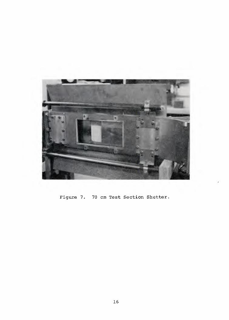
Figure 7. 70 cm Test Section Shutter,
16
Figure MTS Tensile Loading Device
17
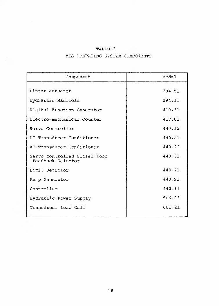
Table 2
MTS OPERATING SYSTEM COMPONENTS
Component Model
Linear Actuator 204.51
Hydraulic Manifold 294.11
Digital Function Generator 410.31
Electro-mechanical Counter 417.01
Servo Controller 440.13
DC Transducer Conditioner 440.21
AC Transducer Conditioner 440.22
Servo-controlled Closed Loop 440.31 Feedback Selector
Lim.it Detector 440.41
Ramp Generator 440.91
Controller 442.11
Hydraulic Power Supply 506 .03
Transducer Load Cell 661.21
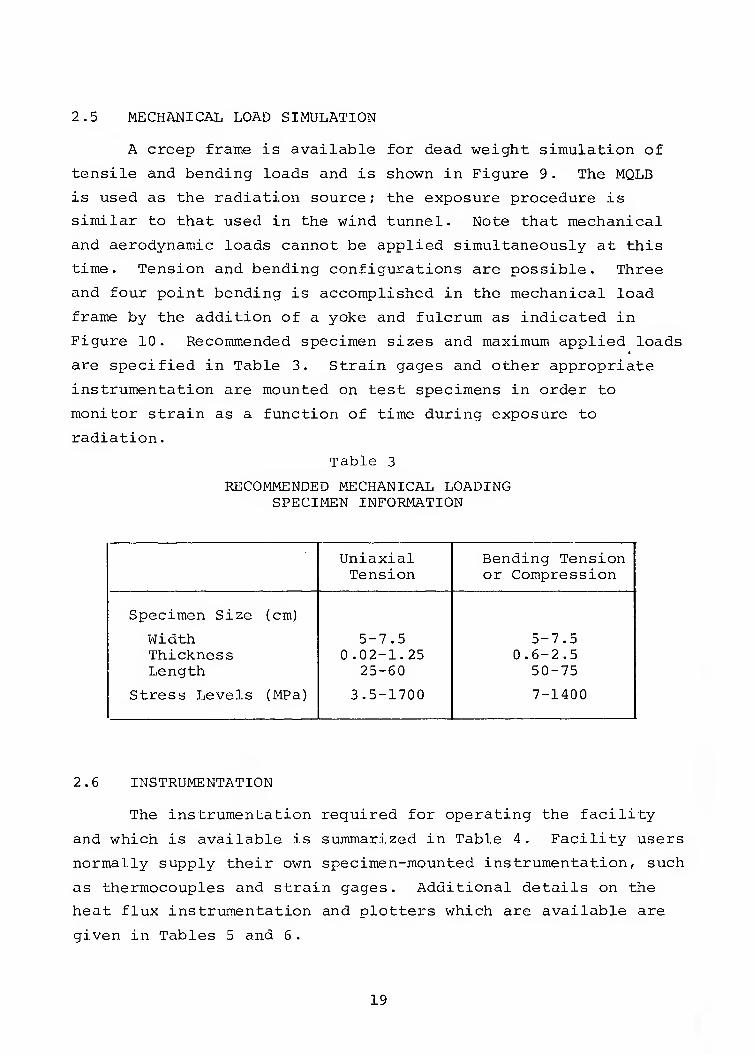
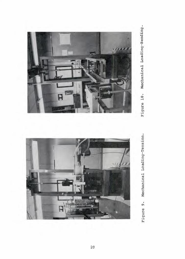
2.5 MECHANICAL LOAD SIMULATION
A creep frame is available for dead weight simulation of
tensile and bending loads and is shown in Figure 9. The MQLB
is used as the radiation source; the exposure procedure is
similar to that used in the wind tunnel. Note that mechanical
and aerodynamic loads cannot be applied simultaneously at this
time. Tension and bending configurations are possible. Three
and four point bending is accomplished in the mechanical load
frame by the addition of a yoke and fulcrum as indicated in
Figure 10. Recommended specimen sizes and maximum applied loads
are specified in Table 3. Strain gages and. other appropriate
instrumentation are mounted on test specimens in order to
monitor strain as a function of time during exposure to
radiation.
Table 3
RECOMMENDED MECHANICAL LOADING SPECIMEN INFORMATION
Uniaxial Bending Tension Tension or Compression
Specimen Size (cm)
Width 5-7.5 5-7.5 Thickness 0.02-1.25 0.6-2.5 Length 25-60 50-75
Stress Levels (MPa) 3.5-1700 7-1400
2.6 INSTRUMENTATION
The instrumentation required for operating the facility
and which is available is summarized in Table 4. Facility users
normally supply their own specimen-mounted instrumentation, such
as thermocouples and strain gages. Additional details on the
heat flux instrumentation and plotters which are available are
given in Tables 5 and 6.
19
•H
m I
-H 'O td O
H rc! O
■H
(d
o CD
O ■H
cn
0)
I Cn C
■H 13 n3 O 1^
fd u
■H
u
0) S-l ;3
•H
20
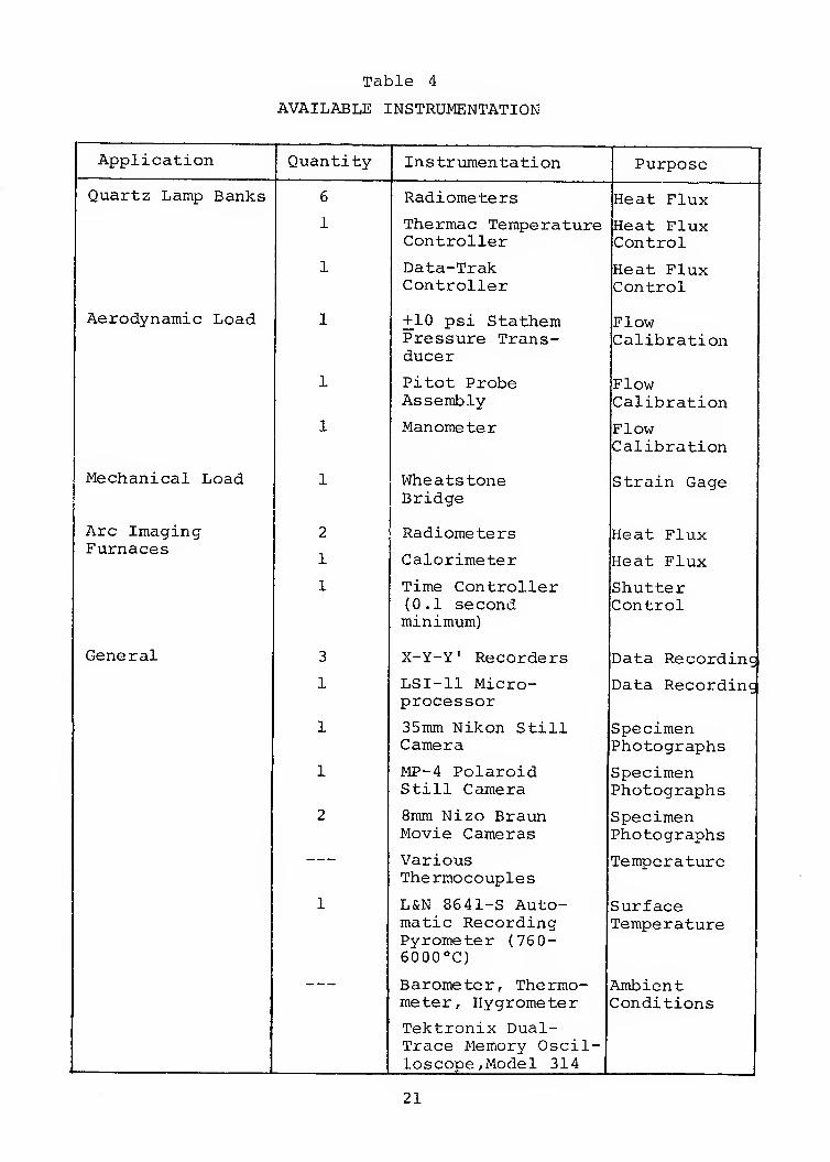
Table 4
AVAILABLE INSTRUMENTATION
Application
Quartz Lamp Banks
Aerodynamic Load
Mechanical Load
Arc Imaging Furnaces
Quantity
General
6
1
1
1
2
1
1
3
1
1
1
2
Instrumentation
Radiometers
Thermae Temperature Controller
Data-Trak Controller
+10 psi Stathem Pressure Trans- ducer
Pitot Probe Assembly
Manometer
Wheatstone Bridge
Radiometers
Calorimeter
Time Controller (0.1 second minimum)
X-Y-Y' Recorders
LSI-11 Micro- processor
35mm Nikon Still Camera
MP-4 Polaroid Still Camera
8mm Nizo Braun Movie Cameras
Various Thermocouples
L&N 8641-S Auto- matic Recording Pyrometer (76 0- 6000°C)
Barometer, Thermo- meter, Hygrometer
Tektronix Dual- Trace Memory Oscil- loscope,Model 314
Purpose
Heat Flux
Heat Flux Control
Heat Flux Control
Flow Calibration
Flow Calibration
Flow Calibration
Strain Gage
Heat Flux
Heat Flux
Shutter Control
Data Recordinc
Data Recordinc
Specimen Photographs
Specimen Photographs
Specimen Photographs
Temperature
Surface Temperature
Ambient Conditions
21
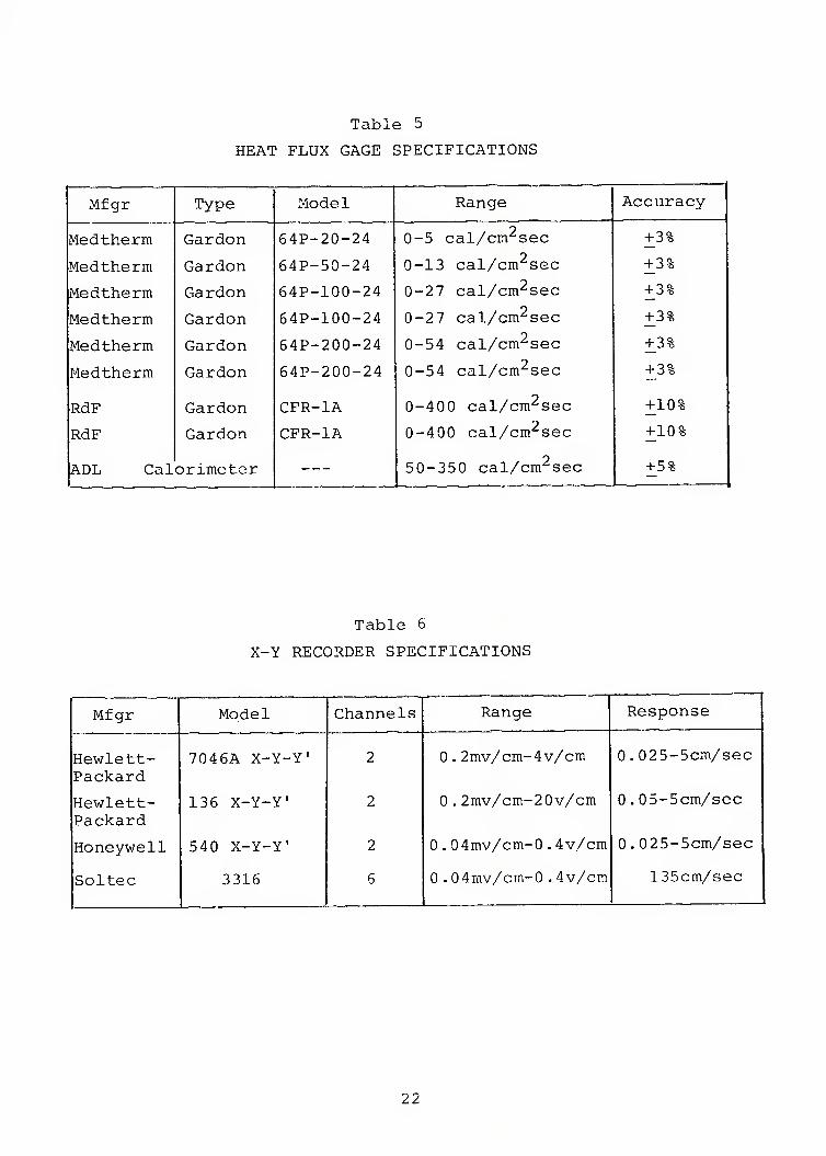
Table 5
HEAT FLUX GAGE SPECIFICATIONS
Mfgr Type Model Range Accuracy
Medtherm Garden 64P-20-24 0-5 cal/cm^sec + 3%
Medtherm Garden 64P-50-24 9-13 cal/cm^sec + 3%
Medtherm Garden 64P-100-24 0-27 cal/cm^sec + 3%
Medtherm Garden 64P-100-24 0-27 cal/cm^sec + 3%
Medtherm Garden 64P-200-24 0-54 cal/cm^sec + 3%
Medtherm Garden 64P-200-24 0-54 cal/cm^sec + 3%
RdF Garden CFR-IA 0-400 cal/cm^sec +10%
RdF Garden CFR-IA 0-400 cal/cm^sec +10%
ADL Cal erimeter 50-350 cal/cm^sec +5%
Table 6
X-Y RECORDER SPECIFICATIONS
Mfgr Model Channels Range Response
Hewlett- Packard
Hewlett- Packard
Honeywell
Soltec
7046A X~Y-Y'
136 X-Y-Y'
540 X-Y-Y'
3316
2
2
2
6
0.2mv/cm-4v/cm
0.2mv/cm~20v/cm
0.04mv/cm-0.4v/cm
0 .0 4rav/cm-0 .4v/cm
0. 025-5cm./sec
0.05-5cm/sec
0 . 025-5cm/sec
135cm/sec
22
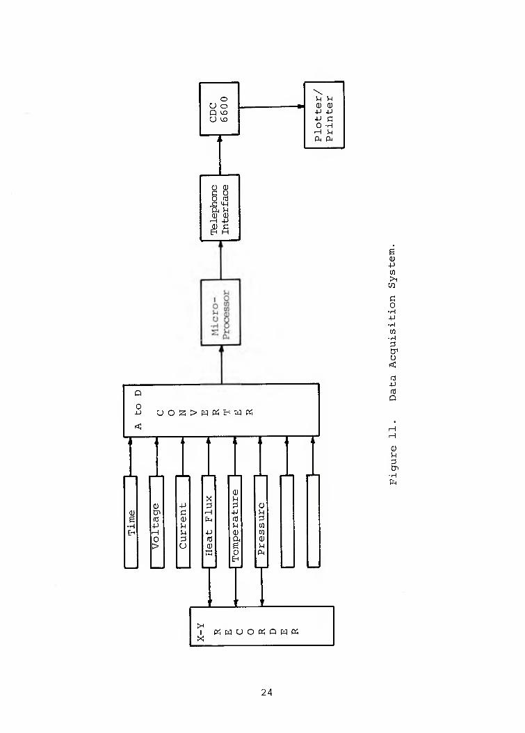
2.7 DATA ACQUISITION SYSTEM
The data acquisition system, including an LSI-11 micro-
computer, is capable of producing conventional X-Y plots on-line
or transmitting the digitized calibration or property data
directly to the Wright-Patterson Air Force Base (WPAFB) Computing
Facility for further data reduction. The output can be in the
form of tabulated or plotted and labelled data. Figure 11
schematically illustrates the system. Table 7 lists the system
components. The interface between the LSI-11 and the WPAFB
Computing Facility was developed by Lt. Randy Rushe and is
described in Reference 2.
2.8 CONTROL SYSTEM
The primary components of the laboratory (quartz lamp
banks, wind tunnel, exhaust system) can be controlled and
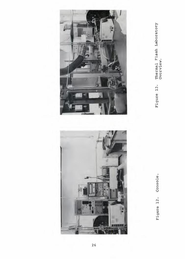
monitored from the operator console, which is shown in Figure 12.
Only one operator is required for most tests. The console is
located such that the operator can visually observe a test (if
appropriate) and also monitor critical voltages and currents,
etc. This allows the operator to abort a test if necessary.
The console also controls the microcomputer and the other
components of the data acquisition system with the exception
of the data terminal. Figure 13 is an overview of the mobile
quartz lamp bank, the wind tunnel, and the operating console.
2.9 COMPUTER MODELING
A two-dimensional thermal response computer program for
predicting the thermal response of materials exposed to intense
thermal radiation and aerodynamic cooling in the Tri-Service
Thermal Flash Test Facility was developed by William N. Lee
at Kaman AviDyne under contract to the Defense Nuclear Agency.
The analysis and operating procedures are described in detail
in Reference 3.
23
\ o
U O CD (D 4-) +J
U WD
Plo
t P
rin
t r: (1)
c u 0 to
JC 'U D-, U (U 0)
-H -P (D C tH H
Q
O
1 rtwUOtfQWO^
0) ■4-1
>i
c o
■H +J ■H to
■H
u
-p
Q
iH
0)
■H
24
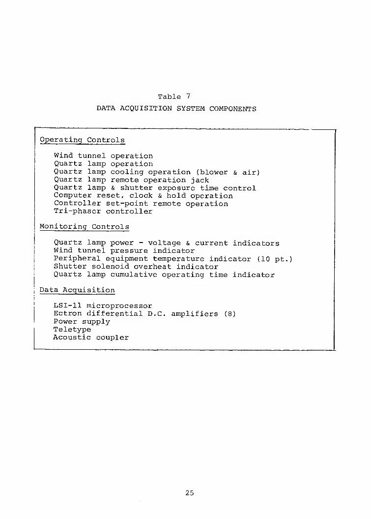
Table 7
DATA ACQUISITION SYSTEM COMPONENTS
Operating Controls
Wind tunnel operation Quartz lamp operation Quartz lamp cooling operation (blower & air) Quartz lamp remote operation jack Quartz lamp & shutter exposure time control Computer reset, clock & hold operation Controller set-point remote operation Tri-phaser controller
Monitoring Controls
Quartz lamp power - voltage & current indicators Wind tunnel pressure indicator Peripheral equipment temperature indicator (10 pt.) Shutter solenoid overheat indicator Quartz lamp cumulative operating time indicator
Data Acquisition
LSI-11 microprocessor Ectron differential D.C. amplifiers (8) Power supply Teletype Acoustic coupler
25
>1
o -p rd M O ,Q to
x; en ra
rH CU tO -rH g > S-i 1-1 0) 0)
j:^ > EH O
n
M
Cn -H fa
(U
o c o u
0)
■H
26
SECTION 3
FACILITY UTILIZATION
3.1 TEST SCHEDULING
The Tri-Services Nuclear Flash Test Facility is available
to governmental users on a no-charge basis. Test programs in-
volving nuclear thermal flash materials performance receive
priority although other tests may be accommodated; all test
programs must be approved by the Defense Nuclear Agency contract
monitor.
Specific details regarding test program procedures, sched-
uling, special testing requirements, specimen sizes, heat flux
levels, etc., should be directed to the Principal Investigator
and Test Director in charge of the Facility, Mr. Ben Wilt
(513-229-2517). Note that the analysis of material performance
must be conducted by the Facility user.
Material response tests for the Tri-Service community take
precedence over all other activities associated with the operation
of the Facility. That is, test requests have been scheduled at
the test initiator's convenience if possible. Since most test
programs are about one to five days in length, few conflicts
in scheduling have arisen and few are anticipated. Based on
experience, each new test program typically requires special
planning and hardware (such as instrumentation and specimen
mounting brackets); therefore, the more advance notice given
for a particular test program the more efficiently the tests
can be conducted. All test scheduling, special requirements,
etc., have been and will be handled by the Test Director, Mr.
Ben Wilt.
3.2 COMPLETED TEST PROGRAMS
The primary purpose of the Facility is to support the
Tri-Service community with a quick-response, thermal nuclear
flash, materials response testing capability. Tests which have
27
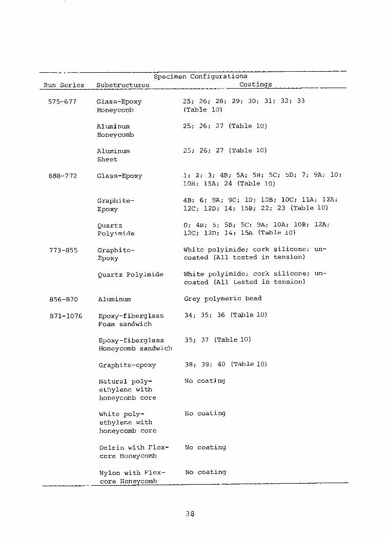
been conducted are summarized in Table 8. Additional informa-
tion on these tests can be obtained by contacting Mr. Ben VJilt
and References 4-8. The specific runs are listed in the Appendix.
3.3 PROJECTED TEST PROGRAMS
Table 9 identifies the known tests to be conducted during
the next 12 months. Since the primary purpose of the Facility
involves quick-response testing, it is not possible to establish
a comprehensive list of all future tests at this time.
28
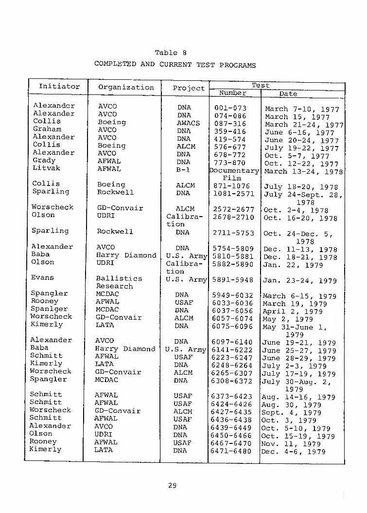
Table 8
COMPLETED AND CURRENT TEST PROGRAMS
Initiator Organization Project Test 1 Number Date
Alexander AVCO DNA 001-073 March 7-10, 1977 Alexander AVCO DNA 074-086 March 15, 19 7 7 Collis Boeing AWACS 087-316 March 21-24, 1977 Graham AVCO DNA 359-416 June 6-16, 1977 Alexander AVCO DNA 419-574 June 20-24, 1977 Collis Boeing ALCM 576-677 July 19-22, 1977 Alexander AVCO DNA 678-772 Oct. 5-7, 1977 Grady AFWAL DNA 773-870 Oct. 12-22, 1977 Litvak AFWAL B-1 Documentary
Film March 13-24, 1978
Collis Boeing ALCM 871-1076 July 18-20, 1978 Sparling Rockwell DNA 1081-2571 July 24-Sept. 28,
1978 Worscheck GD-Convair ALCM 2572-2677 Oct. 2-4, 1978 Olson UDRI Calibra-
tion 2678-2710 Oct. 16-20, 1978
Sparling Rockwell DNA 2711-5753 Oct. 24-Dec. 5, 1978
Alexander AVCO DNA 5754-5809 Dec. 11-13, 1978 Baba Harry Diamond U.S. Army 5810-5881 Dec. 18-21, 1978 Olson UDRI Calibra-
tion 5882-5890 Jan. 22, 1979
Evans Ballistics Research
U.S. Army 5891-5948 Jan. 23-24, 1979
Spangler MCDAC DNA 5949-6032 March 6-15, 1979 Rooney AFWAL USAF 6033-6036 March 19, 1979 Spanlger MCDAC DNA 6037-6056 April 2, 1979 Worscheck GD-Convair ALCM 6057-6074 May 2, 19 79 Kimerly LATA DNA 6075-6096 May 31-June 1,
1979 Alexander AVCO DNA 6097-6140 June 19-21, 1979 Baba Harry Diamond U.S. Army 6141-6222 June 25-27, 1979 Schmitt AFWAL USAF 6223-6247 June 28-29, 1979 Kimerly LATA DNA 6248-6264 July 2-3, 1979 Worscheck GD-Convair ALCM 6265-6307 July 17-19, 1979 Spangler MCDAC DNA 6308-6372 July 30-Aug, 2,
1979 Schmitt AFWAL USAF 6373-6423 Aug. 14-16, 1979 Schmitt AFWAL USAF 6424-6426 Aug. 30, 1979 Worscheck GD-Convair ALCM 6427-6435 Sept. 4, 1979 Schmitt AFWAL USAF 6436-6438 Oct. 3, 1979 Alexander AVCO DNA 6439-6449 Oct. 5-10, 1979 Olson UDRI DNA 6450-6466 Oct. 15-19, 1979 Rooney AFWAL USAF 6467-6470 Nov. 11, 1979 Kimerly LATA DNA 6471-6480 Dec. 4-6, 1979
29
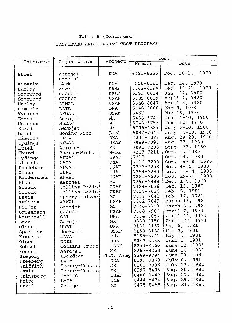
Table 8 (Continued)
COMPLETED AND CURRENT TEST PROGRAMS
Organization 1 \ ^-* -^^ -^ -'^ ^-^ A— Test
Initiator Project - Number Date
Etzel Aerojet- General
DNA 6481-6555 Dec. 10-13, 1979
Kimerly LATA DNA 6556-6561 Dec. 14, 1979 Hurley AFWAL USAF 6562-6598 Dec. 17-21, 1979 Sherwood CAAPCO USAF 6599-6634 Jan. 22, 1980 Sherwood CAAPCO USAF 6635-6639 April 2, 1980 Hurley AFWAL USAF 6640-6647 April 8, 1980 Kimerly LATA DNA 6648-6666 May 8, 19 80 Tydings AFWAL USAF 6467 May 13, 1980 Etzel Aerojet MX 6468-6742 June 4-10, 1980 Henders McDAC MX 6743-6755 June 12, 1980 Etzel Aerojet MX 6756-6881 July 7-10, 1980 Walsh Boeing-Wich. B-52 6882-7040 July 14-18, 1980 Kimerly LATA DNA 7041-7088 Aug. 20-23, 1980 Tydings AFWAL USAF 7089-7090 Aug. 27, 1980 Etzel Aerojet MX 7091-7206 Sept. 22, 1980 Church Boeing-Wich. B-52 7207-7211 Oct. 1, 1980 Tydings AFWAL USAF 7212 Oct. 14, 1980 Kimerly LATA DNA 7213-7232 Oct. 16-18, 1980 Rhodehamel AFWAL USAF 7233-7258 Nov. 4-10, 1980 Olson UDRI DNA 7259-7280 Nov. 11-14, 1980 Rhodehamel AFWAL USAF 7281-7295 Nov. 19-25, 1980 Etzel Aerojet MX 7296-7488 Dec. 1-5, 1980 Schuck Collins Radio USAF 7489-7626 Dec. 15, 1980 Schuck Collins Radio USAF 7627-7636 Feb. 5, 1981 Davis Sperry-Univac MX 7637-7641 Feb. 17, 1981 Tydings AFWAL USAF 7642-7645 March 16, 1981 Hender Aerojet MX 7646-7799 March 30, 19 81 Grinsberg CAAPCO USAF 7800-7903 April 7, 1981 McDonnell SAI DNA 7904-8057 April 20, 1981 Lane Aerojet MX 8058-8150 April 27, 1981 Olson UDRI DNA 8151-8157 May 6, 1981 Sparling Rockwell USAF 8158-8184 May 7, 1981 Kimerly LATA DNA 8185-8242 May 15, 1981 Olson UDRI DNA 8243-8253 June 1, 19 81 Schuck Collins Radio USAF 8254-8266 June 12, 1981 Hender Aerojet MX 8267-8268 June 16, 1981 Gregory Aberdeen U.S. Army 8269-8294 June 29, 19 81 Freeberg LATA DNA 8295-8360 July 6, 19 81 Griffith Sperry-Univac MX 8361-8396 July 13, 1981 Davis Sperry-Univac MX 8397-8405 Aug. 26, 1981
Grinsberg CAAPCO USAF 8406-8443 Aug. 27, 1981 Price LATA DNA 8444-8474 Aug. 29, 1981 Etzel Aerojet MX 8475-8658 Aug. 31, 1981
30
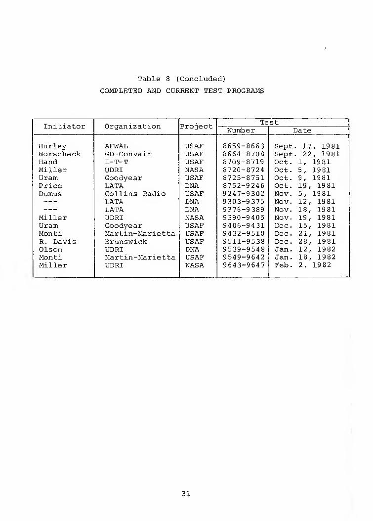
Table 8 (Concluded)
COMPLETED AND CURRENT TEST PROGRAMS
Initiator Organization Project Test Number Date
Hurley AFWAL USAF 8659-8663 Sept . 17, 1981 Worscheck GD-Convair USAF 8664-8708 Sept . 22, 1981 Hand I-T-T USAF 8709-8719 Oct. 1, 1981 Miller UDRI NASA 8720-8724 Oct. 5, 1981 Uram Goodyear USAF 8725-8751 Oct. 9, 1981 Price LATA DNA 8752-9246 Oct. 19, 1981 Dumus Collins Radio USAF 9247-9302 Nov. 5, 1981 LATA DNA 9303-9375 Nov. 12, 1981 LATA DNA 9376-9389 Nov. 18, 1981
Miller UDRI NASA 9390-9405 Nov. 19, 1981 Uram Goodyear USAF 9406-9431 Dec. 15, 1981 Monti Martin-Marietta USAF 9432-9510 Dec. 21, 1981 R. Davis Brunswick USAF 9511-9538 Dec. 28, 1981 Olson UDRI DNA 9539-9548 Jan. 12, 1982 Monti Martin-Marietta USAF 9549-9642 Jan. 18, 1982 Miller UDRI NASA 9643-9647 Feb. 2, 1982
31
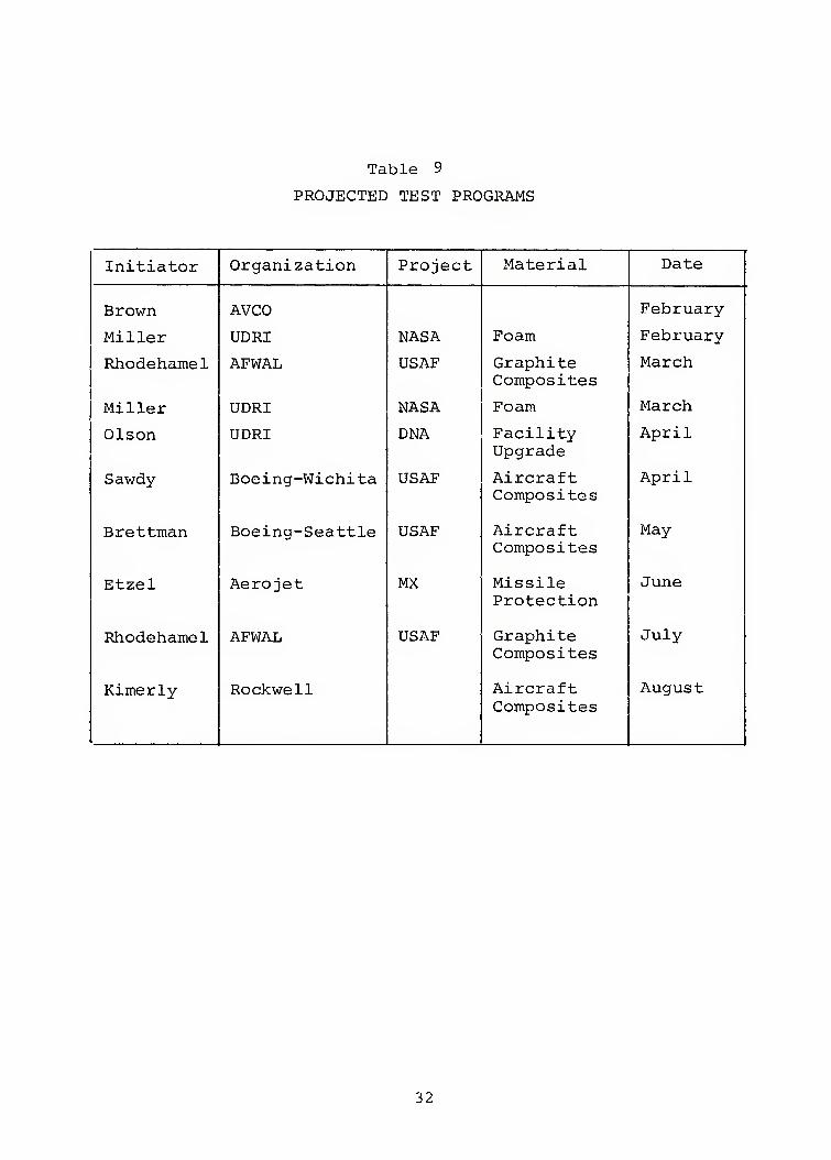
Table 9
PROJECTED TEST PROGRAMS
Initiator Organization Project Material Date
Brown AVCO February
Miller UDRI NASA Foam February
Rhodehamel AFWAL USAF Graphite Composites
March
Miller UDRI NASA Foam March
Olson UDRI DNA Facility Upgrade
April
Sawdy Boeing-Wichita USAF Aircraft Composites
April
Brettman Boeing-Seattle USAF Aircraft Composites
May
Etzel Aerojet MX Missile Protection
June
Rhodehamel AFWAL USAF Graphite Composites
July
Kimerly Rockwell Aircraft August Composites
32
SECTION 4
FACILITY DEVELOPMENT
4.1 FACILITY MAINTENANCE AND IMPROVEMENTS
Keeping the facility operational and current is an ongoing
activity which is carried out between scheduled tests. Experience
has shown that this effort requires about one week per month.
During the period between March 1981 and February 1982, approximately
34 weeks were devoted to the completion of a like number of test
programs for a total of over 2000 tests. The remaining time was
utilized to maintain the facility.
A review of various methods and devices currently available
to measure radiant heat flux has shown one device conforms to
most requirements of the TRTF. The calorimeter, manufactured by
HyCal, Inc., was purchased as the standard for facility calibra-
tion. Since the device is an asymptotic type gage, limitations
regarding response time do exist. The development of a radiometric
gage that can respond immediately to the energy imposed at the
leading edge of a square pulse is being pursued.
Facility capabilities were significantly extended with the
final incorporation of the hydraulically operated Mechanical Test
System (MTS) with the Quartz Lamp Bank. The sensitivity and
speed of the apparatus has greatly enhanced the combined thermal/
mechanical response of materials subjected to mechanical shock
during or immediately following a thermal pulse. The concept of
system portability has resulted in an easily movable test frame
designed to interface with both the wind tunnel and quartz lamps
for simultaneous thermal, mechanical and aerodynamic effects.
The ever broadening needs of users of the TRTF has led to
the design and fabrication of a number of specialized specimen
holders for the testing of unique shapes and configurations.
Special hardware was developed for applying uniform tensile loads
to braided shields surrounding fiber optics during thermal testing.
Special hardware was also developed to install cable bundles in a
3 3
repeatable location; to install short, thin specimens in a com-
pression test mode without initiating buckling of the specimens;
and for holding very thin metallic plates against the negative
pressure created by the wind tunnel.
One of the more significant improvements to the facility
included the fabrication of a highly polished water-cooled
reflector for the Mobile Quartz Lamp Bank. The improved cooling
combined with a new dual-pulse timing system with independent
lamp power and pulse width control enables long-term, low-level
radiant energy extending maximum fluence levels to 300 cal/cmi^.
The all solid-state timing system also incorporates the capability
for long-term low level specimen pre-heat followed instantly by
a high level short-term pulse. Independent and sequential pro-
gramming of such test parameters as wind tunnel operation, speci-
men exposure time, radiance levels and, to some extent, pulse
shaping is also possible.
Several improvements in data acquisition were incorporated
with the installation of the six-channel Soltec recorder. The
strip-chart recorder has a broad variety of ranges and provides
direct plots of temperature of up to six thermocouple inputs.
The extremely short duration pulses associated with
mechanical fracture of materials are now captured on the dual-
trace memory screen oscilloscope incorporated in the facility
during the contract period. The resulting traces are then photo-
graphed to provide a permanent record of material performance.
34
REFERENCES
1. Servais, R. A., Wilt, B, H., and Olson, N. J., "Tri- Service Thermal Flash Test Facility," Interim Summary Report, DNA 4488Z, 29 March 1978.
2. Rushe, R., "A Microcomputer Data Acquisition System for Materials Testing," Master of Science Thesis submitted to the Air Force Institute of Technology, March 1978.
3. Lee, W. N., "TRAP-ML-A Two Dimensional Thermal Response Code Tailored for the Defense Nuclear Agency Tri-Service Thermal Radiation Test Facility," DNA 4770F, 30 November 1978
4. Scherer, W. R. and Collis, S. E., "Nuclear Thermal Suviv- ability/Vulnerability of the E-4B," Boeing Aerospace Co. Rpt. No. D226-20380-1, March 1977.
5. "Skin Friction Drag Increase Due to Nuclear Thermal Damage," Boeing Aerospace Co. Final Report on Contract DNA001-77-C-0090, 30 September 1977. %
6. Collis, S. E., "Simulated Nuclear Thermal Testing of AGM-86 Honeycomb Sandwich Structures," Boeing Aerospace Co. Rpt. No. D232-10599-3, November 1977.
7. Alexander, J. G., "Conductive Coatings for Composite Aircraft Surfaces," AVCO Systems Division, Rpt. No. AFML-TR-77-164, September 1977.
8. Collis, S. E., "Simulated Nuclear Thermal Testing of AGM-86 Nosecap Sandwich Structure and Fin/Elevon Graphite- Epoxy Composites," Boeing Aerospace Co. Rpt. (to be published).
35

BLANK
36
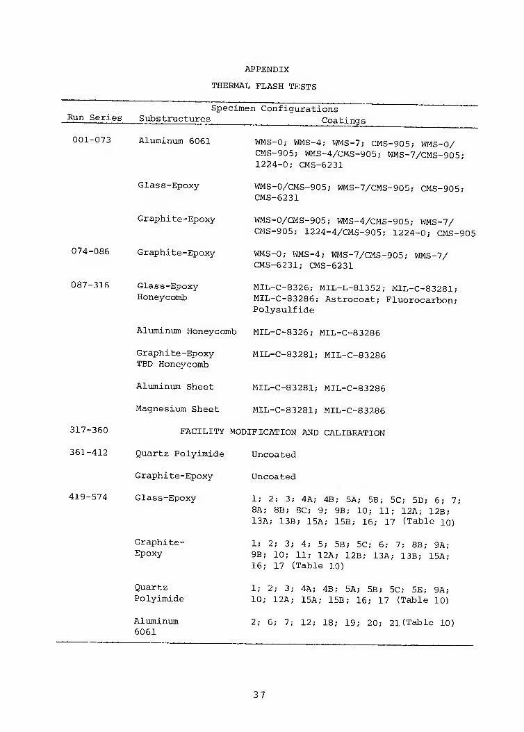
APPENDIX
THERMAL FLASH TESTS
Specimen Configurations Run Series Substructures Coatings
001-073
074-086
087-316
317-360
361-412
419-574
Aluminum 6061
Glass-Epoxy
Graphite-Epoxy
Graphite-Epoxy
Glass-Epoxy Honeycomb
WMS-0; WMS-4; WMS-7; CMS-905; WMS-0/ CMS-905; WMS-4/CMS-905; WMS-7/CMS-905; 1224-0; CMS-6231
WMS-O/CMS-905; WMS-7/CMS-905; CMS-905; CMS-6231
WMS-O/CMS-905; WMS-4/CMS-905; WMS-7/ CMS-905; 1224-4/CMS-905; 1224-0; CMS-905
WMS-0; WMS-4; WMS-7/CMS-905; WMS-7/ CMS-6231; CMS-6231
MIL-C-8326; MIL-L-81352; MIL-C-83281; MIL-C-83286; Astrocoat; Fluorocarbon; Polysulfide
Aluminum Honeycomb MIL-C-8326; MIL-C-83286
Graphite-Epoxy MIL-C-83281; MIL-C-83286 TBD Honevcomb
Aluminum Sheet
Magnesiiam Sheet
MIL-C-83281; MIL-C-83286
MIL-C-83281; MIL-C-83286
FACILITY MODIFICATION AND CALIBRATION
Quartz Polyimide Uncoated
Uncoated Graphite-Epoxy
Glass-Epoxy
Graphite- Epoxy
Quartz Polyimide
Aluminum 6061
1; 2; 3; 4A; 4B; 5A; 5B; 5C; 5D; 6; 7; 8A; 8B; 8C; 9; 9B; 10; 11; 12A; 12B; 13A; 13B; 15A; 15B; 16; 17 (Table lo)
1; 2; 3; 4; 5; 5B; 5C; 6; 7; 8B; 9A; 9B; 10; 11; 12A; 12B; 13A; 13B; 15A; 16; 17 (Table 10)
1; 2; 3; 4A; 4B; 5A; 5B; 5C; 5E; 9A; 10; 12A; 15A; 15B; 16; 17 (Table 10)
2; 6; 7; 12; 18; 19; 20; 21(Table 10)
37
Run Series
Specimen Configiarations Substructures Coatings
575-677 Glass-Epoxy Honeycomb
Aluminum Honeycomb
Aluminum Sheet
688-772 Glass-Epoxy
Graphite- Epoxy
Quartz Polyimide
773-855 Graphite- Epoxy
Quartz Polyimide
856-870 Aluminum
871-1076 Epoxy-fiberglass Foam sandwich
Epoxy-fiberglass Honeycomb sandwich
Graphite-epoxy
Natural poly- ethylene with honeycomb core
White poly- ethylene with honeycomb core
Delrin with Flex- core Honeycomb
Nylon with Flex- core Honeycomb
25; 26; 28; 29; 30; 31; 32; 33 (Table 10)
25; 26; 27 (Table 10)
25; 26; 27 (Table 10)
1; 2; 3; 4B; 5A; 5B; 50; 5D; 7; 9A; 10; lOB; 15A; 24 (Table 10)
4B; 6; 9A; 90; 10; lOB; 100; llA; 12A; 120; 12D; 14; 15B; 22; 23 (Table 10)
0; 4B; 5; 5B; 50; 9A; lOA; lOB; 12A; 120; 12D; 14; 15A (Table 10)
White polyimide; cork silicone; un- coated (All tested in tension)
White polyimide; cork silicone; un- coated (All tested in tension)
Grey polymeric bead
34; 35; 36 (Table 10)
35; 37 (Table 10)
38; 39; 40 (Table 10)
No coating
No coating
No coating
No coating
38
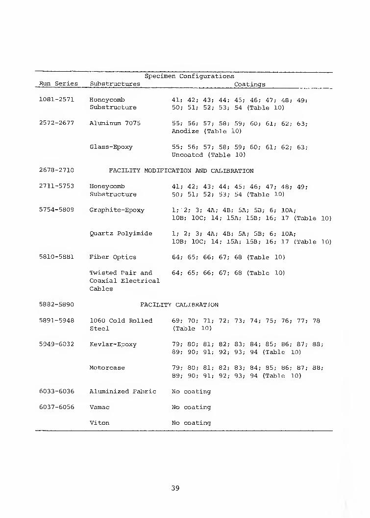
Run Series Specimen Configurations
Substructures Coatings
1081-2571
2572-2677
2678-2710
2711-5753
5754-5809
5882-5890
5891-5948
6033-6036
6037-6056
Honeycoinb Substructure
Al-uminum 7075
Glass-Epoxy
41; 42; 43; 44; 45; 46; 47; 48; 49; 50; 51; 52; 53; 54 (Table 10)
55; 56; 57; 58; 59; 60; 61; 62; 63; Anodize (Table 10)
55; 56; 57; 58; 59; 60; 61; 62; 63; Uncoated (Table 10)
FACILITY MODIFICATION AND CALIBRATION
Honeycoinb Substructure
Graphite-Epoxy
Quartz Polyimide
5810-5881 Fiber Optics
Twisted Pair and Coaxial Electrical Cables
41; 42; 43; 44; 45; 46; 47; 48; 49; 50; 51; 52; 53; 54 (Table 10)
1; 2; 3; 4A; 4B; 5A; 5B; 6; lOA; lOB; IOC; 14; 15A; 15B; 16; 17 (Table 10)
1; 2; 3; 4A; 4B; 5A; 5B; 6; lOA; lOB; IOC; 14; 15A; 15B; 16; 17 (Table 10)
64; 65; 66; 67; 68 (Table 10)
64; 65; 66; 67; 68 (Table 10)
FACILITY CALIBRATION
1060 Cold Rolled Steel
5949-6032 Kevlar-Epoxy
Motorcase
Aluminized Fabric
Vamac
Viton
69; 70; 71; 72; 73; 74; 75; 76; 77; 78 (Table 10)
79; 80; 81; 82; 83; 84; 85; 86; 87; 88; 89; 90; 91; 92; 93; 94 (Table 10)
79; 80; 81; 82; 83; 84; 85; 86; 87; 88; 89; 90; 91; 92; 93; 94 (Table 10)
No coating
No coating
No coating
39
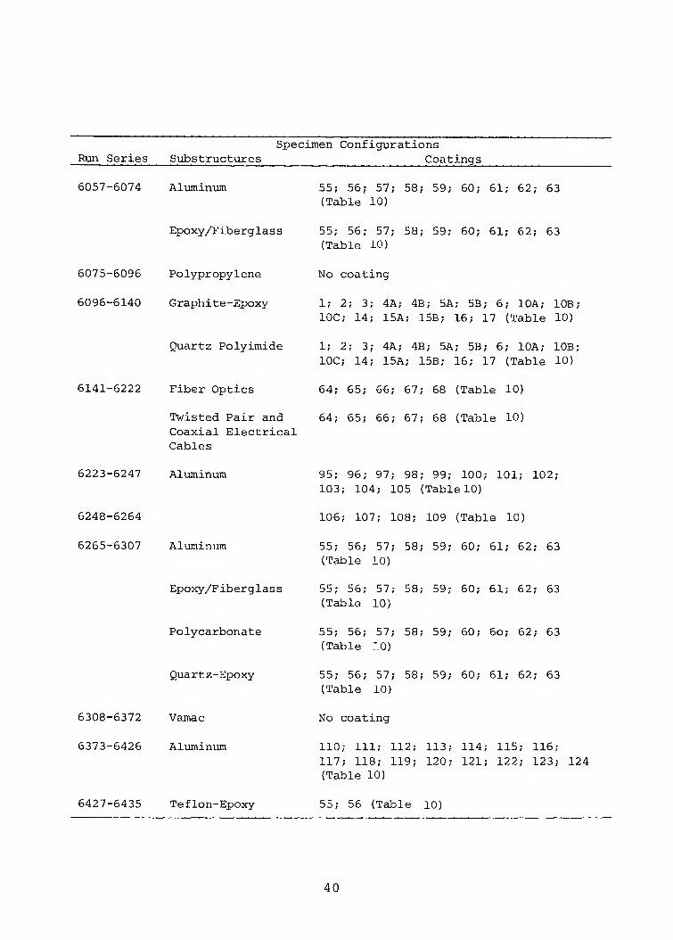
Specimen Configurations Run Series Substructures _^^ Coatings
6057-6074 Aluminum
Epoxy/Fiberglass
5075-5095 Polypropylene
6095-6140 Graphite-Epoxy
Quartz Polyimide
6141-6222 Fiber Optics
Twisted Pair and Coaxial Electrical Cables
6223-6247
6248-5254
5255-5307
6308-6372
6373-6426
Aluminum
Al'jminum
Epoxy/Fiberglass
Polycarbonate
Quartz-Epoxy
Vamac
Aluminum
6427-5435 Teflon-Epoxy
55; 55; 57; 58; 59; 60; 61; 62; 63 (Table 10)
55; 56; 57; 58; 59; 50; 51; 52; 63 (Table 10)
No coating
1; 2; 3; 4A; 4B; 5A; 5B; 5; lOA; lOB; IOC; 14; 15A; 15B; 15; 17 (Table 10)
1; 2; 3; 4A; 4B; 5A; 5B; 5; lOA; lOB; IOC; 14; 15A; 15B; 15; 17 (Table 10)
64; 65; 66; 67; 68 (Table 10)
54; 55; 55; 57; 58 (Table 10)
95; 95; 97; 98; 99; 100; 101; 102; 103; 104; 105 (Table 10)
106; 107; 108; 109 (Table 10)
55; 56; 57; 58; 59; 50; 61; 52; 53 (Table 10)
55; 56; 57; 58; 59; 50; 51; 62; 63 (Table 10)
55; 56; 57; 58; 59; 60; 6o; 62; 63 (Table 10)
55; 55; 57; 58; 59; 50; 61; 52; 53 (Table 10)
No coating
110; 111; 112; 113; 114; 115; 116; 117; 118; 119; 120; 121; 122; 123; 124 (Table 10)
55; 56 (Table 10)
40
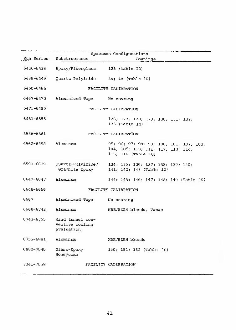
Run Series Specimen Configurations
Substructures Coatings
6436-6438
6439-6449
6450-6466
6467-6470
6471-6480
6481-6555
6556-6561
6562-6598
6599-6639
6640-6647
6648-6666
6667
6668-6742
6743-6755
6756-6881
6882-7040
7041-7058
Epoxy/Fiberglass 125 (Table 10)
Quartz Polyimide 4A; 4B (Table 10)
FACILITY CALIBRATION
Aluminized Tape No coating
FACILITY CALIBRATION
126; 127; 128; 129; 130; 131; 132; 133 (Table 10)
FACILITY CALIBRATION
Aluminum
Quartz-Polyimide/ Graphite Epoxy
Aluminum
95; 96; 97; 98; 99; 100; 101; 102; 103; 104; 105; 110; 111; 112; 113; 114; 115; 116 (Table 10)
134; 135; 136; 137; 138; 139; 140; 141; 142; 143 (Table 10)
144; 145; 146; 147; 148; 149 (Table 10)
FACILITY CALIBRATION
Aluminized Tape No coating
Aluminum NBR/EDPM blends, Vamac
Wind tunnel con- vective cooling evaluation
Aluminum
Glass-Epoxy Honeycomb
NBR/EDPM blends
150; 151; 152 (Table 10)
FACILITY CALIBRATION
41
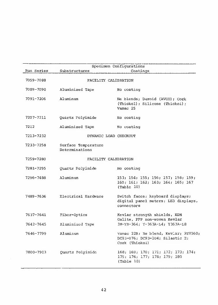
Run Series Specimen Configurations
Substructures Coatings
7059-7088
7089-7090
7091-7206
7207-7211
7212
7213-7232
7233-7258
7259-7280
7281-7295
7296-7488
7489-7636
7637-7641
7642-7645
7646-7799
7800-7903
FACILITY CALIBRATION
Aluminized Tape
Aluminum
Quartz Polyimide
Aluminized Tape
No coating
Ne blends; Duroid (AVCO); Cork (Thiokol); Silicone (Thiokol); Vamac 25
No coating
No coating
DYNAMIC LOAD CHECKOUT
Surface Temperature Determinations
FACILITY CALIBRATION
Quartz Polyimide
Aluminum
Electrical Hardware
Fiber-Optics
Aluminized Tape
Aluminum
Quartz Polyimide
No coating
153; 154; 155; 156; 157; 158; 159; 160; 161; 162; 163; 164; 165; 167 (Table 10)
Switch faces; keyboard displays; digital panel meters; LED displays, connectors
Kevlar strength shields, EDM Galite, PPP non-woven Kevlar 3M-YR-364; Y-363A-L4; Y363A-L8
Vamac 22B; Ne blend, Kevlar; RTV560; DC93-076; DC93-104; Silastic E; Cork (Thiokol)
168; 169; 170; 171; 172; 173; 174; 175; 176; 177; 178; 179; 180 (Table 10)
42
Run Series Specimen Configurations
S ub s true ture s Coatings
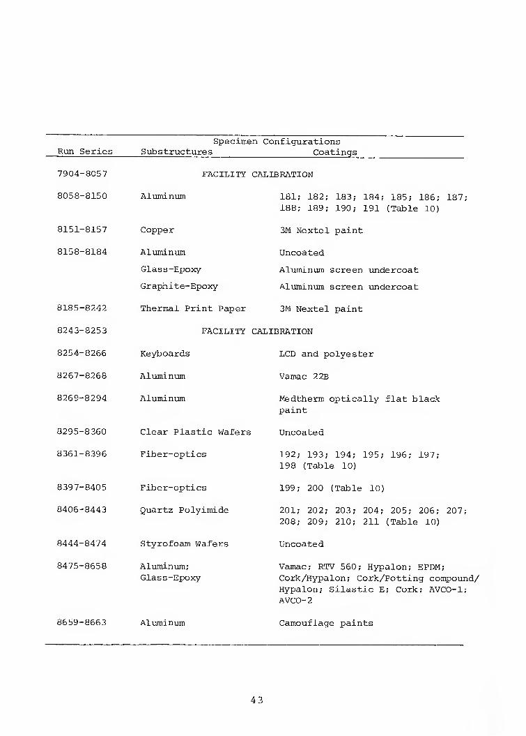
7904-8057
8058-8150
8151-8157
8158-8184
8185-8242
8243-8253
8254-8256
8267-8268
8269-8294
8295-8360
8361-8396
8397-8405
8406-8443
8444-8474
8475-8658
FACILITY CALIBRATION
Aluminum
Copper
Aluminum
Glass-Epoxy
Graphite-Epoxy
181; 182; 183; 184; 185; 186; 187; 188; 189; 190; 191 (Table 10)
3M Nextel paint
Uncoated
Aluminum screen undercoat
Aluminum screen ixndercoat
Thermal Print Paper 3M Nextel paint
FACILITY CALIBRATION
8659-8663
Keyboards
Aluminum
Aluminum
Clear Plastic Wafers
Fiber-optics
Fiber-optics
Quartz Polyimide
Styrofoam Wafers
Aluminum; Glass-Epoxy
Aluminum
LCD and polyester
Vamac 2 2B
Medtherm optically flat black paint
Uncoated
192; 193; 194; 195; 196; 197; 198 (Table 10)
199; 200 (Table 10)
201; 202; 203; 204; 205; 206; 207; 208; 209; 210; 211 (Table 10)
Uncoated
Vamac; RTV 560; Hypalon; EPDM; Cork/Hypalon; Cork/Potting compound/ Hypalon; Silastic E; Cork; AVCO-1; AVCO-2
Camouflage paints
4 3
Run Series Specimen Configurations
Substructures Coatings
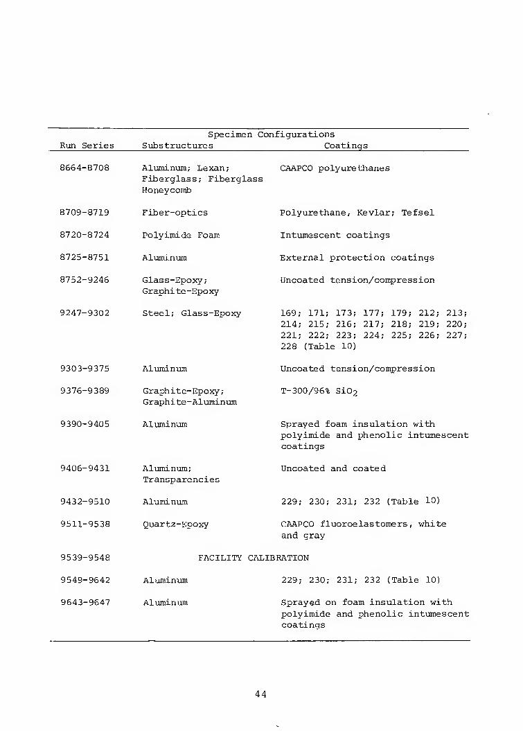
8664-8708
8709-8719
8720-8724
8725-8751
8752-9246
9247-9302
9303-9375
9376-9389
9390-9405
9406-9431
9432-9510
9511-9538
9539-9548
9549-9642
9643-9647
Aluminum; Lexan; CAAPCO polyurethanes Fiberglass; Fiberglass Honeycomb
Fiber-optics
Polyimide Foam
Aluminum
Glass-Epoxy; Graphi te-Epoxy
Steel; Glass-Epoxy
Aluminum
Graphite-Epoxy; Graphite-Aluminum
Aluminum
Aluminum; Transparencies
Aluminum
Quartz-Epoxy
Polyurethane, Kevlar; Tefsel
Intumescent coatings
External protection coatings
Uncoated tension/compression
169; 171; 173; 177; 179; 212; 213 214; 215; 216; 217; 218; 219; 220 221; 222; 223; 224; 225; 226; 227 228 (Table 10)
Uncoated tension/compression
T-300/96% Si02
Sprayed foam insulation with polyimide and phenolic intumescent coatings
Uncoated and coated
229; 230; 231; 232 (Table 10)
CAAPCO fluoroelastomers, white and gray
FACILITY CALIBRATION
Aluminum 229; 230; 231; 232 (Table 10)
Aluminiom Sprayed on foam insulation with polyimide and phenolic intumescent coatings
44
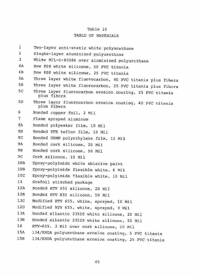
Table 10
TABLE OF MATERIALS
1 Two-layer anti-static white polyurethane
2 Single-layer aluminized polyurethane
3 White MIL-C-83286 over aluminized polyurethane
4A Dow 80 8 white silicone, 50 PVC titania
4B Dow 808 white silicone, 25 PVC titania
5A Three layer white fluorocarbon, 40 PVC titania plus fibers
5B Three layer white fluorocarbon, 25 PVC titania plus fibers
5C Three layer fluorocarbon erosion coating, 25 PVC titania plus fibers
5D Three layer fluorocarbon erosion coating, 40 PVC titania plus fibers
6 Bonded copper foil, 2 Mil
7 Flame sprayed aluminum
8A Bonded polyester film, 10 Mil
8B Bonded TFE teflon film, 10 Mil
8C Bonded UHMW polyethylene film, 10 Mil
9A Bonded cork silicone, 20 Mil
9B Bonded cork silicone, 50 Mil
9C Cork silicone, 10 Mil
lOA Epoxy-polyimide white ablative paint
lOB Epoxy-polyimide flexible white, 6 Mil
IOC Epoxy-polyimide flexible white, 10 Mil
11 Grafoil stitched package
12A Bonded RTV 655 silicone, 20 Mil
12B Bonded RTV 655 silicone, 50 Mil
12C Modified RTV 655, white, sprayed, 10 Mil
12D Modified RTV 655, white, sprayed, 3 Mil
13A Bonded silastic 23510 white silicone, 20 Mil
13B Bonded silastic 23510 white silicone, 50 Mil
14 RTV-655, 3 Mil over cork silicone, 10 Mil
15A 134/KHDA polyurethane erosion coating, 5 PVC titania
15B 134/KHDA polyurethane erosion coating, 25 PVC titania
45
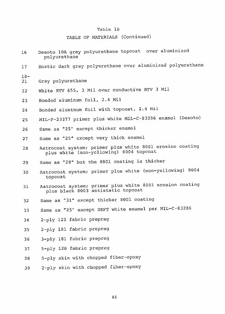
Table 10
TABLE OF MATERIALS (Continued)
16 Desoto lOA grey polyurethane topcoat over aluminized polyurethane
17 Bostic dark grey polyurethane over aluminized polyurethane
18- 21 Grey polyurethane
22 White RTV 655, 3 Mil over conductive RTV 3 Mil
23 Bonded aluminum foil, 2.4 Mil
24 Bonded aluminum foil with topcoat, 2.4 Mil
25 MIL-P-23377 primer plus white MIL-C-83286 enamel (Desoto)
26 Same as "25" except thicker enamel
27 Same as "25" except very thick enamel
28 Astrocoat system; primer plus white 8001 erosion coating plus white (non-yellowing) 8004 topcoat
29 Same as "28" but the 8001 coating is thicker
30 Astrocoat system; primer plus white (non-yellowing) 8004 topcoat
31 Astrocoat system; primer plus white 8001 erosion coating plus black 8003 antistatic topcoat
32 Same as "31" except thicker 8001 coating
33 Same as "25" except DEFT white enamel per MIL-C-83286
34 2-ply 120 fabric prepreg
35 2-ply 181 fabric prepreg
36 3-ply 181 fabric prepreg
37 5-ply 120 fabric prepreg
38 5-ply skin with chopped fiber-epoxy
39 2-ply skin with chopped fiber-epoxy
46
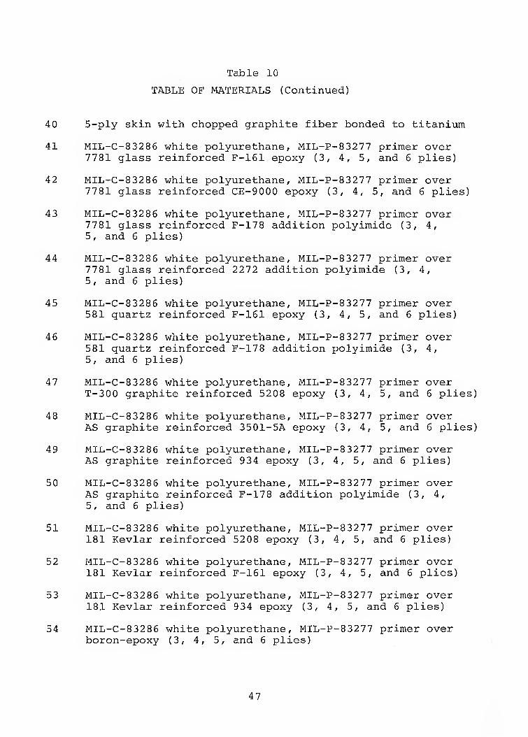
Table 10
TABLE OF MATERIALS (Continued)
40 5-ply skin with chopped graphite fiber bonded to titanium
41 MIL-C-83286 white polyurethane, MIL-P-83277 primer over 7781 glass reinforced F-161 epoxy (3, 4, 5, and 6 plies)
42 MIL-C-83286 white polyurethane, MIL-P-83277 primer over 7781 glass reinforced CE-9000 epoxy (3, 4, 5, and 6 plies)
43 MIL-C-83286 white polyurethane, MIL-P-83277 primer over 7781 glass reinforced F-178 addition polyimide (3, 4, 5, and 6 plies)
44 MIL-C-83286 white polyurethane, MIL-P-83277 primer over 7781 glass reinforced 2272 addition polyimide (3, 4, 5, and 6 plies)
45 MIL-C-83286 white polyurethane, MIL-P-83277 primer over 581 quartz reinforced F-161 epoxy (3, 4, 5, and 6 plies)
46 MIL-C-83286 white polyurethane, MIL-P-83277 primer over 581 quartz reinforced F-178 addition polyimide (3, 4, 5, and 6 plies)
47 MIL-C-83286 white polyurethane, MIL-P-83277 primer over T-300 graphite reinforced 5208 epoxy (3, 4, 5, and 6 plies)
48 MIL-C-83286 white polyurethane, MIL-P-83277 primer over AS graphite reinforced 3501-5A epoxy (3, 4, 5, and 6 plies)
49 MIL-C-83286 white polyurethane, MIL-P-83277 primer over AS graphite reinforced 934 epoxy (3, 4, 5, and 6 plies)
50 MIL-C-83286 white polyurethane, MIL-P-83277 primer over AS graphite reinforced F-178 addition polyimide (3, 4, 5, and 6 plies)
51 MIL-C-83286 white polyurethane, MIL-P-83277 primer over 181 Kevlar reinforced 5208 epoxy (3, 4, 5, and 6 plies)
52 MIL-C-83286 white polyurethane, MIL-P-83277 primer over 181 Kevlar reinforced F-161 epoxy (3, 4, 5, and 6 plies)
53 MIL-C-83286 white polyurethane, MIL-P-83277 primer over 181 Kevlar reinforced 934 epoxy (3, 4, 5, and 6 plies)
54 MIL-C-83286 white polyurethane, MIL-P-83277 primer over boron-epoxy (3, 4, 5, and 6 plies)
47
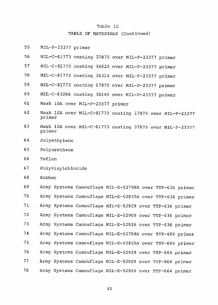
Table 10
TABLE OF MATERIALS (Continued)
55 MIL-P-23377 primer
56 MIL-C-81773 coating 37875 over MIL-P-23377 primer
57 MIL-C-81773 coating 36622 over MIL-P-23377 primer
58 MIL-C-81773 coating 36314 over MIL-P-23377 primer
59 MIL-C-81773 coating 17875 over MIL-P-23377 primer
60 MIL-C-83286 coating 30140 over MIL-P-23377 primer
61 Mask lOA over MIL-P-23377 primer
62 Mask lOA over MIL-C-81773 coating 17875 over MIL-P-23377 primer
63 Mask lOA over MIL-C-81773 coating 37875 over MIL-P-23377 primer
64 Polyethylene
65 Polyurethane
66 Teflon
67 Polyvinylchloride
68 Rubber
69 Army Systems Camouflage MIL-E-52798A over TTP-636 primer
70 Army Systems Camouflage MIL-E-52835A over TTP-636 primer
71 Army Systems Camouflage MIL-E-52929 over TTP-636 primer
72 Army Systems Camouflage MIL-E-52909 over TTP-636 primer
73 Army Systems Camouflage MIL-E-52926 over TTP-636 primer
74 Army Systems Camouflage MIL-E-52798A over TTP-664 primer
75 Army Systems Camouflage MIL-E-52835A over TTP-664 primer
76 Army Systems Camouflage MIL-E-52929 over TTP-664 primer
77 Army Systems Camouflage MIL-E-52909 over TTP-664 primer
78 Army Systems Camouflage MIL-E-52926 over TTP-664 primer
4 8
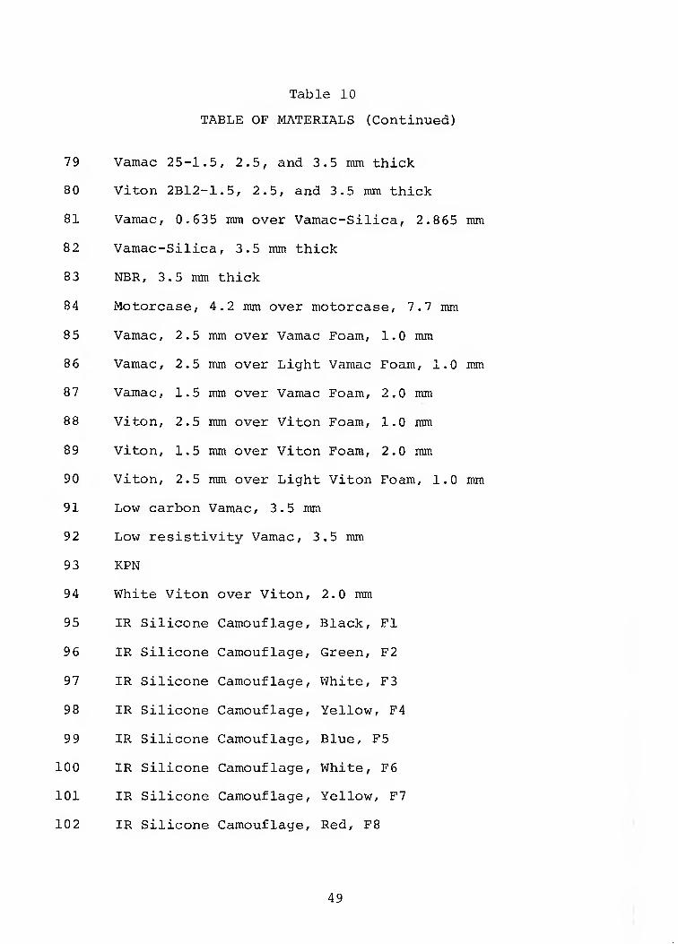
Table 10
TABLE OF MATERIALS (Continued)
7 9 Vamac 25-1.5, 2.5, and 3.5 mm thick
80 Viton 2B12-1.5, 2.5, and 3.5 mm thick
81 Vamac, 0.635 mm over Vamac-Silica, 2.865 mm
82 Vamac-Silica, 3.5 mm thick
83 NBR, 3.5 mm thick
84 Motorcase, 4.2 mm over motorcase, 7.7 mm
8 5 Vamac, 2.5 mm over Vamac Foam, 1.0 mm
8 6 Vamac, 2.5 mm over Light Vamac Foam, 1.0 mm
8 7 Vamac, 1.5 mm over Vamac Foam, 2,0 mm
88 Viton, 2.5 mm over Viton Foam, 1.0 ram
89 Viton, 1.5 mm over Viton Foam, 2.0 mm
90 Viton, 2.5 mm over Light Viton Foam, 1.0 mm
91 Low carbon Vamac, 3.5 mm
92 Low resistivity Vamac, 3,5 mm
93 KPN
94 White Viton over Viton, 2.0 mm
95 IR Silicone Camouflage, Black, Fl
96 IR Silicone Camouflage, Green, F2
97 IR Silicone Camouflage, White, F3
98 IR Silicone Camouflage, Yellow, F4
99 IR Silicone Camouflage, Blue, F5
100 IR Silicone Camouflage, White, F6
101 IR Silicone Camouflage, Yellow, F7
102 IR Silicone Camouflage, Red, F8
49
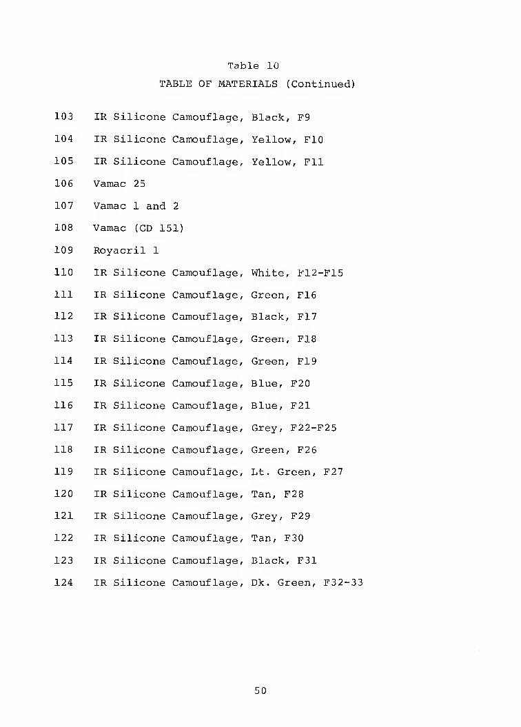
Table 10
TABLE OF MATERIALS (Continued)
103 IR Silicone Camouflage, Black, F9
104 IR Silicone Camouflage, Yellow, FlO
105 IR Silicone Camouflage, Yellow, Fll
106 Vamac 25
10 7 Vamac 1 and 2
108 Vamac (GD 151)
109 Royacril 1
110 IR Silicone Camouflage, White, F12-F15
111 IR Silicone Camouflage, Green, F16
112 IR Silicone Camouflage, Black, F17
113 IR Silicone Camouflage, Green, F18
114 IR Silicone Camouflage, Green, F19
115 IR Silicone Camouflage, Blue, F20
116 IR Silicone Camouflage, Blue, F21
117 IR Silicone Camouflage, Grey, F22-F25
118 IR Silicone Camouflage, Green, F26
119 IR Silicone Camouflage, Lt. Green, F27
120 IR Silicone Camouflage, Tan, F28
121 IR Silicone Camouflage, Grey, F29
122 IR Silicone Camouflage, Tan, F30
123 IR Silicone Camouflage, Black, F31
124 IR Silicone Camouflage, Dk. Green, F32-33
50
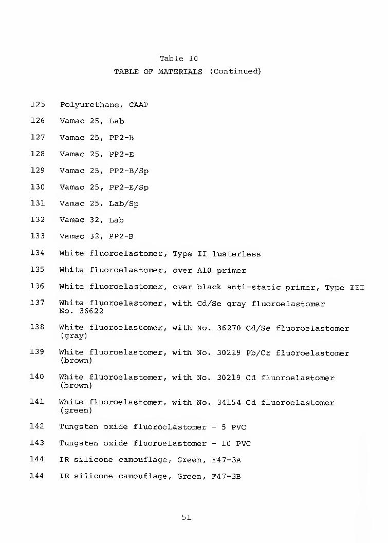
Table 10
TABLE OF MATERIALS (Continued)
125 Polyurethane, CAAP
126 Vamac 25, Lab
127 Vamac 25, PP2-B
128 Vamac 25, PP2-E
129 Vamac 25, PP2-B/Sp
130 Vamac 25, PP2-E/Sp
131 Vamac 25, Lab/Sp
132 Vamac 32, Lab
133 Vamac 32, PP2-B
134 White fluoroelastomer, Type II lusterless
135 White fluoroelastomer, over AlO primer
136 White fluoroelastomer, over black anti-static primer. Type III
137 White fluoroelastomer, with Cd/Se gray fluoroelastomer No. 36622
138 White fluoroelastomer, with No. 36270 Cd/Se fluoroelastomer (gray)
139 White fluoroelastomer, with No. 30219 Pb/Cr fluoroelastomer (brown)
140 White fluoroelastomer, with No. 30219 Cd fluoroelastomer (brown)
141 White fluoroelastomer, with No. 3415 4 Cd fluoroelastomer (green)
142 Tungsten oxide fluoroelastomer - 5 PVC
14 3 Tungsten oxide fluoroelastomer - 10 PVC
144 IR silicone camouflage. Green, F47-3A i
144 IR silicone camouflage. Green, F4 7-3B
51
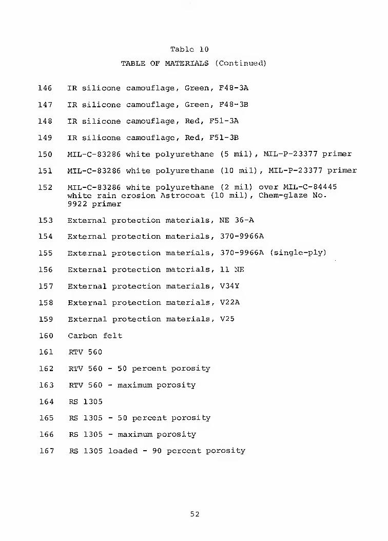
Table 10
TABLE OF MATERIALS (Continued)
146 IR silicone camouflage. Green, F48-3A
147 IR silicone camouflage, Green, F48-3B
148 IR silicone camouflage. Red, F51-3A
149 IR silicone camouflage. Red, F51-3B
150 MIL-C-83286 white polyurethane (5 mil), MIL-P-23377 primer
151 MIL-C-83286 white polyurethane (10 mil), MIL-P-23377 primer
152 MIL-C-83286 white polyurethane (2 mil) over MIL-C-84445 white rain erosion Astrocoat (10 mil), Chem-glaze No. 992 2 primer
15 3 External protection materials, NE 36-A
154 External protection materials, 370-9966A
155 External protection materials, 370-9966A (single-ply)
156 External protection materials, 11 NE
157 External protection materials, V34Y
158 External protection materials, V22A
159 External protection materials, V25
160 Carbon felt
161 RTV 560
162 RTV 560 - 50 percent porosity
16 3 RTV 560 - maximum porosity
164 RS 1305
165 RS 1305 - 50 percent porosity
166 RS 1305 - maximum porosity
167 RS 1305 loaded - 90 percent porosity
52
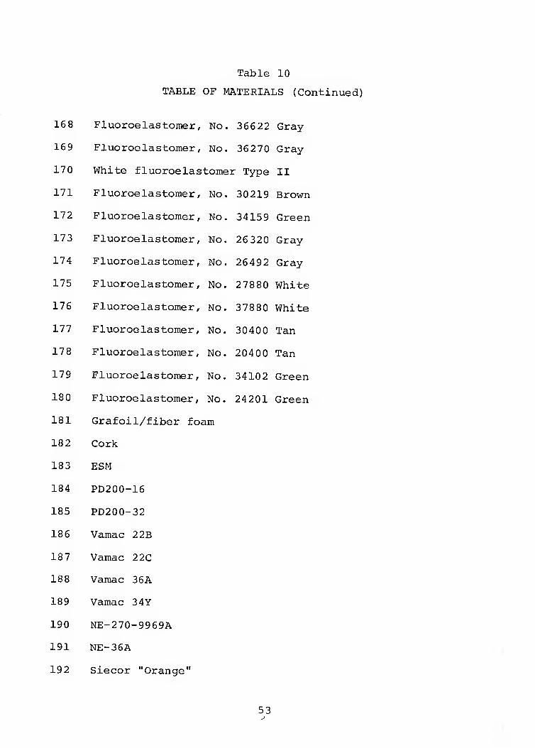
Table 10
TABLE OF MATERIALS (Continued)
168 Fluoroelastomer, No. 36622 Gray
169 Fluoroelastomer, No, 36270 Gray
170 White fluoroelastomer Type II
171 Fluoroelastomer, No. 30 219 Brown
172 Fluoroelastomer, No. 34159 Green
173 Fluoroelastomer, No. 26 320 Gray
174 Fluoroelastomer, No. 26492 Gray
175 Fluoroelastomer, No. 2 78 80 White
176 Fluoroelastomer, No. 378 80 White
177 Fluoroelastomer, No. 30400 Tan
178 Fluoroelastomer, No. 20400 Tan
179 Fluoroelastomer, No. 34102 Green
180 Fluoroelastomer, No. 24201 Green
181 Grafoil/fiber foam
18 2 Cork
18 3 ESM
184 PD200-16
185 PD200-32
186 Vamac 22B
18 7 Vamac 22C
188 Vamac 36A
189 Vamac 34Y
190 NE-270-9969A
191 NE-36A
192 Siecor "Orange"
53
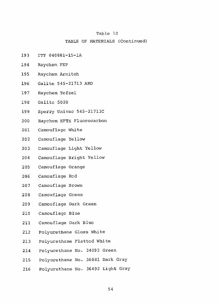
Table 10
TABLE OF MATERIALS (Continued)
193 ITT 040881-15-lA
194 Raychem FEP
195 Raychem Arnitch
196 Galite 545-21713 ARD
197 Raychem Tefzel
198 Galite 5020
199 Sperry Univac 545-21713C
2 00 Raychem EFTE Fluorocarbon
201 Camouflage White
202 Camouflage Yellow
203 Camouflage Light Yellow
204 Camouflage Bright Yellow
205 Camouflage Orange
206 Camouflage Red
207 Camouflage Brown
20 8 Camouflage Green
20 9 Camouflage Dark Green
210 Camouflage Blue
211 Camouflage Dark Blue
212 Polyurethane Gloss White
213 Polyurethane Flatted White
214 Polyurethane No, 34092 Green
215 Polyurethane No. 36081 Dark Gray
216 Polyurethane No. 36492 Light Gray
54
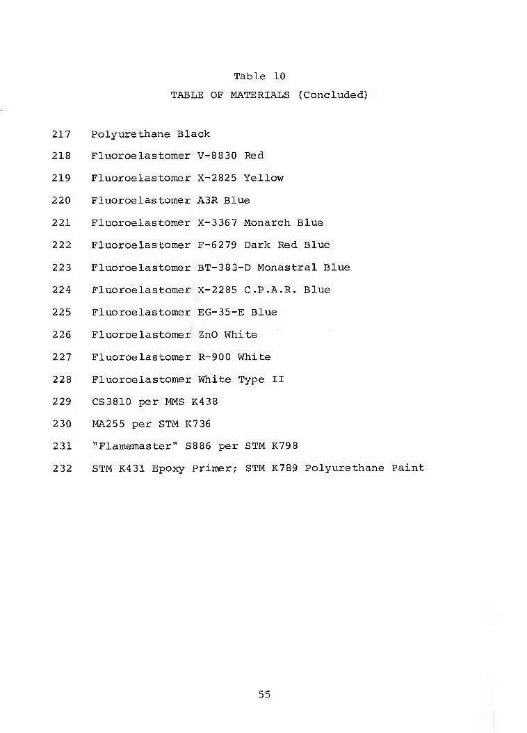
Table 10
TABLE OF MATERIALS (Concluded)
217 Polyurethane Black
218 Fluoroe la stonier V-8830 Red
219 Fluoroelastomer X-2825 Yellow
220 Fluoroelastomer A3R Blue
221 Fluoroelastomer X-3357 Monarch Blue
222 Fluoroelastomer F-6279 Dark Red Blue
223 Fluoroelastomer BT-383-D Monastral Blue
224 Fluoroelastomer X-2285 C.P.A.R. Blue
225 Fluoroelastomer EG-35-E Blue
226 Fluoroelastomer ZnO White
227 Fluoroelastomer R-900 White
228 Fluoroelastomer White Type II
229 CS3810 per MMS K438
230 MA255 per STM K736
231 "Flamemaster" S886 per STM K798
232 STM K431 Epoxy Primer; STM K789 Polyurethane Paint
55

! K
56
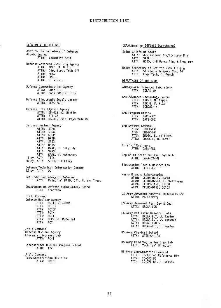
DISTRIBUTION LIST
DEPARTMENT OF DEFENSE
Asst to the Secretary of Defense Atomic Energy
ATTN: Executive Asst
Defense Advanced Rsch Proj Agency ATTN NMRO, G. Bulin ATTN Dir, Strat Tech Off ATTN NMRO ATTN PMO ATTN H. Winsor
Defense Communications Agency ATTN: Code 510 ATTN: Code 605, R. Lipp
Defense Electronic Supply Center ATTN: DEFC-ESA
Defense Intelligence Agency ATTN DB-4C2, C. Wiehle ATTN RTS-2A ATTN DB-4C, Rsch, Phys Vuln Br
Defense Nuc ear Agency ATTN STNA ATTN STRA ATTN STSP ATTN NATO ATTN SPSS ATTN NATA ATTN RAAE, H. Fitz, Jr ATTN SPAS ATTN RAAE, W. McKechney
4 cy ATTN TITL 10 cy ATTN SPTD, LTC Flory
Defense Technical Information Center 12 cy ATTN: DD
Dep Under Secretary of Defense ATTN: Principal DASD, C31, H. Van Trees
Department of Defense Explo Safety Board ATTN: Chairman
Field Comma Id Defense Nuc ear Agency
ATTN FCTT, W. Summa ATTN FCTEI ATTN FCTOF ATTN FCTX ATTN FCTT ATTN FCPR, J. McDaniel ATTN FCT
Field Command Defense Nuclear Agency Lawrence Livermore Lab
ATTN: FC-1
Interservice Nuclear Weapons School ATTN: TTV
Field Command Test Construction Division
ATTN: FCTC
DEPARTMENT OF DEFENSE (Continued)
Joint Chiefs of Staff ATTN ATTN ATTN
J-5 Nuclear Div/Strategy Div SAGA GD50, J-5 Force Ping & Prog Div
Under Secretary of Def for Rsch & Engrg ATTN: Strategic & Space Sys, OS ATTN: Engr Tech, J. Persh
DEPARTMENT OF THE ARMY
Atmospheric Sciences Laboratory ATTN: DELAS-EO
BMD Advanced Technology Center ATTN ATTN ATTN
ATC-T, M. Capps ATC-O, F. Hoke ICRDABH-X
BMD Program Office ATTN: DACS-BMT ATTN: DACS-BMZ
BMD Systems Command ATTN ATTN ATTN ATTN
BMDSC-HW BMDSC-NW BMDSC, E. Williams BMDSC-H, N. Hurst
Chief of Engineers ATTN: DAEN-RDL
Dep Ch of Staff for Rsch Dev & Acq ATTN: DAMA-CSM-N
Electronics Tech & Devices Lab ATTN: DELET-ER
Harry Diamond Laboratories ATTN ATTN ATTN ATTN
DELHD-NW-P, 20240 DELHD-NW-RA, L. Belliveau DELHD-TA-L, 81100 DELHD-DTSO, 00103
US Army Armament Material Readiness Cmd ATTN: MA Library
US Army Armament Rsch Dev & Cmd ATTN: DRDAR-LCW
US Army Ballistic Research Labs ATTN ATTN ATTN ATTN
DRDAR-BLT, W. Taylor DRDAR-BLT, W. Schuman DRDAR-TSB-S DRDAR-BLT, J. Keefer
US Army Chemical School ATTN: ATZN-CM-TPR
US Army Cold Region Res Engr Lab ATTN: Technical Director
US Army Communication Command ATTN ATTN ATTN
Technical Reference Div CC-OPS-PD CC-OPS-WR, R. Nelson
57
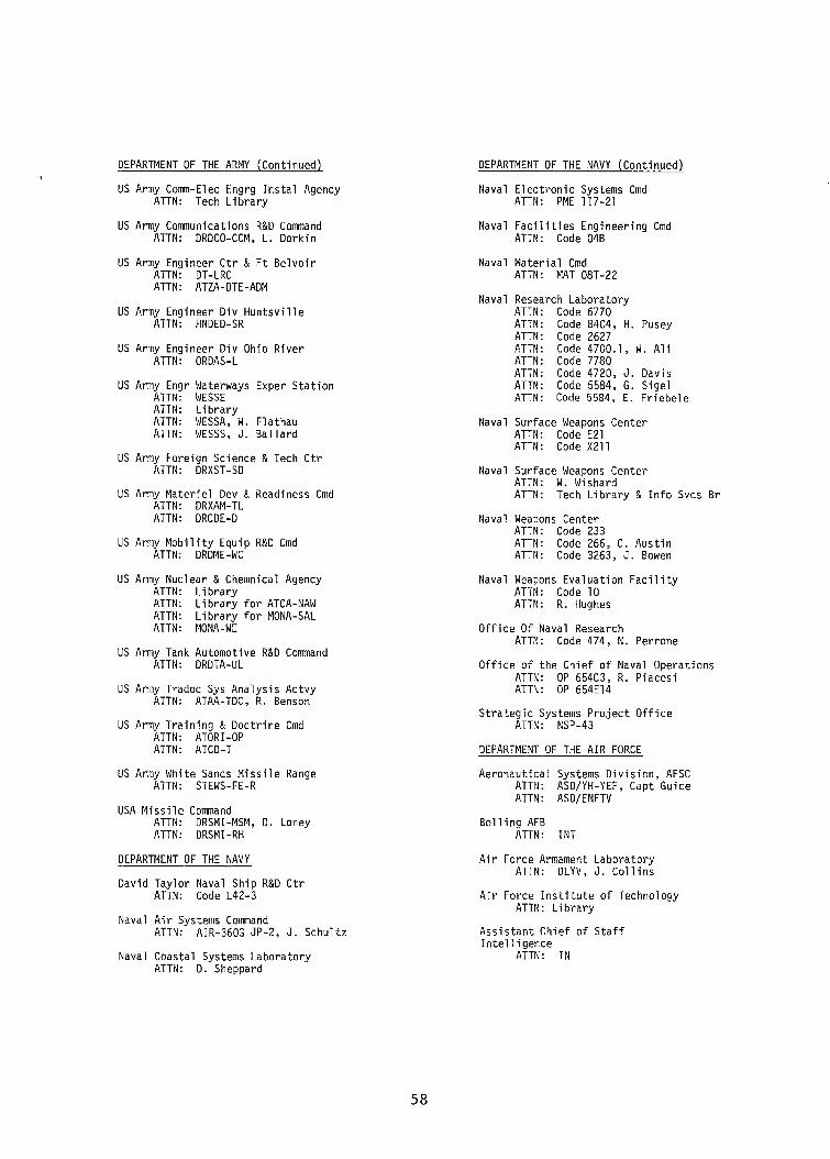
DEPARTMENT OF THE ARMY (Continued) DEPARTMENT OF THE NAVY (Continued)
US Army Comm-Elec Engrg Instal Agency ATTN: Tech Library
US Army Communications R&D Command ATTN: DRDCO-CCM, L. Dorkin
Naval Electronic Systems Cmd ATTN: PME 117-21
Naval Facilities Engineering Cmd ATTN: Code 04B
US Army Engineer Ctr & Ft Belvoir ATTN: DT-LRC ATTN: ATZA-DTE-ADM
US Army Engineer Div Huntsville ATTN: HNDED-SR
US Army Engineer Div Ohio River ATTN: ORDAS-L
US Army Engr Waterways Exper Station ATTN WESSE ATTN Library ATTN WESSA, W. Flathau ATTN WESSS, J. Ballard
US Army Foreign Science & Tech Ctr ATTN: DRXST-SD
US Army Materiel Dev & Readiness Cmd ATTN: DRXAM-TL ATTN: DRCDE-D
US Army Mobility Equip R&D Cmd ATTN: DRDME-WC
Naval Material Cmd ATTN: MAT 08T-22
Naval Research Laboratory ATTN ATTN ATTN ATTN ATTN ATTN ATTN ATTN
Code 6770 Code 8404, H. Pusey Code 2627 Code 4700.1, W. Al i Code 7780 Code 4720, J. Davis Code 5584, G. Sigel Code 5584, E. Friebele
Naval Surface Weapons Center ATTN: Code E21 ATTN: Code X211
Naval Surface Weapons Center ATTN: W. Wishard ATTN: Tech Library & Info Svcs Br
Naval Weapons Center ATTN ATTN ATTN
Code 233 Code 266, C. Austin Code 3263, J. Bowen
US Army Nuclear & Chemnical Agency ATTN Library ATTN Library for ATCA-NAW ATTN Library for MONA-SAL ATTN MONA-WE
US Army Tank Automotive R&D Command ATTN: DRDTA-UL
US Army Tradoc Sys Analysis Actvy ATTN: ATAA-TDC, R. Benson
US Army Training & Doctrine Cmd ATTN: ATORI-OP ATTN: ATCD-T
Naval Weapons Evaluation Facility ATTN: Code 10 ATTN: R. Hughes
Office Of Naval Research ATTN: Code 474, N. Perrone
Office of the Chief of Naval Operations ATTN: OP 654C3, R. Piacesi ATTN: OP 654E14
Strategic Systems Project Office ATTN: NSP-43
DEPARTMENT OF THE AIR FORCE
US Army White Sands Missile Range ATTN: STEWS-FE-R
USA Missile Command ATTN: DRSMI-MSM, D. Loney ATTN: DRSMI-RH
Aeronautical Systems Division, AFSC ATTN: ASD/YH-YEF, Capt Guice ATTN: ASD/ENFTV
Boiling AFB ATTN: INT
DEPARTMENT OF THE NAVY
David Taylor Naval Ship R&D Ctr ATTN: Code L42-3
Naval Air Systems Command ATTN: AIR-360G JP-2, J. Schultz
Naval Coastal Systems Laboratory ATTN: D. Sheppard
Air Force Armament Laboratory ATTN: DLYV, J. Collins
Air Force Institute of Technology ATTN: Library
Assistant Chief of Staff Intel 1igence
ATTN: IN
58
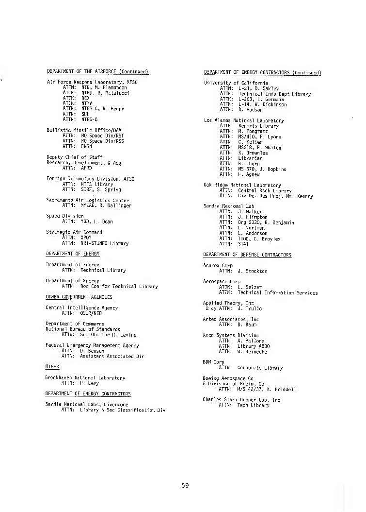
DEPARTMENT OF THE AIRFORCE (Continued)
Air Force Weapons Laboratory, AFSC ATTN NTE, M. Plamondon ATTN NTED, R. Matalucci ATTN DEX ATTN NTYV ATTN NTES-C, R. Henny ATTN SUL ATTN NTES-G
Ballistic ^ lissile Office/DAA ATTN HQ Space Div/RST ATTN HQ Space Div/RSS ATTN ENSN
Deputy Chi« ̂f of Staff Research, [ evelopment, & Acq
ATTN AFRD
Foreign Technology Division, AFSC ATTN: NIIS Library ATTN: SDBF, S. Spring
Sacramento Air Logistics Center ATTN: MMEAE, R. Dal linger
Space Division ATTN: YGD, L. Doan
Strategic Air Command ATTN: XPQM ATTN: NRI-STINFO Library
DEPARTMENT OF ENERGY
Department of Energy ATTN: Technical Library
DEPARTMENT OF ENERGY CONTRACTORS (Continued)
University of California ATTN L-21, D. Oakley ATTN Technical Info Dept Library ATTN L-203, L. Germain ATTN L-14, W. Dickinson ATTN B. Hudson
Los Alamos National Laboratory ATTN Reports Library ATTN M. Pongratz ATTN MS/410, P. Lyons ATTN C. Keller ATTN MS218, P. Whalen ATTN R. Brownlee ATTN Librarian ATTN R. Thorn ATTN MS 670, J. Hopkins ATTN H. Agnew
Oak Ridge National Laboratory ATTN: Central Rsch Library ATTN: Civ Def Res Proj, Mr. Kearny
Sandia National Lab ATTN J. Walker ATTN J. Plimpton ATTN Org 2330, B. Benjamin ATTN L. Vortman ATTN L. Anderson ATTN 1100, C. Broyles ATTN 3141
DEPARTMENT OF DEFENSE CONTRACTORS
Acurex Corp ATTN: J. Stockton
Department of Energy ATTN: Doc Con for Technical Library
OTHER GOVERNMENT AGENCIES
Central Intelligence Agency ATTN: OSWR/NED
Department of Commerce National Bureau of Standards
ATTN: Sec Ofc for R. Levine
Federal Emergency Management Agency ATTN: D. Bensen ATTN: Assistant Associated Dir
OTHER
Brookhaven National Laboratory ATTN: P. Levy
DEPARTMENT OF ENERGY CONTRACTORS
Sandia National Labs, Livermore ATTN: Library & Sec Classification Div
Aerospace Corp ATTN: L. Selzer ATTN: Technical Information Services
Applied Theory, Inc 2 cy ATTN: J. Trulio
Artec Associates, Inc ATTN: D. Baum
Avco Systems Division ATTN ATTN ATTN
A. Pallone Library A830 W. Reinecke
BDM Corp ATTN: Corporate Library
Boeing Aerospace Co A Division of Boeing Co
ATTN: M/S 42/37, K. Friddell
Charles Stark Draper Lab, Inc ATTN: Tech Library
59
DEPARTMENT OF DEFENSE CONTRACTORS (Continued) DEPARTMENT OF DEFENSE CONTRACTORS (Continued)
Boeing Co. ATTN ATTN ATTN
R. Holmes Aerospace Library M/S 85/20, E. York
University of Dayton 4 cy ATTN 4 cy ATTN 4 cy ATTN 4 cy ATTN
N. Olson B. Wilt D. Gerdeman R. Servais
University of Denver ATTN: Sec Officer for J. Wisotski
Effects Technology, Inc ATTN: R. Parisse ATTN: R. Wengler, R. Bick
EG&G Wash Analytical Svcs Ctr, Inc ATTN: Library
EG&G, Inc ATTN: P. Zavaharo
Electro-Mech System, Inc ATTN: R. Shunk
University of New Mexico, CERF ATTN E. Wang ATTN D. Calhoun ATTN Technical Library ATTN G. Lane
Gard, Inc ATTN G. Neidhardt
Geocenters Inc ATTN E. Marram
H-Tech Labs, Inc ATTN: B. Hartenbaum
Horizons Technology, Inc ATTN: R. Kruger
IIT Research Institute ATTN: Documents Library ATTN: A. Longinow
Information Science, Inc ATTN: W. Dudziak
J D Haltiwanger Consult Eng Svcs ATTN: W. Hall
Jaycor ATTN: L. Scott
Kaman Avidyne, Div of Kaman Sciences Corp ATTN: N. Hobbs ATTN: Library
Kaman Sciences Corp ATTN: Library
Kaman Sciences Corp ATTN: D. Sachs
Kaman Tempo ATTN W. Chan ATTN DASIAC ATTN J. Shoutens
Karagozian & Case ATTN J. Karagozian
Lockheed M ssiles & Space ATTN D. Kohler ATTN R. Bardin ATTN S. Salisbury ATTN T. Fisher ATTN R. Smith ATTN L. Chase ATTN J. Bronko
Lockheed Missiles & Space Co, Inc ATTN: Tic-Library
Los Alamos Technical Associates, Inc ATTN ATTN ATTN
P. Hughes C. Sparling J. Kimmerly
Management Science Associates ATTN: K. Kaplan
Martin Marietta Denver Aerospace ATTN: D-6074, G. Freyer
Merritt Cases, Inc ATTN; Library
Mission Research Corp ATTN: Tech Library
National Academy of Sciences ATTN: National Materials Advisory Board ATTN: D. Groves
Nichols Research Corp, Inc ATTN: N. Byrn
Pacific-Sierra Research Corp ATTN: H. Erode, Chairman SAGE
Pacifica Technology ATTN: Tech Library
Physics International Co ATTN ATTN ATTN
J. Shea Technical Library F. Sauer
60
DEPARTMENT OF DEFENSE CONRTACTORS (Continued
R&D Associates ATTN P. Haas ATTN R. Port ATTN P. Rausch ATTN Technical Information Center ATTN A. Kuhl ATTN J. Carpenter ATTN F. Field
R&D Associc ites ATTN B. Yoon
Rockwell International Corp ATTN: Library
S-Cubed ATTN: R. Duff ATTN: Library
Science & Engrg Associates, Inc ATTN: B. Chambers III
Science Applications, Inc ATTN: J. Dishon ATTN: R. Miller
Science Applications, Inc ATTN: W. Plows ATTN: Technical Library
Science Applications, Inc ATTN: J. McRary ATTN: R. Deliberis
TRW Electronics & Defense Sector ATTN ATTN ATTN ATTN ATTN
B. Sussholtz N. Lipner R. Eastman J. Tambe Technical Info Center
m m
DEPARTMENT OF DEFENSE CONTRACTORS (Continued)
Science Applications, Inc ATTN: Technical Library
Science Applications, Inc ATTN W. Koechner ATTN R. Sievers ATTN W. Chadsey ATTN W. Layson ATTN M. Knasel ATTN J. Cockayne ATTN G. Binninger
Science Applications, Inc ATTN K. Sites
Southwest Research Institute ATTN: W. Baker
SRI International ATTN ATTN ATTN ATTN
A. Burns G. Abrahamson D. McDaniels D. Keough
Teledyne Brown Engineering ATTN ATTN ATTN ATTN ATTN
J. Ford F. Leopard J. Ravenscraft MS-12 Technical Library D. Ormond
Tetra Tech, Inc ATTN: Library
TRW Electronics & Defense Sector ATTN: P. Dai ATTN: G. Hulcher
Physics Application, Inc ATTN: F. Ford
61
LANK
62