Embed Size (px)
Citation preview
SCUOLA DI DOTTORATO UNIVERSITÀ DEGLI STUDI DI MILANO-BICOCCA
1
Dipartimento di / Department of
Scienza dei Materiali
Dottorato di Ricerca in / PhD program Scienza e Nanotecnologia dei Materiali Ciclo / Cycle XXXI
Materials and devices for solar generation of electricity and fuels
Cognome / Surname Boldrini Nome / Name Chiara Liliana
Matricola / Registration number 063524
Tutore / Tutor: prof. A. Abbotto
Coordinatore / Coordinator: prof. M. Bernasconi
ANNO ACCADEMICO / ACADEMIC YEAR 2017-2018
Università degli Studi di Milano-Bicocca
Scuola di dottorato in Scienza e Nanotecnologia dei Materiali
XXXI Cycle
Materials and devices for solar generation of electricity and fuels
Ph.D. thesis of Chiara Liliana Boldrini Tutor: prof. Alessandro Abbotto Coordinator: prof. Marco Bernasconi
A.A. 2017/2018
3
TABLE OF CONTENTS
1 CHAPTER 1: INTRODUCTION 8
1.1 ENERGY: AN ISSUE FOR THE NEAR FUTURE 8 1.1.1 Energy: how much of it is really necessary? 9 1.1.2 Energy producing other energy (EROI) 11 1.1.3 Looking for clean energy 14
1.2 PHOTOVOLTAIC ENERGY 18 1.2.1 Photovoltaic overview 19 1.2.2 Working principles of DSSC 28
1.3 ARTIFICIAL PHOTOSYNTHESIS AND PHOTOELECTROCHEMICAL CELL 33 1.3.1 Photoelectrochemical cell and dye-sensitized water splitting 39 1.3.2 Working principles and characterization of a DS-PEC 54
1.4 BIBLIOGRAPHY 58
2 CHAPTER 2: ECO-FRIENDLY DYE-SENSITIZED SOLAR CELLS 72
2.1 DEEP EUTECTIC SOLVENTS (DES) 73 2.2 AQUEOUS-DES BASED DSSC 79
2.2.1 Choice of materials 81 2.2.2 Photovoltaic investigation 86
2.3 HYDROPHOBIC-EUTECTIC-SOLVENT-BASED DSSC 99 2.3.1 Introduction 99 2.3.2 Choice of materials 102 2.3.3 Photovoltaic investigation 105
2.4 EXPERIMENTAL SECTION 112 2.5 BIBLIOGRAPHY 116
3 CHAPTER 3: WATER SPLITTING IN DYE-SENSITIZED PHOTOELECTROCHEMICAL CELLS (DS-
PEC) 128
3.1 INTRODUCTION 129 3.2 CHOICE AND PROPERTIES OF THE DYES 133

4
3.3 PHOTOELECTROCHEMICAL MEASUREMENTS 136 3.4 EXPERIMENTAL SECTION 149 3.5 BIBLIOGRAPHY 152
4 CHAPTER 4: CONCLUSIONS 159
5 LIST OF PUBLICATIONS 163
6 LIST OF ABBREVIATIONS 164
5
Abstract
This PhD thesis has been focused on two main themes related to solar energy
exploitation for solar fuels and electricity production. Essentially, this thesis has
been devoted to the study of two different kinds of photoelectrochemical cells
(PEC).
In fact, there are two basic categories of PEC cells: photo-electrosynthetic cells,
which include PEC water splitting, and regenerative PEC cells. The latter
include the well-known dye-sensitized solar cells (DSSCs), in which redox
couples such as I−/I3− collect the photogenerated charge carriers at the surface
of semiconductors and perform the opposite redox reaction at a counter
electrode to generate electricity.1
The first type, that was the main focus of this work, has been extensively studied
broaching several issues, aiming to a so called “artificial leaf”, a prototype where
artificial photosynthesis can take place generating fuels (hydrogen) starting
from water and sunlight. As it is widely known, in the near future we will have
to limit exploitation of fossil fuels for transport and energy production, both
because of their shortage and their dramatic effects on pollution, so research has
to focus on clean and cheap renewable energy sources. The main limitation
related to current renewable technologies is that they usually generate
electricity, and stocking electric energy is a difficult task. A further limitation of
photovoltaic panels is the intermittent production of energy, obviously
connected to day and night cycles and to weather conditions. The development
of a system capable of producing solar fuels using sunlight is thus demanding.
Solar fuels are molecules that can be synthesised through a photo-activated
process and that can be easily stocked and released when needed. Such a system
is called an “artificial leaf”, since its working principles are the same of natural
photosynthesis, that enables oxygen and carbohydrates production from water
and CO2. In particular, the aim of the device that has been studied during this
6
thesis was to carry out the water oxidation process, that means producing
oxygen and protons from water and light thanks to a photosensitized
photoanode. Protons are then reduced to hydrogen by a passive cathode.
In parallel, an established technology of PEC has been employed for the
production of solar electricity, namely Dye Sensitized Solar Cells (DSSC). In
particular, the attention has been focused on the electrolyte composition,
substituting the commonly used electrolyte solvent, based on volatile organic
compounds, with eco-friendly and innovative solvents.
In fact, one part of this PhD project has been devoted to the study of dye-
sensitized solar cells containing eco-friendly solvents in the electrolyte solution,
namely Deep Eutectic Solvents (DES). Traditional organic solvents used for this
scope (usually nitriles mixtures) have many drawbacks, such as volatility and
often toxicity. This can be a problem if the cell is not perfectly sealed, because it
would involve toxic vapours in the environment and also a fast deterioration of
the performance of the cell, that cannot work without the liquid electrolyte. DES
instead are not volatile and can be produced from many different components,
generally safe and cheap, that confer to the resulting solvent different properties,
that can be widely tuned according to the specific need.
Two different DES have been studied, a hydrophilic and a hydrophobic one
(respectively, a mixture of choline chloride, also known as Vitamin B4, and urea,
diluted with water, and a mixture of DL-menthol and acetic acid, diluted with
ethanol) with proper dyes absorbed onto TiO2. Many variables have been
considered, such as different TiO2 precursors and layer thickness, different
iodides (both inorganic and ionic liquids, IL), different ions concentration,
presence of additives and of disaggregating agents.
The efficiency of the optimized cell was 1.9% at 0.5 sun for the hydrophilic
system and 2.5% at 1 sun for the hydrophobic solvent, compatible with
traditional organic-solvent-based cells.
7
Concerning the production of hydrogen from the artificial photosynthesis
process, metal-free organic sensitizers with di-branched configuration, bearing
different heteroaromatic donor moieties, have been used in a systematic study
upon the effect of the sensitizers at the photoanode in the photoelectrochemical
hydrogen production. Namely, phenothiazine, phenoxazine and carbazole
based dyes have been tested in presence of a sacrificial electron donor (SED) to
evaluate charge transfer phenomena and the external quantum efficiency (EQE)
of the system. Moreover, the three sensitizers have been tested in presence of a
common water oxidation catalyst (WOC) to preliminary evaluate the stability in
photoelectrochemical water splitting and hydrogen and oxygen evolution.
According to experimental data, the phenothiazine based derivative PTZ-Th
has been recognized as the best performing sensitizer, considering its superior
light harvesting capability and more efficient electron injection into the
semiconductor, in photoelectrochemical water splitting.
8
1 Chapter 1: Introduction
1.1 Energy: an issue for the near future
Contrary to what is commonly believed, our current lifestyle is the result of the
cheap price we pay for energy, as it will be showed later in this chapter. But
energy is also one of the biggest issues that has to be broached in the near future.
In fact, nowadays energy is mainly derived from oil and other not renewables
sources, but these sources are going to be depleted and, most importantly, are
responsible of the global warming that is destroying so many ecosystems.
Burning any carbon-based fuel unavoidably produces carbon dioxide, that is
known for being responsible of the greenhouse effect. Nonetheless, it is possible
to have a global “zero carbon footprint” combustion: for example, if wood is
burnt, CO2 is released, but it is the same CO2 that the plant has stored during its
life. In this case, the net CO2 contribution to the atmosphere is zero. The problem
arises when fossil fuels are burnt. Fossil fuels are the result of the fossilization of
wood and other natural organisms living over 100 million years ago, so that the
CO2 they contained has been fixed as a solid, liquid or gas (coal, oil and natural
gas). When these materials are used as a fuel, the CO2 is released in the
atmosphere and, considering also the deforestation ongoing all around the
world, our planet is not able to process and store it anymore. This correlation
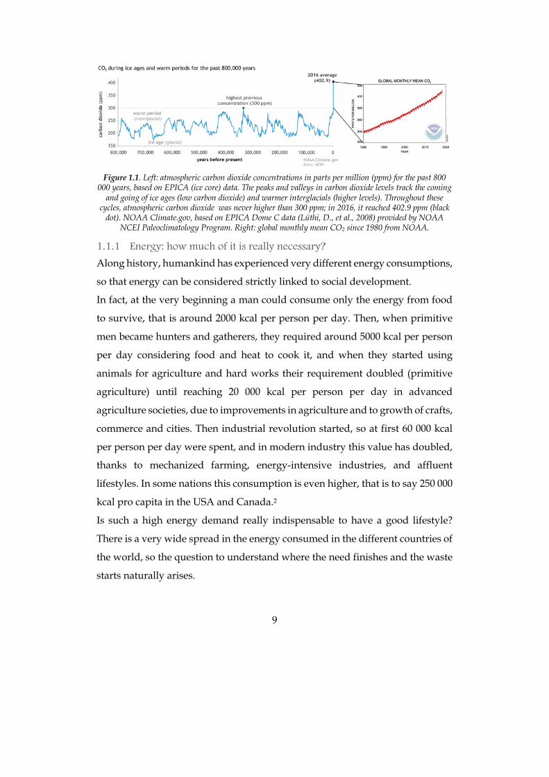
between the use of fossil fuels and global warming is clear if we look at plots
showing the mean temperature and the CO2 concentration in the atmosphere:
they show the very same trend (Figure 1.1). Even if fossil fuels were
inexhaustible sources, it is compulsory to find alternative ways to produce the
energy we need to maintain our lifestyle, otherwise we are going to destroy our
planet, and finding another one to live in would be even more difficult.
9
Figure 1.1. Left: atmospheric carbon dioxide concentrations in parts per million (ppm) for the past 800
000 years, based on EPICA (ice core) data. The peaks and valleys in carbon dioxide levels track the coming and going of ice ages (low carbon dioxide) and warmer interglacials (higher levels). Throughout these
cycles, atmospheric carbon dioxide was never higher than 300 ppm; in 2016, it reached 402.9 ppm (black dot). NOAA Climate.gov, based on EPICA Dome C data (Lüthi, D., et al., 2008) provided by NOAA
NCEI Paleoclimatology Program. Right: global monthly mean CO2 since 1980 from NOAA.
1.1.1 Energy: how much of it is really necessary?
Along history, humankind has experienced very different energy consumptions,
so that energy can be considered strictly linked to social development.
In fact, at the very beginning a man could consume only the energy from food
to survive, that is around 2000 kcal per person per day. Then, when primitive
men became hunters and gatherers, they required around 5000 kcal per person
per day considering food and heat to cook it, and when they started using
animals for agriculture and hard works their requirement doubled (primitive
agriculture) until reaching 20 000 kcal per person per day in advanced
agriculture societies, due to improvements in agriculture and to growth of crafts,
commerce and cities. Then industrial revolution started, so at first 60 000 kcal
per person per day were spent, and in modern industry this value has doubled,
thanks to mechanized farming, energy-intensive industries, and affluent
lifestyles. In some nations this consumption is even higher, that is to say 250 000
kcal pro capita in the USA and Canada.2
Is such a high energy demand really indispensable to have a good lifestyle?
There is a very wide spread in the energy consumed in the different countries of
the world, so the question to understand where the need finishes and the waste
starts naturally arises.
10
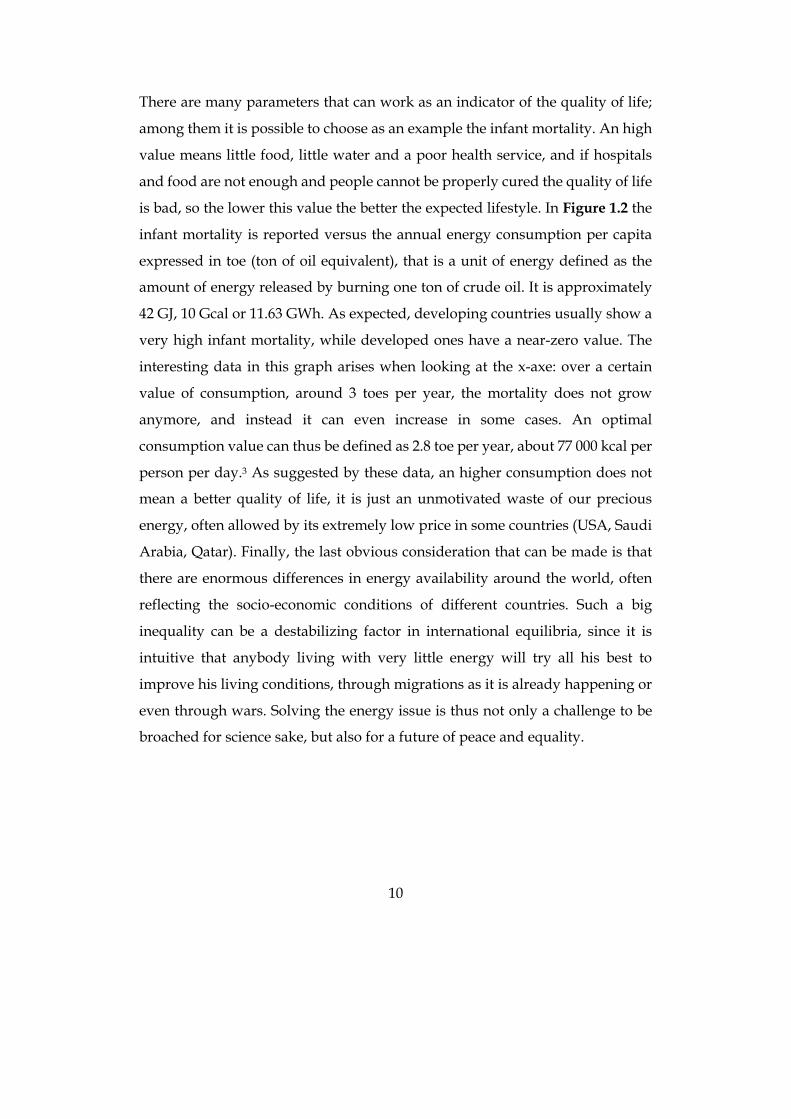
There are many parameters that can work as an indicator of the quality of life;
among them it is possible to choose as an example the infant mortality. An high
value means little food, little water and a poor health service, and if hospitals
and food are not enough and people cannot be properly cured the quality of life
is bad, so the lower this value the better the expected lifestyle. In Figure 1.2 the
infant mortality is reported versus the annual energy consumption per capita
expressed in toe (ton of oil equivalent), that is a unit of energy defined as the
amount of energy released by burning one ton of crude oil. It is approximately
42 GJ, 10 Gcal or 11.63 GWh. As expected, developing countries usually show a
very high infant mortality, while developed ones have a near-zero value. The
interesting data in this graph arises when looking at the x-axe: over a certain
value of consumption, around 3 toes per year, the mortality does not grow
anymore, and instead it can even increase in some cases. An optimal
consumption value can thus be defined as 2.8 toe per year, about 77 000 kcal per
person per day.3 As suggested by these data, an higher consumption does not
mean a better quality of life, it is just an unmotivated waste of our precious
energy, often allowed by its extremely low price in some countries (USA, Saudi
Arabia, Qatar). Finally, the last obvious consideration that can be made is that
there are enormous differences in energy availability around the world, often
reflecting the socio-economic conditions of different countries. Such a big
inequality can be a destabilizing factor in international equilibria, since it is
intuitive that anybody living with very little energy will try all his best to
improve his living conditions, through migrations as it is already happening or
even through wars. Solving the energy issue is thus not only a challenge to be
broached for science sake, but also for a future of peace and equality.
11
Figure 1.2. Infant mortality versus per capita annual energy consumption of selected nations. Reproduced
from Ref. 3 with permission from Wiley.
An example of unmotivated energy waste is linked to food waste, another
consequence of consumerism and loss of care for our planet, that also implies a
waste of cultivated land, irrigation water and pesticides, and a useless evolution
of methane in landfills. In fact, 10% of U.S. energy is used to make food available,
such as for packaging, refrigeration, agriculture, transport and sale,4 and the US
Department of Agriculture estimates that between 30 and 40% of food is thrown
away from the farmer to the consumer: this means that 3-4% of US energy is
wasted too.
1.1.2 Energy producing other energy (EROI)
It is intuitive that energy is needed to produce any device, and this is also true
when speaking about energy producing devices. So, to produce new energy
some energy is needed. There is a parameter indicating how much the process
is efficient, and it is called Energy Return On Investment (EROI).5 EROI is a
unitless ratio, defined as the ratio of the gross energy output over the operating
lifetime for an energy supply system, and the sum of the energy for
manufacture, construction, operation and maintenance, decommissioning and
disposal/recycling during the system’s project life-cycle. A related concept to
12
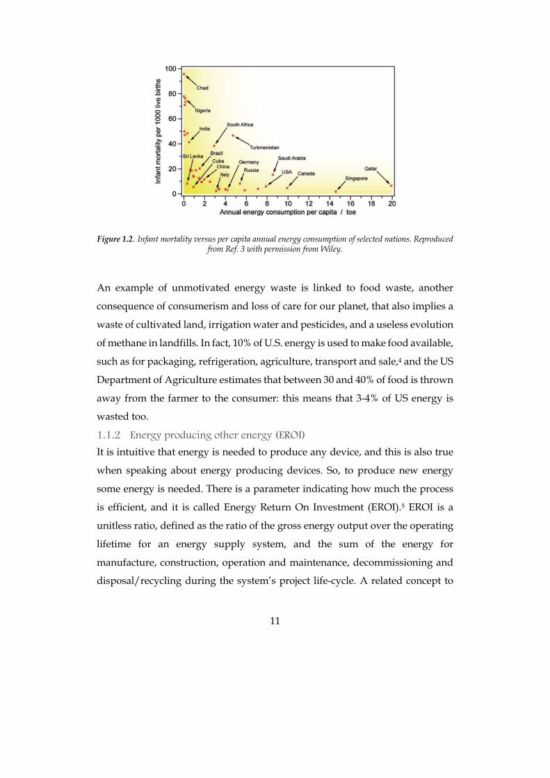
EROI is that of net energy, defined as the difference between the energy acquired
from a given source (gross energy, Eout) and the energy used to obtain and
deliver that energy (Ein), measured over a full life cycle:
𝐸𝑅𝑂𝐼 =𝐸&'(𝐸)*
𝑛𝑒𝑡𝑒𝑛𝑒𝑟𝑔𝑦 = 𝐸&'( − 𝐸)* = 𝐸&'((1 −1
𝐸𝑅𝑂𝐼)
An high EROI value means that just a small amount of energy has to be used to
produce a very big amount of new energy, and this usually means that energy
price is low. Considering 0.38 €/L the present crude oil price, it is cheaper than
many natural water or soft drink bottle, and even considering 1.60 €/L the price
for petrol (taxed over 65%), it is still less expensive than the price of some
expensive famous brand water bottles (for example, Perrier water price is over
3 €/L). It is thus clear that a high demanding lifestyle like the one we are used
to is possible only with high EROI energy sources and the low price we pay for
them.3
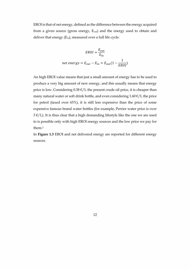
In Figure 1.3 EROI and net delivered energy are reported for different energy
sources.
13
Figure 1.3. Relationship between net delivered energy and decreasing EROI. A qualitative indication of
net energy obtainable from some selected energy sources or technologies is shown. The grey portion represents the energy to be reinvested to convert primary energy into usable energy. Reproduced from Ref.
3 with permission from Wiley.
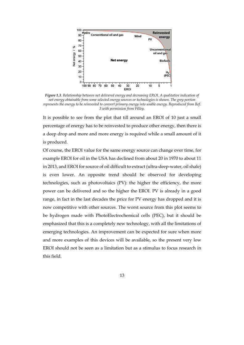
It is possible to see from the plot that till around an EROI of 10 just a small
percentage of energy has to be reinvested to produce other energy, then there is
a deep drop and more and more energy is required while a small amount of it
is produced.
Of course, the EROI value for the same energy source can change over time, for
example EROI for oil in the USA has declined from about 20 in 1970 to about 11
in 2013, and EROI for source of oil difficult to extract (ultra-deep-water, oil shale)
is even lower. An opposite trend should be observed for developing
technologies, such as photovoltaics (PV): the higher the efficiency, the more
power can be delivered and so the higher the EROI. PV is already in a good
range, in fact in the last decades the price for PV energy has dropped and it is
now competitive with other sources. The worst source from this plot seems to
be hydrogen made with PhotoElectrochemical cells (PEC), but it should be
emphasized that this is a completely new technology, with all the limitations of
emerging technologies. An improvement can be expected for sure when more
and more examples of this devices will be available, so the present very low
EROI should not be seen as a limitation but as a stimulus to focus research in
this field.
14
1.1.3 Looking for clean energy
It is clear that energy is essential to live in acceptable conditions, but it is
mandatory to produce it in a clean way to avoid pollution and a further increase
in global temperature. Renewable energy exists since long ago, wind mills and
water mills can be considered one of the first examples, but also electricity has
been produced since the XIX century employing water. The first hydroelectric
plant was put into operation on September 30, 1882 at Appleton, Wisconsin,
with an output of 12.5 kW. It was called the Vulcan Street Plant and it was the
first Edison hydroelectric power plant. Later on, many other plants were built,
and Italy hosts many of them. Besides water, there are other sources for clean
energy, such as sun, geothermical, wind, and many of them would be enough
to cover the global energy need.
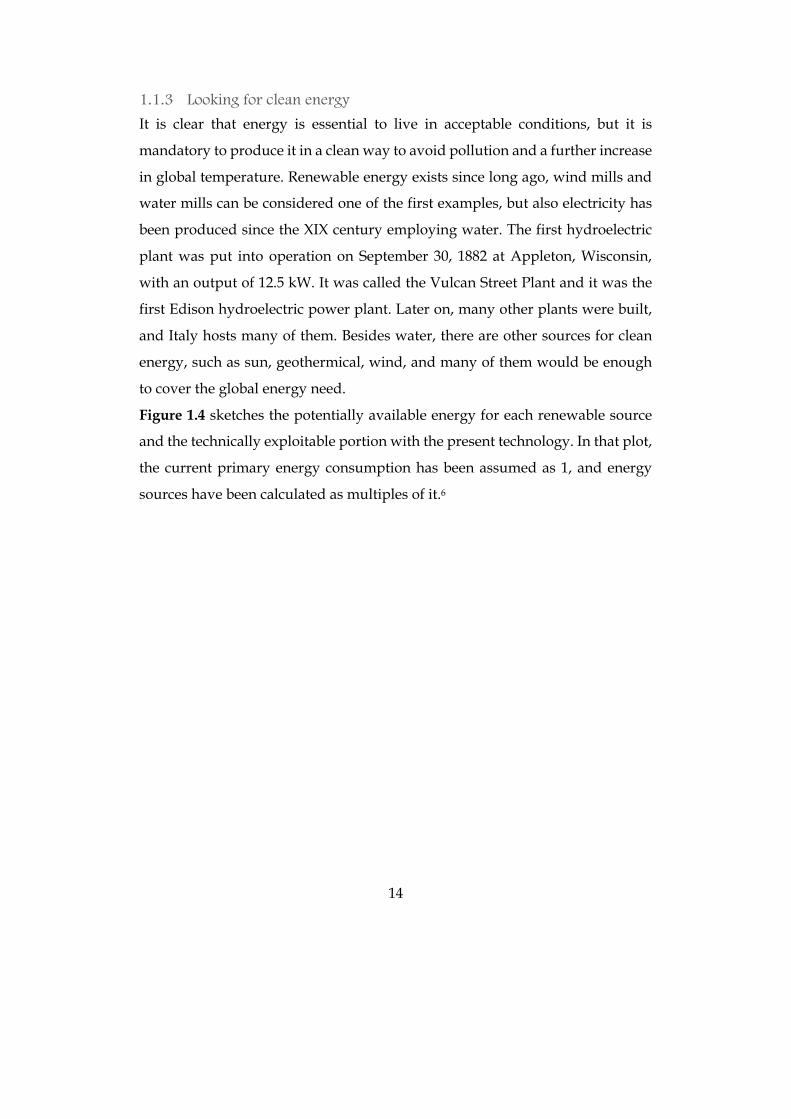
Figure 1.4 sketches the potentially available energy for each renewable source
and the technically exploitable portion with the present technology. In that plot,
the current primary energy consumption has been assumed as 1, and energy
sources have been calculated as multiples of it.6
15
Figure 1.4. Schematic representation of the relative amounts of potentially available (light colour) and technically exploitable (dark colour) renewable energies, compared to the world current primary energy
consumption assumed as 1. Solar energy bars have been reduced to 1/10 for better readability.
The plot clearly shows that it would be possible to rely on renewable sources
alone even today, since either wind and solar energy would be enough to fulfil
our needs; other sources instead could be interesting with an improved
technology to collect them.
The most promising energy source is sun, since the power coming from it is
orders of magnitude higher than our needs, even considering that they are going
to grow in the future due to the developing countries demand (in the last decade,
the global primary energy consumption has grown at an average 2.1% per
year).7 According to British Petroleum, in 2014 the average rate of consumption
has been 17.2 TW, while 90 PW are coming from sun on Earth’s surface every
year, so it would be enough to cover 0.16% of Earth with 10% efficient solar
panels and our needs would be satisfied.8
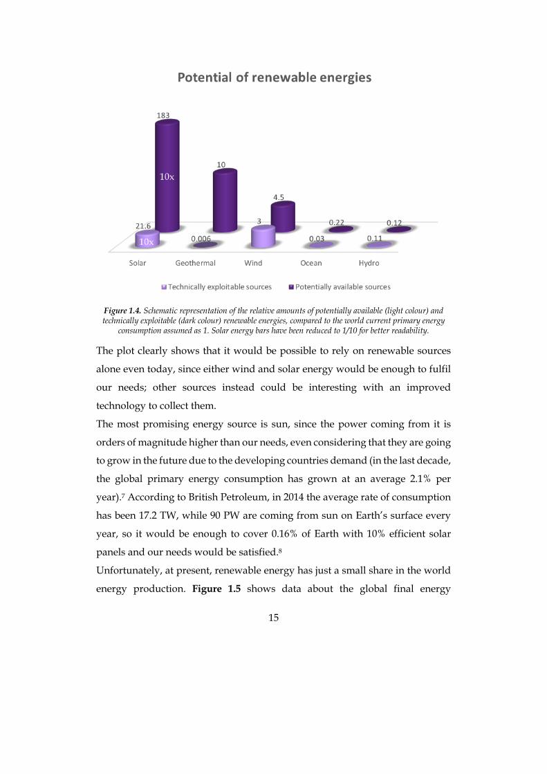
Unfortunately, at present, renewable energy has just a small share in the world
energy production. Figure 1.5 shows data about the global final energy
16
consumption: the biggest part is generated by fossil fuels, renewable energies
account for the 10.4%, and solar power is just a small portion of that percentage.
The good news is that during 2017 the total capacity of photovoltaics (PV)
increased by nearly one-third, going from 302 GW to 404 GW,9 mostly thanks to
new installations in China (50% of the market) and India. Developing countries
investing in this technology is a good hint of their will to satisfy their energy
demand without increasing pollution and CO2 emissions.
Figure 1.5. Estimated renewable share of total final energy consumption, 2016, from REN21 Global
Status Report, 2018.
One of the drawbacks of PV energy is that its production is discontinuous, i.e.
PV panels do not work in the night and in cloudy days, and another one is that
electricity storage is not straightforward. At present, these limitations are
overcome by using batteries to directly store electricity and electrolysers to
transform electricity in solar fuels such as Hydrogen. Both these solutions mean
a further transformation of solar electricity in another device, and this means an
efficiency loss for the whole process from sun to energy storage. A more efficient
way to obtain the same result would thus be a single device that transforms solar
light in solar fuels, exactly as it happens in natural photosynthesis, where leaves
transform light and water in carbohydrates for plants feeding. This process is

17
called artificial photosynthesis and, even if at present time its efficiency is very
low, it is a very promising technology for the future.
In this work both the traditional solar cell approach and the innovative artificial
photosynthesis one have been afforded, in order to have a wider view of eco-
friendly and green solutions for the energetic issue.
18
1.2 Photovoltaic energy One fifth of the Total Final Energy Consumption in 2015 was constituted by
electricity, and very interestingly 25% of it was produced from renewable
sources. The biggest part came from hydroelectric plants (16.4%), then from
wind, from Bio-power and 1.9% came from solar photovoltaic (PV).
PV is a very promising technology that could potentially fulfil high energy
needs thanks to the very high amount of solar energy hitting Earth everyday, as
it was stated in the previous section. 90 PW of solar light arrive every year on
almost every part of the Earth, so that electricity could be produced anywhere
without the limit of geographic concentration of fields, as it happens with oil,
with solar plants where needed. This widespread distribution of an energy
source would avoid wars and almost monopolistic price variations, if cheap and
abundant-materials-based solar panels were employed.
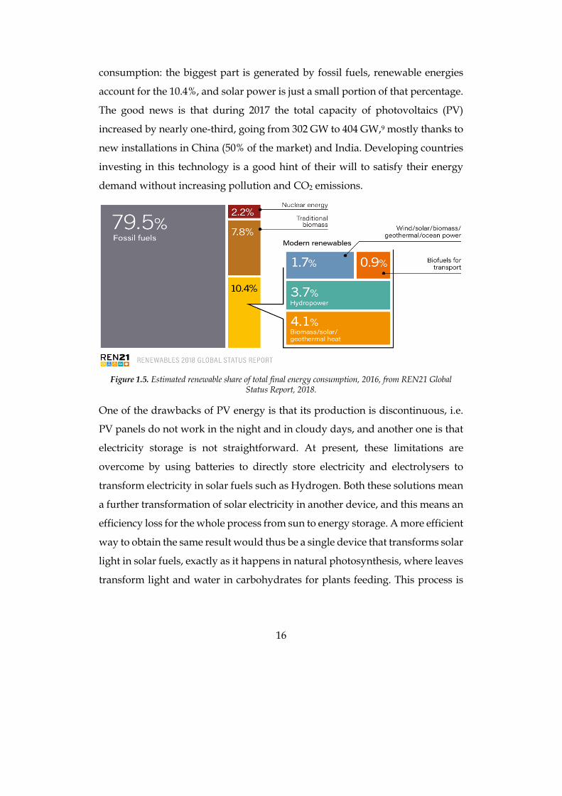
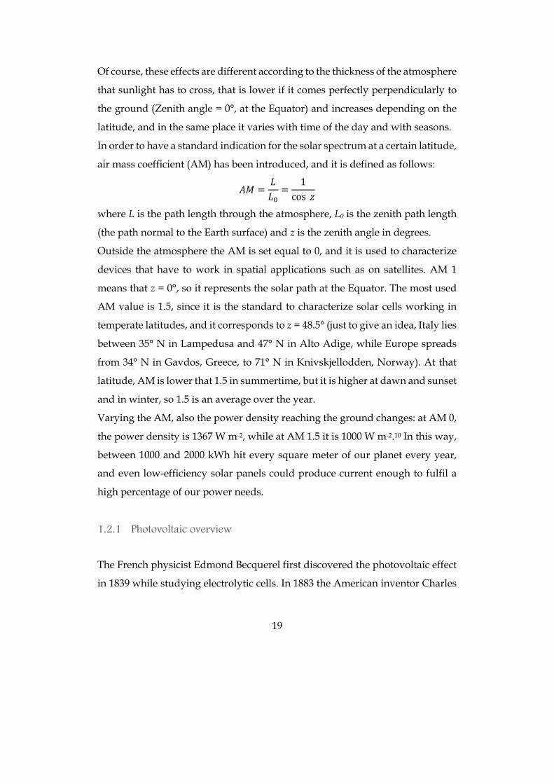
Sun has an emission spectrum that can be approximated with a 5800 K black-
body, but its spectrum recorded on Earth surface is different: some wavelengths
in fact are absorbed by our atmosphere, mainly by O2, H2O, N2, CO2 and O3, that
cuts off the biggest part of the UV portion; furthermore, particulate present in
the atmosphere scatters light, particularly the higher frequency blue light
(Figure 1.6).
Figure 1.6. Solar spectrum at the sea level compared with the one outside atmosphere and the black-body emission one. From Krondratjev, K Y., Radiation in the Atmosphere, Academic Press, New York, 1969.
19
Of course, these effects are different according to the thickness of the atmosphere
that sunlight has to cross, that is lower if it comes perfectly perpendicularly to
the ground (Zenith angle = 0°, at the Equator) and increases depending on the
latitude, and in the same place it varies with time of the day and with seasons.
In order to have a standard indication for the solar spectrum at a certain latitude,
air mass coefficient (AM) has been introduced, and it is defined as follows:
𝐴𝑀 =𝐿𝐿9=
1cos 𝑧
where L is the path length through the atmosphere, L0 is the zenith path length
(the path normal to the Earth surface) and z is the zenith angle in degrees.
Outside the atmosphere the AM is set equal to 0, and it is used to characterize
devices that have to work in spatial applications such as on satellites. AM 1
means that z = 0°, so it represents the solar path at the Equator. The most used
AM value is 1.5, since it is the standard to characterize solar cells working in
temperate latitudes, and it corresponds to z = 48.5° (just to give an idea, Italy lies
between 35° N in Lampedusa and 47° N in Alto Adige, while Europe spreads
from 34° N in Gavdos, Greece, to 71° N in Knivskjellodden, Norway). At that
latitude, AM is lower that 1.5 in summertime, but it is higher at dawn and sunset
and in winter, so 1.5 is an average over the year.
Varying the AM, also the power density reaching the ground changes: at AM 0,
the power density is 1367 W m-2, while at AM 1.5 it is 1000 W m-2.10 In this way,
between 1000 and 2000 kWh hit every square meter of our planet every year,
and even low-efficiency solar panels could produce current enough to fulfil a
high percentage of our power needs.
1.2.1 Photovoltaic overview
The French physicist Edmond Becquerel first discovered the photovoltaic effect
in 1839 while studying electrolytic cells. In 1883 the American inventor Charles
20
Fritts built the first solar cell, consisting of a junction of selenium and gold, with
a 1% efficiency. To have a significant growth in efficiency and thus commercially
applicable solar cells it was necessary to wait until the ’50s: in 1954 at Bell Labs
the first silicon solar cell with a 6% efficiency was announced,11 and from then
efficiency kept on growing and many other materials have been investigated.
Technologic improvements allowed a dramatic decrease of solar panel cost: the
price of silicon solar modules in 1977 was 76 $ per watt, while in 2018 it is only
0.27 $ per watt.12
It is possible to divide solar cells into three generations, according to different
degrees of technological advancement and their availability in terms of costs and
materials. The first and the second generations employ inorganic semiconductor
materials; the first generation is constituted by both monocrystalline and
polycrystalline silicon based solar cells that were firstly studied and
commercialized and they are the most widespread installed even nowadays
since they are very efficient (around 15% efficiency) and very stable (usually
they have a 25-years-long life). Thin-film devices instead belong to the second
generation, they require smaller quantities of active material than standard
silicon cells to reduce costs and use both amorphous silicon and different
semiconductors, such as CdTe and CIGS (Copper Indium Gallium Selenide), the
efficiency is a little lower (10-15%) but, since the active layer is very thin, they
can be a little bit flexible; unfortunately, the production includes expensive steps
(such as high vacuum deposition) and they contain scarce and toxic elements,
so that they have a limited market. The most recent types of solar cells are
included in the third generation, that comprises several devices, both organic
and inorganic. The inorganic ones are mainly expensive high performance
experimental multi-junction solar cells which hold the world record in solar cell
performance, that can be applied only in solar concentrators or in spatial
applications due to the high cost. The other solar cells belonging to the third
generation instead aim to give a low cost and often portable solution to produce
21
energy everywhere and comprise organic solar cells (OPV), dye-sensitized solar
cells (DSSC), perovskite solar cells (PSC), quantum dot solar cells and also
multijunction of these novel categories with silicon solar cells, for example. At
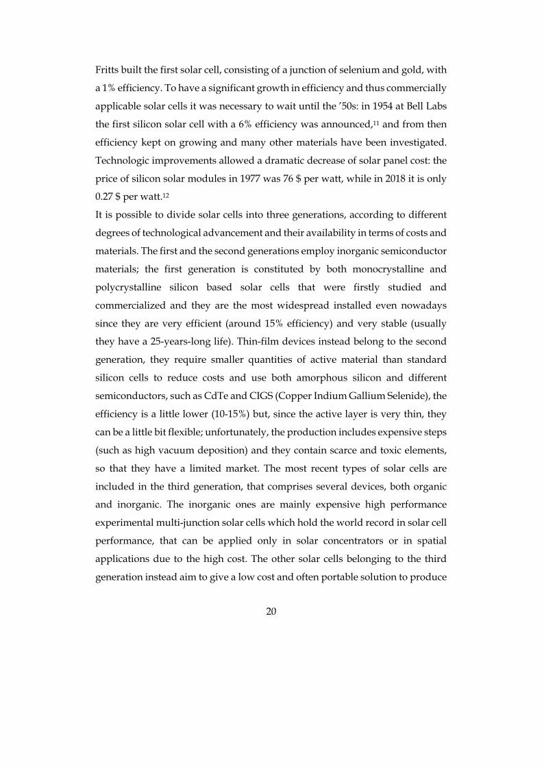
the research level there are institutions that certify the advancement in efficiency
reached for each existing technology of solar cells; a commonly used example is
the NREL chart published by the US National Renewable Energy Laboratory
(Figure 1.7).13
Figure 1.7. Efficiencies of certified best cells in research conditions from National Renewable Energy
Laboratory (NREL) updated to 2018.
This work will focus on DSSCs since the research group had already gained the
know-how both for the synthesis of dyes and for the device assembly. It is worth
noting that, even if DSSC efficiency is lower than c-Si one, they have a big
advantage, that is the possibility to work even in low-light environment. In fact,
while silicon solar cells efficiency is very low when light intensity is low, DSSCs
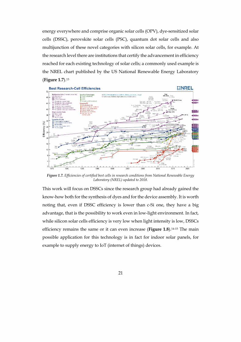
efficiency remains the same or it can even increase (Figure 1.8).14-15 The main
possible application for this technology is in fact for indoor solar panels, for
example to supply energy to IoT (internet of things) devices.
22
Figure 1.8. Graph of the efficiency of DSSC modules optimized for indoor applications in comparison with
crystalline and amorphous silicon. From Fujikura catalogue (www.fujikura.co.uk/products/energy-and-environment/dye-sensitized-solar-cell).
The history of DSSCs dates back to the early ‘80s when the first dyes-sensitizers
in the form of organometallic ruthenium complexes with bi-pyridines bi-
carboxylated were used to activate the titanium oxide16 and their development
continued in the second half of the ‘80s using ruthenium complexes with three
bi-pyridines bi-carbossilate.17 A milestone was the famous publication on
Nature magazine in 1991 from Brian O’Regan and Michael Grätzel, where they
presented for the first time a photovoltaic device based on titanium dioxide
functionalized with a trimeric ruthenium complex using bi-pyridines bi-
carboxylated as ligands.18 Since then, various complexes of ruthenium have been
tested and, in 1993, Grätzel reported as sensitizers a series of mononuclear
ruthenium complexes, the best performing of which was N3, where ruthenium
shows two thiocyanate ligands and two bi-pyridines substituted in position 4,
4’ with carboxylic acid units.19 Carboxyl groups are very important because they
allow the anchoring of the dye to titanium dioxide and for their conjugation to
the pyridine groups. In the ground state electron density is concentrated onto
the metal center, but in the excited state, resulting from the absorption of
electromagnetic radiation, such density is concentrated on carboxylate groups
linked to TiO2. The thiocyanate groups are electron-donors which increase the
absorption coefficient of the complex. Nazeeruddin and coworkers have tested
different forms of protonated N3: N712 has four carboxylate groups with tetra-
23
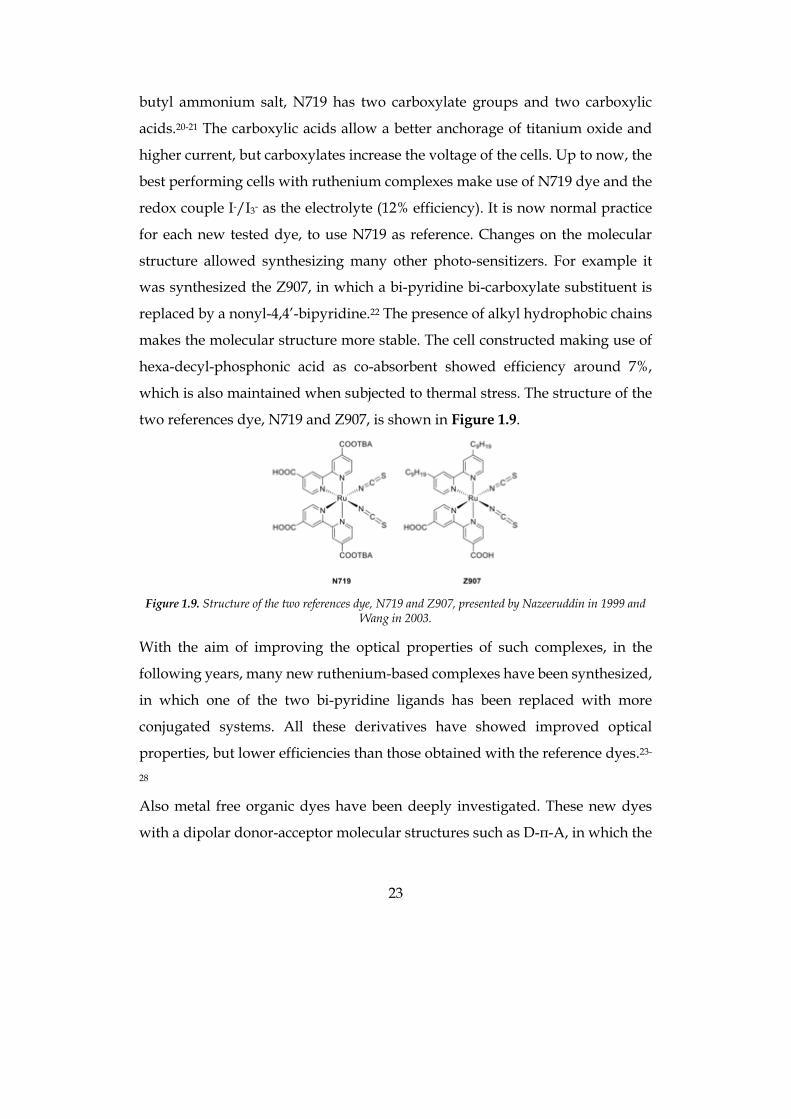
butyl ammonium salt, N719 has two carboxylate groups and two carboxylic
acids.20-21 The carboxylic acids allow a better anchorage of titanium oxide and
higher current, but carboxylates increase the voltage of the cells. Up to now, the
best performing cells with ruthenium complexes make use of N719 dye and the
redox couple I-/I3- as the electrolyte (12% efficiency). It is now normal practice
for each new tested dye, to use N719 as reference. Changes on the molecular
structure allowed synthesizing many other photo-sensitizers. For example it
was synthesized the Z907, in which a bi-pyridine bi-carboxylate substituent is
replaced by a nonyl-4,4’-bipyridine.22 The presence of alkyl hydrophobic chains
makes the molecular structure more stable. The cell constructed making use of
hexa-decyl-phosphonic acid as co-absorbent showed efficiency around 7%,
which is also maintained when subjected to thermal stress. The structure of the
two references dye, N719 and Z907, is shown in Figure 1.9.
Figure 1.9. Structure of the two references dye, N719 and Z907, presented by Nazeeruddin in 1999 and
Wang in 2003.
With the aim of improving the optical properties of such complexes, in the
following years, many new ruthenium-based complexes have been synthesized,
in which one of the two bi-pyridine ligands has been replaced with more
conjugated systems. All these derivatives have showed improved optical
properties, but lower efficiencies than those obtained with the reference dyes.23-
28
Also metal free organic dyes have been deeply investigated. These new dyes
with a dipolar donor-acceptor molecular structures such as D-π-A, in which the
24
acceptor is also linked to the anchoring group that is generally a unit vinyl-
cyano-acetic. As donor groups, different electro-rich donor moieties have been
investigated and different π-spacers have been bonded on each. As for the latter,
generally the most efficient are the thiophenic or poly-thiophenic ones. Among
the different investigated donors groups, the most performing were found to be
coumarin, indolines, tetrahydroquinoline, carbazoles, dialkylaniline, and
especially triphenylamine. Further structural modifications, followed by an
optimization of the devices have allowed obtaining results comparable with
those of the organometallic reference dyes.29-34 The literature on these
compounds is very extensive (Figure 1.10), since it is simple from the synthetic
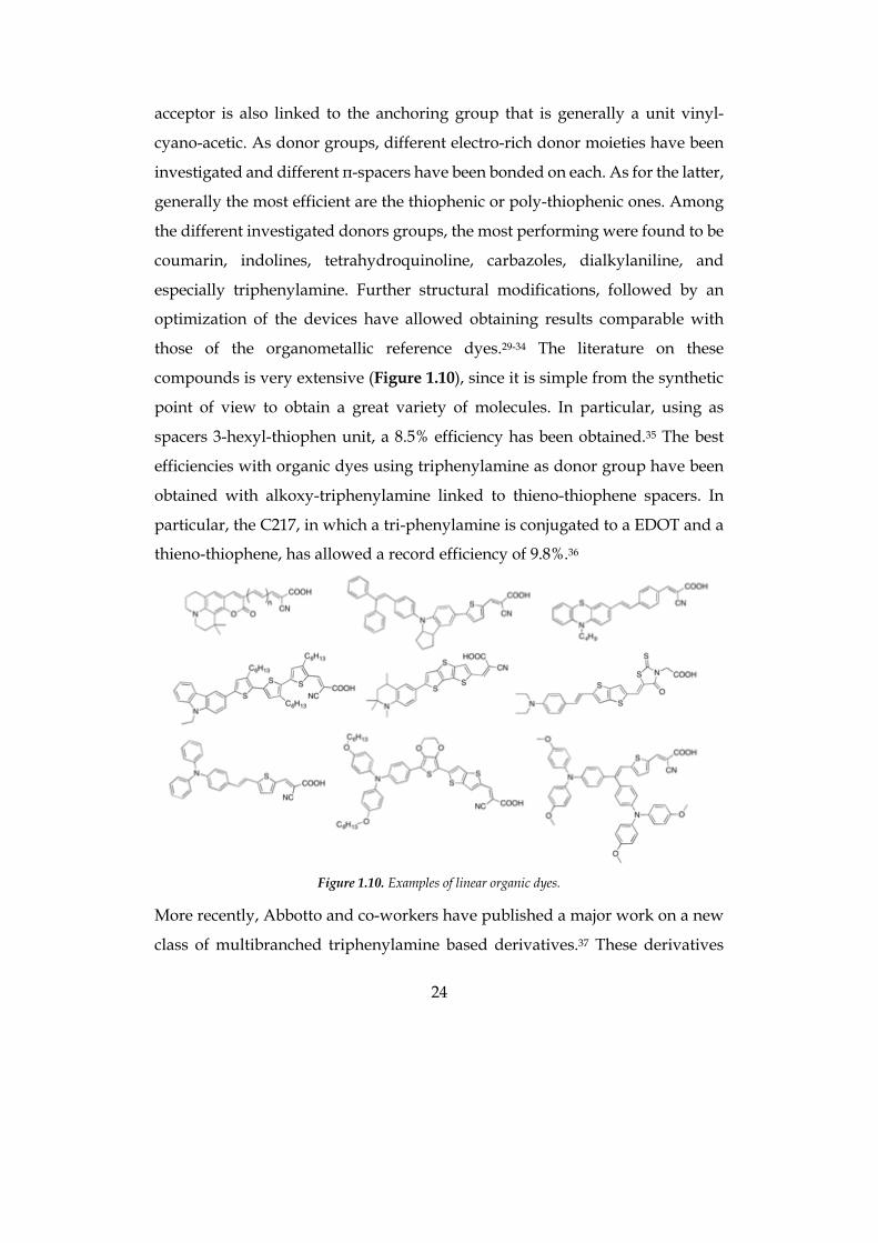
point of view to obtain a great variety of molecules. In particular, using as
spacers 3-hexyl-thiophen unit, a 8.5% efficiency has been obtained.35 The best
efficiencies with organic dyes using triphenylamine as donor group have been
obtained with alkoxy-triphenylamine linked to thieno-thiophene spacers. In
particular, the C217, in which a tri-phenylamine is conjugated to a EDOT and a
thieno-thiophene, has allowed a record efficiency of 9.8%.36
Figure 1.10. Examples of linear organic dyes.
More recently, Abbotto and co-workers have published a major work on a new
class of multibranched triphenylamine based derivatives.37 These derivatives
25
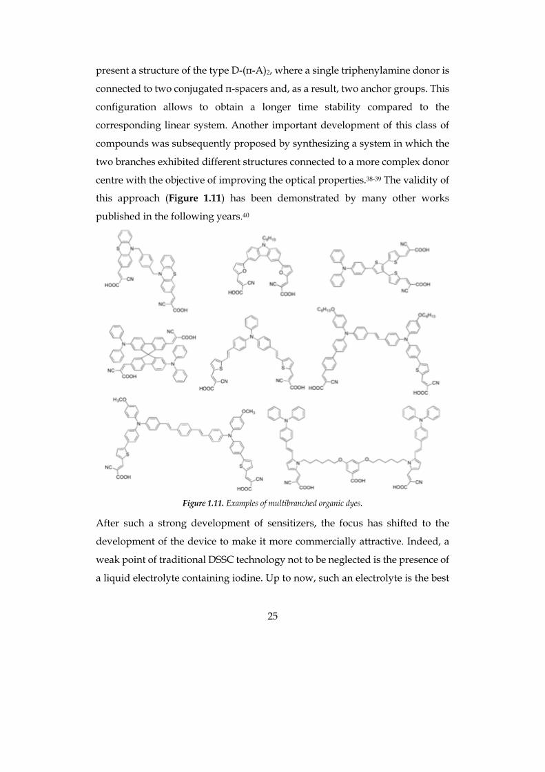
present a structure of the type D-(π-A)2, where a single triphenylamine donor is
connected to two conjugated π-spacers and, as a result, two anchor groups. This
configuration allows to obtain a longer time stability compared to the
corresponding linear system. Another important development of this class of
compounds was subsequently proposed by synthesizing a system in which the
two branches exhibited different structures connected to a more complex donor
centre with the objective of improving the optical properties.38-39 The validity of
this approach (Figure 1.11) has been demonstrated by many other works
published in the following years.40
Figure 1.11. Examples of multibranched organic dyes.
After such a strong development of sensitizers, the focus has shifted to the
development of the device to make it more commercially attractive. Indeed, a
weak point of traditional DSSC technology not to be neglected is the presence of
a liquid electrolyte containing iodine. Up to now, such an electrolyte is the best
26
redox mediator in order to obtain high efficiencies. There have been some
attempts to replace iodine with more efficient redox systems such as the redox
couple Co2+/Co3+ with which, using a zinc porphyrin YD2-o-C8, Yella and
coworkers have reached and exceeded the previous record efficiency bringing
the value 12.7%.41 Hanaya and coworkers hold the current record efficiency
reported in literature of 14.7% using a cosensitized photoanode with an
alkoxysilyl-anchor dye ADEKA-1 and a carboxy-anchor organic dye LEG4 in
presence of a cobalt based electrolyte.42 This outstanding result, however, was
not enough to push the commercialisation of this type of devices because, once
again, made with sensitizers with a complex synthesis and in the presence of a
liquid electrolyte particularly toxic due to the presence of cobalt salts. In order
to make these devices attractive to the market, it was necessary to develop solid
state systems, thus eliminating the risk related to the presence of electrolytes
containing solvents and toxic or corrosive components,43-44 or to develop new
eco-friendly electrolytes, for example using water as a solvent. At the beginning
of studies on DSSCs, water was seen as a poisoner to be completely avoided
because it was considered to be responsible of the performance decay of cells
along time, even if in the ‘80s it was a commonly used solvent in DSSC ancestors
(also the aforementioned work from Grätzel of 1988 used a water based
electrolyte). A study from Lindquist in 1998 verified the effect of water
contamination in a iodine-based organic electrolyte solution and proposed some
hypothesis: water could coordinate with the TiO2 surface Ti atoms, thus limiting
the I3- recombination with TiO2 conduction band and increasing the open circuit
voltage (Voc), but at the same time water significantly reduced the short circuit
current (Jsc) due to a possible desorption of the dye from the semiconductor
surface following the hydrolysis of carboxylate anchoring moieties, resulting in
the carboxylic acid form of the free dye.45 After a paper by O’ Reagan published
in 2010 in which water was added in different proportions to an organic
electrolyte with little decay in the performance the trend has been reversed, and
27
many researchers are now working on aqueous DSSC. Many works followed a
similar path of mixing water and organic solvents, often adding surfactants for
a better compatibility, but there are also many examples of electrolytes that
adopt only water as solvent.45-47 The efficiencies unfortunately are usually very
low, ranging from less than 1% to a record of 6%.48
A problem to address when considering aqueous electrolyte solutions is the
hydrophilicity of the dye, that is responsible of the very important aspect of
photoanode/electrolyte interface. Three main approaches have been proposed
in literature to avoid dye desorption in water due to carboxylic bond hydrolysis:
one is to use traditional ruthenium complexes in strongly acidic pH conditions,
but these cells are not stable for a long time,49 or to protect the dye with an
inorganic coating using atomic layer deposition (ALD), improving the stability,
but this is a very expensive technique.50 Another possibility is to employ
hydrophobic organic dyes, but the hydrophobicity hinders the electrolyte
penetration in the cavities of the mesostructured photoelectrode, limiting the
photocurrent of the cell. The third possible approach is to use hydrophilic dyes
specifically designed to work in an aqueous environment that offer a good
wettability of the electrode;51 it is also possible to protect the TiO2 anchoring
group using an hydrophobic one, but the stability is short.52 C. Barolo and
coworkers carried out an exhaustive work testing nine sensitizers of very
different nature, changing the anchoring unit, the polarity of the molecular
backbone, the absorption region within the visible spectrum, and the presence
of metal centers, to correlate the molecular structure to stability in water.
Indolenine sensitizers gave the best results, even if the photovoltaic efficiencies
were very low (0.12 to 0.20%).53
Once the dye has been chosen, it is necessary to optimize the electrolyte
components: usually, if a completely aqueous cell is considered, inorganic salts
are a common choice, because of their good solubility in water and also because
they are not toxic like ionic liquids and they are cheaper. The common choice is
28
thus among iodine salts (NaI, KI, LiI), in variable concentrations and
proportions to I2, adding in some cases other components such as guanidinium
thiocyanate (GuSCN) and chenodeoxycholic acid (CDCA).47, 51 The efficiencies
reported are usually lower than 2%. Ionic liquids have been compatibilized with
water in various dilutions by adding surfactants like Triton X-100, resulting in
similar efficiency.46 Finally, good results have been obtained using cobalt based
electrolyte solutions, with efficiency over 5%, but cobalt salts are very toxic, so
they are in contrast with the eco-friendly aim of aqueous DSSC.54-55
Some improvements can be obtained when changing the counter electrode,
switching from classical platinum to PEDOT over the conductive glass. Both
these materials show total wetting upon deposition of water on the surface,
therefore the increased photocurrent recorded cannot be ascribed to a better
wettability. This improvement has thus been attributed to the high surface area
of PEDOT due to a leaf-like structure that increases the catalytic activity. Also a
reduced dye desorption has been reported when using PEDOT counter
electrodes, ascribed to the ability of PEDOT to include ions in its matrix, that in
this way cannot absorb on TiO2. Efficiency reached 4.04% at 0.5 sun.51 Finally,
PEDOT counter electrodes are cheaper and more eco-friendly than platinum, as
they are fabricated from cheap materials and can be electropolymerized at room
temperature, in deionized water.56
A new frontier for a longer stability of aqueous solar cells is to make more solid
the electrolyte. For example, a recent work employed eco-friendly
carboxymethylcellulose hydrogels containing both NaI and I2 with promising
electrochemical characteristics on charge diffusion and ionic mobility. Even if
they had not outstanding PV properties (the efficiency was 0.72%), they lost only
7% of the efficiency after 29 days of ageing in dark.57
1.2.2 Working principles of DSSC
29
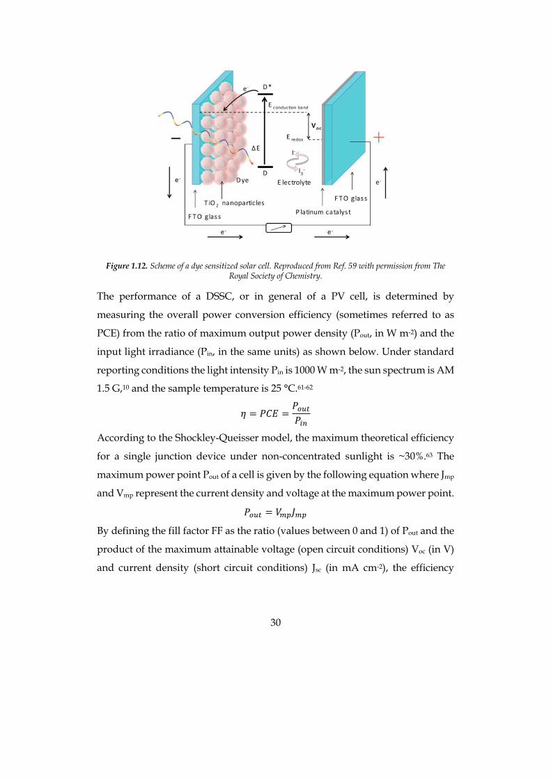
A DSSC is a multi-component device comprising: a) a dye-sensitizer S; b) a n-
type semiconductor metal oxide (typically TiO2); c) a p-type semiconductor or a
redox electrolyte (typically a redox couple); d) a transparent working anode and
a counter electrode (based on fluorine-doped tin oxide, FTO). Under light
irradiation the sensitizer S is excited to state S* from which an electron is injected
into the conduction band (CB) of TiO2, leaving the dye in its oxidized state S+.
The electrons collected at the photoanode are then transferred through the
external circuit to the counter electrode where, via Pt catalysis, they reduce the
electrolyte that then regenerates the sensitizer (S+ → S). If a p-type
semiconductor is used in place of the electrolyte (solid state devices), dye-
regeneration occurs via hole transfer from S+ to the HOMO of the hole
transporter (Figure 1.12).58-59 A DSSC is a very efficient device where, formally,
one photon is converted into one electron without permanent modification of
any component. In addition to the main processes, a number of undesired
pathways and losses are present including recombination of injected electrons
from TiO2 to either S+ or the oxidized form of the electrolyte, incomplete light
harvesting, and inefficient electron transfer from S*. The main source of loss-in
potential of a DSSC is the high overpotential needed to regenerate the dye,
which strongly limits the maximum attainable photovoltage.60
30
Figure 1.12. Scheme of a dye sensitized solar cell. Reproduced from Ref. 59 with permission from The
Royal Society of Chemistry.
The performance of a DSSC, or in general of a PV cell, is determined by
measuring the overall power conversion efficiency (sometimes referred to as
PCE) from the ratio of maximum output power density (Pout, in W m-2) and the
input light irradiance (Pin, in the same units) as shown below. Under standard
reporting conditions the light intensity Pin is 1000 W m-2, the sun spectrum is AM
1.5 G,10 and the sample temperature is 25 °C.61-62
𝜂 = 𝑃𝐶𝐸 =𝑃&'(𝑃)*
According to the Shockley-Queisser model, the maximum theoretical efficiency
for a single junction device under non-concentrated sunlight is ~30%.63 The
maximum power point Pout of a cell is given by the following equation where Jmp
and Vmp represent the current density and voltage at the maximum power point.
𝑃&'( = 𝑉BC𝐽BC
By defining the fill factor FF as the ratio (values between 0 and 1) of Pout and the
product of the maximum attainable voltage (open circuit conditions) Voc (in V)
and current density (short circuit conditions) Jsc (in mA cm-2), the efficiency
31
relationship can be rewritten as follows, which is used to determine the cell
performance.
𝐹𝐹 =𝑃&'(𝑉&F𝐽GF
𝜂 =𝑉&F𝐽GF𝐹𝐹𝑃)*
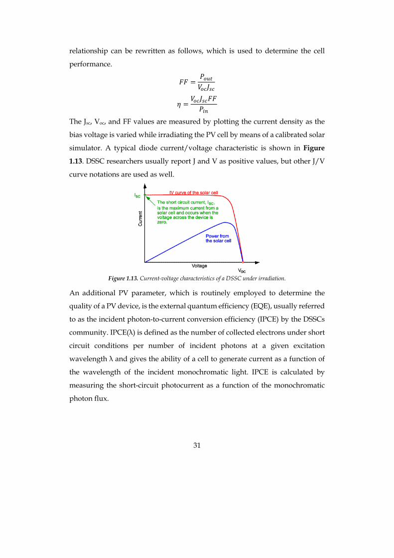
The Jsc, Voc, and FF values are measured by plotting the current density as the
bias voltage is varied while irradiating the PV cell by means of a calibrated solar
simulator. A typical diode current/voltage characteristic is shown in Figure
1.13. DSSC researchers usually report J and V as positive values, but other J/V
curve notations are used as well.
Figure 1.13. Current-voltage characteristics of a DSSC under irradiation.
An additional PV parameter, which is routinely employed to determine the
quality of a PV device, is the external quantum efficiency (EQE), usually referred
to as the incident photon-to-current conversion efficiency (IPCE) by the DSSCs
community. IPCE(λ) is defined as the number of collected electrons under short
circuit conditions per number of incident photons at a given excitation
wavelength λ and gives the ability of a cell to generate current as a function of
the wavelength of the incident monochromatic light. IPCE is calculated by
measuring the short-circuit photocurrent as a function of the monochromatic
photon flux.
32
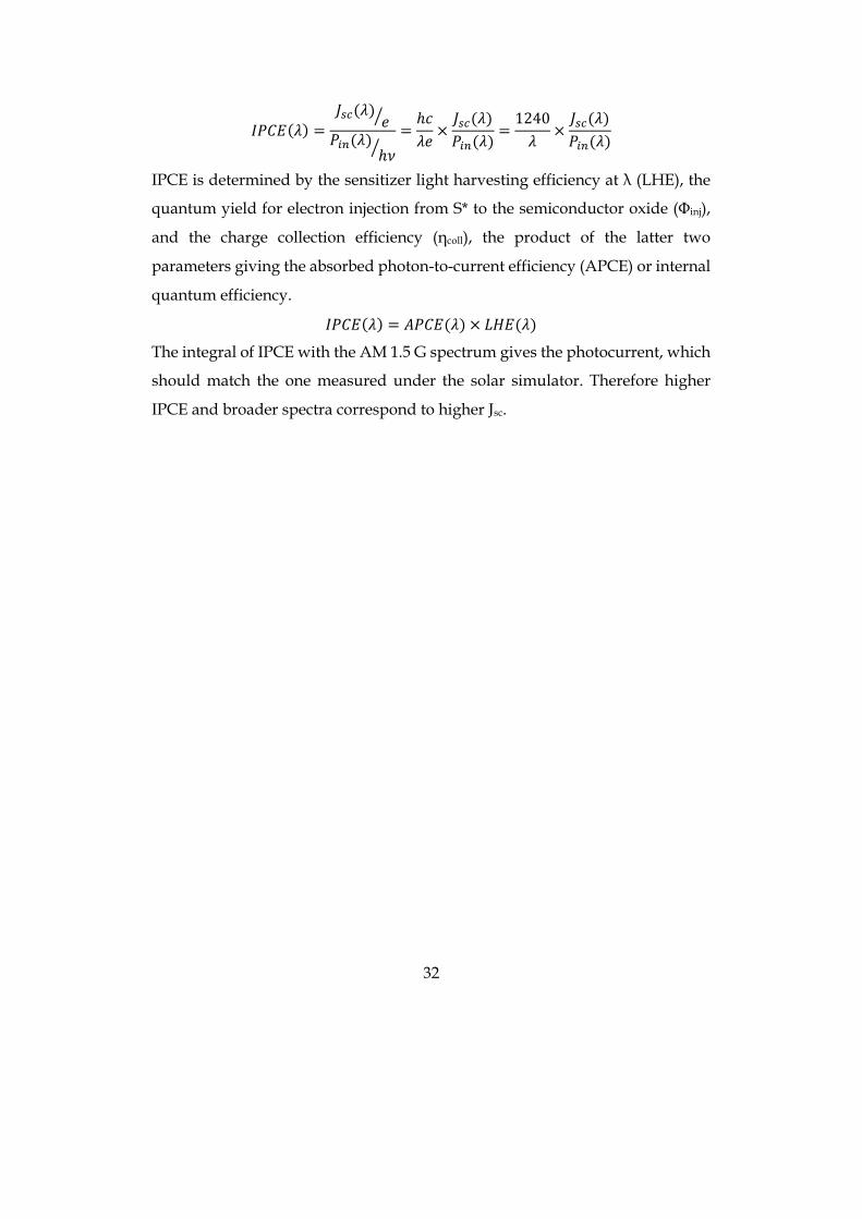
𝐼𝑃𝐶𝐸(𝜆) =𝐽GF(𝜆) 𝑒I𝑃)*(𝜆)
ℎ𝜈I=ℎ𝑐𝜆𝑒×𝐽GF(𝜆)𝑃)*(𝜆)
=1240𝜆
×𝐽GF(𝜆)𝑃)*(𝜆)
IPCE is determined by the sensitizer light harvesting efficiency at λ (LHE), the
quantum yield for electron injection from S* to the semiconductor oxide (Φinj),
and the charge collection efficiency (ηcoll), the product of the latter two
parameters giving the absorbed photon-to-current efficiency (APCE) or internal
quantum efficiency.
𝐼𝑃𝐶𝐸(𝜆) = 𝐴𝑃𝐶𝐸(𝜆) × 𝐿𝐻𝐸(𝜆)
The integral of IPCE with the AM 1.5 G spectrum gives the photocurrent, which
should match the one measured under the solar simulator. Therefore higher
IPCE and broader spectra correspond to higher Jsc.
33
1.3 Artificial photosynthesis and Photoelectrochemical Cell
As already mentioned in the previous sections, the need to leave oil and to look
for a clean energy source is demanding and cannot be further delayed.
Photovoltaics can be a good approach to produce electric current, but it
represents only 20% of the world final energy consumption, while
transportation uses 32% of it. Unfortunately, if for electricity we already have a
25% renewable share, for transport it is only 3%, with a 2.8% of biofuels and
0.3% of renewable electricity. The problem is that it is not easy to store electrons,
so electric cars need big and heavy (and expensive) batteries instead of a 40-60
L fuel tank, and they however have a limited autonomy; the ideal solution
would be to efficiently employ solar light to produce a fuel that can be easily
distributed and stored, with a fast car refilling. A good chance is represented by
hydrogen, that, in principle, could be obtained from the most harmless of
reagents: water.
Current transport situation
In Italy, in 2015 petrol was responsible of 91.9% of transport energy
consumption; methane covered 2.8% of the consumption, biofuels 3.0% and
electricity 2.4% (from elaborazione Gestore Servizi Energetici su dati Eurostat).
As of 1st January 2017, 7.8% of Italian car fleet made use of alternative fuels, with
a bigger part (5.2%) using LPG, a 2.3% using methane and only 0.3% was
represented by hybrid or full electric vehicles (source ACI).
Biofuels are at the moment the principal renewable alternative to fossil fuels for
transportation. Biofuels can come from appositely cultivated biomasses (first
generation system), that thus compete for land with food cultivation, or they can
be obtained from agriculture wastes, such as shells, husks, wood chips or fruit
peels (second generation). The latter approach partly solves the competition for
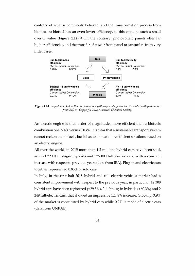
farmland, but the “Sun to wheels” conversion efficiency is extremely low, just
0.03%.3 Chlorophyll photosynthesis has a very low efficiency, around 1%, on the
34
contrary of what is commonly believed, and the transformation process from
biomass to biofuel has an even lower efficiency, so this explains such a small
overall value (Figure 1.14).64 On the contrary, photovoltaic panels offer far
higher efficiencies, and the transfer of power from panel to car suffers from very
little losses.
Figure 1.14. Biofuel and photovoltaic sun-to-wheels pathways and efficiencies. Reprinted with permission
from Ref. 64. Copyright 2015 American Chemical Society.
An electric engine is thus order of magnitudes more efficient than a biofuels
combustion one, 5.4% versus 0.03%. It is clear that a sustainable transport system
cannot reckon on biofuels, but it has to look at more efficient solutions based on
an electric engine.
All over the world, in 2015 more than 1.2 millions hybrid cars have been sold,
around 220 000 plug-in hybrids and 325 000 full electric cars, with a constant
increase with respect to previous years (data from IEA). Plug-in and electric cars
together represented 0.85% of sold cars.
In Italy, in the first half-2018 hybrid and full electric vehicles market had a
consistent improvement with respect to the previous year; in particular, 42 308
hybrid cars have been registered (+29.5%), 2 119 plug-in hybrids (+60.3%) and 2
249 full-electric cars, that showed an impressive 123.8% increase. Globally, 3.9%
of the market is constituted by hybrid cars while 0.2% is made of electric cars
(data from UNRAE).
35
The best seller full-electric car has been the Smart ForTwo (627 units, price from
23 920 €), followed by Nissan Leaf (457 units, price from 29 885 €), Renault Zoe
(426 units, price from 23 300 €) and Tesla Model S (156 units, price from 72 640
€) and Model X (103 units, price from 94 480 €; price data from: Quattroruote).
These selling data show that nowadays electric cars of every category are
available with affordable prices, spanning from city cars, to saloon cars and to
top line cars as Tesla; furthermore, the steep sell increase suggests that Italian
population is willing to move to a clean transport system, even bearing the
actual limitations of full-electric cars.
Their main drawbacks are due to the battery. First of all, it represents half of the
price of the vehicle, and it is subject to ageing in a few years, so that a
substitution has to be taken into account.65 Furthermore, lithium price had a
steep increase in the last years: in the six months ending in May 2016, the price
of pure lithium being exported to China increased of 42%. Limited reserves, that
are mainly localized in single areas, represent an important issue, and they
involve the risk of monopolism like what has happened with oil. For instance,
approximately 70% of global lithium brine (a mineral mixture, usually found in
salt-lake basins, that is the main source for lithium production) resources are
located in just four countries, Argentina, Bolivia, Chile and China, even if other
lithium sources can be exploited.66 Li-ion batteries have an high power density
and are lighter than other batteries, but they however increase the weight of the
car, require space and reduce the performance.67 Finally, batteries offer a limited
autonomy to cars (usually about 200-300 km, even if Tesla Model S reaches 600
km of possible distance covered) and require far more time to recharge than oil
refilling, usually between 2 and 6 hours for a full charge.
A not-too-futuristic solution to these problems could be represented by fuel cell
vehicles employing hydrogen as a fuel: some models already exist, such as
Toyota Mirai, Hyundai IX-35 Fuel Cell and many buses for public
36
transportation, working for example in Milan and in Bolzano, where the first
Italian public hydrogen filling station has been built in 2015.
Already in 1874, the day-dreamer writer Jules Verne published the novel “The
mysterious island” where he already imagined a future where water would
have been a fuel: “I believe that water will one day be employed as fuel, that hydrogen
and oxygen which constitute it, used singly or together, will furnish an inexhaustible
source of heat and light, of an intensity of which coal is not capable.... Water will be the
coal of the future”.
Not long after that, at the beginning of the twentieth century, hydrogen was
used for street lighting in a mixture called “town gas”, obtained from coal and
water, and combined with carbon monoxide.68 Hydrogen as a fuel was then
forgotten until the 1970s,69-71 when people started to be aware of the expected
depletion of oil reserves and anthropogenic global warming, which is related to
excessive emissions of CO2.
Hydrogen is one of the most abundant elements on Earth, but the problem is
that it is not present in a free form, it is just 1 ppm of the atmosphere because of
its light weight (it can escape gravitational attraction), it has to be produced from
hydrogen-rich compounds, and it thus requires energy. This is why hydrogen is
not considered a fuel but an energy carrier, because it is a secondary form of
energy, like electricity. It also has some drawbacks: it is highly flammable and
burns in air at a very wide range of concentrations. At room temperature,
uncompressed hydrogen occupies 11 250 L kg-1; in a high-pressure (35.5 MPa or
350 atm) steel tank the volume reduces to 56 L kg-1. Hydrogen liquefies at -253
°C (20 K). Liquefied hydrogen occupies only 14.1 L kg-1. Hydrogen energy
content is very high, 120 MJ kg-1 (33.3 kWh kg-1), compared to 44.4 MJ kg-1 (12.4
kWh kg-1) for gasoline.72
At the moment, the cheapest way to produce hydrogen is by steam reforming of
methane:
𝐶𝐻R + 2𝐻T𝑂 → 4𝐻T + 𝐶𝑂T
37
This is a multi-step reaction that leads to carbon dioxide as a side product. When
produced in this way, hydrogen cannot be considered a renewable source, since
it does not solve the problem of oil running out and CO2 emission. Only about
4% of hydrogen is now produced by electrolysis of water, that in principle is the
only clean way to obtain it. Water can be split into its components, hydrogen
and oxygen, when enough energy is supplied, exactly as it happens for example
during photosynthesis:
2𝐻T𝑂 + ℎ𝜈 → 2𝐻T + 𝑂T
The challenge is to find a clean way to let this reaction happen, either as clean
electricity or with innovative devices directly transforming water and photons
into hydrogen.
Nowadays, the main alternatives to fossil fuels to produce electricity are nuclear
power, hydroelectric power, wind power and photovoltaics. The first one is
clearly an option to be discarded; in fact, even if nuclear plants do not release
carbon dioxide, they produce a lot of radioactive wastes that can just be stored
for centuries and millennia as long as they are not toxic anymore. Furthermore,
to produce energy enough to obtain hydrogen only from electrolysis, more and
more nuclear plants than currently present should be built, something like twice
the world nuclear capacity only to fulfil USA needs for transport.
Luckily, in many countries hydroelectric power is already widespread
employed, but it is already almost at its limit: in USA and Europe 70% of the
potential sites are already exploited; more possibilities are present in Asia and
Africa, but dams construction would mean serious damages for the
environment.73
Photovoltaics state-of-the-art and perspectives have been previously illustrated;
wind power is at the moment the “king” of renewables, so in the near future it
is the most promising candidate for massive electric power production.
Once resolved the problem of the production of hydrogen, there are still many
issues to be solved, such as the storage. Hydrogen is currently used in its
38
compressed form in vehicles, usually hold under 350 or 700 atm (35.5 or 71 MPa)
in tanks made of very expensive innovative light-weight materials, such as
carbon fibre with metal (aluminium or steel) or polymer (thermoplastic) liners.
Even at 700 atm, hydrogen has a per-volume energy content that is 4.6 times
lower than gasoline, which means that the hydrogen tank must be much larger,
and it cannot use any shape, it has to be cylindrical to apply an uniform pressure
all over the container. Furthermore, it has to be insulated and to assure that no
leaks are present, since hydrogen is dangerous and explosive. And even with
the best insulation possible, hydrogen is so small that it will however be able to
evaporate, with a 1-5% loss daily from the tank, and this is a serious issue when
considering car parked in the same close place for long periods.
Another issue, only partially solved, is how to use hydrogen as a fuel. It could
be employed in internal combustion engines, but its density is so low that the
car would have a very limited autonomy, or, as it is already happening, in fuel
cell electric cars. A fuel cell is an electrochemical cell that produces electricity
from the reaction of a reductant (fuel), in this case hydrogen, with an oxidant
(usually oxygen coming from air) in the presence of an electrolyte, converting
chemical energy into electric energy.74-75 As long as reactants flow in the cell, it
can work virtually continuously. The working mechanism is completely
different from a combustion engine, and, since no conversion of heat is involved,
fuel cell efficiency is not limited by the Carnot cycle. For hydrogen fuel cells, the
theoretical efficiency limit is 83%, but the working efficiency depends on the
amount of power they have to supply. If working between 0.6 and 0.8 V,
hydrogen fuel cells efficiency is between 45 and 65%. In cars, the efficiency is
about 50%, and the other 50% is dissipated as heat (fuel cells usually operate at
70-85 °C).
Of course, a cell filled with a liquid electrolyte would not be suitable for practical
application outside a laboratory, so the electrolyte is replaced by a proton
exchange membrane (PEM), made of a polymer electrolyte saturated with water
39
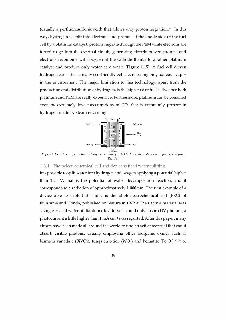
(usually a perfluorosulfonic acid) that allows only proton migration.74 In this
way, hydrogen is split into electrons and protons at the anode side of the fuel
cell by a platinum catalyst; protons migrate through the PEM while electrons are
forced to go into the external circuit, generating electric power; protons and
electrons recombine with oxygen at the cathode thanks to another platinum
catalyst and produce only water as a waste (Figure 1.15). A fuel cell driven
hydrogen car is thus a really eco-friendly vehicle, releasing only aqueous vapor
in the environment. The major limitation to this technology, apart from the
production and distribution of hydrogen, is the high cost of fuel cells, since both
platinum and PEM are really expensive. Furthermore, platinum can be poisoned
even by extremely low concentrations of CO, that is commonly present in
hydrogen made by steam reforming.
Figure 1.15. Scheme of a proton exchange membrane (PEM) fuel cell. Reproduced with permission from
Ref. 72.
1.3.1 Photoelectrochemical cell and dye-sensitized water splitting
It is possible to split water into hydrogen and oxygen applying a potential higher
than 1.23 V, that is the potential of water decomposition reaction, and it
corresponds to a radiation of approximatively 1 000 nm. The first example of a
device able to exploit this idea is the photoelectrochemical cell (PEC) of
Fujishima and Honda, published on Nature in 1972.76 Their active material was
a single crystal wafer of titanium dioxide, so it could only absorb UV photons; a
photocurrent a little higher than 1 mA cm-2 was reported. After this paper, many
efforts have been made all around the world to find an active material that could
absorb visible photons, usually employing other inorganic oxides such as
bismuth vanadate (BiVO4), tungsten oxide (WO3) and hematite (Fe2O3),77-79 or
40
more efficient multijunction electrodes,80 but generally they absorb only
wavelengths shorter than 500 nm, exhibit poor hole transport properties, and
require large bias voltages. Instead, anchoring a dye to an oxide such as TiO2
allows a fine tuning of absorbance and electrochemical properties in order to
match both solar spectrum and the other components of the device. The final
aim is to assemble a system mimicking the natural photosynthesis in plants, a
very complex process whose function is not an efficient energy conversion, but
to let plants survive and reproduce. The photosynthesis efficiency in full light is
in fact only 1-3%.81-84 The dye-sensitizing approach resembles what has been
done also in DSSC, decoupling light absorption, catalytic and transport
functions of the electrode. Actually, DSSCs can be considered a particular class
of PEC, where the anode reaction is simply the reverse of the cathode reaction
and the cell generates electricity; in fact, DSSCs are known also as regenerative
PEC. In a water splitting PEC instead, the anodic reaction is different from the
cathodic one and oxygen and hydrogen respectively are produced. A PEC is
constituted by two electrodes, anode and cathode, that can in principle be both
photoactive, made of a semiconductor absorbing a proper dye (ideally, two dyes
with complementary absorption spectra should be used); on the electrode or in
the aqueous electrolyte solution of each compartment a proper catalyst is
present, either a Water Oxidation Catalyst (WOC) or a Hydrogen Evolution
Catalyst (HEC). The device is completed by wires connecting the electrodes and
the compartments are separated by a proton exchange membrane (PEM) or by
a glass frit that allow only proton transmission. A scheme of a dye-sensitized
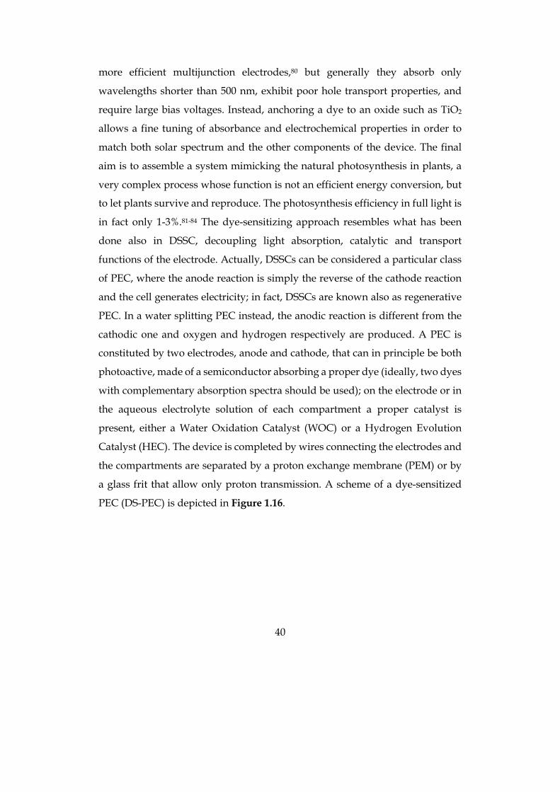
PEC (DS-PEC) is depicted in Figure 1.16.
41
Figure 1.16. Scheme of a dye sensitized photoelectrochemical cell.
The overall reaction taking place in a DS-PEC is the water splitting:
𝐻T𝑂 → 𝐻T +VT𝑂T E=1.23 V
When exposed to sunlight, the dye absorbed onto the photoanode is excited, the
excitation is transferred to the conduction band of the semiconductor, and
electrons flow from anode to cathode through the external circuit. The WOC
oxidizes water producing oxygen and protons and transfers electrons to the dye,
while protons generated by water oxidation migrate through the PEM to the
cathode. There, the process is symmetric with an opposed charge flow, so the
dye, upon absorption of light, transfers electrons to the HEC and returns to its
ground state thanks to electrons coming from the semiconductor and the electric
circuit. The HEC than uses electrons to oxidize protons and evolve hydrogen.
The working mechanism is similar to a DSSC, the difference is that in DSSCs the
dye, after excitation following light absorption, is regenerated by a redox shuttle
that completes the photoelectrochemical circuit, while in DS-PEC, if dyes are
coupled to proper catalysts, water can serve as an electron source, and protons
as electron acceptors for regenerating the oxidized dyes.
Solar-driven PEC water splitting would provide a chemical solution to the
intermittency of PV devices, since a large amount of energy could be stored in
the chemical bonds of hydrogen or hydrocarbon fuels that could be later
released and utilized in fuel cells or internal combustion engines.85 But PEC can
42
go beyond water splitting: they can be used to produce value-added chemicals,
such as H2O2 or H2S2O8,86-87 or biomass-derived chemicals,88 whose economical
values are higher than hydrogen one due to challenges in production or
transportation.
n-type organic dyes for DS-PEC photoanode
Light harvesting in natural photosynthesis is accomplished by a hierarchical
assembly of accessory pigments that funnel their excitation energy to
chlorophyll molecules. Aiming to mimic this natural phenomenon, it is
necessary a dye acting as a sensitizer that absorbs visible light, injects an electron
into the conduction band of a metal oxide semiconductor, usually TiO2, and is
then re-reduced by the water oxidation catalyst, which oxidizes water to give
molecular oxygen and protons. The ideal dye should absorb a significant
fraction of visible spectrum, convert all absorbed photons to electron–hole pairs,
bind persistently to the surface, and have the appropriate redox potential to
drive the catalytic oxidation of water at a WOC. Moreover, the dye should be as
cheap as possible: the requirements are almost the same as DSSCs dyes, so
ruthenium polypyridyl sensitizers and some porphyrins similar to the ones
already tested in DSSCs have been used in DS-PECs,89 but they often use rare
elements, while earth-abundant catalysts and sensitizers will be needed for
large-scale deployment of artificial photosynthesis.90 This suggests that research
should focus the attention on the development of fully organic dyes, that are
terrestrially-abundant and can thus be low cost, just like what has happened in
the extensive research for better DSSCs dyes; a few purely organic sensitizers
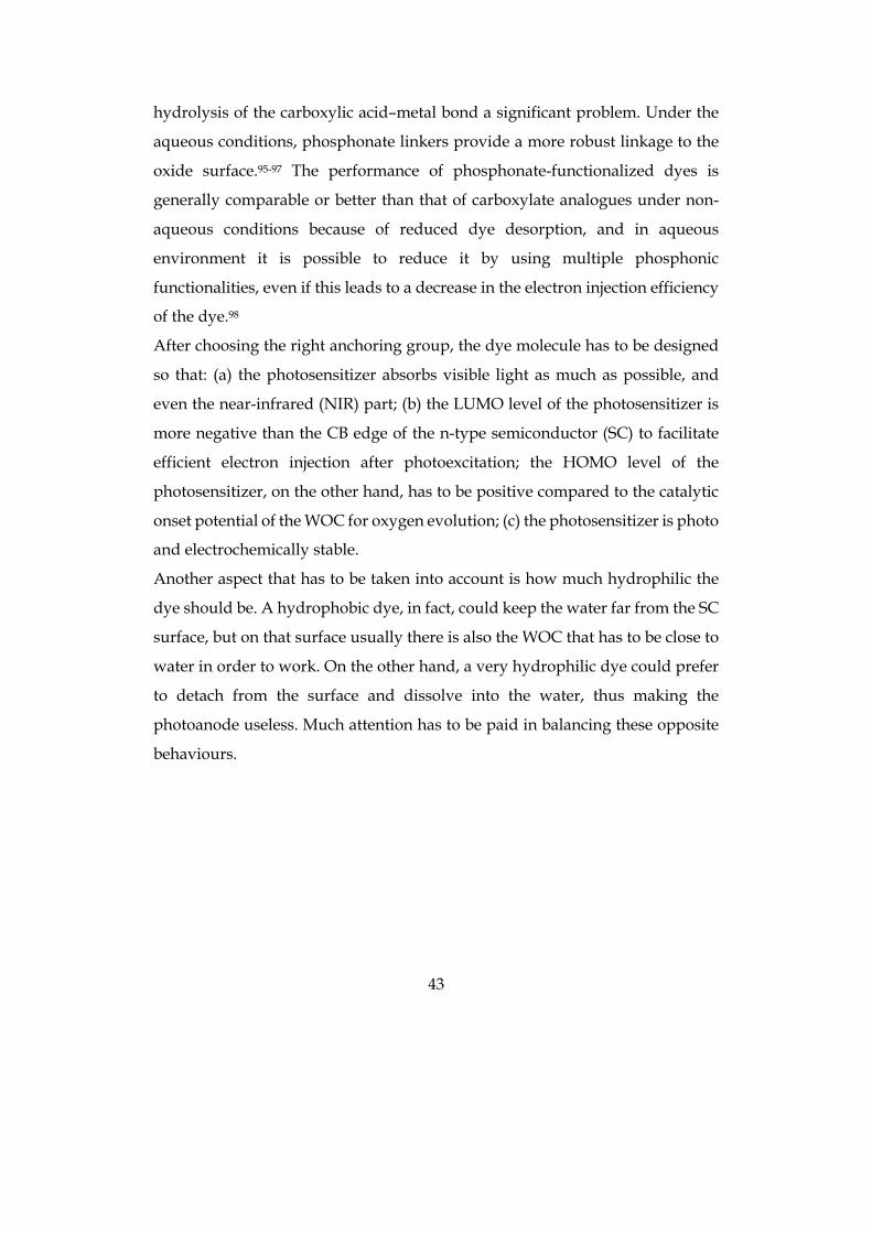
have been published.91-94 Some examples both of metal complexes and of metal-
free dyes are depicted in Figure 1.17.
The chemical bonding of the dye to the high surface area of the semiconductor
oxide is an important and subtle issue. Carboxylic acids are the most frequently
used linking groups in dye-sensitized solar cells (DSSCs), but photoanodes for
water splitting necessarily operate in solutions that contain water, making
43
hydrolysis of the carboxylic acid–metal bond a significant problem. Under the
aqueous conditions, phosphonate linkers provide a more robust linkage to the
oxide surface.95-97 The performance of phosphonate-functionalized dyes is
generally comparable or better than that of carboxylate analogues under non-
aqueous conditions because of reduced dye desorption, and in aqueous
environment it is possible to reduce it by using multiple phosphonic
functionalities, even if this leads to a decrease in the electron injection efficiency
of the dye.98
After choosing the right anchoring group, the dye molecule has to be designed
so that: (a) the photosensitizer absorbs visible light as much as possible, and
even the near-infrared (NIR) part; (b) the LUMO level of the photosensitizer is
more negative than the CB edge of the n-type semiconductor (SC) to facilitate
efficient electron injection after photoexcitation; the HOMO level of the
photosensitizer, on the other hand, has to be positive compared to the catalytic
onset potential of the WOC for oxygen evolution; (c) the photosensitizer is photo
and electrochemically stable.
Another aspect that has to be taken into account is how much hydrophilic the
dye should be. A hydrophobic dye, in fact, could keep the water far from the SC
surface, but on that surface usually there is also the WOC that has to be close to
water in order to work. On the other hand, a very hydrophilic dye could prefer
to detach from the surface and dissolve into the water, thus making the
photoanode useless. Much attention has to be paid in balancing these opposite
behaviours.
44
Figure 1.17. Structures of different dyes tested on photoanodes in DS-PECs. Reprinted from Ref. 89,
Copyright 2018, with permission from Elsevier.
WOC for the anodic compartment
The preparation of a photoanode for a PEC device is pretty similar to the one
used to prepare the photoanode in DSSC cells. The big difference is that, besides
the dye, it is necessary to load a proper catalyst on the SC surface, in particular
a WOC. An ideal WOC must collect four oxidizing equivalents per oxygen
molecule generated, facilitate the formation of molecular oxygen, and be
45
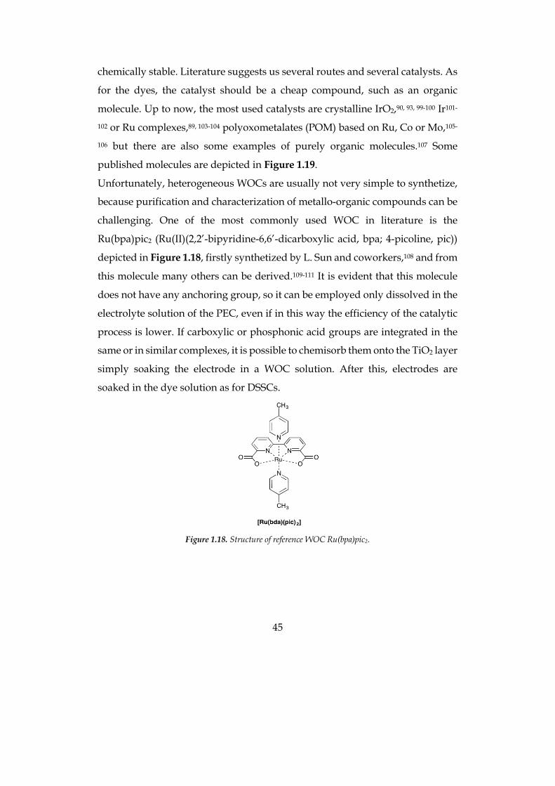
chemically stable. Literature suggests us several routes and several catalysts. As
for the dyes, the catalyst should be a cheap compound, such as an organic
molecule. Up to now, the most used catalysts are crystalline IrO2,90, 93, 99-100 Ir101-
102 or Ru complexes,89, 103-104 polyoxometalates (POM) based on Ru, Co or Mo,105-
106 but there are also some examples of purely organic molecules.107 Some
published molecules are depicted in Figure 1.19.
Unfortunately, heterogeneous WOCs are usually not very simple to synthetize,
because purification and characterization of metallo-organic compounds can be
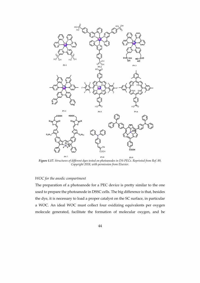
challenging. One of the most commonly used WOC in literature is the
Ru(bpa)pic2 (Ru(II)(2,2’-bipyridine-6,6’-dicarboxylic acid, bpa; 4-picoline, pic))
depicted in Figure 1.18, firstly synthetized by L. Sun and coworkers,108 and from
this molecule many others can be derived.109-111 It is evident that this molecule
does not have any anchoring group, so it can be employed only dissolved in the
electrolyte solution of the PEC, even if in this way the efficiency of the catalytic
process is lower. If carboxylic or phosphonic acid groups are integrated in the
same or in similar complexes, it is possible to chemisorb them onto the TiO2 layer
simply soaking the electrode in a WOC solution. After this, electrodes are
soaked in the dye solution as for DSSCs.
Figure 1.18. Structure of reference WOC Ru(bpa)pic2.
46
Figure 1.19. Structures of some water oxidation catalysts published for using in DS-PEC. Reprinted from
Ref. 89, Copyright 2018, with permission from Elsevier.
Dye-catalyst dyad: one molecule makes it all
It is possible to covalently attach the dye with the anchoring group and the WOC
in one single molecule. This follows the hypothesis that a covalent linkage will
ensure that the WOC is always in close proximity to the dye-sensitizer. This
should lead to rapid electron transfer from the WOC to the dye after its photo-
47
oxidization due to electron injection into the TiO2 CB. In fact, charge
recombination reactions are usually much faster than the difficult multi-electron
water oxidation process, so that charges generated by light absorption are lost
before electrons can be transferred to the CB of TiO2 and holes to the WOC. The
use of a dyad would also simplify the realization of the device since just one
molecule has to be absorbed onto the semiconductor surface, but the synthesis
of such a system is far more complex than that of the two single molecules of
dye and WOC. Up to now, few examples of dyad for water oxidation are present
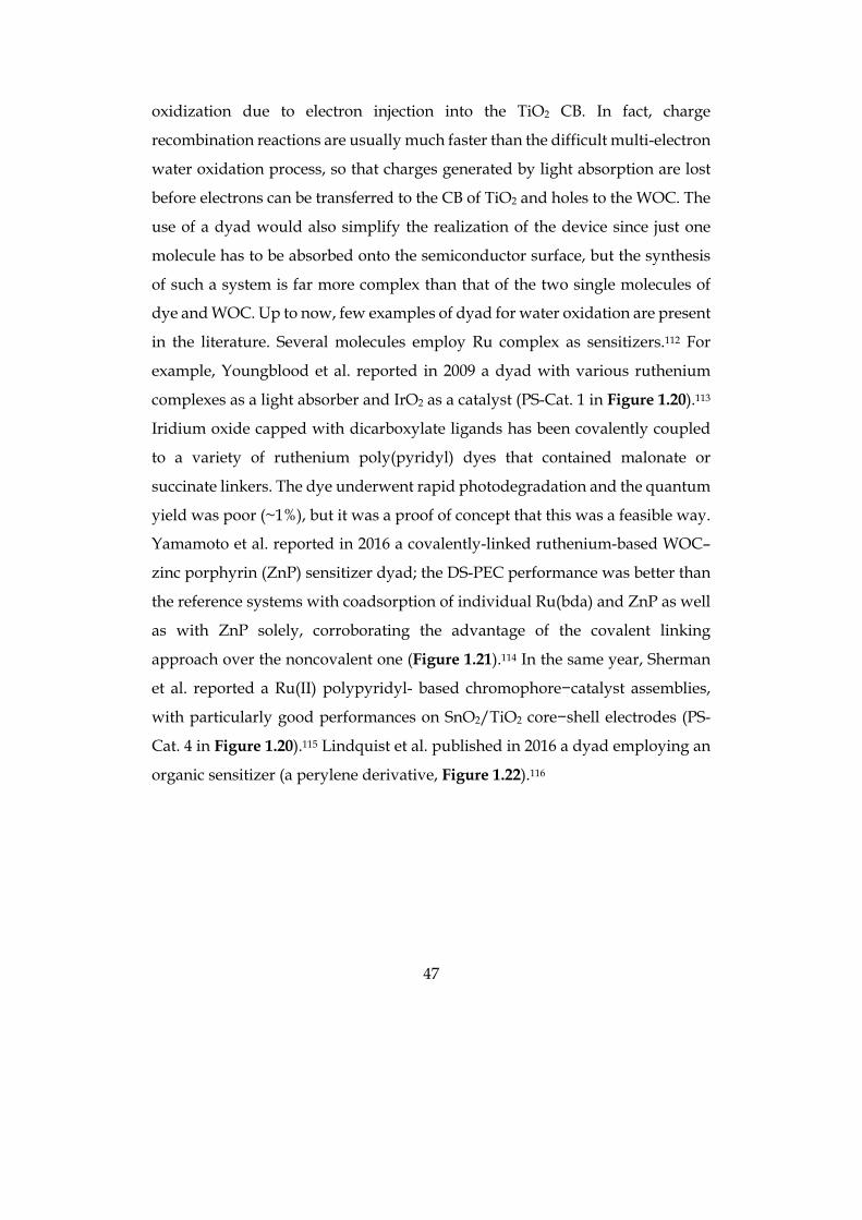
in the literature. Several molecules employ Ru complex as sensitizers.112 For
example, Youngblood et al. reported in 2009 a dyad with various ruthenium
complexes as a light absorber and IrO2 as a catalyst (PS-Cat. 1 in Figure 1.20).113
Iridium oxide capped with dicarboxylate ligands has been covalently coupled
to a variety of ruthenium poly(pyridyl) dyes that contained malonate or
succinate linkers. The dye underwent rapid photodegradation and the quantum
yield was poor (~1%), but it was a proof of concept that this was a feasible way.
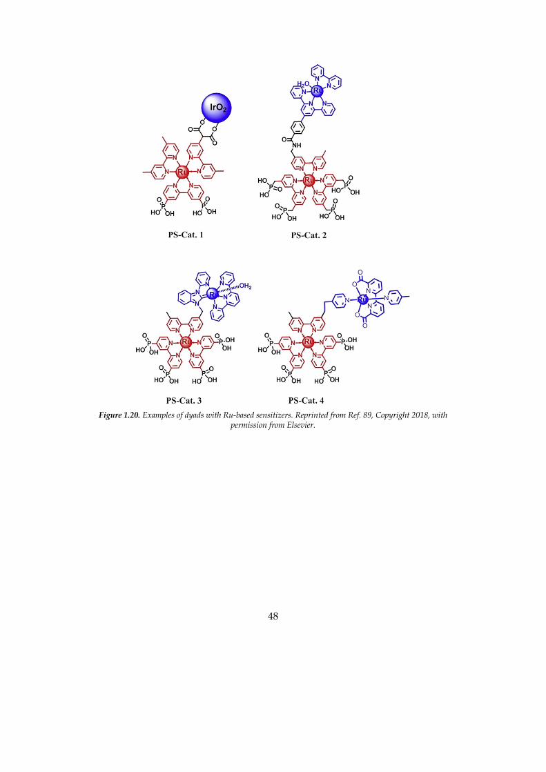
Yamamoto et al. reported in 2016 a covalently-linked ruthenium-based WOC–
zinc porphyrin (ZnP) sensitizer dyad; the DS-PEC performance was better than
the reference systems with coadsorption of individual Ru(bda) and ZnP as well
as with ZnP solely, corroborating the advantage of the covalent linking
approach over the noncovalent one (Figure 1.21).114 In the same year, Sherman
et al. reported a Ru(II) polypyridyl- based chromophore−catalyst assemblies,
with particularly good performances on SnO2/TiO2 core−shell electrodes (PS-
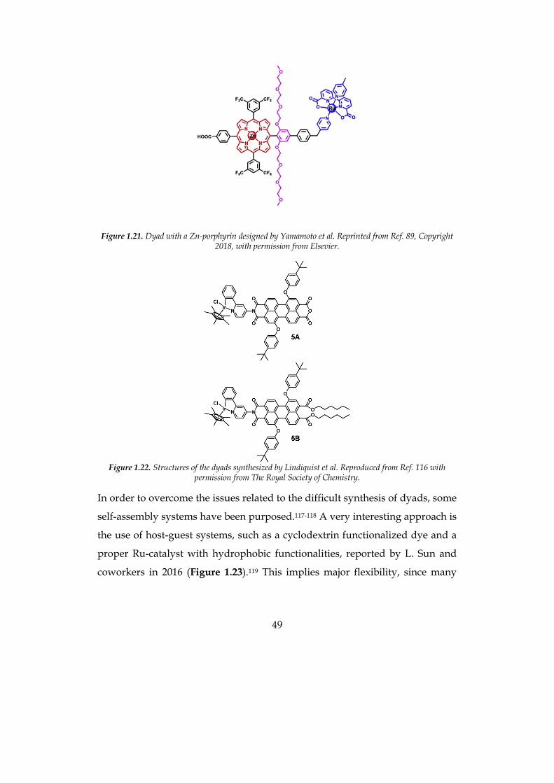
Cat. 4 in Figure 1.20).115 Lindquist et al. published in 2016 a dyad employing an
organic sensitizer (a perylene derivative, Figure 1.22).116
48
Figure 1.20. Examples of dyads with Ru-based sensitizers. Reprinted from Ref. 89, Copyright 2018, with
permission from Elsevier.
49
Figure 1.21. Dyad with a Zn-porphyrin designed by Yamamoto et al. Reprinted from Ref. 89, Copyright 2018, with permission from Elsevier.
Figure 1.22. Structures of the dyads synthesized by Lindiquist et al. Reproduced from Ref. 116 with
permission from The Royal Society of Chemistry.
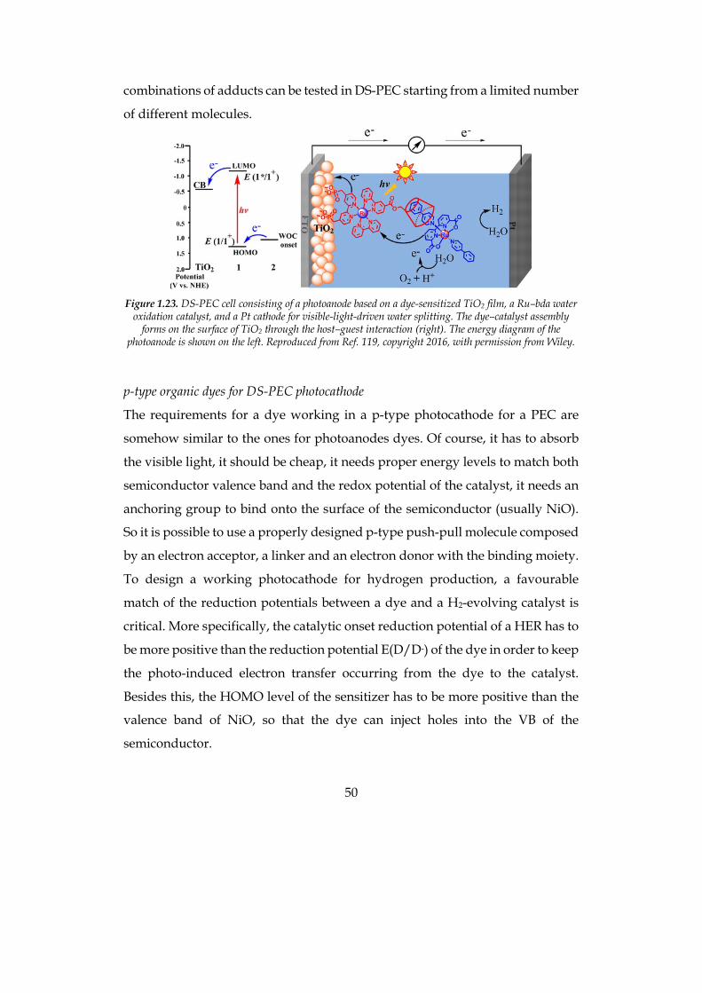
In order to overcome the issues related to the difficult synthesis of dyads, some
self-assembly systems have been purposed.117-118 A very interesting approach is
the use of host-guest systems, such as a cyclodextrin functionalized dye and a
proper Ru-catalyst with hydrophobic functionalities, reported by L. Sun and
coworkers in 2016 (Figure 1.23).119 This implies major flexibility, since many
50
combinations of adducts can be tested in DS-PEC starting from a limited number
of different molecules.
Figure 1.23. DS-PEC cell consisting of a photoanode based on a dye-sensitized TiO2 film, a Ru–bda water
oxidation catalyst, and a Pt cathode for visible-light-driven water splitting. The dye–catalyst assembly forms on the surface of TiO2 through the host–guest interaction (right). The energy diagram of the
photoanode is shown on the left. Reproduced from Ref. 119, copyright 2016, with permission from Wiley.
p-type organic dyes for DS-PEC photocathode
The requirements for a dye working in a p-type photocathode for a PEC are
somehow similar to the ones for photoanodes dyes. Of course, it has to absorb
the visible light, it should be cheap, it needs proper energy levels to match both
semiconductor valence band and the redox potential of the catalyst, it needs an
anchoring group to bind onto the surface of the semiconductor (usually NiO).
So it is possible to use a properly designed p-type push-pull molecule composed
by an electron acceptor, a linker and an electron donor with the binding moiety.
To design a working photocathode for hydrogen production, a favourable
match of the reduction potentials between a dye and a H2-evolving catalyst is
critical. More specifically, the catalytic onset reduction potential of a HER has to
be more positive than the reduction potential E(D/D-) of the dye in order to keep
the photo-induced electron transfer occurring from the dye to the catalyst.
Besides this, the HOMO level of the sensitizer has to be more positive than the
valence band of NiO, so that the dye can inject holes into the VB of the
semiconductor.
51
Photoelectrode stability for water splitting is another challenge. Ideally, low pH
is favourable for improving kinetics of hydrogen production on the deficient
photocathode side and allowing proton conducting membranes to be used to
separate each half cell. Thus it is crucial that the photocathode side is stable in
acidic conditions because local pH changes from the water oxidation reaction
can cause dye degradation and desorption even at neutral pH. Y. Wu and
coworkers reported an innovative dye inspired by the natural membrane-
enabled subcellular compartmentation: they used an organic donor−acceptor
dye that prevents both dye desorption and semiconductor degradation by
mimicking the hydrophobic/hydrophilic properties of lipid bilayer
membranes.120 The molecule, denoted as BH4, is an organic push-double-pull
dye (D−π−2A) that consists of a triphenylamine (TPA) donor moiety connected
to two perylenemonoimide (PMI) acceptor groups by head-to-tail oligio-3-
hexylthiophene-conjugated π-linker groups. The donor group layer, which
contains the carboxylic acid functional group for loading onto NiO, is protected
from the highly protic aqueous electrolyte (1 M HCl, pH 0) by the canopy of
hydrophobic hexyl groups above it in the thiophene linkers. The PMI groups are
located above the canopy of hydrophobic hexyl groups and act as the head layer
whereby the aqueous electrolyte can interact. Upon photoexcitation, an electron
can move from the donor (TPA) to the acceptors (PMI) whereby the charge-
separated state is protected from charge recombination with NiO by the length
of oligothiophene π linker, which is between the donor and acceptor. Coupled
with a cubane molybdenum sulphide cluster, [Mo3S4]4+, dissolved in the
electrolyte solution as the hydrogen evolving catalyst, this system shows great
stability and impressive current densities (about 180 µA/cm2, one order of
magnitude higher than the usually reported ones). This suggests to use bulky
hydrophobic sensitizers in order to obtain the best results both in stability and
efficiency of the photocathode.
HEC for the cathodic compartment
52
As for photoanodes for DS-PECs, photocathodes preparation is similar to active
photocathodes for DSSCs. Unfortunately, this field had been less investigated
than the anodic counterpart, so not much literature is present for this argument.
Also in this case it is necessary to adsorb on a semiconductor (usually NiO) both
the dye and the catalyst.
In order to see if the system could work as a photocathode, it is possible to use
a sacrificial electron donor such as triethanolamine (TEOA) in a homogeneous
system with the dye and the catalyst dissolved in a proper solvent. If light driven
H2-evolution is detected, the preparation of a photocathode with immobilized
dye and catalyst is feasible.
The photocathode can be realized by incorporating the dye and the catalyst into
a nanostructured NiO-based photoactive cathode. The photocathode can be
assembled first by sensitization of a prepared nano-structured NiO film on
conducting glass with the dye, followed by direct deposition of a solution of the
catalyst. The photocathode can then be explored as a working electrode in a
standard three-electrode cell with a proper reference electrode (e.g. Ag/AgCl)
and a counter electrode (e.g. a platinum wire).
The tandem DS-PEC: integration of photoanode and photocathode in the same device
Up to now, research has focused on PEC devices with a DS-photoanode and a
passive Pt-wire as cathode; platinum is a noble metal, so this is of course an
expensive system, the ideal solution would be to replace platinum with an active
photocathode. In this way, the device would be cheaper and, in principle, it
could show better performances and efficiency: both electrodes would contain a
dye and a catalyst, so they would both actively participate to the water splitting
process by absorbing different portions of the solar spectrum. A few example
are present in the literature of such a device, but they employ metallo-organic
dyes or inorganic oxides.121-122
L. Sun et al. recently demonstrated that a device with both anode and cathode
sensitized by purely organic dyes is feasible, with a design similar to tandem
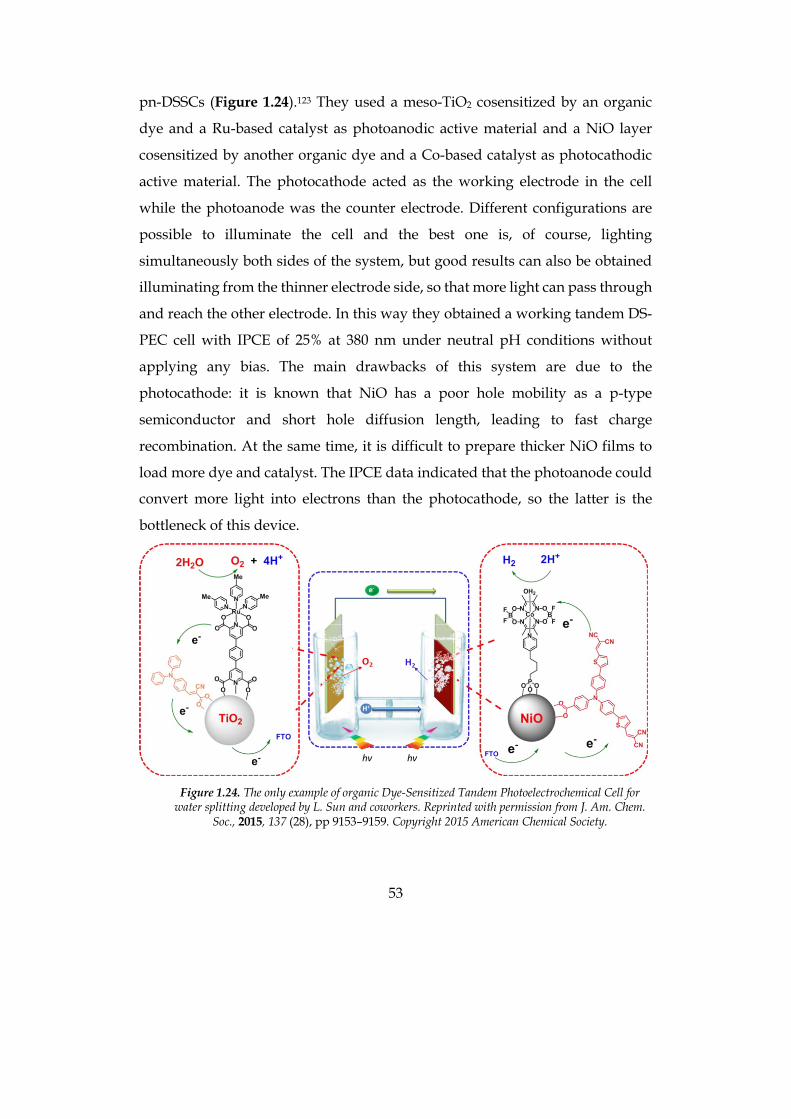
53
pn-DSSCs (Figure 1.24).123 They used a meso-TiO2 cosensitized by an organic
dye and a Ru-based catalyst as photoanodic active material and a NiO layer
cosensitized by another organic dye and a Co-based catalyst as photocathodic
active material. The photocathode acted as the working electrode in the cell
while the photoanode was the counter electrode. Different configurations are
possible to illuminate the cell and the best one is, of course, lighting
simultaneously both sides of the system, but good results can also be obtained
illuminating from the thinner electrode side, so that more light can pass through
and reach the other electrode. In this way they obtained a working tandem DS-
PEC cell with IPCE of 25% at 380 nm under neutral pH conditions without
applying any bias. The main drawbacks of this system are due to the
photocathode: it is known that NiO has a poor hole mobility as a p-type
semiconductor and short hole diffusion length, leading to fast charge
recombination. At the same time, it is difficult to prepare thicker NiO films to
load more dye and catalyst. The IPCE data indicated that the photoanode could
convert more light into electrons than the photocathode, so the latter is the
bottleneck of this device.
Figure 1.24. The only example of organic Dye-Sensitized Tandem Photoelectrochemical Cell for
water splitting developed by L. Sun and coworkers. Reprinted with permission from J. Am. Chem. Soc., 2015, 137 (28), pp 9153–9159. Copyright 2015 American Chemical Society.
54
1.3.2 Working principles and characterization of a DS-PEC
The standard potential ∆E° of water splitting or water electrolysis to H2 and O2
is 1.23 V at any pH.
𝐻T𝑂 → 𝐻T +12𝑂T
From the reaction stoichiometry, the volume of produced hydrogen is twice that
of oxygen. In energetic terms, water splitting requires a free energy ∆G° = -nF
∆E° (where F is the Faraday constant, 96485.3365 C mol-1). For the splitting of 1
mol of H2O to 1 mol of H2 and 0.5 mol of O2, n is equal to 2 electrons and ∆G° =
-2 ´ 96485 C mol-1 ´ -1.23 J C-1 = 237 kJ mol-1 H2O or ∆G° = 2.46 eV mol-1 H2O
(with 1 eV = 96.48 kJ mol-1). Accordingly, for each electron involved in the redox
reaction, the free energy is 1.23 eV. Water splitting is a multi-electronic (2
electrons per each molecule of hydrogen and 4 electrons per each molecule of
oxygen evolved), multi-atomic thermodynamic energy demanding, and
kinetically hampered process with a high activation barrier. Thermodynamic
losses and overpotentials associated to the reaction kinetics increase the voltage
required for water splitting to higher values, up to 1.8 - 2.0 V, the typical voltage
at which commercial electrolysers operate.124
In order to let the water splitting reaction happen, it is possible to use a
photoelectrochemical cell employing both photoanode and photocathode
(tandem configuration) or focusing only on one electrode. In the following work
only active photoanodes have been tested, assembled in a PEC like the one
sketched in Figure 1.25. The photoanode is the working electrode (WE) of the
cell, the counter electrode (CE) is a platinum wire where protons are reduced to
hydrogen and the pseudo-reference electrode (RE) is a Ag/AgCl electrode. The
cell is filled with a phosphate buffer solution (PBS) containing the sacrificial
electron donor or the water oxidation catalyst. Anodic and cathodic
compartments are separated by a proton exchange membrane (PEM) made with
Nafion® membrane, that allows only protons to move from the anode to the
cathode.
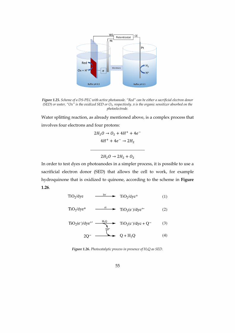
55
Figure 1.25. Scheme of a DS-PEC with active photoanode. “Red” can be either a sacrificial electron donor (SED) or water, “Ox” is the oxidized SED or O2, respectively. π is the organic sensitizer absorbed on the
photoelectrode.
Water splitting reaction, as already mentioned above, is a complex process that
involves four electrons and four protons:
2𝐻T𝑂 → 𝑂T + 4𝐻W + 4𝑒X
4𝐻W + 4𝑒X → 2𝐻T
_________________________
2𝐻T𝑂 → 2𝐻T + 𝑂T
In order to test dyes on photoanodes in a simpler process, it is possible to use a
sacrificial electron donor (SED) that allows the cell to work, for example
hydroquinone that is oxidized to quinone, according to the scheme in Figure
1.26.
Figure 1.26. Photocatalytic process in presence of H2Q as SED.
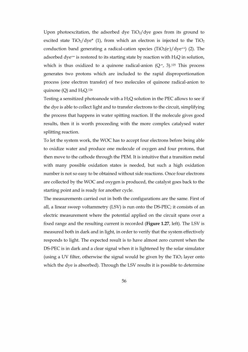
56
Upon photoexcitation, the adsorbed dye TiO2/dye goes from its ground to
excited state TiO2/dye* (1), from which an electron is injected to the TiO2
conduction band generating a radical-cation species (TiO2(e-)/dye+•) (2). The
adsorbed dye+• is restored to its starting state by reaction with H2Q in solution,
which is thus oxidized to a quinone radical-anion (Q-•, 3).125 This process
generates two protons which are included to the rapid disproportionation
process (one electron transfer) of two molecules of quinone radical-anion to
quinone (Q) and H2Q.126
Testing a sensitized photoanode with a H2Q solution in the PEC allows to see if
the dye is able to collect light and to transfer electrons to the circuit, simplifying
the process that happens in water spitting reaction. If the molecule gives good
results, then it is worth proceeding with the more complex catalysed water
splitting reaction.
To let the system work, the WOC has to accept four electrons before being able
to oxidize water and produce one molecule of oxygen and four protons, that
then move to the cathode through the PEM. It is intuitive that a transition metal
with many possible oxidation states is needed, but such a high oxidation
number is not so easy to be obtained without side reactions. Once four electrons
are collected by the WOC and oxygen is produced, the catalyst goes back to the
starting point and is ready for another cycle.
The measurements carried out in both the configurations are the same. First of
all, a linear sweep voltammetry (LSV) is run onto the DS-PEC; it consists of an
electric measurement where the potential applied on the circuit spans over a
fixed range and the resulting current is recorded (Figure 1.27, left). The LSV is
measured both in dark and in light, in order to verify that the system effectively
responds to light. The expected result is to have almost zero current when the
DS-PEC is in dark and a clear signal when it is lightened by the solar simulator
(using a UV filter, otherwise the signal would be given by the TiO2 layer onto
which the dye is absorbed). Through the LSV results it is possible to determine
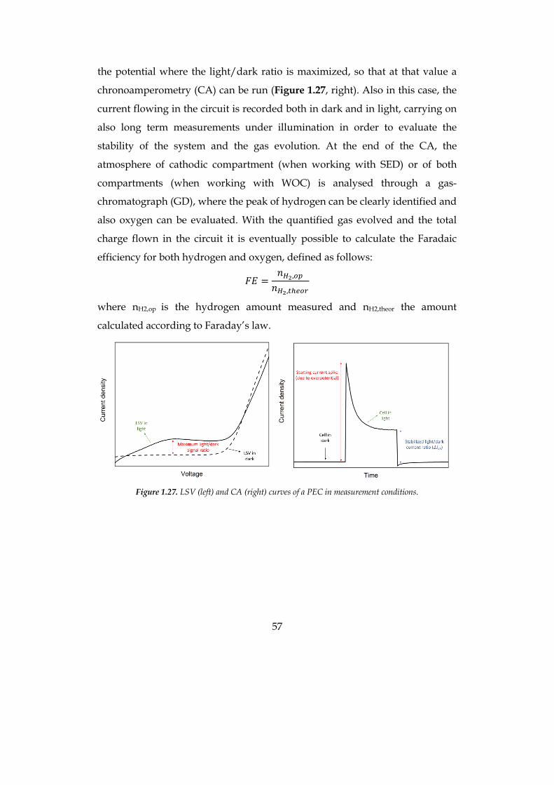
57
the potential where the light/dark ratio is maximized, so that at that value a
chronoamperometry (CA) can be run (Figure 1.27, right). Also in this case, the
current flowing in the circuit is recorded both in dark and in light, carrying on
also long term measurements under illumination in order to evaluate the
stability of the system and the gas evolution. At the end of the CA, the
atmosphere of cathodic compartment (when working with SED) or of both
compartments (when working with WOC) is analysed through a gas-
chromatograph (GD), where the peak of hydrogen can be clearly identified and
also oxygen can be evaluated. With the quantified gas evolved and the total
charge flown in the circuit it is eventually possible to calculate the Faradaic
efficiency for both hydrogen and oxygen, defined as follows:
𝐹𝐸 =𝑛YZ,&C𝑛YZ,(\]&^
where nH2,op is the hydrogen amount measured and nH2,theor the amount
calculated according to Faraday’s law.
Figure 1.27. LSV (left) and CA (right) curves of a PEC in measurement conditions.
58
1.4 Bibliography
1. Grätzel, M., ”Photoelectrochemical cells”. Nature 2001, 414, 338, doi: 10.1038/35104607
2. Chiras, D. D., Environmental Science. 9 ed.; Jones & Bartlett Publishers: 2012.
3. Armaroli, N.; Balzani, V., ”Solar Electricity and Solar Fuels: Status and Perspectives in the Context of the Energy Transition”. Chem. Eur. J. 2016, 22, 32-57, doi: 10.1002/chem.201503580
4. Webber, M. E., ”More Food, Less Energy”. SciAm 2012, 306, 74-79, doi: 10.1038/scientificamerican0112-74
5. Murphy, D. J.; Hall, C. A. S.; Dale, M.; Cleveland, C., ”Order from Chaos: A Preliminary Protocol for Determining the EROI of Fuels”. Sustainability 2011, 3, doi: 10.3390/su3101888
6. Nicola Armaroli, V. B., Energy for a Sustainable World: From the Oil Age to a Sun-Powered Future. Wiley-VCH Verlag GmbH & Co. KGaA 2011.
7. ”British Petroleum, BP Statistical Review of World Energy 2015”. http://www.bp.com.
8. Service, R. F., ”Is It Time to Shoot for the Sun?”. Sci 2005, 309, 548, doi:
9. REN21, Renewables 2018 Global Status Report. 2018 ed.; 2018.
10. NREL American Society for Testing.2010.”Terrestrial Reference Spectra for Photovoltaic Performance Evaluation (ASTM G-173-03)”. http://rredc.nrel.gov/solar/spectra/am1.5/.
11. Chapin, D. M.; Fuller, C. S.; Pearson, G. L., ”A New Silicon p-n Junction Photocell for Converting Solar Radiation into Electrical Power”. JAP 1954, 25, 676-677, doi: 10.1063/1.1721711
59
12. EnergyTrend TrendForce Corp. .”PV Price Quotes”. https://pv.energytrend.com/pricequotes.html (accessed September 2018).
13. NREL, Best Research-Cell Efficiencies. http://www.nrel.gov, 2018.
14. Lee, C.-P.; Lin, C.-A.; Wei, T.-C.; Tsai, M.-L.; Meng, Y.; Li, C.-T.; Ho, K.-C.; Wu, C.-I.; Lau, S.-P.; He, J.-H., ”Economical low-light photovoltaics by using the Pt-free dye-sensitized solar cell with graphene dot/PEDOT:PSS counter electrodes”. Nano Energy 2015, 18, 109-117, doi: https://doi.org/10.1016/j.nanoen.2015.10.008
15. Rasheduzzaman, M.; Pillai, P. B.; Mendoza, A. N. C.; Souza, M. M. D. In A study of the performance of solar cells for indoor autonomous wireless sensors, 2016 10th International Symposium on Communication Systems, Networks and Digital Signal Processing (CSNDSP), 20-22 July 2016; 2016; pp 1-6.
16. Desilvestro, J.; Graetzel, M.; Kavan, L.; Moser, J.; Augustynski, J., ”Highly efficient sensitization of titanium dioxide”. J. Am. Chem. Soc. 1985, 107, 2988-2990, doi: 10.1021/ja00296a035
17. Vlachopoulos, N.; Liska, P.; Augustynski, J.; Graetzel, M., ”Very efficient visible light energy harvesting and conversion by spectral sensitization of high surface area polycrystalline titanium dioxide films”. J. Am. Chem. Soc. 1988, 110, 1216-1220, doi: 10.1021/ja00212a033
18. O'Regan, B.; Grätzel, M., ”A low-cost, high-efficiency solar cell based on dye-sensitized colloidal TiO2 films”. Nature 1991, 353, 737-740, doi:
19. Nazeeruddin, M. K.; Kay, A.; Rodicio, I.; Humphry-Baker, R.; Mueller, E.; Liska, P.; Vlachopoulos, N.; Graetzel, M., ”Conversion of light to electricity by cis-X2bis(2,2'-bipyridyl-4,4'-dicarboxylate)ruthenium(II) charge-transfer sensitizers (X = Cl-, Br-, I-, CN-, and SCN-) on nanocrystalline titanium dioxide electrodes”. J. Am. Chem. Soc. 1993, 115, 6382-6390, doi: 10.1021/ja00067a063
20. Nazeeruddin, M. K.; Zakeeruddin, S. M.; Humphry-Baker, R.; Jirousek, M.; Liska, P.; Vlachopoulos, N.; Shklover, V.; Fischer, C.-H.; Grätzel, M., ”Acid−Base Equilibria of (2,2‘-Bipyridyl-4,4‘-dicarboxylic acid)ruthenium(II) Complexes and the Effect of Protonation on Charge-Transfer Sensitization of Nanocrystalline Titania”. Inorg. Chem. 1999, 38, 6298-6305, doi: 10.1021/ic990916a
60
21. Nazeeruddin, M. K.; Humphry-Baker, R.; Liska, P.; Grätzel, M., ”Investigation of Sensitizer Adsorption and the Influence of Protons on Current and Voltage of a Dye-Sensitized Nanocrystalline TiO2 Solar Cell”. J. Phys. Chem. B 2003, 107, 8981-8987, doi: 10.1021/jp022656f
22. Wang, P.; Zakeeruddin, S. M.; Moser, J. E.; Nazeeruddin, M. K.; Sekiguchi, T.; Grätzel, M., ”A stable quasi-solid-state dye-sensitized solar cell with an amphiphilic ruthenium sensitizer and polymer gel electrolyte”. Nature Materials 2003, 2, 402, doi: 10.1038/nmat904
23. Abbotto, A.; Barolo, C.; Bellotto, L.; Angelis, F. D.; Grätzel, M.; Manfredi, N.; Marinzi, C.; Fantacci, S.; Yum, J.-H.; Nazeeruddin, M. K., ”Electron-rich heteroaromatic conjugated bipyridine based ruthenium sensitizer for efficient dye-sensitized solar cells”. Chem. Commun. 2008, 5318-5320, doi: 10.1039/B811378E
24. Abbotto, A.; Sauvage, F.; Barolo, C.; De Angelis, F.; Fantacci, S.; Graetzel, M.; Manfredi, N.; Marinzi, C.; Nazeeruddin, M. K., ”Panchromatic ruthenium sensitizer based on electron-rich heteroarylvinylene π-conjugated quaterpyridine for dye-sensitized solar cells”. Dalton Transactions 2011, 40, 234-242, doi: 10.1039/C0DT01190H
25. Chen, C.-Y.; Wu, S.-J.; Wu, C.-G.; Chen, J.-G.; Ho, K.-C., ”A Ruthenium Complex with Superhigh Light-Harvesting Capacity for Dye-Sensitized Solar Cells”. Angew. Chem. Int. Ed. 2006, 45, 5822-5825, doi: 10.1002/anie.200601463
26. Coluccini, C.; Manfredi, N.; Calderon, E. H.; Salamone, M. M.; Ruffo, R.; Roberto, D.; Lobello, M. G.; De Angelis, F.; Abbotto, A., ”Photophysical and Electrochemical Properties of Thiophene-Based 2-Arylpyridines”. Eur. J. Org. Chem. 2011, 2011, 5587-5598, doi: 10.1002/ejoc.201100651
27. Sauvage, F.; Decoppet, J.-D.; Zhang, M.; Zakeeruddin, S. M.; Comte, P.; Nazeeruddin, M.; Wang, P.; Grätzel, M., ”Effect of Sensitizer Adsorption Temperature on the Performance of Dye-Sensitized Solar Cells”. J. Am. Chem. Soc. 2011, 133, 9304-9310, doi: 10.1021/ja110541t
28. Shi, D.; Pootrakulchote, N.; Li, R.; Guo, J.; Wang, Y.; Zakeeruddin, S. M.; Grätzel, M.; Wang, P., ”New Efficiency Records for Stable Dye-Sensitized Solar Cells with Low-Volatility and Ionic Liquid Electrolytes”. J. Phys. Chem. C 2008, 112, 17046-17050, doi: 10.1021/jp808018h
61
29. Hagfeldt, A.; Boschloo, G.; Sun, L.; Kloo, L.; Pettersson, H., ”Dye-Sensitized Solar Cells”. Chem. Rev. 2010, 110, 6595-6663, doi: 10.1021/cr900356p
30. Hao, Y.; Yang, X.; Cong, J.; Tian, H.; Hagfeldt, A.; Sun, L., ”Efficient near infrared D–π–A sensitizers with lateral anchoring group for dye-sensitized solar cells”. Chem. Commun. 2009, 4031-4033, doi: 10.1039/B908396K
31. Mishra, A.; Fischer, M. K. R.; Bäuerle, P., ”Metal-Free Organic Dyes for Dye-Sensitized Solar Cells: From Structure: Property Relationships to Design Rules”. Angew. Chem. Int. Ed. 2009, 48, 2474-2499, doi: 10.1002/anie.200804709
32. Wang, Z.-S.; Cui, Y.; Dan-oh, Y.; Kasada, C.; Shinpo, A.; Hara, K., ”Thiophene-Functionalized Coumarin Dye for Efficient Dye-Sensitized Solar Cells: Electron Lifetime Improved by Coadsorption of Deoxycholic Acid”. J. Phys. Chem. C 2007, 111, 7224-7230, doi: 10.1021/jp067872t
33. Wang, Z.-S.; Koumura, N.; Cui, Y.; Takahashi, M.; Sekiguchi, H.; Mori, A.; Kubo, T.; Furube, A.; Hara, K., ”Hexylthiophene-Functionalized Carbazole Dyes for Efficient Molecular Photovoltaics: Tuning of Solar-Cell Performance by Structural Modification”. Chem. Mater. 2008, 20, 3993-4003, doi: 10.1021/cm8003276
34. Hagberg, D. P.; Yum, J.-H.; Lee, H.; De Angelis, F.; Marinado, T.; Karlsson, K. M.; Humphry-Baker, R.; Sun, L.; Hagfeldt, A.; Grätzel, M.; Nazeeruddin, M. K., ”Molecular Engineering of Organic Sensitizers for Dye-Sensitized Solar Cell Applications”. J. Am. Chem. Soc. 2008, 130, 6259-6266, doi: 10.1021/ja800066y
35. Choi, H.; Baik, C.; Kang, S. O.; Ko, J.; Kang, M.-S.; Nazeeruddin, M. K.; Grätzel, M., ”Highly Efficient and Thermally Stable Organic Sensitizers for Solvent-Free Dye-Sensitized Solar Cells”. Angew. Chem. Int. Ed. 2007, 47, 327-330, doi: 10.1002/anie.200703852
36. Zhang, G.; Bala, H.; Cheng, Y.; Shi, D.; Lv, X.; Yu, Q.; Wang, P., ”High efficiency and stable dye-sensitized solar cells with an organic chromophore featuring a binary π-conjugated spacer”. Chem. Commun. 2009, 2198-2200, doi: 10.1039/B822325D
37. Abbotto, A.; Manfredi, N.; Marinzi, C.; De Angelis, F.; Mosconi, E.; Yum, J.-H.; Xianxi, Z.; Nazeeruddin, M. K.; Gratzel, M., ”Di-branched di-anchoring
62
organic dyes for dye-sensitized solar cells”. Energy Environ. Sci. 2009, 2, 1094-1101, doi: 10.1039/B910654E
38. Abbotto, A.; Leandri, V.; Manfredi, N.; De Angelis, F.; Pastore, M.; Yum, J.-H.; Nazeeruddin, M. K.; Grätzel, M., ”Bis-Donor–Bis-Acceptor Tribranched Organic Sensitizers for Dye-Sensitized Solar Cells”. Eur. J. Org. Chem. 2011, 2011, 6195-6205, doi: 10.1002/ejoc.201100821
39. Leandri, V.; Ruffo, R.; Trifiletti, V.; Abbotto, A., ”Asymmetric Tribranched Dyes: An Intramolecular Cosensitization Approach for Dye-Sensitized Solar Cells”. Eur. J. Org. Chem. 2013, 2013, 6793-6801, doi: 10.1002/ejoc.201300962
40. Manfredi, N.; Cecconi, B.; Abbotto, A., ”Multi-Branched Multi-Anchoring Metal-Free Dyes for Dye-Sensitized Solar Cells”. Eur. J. Org. Chem. 2014, 2014, 7069-7086, doi: 10.1002/ejoc.201402422
41. Yella, A.; Lee, H.-W.; Tsao, H. N.; Yi, C.; Chandiran, A. K.; Nazeeruddin, M. K.; Diau, E. W.-G.; Yeh, C.-Y.; Zakeeruddin, S. M.; Grätzel, M., ”Porphyrin-Sensitized Solar Cells with Cobalt (II/III)–Based Redox Electrolyte Exceed 12 Percent Efficiency”. Sci 2011, 334, 629, doi:
42. Kakiage, K.; Aoyama, Y.; Yano, T.; Oya, K.; Fujisawa, J.-i.; Hanaya, M., ”Highly-efficient dye-sensitized solar cells with collaborative sensitization by silyl-anchor and carboxy-anchor dyes”. Chem. Commun. 2015, 51, 15894-15897, doi: 10.1039/C5CC06759F
43. Wu, J.; Lan, Z.; Lin, J.; Huang, M.; Huang, Y.; Fan, L.; Luo, G., ”Electrolytes in Dye-Sensitized Solar Cells”. Chem. Rev. 2015, 115, 2136-2173, doi: 10.1021/cr400675m
44. Yun, S.; Freitas, J. N.; Nogueira, A. F.; Wang, Y.; Ahmad, S.; Wang, Z.-S., ”Dye-sensitized solar cells employing polymers”. Prog. Polym. Sci. 2016, 59, 1-40, doi: https://doi.org/10.1016/j.progpolymsci.2015.10.004
45. Liu, Y.; Hagfeldt, A.; Xiao, X. R.; Lindquist, S. E., ”Investigation of influence of redox species on the interfacial energetics of a dye-sensitized nanoporous TiO2 solar cell”. Sol. Energy Mater. Sol. Cells 1998, 55, 267-281, doi: 10.1016/s0927-0248(98)00111-1
63
46. Bella, F.; Gerbaldi, C.; Barolo, C.; Grätzel, M., ”Aqueous dye-sensitized solar cells”. Chem. Soc. Rev. 2015, 44, 3431-3473, doi: 10.1039/C4CS00456F
47. Bella, F.; Galliano, S.; Falco, M.; Viscardi, G.; Barolo, C.; Grätzel, M.; Gerbaldi, C., ”Unveiling iodine-based electrolytes chemistry in aqueous dye-sensitized solar cells”. Chem. Sci. 2016, doi: 10.1039/C6SC01145D
48. Lin, R. Y.-Y.; Wu, F.-L.; Li, C.-T.; Chen, P.-Y.; Ho, K.-C.; Lin, J. T., ”High-Performance Aqueous/Organic Dye-Sensitized Solar Cells Based on Sensitizers Containing Triethylene Oxide Methyl Ether”. ChemSusChem 2015, 8, 2503-2513, doi: 10.1002/cssc.201500589
49. Kaneko, M.; Nomura, T.; Sasaki, C., ”Photoinduced Charge Separation in an Aqueous Phase Using Nanoporous TiO2 Film and a Quasi-Solid Made of Natural Products”. Macromol. Rapid Commun. 2003, 24, 444-446, doi: 10.1002/marc.200390059
50. Kim, D. H.; Losego, M. D.; Hanson, K.; Alibabaei, L.; Lee, K.; Meyer, T. J.; Parsons, G. N., ”Stabilizing chromophore binding on TiO2 for long-term stability of dye-sensitized solar cells using multicomponent atomic layer deposition”. Phys. Chem. Chem. Phys. 2014, 16, 8615-8622, doi: 10.1039/C4CP01130A
51. Leandri, V.; Ellis, H.; Gabrielsson, E.; Sun, L.; Boschloo, G.; Hagfeldt, A., ”An organic hydrophilic dye for water-based dye-sensitized solar cells”. Phys. Chem. Chem. Phys. 2014, 16, 19964-19971, doi: 10.1039/C4CP02774D
52. Choi, H.; Jeong, B.-S.; Do, K.; Ju, M. J.; Song, K.; Ko, J., ”Aqueous electrolyte based dye-sensitized solar cells using organic sensitizers”. New J. Chem. 2013, 37, 329-336, doi: 10.1039/C2NJ40577F
53. Galliano, S.; Bella, F.; Gerbaldi, C.; Falco, M.; Viscardi, G.; Grätzel, M.; Barolo, C., ”Photoanode/Electrolyte Interface Stability in Aqueous Dye-Sensitized Solar Cells”. Energy Technology 2016, 5, 300-311, doi: 10.1002/ente.201600285
54. Xiang, W.; Huang, F.; Cheng, Y.-B.; Bach, U.; Spiccia, L., ”Aqueous dye-sensitized solar cell electrolytes based on the cobalt(ii)/(iii) tris(bipyridine) redox couple”. Energy Environ. Sci. 2013, 6, 121-127, doi: 10.1039/C2EE23317G
64
55. Dong, C.; Xiang, W.; Huang, F.; Fu, D.; Huang, W.; Bach, U.; Cheng, Y.-B.; Li, X.; Spiccia, L., ”Controlling Interfacial Recombination in Aqueous Dye-Sensitized Solar Cells by Octadecyltrichlorosilane Surface Treatment”. Angew. Chem. Int. Ed. 2014, 53, 6933-6937, doi: 10.1002/anie.201400723
56. Ellis, H.; Vlachopoulos, N.; Häggman, L.; Perruchot, C.; Jouini, M.; Boschloo, G.; Hagfeldt, A., ”PEDOT counter electrodes for dye-sensitized solar cells prepared by aqueous micellar electrodeposition”. Electrochim. Acta 2013, 107, 45-51, doi: http://dx.doi.org/10.1016/j.electacta.2013.06.005
57. Bella, F.; Galliano, S.; Falco, M.; Viscardi, G.; Barolo, C.; Grätzel, M.; Gerbaldi, C., ”Approaching truly sustainable solar cells by the use of water and cellulose derivatives”. Green Chem. 2017, 19, 1043-1051, doi: 10.1039/C6GC02625G
58. Kalyanasundaram, K., Dye-sensitized Solar Cells. EFPL Press: 2010.
59. Calogero, G.; Calandra, P.; Irrera, A.; Sinopoli, A.; Citro, I.; Di Marco, G., ”A new type of transparent and low cost counter-electrode based on platinum nanoparticles for dye-sensitized solar cells”. Energy Environ. Sci. 2011, 4, 1838-1844, doi: 10.1039/C0EE00463D
60. Snaith, H. J., ”Estimating the Maximum Attainable Efficiency in Dye-Sensitized Solar Cells”. Adv. Funct. Mater. 2009, 20, 13-19, doi: 10.1002/adfm.200901476
61. Christoph Joseph Brabec, V. D., Jürgen Parisi, Niyazi Serdar Sariciftci, Organic Photovoltaics. Springer-Verlag Berlin Heidelberg: Berlin, 2003.
62. Green, M. A.; Emery, K.; Hishikawa, Y.; Warta, W., ”Solar cell efficiency tables (version 36)”. Progr. Photovolt: Res. Appl. 2010, 18, 346-352, doi: 10.1002/pip.1021
63. Shockley, W.; Queisser, H. J., ”Detailed Balance Limit of Efficiency of p-n Junction Solar Cells”. JAP 1961, 32, 510-519, doi: 10.1063/1.1736034
64. Williams, E.; Sekar, A.; Matteson, S.; Rittmann, B. E., ”Sun-to-Wheels Exergy Efficiencies for Bio-Ethanol and Photovoltaics”. Environ Sci Technol 2015, 49, 6394-6401, doi: 10.1021/es504377b
65
65. Narins, T. P., ”The battery business: Lithium availability and the growth of the global electric car industry”. The Extractive Industries and Society 2017, 4, 321-328, doi: https://doi.org/10.1016/j.exis.2017.01.013
66. Vikström, H.; Davidsson, S.; Höök, M., ”Lithium availability and future production outlooks”. ApEn 2013, 110, 252-266, doi: https://doi.org/10.1016/j.apenergy.2013.04.005
67. Tarascon, J. M.; Armand, M., ”Issues and challenges facing rechargeable lithium batteries”. Nature 2001, 414, 359, doi: 10.1038/35104644
68. Smil, V., Energy at the Crossroads: Global Perspectives and Uncertainties MIT press: Cambridge, MA, 2003.
69. Hammond, A. L., ”Solar Energy: The Largest Resource”. Sci 1972, 177, 1088, doi:
70. Dawson, J. K., ”Prospects for hydrogen as an energy resource”. Nature 1974, 249, 724, doi: 10.1038/249724a0
71. Balzani, V.; Moggi, L.; Manfrin, M. F.; Bolletta, F.; Gleria, M., ”Solar Energy Conversion by Water Photodissociation”. Sci 1975, 189, 852, doi:
72. Armaroli, N.; Balzani, V., ”The Hydrogen Issue”. ChemSusChem 2010, 4, 21-36, doi: 10.1002/cssc.201000182
73. Stone, R., ”Three Gorges Dam: Into the Unknown”. Sci 2008, 321, 628, doi:
74. Handbook of Fuel Cells. Wiley-VCH: Weinheim, 2009; Vol. 3.
75. ”Fuel Cell Basics”. http://www.fchea.org/fuelcells/ (accessed September 2018).
76. Fujishima, A.; Honda, K., ”Electrochemical Photolysis of Water at a Semiconductor Electrode”. Nature 1972, 238, 37-38, doi:
66
77. Liu, X.; Wang, F.; Wang, Q., ”Nanostructure-based WO3 photoanodes for photoelectrochemical water splitting”. Phys. Chem. Chem. Phys. 2012, 14, 7894-7911, doi: 10.1039/C2CP40976C
78. Abdi, F. F.; van de Krol, R., ”Nature and Light Dependence of Bulk Recombination in Co-Pi-Catalyzed BiVO4 Photoanodes”. J. Phys. Chem. C 2012, 116, 9398-9404, doi: 10.1021/jp3007552
79. Sivula, K.; Le Formal, F.; Grätzel, M., ”Solar Water Splitting: Progress Using Hematite (α-Fe2O3) Photoelectrodes”. ChemSusChem 2011, 4, 432-449, doi: 10.1002/cssc.201000416
80. Licht, S.; Wang, B.; Mukerji, S.; Soga, T.; Umeno, M.; Tributsch, H., ”Over 18% solar energy conversion to generation of hydrogen fuel; theory and experiment for efficient solar water splitting”. Int. J. Hydrogen Energy 2001, 26, 653-659, doi: https://doi.org/10.1016/S0360-3199(00)00133-6
81. Nelson, N.; Yocum, C. F., ”STRUCTURE AND FUNCTION OF PHOTOSYSTEMS I AND II”. Annual Review of Plant Biology 2006, 57, 521-565, doi: 10.1146/annurev.arplant.57.032905.105350
82. Beadle, C. L.; Long, S. P., ”Photosynthesis — is it limiting to biomass production?”. Biomass 1985, 8, 119-168, doi: https://doi.org/10.1016/0144-4565(85)90022-8
83. Beale, C. V.; Long, S. P., ”Can perennial C4 grasses attain high efficiencies of radiant energy conversion in cool climates?”. Plant, Cell & Environment 1995, 18, 641-650, doi: 10.1111/j.1365-3040.1995.tb00565.x
84. Chrispeels, M. J. S., David E. , Plants, genes, and crop biotechnology. 2nd ed.; Jones and Bartlett Publisher: Boston, 2002.
85. Jin, S., ”What Else Can Photoelectrochemical Solar Energy Conversion Do Besides Water Splitting and CO2 Reduction?”. ACS Energy Letters 2018, 3, 2610-2612, doi: 10.1021/acsenergylett.8b01800
86. Mase, K.; Yoneda, M.; Yamada, Y.; Fukuzumi, S., ”Efficient Photocatalytic Production of Hydrogen Peroxide from Water and Dioxygen with Bismuth Vanadate and a Cobalt(II) Chlorin Complex”. ACS Energy Letters 2016, 1, 913-919, doi: 10.1021/acsenergylett.6b00415
67
87. Sayama, K., ”Production of High-Value-Added Chemicals on Oxide Semiconductor Photoanodes under Visible Light for Solar Chemical-Conversion Processes”. ACS Energy Letters 2018, 3, 1093-1101, doi: 10.1021/acsenergylett.8b00318
88. Cha, H. G.; Choi, K.-S., ”Combined biomass valorization and hydrogen production in a photoelectrochemical cell”. Nature Chemistry 2015, 7, 328, doi: 10.1038/nchem.2194 https://www.nature.com/articles/nchem.2194#supplementary-information
89. Ding, X.; Zhang, L.; Wang, Y.; Liu, A.; Gao, Y., ”Design of photoanode-based dye-sensitized photoelectrochemical cells assembling with transition metal complexes for visible light-induced water splitting”. Coord. Chem. Rev. 2018, 357, 130-143, doi: https://doi.org/10.1016/j.ccr.2017.10.020
90. Swierk, J. R.; Mallouk, T. E., ”Design and development of photoanodes for water-splitting dye-sensitized photoelectrochemical cells”. Chem. Soc. Rev. 2013, 42, 2357-2387, doi: Doi 10.1039/C2cs35246j
91. Yamamoto, M.; Nishizawa, Y.; Chabera, P.; Li, F.; Pascher, T.; Sundstrom, V.; Sun, L.; Imahori, H., ”Visible light-driven water oxidation with a subporphyrin sensitizer and a water oxidation catalyst”. Chem. Commun. 2016, 52, 13702-13705, doi: 10.1039/C6CC07877J
92. Wee, K.-R.; Sherman, B. D.; Brennaman, M. K.; Sheridan, M. V.; Nayak, A.; Alibabaei, L.; Meyer, T. J., ”An aqueous, organic dye derivatized SnO2/TiO2 core/shell photoanode”. J. Mater. Chem. A 2016, doi: 10.1039/C5TA06678F
93. Swierk, J. R.; Méndez-Hernández, D. D.; McCool, N. S.; Liddell, P.; Terazono, Y.; Pahk, I.; Tomlin, J. J.; Oster, N. V.; Moore, T. A.; Moore, A. L.; Gust, D.; Mallouk, T. E., ”Metal-free organic sensitizers for use in water-splitting dye-sensitized photoelectrochemical cells”. Proc. Natl. Acad. Sci. U.S.A. 2015, 112, 1681-1686, doi: 10.1073/pnas.1414901112
94. Suryani, O.; Higashino, Y.; Mulyana, J. Y.; Kaneko, M.; Hoshi, T.; Shigaki, K.; Kubo, Y., ”A near-infrared organic photosensitizer for use in dye-sensitized photoelectrochemical water splitting”. Chem. Commun. 2017, 53, 6784-6787, doi: 10.1039/C7CC02730C
68
95. Gillaizeau-Gauthier, I.; Odobel, F.; Alebbi, M.; Argazzi, R.; Costa, E.; Bignozzi, C. A.; Qu, P.; Meyer, G. J., ”Phosphonate-Based Bipyridine Dyes for Stable Photovoltaic Devices”. Inorg. Chem. 2001, 40, 6073-6079, doi: 10.1021/ic010192e
96. Bae, E.; Choi, W.; Park, J.; Shin, H. S.; Kim, S. B.; Lee, J. S., ”Effects of Surface Anchoring Groups (Carboxylate vs Phosphonate) in Ruthenium-Complex-Sensitized TiO2 on Visible Light Reactivity in Aqueous Suspensions”. J. Phys. Chem. B 2004, 108, 14093-14101, doi: 10.1021/jp047777p
97. Park, H.; Bae, E.; Lee, J.-J.; Park, J.; Choi, W., ”Effect of the Anchoring Group in Ru−Bipyridyl Sensitizers on the Photoelectrochemical Behavior of Dye-Sensitized TiO2 Electrodes: Carboxylate versus Phosphonate Linkages”. J. Phys. Chem. B 2006, 110, 8740-8749, doi: 10.1021/jp060397e
98. Hanson, K.; Brennaman, M. K.; Luo, H.; Glasson, C. R. K.; Concepcion, J. J.; Song, W.; Meyer, T. J., ”Photostability of Phosphonate-Derivatized, RuII Polypyridyl Complexes on Metal Oxide Surfaces”. ACS Appl. Mater. Interfaces 2012, 4, 1462-1469, doi: 10.1021/am201717x
99. Lee, S.-H. A.; Zhao, Y.; Hernandez-Pagan, E. A.; Blasdel, L.; Youngblood, W. J.; Mallouk, T. E., ”Electron transfer kinetics in water splitting dye-sensitized solar cells based on core-shell oxide electrodes”. Faraday Discuss. 2012, 155, 165-176, doi: 10.1039/C1FD00083G
100. Zhao, Y.; Swierk, J. R.; Megiatto, J. D.; Sherman, B.; Youngblood, W. J.; Qin, D.; Lentz, D. M.; Moore, A. L.; Moore, T. A.; Gust, D.; Mallouk, T. E., ”Improving the efficiency of water splitting in dye-sensitized solar cells by using a biomimetic electron transfer mediator”. Proc. Natl. Acad. Sci. U.S.A. 2012, 109, 15612-15616, doi: 10.1073/pnas.1118339109
101. Thomsen, J. M.; Huang, D. L.; Crabtree, R. H.; Brudvig, G. W., ”Iridium-based complexes for water oxidation”. Dalton Transactions 2015, 44, 12452-12472, doi: 10.1039/C5DT00863H
102. Moore, G. F.; Blakemore, J. D.; Milot, R. L.; Hull, J. F.; Song, H.-e.; Cai, L.; Schmuttenmaer, C. A.; Crabtree, R. H.; Brudvig, G. W., ”A visible light water-splitting cell with a photoanode formed by codeposition of a high-potential porphyrin and an iridium water-oxidation catalyst”. Energy Environ. Sci. 2011, 4, 2389-2392, doi: 10.1039/C1EE01037A
69
103. Chen, Z.; Concepcion, J. J.; Meyer, T. J., ”Rapid catalytic water oxidation by a single site, Ru carbene catalyst”. Dalton Transactions 2011, 40, 3789-3792, doi: 10.1039/C0DT01178A
104. Joya, K. S.; Joya, Y. F.; Ocakoglu, K.; van de Krol, R., ”Water-Splitting Catalysis and Solar Fuel Devices: Artificial Leaves on the Move”. Angew. Chem. Int. Ed. 2013, 52, 10426-10437, doi: 10.1002/anie.201300136
105. Gao, J.; Miao, J.; Li, Y.; Ganguly, R.; Zhao, Y.; Lev, O.; Liu, B.; Zhang, Q., ”Dye-sensitized polyoxometalate for visible-light-driven photoelectrochemical cells”. Dalton Transactions 2015, 44, 14354-14358, doi: 10.1039/C5DT01769F
106. Bofill, R.; García-Antón, J.; Escriche, L.; Sala, X., ”Chemical, electrochemical and photochemical molecular water oxidation catalysts”. Journal of Photochemistry and Photobiology B: Biology 2015, 152, 71-81, doi: https://doi.org/10.1016/j.jphotobiol.2014.10.022
107. Tachan, Z.; Hod, I.; Zaban, A., ”The TiO2–Catechol Complex: Coupling Type II Sensitization with Efficient Catalysis of Water Oxidation”. Adv Energy Mater 2014, 4, 1301249-n/a, doi: 10.1002/aenm.201301249
108. Duan, L.; Fischer, A.; Xu, Y.; Sun, L., ”Isolated Seven-Coordinate Ru(IV) Dimer Complex with [HOHOH]− Bridging Ligand as an Intermediate for Catalytic Water Oxidation”. J. Am. Chem. Soc. 2009, 131, 10397-10399, doi: 10.1021/ja9034686
109. Duan, L.; Bozoglian, F.; Mandal, S.; Stewart, B.; Privalov, T.; Llobet, A.; Sun, L., ”A molecular ruthenium catalyst with water-oxidation activity comparable to that of photosystem II”. Nat Chem 2012, 4, 418-423, doi: http://www.nature.com/nchem/journal/v4/n5/abs/nchem.1301.html#supplementary-information
110. Jiang, Y.; Li, F.; Zhang, B.; Li, X.; Wang, X.; Huang, F.; Sun, L., ”Promoting the Activity of Catalysts for the Oxidation of Water with Bridged Dinuclear Ruthenium Complexes”. Angew. Chem. Int. Ed. 2013, 52, 3398-3401, doi: 10.1002/anie.201209045
111. Xue, L.-X.; Meng, T.-T.; Yang, W.; Wang, K.-Z., ”Recent advances in ruthenium complex-based light-driven water oxidation catalysts”. Journal of
70
Photochemistry and Photobiology B: Biology 2015, 152, 95-105, doi: https://doi.org/10.1016/j.jphotobiol.2015.07.005
112. Gao, Y.; Duan, L.; Yu, Z.; Ding, X.; Sun, L., ”Artificial photosynthesis: photosensitizer/catalyst supramolecular assemblies for light driven water oxidation”. Faraday Discuss. 2014, 176, 225-232, doi: 10.1039/C4FD00127C
113. Youngblood, W. J.; Lee, S.-H. A.; Maeda, K.; Mallouk, T. E., ”Visible Light Water Splitting Using Dye-Sensitized Oxide Semiconductors”. Acc. Chem. Res. 2009, 42, 1966-1973, doi: Doi 10.1021/Ar9002398
114. Yamamoto, M.; Wang, L.; Li, F.; Fukushima, T.; Tanaka, K.; Sun, L.; Imahori, H., ”Visible light-driven water oxidation using a covalently-linked molecular catalyst-sensitizer dyad assembled on a TiO2 electrode”. Chem. Sci. 2016, 7, 1430-1439, doi: 10.1039/C5SC03669K
115. Sherman, B. D.; Xie, Y.; Sheridan, M. V.; Wang, D.; Shaffer, D. W.; Meyer, T. J.; Concepcion, J. J., ”Light-Driven Water Splitting by a Covalently Linked Ruthenium-Based Chromophore–Catalyst Assembly”. ACS Energy Letters 2016, 124-128, doi: 10.1021/acsenergylett.6b00661
116. Lindquist, R. J.; Phelan, B. T.; Reynal, A.; Margulies, E. A.; Shoer, L. E.; Durrant, J. R.; Wasielewski, M. R., ”Strongly oxidizing perylene-3,4-dicarboximides for use in water oxidation photoelectrochemical cells”. J. Mater. Chem. A 2016, doi: 10.1039/C5TA05790F
117. Ding, X.; Gao, Y.; Zhang, L.; Yu, Z.; Liu, J.; Sun, L., ”Visible Light-Driven Water Splitting in Photoelectrochemical Cells with Supramolecular Catalysts on Photoanodes”. Acs Catal 2014, 4, 2347-2350, doi: 10.1021/cs500518k
118. Ma, D.; Bettis, S. E.; Hanson, K.; Minakova, M.; Alibabaei, L.; Fondrie, W.; Ryan, D. M.; Papoian, G. A.; Meyer, T. J.; Waters, M. L.; Papanikolas, J. M., ”Interfacial Energy Conversion in RuII Polypyridyl-Derivatized Oligoproline Assemblies on TiO2”. J. Am. Chem. Soc. 2013, 135, 5250-5253, doi: 10.1021/ja312143h
119. Li, H.; Li, F.; Wang, Y.; Bai, L.; Yu, F.; Sun, L., ”Visible-Light-Driven Water Oxidation on a Photoanode by Supramolecular Assembly of Photosensitizer and Catalyst”. Chempluschem 2016, 81, 1056-1059, doi: 10.1002/cplu.201500539
71
120. Click, K. A.; Beauchamp, D. R.; Huang, Z.; Chen, W.; Wu, Y., ”Membrane-Inspired Acidically Stable Dye-Sensitized Photocathode for Solar Fuel Production”. J. Am. Chem. Soc. 2016, 138, 1174-1179, doi: 10.1021/jacs.5b07723
121. Fan, K.; Li, F.; Wang, L.; Daniel, Q.; Gabrielsson, E.; Sun, L., ”Pt-free tandem molecular photoelectrochemical cells for water splitting driven by visible light”. Phys. Chem. Chem. Phys. 2014, 16, 25234-25240, doi: 10.1039/C4CP04489D
122. Tong, L.; Iwase, A.; Nattestad, A.; Bach, U.; Weidelener, M.; Gotz, G.; Mishra, A.; Bauerle, P.; Amal, R.; Wallace, G. G.; Mozer, A. J., ”Sustained solar hydrogen generation using a dye-sensitised NiO photocathode/BiVO4 tandem photo-electrochemical device”. Energy Environ. Sci. 2012, 5, 9472-9475, doi: 10.1039/C2EE22866A
123. Li, F.; Fan, K.; Xu, B.; Gabrielsson, E.; Daniel, Q.; Li, L.; Sun, L., ”Organic Dye-Sensitized Tandem Photoelectrochemical Cell for Light Driven Total Water Splitting”. J. Am. Chem. Soc. 2015, 137, 9153-9159, doi: 10.1021/jacs.5b04856
124. Kudo, A.; Miseki, Y., ”Heterogeneous photocatalyst materials for water splitting”. Chem. Soc. Rev. 2009, 38, 253-278, doi: 10.1039/B800489G
125. Rodenberg, A.; Orazietti, M.; Mosberger, M.; Bachmann, C.; Probst, B.; Alberto, R.; Hamm, P., ”Quinones as Reversible Electron Relays in Artificial Photosynthesis”. Chemphyschem 2016, 17, 1321-1328, doi: 10.1002/cphc.201501085
126. Becker, H.-D., ”Photochemical Reactions with Phenols. IV. The Benzophenone-Sensitized Disproportionation of Hydroquinone Monoaryl Ethers”. J. Org. Chem. 1967, 32, 2136-2140, doi: 10.1021/jo01282a601
2 Chapter 2: Eco-friendly dye-sensitized solar cells
Aim of this section
The first part of this PhD project has been dedicated to the study of dye-
sensitized solar cells containing eco-friendly solvents in the electrolyte solution,
namely Deep Eutectic Solvents (DES). Traditional organic solvents used for this
scope (usually nitriles mixtures) have many drawbacks, such as volatility and
often toxicity. This can be a problem if the cell is not perfectly sealed, because it
would involve toxic vapours in the environment and also a fast deterioration of
the performance of the cell, that cannot work without the liquid electrolyte.
Two different systems have been studied, an hydrophilic and an hydrophobic
one, with proper dyes absorbed onto TiO2. Many variables have been
considered, such as different TiO2 pastes and layer thickness, different iodides
(both inorganic and ionic liquids, IL), different ions concentration, presence and
absence of additives and of disaggregating agents.
The efficiency of the optimized cell was 1.9% at 0.5 sun for the hydrophilic
system and 2.5% at 1 sun for the hydrophobic solvent, compatible with
traditional organic-solvent-based cells.
73
2.1 Deep eutectic solvents (DES)
In this work, a new class of solvents in fast growth has been tested in DSSC,
namely Deep Eutectic Solvents (DES). They meet the urgent need for eco-
friendly and biodegradable solvents, officially stated first on 8 September 2000,
when, after a three-day Millennium Summit of World leaders at the
headquarters of the United Nations, the General Assembly adopted the
Millennium Declaration; it contained eight chapters and the fourth objective was
entitled “Protecting our common environment”.1 Solvents are everywhere in
chemical industry and products, for example they are fundamental during
synthesis (in 2005 they constituted more than 80% of non-aqueous materials
used to make active medicine ingredient),2 but also in products such as paints,
coatings, adhesives.
Common volatile organic compounds (VOC) tend to accumulate in the
atmosphere due to the low boiling point, and they are characterized by
flammability, high toxicity, and non-biodegradability. They are however
necessary to carry out organic reactions: for instance, they allow easy control
over mass and heat transference, stabilization of transition states, and fast
modification of reactivity.
Fluorinated solvents, that are thermally and chemically stable and nontoxic,
could be a good alternative, but they are very expensive and they persist in the
atmosphere.3
Some solvents can be derived from biomasses, such as ethanol, limonene, ethyl
lactate,4 glycerol,5 2-methyltetrahydrofuran,6 but their properties are not
tunable.
Intuitively, water would be a perfect solvent, being nontoxic, renewable, safe
and cheap, but usually organic reagents and catalyst are not water-soluble, and
water could even hinder some reaction by hydrolysis of some functionalities.
74
Finally, it is very hard to purify water contaminated by chemicals at the end of
reactions.
The interest of scientific community then focused on ionic liquids (IL),
composed by a combination of an organic cation (usually imidazolium-based
cations) with a large variety of anions, the most common ones being Cl-, BF4-,
PF6-. Thanks to the wide choice of anions and cations that could be employed (it
has been calculated that more than 1018 possible IL could be theoretically
produced)7, IL can show very different properties such as viscosity, melting
point, conductivity, solubility, stability over 200 °C, so that they can be tailored
for many different applications. The drawbacks are that they need very pure
components (even small impurities can change their properties), they are
expensive, poorly biodegradable, and they require big quantities of salts and
solvents during preparation.8-9
Since the beginning of this century, a new class of solvents has gained more and
more attention: eutectic mixtures in which it is possible to realize many
reactions. When a mixture of two or more phase-immiscible solid components
has one single composition and temperature where it has a transition to one
liquid phase it is said to be an eutectic mixture, and the coordinates of
composition and temperature define the eutectic point (Figure 2.1). This
transition happens when a part of the component atoms are small and can move
in interstitial spaces of the network created by larger atoms; the crystalline
pattern is thus disrupted thanks to diminished electrostatic forces and this leads
to a decrease of the freezing point of the eutectic mixture.1
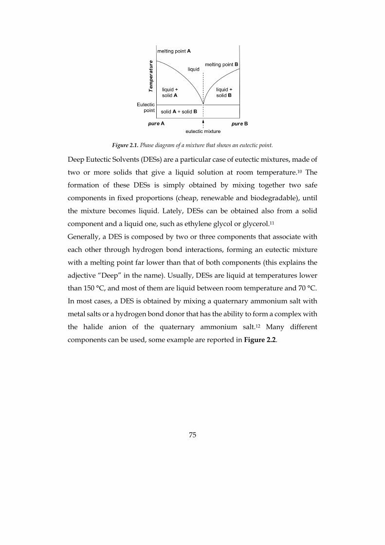
75
Figure 2.1. Phase diagram of a mixture that shows an eutectic point.
Deep Eutectic Solvents (DESs) are a particular case of eutectic mixtures, made of
two or more solids that give a liquid solution at room temperature.10 The
formation of these DESs is simply obtained by mixing together two safe
components in fixed proportions (cheap, renewable and biodegradable), until
the mixture becomes liquid. Lately, DESs can be obtained also from a solid
component and a liquid one, such as ethylene glycol or glycerol.11
Generally, a DES is composed by two or three components that associate with
each other through hydrogen bond interactions, forming an eutectic mixture
with a melting point far lower than that of both components (this explains the
adjective “Deep” in the name). Usually, DESs are liquid at temperatures lower
than 150 °C, and most of them are liquid between room temperature and 70 °C.
In most cases, a DES is obtained by mixing a quaternary ammonium salt with
metal salts or a hydrogen bond donor that has the ability to form a complex with
the halide anion of the quaternary ammonium salt.12 Many different
components can be used, some example are reported in Figure 2.2.
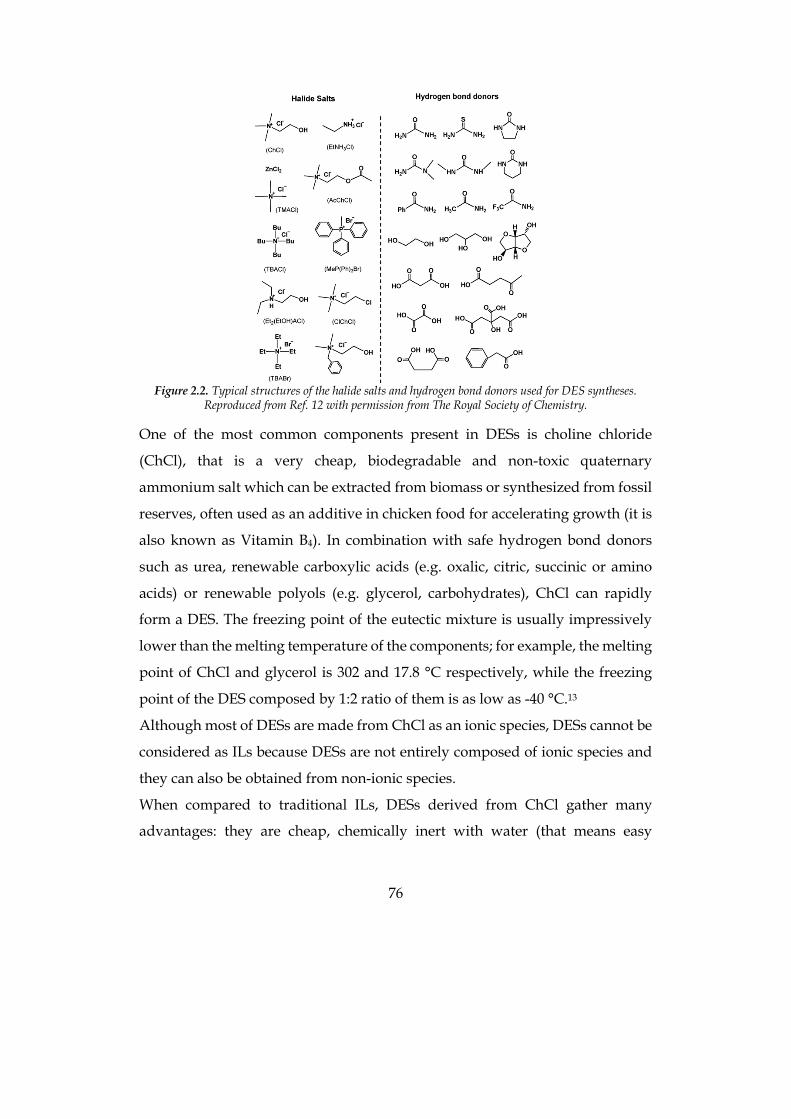
76
Figure 2.2. Typical structures of the halide salts and hydrogen bond donors used for DES syntheses.
Reproduced from Ref. 12 with permission from The Royal Society of Chemistry.
One of the most common components present in DESs is choline chloride
(ChCl), that is a very cheap, biodegradable and non-toxic quaternary
ammonium salt which can be extracted from biomass or synthesized from fossil
reserves, often used as an additive in chicken food for accelerating growth (it is
also known as Vitamin B4). In combination with safe hydrogen bond donors
such as urea, renewable carboxylic acids (e.g. oxalic, citric, succinic or amino
acids) or renewable polyols (e.g. glycerol, carbohydrates), ChCl can rapidly
form a DES. The freezing point of the eutectic mixture is usually impressively
lower than the melting temperature of the components; for example, the melting
point of ChCl and glycerol is 302 and 17.8 °C respectively, while the freezing
point of the DES composed by 1:2 ratio of them is as low as -40 °C.13
Although most of DESs are made from ChCl as an ionic species, DESs cannot be
considered as ILs because DESs are not entirely composed of ionic species and
they can also be obtained from non-ionic species.
When compared to traditional ILs, DESs derived from ChCl gather many
advantages: they are cheap, chemically inert with water (that means easy
77
storage), easy to prepare since DESs are obtained by simply mixing two
components, thus by-passing all problems of purification and waste disposal
generally encountered with ILs, and most of them are biodegradable,14
biocompatible15 and nontoxic.16
These DESs are attractive since they have physico-chemical properties similar to
traditional imidazolium-based ILs and thus can advantageously replace them in
many applications. As compared to traditional organic solvents, DESs are not
considered as volatile organic solvents and they are not flammable, making their
storage convenient. Additionally, synthesis of DESs is characterized by a 100%
atom economy, it is easy to handle and does not need any purification, thus
making their large-scale use feasible.
Since it is possible to prepare DESs made of so many different components, their
physicochemical properties can be widely tuned so that they can find many
different applications. For example, density is usually higher than water, but the
range can go from 1.04 to 1.63 g mL-1.12 Usually, DESs have a high viscosity, often
attributed to the hydrogen bond network between the components, that causes
a lower mobility of species inside the solution. At 20 °C, DESs viscosity ranges
from 19 to 85 000 cP, while water is 1 cP.12 Such high density and viscosity can
be considered an important drawback for industrial scale or in continuous-flow
applications, but adding another component such as water, a carboxylic acid or
a halide frequently solves this problem and makes DESs even more versatile.
An impressive feature of DESs is their dissolving ability; for example, a
ChCl/urea 1:2 DES can dissolve water-soluble inorganic salts (e.g. LiCl) but also
scarcely water-soluble ones (e.g. AgCl), aromatic acids such as benzoic acid and
amino acids,17 and even various metal oxides, and this could lead to a green way
for metal recycle process. 18
Thanks to all the peculiar properties of these solvents, they are applied in many
different fields, for example in extraction and separation processes,19-21 for metal
electrodeposition,10 in polymerisation and material sciences,22-23 but they have

78
recently gained increasing attention also in other hot fields of science such as
metal-,24-29 bio-,30-34 and organocatalysis,35-37 photosynthesis and
electrochemistry,38-39 and organometallics26, 40-45 with surprising and unexpected
results.
Among all of this variety of publications, also an application of DESs in DSSCs
has been reported by Jhong et al. in 2009; using a DES composed by glycerol and
choline iodide as electrolyte solvent, an efficiency of 3.88% has been obtained
under 1 sun illumination.46 To the best of our knowledge, no other examples of
DES-based DSSCs are present in the literature, apart from the ones illustrated in
this PhD work.
79
2.2 Aqueous-DES based DSSC
Among the alternative technologies for energy production free from fossil fuels,
in the last two decades research focused the attention on third generation
photovoltaics (PV), aiming to high-efficiency and low cost cells based on thin
film technology, using both organic and inorganic materials.47 The most studied
devices in this class were dye-sensitized solar cells (DSSCs), that promised to be
easy to fabricate, efficient and low cost.48-50 One of the main drawbacks of this
kind of cells is the electrolyte solution: they usually employ volatile organic
solvents (VOCs), that are often toxic, such as acetonitrile. This is a serious issue
to be afforded in order to have a widespread use of these devices. In order to
overcome these problems, different electrolytes have been proposed as
electrolyte media, such as ionic liquids (ILs),51 liquid solutions adsorbed on
polymeric matrix,49, 52-54 and even solid state cells free from any solvent.55-56 Each
of these configurations carries some disadvantages: for example, the
performance and the price of the cells are often negatively affected. Therefore,
an easy-available, sustainable, low cost electrolyte media, retaining an efficiency
comparable to VOCs, would give an important boost to a wider diffusion of
DSSCs.
In the last years, many efforts have been made to employ a perfectly eco-friendly
solvent in DSSCs: water.57 Of course, it is abundant, non-toxic and cheap, but it
is an atypical solvent for DSSCs. Usually, it was avoided because of its
detrimental effects on DSSCs performance. For example, water negatively
affects the stability of the covalent grafting of the sensitizer to the photoanode
semiconductor oxide, typically TiO2, leading to dye desorption and
corresponding shutdown of the device. Furthermore, water can negatively shift
the TiO2 conduction band, interact with additives and salts present in the
electrolyte solution, and inhibit the interfacial contact between the electrolyte
phase and the dye-coated semiconductor surface when common hydrophobic
80
sensitizers are used. 58 Nevertheless, very exhaustive works have been recently
published using water as the electrolyte solvent, but efficiencies are usually low,
ranging from less than 1% to 4%.57, 59-60
In the last years, a new category of solvents has been proposed: the Deep
Eutectic Solvents (DESs).61 As described previously, DESs show many physico-
chemical properties similar to ILs, such as density, viscosity, refractive index,
conductivity, surface tension, chemical inertness, etc., but they also have some
great advantages over ILs. In fact, DESs were studied to overcome some
drawbacks of ILs, that are often expensive, toxic and poorly biodegradable, and
their synthesis is not eco-friendly at all.
DESs are obtained by just mixing together two or three safe components that can
form an eutectic mixture, liquid at room temperature. One of the most used
component is choline chloride, also known as vitamin B4, that is a very cheap
(ca. 2 € kg-1), biodegradable and non-toxic quaternary ammonium salt, and it is
mixed with safe hydrogen bond donors such as urea, carboxylic acids (e.g.
oxalic, citric, succinic or amino acids) or polyols (e.g. glycerol, carbohydrates).
In this way a solvent is obtained that cannot be considered as ILs because DESs
are not entirely composed of ionic species and they can also be obtained from
non-ionic species. This kind of solvent is easy to prepare (it is just a mixture of
the components), cheap, low volatile, non-flammable and, last but not least, they
are biodegradable, biocompatible and non-toxic.
To the best of our knowledge, however, applications of DESs in electrochemistry
and energy conversion are still limited.62 The only example in the literature of
exploitation of a DES [namely choline iodide–glycerol (1:3, mol mol–1)] in DSSCs
has recently been reported by Wong and co-workers.46 In combination with an
organic sensitizer, these authors have reported a PCE of 3.9% vs a value of 4.9%
of a control experiment in CH3CN as the electrolyte solvent. However, in this
case, the whole electrolyte solvent was constituted by a mixture of 1-propyl-3-
methylimidazolium iodide (PMII) and the aforementioned DES (13:7, v v–1),
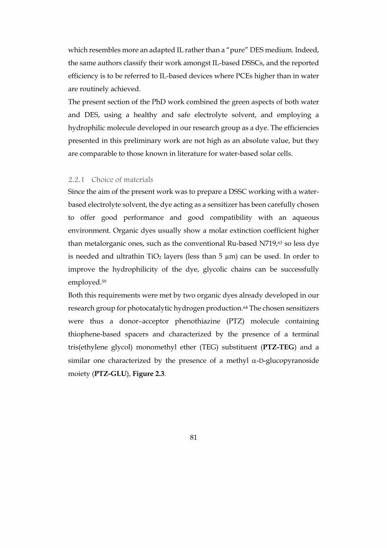
81
which resembles more an adapted IL rather than a “pure” DES medium. Indeed,
the same authors classify their work amongst IL-based DSSCs, and the reported
efficiency is to be referred to IL-based devices where PCEs higher than in water
are routinely achieved.
The present section of the PhD work combined the green aspects of both water
and DES, using a healthy and safe electrolyte solvent, and employing a
hydrophilic molecule developed in our research group as a dye. The efficiencies
presented in this preliminary work are not high as an absolute value, but they
are comparable to those known in literature for water-based solar cells.
2.2.1 Choice of materials
Since the aim of the present work was to prepare a DSSC working with a water-
based electrolyte solvent, the dye acting as a sensitizer has been carefully chosen
to offer good performance and good compatibility with an aqueous
environment. Organic dyes usually show a molar extinction coefficient higher
than metalorganic ones, such as the conventional Ru-based N719,63 so less dye
is needed and ultrathin TiO2 layers (less than 5 µm) can be used. In order to
improve the hydrophilicity of the dye, glycolic chains can be successfully
employed.59
Both this requirements were met by two organic dyes already developed in our
research group for photocatalytic hydrogen production.64 The chosen sensitizers
were thus a donor–acceptor phenothiazine (PTZ) molecule containing
thiophene-based spacers and characterized by the presence of a terminal
tris(ethylene glycol) monomethyl ether (TEG) substituent (PTZ-TEG) and a
similar one characterized by the presence of a methyl a-D-glucopyranoside
moiety (PTZ-GLU), Figure 2.3.
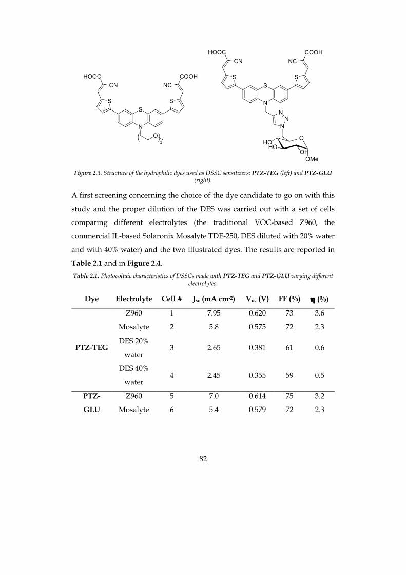
82
Figure 2.3. Structure of the hydrophilic dyes used as DSSC sensitizers: PTZ-TEG (left) and PTZ-GLU
(right).
A first screening concerning the choice of the dye candidate to go on with this
study and the proper dilution of the DES was carried out with a set of cells
comparing different electrolytes (the traditional VOC-based Z960, the
commercial IL-based Solaronix Mosalyte TDE-250, DES diluted with 20% water
and with 40% water) and the two illustrated dyes. The results are reported in
Table 2.1 and in Figure 2.4. Table 2.1. Photovoltaic characteristics of DSSCs made with PTZ-TEG and PTZ-GLU varying different
electrolytes.
Dye Electrolyte Cell # Jsc (mA cm-2) Voc (V) FF (%) h (%)
PTZ-TEG
Z960 1 7.95 0.620 73 3.6
Mosalyte 2 5.8 0.575 72 2.3
DES 20%
water 3 2.65 0.381 61 0.6
DES 40%
water 4 2.45 0.355 59 0.5
PTZ-
GLU
Z960 5 7.0 0.614 75 3.2
Mosalyte 6 5.4 0.579 72 2.3
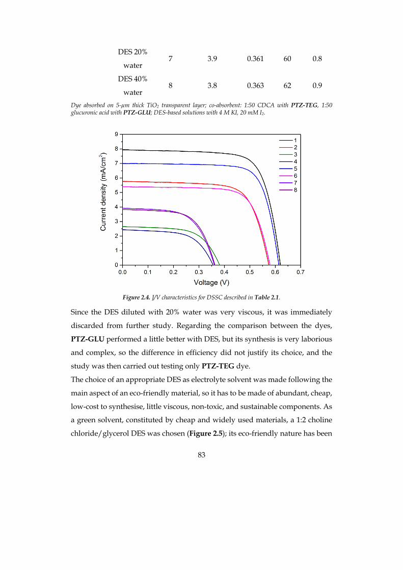
83
DES 20%
water 7 3.9 0.361 60 0.8
DES 40%
water 8 3.8 0.363 62 0.9
Dye absorbed on 5-µm thick TiO2 transparent layer; co-absorbent: 1:50 CDCA with PTZ-TEG, 1:50 glucuronic acid with PTZ-GLU; DES-based solutions with 4 M KI, 20 mM I2.
Figure 2.4. J/V characteristics for DSSC described in Table 2.1.
Since the DES diluted with 20% water was very viscous, it was immediately
discarded from further study. Regarding the comparison between the dyes,
PTZ-GLU performed a little better with DES, but its synthesis is very laborious
and complex, so the difference in efficiency did not justify its choice, and the
study was then carried out testing only PTZ-TEG dye.
The choice of an appropriate DES as electrolyte solvent was made following the
main aspect of an eco-friendly material, so it has to be made of abundant, cheap,
low-cost to synthesise, little viscous, non-toxic, and sustainable components. As
a green solvent, constituted by cheap and widely used materials, a 1:2 choline
chloride/glycerol DES was chosen (Figure 2.5); its eco-friendly nature has been
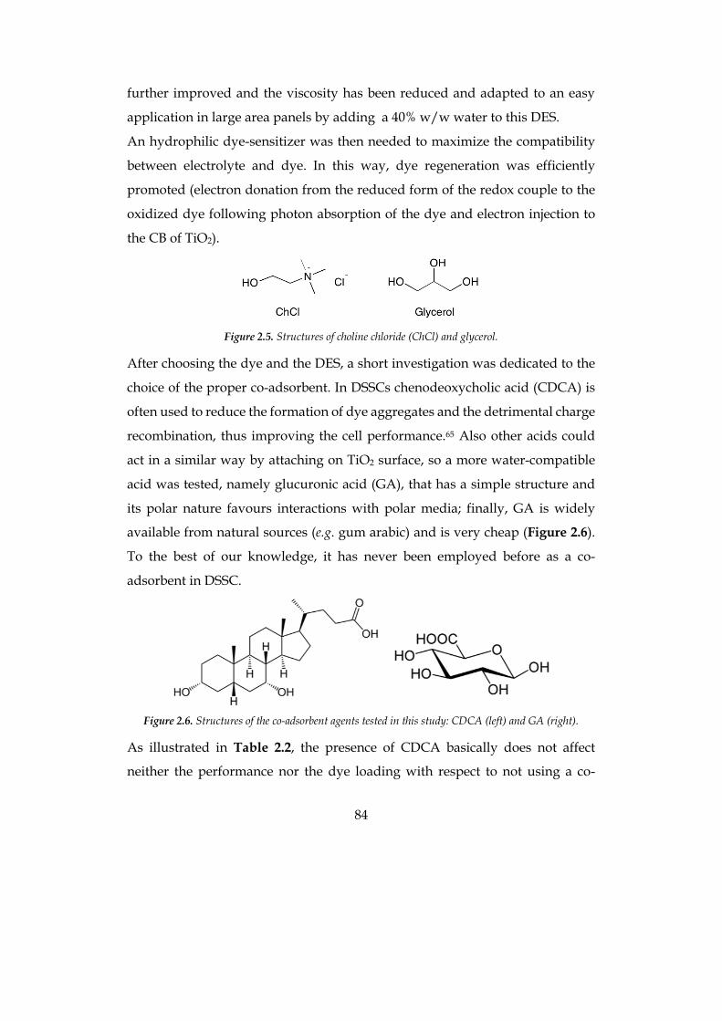
84
further improved and the viscosity has been reduced and adapted to an easy
application in large area panels by adding a 40% w/w water to this DES.
An hydrophilic dye-sensitizer was then needed to maximize the compatibility
between electrolyte and dye. In this way, dye regeneration was efficiently
promoted (electron donation from the reduced form of the redox couple to the
oxidized dye following photon absorption of the dye and electron injection to
the CB of TiO2).
Figure 2.5. Structures of choline chloride (ChCl) and glycerol.
After choosing the dye and the DES, a short investigation was dedicated to the
choice of the proper co-adsorbent. In DSSCs chenodeoxycholic acid (CDCA) is
often used to reduce the formation of dye aggregates and the detrimental charge
recombination, thus improving the cell performance.65 Also other acids could
act in a similar way by attaching on TiO2 surface, so a more water-compatible
acid was tested, namely glucuronic acid (GA), that has a simple structure and
its polar nature favours interactions with polar media; finally, GA is widely
available from natural sources (e.g. gum arabic) and is very cheap (Figure 2.6).
To the best of our knowledge, it has never been employed before as a co-
adsorbent in DSSC.
Figure 2.6. Structures of the co-adsorbent agents tested in this study: CDCA (left) and GA (right).
As illustrated in Table 2.2, the presence of CDCA basically does not affect
neither the performance nor the dye loading with respect to not using a co-
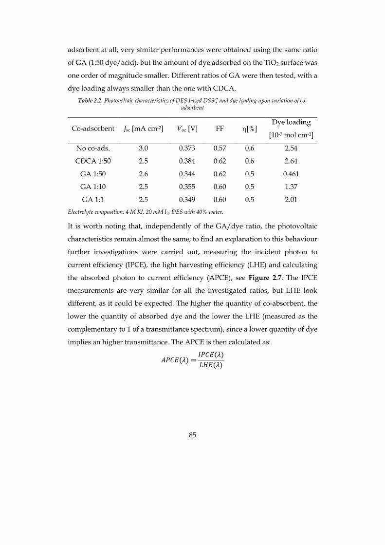
85
adsorbent at all; very similar performances were obtained using the same ratio
of GA (1:50 dye/acid), but the amount of dye adsorbed on the TiO2 surface was
one order of magnitude smaller. Different ratios of GA were then tested, with a
dye loading always smaller than the one with CDCA. Table 2.2. Photovoltaic characteristics of DES-based DSSC and dye loading upon variation of co-
adsorbent
Co-adsorbent Jsc [mA cm-2] Voc [V] FF h[%] Dye loading
[10-7 mol cm-2]
No co-ads. 3.0 0.373 0.57 0.6 2.54
CDCA 1:50 2.5 0.384 0.62 0.6 2.64
GA 1:50 2.6 0.344 0.62 0.5 0.461
GA 1:10 2.5 0.355 0.60 0.5 1.37
GA 1:1 2.5 0.349 0.60 0.5 2.01 Electrolyte composition: 4 M KI, 20 mM I2, DES with 40% water.
It is worth noting that, independently of the GA/dye ratio, the photovoltaic
characteristics remain almost the same; to find an explanation to this behaviour
further investigations were carried out, measuring the incident photon to
current efficiency (IPCE), the light harvesting efficiency (LHE) and calculating
the absorbed photon to current efficiency (APCE), see Figure 2.7. The IPCE
measurements are very similar for all the investigated ratios, but LHE look
different, as it could be expected. The higher the quantity of co-absorbent, the
lower the quantity of absorbed dye and the lower the LHE (measured as the
complementary to 1 of a transmittance spectrum), since a lower quantity of dye
implies an higher transmittance. The APCE is then calculated as:
𝐴𝑃𝐶𝐸(𝜆) =𝐼𝑃𝐶𝐸(𝜆)𝐿𝐻𝐸(𝜆)
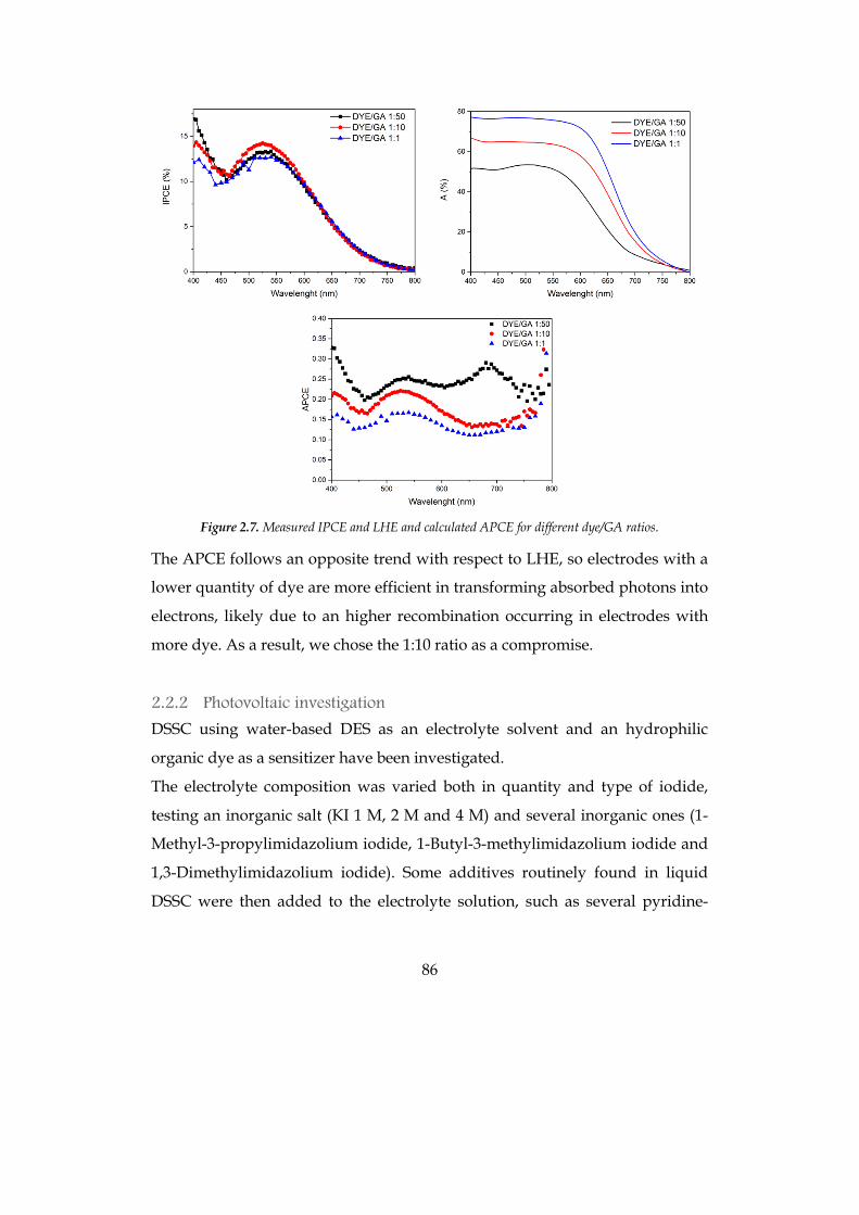
86
Figure 2.7. Measured IPCE and LHE and calculated APCE for different dye/GA ratios.
The APCE follows an opposite trend with respect to LHE, so electrodes with a
lower quantity of dye are more efficient in transforming absorbed photons into
electrons, likely due to an higher recombination occurring in electrodes with
more dye. As a result, we chose the 1:10 ratio as a compromise.
2.2.2 Photovoltaic investigation
DSSC using water-based DES as an electrolyte solvent and an hydrophilic
organic dye as a sensitizer have been investigated.
The electrolyte composition was varied both in quantity and type of iodide,
testing an inorganic salt (KI 1 M, 2 M and 4 M) and several inorganic ones (1-
Methyl-3-propylimidazolium iodide, 1-Butyl-3-methylimidazolium iodide and
1,3-Dimethylimidazolium iodide). Some additives routinely found in liquid
DSSC were then added to the electrolyte solution, such as several pyridine-
87
derivatives and guanidinium thiocyanate. To enhance TiO2 pore diffusion, thin
transparent TiO2 layers can be employed, so different transparent TiO2
thicknesses (2.5 and 5 µm) have been tested; a blocking layer and/or a scattering
layer was also investigated for a better comparison with conventional double-
layer DSSCs. Finally, two different counter electrodes were used, namely Pt and
PEDOT ones, since PEDOT counter electrodes have been reported to have better
performances in aqueous environment.59
The results of the first set investigated are summarized in Table 2.3 and the J/V
curves are illustrated in Figure 2.8. Iodine concentration was kept equal to 0.02
M in agreement with the most common values used in conventional liquid
DSSCs. At first, the cells were filled with an electrolyte based on 1 M and 2 M KI
solutions, with the 2 M cells giving a little higher current than the 1 M ones. Also
a 4 M KI solution has been tested, but it was more viscous and did not carry any
big improvement in the PV performance, so it was not considered anymore in
the study.
A significant improvement was recorded when using an ionic liquid as iodide
source; as for KI, three concentrations of 1-Methyl-3-propylimidazolium iodide
(PMII) solutions were tested, 1 M, 2 M and 4 M, with a good improvement in the
photocurrent. 4 M cells showed the best performance, with a 1.7% efficiency, but
it is worth noting that the biggest part of the solution was constituted by the
ionic liquid with just a small quantity of aqueous DES (the concentration of pure
PMII is 6 M), so DES could not be considered the solvent; thus, this result has
been discarded.
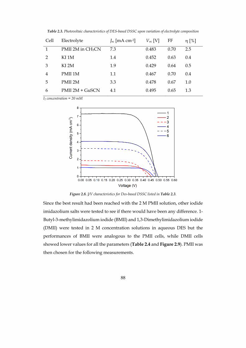
88
Table 2.3. Photovoltaic characteristics of DES-based DSSC upon variation of electrolyte composition
Cell Electrolyte Jsc [mA cm-2] Voc [V] FF h [%]
1 PMII 2M in CH3CN 7.3 0.483 0.70 2.5
2 KI 1M 1.4 0.452 0.63 0.4
3 KI 2M 1.9 0.429 0.64 0.5
4 PMII 1M 1.1 0.467 0.70 0.4
5 PMII 2M 3.3 0.478 0.67 1.0
6 PMII 2M + GuSCN 4.1 0.495 0.65 1.3
I2 concentration = 20 mM
Figure 2.8. J/V characteristics for Des-based DSSC listed in Table 2.3.
Since the best result had been reached with the 2 M PMII solution, other iodide
imidazolium salts were tested to see if there would have been any difference. 1-
Butyl-3-methylimidazolium iodide (BMII) and 1,3-Dimethylimidazolium iodide
(DMII) were tested in 2 M concentration solutions in aqueous DES but the
performances of BMII were analogous to the PMII cells, while DMII cells
showed lower values for all the parameters (Table 2.4 and Figure 2.9). PMII was
then chosen for the following measurements.
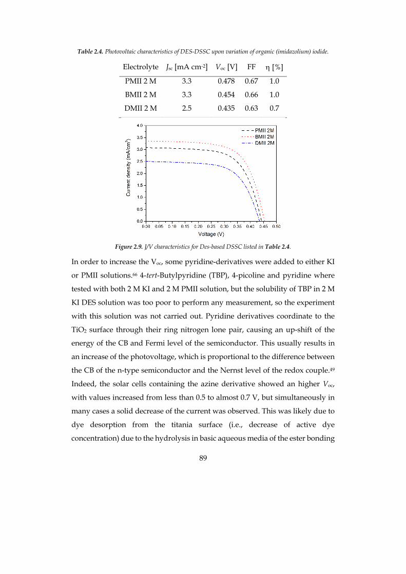
89
Table 2.4. Photovoltaic characteristics of DES-DSSC upon variation of organic (imidazolium) iodide.
Electrolyte Jsc [mA cm-2] Voc [V] FF h [%]
PMII 2 M 3.3 0.478 0.67 1.0
BMII 2 M 3.3 0.454 0.66 1.0
DMII 2 M 2.5 0.435 0.63 0.7
Figure 2.9. J/V characteristics for Des-based DSSC listed in Table 2.4.
In order to increase the Voc, some pyridine-derivatives were added to either KI
or PMII solutions.66 4-tert-Butylpyridine (TBP), 4-picoline and pyridine where
tested with both 2 M KI and 2 M PMII solution, but the solubility of TBP in 2 M
KI DES solution was too poor to perform any measurement, so the experiment
with this solution was not carried out. Pyridine derivatives coordinate to the
TiO2 surface through their ring nitrogen lone pair, causing an up-shift of the
energy of the CB and Fermi level of the semiconductor. This usually results in
an increase of the photovoltage, which is proportional to the difference between
the CB of the n-type semiconductor and the Nernst level of the redox couple.49
Indeed, the solar cells containing the azine derivative showed an higher Voc,
with values increased from less than 0.5 to almost 0.7 V, but simultaneously in
many cases a solid decrease of the current was observed. This was likely due to
dye desorption from the titania surface (i.e., decrease of active dye
concentration) due to the hydrolysis in basic aqueous media of the ester bonding
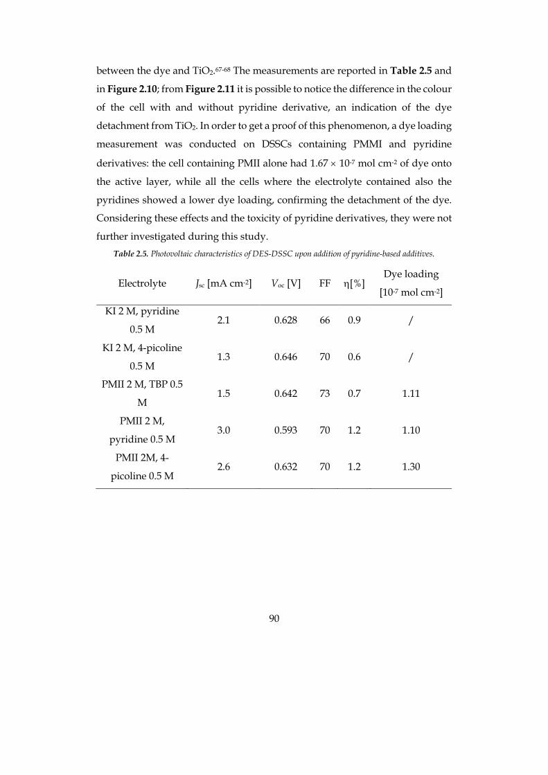
90
between the dye and TiO2.67-68 The measurements are reported in Table 2.5 and
in Figure 2.10; from Figure 2.11 it is possible to notice the difference in the colour
of the cell with and without pyridine derivative, an indication of the dye
detachment from TiO2. In order to get a proof of this phenomenon, a dye loading
measurement was conducted on DSSCs containing PMMI and pyridine
derivatives: the cell containing PMII alone had 1.67 ´ 10-7 mol cm-2 of dye onto
the active layer, while all the cells where the electrolyte contained also the
pyridines showed a lower dye loading, confirming the detachment of the dye.
Considering these effects and the toxicity of pyridine derivatives, they were not
further investigated during this study. Table 2.5. Photovoltaic characteristics of DES-DSSC upon addition of pyridine-based additives.
Electrolyte Jsc [mA cm-2] Voc [V] FF h[%] Dye loading
[10-7 mol cm-2]
KI 2 M, pyridine
0.5 M 2.1 0.628 66 0.9 /
KI 2 M, 4-picoline
0.5 M 1.3 0.646 70 0.6 /
PMII 2 M, TBP 0.5
M 1.5 0.642 73 0.7 1.11
PMII 2 M,
pyridine 0.5 M 3.0 0.593 70 1.2 1.10
PMII 2M, 4-
picoline 0.5 M 2.6 0.632 70 1.2 1.30
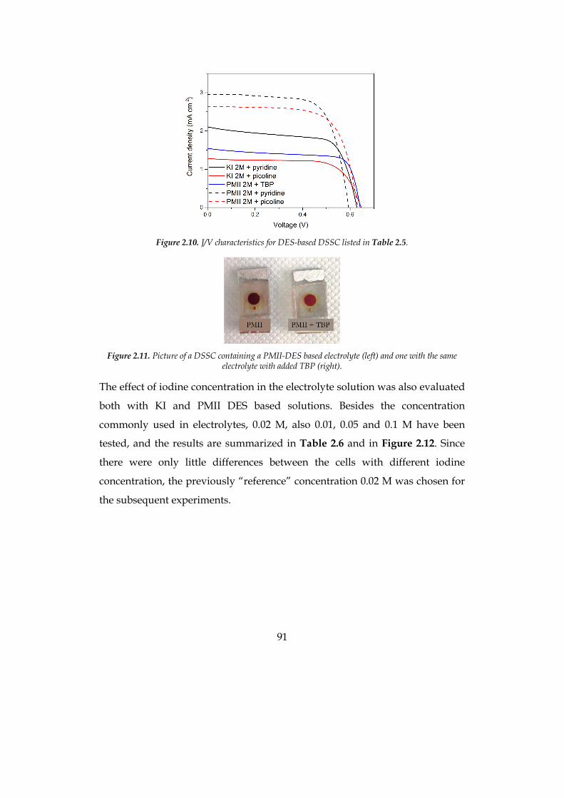
91
Figure 2.10. J/V characteristics for DES-based DSSC listed in Table 2.5.
Figure 2.11. Picture of a DSSC containing a PMII-DES based electrolyte (left) and one with the same
electrolyte with added TBP (right).
The effect of iodine concentration in the electrolyte solution was also evaluated
both with KI and PMII DES based solutions. Besides the concentration
commonly used in electrolytes, 0.02 M, also 0.01, 0.05 and 0.1 M have been
tested, and the results are summarized in Table 2.6 and in Figure 2.12. Since
there were only little differences between the cells with different iodine
concentration, the previously “reference” concentration 0.02 M was chosen for
the subsequent experiments.
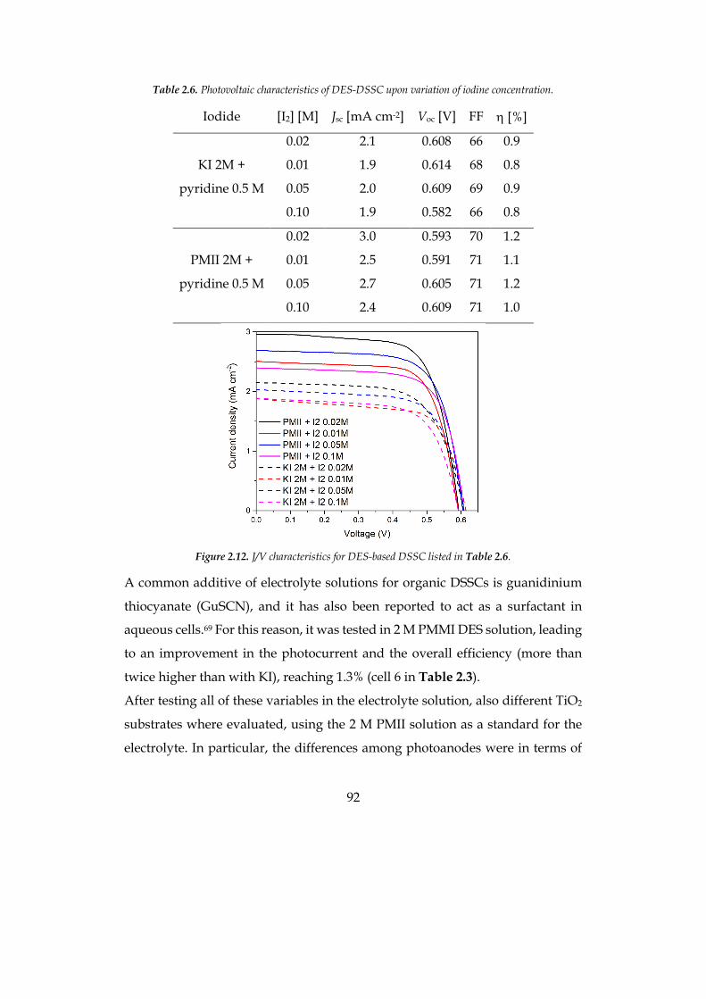
92
Table 2.6. Photovoltaic characteristics of DES-DSSC upon variation of iodine concentration.
Iodide [I2] [M] Jsc [mA cm-2] Voc [V] FF h [%]
KI 2M +
pyridine 0.5 M
0.02 2.1 0.608 66 0.9
0.01 1.9 0.614 68 0.8
0.05 2.0 0.609 69 0.9
0.10 1.9 0.582 66 0.8
PMII 2M +
pyridine 0.5 M
0.02 3.0 0.593 70 1.2
0.01 2.5 0.591 71 1.1
0.05 2.7 0.605 71 1.2
0.10 2.4 0.609 71 1.0
Figure 2.12. J/V characteristics for DES-based DSSC listed in Table 2.6.
A common additive of electrolyte solutions for organic DSSCs is guanidinium
thiocyanate (GuSCN), and it has also been reported to act as a surfactant in
aqueous cells.69 For this reason, it was tested in 2 M PMMI DES solution, leading
to an improvement in the photocurrent and the overall efficiency (more than
twice higher than with KI), reaching 1.3% (cell 6 in Table 2.3).
After testing all of these variables in the electrolyte solution, also different TiO2
substrates where evaluated, using the 2 M PMII solution as a standard for the
electrolyte. In particular, the differences among photoanodes were in terms of
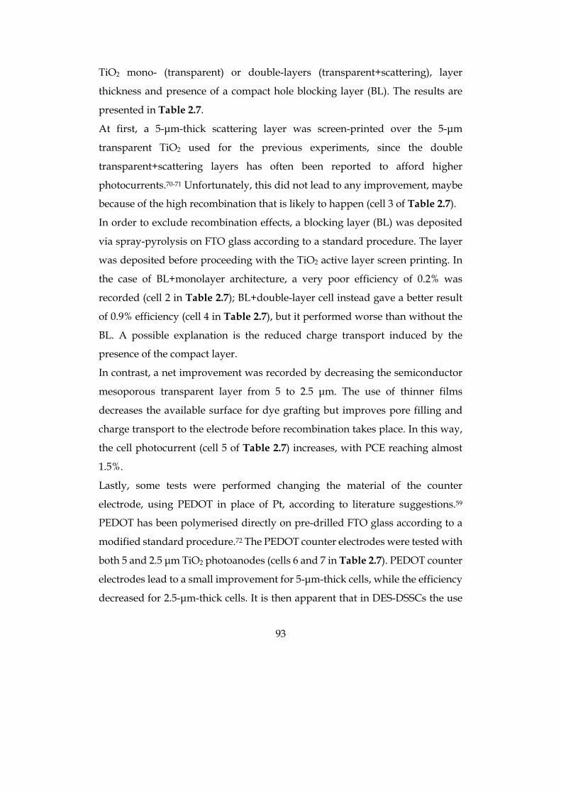
93
TiO2 mono- (transparent) or double-layers (transparent+scattering), layer
thickness and presence of a compact hole blocking layer (BL). The results are
presented in Table 2.7.
At first, a 5-µm-thick scattering layer was screen-printed over the 5-µm
transparent TiO2 used for the previous experiments, since the double
transparent+scattering layers has often been reported to afford higher
photocurrents.70-71 Unfortunately, this did not lead to any improvement, maybe
because of the high recombination that is likely to happen (cell 3 of Table 2.7).
In order to exclude recombination effects, a blocking layer (BL) was deposited
via spray-pyrolysis on FTO glass according to a standard procedure. The layer
was deposited before proceeding with the TiO2 active layer screen printing. In
the case of BL+monolayer architecture, a very poor efficiency of 0.2% was
recorded (cell 2 in Table 2.7); BL+double-layer cell instead gave a better result
of 0.9% efficiency (cell 4 in Table 2.7), but it performed worse than without the
BL. A possible explanation is the reduced charge transport induced by the
presence of the compact layer.
In contrast, a net improvement was recorded by decreasing the semiconductor
mesoporous transparent layer from 5 to 2.5 µm. The use of thinner films
decreases the available surface for dye grafting but improves pore filling and
charge transport to the electrode before recombination takes place. In this way,
the cell photocurrent (cell 5 of Table 2.7) increases, with PCE reaching almost
1.5%.
Lastly, some tests were performed changing the material of the counter
electrode, using PEDOT in place of Pt, according to literature suggestions.59
PEDOT has been polymerised directly on pre-drilled FTO glass according to a
modified standard procedure.72 The PEDOT counter electrodes were tested with
both 5 and 2.5 µm TiO2 photoanodes (cells 6 and 7 in Table 2.7). PEDOT counter
electrodes lead to a small improvement for 5-µm-thick cells, while the efficiency
decreased for 2.5-µm-thick cells. It is then apparent that in DES-DSSCs the use
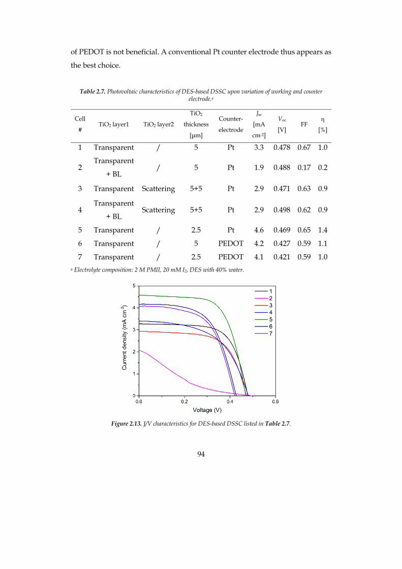
94
of PEDOT is not beneficial. A conventional Pt counter electrode thus appears as
the best choice.
Table 2.7. Photovoltaic characteristics of DES-based DSSC upon variation of working and counter
electrode.a
Cell
# TiO2 layer1 TiO2 layer2
TiO2
thickness
[µm]
Counter-
electrode
Jsc
[mA
cm-2]
Voc
[V] FF
h
[%]
1 Transparent / 5 Pt 3.3 0.478 0.67 1.0
2 Transparent
+ BL / 5 Pt 1.9 0.488 0.17 0.2
3 Transparent Scattering 5+5 Pt 2.9 0.471 0.63 0.9
4 Transparent
+ BL Scattering 5+5 Pt 2.9 0.498 0.62 0.9
5 Transparent / 2.5 Pt 4.6 0.469 0.65 1.4
6 Transparent / 5 PEDOT 4.2 0.427 0.59 1.1
7 Transparent / 2.5 PEDOT 4.1 0.421 0.59 1.0 a Electrolyte composition: 2 M PMII, 20 mM I2, DES with 40% water.
Figure 2.13. J/V characteristics for DES-based DSSC listed in Table 2.7.
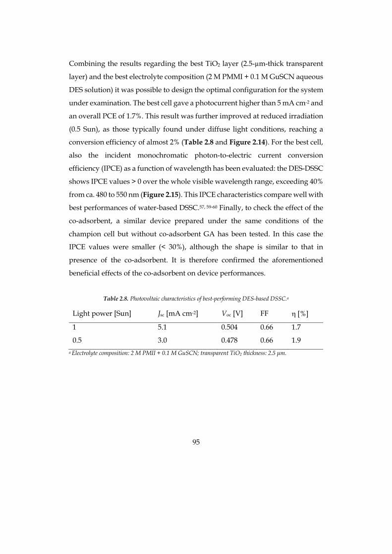
95
Combining the results regarding the best TiO2 layer (2.5-µm-thick transparent
layer) and the best electrolyte composition (2 M PMMI + 0.1 M GuSCN aqueous
DES solution) it was possible to design the optimal configuration for the system
under examination. The best cell gave a photocurrent higher than 5 mA cm-2 and
an overall PCE of 1.7%. This result was further improved at reduced irradiation
(0.5 Sun), as those typically found under diffuse light conditions, reaching a
conversion efficiency of almost 2% (Table 2.8 and Figure 2.14). For the best cell,
also the incident monochromatic photon-to-electric current conversion
efficiency (IPCE) as a function of wavelength has been evaluated: the DES-DSSC
shows IPCE values > 0 over the whole visible wavelength range, exceeding 40%
from ca. 480 to 550 nm (Figure 2.15). This IPCE characteristics compare well with
best performances of water-based DSSC.57, 59-60 Finally, to check the effect of the
co-adsorbent, a similar device prepared under the same conditions of the
champion cell but without co-adsorbent GA has been tested. In this case the
IPCE values were smaller (< 30%), although the shape is similar to that in
presence of the co-adsorbent. It is therefore confirmed the aforementioned
beneficial effects of the co-adsorbent on device performances.
Table 2.8. Photovoltaic characteristics of best-performing DES-based DSSC.a
Light power [Sun] Jsc [mA cm-2] Voc [V] FF h [%]
1 5.1 0.504 0.66 1.7
0.5 3.0 0.478 0.66 1.9 a Electrolyte composition: 2 M PMII + 0.1 M GuSCN; transparent TiO2 thickness: 2.5 µm.
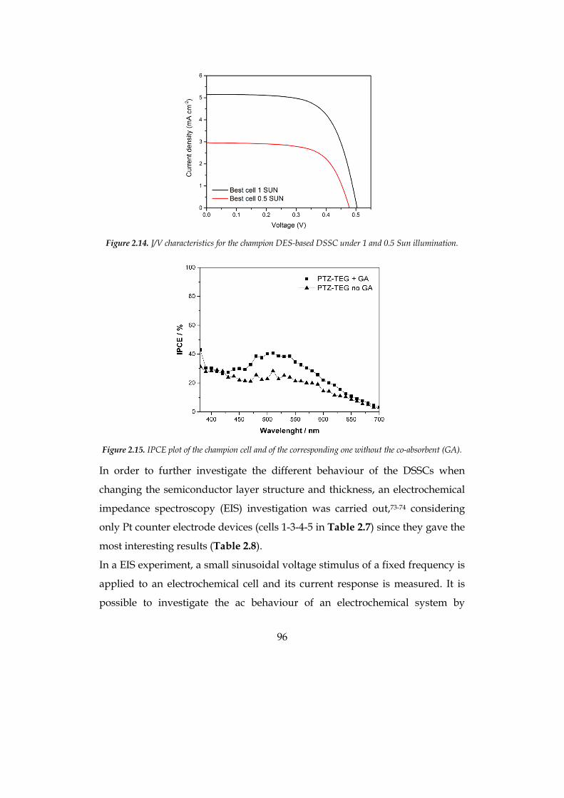
96
Figure 2.14. J/V characteristics for the champion DES-based DSSC under 1 and 0.5 Sun illumination.
Figure 2.15. IPCE plot of the champion cell and of the corresponding one without the co-absorbent (GA).
In order to further investigate the different behaviour of the DSSCs when
changing the semiconductor layer structure and thickness, an electrochemical
impedance spectroscopy (EIS) investigation was carried out,73-74 considering
only Pt counter electrode devices (cells 1-3-4-5 in Table 2.7) since they gave the
most interesting results (Table 2.8).
In a EIS experiment, a small sinusoidal voltage stimulus of a fixed frequency is
applied to an electrochemical cell and its current response is measured. It is
possible to investigate the ac behaviour of an electrochemical system by
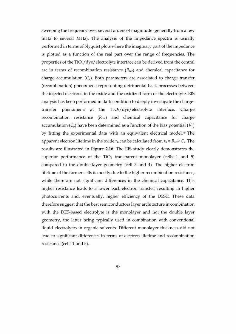
97
sweeping the frequency over several orders of magnitude (generally from a few
mHz to several MHz). The analysis of the impedance spectra is usually
performed in terms of Nyquist plots where the imaginary part of the impedance
is plotted as a function of the real part over the range of frequencies. The
properties of the TiO2/dye/electrolyte interface can be derived from the central
arc in terms of recombination resistance (Rrec) and chemical capacitance for
charge accumulation (Cµ). Both parameters are associated to charge transfer
(recombination) phenomena representing detrimental back-processes between
the injected electrons in the oxide and the oxidized form of the electrolyte. EIS
analysis has been performed in dark condition to deeply investigate the charge-
transfer phenomena at the TiO2/dye/electrolyte interface. Charge
recombination resistance (Rrec) and chemical capacitance for charge
accumulation (Cµ) have been determined as a function of the bias potential (Vb)
by fitting the experimental data with an equivalent electrical model.75 The
apparent electron lifetime in the oxide τn can be calculated from τn = Rrec×Cµ. The
results are illustrated in Figure 2.16. The EIS study clearly demonstrates the
superior performance of the TiO2 transparent monolayer (cells 1 and 5)
compared to the double-layer geometry (cell 3 and 4). The higher electron
lifetime of the former cells is mostly due to the higher recombination resistance,
while there are not significant differences in the chemical capacitance. This
higher resistance leads to a lower back-electron transfer, resulting in higher
photocurrents and, eventually, higher efficiency of the DSSC. These data
therefore suggest that the best semiconductors layer architecture in combination
with the DES-based electrolyte is the monolayer and not the double layer
geometry, the latter being typically used in combination with conventional
liquid electrolytes in organic solvents. Different monolayer thickness did not
lead to significant differences in terms of electron lifetime and recombination
resistance (cells 1 and 5).
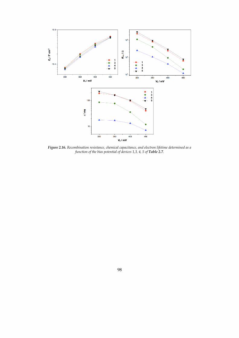
98
Figure 2.16. Recombination resistance, chemical capacitance, and electron lifetime determined as a
function of the bias potential of devices 1,3, 4, 5 of Table 2.7.
13 4 5
13 4 5
13 4 5
99
2.3 Hydrophobic-Eutectic-Solvent-based DSSC
The presence of volatile organic compounds (VOCs) as electrolyte media in dye-
sensitized solar cells (DSSCs) limits their sustainable character and prevents
widespread diffusion of this technology. This section reports, for the first time,
the use of a hydrophobic eutectic solvent (HES) as truly eco-friendly electrolyte
medium. The HES, consisting in a DL-menthol-acetic acid (1:1 molar ratio)
mixture, has been tested in DSSCs in the presence of de-aggregating agents and
a representative hydrophobic organic photosensitizer. The corresponding HES-
based devices displayed relatively good power conversion efficiencies in very
thin active layers. In particular, the highest cell photovoltage detected in
comparison to VOC-based devices may stem from a more efficient interface
interaction, as suggested by EIS studies showing the highest charge
recombination resistance and electron lifetime among all of the tested DSSCs.
2.3.1 Introduction
The increase in energy demand requires the urgent development of alternative
and renewable energy technologies.76 In particular, in order to circumvent all of
the issues deriving from the use of fossil fuels, such as climate crisis and
shortage, a promising route is to foster new photovoltaic (PV) technologies
aiming to easy-to-fabricate, efficient, and low-cost devices.77 In the last two
decades, much attention has been paid to hybrid organic-inorganic thin film
systems, such as dye- sensitized solar cells (DSSCs)49-50 and perovskite solar
cells.78 DSSCs are based on a photo-active anode, comprising an inorganic n-
type semiconductor layer (typically TiO2) sensitized by a molecular organic or
organometallic dye, a counter electrode, and a liquid electrolyte solution that
completes the circuit and allows dye regeneration. By using a liquid electrolyte,
Hanaya et al. reported a 14.7% record efficiency.79 Therefore, liquid DSSCs may
be playing an important role in the future industrial development of low-cost
solar cells with high power energy conversion efficiencies (PCEs).
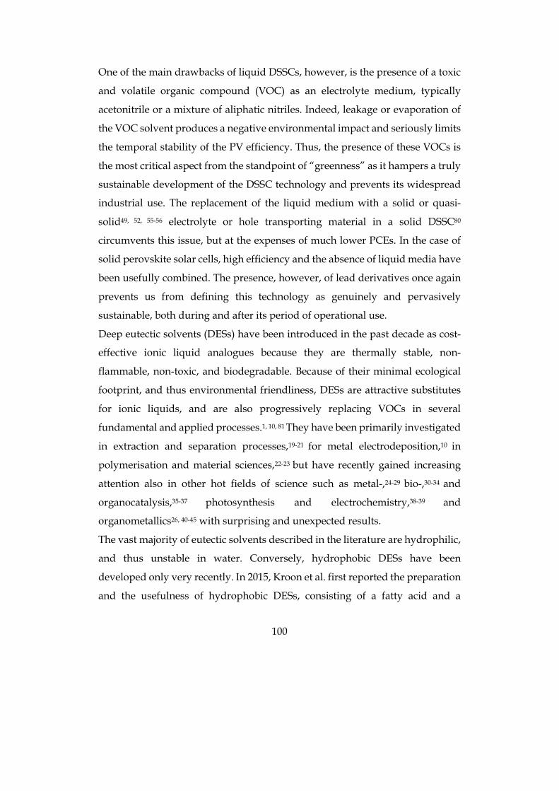
100
One of the main drawbacks of liquid DSSCs, however, is the presence of a toxic
and volatile organic compound (VOC) as an electrolyte medium, typically
acetonitrile or a mixture of aliphatic nitriles. Indeed, leakage or evaporation of
the VOC solvent produces a negative environmental impact and seriously limits
the temporal stability of the PV efficiency. Thus, the presence of these VOCs is
the most critical aspect from the standpoint of “greenness” as it hampers a truly
sustainable development of the DSSC technology and prevents its widespread
industrial use. The replacement of the liquid medium with a solid or quasi-
solid49, 52, 55-56 electrolyte or hole transporting material in a solid DSSC80
circumvents this issue, but at the expenses of much lower PCEs. In the case of
solid perovskite solar cells, high efficiency and the absence of liquid media have
been usefully combined. The presence, however, of lead derivatives once again
prevents us from defining this technology as genuinely and pervasively
sustainable, both during and after its period of operational use.
Deep eutectic solvents (DESs) have been introduced in the past decade as cost-
effective ionic liquid analogues because they are thermally stable, non-
flammable, non-toxic, and biodegradable. Because of their minimal ecological
footprint, and thus environmental friendliness, DESs are attractive substitutes
for ionic liquids, and are also progressively replacing VOCs in several
fundamental and applied processes.1, 10, 81 They have been primarily investigated
in extraction and separation processes,19-21 for metal electrodeposition,10 in
polymerisation and material sciences,22-23 but have recently gained increasing
attention also in other hot fields of science such as metal-,24-29 bio-,30-34 and
organocatalysis,35-37 photosynthesis and electrochemistry,38-39 and
organometallics26, 40-45 with surprising and unexpected results.
The vast majority of eutectic solvents described in the literature are hydrophilic,
and thus unstable in water. Conversely, hydrophobic DESs have been
developed only very recently. In 2015, Kroon et al. first reported the preparation
and the usefulness of hydrophobic DESs, consisting of a fatty acid and a
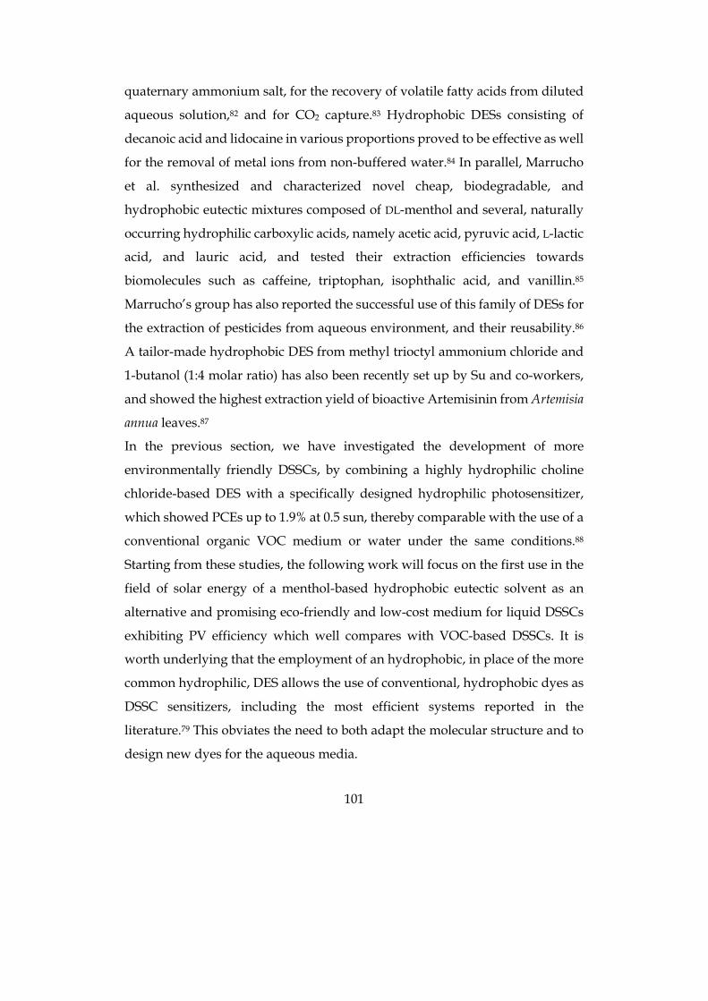
101
quaternary ammonium salt, for the recovery of volatile fatty acids from diluted
aqueous solution,82 and for CO2 capture.83 Hydrophobic DESs consisting of
decanoic acid and lidocaine in various proportions proved to be effective as well
for the removal of metal ions from non-buffered water.84 In parallel, Marrucho
et al. synthesized and characterized novel cheap, biodegradable, and
hydrophobic eutectic mixtures composed of DL-menthol and several, naturally
occurring hydrophilic carboxylic acids, namely acetic acid, pyruvic acid, L-lactic
acid, and lauric acid, and tested their extraction efficiencies towards
biomolecules such as caffeine, triptophan, isophthalic acid, and vanillin.85
Marrucho’s group has also reported the successful use of this family of DESs for
the extraction of pesticides from aqueous environment, and their reusability.86
A tailor-made hydrophobic DES from methyl trioctyl ammonium chloride and
1-butanol (1:4 molar ratio) has also been recently set up by Su and co-workers,
and showed the highest extraction yield of bioactive Artemisinin from Artemisia
annua leaves.87
In the previous section, we have investigated the development of more
environmentally friendly DSSCs, by combining a highly hydrophilic choline
chloride-based DES with a specifically designed hydrophilic photosensitizer,
which showed PCEs up to 1.9% at 0.5 sun, thereby comparable with the use of a
conventional organic VOC medium or water under the same conditions.88
Starting from these studies, the following work will focus on the first use in the
field of solar energy of a menthol-based hydrophobic eutectic solvent as an
alternative and promising eco-friendly and low-cost medium for liquid DSSCs
exhibiting PV efficiency which well compares with VOC-based DSSCs. It is
worth underlying that the employment of an hydrophobic, in place of the more
common hydrophilic, DES allows the use of conventional, hydrophobic dyes as
DSSC sensitizers, including the most efficient systems reported in the
literature.79 This obviates the need to both adapt the molecular structure and to
design new dyes for the aqueous media.
102
2.3.2 Choice of materials
We have selected as a representative sensitizer a phenotiazine-based
hydrophobic dye containing a terminal 8-carbon atom alkyl chain (PTZ-Th,
Figure 2.17) that has been previously employed both in DSSCs89 and in the
photocatalytic production of hydrogen.90 The DL-menthol-acetic acid (1:1 molar
ratio) eutectic mixture has been selected as a representative HES because it
displays very low viscosity compared to the other menthol-based eutectic
mixtures developed (Figure 2.18).85
Figure 2.17. Structure of molecule PTZ-Th.
Figure 2.18. Structure of HES components: DL-menthol (left) and acetic acid (right).
DSSC cells have been prepared using PTZ-Th as a sensitizer in the presence of
chenodeoxycholic acid (CDCA) as a disaggregating co-adsorbent.65 Different
types of TiO2 layers have been investigated including transparent and opaque
active layers with different thicknesses to find the best operative conditions. The
electrolyte medium is a DL-menthol-acetic acid (1:1) eutectic mixture, which has
been further diluted with 10% v/v EtOH (one of the recommended eco-friendly
solvents) to improve solubility of the electrolyte components and to reduce the
103
viscosity of the solution. The EtOH addition simplifies device preparation
without altering the nature of the HES, as confirmed by FT-IR spectra performed
both on pure and diluted HES (Figure 2.19). As shown by Marrucho and co-
workers, the formation of a network of hydrogen bonds between the carboxylic
acid group (hydrogen bond donor) and the alcoholic group in DL-menthol
(hydrogen bond acceptor), and thus of a eutectic mixture, is testified by a shift
towards higher wavenumbers values of the carbonyl stretching absorption
band.85 Recently, Edler has also reported that DES nanostructure is retained up
to 42 wt% water dilution. Further dilution produces an aqueous solution of DES
components.91 The perfect overlap of FT-IR spectra before and after ETOH
dilution of the eutectic mixture is consistent with the solvophobic sequestration
of EtOH into the eutectic mixture hydrogen bond network.
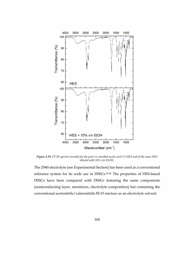
104
Figure 2.19. FT-IR spectra recorded for the pure DL-menthol-acetic acid 1:1 HES and of the same HES
diluted with 10% v/v EtOH.
The Z960 electrolyte (see Experimental Section) has been used as a conventional
reference system for its wide use in DSSCs.92-96 The properties of HES-based
DSSCs have been compared with DSSCs featuring the same components
(semiconducting layer, sensitizers, electrolyte composition) but containing the
conventional acetonitrile/valeronitrile 85:15 mixture as an electrolyte solvent.
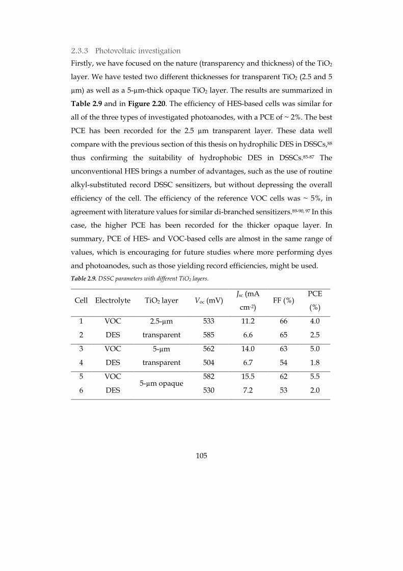
105
2.3.3 Photovoltaic investigation
Firstly, we have focused on the nature (transparency and thickness) of the TiO2
layer. We have tested two different thicknesses for transparent TiO2 (2.5 and 5
µm) as well as a 5-µm-thick opaque TiO2 layer. The results are summarized in
Table 2.9 and in Figure 2.20. The efficiency of HES-based cells was similar for
all of the three types of investigated photoanodes, with a PCE of ~ 2%. The best
PCE has been recorded for the 2.5 µm transparent layer. These data well
compare with the previous section of this thesis on hydrophilic DES in DSSCs,88
thus confirming the suitability of hydrophobic DES in DSSCs.85-87 The
unconventional HES brings a number of advantages, such as the use of routine
alkyl-substituted record DSSC sensitizers, but without depressing the overall
efficiency of the cell. The efficiency of the reference VOC cells was ~ 5%, in
agreement with literature values for similar di-branched sensitizers.89-90, 97 In this
case, the higher PCE has been recorded for the thicker opaque layer. In
summary, PCE of HES- and VOC-based cells are almost in the same range of
values, which is encouraging for future studies where more performing dyes
and photoanodes, such as those yielding record efficiencies, might be used. Table 2.9. DSSC parameters with different TiO2 layers.
Cell Electrolyte TiO2 layer Voc (mV) Jsc (mA
cm-2) FF (%)
PCE
(%)
1 VOC 2.5-µm
transparent
533 11.2 66 4.0
2 DES 585 6.6 65 2.5
3 VOC 5-µm
transparent
562 14.0 63 5.0
4 DES 504 6.7 54 1.8
5 VOC 5-µm opaque
582 15.5 62 5.5
6 DES 530 7.2 53 2.0
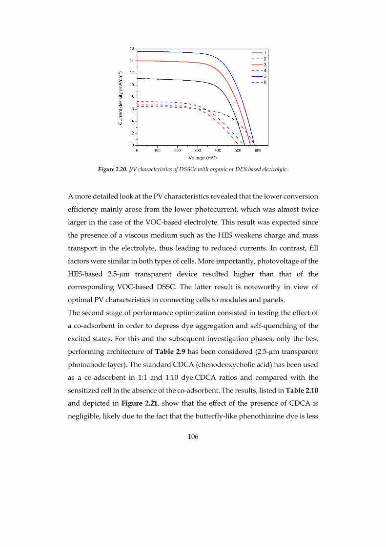
106
Figure 2.20. J/V characteristics of DSSCs with organic or DES based electrolyte.
A more detailed look at the PV characteristics revealed that the lower conversion
efficiency mainly arose from the lower photocurrent, which was almost twice
larger in the case of the VOC-based electrolyte. This result was expected since
the presence of a viscous medium such as the HES weakens charge and mass
transport in the electrolyte, thus leading to reduced currents. In contrast, fill
factors were similar in both types of cells. More importantly, photovoltage of the
HES-based 2.5-µm transparent device resulted higher than that of the
corresponding VOC-based DSSC. The latter result is noteworthy in view of
optimal PV characteristics in connecting cells to modules and panels.
The second stage of performance optimization consisted in testing the effect of
a co-adsorbent in order to depress dye aggregation and self-quenching of the
excited states. For this and the subsequent investigation phases, only the best
performing architecture of Table 2.9 has been considered (2.5-µm transparent
photoanode layer). The standard CDCA (chenodeoxycholic acid) has been used
as a co-adsorbent in 1:1 and 1:10 dye:CDCA ratios and compared with the
sensitized cell in the absence of the co-adsorbent. The results, listed in Table 2.10
and depicted in Figure 2.21, show that the effect of the presence of CDCA is
negligible, likely due to the fact that the butterfly-like phenothiazine dye is less
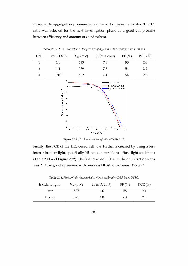
107
subjected to aggregation phenomena compared to planar molecules. The 1:1
ratio was selected for the next investigation phase as a good compromise
between efficiency and amount of co-adsorbent.
Table 2.10. DSSC parameters in the presence of different CDCA relative concentrations
Cell Dye:CDCA Voc (mV) Jsc (mA cm-2) FF (%) PCE (%)
1 1:0 533 7.0 55 2.0
2 1:1 539 7.7 54 2.2
3 1:10 562 7.4 54 2.2
Figure 2.21. J/V characteristics of cells of Table 2.10.
Finally, the PCE of the HES-based cell was further increased by using a less
intense incident light, specifically 0.5 sun, comparable to diffuse light conditions
(Table 2.11 and Figure 2.22). The final reached PCE after the optimization steps
was 2.5%, in good agreement with previous DESs88 or aqueous DSSCs.57
Table 2.11. Photovoltaic characteristics of best-performing DES-based DSSC.
Incident light Voc (mV) Jsc (mA cm-2) FF (%) PCE (%)
1 sun 537 6.6 58 2.1
0.5 sun 521 4.0 60 2.5
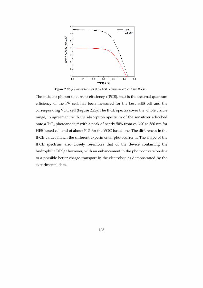
108
Figure 2.22. J/V characteristics of the best performing cell at 1 and 0.5 sun.
The incident photon to current efficiency (IPCE), that is the external quantum
efficiency of the PV cell, has been measured for the best HES cell and the
corresponding VOC cell (Figure 2.23). The IPCE spectra cover the whole visible
range, in agreement with the absorption spectrum of the sensitizer adsorbed
onto a TiO2 photoanode,98 with a peak of nearly 50% from ca. 490 to 560 nm for
HES-based cell and of about 70% for the VOC-based one. The differences in the
IPCE values match the different experimental photocurrents. The shape of the
IPCE spectrum also closely resembles that of the device containing the
hydrophilic DES,88 however, with an enhancement in the photoconversion due
to a possible better charge transport in the electrolyte as demonstrated by the
experimental data.
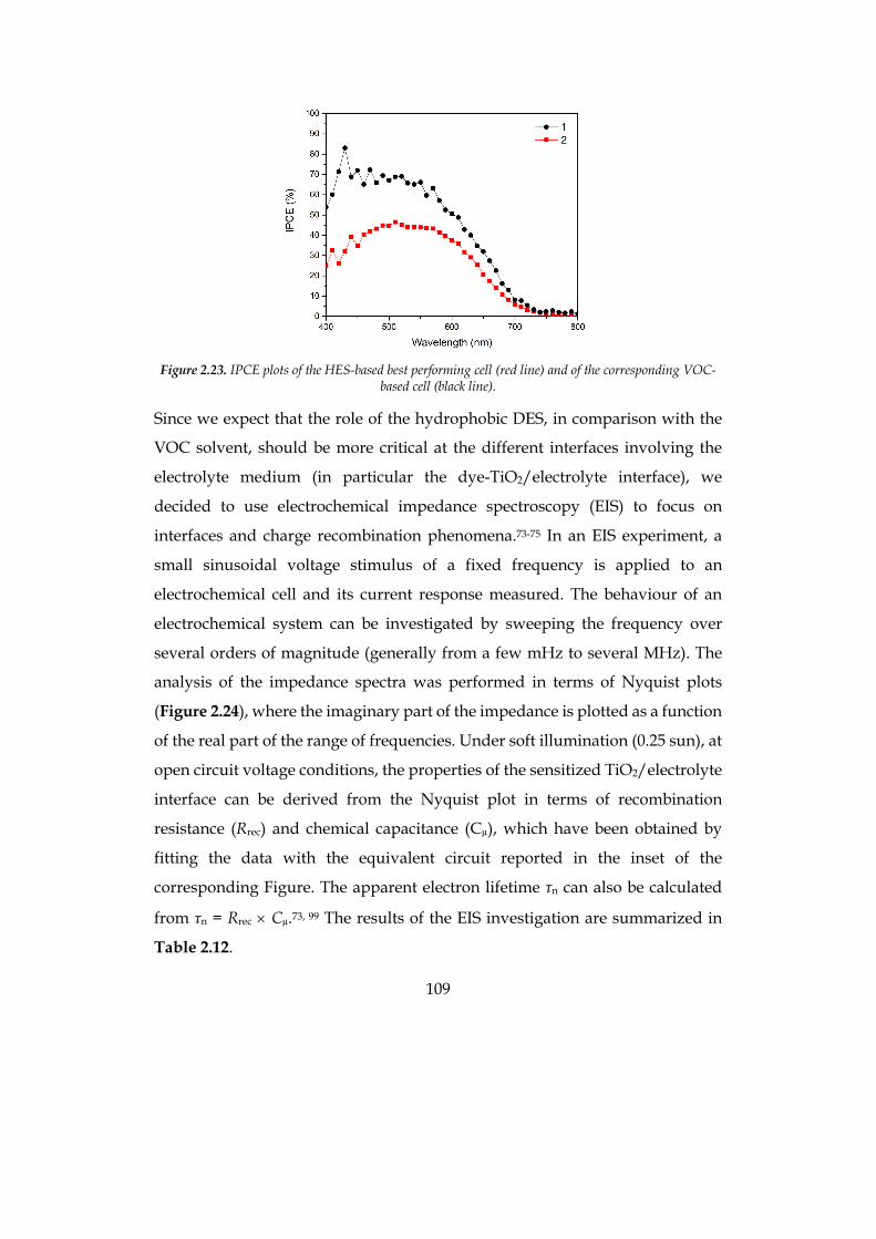
109
Figure 2.23. IPCE plots of the HES-based best performing cell (red line) and of the corresponding VOC-
based cell (black line).
Since we expect that the role of the hydrophobic DES, in comparison with the
VOC solvent, should be more critical at the different interfaces involving the
electrolyte medium (in particular the dye-TiO2/electrolyte interface), we
decided to use electrochemical impedance spectroscopy (EIS) to focus on
interfaces and charge recombination phenomena.73-75 In an EIS experiment, a
small sinusoidal voltage stimulus of a fixed frequency is applied to an
electrochemical cell and its current response measured. The behaviour of an
electrochemical system can be investigated by sweeping the frequency over
several orders of magnitude (generally from a few mHz to several MHz). The
analysis of the impedance spectra was performed in terms of Nyquist plots
(Figure 2.24), where the imaginary part of the impedance is plotted as a function
of the real part of the range of frequencies. Under soft illumination (0.25 sun), at
open circuit voltage conditions, the properties of the sensitized TiO2/electrolyte
interface can be derived from the Nyquist plot in terms of recombination
resistance (Rrec) and chemical capacitance (Cµ), which have been obtained by
fitting the data with the equivalent circuit reported in the inset of the
corresponding Figure. The apparent electron lifetime τn can also be calculated
from τn = Rrec ´ Cµ.73, 99 The results of the EIS investigation are summarized in
Table 2.12.
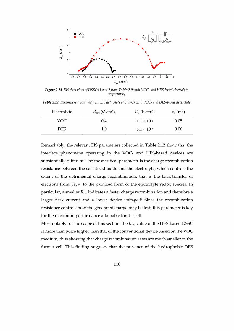
110
Figure 2.24. EIS data plots of DSSCs 1 and 2 from Table 2.9 with VOC- and HES-based electrolyte,
respectively.
Table 2.12. Parameters calculated from EIS data plots of DSSCs with VOC- and DES-based electrolyte.
Electrolyte Rrec (Ω cm2) Cµ (F cm-2) τn (ms)
VOC 0.4 1.1 ´ 10-4 0.05
DES 1.0 6.1 ´ 10-5 0.06
Remarkably, the relevant EIS parameters collected in Table 2.12 show that the
interface phenomena operating in the VOC- and HES-based devices are
substantially different. The most critical parameter is the charge recombination
resistance between the sensitized oxide and the electrolyte, which controls the
extent of the detrimental charge recombination, that is the back-transfer of
electrons from TiO2 to the oxidized form of the electrolyte redox species. In
particular, a smaller Rrec indicates a faster charge recombination and therefore a
larger dark current and a lower device voltage.49 Since the recombination
resistance controls how the generated charge may be lost, this parameter is key
for the maximum performance attainable for the cell.
Most notably for the scope of this section, the Rrec value of the HES-based DSSC
is more than twice higher than that of the conventional device based on the VOC
medium, thus showing that charge recombination rates are much smaller in the
former cell. This finding suggests that the presence of the hydrophobic DES

111
solvent in place of the conventional organic medium positively affects the
critical dye-TiO2/electrolyte interface, thereby minimizing unwanted pathways
and possibly improving performances. Accordingly, the cell photovoltage of the
HES-based cell is significantly higher (Table 2), improving from 0.53 V in the
VOC electrolyte to almost 0.6 V. Accordingly, the electron lifetime of the HES-
based cell resulted higher than that of the VOC-device though in this case
differences are smaller due to the higher chemical capacitance of the latter.
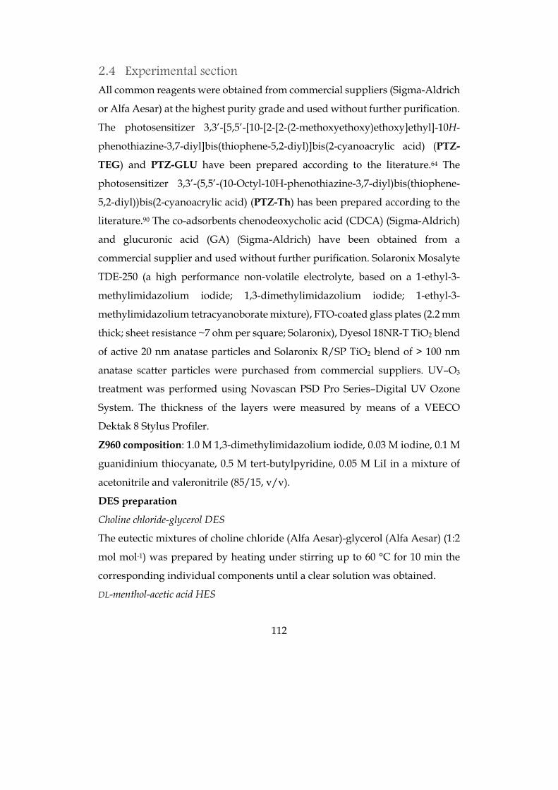
112
2.4 Experimental section All common reagents were obtained from commercial suppliers (Sigma-Aldrich
or Alfa Aesar) at the highest purity grade and used without further purification.
The photosensitizer 3,3’-[5,5’-[10-[2-[2-(2-methoxyethoxy)ethoxy]ethyl]-10H-
phenothiazine-3,7-diyl]bis(thiophene-5,2-diyl)]bis(2-cyanoacrylic acid) (PTZ-
TEG) and PTZ-GLU have been prepared according to the literature.64 The
photosensitizer 3,3’-(5,5’-(10-Octyl-10H-phenothiazine-3,7-diyl)bis(thiophene-
5,2-diyl))bis(2-cyanoacrylic acid) (PTZ-Th) has been prepared according to the
literature.90 The co-adsorbents chenodeoxycholic acid (CDCA) (Sigma-Aldrich)
and glucuronic acid (GA) (Sigma-Aldrich) have been obtained from a
commercial supplier and used without further purification. Solaronix Mosalyte
TDE-250 (a high performance non-volatile electrolyte, based on a 1-ethyl-3-
methylimidazolium iodide; 1,3-dimethylimidazolium iodide; 1-ethyl-3-
methylimidazolium tetracyanoborate mixture), FTO-coated glass plates (2.2 mm
thick; sheet resistance ~7 ohm per square; Solaronix), Dyesol 18NR-T TiO2 blend
of active 20 nm anatase particles and Solaronix R/SP TiO2 blend of > 100 nm
anatase scatter particles were purchased from commercial suppliers. UV–O3
treatment was performed using Novascan PSD Pro Series–Digital UV Ozone
System. The thickness of the layers were measured by means of a VEECO
Dektak 8 Stylus Profiler.
Z960 composition: 1.0 M 1,3-dimethylimidazolium iodide, 0.03 M iodine, 0.1 M
guanidinium thiocyanate, 0.5 M tert-butylpyridine, 0.05 M LiI in a mixture of
acetonitrile and valeronitrile (85/15, v/v).
DES preparation
Choline chloride-glycerol DES
The eutectic mixtures of choline chloride (Alfa Aesar)-glycerol (Alfa Aesar) (1:2
mol mol-1) was prepared by heating under stirring up to 60 °C for 10 min the
corresponding individual components until a clear solution was obtained.
DL-menthol-acetic acid HES
113
The employed DL-menthol-based eutectic mixture was prepared by adding
acetic acid (the hydrogen bond donor) to DL-menthol in a 1:1 molar ratio. The
corresponding mixture of the two compounds was then heated up to 50 °C until
a clear solution was obtained (15 min), and then cooled down slowly to room
temperature. Then, it was diluted with 10% v/v EtOH.
DES-DSSC preparation
DSSCs have been prepared adapting a procedure reported in the literature.100 In
order to exclude metal contamination, all of the containers were in glass or
Teflon and were treated with EtOH and 10% HCl prior to use. Plastic spatulas
and tweezers have been used throughout the procedure. FTO glass plates were
cleaned in a detergent solution for 15 min using an ultrasonic bath, rinsed with
pure water and EtOH. After treatment in a UV-O3 system for 18 min, the FTO
plates were treated with a freshly prepared 40 mM aqueous solution of TiCl4 for
30 min at 70 °C and then rinsed with water and EtOH.
In the case of the cells with blocking layer, the treatment with TiCl4 is replaced
by a spray pyrolysis deposition of a solution of 20 mM titanium diisopropoxide
bis(acetylacetonate) (Sigma-Aldrich) in anhydrous isopropanol at 450 °C for 30
min and then allowed to cool down to room temperature.
A transparent layer of 0.20 cm2 was screen-printed using a 20-nm transparent
TiO2 paste (Dyesol 18NR-T). The coated transparent film was dried at 125 °C for
5 min and when needed another layer was screen-printed by using a light
scattering TiO2 paste with particles >100 nm (Solaronix R/SP). The coated films
were thermally treated at 125 °C for 5 min, 325 °C for 10 min, 450 °C for 15 min,
and 500 °C for 15 min. The heating ramp rate was 5-10 °C/ min. The sintered
layer was treated again with 40 mM aqueous TiCl4 (70 °C for 30 min), rinsed
with EtOH and heated at 500 °C for 30 min. After cooling down to 80 °C, the
TiO2 coated plate was immersed into a 0.2 mM solution of the dye in the
presence of the co-adsorbent (typically 1:10 glucuronic acid) for 20 h at room
temperature in the dark.
114
Platinum-based counter electrodes were prepared according to the following
procedure: a 1-mm hole was made in a FTO plate, using diamond drill bits. The
electrodes were then cleaned with a detergent solution for 15 min using an
ultrasonic bath, 10% HCl, and finally acetone for 15 min using an ultrasonic bath.
Then, a 10 µL of a 5 × 10⁻³ M solution of H2PtCl6 in EtOH was added and the
electrodes were thermally treated at 500 °C for 30 min.
PEDOT-based counter electrodes were prepared adapting a literature
procedure.72 Electropolymerization of EDOT (Sigma-Aldrich) was performed
with an Autolab Potentiostat/galvanostat PGStat302N in the galvanostatic
mode; a two-electrode cell with a 2 cm × 3.75 cm FTO glass as counter electrode
and a predrilled washed 2 cm × 3.75 cm FTO glass as working electrode was
used and a constant current of 0.602 A was applied for 400 s (film thickness
about 560 nm, measured by profilometry).
The dye sensitized TiO2 electrode and the counter electrode were assembled into
a sealed sandwich-type cell by heating with a hot-melt ionomer-class resin
(Surlyn 30-µm thickness) as a spacer between the electrodes.
The electrolyte solution was prepared by mixing at room temperature iodine, KI
or PMII, and if necessary additives (i.e. GuSCN, 4-picoline, 4-tert-Butylpyridine,
or pyridine) in the proper eutectic solvent (40% aqueous diluted DES or EtOH
diluted HES) and kept in dark in the air. The electrolyte solution is used within
one week from preparation. A drop of the electrolyte solution was added to the
hole and introduced inside the cell by vacuum backfilling. Finally, the hole was
sealed with a sheet of Surlyn and a cover glass. A reflective foil at the back side
of the counter electrode was taped to reflect unabsorbed light back to the
photoanode.
DES-DSSC measurements
Photovoltaic measurements of DSSCs were carried out using a 500 W xenon
light source (ABET Technologies Sun 2000 Solar Simulator). The power of the
simulated light was calibrated to AM 1.5 (100 mW cm−2) using a reference Si
115
photodiode. Values were recorded immediately after cells assembling. I–V
curves were obtained by applying an external bias to the cell and measuring the
generated photocurrent with a Keithley model 2400 digital source meter.
Incident photon-to-current conversion efficiencies (IPCEs) were recorded as a
function of excitation wavelength (between 300–800 nm), using a
monochromator (HORIBA Jobin Yvon) and a 400 W xenon lamp as incident
light, in AC mode. The monochromatic light was mechanically chopped
(chopping frequency of 1 Hz) and the AC-photocurrent response was measured
using a lockin-amplifier. A white light bias (0.3 sun) was applied to the sample
during IPCE measurements.
Dye loading
The amount of adsorbed dye has been measured for each sample by desorbing
the dye, after the photovoltaic investigation on the dye-coated films, using a 0.1
M solution of NaOH in EtOH–H2O (1:1) and by measuring its UV-Vis spectrum
in a known volume of the solution. Comparison with the spectra of freshly
prepared solutions of the dye in the same solvent, at known concentrations, are
used to determine the amounts of desorbed dye.
Electrochemical impedance spectroscopy
Electrochemical Impedance Spectroscopy (EIS) spectra were obtained using an
Eg&G PARSTAT 2263 galvanostat-potentiostat. Measurements were performed
in the 100 kH 0.1 Hz frequency range using an AC stimulus of 70 mV under dark
conditions and with different applied voltages including open circuit
conditions.
116
2.5 Bibliography
1. Alonso, D. A.; Baeza, A.; Chinchilla, R.; Guillena, G.; Pastor, I. M.; Ramon, D. J., ”Deep Eutectic Solvents: The Organic Reaction Medium of the Century”. Eur. J. Org. Chem. 2016, 612-632, doi: 10.1002/ejoc.201501197
2. Constable, D. J. C.; Jimenez-Gonzalez, C.; Henderson, R. K., ”Perspective on Solvent Use in the Pharmaceutical Industry”. Organic Process Research & Development 2007, 11, 133-137, doi: 10.1021/op060170h
3. Shuklov, I. A.; Dubrovina, N. V.; Börner, A., ”Fluorinated Alcohols as Solvents, Cosolvents and Additives in Homogeneous Catalysis”. Synthesis 2007, 2007, 2925-2943, doi: 10.1055/s-2007-983902
4. Aparicio, S.; Alcalde, R., ”The green solvent ethyl lactate: an experimental and theoretical characterization”. Green Chem. 2009, 11, 65-78, doi: 10.1039/B811909K
5. Gu, Y.; Jérôme, F., ”Glycerol as a sustainable solvent for green chemistry”. Green Chem. 2010, 12, 1127-1138, doi: 10.1039/C001628D
6. Pace, V.; Hoyos, P.; Castoldi, L.; Domínguez de María, P.; Alcántara, A. R., ”2-Methyltetrahydrofuran (2-MeTHF): A Biomass-Derived Solvent with Broad Application in Organic Chemistry”. ChemSusChem 2012, 5, 1369-1379, doi: 10.1002/cssc.201100780
7. Earle, M. J.; Katdare, S. P.; Seddon, K. R., ”Paradigm Confirmed: The First Use of Ionic Liquids to Dramatically Influence the Outcome of Chemical Reactions”. Organic Letters 2004, 6, 707-710, doi: 10.1021/ol036310e
8. Romero, A.; Santos, A.; Tojo, J.; Rodríguez, A., ”Toxicity and biodegradability of imidazolium ionic liquids”. J. Hazard. Mater. 2008, 151, 268-273, doi: https://doi.org/10.1016/j.jhazmat.2007.10.079
9. Plechkova, N. V.; Seddon, K. R., ”Applications of ionic liquids in the chemical industry”. Chem. Soc. Rev. 2008, 37, 123-150, doi: 10.1039/B006677J
117
10. Smith, E. L.; Abbott, A. P.; Ryder, K. S., ”Deep Eutectic Solvents (DESs) and Their Applications”. Chem. Rev. 2014, 114, 11060-11082, doi: 10.1021/cr300162p
11. Abbott, A. P.; El Ttaib, K.; Frisch, G.; McKenzie, K. J.; Ryder, K. S., ”Electrodeposition of copper composites from deep eutectic solvents based on choline chloride”. Phys. Chem. Chem. Phys. 2009, 11, 4269-4277, doi: 10.1039/B817881J
12. Zhang, Q.; De Oliveira Vigier, K.; Royer, S.; Jerome, F., ”Deep eutectic solvents: syntheses, properties and applications”. Chem. Soc. Rev. 2012, 41, 7108-7146, doi: 10.1039/C2CS35178A
13. Abbott, A. P.; Harris, R. C.; Ryder, K. S.; D'Agostino, C.; Gladden, L. F.; Mantle, M. D., ”Glycerol eutectics as sustainable solvent systems”. Green Chem. 2011, 13, 82-90, doi: 10.1039/C0GC00395F
14. Yu, Y.; Lu, X.; Zhou, Q.; Dong, K.; Yao, H.; Zhang, S., ”Biodegradable Naphthenic Acid Ionic Liquids: Synthesis, Characterization, and Quantitative Structure–Biodegradation Relationship”. Chem. Eur. J. 2008, 14, 11174-11182, doi: 10.1002/chem.200800620
15. Weaver, K. D.; Kim, H. J.; Sun, J.; MacFarlane, D. R.; Elliott, G. D., ”Cyto-toxicity and biocompatibility of a family of choline phosphate ionic liquids designed for pharmaceutical applications”. Green Chem. 2010, 12, 507-513, doi: 10.1039/B918726J
16. Ilgen, F.; Ott, D.; Kralisch, D.; Reil, C.; Palmberger, A.; König, B., ”Conversion of carbohydrates into 5-hydroxymethylfurfural in highly concentrated low melting mixtures”. Green Chem. 2009, 11, 1948-1954, doi: 10.1039/B917548M
17. Abbott, A. P.; Capper, G.; Davies, D. L.; Rasheed, R. K.; Tambyrajah, V., ”Novel solvent properties of choline chloride/urea mixtures”. Chem. Commun. 2003, 70-71, doi: 10.1039/B210714G
18. Abbott, A. P.; Boothby, D.; Capper, G.; Davies, D. L.; Rasheed, R. K., ”Deep Eutectic Solvents Formed between Choline Chloride and Carboxylic Acids: Versatile Alternatives to Ionic Liquids”. J. Am. Chem. Soc. 2004, 126, 9142-9147, doi: 10.1021/ja048266j
118
19. Pena-Pereira, F.; Namieśnik, J., ”Ionic Liquids and Deep Eutectic Mixtures: Sustainable Solvents for Extraction Processes”. ChemSusChem 2014, 7, 1784-1800, doi: 10.1002/cssc.201301192
20. Tang, B.; Zhang, H.; Row, K. H., ”Application of deep eutectic solvents in the extraction and separation of target compounds from various samples”. J. Sep. Sci. 2015, 38, 1053-1064, doi: 10.1002/jssc.201401347
21. Piemontese, L.; Perna, M. F.; Logrieco, A.; Capriati, V.; Solfrizzo, M., ”Deep Eutectic Solvents as Novel and Effective Extraction Media for Quantitative Determination of Ochratoxin A in Wheat and Derived Products”. Molecules 2017, 22, doi: 10.3390/molecules22010121
22. Carriazo, D.; Serrano, M. C.; Gutiérrez, M. C.; Ferrer, M. L.; del Monte, F., ”Deep-eutectic solvents playing multiple roles in the synthesis of polymers and related materials”. Chem. Soc. Rev. 2012, 41, 4996-5014, doi: 10.1039/C2CS15353J
23. del Monte, F.; Carriazo, D.; Serrano, M. C.; Gutiérrez, M. C.; Ferrer, M. L., ”Deep Eutectic Solvents in Polymerizations: A Greener Alternative to Conventional Syntheses”. ChemSusChem 2014, 7, 999-1009, doi: 10.1002/cssc.201300864
24. García-Álvarez, J., ”Deep Eutectic Mixtures: Promising Sustainable Solvents for Metal-Catalysed and Metal-Mediated Organic Reactions”. Eur. J. Inorg. Chem. 2015, 2015, 5147-5157, doi: 10.1002/ejic.201500892
25. Mancuso, R.; Maner, A.; Cicco, L.; Perna, F. M.; Capriati, V.; Gabriele, B., ”Synthesis of thiophenes in a deep eutectic solvent: heterocyclodehydration and iodocyclization of 1-mercapto-3-yn-2-ols in a choline chloride/glycerol medium”. Tetrahedron 2016, 72, 4239-4244, doi: https://doi.org/10.1016/j.tet.2016.05.062
26. Cicco, L.; Rodriguez-Alvarez, M. J.; Perna, F. M.; Garcia-Alvarez, J.; Capriati, V., ”One-pot sustainable synthesis of tertiary alcohols by combining ruthenium-catalysed isomerisation of allylic alcohols and chemoselective addition of polar organometallic reagents in deep eutectic solvents”. Green Chem. 2017, 19, 3069-3077, doi: 10.1039/C7GC00458C
119
27. Marset, X.; Khoshnood, A.; Sotorríos, L.; Gómez-Bengoa, E.; Alonso Diego, A.; Ramón Diego, J., ”Deep Eutectic Solvent Compatible Metallic Catalysts: Cationic Pyridiniophosphine Ligands in Palladium Catalyzed Cross-Coupling Reactions”. ChemCatChem 2016, 9, 1269-1275, doi: 10.1002/cctc.201601544
28. Marset, X.; Guillena, G.; Ramón Diego, J., ”Deep Eutectic Solvents as Reaction Media for the Palladium-Catalysed C−S Bond Formation: Scope and Mechanistic Studies”. Chem. Eur. J. 2017, 23, 10522-10526, doi: 10.1002/chem.201702892
29. Marset, X.; De Gea, S.; Guillena, G.; Ramón, D. J., ”NCN–Pincer–Pd Complex as Catalyst for the Hiyama Reaction in Biomass-Derived Solvents”. ACS Sustainable Chem. Eng. 2018, 6, 5743-5748, doi: 10.1021/acssuschemeng.8b00598
30. Muller, C. R.; Meiners, I.; Dominguez de Maria, P., ”Highly enantioselective tandem enzyme-organocatalyst crossed aldol reactions with acetaldehyde in deep-eutectic-solvents”. RSC Adv. 2014, 4, 46097-46101, doi: 10.1039/C4RA09307K
31. Sheldon, R. A., ”Biocatalysis and Biomass Conversion in Alternative Reaction Media”. Chem. Eur. J. 2016, 22, 12984-12999, doi: 10.1002/chem.201601940
32. Vitale, P.; Abbinante, V. M.; Perna, F. M.; Salomone, A.; Cardellicchio, C.; Capriati, V., ”Unveiling the Hidden Performance of Whole Cells in the Asymmetric Bioreduction of Aryl-containing Ketones in Aqueous Deep Eutectic Solvents”. Adv. Synth. Catal. 2017, 359, 1049-1057, doi: 10.1002/adsc.201601064
33. Vitale, P.; Perna, M. F.; Agrimi, G.; Pisano, I.; Mirizzi, F.; Capobianco, V. R.; Capriati, V., ”Whole-Cell Biocatalyst for Chemoenzymatic Total Synthesis of Rivastigmine”. Catalysts 2018, 8, doi: 10.3390/catal8020055
34. Cicco, L.; Rios-Lombardia, N.; Rodriguez-Alvarez, M. J.; Moris, F.; Perna, F. M.; Capriati, V.; Garcia-Alvarez, J.; Gonzalez-Sabin, J., ”Programming cascade reactions interfacing biocatalysis with transition-metal catalysis in Deep Eutectic Solvents as biorenewable reaction media”. Green Chem. 2018, doi: 10.1039/C8GC00861B
120
35. Martínez, R.; Berbegal, L.; Guillena, G.; Ramón, D. J., ”Bio-renewable enantioselective aldol reaction in natural deep eutectic solvents”. Green Chem. 2016, 18, 1724-1730, doi: 10.1039/C5GC02526E
36. Massolo, E.; Palmieri, S.; Benaglia, M.; Capriati, V.; Perna, F. M., ”Stereoselective organocatalysed reactions in deep eutectic solvents: highly tunable and biorenewable reaction media for sustainable organic synthesis”. Green Chem. 2016, 18, 792-797, doi: 10.1039/C5GC01855B
37. Brenna, D.; Massolo, E.; Puglisi, A.; Rossi, S.; Celentano, G.; Benaglia, M.; Capriati, V., ”Towards the development of continuous, organocatalytic, and stereoselective reactions in deep eutectic solvents”. Beilstein J. Org. Chem. 2016, 12, 2620-2626, doi: 10.3762/bjoc.12.258
38. Milano, F.; Giotta, L.; Guascito, M. R.; Agostiano, A.; Sblendorio, S.; Valli, L.; Perna, F. M.; Cicco, L.; Trotta, M.; Capriati, V., ”Functional Enzymes in Nonaqueous Environment: The Case of Photosynthetic Reaction Centers in Deep Eutectic Solvents”. ACS Sustainable Chem. Eng. 2017, 5, 7768-7776, doi: 10.1021/acssuschemeng.7b01270
39. Millia, L.; Dall'Asta, V.; Ferrara, C.; Berbenni, V.; Quartarone, E.; Perna, F. M.; Capriati, V.; Mustarelli, P., ”Bio-inspired choline chloride-based deep eutectic solvents as electrolytes for lithium-ion batteries”. Solid State Ionics 2018, 323, 44-48, doi: https://doi.org/10.1016/j.ssi.2018.05.016
40. García-Álvarez, J.; Hevia, E.; Capriati, V., ”Reactivity of Polar Organometallic Compounds in Unconventional Reaction Media: Challenges and Opportunities”. Eur. J. Org. Chem. 2015, 2015, 6779-6799, doi: 10.1002/ejoc.201500757
41. Mallardo, V.; Rizzi, R.; Sassone, F. C.; Mansueto, R.; Perna, F. M.; Salomone, A.; Capriati, V., ”Regioselective desymmetrization of diaryltetrahydrofurans via directed ortho-lithiation: an unexpected help from green chemistry”. Chem. Commun. 2014, 50, 8655-8658, doi: 10.1039/C4CC03149K
42. Vidal, C.; García-Álvarez, J.; Hernán-Gómez, A.; Kennedy, A. R.; Hevia, E., ”Introducing Deep Eutectic Solvents to Polar Organometallic Chemistry: Chemoselective Addition of Organolithium and Grignard Reagents to Ketones in Air”. Angew. Chem. Int. Ed. 2014, 53, 5969-5973, doi: 10.1002/anie.201400889
121
43. Sassone, F. C.; Perna, F. M.; Salomone, A.; Florio, S.; Capriati, V., ”Unexpected lateral-lithiation-induced alkylative ring opening of tetrahydrofurans in deep eutectic solvents: synthesis of functionalised primary alcohols”. Chem. Commun. 2015, 51, 9459-9462, doi: 10.1039/C5CC02884A
44. Vidal, C.; García-Álvarez, J.; Hernán-Gómez, A.; Kennedy, A. R.; Hevia, E., ”Exploiting Deep Eutectic Solvents and Organolithium Reagent Partnerships: Chemoselective Ultrafast Addition to Imines and Quinolines Under Aerobic Ambient Temperature Conditions”. Angew. Chem. Int. Ed. 2016, 55, 16145-16148, doi: 10.1002/anie.201609929
45. Cicco, L.; Sblendorio, S.; Mansueto, R.; Perna, F. M.; Salomone, A.; Florio, S.; Capriati, V., ”Water opens the door to organolithiums and Grignard reagents: exploring and comparing the reactivity of highly polar organometallic compounds in unconventional reaction media towards the synthesis of tetrahydrofurans”. Chem. Sci. 2016, 7, 1192-1199, doi: 10.1039/C5SC03436A
46. Jhong, H.-R.; Wong, D. S.-H.; Wan, C.-C.; Wang, Y.-Y.; Wei, T.-C., ”A novel deep eutectic solvent-based ionic liquid used as electrolyte for dye-sensitized solar cells”. Electrochem. Commun. 2009, 11, 209-211, doi: http://dx.doi.org/10.1016/j.elecom.2008.11.001
47. Bagnall, D. M.; Boreland, M., ”Photovoltaic technologies”. Energy Policy 2008, 36, 4390-4396, doi: 10.1016/j.enpol.2008.09.070
48. O'Regan, B.; Grätzel, M., ”A low-cost, high-efficiency solar cell based on dye-sensitized colloidal TiO2 films”. Nature 1991, 353, 737-740, doi:
49. Kalyanasundaram, K., Dye-sensitized Solar Cells. EFPL Press: 2010.
50. Hagfeldt, A.; Boschloo, G.; Sun, L.; Kloo, L.; Pettersson, H., ”Dye-Sensitized Solar Cells”. Chem. Rev. 2010, 110, 6595-6663, doi: 10.1021/cr900356p
51. Zakeeruddin, S. M.; Grätzel, M., ”Solvent-Free Ionic Liquid Electrolytes for Mesoscopic Dye-Sensitized Solar Cells”. Adv. Funct. Mater. 2009, 19, 2187-2202, doi: 10.1002/adfm.200900390
52. Dong, R.-X.; Shen, S.-Y.; Chen, H.-W.; Wang, C.-C.; Shih, P.-T.; Liu, C.-T.; Vittal, R.; Lin, J.-J.; Ho, K.-C., ”A novel polymer gel electrolyte for highly
122
efficient dye-sensitized solar cells”. J. Mater. Chem. A 2013, 1, 8471-8478, doi: 10.1039/C3TA11331K
53. Manfredi, N.; Bianchi, A.; Causin, V.; Ruffo, R.; Simonutti, R.; Abbotto, A., ”Electrolytes for Quasi Solid-State Dye-Sensitized Solar Cells Based on Block Copolymers”. J Polym Sci Pol Chem 2014, 52, 719-727, doi: 10.1002/pola.27055
54. Wang, P.; Zakeeruddin, S. M.; Moser, J. E.; Nazeeruddin, M. K.; Sekiguchi, T.; Grätzel, M., ”A stable quasi-solid-state dye-sensitized solar cell with an amphiphilic ruthenium sensitizer and polymer gel electrolyte”. Nature Materials 2003, 2, 402-407, doi: 10.1038/nmat904
55. Wang, M.; Grätzel, C.; Zakeeruddin, S. M.; Grätzel, M., ”Recent developments in redox electrolytes for dye-sensitized solar cells”. Energy Environ. Sci. 2012, 5, 9394-9405, doi: 10.1039/C2EE23081J
56. Docampo, P.; Guldin, S.; Leijtens, T.; Noel, N. K.; Steiner, U.; Snaith, H. J., ”Lessons Learned: From Dye-Sensitized Solar Cells to All-Solid-State Hybrid Devices”. Adv. Mater. 2014, 26, 4013-4030, doi: 10.1002/adma.201400486
57. Bella, F.; Gerbaldi, C.; Barolo, C.; Grätzel, M., ”Aqueous dye-sensitized solar cells”. Chem. Soc. Rev. 2015, 44, 3431-3473, doi: 10.1039/C4CS00456F
58. Liu, Y.; Hagfeldt, A.; Xiao, X. R.; Lindquist, S. E., ”Investigation of influence of redox species on the interfacial energetics of a dye-sensitized nanoporous TiO2 solar cell”. Sol. Energy Mater. Sol. Cells 1998, 55, 267-281, doi: 10.1016/s0927-0248(98)00111-1
59. Leandri, V.; Ellis, H.; Gabrielsson, E.; Sun, L.; Boschloo, G.; Hagfeldt, A., ”An organic hydrophilic dye for water-based dye-sensitized solar cells”. Phys. Chem. Chem. Phys. 2014, 16, 19964-19971, doi: 10.1039/C4CP02774D
60. Bella, F.; Galliano, S.; Falco, M.; Viscardi, G.; Barolo, C.; Grätzel, M.; Gerbaldi, C., ”Unveiling iodine-based electrolytes chemistry in aqueous dye-sensitized solar cells”. Chem. Sci. 2016, doi: 10.1039/C6SC01145D
61. Zhang, Q.; De Oliveira Vigier, K.; Royer, S.; Jérôme, F., ”Deep eutectic solvents: syntheses, properties and applications”. Chem. Soc. Rev. 2012, 41, 7108-7146, doi: 10.1039/C2CS35178A
123
62. Chakrabarti, M. H.; Mjalli, F. S.; AlNashef, I. M.; Hashim, M. A.; Hussain, M. A.; Bahadori, L.; Low, C. T. J., ”Prospects of applying ionic liquids and deep eutectic solvents for renewable energy storage by means of redox flow batteries”. Renewable Sustainable Energy Rev. 2014, 30, 254-270, doi: http://dx.doi.org/10.1016/j.rser.2013.10.004
63. Nazeeruddin, M. K.; De Angelis, F.; Fantacci, S.; Selloni, A.; Viscardi, G.; Liska, P.; Ito, S.; Takeru, B.; Grätzel, M., ”Combined Experimental and DFT-TDDFT Computational Study of Photoelectrochemical Cell Ruthenium Sensitizers”. J. Am. Chem. Soc. 2005, 127, 16835-16847, doi: 10.1021/ja052467l
64. Manfredi, N.; Cecconi, B.; Calabrese, V.; Minotti, A.; Peri, F.; Ruffo, R.; Monai, M.; Romero-Ocana, I.; Montini, T.; Fornasiero, P.; Abbotto, A., ”Dye-sensitized photocatalytic hydrogen production: distinct activity in a glucose derivative of a phenothiazine dye”. Chem. Commun. 2016, 52, 6977-6980, doi: 10.1039/C6CC00390G
65. Jiang, X.; Marinado, T.; Gabrielsson, E.; Hagberg, D. P.; Sun, L.; Hagfeldt, A., ”Structural Modification of Organic Dyes for Efficient Coadsorbent-Free Dye-Sensitized Solar Cells”. J. Phys. Chem. C 2010, 114, 2799-2805, doi: 10.1021/jp908552t
66. Boschloo, G.; Häggman, L.; Hagfeldt, A., ”Quantification of the Effect of 4-tert-Butylpyridine Addition to I-/I3- Redox Electrolytes in Dye-Sensitized Nanostructured TiO2 Solar Cells”. J. Phys. Chem. B 2006, 110, 13144-13150, doi: 10.1021/jp0619641
67. Dell'Orto, E.; Raimondo, L.; Sassella, A.; Abbotto, A., ”Dye-sensitized solar cells: spectroscopic evaluation of dye loading on TiO2”. J. Mater. Chem. 2012, 22, 11364-11369, doi: 10.1039/c2jm30481c
68. Nazeeruddin, M. K.; Kay, A.; Rodicio, I.; Humphry-Baker, R.; Mueller, E.; Liska, P.; Vlachopoulos, N.; Graetzel, M., ”Conversion of light to electricity by cis-X2bis(2,2'-bipyridyl-4,4'-dicarboxylate)ruthenium(II) charge-transfer sensitizers (X = Cl-, Br-, I-, CN-, and SCN-) on nanocrystalline titanium dioxide electrodes”. J. Am. Chem. Soc. 1993, 115, 6382-6390, doi: 10.1021/ja00067a063
69. Law, C.; Moudam, O.; Villarroya-Lidon, S.; O'Regan, B., ”Managing wetting behavior and collection efficiency in photoelectrochemical devices based on water electrolytes; improvement in efficiency of water/iodide dye
124
sensitised cells to 4%”. J. Mater. Chem. 2012, 22, 23387-23394, doi: 10.1039/C2JM35245A
70. Ito, S.; Chen, P.; Comte, P.; Nazeeruddin, M. K.; Liska, P.; Péchy, P.; Grätzel, M., ”Fabrication of screen-printing pastes from TiO2 powders for dye-sensitised solar cells”. Progr. Photovolt: Res. Appl. 2007, 15, 603-612, doi: 10.1002/pip.768
71. Zhang, Q.; Myers, D.; Lan, J.; Jenekhe, S. A.; Cao, G., ”Applications of light scattering in dye-sensitized solar cells”. Phys. Chem. Chem. Phys. 2012, 14, 14982-14998, doi: 10.1039/C2CP43089D
72. Ellis, H.; Vlachopoulos, N.; Häggman, L.; Perruchot, C.; Jouini, M.; Boschloo, G.; Hagfeldt, A., ”PEDOT counter electrodes for dye-sensitized solar cells prepared by aqueous micellar electrodeposition”. Electrochim. Acta 2013, 107, 45-51, doi: http://dx.doi.org/10.1016/j.electacta.2013.06.005
73. Fabregat-Santiago, F.; Garcia-Belmonte, G.; Mora-Sero, I.; Bisquert, J., ”Characterization of nanostructured hybrid and organic solar cells by impedance spectroscopy”. Phys. Chem. Chem. Phys. 2011, 13, 9083-9118, doi: 10.1039/C0CP02249G
74. Halme, J.; Vahermaa, P.; Miettunen, K.; Lund, P., ”Device Physics of Dye Solar Cells”. Adv. Mater. 2010, 22, E210-E234, doi: 10.1002/adma.201000726
75. Bisquert, J.; Fabregat-Santiago, F.; Mora-Seró, I.; Garcia-Belmonte, G.; Giménez, S., ”Electron Lifetime in Dye-Sensitized Solar Cells: Theory and Interpretation of Measurements”. J. Phys. Chem. C 2009, 113, 17278-17290, doi: 10.1021/jp9037649
76. Armaroli, N.; Balzani, V., Solar Heat and Electricity. In Energy for a Sustainable World, Wiley-VCH Verlag GmbH & Co. KGaA: 2010; pp 167-201.
77. Armaroli, N.; Balzani, V., ”Solar Electricity and Solar Fuels: Status and Perspectives in the Context of the Energy Transition”. Chem. Eur. J. 2016, 22, 32-57, doi: 10.1002/chem.201503580
78. Green, M. A.; Ho-Baillie, A., ”Perovskite Solar Cells: The Birth of a New Era in Photovoltaics”. ACS Energy Letters 2017, 2, 822-830, doi: 10.1021/acsenergylett.7b00137
125
79. Kakiage, K.; Aoyama, Y.; Yano, T.; Oya, K.; Fujisawa, J.-i.; Hanaya, M., ”Highly-efficient dye-sensitized solar cells with collaborative sensitization by silyl-anchor and carboxy-anchor dyes”. Chem. Commun. 2015, 51, 15894-15897, doi: 10.1039/C5CC06759F
80. Wu, J.; Lan, Z.; Lin, J.; Huang, M.; Huang, Y.; Fan, L.; Luo, G., ”Electrolytes in Dye-Sensitized Solar Cells”. Chem. Rev. 2015, 115, 2136-2173, doi: 10.1021/cr400675m
81. Liu, P.; Hao, J.-W.; Mo, L.-P.; Zhang, Z.-H., ”Recent advances in the application of deep eutectic solvents as sustainable media as well as catalysts in organic reactions”. RSC Adv. 2015, 5, 48675-48704, doi: 10.1039/C5RA05746A
82. van Osch, D. J. G. P.; Zubeir, L. F.; van den Bruinhorst, A.; Rocha, M. A. A.; Kroon, M. C., ”Hydrophobic deep eutectic solvents as water-immiscible extractants”. Green Chem. 2015, 17, 4518-4521, doi: 10.1039/C5GC01451D
83. Dietz, C. H. J. T.; van Osch, D. J. G. P.; Kroon, M. C.; Sadowski, G.; van Sint Annaland, M.; Gallucci, F.; Zubeir, L. F.; Held, C., ”PC-SAFT modeling of CO2 solubilities in hydrophobic deep eutectic solvents”. Fluid Phase Equilibria 2017, 448, 94-98, doi: https://doi.org/10.1016/j.fluid.2017.03.028
84. van Osch, D. J. G. P.; Parmentier, D.; Dietz, C. H. J. T.; van den Bruinhorst, A.; Tuinier, R.; Kroon, M. C., ”Removal of alkali and transition metal ions from water with hydrophobic deep eutectic solvents”. Chem. Commun. 2016, 52, 11987-11990, doi: 10.1039/C6CC06105B
85. Ribeiro, B. D.; Florindo, C.; Iff, L. C.; Coelho, M. A. Z.; Marrucho, I. M., ”Menthol-based Eutectic Mixtures: Hydrophobic Low Viscosity Solvents”. ACS Sustainable Chem. Eng. 2015, 3, 2469-2477, doi: 10.1021/acssuschemeng.5b00532
86. Florindo, C.; Branco, L. C.; Marrucho, I. M., ”Development of hydrophobic deep eutectic solvents for extraction of pesticides from aqueous environments”. Fluid Phase Equilibria 2017, 448, 135-142, doi: https://doi.org/10.1016/j.fluid.2017.04.002
87. Cao, J.; Yang, M.; Cao, F.; Wang, J.; Su, E., ”Well-Designed Hydrophobic Deep Eutectic Solvents As Green and Efficient Media for the Extraction of Artemisinin from Artemisia annua Leaves”. ACS Sustainable Chem. Eng. 2017, 5, 3270-3278, doi: 10.1021/acssuschemeng.6b03092
126
88. Boldrini, C. L.; Manfredi, N.; Perna, F. M.; Trifiletti, V.; Capriati, V.; Abbotto, A., ”Dye-Sensitized Solar Cells that use an Aqueous Choline Chloride-Based Deep Eutectic Solvent as Effective Electrolyte Solution”. Energy Technology 2017, 5, 345-353, doi: 10.1002/ente.201600420
89. Manfredi, N.; Cecconi, B.; Abbotto, A., ”Multi-Branched Multi-Anchoring Metal-Free Dyes for Dye-Sensitized Solar Cells”. Eur. J. Org. Chem. 2014, 2014, 7069-7086, doi: 10.1002/ejoc.201402422
90. Cecconi, B.; Manfredi, N.; Ruffo, R.; Montini, T.; Romero-Ocaña, I.; Fornasiero, P.; Abbotto, A., ”Tuning Thiophene-Based Phenothiazines for Stable Photocatalytic Hydrogen Production”. ChemSusChem 2015, 8, 4216-4228, doi: 10.1002/cssc.201501040
91. Hammond, O. S.; Bowron, D. T.; Edler, K. J., ”The Effect of Water upon Deep Eutectic Solvent Nanostructure: An Unusual Transition from Ionic Mixture to Aqueous Solution”. Angew. Chem. Int. Ed. 2017, 56, 9782-9785, doi: 10.1002/anie.201702486
92. Fischer, M. K. R.; Wenger, S.; Wang, M.; Mishra, A.; Zakeeruddin, S. M.; Grätzel, M.; Bäuerle, P., ”D-π-A Sensitizers for Dye-Sensitized Solar Cells: Linear vs Branched Oligothiophenes”. Chem. Mater. 2010, 22, 1836-1845, doi: 10.1021/cm903542v
93. Robson, K. C. D.; Koivisto, B. D.; Yella, A.; Sporinova, B.; Nazeeruddin, M. K.; Baumgartner, T.; Grätzel, M.; Berlinguette, C. P., ”Design and Development of Functionalized Cyclometalated Ruthenium Chromophores for Light-Harvesting Applications”. Inorg. Chem. 2011, 50, 5494-5508, doi: 10.1021/ic200011m
94. Tsao , H. N.; Yi , C.; Moehl, T.; Yum, J.-H.; Zakeeruddin, S. M.; Nazeeruddin, M. K.; Grätzel, M., ”Cyclopentadithiophene Bridged Donor–Acceptor Dyes Achieve High Power Conversion Efficiencies in Dye-Sensitized Solar Cells Based on the tris-Cobalt Bipyridine Redox Couple”. ChemSusChem 2011, 4, 591-594, doi: 10.1002/cssc.201100120
95. Leandri, V.; Ruffo, R.; Trifiletti, V.; Abbotto, A., ”Asymmetric Tribranched Dyes: An Intramolecular Cosensitization Approach for Dye-Sensitized Solar Cells”. Eur. J. Org. Chem. 2013, 2013, 6793-6801, doi: 10.1002/ejoc.201300962
127
96. Baldoli, C.; Bertuolo, S.; Licandro, E.; Viglianti, L.; Mussini, P.; Marotta, G.; Salvatori, P.; De Angelis, F.; Manca, P.; Manfredi, N.; Abbotto, A., ”Benzodithiophene based organic dyes for DSSC: Effect of alkyl chain substitution on dye efficiency”. Dyes Pigm. 2015, 121, 351-362, doi: https://doi.org/10.1016/j.dyepig.2015.04.028
97. Hung Wei-, I.; Liao, Y. Y.; Hsu, C. Y.; Chou, H. H.; Lee, T. H.; Kao, W. S.; Lin Jiann, T., ”High-Performance Dye-Sensitized Solar Cells Based on Phenothiazine Dyes Containing Double Anchors and Thiophene Spacers”. Chem. Asian J. 2013, 9, 357-366, doi: 10.1002/asia.201301228
98. Manfredi, N.; Boldrini, C. L.; Abbotto, A., ”Organic Sensitizers for Photoanode Water Splitting in Dye-Sensitized Photoelectrochemical Cells”. ChemElectroChem 2018, 5, 2395-2402, doi: 10.1002/celc.201800592
99. Manfredi, N.; Trifiletti, V.; Melchiorre, F.; Giannotta, G.; Biagini, P.; Abbotto, A., ”Performance enhancement of a dye-sensitized solar cell by peripheral aromatic and heteroaromatic functionalization in di-branched organic sensitizers”. New J. Chem. 2018, 42, 9281-9290, doi: 10.1039/C7NJ05188C
100. Ito, S.; Murakami, T. N.; Comte, P.; Liska, P.; Grätzel, C.; Nazeeruddin, M. K.; Grätzel, M., ”Fabrication of thin film dye sensitized solar cells with solar to electric power conversion efficiency over 10%”. Thin Solid Films 2008, 516, 4613-4619, doi: 10.1016/j.tsf.2007.05.090
3 Chapter 3: Water splitting in dye-sensitized photoelectrochemical cells (DS-PEC)
Aim of this section
Metal-free organic sensitizers with di-branched configuration, bearing different
heteroaromatic donor moieties, have been employed in a systematic study upon
the effect of the sensitizers at the photoanode in the photoelectrochemical
hydrogen production. Namely, phenothiazine, phenoxazine and carbazole
based dyes, have been tested in presence of a sacrificial electron donor (SED) to
evaluate hydrogen production, charge transfer phenomena and the external
quantum efficiency (EQE) of the system. Moreover, the three sensitizers have
been tested in presence of a common water oxidation catalyst (WOC) to
preliminary evaluate the stability in photoelectrochemical water splitting and
hydrogen and oxygen evolution. According to experimental data, the
phenothiazine based derivative PTZ-Th has been recognized as the best
performing sensitizer, considering its superior light harvesting capability and
more efficient electron injection into the semiconductor, in photoelectrochemical
waters splitting.
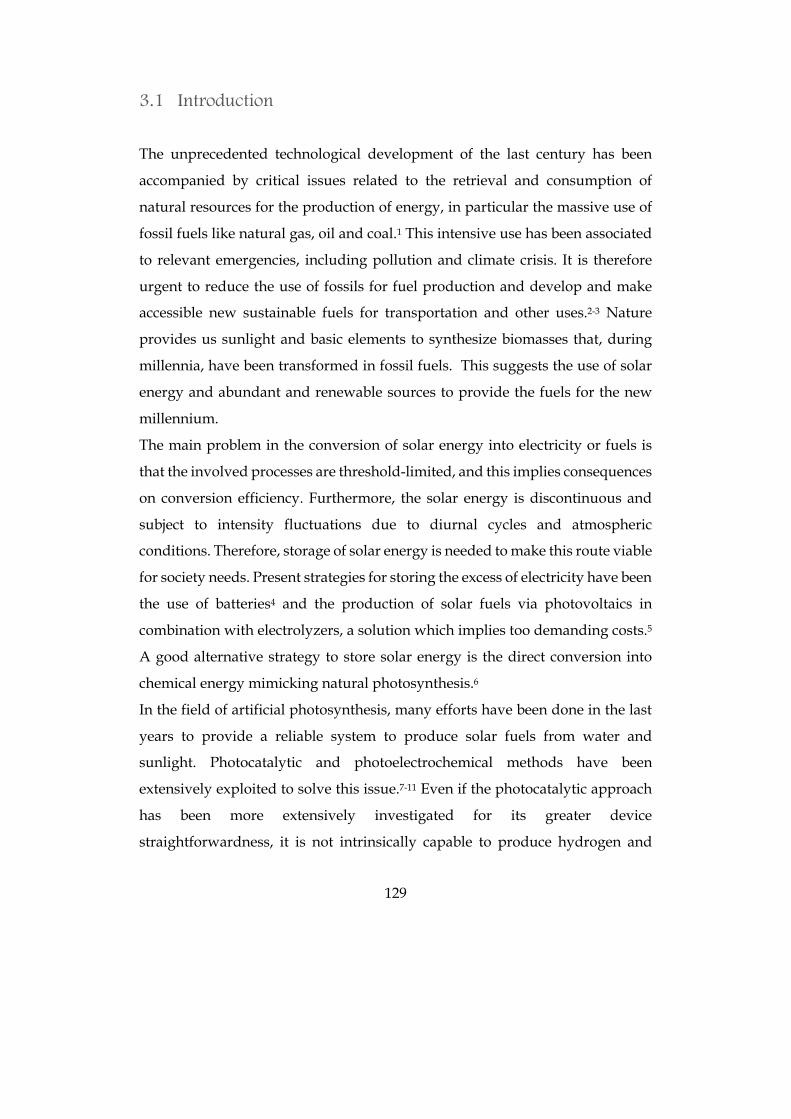
129
3.1 Introduction
The unprecedented technological development of the last century has been
accompanied by critical issues related to the retrieval and consumption of
natural resources for the production of energy, in particular the massive use of
fossil fuels like natural gas, oil and coal.1 This intensive use has been associated
to relevant emergencies, including pollution and climate crisis. It is therefore
urgent to reduce the use of fossils for fuel production and develop and make
accessible new sustainable fuels for transportation and other uses.2-3 Nature
provides us sunlight and basic elements to synthesize biomasses that, during
millennia, have been transformed in fossil fuels. This suggests the use of solar
energy and abundant and renewable sources to provide the fuels for the new
millennium.
The main problem in the conversion of solar energy into electricity or fuels is
that the involved processes are threshold-limited, and this implies consequences
on conversion efficiency. Furthermore, the solar energy is discontinuous and
subject to intensity fluctuations due to diurnal cycles and atmospheric
conditions. Therefore, storage of solar energy is needed to make this route viable
for society needs. Present strategies for storing the excess of electricity have been
the use of batteries4 and the production of solar fuels via photovoltaics in
combination with electrolyzers, a solution which implies too demanding costs.5
A good alternative strategy to store solar energy is the direct conversion into
chemical energy mimicking natural photosynthesis.6
In the field of artificial photosynthesis, many efforts have been done in the last
years to provide a reliable system to produce solar fuels from water and
sunlight. Photocatalytic and photoelectrochemical methods have been
extensively exploited to solve this issue.7-11 Even if the photocatalytic approach
has been more extensively investigated for its greater device
straightforwardness, it is not intrinsically capable to produce hydrogen and
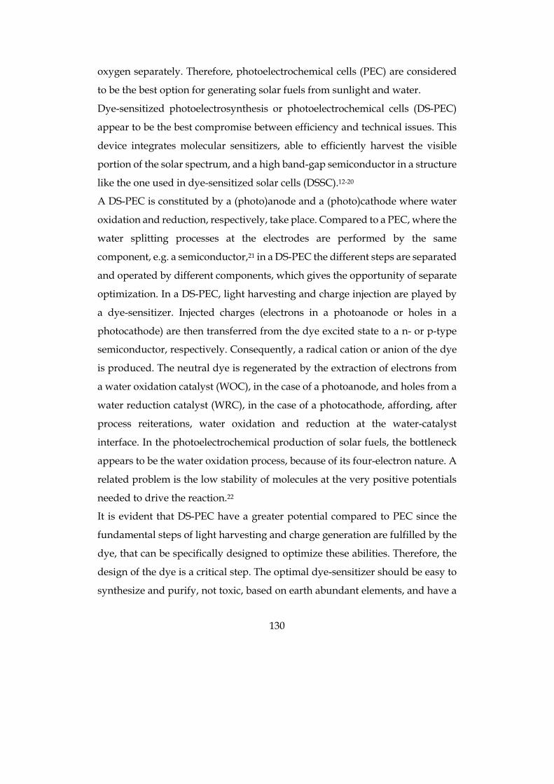
130
oxygen separately. Therefore, photoelectrochemical cells (PEC) are considered
to be the best option for generating solar fuels from sunlight and water.
Dye-sensitized photoelectrosynthesis or photoelectrochemical cells (DS-PEC)
appear to be the best compromise between efficiency and technical issues. This
device integrates molecular sensitizers, able to efficiently harvest the visible
portion of the solar spectrum, and a high band-gap semiconductor in a structure
like the one used in dye-sensitized solar cells (DSSC).12-20
A DS-PEC is constituted by a (photo)anode and a (photo)cathode where water
oxidation and reduction, respectively, take place. Compared to a PEC, where the
water splitting processes at the electrodes are performed by the same
component, e.g. a semiconductor,21 in a DS-PEC the different steps are separated
and operated by different components, which gives the opportunity of separate
optimization. In a DS-PEC, light harvesting and charge injection are played by
a dye-sensitizer. Injected charges (electrons in a photoanode or holes in a
photocathode) are then transferred from the dye excited state to a n- or p-type
semiconductor, respectively. Consequently, a radical cation or anion of the dye
is produced. The neutral dye is regenerated by the extraction of electrons from
a water oxidation catalyst (WOC), in the case of a photoanode, and holes from a
water reduction catalyst (WRC), in the case of a photocathode, affording, after
process reiterations, water oxidation and reduction at the water-catalyst
interface. In the photoelectrochemical production of solar fuels, the bottleneck
appears to be the water oxidation process, because of its four-electron nature. A
related problem is the low stability of molecules at the very positive potentials
needed to drive the reaction.22
It is evident that DS-PEC have a greater potential compared to PEC since the
fundamental steps of light harvesting and charge generation are fulfilled by the
dye, that can be specifically designed to optimize these abilities. Therefore, the
design of the dye is a critical step. The optimal dye-sensitizer should be easy to
synthesize and purify, not toxic, based on earth abundant elements, and have a
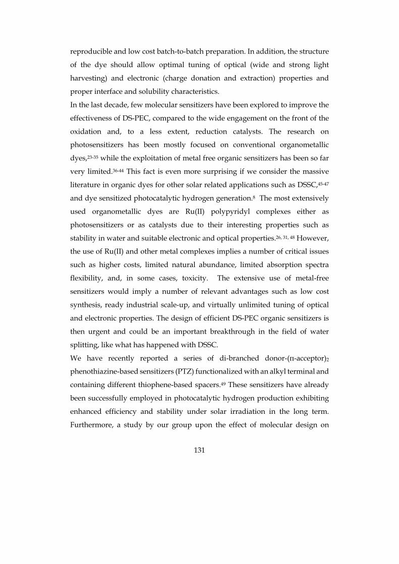
131
reproducible and low cost batch-to-batch preparation. In addition, the structure
of the dye should allow optimal tuning of optical (wide and strong light
harvesting) and electronic (charge donation and extraction) properties and
proper interface and solubility characteristics.
In the last decade, few molecular sensitizers have been explored to improve the
effectiveness of DS-PEC, compared to the wide engagement on the front of the
oxidation and, to a less extent, reduction catalysts. The research on
photosensitizers has been mostly focused on conventional organometallic
dyes,23-35 while the exploitation of metal free organic sensitizers has been so far
very limited.36-44 This fact is even more surprising if we consider the massive
literature in organic dyes for other solar related applications such as DSSC,45-47
and dye sensitized photocatalytic hydrogen generation.8 The most extensively
used organometallic dyes are Ru(II) polypyridyl complexes either as
photosensitizers or as catalysts due to their interesting properties such as
stability in water and suitable electronic and optical properties.26, 31, 48 However,
the use of Ru(II) and other metal complexes implies a number of critical issues
such as higher costs, limited natural abundance, limited absorption spectra
flexibility, and, in some cases, toxicity. The extensive use of metal-free
sensitizers would imply a number of relevant advantages such as low cost
synthesis, ready industrial scale-up, and virtually unlimited tuning of optical
and electronic properties. The design of efficient DS-PEC organic sensitizers is
then urgent and could be an important breakthrough in the field of water
splitting, like what has happened with DSSC.
We have recently reported a series of di-branched donor-(π-acceptor)2
phenothiazine-based sensitizers (PTZ) functionalized with an alkyl terminal and
containing different thiophene-based spacers.49 These sensitizers have already
been successfully employed in photocatalytic hydrogen production exhibiting
enhanced efficiency and stability under solar irradiation in the long term.
Furthermore, a study by our group upon the effect of molecular design on
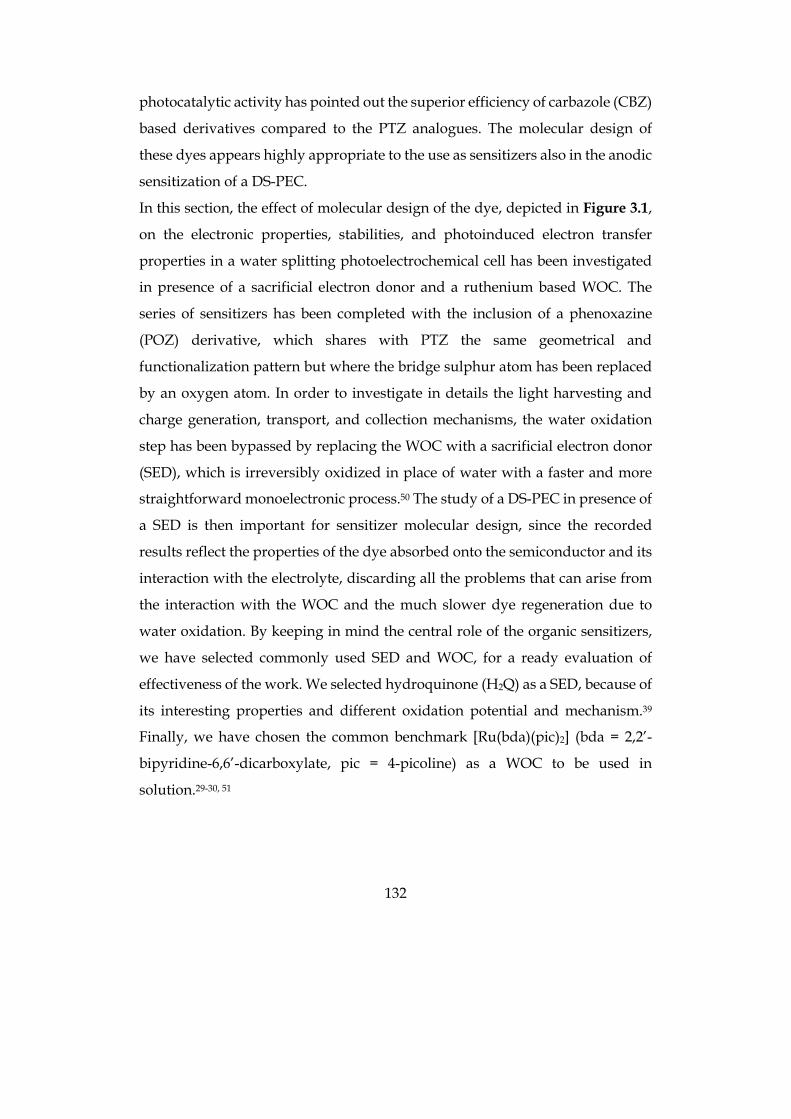
132
photocatalytic activity has pointed out the superior efficiency of carbazole (CBZ)
based derivatives compared to the PTZ analogues. The molecular design of
these dyes appears highly appropriate to the use as sensitizers also in the anodic
sensitization of a DS-PEC.
In this section, the effect of molecular design of the dye, depicted in Figure 3.1,
on the electronic properties, stabilities, and photoinduced electron transfer
properties in a water splitting photoelectrochemical cell has been investigated
in presence of a sacrificial electron donor and a ruthenium based WOC. The
series of sensitizers has been completed with the inclusion of a phenoxazine
(POZ) derivative, which shares with PTZ the same geometrical and
functionalization pattern but where the bridge sulphur atom has been replaced
by an oxygen atom. In order to investigate in details the light harvesting and
charge generation, transport, and collection mechanisms, the water oxidation
step has been bypassed by replacing the WOC with a sacrificial electron donor
(SED), which is irreversibly oxidized in place of water with a faster and more
straightforward monoelectronic process.50 The study of a DS-PEC in presence of
a SED is then important for sensitizer molecular design, since the recorded
results reflect the properties of the dye absorbed onto the semiconductor and its
interaction with the electrolyte, discarding all the problems that can arise from
the interaction with the WOC and the much slower dye regeneration due to
water oxidation. By keeping in mind the central role of the organic sensitizers,
we have selected commonly used SED and WOC, for a ready evaluation of
effectiveness of the work. We selected hydroquinone (H2Q) as a SED, because of
its interesting properties and different oxidation potential and mechanism.39
Finally, we have chosen the common benchmark [Ru(bda)(pic)2] (bda = 2,2’-
bipyridine-6,6’-dicarboxylate, pic = 4-picoline) as a WOC to be used in
solution.29-30, 51
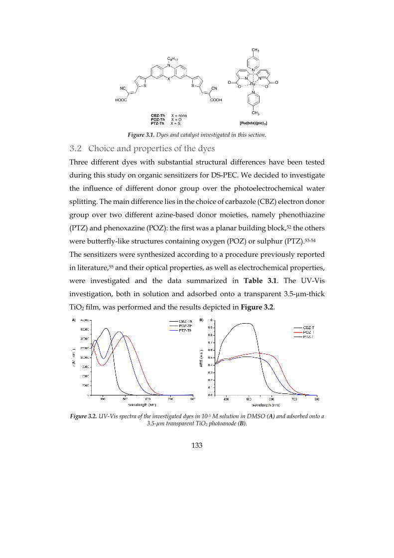
133
Figure 3.1. Dyes and catalyst investigated in this section.
3.2 Choice and properties of the dyes
Three different dyes with substantial structural differences have been tested
during this study on organic sensitizers for DS-PEC. We decided to investigate
the influence of different donor group over the photoelectrochemical water
splitting. The main difference lies in the choice of carbazole (CBZ) electron donor
group over two different azine-based donor moieties, namely phenothiazine
(PTZ) and phenoxazine (POZ): the first was a planar building block,52 the others
were butterfly-like structures containing oxygen (POZ) or sulphur (PTZ).53-54
The sensitizers were synthesized according to a procedure previously reported
in literature,55 and their optical properties, as well as electrochemical properties,
were investigated and the data summarized in Table 3.1. The UV-Vis
investigation, both in solution and adsorbed onto a transparent 3.5-µm-thick
TiO2 film, was performed and the results depicted in Figure 3.2.
Figure 3.2. UV-Vis spectra of the investigated dyes in 10-5 M solution in DMSO (A) and adsorbed onto a
3.5-µm transparent TiO2 photoanode (B).
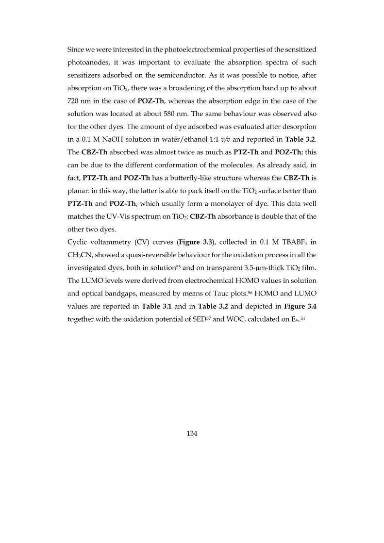
134
Since we were interested in the photoelectrochemical properties of the sensitized
photoanodes, it was important to evaluate the absorption spectra of such
sensitizers adsorbed on the semiconductor. As it was possible to notice, after
absorption on TiO2, there was a broadening of the absorption band up to about
720 nm in the case of POZ-Th, whereas the absorption edge in the case of the
solution was located at about 580 nm. The same behaviour was observed also
for the other dyes. The amount of dye adsorbed was evaluated after desorption
in a 0.1 M NaOH solution in water/ethanol 1:1 v/v and reported in Table 3.2.
The CBZ-Th absorbed was almost twice as much as PTZ-Th and POZ-Th; this
can be due to the different conformation of the molecules. As already said, in
fact, PTZ-Th and POZ-Th has a butterfly-like structure whereas the CBZ-Th is
planar: in this way, the latter is able to pack itself on the TiO2 surface better than
PTZ-Th and POZ-Th, which usually form a monolayer of dye. This data well
matches the UV-Vis spectrum on TiO2: CBZ-Th absorbance is double that of the
other two dyes.
Cyclic voltammetry (CV) curves (Figure 3.3), collected in 0.1 M TBABF4 in
CH3CN, showed a quasi-reversible behaviour for the oxidation process in all the
investigated dyes, both in solution55 and on transparent 3.5-µm-thick TiO2 film.
The LUMO levels were derived from electrochemical HOMO values in solution
and optical bandgaps, measured by means of Tauc plots.56 HOMO and LUMO
values are reported in Table 3.1 and in Table 3.2 and depicted in Figure 3.4
together with the oxidation potential of SED57 and WOC, calculated on E½.51
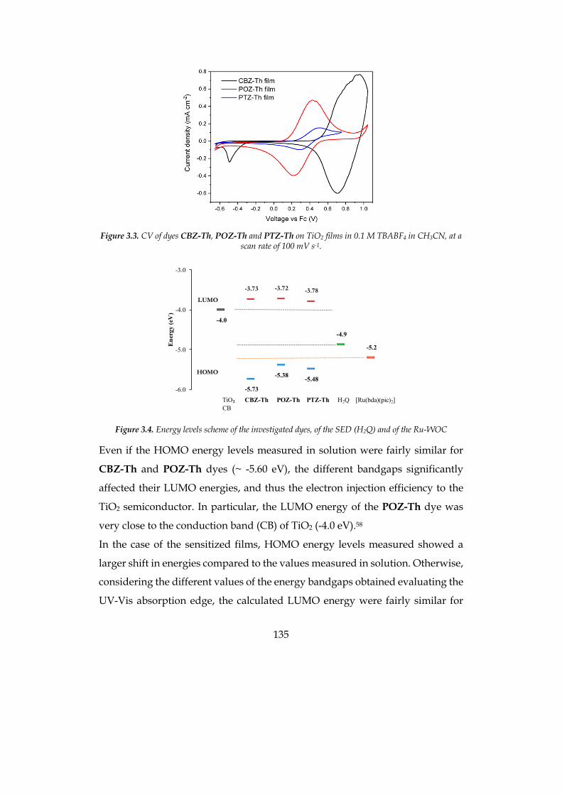
135
Figure 3.3. CV of dyes CBZ-Th, POZ-Th and PTZ-Th on TiO2 films in 0.1 M TBABF4 in CH3CN, at a
scan rate of 100 mV s-1.
Figure 3.4. Energy levels scheme of the investigated dyes, of the SED (H2Q) and of the Ru-WOC
Even if the HOMO energy levels measured in solution were fairly similar for
CBZ-Th and POZ-Th dyes (~ -5.60 eV), the different bandgaps significantly
affected their LUMO energies, and thus the electron injection efficiency to the
TiO2 semiconductor. In particular, the LUMO energy of the POZ-Th dye was
very close to the conduction band (CB) of TiO2 (-4.0 eV).58
In the case of the sensitized films, HOMO energy levels measured showed a
larger shift in energies compared to the values measured in solution. Otherwise,
considering the different values of the energy bandgaps obtained evaluating the
UV-Vis absorption edge, the calculated LUMO energy were fairly similar for
-4.0
-5.73
-5.38 -5.48
-4.9
-5.2
-3.73 -3.72 -3.78
-6.0
-5.0
-4.0
-3.0
Ene
rgy
(eV
)
LUMO
HOMO
TiO₂ CBZ-Th POZ-Th PTZ-Th H2Q [Ru(bda)(pic)2]CB
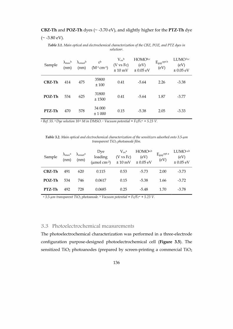
136
CBZ-Th and POZ-Th dyes (~ -3.70 eV), and slightly higher for the PTZ-Th dye
(~ -3.80 eV). Table 3.1. Main optical and electrochemical characterization of the CBZ, POZ, and PTZ dyes in
solutiona.
Sample λmaxb (nm)
λonsetb (nm)
εb (M-1 cm-1)
Voxb (V vs Fc) ± 10 mV
HOMOb,c (eV)
± 0.05 eV
Egapopt b (eV)
LUMO b,c (eV)
± 0.05 eV
CBZ-Th 414 475 35800 ± 100
0.41 -5.64 2.26 -3.38
POZ-Th 534 625 31800 ± 1500
0.41 -5.64 1.87 -3.77
PTZ-Th 470 578 34 000 ± 1 000
0.15 -5.38 2.05 -3.33
a Ref. 55. b Dye solution 10-5 M in DMSO. c Vacuum potential = Fc/Fc+ + 5.23 V.
Table 3.2. Main optical and electrochemical characterization of the sensitizers adsorbed onto 3.5-µm
transparent TiO2 photoanode film.
Sample λmaxa (nm)
λonseta (nm)
Dye loading
(µmol cm-2)
Voxa (V vs Fc) ± 10 mV
HOMOa,b (eV)
± 0.05 eV
Egapopt a (eV)
LUMO a,b (eV)
± 0.05 eV
CBZ-Th 491 620 0.115 0.53 -5.73 2.00 -3.73
POZ-Th 534 746 0.0617 0.15 -5.38 1.66 -3.72
PTZ-Th 492 728 0.0685 0.25 -5.48 1.70 -3.78
a 3.5-µm transparent TiO2 photoanode. b Vacuum potential = Fc/Fc+ + 5.23 V.
3.3 Photoelectrochemical measurements The photoelectrochemical characterization was performed in a three-electrode
configuration purpose-designed photoelectrochemical cell (Figure 3.5). The
sensitized TiO2 photoanodes (prepared by screen-printing a commercial TiO2
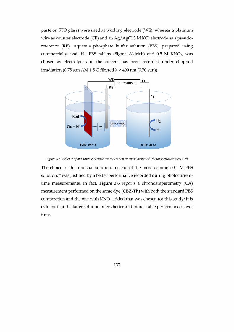
137
paste on FTO glass) were used as working electrode (WE), whereas a platinum
wire as counter electrode (CE) and an Ag/AgCl 3 M KCl electrode as a pseudo-
reference (RE). Aqueous phosphate buffer solution (PBS), prepared using
commercially available PBS tablets (Sigma Aldrich) and 0.5 M KNO3, was
chosen as electrolyte and the current has been recorded under chopped
irradiation (0.75 sun AM 1.5 G filtered l > 400 nm (0.70 sun)).
Figure 3.5. Scheme of our three-electrode configuration purpose-designed PhotoElectrochemical Cell.
The choice of this unusual solution, instead of the more common 0.1 M PBS
solution,39 was justified by a better performance recorded during photocurrent-
time measurements. In fact, Figure 3.6 reports a chronoamperometry (CA)
measurement performed on the same dye (CBZ-Th) with both the standard PBS
composition and the one with KNO3 added that was chosen for this study; it is
evident that the latter solution offers better and more stable performances over
time.
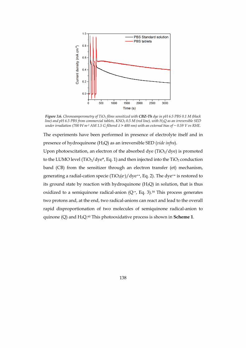
138
Figure 3.6. Chronoamperometry of TiO2 films sensitized with CBZ-Th dye in pH 6.5 PBS 0.1 M (black line) and pH 6.5 PBS from commercial tablets, KNO3 0.5 M (red line), with H2Q as an irreversible SED under irradiation (700 W m-2 AM 1.5 G filtered l > 400 nm) with an external bias of ~ 0.59 V vs RHE.
The experiments have been performed in presence of electrolyte itself and in
presence of hydroquinone (H2Q) as an irreversible SED (vide infra).
Upon photoexcitation, an electron of the absorbed dye (TiO2/dye) is promoted
to the LUMO level (TiO2/dye*, Eq. 1) and then injected into the TiO2 conduction
band (CB) from the sensitizer through an electron transfer (et) mechanism,
generating a radial-cation specie (TiO2(e-)/dye+•, Eq. 2). The dye+• is restored to
its ground state by reaction with hydroquinone (H2Q) in solution, that is thus
oxidized to a semiquinone radical-anion (Q-•, Eq. 3).59 This process generates
two protons and, at the end, two radical-anions can react and lead to the overall
rapid disproportionation of two molecules of semiquinone radical-anion to
quinone (Q) and H2Q.60 This photooxidative process is shown in Scheme 1.
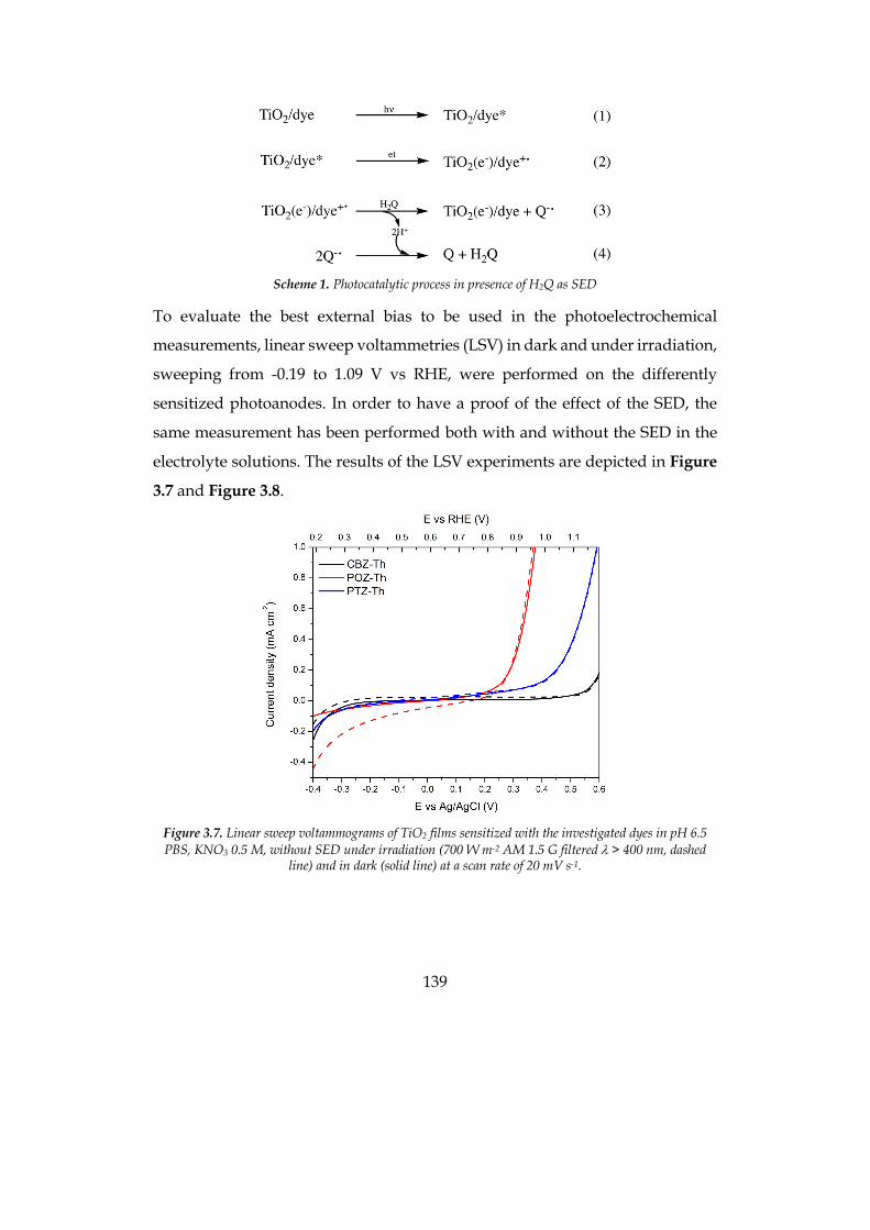
139
Scheme 1. Photocatalytic process in presence of H2Q as SED
To evaluate the best external bias to be used in the photoelectrochemical
measurements, linear sweep voltammetries (LSV) in dark and under irradiation,
sweeping from -0.19 to 1.09 V vs RHE, were performed on the differently
sensitized photoanodes. In order to have a proof of the effect of the SED, the
same measurement has been performed both with and without the SED in the
electrolyte solutions. The results of the LSV experiments are depicted in Figure
3.7 and Figure 3.8.
Figure 3.7. Linear sweep voltammograms of TiO2 films sensitized with the investigated dyes in pH 6.5 PBS, KNO3 0.5 M, without SED under irradiation (700 W m-2 AM 1.5 G filtered l > 400 nm, dashed
line) and in dark (solid line) at a scan rate of 20 mV s-1.
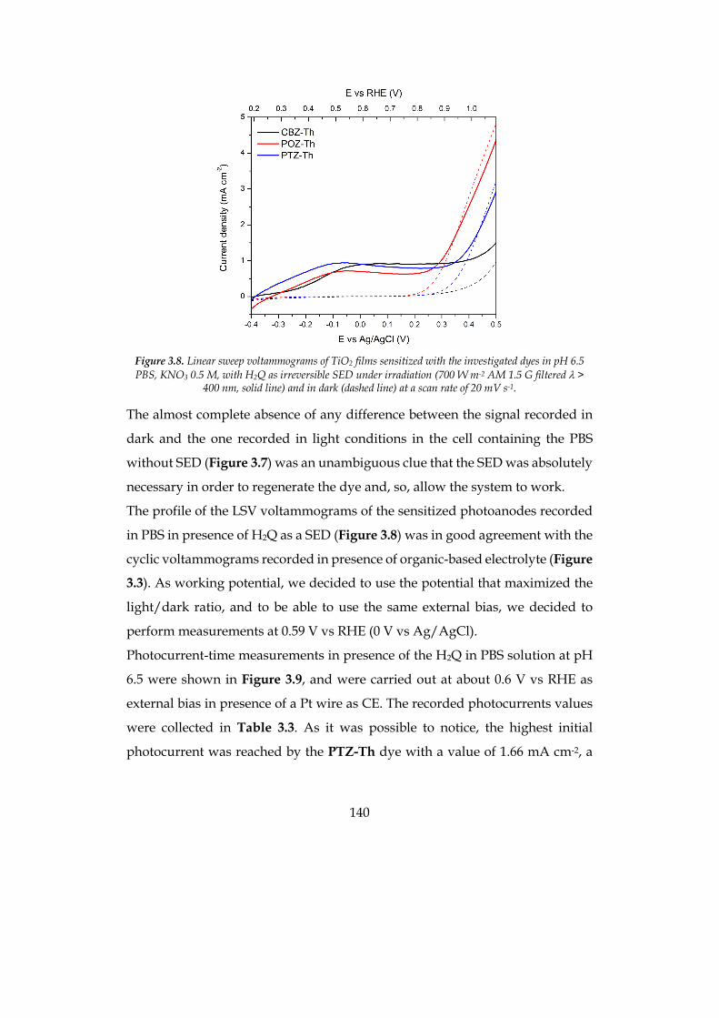
140
Figure 3.8. Linear sweep voltammograms of TiO2 films sensitized with the investigated dyes in pH 6.5 PBS, KNO3 0.5 M, with H2Q as irreversible SED under irradiation (700 W m-2 AM 1.5 G filtered l >
400 nm, solid line) and in dark (dashed line) at a scan rate of 20 mV s-1.
The almost complete absence of any difference between the signal recorded in
dark and the one recorded in light conditions in the cell containing the PBS
without SED (Figure 3.7) was an unambiguous clue that the SED was absolutely
necessary in order to regenerate the dye and, so, allow the system to work.
The profile of the LSV voltammograms of the sensitized photoanodes recorded
in PBS in presence of H2Q as a SED (Figure 3.8) was in good agreement with the
cyclic voltammograms recorded in presence of organic-based electrolyte (Figure
3.3). As working potential, we decided to use the potential that maximized the
light/dark ratio, and to be able to use the same external bias, we decided to
perform measurements at 0.59 V vs RHE (0 V vs Ag/AgCl).
Photocurrent-time measurements in presence of the H2Q in PBS solution at pH
6.5 were shown in Figure 3.9, and were carried out at about 0.6 V vs RHE as
external bias in presence of a Pt wire as CE. The recorded photocurrents values
were collected in Table 3.3. As it was possible to notice, the highest initial
photocurrent was reached by the PTZ-Th dye with a value of 1.66 mA cm-2, a
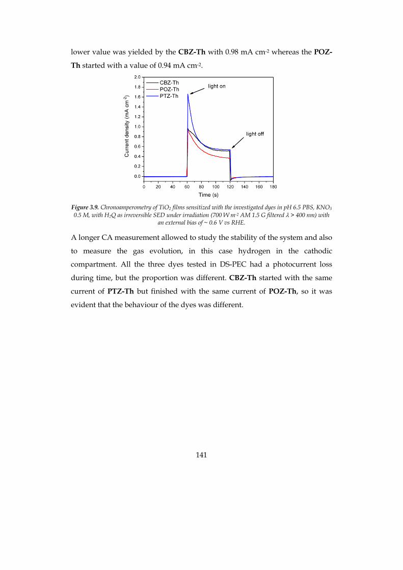
141
lower value was yielded by the CBZ-Th with 0.98 mA cm-2 whereas the POZ-
Th started with a value of 0.94 mA cm-2.
Figure 3.9. Chronoamperometry of TiO2 films sensitized with the investigated dyes in pH 6.5 PBS, KNO3 0.5 M, with H2Q as irreversible SED under irradiation (700 W m-2 AM 1.5 G filtered l > 400 nm) with
an external bias of ~ 0.6 V vs RHE.
A longer CA measurement allowed to study the stability of the system and also
to measure the gas evolution, in this case hydrogen in the cathodic
compartment. All the three dyes tested in DS-PEC had a photocurrent loss
during time, but the proportion was different. CBZ-Th started with the same
current of PTZ-Th but finished with the same current of POZ-Th, so it was
evident that the behaviour of the dyes was different.
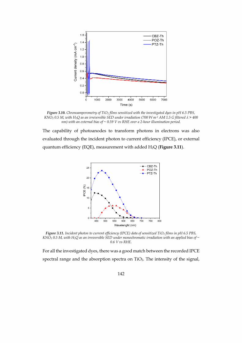
142
Figure 3.10. Chronoamperometry of TiO2 films sensitized with the investigated dyes in pH 6.5 PBS,
KNO3 0.5 M, with H2Q as an irreversible SED under irradiation (700 W m-2 AM 1.5 G filtered l > 400 nm) with an external bias of ~ 0.59 V vs RHE over a 2-hour illumination period.
The capability of photoanodes to transform photons in electrons was also
evaluated through the incident photon to current efficiency (IPCE), or external
quantum efficiency (EQE), measurement with added H2Q (Figure 3.11).
Figure 3.11. Incident photon to current efficiency (IPCE) data of sensitized TiO2 films in pH 6.5 PBS,
KNO3 0.5 M, with H2Q as an irreversible SED under monochromatic irradiation with an applied bias of ~ 0.6 V vs RHE.
For all the investigated dyes, there was a good match between the recorded IPCE
spectral range and the absorption spectra on TiO2. The intensity of the signal,
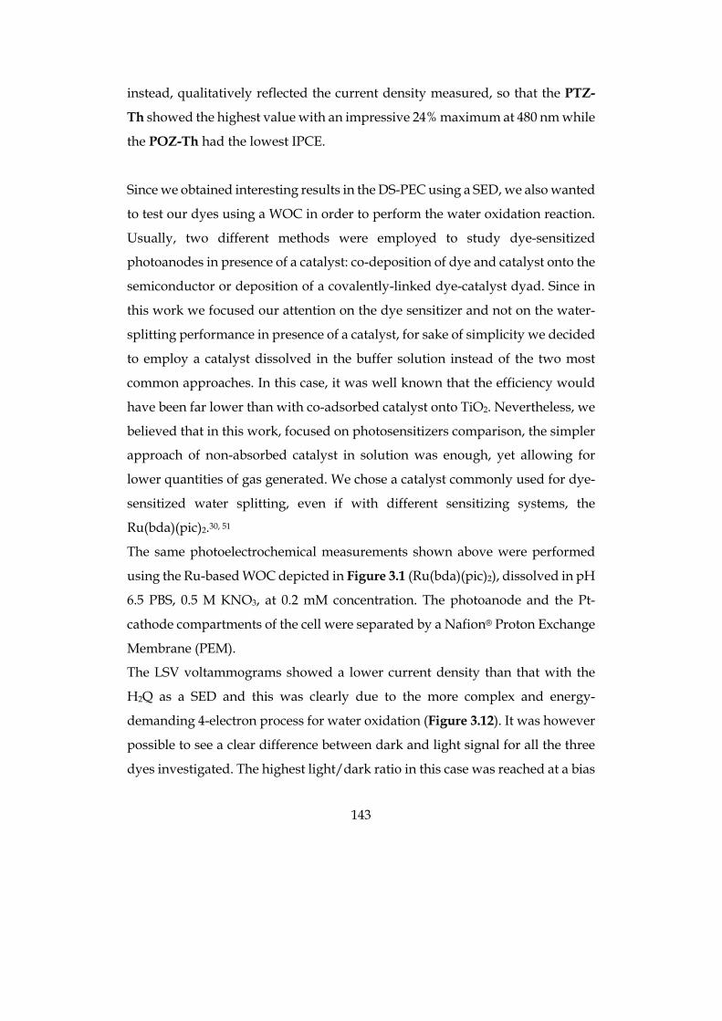
143
instead, qualitatively reflected the current density measured, so that the PTZ-
Th showed the highest value with an impressive 24% maximum at 480 nm while
the POZ-Th had the lowest IPCE.
Since we obtained interesting results in the DS-PEC using a SED, we also wanted
to test our dyes using a WOC in order to perform the water oxidation reaction.
Usually, two different methods were employed to study dye-sensitized
photoanodes in presence of a catalyst: co-deposition of dye and catalyst onto the
semiconductor or deposition of a covalently-linked dye-catalyst dyad. Since in
this work we focused our attention on the dye sensitizer and not on the water-
splitting performance in presence of a catalyst, for sake of simplicity we decided
to employ a catalyst dissolved in the buffer solution instead of the two most
common approaches. In this case, it was well known that the efficiency would
have been far lower than with co-adsorbed catalyst onto TiO2. Nevertheless, we
believed that in this work, focused on photosensitizers comparison, the simpler
approach of non-absorbed catalyst in solution was enough, yet allowing for
lower quantities of gas generated. We chose a catalyst commonly used for dye-
sensitized water splitting, even if with different sensitizing systems, the
Ru(bda)(pic)2.30, 51
The same photoelectrochemical measurements shown above were performed
using the Ru-based WOC depicted in Figure 3.1 (Ru(bda)(pic)2), dissolved in pH
6.5 PBS, 0.5 M KNO3, at 0.2 mM concentration. The photoanode and the Pt-
cathode compartments of the cell were separated by a Nafion® Proton Exchange
Membrane (PEM).
The LSV voltammograms showed a lower current density than that with the
H2Q as a SED and this was clearly due to the more complex and energy-
demanding 4-electron process for water oxidation (Figure 3.12). It was however
possible to see a clear difference between dark and light signal for all the three
dyes investigated. The highest light/dark ratio in this case was reached at a bias
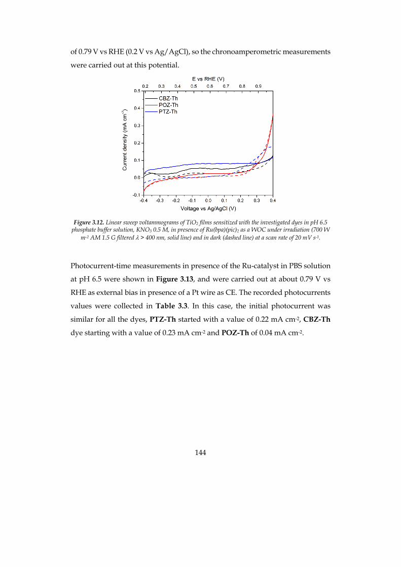
144
of 0.79 V vs RHE (0.2 V vs Ag/AgCl), so the chronoamperometric measurements
were carried out at this potential.
Figure 3.12. Linear sweep voltammograms of TiO2 films sensitized with the investigated dyes in pH 6.5
phosphate buffer solution, KNO3 0.5 M, in presence of Ru(bpa)(pic)2 as a WOC under irradiation (700 W m-2 AM 1.5 G filtered l > 400 nm, solid line) and in dark (dashed line) at a scan rate of 20 mV s-1.
Photocurrent-time measurements in presence of the Ru-catalyst in PBS solution
at pH 6.5 were shown in Figure 3.13, and were carried out at about 0.79 V vs
RHE as external bias in presence of a Pt wire as CE. The recorded photocurrents
values were collected in Table 3.3. In this case, the initial photocurrent was
similar for all the dyes, PTZ-Th started with a value of 0.22 mA cm-2, CBZ-Th
dye starting with a value of 0.23 mA cm-2 and POZ-Th of 0.04 mA cm-2.
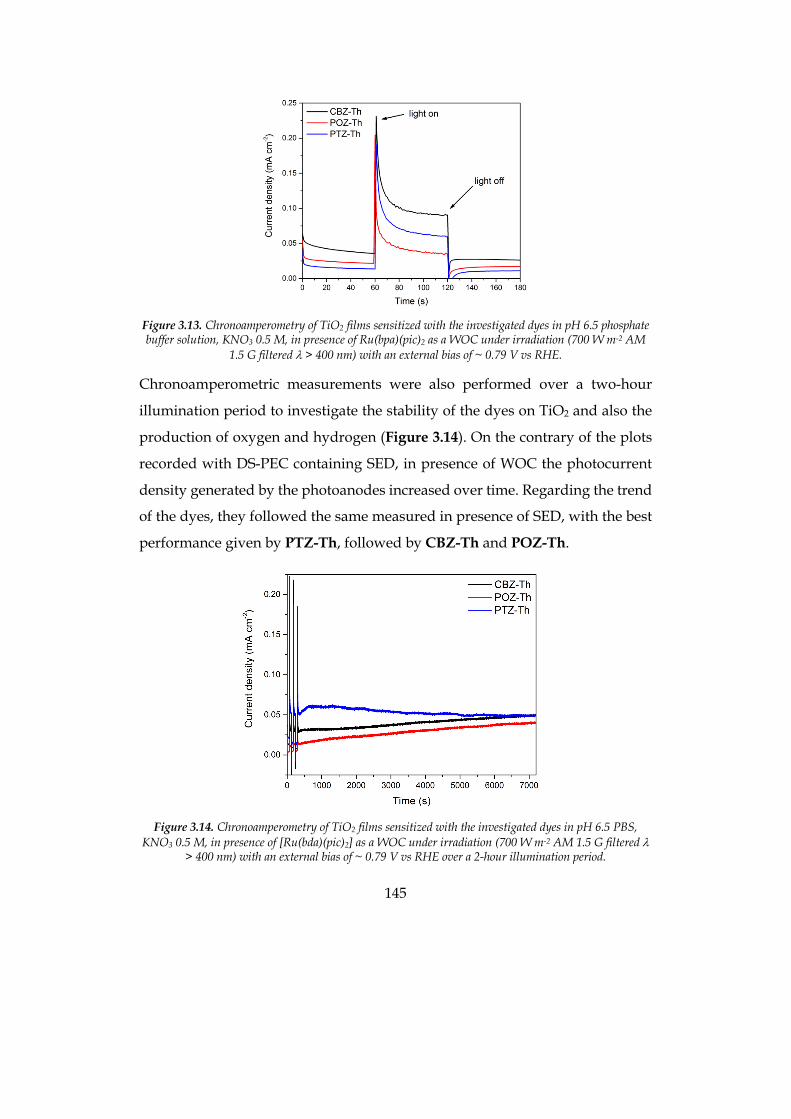
145
Figure 3.13. Chronoamperometry of TiO2 films sensitized with the investigated dyes in pH 6.5 phosphate buffer solution, KNO3 0.5 M, in presence of Ru(bpa)(pic)2 as a WOC under irradiation (700 W m-2 AM
1.5 G filtered l > 400 nm) with an external bias of ~ 0.79 V vs RHE.
Chronoamperometric measurements were also performed over a two-hour
illumination period to investigate the stability of the dyes on TiO2 and also the
production of oxygen and hydrogen (Figure 3.14). On the contrary of the plots
recorded with DS-PEC containing SED, in presence of WOC the photocurrent
density generated by the photoanodes increased over time. Regarding the trend
of the dyes, they followed the same measured in presence of SED, with the best
performance given by PTZ-Th, followed by CBZ-Th and POZ-Th.
Figure 3.14. Chronoamperometry of TiO2 films sensitized with the investigated dyes in pH 6.5 PBS,
KNO3 0.5 M, in presence of [Ru(bda)(pic)2] as a WOC under irradiation (700 W m-2 AM 1.5 G filtered l > 400 nm) with an external bias of ~ 0.79 V vs RHE over a 2-hour illumination period.
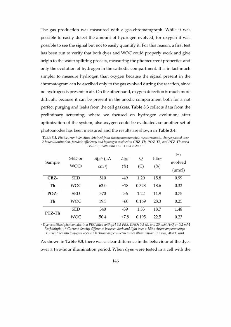
146
The gas production was measured with a gas-chromatograph. While it was
possible to easily detect the amount of hydrogen evolved, for oxygen it was
possible to see the signal but not to easily quantify it. For this reason, a first test
has been run to verify that both dyes and WOC could properly work and give
origin to the water splitting process, measuring the photocurrent properties and
only the evolution of hydrogen in the cathodic compartment. It is in fact much
simpler to measure hydrogen than oxygen because the signal present in the
chromatogram can be ascribed only to the gas evolved during the reaction, since
no hydrogen is present in air. On the other hand, oxygen detection is much more
difficult, because it can be present in the anodic compartment both for a not
perfect purging and leaks from the cell gaskets. Table 3.3 collects data from the
preliminary screening, where we focused on hydrogen evolution; after
optimization of the system, also oxygen could be evaluated, so another set of
photoanodes has been measured and the results are shown in Table 3.4. Table 3.3. Photocurrent densities obtained from chronoamperometric measurements, charge passed over 2-hour illumination, faradaic efficiency and hydrogen evolved in CBZ-Th, POZ-Th, and PTZ-Th based
DS-PEC, both with a SED and a WOC.
Sample SED or
WOCa
𝛥jd-lb (µA
cm-2)
𝛥j2hc
(%)
Q
(C)
FEH2
(%)
H2
evolved
(µmol)
CBZ-
Th
SED 510 -49 1.20 15.8 0.99
WOC 63.0 +18 0.328 18.6 0.32
POZ-
Th
SED 370 -36 1.22 11.9 0.75
WOC 19.5 +60 0.169 28.3 0.25
PTZ-Th SED 540 -39 1.53 18.7 1.48
WOC 50.4 +7.8 0.195 22.5 0.23 a Dye-sensitized photoanodes in a PEC filled with pH 6.5 PBS, KNO3 0.5 M, and 20 mM H2Q or 0.2 mM
Ru(bda)(pic)2; b Current density difference between dark and light over a 180 s chronoamperometry; c Current density loss/gain over a 2 h chronoamperometry under illumination (0.7 sun, 𝛌>400 nm).
As shown in Table 3.3, there was a clear difference in the behaviour of the dyes
over a two-hour illumination period. When dyes were tested in a cell with the
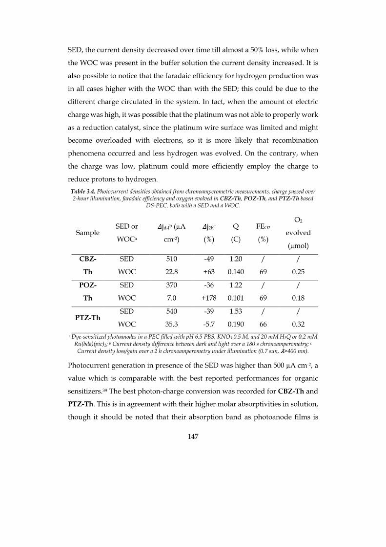
147
SED, the current density decreased over time till almost a 50% loss, while when
the WOC was present in the buffer solution the current density increased. It is
also possible to notice that the faradaic efficiency for hydrogen production was
in all cases higher with the WOC than with the SED; this could be due to the
different charge circulated in the system. In fact, when the amount of electric
charge was high, it was possible that the platinum was not able to properly work
as a reduction catalyst, since the platinum wire surface was limited and might
become overloaded with electrons, so it is more likely that recombination
phenomena occurred and less hydrogen was evolved. On the contrary, when
the charge was low, platinum could more efficiently employ the charge to
reduce protons to hydrogen. Table 3.4. Photocurrent densities obtained from chronoamperometric measurements, charge passed over 2-hour illumination, faradaic efficiency and oxygen evolved in CBZ-Th, POZ-Th, and PTZ-Th based
DS-PEC, both with a SED and a WOC.
Sample SED or
WOCa
𝛥jd-lb (µA
cm-2)
𝛥j2hc
(%)
Q
(C)
FEO2
(%)
O2
evolved
(µmol)
CBZ-
Th
SED 510 -49 1.20 / /
WOC 22.8 +63 0.140 69 0.25
POZ-
Th
SED 370 -36 1.22 / /
WOC 7.0 +178 0.101 69 0.18
PTZ-Th SED 540 -39 1.53 / /
WOC 35.3 -5.7 0.190 66 0.32 a Dye-sensitized photoanodes in a PEC filled with pH 6.5 PBS, KNO3 0.5 M, and 20 mM H2Q or 0.2 mM
Ru(bda)(pic)2; b Current density difference between dark and light over a 180 s chronoamperometry; c Current density loss/gain over a 2 h chronoamperometry under illumination (0.7 sun, 𝛌>400 nm).
Photocurrent generation in presence of the SED was higher than 500 µA cm-2, a
value which is comparable with the best reported performances for organic
sensitizers.39 The best photon-charge conversion was recorded for CBZ-Th and
PTZ-Th. This is in agreement with their higher molar absorptivities in solution,
though it should be noted that their absorption band as photoanode films is
148
blue-shifted compared to the POZ derivative. Indeed, the higher generated
current values of CBZ-Th and PTZ-Th well matched their improved IPCE
behaviour. Since on the whole the optical properties of CBZ-Th and PTZ-Th
both in solution or as films are not better than those of POZ-Th, we conclude
that the superior external quantum efficiency of the two more performing dyes,
which comprises the light harvesting ability and the internal quantum
efficiency, mainly arises from a higher value of the latter parameter. IPCE also
partially accounts for the higher photoelectrochemical performance of PTZ-Th
compared to CBZ-Th. It should also be noted that the amount of generated
charge is higher for PTZ-Th despite its lower loading on the semiconductor. We
therefore argue that the lower loading (likely arising from the butterfly
geometry), associated to a suppression of detrimental dye–dye intermolecular
excited state self-quenching, might play a central role in the enhanced
performances. The data in presence of the WOC shows the same trend seen with
the SED and confirms that the most efficient system is the PTZ-Th dye. Finally,
we note that the use of the dyes in combination with a WOC revealed a stable
photocurrent generation over a considerable time for all the three sensitizers,
designating them as promising alternatives to the more common Ru-based
complexes.
The amount of both evolved hydrogen and oxygen follows the same trend as for
charge generation and collection. In particular, the amount of evolved gas at the
CE is in the rank PTZ-Th > CBZ-Th > POZ-Th, in agreement with the
aforementioned discussion. These values quantitatively well compare with gas
generation properties previously reported in the recent literature for organic
sensitizers.61 Such evaluation is even more favourable if considering that the
other representative reported measurements are carried out at much higher (up
to 3 sun) intensities, to be compared with our device set-up at 0.70 sun.51
149
3.4 Experimental section
The following materials were purchased from commercial suppliers: FTO-
coated glass plates (2.2 mm thick; sheet resistance ~7 ohm per square; Solaronix);
Dyesol 18NR-T transparent TiO2 blend of active 20 nm anatase particles. All
reagents were obtained from commercial suppliers at the highest purity grade
and used without further purification. The dyes and the catalyst have been
synthesized according to literature.30, 55
Absorption spectra were recorded with a V-570 Jasco spectrophotometer. UV-
O3 treatment was performed using Novascan PSD Pro Series – Digital UV Ozone
System. The thickness of the layers was measured by means of a VEECO Dektak
8 Stylus Profiler. Cyclic Voltammetry (CV) was carried out at scan rate of 100
mV s-1, using a AUTOLAB PGSTAT302N potentiostat in a three-electrode
electrochemical cell under Ar. The working, counter, and the pseudo-reference
electrodes were a glassy carbon pin for the dyes in solution or a sensitized 3.5
µm thick TiO2 film, a Pt wire and an Ag/AgCl electrode (3 M KCl), respectively.
The working electrodes discs were well polished with alumina 0.1 µm
suspension. The preparation and sensitization of the 3.5-µm-thick TiO2 film is
described below. The Pt wire was sonicated for 15 min in deionized water,
washed with 2-propanol, and cycled for 50 times in 0.5 M H2SO4 before use. The
Ag/AgCl pseudo-reference electrode was calibrated, by adding ferrocene (10-3
M) to the test solution after each measurement. All potentials have
been reported in the reversible hydrogen electrode (RHE) scale by shifting the
potentials by ERHE = EAg/AgCl + 0.059 pH + E°Ag/AgCl (KCl 3 M) = E Ag/AgCl + 0.059 ´ 6.5
+ 0.21 V = EAg/AgCl + 0.59 V, according to the literature.62
The photoanodes have been prepared as described below adapting a procedure
reported in the literature.63 In order to exclude metal contamination all of the
containers were in glass or Teflon and were treated with EtOH and 10% HCl
prior to use. Plastic spatulas and tweezers have been used throughout the
150
procedure. FTO glass plates were cleaned in a detergent solution for 15 min
using an ultrasonic bath, rinsed with pure water and EtOH. After treatment in a
UV-O3 system for 18 min, a transparent active layer of 4.25 cm2 was screen-
printed using Dyesol 18NR-T active transparent TiO2 paste. The coated films
were thermally treated at 125 °C for 6 min, 325 °C for 10 min, 450 °C for 15 min,
and 500 °C for 15 min. The heating ramp rate was 5 - 10 °C/min.
FTO plates coated with 3.5 µm transparent TiO2 film, prepared as described
above, were treated in a UV-O3 system for 20 min at room temperature, then
immersed into a 2 x 10⁻⁴ M solution in EtOH of the dye for 2 h at room
temperature in the dark. The stained substrates were rinsed with EtOH and
dried with a stream of dry nitrogen. The UV-Vis spectra, CV and LSV were
recorded in comparison with a bare 3.5 µm transparent TiO2 film.
Photoelectrochemical measurements of DS-PEC were carried out with black
metal mask on top of the photoanode of 0.50 cm2 surface area under a 500 W
Xenon light source (ABET Technologies Sun 2000 class ABA Solar Simulator).
The power of the simulated light was calibrated to 75 mW cm-2 (70 mW cm-2,
𝛌>400 nm) using a reference Si cell photodiode equipped with an IR-cutoff filter
(KG-5, Schott) to reduce the mismatch in the region of 350-750 nm between the
simulated light and the AM 1.5 spectrum. The LSV (scan rate 20 mV s-1) and CA
measurements on the DS-PEC were performed using a AUTOLAB
PGSTAT302N potentiostat in a three-electrode purposely designed
photoelectrochemical cell filled with pH 6.5 PBS (Sigma Aldrich, product
number P4417), KNO3 0.5 M under Ar in presence of a Nafion®-115 (Alfa Aesar)
proton exchange membrane, and the data collected with GPES electrochemical
interface (EcoChemie).
IPCE measurements were carried out using monochromatic light through a
monochromator (Jasco) illuminating on the active area of the working electrode
(0.50 cm2). The light intensity was monitored using a reference Si cell photodiode
(THORLABS, S120VC) and corrected to calculate the IPCE values. The current
151
intensity was measured using an AUTOLAB PGSTAT302N potentiostat in a
three-electrode purposely designed photoelectrochemical cell and the data
collected with GPES electrochemical interface (EcoChemie).
The gas production was measured by means of an Agilent 6850 gas-
chromatograph, using Ar as gas carrier (flow rate 25 mL min-1) and equipped
with thermal conductivity detector and a molecular sieve 5 Å column (2 m x 2
mmID, temperature 70 °C). Argon mixtures with 100 ppm and 10 000 ppm of H2
and O2 were used for calibration. Evolved O2 was calculated taking into account
small leaks of air into the PEC device: the amount of O2 coming from air was
subtracted from the total measured one (i.e. the quantity proportional to the
measured N2, surely coming from leaks).
152
3.5 Bibliography
1. 2016.”International Energy Agency”.
2. Armaroli, N.; Balzani, V., ”Towards an electricity-powered world”. Energy Environ. Sci. 2011, 4, 3193-3222, doi: 10.1039/C1EE01249E
3. Armaroli, N.; Balzani, V., ”Solar Electricity and Solar Fuels: Status and Perspectives in the Context of the Energy Transition”. Chem. Eur. J. 2016, 22, 32-57, doi: 10.1002/chem.201503580
4. Letcher, T., Storing Energy 1st edition ed.; Elsevier: 2016.
5. Armaroli, N.; Balzani, V., ”The Hydrogen Issue”. ChemSusChem 2010, 4, 21-36, doi: 10.1002/cssc.201000182
6. Barber, J., ”Photosynthetic energy conversion: natural and artificial”. Chem. Soc. Rev. 2009, 38, 185-196, doi: 10.1039/B802262N
7. Zhang, X.; Peng, T.; Song, S., ”Recent advances in dye-sensitized semiconductor systems for photocatalytic hydrogen production”. J. Mater. Chem. A 2016, 4, 2365-2402, doi: 10.1039/C5TA08939E
8. Cecconi, B.; Manfredi, N.; Montini, T.; Fornasiero, P.; Abbotto, A., ”Dye-Sensitized Solar Hydrogen Production: The Emerging Role of Metal-Free Organic Sensitizers”. Eur. J. Org. Chem. 2016, 2016, 5194-5215, doi: 10.1002/ejoc.201600653
9. Queyriaux, N.; Kaeffer, N.; Morozan, A.; Chavarot-Kerlidou, M.; Artero, V., ”Molecular cathode and photocathode materials for hydrogen evolution in photoelectrochemical devices”. J. Photochem. Photobiol. C: Photochem. Rev. 2015, 25, 90-105, doi: http://dx.doi.org/10.1016/j.jphotochemrev.2015.08.001
10. Barber, J.; Tran, P. D., ”From natural to artificial photosynthesis”. Journal of The Royal Society Interface 2013, 10, doi: 10.1098/rsif.2012.0984
153
11. Swierk, J. R.; Mallouk, T. E., ”Design and development of photoanodes for water-splitting dye-sensitized photoelectrochemical cells”. Chem. Soc. Rev. 2013, 42, 2357-2387, doi: Doi 10.1039/C2cs35246j
12. Alstrum-Acevedo, J. H.; Brennaman, M. K.; Meyer, T. J., ”Chemical Approaches to Artificial Photosynthesis. 2”. Inorg. Chem. 2005, 44, 6802-6827, doi: 10.1021/ic050904r
13. Concepcion, J. J.; House, R. L.; Papanikolas, J. M.; Meyer, T. J., ”Chemical approaches to artificial photosynthesis”. Proc. Natl. Acad. Sci. U.S.A. 2012, 109, 15560, doi:
14. Walter, M. G.; Warren, E. L.; McKone, J. R.; Boettcher, S. W.; Mi, Q.; Santori, E. A.; Lewis, N. S., ”Solar Water Splitting Cells”. Chem. Rev. 2010, 110, 6446-6473, doi: 10.1021/cr1002326
15. Balzani, V.; Credi, A.; Venturi, M., ”Photochemical Conversion of Solar Energy”. ChemSusChem 2008, 1, 26-58, doi: 10.1002/cssc.200700087
16. Grätzel, M., ”Photoelectrochemical cells”. Nature 2001, 414, 338, doi: 10.1038/35104607
17. Brennan, B. J.; Lam, Y. C.; Kim, P. M.; Zhang, X.; Brudvig, G. W., ”Photoelectrochemical Cells Utilizing Tunable Corroles”. ACS Appl. Mater. Interfaces 2015, 7, 16124-16130, doi: 10.1021/acsami.5b05050
18. Li, J.; Miao, J.; Long, G.; Zhang, J.; Li, Y.; Ganguly, R.; Zhao, Y.; Liu, Y.; Liu, B.; Zhang, Q., ”N-Heteroheptacenequinone and N-heterononacenequinone: synthesis, physical properties, crystal structures and photoelectrochemical behaviors”. J Mater Chem C 2015, 3, 9877-9884, doi: 10.1039/C5TC02010G
19. Wang, Z.; Miao, J.; Long, G.; Gu, P.; Li, J.; Aratani, N.; Yamada, H.; Liu, B.; Zhang, Q., ”Full Characterization and Photoelectrochemical Behavior of Pyrene-fused Octaazadecacene and Tetraazaoctacene”. Chem. Asian J. 2015, 11, 482-485, doi: 10.1002/asia.201501276
20. Gu, P.-Y.; Wang, Z.; Xiao, F.-X.; Lin, Z.; Song, R.; Xu, Q.-F.; Lu, J.-M.; Liu, B.; Zhang, Q., ”An ambipolar azaacene as a stable photocathode for metal-free light-driven water reduction”. Materials Chemistry Frontiers 2017, 1, 495-498, doi: 10.1039/C6QM00113K
154
21. Fujishima, A.; Honda, K., ”Electrochemical Photolysis of Water at a Semiconductor Electrode”. Nature 1972, 238, 37-38, doi:
22. Youngblood, W. J.; Lee, S.-H. A.; Maeda, K.; Mallouk, T. E., ”Visible Light Water Splitting Using Dye-Sensitized Oxide Semiconductors”. Acc. Chem. Res. 2009, 42, 1966-1973, doi: Doi 10.1021/Ar9002398
23. Zhang, L.; Gao, Y.; Ding, X.; Yu, Z.; Sun, L., ”High-Performance Photoelectrochemical Cells Based on a Binuclear Ruthenium Catalyst for Visible-Light-Driven Water Oxidation”. ChemSusChem 2014, 7, 2801-2804, doi: 10.1002/cssc.201402561
24. Yamamoto, M.; Wang, L.; Li, F.; Fukushima, T.; Tanaka, K.; Sun, L.; Imahori, H., ”Visible light-driven water oxidation using a covalently-linked molecular catalyst-sensitizer dyad assembled on a TiO2 electrode”. Chem. Sci. 2016, 7, 1430-1439, doi: 10.1039/C5SC03669K
25. Li, L.; Duan, L. L.; Xu, Y. H.; Gorlov, M.; Hagfeldt, A.; Sun, L. C., ”A photoelectrochemical device for visible light driven water splitting by a molecular ruthenium catalyst assembled on dye-sensitized nanostructured TiO2”. Chem. Commun. 2010, 46, 7307-7309, doi: 10.1039/c0cc01828g
26. Gao, Y.; Zhang, L.; Ding, X.; Sun, L., ”Artificial photosynthesis - functional devices for light driven water splitting with photoactive anodes based on molecular catalysts”. Phys. Chem. Chem. Phys. 2014, 16, 12008-12013, doi: 10.1039/C3CP55204G
27. Gao, Y.; Duan, L.; Yu, Z.; Ding, X.; Sun, L., ”Artificial photosynthesis: photosensitizer/catalyst supramolecular assemblies for light driven water oxidation”. Faraday Discuss. 2014, 176, 225-232, doi: 10.1039/C4FD00127C
28. Gao, Y.; Ding, X.; Liu, J.; Wang, L.; Lu, Z.; Li, L.; Sun, L., ”Visible Light Driven Water Splitting in a Molecular Device with Unprecedentedly High Photocurrent Density”. J. Am. Chem. Soc. 2013, 135, 4219-4222, doi: 10.1021/ja400402d
29. Duan, L.; Bozoglian, F.; Mandal, S.; Stewart, B.; Privalov, T.; Llobet, A.; Sun, L., ”A molecular ruthenium catalyst with water-oxidation activity comparable to that of photosystem II”. Nat Chem 2012, 4, 418-423, doi:
155
http://www.nature.com/nchem/journal/v4/n5/abs/nchem.1301.html#supplementary-information
30. Duan, L.; Fischer, A.; Xu, Y.; Sun, L., ”Isolated Seven-Coordinate Ru(IV) Dimer Complex with [HOHOH]− Bridging Ligand as an Intermediate for Catalytic Water Oxidation”. J. Am. Chem. Soc. 2009, 131, 10397-10399, doi: 10.1021/ja9034686
31. Ding, X.; Gao, Y.; Zhang, L.; Yu, Z.; Liu, J.; Sun, L., ”Visible Light-Driven Water Splitting in Photoelectrochemical Cells with Supramolecular Catalysts on Photoanodes”. Acs Catal 2014, 4, 2347-2350, doi: 10.1021/cs500518k
32. Tian, H., ”Molecular Catalyst Immobilized Photocathodes for Water/Proton and Carbon Dioxide Reduction”. ChemSusChem 2015, 8, 3746-3759, doi: 10.1002/cssc.201500983
33. Ji, Z.; He, M.; Huang, Z.; Ozkan, U.; Wu, Y., ”Photostable p-Type Dye-Sensitized Photoelectrochemical Cells for Water Reduction”. J. Am. Chem. Soc. 2013, 135, 11696-11699, doi: 10.1021/ja404525e
34. Fan, K.; Li, F.; Wang, L.; Daniel, Q.; Gabrielsson, E.; Sun, L., ”Pt-free tandem molecular photoelectrochemical cells for water splitting driven by visible light”. Phys. Chem. Chem. Phys. 2014, 16, 25234-25240, doi: 10.1039/C4CP04489D
35. Alibabaei, L.; Luo, H.; House, R. L.; Hoertz, P. G.; Lopez, R.; Meyer, T. J., ”Applications of metal oxide materials in dye sensitized photoelectrosynthesis cells for making solar fuels: let the molecules do the work”. J. Mater. Chem. A 2013, 1, 4133-4145, doi: 10.1039/C2TA00935H
36. Moore, G. F.; Blakemore, J. D.; Milot, R. L.; Hull, J. F.; Song, H.-e.; Cai, L.; Schmuttenmaer, C. A.; Crabtree, R. H.; Brudvig, G. W., ”A visible light water-splitting cell with a photoanode formed by codeposition of a high-potential porphyrin and an iridium water-oxidation catalyst”. Energy Environ. Sci. 2011, 4, 2389-2392, doi: 10.1039/C1EE01037A
37. Swierk, J. R.; Méndez-Hernández, D. D.; McCool, N. S.; Liddell, P.; Terazono, Y.; Pahk, I.; Tomlin, J. J.; Oster, N. V.; Moore, T. A.; Moore, A. L.; Gust, D.; Mallouk, T. E., ”Metal-free organic sensitizers for use in water-splitting dye-
156
sensitized photoelectrochemical cells”. Proc. Natl. Acad. Sci. U.S.A. 2015, 112, 1681-1686, doi: 10.1073/pnas.1414901112
38. Lindquist, R. J.; Phelan, B. T.; Reynal, A.; Margulies, E. A.; Shoer, L. E.; Durrant, J. R.; Wasielewski, M. R., ”Strongly oxidizing perylene-3,4-dicarboximides for use in water oxidation photoelectrochemical cells”. J. Mater. Chem. A 2016, doi: 10.1039/C5TA05790F
39. Wee, K.-R.; Sherman, B. D.; Brennaman, M. K.; Sheridan, M. V.; Nayak, A.; Alibabaei, L.; Meyer, T. J., ”An aqueous, organic dye derivatized SnO2/TiO2 core/shell photoanode”. J. Mater. Chem. A 2016, doi: 10.1039/C5TA06678F
40. Kirner, J. T.; Finke, R. G., ”Water-oxidation photoanodes using organic light-harvesting materials: a review”. J. Mater. Chem. A 2017, 5, 19560-19592, doi: 10.1039/C7TA05709A
41. Kaeffer, N.; Massin, J.; Lebrun, C.; Renault, O.; Chavarot-Kerlidou, M.; Artero, V., ”Covalent Design for Dye-Sensitized H2-Evolving Photocathodes Based on a Cobalt Diimine–Dioxime Catalyst”. J. Am. Chem. Soc. 2016, 138, 12308-12311, doi: 10.1021/jacs.6b05865
42. Li, L.; Duan, L.; Wen, F.; Li, C.; Wang, M.; Hagfeldt, A.; Sun, L., ”Visible light driven hydrogen production from a photo-active cathode based on a molecular catalyst and organic dye-sensitized p-type nanostructured NiO”. Chem. Commun. 2012, 48, 988-990, doi: 10.1039/C2CC16101J
43. Click, K. A.; Beauchamp, D. R.; Huang, Z.; Chen, W.; Wu, Y., ”Membrane-Inspired Acidically Stable Dye-Sensitized Photocathode for Solar Fuel Production”. J. Am. Chem. Soc. 2016, 138, 1174-1179, doi: 10.1021/jacs.5b07723
44. Gardner, J. M.; Beyler, M.; Karnahl, M.; Tschierlei, S.; Ott, S.; Hammarström, L., ”Light-Driven Electron Transfer between a Photosensitizer and a Proton-Reducing Catalyst Co-adsorbed to NiO”. J. Am. Chem. Soc. 2012, 134, 19322-19325, doi: 10.1021/ja3082268
45. Mahmood, A., ”Triphenylamine based dyes for dye sensitized solar cells: A review”. Solar Energy 2016, 123, 127-144, doi: https://doi.org/10.1016/j.solener.2015.11.015
157
46. Manfredi, N.; Cecconi, B.; Abbotto, A., ”Multi-Branched Multi-Anchoring Metal-Free Dyes for Dye-Sensitized Solar Cells”. Eur. J. Org. Chem. 2014, 2014, 7069-7086, doi: 10.1002/ejoc.201402422
47. Higashino, T.; Imahori, H., ”Porphyrins as excellent dyes for dye-sensitized solar cells: recent developments and insights”. Dalton Transactions 2015, 44, 448-463, doi: 10.1039/C4DT02756F
48. Ashford, D. L.; Brennaman, M. K.; Brown, R. J.; Keinan, S.; Concepcion, J. J.; Papanikolas, J. M.; Templeton, J. L.; Meyer, T. J., ”Varying the Electronic Structure of Surface-Bound Ruthenium(II) Polypyridyl Complexes”. Inorg. Chem. 2015, 54, 460-469, doi: 10.1021/ic501682k
49. Cecconi, B.; Manfredi, N.; Ruffo, R.; Montini, T.; Romero-Ocaña, I.; Fornasiero, P.; Abbotto, A., ”Tuning Thiophene-Based Phenothiazines for Stable Photocatalytic Hydrogen Production”. ChemSusChem 2015, 8, 4216-4228, doi: 10.1002/cssc.201501040
50. Rao, N. N.; Dube, S., ”Photoelectrochemical generation of hydrogen using organic pollutants in water as sacrificial electron donors”. Int. J. Hydrogen Energy 1996, 21, 95-98, doi: http://dx.doi.org/10.1016/0360-3199(95)00045-3
51. Li, H.; Li, F.; Wang, Y.; Bai, L.; Yu, F.; Sun, L., ”Visible-Light-Driven Water Oxidation on a Photoanode by Supramolecular Assembly of Photosensitizer and Catalyst”. Chempluschem 2016, 81, 1056-1059, doi: 10.1002/cplu.201500539
52. Boger, D. L., Comprehensive heterocyclic chemistry. Pergamon Press, Ltd.: Oxford, 1984.
53. McDowell, J. J. H., ”The crystal and molecular structure of pheno-thiazine”. Acta Crystallographica Section B 1976, 32, 5, doi: 10.1107/S0567740876002215
54. Park, S. S.; Won, Y. S.; Choi, Y. C.; Kim, J. H., ”Molecular Design of Organic Dyes with Double Electron Acceptor for Dye-Sensitized Solar Cell”. Energy & Fuels 2009, 23, 3732-3736, doi: 10.1021/ef900207y
55. Manfredi, N.; Monai, M.; Montini, T.; Salamone, M.; Ruffo, R.; Fornasiero, P.; Abbotto, A., ”Enhanced photocatalytic hydrogen generation
158
using carbazole-based sensitizers”. Sustainable Energy Fuels 2017, 1, 694-698, doi: 10.1039/C7SE00075H
56. Tauc, J., ”Optical properties and electronic structure of amorphous Ge and Si”. Mater. Res. Bull. 1968, 3, 37-46, doi: https://doi.org/10.1016/0025-5408(68)90023-8
57. Chambers, J. Q., ”Electrochemistry of quinones”. The Quinonoid Compounds (1988) 2010, doi: doi:10.1002/9780470772119.ch12 10.1002/9780470772119.ch12
58. Kalyanasundaram, K., Dye-sensitized Solar Cells. EFPL Press: 2010.
59. Rodenberg, A.; Orazietti, M.; Mosberger, M.; Bachmann, C.; Probst, B.; Alberto, R.; Hamm, P., ”Quinones as Reversible Electron Relays in Artificial Photosynthesis”. Chemphyschem 2016, 17, 1321-1328, doi: 10.1002/cphc.201501085
60. Becker, H.-D., ”Photochemical Reactions with Phenols. IV. The Benzophenone-Sensitized Disproportionation of Hydroquinone Monoaryl Ethers”. J. Org. Chem. 1967, 32, 2136-2140, doi: 10.1021/jo01282a601
61. Suryani, O.; Higashino, Y.; Mulyana, J. Y.; Kaneko, M.; Hoshi, T.; Shigaki, K.; Kubo, Y., ”A near-infrared organic photosensitizer for use in dye-sensitized photoelectrochemical water splitting”. Chem. Commun. 2017, 53, 6784-6787, doi: 10.1039/C7CC02730C
62. Hisatomi, T.; Kubota, J.; Domen, K., ”Recent advances in semiconductors for photocatalytic and photoelectrochemical water splitting”. Chem. Soc. Rev. 2014, 43, 7520-7535, doi: 10.1039/C3CS60378D
63. Ito, S.; Murakami, T. N.; Comte, P.; Liska, P.; Grätzel, C.; Nazeeruddin, M. K.; Grätzel, M., ”Fabrication of thin film dye sensitized solar cells with solar to electric power conversion efficiency over 10%”. Thin Solid Films 2008, 516, 4613-4619, doi: 10.1016/j.tsf.2007.05.090
4 Chapter 4: Conclusions
In this PhD project, we have devoted our attention to investigate new materials
for solar energy conversion. More specifically, we studied organic dyes in either
DSSCs and DS-PECs for the production of electricity and solar fuels.
Interesting results were obtained in herein described first ever systematic study
of organic dyes applied for dye-sensitized water oxidation process, and
furthermore the design of the photoelectrochemical cell has been optimized.
An interesting spin-off of this project was also realized using the same, or very
similar, materials for photovoltaics applications. Namely, a pioneering
investigation on a very new and important class of eco-friendly DES-based
electrolytes has been carried out with very promising performances for future
development of DSSC containing such innovative and green solvents, possibly
leading to efficiency higher than those reported here.
In particular, in Section 2.2, the first example of a DSSC using an aqueous choline
chloride-based DES as an effective electrolyte solvent has been described,
leading to new possibilities for the sustainable use of DSSCs for renewable
energy production. Different cell configurations (different hydrophilic dyes,
different electrolyte composition and concentration, TiO2 layer architecture,
chemical nature of the counter electrodes, dyes, co-adsorbents and electrolyte
additives) have been tested in order to optimize at the best the above-described
DES-DSSC technology. In this way, the cell parameters were successfully
optimized and overall efficiency was improved from values close to 0% to a
value up to nearly 2%, which is quite comparable in absolute terms to mid-to-
high ranked water-based DSSCs. In a world with dwindling oil resources, future
work should thus mainly focus on further exploring the potential of using DESs
as new, “green” media for solar devices in order to entirely replace hazardous
160
and toxic VOCs, which are still massively employed. Indeed, many DES
components come from natural sources and do exhibit extremely low toxicity,
and high biodegradability and renewability levels. Future developments could
come from the high compositional flexibility of DESs and the possibility of fine-
tuning their physico-chemical properties1 to match the structure and features of
dye-sensitizers and of other cell components. Thus, there is plenty of room to
develop both fundamental and applied research in this field.
An example of the versatility of eutectic mixtures and their properties is
described in the next section of this work (Section 2.3), where an innovative
environmentally friendly non-volatile hydrophobic eutectic solvent has been
tested in DSSCs. The unconventional mixture based on DL-menthol – acetic acid
has been applied in cells with different types of photoanode layers (transparent
vs opaque), thicknesses, amounts of the disaggregating agent, and intensity of
the incident light, to eventually optimize the efficiency of the cell to a PCE value
of 2.5%, which well compares with previous literature values for VOC-free (DES
and/or aqueous media) liquid DSSCs. Although the higher viscosity of the HES
medium compared to that of the VOC electrolyte is most probably responsible
for a lower cell photocurrent, the photovoltage of the thin film HES-DSSC
resulted significantly higher. Of note, the EIS investigation reveals that this is
due to the much higher (more than twice compared to VOC) recombination
resistance at the dye-TiO2/electrolyte interface, a key factor for the maximum
performance attainable for the cell. This testifies the critical role played by the
HES in optimizing interface phenomena. The good performances, the higher
voltage and the lower recombination resistances all suggest that the
unconventional HES mixtures can play an important role in improving the eco-
compatible and sustainable character of liquid DSSCs, thereby facilitating the
transition towards an industrial development plan.
Chapter 3 was dedicated to the study of water splitting through DS-PEC. In that
chapter, a number of metal-free organic dyes with different electronic and
161
geometrical features was fully characterized optically and electrochemically,
both in solution and adsorbed onto a mesoporous TiO2 photoanode. A
systematic study of their use in photoelectrochemical water splitting was carried
out. To properly evaluate the capabilities of each dye in photoelectrochemical
application, a first screening in presence of a SED was carried out. This first set
of measurements showed interesting properties and allowed us to reach
photocurrent generation with all the dyes comparable to the state of the art.
Moreover, the evaluation of the optical and charge transfer properties,
compared to the amount of sensitizer adsorbed onto the semiconductor, was
enlightening over the importance of the molecular design. In fact, as previously
reported in a similar study,2 the presence of different heteroatoms on the donor
moiety was able to strongly influence the electronic properties of the adsorbed
sensitizers. The superior light harvesting of the POZ-Th dye was not able to
generate an efficiency in photon conversion as high as CBZ-Th and PTZ-Th.
Concerning the two best performing dyes, CBZ-Th and PTZ-Th, even if their
performances in photoelectrochemical measurements were similar, the PTZ-Th
showed a superior IPCE over a lower dye loading due to its peculiar donor
geometry. In this application, where poisoning of the catalyst was not possible,
the effect of the suppression of dye–dye intermolecular charge transfers due to
the bended geometry of the phenothiazine donor core, played a primary role in
the achieving of high performances. Moreover, the use of the dyes in
combination with a WOC revealed a stable photocurrent generation over a
considerable time for all the sensitizers, designating them as promising
alternatives to the more common used Ru-based complexes. Finally, a proper
molecular design and the use of simple building blocks was able to tune the
photoelectrochemical behaviour of metal-free organic sensitizers improving
efficiency and stability.
The results of this PhD thesis have been published in 4 peer-reviewed papers in
high impact factor journal (see Ch. 5).

162
References
1. Hammond, O. S.; Bowron, D. T.; Edler, K. J., ”Liquid structure of the choline chloride-urea deep eutectic solvent (reline) from neutron diffraction and atomistic modelling”. Green Chem. 2016, 18, 2736-2744, doi: 10.1039/C5GC02914G
2. Manfredi, N.; Monai, M.; Montini, T.; Salamone, M.; Ruffo, R.; Fornasiero, P.; Abbotto, A., ”Enhanced photocatalytic hydrogen generation using carbazole-based sensitizers”. Sustainable Energy Fuels 2017, 1, 694-698, doi: 10.1039/C7SE00075H
5 List of publications
• Boldrini, C. L.; Manfredi, N.; Perna, F. M.; Trifiletti, V.; Capriati, V.;
Abbotto, A., “Dye-Sensitized Solar Cells that use an Aqueous Choline
Chloride-Based Deep Eutectic Solvent as Effective Electrolyte Solution”.
Energy Technology 2017, 5 (2), 345-353, doi: 10.1002/ente.201600420.
• Gatti, T.; Manfredi, N.; Boldrini, C.; Lamberti, F.; Abbotto, A.; Menna, E.,
“A D-π-A organic dye – Reduced graphene oxide covalent dyad as a new
concept photosensitizer for light harvesting applications”. Carbon 2017,
115, 746-753, doi: 10.1016/j.carbon.2017.01.081.
• Manfredi, N.; Boldrini, C. L.; Abbotto, A., ”Organic Sensitizers for
Photoanode Water Splitting in Dye-Sensitized Photoelectrochemical
Cells”. ChemElectroChem 2018, 5, 2395-2402, doi: 10.1002/celc.201800592.
• Boldrini, C. L.; Manfredi, N.; Perna, F. M.; Capriati, V.; Abbotto, A.,
”Designing Eco-Sustainable Dye-Sensitized Solar Cells by the Use of a
Menthol-based Hydrophobic Eutectic Solvent as an Effective Electrolyte
Medium”. Chem. Eur. J. 2018, in press, doi: 10.1002/chem.201803668.
10x
10x
6 List of abbreviations
APCE: absorbed photon-to-current efficiency
BL: blocking layer
CA: chronoamperometry
CDCA: chenodeoxycholic acid
CE: counter electrode
ChCl: choline chloride
CV: cyclovoltammetry
DES: deep eutectic solvent
DS-PEC: dye sensitized photoelectrochemical cell
DSSC: dye-sensitized solar cell
EIS: Electrochemical Impedance Spectroscopy
EQE: external quantum efficiency
FE: Faradaic efficiency
GA: glucuronic acid
GC: gas-chromatograph
H2Q: hydroquinone
HEC: hydrogen evolution catalyst
HES: hydrophobic eutectic solvent
IL: ionic liquid
IPCE: incident photon-to-current efficiency
LHE: light harvesting efficiency
LSV: linear sweep voltammetry
PBS: phosphate buffer solution
PCE: power energy conversion efficiencies
PEC: photoelectrochemical cell
PEM: proton exchange membrane

165
PMII: 1-methyl-3-propylimidazolium iodide
PV: photovoltaic
Q: quinone
RE: reference electrode
SC: semiconductor
SED: sacrificial electron donor
VOC: volatile organic solvent
WE: working electrode
WOC: water oxidation catalyst
WRC: water reduction catalyst