Embed Size (px)
Citation preview

10/8/2009 1
Material Trade-offs in Designing Ceramic Packages
Arne Knudsen
Kyocera America, Inc.October 2009

10/8/2009 2
Contents
• Package Design Process
• Material Selection Process and Cost trade-offs
• Package Fabrication Process
• HTCC - LTCC Comparison
• High frequency package design and simulation example
• Summary

10/8/2009 3
Package Design Process
Select Material &
Design
Define
Requirements
RF
Simulation
Package Layout for
other traces
Frequency &
Band Width
Device size &
Interconnect
I/O's
Hermetic
Acceptable?
Customer
Acceptance
Manufacture and Test
Package Performance
Package meet requirements
High Frequency
Application?
Dimensional Requirements
Yes
No
NO
No
YES
Board Details
CustomerDefined
Kyocera Defined
Diagnose
& ResolveNo
YES
FeNiCo
Heat Sink(Cu/Mo)
FeNiCo
Ceramic body
Thermal
Dissipation

10/8/2009 4
Typical Ceramic Material Properties
(1MHz) (2 GHz) (1MHz) (2 GHz)
A473 9.1 8.5 5 10 6.9 18 400 270 W, Mo, Thin Film
A440 9.8 – 24 – 7.1 14 400 310 W, Mo, Thin Film
A443 9.6 – 5 – 6.9 18 460 310 W, Mo
AO600 9 8.8 10 21 7.2 15 400 260 Cu-W
AN271 8.8 8.6 1 152 4.7 150 450 310 W, Thin Film
AN242 8.7 8.6 1 170 4.7 150 400 320 W, Thin Film
AN75W 8.8 8.9 4 51 4.8 76 430 320 W
GL550 5.6 5.6 6 9 5.9 2.0 200 110 Cu
GL560 6.0 6.0 5 17 6.2 1.5 200 91 Cu
GL660 9.4 9.6 2 17 6.2 1.2 200 100 Cu
GL771 5.3 5.2 (10GHz) 7 38 (10GHz) 12.3 2.0 175 75 Cu
DuPont 951** 7.8 7.8 15 5 5.8 3.3 320 120 Au, Ag, Mixed Metals, Resistors
DuPont 943** 7.4 7.4 <5 5.0 6.0 4.4 230 150 Au, Ag, Mixed Metals, Resistors
Ferro A6S** 5.9 5.9 12 12 >8 2.0 160 92 Au, Ag, Mixed Metals, Resistors
Ferro A6M** 5.9 5.9 12 12 7.0 2.0 170 92 Au, Ag, Mixed Metals, Resistors
MULLITE ML751 6.5 – 13 – 4.1 4.4 270 190 –
Air Fired
LTCC
Flexural
Strength (MPa)
ALUMINA
ALUMINUM
NITRIDE
LTCC
TAN δ δ δ δ (x 10 -4)
CERAMIC
MATERIAL
OPTIONS
ELECTRICAL THERMAL MECHANICAL
CONDUCTOR
MATERIALDIELECTRIC CONSTANT
Young's
Modulus of
Elasticity
(GPa)
CTE (x10 -6)
1/C (RT-400oC)
Thermal
Conductivity
(W/mK)
10/8/2009 5
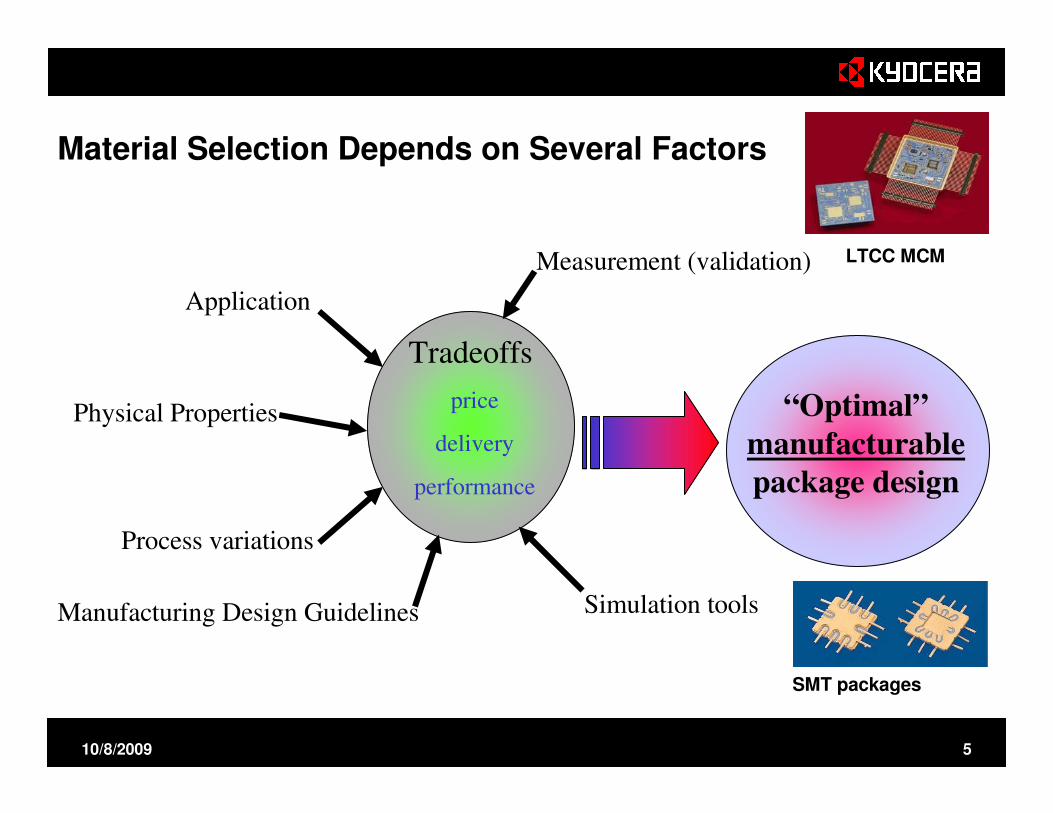
Material Selection Depends on Several Factors
“Optimal”
manufacturable package design
Application
Physical Properties
Process variations
Tradeoffs
price
delivery
performance
Manufacturing Design Guidelines Simulation tools
Measurement (validation)
SMT packages
LTCC MCM

10/8/2009 6
Cost is function of Design, Materials and Manufacturing
Material
Design rules
Cost
$
Number of vias
Number
of
layers
Tolerances
Schedule
Size
Unique
processes
Tooling
Metals
Plating
Assembly
Simulation & Simulation &
ModelingModeling

10/8/2009 7
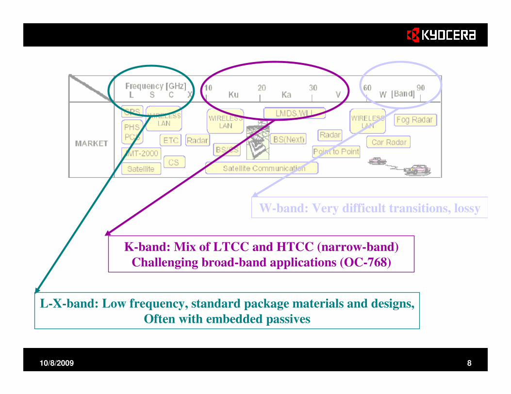
Ceramic Packages and Applications
10/8/2009 8
L-X-band: Low frequency, standard package materials and designs,
Often with embedded passives
K-band: Mix of LTCC and HTCC (narrow-band)
Challenging broad-band applications (OC-768)
W-band: Very difficult transitions, lossy

10/8/2009 9
N2 -Fired Ni plating - Not required
for air-fired LTCC
LTCC Process Flow is similar to HTCC, But Processes and Materials Vary
10/8/2009 10
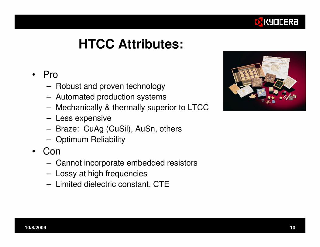
HTCC Attributes:
• Pro– Robust and proven technology
– Automated production systems
– Mechanically & thermally superior to LTCC
– Less expensive
– Braze: CuAg (CuSil), AuSn, others
– Optimum Reliability
• Con– Cannot incorporate embedded resistors
– Lossy at high frequencies
– Limited dielectric constant, CTE

10/8/2009 11
Aluminum Nitride
Frequency (MHz)
tan
δ (
×1
0-4
) AN75W
AN242
250
200
150
100
50
01 10 100 1000 10000100000
0000
20202020
40404040
60606060
80808080
100100100100
120120120120
140140140140
0000 1111 2222 3333 4444 5555Time (sec)Time (sec)Time (sec)Time (sec)
Al2O3Al2O3Al2O3Al2O3
AN75WAN75WAN75WAN75W
AN242AN242AN242AN242
PKG:50mmSQ.CHIP:12.7mmSQ.Power:ca.25W
Junction Temperature (
Junction Temperature (
Junction Temperature (
Junction Temperature (℃℃ ℃℃)) ))
Piezoelectricity Thermal Conductivity-AlN vs. Al2O3

10/8/2009 12
Commercial Suppliers of LTCC Tape
– Dupont 951, 943, 9K7• Easier to process and fire
• Tight shrinkage tolerances
• Electrical performance similar to 92% Al2O3
– Ferro A6M
• Higher variation in shrinkage during firing.
• Lower loss, easier to design high frequency devices (>10 GHz)
• More difficult green processing
– Heraeus Heralock
• Controlled shrinkage
• Less-commonly used

10/8/2009 13
Cu-based LTCC Materials
• Kyocera-developed
• Custom formulations to meet specific applications
– Dielectric constant
– Thermal coefficient of expansion
– Flexural strength
• Nitrogen-fired, Ni-Au plating
• Non-brazeable
• Metal adhesion may be weak
• Excellent for filter designs
• Low insertion loss

10/8/2009 14
Pa
ste
Co
st
($/g
)
$46.00
$3.00
$0.70
$0.12
Du
Po
nt
951
Ky
oce
ra
Du
Po
nt
951
HT
CC
Metallization Cost Drives Package Price
Precious Metal Price not Market Driven
323% increase since 2001

10/8/2009 15
HTCC – LTCC Cost Comparison
LTCC is Performance-based Material
Proper Design in HTCC can achieve necessary performance objectives.
LT
CC
A
u
LT
CC
A
g
LT
CC
Cu
HT
CC
HT
CC
Average Volume Package
Price (Relative Scale)7
6
5
4
3
2
1

10/8/2009 16
Insertion Loss (Au Conductors on Ferro LTCC)Left: Simulating insertion loss with different surface roughnesses and comparing them with measurement data.
Right: Actual surface roughness observation with varied manufacturing process conditions.
Surface
Ink (Gold)
Ceramic

10/8/2009 17
LTCC has Better Performance with Thinner Substrates / Longer Conductor Paths at High Frequencies.How to read this graph: In the region right of the red curve the IL of A473 is more than 0.05 dB inferior to that of A6M for a microstrip line with L= 200
mils. The red curve may also represent 0.25 dB delta per inch. Similarly, the pink line for 0.50 dB delta per inch and the blue line for 1 dB delta per inch.Example: When a 15-mil thick substrate is used for 50-ohm system, A6M material should be 0.25 dB/inch better in IL than A473 at about 9.5 GHz.
50 ohm microstrip; .05 dB IL difference curve
0
2
4
6
8
10
12
14
16
18
20
0 10 20 30 40 50
Frequency (GHz)
su
bstr
ate
heig
ht (m
il)
.05 dB delta curve; L=50 mils
.05 dB delta curve; L=100 mils
.05 dB delta curve; L=200 mils
Insertion Loss Comparison (Simulation):
increasing delta IL
HTCC (Al2O3/W) vs. A6M
(LTCC/Au)
10/8/2009 18
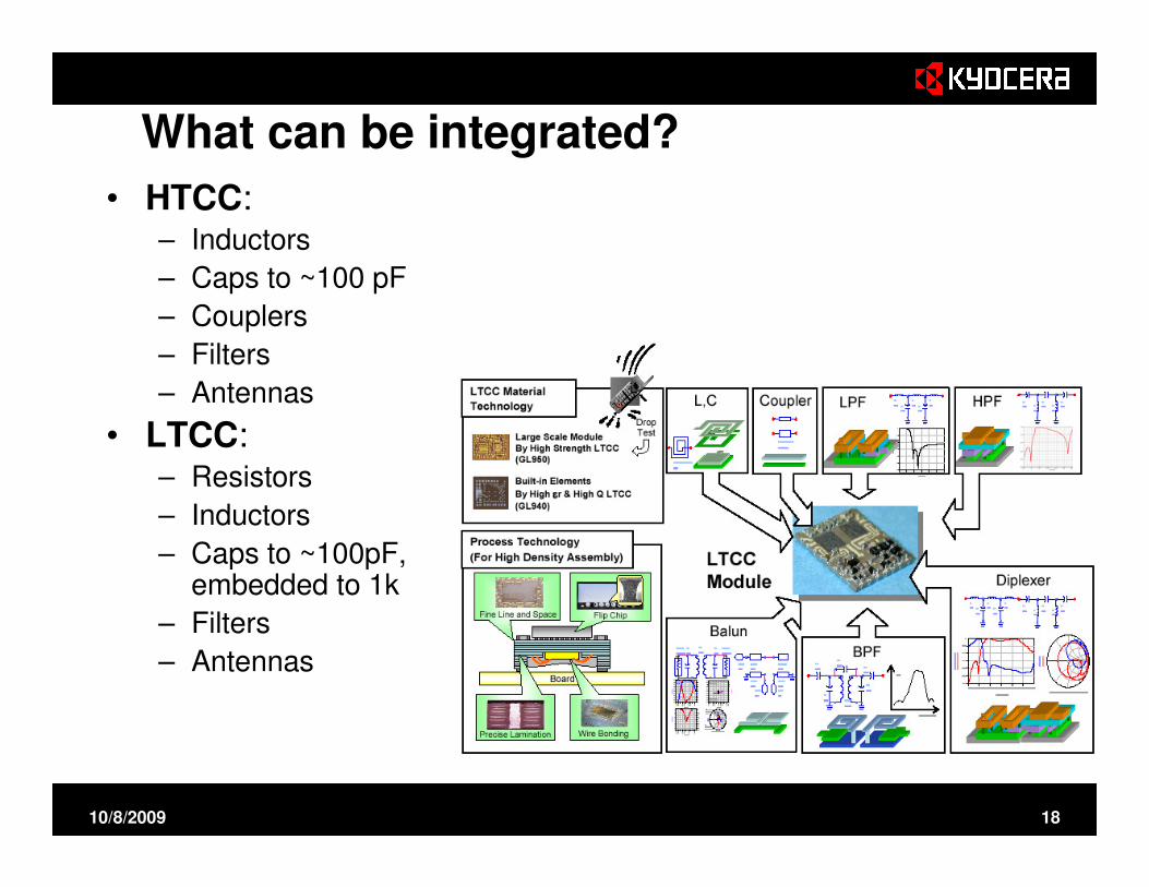
What can be integrated?
• HTCC:– Inductors
– Caps to ~100 pF
– Couplers
– Filters
– Antennas
• LTCC:– Resistors
– Inductors
– Caps to ~100pF, embedded to 1k
– Filters
– Antennas

10/8/2009 19
Multilayer HTCC CapacitorsPrediction vs Results
• Al2O3 ceramic with W metallization
• Cross-sectioned to validate methodology

10/8/2009 20
HF Packages Require Electrical Modeling, Simulation Tools…
� Electrical Modeling, Simulation
– Frequency Domain:
� HFSS
• Ansoft Optimetrics
• Q3D Extractor
• Ansoft Designer
– Time Domain
� CST Microwave Studio
� Full-Wave SPICE – Ansoft
– Sigrity Speed2000 Power SI
– Eagleware – Filter Synthesis
– 2D
� Tx Line
� TLINE
� UIUC2D (stratified layers, finite ground planes)
Simulation
-45
-40
-35
-30
-25
-20
-15
-10
-5
0
0 5 10 15 20 25 30
Frequency (GHz)
Re
turn
Lo
ss
(d
B)
S11-Ansoft
HFSS uses Maxwell’s equations: package model is meshed, and characterized in the frequency domain
Connectors for High Frequency Applications
10/8/2009 21
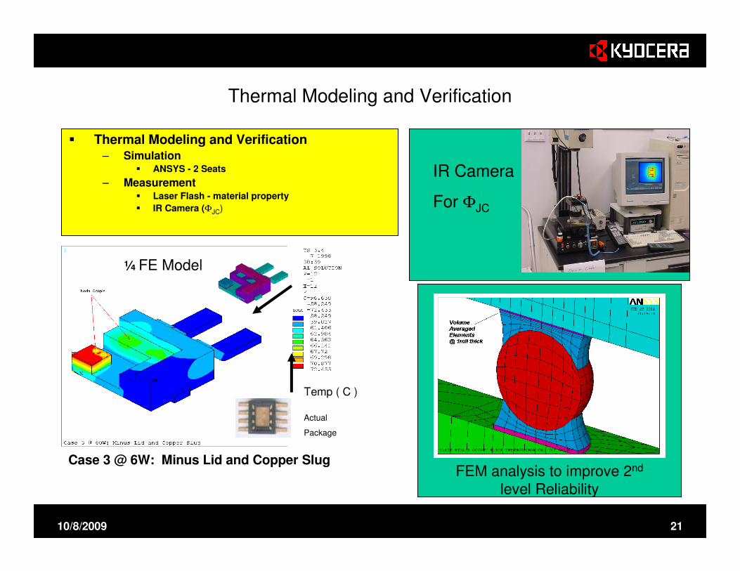
Thermal Modeling and Verification
� Thermal Modeling and Verification– Simulation
� ANSYS - 2 Seats
– Measurement� Laser Flash - material property
� IR Camera (ΦJC)
IR Camera
For ΦJC
Case 3 @ 6W: Minus Lid and Copper Slug
¼ FE Model
Temp ( C )
Actual
Package
FEM analysis to improve 2nd
level Reliability

10/8/2009 22
Material Characterization Capability is Critical for Failure Analysis
� Material Characterization & Failure Analysis Typical Tools:
– Instron
– Phillips ESEM XL30 - SEM 30x 100Kx
– Dilatometer
– X-ray diffraction
– DTA / TGA
– Olympus AX70 - Optical 10x to 1500x microscope
– Sonoscan CSAM300 - Ultrasonic 1x to 10xImage of Silver Dendrite
EDAX X-ray Spectra and MappingSEM

10/8/2009 23
T/R Modules (Transmit-Receive)
• High-Power Microwave
• Phased-Array Radar
• Coaxial Connector
• Compartments provide EM shielding between subcomponents

10/8/2009 24
Other High Reliability Programs
JSFJSF
Global HawkGlobal Hawk
F22F22
Stealth ShipsStealth Ships
AegisAegis
Ground RadarGround Radar

10/8/2009 25
RF Interconnect Design Strategy using Full-wave tools: Ansoft HFSS or CST MWS
Methodology
• Divide RF routing into a series of independent transitions.
– Board to package
– Internal to package
– Package to die
• Identify materials / design options
• Use HFSS or CST to model and optimize each transition
– Break large transitions into sub-models, solve, and optimize.
– Assemble sub-models and solve the entire RF path.
General approach• Short RF transitions.• Arrange vias and ground to inhibit RF reflections.• Re-arrange and shrink cavities to inhibit resonance.• Use coplanar structures for better isolation.• Employ appropriate design rules.
Tuning
Preliminary
Transition
Solid Model
Data Transfer
Simulation
10/8/2009 26
Example: Astrium TR module
The ENVISTAT ASAR Instrument Verification and Characterization, R. Torres, et al
Customer granted permission to
show slides of this design

10/8/2009 27
Original T/R Module
Discrete RF Packages, 1990’s

10/8/2009 28
Conceptual Sketch Started the Simulation Process

10/8/2009 29
Initial Physical Design…
…RF Transitions Defined

10/8/2009 30
Astrium X-band module
Cinch interface + GPPO connectors7 packaged dies on bottom
Self calibration circuitPolarized transmission vertical and horizontal
BGA-packaged ASIC
Antenna tile: 24 TR modules per tile
10/8/2009 31
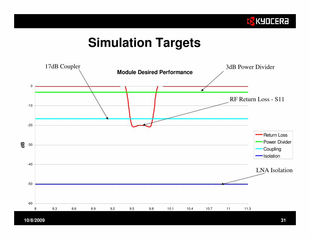
Simulation Targets
Module Desired Performance
-60
-50
-40
-30
-20
-10
0
8 8.3 8.6 8.9 9.2 9.5 9.8 10.1 10.4 10.7 11 11.3
Frequency GHz
dB
Return Loss
Power Divider
Coupling
Isolation
3dB Power Divider17dB Coupler
LNA Isolation
RF Return Loss - S11

10/8/2009 32
Details: 11 individual design challenges
10. GPPO to Long Stripline
7&8. Calibration to GPPO
6. 3dB coupled line
5. Output to Cinch connector short and long versions4. 3dB coupled line
3. Polarization switches to Circulators
2. PA output
1. PA in
9. -16.5dB coupler calibration line
11. Overall combined model

10/8/2009 33
Details of one transition

10/8/2009 34
11 Port Model Results
LNA Isolation
Input/Output S11
3 dB Power Divider 17 dB Coupler

10/8/2009 35
Putting it all together….
24 modules/tile, 28 tiles/satellite
T/R module
Tile Control UnitPower Supply
Units1651

10/8/2009 36
Electrical
(RF loss)
Mechanical
(Braze joint
reliability)
Thermal Material cost Resistor
Alumina B A C B No
Med-loss LTCC B B D C Yes
Low-loss LTCC A D D D Yes
Aluminum nitride C B A C No
BeO (post-fire) C A A+ B No
The Best Ceramic Solution?
It depends

10/8/2009 37
1
10
100
1000
10000
100000
1000000
Wid
e -
X X
Wid
e -
X Ku
Wid
e -
Ku
Ka
Ku L S
Wid
e -
S
Wid
e -
X X
Ku
Ka
- N
arr
ow S
Wid
e -
X Ku
Ka
Ka
Wid
e -
X Ku Q W
Package Design plays a Significant roll in Meeting Required Specifications at High Frequencies
HTCC LTCC
AlNAl2O3
A - 440
Al2O3
A - 473
DuPont951
FerroA6M
Packag
es
Updated - June 2009

10/8/2009 38
High Volume T/R Module
Reprinted from Military and
Aerospace Electronics, May 2003.
10/8/2009 39
Conclusions
• Materials choice should be based on:
– Performance Requirements
– Manufacturability
– Cost Objectives
• No “best” material for all applications
• Simulation and validation are critical

10/8/2009 40
Kyocera Sales ContactsEastern Region
Boston: Bob Palumbo 508-651-8161New Jersey: Antonio Pagkalinawan 732-563-4379
Central RegionAustin, TX Ross Linker 512-809-0195Dallas, TX Lawrence Santos 972-234-2408Phoenix, AZ Katie Hanken 602-315-6664
Western RegionPortland, OR Scott Tse 503-526-6962San Jose, CA Scott Tse 510-257-0150
San Diego, CA John Hatakeyama 858-576-2764