Embed Size (px)
Citation preview
International Journal of Current Engineering and Technology E-ISSN 2277 – 4106, P-ISSN 2347 – 5161 ©2016 INPRESSCO®, All Rights Reserved Available at http://inpressco.com/category/ijcet
Research Article
574| International Journal of Current Engineering and Technology, Vol.6, No.2 (April 2016)
Material optimization and Modal Analysis of Elevator bucket
Sunil Tukaram Shinde†*, Vidyadhar Sudarshan Dixit†, Masnaji Rajaram Nukulwar† and Shailesh S. Pimpale†
†Mechanical (Design Engineering), Department, SPPU, JSPMs Rajarshi Shahu College of Engineering Tathawade. Pune. India
Accepted 06 April 2016, Available online 11 April 2016, Vol.6, No.2 (April 2016)
Abstract A Bucket Elevator is a material handling equipment. It can elevate variety of bulk materials from light to heavy and from fine to large lumps. It consists of endless chain drive & on which metallic buckets are fixed. Bucket elevators always faces problem during buildup loads. In order to overcome this problem high capacity bucket is to be designed which will carry higher loads. This can achieve by using different materials. As new materials are developed and quality materials become more readily available, then changes in design have been made to adapt to these materials. Different iterations will be carried out to serve the best material. Also, bucket elevators often experience certain vibration while carrying a material. So the modal analysis will be done to find its natural frequency. For this a 3D model of bucket of elevator will be modeled in CATIAV5, meshing will be carried out in HYPERMESH, and ANSYS will be used for post processing. Based on results material optimization will be carried out and through re-iteration best material will be suggested. Results obtained from numerical method will be validated with the experimental results. Keywords: Bucket Elevator, material handling equipment, modal analysis of bucket, material optimization of bucket. Introduction
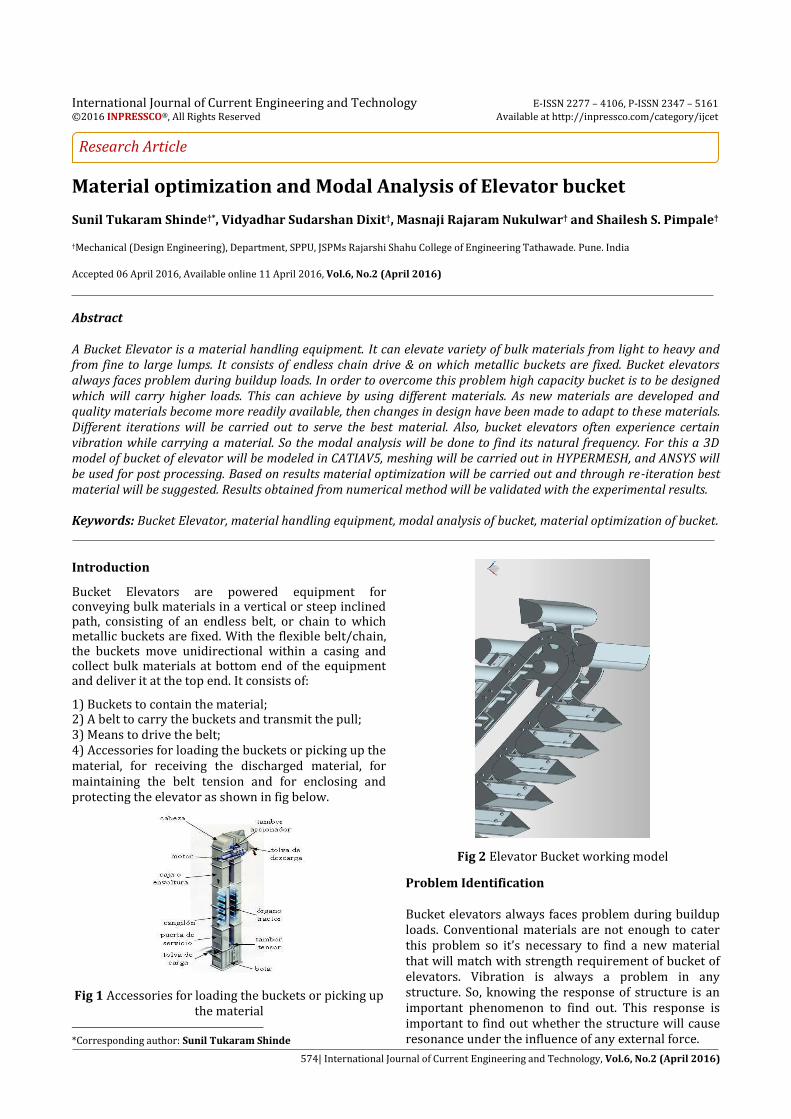
1 Bucket Elevators are powered equipment for conveying bulk materials in a vertical or steep inclined path, consisting of an endless belt, or chain to which metallic buckets are fixed. With the flexible belt/chain, the buckets move unidirectional within a casing and collect bulk materials at bottom end of the equipment and deliver it at the top end. It consists of:
1) Buckets to contain the material; 2) A belt to carry the buckets and transmit the pull; 3) Means to drive the belt; 4) Accessories for loading the buckets or picking up the material, for receiving the discharged material, for maintaining the belt tension and for enclosing and protecting the elevator as shown in fig below.
Fig 1 Accessories for loading the buckets or picking up the material
*Corresponding author: Sunil Tukaram Shinde
Fig 2 Elevator Bucket working model
Problem Identification Bucket elevators always faces problem during buildup loads. Conventional materials are not enough to cater this problem so it’s necessary to find a new material that will match with strength requirement of bucket of elevators. Vibration is always a problem in any structure. So, knowing the response of structure is an important phenomenon to find out. This response is important to find out whether the structure will cause resonance under the influence of any external force.
Sunil Tukaram Shinde et al Material optimization and Modal Analysis of Elevator bucket
575| International Journal of Current Engineering and Technology, Vol.6, No.2 (April 2016)
Literature Review
Snehal Patel, Sumant Patel, Jigar Patel, A Review on Design and Analysis of Bucket Elevator, International Journal of Engineering Research and Applications ISSN: 2248-9622 Vol. 2, Issue 5, September- October 2012, pp.018-022. This paper deals with the design and analysis of different parts of elevator for conveying different types of materials. The modeling of bucket elevator done using solid modeling software and analyzed using conventional finite element software (Ansys) and stresses and deflections are obtained. This study also shows that the negative influences of support of the shaft reflected through the increase in the stress concentration and occurrence of the initial crack are the main causes of the shaft fracture which is occurred at the keyway of the shaft and zone of contact between shaft and gearbox. N. Yashaswini, Raju. B and A. Purushottham, design
and optimization of bucket elevator through finite
element analysis, International Journal of Mechanical
Engineering Volume 2, Issue 9, September 2014 ISSN
2321-6441.
Authors have designed a bucket elevator and
analyzed it for conveying granular materials to the
height of 15m at the rate of 10 tones/hour output. This
paper gives basic design calculations for the
development of the bucket elevator, in 3D environment
of NX software. Static and vibration analysis carried
out on the bucket elevator in order to need the
required output from 10 tonnes/hr-20 tonnes/hr. This
paper also gives the dynamic behavior of the bucket
and gear shaft assembly. The results obtained from the
analysis study critically examine the modification of
design parameters.
Snehal Patel, Sumant Patel, Jigar Patel, Productivity
Improvement of Bucket Elevator by Modified Design,
International Journal of Emerging Technology and
Advanced ISSN 2250-2459, Volume 3, Issue 1, January
2013.
This work deals with the design and analysis of
elevator for conveying granular materials at 2
tonnes/hour output and lifting height 12m. Modeling of
different components of bucket elevator has been done
using 3d Solid Modeling software based upon the
dimensions obtained from analytical design. The new
modified design of the bucket elevator is proposed and
validated using CAE tools which are well within the
safe limit. Bucket elevator mainly fails due to breaking
occurs at the inner edge of the pulley, it consider as
fretting corrosion. Hence new material EN24 has been
suggested for the shaft. From the analysis, it can be
seen that for modified design has higher FOS than
existing design.
Hemlata H. Mulik, Bhaskar D. Gaikwad, Design of Sugar Bucket Elevator and Roller Conveyor Chain for
20 Tonnes per Hour Capacity, International Journal of Engineering Trends and Technology, Volume 20 Number 1 – Feb 2015. In this paper the different components of roller
conveyor chains are designed for sugar bucket elevator
used in sugar industries for 20 tonnes per hour
capacity and the loading conditions are described. The
advantages of chain drive as compared with other
drives are discussed. The chain wear mechanisms
found in literature are listed. Abrasive and adhesive
wear between pin, bushing, and roller are also
discussed.
F.J.C. Rademacher, Non-Spill Discharge Characteristics of Bucket Elevators, Elsevier Sequoia S.A., Lausanne. One of the well-known disadvantages of a simple
type bucket elevator is still the backflow or spill. The
accordingly lower capacity and increased power
consumption are not always the worst consequences,
provided that the boot does not become too full. With
the considerable heights of modem bucket elevators,
up to 225 feet and over, serious damaging of the
conveyed material, an intensified noise level and
increased wear can be far more inconvenient. The
discharge of the buckets has been recognized as an
extremely complicated phenomenon which strictly
speaking cannot be analyzed theoretically. This holds
even more for free-flowing materials. Nevertheless, an
analytical approximation has been worked out for the
relatively simple case of cylindrical buckets filled with
cohesive bulk material, to start with. With the
developed approximate theory a spill-free combination
of the relevant parameters has been found.
J.L.P_erez-Aparicio, R. Bravo, J.J.G omez-Hern andez,
Optimal numerical design of bucket elevators using
discontinuous deformation analysis, Department of
Continuum. Mechanics and Theory of Structures,
Universitat Polit_ecnica de Val_encia, Valencia, Spain.
In this paper, a study of discharge of elevator bucket is
done. Bucket elevators are efficient machines to
transport granular materials in industrial and civil
engineering applications. These materials are
composed of hundreds, thousands or even more
particles, the global Behavior of which is defined by
contact interactions. The first attempts to analyze the
transportation of granular materials were treated.
Given the internal discontinuity nature of granular
media, it is reasonable to use numerical methods to
model their behavior, such as Discontinuous
Deformation Analysis (DDA) a member of the Discrete
Element Method family that started to be used in the
90's to analyze similar problems.
Design Design is based on IS standards.
Sunil Tukaram Shinde et al Material optimization and Modal Analysis of Elevator bucket
576| International Journal of Current Engineering and Technology, Vol.6, No.2 (April 2016)
Assumptions The following factors are considered during design Material for lifting: Steel shot Average bulk density: = 4004.6 kg/m3 Applications: foundries, steel shot is used for blast cleaning - removing of contaminant (oxide layer and sand), steel mills, forging shops, rolling mills, polishing, shot peening. Calculation Selection of Elevator: The selection of the type of elevator is governed by the characteristics of the material handled, whether lumpy or fine, abrasive or non-abrasive and whether material will stand centrifugal discharge or it needs to be handled more slowly to avoid breakage. 1. Centrifugal Discharge Elevators -This is the most commonly used type with buckets type, mounted on belt or chain, spaced at intervals to avoid interference in loading and discharge. This is mostly vertical and handles practically and free flowing fine or small lump material such as grain, coal, sand, clay, sugar or dry chemicals. 2. Continuous Discharge Elevators - This is the elevator, often used for handling larger lumps and material that may be difficult to handle by centrifugal discharge elevators. Buckets are so shaped and mounted on chain or belt that, as they pass over the head wheel, the flanged end of the preceding bucket acts as a chute to lower material to the elevated discharge spout. The slow speed and gentle method of loading and discharging minimize breakage of fragile materials and also makes this a satisfactory type for pulverized or fluffy materials, such as lime, cement, or certain dry chemicals. Continuous buckets are not recommended to be filled in by digging and must be filled in by a loading leg. This type of elevator can be operated vertically or inclined; when inclined, special guides are furnished for carrying rim and wider casing provided to allow for sag in return run. 3. Positive Discharge Elevators - This is similar to centrifugal discharge elevator except that spaced buckets are end-mounted between two strands of chain and are snubbed back under the head sprockets to invert buckets and gain complete discharge. Bucket speed is slower and this type is especially suited to handle light, aerated, dusty, and sticky materials that will not discharge without difficulty in centrifugal discharge elevator. The slight impact of chains skating on snubbed sprockets also helps to free materials, such as wet coal with tendency to stick to buckets.
Type of elevator is selected from below table
Selection of the type of bucket shall be done on the basis of type of elevator that is centrifugal or continuous type according to recommendations given ahead
Table1: selection of elevator (Ref: IS 7167.1974, pg 9) Depending on our application Continuous discharge
type of elevator is used
Type of Elevator Type of bucket
Recommended application
Centrifugal and positive
discharge
A1 For powdered and free flowing material
A2 For cement, coal, sand, gravel, stone, pulp, ores
chemicals, fertilizers and similar other materials
A3
For wet, stringly materials likely to stick in buckets.
Also used for handling stones and ores and other coarsely broken material
on inclined elevators
A4 Used for sugar, clay, salt,
pulverized wet ores which tend to pack in the buckets
Continuous discharge
B1 Used for pulverized and
sluggish material that stick or pack in buckets and on
inclined elevators B2 Used for average materials
for vertical elevators
B3 Used when extra capacity
and large lumps are to be
handled
B4 Used on inlined bucket elevators not over 70°C
inclination with horizontal
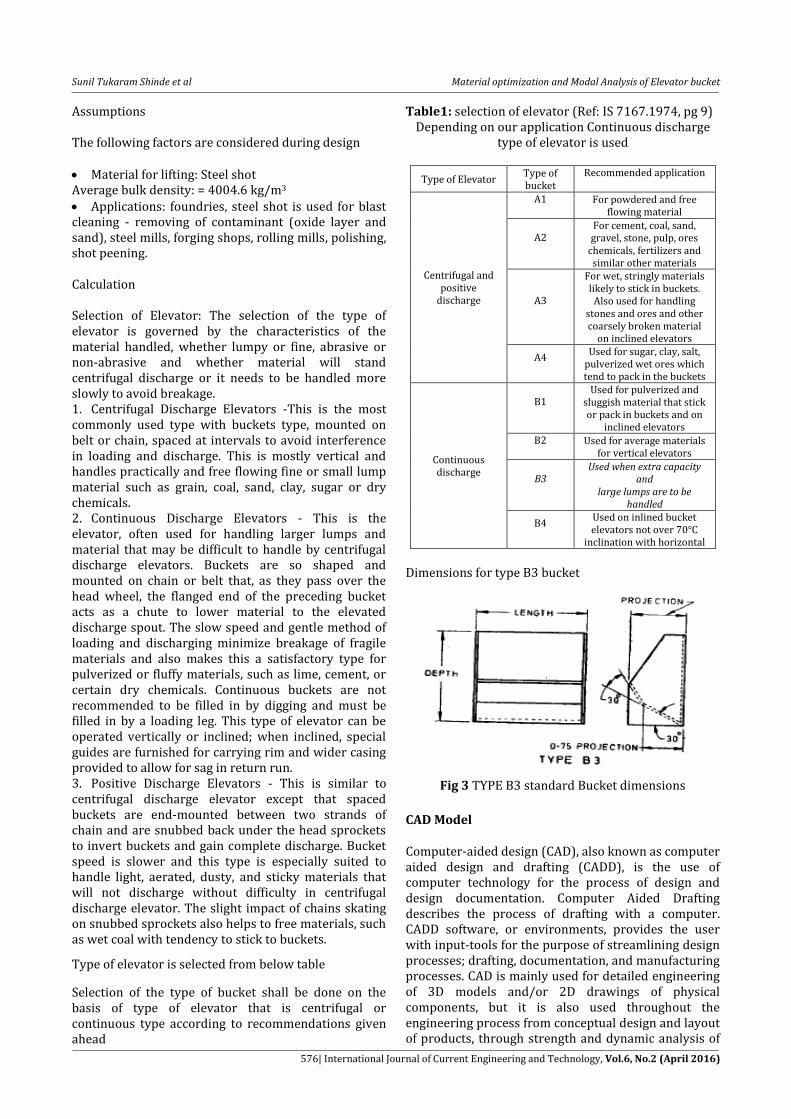
Dimensions for type B3 bucket
Fig 3 TYPE B3 standard Bucket dimensions
CAD Model
Computer-aided design (CAD), also known as computer aided design and drafting (CADD), is the use of computer technology for the process of design and design documentation. Computer Aided Drafting describes the process of drafting with a computer. CADD software, or environments, provides the user with input-tools for the purpose of streamlining design processes; drafting, documentation, and manufacturing processes. CAD is mainly used for detailed engineering of 3D models and/or 2D drawings of physical components, but it is also used throughout the engineering process from conceptual design and layout of products, through strength and dynamic analysis of
Sunil Tukaram Shinde et al Material optimization and Modal Analysis of Elevator bucket
577| International Journal of Current Engineering and Technology, Vol.6, No.2 (April 2016)
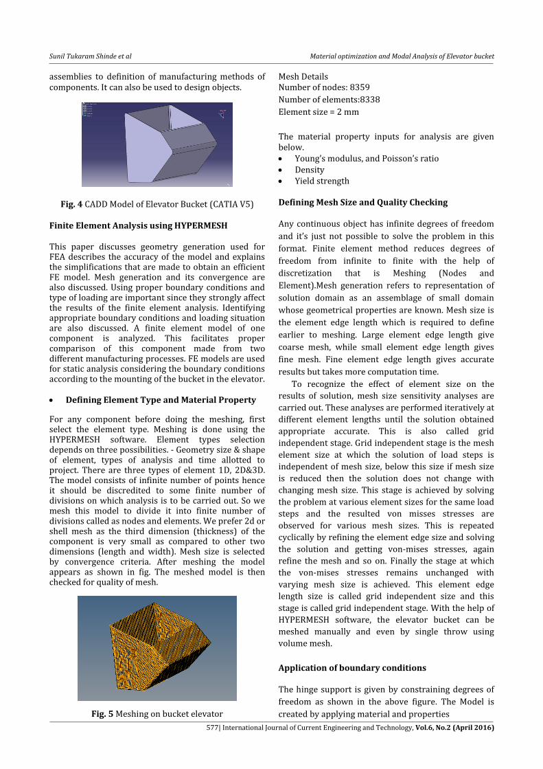
assemblies to definition of manufacturing methods of components. It can also be used to design objects.
Fig. 4 CADD Model of Elevator Bucket (CATIA V5)
Finite Element Analysis using HYPERMESH This paper discusses geometry generation used for FEA describes the accuracy of the model and explains the simplifications that are made to obtain an efficient FE model. Mesh generation and its convergence are also discussed. Using proper boundary conditions and type of loading are important since they strongly affect the results of the finite element analysis. Identifying appropriate boundary conditions and loading situation are also discussed. A finite element model of one component is analyzed. This facilitates proper comparison of this component made from two different manufacturing processes. FE models are used for static analysis considering the boundary conditions according to the mounting of the bucket in the elevator. Defining Element Type and Material Property
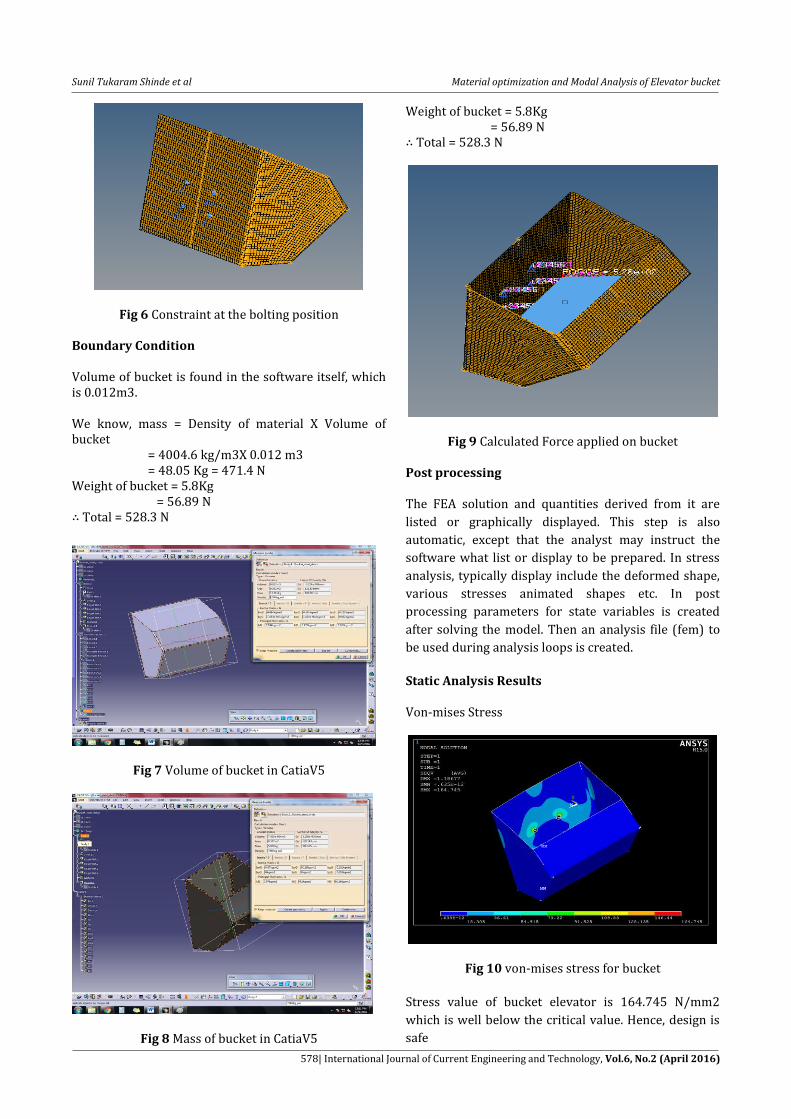
For any component before doing the meshing, first select the element type. Meshing is done using the HYPERMESH software. Element types selection depends on three possibilities. - Geometry size & shape of element, types of analysis and time allotted to project. There are three types of element 1D, 2D&3D. The model consists of infinite number of points hence it should be discredited to some finite number of divisions on which analysis is to be carried out. So we mesh this model to divide it into finite number of divisions called as nodes and elements. We prefer 2d or shell mesh as the third dimension (thickness) of the component is very small as compared to other two dimensions (length and width). Mesh size is selected by convergence criteria. After meshing the model appears as shown in fig. The meshed model is then checked for quality of mesh.
Fig. 5 Meshing on bucket elevator
Mesh Details Number of nodes: 8359
Number of elements:8338
Element size = 2 mm
The material property inputs for analysis are given below. Young’s modulus, and Poisson’s ratio Density Yield strength Defining Mesh Size and Quality Checking Any continuous object has infinite degrees of freedom
and it’s just not possible to solve the problem in this
format. Finite element method reduces degrees of
freedom from infinite to finite with the help of
discretization that is Meshing (Nodes and
Element).Mesh generation refers to representation of
solution domain as an assemblage of small domain
whose geometrical properties are known. Mesh size is
the element edge length which is required to define
earlier to meshing. Large element edge length give
coarse mesh, while small element edge length gives
fine mesh. Fine element edge length gives accurate
results but takes more computation time.
To recognize the effect of element size on the
results of solution, mesh size sensitivity analyses are
carried out. These analyses are performed iteratively at
different element lengths until the solution obtained
appropriate accurate. This is also called grid
independent stage. Grid independent stage is the mesh
element size at which the solution of load steps is
independent of mesh size, below this size if mesh size
is reduced then the solution does not change with
changing mesh size. This stage is achieved by solving
the problem at various element sizes for the same load
steps and the resulted von misses stresses are
observed for various mesh sizes. This is repeated
cyclically by refining the element edge size and solving
the solution and getting von-mises stresses, again
refine the mesh and so on. Finally the stage at which
the von-mises stresses remains unchanged with
varying mesh size is achieved. This element edge
length size is called grid independent size and this
stage is called grid independent stage. With the help of
HYPERMESH software, the elevator bucket can be
meshed manually and even by single throw using
volume mesh.
Application of boundary conditions The hinge support is given by constraining degrees of
freedom as shown in the above figure. The Model is
created by applying material and properties
Sunil Tukaram Shinde et al Material optimization and Modal Analysis of Elevator bucket
578| International Journal of Current Engineering and Technology, Vol.6, No.2 (April 2016)
Fig 6 Constraint at the bolting position Boundary Condition Volume of bucket is found in the software itself, which is 0.012m3. We know, mass = Density of material X Volume of bucket = 4004.6 kg/m3X 0.012 m3 = 48.05 Kg = 471.4 N Weight of bucket = 5.8Kg = 56.89 N Total = 528.3 N
Fig 7 Volume of bucket in CatiaV5
Fig 8 Mass of bucket in CatiaV5
Weight of bucket = 5.8Kg = 56.89 N Total = 528.3 N
Fig 9 Calculated Force applied on bucket Post processing The FEA solution and quantities derived from it are
listed or graphically displayed. This step is also
automatic, except that the analyst may instruct the
software what list or display to be prepared. In stress
analysis, typically display include the deformed shape,
various stresses animated shapes etc. In post
processing parameters for state variables is created
after solving the model. Then an analysis file (fem) to
be used during analysis loops is created.
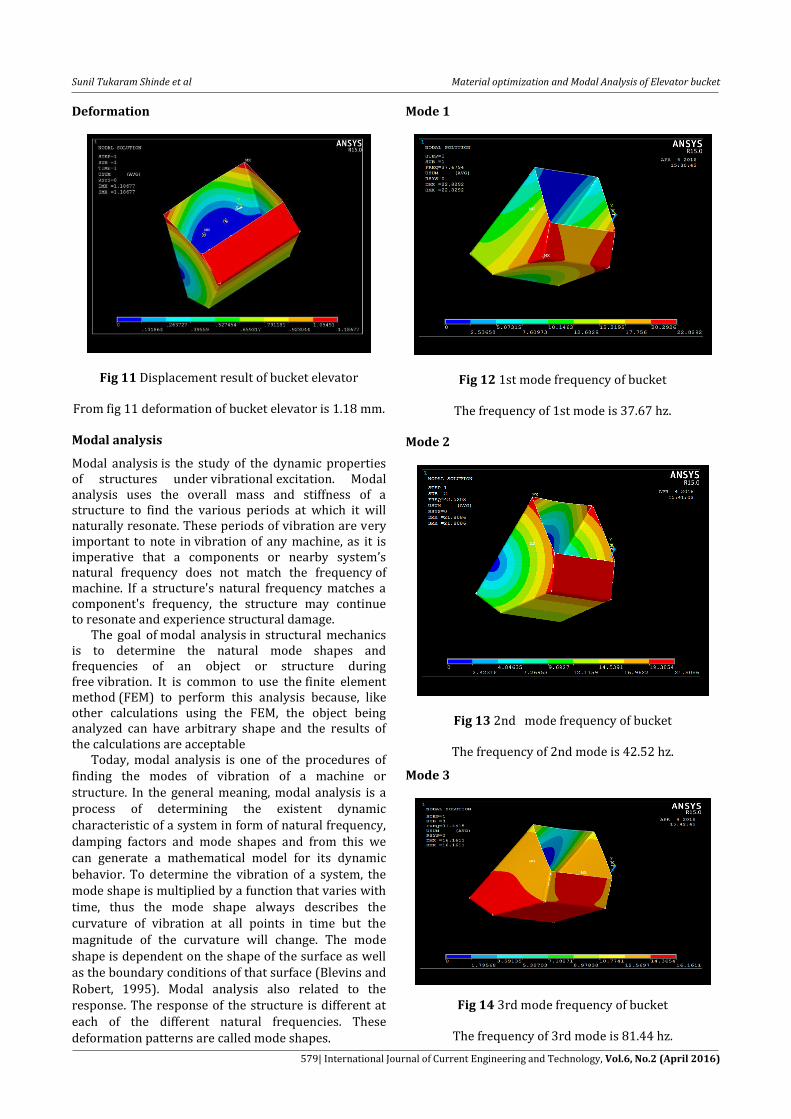
Static Analysis Results Von-mises Stress
Fig 10 von-mises stress for bucket
Stress value of bucket elevator is 164.745 N/mm2
which is well below the critical value. Hence, design is
safe
Sunil Tukaram Shinde et al Material optimization and Modal Analysis of Elevator bucket
579| International Journal of Current Engineering and Technology, Vol.6, No.2 (April 2016)
Deformation
Fig 11 Displacement result of bucket elevator From fig 11 deformation of bucket elevator is 1.18 mm. Modal analysis
Modal analysis is the study of the dynamic properties of structures under vibrational excitation. Modal analysis uses the overall mass and stiffness of a structure to find the various periods at which it will naturally resonate. These periods of vibration are very important to note in vibration of any machine, as it is imperative that a components or nearby system’s natural frequency does not match the frequency of machine. If a structure's natural frequency matches a component's frequency, the structure may continue to resonate and experience structural damage. The goal of modal analysis in structural mechanics is to determine the natural mode shapes and frequencies of an object or structure during free vibration. It is common to use the finite element method (FEM) to perform this analysis because, like other calculations using the FEM, the object being analyzed can have arbitrary shape and the results of the calculations are acceptable Today, modal analysis is one of the procedures of finding the modes of vibration of a machine or structure. In the general meaning, modal analysis is a process of determining the existent dynamic characteristic of a system in form of natural frequency, damping factors and mode shapes and from this we can generate a mathematical model for its dynamic behavior. To determine the vibration of a system, the mode shape is multiplied by a function that varies with time, thus the mode shape always describes the curvature of vibration at all points in time but the magnitude of the curvature will change. The mode shape is dependent on the shape of the surface as well as the boundary conditions of that surface (Blevins and Robert, 1995). Modal analysis also related to the response. The response of the structure is different at each of the different natural frequencies. These deformation patterns are called mode shapes.
Mode 1
Fig 12 1st mode frequency of bucket
The frequency of 1st mode is 37.67 hz.
Mode 2
Fig 13 2nd mode frequency of bucket
The frequency of 2nd mode is 42.52 hz.
Mode 3
Fig 14 3rd mode frequency of bucket
The frequency of 3rd mode is 81.44 hz.
Sunil Tukaram Shinde et al Material optimization and Modal Analysis of Elevator bucket
580| International Journal of Current Engineering and Technology, Vol.6, No.2 (April 2016)
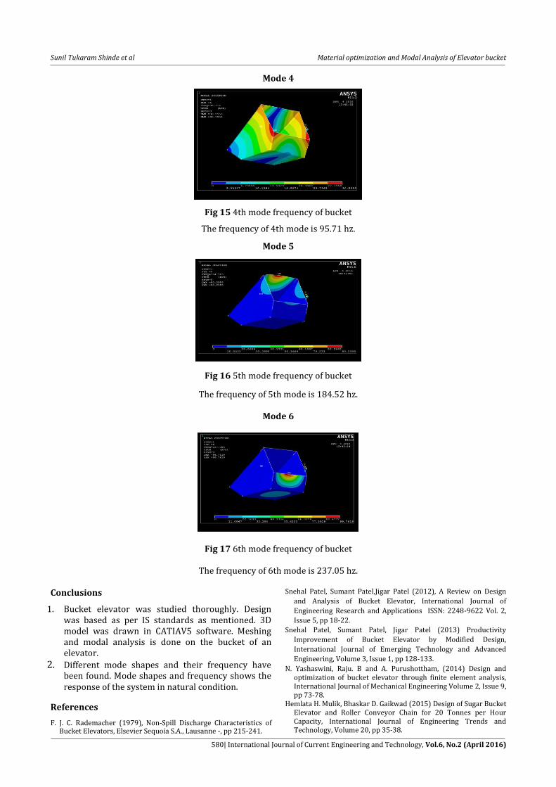
Mode 4
Fig 15 4th mode frequency of bucket
The frequency of 4th mode is 95.71 hz.
Mode 5
Fig 16 5th mode frequency of bucket
The frequency of 5th mode is 184.52 hz.
Mode 6
Fig 17 6th mode frequency of bucket
The frequency of 6th mode is 237.05 hz.
Conclusions
1. Bucket elevator was studied thoroughly. Design was based as per IS standards as mentioned. 3D model was drawn in CATIAV5 software. Meshing and modal analysis is done on the bucket of an elevator.
2. Different mode shapes and their frequency have been found. Mode shapes and frequency shows the response of the system in natural condition.
References
F. J. C. Rademacher (1979), Non-Spill Discharge Characteristics of Bucket Elevators, Elsevier Sequoia S.A., Lausanne -, pp 215-241.
Snehal Patel, Sumant Patel,Jigar Patel (2012), A Review on Design
and Analysis of Bucket Elevator, International Journal of
Engineering Research and Applications ISSN: 2248-9622 Vol. 2,
Issue 5, pp 18-22.
Snehal Patel, Sumant Patel, Jigar Patel (2013) Productivity
Improvement of Bucket Elevator by Modified Design,
International Journal of Emerging Technology and Advanced
Engineering, Volume 3, Issue 1, pp 128-133.
N. Yashaswini, Raju. B and A. Purushottham, (2014) Design and optimization of bucket elevator through finite element analysis, International Journal of Mechanical Engineering Volume 2, Issue 9, pp 73-78.
Hemlata H. Mulik, Bhaskar D. Gaikwad (2015) Design of Sugar Bucket Elevator and Roller Conveyor Chain for 20 Tonnes per Hour Capacity, International Journal of Engineering Trends and Technology, Volume 20, pp 35-38.

![Finding the m best solution using search. Optimization algorithms for Bayesian networks developed in our group ● Bucket Elimination [Dechter 1996] ● Bucket](https://img.pdfslide.us/doc/110x75/56649d2f5503460f94a06d9a/finding-the-m-best-solution-using-search-optimization-algorithms-for-bayesian.jpg)