Embed Size (px)
Citation preview

Printed on 14 September, 2012
Manual # 99904591
Material Handling Crane Operation & Safety
Revision Date 20180530
IOWA MOLD TOOLING CO., INC. PO Box 189
Garner, IA 50438 Tel: 641-923-3711 FAX: 641-923-2424
Website: http://www.imt.com
Copyright © 2011 Iowa Mold Tooling Co., Inc. All rights reserved
No part of this publication may be reproduced, stored in a retrieval system, or transmitted in any form or by any means, electronic, mechanical, photocopying, recording or otherwise without the prior written permission of Iowa Mold Tooling Co., Inc.
Iowa Mold Tooling Co., Inc. is an Oshkosh Corporation Company.

i
Contents
Revisions .....................................................................................................................................................iv
Introduction 5
Crane Component Identification...................................................................................................................7 Appropriate Loader Applications .................................................................................................................8
The Operator 11
Operator Qualifications...............................................................................................................................11 Operator Physical Condition.......................................................................................................................12 Operator Conduct........................................................................................................................................12 Knowledge & Abilities Required................................................................................................................13
Crane Operation 15
Operator Responsibilities............................................................................................................................15 Daily Safety Inspections .............................................................................................................................16 Crane Transport ..........................................................................................................................................16 Work Site Planning.....................................................................................................................................17 Material Handling Crane Controls..............................................................................................................19 Engaging the PTO.......................................................................................................................................19 Stabilizers ...................................................................................................................................................20 Hydraulic Swing-up Stabilizer Legs Controlled by Slewing Cylinder Piston Rod.....................................22 Hydraulic Swing-up Stabilizer Legs Controlled by Connecting Rod .........................................................25 Unfolding the Loader..................................................................................................................................27 Unfolding a Z-Loader or Grab-Loader .......................................................................................................28 Electrical Hazards.......................................................................................................................................29 Safely Operating the Crane.........................................................................................................................31 Crane Capacity............................................................................................................................................35 Stowing the Loader.....................................................................................................................................36 Stowing a Z-Loader or Grab-Loader without Top Seat Controls ...............................................................37 Stowing a Z-Loader or Grab-Loader with Top Seat Controls ....................................................................38 Direction Terminology ...............................................................................................................................39
Crane Decals 41
Danger Decals.............................................................................................................................................41 Decal Placement - Material Handling Cranes.............................................................................................42 Danger Decal Figures .................................................................................................................................43 Instructional Decals ....................................................................................................................................46
Hand Signals 49

ii Contents
Component Installation 51
Winch Safety ..............................................................................................................................................51 Winch Mount - Outer Boom.......................................................................................................................52 Winch Mount - Fly-Jib ...............................................................................................................................53 Winch Mount - Inner Boom........................................................................................................................55 Winch Installation on Boom System ..........................................................................................................57 Fly-Jib.........................................................................................................................................................59 Fly-Jib Safety..............................................................................................................................................61
Wire Rope & Hooks 63
Wire Rope Inspection .................................................................................................................................63 Wire Rope Lubrication ...............................................................................................................................64 Wire Rope Inspection & Replacement........................................................................................................64 Wire Rope Slings........................................................................................................................................66 Basic Hitches ..............................................................................................................................................67 Sling Loading..............................................................................................................................................68 Hooks..........................................................................................................................................................68 Methods of Hook Inspection.......................................................................................................................69 Hook Testing ..............................................................................................................................................71
Capacity 73
Crane Capacity & Stability .........................................................................................................................74 Using the Capacity Placard.........................................................................................................................75 Crane Stability ............................................................................................................................................77
Maintenance 81
Crane Maintenance Precautions..................................................................................................................81 Daily Maintenance......................................................................................................................................82 Recommended Oil & Grease ......................................................................................................................83 Grease Points ..............................................................................................................................................84 Greasing - Central Grease Point on Loader Base........................................................................................85 Greasing Push Rods at the Inner and Outer Boom Cylinders .....................................................................87 Greasing Boom System Sliding Surfaces ...................................................................................................88 Bleeding Air from Cylinders ......................................................................................................................88 Repair..........................................................................................................................................................88 Chemical Safety..........................................................................................................................................89
Crane Design 91
Loader Safety Factors .................................................................................................................................91 Hydraulic System Design ...........................................................................................................................92 Load Moment Limitation............................................................................................................................93 Heavy Duty Lifting - HDL .........................................................................................................................94 Hoses and Hydraulic Pipes .........................................................................................................................94

Contents iii
General Reference 95
Inspection Checklist....................................................................................................................................95 Deficiency / Recommendation / Corrective Action Report ......................................................................100 Turntable Bearing Thread Tightening Sequence ......................................................................................102 Turntable Bearing Inspection....................................................................................................................103 Turntable Bearing Tilt Test.......................................................................................................................103 Thread Torque Charts ...............................................................................................................................105

iv Contents
Revisions
DATE LOCATION DESCRIPTION 20120104 THROUGHOUT ECN 11628 - UPDATED STABILIZER WORDING, ELECTROCUTION
HAZARD INFORMATION. 20120914 UPDATED STABILITY TEST.
5
This manual is designed for the loader operator. It is a supplement to the Instruction Manual, Technical Specifications, and Parts Manuals for each loader. It describes how to operate your loader in the safest possible manner, with examples of hazards and methods to avoid dangerous situations. It does not replace any government regulations, safety codes, or insurance carrier requirements. Operators and maintenance and test personnel must read and understand all safety procedures applicable to the equipment in use.
WARNING
READ YOUR MANUAL!! FAILURE TO READ, UNDERSTAND AND FOLLOW ANY SAFETY PROCEDURES APPLICABLE TO YOUR EQUIPMENT MAY RESULT IN EQUIPMENT DAMAGE, SERIOUS INJURY, OR DEATH.
Use caution and common sense while operating and maintaining the crane, and follow all safety procedures and regulations. Treat this equipment with respect and service it regularly. In addition to reading the manual, become familiar with government regulations, hazards, and the specific operation of your crane. Refer to ANSI/ASME B30.22, the standard for Articulating Boom Cranes, for more information on crane design and test criteria. (You may obtain this publication from ASME at www.asme.org.) Crane operators must also be familiar with OSHA 29CFR, Subpart N, Article 1926.550 and CAL-OSHA Title 8, Article 93 (California).
MODIFICATIONS
Modifications to your crane must be performed with IMT approved accessories, parts and optional equipment. If in doubt about the safety, compatibility, or appropriateness of any modifications, contact IMT prior to making those modifications. DO NOT alter or modify any safety device! All safety devices must be inspected, tested and maintained in proper working condition.
Note that decals regarding crane safety and operation are considered safety equipment. They must be maintained just as any other safety device. Decals must be kept clean and legible to the operator, operational personnel, and bystanders as specified in the decal section of this manual. DO NOT remove, disable, or disregard any safety device attached to your crane.
WARRANTY
Warranty of this unit will be void on any part of the unit subjected to misuse due to overloading, abuse, lack of maintenance and unauthorized modifications. No warranty - verbal, written or implied - other than the official, published IMT new machinery and equipment warranty will be valid with this unit.
C H A P T E R 1
Introduction
6 Material Handling Crane Operation & Safety Manual # 99904591
NOTICE TO THE OWNER / USER
If your equipment is involved in a property damage accident, contact your IMT distributor immediately and provide them with the details of the accident and the serial number of the equipment. If an accident involves personal injury, immediately notify your distributor and IMT’s Technical Support at:
IOWA MOLD TOOLING CO., INC. 500 HWY 18 WEST GARNER, IA 50438
641 - 923 - 3711
MANUAL STRUCTURE Throughout this manual, three means are used to draw the attention of personnel. They are NOTEs, CAUTIONs and WARNINGs and are defined as follows:
NOTE
A NOTE is used to either convey additional information or to provide further emphasis for a previous point.
CAUTION
A CAUTION is used when there is the very strong possibility of damage to the equipment or premature equipment failure.
WARNING
A WARNING is used when there is the potential for personal injury or death.
This manual is divided into specific sections in order to keep similar subject matter under one heading. In some cases, a subject may be presented in more than one section of the manual. This redundancy is necessary in order to provide comprehensive information.
Chapter 1 Introduction 7
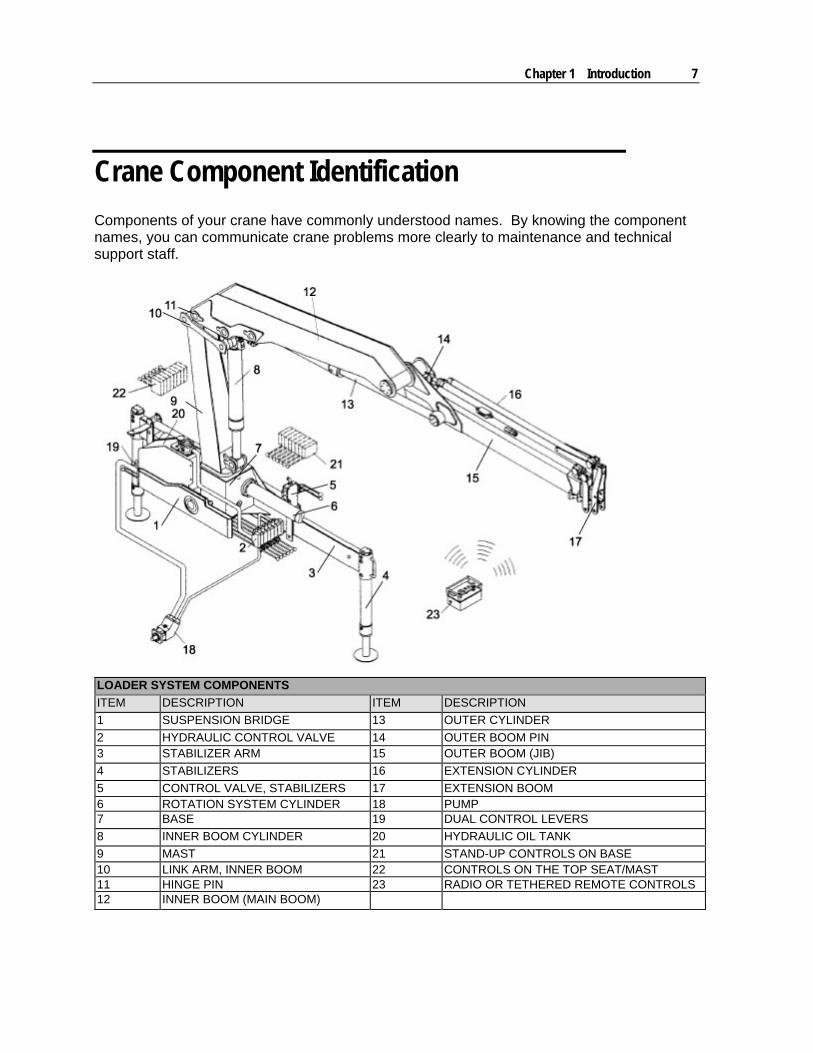
Crane Component Identification
Components of your crane have commonly understood names. By knowing the component names, you can communicate crane problems more clearly to maintenance and technical support staff.
LOADER SYSTEM COMPONENTS
ITEM DESCRIPTION ITEM DESCRIPTION
1 SUSPENSION BRIDGE 13 OUTER CYLINDER
2 HYDRAULIC CONTROL VALVE 14 OUTER BOOM PIN 3 STABILIZER ARM 15 OUTER BOOM (JIB)
4 STABILIZERS 16 EXTENSION CYLINDER
5 CONTROL VALVE, STABILIZERS 17 EXTENSION BOOM 6 ROTATION SYSTEM CYLINDER 18 PUMP 7 BASE 19 DUAL CONTROL LEVERS
8 INNER BOOM CYLINDER 20 HYDRAULIC OIL TANK
9 MAST 21 STAND-UP CONTROLS ON BASE 10 LINK ARM, INNER BOOM 22 CONTROLS ON THE TOP SEAT/MAST 11 HINGE PIN 23 RADIO OR TETHERED REMOTE CONTROLS 12 INNER BOOM (MAIN BOOM)

8 Material Handling Crane Operation & Safety Manual # 99904591
Your hydraulic loader is operated using a pump (18) connected to the hydraulic cylinders via the control valve (2). The pump builds hydraulic pressure which moves the loader when the control valves are moved. When operating the control valve, the cylinders are activated and the speed can be regulated. The oil flows in a closed system with the pump, valves, and hydraulic oil tank. Loaders can be operated from the control valves (2), dual levers (19), stand-up controls (21), top-seat controls (22) or using a radio or tethered remote (23).
NOTE: Your loader is designed to be truck-mounted. Stationary mount applications, on tractors, special purpose vehicles, etc. require a specific agreement with IMT for safe and appropriate installation.
Appropriate Loader Applications
Your IMT loader is used primarily for handling cargo. Using a sling, goods are lifted onto a truck body then unloaded at the destination. You can also use your loader with optional accessories which may increase the application possibilities. Available options include:
Pallet Fork / Stone Clamp - A pallet fork or stone clamp may be mounted on the hook suspension for handling wallboard or other building materials. A rotator may be mounted between the hook suspension and pallet fork to allow load rotation.
Chapter 1 Introduction 9
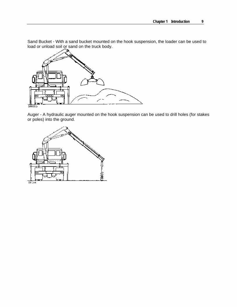
Sand Bucket - With a sand bucket mounted on the hook suspension, the loader can be used to load or unload soil or sand on the truck body.
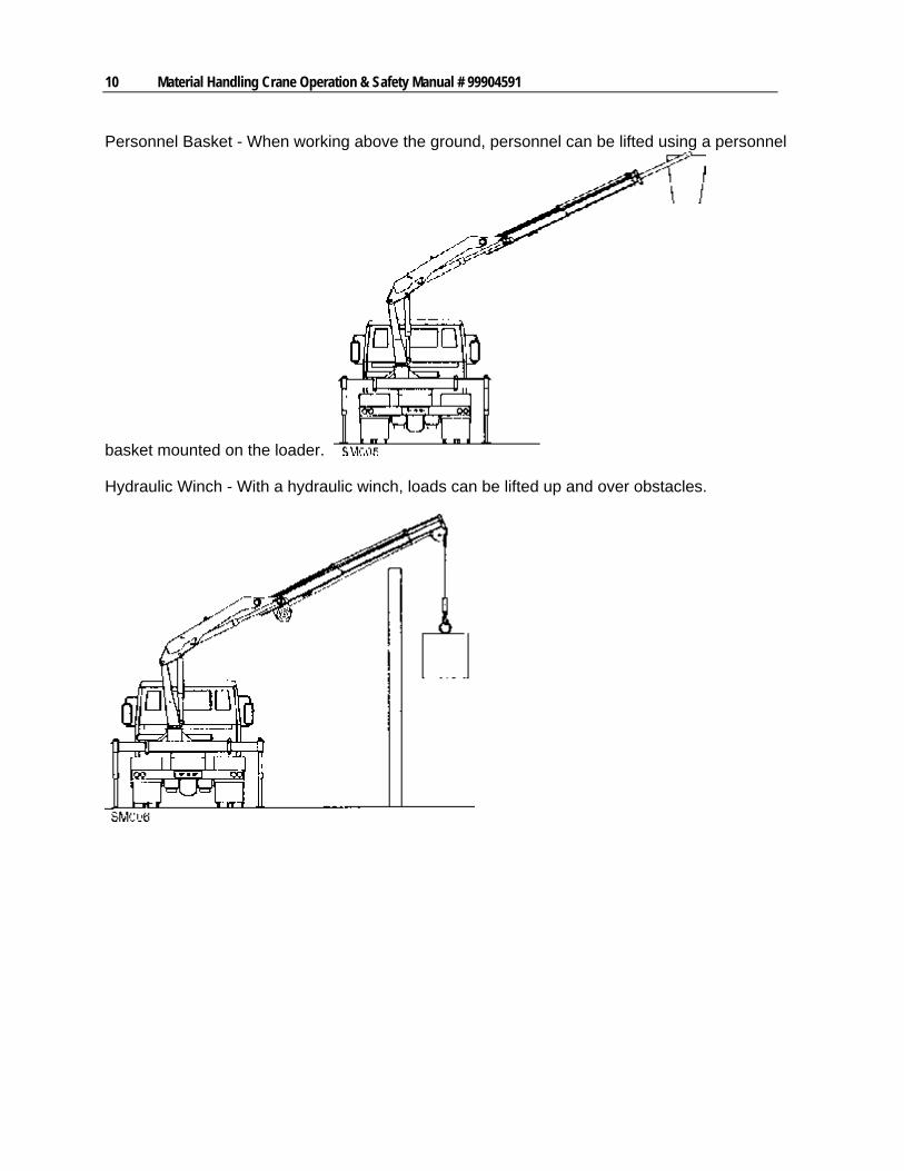
Auger - A hydraulic auger mounted on the hook suspension can be used to drill holes (for stakes or poles) into the ground.
10 Material Handling Crane Operation & Safety Manual # 99904591
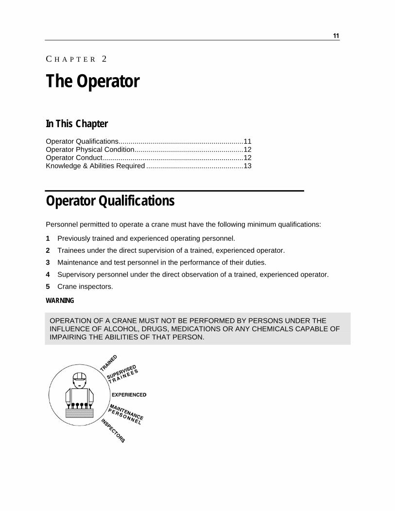
Personnel Basket - When working above the ground, personnel can be lifted using a personnel
basket mounted on the loader.
Hydraulic Winch - With a hydraulic winch, loads can be lifted up and over obstacles.
11
In This Chapter
Operator Qualifications...............................................................11 Operator Physical Condition.......................................................12 Operator Conduct.......................................................................12 Knowledge & Abilities Required .................................................13
Operator Qualifications
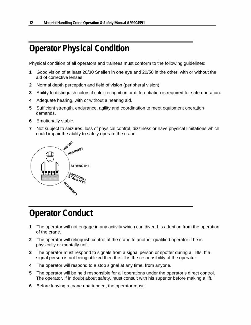
Personnel permitted to operate a crane must have the following minimum qualifications:
1 Previously trained and experienced operating personnel.
2 Trainees under the direct supervision of a trained, experienced operator.
3 Maintenance and test personnel in the performance of their duties.
4 Supervisory personnel under the direct observation of a trained, experienced operator.
5 Crane inspectors.
WARNING
OPERATION OF A CRANE MUST NOT BE PERFORMED BY PERSONS UNDER THE INFLUENCE OF ALCOHOL, DRUGS, MEDICATIONS OR ANY CHEMICALS CAPABLE OF IMPAIRING THE ABILITIES OF THAT PERSON.
C H A P T E R 2
The Operator
12 Material Handling Crane Operation & Safety Manual # 99904591
Operator Physical Condition
Physical condition of all operators and trainees must conform to the following guidelines:
1 Good vision of at least 20/30 Snellen in one eye and 20/50 in the other, with or without the aid of corrective lenses.
2 Normal depth perception and field of vision (peripheral vision).
3 Ability to distinguish colors if color recognition or differentiation is required for safe operation.
4 Adequate hearing, with or without a hearing aid.
5 Sufficient strength, endurance, agility and coordination to meet equipment operation demands.
6 Emotionally stable.
7 Not subject to seizures, loss of physical control, dizziness or have physical limitations which could impair the ability to safely operate the crane.
Operator Conduct 1 The operator will not engage in any activity which can divert his attention from the operation
of the crane.
2 The operator will relinquish control of the crane to another qualified operator if he is physically or mentally unfit.
3 The operator must respond to signals from a signal person or spotter during all lifts. If a signal person is not being utilized then the lift is the responsibility of the operator.
4 The operator will respond to a stop signal at any time, from anyone.
5 The operator will be held responsible for all operations under the operator’s direct control. The operator, if in doubt about safety, must consult with his superior before making a lift.
6 Before leaving a crane unattended, the operator must:
Chapter 2 The Operator 13
a) Land the load.
b) Disengage the main power source.
c) Set any locking devices.
d) Put all controls in the off or neutral position.
e) Secure the crane against accidental travel.
f) Stop the engine.
Knowledge & Abilities Required 1 The ability to read and understand all decals, placards, operation and safety manuals, and
any information relevant to the proper and safe operation of this equipment.
2 Knowledge of any emergency procedures necessary to safe operation.
3 Evidence of, or demonstration of the proper and safe operation of the equipment.
4 Familiarization with all relevant safety codes and governmental regulations pertaining to the operation of this equipment.
5 The responsibility to recognize all maintenance requirements of the equipment being operated.
6 The familiarity with the equipment and all control functions associated with its operation.
7 Have read and understood the procedures for the operation of the equipment.

15
In This Chapter
Operator Responsibilities ........................................................................................ 15 Daily Safety Inspections .......................................................................................... 16 Crane Transport ...................................................................................................... 16 Work Site Planning.................................................................................................. 17 Material Handling Crane Controls ........................................................................... 18 Engaging the PTO................................................................................................... 19 Stabilizers................................................................................................................ 20 Hydraulic Swing-up Stabilizer Legs Controlled by Slewing Cylinder Piston Rod .... 22 Hydraulic Swing-up Stabilizer Legs Controlled by Connecting Rod........................ 25 Unfolding the Loader ............................................................................................... 26 Unfolding a Z-Loader or Grab-Loader ..................................................................... 28 Electrical Hazards ................................................................................................... 29 Safely Operating the Crane..................................................................................... 31 Crane Capacity........................................................................................................ 35 Stowing the Loader ................................................................................................. 36 Stowing a Z-Loader or Grab-Loader without Top Seat Controls ............................. 37 Stowing a Z-Loader or Grab-Loader with Top Seat Controls .................................. 38 ................................................................................................................................ 38 Direction Terminology ............................................................................................. 39
Operator Responsibilities
The loader operator and maintenance staff are responsible for safe operation. They must make sure the loader is operated, inspected, and maintained so it can be used safely. Safety has been designed and manufactured into this equipment by the manufacturer, but only the people working with the crane can insure a safe work environment.
C H A P T E R 3
Crane Operation
16 Material Handling Crane Operation & Safety Manual # 99904591
Daily Safety Inspections
Use the following list as a guide when you are inspecting your unit at start-up and during operation, and log your inspection results using the Crane Log (IMT Manual No. 99900686) or the inspection checklist in the reference section of this manual:
1 Vehicle - Check oil level, battery, lights, brakes, and tires for inflation, pressure, cuts, and loose or missing wheel lugs.
2 Safety Accessories - Check for proper function, oil levels, leaks and malfunctions.
3 Hydraulic Oil Reservoir - Check for proper oil level, above the bottom of the reservoir within the screened area. Check for leaks and blockages.
4 Weldments - Check visually for damage, especially cracks or breaks in welds.
5 Cylinders - Check for leakage and scored rods.
6 Fasteners - Check pins, sheaves, nuts and bolts for breakage, excessive wear and tightness.
7 Hooks - Check for the presence of a safety catch, twists, cracks, or damage.
8 Ropes & Slings - Check for frayed edges, broken strands, kinks, flat spots, and end attachments.
9 Covers & Guards - Check for missing or improperly maintained covers and guards.
10 Remote Control - Check engine stop switch for function and corrosion.
11 Operation Placards and Safety Decals - Check for illegible or missing decals and placards. Refer to the Decal section of this manual for more information on the required decals.
12 Work Area - Check for hazards including powerlines, obstructions, etc.
13 Replace or repair any items as needed prior to equipment operation.
Crane Transport
Before transporting the crane, make sure:
1 The crane is stowed its stored position.
2 The stabilizers are securely stowed and NOT extended horizontally or vertically.
3 Hook and sheave assemblies are securely fastened to prevent swinging.
4 All loose accessories, tools and remote controls are securely stored in their respective compartments or fasteners.
5 The PTO is disengaged.
6 DO NOT release the parking brake until all of the above procedures are completed.
Chapter 3 Crane Operation 17
7 DO NOT drive the carrier vehicle while a load is present on the hook.
8 DO NOT drive the carrier vehicle with less than the proper tire inflation pressure.
9 DO NOT drive the carrier vehicle in areas where the vertical clearance is not known.
10 DO NOT allow personnel to ride on the equipment during transport.
11 DO NOT attempt to operate the vehicle or equipment without a signal person if visibility is limited.
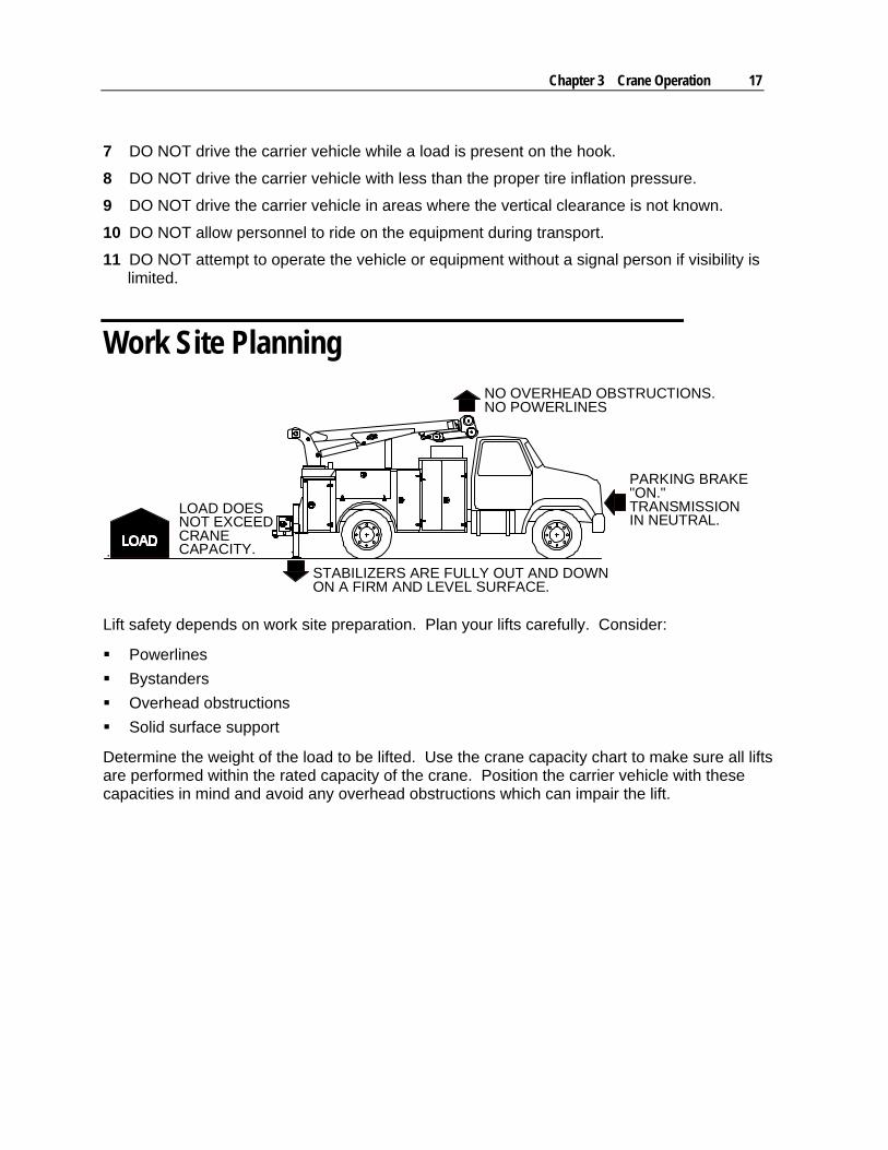
Work Site Planning
LOAD DOESNOT EXCEEDCRANECAPACITY.
STABILIZERS ARE FULLY OUT AND DOWNON A FIRM AND LEVEL SURFACE.
NO OVERHEAD OBSTRUCTIONS.NO POWERLINES
PARKING BRAKE"ON."TRANSMISSIONIN NEUTRAL.
Lift safety depends on work site preparation. Plan your lifts carefully. Consider:
Powerlines
Bystanders
Overhead obstructions
Solid surface support
Determine the weight of the load to be lifted. Use the crane capacity chart to make sure all lifts are performed within the rated capacity of the crane. Position the carrier vehicle with these capacities in mind and avoid any overhead obstructions which can impair the lift.

18 Material Handling Crane Operation & Safety Manual # 99904591
WARNING
VISIBILITY IS CRITICAL! Park the vehicle so the operator can see all of the working area!
DANGER
AVOID POWERLINES! Read and understand the Electrical Hazard section of this manual before attempting any crane operations near powerlines.
Position the carrier vehicle so that when the crane is fully extended it can't contact electrically charged lines or apparatus. Ten feet (3.05 meters) is the minimum distance that any portion of the crane, loadline or load can be to electrical lines carrying up to 50,000 Volts. Add a minimum of 12 inches (30.5 centimeters) to that distance for every additional 30,000 Volts or less. In windy conditions, allow extra space for powerline and loadline sway and deflection. Provide additional clearance between the crane and electrical lines. If the powerline or apparatus voltage is not known, contact the electrical utility prior to the lift. If a lift is impossible to perform within the minimum distance between electrical source and crane, ask the power company to de-energize the powerlines or apparatus before any lift is attempted. Use a qualified signal person or spotter when working near electrical sources, even if the powerline has been de-energized.
Chapter 3 Crane Operation 19
Material Handling Crane Controls
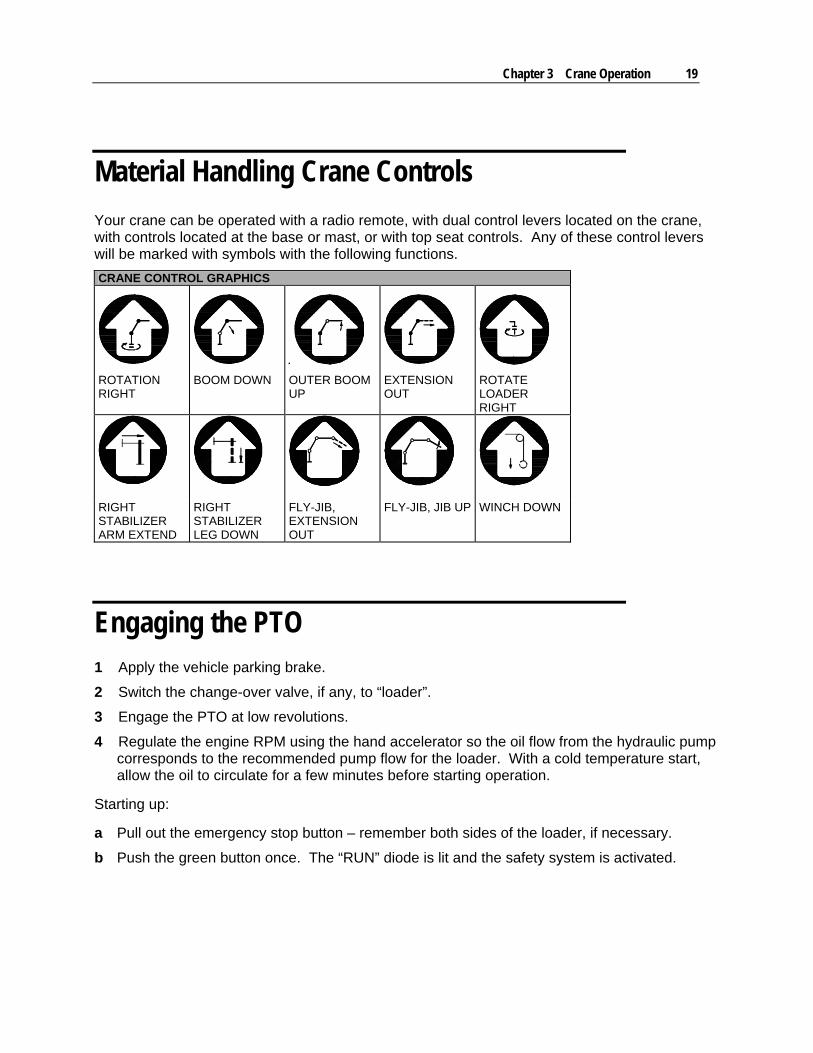
Your crane can be operated with a radio remote, with dual control levers located on the crane, with controls located at the base or mast, or with top seat controls. Any of these control levers will be marked with symbols with the following functions.
CRANE CONTROL GRAPHICS
ROTATION RIGHT
BOOM DOWN OUTER BOOM UP
EXTENSION OUT
ROTATE LOADER RIGHT
RIGHT STABILIZER ARM EXTEND
RIGHT STABILIZER LEG DOWN
FLY-JIB, EXTENSION OUT
FLY-JIB, JIB UP WINCH DOWN
Engaging the PTO 1 Apply the vehicle parking brake.
2 Switch the change-over valve, if any, to “loader”.
3 Engage the PTO at low revolutions.
4 Regulate the engine RPM using the hand accelerator so the oil flow from the hydraulic pump corresponds to the recommended pump flow for the loader. With a cold temperature start, allow the oil to circulate for a few minutes before starting operation.
Starting up:
a Pull out the emergency stop button – remember both sides of the loader, if necessary.
b Push the green button once. The “RUN” diode is lit and the safety system is activated.
20 Material Handling Crane Operation & Safety Manual # 99904591
Stabilizers
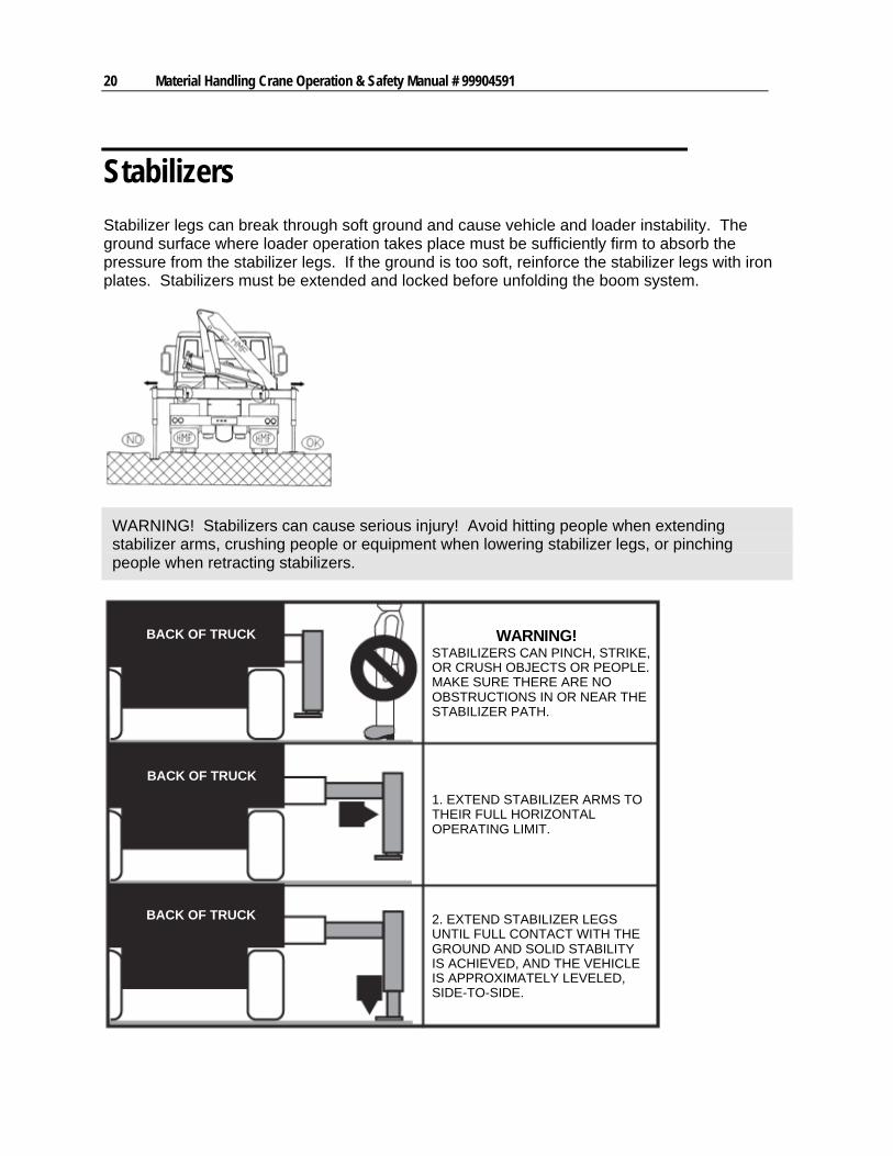
Stabilizer legs can break through soft ground and cause vehicle and loader instability. The ground surface where loader operation takes place must be sufficiently firm to absorb the pressure from the stabilizer legs. If the ground is too soft, reinforce the stabilizer legs with iron plates. Stabilizers must be extended and locked before unfolding the boom system.
WARNING! Stabilizers can cause serious injury! Avoid hitting people when extending stabilizer arms, crushing people or equipment when lowering stabilizer legs, or pinching people when retracting stabilizers.
BACK OF TRUCK
BACK OF TRUCK
BACK OF TRUCK
STABILIZERS CAN PINCH, STRIKE,OR CRUSH OBJECTS OR PEOPLE.MAKE SURE THERE ARE NOOBSTRUCTIONS IN OR NEAR THESTABILIZER PATH.
WARNING!
1. EXTEND STABILIZER ARMS TOTHEIR FULL HORIZONTALOPERATING LIMIT.
2. EXTEND STABILIZER LEGSUNTIL FULL CONTACT WITH THEGROUND AND SOLID STABILITYIS ACHIEVED, AND THE VEHICLEIS APPROXIMATELY LEVELED,SIDE-TO-SIDE.
Chapter 3 Crane Operation 21
STABILIZER SET-UP
1 The loader operates best when positioned as close to level as possible. Park the vehicle in the most level spot if lifting a load on an inclined surface.
2 Make sure that the ground is not slippery to avoid vehicle and loader skidding during loader operation. Chock wheels if needed.
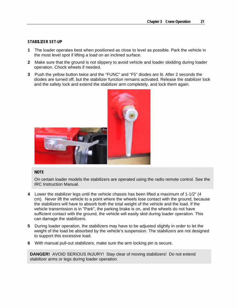
3 Push the yellow button twice and the “FUNC” and “F5” diodes are lit. After 2 seconds the diodes are turned off, but the stabilizer function remains activated. Release the stabilizer lock and the safety lock and extend the stabilizer arm completely, and lock them again.
NOTE
On certain loader models the stabilizers are operated using the radio remote control. See the IRC Instruction Manual.
4 Lower the stabilizer legs until the vehicle chassis has been lifted a maximum of 1-1/2" (4 cm). Never lift the vehicle to a point where the wheels lose contact with the ground, because the stabilizers will have to absorb both the total weight of the vehicle and the load. If the vehicle transmission is in "Park", the parking brake is on, and the wheels do not have sufficient contact with the ground, the vehicle will easily skid during loader operation. This can damage the stabilizers.
5 During loader operation, the stabilizers may have to be adjusted slightly in order to let the weight of the load be absorbed by the vehicle’s suspension. The stabilizers are not designed to support this excessive load.
6 With manual pull-out stabilizers, make sure the arm locking pin is secure.
DANGER! AVOID SERIOUS INJURY! Stay clear of moving stabilizers! Do not extend stabilizer arms or legs during loader operation.
22 Material Handling Crane Operation & Safety Manual # 99904591
Hydraulic Swing-up Stabilizer Legs Controlled by Slewing Cylinder Piston Rod
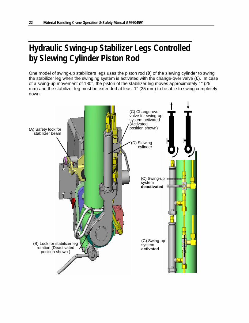
One model of swing-up stabilizers legs uses the piston rod (D) of the slewing cylinder to swing the stabilizer leg when the swinging system is activated with the change-over valve (C). In case of a swing-up movement of 180°, the piston of the stabilizer leg moves approximately 1" (25 mm) and the stabilizer leg must be extended at least 1" (25 mm) to be able to swing completely down.
(A) Safety lock forstabilizer beam
(D) Slewingcylinder
(C) Swing-upsystemdeactivated
(C) Swing-upsystemactivated
(B) Lock for stabilizer legrotation (Deactivated
position shown )
(C) Change-overvalve for swing-upsystem activated(Activatedposition shown)
Chapter 3 Crane Operation 23
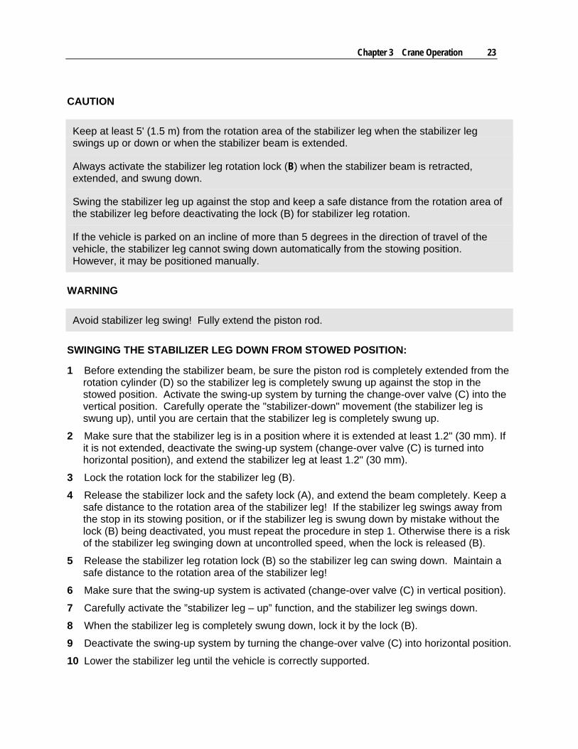
CAUTION
Keep at least 5' (1.5 m) from the rotation area of the stabilizer leg when the stabilizer leg swings up or down or when the stabilizer beam is extended.
Always activate the stabilizer leg rotation lock (B) when the stabilizer beam is retracted, extended, and swung down.
Swing the stabilizer leg up against the stop and keep a safe distance from the rotation area of the stabilizer leg before deactivating the lock (B) for stabilizer leg rotation.
If the vehicle is parked on an incline of more than 5 degrees in the direction of travel of the vehicle, the stabilizer leg cannot swing down automatically from the stowing position. However, it may be positioned manually.
WARNING
Avoid stabilizer leg swing! Fully extend the piston rod.
SWINGING THE STABILIZER LEG DOWN FROM STOWED POSITION:
1 Before extending the stabilizer beam, be sure the piston rod is completely extended from the rotation cylinder (D) so the stabilizer leg is completely swung up against the stop in the stowed position. Activate the swing-up system by turning the change-over valve (C) into the vertical position. Carefully operate the "stabilizer-down" movement (the stabilizer leg is swung up), until you are certain that the stabilizer leg is completely swung up.
2 Make sure that the stabilizer leg is in a position where it is extended at least 1.2" (30 mm). If it is not extended, deactivate the swing-up system (change-over valve (C) is turned into horizontal position), and extend the stabilizer leg at least 1.2" (30 mm).
3 Lock the rotation lock for the stabilizer leg (B).
4 Release the stabilizer lock and the safety lock (A), and extend the beam completely. Keep a safe distance to the rotation area of the stabilizer leg! If the stabilizer leg swings away from the stop in its stowing position, or if the stabilizer leg is swung down by mistake without the lock (B) being deactivated, you must repeat the procedure in step 1. Otherwise there is a risk of the stabilizer leg swinging down at uncontrolled speed, when the lock is released (B).
5 Release the stabilizer leg rotation lock (B) so the stabilizer leg can swing down. Maintain a safe distance to the rotation area of the stabilizer leg!
6 Make sure that the swing-up system is activated (change-over valve (C) in vertical position).
7 Carefully activate the ”stabilizer leg – up” function, and the stabilizer leg swings down.
8 When the stabilizer leg is completely swung down, lock it by the lock (B).
9 Deactivate the swing-up system by turning the change-over valve (C) into horizontal position.
10 Lower the stabilizer leg until the vehicle is correctly supported.
24 Material Handling Crane Operation & Safety Manual # 99904591
SWINGING UP THE STABILIZER LEG INTO THE STOWED POSITION:
1 Swing up the stabilizer leg completely and then extend the stabilizer cylinder a little bit again to release the oil pressure. A blocked pressure may make it difficult to swing down the stabilizer leg completely.
2 Release the stabilizer leg rotation lock (B).
3 Activate the swing-up system (C) (change-over valve in vertical position).
4 Carefully operate the ”stabilizer leg – down” function, and the stabilizer leg swings up.
5 When the stabilizer leg is completely swung up against stop in its stowing position, lock it in place (B).
6 Retract the stabilizer beam and lock the stabilizer lock and the safety lock (A).
7 Deactivate the swing-up system by turning the change-over valve (C) into horizontal position.
Chapter 3 Crane Operation 25
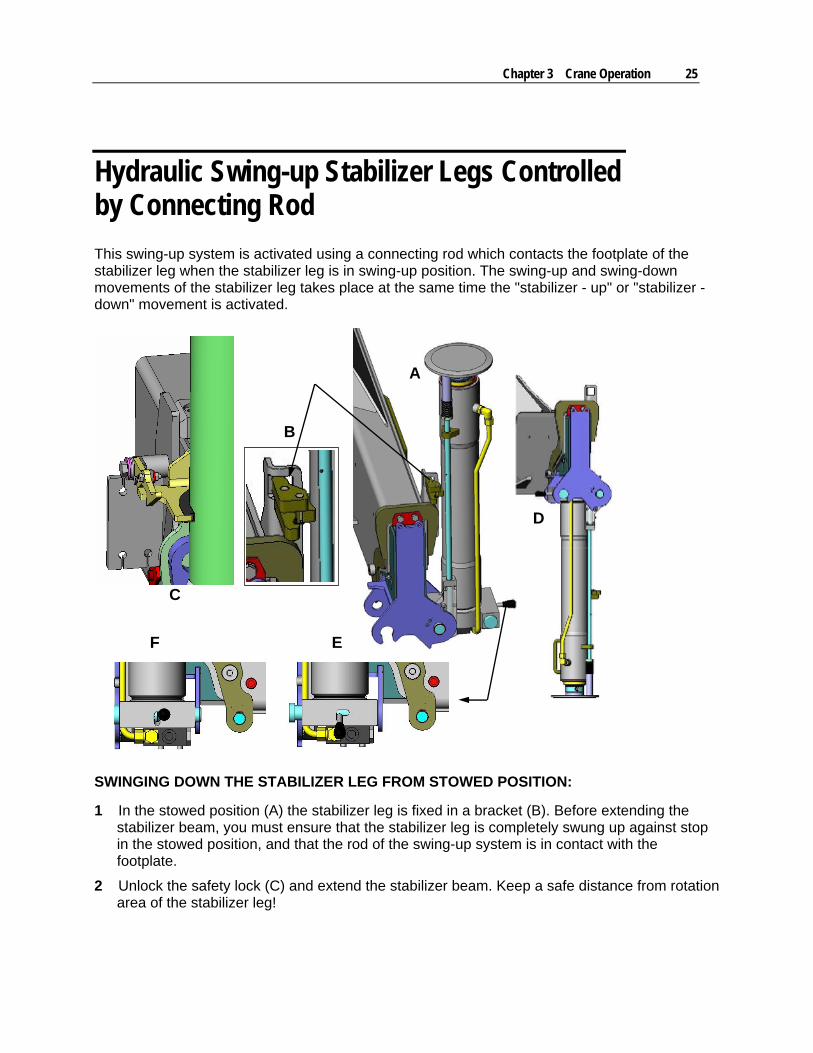
Hydraulic Swing-up Stabilizer Legs Controlled by Connecting Rod
This swing-up system is activated using a connecting rod which contacts the footplate of the stabilizer leg when the stabilizer leg is in swing-up position. The swing-up and swing-down movements of the stabilizer leg takes place at the same time the "stabilizer - up" or "stabilizer - down" movement is activated.
D
C
EF
B
A
SWINGING DOWN THE STABILIZER LEG FROM STOWED POSITION:
1 In the stowed position (A) the stabilizer leg is fixed in a bracket (B). Before extending the stabilizer beam, you must ensure that the stabilizer leg is completely swung up against stop in the stowed position, and that the rod of the swing-up system is in contact with the footplate.
2 Unlock the safety lock (C) and extend the stabilizer beam. Keep a safe distance from rotation area of the stabilizer leg!
26 Material Handling Crane Operation & Safety Manual # 99904591
3 Unlock the lock for rotation of the stabilizer leg – position (E) so that it is possible to swing down the stabilizer leg. Keep a safe distance to the rotation area of the stabilizer leg! If you try to swing down the stabilizer leg without unlocking this lock, you must repeat the procedure in step 1. Otherwise there is a risk of the stabilizer leg swinging down too fast after deactivating the lock (E).
4 Carefully operate the ”stabilizer leg – down” function. The stabilizer leg will swing down.
5 When the stabilizer leg is completely swung down, lock the rotation stabilizer leg lock – position (F).
6 Lower the stabilizer leg until the vehicle is correctly supported.
SWINGING UP THE STABILIZER LEG INTO STOWED POSITION:
1 Raise the stabilizer leg slightly until the footplate no longer touches the surface.
2 Unlock the lock for rotation of the stabilizer leg - position (E).
3 Raise the stabilizer leg – the last bit very slowly – until the rod of the swing-up system is in contact with the footplate.
4 Carefully activate the ”stabilizer leg – up” function, and the stabilizer leg swings up.
5 When the stabilizer leg is completely swung up against stop in stowing position, activate the lock for rotation of the stabilizer leg – position (F).
6 Retract the stabilizer beam and activate the safety lock (C).
Chapter 3 Crane Operation 27
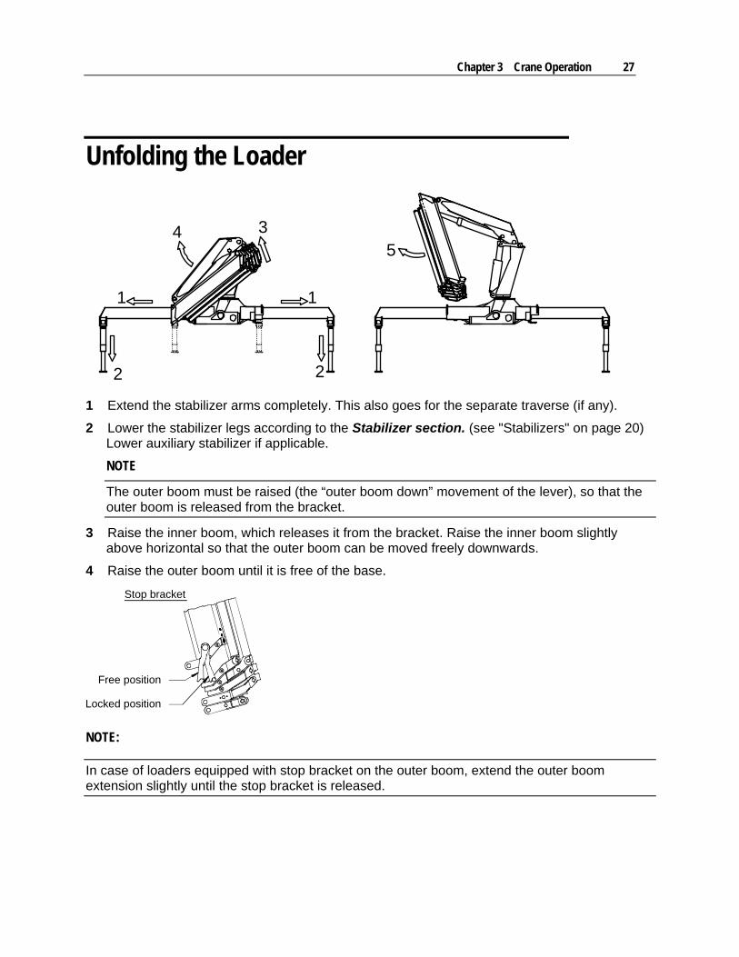
Unfolding the Loader
1 1
2 2
345
1 Extend the stabilizer arms completely. This also goes for the separate traverse (if any).
2 Lower the stabilizer legs according to the Stabilizer section. (see "Stabilizers" on page 20) Lower auxiliary stabilizer if applicable.
NOTE
The outer boom must be raised (the “outer boom down” movement of the lever), so that the outer boom is released from the bracket.
3 Raise the inner boom, which releases it from the bracket. Raise the inner boom slightly above horizontal so that the outer boom can be moved freely downwards.
4 Raise the outer boom until it is free of the base.
Free position
Locked position
Stop bracket
NOTE:
In case of loaders equipped with stop bracket on the outer boom, extend the outer boom extension slightly until the stop bracket is released.
28 Material Handling Crane Operation & Safety Manual # 99904591
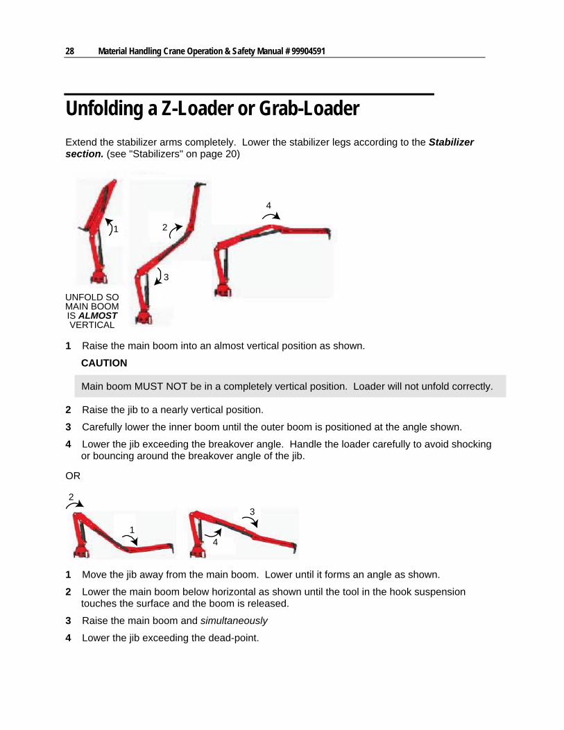
Unfolding a Z-Loader or Grab-Loader
Extend the stabilizer arms completely. Lower the stabilizer legs according to the Stabilizer section. (see "Stabilizers" on page 20)
UNFOLD SOMAIN BOOMIS ALMOSTVERTICAL
1
4
3
2
1 Raise the main boom into an almost vertical position as shown.
CAUTION
Main boom MUST NOT be in a completely vertical position. Loader will not unfold correctly.
2 Raise the jib to a nearly vertical position.
3 Carefully lower the inner boom until the outer boom is positioned at the angle shown.
4 Lower the jib exceeding the breakover angle. Handle the loader carefully to avoid shocking or bouncing around the breakover angle of the jib.
OR
2
14
3
1 Move the jib away from the main boom. Lower until it forms an angle as shown.
2 Lower the main boom below horizontal as shown until the tool in the hook suspension touches the surface and the boom is released.
3 Raise the main boom and simultaneously
4 Lower the jib exceeding the dead-point.
Chapter 3 Crane Operation 29
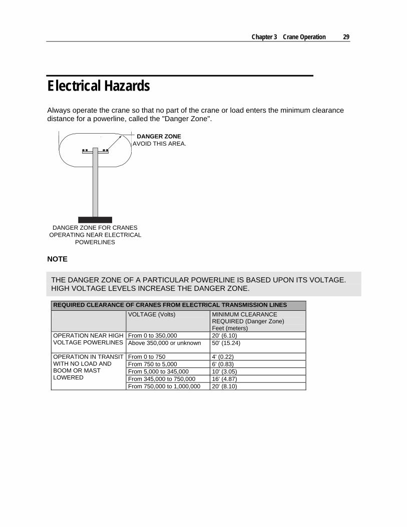
Electrical Hazards
Always operate the crane so that no part of the crane or load enters the minimum clearance distance for a powerline, called the "Danger Zone".
DANGER ZONEAVOID THIS AREA.
DANGER ZONE FOR CRANESOPERATING NEAR ELECTRICAL
POWERLINES
NOTE
THE DANGER ZONE OF A PARTICULAR POWERLINE IS BASED UPON ITS VOLTAGE. HIGH VOLTAGE LEVELS INCREASE THE DANGER ZONE.
REQUIRED CLEARANCE OF CRANES FROM ELECTRICAL TRANSMISSION LINES
VOLTAGE (Volts) MINIMUM CLEARANCE REQUIRED (Danger Zone) Feet (meters)
From 0 to 350,000 20' (6.10) OPERATION NEAR HIGH VOLTAGE POWERLINES
Above 350,000 or unknown 50' (15.24)
From 0 to 750 4' (0.22) From 750 to 5,000 6' (0.83) From 5,000 to 345,000 10' (3.05) From 345,000 to 750,000 16' (4.87)
OPERATION IN TRANSIT WITH NO LOAD AND BOOM OR MAST LOWERED From 750,000 to 1,000,000 20' (8.10)
30 Material Handling Crane Operation & Safety Manual # 99904591
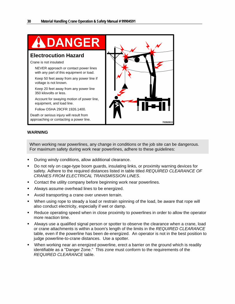
70392813
Electrocution HazardCrane is not insulated
NEVER approach or contact power lineswith any part of this equipment or load.
Keep 50 feet away from any power line ifvoltage is not known.
Keep 20 feet away from any power line350 kilovolts or less.
Account for swaying motion of power line,equipment, and load line.
Follow OSHA 29CFR 1926.1400.
Death or serious injury will result fromapproaching or contacting a power line.
WARNING
When working near powerlines, any change in conditions or the job site can be dangerous. For maximum safety during work near powerlines, adhere to these guidelines:
During windy conditions, allow additional clearance.
Do not rely on cage-type boom guards, insulating links, or proximity warning devices for safety. Adhere to the required distances listed in table titled REQUIRED CLEARANCE OF CRANES FROM ELECTRICAL TRANSMISSION LINES.
Contact the utility company before beginning work near powerlines.
Always assume overhead lines to be energized.
Avoid transporting a crane over uneven terrain.
When using rope to steady a load or restrain spinning of the load, be aware that rope will also conduct electricity, especially if wet or damp.
Reduce operating speed when in close proximity to powerlines in order to allow the operator more reaction time.
Always use a qualified signal person or spotter to observe the clearance when a crane, load or crane attachments is within a boom's length of the limits in the REQUIRED CLEARANCE table, even if the powerline has been de-energized. An operator is not in the best position to judge powerline-to-crane distances. Use a spotter.
When working near an energized powerline, erect a barrier on the ground which is readily identifiable as a "Danger Zone." This zone must conform to the requirements of the REQUIRED CLEARANCE table.
Chapter 3 Crane Operation 31
IF ELECTRICAL CONTACT OCCURS:
1 Shut off all power.
2 Break contact of any person in contact with a live conductor by using rubber hose, dry rope, or dry wood. DO NOT attempt this unless you are certain that all power is off.
3 Call 911 or the local emergency service.
4 Administer first aid.
5 Avoid the area around the crane, as high voltage traveling through a crane will charge the ground.
ELECTRICAL CONTACT FOLLOW-UP:
1 Inspect and repair any equipment affected by electrical contact.
2 Replace any wire rope which has had high voltage contact.
Safely Operating the Crane
PRIOR TO LIFTING A LOAD
1 Read and understand all safety and operating decals before operating the crane.
2 Be sure the carrier vehicle’s transmission is in neutral and the parking brake is on before engaging the PTO.
3 Wear a hard hat and goggles or safety glasses during operation.
4 Avoid work around powerlines. See Crane Operation Near Powerlines (see "Electrical Hazards" on page 29).
LOAD SET-UP
1 Set-up stabilizers per Stabilizers (see "Stabilizers" on page 20) section.
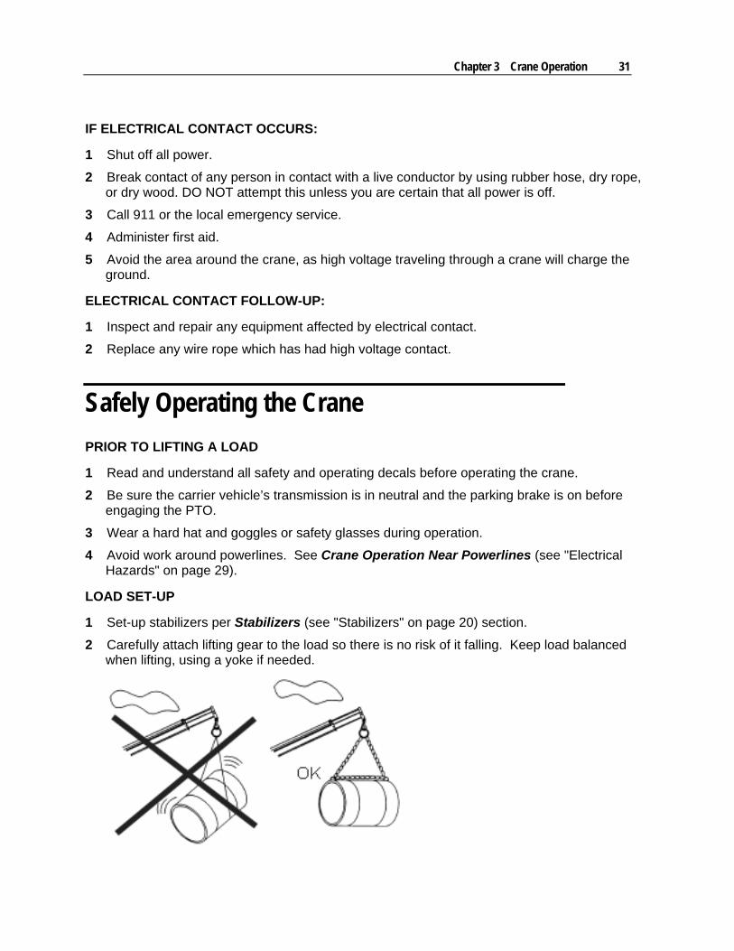
2 Carefully attach lifting gear to the load so there is no risk of it falling. Keep load balanced when lifting, using a yoke if needed.
32 Material Handling Crane Operation & Safety Manual # 99904591
3 Secure all unneeded manual boom extensions before operating the crane.
4 Know the position of the booms at all times while operating the crane. Keep all unnecessary personnel away from the loader and working radius. Be sure there are no areas with an obstructed view or obstacles.
5 Eliminate swing by positioning the boom tip directly over the center of the load before lifting.
6 Check the safety of the load by first lifting the load barely off the ground.
CAPACITY
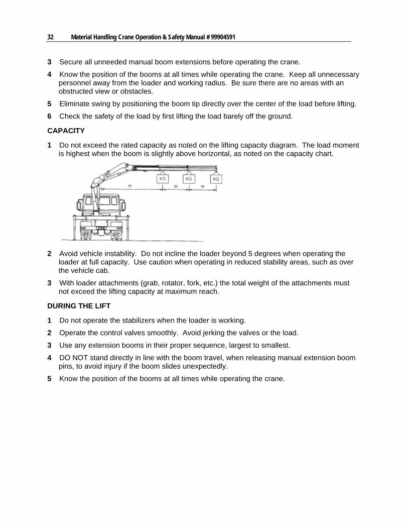
1 Do not exceed the rated capacity as noted on the lifting capacity diagram. The load moment is highest when the boom is slightly above horizontal, as noted on the capacity chart.
2 Avoid vehicle instability. Do not incline the loader beyond 5 degrees when operating the loader at full capacity. Use caution when operating in reduced stability areas, such as over the vehicle cab.
3 With loader attachments (grab, rotator, fork, etc.) the total weight of the attachments must not exceed the lifting capacity at maximum reach.
DURING THE LIFT
1 Do not operate the stabilizers when the loader is working.
2 Operate the control valves smoothly. Avoid jerking the valves or the load.
3 Use any extension booms in their proper sequence, largest to smallest.
4 DO NOT stand directly in line with the boom travel, when releasing manual extension boom pins, to avoid injury if the boom slides unexpectedly.
5 Know the position of the booms at all times while operating the crane.
Chapter 3 Crane Operation 33
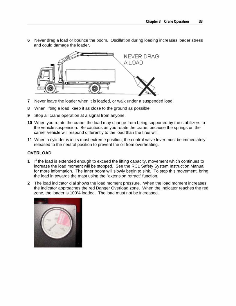
6 Never drag a load or bounce the boom. Oscillation during loading increases loader stress and could damage the loader.
7 Never leave the loader when it is loaded, or walk under a suspended load.
8 When lifting a load, keep it as close to the ground as possible.
9 Stop all crane operation at a signal from anyone.
10 When you rotate the crane, the load may change from being supported by the stabilizers to the vehicle suspension. Be cautious as you rotate the crane, because the springs on the carrier vehicle will respond differently to the load than the tires will.
11 When a cylinder is in its most extreme position, the control valve lever must be immediately released to the neutral position to prevent the oil from overheating.
OVERLOAD
1 If the load is extended enough to exceed the lifting capacity, movement which continues to increase the load moment will be stopped. See the RCL Safety System Instruction Manual for more information. The inner boom will slowly begin to sink. To stop this movement, bring the load in towards the mast using the "extension retract" function.
2 The load indicator dial shows the load moment pressure. When the load moment increases, the indicator approaches the red Danger Overload zone. When the indicator reaches the red zone, the loader is 100% loaded. The load must not be increased.
34 Material Handling Crane Operation & Safety Manual # 99904591
EMERGENCY STOP
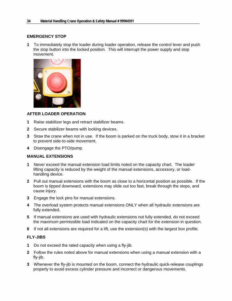
1 To immediately stop the loader during loader operation, release the control lever and push the stop button into the locked position. This will interrupt the power supply and stop movement.
AFTER LOADER OPERATION
1 Raise stabilizer legs and retract stabilizer beams.
2 Secure stabilizer beams with locking devices.
3 Stow the crane when not in use. If the boom is parked on the truck body, stow it in a bracket to prevent side-to-side movement.
4 Disengage the PTO/pump.
MANUAL EXTENSIONS
1 Never exceed the manual extension load limits noted on the capacity chart. The loader lifting capacity is reduced by the weight of the manual extensions, accessory, or load-handling device.
2 Pull out manual extensions with the boom as close to a horizontal position as possible. If the boom is tipped downward, extensions may slide out too fast, break through the stops, and cause injury.
3 Engage the lock pins for manual extensions.
4 The overload system protects manual extensions ONLY when all hydraulic extensions are fully extended.
5 If manual extensions are used with hydraulic extensions not fully extended, do not exceed the maximum permissible load indicated on the capacity chart for the extension in question.
6 If not all extensions are required for a lift, use the extension(s) with the largest box profile.
FLY-JIBS
1 Do not exceed the rated capacity when using a fly-jib.
2 Follow the rules noted above for manual extensions when using a manual extension with a fly-jib.
3 Whenever the fly-jib is mounted on the boom, connect the hydraulic quick-release couplings properly to avoid excess cylinder pressure and incorrect or dangerous movements.
Chapter 3 Crane Operation 35
Crane Capacity
The IMT crane is designed to lift specific loads. These loads are defined on the capacity placard mounted near the operator’s station and on the crane. Exceeding the limits presented on the capacity placard will create severe safety hazards and will shorten the life of the crane. The operator and other concerned personnel must know the load capacity of the crane and the weight of the load being lifted!
The capacity chart for each model is located in the specific crane technical specifications manual and on placards on the crane and body.
WARNING
NEVER EXCEED THE CRANE’S RATED LOAD CAPACITIES. DOING SO WILL CAUSE STRUCTURAL DAMAGE AND DAMAGE TO WINCHES AND CABLES WHICH CAN LEAD TO DEATH OR SERIOUS INJURY.
NOTE
CAPACITY PLACARDS ARE INTENTIONALLY LOCATED NEAR THE OPERATOR TO ASSURE READY REFERENCE IN DETERMINING WHEN A LOAD CAN OR CANNOT BE HANDLED.
LOAD LIMIT INFORMATION ON THE CAPACITY PLACARD IS FORMULATED ON 85% OF TIPPING. TIPPING REFERS TO THE CRANE ACTUALLY TIPPING WITH ITS OPPOSITE STABILIZER AND TIRES HAVING BROKEN CONTACT WITH THE SURFACE.
Prior to lifting a load:
1 Determine the weight of the load.
2 Determine the weight of any load handling devices.
3 Add the weight of the load and the weight of the load handling devices. The sum is the total weight of the load being lifted.
4 Determine the distance from the centerline of crane rotation to the centerline of the load being lifted.
5 Determine the distance from the centerline of crane rotation to the centerline of where the load is to be moved to.
6 The actual distance used should be figured as the larger of items 4 and 5 above.
36 Material Handling Crane Operation & Safety Manual # 99904591
Stowing the Loader
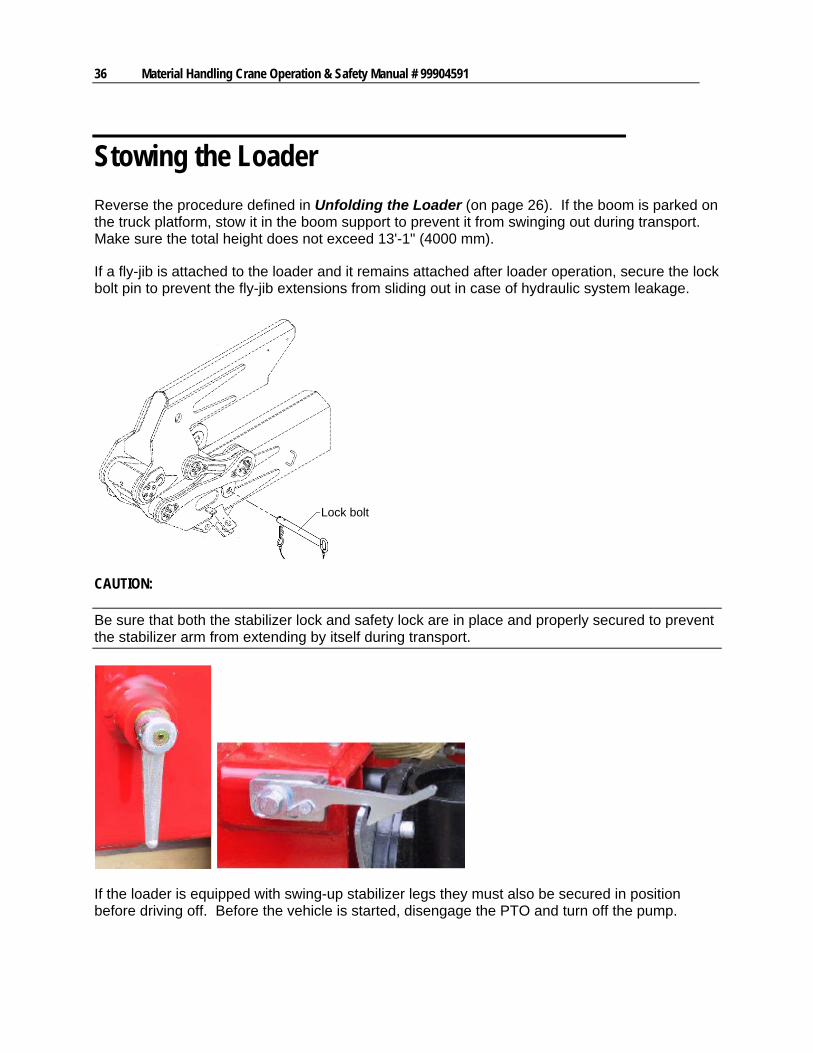
Reverse the procedure defined in Unfolding the Loader (on page 26). If the boom is parked on the truck platform, stow it in the boom support to prevent it from swinging out during transport. Make sure the total height does not exceed 13'-1" (4000 mm).
If a fly-jib is attached to the loader and it remains attached after loader operation, secure the lock bolt pin to prevent the fly-jib extensions from sliding out in case of hydraulic system leakage.
Lock bolt
CAUTION:
Be sure that both the stabilizer lock and safety lock are in place and properly secured to prevent the stabilizer arm from extending by itself during transport.
If the loader is equipped with swing-up stabilizer legs they must also be secured in position before driving off. Before the vehicle is started, disengage the PTO and turn off the pump.
Chapter 3 Crane Operation 37
Stowing a Z-Loader or Grab-Loader without Top Seat Controls
12
3
4
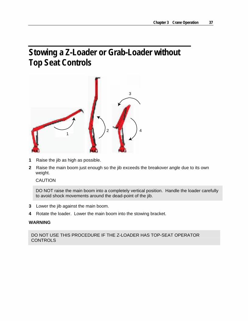
1 Raise the jib as high as possible.
2 Raise the main boom just enough so the jib exceeds the breakover angle due to its own weight.
CAUTION
DO NOT raise the main boom into a completely vertical position. Handle the loader carefully to avoid shock movements around the dead-point of the jib.
3 Lower the jib against the main boom.
4 Rotate the loader. Lower the main boom into the stowing bracket.
WARNING
DO NOT USE THIS PROCEDURE IF THE Z-LOADER HAS TOP-SEAT OPERATOR CONTROLS
38 Material Handling Crane Operation & Safety Manual # 99904591
Stowing a Z-Loader or Grab-Loader with Top Seat Controls
41
2 3
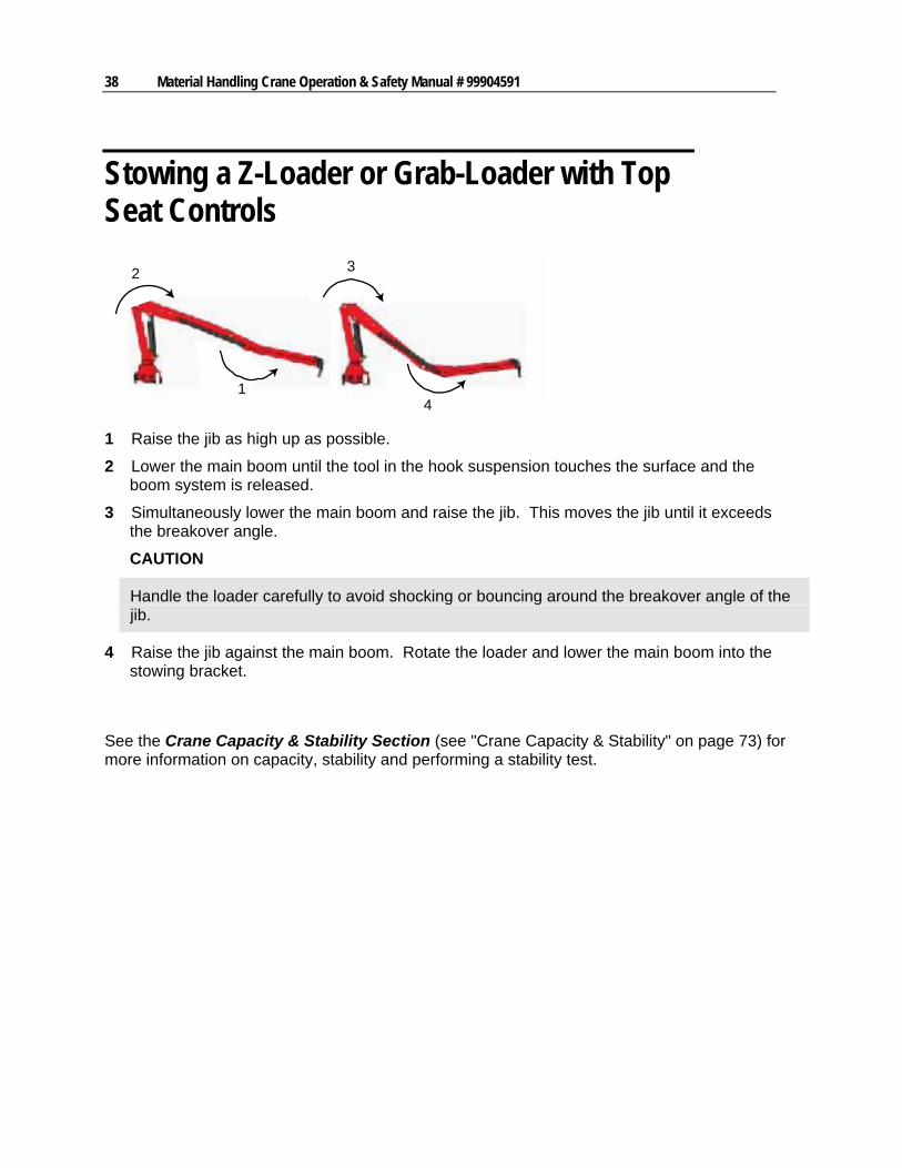
1 Raise the jib as high up as possible.
2 Lower the main boom until the tool in the hook suspension touches the surface and the boom system is released.
3 Simultaneously lower the main boom and raise the jib. This moves the jib until it exceeds the breakover angle.
CAUTION
Handle the loader carefully to avoid shocking or bouncing around the breakover angle of the jib.
4 Raise the jib against the main boom. Rotate the loader and lower the main boom into the stowing bracket.
See the Crane Capacity & Stability Section (see "Crane Capacity & Stability" on page 73) for more information on capacity, stability and performing a stability test.
Chapter 3 Crane Operation 39
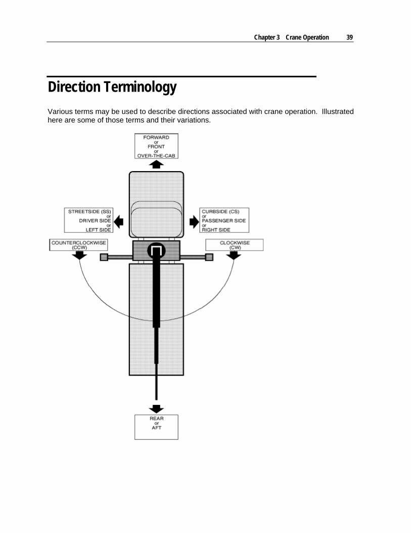
Direction Terminology
Various terms may be used to describe directions associated with crane operation. Illustrated here are some of those terms and their variations.

41
In This Chapter
Danger Decals............................................................................41 Decal Placement - Material Handling Cranes ............................42 Danger Decal Figures ................................................................43 Instructional Decals ....................................................................46
Danger Decals
All operators must familiarize themselves with the “DANGER” decals shown in this section. Your equipment may have additional safety decals that are not described here. Any safety decals affixed to your equipment must be identified, read and understood.
The materials and adhesives used in the production of these decals were designed for maximum durability, adhesion and legibility. Nevertheless, if a decal (including capacity chart) becomes damaged or illegible, replace it at your earliest opportunity. If a crane is repaired or repainted, replace all decals before the crane is put back into service. Individual decals as well as complete decal kits are available from IMT.
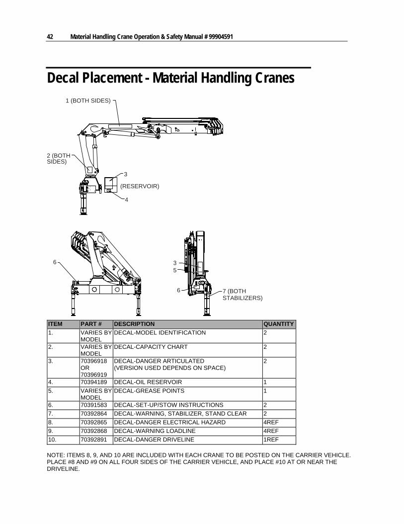
The following figures show examples of the safety decals used on IMT cranes, along with an explanation of their purpose, location, and the normal quantity used on each crane.
C H A P T E R 4
Crane Decals
42 Material Handling Crane Operation & Safety Manual # 99904591
Decal Placement - Material Handling Cranes 1 (BOTH SIDES)
2 (BOTHSIDES)
5
3
4
(RESERVOIR)
3
6 7 (BOTHSTABILIZERS)
6
ITEM PART # DESCRIPTION QUANTITY
1. VARIES BY MODEL
DECAL-MODEL IDENTIFICATION 2
2. VARIES BY MODEL
DECAL-CAPACITY CHART 2
3. 70396918 OR 70396919
DECAL-DANGER ARTICULATED (VERSION USED DEPENDS ON SPACE)
2
4. 70394189 DECAL-OIL RESERVOIR 1
5. VARIES BY MODEL
DECAL-GREASE POINTS 1
6. 70391583 DECAL-SET-UP/STOW INSTRUCTIONS 2
7. 70392864 DECAL-WARNING, STABILIZER, STAND CLEAR 2
8. 70392865 DECAL-DANGER ELECTRICAL HAZARD 4REF
9. 70392868 DECAL-WARNING LOADLINE 4REF
10. 70392891 DECAL-DANGER DRIVELINE 1REF
NOTE: ITEMS 8, 9, AND 10 ARE INCLUDED WITH EACH CRANE TO BE POSTED ON THE CARRIER VEHICLE. PLACE #8 AND #9 ON ALL FOUR SIDES OF THE CARRIER VEHICLE, AND PLACE #10 AT OR NEAR THE DRIVELINE.
Chapter 4 Crane Decals 43
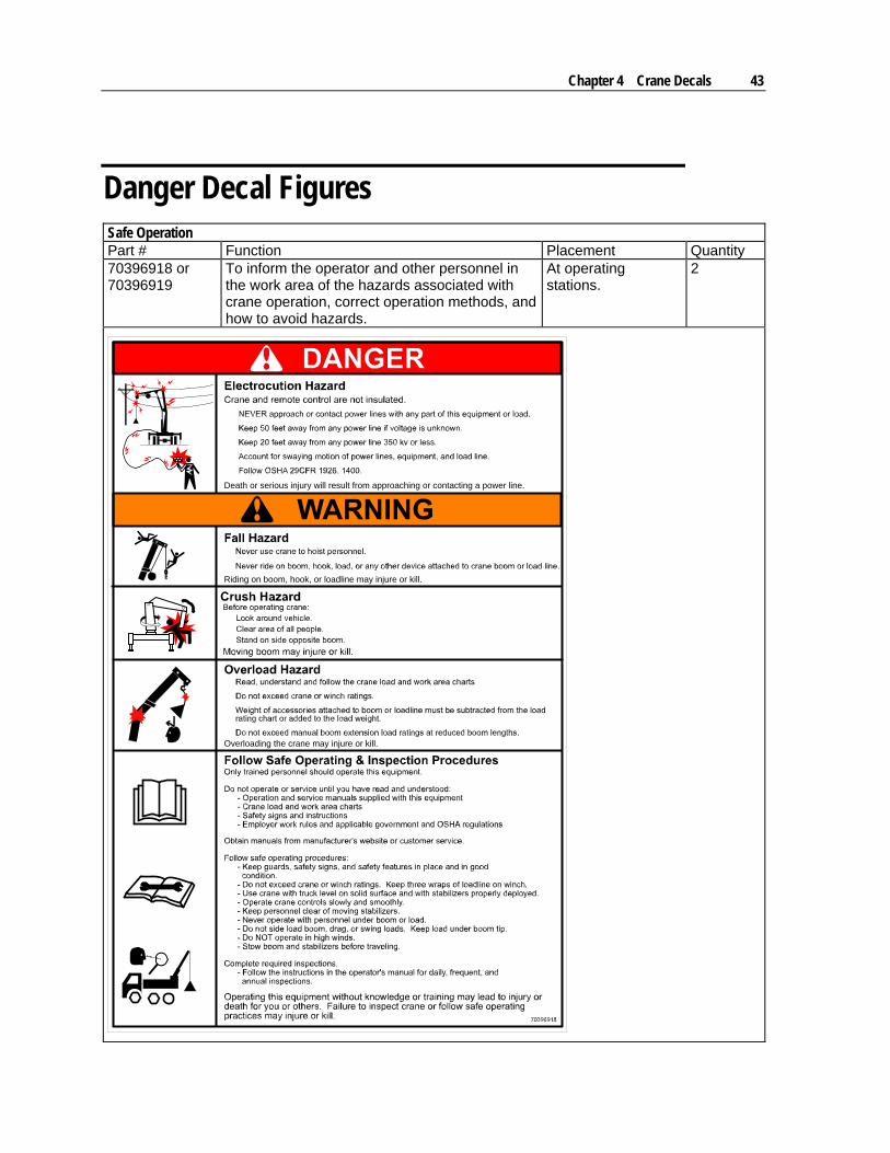
Danger Decal Figures Safe Operation Part # Function Placement Quantity 70396918 or 70396919
To inform the operator and other personnel in the work area of the hazards associated with crane operation, correct operation methods, and how to avoid hazards.
At operating stations.
2
Death or serious injury will result from approaching or contacting a power line.
Riding on boom, hook, or loadline may injure or kill.
Overloading the crane may injure or kill.
44 Material Handling Crane Operation & Safety Manual # 99904591
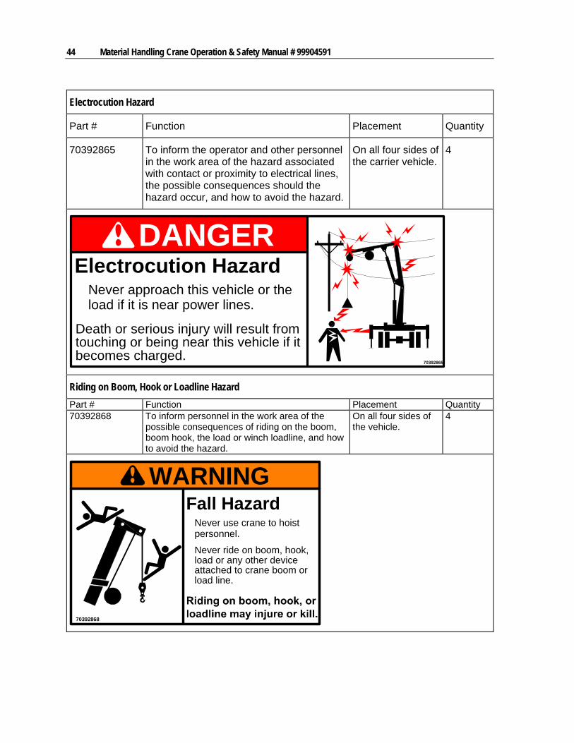
Electrocution Hazard
Part # Function Placement Quantity
70392865 To inform the operator and other personnel in the work area of the hazard associated with contact or proximity to electrical lines, the possible consequences should the hazard occur, and how to avoid the hazard.
On all four sides of the carrier vehicle.
4
70392865
DANGERElectrocution Hazard
Never approach this vehicle or theload if it is near power lines.
Death or serious injury will result fromtouching or being near this vehicle if itbecomes charged.
Riding on Boom, Hook or Loadline Hazard
Part # Function Placement Quantity 70392868 To inform personnel in the work area of the
possible consequences of riding on the boom, boom hook, the load or winch loadline, and how to avoid the hazard.
On all four sides of the vehicle.
4
WARNING
70392868
Fall HazardNever use crane to hoistpersonnel.
Never ride on boom, hook,load or any other deviceattached to crane boom orload line.
Chapter 4 Crane Decals 45
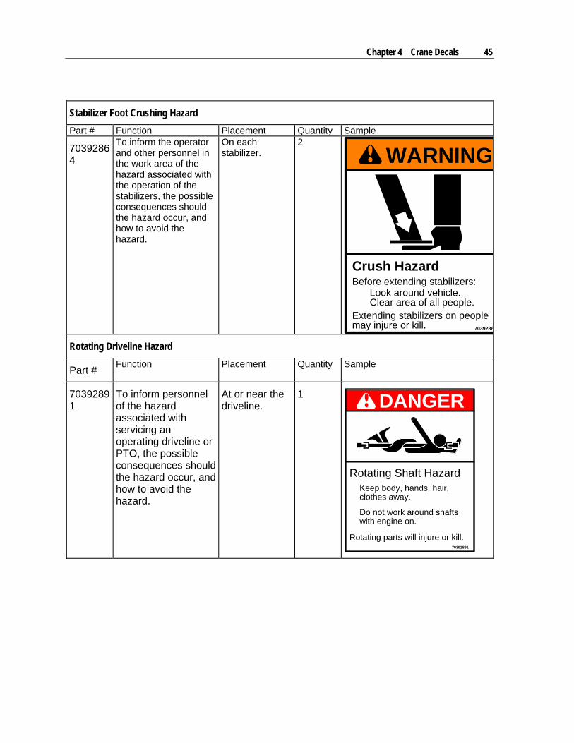
Stabilizer Foot Crushing Hazard
Part # Function Placement Quantity Sample
70392864
To inform the operator and other personnel in the work area of the hazard associated with the operation of the stabilizers, the possible consequences should the hazard occur, and how to avoid the hazard.
On each stabilizer.
2
WARNING
7039286
Crush HazardBefore extending stabilizers:
Look around vehicle.Clear area of all people.
Extending stabilizers on peoplemay injure or kill.
Rotating Driveline Hazard
Part # Function Placement Quantity Sample
70392891
To inform personnel of the hazard associated with servicing an operating driveline or PTO, the possible consequences should the hazard occur, and how to avoid the hazard.
At or near the driveline.
1 DANGER
70392891
Rotating Shaft Hazard
Rotating parts will injure or kill.
Do not work around shafts
Keep body, hands, hair,clothes away.
with engine on.
46 Material Handling Crane Operation & Safety Manual # 99904591
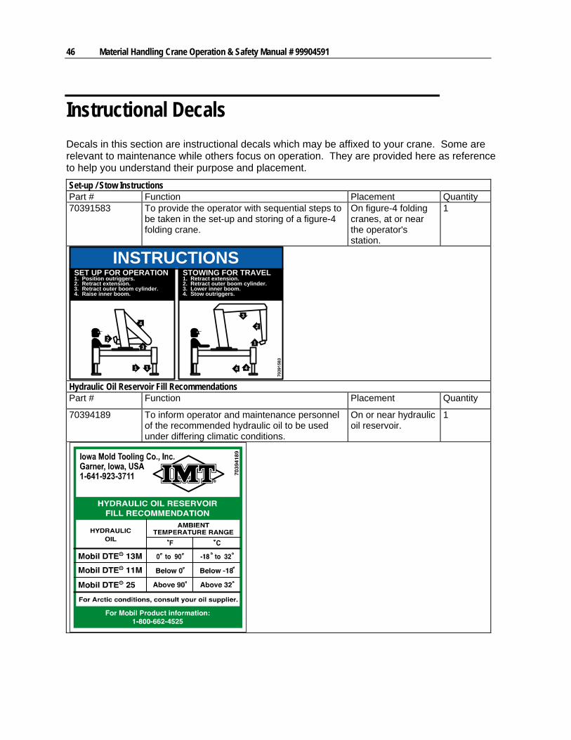
Instructional Decals
Decals in this section are instructional decals which may be affixed to your crane. Some are relevant to maintenance while others focus on operation. They are provided here as reference to help you understand their purpose and placement.
Set-up / Stow Instructions Part # Function Placement Quantity 70391583 To provide the operator with sequential steps to
be taken in the set-up and storing of a figure-4 folding crane.
On figure-4 folding cranes, at or near the operator's station.
1
SET UP FOR OPERATION1. Position outriggers.2. Retract extension.3. Retract outer boom cylinder.4. Raise inner boom.
STOWING FOR TRAVEL1. Retract extension.2. Retract outer boom cylinder.3. Lower inner boom.4. Stow outriggers.
1
1
44
2
3
1
2
4
3
INSTRUCTIONS
Hydraulic Oil Reservoir Fill Recommendations Part # Function Placement Quantity
70394189 To inform operator and maintenance personnel of the recommended hydraulic oil to be used under differing climatic conditions.
On or near hydraulic oil reservoir.
1
Chapter 4 Crane Decals 47
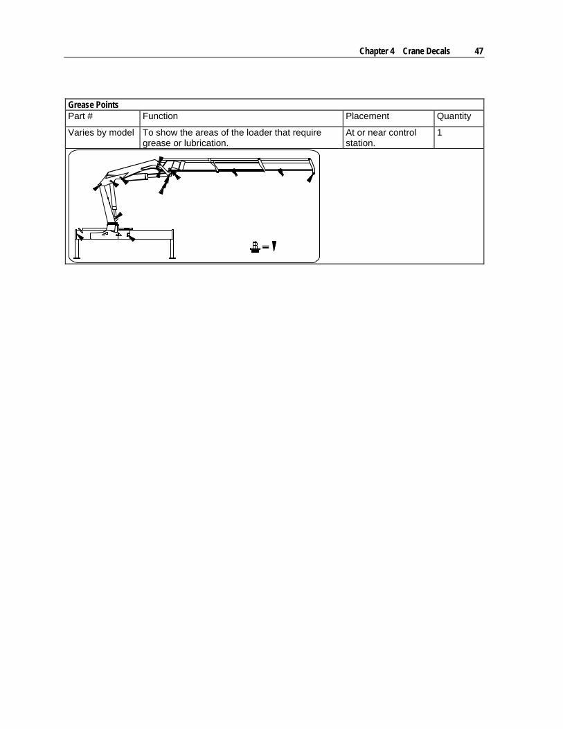
Grease Points Part # Function Placement Quantity
Varies by model To show the areas of the loader that require grease or lubrication.
At or near control station.
1


49
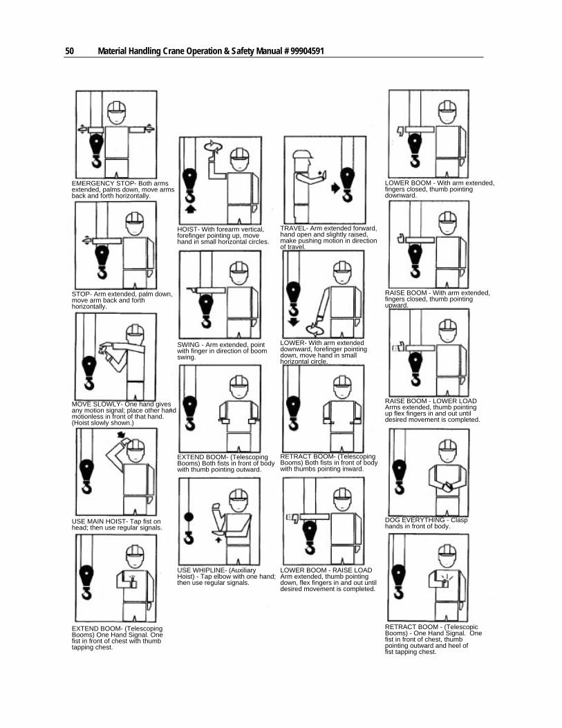
Hand signals can be used to communicate between crane operators and assistants when the job site noise level is too high to communicate in other ways.
Signals to the operator shall follow ASME B30.5 standards, unless voice communication is utilized. Signals shall be discernible or audible at all times. No response by the operator is to be made unless the signal is clearly understood.
For operations not covered by the ASME hand signals, additions to or modifications may be made. These special signals must be agreed upon by the operator and signal person before the crane is operated.
If verbal instructions are required rather than hand signals, all crane motions must be stopped before doing so. Figure includes an illustration of the hand signal, the operation associated with the signal, and a description of the signal. The operator and signal person must review these signals and agree to their use before implementation. For complete hand signal information, refer to ASME/ANSI B30.5 - Mobile and Locomotive Cranes, published by the American Society of Mechanical Engineers.
The hand signals presented by The American Society of Mechanical Engineers have been accepted by the Occupational Safety and Health Administration (OSHA).
C H A P T E R 5
Hand Signals
50 Material Handling Crane Operation & Safety Manual # 99904591
EMERGENCY STOP- Both armsextended, palms down, move armsback and forth horizontally.
STOP- Arm extended, palm down,move arm back and forthhorizontally.
MOVE SLOWLY- One hand givesany motion signal; place other handmotionless in front of that hand.(Hoist slowly shown.)
USE MAIN HOIST- Tap fist onhead; then use regular signals.
EXTEND BOOM- (TelescopingBooms) One Hand Signal. Onefist in front of chest with thumbtapping chest.
USE WHIPLINE- (AuxiliaryHoist) - Tap elbow with one hand;then use regular signals.
SWING - Arm extended, pointwith finger in direction of boomswing.
EXTEND BOOM- (TelescopingBooms) Both fists in front of bodywith thumb pointing outward.
HOIST- With forearm vertical,forefinger pointing up, movehand in small horizontal circles.
TRAVEL- Arm extended forward,hand open and slightly raised,make pushing motion in directionof travel.
LOWER- With arm extendeddownward, forefinger pointingdown, move hand in smallhorizontal circle.
RETRACT BOOM- (TelescopingBooms) Both fists in front of bodywith thumbs pointing inward.
LOWER BOOM - RAISE LOADArm extended, thumb pointingdown, flex fingers in and out untildesired movement is completed.
RETRACT BOOM - (TelescopicBooms) - One Hand Signal. Onefist in front of chest, thumbpointing outward and heel offist tapping chest.
DOG EVERYTHING - Clasphands in front of body.
RAISE BOOM - LOWER LOADArms extended, thumb pointingup flex fingers in and out untildesired movement is completed.
RAISE BOOM - With arm extended,fingers closed, thumb pointingupward.
LOWER BOOM - With arm extended,fingers closed, thumb pointingdownward.
51
In This Chapter
Winch Safety ..............................................................................51 Winch Mount - Outer Boom........................................................51 Winch Mount - Fly-Jib.................................................................52 Winch Mount - Inner Boom.........................................................54 Winch Installation on Boom System...........................................56 Fly-Jib.........................................................................................58 Fly-Jib Safety..............................................................................61
Winch Safety The loader safety system prevents the loader and winch system from being overloaded, but
the operator is ultimately responsible for safe loader / winch operation.
Do not try to lift a load that exceeds the winch hook capacity, noted with a label on the swivel hook. The label indicates the maximum wire stress on the wire.
Operate the winch slowly and smoothly. Ensure the wire is correctly wound.
Do not sideload the winch. Only lift vertically with the winch.
Never drag a load across a surface. The winch is designed for vertical lifts.
Keep the wire taut when working with a winch. Stop the winch down movement as soon as the load is placed on the surface.
Always operate the winch up movement carefully when the hook reaches the hoist stop.
Do not operate the winch quickly when working with a load hanging on a long winch cable. Do not swing the load on the winch cable.
Raise and lower the winch cable slowly when working in high positions with loader and Fly-Jib, if any.
Extend the outer boom extensions to the position where the winch is required, prior to using the winch. Do not extend loader and fly-jib extensions with a load on the winch cable.
If the safety system stops the loader or winch function, immediately investigate the cause.
C H A P T E R 6
Component Installation
52 Material Handling Crane Operation & Safety Manual # 99904591
Winch Mount - Outer Boom
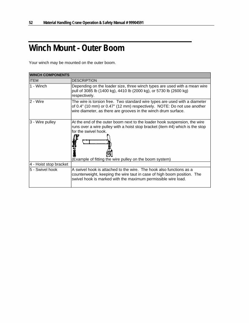
Your winch may be mounted on the outer boom.
WINCH COMPONENTS
ITEM DESCRIPTION
1 - Winch Depending on the loader size, three winch types are used with a mean wire pull of 3085 lb (1400 kg), 4410 lb (2000 kg), or 5730 lb (2600 kg) respectively.
2 - Wire The wire is torsion free. Two standard wire types are used with a diameter of 0.4" (10 mm) or 0.47" (12 mm) respectively. NOTE: Do not use another wire diameter, as there are grooves in the winch drum surface.
3 - Wire pulley At the end of the outer boom next to the loader hook suspension, the wire runs over a wire pulley with a hoist stop bracket (item #4) which is the stop for the swivel hook.
(Example of fitting the wire pulley on the boom system)
4 - Hoist stop bracket 5 - Swivel hook A swivel hook is attached to the wire. The hook also functions as a
counterweight, keeping the wire taut in case of high boom position. The swivel hook is marked with the maximum permissible wire load.
Chapter 6 Component Installation 53
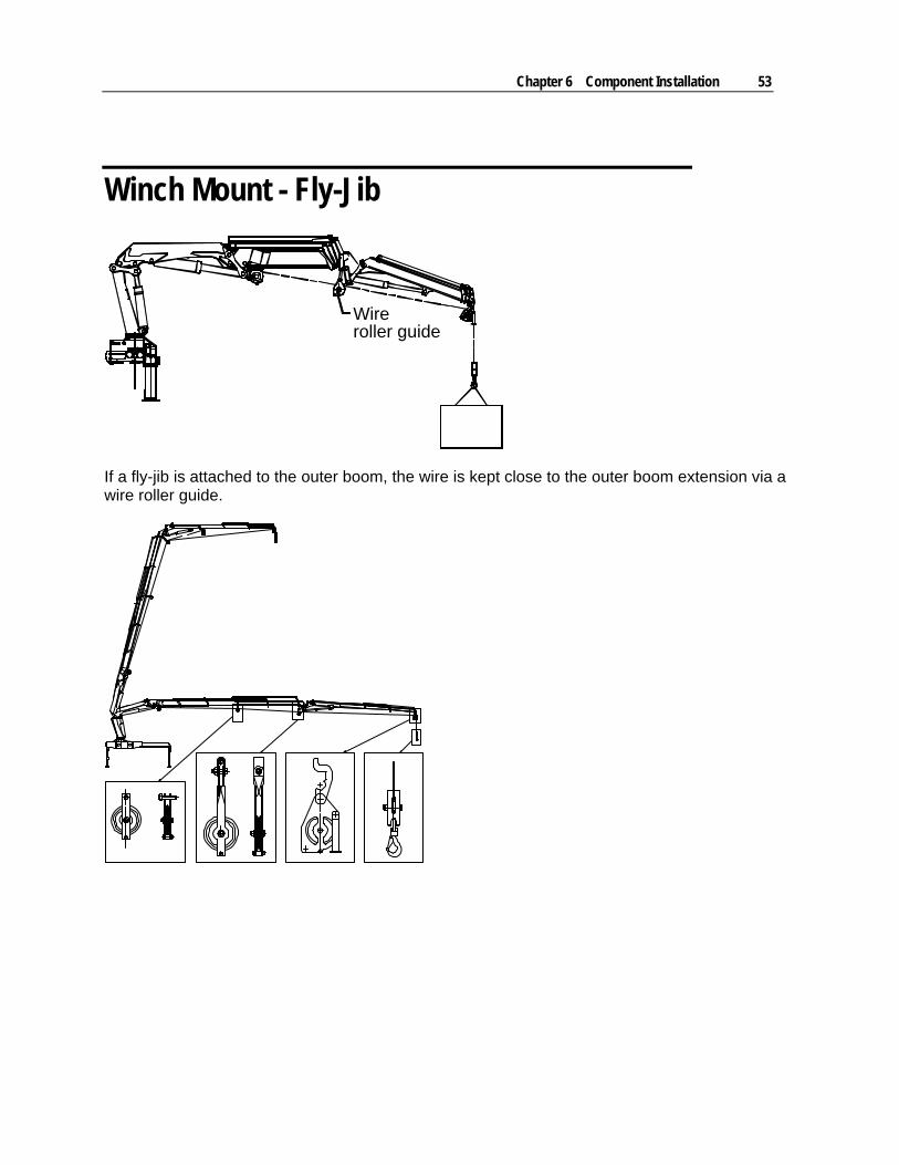
Winch Mount - Fly-Jib
Wireroller guide
If a fly-jib is attached to the outer boom, the wire is kept close to the outer boom extension via a wire roller guide.
54 Material Handling Crane Operation & Safety Manual # 99904591
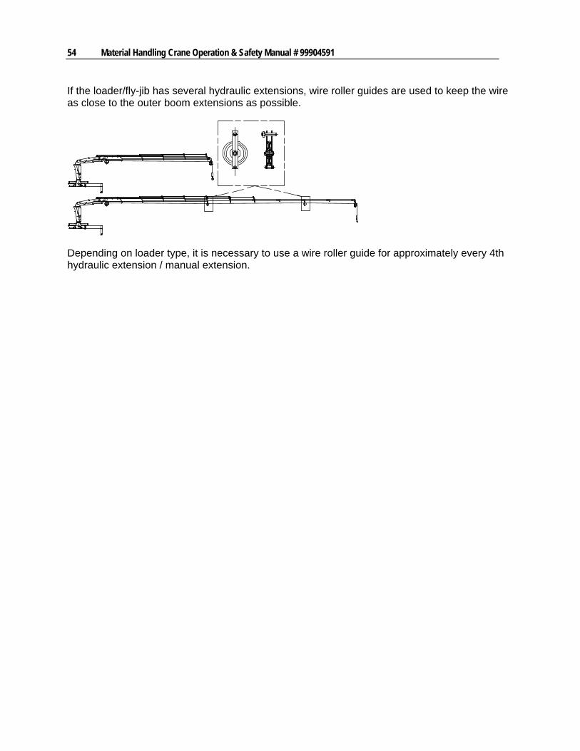
If the loader/fly-jib has several hydraulic extensions, wire roller guides are used to keep the wire as close to the outer boom extensions as possible.
Depending on loader type, it is necessary to use a wire roller guide for approximately every 4th hydraulic extension / manual extension.
Chapter 6 Component Installation 55
Winch Mount - Inner Boom
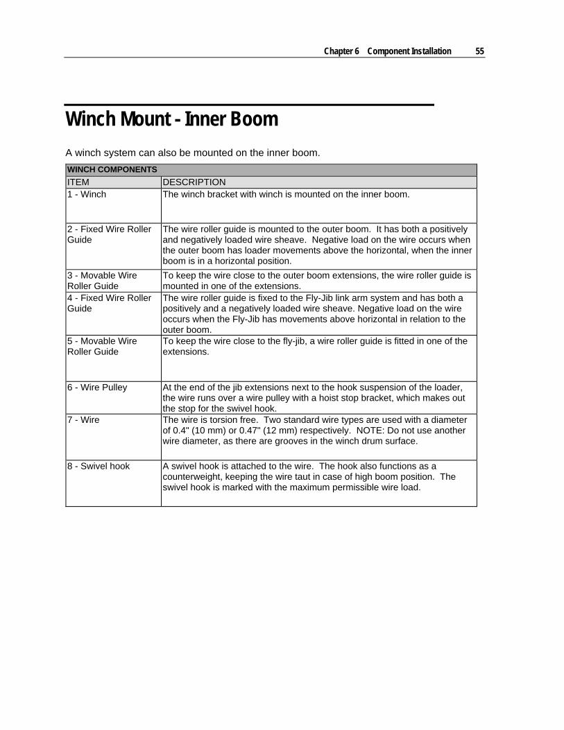
A winch system can also be mounted on the inner boom.
WINCH COMPONENTS
ITEM DESCRIPTION 1 - Winch The winch bracket with winch is mounted on the inner boom.
2 - Fixed Wire Roller Guide
The wire roller guide is mounted to the outer boom. It has both a positively and negatively loaded wire sheave. Negative load on the wire occurs when the outer boom has loader movements above the horizontal, when the inner boom is in a horizontal position.
3 - Movable Wire Roller Guide
To keep the wire close to the outer boom extensions, the wire roller guide is mounted in one of the extensions.
4 - Fixed Wire Roller Guide
The wire roller guide is fixed to the Fly-Jib link arm system and has both a positively and a negatively loaded wire sheave. Negative load on the wire occurs when the Fly-Jib has movements above horizontal in relation to the outer boom.
5 - Movable Wire Roller Guide
To keep the wire close to the fly-jib, a wire roller guide is fitted in one of the extensions.
6 - Wire Pulley At the end of the jib extensions next to the hook suspension of the loader, the wire runs over a wire pulley with a hoist stop bracket, which makes out the stop for the swivel hook.
7 - Wire The wire is torsion free. Two standard wire types are used with a diameter of 0.4" (10 mm) or 0.47" (12 mm) respectively. NOTE: Do not use another wire diameter, as there are grooves in the winch drum surface.
8 - Swivel hook A swivel hook is attached to the wire. The hook also functions as a counterweight, keeping the wire taut in case of high boom position. The swivel hook is marked with the maximum permissible wire load.
56 Material Handling Crane Operation & Safety Manual # 99904591
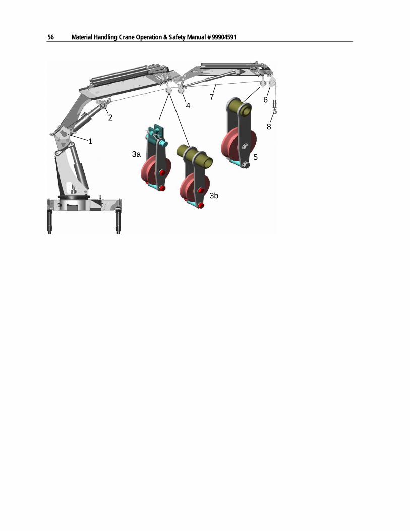
1
2
3a
3b
5
47
8
6
Chapter 6 Component Installation 57
Winch Installation on Boom System
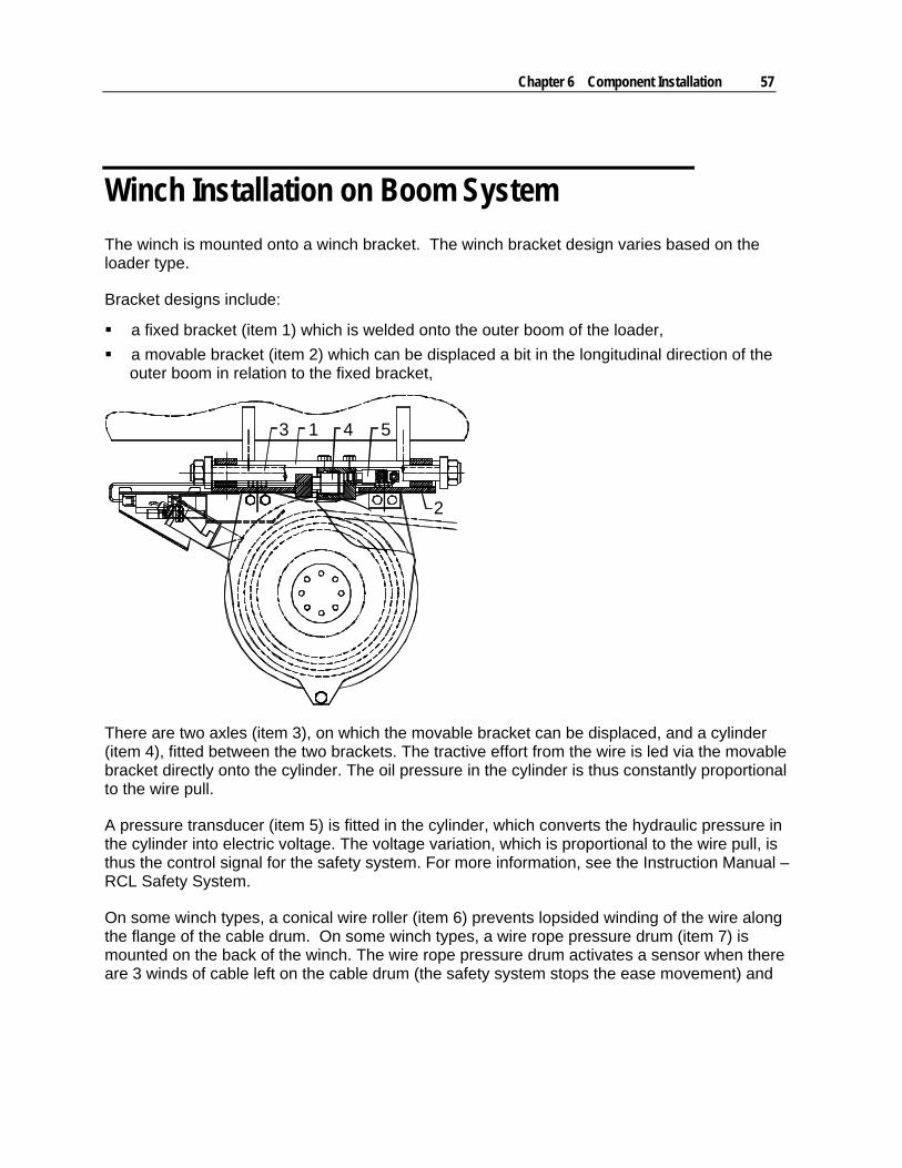
The winch is mounted onto a winch bracket. The winch bracket design varies based on the loader type.
Bracket designs include:
a fixed bracket (item 1) which is welded onto the outer boom of the loader,
a movable bracket (item 2) which can be displaced a bit in the longitudinal direction of the outer boom in relation to the fixed bracket,
3 1 4 5
2
There are two axles (item 3), on which the movable bracket can be displaced, and a cylinder (item 4), fitted between the two brackets. The tractive effort from the wire is led via the movable bracket directly onto the cylinder. The oil pressure in the cylinder is thus constantly proportional to the wire pull.
A pressure transducer (item 5) is fitted in the cylinder, which converts the hydraulic pressure in the cylinder into electric voltage. The voltage variation, which is proportional to the wire pull, is thus the control signal for the safety system. For more information, see the Instruction Manual – RCL Safety System.
On some winch types, a conical wire roller (item 6) prevents lopsided winding of the wire along the flange of the cable drum. On some winch types, a wire rope pressure drum (item 7) is mounted on the back of the winch. The wire rope pressure drum activates a sensor when there are 3 winds of cable left on the cable drum (the safety system stops the ease movement) and
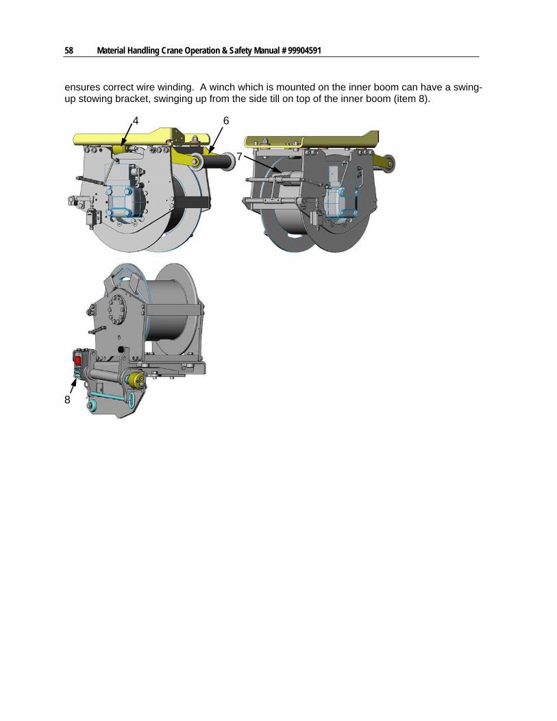
58 Material Handling Crane Operation & Safety Manual # 99904591
ensures correct wire winding. A winch which is mounted on the inner boom can have a swing-up stowing bracket, swinging up from the side till on top of the inner boom (item 8).
4 6
7
8
Chapter 6 Component Installation 59
Fly-Jib
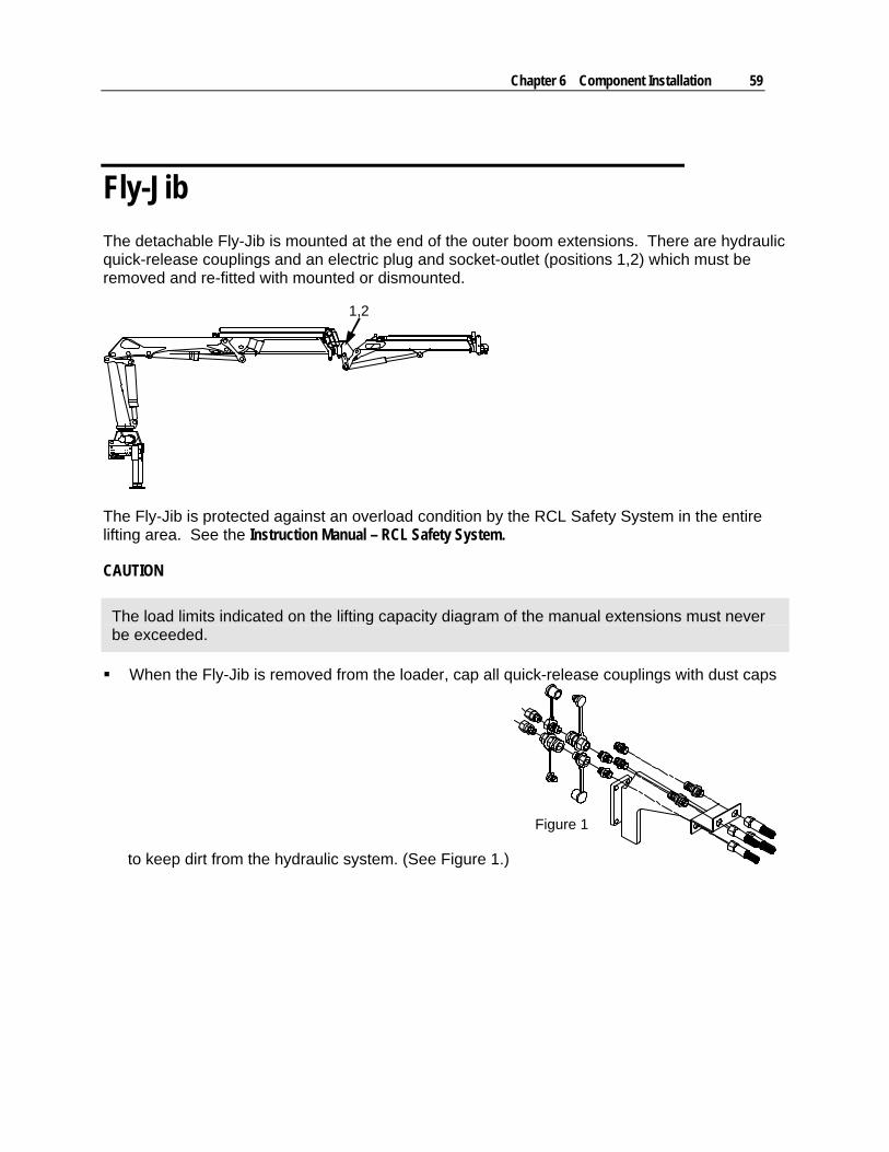
The detachable Fly-Jib is mounted at the end of the outer boom extensions. There are hydraulic quick-release couplings and an electric plug and socket-outlet (positions 1,2) which must be removed and re-fitted with mounted or dismounted.
1,2
The Fly-Jib is protected against an overload condition by the RCL Safety System in the entire lifting area. See the Instruction Manual – RCL Safety System.
CAUTION
The load limits indicated on the lifting capacity diagram of the manual extensions must never be exceeded.
When the Fly-Jib is removed from the loader, cap all quick-release couplings with dust caps
to keep dirt from the hydraulic system. (See Figure 1.)
Figure 1
60 Material Handling Crane Operation & Safety Manual # 99904591
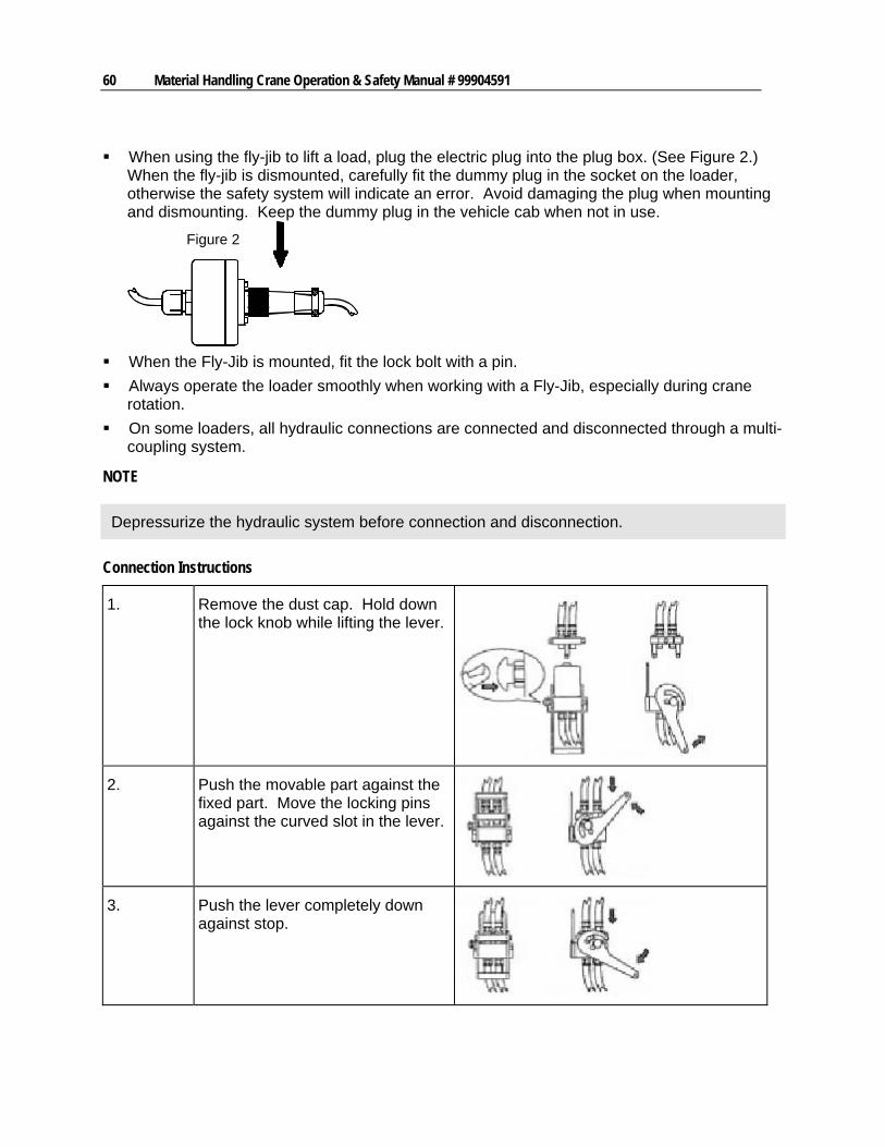
When using the fly-jib to lift a load, plug the electric plug into the plug box. (See Figure 2.) When the fly-jib is dismounted, carefully fit the dummy plug in the socket on the loader, otherwise the safety system will indicate an error. Avoid damaging the plug when mounting and dismounting. Keep the dummy plug in the vehicle cab when not in use.
Figure 2
When the Fly-Jib is mounted, fit the lock bolt with a pin.
Always operate the loader smoothly when working with a Fly-Jib, especially during crane rotation.
On some loaders, all hydraulic connections are connected and disconnected through a multi-coupling system.
NOTE
Depressurize the hydraulic system before connection and disconnection.
Connection Instructions
1. Remove the dust cap. Hold down the lock knob while lifting the lever.
2. Push the movable part against the fixed part. Move the locking pins against the curved slot in the lever.
3. Push the lever completely down against stop.
Chapter 6 Component Installation 61
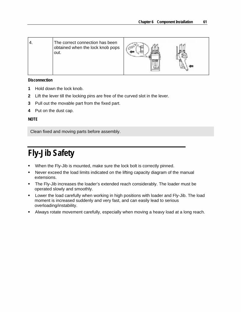
4. The correct connection has been obtained when the lock knob pops out.
Disconnection
1 Hold down the lock knob.
2 Lift the lever till the locking pins are free of the curved slot in the lever.
3 Pull out the movable part from the fixed part.
4 Put on the dust cap.
NOTE
Clean fixed and moving parts before assembly.
Fly-Jib Safety When the Fly-Jib is mounted, make sure the lock bolt is correctly pinned.
Never exceed the load limits indicated on the lifting capacity diagram of the manual extensions.
The Fly-Jib increases the loader’s extended reach considerably. The loader must be operated slowly and smoothly.
Lower the load carefully when working in high positions with loader and Fly-Jib. The load moment is increased suddenly and very fast, and can easily lead to serious overloading/instability.
Always rotate movement carefully, especially when moving a heavy load at a long reach.

63
In This Chapter
Wire Rope Inspection .................................................................63 Wire Rope Lubrication................................................................64 Wire Rope Inspection & Replacement .......................................64 Wire Rope Slings........................................................................66 Basic Hitches..............................................................................67 Sling Loading..............................................................................68 Hooks .........................................................................................68 Methods of Hook Inspection.......................................................69 Hook Testing ..............................................................................71
Wire Rope Inspection
OSHA requires regular inspections and permanent, signed record-keeping on wire rope inspections. These inspections help the crane operator determine whether the rope can be safely used. Inspection criteria, including number and location of broken wires, wear and elongation, have been established by OSHA, ANSI, ASME and similar organizations.
WIRE ROPE INSPECTION CRITERIA
1 INSPECTOR - The wire rope inspector must keep written reports of the rope condition on file at the work site and must have the authority to order wire rope replacements and keep unsafe wire rope from being used.
2 PERIODS OF INSPECTION - Set up inspection periods for each material hoist wire rope. Determine inspection frequency by considering environment, degree of hazard to materials, frequency of operation and the frequency with which the wire rope is subjected to its capacity limits. Inspect at least every 30 days.
3 METHODS OF INSPECTION - To inspect, unwind the working length of the wire rope from the hoist drum. Thoroughly inspect the rope sections that pass over sheaves, drums or contact saddles or which make opposing turns. Inspect the rope close to the end attachments. DO NOT open the rope for inspection.
4 USED WIRE ROPE - Thoroughly inspect used wire rope prior to installation.
5 IDLE EQUIPMENT - Inspect wire rope on idle equipment prior to operation.
C H A P T E R 7
Wire Rope & Hooks
64 Material Handling Crane Operation & Safety Manual # 99904591
DAILY INSPECTION: Inspect for kinking (sharp bends), crushing, unstranding, birdcaging, core protrusion, rope diameter loss, rope strand unevenness, general corrosion, broken or cut strands, heat damage, and integrity of end attachments.
MONTHLY INSPECTION: Each month, inspect the entire length of the rope, the wire rope eye, and the sheaves, drums and other apparatus with which the rope makes contact.
When a wire rope has been removed from service because it is no longer suitable for use, it must not be re-used on another application. Every wire rope user should understand that each type of fitting attached to a wire rope has a specific efficiency rating which can reduce the working load of the rope assembly or rope system, and this must be given due consideration in determining the capacity of a wire rope system.
Wire Rope Lubrication
Wire rope used on IMT cranes does not have continuous lubrication replenishment. Use open gear lubricant to protect the wire rope on your crane. The areas of rope which experience the most wear are located over sheaves or are otherwise hidden, and these areas require the most rope lubrication.
Lubricate the wire rope using ChainMate™ Chain and Wire Rope lubricant, Vitalife® 400, or equivalent. To lubricate the rope:
1 Clean dirt, dust, and foreign matter from the rope.
2 Apply ChainMate lubricant or equivalent, penetrating the strands of the rope. Apply according to the lubricant specifications.
3 Apply lubricant heavily to portions which encounter bending such as at the sheave and winch.
Wire Rope Inspection & Replacement
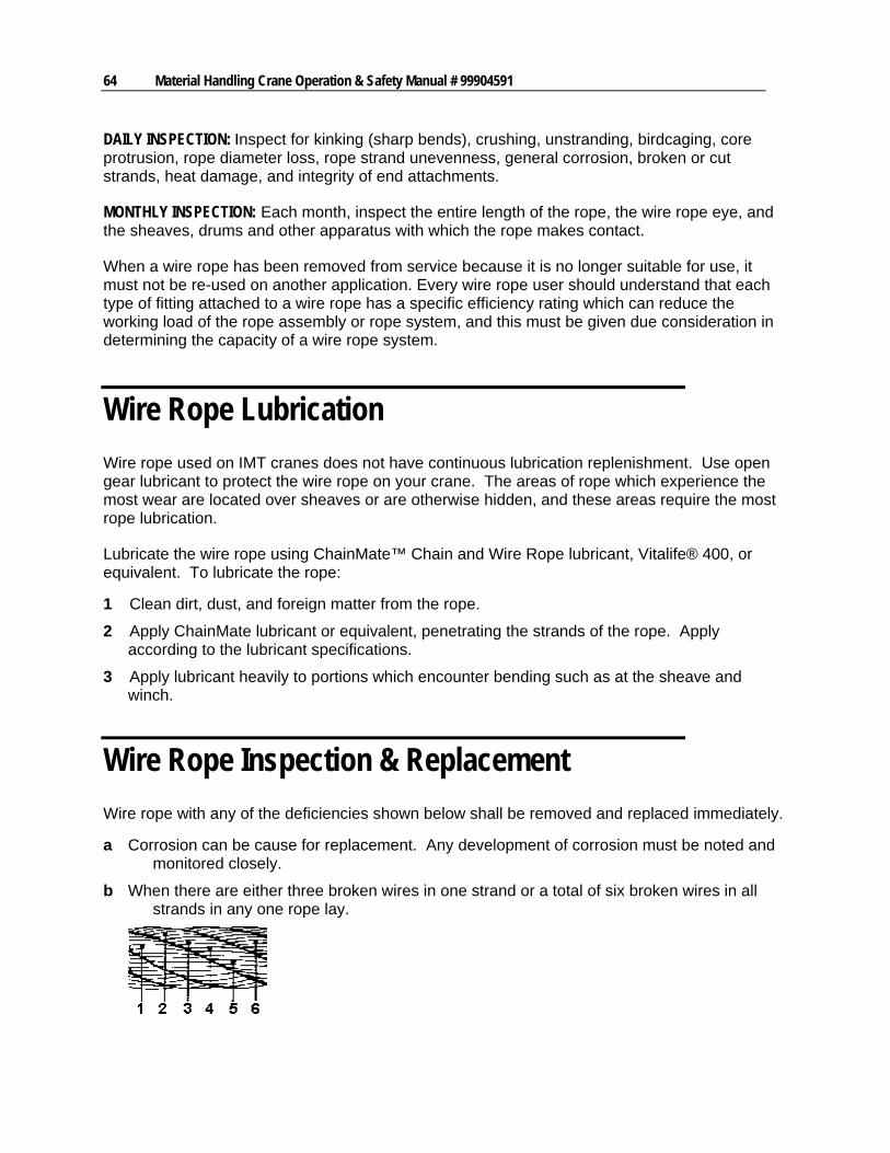
Wire rope with any of the deficiencies shown below shall be removed and replaced immediately.
a Corrosion can be cause for replacement. Any development of corrosion must be noted and monitored closely.
b When there are either three broken wires in one strand or a total of six broken wires in all strands in any one rope lay.
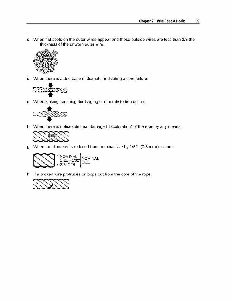
Chapter 7 Wire Rope & Hooks 65
c When flat spots on the outer wires appear and those outside wires are less than 2/3 the thickness of the unworn outer wire.
d When there is a decrease of diameter indicating a core failure.
e When kinking, crushing, birdcaging or other distortion occurs.
f When there is noticeable heat damage (discoloration) of the rope by any means.
g When the diameter is reduced from nominal size by 1/32" (0.8 mm) or more.
NOMINALSIZE - 1/32"(0.8 mm)
NOMINALSIZE
h If a broken wire protrudes or loops out from the core of the rope.
66 Material Handling Crane Operation & Safety Manual # 99904591
Wire Rope Slings
Rated load (rated capacity) of a wire rope sling is based on the nominal, or catalog strength of the wire rope used in the sling, and factors which affect the overall strength of the sling. These factors include attachment or splicing efficiency, the number of parts of rope in the sling, type of hitch (straight, choker, basket), diameter around which the body of the sling is bent, and the diameter of hook over which the eye of the sling is rigged. Rated load of a sling is different for each of the three basic methods of rigging. These rated loads are available from your wire rope sling supplier and may be indicated on a tag attached to the sling at the time it is fabricated.
WARNING
A HAND-TUCKED EYE SPLICE CAN UNLAY (UNRAVEL) AND FAIL IF THE SLING IS ALLOWED TO ROTATE DURING USE.
Never shock load a sling. There is no practical way to estimate the actual force applied by shock loading. The rated load of a wire rope sling can easily be exceeded by a sudden application of force, and damage can occur to the sling. The sudden release of a load can also damage a sling.
Protect the body of a wire rope sling using corner protectors, blocking or padding against damage by sharp edges or corners of a load being lifted. Sharp bends that distort the sling body damage the wire rope and reduce its strength.
Any angle other than vertical at which a sling is rigged increases the loading on the sling.
Visually inspect a sling before each lift or usage to determine if it is capable of safely making the intended lift in the same method as inspecting a wire rope.
If a sling is found to be deficient, the eyes must be cut, or other end attachments or fittings removed to prevent further use, and the sling body discarded.
Never use a sling eye over a hook or pin with a body diameter larger than the natural width of the eye. Never force an eye onto a hook. The eye should always be used on a hook or pin with at least the diameter of the rope.
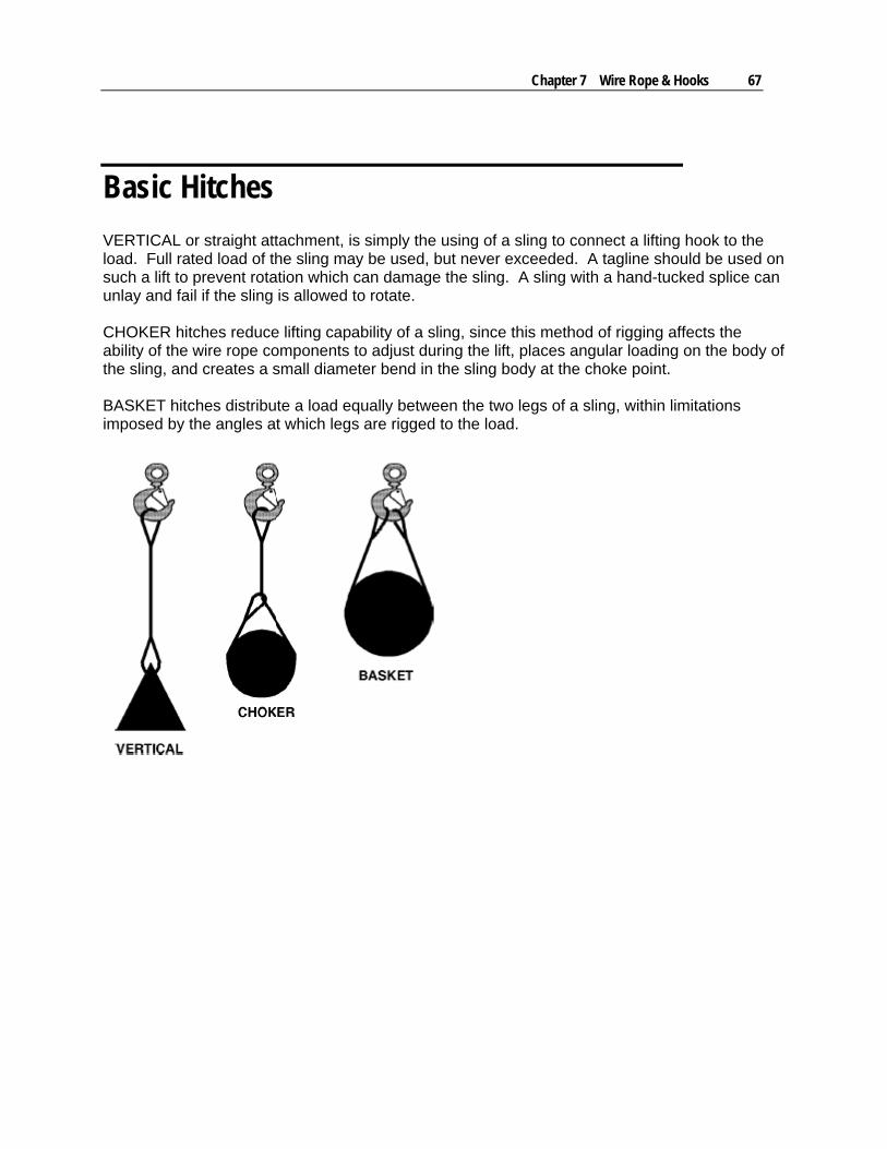
Chapter 7 Wire Rope & Hooks 67
Basic Hitches
VERTICAL or straight attachment, is simply the using of a sling to connect a lifting hook to the load. Full rated load of the sling may be used, but never exceeded. A tagline should be used on such a lift to prevent rotation which can damage the sling. A sling with a hand-tucked splice can unlay and fail if the sling is allowed to rotate. CHOKER hitches reduce lifting capability of a sling, since this method of rigging affects the ability of the wire rope components to adjust during the lift, places angular loading on the body of the sling, and creates a small diameter bend in the sling body at the choke point. BASKET hitches distribute a load equally between the two legs of a sling, within limitations imposed by the angles at which legs are rigged to the load.
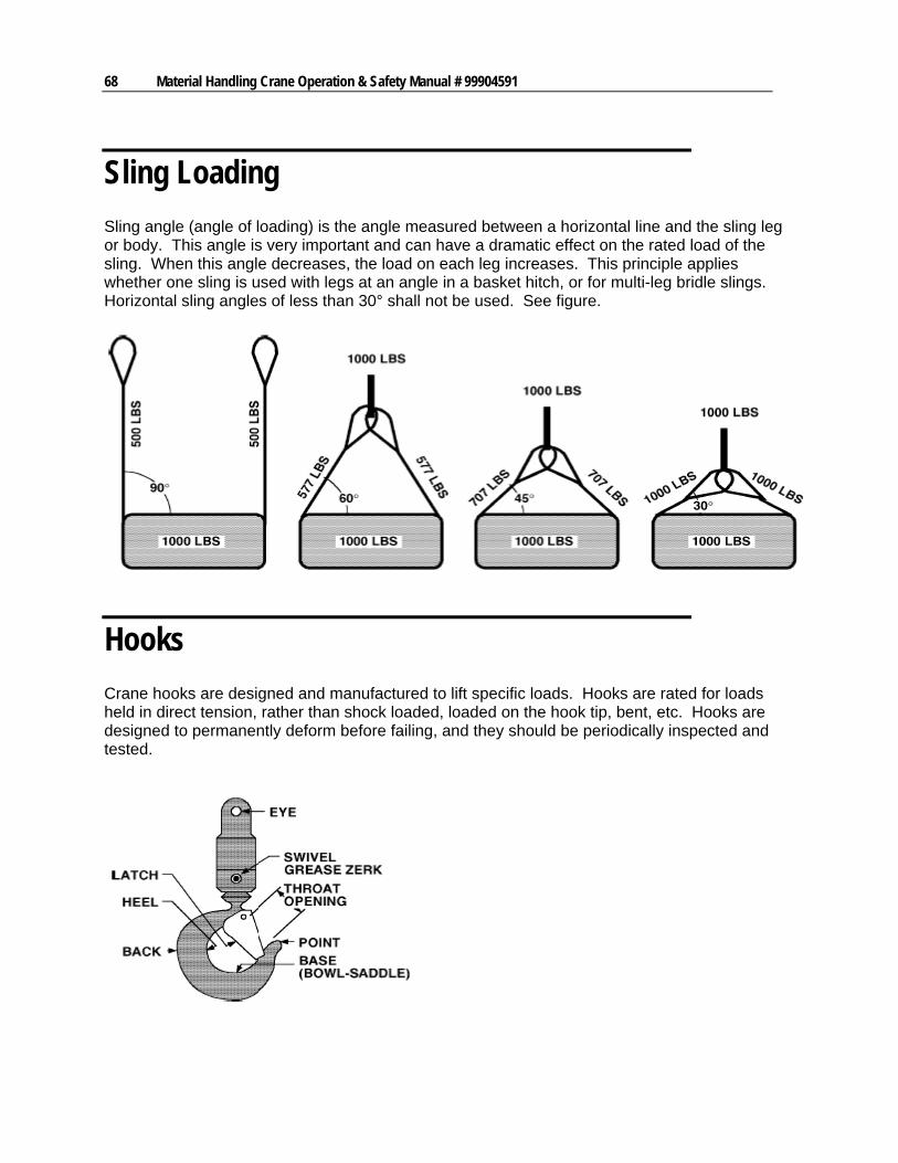
68 Material Handling Crane Operation & Safety Manual # 99904591
Sling Loading
Sling angle (angle of loading) is the angle measured between a horizontal line and the sling leg or body. This angle is very important and can have a dramatic effect on the rated load of the sling. When this angle decreases, the load on each leg increases. This principle applies whether one sling is used with legs at an angle in a basket hitch, or for multi-leg bridle slings. Horizontal sling angles of less than 30° shall not be used. See figure.
Hooks
Crane hooks are designed and manufactured to lift specific loads. Hooks are rated for loads held in direct tension, rather than shock loaded, loaded on the hook tip, bent, etc. Hooks are designed to permanently deform before failing, and they should be periodically inspected and tested.
Chapter 7 Wire Rope & Hooks 69
LATCHES
Use a hook equipped with a latch except when a latch is impractical or dangerous. The latch is used to retain such items as slings and chains under slack conditions. Latches do not support loads, and should not be crowded by oversized rope or stiff riggings. The load should be seated on the “bowl-saddle” before lifting.
HOOK SWIVELS
Hook swivels prevent a load from twisting caused by a natural tendency for wire rope to unwind under load. These swivels, usually a part of the hook, are fitted with bearings to provide for rotation. Regular lubrication of the swivel bearings is extremely important and is normally applied by way of a grease zerk located on the swivel.
CAUTION
THE CRIMPING EFFECT OF WEDGE SOCKETS CAN REDUCE THE SAFE WORKING LIMIT OF A LINE BY AS MUCH AS 30%
Methods of Hook Inspection
Inspections and record keeping requirements for hooks are determined by the kind of equipment the hooks are used on. When the inspection requirements for hooks are specified in regulations applicable to your equipment, those regulations will take precedence over the information presented here.
NEW AND REPAIRED HOOKS
NEW AND REPAIRED HOOKSPrior to initial use, inspect all new and repaired hooks shall to assure compliance with the items listed in the HOOK INSPECTION CHECKLIST.
HOOKS IN REGULAR USE
Inspect hooks in regular use with the FREQUENT or PERIODIC method as described below.
70 Material Handling Crane Operation & Safety Manual # 99904591
HOOKS NOT IN REGULAR USE
Hooks not in regular use should be inspected before they are returned to service. See HOOK INSPECTION CHECKLIST.
REQUIREMENTS FREQUENT INSPECTION PERIODIC INSPECTION MEANS Visual examination by the
operator or designated person. Visual inspections by an appointed person.
RECORDS Records of the inspection are not required.
Records of apparent external hook conditions should be created to provide the basis for continuing hook evaluation.
NORMAL SERVICE (Less than 85% of rated load except for isolated instances.)
Monthly Yearly
HEAVY SERVICE (85% to 100% of rated load on a regular basis.)
Weekly to Monthly Yearly, unless hook conditions indicate a need for detailed inspection.
SEVERE SERVICE (85% to 100% of rated load regularly and under environmental conditions which are unfavorable, harmful, or detrimental to the hook.)
Daily to Weekly Quarterly, as above, unless detailed inspection shows a need for non-destructive testing.
SPECIAL or INFREQUENT SERVICE
As authorized by a qualified person, and before and after each period of service, with record of the operation retained.
As authorized by a qualified person, before the first period of service, and as directed by the qualified person for any subsequent operation.
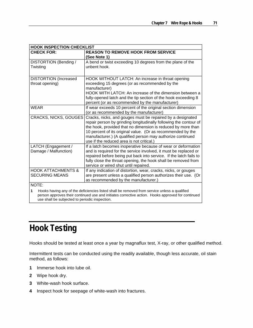
Chapter 7 Wire Rope & Hooks 71
HOOK INSPECTION CHECKLIST CHECK FOR: REASON TO REMOVE HOOK FROM SERVICE
(See Note 1) DISTORTION (Bending / Twisting
A bend or twist exceeding 10 degrees from the plane of the unbent hook.
DISTORTION (Increased throat opening)
HOOK WITHOUT LATCH: An increase in throat opening exceeding 15 degrees (or as recommended by the manufacturer) HOOK WITH LATCH: An increase of the dimension between a fully-opened latch and the tip section of the hook exceeding 8 percent (or as recommended by the manufacturer)
WEAR If wear exceeds 10 percent of the original section dimension (or as recommended by the manufacturer)
CRACKS, NICKS, GOUGES Cracks, nicks, and gouges must be repaired by a designated repair person by grinding longitudinally following the contour of the hook, provided that no dimension is reduced by more than 10 percent of its original value. (Or as recommended by the manufacturer.) (A qualified person may authorize continued use if the reduced area is not critical.)
LATCH (Engagement / Damage / Malfunction)
If a latch becomes inoperative because of wear or deformation and is required for the service involved, it must be replaced or repaired before being put back into service. If the latch fails to fully close the throat opening, the hook shall be removed from service or wired shut until repaired.
HOOK ATTACHMENTS & SECURING MEANS
If any indication of distortion, wear, cracks, nicks, or gouges are present unless a qualified person authorizes their use. (Or as recommended by the manufacturer.)
NOTE: 1 Hooks having any of the deficiencies listed shall be removed from service unless a qualified
person approves their continued use and initiates corrective action. Hooks approved for continued use shall be subjected to periodic inspection.
Hook Testing
Hooks should be tested at least once a year by magnaflux test, X-ray, or other qualified method. Intermittent tests can be conducted using the readily available, though less accurate, oil stain method, as follows:
1 Immerse hook into lube oil.
2 Wipe hook dry.
3 White-wash hook surface.
4 Inspect hook for seepage of white-wash into fractures.

72 Material Handling Crane Operation & Safety Manual # 99904591

73
In This Chapter
Crane Capacity & Stability..........................................................73 Using the Capacity Placard ........................................................75 Crane Stability ............................................................................77
C H A P T E R 8
Capacity
74 Material Handling Crane Operation & Safety Manual # 99904591
Crane Capacity & Stability
Crane Capacity
The IMT crane is designed to lift specific loads. These loads are defined on the capacity placard mounted near the operator’s station, on the crane, and in the Technical Specifications manual for your crane model. Exceeding the limits presented on the capacity placard will create severe safety hazards and will shorten the life of the crane. The operator and other concerned personnel must know the load capacity of the crane and the weight of the load being lifted!
WARNING
NEVER EXCEED THE CRANE’S RATED LOAD CAPACITIES. DOING SO WILL CAUSE STRUCTURAL DAMAGE AND DAMAGE TO WINCHES AND CABLES WHICH CAN LEAD TO DEATH OR SERIOUS INJURY.
NOTE
CAPACITY PLACARDS ARE INTENTIONALLY LOCATED NEAR THE OPERATOR TO ASSURE READY REFERENCE IN DETERMINING WHEN A LOAD CAN OR CANNOT BE HANDLED.
LOAD LIMIT INFORMATION ON THE CAPACITY PLACARD IS FORMULATED ON 85% OF THE BALANCE POINT (TIPPING POINT) FOR A SPECIFIC TRUCK AND CRANE COMBINATION.
All load ratings are dependent upon compliance with the following:
1 The unit has been correctly installed on a factory approved truck.
2 A satisfactory stability test has been performed and the results are available to the operator.
3 The intended operation is to be carried out on level, solid footing with proper stabilizer placement.
Each stated capacity is directly related to the radius of a given operation. The radius is measured from the load line to the centerline of rotation on the horizontal plane.
Stability Ratings
Capacity ratings project unit stability to no more than 85% of tipping, provided:
1 The vehicle on which the unit is mounted complies with factory requirements.
2 Factory installation instructions are followed when the unit is mounted on a vehicle.
Chapter 8 Capacity 75
3 Counterweight sufficient to supplement vehicle weight has been installed and meets factory specifications.
4 Tires are properly inflated, and tire inflation pressures meet requirements as stated in appropriate tire load limit charts.
5 The stabilizers are in use, making proper contact with firm, level footing.
6 Any load handling devices have been added to the weight being lifted.
7 Extreme wind velocities are not present.
8 The crane is operated in a smooth and controlled manner.
9 Any required counterweights have been added.
WARNING
THE MINIMUM CURB WEIGHTS SHOWN IN THE SPECIFICATIONS SECTION OF THE CRANE PARTS AND SPECIFICATIONS MANUAL DO NOT ENSURE THE UNIT WILL BE STABLE. ACTUAL STABILITY RATINGS WILL BE OBTAINED FROM THE INITIAL START-UP AND TESTING PROCEDURES.
Required axle weights for the crane mounted on a chassis meeting the minimum chassis specifications are shown in the specifications section of the crane parts manual.
CAUTION
STABILITY FACTORS DO NOT TAKE THE FRONT AXLE LOAD RATING INTO CONSIDERATION. DUE TO THE CAPACITY RATING OF THE FRONT AXLE, THE LOADING 75° EITHER SIDE OF THE CENTERLINE OVER THE CAB MUST BE SEVERELY RESTRICTED.
Using the Capacity Placard
Perform the following steps before a load is lifted:
1 Determine the weight of the load.
2 Determine the weight of any load handling devices.
3 Add the weight of the load and the weight of the load handling devices. The sum will be the total weight of the load being lifted.
4 Determine the distance from the centerline of crane rotation to the centerline of the load being lifted.
5 Determine the distance from the centerline of crane rotation to the centerline of where the load is to be moved to.
6 The actual distance used should be figured as the larger of items 4 and 5 above.
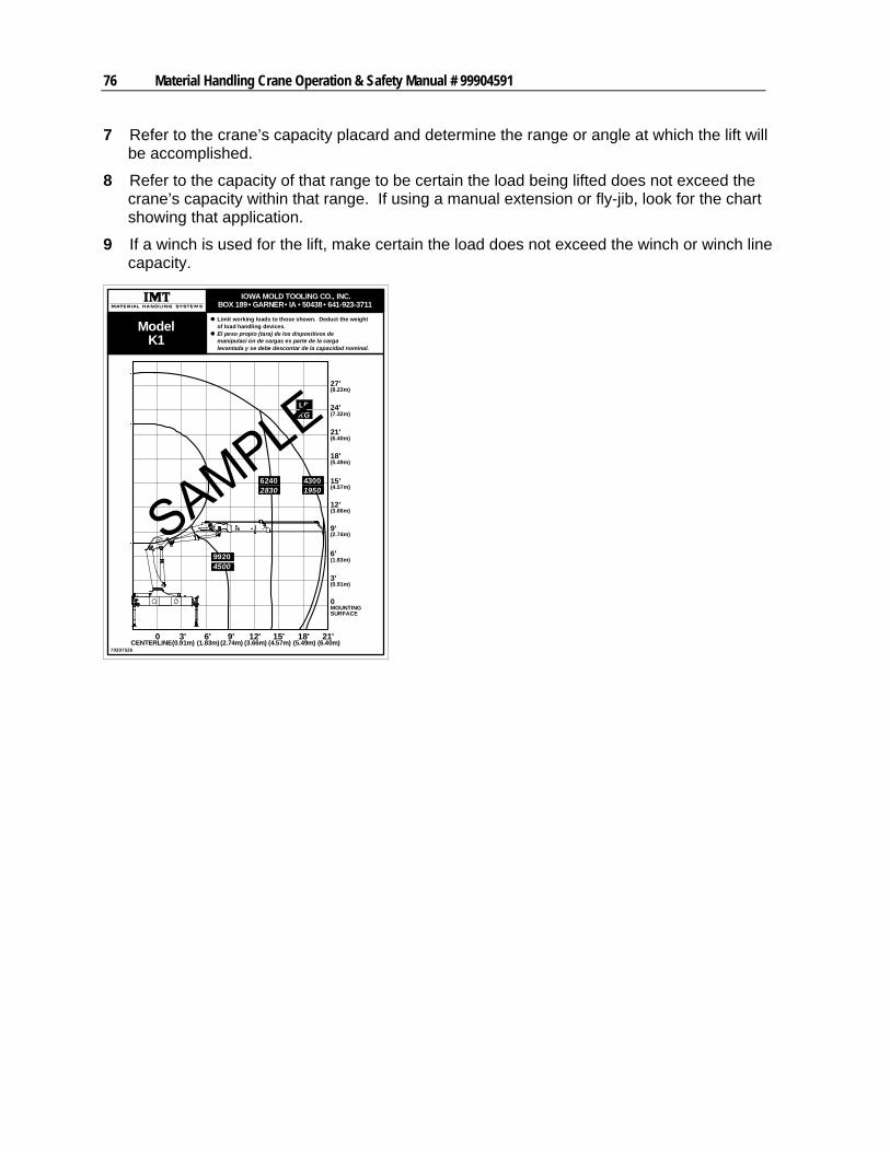
76 Material Handling Crane Operation & Safety Manual # 99904591
7 Refer to the crane’s capacity placard and determine the range or angle at which the lift will be accomplished.
8 Refer to the capacity of that range to be certain the load being lifted does not exceed the crane’s capacity within that range. If using a manual extension or fly-jib, look for the chart showing that application.
9 If a winch is used for the lift, make certain the load does not exceed the winch or winch line capacity.
70397526
IOWA MOLD TOOLING CO., INC.BOX 189• GARNER• IA • 50438• 641-923-3711
ModelK1
0CENTERLINE
3' 6' 9' 12' 15' 18' 21'(0.91m) (1.83m) (2.74m) (3.66m) (4.57m) (5.49m) (6.40m)
MOUNTINGSURFACE
3'
0
(0.91m)
6'(1.83m)
9'(2.74m)
12'(3.66m)
15'(4.57m)
18'(5.49m)
21'(6.40m)
24'(7.32m)
27'(8.23m)
62402830
43001950
99204500
KGLB
Limit working loads to those shown. Deduct the weightof load handling devices.El peso propio (tara) de los dispositivos demanipulaci ón de cargas es parte de la cargalevantada y se debe descontar de la capacidad nominal.
77
Crane Stability
Every IMT factory-installed crane includes a completed stability chart. Any installer other than IMT also has the responsibility to complete a stability chart. Cranes are tested for stability to 85% of “tipping” based on the balance point for a specific truck and crane combination. The Stability Test is per SAE J765a. Figures entered on the stability chart are for a specific truck and crane combination. If the crane or vehicle are modified or replaced with another, it is necessary to recalculate stability. By referring to the stability chart for your crane/chassis combination, it is possible to determine the loads permitted in the derated load range of your crane.The “tipping point” is defined as the balance point, which per SAE J765a is when the load on the crane is balanced with the load of the truck and stabilizers. Any additional load will cause the truck to tip. Cranes are tested for stability to 85% of the balance point.
SET-UP:
1 The testing area must be a flat, hard surface (ideally concrete, but asphalt or hard-packed gravel is acceptable). Only authorized testing personnel will be in or near the test area. SAE J765a specifies that the area must be within 1% of level.
2 Position and lower stabilizers until the weight of the crane has been removed from the truck springs. Use all stabilizers. Make sure the truck is level and all stabilizers are in contact with the ground.
3 Operate the crane under partial load to assure operator proficiency and proper machine function.
STABILITY TEST:
1 Extend the crane to full horizontal position, centered over the rear of the truck.
2 From the capacity placard, determine the rated load at the maximum horizontal reach. Place a weight equal to 118% of that rated load at the maximum horizontal reach (L).
Maximum horizontal reach (L)
ft
Test load value lb
WARNING
At 118% of rated capacity, you are in overload! Operate the crane very carefully. Keep the load within 3.9” (0.1 m) of the ground at all times, and operate controls slowly.
3 Slowly start rotating the load counterclockwise. Through each area on Figure 1 (30° increments), check for stability. If the crane carries the load through the entire area without becoming unstable, the crane is stable in that area, and 100% can be noted in the area in Figure 1.
78 Material Handling Crane Operation & Safety Manual # 99904591
NOTE
The tires can lift from the ground without the truck becoming unstable. The truck is unstable when it reaches the balance point.
4 If at any point through the rotation cycle the vehicle becomes unstable, stop the rotation. Determine the area, as shown in Figure 1, in which the crane is positioned.
5 Retract the extension boom until stability is regained. Measure the horizontal reach when the unit is stable, from the center of rotation to the boom tip. Note this reach in Figure 1, in the area which became unstable in step #4.
6 Continue rotating the boom after stability has been regained. Again, watch for instability as defined by the balance point. If a point of instability reoccurs, retract the extension boom until stability is regained. Again, measure the stable horizontal reach at this point, and note this distance in the appropriate area in Figure 1.
7 Repeat this cycle through a full 180° of arc. Fill in all of the reach boxes for Areas 1 through 5 in Figure 1. Repeat for Areas 6 through 10.
8 If the crane was stable in all areas, fill in 100% in all of the percentage boxes in Figure 1.
9 If the stable horizontal reach in any area was less than the maximum horizontal reach (L, noted in step 2), calculate the percent of full capacity allowed in the area as follows:
10 Enter the derated percent of full capacity, calculated in step 8, on Figure 1. In the derated zone, each individual capacity on the capacity placard must be multiplied by the derated percent of full capacity. The reduced capacities maintain 85% of tipping in the derated zone.
NOTES:
1 The figures obtained indicate the stability range of that particular truck and crane combination, only. If either the truck or crane is changed or modified, the stability calculations must be repeated.
2 Contact IMT if you need a modified stability chart for your vehicle.
3 Rotate the crane at least 5 times using the completed figures to ensure the rating is accurate.
4 Be sure all information is recorded on the appropriate figure, and in the service manual.
5 Record the total length of time to test the crane (total crane test and inspection time should approximate 4 hours - 1979 SAE J765a). ________________ hrs.
Where applicable, this test conforms to SAE J765a, ASME B30.5 and ASME B30.22.
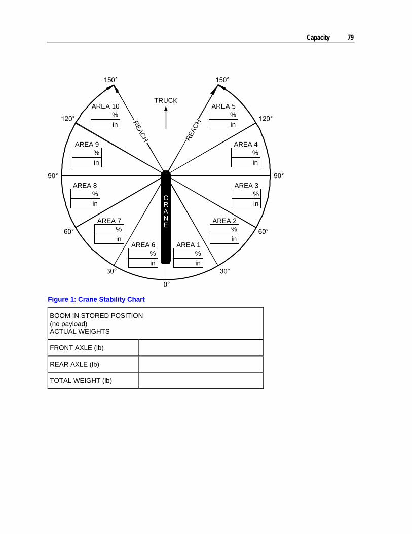
Capacity 79
RE
AC
HRE
AC
H
AREA 10%
in
AREA 9%
in
AREA 8%
in
AREA 7%
inAREA 6
%
in
AREA 1%
in
AREA 2%
in
AREA 3%
in
AREA 4%
in
AREA 5%
in
TRUCK
Figure 1: Crane Stability Chart
BOOM IN STORED POSITION (no payload) ACTUAL WEIGHTS
FRONT AXLE (lb)
REAR AXLE (lb)
TOTAL WEIGHT (lb)

81
In This Chapter
Crane Maintenance Precautions ................................................81 Daily Maintenance......................................................................82 Recommended Oil & Grease .....................................................83 Grease Points.............................................................................84 Greasing - Central Grease Point on Loader Base......................85 Greasing Push Rods at the Inner and Outer Boom Cylinders....86 Greasing Boom System Sliding Surfaces ..................................88 Bleeding Air from Cylinders........................................................88 Repair.........................................................................................88 Chemical Safety .........................................................................89
Crane Maintenance Precautions
Proper and regular maintenance of the crane is a very important safety factor. As in the operation of the crane, there are also precautions to take during crane maintenance. Before beginning any maintenance, familiarize yourself with the maintenance sections of any manuals for the equipment being repaired. Before starting work:
1 Place the crane in an area where other equipment is not operating and where there is no through traffic.
2 Make certain the carrier vehicle’s parking brake is set. Use wheel chocks to prevent vehicle movement.
3 Position the crane in its stowed position if possible or with the boom lowered to the ground so that any booms will be prevented from collapsing during maintenance.
4 Place all controls in the “OFF” position and disable any means of starting the carrier vehicle or powering the crane.
5 Disconnect the PTO.
6 Secure sheaves and/or load blocks so they will not swing or fall during maintenance.
7 Relieve the hydraulic oil pressure from all circuits before disconnecting any hydraulic fittings or components.
C H A P T E R 9
Maintenance
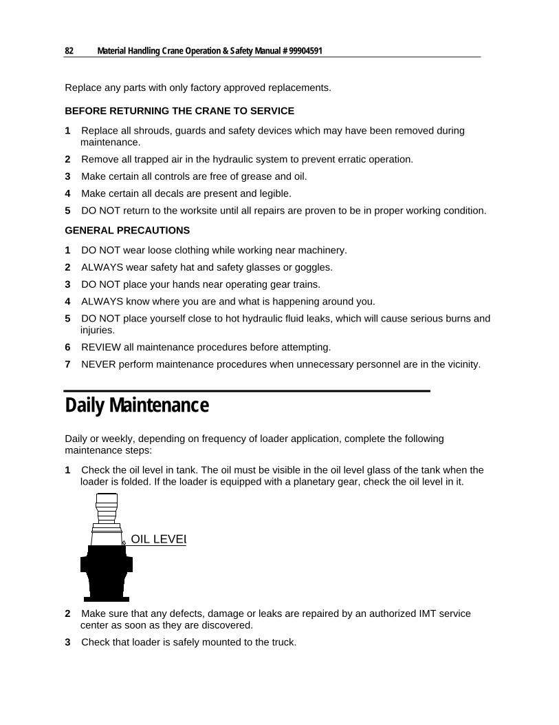
82 Material Handling Crane Operation & Safety Manual # 99904591
Replace any parts with only factory approved replacements. BEFORE RETURNING THE CRANE TO SERVICE
1 Replace all shrouds, guards and safety devices which may have been removed during maintenance.
2 Remove all trapped air in the hydraulic system to prevent erratic operation.
3 Make certain all controls are free of grease and oil.
4 Make certain all decals are present and legible.
5 DO NOT return to the worksite until all repairs are proven to be in proper working condition.
GENERAL PRECAUTIONS
1 DO NOT wear loose clothing while working near machinery.
2 ALWAYS wear safety hat and safety glasses or goggles.
3 DO NOT place your hands near operating gear trains.
4 ALWAYS know where you are and what is happening around you.
5 DO NOT place yourself close to hot hydraulic fluid leaks, which will cause serious burns and injuries.
6 REVIEW all maintenance procedures before attempting.
7 NEVER perform maintenance procedures when unnecessary personnel are in the vicinity.
Daily Maintenance
Daily or weekly, depending on frequency of loader application, complete the following maintenance steps:
1 Check the oil level in tank. The oil must be visible in the oil level glass of the tank when the loader is folded. If the loader is equipped with a planetary gear, check the oil level in it.
OIL LEVEL
2 Make sure that any defects, damage or leaks are repaired by an authorized IMT service center as soon as they are discovered.
3 Check that loader is safely mounted to the truck.
Chapter 9 Maintenance 83
4 Slide blocks and bushings reduce friction and are naturally subject to wear and tear. Replace slide blocks if too much free play is found in the boom system. Replace bushings before the metal components physically touch each other.
5 Check all hoses for defects and kinks.
6 Check that hooks, wire ropes, straps and the like are in good working order.
7 Check all lock pins and bolts for wear and tear.
CAUTION
If the loader is not folded after use, make sure that all cylinders are completely retracted at least once a day. This maintains the protective oil coating on the piston rods and prevents corrosion on the chromium surfaces. Additional lubrication may be required if the loader is not used regularly.
Recommended Oil & Grease
Crane lubrication requirements are important for both maintenance and safety. By reducing friction on pins and gears the crane will be more reliable and safer to operate. Different lubricants are required for different sections of your crane. Contact your lubricant supplier for specific product information. Grease your crane per the following lubrication specifications and intervals.
APPLICATION POINT LUBRICATION PRODUCT APPLICATION METHOD INTERVAL Pinion & Drive Gear Rotation Brake Turntable Bearing (rotate while greasing) Cylinder Pins Boom Hinge Pins Boom Rollers
Shell Alvania 2EP or Shell Retinax "A" or Mobilith AW2 or equivalent
Hand Grease Gun or Pneumatic Pressure Gun
Weekly
Planetary Gear Mobilube HD 80W90 or equivalent
Fill to Check Plug Monthly
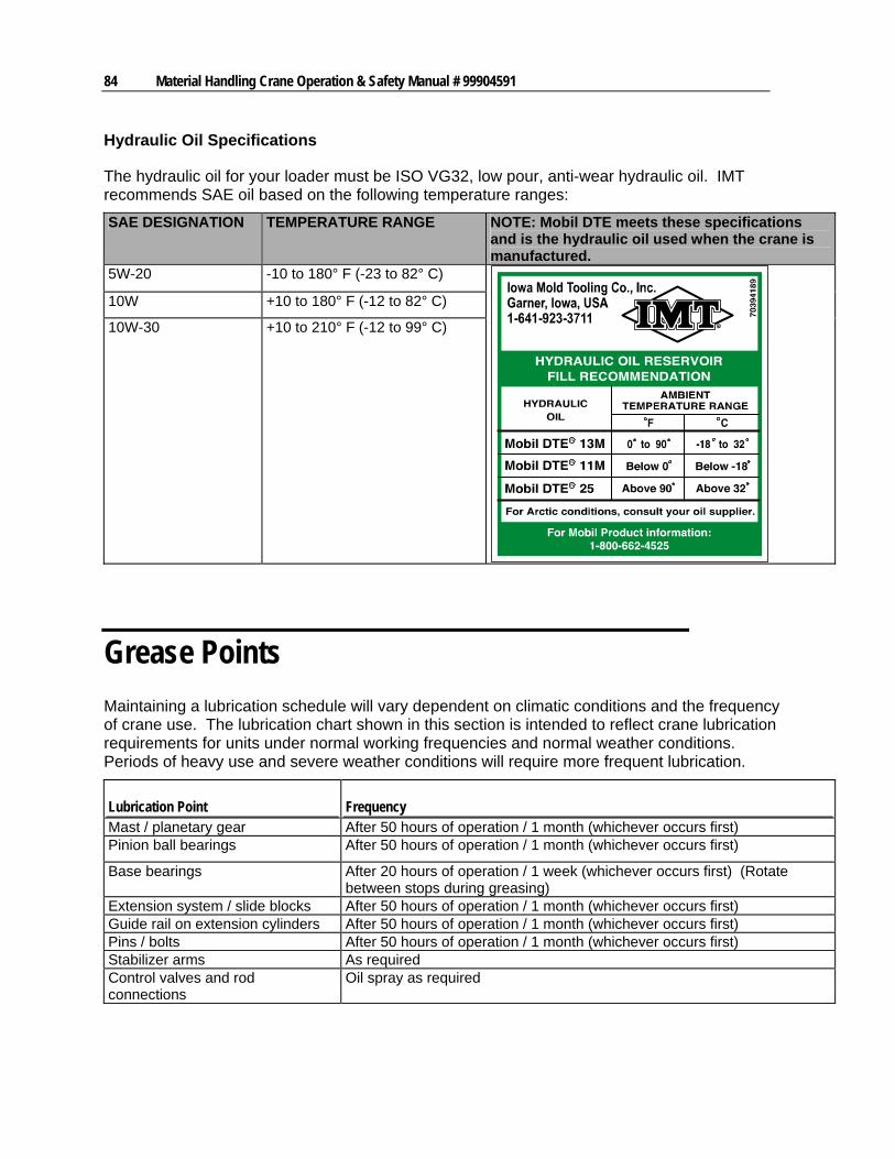
84 Material Handling Crane Operation & Safety Manual # 99904591
Hydraulic Oil Specifications
The hydraulic oil for your loader must be ISO VG32, low pour, anti-wear hydraulic oil. IMT recommends SAE oil based on the following temperature ranges:
SAE DESIGNATION TEMPERATURE RANGE NOTE: Mobil DTE meets these specifications and is the hydraulic oil used when the crane is manufactured.
5W-20 -10 to 180° F (-23 to 82° C)
10W +10 to 180° F (-12 to 82° C)
10W-30 +10 to 210° F (-12 to 99° C)
Grease Points
Maintaining a lubrication schedule will vary dependent on climatic conditions and the frequency of crane use. The lubrication chart shown in this section is intended to reflect crane lubrication requirements for units under normal working frequencies and normal weather conditions. Periods of heavy use and severe weather conditions will require more frequent lubrication.
Lubrication Point Frequency Mast / planetary gear After 50 hours of operation / 1 month (whichever occurs first) Pinion ball bearings After 50 hours of operation / 1 month (whichever occurs first)
Base bearings After 20 hours of operation / 1 week (whichever occurs first) (Rotate between stops during greasing)
Extension system / slide blocks After 50 hours of operation / 1 month (whichever occurs first) Guide rail on extension cylinders After 50 hours of operation / 1 month (whichever occurs first) Pins / bolts After 50 hours of operation / 1 month (whichever occurs first) Stabilizer arms As required Control valves and rod connections
Oil spray as required
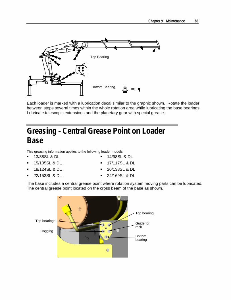
Chapter 9 Maintenance 85
Top Bearing
Bottom Bearing
Each loader is marked with a lubrication decal similar to the graphic shown. Rotate the loader between stops several times within the whole rotation area while lubricating the base bearings. Lubricate telescopic extensions and the planetary gear with special grease.
Greasing - Central Grease Point on Loader Base This greasing information applies to the following loader models:
13/88SL & DL 14/98SL & DL
15/105SL & DL 17/117SL & DL
18/124SL & DL 20/138SL & DL
22/153SL & DL 24/169SL & DL
The base includes a central grease point where rotation system moving parts can be lubricated. The central grease point located on the cross beam of the base as shown.
Top bearing
Guide forrack
Top bearing
Cogging
Bottombearing
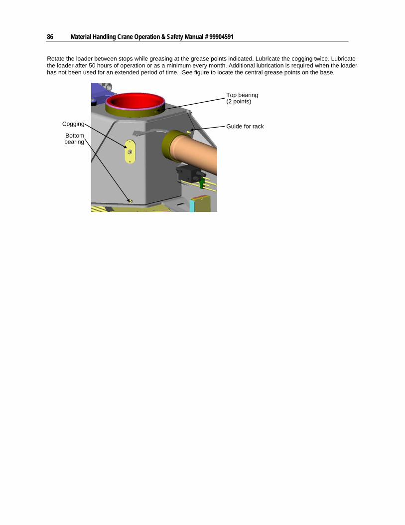
86 Material Handling Crane Operation & Safety Manual # 99904591
Rotate the loader between stops while greasing at the grease points indicated. Lubricate the cogging twice. Lubricate the loader after 50 hours of operation or as a minimum every month. Additional lubrication is required when the loader has not been used for an extended period of time. See figure to locate the central grease points on the base.
Cogging
Top bearing(2 points)
Guide for rack
Bottombearing
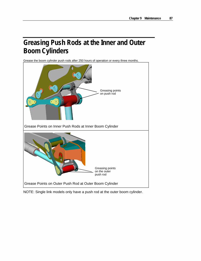
Chapter 9 Maintenance 87
Greasing Push Rods at the Inner and Outer Boom Cylinders Grease the boom cylinder push rods after 250 hours of operation or every three months.
Greasing pointson push rod
Grease Points on Inner Push Rods at Inner Boom Cylinder
Greasing pointson the outerpush rod
Grease Points on Outer Push Rod at Outer Boom Cylinder
NOTE: Single link models only have a push rod at the outer boom cylinder.
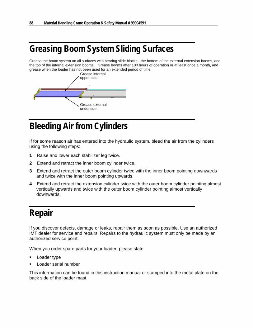
88 Material Handling Crane Operation & Safety Manual # 99904591
Greasing Boom System Sliding Surfaces Grease the boom system on all surfaces with bearing slide blocks - the bottom of the external extension booms, and the top of the internal extension booms. Grease booms after 100 hours of operation or at least once a month, and grease when the loader has not been used for an extended period of time.
Grease externalunderside.
Grease internalupper side.
Bleeding Air from Cylinders
If for some reason air has entered into the hydraulic system, bleed the air from the cylinders using the following steps:
1 Raise and lower each stabilizer leg twice.
2 Extend and retract the inner boom cylinder twice.
3 Extend and retract the outer boom cylinder twice with the inner boom pointing downwards and twice with the inner boom pointing upwards.
4 Extend and retract the extension cylinder twice with the outer boom cylinder pointing almost vertically upwards and twice with the outer boom cylinder pointing almost vertically downwards.
Repair
If you discover defects, damage or leaks, repair them as soon as possible. Use an authorized IMT dealer for service and repairs. Repairs to the hydraulic system must only be made by an authorized service point.
When you order spare parts for your loader, please state:
Loader type
Loader serial number
This information can be found in this instruction manual or stamped into the metal plate on the back side of the loader mast.

Chapter 9 Maintenance 89
Chemical Safety
Many chemicals are available for cleaning and lubricating your equipment. Prior to opening or using any chemical for cleaning, lubrication, or other procedure, READ THE LABEL.
Labels on chemical containers list important information on health, safety, and the product itself. This information can save you from serious injury or even DEATH. Some of this information may be the scientific or common name of the chemical, which is useful when describing poisoning conditions to a poison control center or doctor. The label also describes chemical properties such as flammability, combustibility, explosiveness, or corrosiveness. This information can save your life.
The label also provides advisories in how the product is to be used, such as, “Use only in a well-ventilated area”, “Keep away from heat”, or “Avoid contact with skin”. Always follow these and other warnings and instructions, and refer to the container for first aid instructions.
These warnings and advisories may also be posted in the area where chemicals are stored or used.
Chemicals and their containers have specific handling, storage, and disposal requirements. If these requirements aren't noted on the container, acquire the information from the chemical distributor or responsible governmental agency.


91
In This Chapter
Loader Safety Factors ................................................................91 Hydraulic System Design ...........................................................92 Load Moment Limitation .............................................................93 Heavy Duty Lifting - HDL............................................................94 Hoses and Hydraulic Pipes ........................................................94
Loader Safety Factors
Loader Structure Design & Test
This loader was designed to ensure bearing parts will last the lifetime of the product. During design and testing, the loader completed a long-term stress test corresponding as much as possible to actual operation. All loaders complete a quality control test during production to ensure they meet the design standards.
Safety in Control Circuits
Built-in electrohydraulic control circuits safety features include:
1 An adjustable main-relief valve in the inlet section of the valve block, factory pre-set to the maximum pressure so the loader’s lifting capacity is limited to the maximum permissible load. The pressure setting must not exceed the maximum permissible load and should always be sealed.
2 Port-relief valves in the control valve sections of the individual circuits which limit the hydraulic pressure to the individual cylinders, and minimize impact on the loader’s structure which might occur from sudden movements.
3 The boom, jib, and extension cylinders with load holding valves with the following main functions:
1. If the loader is overloaded and the pressure in the cylinders is too high, the load holding valve will open in order to relieve internal cylinder pressure.
2. In case of hose rupture, the load holding valve blocks the oil so that it cannot flow out of the cylinder, so the boom is maintained in position and the load is prevented from falling.
3. The load holding valves ensure that during mounting, the load is maintained in position for a length of time, even if the control valve is worn.
C H A P T E R 1 0
Crane Design
92 Material Handling Crane Operation & Safety Manual # 99904591
4. The load holding valves maintain the boom system in position if the operator tries to lower the boom system while the loader stands still and the hydraulic pump is stopped.
4 A piloted check-valve is fitted to each stabilizer leg to maintain the stabilizer cylinder in position in case of hose rupture. This device prevents the vehicle from overturning.
5 The hydraulic system forms part of a load moment limitation system (LMB) which ensures that the permissible load moment is never exceeded, irrespective of the operator’s actions. For further information, please see the individual loader instruction manual.
6 An emergency stop button is placed near each control station.
7 The operator is warned with a red light when the stress on the loader has reached 90% of the maximum permissible load.
8 The fully extended position of the stabilizer beams is clearly marked.
9 All controls are ensured against unintentional operation of the control levers by means of safety guards etc.
10 If a load is moved into an area (for instance over the driver’s cab) where the vehicle becomes unstable, the slewing movement is interrupted either mechanically or by means of an extended load moment limitation system. An extended load moment limitation system ensures that the loader can only be loaded with a limited load moment in this unstable area, so that the vehicle’s stability is maintained. When working in this area with a reduced load moment, the operator is warned via a yellow light.
11 If the loader is equipped with stand-up controls where the operator operates the loader standing on the base, a safety system automatically interrupts the slewing movement so that the boom system cannot be moved over the operator.
12 Many movable parts are shielded to protect the operator from injury.
13 If the loader is operated from a top seat (mounted on the column), the slewing system is equipped with a double load holding valve as security in case of hose rupture.
Hydraulic System Design
The loader valve block is a "stack" type, as it is made up of a number of separate control valves. This ensures great flexibility and low maintenance costs. A main relief valve is fitted in the inlet section of the valve block to ensure that the oil pressure in the pump line does not exceed the permissible limit. This valve is adjustable and must always remain sealed. Port relief valves are mounted at the ports of the individual control valves in order to limit the pressure in the individual circuits. Normally the port relief valves are pre-set and cannot be adjusted.
The inner boom, outer boom and extension cylinders are mounted with load holding valves which:
1 Protect cylinders against excessive pressure
2 Reduce the lowering speed of the boom
3 Maintain the boom in position during operations where a fixed boom position is required.
Chapter 10 Crane Design 93
4 Lock the boom and maintain the load in position in case of hose or pipe rupture.
The stabilizer cylinders are equipped with a piloted check valve, which locks the cylinder in case of damage to the hydraulic system.
CAUTION
The main relief valve, the load holding valves, the dump valve and the external relief valve are sealed. If these seals are broken or removed, the IMT warranty will automatically be void. Check seals regularly and replace if damaged.
Any modification or alteration to the hydraulic system must be in accordance to specific agreement with IMT. Hydraulic system maintenance should always take place at an authorized IMT service point.
Load Moment Limitation
The loader is equipped with a load moment limitation system (LMB) which prevents the maximum permissible load moment from being exceeded, in spite of operator error.
However, the LMB-system does not necessarily ensure sufficient vehicle stability. Before working with the loader, the operator must always make sure that the vehicle is stable in the entire rotation area of the loader.
If the loader is equipped with an EVS-system (Electronic Vehicle Stability), the stability of the vehicle is ensured in the entire working area, because the system is constantly checking the vehicle, and immediately stopping the load moment increasing movement in case of instability, irrespective of the operator’s doings. The LMB-system is described in the Instruction Manual - RCL Safety System. Be familiar with this manual.
94 Material Handling Crane Operation & Safety Manual # 99904591
Heavy Duty Lifting - HDL
If the loader is equipped with a Heavy Duty Lifting (HDL) system, an increased lifting capacity is available at reduced speed.
When the loader reaches its normal lifting capacity limit, the HDL-system will automatically activate, irrespective of the operator’s doings, and the oil flow to the control valve will be reduced to approximately 20% of the normal oil flow. At the same time the loader lifting capacity is increased by approximately 10% in the entire working area of the loader.
When the HDL-system is activated, the operator will be able to continue extending the load without interruption at reduced speed.
If the load moment is reduced to the permitted load limits again, the HDL-system will increase the oil flow to normal and the working speed will increase again.
The HDL-system will only disconnect automatically when all control levers have been released into neutral position at the same time as the load moment has been reduced to the permitted load limit.
See the section titled "Heavy Duty Lifting, HDL" in the RCL Safety System Instruction Manual.
Hoses and Hydraulic Pipes
The hoses comply with the DIN 20 022 2SN standards.
The pipes are manufactured in St.35.4C-NBK.
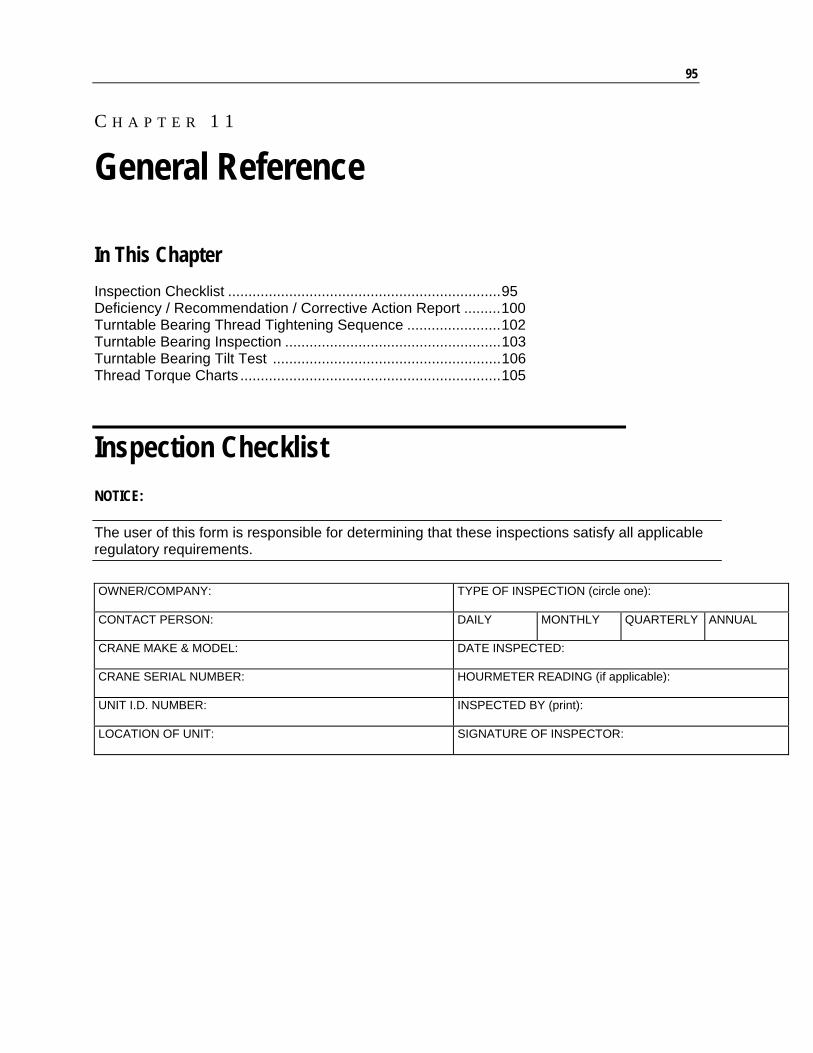
95
In This Chapter
Inspection Checklist ...................................................................95 Deficiency / Recommendation / Corrective Action Report .........100 Turntable Bearing Thread Tightening Sequence .......................102 Turntable Bearing Inspection .....................................................103 Turntable Bearing Tilt Test ........................................................106 Thread Torque Charts ................................................................105
Inspection Checklist
NOTICE:
The user of this form is responsible for determining that these inspections satisfy all applicable regulatory requirements.
OWNER/COMPANY:
TYPE OF INSPECTION (circle one):
CONTACT PERSON: DAILY MONTHLY QUARTERLY ANNUAL
CRANE MAKE & MODEL: DATE INSPECTED:
CRANE SERIAL NUMBER: HOURMETER READING (if applicable):
UNIT I.D. NUMBER:
INSPECTED BY (print):
LOCATION OF UNIT: SIGNATURE OF INSPECTOR:
C H A P T E R 1 1
General Reference
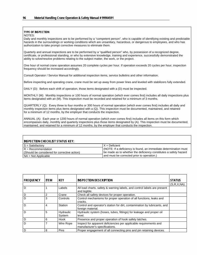
96 Material Handling Crane Operation & Safety Manual # 99904591
TYPE OF INSPECTION NOTES: Daily and monthly inspections are to be performed by a “competent person”, who is capable of identifying existing and predictable hazards in the surroundings or working conditions which are unsanitary, hazardous, or dangerous to employees, and who has authorization to take prompt corrective measures to eliminate them. Quarterly and annual inspections are to be performed by a “qualified person” who, by possession of a recognized degree, certificate, or professional standing, or who by extensive knowledge, training and experience, successfully demonstrated the ability to solve/resolve problems relating to the subject matter, the work, or the project. One hour of normal crane operation assumes 20 complete cycles per hour. If operation exceeds 20 cycles per hour, inspection frequency should be increased accordingly. Consult Operator / Service Manual for additional inspection items, service bulletins and other information. Before inspecting and operating crane, crane must be set up away from power lines and leveled with stabilizers fully extended. DAILY (D): Before each shift of operation, those items designated with a (D) must be inspected. MONTHLY (M): Monthly inspections or 100 hours of normal operation (which ever comes first) includes all daily inspections plus items designated with an (M). This inspection must be recorded and retained for a minimum of 3 months. QUARTERLY (Q): Every three to four months or 300 hours of normal operation (which ever comes first) includes all daily and monthly inspection items plus items designated with a (Q). This inspection must be documented, maintained, and retained for a minimum of 12 months, by the employer that conducts the inspection. ANNUAL (A): Each year or 1200 hours of normal operation (which ever comes first) includes all items on this form which encompasses daily, monthly and quarterly inspections plus those items designated by (A). This inspection must be documented, maintained, and retained for a minimum of 12 months, by the employer that conducts the inspection.
INSPECTION CHECKLIST STATUS KEY: S = Satisfactory R = Recommendation (Should be considered for corrective action) NA = Not Applicable
X = Deficient (NOTE: If a deficiency is found, an immediate determination must be made as to whether the deficiency constitutes a safety hazard and must be corrected prior to operation.)
FREQUENCY ITEM KEY INSPECTION DESCRIPTION STATUS (S,R,X,NA)
D 1 Labels All load charts, safety & warning labels, and control labels are present and legible.
D 2 Crane Check all safety devices for proper operation. D 3 Controls Control mechanisms for proper operation of all functions, leaks and
cracks.
D 4 Station Control and operator's station for dirt, contamination by lubricants, and foreign material.
D 5 Hydraulic System
Hydraulic system (hoses, tubes, fittings) for leakage and proper oil level.
D 6 Hook Presence and proper operation of hook safety latches.
D 7 Wire Rope Inspect for apparent deficiencies per applicable requirements and manufacturer’s specifications.
D 8 Pins Proper engagement of all connecting pins and pin retaining devices.
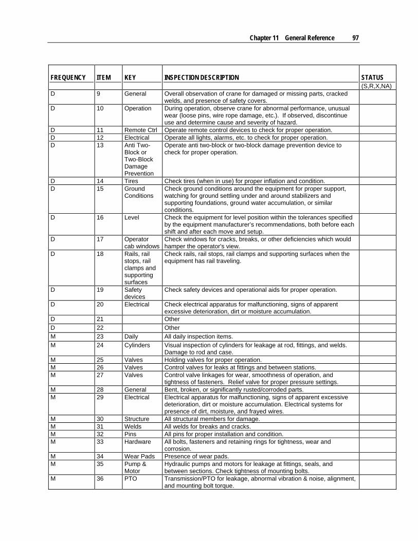
Chapter 11 General Reference 97
FREQUENCY ITEM KEY INSPECTION DESCRIPTION STATUS (S,R,X,NA)
D 9 General Overall observation of crane for damaged or missing parts, cracked welds, and presence of safety covers.
D 10 Operation During operation, observe crane for abnormal performance, unusual wear (loose pins, wire rope damage, etc.). If observed, discontinue use and determine cause and severity of hazard.
D 11 Remote Ctrl Operate remote control devices to check for proper operation. D 12 Electrical Operate all lights, alarms, etc. to check for proper operation. D 13 Anti Two-
Block or Two-Block Damage Prevention
Operate anti two-block or two-block damage prevention device to check for proper operation.
D 14 Tires Check tires (when in use) for proper inflation and condition. D 15 Ground
Conditions Check ground conditions around the equipment for proper support, watching for ground settling under and around stabilizers and supporting foundations, ground water accumulation, or similar conditions.
D 16 Level Check the equipment for level position within the tolerances specified by the equipment manufacturer’s recommendations, both before each shift and after each move and setup.
D 17 Operator cab windows
Check windows for cracks, breaks, or other deficiencies which would hamper the operator's view.
D 18 Rails, rail stops, rail clamps and supporting surfaces
Check rails, rail stops, rail clamps and supporting surfaces when the equipment has rail traveling.
D 19 Safety devices
Check safety devices and operational aids for proper operation.
D 20 Electrical Check electrical apparatus for malfunctioning, signs of apparent excessive deterioration, dirt or moisture accumulation.
D 21 Other
D 22 Other
M 23 Daily All daily inspection items.
M 24 Cylinders Visual inspection of cylinders for leakage at rod, fittings, and welds. Damage to rod and case.
M 25 Valves Holding valves for proper operation. M 26 Valves Control valves for leaks at fittings and between stations. M 27 Valves Control valve linkages for wear, smoothness of operation, and
tightness of fasteners. Relief valve for proper pressure settings.
M 28 General Bent, broken, or significantly rusted/corroded parts. M 29 Electrical Electrical apparatus for malfunctioning, signs of apparent excessive
deterioration, dirt or moisture accumulation. Electrical systems for presence of dirt, moisture, and frayed wires.
M 30 Structure All structural members for damage. M 31 Welds All welds for breaks and cracks. M 32 Pins All pins for proper installation and condition. M 33 Hardware All bolts, fasteners and retaining rings for tightness, wear and
corrosion.
M 34 Wear Pads Presence of wear pads. M 35 Pump &
Motor Hydraulic pumps and motors for leakage at fittings, seals, and between sections. Check tightness of mounting bolts.
M 36 PTO Transmission/PTO for leakage, abnormal vibration & noise, alignment, and mounting bolt torque.
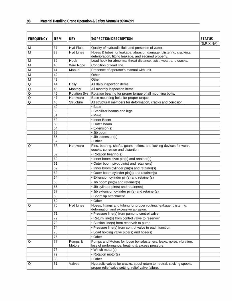
98 Material Handling Crane Operation & Safety Manual # 99904591
FREQUENCY ITEM KEY INSPECTION DESCRIPTION STATUS (S,R,X,NA)
M 37 Hyd Fluid Quality of hydraulic fluid and presence of water. M 38 Hyd Lines Hoses & tubes for leakage, abrasion damage, blistering, cracking,
deterioration, fitting leakage, and secured properly.
M 39 Hook Load hook for abnormal throat distance, twist, wear, and cracks. M 40 Wire Rope Condition of load line. M 41 Manual Presence of operator's manual with unit.
M 42 Other M 43 Other Q 44 Daily All daily inspection items.
Q 45 Monthly All monthly inspection items. Q 46 Rotation Sys Rotation bearing for proper torque of all mounting bolts. Q 47 Hardware Base mounting bolts for proper torque. Q 48 Structure All structural members for deformation, cracks and corrosion. 49 • Base 50 • Stabilizer beams and legs 51 • Mast 52 • Inner Boom 53 • Outer Boom 54 • Extension(s) 55 • Jib boom 56 • Jib extension(s) 57 • Other Q 58 Hardware Pins, bearing, shafts, gears, rollers, and locking devices for wear,
cracks, corrosion and distortion.
59 • Rotation bearing(s) 60 • Inner boom pivot pin(s) and retainer(s) 61 • Outer boom pivot pin(s) and retainer(s) 62 • Inner boom cylinder pin(s) and retainer(s) 63 • Outer boom cylinder pin(s) and retainer(s) 64 • Extension cylinder pin(s) and retainer(s) 65 • Jib boom pin(s) and retainer(s) 66 • Jib cylinder pin(s) and retainer(s) 67 • Jib extension cylinder pin(s) and retainer(s) 68 • Boom tip attachment 69 • Other Q 70 Hyd Lines Hoses, fittings and tubing for proper routing, leakage, blistering,
deformation and excessive abrasion.
71 • Pressure line(s) from pump to control valve 72 • Return line(s) from control valve to reservoir 73 • Suction line(s) from reservoir to pump 74 • Pressure line(s) from control valve to each function 75 • Load holding valve pipe(s) and hose(s) 76 • Other Q 77 Pumps &
Motors Pumps and Motors for loose bolts/fasteners, leaks, noise, vibration, loss of performance, heating & excess pressure.
78 • Winch motor(s) 79 • Rotation motor(s) 80 • Other Q 81 Valves Hydraulic valves for cracks, spool return to neutral, sticking spools,
proper relief valve setting, relief valve failure.
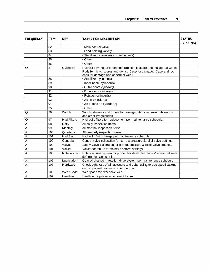
Chapter 11 General Reference 99
FREQUENCY ITEM KEY INSPECTION DESCRIPTION STATUS (S,R,X,NA)
82 • Main control valve 83 • Load holding valve(s) 84 • Stabilizer or auxiliary control valve(s) 85 • Other 86 • Other Q 87 Cylinders Hydraulic cylinders for drifting, rod seal leakage and leakage at welds.
Rods for nicks, scores and dents. Case for damage. Case and rod ends for damage and abnormal wear.
88 • Stabilizer cylinder(s) 89 • Inner boom cylinder(s) 90 • Outer boom cylinder(s) 91 • Extension cylinder(s) 92 • Rotation cylinder(s) 93 • Jib lift cylinder(s) 94 • Jib extension cylinder(s) 95 • Other Q 96 Winch Winch, sheaves and drums for damage, abnormal wear, abrasions
and other irregularities.
Q 97 Hyd Filters Hydraulic filters for replacement per maintenance schedule. A 98 Daily All daily inspection items. A 99 Monthly All monthly inspection items. A 100 Quarterly All quarterly inspection items. A 101 Hyd Sys Hydraulic fluid change per maintenance schedule. A 102 Controls Control valve calibration for correct pressure & relief valve settings. A 103 Valves Safety valve calibration for correct pressure & relief valve settings. A 104 Valves Valves for failure to maintain correct settings. A 105 Rotation Sys Rotation drive system for proper backlash clearance & abnormal wear,
deformation and cracks.
A 106 Lubrication Gear oil change in rotation drive system per maintenance schedule. A 107 Hardware Check tightness of all fasteners and bolts, using torque specifications
on component drawings or torque chart.
A 108 Wear Pads Wear pads for excessive wear. A 109 Loadline Loadline for proper attachment to drum.
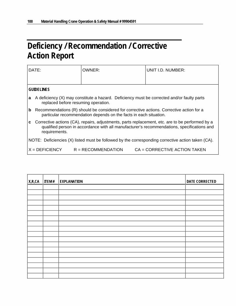
100 Material Handling Crane Operation & Safety Manual # 99904591
Deficiency / Recommendation / Corrective Action Report
DATE: OWNER: UNIT I.D. NUMBER:
GUIDELINES
a A deficiency (X) may constitute a hazard. Deficiency must be corrected and/or faulty parts replaced before resuming operation.
b Recommendations (R) should be considered for corrective actions. Corrective action for a particular recommendation depends on the facts in each situation.
c Corrective actions (CA), repairs, adjustments, parts replacement, etc. are to be performed by a qualified person in accordance with all manufacturer’s recommendations, specifications and requirements.
NOTE: Deficiencies (X) listed must be followed by the corresponding corrective action taken (CA).
X = DEFICIENCY R = RECOMMENDATION CA = CORRECTIVE ACTION TAKEN
X,R,CA ITEM # EXPLANATION DATE CORRECTED

Chapter 11 General Reference 101
X,R,CA ITEM # EXPLANATION DATE CORRECTED
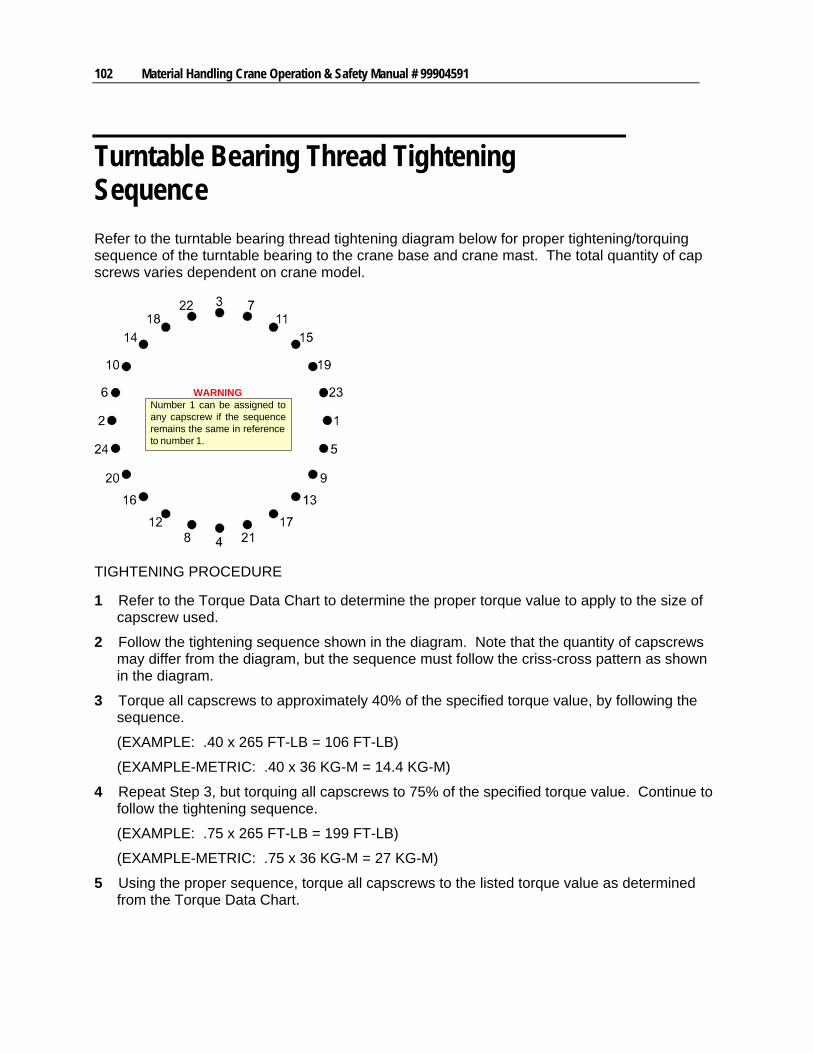
102 Material Handling Crane Operation & Safety Manual # 99904591
Turntable Bearing Thread Tightening Sequence
Refer to the turntable bearing thread tightening diagram below for proper tightening/torquing sequence of the turntable bearing to the crane base and crane mast. The total quantity of cap screws varies dependent on crane model.
Number 1 can be assigned toany capscrew if the sequenceremains the same in referenceto number 1.
WARNING
TIGHTENING PROCEDURE
1 Refer to the Torque Data Chart to determine the proper torque value to apply to the size of capscrew used.
2 Follow the tightening sequence shown in the diagram. Note that the quantity of capscrews may differ from the diagram, but the sequence must follow the criss-cross pattern as shown in the diagram.
3 Torque all capscrews to approximately 40% of the specified torque value, by following the sequence.
(EXAMPLE: .40 x 265 FT-LB = 106 FT-LB)
(EXAMPLE-METRIC: .40 x 36 KG-M = 14.4 KG-M)
4 Repeat Step 3, but torquing all capscrews to 75% of the specified torque value. Continue to follow the tightening sequence.
(EXAMPLE: .75 x 265 FT-LB = 199 FT-LB)
(EXAMPLE-METRIC: .75 x 36 KG-M = 27 KG-M)
5 Using the proper sequence, torque all capscrews to the listed torque value as determined from the Torque Data Chart.
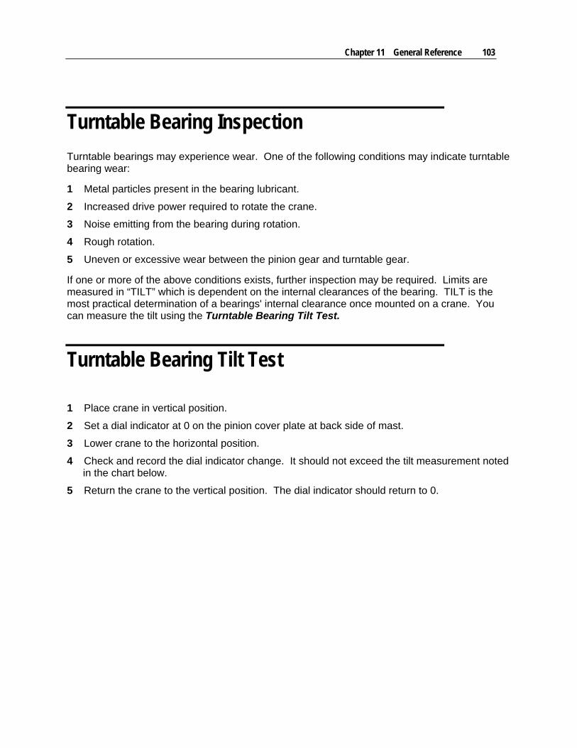
Chapter 11 General Reference 103
Turntable Bearing Inspection
Turntable bearings may experience wear. One of the following conditions may indicate turntable bearing wear:
1 Metal particles present in the bearing lubricant.
2 Increased drive power required to rotate the crane.
3 Noise emitting from the bearing during rotation.
4 Rough rotation.
5 Uneven or excessive wear between the pinion gear and turntable gear.
If one or more of the above conditions exists, further inspection may be required. Limits are measured in “TILT” which is dependent on the internal clearances of the bearing. TILT is the most practical determination of a bearings' internal clearance once mounted on a crane. You can measure the tilt using the Turntable Bearing Tilt Test.
Turntable Bearing Tilt Test
1 Place crane in vertical position.
2 Set a dial indicator at 0 on the pinion cover plate at back side of mast.
3 Lower crane to the horizontal position.
4 Check and record the dial indicator change. It should not exceed the tilt measurement noted in the chart below.
5 Return the crane to the vertical position. The dial indicator should return to 0.
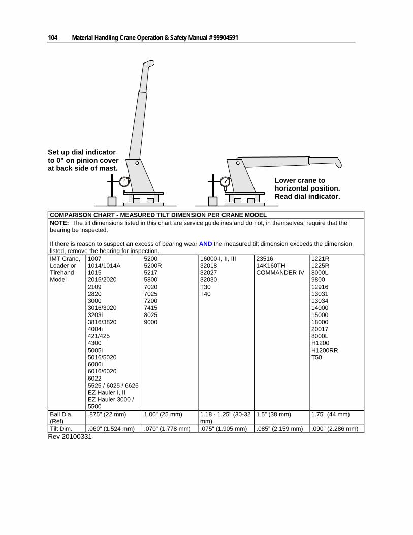
104 Material Handling Crane Operation & Safety Manual # 99904591
Set up dial indicatorto 0" on pinion coverat back side of mast.
Lower crane tohorizontal position.Read dial indicator.
COMPARISON CHART - MEASURED TILT DIMENSION PER CRANE MODEL NOTE: The tilt dimensions listed in this chart are service guidelines and do not, in themselves, require that the bearing be inspected. If there is reason to suspect an excess of bearing wear AND the measured tilt dimension exceeds the dimension listed, remove the bearing for inspection. IMT Crane, Loader or Tirehand Model
1007 1014/1014A 1015 2015/2020 2109 2820 3000 3016/3020 3203i 3816/3820 4004i 421/425 4300 5005i 5016/5020 6006i 6016/6020 6022 5525 / 6025 / 6625 EZ Hauler I, II EZ Hauler 3000 / 5500
5200 5200R 5217 5800 7020 7025 7200 7415 8025 9000
16000-I, II, III 32018 32027 32030 T30 T40
23516 14K160TH COMMANDER IV
1221R 1225R 8000L 9800 12916 13031 13034 14000 15000 18000 20017 8000L H1200 H1200RR T50
Ball Dia. (Ref)
.875" (22 mm) 1.00" (25 mm) 1.18 - 1.25" (30-32 mm)
1.5” (38 mm) 1.75" (44 mm)
Tilt Dim. .060" (1.524 mm) .070" (1.778 mm) .075" (1.905 mm) .085” (2.159 mm) .090" (2.286 mm) Rev 20100331
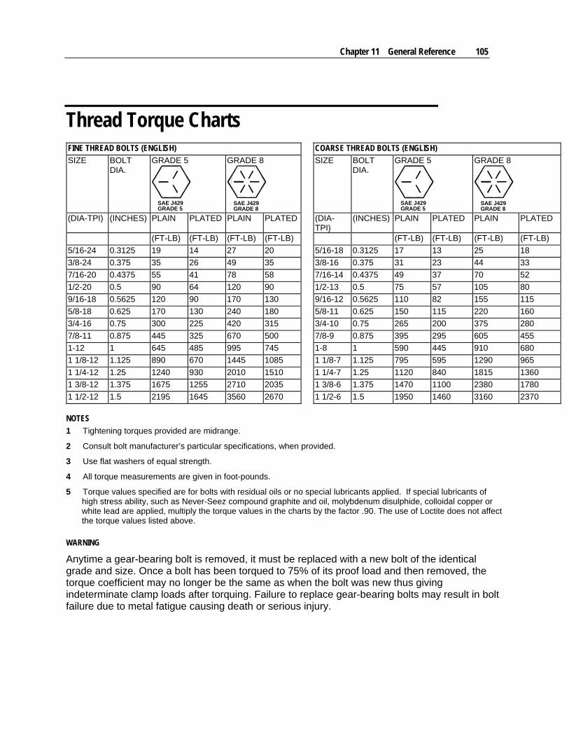
Chapter 11 General Reference 105
Thread Torque Charts FINE THREAD BOLTS (ENGLISH) COARSE THREAD BOLTS (ENGLISH)
SIZE BOLT DIA.
GRADE 5
SAE J429GRADE 5
GRADE 8
SAE J429GRADE 8
SIZE BOLT DIA.
GRADE 5
SAE J429GRADE 5
GRADE 8
SAE J429GRADE 8
(DIA-TPI) (INCHES) PLAIN PLATED PLAIN PLATED (DIA-TPI)
(INCHES) PLAIN PLATED PLAIN PLATED
(FT-LB) (FT-LB) (FT-LB) (FT-LB) (FT-LB) (FT-LB) (FT-LB) (FT-LB)
5/16-24 0.3125 19 14 27 20 5/16-18 0.3125 17 13 25 18
3/8-24 0.375 35 26 49 35 3/8-16 0.375 31 23 44 33
7/16-20 0.4375 55 41 78 58 7/16-14 0.4375 49 37 70 52
1/2-20 0.5 90 64 120 90 1/2-13 0.5 75 57 105 80
9/16-18 0.5625 120 90 170 130 9/16-12 0.5625 110 82 155 115
5/8-18 0.625 170 130 240 180 5/8-11 0.625 150 115 220 160
3/4-16 0.75 300 225 420 315 3/4-10 0.75 265 200 375 280
7/8-11 0.875 445 325 670 500 7/8-9 0.875 395 295 605 455
1-12 1 645 485 995 745 1-8 1 590 445 910 680
1 1/8-12 1.125 890 670 1445 1085 1 1/8-7 1.125 795 595 1290 965
1 1/4-12 1.25 1240 930 2010 1510 1 1/4-7 1.25 1120 840 1815 1360
1 3/8-12 1.375 1675 1255 2710 2035 1 3/8-6 1.375 1470 1100 2380 1780
1 1/2-12 1.5 2195 1645 3560 2670 1 1/2-6 1.5 1950 1460 3160 2370
NOTES
1 Tightening torques provided are midrange.
2 Consult bolt manufacturer’s particular specifications, when provided.
3 Use flat washers of equal strength.
4 All torque measurements are given in foot-pounds.
5 Torque values specified are for bolts with residual oils or no special lubricants applied. If special lubricants of high stress ability, such as Never-Seez compound graphite and oil, molybdenum disulphide, colloidal copper or white lead are applied, multiply the torque values in the charts by the factor .90. The use of Loctite does not affect the torque values listed above.
WARNING
Anytime a gear-bearing bolt is removed, it must be replaced with a new bolt of the identical grade and size. Once a bolt has been torqued to 75% of its proof load and then removed, the torque coefficient may no longer be the same as when the bolt was new thus giving indeterminate clamp loads after torquing. Failure to replace gear-bearing bolts may result in bolt failure due to metal fatigue causing death or serious injury.
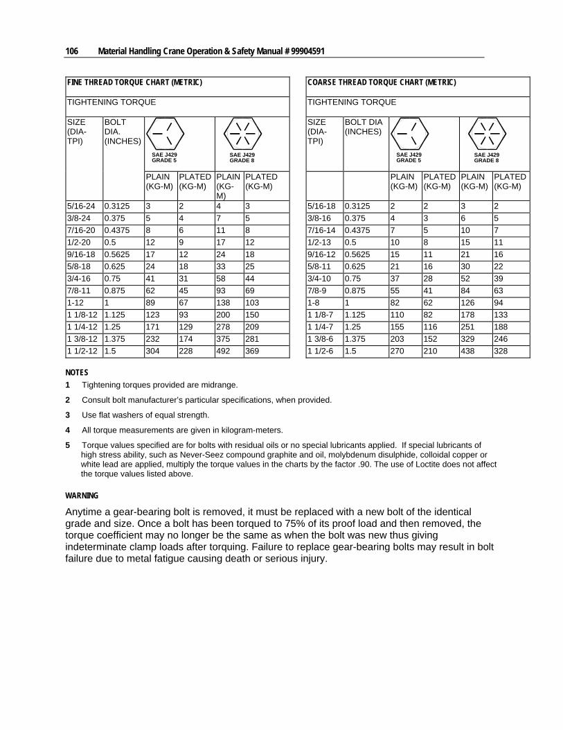
106 Material Handling Crane Operation & Safety Manual # 99904591
FINE THREAD TORQUE CHART (METRIC)
COARSE THREAD TORQUE CHART (METRIC)
TIGHTENING TORQUE
TIGHTENING TORQUE
SAE J429GRADE 5
SAE J429GRADE 8
SIZE (DIA-TPI)
BOLT DIA (INCHES)
SAE J429GRADE 5
SAE J429GRADE 8
SIZE (DIA-TPI)
BOLT DIA. (INCHES)
PLAIN (KG-M)
PLATED (KG-M)
PLAIN (KG-M)
PLATED (KG-M)
PLAIN (KG-M)
PLATED (KG-M)
PLAIN (KG-M)
PLATED (KG-M)
5/16-24 0.3125 3 2 4 3 5/16-18 0.3125 2 2 3 2
3/8-24 0.375 5 4 7 5 3/8-16 0.375 4 3 6 5
7/16-20 0.4375 8 6 11 8 7/16-14 0.4375 7 5 10 7
1/2-20 0.5 12 9 17 12 1/2-13 0.5 10 8 15 11
9/16-18 0.5625 17 12 24 18 9/16-12 0.5625 15 11 21 16
5/8-18 0.625 24 18 33 25 5/8-11 0.625 21 16 30 22
3/4-16 0.75 41 31 58 44 3/4-10 0.75 37 28 52 39
7/8-11 0.875 62 45 93 69 7/8-9 0.875 55 41 84 63
1-12 1 89 67 138 103 1-8 1 82 62 126 94
1 1/8-12 1.125 123 93 200 150 1 1/8-7 1.125 110 82 178 133
1 1/4-12 1.25 171 129 278 209 1 1/4-7 1.25 155 116 251 188
1 3/8-12 1.375 232 174 375 281 1 3/8-6 1.375 203 152 329 246
1 1/2-12 1.5 304 228 492 369 1 1/2-6 1.5 270 210 438 328
NOTES
1 Tightening torques provided are midrange.
2 Consult bolt manufacturer’s particular specifications, when provided.
3 Use flat washers of equal strength.
4 All torque measurements are given in kilogram-meters.
5 Torque values specified are for bolts with residual oils or no special lubricants applied. If special lubricants of high stress ability, such as Never-Seez compound graphite and oil, molybdenum disulphide, colloidal copper or white lead are applied, multiply the torque values in the charts by the factor .90. The use of Loctite does not affect the torque values listed above.
WARNING
Anytime a gear-bearing bolt is removed, it must be replaced with a new bolt of the identical grade and size. Once a bolt has been torqued to 75% of its proof load and then removed, the torque coefficient may no longer be the same as when the bolt was new thus giving indeterminate clamp loads after torquing. Failure to replace gear-bearing bolts may result in bolt failure due to metal fatigue causing death or serious injury.