Embed Size (px)
Citation preview

Mate
rial
handling
F1
Material Handling
Raw materials. Manufacturing supplies. Finished products. Unless it’s all moving, production isn’t really happening. IAC complements workstations with the material handling equipment needed to allow product to move and true production to take place.
Mobile Accessory Stations, Stationary Accessory Stations, and D4 Rolling Carts continue Dimension 4 construction and style. MTS rolling carts are heavy gauge mobile platforms for shelving, parts cup holders
and other accessories. Mobile cabinets are lockable for storing valuable tools, instruments or personal belongings – roll them to wherever the action is.
Gravity Feed Racks* (not shown) and Conveyor Systems are stationary, but they keep essential parts, products and the like moving and within reach of production workers.
*Gravity Feed Racks are special order only.
Mate
rialhandling
F2
Material Handling
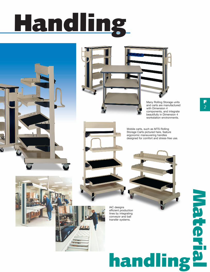
Many Rolling Storage units and carts are manufactured with Dimension 4 components, and integrate beautifully in Dimension 4 workstation environments.
Mobile carts, such as MTS Rolling Storage Carts pictured here, feature ergonomic maneuvering handles designed for comfort and stress-free use.
IAC designs efficient production lines by integrating conveyor and ball transfer systems.

Material HandlingM
ate
rial
handling
F3
TrimColor
BaseColor
LaminateColor
Casters
BlackT-mold
htdiW htgneLthgieHtraCdradnatS dradnatS
rewoLflehS
thgieHtraCDSE DSErewoLflehS˝03 ˝23 ˝43 ˝63 ˝03 ˝23 ˝43 ˝63
˝42˝03 1020502 2020502 3020502 4020502 1620502 1030502 2030502 3030502 4030502 1630502
˝63 1120502 2120502 3120502 4120502 2620502 1130502 2130502 3130502 4130502 2630502
˝03˝03 1220502 2220502 3220502 4220502 3620502 1230502 2230502 3230502 4230502 3630502˝63 1320502 2320502 3320502 4320502 4620502 1330502 2330502 3330502 4330502 4630502
˝63˝63 1420502 2420502 3420502 4420502 5620502 1430502 2430502 3430502 4430502 5630502˝24 1520502 2520502 3520502 4520502 6620502 1530502 2530502 3530502 4530502 6630502
D4 Rolling Carts
D4 Rolling Carts are constructed of D4 aluminum extrusion uprights, a welded tubular frame, support beams, and a 1-1/4˝ laminated worksurface with “T” mold edges and radiused corners. Carts are available in Standard and ESD laminates. ESD carts include a ground cord and drag chain. Shelves order separately. The height includes four standard 3˝ swivel plate casters, two locking and two non-locking. The overall weight capacity is 250 lbs. Optional shelves are adjustable along the uprights.
Caster UpgradeIncreases weight capacity to 350 lbs. These 4˝ plate dual wheel casters add 5/8˝ to the overall height of the cart. The 4˝ swivel casters come as a set, with two locking and two non-locking casters included.
2012692
Part Number
D4 Rolling Cart with two optional shelves
D4 Rolling Carts ship KD.

Material HandlingM
ate
rialhandling
F4
CartLength
CasterType
Cart Height
42˝ 72˝
30˝ Hard Rubber 1050401 105041136˝ Hard Rubber 1050402 105041230˝ Polyurethane 1050421 105043136˝ Polyurethane 1050422 1050432
MTS Rolling Carts
MTS Rolling Carts feature 4˝ plate casters, ergonomic handle and heavy duty frame with bottom tray and will provide a mobile yet sturdy cart for all your applications.• Heavy gauge frame construction• Single slot verticals• Ergonomic handle• 4˝ plate casters, total lock• Bottom tray
MTS Rolling Carts can be fitted with any of the regular MTS accessories; shelves, parts cup bin holders, etc. (not including swing arm accessories). See MTS System I options on pages H-3 through H-6. Use 60˝ bench length for 30˝ cart and 72˝ bench length for 36˝ cart.
ordering tipsfrom IAC...
Shown with one multi bin parts cup rail, one parts cup rail, one 12˝ utility shelf, one 15˝ utility shelf, and two 18˝ pan shelves.
Shown with 12˝ utility shelf, one 15˝ utility shelf, and one 18˝ pan shelf.
Shelves and accessories sold separately

Material HandlingM
ate
rial
handling
F5
Top cap
Raised lipadjustableshelf
Height adjustablehandle included
4˝ casters
Base color
Trim color
traChtgneL
flehShtpeD
dradnatS–thgieHtraC DSE–thgieHtraC
˝35 ˝56 ˝77 ˝35 ˝56 ˝77
˝03˝81 1050502 1350502 1650502 1060502 1360502 1660502
˝42 1150502 1450502 1750502 1160502 1460502 1760502
˝03 1250502 1550502 1850502 1260502 1560502 1860502
˝63˝81 2050502 2350502 2650502 2060502 2360502 2660502
˝42 2150502 2450502 2750502 2160502 2460502 2760502
˝03 2250502 2550502 2850502 2260502 2560502 2860502
˝24˝81 3050502 3350502 3650502 3060502 3360502 3660502
˝42 3150502 3450502 3750502 3160502 3460502 3760502
˝03 3250502 3550502 3850502 3260502 3560502 3860502
˝84˝81 4050502 4350502 4650502 4060502 4360502 4660502
˝42 4150502 4450502 4750502 4160502 4460502 4760502
˝03 4250502 4550502 4850502 4260502 4560502 4860502
D4 Rolling Storage
D4 Rolling Storage and Equipment Carts are constructed of D4 aluminum extrusion uprights, a welded tubular frame, top and bottom support beams, and a 1-1/4˝ thick laminated top cap with “T” mold edges and radiused corners, The casters are 4˝ dual wheel plate type, two locking, two non-locking, all swivel. Total weight capacity is 500 lbs evenly distributed on the shelves. The handle is ergonomically designed for safety.
• Three shelves included• ESD models include grounding cord
and drag chain• Three heighths, four lengths, and three depths• Shelves adjust along cart uprights
1 Additional shelves may be ordered. 2 Please note that floor
to top surface height includes standard caster.
ordering tipsfrom IAC...
D4 Rolling Storage and Equipment Carts

Material HandlingM
ate
rialhandling
F6
flehShtgneL
flehShtpeD
dradnatSlateMdetniaP
DSEetanimaL
˝03˝81 1070502 1370502
˝42 1170502 1470502
˝03 1270502 1570502
˝63˝81 2070502 2370502
˝42 2170502 2470502
˝03 2270502 2570502
˝24˝81 3070502 3370502
˝42 3170502 3470502
˝03 3270502 3570502
˝84˝81 4070502 4370502
˝42 4170502 4470502
˝03 4270502 4570502
traChtgneL
DTS–thgieHtraC DSE–thgieHtraC
˝35 ˝56 ˝35 ˝56
˝84 1080502 1180502 1280502 1380502˝06 2080502 2180502 2280502 2380502
traChtgneL
dradnatSsliaR
DSEsliaR
˝84 1480502 1580502˝06 2480502 2580502
Standard cart includes three shelves. Additional shelves are available as options. These infinitely height-adjustable metal shelves have raised-lip edges.
D4 Rolling Parts Cup Cart D4 Rolling Parts Cup Carts are available in two standard heights and two lengths. Adjustable double sided rails permit access from both sides of the cart.
D4 Rolling Storage and Equipment Cart Shelves
Raised lip edge
ordering tipsfrom IAC...
When ordering ESD laminates be sure to specify color. See page A-16 for selection.
D4 Rolling Parts Cup Carts
Additional Parts Cup Rails
Supplied with:4 Parts Cup Rails on 53˝ high models;6 Parts Cup Rails on 65˝ high models

Material HandlingM
ate
rial
handling
F7
Length
Height
Depth
htgneL htpeDthgieHthgirpU
˝56 ˝77 ˝98
˝63˝42 3053002 4053002 5053002˝03 3153002 4153002 5153002
˝84˝42 3253002 4253002 5253002˝03 3353002 4353002 5353002
˝06˝42 3453002 4453002 5453002˝03 3553002 4553002 5553002
˝27˝42 3653002 4653002 5653002˝03 3753002 4753002 5753002
D4 MAS/SAS
IAC Accessory Stations are designed to be placed adjacent to existing workbenches, conveyors, or wherever additional storage and work area is needed.
Accessory Stations are ideal for organizing manuals, tools, test equipment and parts, for multiple shifts.
Accessories for 48˝ and longer stations are found in the Basic Dimension 4 Accessories pages. 36˝ long accessories are on following pages.
D4 Mobile Accessory Station — MAS
Stationary Accessory Station
Mobile Accessory Station
The Mobile Accessory Station (MAS) is a freestanding structure configured with two Dimension 4 style uprights. The uprights include a grooved channel to mount and adjust accessories at any height. Standard features on the MAS include a modesty panel, a push handle, and 4˝ swivel casters, two of them locking. The MAS comes in four standard lengths, and three standard heights. Additional accessories and ESD options also available.
Casters make the MAS an ideal unit for moving and sharing among different production lines.
Length is measured from center to center of uprights.

Material HandlingM
ate
rialhandling
F8
Length
Height
Depth
htgneL htpeDthgieHthgirpU
˝06 ˝27 ˝48
˝63˝42 3014002 4014002 5014002˝03 3114002 4114002 5114002
˝84˝42 3214002 4214002 5214002˝03 3314002 4314002 5314002
˝06˝42 3414002 4414002 5414002˝03 3514002 4514002 5514002
˝27˝42 3614002 4614002 5614002˝03 3714002 4714002 5714002
D4 Stationary Accessory Station — SAS
The Stationary Accessory Station (SAS) is a freestanding structure configured with two Dimension 4 style uprights. The uprights include a grooved channel to mount and adjust accessory height. Standard features on the SAS include a modesty panel and floor glides. The SAS is available in four standard lengths, and three standard heights. Additional accessories and ESD options also available.
Length is measured from center to center of uprights.
Both MAS and SAS are ideal for positioning a productive workstation anywhere along an existing conveyor.
MAS/SAS AccessoriesFor 36˝ length models see the following pages for accessory options. For all other lengths refer to D4 accessory section beginning on page B-35.
The Stationary Accessory Station (SAS) is similar to the MAS, but instead of casters, the SAS has floor glides.
The SAS is ideal for storage of tools, manuals, and parts. Like the MAS, the SAS can accommodate above-the-worksurface accessories such as shelves, lights, power strips, tool trolleys, parts cup stringer, and swing arm platforms.

Material HandlingM
ate
rial
handling
F9
UL®
UL®
htgneL htpeD etanimaLdradnatS etanimaLDSE
˝63
˝01 1091102 1491102
˝21 2091102 2491102
˝41 3091102 3491102
˝81 4091102 4491102
htgneL htpeD etanimaLdradnatS etanimaLDSE
˝63
˝01 1202102 1602102
˝21 2202102 2602102
˝41 3202102 3602102
˝81 4202102 4602102
tuptuO droChtgneL
citamsirPresuffiD
cilobaraPresuffiD
LODresuffiD
dradnatS´2 9132102 9154102 9332102´8 9032102 9054102 9232102
hgiH´2 9532102 9354102 9732102´8 9432102 9254102 9632102
ebuT-3´2 9932102 9554102 9142102´8 9832102 9454102 9042102
hsiniFdradnatS hsiniFDSE
dradnatS 9712102 9812102ogrE 9912102 9022102
D4 MAS/SAS 36˝ Accessories
For 36˝ length models see these two pages for accessory options. For all other lengths refer to D4 accessory section.
Metal Shelving • Adjustable Height, Depth, Angle• Four Depths• Solid Surface• Up to 150 lbs. Capacity• U.L. Listed
The adjustable shelf comes in four depths and is available with an ESD laminate surface. Weight capacity of the standard shelf is 75 lbs. (150 lbs. for the heavy duty shelf) evenly distributed. Shelves are UL Listed structural components.
Standard Duty — 75 lb. Maximum Capacity Heavy Duty — 150 lb. Maximum Capacity
*Note: 1. When ordering shelves, make sure to specify the appropriate Standard or ESD laminate color code, see page A-16. 2. ESD laminated shelves come standard with a ground snap in each rear corner and 6˝ to 48˝ coiled ground cord.
Parts Cup Stringers – 36˝ The basic Parts Cup Stringer adjusts up/down and backwards/forwards and accepts industry standard parts cup and other accessories. Ergo Parts Cup Stringers are heavy duty and angle adjustable. The ESD version includes ESD paint, snap and coiled ground cord.
D4 Light Fixture Assemblies – 36˝• Use T8 Fluorescent Tubes• Energy Saving Electronic Ballast
Standard
Ergo

Material HandlingM
ate
rialhandling
F10
Pan
Base Paint
Trim Color
Textured Black
UL®
Part Number
15 Amp 201221920 Amp 2012229
yellorTlooTylbmessA
looTartxEregnaH
dradnatS).xam.sbl52(
8542102 9542102
ytuDyvaeH)xam.sbl53(
9642102 8642102
htgneL thgieH lateM cirbaF DSEcirbaF
˝63˝42 9213102 9413102 9613102˝63 9313102 9513102 9713102
Part Number
Ergo Footrest 2012156Footrest Pan 24˝ 2012157
Part Number
Standard Footrest 2012129Footrest Pan 24˝ 2012157
Electrical Channel Assemblies 36˝ Long Electrical Channel with three duplex outlets, on/off switch with pilot light, circuit breaker, and molded 8 ft. power cord. UL Listed.
Tool Trolley – 36˝ The Tool Trolley allows the operator to access air tools from above. Includes one slide tool hanger as standard.
Standard Footrest – 36˝ Promotes correct posture for increased comfort and reduced fatigue; optional footrest pan attaches to the footrest tube assembly pictured here.
Ergo Footrest – 36˝ Full adjustability.
MAS/SAS Isolation Screens Mounts between uprights to provide privacy. Available in two heights, 24˝ and 36˝. They provide an area to display drawings or other information.
20 Amp units require NEMA 20 Amp receptacles to accept plug. Will not plug into PDS/SES uprights.
Material HandlingM
ate
rial
handling
F11
Mobile Cabinets
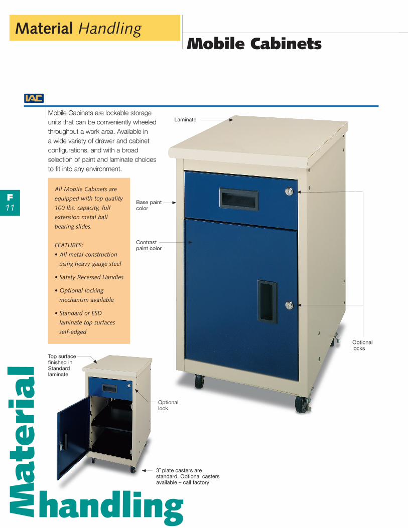
Mobile Cabinets are lockable storage units that can be conveniently wheeled throughout a work area. Available in a wide variety of drawer and cabinet configurations, and with a broad selection of paint and laminate choices to fit into any environment.
Optionallock
3˝ plate casters are standard. Optional casters available – call factory
All Mobile Cabinets are
equipped with top quality
100 lbs. capacity, full
extension metal ball
bearing slides.
FEATURES:
• All metal construction
using heavy gauge steel
• Safety Recessed Handles
• Optional locking
mechanism available
• Standard or ESD
laminate top surfaces
self-edged
Top surface finished in Standard laminate
Optional locks
Base paint color
Contrast paint color
Laminate

Material HandlingM
ate
rialhandling
F12
Mount Part NumberRight-Hand 1050038Left-Hand 2050034
Specify by Part Number based on Drawer/Locker configuration and laminate type used on top – Standard or ESD.
Specify a paint and contrast paint color as separate line items on the order. See colors on page A-14.
Specify a laminate color. See colors on page A-16.
List any options as separate line items on your order.
Call factory for information on alternate casters.
ordering tipsfrom IAC...
Cabinet Options
Four 6˝ drawers
Single 6˝ drawer & 18˝ locker w/shelfExtra Cabinet Shelf – for use
with full 18˝ and 24˝ lockersPart Number
Cylinder LockPart Number
Locking Mechanism – Gang locks all drawers and lockers in cabinet
Double 6˝ drawer & 12˝ file drawer
Full 24˝ locker w/shelf
Double 3˝ drawer, three 6˝ drawers
Four 3˝ drawers, two 6˝ drawers
Double 12˝ file drawer
Eight 3˝ drawers
Double 6˝ drawer & 12˝ locker
Double 3˝ drawer & 18˝ locker w/shelf
Four 3˝ drawers & 12˝ locker
Single 6˝ drawer & 18˝ locker w/shelf
Full 24˝ lockerw/shelf
Double 6˝ drawer & 12˝ locker
Double 12˝ locker
Double 12˝ locker
Double 3˝ drawer & 18˝ locker w/shelf
Four 3˝ drawers & 12˝ locker
Four 3˝ drawers & 12˝ drawer
Left-HandCabinets
Right-HandCabinets
2050031
2050033
2050035
1050606Standard:
1050656ESD:
1050619Standard:
1050669ESD:
1050603Standard:
1050653ESD:
1050612Standard:
1050662ESD:
1050614Standard:
1050664ESD:
1050616Standard:
1050666ESD:
1050604Standard:
1050654ESD:
1050609Standard:
1050659ESD:
1050601Standard:
1050651ESD:
1050617Standard:
1050667ESD:
1050607Standard:
1050657ESD:
1050608Standard:
1050658ESD:
1050610Standard:
1050660ESD:
1050605Standard:
1050655ESD:
1050618Standard:
1050668ESD:
1050602Standard:
1050652ESD:
1050611Standard:
1050661ESD:
1050613Standard:
1050663ESD:
1050615Standard:
1050665ESD:
1
2
3
4
5
Mobile Cabinet Configuration
Master Key SetPart Number
Material HandlingM
ate
rial
handling
F13
Conveyor Systems
Roller Conveyor Systems
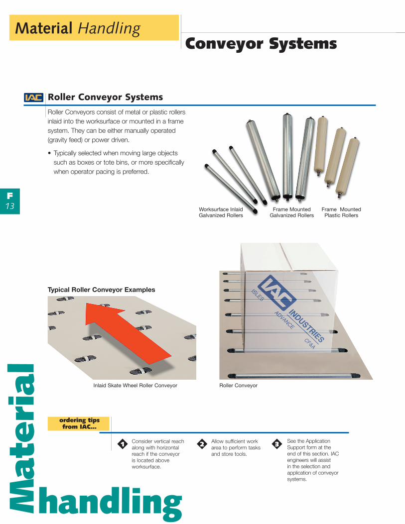
Roller Conveyors consist of metal or plastic rollers inlaid into the worksurface or mounted in a frame system. They can be either manually operated (gravity feed) or power driven.
• Typically selected when moving large objects such as boxes or tote bins, or more specifically when operator pacing is preferred.
1 Consider vertical reach along with horizontal reach if the conveyor is located above worksurface.
2 Allow sufficient work area to perform tasks and store tools.
ordering tipsfrom IAC...
Inlaid Skate Wheel Roller Conveyor Roller Conveyor
Frame Mounted Galvanized Rollers
Frame Mounted Plastic Rollers
Worksurface Inlaid Galvanized Rollers
Typical Roller Conveyor Examples
See the Application Support form at the end of this section. IAC engineers will assist in the selection and application of conveyor systems.
3

Material HandlingM
ate
rialhandling
F14
– Roller Balls
– Brakes
Ball Transfer Systems
Typical Ball Pattern ConfigurationsIAC uses Ball Transfer Systems that have been specifically designed for integration with workstations. Pattern configurations can be customized according to your needs and applications. Consult IAC with your specific requirements.
Ball Transfer Systems use rotating balls seated individually within metal flanged cylinders that are on top or inset into a worksurface.
The balls are made of stainless steel, and have a smooth uniform surface so they can rotate in place easily.
Each ball unit is capable of lifting up to 20 lbs.
There are two types of Ball Transfer Systems• Fixed: designed for simple transport of objects
across the worksurface.• Pneumatic “pop-up” or “retractable”: designed for
applications in which the worksurface sees duty for both transport and as a task work area.
Pop-up Brakes
Pop-up Roller Ball
Pneumatic Actuator – foot operated
Pneumatic Actuator – mounted underneath worksurface
Pattern Examples
See the Application Support form at the end of this section. IAC engineers will assist in the selection and application of conveyor systems.
ordering tipsfrom IAC...

Material HandlingM
ate
rial
handling
F15
Worksurface Pop-Up Ball andRoller Transfer Application Support
All requests for IAC Industries’ engineering support with worksurfaces involving ball patterns and rollers are answered as quickly as possible. Please fill out the information below. This will enable IAC to better understand the application and give a quick and sound solution.
Your Name
Company
Address
Phone Number
Fax Number
E-mail Address Worksurface Information
Type of WorksurfaceNon ESD Laminate ESD LaminateStainless SteelMapleOther
Surface SizeDepth (inches) Length (inches) Height (inches) Straight CurvedOther (please attach drawing)
Delivery MethodConveyorCartManuallyOver Head HoistOther
Material Information
Dimension of Object #1Length Height WidthWeight
Dimension of Object #2 LengthHeightWidthWeight
Bottom MaterialCardboardPlasticMetal Plywood
Bottom MaterialCardboardPlasticMetal Plywood
Bottom ShapeHardFlat SolidUneven
Bottom ShapeHardFlat SolidUneven
Direction and Orientation for the Surface
Object Direction Flow (check all that apply)Object Enters Object Movement Left Right Front Back Turn No Turn
Object ExitsLeft Right Front Back Side to Side Front to Back
Working Position of ObjectCenter of worksurface Object (please specify)
Work Environment (i.e. clean with no grease)
Typical Worksurface Top View
Left Right
Skate wheel metal only Other
Front Position
Back
Pop-Up Ball TransferRoller Conveyor SystemPlastic Galvanized Other
Describe:
Describe:

Material HandlingM
ate
rialhandling
F16
Designing Ball Transfer Patterns
Because ball transfers are modular, they lend themselves to an infinite variety of handling patterns. The three most important things to consider in selecting a pattern that is most practical for the planned application are:
1. Size of the object being transferredSmaller footprints (the carrying pallet or tray, or even the item itself) will require a tighter ball pattern than larger footprints. The goal is to maintain a level surface to stabilize and support the item completely.
2. Weight of the objectEven distribution of the object’s weight, relative to its footprint, aids stability. Ball pattern density, i.e. how closely they are spaced, is calculated based on desired per-square-foot loading.
3. Bottom surface of the objectIf the material of the object, pallet or box that comes in contact with the transfer balls is hard and smooth, it is less likely to “break down” under the weight of the object and the indentation effect of the balls. For example, a plastic bin or tote carrier with a solid, flat bottom is easier to transport at higher weights than a light duty corrugated carton.
IAC’s engineering and ergonomics specialists can recommend a ball transfer system configuration that will meet the demands of your application as well as your requirements for integration with conveyors, workstations, rolling carts, racks, and other material handling equipment.
A ball transfer system is ideally included in the original specifications for a new workstation, although field retrofit is possible. Once an appropriate ball pattern is determined, several other factors come into play:
4. Transfer pathPlan the object’s path and distance in relation to the people using it. Will it be straight, perpendicular, angled or omni-directional? Will more than one person, or some sort of conveyor system, be needed to complete the object’s transfer from one point to the next?
5. Environmental cleanlinessThe system could be damaged if grit and particulates become lodged in the ball wells. Keep the work surface clean and free of small parts that could be swept into the wells and damage the pneumatic air transport system.
6. Sufficient worksurface between ballsIf the ball transfer surface is also used as a work area, plan a pattern that allows a maximum amount of clear surface. Once the balls are retracted, there should be enough solid surface area between them for the worker’s tools and parts.