Embed Size (px)
Citation preview

Master of Architecture ThesisStefan Blignaut
M AT E R I A LE X P L O R AT I O NO F A C H A I R

Stefan Blignaut
A thesis submitted to the Graduate Faculty of Virginia Polytechnic Institute and StateUniversity in partial fulfi llment of the professional degree of
Master of Architecture
May 14th, 2019Blacksburg, Virginia
Hans Rott
Edward Becker
Bill Green
Keywords:
ChairCardboardFiberglassSteelMaterial
M AT E R I A LE X P L O R AT I O NO F A C H A I R

A chair was designed and built through exploration of material and form. Cardboard was chosen as the main material to create the chair. Initially it was paired with concrete and a fi rst study was developed. Cardboard and concrete as materials were too different and did not support each other. Failures in the design and material were noted which informed the next steps of the thesis. Rather than stacking the cardboard, I implemented a quarter iso-grid that required less cardboard, could create more complex forms, and was also able to interface more effectively with other materials. A chair form was designed to be tested. Ultimately, two materials were chosen to compliment the cardboard quarter iso-grid. In the fi rst chair a fi berglass skin was used to cover the cardboard, providing lightweight structural support. The second chair used steel in place of fi berglass. Sections of the cardboard were replaced with steel. The two versions of the chair each had their strengths and weaknesses. The fi berglass was lightweight, strong, and smooth, however it was diffi cult to work with and the cardboard became less apparent as a part of the chair. On the other hand the steel fi t into the quarter iso-grid as a rib element similar to the cardboard making the quarter iso-grid and cardboard more apparent. The steel suffered in strength due to the notches necessary for the quarter iso-grid and had to be reinforced.
A B S T R A C T

C O N T E N T S
Chapter 1 / 06Study Model
Chapter 2 / 11Research
Chapter 3 / 15Design
Chapter 4 / 24Cardboard
Chapter 5 / 34Cardboard + Fiberglass
Chapter 6 / 39Cardboard + Steel
iii

1
C H A P T E R 1
Chapter 1 / Study Model
Study Model
The project began with a half scale model of a chair. The purpose of the model was to test my initial thoughts, observe the successes and failures, and fi nd further direction for the project. As with any project this thesis began with many failures from which I had to learn. Understanding the capabilities of the materials began with this study model and remained a theme throughout the project.
A _ Stacked cardboard, corrugations shown

2
The purpose of the initial study model was to test two materials in order to understand their relationship and structural qualities. The materials chosen for the fi rst model were cardboard and concrete. In preparation for designing the model, two chairs were used as inspiration. The Sponeck Chair, designed by Julia von Sponeck, is a thin, extruded, fi ber reinforced concrete. The thin, yet strong concrete was to be combined with a more fragile material in cardboard. The Wiggle Chair by Frank Gehry uses a layered cardboard approach that strengthens the cardboard while allowing for extruded forms similar to the Sponeck Chair.
Chapter 1 / Study Model
B _ Sponeck Chair, case study
C _ Wiggle Chair, case study

3
A series of sketches were drawn in side elevation to fi nd a form that would incorporate both materials in a manner that the concrete would intersect and support the cardboard. A variety of options were examined with similar characteristics. This led to a C shape intersected by an arc.The concrete was cast and inserted into the cardboard structure which held the concrete in place.
Chapter 1 / Study Model
D _ Sketches in pencil and ink

4Chapter 1 / Study Model
E _ Sketches in pencil

5Chapter 1 / Study Model
F _ Half scale study model

6
C H A P T E R 2Research
The study model revealed issues pertaining to the material combination as well as an unnecessary amount of cardboard used to create a rather simple form. The cardboard was also quite weak for the amount of material. These were concerns that I was able to address through research.
G _ Fiberglass on cardboard quarter iso-grid
7
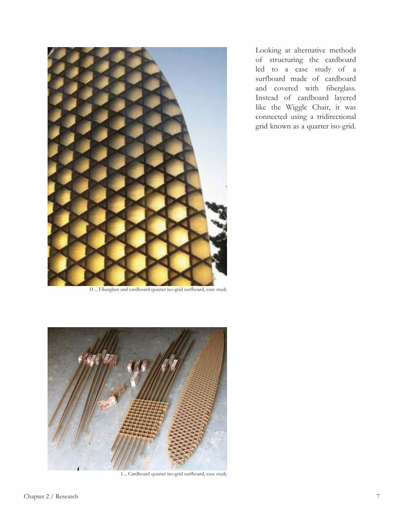
Looking at alternative methods of structuring the cardboard led to a case study of a surfboard made of cardboard and covered with fi berglass. Instead of cardboard layered like the Wiggle Chair, it was connected using a tridirectional grid known as a quarter iso-grid.
Chapter 2 / Research
H _ Fiberglass and cardboard quarter iso-grid surfboard, case study
I _ Cardboard quarter iso-grid surfboard, case study

8
The quarter iso-grid differs from other ribbed structures as it is structurally supported in three directions rather than two. The triangulation stabilizes the structure keeping it from falling over. In order to create the quarter iso-grid, lines are drawn in three directions at 60 degrees to one another. This creates rows of equilateral triangles. Next, three of every 4 triangles are removed as shown in the diagram below. This leaves hexagons in their place and removes any conditions where three lines intersect at one point. This allows the cardboard to be notched in a series of three levels, (top, middle, and bottom) where the middle layer is notched from both the top and bottom.
Chapter 2 / Research
J _ Ribbed model patterns

9Chapter 2 / Research
K _ Fiberglass on cardboard quarter iso-grid test

10
C H A P T E R 3Design
Upon deciding on a system and material set to construct the chair, a form had to be created. I wanted to use a dynamic form that would show off the capabilities of both the materials and the structural system. A lot of back and forth between hand sketching and the computer was necessary to generate such a form. The end result speaks to the power of using computer programs in conjunction with hand drawing.
L _ 3D printed chair model

11
The quarter iso-grid allows for a more dynamic form than the layered cardboard. As a result the form of the chair became important to showcase the quarter iso-grid. Many chairs provided inspiration for the project, but two chairs most effected the design of the chair. The fi rst is a traditional wooden Swedish chair. Handles on the side allow the user to enter and exit the seating position. The slender backrest is reminiscent of throne. Hans Wegner’s Shell Chair is very similar to the Swedish chair. Both have three legs, are tilted up on the sides of the seat, and reclined to be a comfortable lounge chair.
Chapter 3 / Design
M _ Traditional Swedish wooden chair, case study
N _ Hans Wegner’s Shell Chair, case study

12
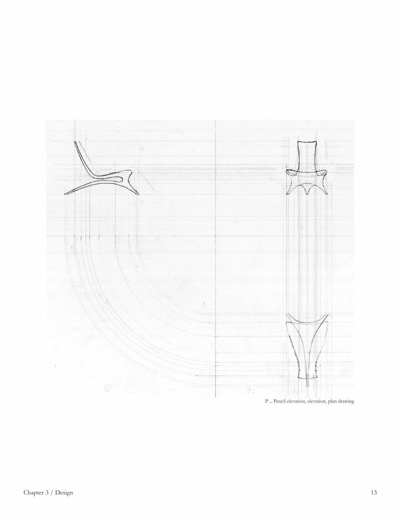
The design began as two arcs curving in opposite directions. Each arc represented a set of elements within the chair. The top arc served as the support for the user in the form of the backrest and the seat, while the bottom arc served to support the chair as the legs. As the form developed the front elevation and top view were resolved. This was just the starting point for the design moving forward. Further changes tightened up the design.
Chapter 3 / Design
O _ Pencil sketches
13Chapter 3 / Design
P _ Pencil elevation, elevation, plan drawing

14
The sketch was scanned and imported to rhino where I began modeling the chair. Once the chair was modeled it was 3D printed in order to examine the form and make decisions on how it needed to be adapted.
Chapter 3 / Design
Q _ First 3D printed model

15
The chair was modifi ed and printed again. The result of the changes was a form that was much closer to the fi nal product, but still required additional changes.
1
Chapter 3 / Design
R _ Second 3D printed model

16
Once the form was decided upon, sketched thoroughly, and 3D printed twice it was important to dimension the chair to fi t the human body. Using Niels Diffrient’s “Humanscale 1, 2, 3” I compared my design to the dimensions recommended as ergonomic for a lounge chair.
Chapter 3 / Design
S _ Humanscale lounge chair seating guide
T _ Ergonomic seating chart

17
After conforming the chair to the recommended dimensions the chair was ready to be sectioned by the quarter is-grid. The result was a fi nal 3D printed model showcasing the cardboard portion of the design.
Chapter 3 / Design
U _ Third 3D printed model

18Chapter 3 / Design
V _ 3D printed model comparison

19
C H A P T E R 4Cardboard
The next step was to generate the quarter iso-grid layers from the model and construct the initial chair completely out of cardboard. I was able to see weak points in the chair where the cardboard needed the most additional strength. The notching process required a grasshopper script to automate the process and create sections to be laser cut. Once the sections were cut, they had to be assembled and the process was documented in still images.
W _ Quarter iso-grid cardboard chair

20
In order to create the chair, the cardboard had to be notched at each intersection. This could be done by hand by fi nding the vertical midpoint at each intersection and cutting a quarter inch notch for both pieces. The notch would be cut halfway up or down according to the intersection. In order to save time, grasshopper was used to automate the notching process. The script below was used to slice the model in the three directions. Once planes were created an intersection line was drawn on each plane. The bottom and top planes were notched in one direction (up and down respectively). While the middle plane was notched in both directions according to which plane it was intersecting.
Chapter 4 / Cardboard
X _ Quarter iso-grid notching diagram
Y _ Grasshopper script

21Chapter 4 / Cardboard
Z _ Notched pieces

22Chapter 4 / Cardboard
AA _ Build sequence
23
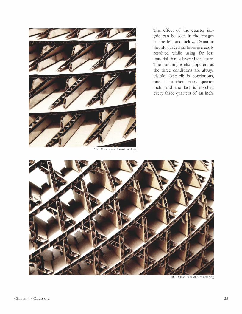
The effect of the quarter iso-grid can be seen in the images to the left and below. Dynamic doubly curved surfaces are easily resolved while using far less material than a layered structure. The notching is also apparent as the three conditions are always visible. One rib is continuous, one is notched every quarter inch, and the last is notched every three quarters of an inch.
Chapter 4 / Cardboard
AB _ Close up cardboard notching
AC _ Close up cardboard notching

24Chapter 4 / Cardboard
AD _ Close up cardboard notching

25
Another interesting effect of the quarter iso-grid is the transparency of the chair. Hexagonal and triagonal voids are left inside the chair that at certain angles allow the user to see straight through the chair to the fl oor. The effect is magnifi ed in the sun when even the corrugations of the cardboard allow light through the chair.
Chapter 4 / Cardboard
AE _ Cardboard quarter iso-grid
AF _ Quarter iso-grid shadow

26
The diagram to the left shows the two main external forces acting upon the chair as the large arrows. The small arrows represent the observed internal reactionary forces. The back leg is the fi rst point of failure in the chair even when no external force is applied. This can be seen in the bottom image. The secondary material must account for these forces and strengthen the chair in the weakest areas. Another weak point is the backrest which has a tendency to break lower down on the back at the fulcrum point created by the user sitting on the chair. Other notable forces are the legs of the chair wanting to move in opposite directions. Also in the middle of the seat the chair begins to bend away from itself.
Chapter 4 / Cardboard
AG _ Force diagram
AH _ Cardboard chair

27Chapter 4 / Cardboard
AI _ Cardboard chair

28Chapter 4 / Cardboard
AJ _ Cardboard chair back
29
C H A P T E R 5Cardboard + Fiberglass
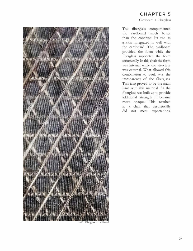
The fi berglass complimented the cardboard much better than the concrete. Its use as a skin integrated it well with the cardboard. The cardboard provided the form while the fi berglass supported the form structurally. In this chair the form was internal while the structure was external. What allowed this combination to work was the transparency of the fi berglass. This also proved to be the main issue with this material. As the fi berglass was built up to provide additional strength it became more opaque. This resulted in a chair that aesthetically did not meet expectations.
AK _ Fiberglass on cardboard
30
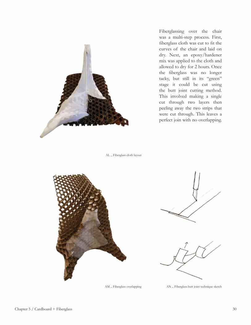
Fiberglassing over the chair was a multi-step process. First, fi berglass cloth was cut to fi t the curves of the chair and laid on dry. Next, an epoxy/hardener mix was applied to the cloth and allowed to dry for 2 hours. Once the fi berglass was no longer tacky, but still in its “green” stage it could be cut using the butt joint cutting method. This involved making a single cut through two layers then peeling away the two strips that were cut through. This leaves a perfect join with no overlapping.
Chapter 5 / Cardboard + Fiberglass
AL _ Fiberglass cloth layout
AM _ Fiberglass overlapping AN _ Fiberglass butt joint technique sketch

31Chapter 5 / Cardboard + Fiberglass
AO _ Fiberglass back

32
The fi berglass creates a rigid outer layer that structurally supports the cardboard inside. The transparency of the fi berglass exposes the cardboard system underneath. This effect is pronounced when light from beneath.
Chapter 5 / Cardboard + Fiberglass
AP _ Fiberglass quarter iso-grid
AQ _ Fiberglass on cardboard

33Chapter 5 / Cardboard + Fiberglass
AR _ Fiberglass chair

34
C H A P T E R 6Cardboard + Steel
In response to the shortcomings of the cardboard and fi berglass, I decided to use steel as the secondary material. This allowed the cardboard to be more apparent in the design as the steel complimented the cardboard structurally and aesthetically. However, this did not come without its own issues. Since the steel was just shy of 1/8th inch thick it had a tendency to bend under force. To alleviate this problem structural supports had to be inserted at various points.
AS _ Cardboard and steel chair

35
Select pieces were chosen to reinforce the cardboard as steel. These steel pieces were laser cut, machined, and hand cut. One piece had to be reinforced. The quarter inch gap was mostly fi lled back in with a strip of steel that was welded in. The bottom strip of the gap was left for the cardboard to slot into. Once all the pieces were cut they could be assembled to make the frame of the chair.
Chapter 6 / Cardboard + Steel
AT _ Cutting metal pieces
AU _ Metal insert AV _ Metal insert

36
For the steel frame to be structurally stable the intersections had to be welded together. In the image shown on the left, a scrap piece of steel was used to practice welds before welding the frame together. Small welding spots were used to tack the steel together. Once the frame was fully welded the welds were sanded and fi led down. The image below shows fi nished welds after being sanded and painted.
Chapter 6 / Cardboard + Steel
AW _ Force diagram
AX _ Welds before grinding AY _ Welds after grinding

37
The image on the left shows the fi nished steel frame. The steel ribs were intended to be minimal. As a result four ribs were selected for the backrest. The two outer ribs help with the integrity of the cardboard on the edges, while the interior ribs support the seat, backrest, and back leg. These ribs were then cross-braced with two ribs on the backrest and two ribs on the seat. The cross braces for the seat also lead into the front legs for structural support. This system braced all three legs while also bracing the backrest and seat. In order to insert the cardboard pieces the middle set was inserted fi rst. This allowed placement of the bottom set and top set in that order with relative ease.
Chapter 6 / Cardboard + Steel
AZ _ Steel frame
BA _ Cardboard slotted in steel

38Chapter 6 / Cardboard + Steel
BB _ Cardboard slotted in steel
39
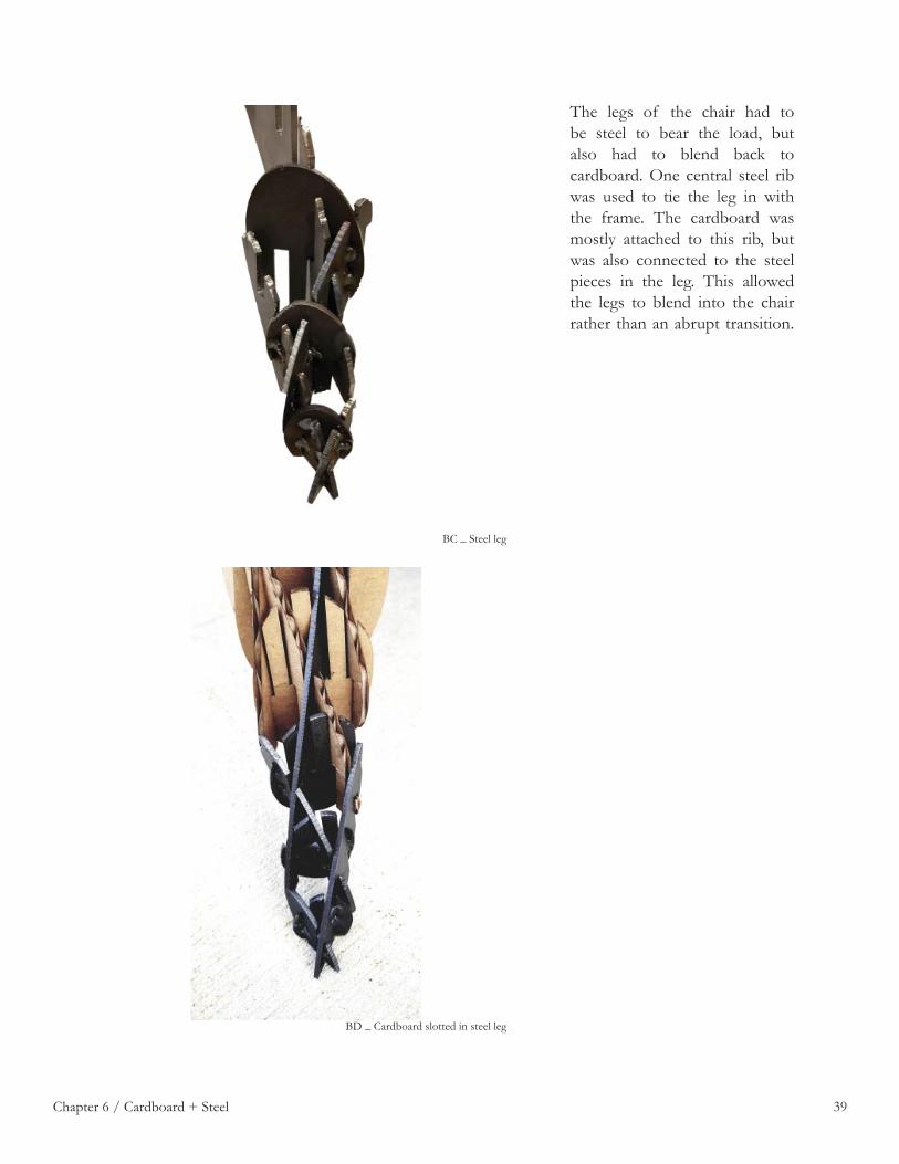
The legs of the chair had to be steel to bear the load, but also had to blend back to cardboard. One central steel rib was used to tie the leg in with the frame. The cardboard was mostly attached to this rib, but was also connected to the steel pieces in the leg. This allowed the legs to blend into the chair rather than an abrupt transition.
Chapter 6 / Cardboard + Steel
BC _ Steel leg
BD _ Cardboard slotted in steel leg

40Chapter 6 / Cardboard + Steel
BE _ Cardboard slotted in steel leg

41Chapter 6 / Cardboard + Steel
BF _ Cardboard and steel front leg

42
The back leg held the majority of the weight of the chair. In order to strengthen the leg more steel pieces were cut allowing the leg to be mostly steel yet still transition elegantly back to cardboard. Furthermore, two 3/8” metal rods were welded using small welding spots to the bottom preventing the leg from fl exing too far.
Chapter 6 / Cardboard + Steel
BG _ Cardboard and steel back leg
BH _ Cardboard and steel back leg

43Chapter 6 / Cardboard + Steel
BI _ Cardboard and steel legs

44
Another necessary structural addition was the placement of cross-bracing for the two main ribs. This kept the ribs from wracking as well as strengthening the weakest point in the chair. Another addition was to add two plates between the back leg and the seat. These connected the steel ribs keeping them from bending as well as strengthening the backrest.
Chapter 6 / Cardboard + Steel
BJ _ Steel supports
BK _ Steel supports

45Chapter 6 / Cardboard + Steel
BL _ Cardboard and steel chair

46
The steel ribs chosen for the edges of the backrest can be seen in the images on this page. A minimal amount of cardboard ribs are allowed to create the edge of the seat. This is to insure the edge does not deteriorate with use. The connection at the top of the backrest connects the cross braces with the edge ribs. This connection was very important in providing rigidity to the backrest as well as protecting the corners.
Chapter 6 / Cardboard + Steel
BM _ Cardboard and steel back
BN _ Cardboard and steel top weld BO _ Cardboard and steel side of backrest

47
I n d ex
A _ Stacked cardboard, corrugations shown / 1B _ Sponeck Chair, case study / 2C _ Wiggle Chair, case study / 2D _ Sketches in pencil and ink / 3E _ Sketches in pencil / 4F _ Half scale study model / 5G _ Fiberglass on cardboard quarter iso-grid / 6H _ Fiberglass and cardboard quarter iso-grid surfboard, case study / 7I _ Cardboard quarter iso-grid surfboard, case study / 7J _ Ribbed model patterns / 8K _ Fiberglass on cardboard quarter iso-grid test / 9L _ 3D printed chair model / 10M _ Traditional Swedish wooden chair, case study / 11N _ Hans Wegner’s Shell Chair, case study / 11O _ Pencil sketches / 12P _ Pencil elevation, elevation, plan drawing / 13Q _ First 3D printed model / 14R _ Second 3D printed model / 15S _ Humanscale lounge chair seating guide / 16T _ Ergonomic seating chart / 16U _ Third 3D printed model / 17V _ 3D printed model comparison / 18W _ Quarter iso-grid cardboard chair / 19X _ Quarter iso-grid notching diagram / 20Y _ Grasshopper script / 20Z _ Notched pieces / 21AA _ Build sequence / 22AB _ Close up cardboard notching / 23AC _ Close up cardboard notching / 23AD _ Close up cardboard notching / 24AE _ Cardboard quarter iso-grid / 25AF _ Quarter iso-grid shadow / 25AG _ Force diagram / 26AH _ Cardboard chair / 26AI _ Cardboard chair / 27AJ _ Cardboard chair back / 28AK _ Fiberglass on cardboard / 29AL _ Fiberglass cloth layout / 30AM _ Fiberglass overlapping / 30AN _ Fiberglass butt joint technique sketch / 30AO _ Fiberglass back / 31AP _ Fiberglass quarter iso-grid / 32AQ _ Fiberglass on cardboard / 32AR _ Fiberglass chair / 33AS _ Cardboard and steel chair / 34AT _ Cutting metal pieces / 35AU _ Metal insert / 35AV _ Metal insert / 35AW _ Force diagram / 36AX _ Welds before grinding / 36AY _ Welds after grinding / 36AZ _ Steel frame / 37BA _ Cardboard slotted in steel / 37BB _ Cardboard slotted in steel / 38BC _ Steel leg / 39BD _ Cardboard slotted in steel leg / 39BE _ Cardboard slotted in steel leg / 40BF _ Cardboard and steel front leg / 41BG _ Cardboard and steel back leg / 42BH _ Cardboard and steel back leg / 42BI _ Cardboard and steel legs / 43BJ _ Steel supports / 44BK _ Steel supports / 44BL _ Cardboard and steel chair / 45BM _ Cardboard and steel back / 46BN _ Cardboard and steel top weld / 46BO _ Cardboard and steel side of backrest / 46

48
C i t a t i o n s
Diffrient, Niels, Alvin R. Tilley, and Joan C. Bardagjy. Humanscale 1/2/3: A Portfolio of Information ; 1 Sizes of People, 2 Seating Considerations, 3 Requirements for the Handicapped and Elderly. Cambridge, MA: MIT Press, 1979.
“Pair of Swedish Three-legged Chairs.” At 1stdibs. Accessed May 29, 2019. https:// www.1stdibs.com/furniture/seating/side-chairs/pair-of-swedish-three- legged-chairs/id-f_766079/.
Quarter Isogrid. Accessed May 29, 2019. https://sheldrake.net/quarter_isogrid/.
“Sponeck Chair Modern Concrete Architectural Design Garden Chair.” Gardenista. Accessed May 29, 2019. https://www.gardenista.com/products/sponeck- chair-modern-concrete-architectural-design-garden-chair/.
Valstir. “Wegner Shell Chair.” Leo Run Home Design. March 25, 2018. Accessed May 29, 2019. http://leoruntoremember.org/wegner-shell-chair/.