Embed Size (px)
Citation preview
Rev. L 8-12-13 MASTERTEMP® Pool and Spa Heater Installation and User’s Guide
1
INSTALLATION AND USER’S GUIDE®MASTERTEMP POOL AND SPA HEATER
DO NOT store or use gasoline or other flammable vapors and liquids in the vicinityof this or other appliances.
FORYOUR
SAFETY
Improper installation, adjustment, alteration, service or maintenance can causepropertydamage, personal injury or death. Installation and service must be performedby a qualified installer, service agency or the gas supplier.
WHAT TO DO IF YOU SMELL GAS• Do not try to light any appliance.• Do not touch any electrical switch; do not use any phone in your building.• Immediately call your gas supplier from a neighbor's phone.
Follow the gas supplier's instructions.• If you cannot reach your gas supplier, call the fire department.
1620 Hawkins Ave., Sanford, NC 27330 • (800) 831-7133 or (919) 566-8000
10951 W. Los Angeles Ave., Moorpark, CA 93021 • (800) 831-7133 or (805) 553-5000
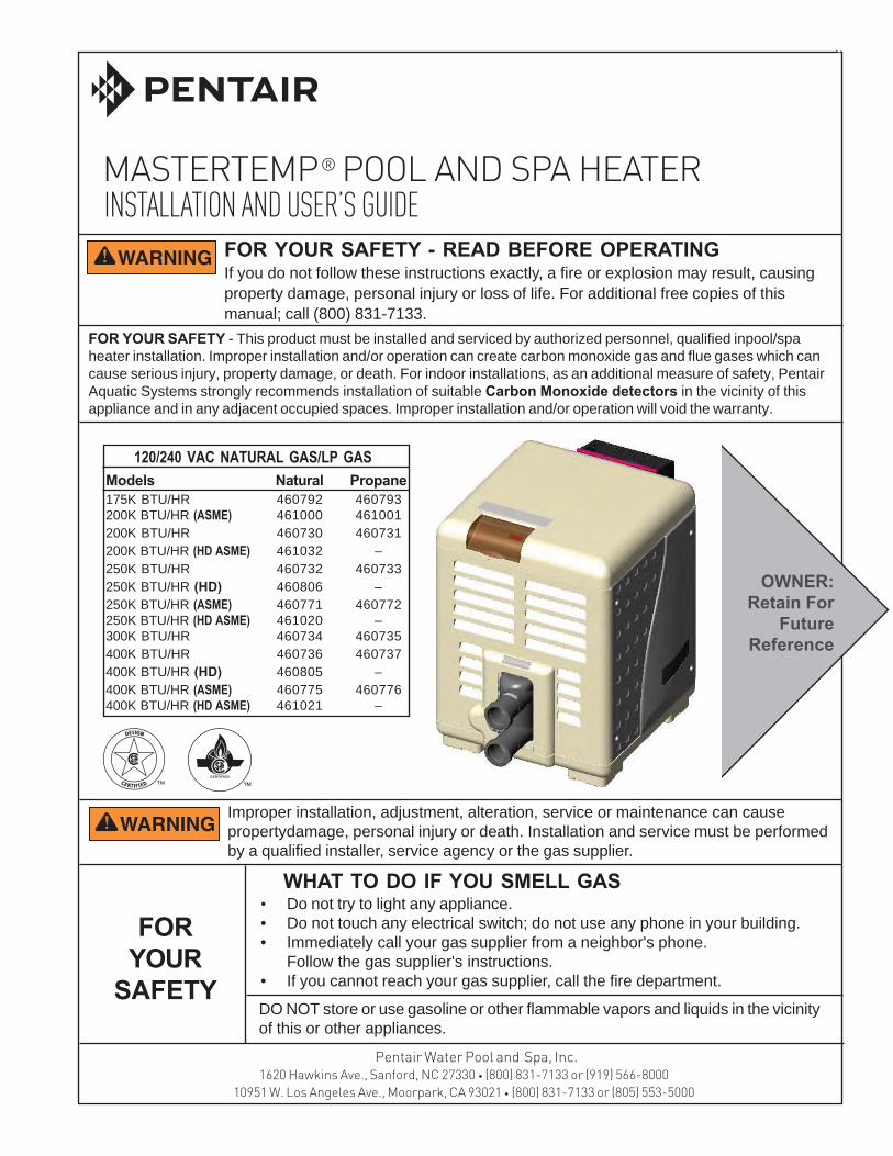
Models Natural Propane175K BTU/HR 460792 460793200K BTU/HR (ASME) 461000 461001200K BTU/HR 460730 460731200K BTU/HR (HD ASME) 461032 –250K BTU/HR 460732 460733250K BTU/HR (HD) 460806 –250K BTU/HR (ASME) 460771 460772250K BTU/HR (HD ASME) 461020 –300K BTU/HR 460734 460735400K BTU/HR 460736 460737400K BTU/HR (HD) 460805 –400K BTU/HR (ASME) 460775 460776400K BTU/HR (HD ASME) 461021 –
FOR YOUR SAFETY - This product must be installed and serviced by authorized personnel, qualified inpool/spaheater installation. Improper installation and/or operation can create carbon monoxide gas and flue gases which cancause serious injury, property damage, or death. For indoor installations, as an additional measure of safety, PentairAquatic Systems strongly recommends installation of suitable Carbon Monoxide detectors in the vicinity of thisappliance and in any adjacent occupied spaces. Improper installation and/or operation will void the warranty.
FOR YOUR SAFETY - READ BEFORE OPERATINGIf you do not follow these instructions exactly, a fire or explosion may result, causingproperty damage, personal injury or loss of life. For additional free copies of thismanual; call (800) 831-7133.
Pentair Water Pool and Spa, Inc.
OWNER:Retain For
FutureReference
120/240 VAC NATURAL GAS/LP GAS
MASTERTEMP® Pool and Spa Heater Installation and User’s Guide Rev. L 8-12-14
2
Customer Service and Tecnincal SupportIf you have questions about ordering Pentair Aquatic Systems replacement parts, and poolproducts, please call:
Phone: (800) 831-7133
Fax: (800) 284-4151(8 A.M. to 4:30 PM Eastern Time/Pacific Time)Web sites: www.pentairpool.com - www.staritepool.com
P/N 472592 Rev. L 8/14
Rev. L 8-12-13 MASTERTEMP® Pool and Spa Heater Installation and User’s Guide
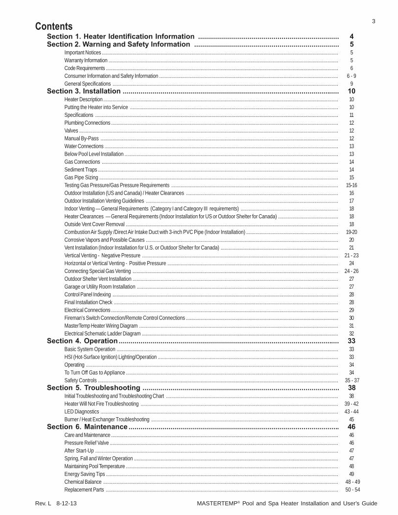
3ContentsSection 1. Heater Identification Information ....................................................................... 4Section 2. Warning and Safety Information ......................................................................... 5
Important Notices ................................................................................................................................................................................. 5Warranty Information ............................................................................................................................................................................ 5Code Requirements .............................................................................................................................................................................. 6Consumer Information and Safety Information ...................................................................................................................................... 6 - 9General Specifications ......................................................................................................................................................................... 9
Section 3. Installation ............................................................................................................. 10Heater Description ................................................................................................................................................................................ 10Putting the Heater into Service ............................................................................................................................................................ 10Specifications ...................................................................................................................................................................................... 11Plumbing Connections .......................................................................................................................................................................... 12Valves .................................................................................................................................................................................................. 12Manual By-Pass .................................................................................................................................................................................. 12Water Connections ............................................................................................................................................................................... 13Below Pool Level Installation ................................................................................................................................................................ 13Gas Connections ................................................................................................................................................................................. 14Sediment Traps .................................................................................................................................................................................... 14Gas Pipe Sizing ................................................................................................................................................................................... 15Testing Gas Pressure/Gas Pressure Requirements ............................................................................................................................. 15-16Outdoor Installation (US and Canada) / Heater Clearances .................................................................................................................. 16Outdoor Installation Venting Guidelines ................................................................................................................................................ 17Indoor Venting — General Requirements (Category I and Category III requirements) ......................................................................... 18Heater Clearances — General Requirements (Indoor Installation for US or Outdoor Shelter for Canada) ............................................. 18Outside Vent Cover Removal ............................................................................................................................................................... 18Combustion Air Supply /Direct Air Intake Duct with 3-inch PVC Pipe (Indoor Installation) ..................................................................... 19-20Corrosive Vapors and Possible Causes ................................................................................................................................................ 20Vent Installation (Indoor Installation for U.S. or Outdoor Shelter for Canada) ........................................................................................ 21Vertical Venting - Negative Pressure ................................................................................................................................................... 21 - 23Horizontal or Vertical Venting - Positive Pressure ................................................................................................................................ 24Connecting Special Gas Venting .......................................................................................................................................................... 24 - 26Outdoor Shelter Vent Installation .......................................................................................................................................................... 27Garage or Utility Room Installation ....................................................................................................................................................... 27Control Panel Indexing ......................................................................................................................................................................... 28Final Installation Check ........................................................................................................................................................................ 28Electrical Connections .......................................................................................................................................................................... 29Fireman’s Switch Connection/Remote Control Connections .................................................................................................................. 30MasterTemp Heater Wiring Diagram ..................................................................................................................................................... 31Electrical Schematic Ladder Diagram ................................................................................................................................................... 32
Section 4. Operation ............................................................................................................... 33Basic System Operation ...................................................................................................................................................................... 33HSI (Hot-Surface Ignition) Lighting/Operation ....................................................................................................................................... 33Operating ............................................................................................................................................................................................. 34To Turn Off Gas to Appliance ............................................................................................................................................................... 34Safety Controls .................................................................................................................................................................................... 35 - 37
Section 5. Troubleshooting ................................................................................................... 38Initial Troubleshooting and Troubleshooting Chart ................................................................................................................................. 38Heater Will Not Fire Troubleshooting .................................................................................................................................................... 39 - 42LED Diagnostics .................................................................................................................................................................................. 43 - 44Burner / Heat Exchanger Troubleshooting ............................................................................................................................................ 45
Section 6. Maintenance .......................................................................................................... 46Care and Maintenance .......................................................................................................................................................................... 46Pressure Relief Valve ........................................................................................................................................................................... 46After Start-Up ...................................................................................................................................................................................... 47Spring, Fall and Winter Operation ......................................................................................................................................................... 47Maintaining Pool Temperature ............................................................................................................................................................... 48Energy Saving Tips .............................................................................................................................................................................. 49Chemical Balance ................................................................................................................................................................................ 48 - 49Replacement Parts .............................................................................................................................................................................. 50 - 54
MASTERTEMP® Pool and Spa Heater Installation and User’s Guide Rev. L 8-12-14
4
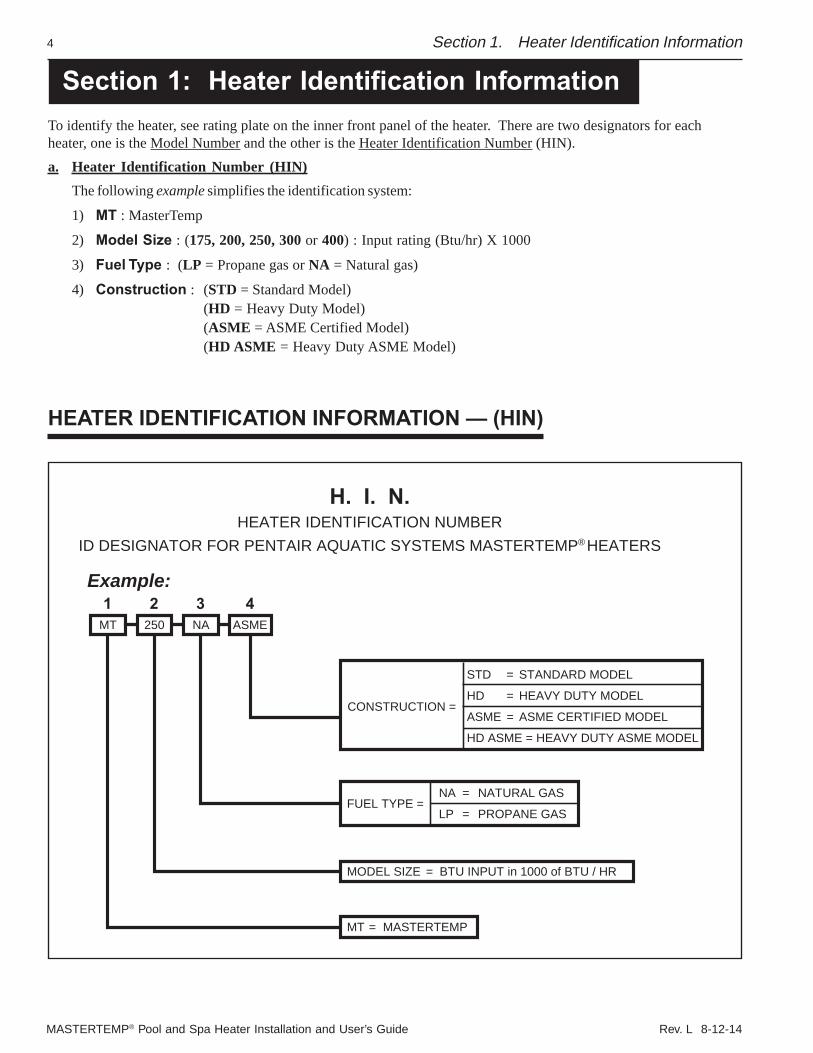
To identify the heater, see rating plate on the inner front panel of the heater. There are two designators for eachheater, one is the Model Number and the other is the Heater Identification Number (HIN).a. Heater Identification Number (HIN)
The following example simplifies the identification system:
1) MT : MasterTemp
2) Model Size : (175, 200, 250, 300 or 400) : Input rating (Btu/hr) X 1000
3) Fuel Type : (LP = Propane gas or NA = Natural gas)
4) Construction : (STD = Standard Model)(HD = Heavy Duty Model)(ASME = ASME Certified Model)(HD ASME = Heavy Duty ASME Model)
Section 1. Heater Identification Information
Section 1: Heater Identification Information
HEATER IDENTIFICATION INFORMATION — (HIN)
MT 250 NA ASME
MT = MASTERTEMP
FUEL TYPE =
CONSTRUCTION =
MODEL SIZE = BTU INPUT in 1000 of BTU / HR
H. I. N.HEATER IDENTIFICATION NUMBER
ID DESIGNATOR FOR PENTAIR AQUATIC SYSTEMS MASTERTEMP HEATERS
STD = STANDARD MODEL
HD = HEAVY DUTY MODEL
ASME = ASME CERTIFIED MODEL
HD ASME = HEAVY DUTY ASME MODEL
NA = NATURAL GAS
LP = PROPANE GAS
Example: 1 2 3 4
®
Rev. L 8-12-13 MASTERTEMP® Pool and Spa Heater Installation and User’s Guide
5
Congratulations on your purchase of the MasterTemp Pool and Spa Heater. Proper installation and service of your newheating system and correct chemical maintenance of the water will ensure years of enjoyment. The MasterTemp heateris a compact, lightweight, efficient, induced-draft, gas fired high performance pool and spa heater that can be directlyconnected to schedule 40 PVC pipe. The MasterTemp heater also comes equipped with the Pentair multifunctiontemperature controller which shows, at a glance, the proper functioning of the heater. All MasterTemp heaters aredesigned with a direct ignition device, HSI (hot-surface ignition), which eliminates the need for a standing pilot. TheMasterTemp heater requires an external power source (120/240 VAC 60 Hz) to operate.SPECIAL INSTRUCTIONS TO OWNER: Retain this manual for future reference. This instruction manual providesoperating instructions, installation and service information for the MasterTemp high performance heater. The informationin this manual applies to all MasterTemp heater models. READ AND REVIEW THIS MANUAL COMPLETELY,it is very important that the owner/installer read and understand the section covering installation instructions, and recognizethe local and state codes before installing the MasterTemp heater. Its use will reduce service calls and chance of injuryand will lengthen product life. History and experience has shown that most heater damage is caused by improper installationpractices.
IMPORTANT NOTICES
For the installer and operator of the MasterTemp heater: The manufacturer’s warranty may be void if, for anyreason, the heater is improperly installed and/or operated. Be sure to follow the instructions set forth in this manual. If youneed any more information, or if you have any questions regarding to this pool heater, please contact Pentair AquaticSystems at (800) 831-7133.
WARRANTY INFORMATION
The MasterTemp pool and spa heater is sold with a limited factory warranty. Specific details are described on thewarranty registration card which is included with the product. Return the warranty registration card after filling inthe serial number from the rating plate inside the heater.
Pentair Aquatic Systems high standards of excellence include a policy of continuous product improvement resultingin your state-of-the-art heater. We reserve the right to make improvements which change the specifications of theheater without incurring an obligation to update the current heater equipment.
These heaters are designed for the heating of chlorine, bromine or salt system swimming pools and spas orin non-stationary installations, and should never be employed for use as space heating boilers or generalpurpose water heaters. The manufacturer’s warranty may be void if, for any reason, the heater is improperlyinstalled and/or operated. Be sure to follow the instructions set forth in this manual.
CAUTIONOPERATING THIS HEATER CONTINUOUSLY AT WATER TEMPERATURE BELOW 68° F. WILL CAUSE HARMFULCONDENSATION AND WILL DAMAGE THE HEATER AND VOID THE WARRANTY. Do not use the heater to protectpools or spas from freezing if the final maintenance temperature desired is below 68° F., as this will cause condensationrelated problems.
Section 2: Warning and Safety InstructionsSection 2. Warning and Safety Instructions
IMPORTANT SAFETY INSTRUCTIONSREAD AND FOLLOW ALL INSTRUCTIONS
SAVE THESE INSTRUCTIONSMASTERTEMP®
Pool and Spa Heater
MASTERTEMP® Pool and Spa Heater Installation and User’s Guide Rev. L 8-12-14
6
CONSUMER INFORMATION AND SAFETY
WARNINGThe U.S. Consumer Product Safety Commission warns that elevated water temperature can be hazardous.See below for water temperature guidelines before setting temperature.
1. Spa or hot tub water temperatures should never exceed 104° F (40° C). A temperature of 100° F (38° C) is considered safe for ahealthy adult. Special caution is suggested for young children.
2. Drinking of alcoholic beverages before or during spa or hot tub use can cause drowsiness which could lead to unconsciousnessand subsequently result in drowning.
3. Pregnant women beware! Soaking in water above 102° F (39° C) can cause fetal damage during the first three months of pregnancy(resulting in the birth of a brain-damaged or deformed child). Pregnant women should stick to the 100° F (38° C) maximum rule.
4. Before entering the spa or hot tub, the user should check the water temperature with an accurate thermometer. Spa or hot tubthermostats may err in regulating water temperatures by as much as 4° F (2.2° C).
5. Persons with a medical history of heart disease, circulatory problems, diabetes or blood pressure problems should obtain theirphysician's advice before using spas or hot tubs.
6. Persons taking medication which induce drowsiness, such as tranquilizers, antihistamines or anticoagulants should not use spasor hot tubs.
WARNINGShould overheating occur or the gas supply fail to shut off, turn off the manual gas control valve to the heater.Do not use this heater if any part has been under water. Immediately call a qualified service technician toinspect the heater and to replace any part of control system and gas control which has been under water.
CODE REQUIREMENTS
Installation must be in accordance with all local codes and/or the latest edition of the National Fuel Gas Code,ANSI Z223.1 and the latest edition of the National Electrical Code, NFPA 70 (US).
Installation in Canada must be in accordance with the latest CAN/CGA-B149.1 or .2 and CSA C22.1 CanadianElectric Code, part 1.
The heater, when installed, must be electrically grounded and bonded in accordance with local codes, or, in absence oflocal codes, with the National Electrical Code, ANSI/NFPA70 (US) or in Canada in accordance with the CanadianElectric Code, part 1.as applicable.
Section 2. Warning and Safety Instructions
DANGERCARBON MONOXIDE GAS IS DEADLY – Exhaust from this pool heater contains toxic levels of carbon monoxide, a dangerous,poisonous gas you cannot see or smell.
Rev. L 8-12-13 MASTERTEMP® Pool and Spa Heater Installation and User’s Guide
7
SAFETY INFORMATION
Section 2. Warning and Safety Instructions
The MasterTemp® pool heaters are designed and manufactured to provide many years of safe and reliable service wheninstalled, operated and maintained according to the information in this manual. Throughout the manual, safety warnings andcautions are identified by the “ “ symbol. Be sure to read and comply with all of the warnings and cautions.
WARNING — This heater is equipped with an unconventional gas control valve that is factory set with amanifold pressure of -.2 inches wc. Improper installation, adjustment, alteration, service ormaintenance can cause property damage, personal injury or loss of life. Installation or service mustbe performed by a qualified installer, service agency or the gas supplier. If this control is replaced, itmust be replaced with an identical control.Do not attempt to adjust the gas flow by adjusting the regulator setting.
CARBON MONOXIDE GAS IS DEADLYREAD OWNERS MANUAL COMPLETELY BEFORE OPERATING
THIS PRODUCT MUST BE INSTALLED AND SERVICED BY A PROFESSIONAL SERVICETECHNICIAN, QUALIFIED IN POOL HEATER INSTALLATION. Some jurisdictions require thatinstallers be licensed. Check with your local building authority about contractor licensing requirements.Improper installation and/or operation could create carbon monoxide gas and flue gases which could causeserious injury or death. Improper installation and/or operation will void the warranty.Exhaust from this pool heater contains toxic levels of carbon monoxide, a dangerous, poisonous gasyou cannot see or smell. Symptoms of carbon monoxide exposure or poisoning include dizziness,headache, nausea, weakness, sleepiness, muscular twitching, vomiting and inability to think clearly.IF YOU EXPERIENCE ANY OF THE ABOVE SYMPTOMS, IMMEDIATELY TURN OFF THE POOLHEATER, LEAVE THE VICINITY OF THE POOL OR SPA AND GET INTO FRESH AIR IMMEDIATELY.THE POOL HEATER MUST BE THOROUGHLY TESTED BY A GAS PROFESSIONAL BEFORERESUMING OPERATION.EXCESSIVE CARBON MONOXIDE EXPOSURE CAN CAUSE BRAIN DAMAGE OR DEATH.NEVER use this pool heater indoors without specified ventilation system (and properly installed vent pipe).NEVER use this pool heater in the home or in partly enclosed areas (such as garages), unlessthe specified ventilation system is used. If used outdoors, install far from open windows, doors,vents and other openings.Pentair strongly recommends that all vents, pipes and exhaust systems be initially and periodicallytested for proper operation. This testing can be accomplished by using a hand-held carbon monoxidemeter and/or by consulting with a gas professional.Pool heaters must be used in conjunction with carbon monoxide detectors installed near the pool heater.The carbon monoxide detectors must be periodically inspected for proper operation so as to insurecontinued safety. Broken or malfunctioning carbon monoxide detectors must be replaced immediately.
DANGER —
WARNING — FOR YOUR SAFETYThis product must be installed and serviced by a professional service technician, qualified in poolheater installation. Some jurisdictions require that installers be licensed. Check with your localbuilding authority about contractor licensing requirements. Improper installation and/or operationcould create carbon monoxide gas and flue gases which could cause serious injury or death. Improperinstallation and/or operation will void the warranty.
MASTERTEMP® Pool and Spa Heater Installation and User’s Guide Rev. L 8-12-14
8 Section 2. Warning and Safety Instructions
SAFETY INFORMATION, (cont’d.)
WARNING — Risk of fire or explosion from incorrect fuel use or faulty fuel conversion. Do not try to run aheater set up for natural gas on propane gas or vice versa. Only qualified service technicians shouldattempt to convert heater from one fuel to the other. Do not attempt to alter the rated input or type ofgas by changing the orifice. If it is necessary to convert to a different type of gas, consult your Pentairdealer. Serious malfunction of the burner can occur which may result in loss of life. Any additions,changes, or conversions required in order for the appliance to satisfactorily meet the applicationneeds must be made by a Pentair dealer or other qualified agency using factory specified andapproved parts. The heater is available for use with natural gas or LP (propane) gas only. It is notdesigned to operate with any other fuels. Refer to the nameplate for the type of gas the heater isequipped to use.• Use heater only with the fuel for which it is designed.
• If a fuel conversion is necessary, refer this work to a qualified service technician or gas supplierbefore putting the heater into operation.
WARNING — Risk of fire or explosion from flammable vapors. Do not store gasoline, cleaning fluids, varnishes,paints, or other volatile flammable liquids near heater or in the same room with heater.
WARNING — Risk of explosion if unit is installed near propane gas storage. Propane (LP) gas is heavierthan air. Consult local codes and fire protection authorities about specific installation requirementsand restrictions. Locate the heater away from propane gas storage and filling equipment as specifiedby the Standard for the Storage and Handling of Liquefied Petroleum Gases, CAN/CSA B149.2(latest edition) or ANSI/NFPA 58 (latest edition).
WARNING — Risk of fire, carbon monoxide poisoning, or asphyxiation if exhaust venting system leaks.Only qualified service technicians should attempt to service the heater, as leakage of exhaustproducts or flammable gas may result from incorrect servicing.
WARNING — Risk of asphyxiation if exhaust is not correctly vented. Follow venting instructions exactlywhen installing heater. Do not use a drafthood with this heater, as the exhaust is underpressure from the burner blower and a draft hood will allow exhaust fumes to blow into the roomhousing the heater. The heater is supplied with an integral venting system for outdoor installation.A vent conversion kit (See Page 24 for Part Numbers for Conversion Kits) is available for installationsin enclosures (Canada) or indoors (U.S.). Use the specified venting, and only the specified venting,when heater is installed in an enclosure or indoors. In Canada, this pool heater can only be installedoutdoors or in an enclosure that is not normally occupied and has no openings directly into occupiedareas. See Page 19 for enclosure venting requirements.
CAUTION — Label all wires prior to disconnection when servicing controls. Wiring errors can causeimproper and dangerous operation. Wiring errors can also destroy the control board.• Connect heater to 120 or 240 Volt, 60 Hz., Single Phase power only.• Verify proper operation after servicing.• Do not allow children to play on or around heater or associated equipment.• Never allow children to use the pool or spa without adult supervision.• Read and follow other safety information contained in this manual prior to operating this pool
heater.
Rev. L 8-12-13 MASTERTEMP® Pool and Spa Heater Installation and User’s Guide
9
GENERAL SPECIFICATIONSNOTICE:
• Combustion air contaminated by corrosive chemical fumes can damage the heater and will void the warranty.
• The Combination Gas Control Valve on this heater differs from most appliance gas controls. If it must be replaced,for safety reasons replace it only with an identical gas control.
• The access door panels must be in place to provide proper ventilation. Do not operate the heater for more than five (5)minutes with the access door panels removed.
• This heater is design certified by CSA International as complying with the Standard for Gas Fired Pool Heaters,ANSI Z21.56/CSA 4.7, and is intended for use in heating fresh water swimming pools or spas.
• The heater is designed for the heating of chlorine, bromine or salt system swimming pools and spas. It should NOT beused as a space heating boiler, or general purpose water heater.
• The heater is design certified by CSA International for installation on combustible flooring. Specified minimumclearances must be maintained to combustible surfaces (see “Heater Clearances”, page 18).
• The heater should be located in an area where leakage of the heater or connections will not result in damage to thearea adjacent to the heater or to the structure. When such locations cannot be avoided, it is recommended that asuitable drain pan, adequately drained, be installed under the heater. The pan must not restrict air flow.
• The heater may not be installed within 5 ft. (1.5M ) of the inside surface of a pool or spa unless it is separated by a solidfence, wall or other permanent barrier.
CONSUMER INFORMATION AND SAFETY
WARNINGThe U.S. Consumer Product Safety Commission warns that carbon monoxide is an "invisible killer". Carbon monoxideis a colorless and odorless gas.
1. Carbon monoxide is produced by burning fuel, including natural gas and propane.
2. Proper installation, operation and maintenance of fuel-burning appliances in the home is the most importantfactor in reducing carbon monoxide poisoning.
3. Be sure that fuel burning appliances such as heaters are installed by professionals according to manufacturer'sinstructions and codes.
4. Always follow the manufacturer's directions for safe operation.
5. Have the heating system (including vents) inspected and serviced annually by a trained service technician.
6. Examine vents regularly for improper connections, visible cracks, rust or stains.
7. Install battery-operated carbon monoxide alarms. The alarms should be certified to the requirements of themost recent UL, IAS, CSA and IAPMO standard for carbon monoxide alarms. Test carbon monoxide alarmsregularly and replace dead batteries.
Section 2. Warning and Safety Instructions
MASTERTEMP® Pool and Spa Heater Installation and User’s Guide Rev. L 8-12-14
10 Section 3. Installation Instructions
Section 3: Installation Instructions
Gas
Air
Mixer
Blower
Inlet(ColdWater)
Exh
aust
Heating CoilsOutlet(MixedWater)
Burner
Figure 1.
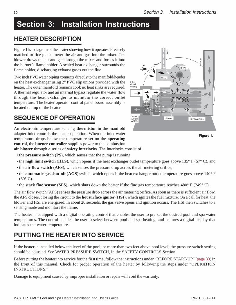
HEATER DESCRIPTIONFigure 1 is a diagram of the heater showing how it operates. Preciselymatched orifice plates meter the air and gas into the mixer. Theblower draws the air and gas through the mixer and forces it intothe burner’s flame holder. A sealed heat exchanger surrounds theflame holder, discharging exhaust gases out the flue.
Two inch PVC water piping connects directly to the manifold/headeron the heat exchanger using 2" PVC slip unions provided with theheater. The outer manifold remains cool; no heat sinks are required.A thermal regulator and an internal bypass regulate the water flowthrough the heat exchanger to maintain the correct outlettemperature. The heater operator control panel board assembly islocated on top of the heater.
SEQUENCE OF OPERATIONAn electronic temperature sensing thermistor in the manifoldadapter inlet controls the heater operation. When the inlet watertemperature drops below the temperature set on the operatingcontrol, the burner controller supplies power to the combustionair blower through a series of safety interlocks. The interlocks consist of:
• the pressure switch (PS), which senses that the pump is running,• the high limit switch (HLS), which opens if the heat exchanger outlet temperature goes above 135° F (57° C), and• the air flow switch (AFS), which senses the pressure drop across the air metering orifice,• the automatic gas shut-off (AGS) switch, which opens if the heat exchanger outlet temperature goes above 140° F
(60° C).• the stack flue sensor (SFS), which shuts down the heater if the flue gas temperature reaches 480° F (249° C).
The air flow switch (AFS) senses the pressure drop across the air metering orifice. As soon as there is sufficient air flow,the AFS closes, closing the circuit to the hot surface igniter (HSI), which ignites the fuel mixture. On a call for heat, theblower and HSI are energized. In about 20 seconds, the gas valve opens and ignition occurs. The HSI then switches to asensing mode and monitors the flame.
The heater is equipped with a digital operating control that enables the user to pre-set the desired pool and spa watertemperatures. The control enables the user to select between pool and spa heating, and features a digital display thatindicates the water temperature.
PUTTING THE HEATER INTO SERVICE
If the heater is installed below the level of the pool, or more than two feet above pool level, the pressure switch settingshould be adjusted. See WATER PRESSURE SWITCH, in the SAFETY CONTROLS Section.
Before putting the heater into service for the first time, follow the instructions under “BEFORE START-UP” (page 33) inthe front of this manual. Check for proper operation of the heater by following the steps under “OPERATIONINSTRUCTIONS.”
Damage to equipment caused by improper installation or repair will void the warranty.
Rev. L 8-12-13 MASTERTEMP® Pool and Spa Heater Installation and User’s Guide
11Section 3. Installation Instructions
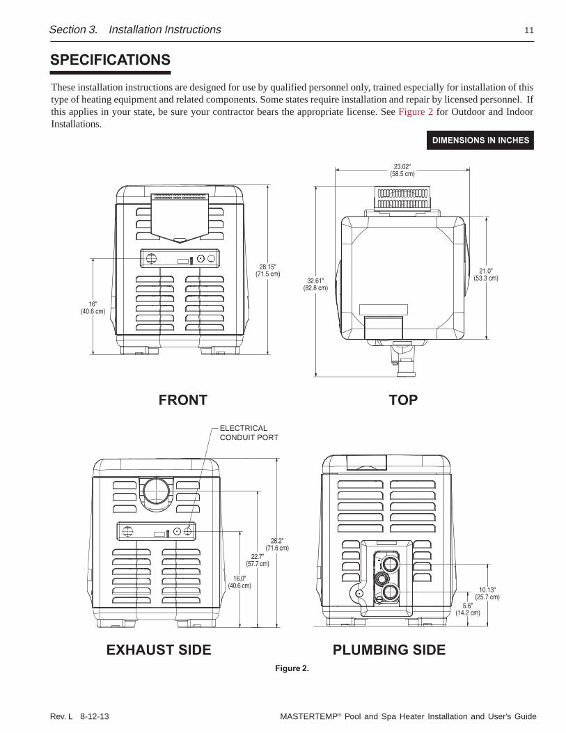
These installation instructions are designed for use by qualified personnel only, trained especially for installation of thistype of heating equipment and related components. Some states require installation and repair by licensed personnel. Ifthis applies in your state, be sure your contractor bears the appropriate license. See Figure 2 for Outdoor and IndoorInstallations.
SPECIFICATIONS
DIMENSIONS IN INCHES
Figure 2.
21.0"(53.3 cm)32.61"
(82.8 cm)
23.02"(58.5 cm)
28.15"(71.5 cm)
16"(40.6 cm)
TOPFRONT
EXHAUST SIDE PLUMBING SIDE
10.13"(25.7 cm)
5.6"(14.2 cm)
ELECTRICALCONDUIT PORT
28.2"(71.6 cm)
22.7"(57.7 cm)
16.0"(40.6 cm)
MASTERTEMP® Pool and Spa Heater Installation and User’s Guide Rev. L 8-12-14
12
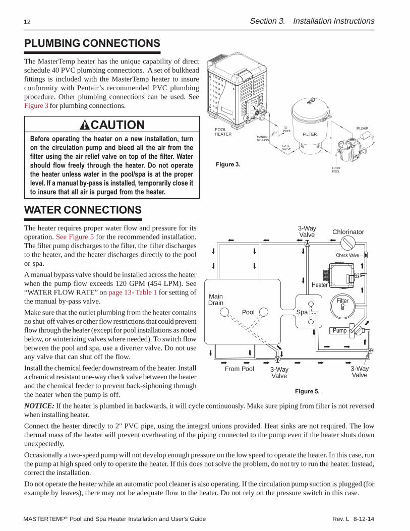
PLUMBING CONNECTIONSThe MasterTemp heater has the unique capability of directschedule 40 PVC plumbing connections. A set of bulkheadfittings is included with the MasterTemp heater to insureconformity with Pentair’s recommended PVC plumbingprocedure. Other plumbing connections can be used. SeeFigure 3 for plumbing connections.
CAUTIONBefore operating the heater on a new installation, turnon the circulation pump and bleed all the air from thefilter using the air relief valve on top of the filter. Watershould flow freely through the heater. Do not operatethe heater unless water in the pool/spa is at the properlevel. If a manual by-pass is installed, temporarily close itto insure that all air is purged from the heater.
WATER CONNECTIONSThe heater requires proper water flow and pressure for itsoperation. See Figure 5 for the recommended installation.The filter pump discharges to the filter, the filter dischargesto the heater, and the heater discharges directly to the poolor spa.A manual bypass valve should be installed across the heaterwhen the pump flow exceeds 120 GPM (454 LPM). See“WATER FLOW RATE” on page 13- Table 1 for setting ofthe manual by-pass valve.Make sure that the outlet plumbing from the heater containsno shut-off valves or other flow restrictions that could preventflow through the heater (except for pool installations as notedbelow, or winterizing valves where needed). To switch flowbetween the pool and spa, use a diverter valve. Do not useany valve that can shut off the flow.Install the chemical feeder downstream of the heater. Installa chemical resistant one-way check valve between the heaterand the chemical feeder to prevent back-siphoning throughthe heater when the pump is off.NOTICE: If the heater is plumbed in backwards, it will cycle continuously. Make sure piping from filter is not reversedwhen installing heater.Connect the heater directly to 2" PVC pipe, using the integral unions provided. Heat sinks are not required. The lowthermal mass of the heater will prevent overheating of the piping connected to the pump even if the heater shuts downunexpectedly.Occasionally a two-speed pump will not develop enough pressure on the low speed to operate the heater. In this case, runthe pump at high speed only to operate the heater. If this does not solve the problem, do not try to run the heater. Instead,correct the installation.Do not operate the heater while an automatic pool cleaner is also operating. If the circulation pump suction is plugged (forexample by leaves), there may not be adequate flow to the heater. Do not rely on the pressure switch in this case.
Pool
MainDrain
Spa
From Pool 3-WayValve
3-WayValve
3-WayValve
Chlorinator
Heater
Pump
Check Valve
Filter
Figure 5.
PUMPFILTER
POOLHEATER
MANUALBY-PASS
TOPOOL
GATEVALVE
FROMPOOL
Section 3. Installation Instructions
Figure 3.
Rev. L 8-12-13 MASTERTEMP® Pool and Spa Heater Installation and User’s Guide
13
BELOW POOL LEVEL INSTALLATIONIf the heater is below water level, the pressure switch must be adjusted. This adjustment must be done by a qualifiedservice technician. See following CAUTION before installation.
CAUTIONBELOW OR ABOVE POOL INSTALLATION
The water pressure switch is set in the factory at 3.00 PSI (± 0.75 PSI). This setting is for a heater installed at pool level.If the heater is to be installed more than 1’ above or below, the water pressure switch must be adjusted by a qualifiedservice technician. See page 35, Figure 29.
FLOW SWITCHIf the heater is installed more than 5’ above the pool or more than 4’ below the pool level, you will be beyond the limitsof the pressure switch and a flow switch must be installed. Locate and install the flow switch externally on the outletpiping from the heater, as close as possible to the heater. Connect the flow switch wires in place of the waterpressure switch wires.
Section 3. Installation Instructions
VALVESWhen any equipment is located below the surface of the pool or spa, valves should be placed in the circulation pipingsystem to isolate the equipment from the pool or spa. Check valves are recommended to prevent back-siphoning. Back-siphoning is most likely to occur when the pump stops, creating a pressure-suction differential. Do NOT sanitize the poolby putting chlorine tablets or sticks into the skimmer(s). When the pump is off, this will cause a high concentration ofchlorine to enter the heater, which could cause corrosion damage to the heat exchanger.
CAUTIONExercise care when installing chemical feeders so as to not allow back siphoning of chemical into the heater, filtersor pump. When chemical feeders are installed in the circulation of the piping system, make sure the feeder outlet lineis down stream of the heater, and is equipped with a positive seal noncorrosive “Check Valve”, (P/N R172288),between the feeder and heater.
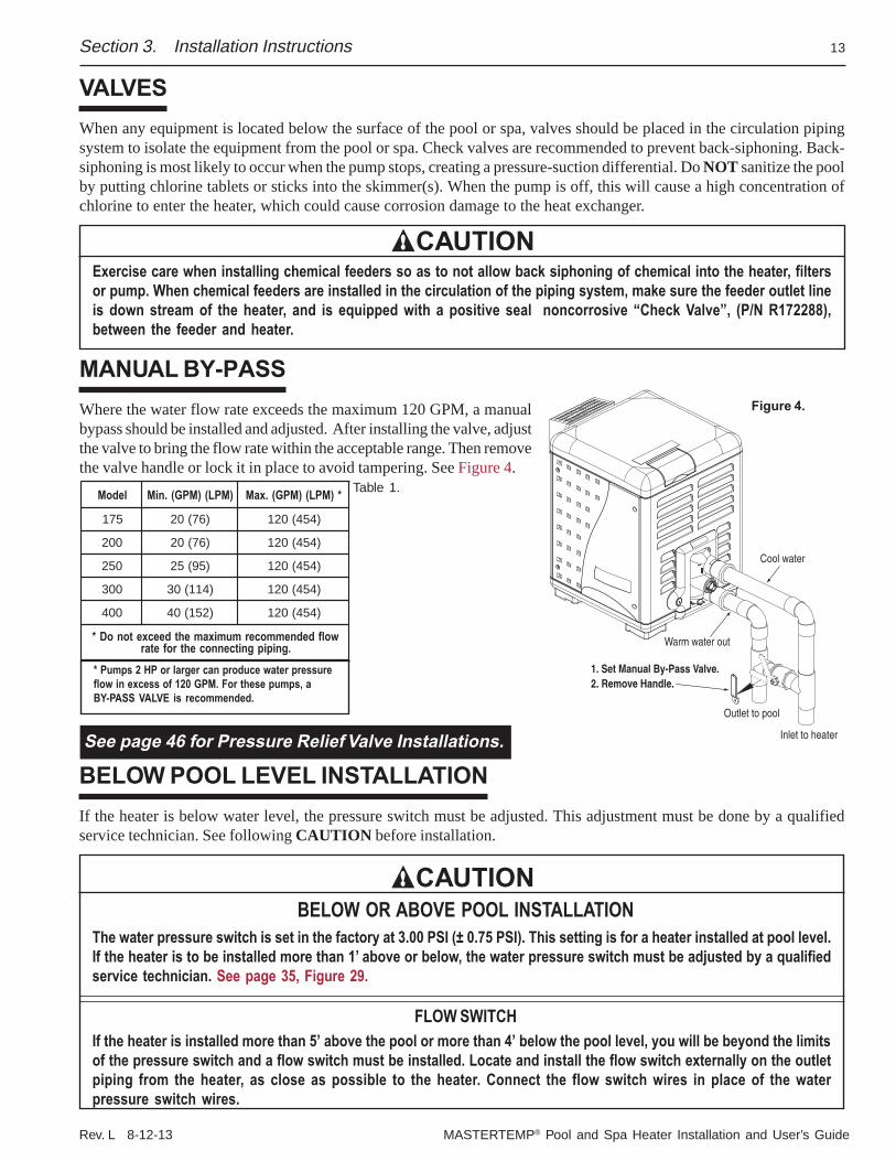
MANUAL BY-PASSWhere the water flow rate exceeds the maximum 120 GPM, a manualbypass should be installed and adjusted. After installing the valve, adjustthe valve to bring the flow rate within the acceptable range. Then removethe valve handle or lock it in place to avoid tampering. See Figure 4.
Table 1.
See page 46 for Pressure Relief Valve Installations.
ledoM )MPL()MPG(.niM *)MPL()MPG(.xaM
571 )67(02 )454(021
002 )67(02 )454(021
052 )59(52 )454(021
003 )411(03 )454(021
004 )251(04 )454(021
wolfdednemmocermumixamehtdeecxetonoD*.gnipipgnitcennocehtrofetar
Cool water
Warm water out
Outlet to pool
Inlet to heater
1. Set Manual By-Pass Valve.2. Remove Handle.
Figure 4.
* Pumps 2 HP or larger can produce water pressureflow in excess of 120 GPM. For these pumps, aBY-PASS VALVE is recommended.
MASTERTEMP® Pool and Spa Heater Installation and User’s Guide Rev. L 8-12-14
14
GAS CONNECTIONS
GAS LINE INSTALLATIONSBefore installing the gas line, be sure to check which gas the heater has been designed to burn. This is important becausedifferent types of gas require different gas pipe sizes. The rating plate on the heater will indicate which gas the heater isdesigned to burn. The Table 2, shown on page 15, show which size pipe is required for the distance from the gas meter tothe heater. The table is for natural gas at a specific gravity of .65 and propane at a specific gravity of 1.55.
When sizing gas lines, calculate three (3) additional feet of straight pipe for every elbow used. When installing the gas line,avoid getting dirt, grease or other foreign material in the pipe as this may cause damage to the gas valve, which may resultin heater failure.
The gas meter should be checked to make sure that it will supply enough gas to the heater and any other appliancesthat may be used on the same meter. The gas line from the meter will usually be of a larger size than the gas valvesupplied with the heater. Therefore a reduction of the connecting gas pipe will be necessary. Make this reductionas close to the heater as possible.
The heater requires a gas supply of not less than 4" (10.2 cm) wc and not more than 14" (35.6 cm) wc. Gas supplypressures outside of this range may result in improper burner operation. A minimum flowing or dynamic inlet pressure(while the heater is running) of 4" (10.2cm) wc is required to maintain input rating with no more than a 2” pressure dropbetween static and dynamic. The gas supply must be installed in accordance with the National Fuel Gas Code,ANSIZ223.1, or standard CSA B149.1, Natural Gas and Propane Installation Codes, as applicable and all applicablelocal codes. Install a manual shut-off valve and a sediment trap and union located outside the heater panels, see Figure 6.Do not use a restrictive gas cock. The following minimum gas pipe sizes are recommended for natural gas supply piping,see Table 2 on page 15. For low pressure LP gas, pipe size may be reduced by 1/4", with a minimum pipe size of 1/2".Check for compliance with local codes.
The heater and any other gas appliances must be disconnected from the gas supply piping system during any pressuretesting on that system, (greater than ½ PSI). The heater and its gas connection must be leak tested before placing theheater in operation. Do not use flame to test the gas line. Use soapy water or another nonflammable method.
NOTEA manual main shut-off valve must be installed externally to the heater.
WARNINGDO NOT INSTALL THE GAS LINE UNION INSIDE THE HEATER CABINET. THIS WILL VOID YOUR WARRANTY.
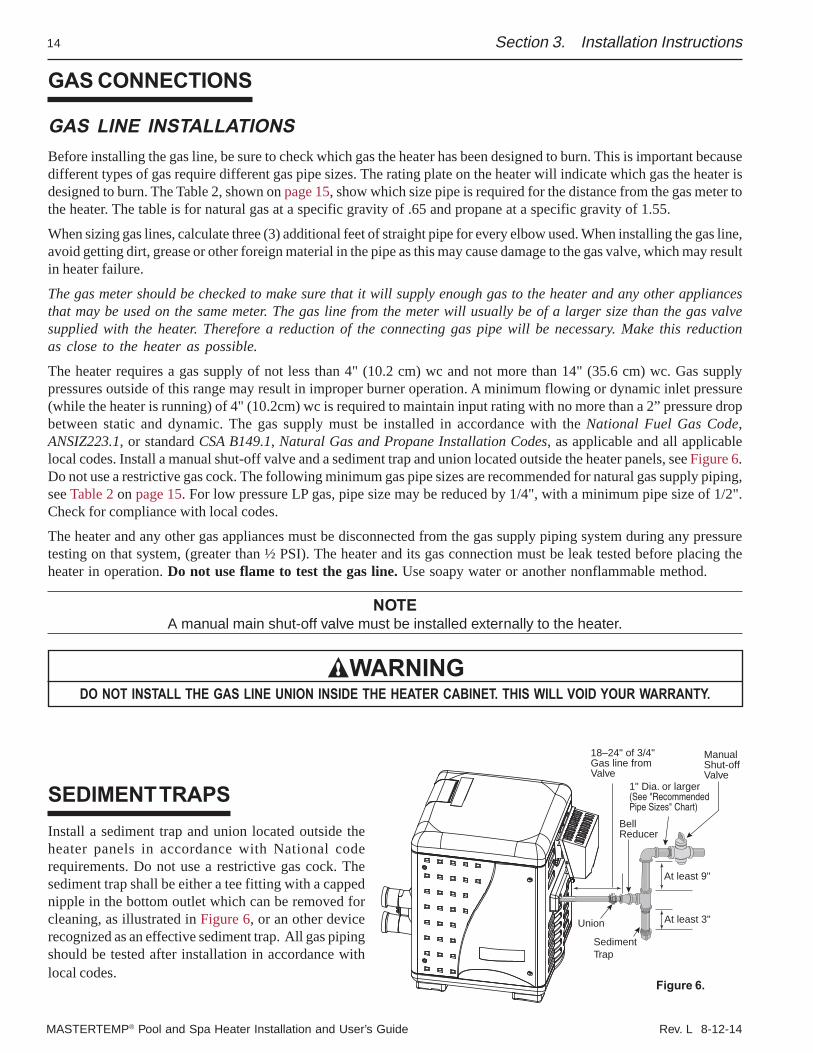
SEDIMENT TRAPSInstall a sediment trap and union located outside theheater panels in accordance with National coderequirements. Do not use a restrictive gas cock. Thesediment trap shall be either a tee fitting with a cappednipple in the bottom outlet which can be removed forcleaning, as illustrated in Figure 6, or an other devicerecognized as an effective sediment trap. All gas pipingshould be tested after installation in accordance withlocal codes.
Figure 6.
Section 3. Installation Instructions
ManualShut-offValve
SedimentTrap
Union
At least 9"
At least 3"
1" Dia. or larger(See "RecommendedPipe Sizes" Chart)
18–24" of 3/4"Gas line fromValve
BellReducer
Rev. L 8-12-13 MASTERTEMP® Pool and Spa Heater Installation and User’s Guide
15
GAS PIPE SIZING
Table 2.
Section 3. Installation
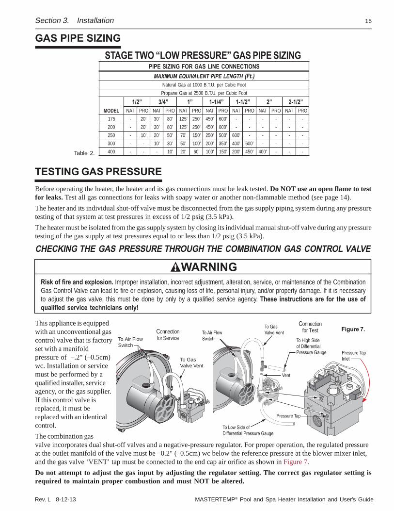
SNOITCENNOCENILSAGROFGNIZISEPIPHTGNELEPIPTNELAVIUQEMUMIXAM ).tF(
tooFcibuCrep.U.T.B0001tasaGlarutaNtooFcibuCrep.U.T.B0052tasaGenaporP
LEDOM”2/1 ”4/3 ”1 ”4/1-1 ”2/1-1 ”2 ”2/1-2
TAN ORP TAN ORP TAN ORP TAN ORP TAN ORP TAN ORP TAN ORP571 - ’02 ’03 ’08 ’521 ’052 ’054 ’006 - - - - - -002 - ’02 ’03 ’08 ’521 ’052 ’054 ’006 - - - - - -052 - ’01 ’02 ’05 ’07 ’051 ’052 ’005 ’006 - - - - -003 - - ’01 ’03 ’05 ’001 ’002 ’053 ’004 ’006 - - - -004 - - - ’01 ’02 ’06 ’001 ’051 ’002 ’054 ’004 - - -
STAGE TWO “LOW PRESSURE” GAS PIPE SIZING
Before operating the heater, the heater and its gas connections must be leak tested. Do NOT use an open flame to testfor leaks. Test all gas connections for leaks with soapy water or another non-flammable method (see page 14).The heater and its individual shut-off valve must be disconnected from the gas supply piping system during any pressuretesting of that system at test pressures in excess of 1/2 psig (3.5 kPa).The heater must be isolated from the gas supply system by closing its individual manual shut-off valve during any pressuretesting of the gas supply at test pressures equal to or less than 1/2 psig (3.5 kPa).
CHECKING THE GAS PRESSURE THROUGH THE COMBINATION GAS CONTROL VALVE
WARNINGRisk of fire and explosion. Improper installation, incorrect adjustment, alteration, service, or maintenance of the CombinationGas Control Valve can lead to fire or explosion, causing loss of life, personal injury, and/or property damage. If it is necessaryto adjust the gas valve, this must be done by only by a qualified service agency. These instructions are for the use ofqualified service technicians only!
This appliance is equippedwith an unconventional gascontrol valve that is factoryset with a manifoldpressure of –.2" (–0.5cm)wc. Installation or servicemust be performed by aqualified installer, serviceagency, or the gas supplier.If this control valve isreplaced, it must bereplaced with an identicalcontrol.The combination gasvalve incorporates dual shut-off valves and a negative-pressure regulator. For proper operation, the regulated pressureat the outlet manifold of the valve must be –0.2" (–0.5cm) wc below the reference pressure at the blower mixer inlet,and the gas valve ‘VENT’ tap must be connected to the end cap air orifice as shown in Figure 7.Do not attempt to adjust the gas input by adjusting the regulator setting. The correct gas regulator setting isrequired to maintain proper combustion and must NOT be altered.
TESTING GAS PRESSURE
To Air FlowSwitch
To GasValve Vent
Vent
Pressure Tap
To High Sideof DifferentialPressure Gauge
To Low Side ofDifferential Pressure Gauge
Pressure TapInlet
Figure 7.To Air FlowSwitch
To GasValve Vent
Connectionfor Service
Connectionfor Test
MASTERTEMP® Pool and Spa Heater Installation and User’s Guide Rev. L 8-12-14
16
HEATER CLEARANCES – OUTDOOR
IMPORTANT!• In an outdoor installation it is important to ensure water is diverted from overhanging eves with a proper
gutter/drainage system. The heater must be set on a level foundation for proper drainage.• This unit shall not be operated outdoors at temperatures below -20o F.
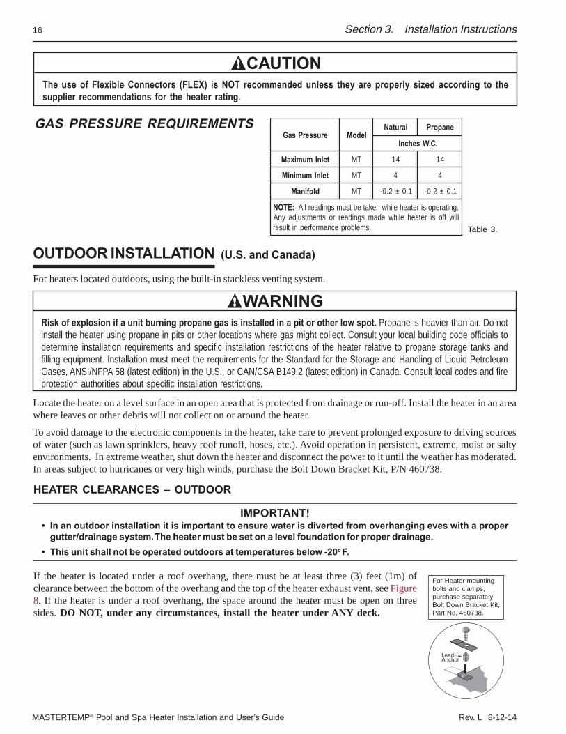
If the heater is located under a roof overhang, there must be at least three (3) feet (1m) ofclearance between the bottom of the overhang and the top of the heater exhaust vent, see Figure8. If the heater is under a roof overhang, the space around the heater must be open on threesides. DO NOT, under any circumstances, install the heater under ANY deck.
(U.S. and Canada)
LeadAnchor
For Heater mountingbolts and clamps, purchase separatelyBolt Down Bracket Kit, Part No. 460738.
Section 3. Installation Instructions
Table 3.
CAUTIONThe use of Flexible Connectors (FLEX) is NOT recommended unless they are properly sized according to thesupplier recommendations for the heater rating.
GAS PRESSURE REQUIREMENTSerusserPsaG ledoM
larutaN enaporP
.C.WsehcnI
telnImumixaM TM 41 41
telnImuminiM TM 4 4
dlofinaM TM 1.0±2.0- 1.0±2.0-
:ETON .gnitareposiretaehelihwnekatebtsumsgnidaerllAlliwffosiretaehelihwedamsgnidaerrostnemtsujdaynA
.smelborpecnamrofrepnitluser
OUTDOOR INSTALLATIONFor heaters located outdoors, using the built-in stackless venting system.
WARNINGRisk of explosion if a unit burning propane gas is installed in a pit or other low spot. Propane is heavier than air. Do notinstall the heater using propane in pits or other locations where gas might collect. Consult your local building code officials todetermine installation requirements and specific installation restrictions of the heater relative to propane storage tanks andfilling equipment. Installation must meet the requirements for the Standard for the Storage and Handling of Liquid PetroleumGases, ANSI/NFPA 58 (latest edition) in the U.S., or CAN/CSA B149.2 (latest edition) in Canada. Consult local codes and fireprotection authorities about specific installation restrictions.
Locate the heater on a level surface in an open area that is protected from drainage or run-off. Install the heater in an areawhere leaves or other debris will not collect on or around the heater.
To avoid damage to the electronic components in the heater, take care to prevent prolonged exposure to driving sourcesof water (such as lawn sprinklers, heavy roof runoff, hoses, etc.). Avoid operation in persistent, extreme, moist or saltyenvironments. In extreme weather, shut down the heater and disconnect the power to it until the weather has moderated.In areas subject to hurricanes or very high winds, purchase the Bolt Down Bracket Kit, P/N 460738.
Rev. L 8-12-13 MASTERTEMP® Pool and Spa Heater Installation and User’s Guide
17Section 3. Installation Instructions
3 ft. (1 M) or more
Figure 8.
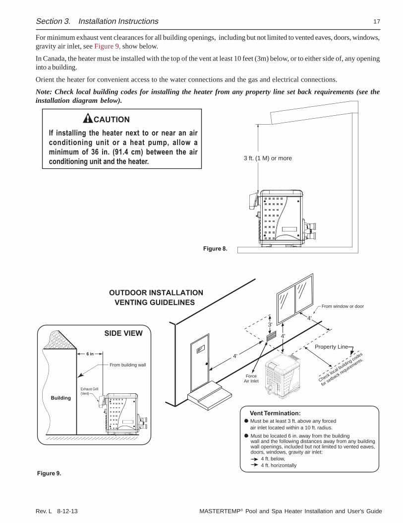
For minimum exhaust vent clearances for all building openings, including but not limited to vented eaves, doors, windows,gravity air inlet, see Figure 9, show below.
In Canada, the heater must be installed with the top of the vent at least 10 feet (3m) below, or to either side of, any openinginto a building.
Orient the heater for convenient access to the water connections and the gas and electrical connections.
Note: Check local building codes for installing the heater from any property line set back requirements (see theinstallation diagram below).
If installing the heater next to or near an airconditioning unit or a heat pump, allow aminimum of 36 in. (91.4 cm) between the airconditioning unit and the heater.
CAUTION
VENTING GUIDELINESOUTDOOR INSTALLATION
Check local building codes
for setback requirements.
ForceAir Inlet
Property Line
4'
4'
4'3'
SIDE VIEW
Building
From building wall
Exhaust Grill(Vent)
6 in
From window or door
Must be at least 3 ft. above any forced air inlet located within a 10 ft. radius.
Vent Termination:
Must be located 6 in. away from the buildingwall and the following distances away from any building wall openings, included but not limited to vented eaves, doors, windows, gravity air inlet:
4 ft. below, 4 ft. horizontally
Figure 9.
MASTERTEMP® Pool and Spa Heater Installation and User’s Guide Rev. L 8-12-14
18
INDOOR VENTING — General Requirements
The heater may be installed as a Category I or Category III appliance.
Vented Appliance (Category I) – Vertical only
An appliance that operates with a nonpositive vent static pressure and with a vent gas temperature that avoids excessivecondensate production in the vent, see pages 20-23.
Vented Appliance (Category III) – Vertical or Horizontal
An appliance that operates with a positive vent static pressure and with a vent gas temperature that avoids excessivecondensate production in the vent, see pages 24-26.
If you are considering connecting this heater to a pre-existing vent system, make sure that the vent system meets theappropriate venting requirements as given in this manual on pages 18-28. If not, replace the vent system. DO NOT usea draft hood with this heater.The MasterTemp heaters are capable of a 270-degree discharge rotation and operate with a positive vent static pressureand with a vent gas temperature less than 400° F (204° C). The total length of the horizontal run must not exceed the lengththat is listed in Table 11 on page 21-22.
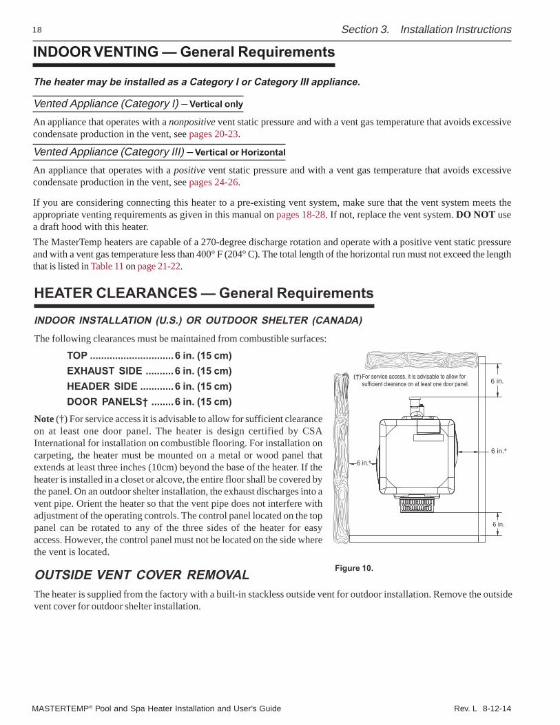
6 in.*
6 in.*
6 in.
6 in.For service access, it is advisable to allow forsufficient clearance on at least one door panel.
Figure 10.
Section 3. Installation Instructions
HEATER CLEARANCES — General Requirements
INDOOR INSTALLATION (U.S.) OR OUTDOOR SHELTER (CANADA)
The following clearances must be maintained from combustible surfaces:
TOP ..............................6 in. (15 cm)EXHAUST SIDE ..........6 in. (15 cm)HEADER SIDE ............6 in. (15 cm)DOOR PANELS† ........6 in. (15 cm)
Note (†) For service access it is advisable to allow for sufficient clearanceon at least one door panel. The heater is design certified by CSAInternational for installation on combustible flooring. For installation oncarpeting, the heater must be mounted on a metal or wood panel thatextends at least three inches (10cm) beyond the base of the heater. If theheater is installed in a closet or alcove, the entire floor shall be covered bythe panel. On an outdoor shelter installation, the exhaust discharges into avent pipe. Orient the heater so that the vent pipe does not interfere withadjustment of the operating controls. The control panel located on the toppanel can be rotated to any of the three sides of the heater for easyaccess. However, the control panel must not be located on the side wherethe vent is located.
OUTSIDE VENT COVER REMOVALThe heater is supplied from the factory with a built-in stackless outside vent for outdoor installation. Remove the outsidevent cover for outdoor shelter installation.

Rev. L 8-12-13 MASTERTEMP® Pool and Spa Heater Installation and User’s Guide
19Section 3. Installation Instructions
*gninepOhcaErofaerAnepOeerFteNmuminiM)sretemitneC/sehcnIerauqS(
ledoMgnidliuBedisnImorFriAllA gnidliuBedistuOmorFriAllA
noitsubmoC tneV noitsubmoC tneV
571 .ni.qs002.mc.qs0921
.ni.qs002.mc.qs0921
.ni.qs05.mc.qs323
.ni.qs05.mc.qs323
002 .ni.qs002.mc.qs0921
.ni.qs002.mc.qs0921
.ni.qs05.mc.qs323
.ni.qs05.mc.qs323
052 .ni.qs052.mc.qs3161
.ni.qs052.mc.qs3161
.ni.qs36.mc.qs604
.ni.qs36.mc.qs604
003 .ni.qs003.mc.qs5391
.ni.qs003.mc.qs5391
.ni.qs57.mc.qs484
.ni.qs57.mc.qs484
004 .ni.qs004.mc.qs0852
.ni.qs004.mc.qs0852
.ni.qs001.mc.qs546
.ni.qs001.mc.qs546
* .gniliecehttaenodnalevelroolftaeno;sgninepoowtfoenorofsidetacidniaerA
COMBUSTION AIR SUPPLYFor indoor installation, the heater location must provide sufficient air supply for proper combustion and ventilation of thesurrounding area.
The minimum requirements for the air supply specify that the room in which a heater is installed should be provided withtwo permanent air supply openings; one within 12 inches (30cm) of the ceiling, the other within 12 inches (30cm) of thefloor for combustion air, in accordance with the latest edition of ANSI Z223.1, or the National Fuel Gas code, the CSAB149.1, Natural Gas and Propane Installation Codes, as applicable, and any local codes that may apply. These openingsshall directly, or through duct, connect to outdoor air.
Note: For indoor installations where combustion air might be insufficient, see “Direct Air Intake Ductwith 3-inch PVC Pipe (Indoor Installation)” below.
Table 4.
Air Supply Requirements Guidefor MasterTemp Heaters
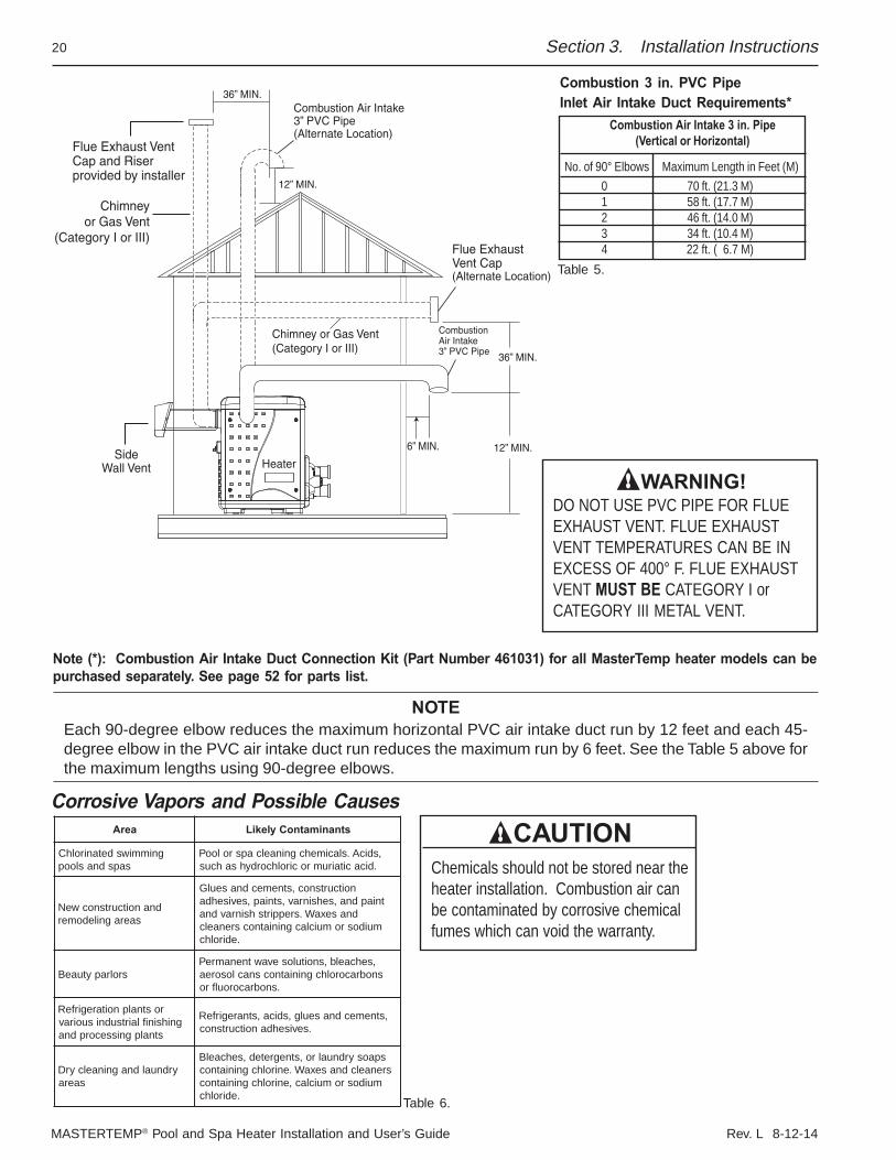
Direct Air Intake Duct with 3-inch PVC Pipe (Indoor Installation)For indoor heater installations where combustion air supply might be insufficient, the MasterTemp® Heater is certified fora direct air intake duct using 3-inch PVC pipe. If outside air is drawn through 3” PVC duct directly into the heater, PVCpipe can be installed in accordance with the following requirements:The air intake opening MUST be installed at least 1 ft. above the roof line or normal snow levels for free air flow. TheCategory I or III exhaust vent termination cap must have at least 3 ft. minimum vertical clearance from air intake duct.(See diagram on page 20).
MASTERTEMP® Pool and Spa Heater Installation and User’s Guide Rev. L 8-12-14
20
Corrosive Vapors and Possible Causes
Section 3. Installation Instructions
Table 6.
aerA stnanimatnoCylekiL
gnimmiwsdetanirolhCsapsdnasloop
,sdicA.slacimehcgninaelcapsrolooP.dicacitairumrocirolhcordyhsahcus
dnanoitcurtsnocweNsaeragniledomer
noitcurtsnoc,stnemecdnaseulGtniapdna,sehsinrav,stniap,sevisehda
dnasexaW.sreppirtshsinravdnamuidosromuiclacgniniatnocsrenaelc
.edirolhc
srolrapytuaeB,sehcaelb,snoitulosevawtnenamrePsnobracorolhcgniniatnocsnaclosorea
.snobracoroulfro
rostnalpnoitaregirfeRgnihsiniflairtsudnisuoirav
stnalpgnissecorpdna
,stnemecdnaseulg,sdica,stnaregirfeR.sevisehdanoitcurtsnoc
yrdnualdnagninaelcyrDsaera
spaosyrdnualro,stnegreted,sehcaelBsrenaelcdnasexaW.enirolhcgniniatnoc
muidosromuiclac,enirolhcgniniatnoc.edirolhc
NOTEEach 90-degree elbow reduces the maximum horizontal PVC air intake duct run by 12 feet and each 45-degree elbow in the PVC air intake duct run reduces the maximum run by 6 feet. See the Table 5 above forthe maximum lengths using 90-degree elbows.
CAUTIONChemicals should not be stored near theheater installation. Combustion air canbe contaminated by corrosive chemicalfumes which can void the warranty.
WARNING!DO NOT USE PVC PIPE FOR FLUEEXHAUST VENT. FLUE EXHAUSTVENT TEMPERATURES CAN BE INEXCESS OF 400° F. FLUE EXHAUSTVENT MUST BE CATEGORY I orCATEGORY III METAL VENT.
Note (*): Combustion Air Intake Duct Connection Kit (Part Number 461031) for all MasterTemp heater models can bepurchased separately. See page 52 for parts list.
Combustion 3 in. PVC PipeInlet Air Intake Duct Requirements*
Combustion Air Intake 3 in. Pipe(Vertical or Horizontal)
No. of 90° Elbows Maximum Length in Feet (M)0 70 ft. (21.3 M)1 58 ft. (17.7 M)2 46 ft. (14.0 M)3 34 ft. (10.4 M)4 22 ft. ( 6.7 M)
Table 5.
Rev. L 8-12-13 MASTERTEMP® Pool and Spa Heater Installation and User’s Guide
21
VENT INSTALLATION – INDOOR INSTALLATION (U.S.) OR OUTDOOR SHELTER (CANADA)
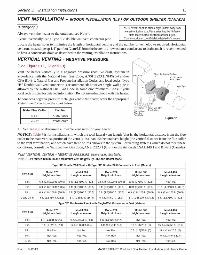
(Category I)Always vent the heater to the outdoors, see Note*.• Vent it vertically using Type “B” double wall vent connector pipe.Locate the heater so as to minimize the length of horizontal venting and the number of vent elbows required. Horizontalvent runs must slope up 1/4" per foot (2cm/M) from the heater to allow exhaust condensate to drain and it is recommendedto have a condensate drain as described in the venting installation instructions.
VERTICAL VENTING - NEGATIVE PRESSURE(See Figures 11, 12 and 13)Vent the heater vertically in a negative pressure (positive draft) system inaccordance with the National Fuel Gas Code, ANSI Z223.1/NFPA 54 and/orCSA B149.1, Natural Gas and Propane Installation Codes, and local codes. Type“B” Double-wall vent connector is recommended; however single-wall pipe isallowed by the National Fuel Gas Code in some circumstances. Consult yourlocal code official for detailed information. Do not use a draft hood with this heater.To connect a negative pressure metal gas vent to the heater, order the appropriateMetal Flue Collar from the chart below:
Section 3. Installation Instructions
CombustionChamberFlue Collar
4" x 8" Metal Flue Collar
Vent BodVV yyClean the Interior Surface
Vent Pipe
Clean and RTV This Surface
Figure 11.
1. See Table 7, to determine allowable vent sizes for your heater.NOTICE: Table 7 is for installations in which the total lateral vent length (that is, the horizontal distance from the fluecollar to the main vertical portion of the vent) is less than 1/2 the total vent height (the vertical distance from the flue collarto the vent termination) and which have three or less elbows in the system. For venting systems which do not meet theseconditions, consult the National Fuel Gas Code, ANSI Z223.1 (U.S.), or the standards CSA B149.1 and B149.2 (Canada).
Read “VERTICAL VENTING – NEGATIVE PRESSURE” before using this table.Table 7. – Permitted Minimum and Maximum Vent Heights By Size and Heater Model
NOTE *: Vent must be at least eight (8) feet away fromnearest vertical surface. Vents extending five (5) feet or
more above the roof must be braced or guyed.Consult your local code officials for detailed information.
ralloCeulFlateM .oNtraP
"6x4 6700-70777
"8x4 7700-70777
)sreteM(teeFnirotcennoCllaW-elbuoD"B"epyThtiwtneVllaW-elbuoD"B"epyT
eziStneV 571ledoM.xam/.nimthgieH
002ledoM.xam/.nimthgieH
052ledoM.xam/.nimthgieH
003ledoM.xam/.nimthgieH
004ledoM.xam/.nimthgieH
.ni6 )5.03(.tf001/)8.1(.tf6 )5.03(.tf001/)8.1(.tf6 )5.03(.tf001/)5.5(.tf81 )5.03(.tf001/)9(.tf03 .ceRtoN
.ni7 )5.03(.tf001/)8.1(.tf6 )5.03(.tf001/)8.1(.tf6 )5.03(.tf001/)4.2(.tf8 )5.03(.tf001/)3(.tf01 )5.03(.tf001/)6.4(.tf51
.ni8 )5.03(.tf001/)8.1(.tf6 )5.03(.tf001/)8.1(.tf6 )5.03(.tf001/)8.1(.tf6 )5.03(.tf001/)8.1(.tf6 )5.03(.tf001/)4.2(.tf8
.ni01dna9 )3.51(.tf05/)8.1(.tf6 )3.51(.tf05/)8.1(.tf6 )3.51(.tf05/)8.1(.tf6 )5.03(.tf001/)8.1(.tf6 )5.03(.tf001/)8.1(.tf6
)sreteM(teeFnirotcennoCllaW-elgniShtiwtneVllaW-elbuoD"B"epyT
eziStneV 571ledoM.xam/.nimthgieH
002ledoM.xam/.nimthgieH
052ledoM.xam/.nimthgieH
003ledoM.xam/.nimthgieH
004ledoM.xam/.nimthgieH
.ni6 )6.4(.tf51/)8.1(.tf6 )6.4(.tf51/)8.1(.tf6 )6.4(.tf51/)8.1(.tf6 .ceRtoN .ceRtoN
.ni7 )4.2(.tf8/)8.1(.tf6 )4.2(.tf8/)8.1(.tf6 )4.2(.tf8/)8.1(.tf6 )6(.tf02/)3(.tf01 )3.51(.tf05/)6.4(.tf51
.ni8 .ceRtoN .ceRtoN .ceRtoN )6(.tf02/)8.1(.tf6 )6(.tf02/)4.2(.tf8
.ni9 .ceRtoN .ceRtoN .ceRtoN .ceRtoN )8.1(.tf6/)8.1(.tf6
.ni01 .ceRtoN .ceRtoN .ceRtoN .ceRtoN .ceRtoN
MASTERTEMP® Pool and Spa Heater Installation and User’s Guide Rev. L 8-12-14
22
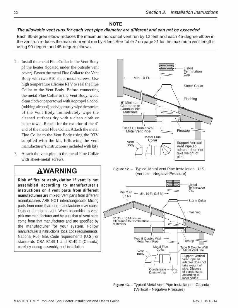
2. Install the metal Flue Collar in the Vent Bodyof the heater (located under the outside ventcover). Fasten the metal Flue Collar to the VentBody with two #10 sheet metal screws. Usehigh temperature silicone RTV to seal the FlueCollar to the Vent Body. Before connectingthe metal Flue Collar to the Vent Body, wet aclean cloth or paper towel with isopropyl alcohol(rubbing alcohol) and vigorously wipe the socketof the Vent Body. Immediately wipe thecleaned surfaces dry with a clean cloth orpaper towel. Repeat for the exterior of the 4"end of the metal Flue Collar. Attach the metalFlue Collar to the Vent Body using the RTVsupplied with the kit, following the ventmanufacturer’s instructions (included with kit).
3. Attach the vent pipe to the metal Flue Collarwith sheet-metal screws.
WARNINGRisk of fire or asphyxiation if vent is notassembled according to manufacturer ’sinstructions or if vent parts from differentmanufacturers are mixed. Vent parts from differentmanufacturers ARE NOT interchangeable. Mixingparts from more than one manufacturer may causeleaks or damage to vent. When assembling a vent,pick one manufacturer and be sure that all vent partscome from that manufacturer and are specified bythe manufacturer for your system. Followmanufacturer’s instructions, local code requirements,National Fuel Gas Code requirements (U.S.) orstandards CSA B149.1 and B149.2 (Canada)carefully during assembly and installation.
Section 3. Installation Instructions
6" (15 cm) MinimumClearance to CombustibleMaterials
ListedTermination Cap
Storm Collar
Flashing
Firestop
VentBody
Metal FlueCollar
Type B Double WallMetal Vent Pipe
Min. 10 Ft. (3.3 M)
Support Vertical Vent Pipe so adapter does not take weight of pipe. Dispose of condensateaccording to local codes.
Type B Double WallMetal Vent Tee
CondensateDrain w/trap
Min. 2 Ft. (.7 M)
6" MinimumClearance toCombustible
Materials
ListedTermination Cap
Storm Collar
Flashing
Firestop
VentBody
Metal FlueCollar
Class B Double WallMetal Vent Pipe
Min. 10 Ft.
Support Vertical Vent Pipe so adapter does not take weight of pipe.
Figure 13. – Typical Metal Vent Pipe Installation - Canada(Vertical – Negative Pressure)
Figure 12. – Typical Metal Vent Pipe Installation - U.S.(Vertical – Negative Pressure)
NOTEThe allowable vent runs for each vent pipe diameter are different and can not be exceeded.Each 90-degree elbow reduces the maximum horizontal vent run by 12 feet and each 45-degree elbow inthe vent run reduces the maximum vent run by 6 feet. See Table 7 on page 21 for the maximum vent lengthsusing 90-degree and 45-degree elbows.
Rev. L 8-12-13 MASTERTEMP® Pool and Spa Heater Installation and User’s Guide
23Section 3. Installation Instructions
4. Install vent pipe so that it can expand and contract freely as the temperature changes. Support the vent pipe accordingto applicable codes and the vent manufacturer’s instructions. Pipe support must allow the vent pipe free movementout and back, from side to side, or up and down as necessary, without putting a strain on the heater or vent body. Slopehorizontal pipe runs up from the heater at least 1/4" per foot (2cm per meter). Install Listed condensate drains at lowpoints where condensate might collect. Plumb condensate drains to a drain through hard piping or high temperaturetubing such as silicone rubber or EPDM rubber – do not use vinyl or other low temperature tubing. Follow drainmanufacturer’s installation instructions.
5. Use Listed fire stop for floor and ceiling penetrations. Use Listed thimble for wall penetrations. Use a Listed roofflashing, roof jack, or roof thimble for all roof penetrations. Do not fill the space around the vent (that is, the clear airspace in the thimble or fire stop) with insulation. The roof opening must be located so that the vent is vertical.
6. Do not run the heater vent into a common vent with any other appliance.
WARNINGFire Hazard. Do not vent the heater directly into a masonry chimney. Installation into a masonry chimney must use achimney liner and must meet the National Fuel Gas Code, ANSI Z223.1/NFPA 54 and/or CSA B149.1, Natural Gas and PropaneInstallation Codes requirements and all local code requirements.
WARNINGRisk of fire, carbon monoxide poisoning, or asphyxiation. It is recommended to use a CO Monitor and Fire Alarm in roomsthat contain gas fired appliances.
MASTERTEMP® Pool and Spa Heater Installation and User’s Guide Rev. L 8-12-14
24
HORIZONTAL OR VERTICAL VENTING - POSITIVE PRESSURE (See Figures 14, 15, and 16)
(Category III)Vent the heater either horizontally or vertically using an optional vent adapter of the 4-inch special gas approved Category IIIvent pipes. Install the vent pipe in accordance with local codes and the provisions of the National Fuel Gas Code, ANSIZ223.1 (U.S.), or the standards CSA B149.1, Natural Gas and Propane Installation Codes (Canada), and the ventmanufacturer’s instructions. Do not use a draft hood with this heater. Install the vent according to the vent manufacturer’sdetailed instructions. Note: Maintain clearance between the vent pipe and combustible surfaces according to the ventmanufacturer’s instructions and code requirements. Do not place any insulating materials around the vent or inside therequired clear air space surrounding the vent. See Table 11 for maximum permissible vent lengths.
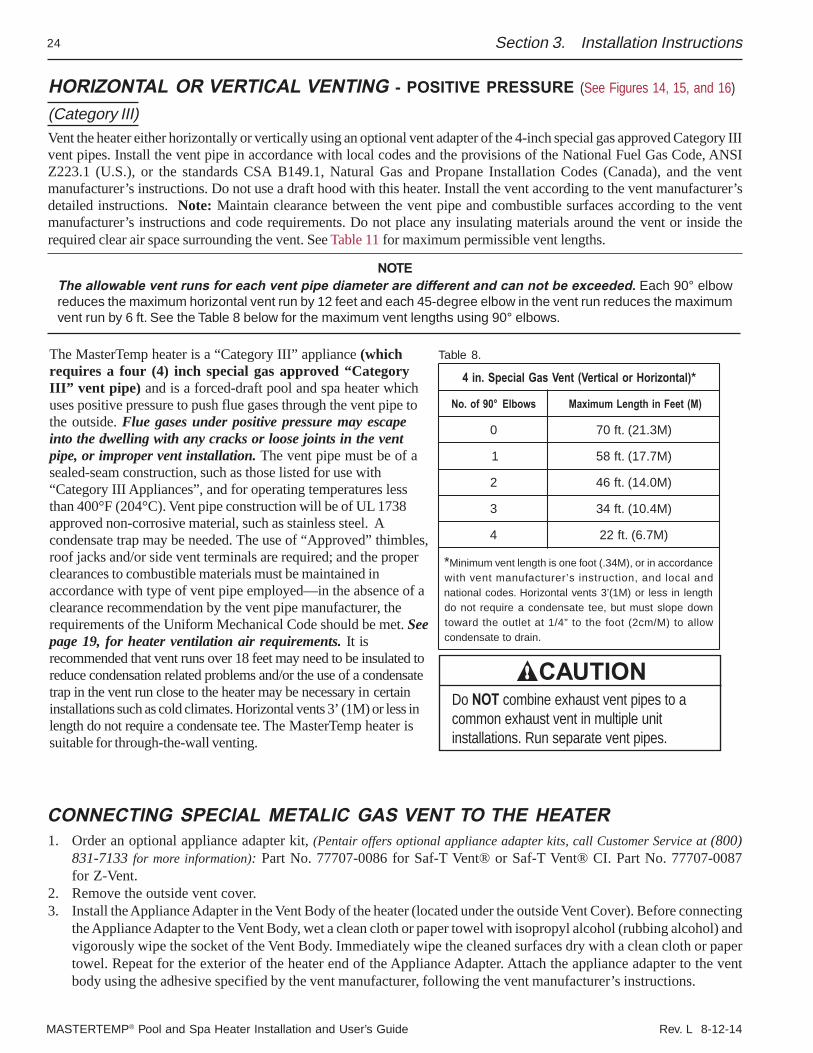
NOTEThe allowable vent runs for each vent pipe diameter are different and can not be exceeded. Each 90° elbowreduces the maximum horizontal vent run by 12 feet and each 45-degree elbow in the vent run reduces the maximumvent run by 6 ft. See the Table 8 below for the maximum vent lengths using 90° elbows.
1. Order an optional appliance adapter kit, (Pentair offers optional appliance adapter kits, call Customer Service at (800)831-7133 for more information): Part No. 77707-0086 for Saf-T Vent® or Saf-T Vent® CI. Part No. 77707-0087for Z-Vent.
2. Remove the outside vent cover.3. Install the Appliance Adapter in the Vent Body of the heater (located under the outside Vent Cover). Before connecting
the Appliance Adapter to the Vent Body, wet a clean cloth or paper towel with isopropyl alcohol (rubbing alcohol) andvigorously wipe the socket of the Vent Body. Immediately wipe the cleaned surfaces dry with a clean cloth or papertowel. Repeat for the exterior of the heater end of the Appliance Adapter. Attach the appliance adapter to the ventbody using the adhesive specified by the vent manufacturer, following the vent manufacturer’s instructions.
Section 3. Installation Instructions
Table 8.
)latnoziroHrolacitreV(tneVsaGlaicepS.ni4 *
swoblE°09fo.oN )M(teeFnihtgneLmumixaM
0 )M3.12(.tf07
1 )M7.71(.tf85
2 )M0.41(.tf64
3 )M4.01(.tf43
4 )M7.6(.tf22
* ecnadroccaniro,)M43.(toofenosihtgneltnevmuminiMdnalacoldna,noitcurtsnis’rerutcafunamtnevhtiwhtgnelnisselro)M1(’3stnevlatnoziroH.sedoclanoitannwodepolstsumtub,eetetasnednocaeriuqertonodwollaot)M/mc2(toofehtot”4/1tateltuoehtdrawot
.niardotetasnednoc
CAUTIONDo NOT combine exhaust vent pipes to acommon exhaust vent in multiple unitinstallations. Run separate vent pipes.
CONNECTING SPECIAL METALIC GAS VENT TO THE HEATER
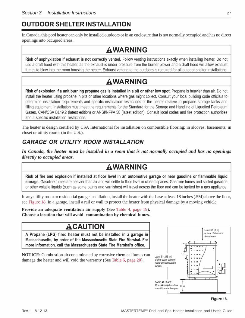
The MasterTemp heater is a “Category III” appliance (whichrequires a four (4) inch special gas approved “CategoryIII” vent pipe) and is a forced-draft pool and spa heater whichuses positive pressure to push flue gases through the vent pipe tothe outside. Flue gases under positive pressure may escapeinto the dwelling with any cracks or loose joints in the ventpipe, or improper vent installation. The vent pipe must be of asealed-seam construction, such as those listed for use with“Category III Appliances”, and for operating temperatures lessthan 400°F (204°C). Vent pipe construction will be of UL 1738approved non-corrosive material, such as stainless steel. Acondensate trap may be needed. The use of “Approved” thimbles,roof jacks and/or side vent terminals are required; and the properclearances to combustible materials must be maintained inaccordance with type of vent pipe employed—in the absence of aclearance recommendation by the vent pipe manufacturer, therequirements of the Uniform Mechanical Code should be met. Seepage 19, for heater ventilation air requirements. It isrecommended that vent runs over 18 feet may need to be insulated toreduce condensation related problems and/or the use of a condensatetrap in the vent run close to the heater may be necessary in certaininstallations such as cold climates. Horizontal vents 3’ (1M) or less inlength do not require a condensate tee. The MasterTemp heater issuitable for through-the-wall venting.
Rev. L 8-12-13 MASTERTEMP® Pool and Spa Heater Installation and User’s Guide
25Section 3. Installation Instructions
WARNINGRisk of carbon monoxide poisoning if adapter is improperly attached. Mechanical connections (such as screws) cancause cracking and leaks in the adapter. Do NOT drill holes or use screws to connect the appliance adapter to the heater ventbody. Attach with manufacturer’s specified adhesive.
WARNINGRisk of fire or asphyxiation if vent is not assembled according to manufacturer’s instructions or if vent parts fromdifferent manufacturers are mixed. Vent parts from different manufacturers ARE NOT interchangeable. Mixing parts frommore than one manufacturer may cause leaks or damage to vent. When installing a vent, pick one manufacturer and be surethat all vent parts come from that manufacturer and are specified by the manufacturer for your system. Follow manufacturer’sinstructions and local and National Fuel Gas Code (U.S.) or CSA B149.1, Natural Gas and Propane Installation Codes(Canada) requirements carefully during assembly and installation.
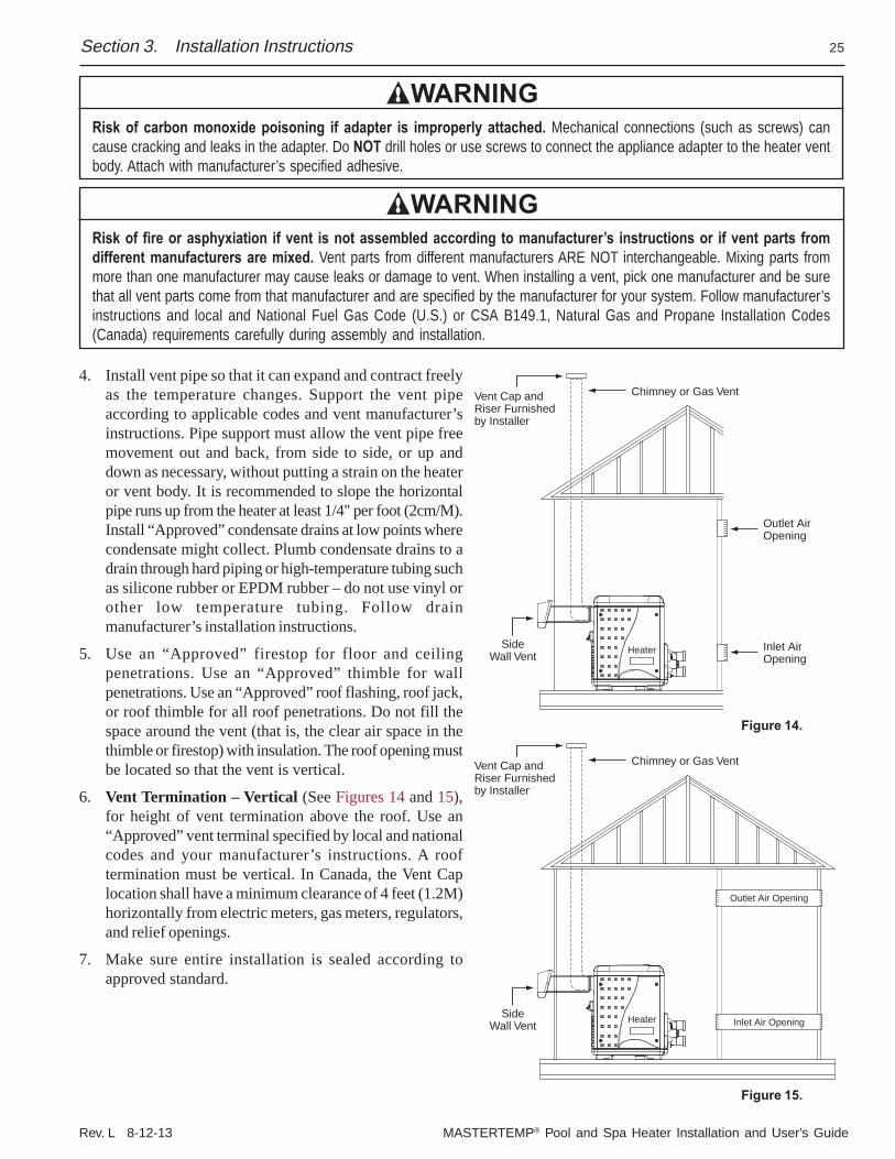
4. Install vent pipe so that it can expand and contract freelyas the temperature changes. Support the vent pipeaccording to applicable codes and vent manufacturer’sinstructions. Pipe support must allow the vent pipe freemovement out and back, from side to side, or up anddown as necessary, without putting a strain on the heateror vent body. It is recommended to slope the horizontalpipe runs up from the heater at least 1/4" per foot (2cm/M).Install “Approved” condensate drains at low points wherecondensate might collect. Plumb condensate drains to adrain through hard piping or high-temperature tubing suchas silicone rubber or EPDM rubber – do not use vinyl orother low temperature tubing. Follow drainmanufacturer’s installation instructions.
5. Use an “Approved” firestop for floor and ceilingpenetrations. Use an “Approved” thimble for wallpenetrations. Use an “Approved” roof flashing, roof jack,or roof thimble for all roof penetrations. Do not fill thespace around the vent (that is, the clear air space in thethimble or firestop) with insulation. The roof opening mustbe located so that the vent is vertical.
6. Vent Termination – Vertical (See Figures 14 and 15),for height of vent termination above the roof. Use an“Approved” vent terminal specified by local and nationalcodes and your manufacturer’s instructions. A rooftermination must be vertical. In Canada, the Vent Caplocation shall have a minimum clearance of 4 feet (1.2M)horizontally from electric meters, gas meters, regulators,and relief openings.
7. Make sure entire installation is sealed according toapproved standard.
Outlet AirOpening
Inlet AirOpening
Chimney or Gas VentVent Cap and Riser Furnishedby Installer
SideWall Vent Heater
Chimney or Gas VentVent Cap and Riser Furnishedby Installer
SideWall Vent Heater
Outlet Air Opening
Inlet Air Opening
Figure 14.
Figure 15.
MASTERTEMP® Pool and Spa Heater Installation and User’s Guide Rev. L 8-12-14
26
1' Min.
4' Min.4' Min.
4' Min.
4' Min.
3' Minimum clearance ifhorizontal distance toexhaust opening is lessthan 10 feet.
Forced AirInlet
VentTermination
1' Minimumabove snow orfinished grade(whichever ishigher)
At least 7' above grade adjacentto publicwalkways
VentTermination Vent
Termination
Gas Meter
Max. 12"Min. 3"
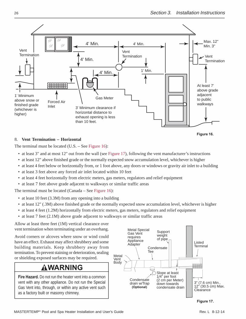
Figure 16.8. Vent Termination – HorizontalThe terminal must be located (U.S. – See Figure 16):
• at least 3" and at most 12" out from the wall (see Figure 17), following the vent manufacturer’s instructions• at least 12" above finished grade or the normally expected snow accumulation level, whichever is higher• at least 4 feet below or horizontally from, or 1 foot above, any doors or windows or gravity air inlet to a building• at least 3 feet above any forced air inlet located within 10 feet• at least 4 feet horizontally from electric meters, gas meters, regulators and relief equipment• at least 7 feet above grade adjacent to walkways or similar traffic areas
The terminal must be located (Canada – See Figure 16):
• at least 10 feet (3.3M) from any opening into a building• at least 12" (.3M) above finished grade or the normally expected snow accumulation level, whichever is higher• at least 4 feet (1.2M) horizontally from electric meters, gas meters, regulators and relief equipment• at least 7 feet (2.1M) above grade adjacent to walkways or similar traffic areas
Allow at least three feet (1M) vertical clearance overvent termination when terminating under an overhang.
Avoid corners or alcoves where snow or wind couldhave an effect. Exhaust may affect shrubbery and somebuilding materials. Keep shrubbery away fromtermination. To prevent staining or deterioration, sealingor shielding exposed surfaces may be required.
WARNINGFire Hazard. Do not run the heater vent into a commonvent with any other appliance. Do not run the SpecialGas Vent into, through, or within any active vent suchas a factory built or masonry chimney.
3" (7.6 cm) Min.,12" (30.5 cm) Max.Clearance
Condensatedrain w/Trap
CondensateTee
Support weightof pipe
ListedTerminal
Metal Special Gas VentrequiresApplianceAdapter
MetalVentBody
Slope at least 1/4" per foot(2 cm per Meter) down towards condensate drain(Optional)
Figure 17.
Section 3. Installation Instructions
Rev. L 8-12-13 MASTERTEMP® Pool and Spa Heater Installation and User’s Guide
27
Leave 6 in. (15 cm)of clear space between heater and combustiblesurface.
Leave 3 ft. (1 m)or more of clearanceabove heater
RAISE AT LEAST 18 in. (46 cm) above floorto avoid flammable vapors
18 in.
In Canada, this pool heater can only be installed outdoors or in an enclosure that is not normally occupied and has no directopenings into occupied areas.
WARNINGRisk of asphyxiation if exhaust is not correctly vented. Follow venting instructions exactly when installing heater. Do notuse a draft hood with this heater, as the exhaust is under pressure from the burner blower and a draft hood will allow exhaustfumes to blow into the room housing the heater. Exhaust venting to the outdoors is required for all outdoor shelter installations.
WARNINGRisk of explosion if a unit burning propane gas is installed in a pit or other low spot. Propane is heavier than air. Do notinstall the heater using propane in pits or other locations where gas might collect. Consult your local building code officials todetermine installation requirements and specific installation restrictions of the heater relative to propane storage tanks andfilling equipment. Installation must meet the requirements for the Standard for the Storage and Handling of Liquefied PetroleumGases, CAN/CSA B149.2 (latest edition) or ANSI/NFPA 58 (latest edition). Consult local codes and fire protection authoritiesabout specific installation restrictions.
The heater is design certified by CSA International for installation on combustible flooring; in alcoves; basements; incloset or utility rooms (in the U.S.).
GARAGE OR UTILITY ROOM INSTALLATIONIn Canada, the heater must be installed in a room that is not normally occupied and has no openingsdirectly to occupied areas.
WARNINGRisk of fire and explosion if installed at floor level in an automotive garage or near gasoline or flammable liquidstorage. Gasoline fumes are heavier than air and will settle to floor level in closed spaces. Gasoline fumes and spilled gasolineor other volatile liquids (such as some paints and varnishes) will travel across the floor and can be ignited by a gas appliance.
In any utility room or residential garage installation, install the heater with the base at least 18 inches (.5M) above the floor,see Figure 18. In a garage, install a rail or wall to protect the heater from physical damage by a moving vehicle.
Provide an adequate ventilation air supply (See Table 4, page 19).Choose a location that will avoid contamination by chemical fumes.
CAUTIONA Propane (LPG) fired heater must not be installed in a garage inMassachusetts, by order of the Massachusetts State Fire Marshal. Formore information, call the Massachusetts State Fire Marshal’s office.
NOTICE: Combustion air contaminated by corrosive chemical fumes candamage the heater and will void the warranty (See Table 6, page 20).
Section 3. Installation Instructions
OUTDOOR SHELTER INSTALLATION
Figure 18.
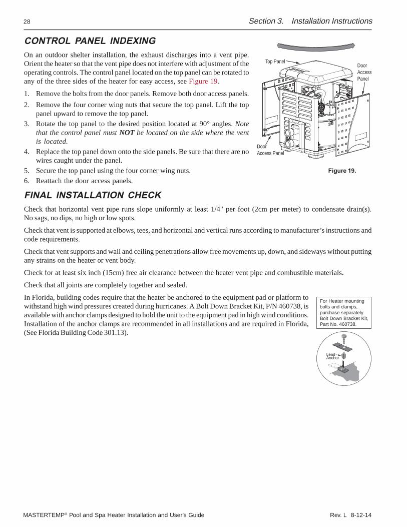
MASTERTEMP® Pool and Spa Heater Installation and User’s Guide Rev. L 8-12-14
28 Section 3. Installation Instructions
CONTROL PANEL INDEXINGOn an outdoor shelter installation, the exhaust discharges into a vent pipe.Orient the heater so that the vent pipe does not interfere with adjustment of theoperating controls. The control panel located on the top panel can be rotated toany of the three sides of the heater for easy access, see Figure 19.
1. Remove the bolts from the door panels. Remove both door access panels.2. Remove the four corner wing nuts that secure the top panel. Lift the top
panel upward to remove the top panel.3. Rotate the top panel to the desired position located at 90° angles. Note
that the control panel must NOT be located on the side where the ventis located.
4. Replace the top panel down onto the side panels. Be sure that there are nowires caught under the panel.
5. Secure the top panel using the four corner wing nuts.6. Reattach the door access panels.
FINAL INSTALLATION CHECKCheck that horizontal vent pipe runs slope uniformly at least 1/4" per foot (2cm per meter) to condensate drain(s).No sags, no dips, no high or low spots.
Check that vent is supported at elbows, tees, and horizontal and vertical runs according to manufacturer’s instructions andcode requirements.
Check that vent supports and wall and ceiling penetrations allow free movements up, down, and sideways without puttingany strains on the heater or vent body.
Check for at least six inch (15cm) free air clearance between the heater vent pipe and combustible materials.
Check that all joints are completely together and sealed.
In Florida, building codes require that the heater be anchored to the equipment pad or platform towithstand high wind pressures created during hurricanes. A Bolt Down Bracket Kit, P/N 460738, isavailable with anchor clamps designed to hold the unit to the equipment pad in high wind conditions.Installation of the anchor clamps are recommended in all installations and are required in Florida,(See Florida Building Code 301.13).
DoorAccessPanel
Top Panel
DoorAccess Panel
Figure 19.
LeadAnchor
For Heater mountingbolts and clamps, purchase separatelyBolt Down Bracket Kit, Part No. 460738.
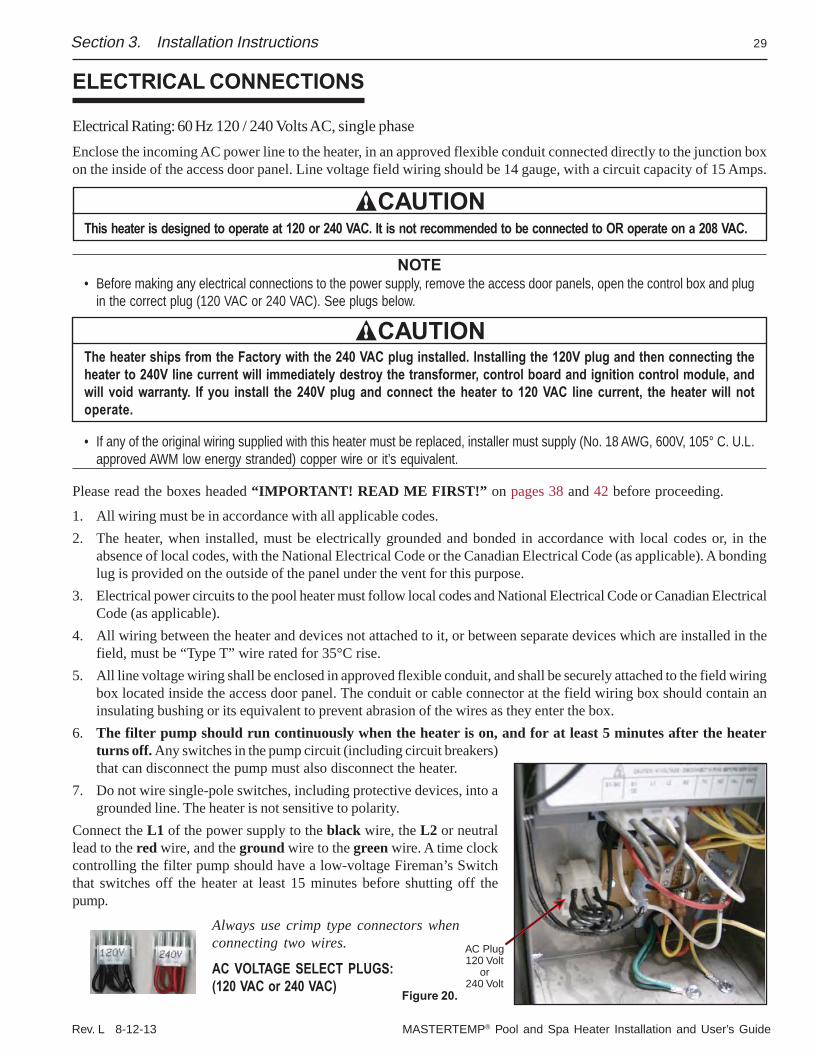
Rev. L 8-12-13 MASTERTEMP® Pool and Spa Heater Installation and User’s Guide
29
ELECTRICAL CONNECTIONS
Electrical Rating: 60 Hz 120 / 240 Volts AC, single phaseEnclose the incoming AC power line to the heater, in an approved flexible conduit connected directly to the junction boxon the inside of the access door panel. Line voltage field wiring should be 14 gauge, with a circuit capacity of 15 Amps.
CAUTIONThis heater is designed to operate at 120 or 240 VAC. It is not recommended to be connected to OR operate on a 208 VAC.
NOTE• Before making any electrical connections to the power supply, remove the access door panels, open the control box and plug
in the correct plug (120 VAC or 240 VAC). See plugs below.
CAUTIONThe heater ships from the Factory with the 240 VAC plug installed. Installing the 120V plug and then connecting theheater to 240V line current will immediately destroy the transformer, control board and ignition control module, andwill void warranty. If you install the 240V plug and connect the heater to 120 VAC line current, the heater will notoperate.
• If any of the original wiring supplied with this heater must be replaced, installer must supply (No. 18 AWG, 600V, 105° C. U.L.approved AWM low energy stranded) copper wire or it’s equivalent.
Please read the boxes headed “IMPORTANT! READ ME FIRST!” on pages 38 and 42 before proceeding.
1. All wiring must be in accordance with all applicable codes.2. The heater, when installed, must be electrically grounded and bonded in accordance with local codes or, in the
absence of local codes, with the National Electrical Code or the Canadian Electrical Code (as applicable). A bondinglug is provided on the outside of the panel under the vent for this purpose.
3. Electrical power circuits to the pool heater must follow local codes and National Electrical Code or Canadian ElectricalCode (as applicable).
4. All wiring between the heater and devices not attached to it, or between separate devices which are installed in thefield, must be “Type T” wire rated for 35°C rise.
5. All line voltage wiring shall be enclosed in approved flexible conduit, and shall be securely attached to the field wiringbox located inside the access door panel. The conduit or cable connector at the field wiring box should contain aninsulating bushing or its equivalent to prevent abrasion of the wires as they enter the box.
6. The filter pump should run continuously when the heater is on, and for at least 5 minutes after the heaterturns off. Any switches in the pump circuit (including circuit breakers)that can disconnect the pump must also disconnect the heater.
7. Do not wire single-pole switches, including protective devices, into agrounded line. The heater is not sensitive to polarity.
Connect the L1 of the power supply to the black wire, the L2 or neutrallead to the red wire, and the ground wire to the green wire. A time clockcontrolling the filter pump should have a low-voltage Fireman’s Switchthat switches off the heater at least 15 minutes before shutting off thepump.
Always use crimp type connectors whenconnecting two wires.
Section 3. Installation Instructions
Figure 20.
AC Plug120 Volt
or240 Volt
AC VOLTAGE SELECT PLUGS:(120 VAC or 240 VAC)
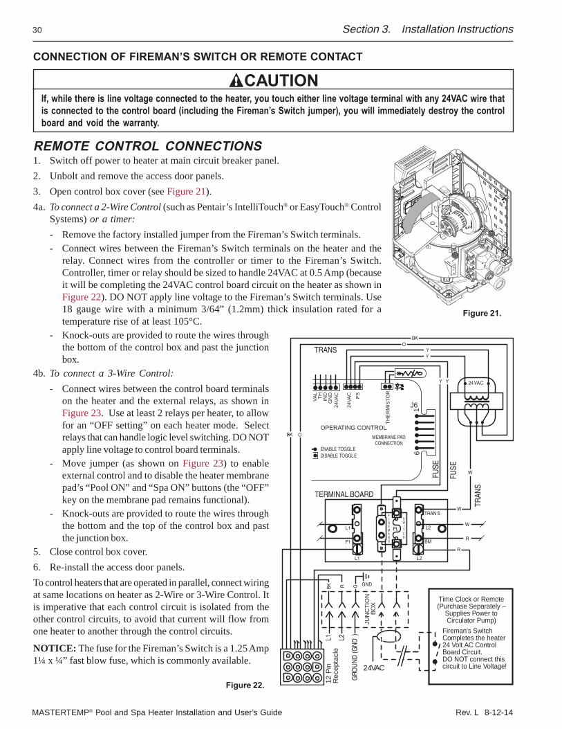
MASTERTEMP® Pool and Spa Heater Installation and User’s Guide Rev. L 8-12-14
30
Figure 21.
Section 3. Installation Instructions
CONNECTION OF FIREMAN’S SWITCH OR REMOTE CONTACT
CAUTIONIf, while there is line voltage connected to the heater, you touch either line voltage terminal with any 24VAC wire thatis connected to the control board (including the Fireman’s Switch jumper), you will immediately destroy the controlboard and void the warranty.
REMOTE CONTROL CONNECTIONS1. Switch off power to heater at main circuit breaker panel.2. Unbolt and remove the access door panels.3. Open control box cover (see Figure 21).4a. To connect a 2-Wire Control (such as Pentair’s IntelliTouch® or EasyTouch® Control
Systems) or a timer:- Remove the factory installed jumper from the Fireman’s Switch terminals.- Connect wires between the Fireman’s Switch terminals on the heater and the
relay. Connect wires from the controller or timer to the Fireman’s Switch.Controller, timer or relay should be sized to handle 24VAC at 0.5 Amp (becauseit will be completing the 24VAC control board circuit on the heater as shown inFigure 22). DO NOT apply line voltage to the Fireman’s Switch terminals. Use18 gauge wire with a minimum 3/64” (1.2mm) thick insulation rated for atemperature rise of at least 105°C.
- Knock-outs are provided to route the wires throughthe bottom of the control box and past the junctionbox.
4b. To connect a 3-Wire Control:- Connect wires between the control board terminals
on the heater and the external relays, as shown inFigure 23. Use at least 2 relays per heater, to allowfor an “OFF setting” on each heater mode. Selectrelays that can handle logic level switching. DO NOTapply line voltage to control board terminals.
- Move jumper (as shown on Figure 23) to enableexternal control and to disable the heater membranepad’s “Pool ON” and “Spa ON” buttons (the “OFF”key on the membrane pad remains functional).
- Knock-outs are provided to route the wires throughthe bottom and the top of the control box and pastthe junction box.
5. Close control box cover.6. Re-install the access door panels.To control heaters that are operated in parallel, connect wiringat same locations on heater as 2-Wire or 3-Wire Control. Itis imperative that each control circuit is isolated from theother control circuits, to avoid that current will flow fromone heater to another through the control circuits.
NOTICE: The fuse for the Fireman’s Switch is a 1.25 Amp1¼ x ¼” fast blow fuse, which is commonly available.
GND
L1
GRO
UN
D (G
ND
)
L2
JUN
CTI
ON
BO
X
L1 L2
BM
FL
F1
L1
TRAN SFIREMANS
SWITCH
Fireman's SwitchCompletes the heater24 Volt AC Control Board Circuit.DO NOT connect thiscircuit to Line Voltage!
Y Y
R
W
GYY
TERMINAL BOARD
TRANS
TRAN
S
FUSE
FUSE
L2
Time Clock or Remote(Purchase Separately –
Supplies Power toCirculator Pump)
24VAC
24VAC
BK
O
O
BK
W
R
BK R
W
12 P
inR
ecep
tacl
e
VAL
TH IND
GN
D24
VAC
24VA
C FS
THE
RM
ISTO
R
OPERATING CONTROL
DISABLE TOGGLEENABLE TOGGLE
MEMBRANE PADCONNECTION
9
1J6
Figure 22.
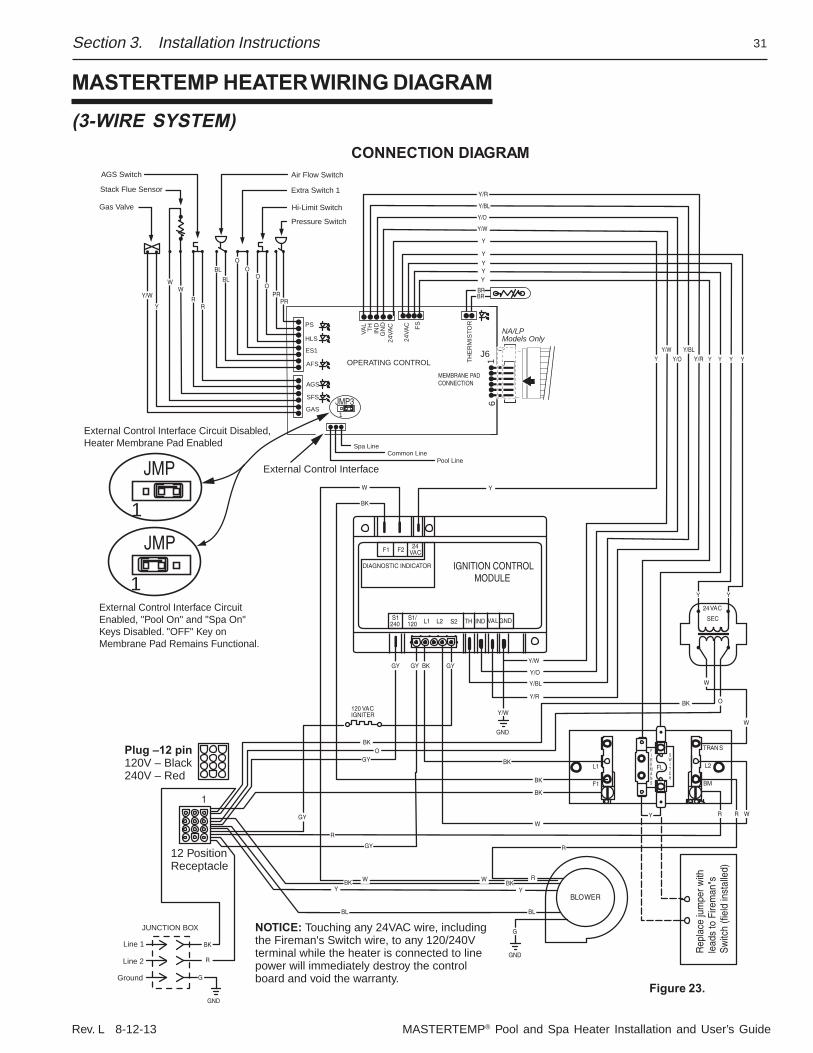
Rev. L 8-12-13 MASTERTEMP® Pool and Spa Heater Installation and User’s Guide
31
MASTERTEMP HEATER WIRING DIAGRAM
(3-WIRE SYSTEM)
Section 3. Installation Instructions
Plug –12 pin120V – Black240V – Red
JMP
1
JMP
1
External Control Interface Circuit Disabled, Heater Membrane Pad Enabled
External Control Interface Circuit Enabled, "Pool On" and "Spa On" Keys Disabled. "OFF" Key on Membrane Pad Remains Functional.
JMP3
CONNECTION DIAGRAMAGS Switch
Stack Flue Sensor
Gas Valve
Air Flow Switch
Extra Switch 1
Hi-Limit Switch
Pressure Switch
VAL
TH IND
GN
D24
VAC
24VA
C FS
THE
RM
ISTO
R
OPERATING CONTROL
1
PS
HLS
ES1
AFS
AGS
SFS
GAS
MEMBRANE PADCONNECTION
Spa LineCommon Line
Pool Line
IGNITION CONTROLMODULE
DIAGNOSTIC INDICATOR
F1 F2 24VAC
S1240
S1/120 L1
L1 L2
BM
FL
F1
L2 S2 TH IND VALGND
GND
GND
BLOWER
Line 2
120 VACIGNITER
TRAN S
Line 1
Ground
JUNCTION BOX
FIREMANS
SWITCH
Rep
lace
jum
per w
ithle
ads
to F
irem
an"s
Sw
itch
(fiel
d in
stal
led)
24VAC
SEC
Y/W
Y/W
Y/R
Y/O
Y/BL
O
W
W
BK
BKO
GY
GY
BK
BK
R
YBK
W
BL
YBK W
BL
GY
GY
GY
GY
BK
BK
W
RR W
G
Y
R
R
Y
YY
W
BK
Y/W
WW
RR
BL
BL
OO
O
OPR
PR
Y/R
Y/BL
Y/O
Y/W
Y
Y
YYY
YY Y Y Y
BRBR
External Control Interface
Y
NOTICE: Touching any 24VAC wire, includingthe Fireman's Switch wire, to any 120/240Vterminal while the heater is connected to line power will immediately destroy the control board and void the warranty.
BK
RGND
G
12 PositionReceptacle
1
Y/R
Y/BL
Y/O
Y/W
NA/LPModels Only
61
J6
Figure 23.
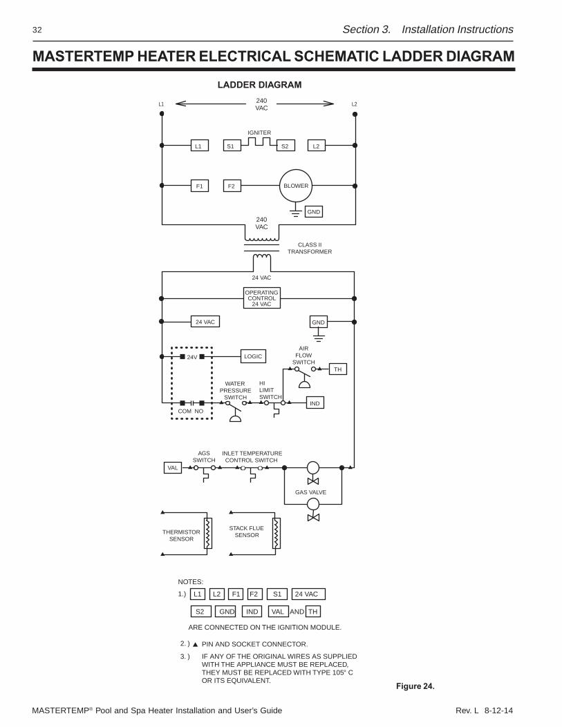
MASTERTEMP® Pool and Spa Heater Installation and User’s Guide Rev. L 8-12-14
32 Section 3. Installation Instructions
MASTERTEMP HEATER ELECTRICAL SCHEMATIC LADDER DIAGRAM
Figure 24.
L1 L2240VAC
240VAC
IGNITER
L1 S1 S2 L2
F1 F2 BLOWER
GND
GND
CLASS IITRANSFORMER
24 VAC
24 VAC
24V
OPERATINGCONTROL
24 VAC
LOGIC
TH
IND
AIRFLOW
SWITCH
HILIMITSWITCH
WATERPRESSURE
SWITCH
COM NO
AGSSWITCH
VAL
GAS VALVE
THERMISTORSENSOR
STACK FLUESENSOR
NOTES:
1.)
AND TH
L1 L2 F1 F2 S1 24 VAC
S2 GND IND VAL
ARE CONNECTED ON THE IGNITION MODULE.
2. )
3. )
PIN AND SOCKET CONNECTOR.
IF ANY OF THE ORIGINAL WIRES AS SUPPLIED WITH THE APPLIANCE MUST BE REPLACED, THEY MUST BE REPLACED WITH TYPE 105° COR ITS EQUIVALENT.
LADDER DIAGRAM
INLET TEMPERATURECONTROL SWITCH
Rev. L 8-12-13 MASTERTEMP® Pool and Spa Heater Installation and User’s Guide
33
BASIC SYSTEM OPERATION
Start pump, make sure the pump is running and is primed, to close the water pressure switch and supplypower to heater. Be sure the pool and/or spa is properly filled with water. Follow the Lighting/Operating instructionsbelow.
Section 4. Operation Instructions
Operation Instructions
FOR YOUR SAFETY: READ BEFORE LIGHTING
START-UP AND OPERATIONSTART-UP AND SHUTDOWN INSTRUCTIONS ARE ON THE LABEL ATTACHED TO THE COVER OF THE APPLIANCECONTROL BOX.
MASTERTEMP HEATER HSI ELECTRONIC IGNITION LIGHTING/OPERATION
If you do not follow these instructions exactly, a fire or explosion may result causing property damage, personalinjury or loss of life.Do not attempt to light the heater if you suspect a gas leak. Lighting the heater can result in a fire or explosionwhich can cause personal injury, death, and property damage.
WARNING
BEFORE START-UPA. This appliance does not have a pilot. It is equipped with
an ignition device which automatically lights the burners.Do not try to light the burners by hand.
B. BEFORE OPERATING, smell all around theappliance area for gas. Be sure to smell next to the floorbecause some gas is heavier than air and will settle onthe floor.
WHAT TO DO IF YOU SMELL GAS– Do not try to light any appliance.– Do not touch any electrical switch; do not use any phone
in your building.– Immediately call your gas supplier from a neighbor's
phone. Follow the gas supplier's instructions.– If you cannot reach your gas supplier, call the Fire
Department.C. Use only your hand to turn the gas control on or off.
Never use tools. If you cannot change the ON/OFFsetting by hand, don't try to repair it, call a qualifiedservice technician. Forced or attempted repair may resultin a fire or explosion.
D. Do not use this heater if any part has been under water.Immediately call a qualified service technician to inspectthe heater and to replace any part of the control systemand any gas control which has been under water.
E. Do not operate the pool heater unless the pool or spa isproperly filled with water.
F. Before operating the appliance for the first time or afterit has been off for an extended time, perform thefollowing checklist:1. Remove debris or other articles from inside the heater
and the area around the heater and its exhaust vent.Make sure the ventilation openings are clear of debrisor obstruction. For installations in an enclosed space,make sure openings for combustion and ventilationair are unobstructed.
2. Keep heater area clear and free from combustibles,flammable liquids and chemicals.
3. Check that all water connections are tight.4. Water must be flowing through the heater during
operation. Make sure that pool/spa is filled with waterand have pump operating. Check that water flow isunobstructed from the appliance. When operating forthe first time or after an extended shut-down, runfilter pump for several minutes to clear all air fromthe system.
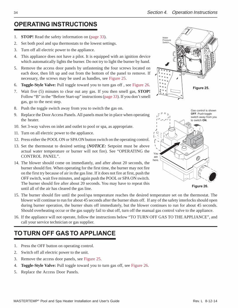
MASTERTEMP® Pool and Spa Heater Installation and User’s Guide Rev. L 8-12-14
34
WaterPressureSwitch
Section 4. Operation Instructions
OPERATING INSTRUCTIONS
1. STOP! Read the safety information on (page 33).2. Set both pool and spa thermostats to the lowest settings.3. Turn off all electric power to the appliance.4. This appliance does not have a pilot. It is equipped with an ignition device
which automatically lights the burner. Do not try to light the burner by hand.5. Remove the access door panels by unfastening the four screws located on
each door, then lift up and out from the bottom of the panel to remove. Ifnecessary, the screws may be used as handles, see Figure 25.
6. Toggle-Style Valve: Pull toggle toward you to turn gas off , see Figure 26.7. Wait five (5) minutes to clear out any gas. If you then smell gas, STOP!
Follow “B” in the “Before Start-up” instructions (page 33). If you don’t smellgas, go to the next step.
8. Push the toggle switch away from you to switch the gas on.9. Replace the Door Access Panels. All panels must be in place when operating
the heater.10. Set 3-way valves on inlet and outlet to pool or spa, as appropriate.11. Turn on all electric power to the appliance.12. Press either the POOL ON or SPA ON button switch on the operating control.13. Set the thermostat to desired setting (NOTICE: Setpoint must be above
actual water temperature or burner will not fire). See “OPERATING theCONTROL PANEL”.
14. The blower should come on immediately, and after about 20 seconds, theburner should fire. When operating for the first time, the burner may not fireon the first try because of air in the gas line. If it does not fire at first, push theOFF switch, wait five minutes, and again push the POOL or SPA ON switch.The burner should fire after about 20 seconds. You may have to repeat thisuntil all of the air has cleared the gas line.
15. The burner should fire until the pool/spa temperature reaches the desired temperature set on the thermostat. Theblower will continue to run for about 45 seconds after the burner shuts off. If any of the safety interlocks should openduring burner operation, the burner shuts off immediately, but the blower continues to run for about 45 seconds.Should overheating occur or the gas supply fail to shut off, turn off the manual gas control valve to the appliance.
16. If the appliance will not operate, follow the instructions below “TO TURN OFF GAS TO THE APPLIANCE”, andcall your service technician or gas supplier.
TO TURN OFF GAS TO APPLIANCE
1. Press the OFF button on operating control.2. Switch off all electric power to the unit.3. Remove the access door panels, see Figure 25.4. Toggle-Style Valve: Pull toggle toward you to turn gas off, see Figure 26.5. Replace the Access Door Panels.
Gas control is shownOFF. Push toggleswitch away from youto switch ON.
Youare
here.
Figure 25.
Figure 26.
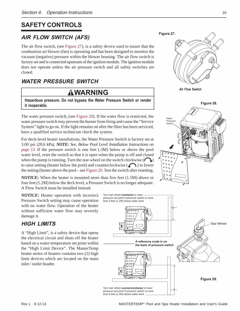
Rev. L 8-12-13 MASTERTEMP® Pool and Spa Heater Installation and User’s Guide
35
SAFETY CONTROLS
AIR FLOW SWITCH (AFS)The air flow switch, (see Figure 27), is a safety device used to insure that thecombustion air blower (fan) is operating and has been designed to monitor thevacuum (negative) pressure within the blower housing. The air flow switch isfactory set and is connected upstream of the ignition module. The ignition moduledoes not operate unless the air pressure switch and all safety switches areclosed.
WATER PRESSURE SWITCH
WARNINGHazardous pressure. Do not bypass the Water Pressure Switch or renderit inoperable.
The water pressure switch, (see Figure 28). If the water flow is restricted, thewater pressure switch may prevent the burner from firing and cause the “ServiceSystem” light to go on. If the light remains on after the filter has been serviced,have a qualified service technician check the system.
For deck-level heater installations, the Water Pressure Switch is factory set at3.00 psi (20.6 kPa). NOTE: See, Below Pool Level Installation Instructions onpage 13. If the pressure switch is one feet (.3M) below or above the poolwater level, reset the switch so that it is open when the pump is off and closedwhen the pump is running. Turn the star-wheel on the switch clockwise ( )to raise setting (heater below the pool) and counterclockwise ( ) to lowerthe setting (heater above the pool – see Figure 29. Test the switch after resetting.
NOTICE: When the heater is mounted more than five feet (1.5M) above orfour feet (1.2M) below the deck level, a Pressure Switch is no longer adequate.A Flow Switch must be installed instead.
NOTICE: Heater operation with incorrectPressure Switch setting may cause operationwith no water flow. Operation of the heaterwithout sufficient water flow may severelydamage it.
HIGH LIMITSA “High Limit”, is a safety device that opensthe electrical circuit and shuts off the heaterbased on a water temperature set point withinthe “High Limit Device”. The MasterTempheater series of heaters contains two (2) highlimit devices which are located on the maininlet / outlet header.
Air Flow Switch
Section 4. Operation Instructions
Figure 28.
WaterPressureSwitch
Star Wheel
A reference scale is onthe back of pressure switch
Turn star wheel clockwise to raisepressure set point if pressure switch is morethan 4 feet (1.2M) below water level
Turn star wheel counterclockwise to lowerpressure set point if pressure switch is morethan 5 feet (1.5M) above water level
Figure 29.
Figure 27.
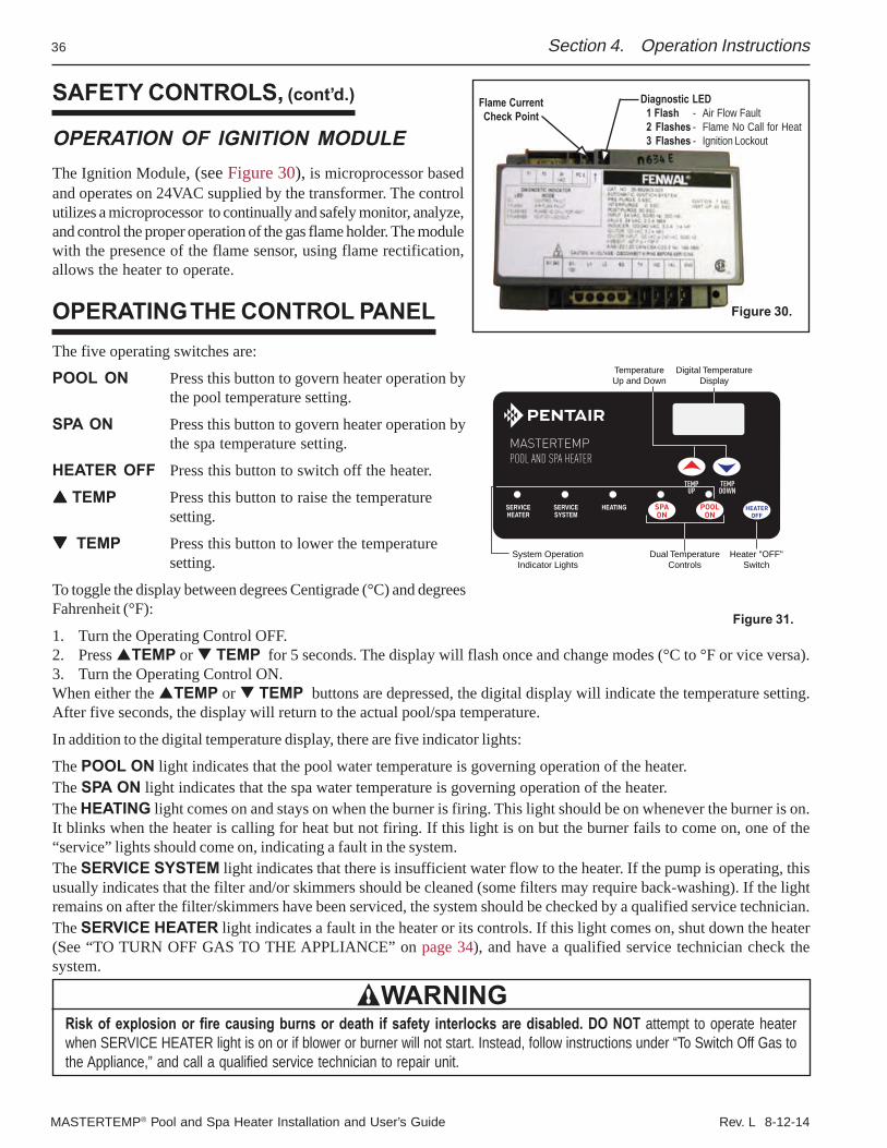
MASTERTEMP® Pool and Spa Heater Installation and User’s Guide Rev. L 8-12-14
36
Diagnostic LED1 Flash - Air Flow Fault2 Flashes - Flame No Call for Heat3 Flashes - Ignition Lockout
Flame CurrentCheck Point
Section 4. Operation Instructions
Figure 30.
SAFETY CONTROLS, (cont’d.)
OPERATION OF IGNITION MODULEThe Ignition Module, (see Figure 30), is microprocessor basedand operates on 24VAC supplied by the transformer. The controlutilizes a microprocessor to continually and safely monitor, analyze,and control the proper operation of the gas flame holder. The modulewith the presence of the flame sensor, using flame rectification,allows the heater to operate.
OPERATING THE CONTROL PANELThe five operating switches are:
POOL ON Press this button to govern heater operation bythe pool temperature setting.
SPA ON Press this button to govern heater operation bythe spa temperature setting.
HEATER OFF Press this button to switch off the heater.
TEMP Press this button to raise the temperaturesetting.
TEMP Press this button to lower the temperaturesetting.
To toggle the display between degrees Centigrade (°C) and degreesFahrenheit (°F):
1. Turn the Operating Control OFF.2. Press TEMP or TEMP for 5 seconds. The display will flash once and change modes (°C to °F or vice versa).3. Turn the Operating Control ON.When either the TEMP or TEMP buttons are depressed, the digital display will indicate the temperature setting.After five seconds, the display will return to the actual pool/spa temperature.
In addition to the digital temperature display, there are five indicator lights:
The POOL ON light indicates that the pool water temperature is governing operation of the heater.The SPA ON light indicates that the spa water temperature is governing operation of the heater.The HEATING light comes on and stays on when the burner is firing. This light should be on whenever the burner is on.It blinks when the heater is calling for heat but not firing. If this light is on but the burner fails to come on, one of the“service” lights should come on, indicating a fault in the system.The SERVICE SYSTEM light indicates that there is insufficient water flow to the heater. If the pump is operating, thisusually indicates that the filter and/or skimmers should be cleaned (some filters may require back-washing). If the lightremains on after the filter/skimmers have been serviced, the system should be checked by a qualified service technician.The SERVICE HEATER light indicates a fault in the heater or its controls. If this light comes on, shut down the heater(See “TO TURN OFF GAS TO THE APPLIANCE” on page 34), and have a qualified service technician check thesystem.
WARNINGRisk of explosion or fire causing burns or death if safety interlocks are disabled. DO NOT attempt to operate heaterwhen SERVICE HEATER light is on or if blower or burner will not start. Instead, follow instructions under “To Switch Off Gas tothe Appliance,” and call a qualified service technician to repair unit.
Figure 31.
TemperatureUp and Down
Digital TemperatureDisplay
System OperationIndicator Lights
Dual TemperatureControls
Heater "OFF"Switch
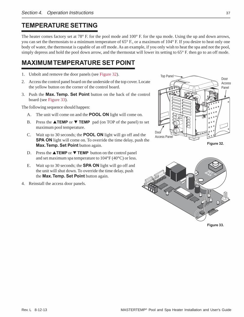
Rev. L 8-12-13 MASTERTEMP® Pool and Spa Heater Installation and User’s Guide
37
TEMPERATURE SETTINGThe heater comes factory set at 78° F. for the pool mode and 100° F. for the spa mode. Using the up and down arrows,you can set the thermostats to a minimum temperature of 65° F., or a maximum of 104° F. If you desire to heat only onebody of water, the thermostat is capable of an off mode. As an example, if you only wish to heat the spa and not the pool,simply depress and hold the pool down arrow, and the thermostat will lower its setting to 65° F. then go to an off mode.
MAXIMUM TEMPERATURE SET POINT1. Unbolt and remove the door panels (see Figure 32).
2. Access the control panel board on the underside of the top cover. Locatethe yellow button on the corner of the control board.
3. Push the Max. Temp. Set Point button on the back of the controlboard (see Figure 33).
The following sequence should happen:
A. The unit will come on and the POOL ON light will come on.
B. Press the TEMP or TEMP pad (on TOP of the panel) to setmaximum pool temperature.
C. Wait up to 30 seconds; the POOL ON light will go off and theSPA ON light will come on. To override the time delay, push theMax. Temp. Set Point button again.
D. Press the TEMP or TEMP button on the control paneland set maximum spa temperature to 104°F (40°C) or less.
E. Wait up to 30 seconds; the SPA ON light will go off andthe unit will shut down. To override the time delay, pushthe Max. Temp. Set Point button again.
4. Reinstall the access door panels.
Section 4. Operation Instructions
DoorAccessPanel
Top Panel
DoorAccess Panel
Figure 32.
S1SETMAX
S1
SETMAX
Figure 33.
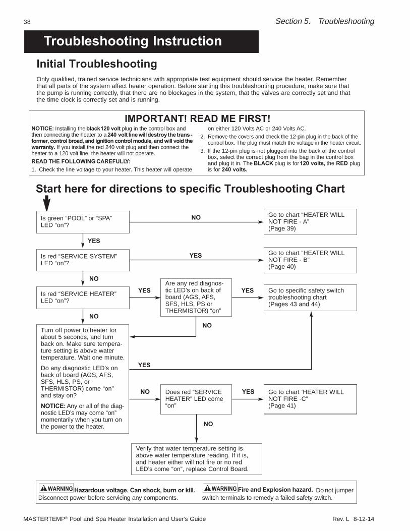
MASTERTEMP® Pool and Spa Heater Installation and User’s Guide Rev. L 8-12-14
38 Section 5. Troubleshooting
Troubleshooting Instruction
Hazardous voltage. Can shock, burn or kill. Disconnect power before servicing any components.
Do not jumperswitch terminals to remedy a failed safety switch.
WARNING WARNING
Initial TroubleshootingOnly qualified, trained service technicians with appropriate test equipment should service the heater. Rememberthat all parts of the system affect heater operation. Before starting this troubleshooting procedure, make sure thatthe pump is running correctly, that there are no blockages in the system, that the valves are correctly set and thatthe time clock is correctly set and is running.
Go to chart “HEATER WILLNOT FIRE - A”(Page 39)
Go to chart “HEATER WILLNOT FIRE - B” (Page 40)
Go to specific safety switchtroubleshooting chart (Pages 43 and 44)
Go to chart ‘HEATER WILLNOT FIRE -C” (Page 41)
Are any red diagnos-tic LED’s on back ofboard (AGS, AFS,SFS, HLS, PS orTHERMISTOR) “on”
NO
NO
NONO
NO
YES
YES
YES
NO
YES
YES
Does red “SERVICEHEATER” LED come“on”
Verify that water temperature setting isabove water temperature reading. If it is, and heater either will not fire or no red LED’s come “on”, replace Control Board.
YES
Is green “POOL” or “SPA”LED “on”?
Is red “SERVICE SYSTEM”LED “on”?
Is red “SERVICE HEATER”LED “on”?
Turn off power to heater forabout 5 seconds, and turnback on. Make sure tempera-ture setting is above watertemperature. Wait one minute.
Do any diagnostic LED’s onback of board (AGS, AFS,SFS, HLS, PS, or THERMISTOR) come “on”and stay on?
NOTICE: Any or all of the diag-nostic LED’s may come “on”momentarily when you turn onthe power to the heater.
NOTICE: Installing the black 120 volt plug in the control box andthen connecting the heater to a 240 volt line will destroy the trans-former, control broad, and ignition control module, and will void thewarranty. If you install the red 240 volt plug and then connect theheater to a 120 volt line, the heater will not operate.READ THE FOLLOWING CAREFULLY:1. Check the line voltage to your heater. This heater will operate
on either 120 Volts AC or 240 Volts AC. 2. Remove the covers and check the 12-pin plug in the back of the
control box. The plug must match the voltage in the heater circuit.3. If the 12-pin plug is not plugged into the back of the control
box, select the correct plug from the bag in the control boxand plug it in. The BLACK plug is for 120 volts, the RED plugis for 240 volts.
IMPORTANT! READ ME FIRST!
Start here for directions to specific Troubleshooting Chart
Fire and Explosion hazard.
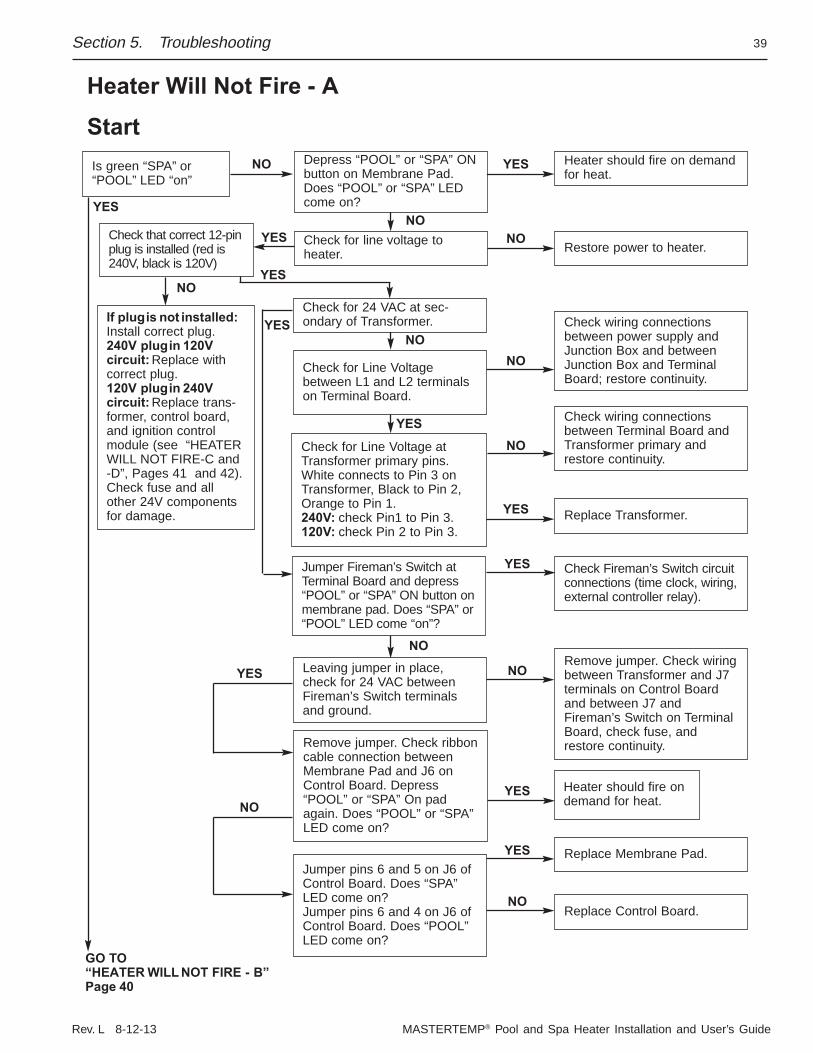
Rev. L 8-12-13 MASTERTEMP® Pool and Spa Heater Installation and User’s Guide
39Section 5. Troubleshooting
Heater Will Not Fire - A
Start
GO TO“HEATER WILL NOT FIRE - B”Page 40
Heater should fire on demandfor heat.
Check Fireman’s Switch circuitconnections (time clock, wiring,external controller relay).
Remove jumper. Check wiringbetween Transformer and J7terminals on Control Boardand between J7 andFireman’s Switch on TerminalBoard, check fuse, andrestore continuity.
Restore power to heater.
Replace Transformer.
Heater should fire ondemand for heat.
Replace Control Board.
Replace Membrane Pad.
Check wiring connectionsbetween power supply andJunction Box and betweenJunction Box and TerminalBoard; restore continuity.
Check wiring connectionsbetween Terminal Board andTransformer primary andrestore continuity.
Is green “SPA” or“POOL” LED “on”
YES
NO
NO
YES
YES
YES
NO
NO
Depress “POOL” or “SPA” ONbutton on Membrane Pad.Does “POOL” or “SPA” LEDcome on?
Check for line voltage toheater.
Check for 24 VAC at sec-ondary of Transformer.
Check for Line Voltage atTransformer primary pins.White connects to Pin 3 onTransformer, Black to Pin 2,Orange to Pin 1.240V: check Pin1 to Pin 3.120V: check Pin 2 to Pin 3.
Jumper Fireman’s Switch atTerminal Board and depress“POOL” or “SPA” ON button onmembrane pad. Does “SPA” or“POOL” LED come “on”?
Leaving jumper in place,check for 24 VAC betweenFireman’s Switch terminalsand ground.
Jumper pins 6 and 5 on J6 ofControl Board. Does “SPA”LED come on?Jumper pins 6 and 4 on J6 ofControl Board. Does “POOL”LED come on?
Check for Line Voltagebetween L1 and L2 terminalson Terminal Board.
NOYES
NO
NO
YES
YES
YES
YES
YES
NO
NO
YES
NO
Check that correct 12-pinplug is installed (red is240V, black is 120V)
If plug is not installed:Install correct plug.240V plug in 120Vcircuit: Replace withcorrect plug.120V plug in 240Vcircuit: Replace trans-former, control board,and ignition controlmodule (see “HEATERWILL NOT FIRE-C and-D”, Pages 41 and 42).Check fuse and allother 24V componentsfor damage.
Remove jumper. Check ribboncable connection betweenMembrane Pad and J6 onControl Board. Depress“POOL” or “SPA” On padagain. Does “POOL” or “SPA”LED come on?
NO
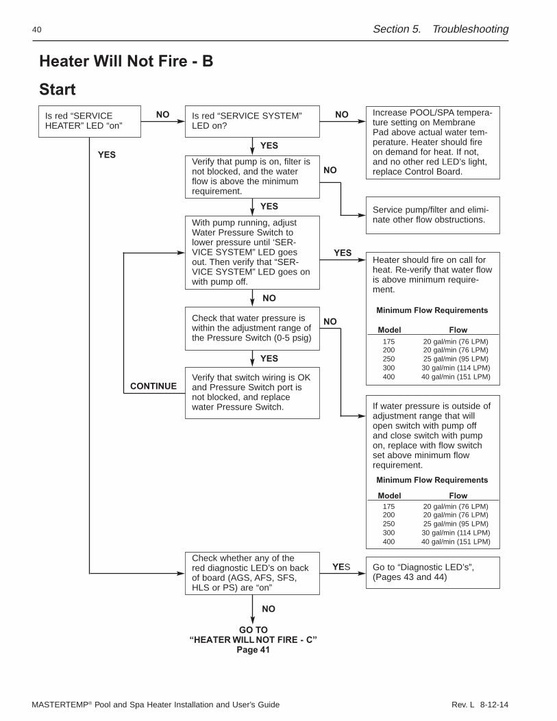
MASTERTEMP® Pool and Spa Heater Installation and User’s Guide Rev. L 8-12-14
40
Heater Will Not Fire - B
StartIncrease POOL/SPA tempera-ture setting on MembranePad above actual water tem-perature. Heater should fireon demand for heat. If not,and no other red LED’s light,replace Control Board.
Service pump/filter and elimi-nate other flow obstructions.
Heater should fire on call forheat. Re-verify that water flowis above minimum require-ment.
Minimum Flow Requirements
Model Flow
200 20 gal/min (76 LPM)175 20 gal/min (76 LPM)
250 25 gal/min (95 LPM)300 30 gal/min (114 LPM)400 40 gal/min (151 LPM)
If water pressure is outside ofadjustment range that willopen switch with pump offand close switch with pumpon, replace with flow switchset above minimum flowrequirement.
Model Flow
200 20 gal/min (76 LPM)175 20 gal/min (76 LPM)
250 25 gal/min (95 LPM)300 30 gal/min (114 LPM)400 40 gal/min (151 LPM)
Is red “SERVICEHEATER” LED “on”
YES
YES
NO
YES
NO
NO
Is red “SERVICE SYSTEM”LED on?
Verify that pump is on, filter isnot blocked, and the waterflow is above the minimumrequirement.
Check that water pressure iswithin the adjustment range ofthe Pressure Switch (0-5 psig)
Verify that switch wiring is OKand Pressure Switch port isnot blocked, and replacewater Pressure Switch.
Check whether any of thered diagnostic LED’s on backof board (AGS, AFS, SFS,HLS or PS) are “on”
GO TO“HEATER WILL NOT FIRE - C”
Page 41
Go to “Diagnostic LED’s”,(Pages 43 and 44)
With pump running, adjustWater Pressure Switch tolower pressure until ‘SER-VICE SYSTEM” LED goesout. Then verify that “SER-VICE SYSTEM” LED goes onwith pump off.
YES
YES
YES
NO
NO
NO
CONTINUE
Minimum Flow Requirements
Section 5. Troubleshooting
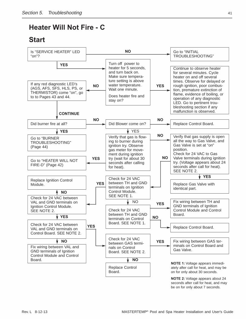
Rev. L 8-12-13 MASTERTEMP® Pool and Spa Heater Installation and User’s Guide
41
Heater Will Not Fire - C
StartGo to “INITIALTROUBLESHOOTING”
Continue to observe heaterfor several minutes. Cycleheater on and off severaltimes. Observe for delayed orrough ignition, poor combus-tion, premature extinction offlame, evidence of boiling, oroperation of any diagnosticLED. Go to pertinent trou-bleshooting section if anymalfunction is observed.
Replace Control Board.
Replace Gas Valve with identical part.
Fix wiring between TH andGND terminals of IgnitionControl Module and ControlBoard.
Replace Control Board.
Fix wiring between GAS ter-minals on Control Board andGas Valve.
NOTE 1: Voltage appears immedi-ately after call for heat, and may beon for only about 30 seconds.
NOTE 2: Voltage appears about 24seconds after call for heat, and maybe on for only about 7 seconds.
Verify that gas supply is openall the way to Gas Valve, andGas Valve is set at “on” position.Check for 24 VAC to GasValve terminals during ignitiontry. (Voltage appears about 24seconds after call for heat).SEE NOTE 2.
Turn off power toheater for 5 seconds,and turn back on.Make sure tempera-ture setting is abovewater temperature.Wait one minute.
Does heater fire andstay on?
Did Blower come on?
Verify that gas is flow-ing to burner duringignition try. Observegas meter for move-ment during ignitiontry (wait for about 30seconds after callingfor heat).
Check for 24 VACbetween TH and GNDterminals on IgnitionControl Module. SEE NOTE 1.
Check for 24 VACbetween TH and GNDterminals on ControlBoard. SEE NOTE 1.
Check for 24 VACbetween GAS termi-nals on ControlBoard. SEE NOTE 2.
Replace ControlBoard.
NO
CONTINUE
YES
YES YES
NO
NO
YES
NO
YES
NO
NO
YES
YES
NO
YES
YES
Is “SERVICE HEATER” LED“on”?
Go to “BURNERTROUBLESHOOTING”(Page 44)
Go to “HEATER WILL NOTFIRE-D” (Page 42)
Check for 24 VAC betweenVAL and GND terminals onIgnition Control Module. SEE NOTE 2.
Check for 24 VAC betweenVAL and GND terminals onControl Board. SEE NOTE 2.
If any red diagnostic LED’s(AGS, AFS, SFS, HLS, PS, orTHERMISTOR) come “on”, goto to Pages 43 and 44.
Did burner fire at all?
Replace Ignition ControlModule.
NO
YES
Fix wiring between VAL andGND terminals of IgnitionControl Module and ControlBoard.
NO
YES
NO
NO
Section 5. Troubleshooting
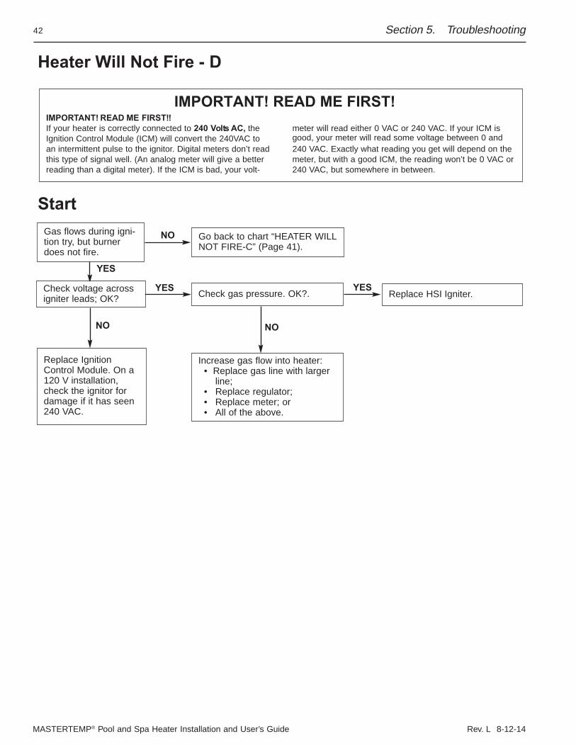
MASTERTEMP® Pool and Spa Heater Installation and User’s Guide Rev. L 8-12-14
42
Heater Will Not Fire - D
Start
IMPORTANT! READ ME FIRST!!If your heater is correctly connected to 240 Volts AC, theIgnition Control Module (ICM) will convert the 240VAC toan intermittent pulse to the ignitor. Digital meters don’t readthis type of signal well. (An analog meter will give a betterreading than a digital meter). If the ICM is bad, your volt-
meter will read either 0 VAC or 240 VAC. If your ICM isgood, your meter will read some voltage between 0 and240 VAC. Exactly what reading you get will depend on themeter, but with a good ICM, the reading won’t be 0 VAC or240 VAC, but somewhere in between.
IMPORTANT! READ ME FIRST!
Gas flows during igni-tion try, but burnerdoes not fire.
NO
NO
YES
Go back to chart “HEATER WILLNOT FIRE-C” (Page 41).
Check voltage acrossigniter leads; OK?
Replace IgnitionControl Module. On a120 V installation,check the ignitor fordamage if it has seen240 VAC.
NO
YESReplace HSI Igniter.Check gas pressure. OK?.
Increase gas flow into heater: • Replace gas line with larger
line;• Replace regulator;• Replace meter; or• All of the above.
YES
Section 5. Troubleshooting
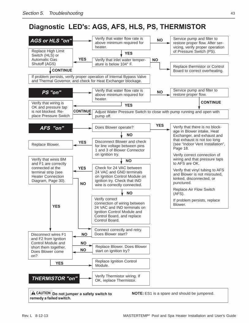
Rev. L 8-12-13 MASTERTEMP® Pool and Spa Heater Installation and User’s Guide
43
Diagnostic LED's: AGS, AFS, HLS, PS, THERMISTOR
Do not jumper a safety switch toremedy a failed switch.
NOTE: ES1 is a spare and should be jumpered.CAUTION
Service pump and filter torestore proper flow. After ser-vicing, verify proper operationof Pressure Switch (PS).
Replace thermistor or ControlBoard to correct overheating.
Replace High LimitSwitch (HLS) orAutomatic GasShutoff (AGS)
If problem persists, verify proper operation of Internal Bypass Valveand Thermal Governor, and check for Heat Exchanger blockage.
YES
NO
NO
AGS or HLS "on" Verify that water flow rate isabove minimum required forheater.
Verify that inlet water temper-ature is below 104° F.
YES
CONTINUE
YES
CONTINUE
Verify that there is no block-age in Blower intake, HeatExchanger, and exhaust andthat exhaust is not too long(see “Indoor Vent Installation”,Page 18.
Verify correct connection ofwiring and that pressure tapsto AFS are OK.
Verify that vinyl tubing to AFSand Blower is not misrouted,kinked, disconnected, orpunctured.
Replace Air Flow Switch(AFS).
If problem persists, replaceBlower.
Replace Blower.
Verify correctconnection of wiring between24 VAC and IND terminals onIgnition Control Module andControl Board, and replaceControl Board.
YES
YES
NO
NO
NO
YES
YES
NO
AFS "on" Does Blower operate?
THERMISTOR "on" Verify Thermistor wiring. IfOK, replace Thermistor.
Disconnect Blower and checkfor line voltage between pins1 and 3 of Blower Connectoron ignition try.
Connect correctly and retry.Does Blower start?
Replace Blower. Does Blowerstart on ignition try?
Replace Ignition ControlModule.
NO
Verify that wires BMand F1 are correctlyconnected at the terminal strip (seeHeater ConnectionDiagram, Page 30).
Disconnect wires F1and F2 from IgnitionControl Module andshort them together.Does Blower comeon?
Check for 24 VAC between24 VAC and GND terminalson Ignition Control Module onignition try. Check that INDwire is correctly connected.
NO
NO
Service pump and filter torestore proper flow.
Verify that wiring isOK and pressure tapis not blocked. Re-place Pressure Switch
CONTINUE
NOPS "on" Verify that water flow rate isabove minimum required forheater.
Adjust Water Pressure Switch to close with pump running and open withpump off.
YES
Section 5. Troubleshooting
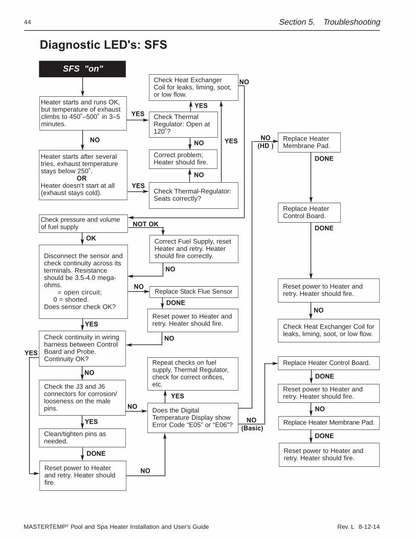
MASTERTEMP® Pool and Spa Heater Installation and User’s Guide Rev. L 8-12-14
44
Diagnostic LED's: SFS
NO(HD )
NO(Basic)
NO
Reset power to Heater andretry. Heater should fire.
Does the DigitalTemperature Display showError Code “E05” or “E06”?
Heater starts and runs OK,but temperature of exhaustclimbs to 450˚–500˚ in 3–5minutes.
Heater starts after severaltries, exhaust temperaturestays below 250˚.
ORHeater doesn’t start at all(exhaust stays cold).
Check pressure and volumeof fuel supply
Check the J3 and J6 connectors for corrosion/looseness on the malepins.
Check continuity in wiringharness between ControlBoard and Probe.Continuity OK?
Disconnect the sensor andcheck continuity across itsterminals. Resistanceshould be 3.5-4.0 mega-ohms.
= open circuit; 0 = shorted.
Does sensor check OK?
Clean/tighten pins asneeded.
Reset power to Heaterand retry. Heater shouldfire.
NOT OK
NO
NO
NO
NO
NO
SFS "on"
Replace Stack Flue Sensor
Correct Fuel Supply, resetHeater and retry. Heatershould fire correctly.
Repeat checks on fuel supply, Thermal Regulator,check for correct orifices,etc.
DONE
DONE
YES
YESYES
YESNO
NOYES
NO
OK
YES
Replace HeaterControl Board.
Replace HeaterMembrane Pad.
Reset power to Heater andretry. Heater should fire.
Check Heat Exchanger Coil forleaks, liming, soot, or low flow.
Correct problem;Heater should fire.
Check Heat ExchangerCoil for leaks, liming, soot,or low flow.
Check ThermalRegulator: Open at120˚?
Check Thermal-Regulator:Seats correctly?
DONE
NO
DONE
Replace Heater Membrane Pad.
Replace Heater Control Board.
Reset power to Heater andretry. Heater should fire.
Reset power to Heater andretry. Heater should fire.
DONE
NO
YES
YES
DONE
NO
Section 5. Troubleshooting
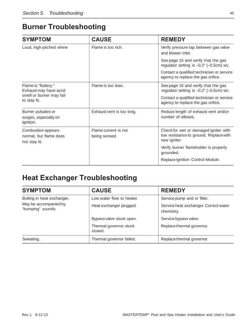
Rev. L 8-12-13 MASTERTEMP® Pool and Spa Heater Installation and User’s Guide
45
Burner TroubleshootingSYMPTOM CAUSE REMEDYLoud, high-pitched whine Flame is too rich. Verify pressure tap between gas valve
and blower inlet.
See page 15 and verify that the gasregulator setting is –0.2" (–0.5cm) wc.
Flame is “fluttery .” Flame is too lean. See page 16 and verify that the gasExhaust may have acrid regulator setting is –0.2" (–0.5cm) wc. smell or burner may failto stay lit.
Burner pulsates or Exhaust vent is too long. Reduce length of exhaust vent and/orsurges, especially on number of elbows.ignition.
Combustion appears Flame current is not Check for wet or damaged igniter withnormal, but flame does being sensed. low resistance to ground. Replacewithnot stay lit. new igniter.
Verify burner flameholder is properlygrounded.
Ignition Control Module.
Heat Exchanger TroubleshootingSYMPTOM CAUSE REMEDYBoiling in heat exchanger. Low water flow to heater. pump and or filter.May be accompanied by Heat exchanger plugged. Service
Service
heat exchanger. Correct water“bumping” sounds. chemistry.
Bypass valve stuck open. Service bypass valve.
Thermal governor stuck Replace
Replace
Replace
Contact a qualified technician or serviceagency to replace the gas orifice.
Contact a qualified technician or serviceagency to replace the gas orifice.
thermal governor.closed.
Sweating. Thermal governor failed. thermal governor.
Section 5. Troubleshooting
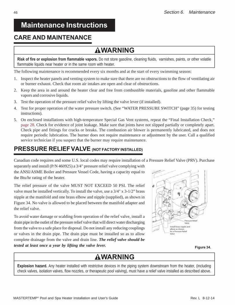
MASTERTEMP® Pool and Spa Heater Installation and User’s Guide Rev. L 8-12-14
46
Maintenance InstructionsCARE AND MAINTENANCE
WARNINGRisk of fire or explosion from flammable vapors. Do not store gasoline, cleaning fluids, varnishes, paints, or other volatileflammable liquids near heater or in the same room with heater.
The following maintenance is recommended every six months and at the start of every swimming season:
1. Inspect the heater panels and venting system to make sure that there are no obstructions to the flow of ventilating airor burner exhaust. Check that room air intakes are open and clear of obstructions.
2. Keep the area in and around the heater clear and free from combustible materials, gasoline and other flammablevapors and corrosive liquids.
3. Test the operation of the pressure relief valve by lifting the valve lever (if installed).4. Test for proper operation of the water pressure switch. (See “WATER PRESSURE SWITCH” (page 35) for testing
instructions).5. On enclosed installations with high-temperature Special Gas Vent systems, repeat the “Final Installation Check,”
page 28. Check for evidence of joint leakage. Make sure that joints have not slipped partially or completely apart.Check pipe and fittings for cracks or breaks. The combustion air blower is permanently lubricated, and does notrequire periodic lubrication. The burner does not require maintenance or adjustment by the user. Call a qualifiedservice technician if you suspect that the burner may require maintenance.
PRESSURE RELIEF VALVE (NOT FACTORY INSTALLED)
Canadian code requires and some U.S. local codes may require installation of a Pressure Relief Valve (PRV). Purchaseseparately and install (P/N 460925) a 3/4" pressure relief valve complying withthe ANSI/ASME Boiler and Pressure Vessel Code, having a capacity equal tothe Btu/hr rating of the heater.
The relief pressure of the valve MUST NOT EXCEED 50 PSI. The reliefvalve must be installed vertically. To install the valve, use a 3/4" x 3-1/2” brassnipple at the manifold and one brass elbow and nipple (supplied), as shown inFigure 34. No valve is allowed to be placed between the manifold adapter andthe relief valve.
To avoid water damage or scalding from operation of the relief valve, install adrain pipe in the outlet of the pressure relief valve that will direct water dischargingfrom the valve to a safe place for disposal. Do not install any reducing couplingsor valves in the drain pipe. The drain pipe must be installed so as to allowcomplete drainage from the valve and drain line. The relief valve should betested at least once a year by lifting the valve lever.
WARNINGExplosion hazard. Any heater installed with restrictive devices in the piping system downstream from the heater, (includingcheck valves, isolation valves, flow nozzles, or therapeutic pool valving), must have a relief valve installed as described above.
Section 6. Maintenance
Figure 34.
Install brass nipple andelbow as shown,for a Pressure ReliefValve
Pressure ReliefValve
Rev. L 8-12-13 MASTERTEMP® Pool and Spa Heater Installation and User’s Guide
47Section 6. Maintenance
AFTER START-UP
CHECKING WATER FLOWWARNING
Fire or flooding hazard. If the unit overheats and the burner fails to shut off, follow instructions under “To Turn Off Gas to theAppliance”, page 34, and call a qualified service technician to repair unit.
After start-up, the outlet water pipe should feel slightly warmer than the inlet pipe. If it feels hot, or if you hear the water in the heaterboiling, there may not be enough water flow to the appliance. Make sure that the filter is not plugged. If water temperature remains highbut the unit continues to operate, turn off the appliance and call your service technician.
SPRING AND FALL OPERATIONIf the pool is only used occasionally, lower the pool thermostat to 68° F (20° C) and leave the heater on. This will keep the pool and thesurrounding ground warm enough so that the heater should restore the pool to a comfortable temperature within about one day.
WINTER OPERATIONCAUTION
• Operating this heater continuously at water temperatures below 68° F. (20° C) will cause harmful condensation and will damagethe heater and void the warranty.
• If the heater has been drained for freezing condition, do NOT turn "ON" until the system is circulating water.• Water trapped in the heat exchanger can result in freeze damage to the exchanger or headers. Freeze damage is specifically not
covered by the warranty.• When starting the heater for the swimming season with a water temperature below 50° F (10° C), the heater may be used to heat
the water; however, make sure that the heater operates continuously until the water temperature reaches the heater’s minimumsetting of 68° F (20° C). During cold weather, if there is no danger of freezing, operate the filter pump continuously even if theheater is not operating. If air temperatures are expected to drop below freezing (32° F/0° C), shut down the heater and winterizeit.
For outdoor heaters in freezing climates, shut the heater down and drain it for winter as follows:1. Turn off electrical supply to the heater and pump.2. Close main gas control valve and manual gas valve (located outside the heater). Turn switch on heater gas valve to OFF.3. In northern climates where they may be required, open drain cock located on the bottom of the manifold adapter, and drain the heat
exchanger and manifold adapter completely. If heater is below pool water level, be sure to close isolation valves to prevent drainingthe pool (isolation valves are not required and should not be used on heaters installed above pool water level except when neededfor winterizing valves). Assist the draining by blowing out the heat exchanger through the pressure switch fitting with low pressurecompressed air (less than 5 PSI or 35 kPa).
WARNINGExplosion hazard. Purging the system with compressed air can cause components to explode, with risk of severe injury ordeath to anyone nearby. Use only a low pressure (below 5 PSI or 35 kPa), high volume blower when air purging the heater,pump, filter, or piping.
4. Remove the Water Pressure Switch. Plug the port in the manifold to prevent bugs and dirt from getting into the manifold.5. Drain the plastic inlet/outlet manifold through the outlet pipe. If the pipe does not drain naturally to the pool, install a drain cock
in the outlet pipe to drain the manifold.6. Cover air inlet grate with a plastic bag to prevent bugs, leaves, etc., from getting into the heater.NOTICE: Water trapped in the heater can cause freeze damage. Allowing the heater to freeze voids the warranty.To return the heater to service after winterizing:1. Close drain cock and fittings.2. Before starting the heater, circulate water through the heater for several minutes until all air noises stop. See also “BEFORE
START-UP” (page 33) and “CARE AND MAINTENANCE” (page 46).
(See additional notes under Important Notices in Introduction.)
MASTERTEMP® Pool and Spa Heater Installation and User’s Guide Rev. L 8-12-14
48
MAINTAINING POOL TEMPERATURETo maintain pool temperature, make sure that the heater switch and valving are reset to pool settings after using the spa.
ENERGY SAVING TIPS1. Keep the pool or spa covered when not in use. This will reduce heating costs, reduce water evaporation, conserve
chemicals and reduce load on the filtering system.
2. Reduce pool thermostat to 78° F (25° C) or lower; reduce spa temperature to 100° F (38° C). This is accepted asbeing the most healthy temperature for swimming by the American Red Cross.
3. Use a time clock to start the filter pump at 6 a.m. or later. The swimming pool loses less heat after daybreak.
4. For pools used only on weekends, lower the thermostat setting by 10° F to 15° F (5° C to 8° C) during the week toreduce heat loss. A properly sized heater will restore normal temperature within one day.
5. Turn the heater off when the pool will not be used for an extended period.
6. Follow a regular program of preventive maintenance for the heater each new swimming season. Check operation ofthe heater and its controls.
CHEMICAL BALANCE
POOL AND SPA WATERYour pool heater was designed specifically for your spa or pool and will give you many years of trouble-free service,provided you keep your water chemistry in proper condition.
Water chemistry should follow good swimming pool water chemistry practices. When using a chlorinator, install it downstream from the heater and at a lower level than the heater outlet. Install a corrosion resistant positive seal “CheckValve”, (P/N R172288), between the heater and the chlorinator to prevent concentrated chemicals from back-siphoninginto the heater. Back-siphoning is most likely to occur when the pump stops, creating a pressure-suction differential. DoNOT sanitize the pool by putting chlorine tablets or sticks into the skimmer(s). When the pump is off, this will cause a highconcentration of chlorine to enter the heater, which could cause corrosion damage to the heat exchanger.
Three major items that can cause problems with your pool heater are: improper pH, disinfectant residual, and totalalkalinity. These items, if not kept properly balanced, can shorten the life of the heater and cause permanent damage.
CAUTIONHeat exchanger damage resulting from chemical imbalance is not covered by the warranty.
WHAT A DISINFECTANT DOESTwo pool guests you do not want are algae and bacteria. To get rid of them and make pool water sanitary for swimming- as well as to improve the water's taste, odor and clarity - some sort of disinfectant must be used.
Chlorine and bromine are universally approved by health authorities and are accepted disinfecting agents for bacteriacontrol.
WHAT IS A DISINFECTANT RESIDUAL?When you add chlorine or bromine to the pool water, a portion of the disinfectant will be consumed in the process ofdestroying bacteria, algae and other oxidizable materials. The disinfectant remaining is called chlorine residual or bromineresidual. You can determine the disinfectant residual of your pool water with a reliable test kit, available from your localpool supply store.
You must maintain a disinfectant residual level adequate enough to assure a continuous kill of bacteria or virus introducedinto pool water by swimmers, through the air, from dust, rain or other sources.
Section 6. Maintenance
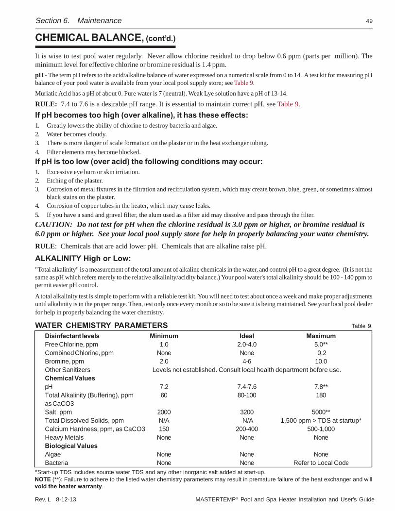
Rev. L 8-12-13 MASTERTEMP® Pool and Spa Heater Installation and User’s Guide
49
CHEMICAL BALANCE, (cont’d.)
It is wise to test pool water regularly. Never allow chlorine residual to drop below 0.6 ppm (parts per million). Theminimum level for effective chlorine or bromine residual is 1.4 ppm.pH - The term pH refers to the acid/alkaline balance of water expressed on a numerical scale from 0 to 14. A test kit for measuring pHbalance of your pool water is available from your local pool supply store; see Table 9.Muriatic Acid has a pH of about 0. Pure water is 7 (neutral). Weak Lye solution have a pH of 13-14.
RULE: 7.4 to 7.6 is a desirable pH range. It is essential to maintain correct pH, see Table 9.If pH becomes too high (over alkaline), it has these effects:1. Greatly lowers the ability of chlorine to destroy bacteria and algae.2. Water becomes cloudy.3. There is more danger of scale formation on the plaster or in the heat exchanger tubing.4. Filter elements may become blocked.If pH is too low (over acid) the following conditions may occur:1. Excessive eye burn or skin irritation.2. Etching of the plaster.3. Corrosion of metal fixtures in the filtration and recirculation system, which may create brown, blue, green, or sometimes almost
black stains on the plaster.4. Corrosion of copper tubes in the heater, which may cause leaks.5. If you have a sand and gravel filter, the alum used as a filter aid may dissolve and pass through the filter.CAUTION: Do not test for pH when the chlorine residual is 3.0 ppm or higher, or bromine residual is6.0 ppm or higher. See your local pool supply store for help in properly balancing your water chemistry.RULE: Chemicals that are acid lower pH. Chemicals that are alkaline raise pH.
ALKALINITY High or Low:"Total alkalinity" is a measurement of the total amount of alkaline chemicals in the water, and control pH to a great degree. (It is not thesame as pH which refers merely to the relative alkalinity/acidity balance.) Your pool water's total alkalinity should be 100 - 140 ppm topermit easier pH control.
A total alkalinity test is simple to perform with a reliable test kit. You will need to test about once a week and make proper adjustmentsuntil alkalinity is in the proper range. Then, test only once every month or so to be sure it is being maintained. See your local pool dealerfor help in properly balancing the water chemistry.
WATER CHEMISTRY PARAMETERS
Section 6. Maintenance
Table 9.
*Start-up TDS includes source water TDS and any other inorganic salt added at start-up.NOTE (**): Failure to adhere to the listed water chemistry parameters may result in premature failure of the heat exchanger and willvoid the heater warranty.
Disinfectant levels Minimum Ideal MaximumFree Chlorine, ppm 1.0 2.0-4.0 5.0**Combined Chlorine, ppm None None 0.2Bromine, ppm 2.0 4-6 10.0Other Sanitizers Levels not established. Consult local health department before use.Chemical ValuespH 7.2 7.4-7.6 7.8**Total Alkalinity (Buffering), ppm 60 80-100 180as CaCO3Salt ppm 2000 3200 5000**Total Dissolved Solids, ppm N/A N/A 1,500 ppm > TDS at startup*Calcium Hardness, ppm, as CaCO3 150 200-400 500-1,000Heavy Metals None None NoneBiological ValuesAlgae None None NoneBacteria None None Refer to Local Code
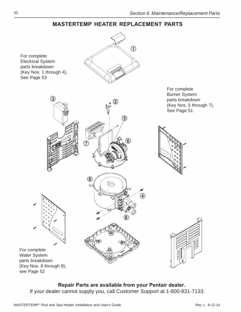
MASTERTEMP® Pool and Spa Heater Installation and User’s Guide Rev. L 8-12-14
50
MASTERTEMP HEATER REPLACEMENT PARTS
Repair Parts are available from your Pentair dealer.If your dealer cannot supply you, call Customer Support at 1-800-831-7133.
For completeElectrical System parts breakdown(Key Nos. 1 through 4),See Page 53
For completeBurner Systemparts breakdown(Key Nos. 5 through 7),See Page 51
For completeWater Systemparts breakdown(Key Nos. 8 through 9),see Page 52
1
23
5
6
4
8
9
7
Section 6. Maintenance/Replacement Parts
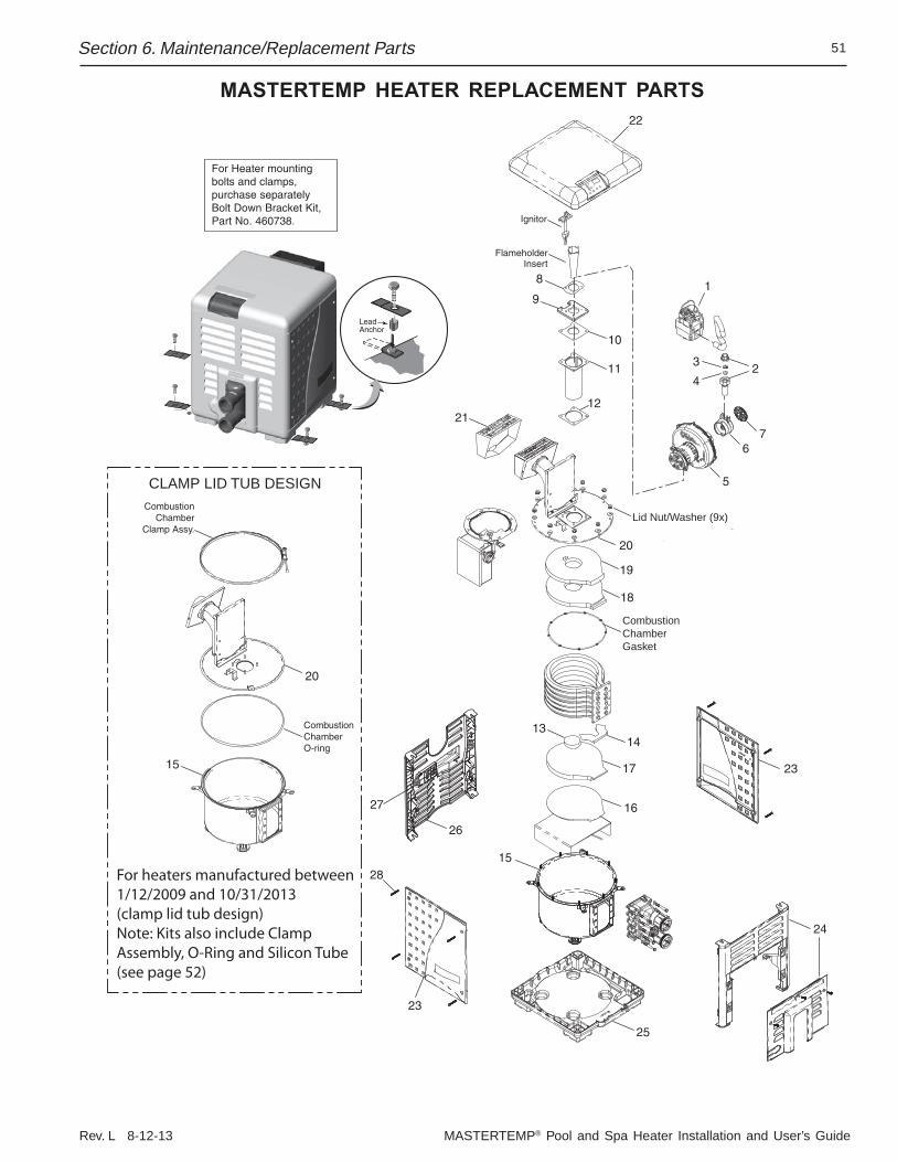
Rev. L 8-12-13 MASTERTEMP® Pool and Spa Heater Installation and User’s Guide
51
MASTERTEMP HEATER REPLACEMENT PARTS
For heaters manufactured between1/12/2009 and 10/31/2013(clamp lid tub design)Note: Kits also include Clamp Assembly, O-Ring and Silicon Tube (see page 52)
CombustionChamberGasket
Lid Nut/Washer (9x)
CLAMP LID TUB DESIGN
Section 6. Maintenance/Replacement Parts
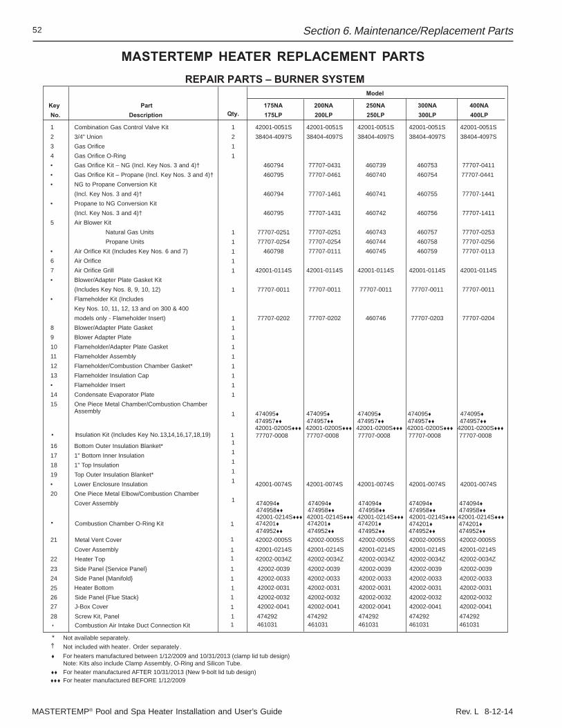
MASTERTEMP® Pool and Spa Heater Installation and User’s Guide Rev. L 8-12-14
52
MASTERTEMP HEATER REPLACEMENT PARTS
Section 6. Maintenance/Replacement Parts
REPAIR PARTS – BURNER SYSTEMModel
Key Part 200NA 250NA 300NA 400NANo. Description Qty. 200LP 250LP 300LP 400LP
1 Combination Gas Control Valve Kit 42001-0051S 42001-0051S 42001-0051S 42001-0051S2 3/4" Union
1211
11111
1
111111111
1
11111
1
38404-4097S 38404-4097S 38404-4097S 38404-4097S3 Gas Orifice4 Gas Orifice O-Ring• Gas Orifice Kit – NG (Incl. Key Nos. 3 and 4)† 77707-0431 460739 460753 77707-0411• Gas Orifice Kit – Propane (Incl. Key Nos. 3 and 4)† 77707-0461 460740 460754 77707-0441 • NG to Propane Conversion Kit
(Incl. Key Nos. 3 and 4)† 77707-1461 460741 460755 77707-1441• Propane to NG Conversion Kit
(Incl. Key Nos. 3 and 4)† 77707-1431 460742 460756 77707-14115 Air Blower Kit
Natural Gas Units 77707-0251 460743 460757 77707-0253Propane Units 77707-0254 460744 460758 77707-0256
• Air Orifice Kit (Includes Key Nos. 6 and 7) 77707-0111 460745 460759 77707-01136 Air Orifice7 Air Orifice Grill 42001-0114S 42001-0114S 42001-0114S 42001-0114S• Blower/Adapter Plate Gasket Kit
(Includes Key Nos. 8, 9, 10, 12) 77707-0011 77707-0011 77707-0011 77707-0011• Flameholder Kit (Includes
Key Nos. 10, 11, 12, 13 and on 300 & 400models only - Flameholder Insert) 77707-0202 460746 77707-0203 77707-0204
8 Blower/Adapter Plate Gasket9 Blower Adapter Plate10 Flameholder/Adapter Plate Gasket11 Flameholder Assembly12 Flameholder/Combustion Chamber Gasket*13 Flameholder Insulation Cap• Flameholder Insert14 Condensate Evaporator Plate15 One Piece Metal Chamber/Combustion Chamber
Assembly 474095 474095 474095 474095
• Insulation Kit (Includes Key No. 13, 14, 16, 17,18,19) 77707-0008 77707-0008 77707-0008 77707-0008
16 Bottom Outer Insulation Blanket*17 1" Bottom Inner Insulation18 1" Top Insulation19 Top Outer Insulation Blanket*• Lower Enclosure Insulation 42001-0074S 42001-0074S 42001-0074S 42001-0074S20 One Piece Metal Elbow/Combustion Chamber
Cover Assembly 474094 474094 474094 474094
21 Metal Vent Cover 42002-0005S 42002-0005S 42002-0005S 42002-0005SCover Assembly 42001-0214S 42001-0214S 42001-0214S 42001-0214S
22 Heater Top 42002-0034Z 42002-0034Z 42002-0034Z 42002-0034ZSide Panel {Service Panel} 42002-0039 42002-0039 42002-0039 42002-0039
24 Side Panel {Manifold} 42002-0033 42002-0033 42002-0033 42002-0033Heater Bottom 42002-0031 42002-0031 42002-0031 42002-0031
2625
23
Side Panel {Flue Stack} 42002-0032 42002-0032 42002-0032 42002-003227 J-Box Cover 42002-0041 42002-0041 42002-0041 42002-004128 Screw Kit, Panel
175NA175LP
42001-0051S38404-4097S
460794460795
460794
460795
77707-025177707-0254
460798
42001-0114S
77707-0011
77707-0202
474095
77707-0008
42001-0074S
474094
42002-0005S42001-0214S42002-0034Z42002-003942002-003342002-003142002-003242002-0041474292
* Not available separately. † Not included with heater. Order separately .
For heaters manufactured between 1/12/2009 and 10/31/2013 (clamp lid tub design) Note: Kits also include Clamp Assembly, O-Ring and Silicon Tube.
• Combustion Chamber O-Ring Kit
474958 474958 474958 474958 474958
1
1
1
1
111111
1
474957 474957 474957 474957
Combustion Air Intake Duct Connection Kit • 4610311 461031 461031 461031 461031474292 474292 474292 474292
For heater manufactured AFTER 10/31/2013 (New 9-bolt lid tub design)
474952 474952 474952 474952 474952
For heater manufactured BEFORE 1/12/2009
42001-0200S 42001-0200S 42001-0200S 42001-0200S 42001-0200S474957
42001-0214S 42001-0214S 42001-0214S 42001-0214S474201 474201 474201 474201 474201
42001-0214S
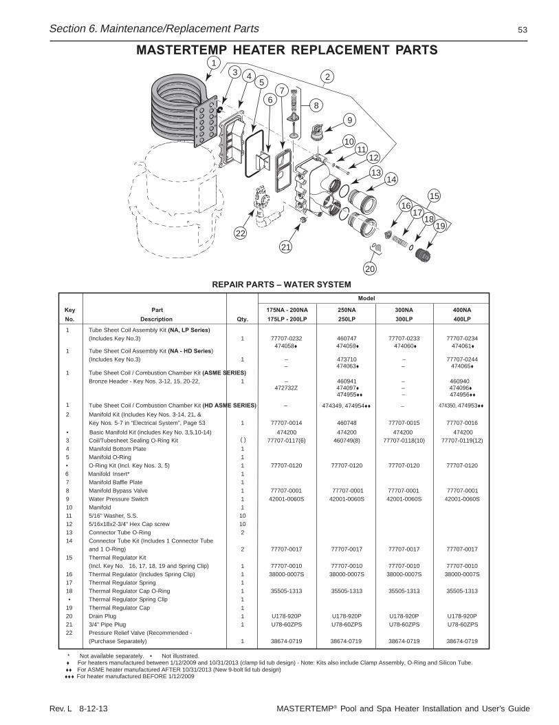
Rev. L 8-12-13 MASTERTEMP® Pool and Spa Heater Installation and User’s Guide
53
MASTERTEMP HEATER REPLACEMENT PARTS
REPAIR PARTS – WATER SYSTEM
* Not available separately. • Not illustrated.
Model
Key Part 175NA - 200NA 250NA 300NA 400NANo. Description Qty. 175LP - 200LP 250LP 300LP 400LP
1 Tube Sheet Coil Assembly Kit (NA, LP Series)(Includes Key No.3) 1 77707-0232 460747 77707-0233 77707-0234
474058 474059 474060 474061
––1 Tube Sheet Coil Assembly Kit (NA - HD Series)
(Includes Key No.3) 1 473710 77707-0244 – 474063 – 474065
13
20
2122
45
8
9
1211
10
27
6
19
14
15
13
1817
16
For heaters manufactured between 1/12/2009 and 10/31/2013 (clamp lid tub design) - Note: Kits also include Clamp Assembly, O-Ring and Silicon Tube.
2 Manifold Kit (Includes Key Nos. 3-14, 21, &Key Nos. 5-7 in “Electrical System”, Page 53 1 77707-0014 460748 77707-0015 77707-0016
3 Coil/Tubesheet Sealing O-Ring Kit 77707-0117(6) 460749(8) 77707-0118(10) 77707-0119(12)4 Manifold Bottom Plate5 Manifold O-Ring 1
1
1
• O-Ring Kit (Incl. Key Nos. 3, 5) 1 77707-0120 77707-0120 77707-0120 77707-01206 Manifold Insert* 17 Manifold Baffle Plate8 Manifold Bypass Valve 1
19 Water Pressure Switch 42001-0060S 42001-0060S 42001-0060S 42001-0060S10 Manifold 111 5/16" Washer, S.S. 1012 5/16x18x2-3/4" Hex Cap screw 1013 Connector Tube O-Ring 214 Connector Tube Kit (Includes 1 Connector Tube
and 1 O-Ring) 2 77707-0017 77707-0017 77707-0017 77707-001715 Thermal Regulator Kit
(Incl. Key No. 16, 17, 18, 19 and Spring Clip) 77707-0010 77707-0010 77707-0010 77707-001016 Thermal Regulator (Includes Spring Clip) 38000-0007S 38000-0007S 38000-0007S 38000-0007S17 Thermal Regulator Spring 1
11
18 Thermal Regulator Cap O-Ring 1 35505-1313 35505-1313 35505-1313 35505-1313• Thermal Regulator Spring Clip 1
11
19 Thermal Regulator Cap20 Drain Plug U178-920P U178-920P U178-920P U178-920P21 3/4" Pipe Plug 1 U78-60ZPS U78-60ZPS U78-60ZPS U78-60ZPS22 Pressure Relief Valve (Recommended -
(Purchase Separately) 1 38674-0719 38674-0719 38674-0719 38674-0719
• Basic Manifold Kit (includes Key No. 3,5,10-14) 474200 474200 474200 474200( )
––1 Tube Sheet Coil / Combustion Chamber Kit (ASME SERIES)
Bronze Header - Key Nos. 3-12, 15, 20-22, 1 460941 460940 472732Z 474097 – 474096
1 474349, 474954 474350, 474953––
77707-0001 77707-0001 77707-0001 77707-0001
Tube Sheet Coil / Combustion Chamber Kit (HD ASME SERIES)
For ASME heater manufactured AFTER 10/31/2013 (New 9-bolt lid tub design)For heater manufactured BEFORE 1/12/2009
474955 – 474956
Section 6. Maintenance/Replacement Parts
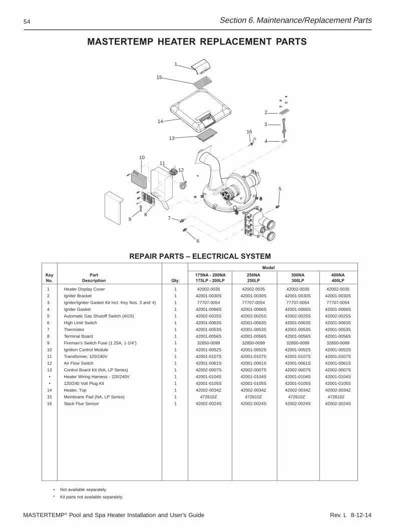
MASTERTEMP® Pool and Spa Heater Installation and User’s Guide Rev. L 8-12-14
54
MASTERTEMP HEATER REPLACEMENT PARTS
2
6
78
9
10
3
4
16
11
15
13
1
5
14
REPAIR PARTS – ELECTRICAL SYSTEMModel
Key Part 175NA - 200NA 250NA 300NA 400NANo. Description Qty. 175LP - 200LP 250LP 300LP 400LP
1 Heater Display Cover 1 42002-0035 42002-0035 42002-0035 42002-00352 Igniter Bracket 1 42001-0030S 42001-0030S 42001-0030S 42001-0030S3 Igniter/Igniter Gasket Kit Incl. Key Nos. 3 and 4) 1 77707-0054 77707-0054 77707-0054 77707-00544 Igniter Gasket 1 42001-0066S 42001-0066S 42001-0066S 42001-0066S5 Automatic Gas Shutoff Switch (AGS) 1 42002-0025S 42002-0025S 42002-0025S 42002-0025S6 High Limit Switch 1 42001-0063S 42001-0063S 42001-0063S 42001-0063S7 Thermistor 1 42001-0053S 42001-0053S 42001-0053S 42001-0053S8 Terminal Board 1
1
1
111
42001-0056S 42001-0056S 42001-0056S 42001-0056S9 Fireman’s Switch Fuse (1.25A, 1-1/4") 32850-0099 32850-0099 32850-0099 32850-009910 Ignition Control Module 1 42001-0052S 42001-0052S 42001-0052S 42001-0052S11 Transformer, 120/240V 1 42001-0107S 42001-0107S 42001-0107S 42001-0107S12 Air Flow Switch 42001-0061S 42001-0061S 42001-0061S 42001-0061S13 Control Board Kit (NA, LP Series) 1 42002-0007S 42002-0007S 42002-0007S 42002-0007S• Heater Wiring Harness - 120/240V 1 42001-0104S 42001-0104S 42001-0104S 42001-0104S• 120/240 Volt Plug Kit 42001-0105S 42001-0105S 42001-0105S 42001-0105S
14 Heater, Top 42002-0034Z 42002-0034Z 42002-0034Z 42002-0034Z15 Membrane Pad (NA, LP Series) 472610Z 472610Z 472610Z 472610Z16 Stack Flue Sensor 1 42002-0024S 42002-0024S 42002-0024S 42002-0024S
• Not available separately.
* Kit parts not available separately.
12
Section 6. Maintenance/Replacement Parts
Rev. L 8-12-13 MASTERTEMP® Pool and Spa Heater Installation and User’s Guide
55
N�TES

MASTERTEMP® Pool and Spa Heater Installation and User’s Guide Rev. L 8-12-14
56 40
*472592*
1620 HAWKINS AVE., SANFORD, NC 27330 • (919) 566-8000
10951 WEST LOS ANGELES AVE., MOORPARK, CA 93021 • (805) 553-5000
www.pentairpool.com
All Pentair trademarks and logos are owned by Pentair or by one of its global affiliates. Pentair Aquatic Systems™, MasterTemp®,
IntelliTouch®, EasyTouch®, are trademarks and/or registered trademarks of Pentair Water Pool and Spa, Inc. and/or its affiliated companies
in the United States and/ or other countries. Unless expressly noted, names and brands of third parties that may be used in this document
are not used to indicate an affiliation or endorsement between the owners of these names and brands and Pentair Water Pool and Spa, Inc.
Those names and brands may be the trademarks or registered trademarks of those third parties. Because we are continuously improving
our products and services, Pentair reserves the right to change specifications without prior notice. Pentair is an equal opportunity employer.
© 2014 Pentair Water Pool and Spa, Inc. All rights reserved. This document is subject to change without notice.
P/N 472592 REV. L 8/14