Embed Size (px)
Citation preview

MasterSeries – Retaining Wall Design
Sample Output
The following output is from the Retaining Wall Design program.
Contents
2 Reinforced Concrete Retaining Wall with sloped embankment (to BS)
4 Gravity Masonry Stepped Retaining Wall with Reinforced Concrete Base (to EC)
6 Basement Cavity Filled Masonry Propped Retaining Wall (EC)
9 RC Retaining Wall with wind on upstand (EC)
11 RC Retaining Wall with Layered Soil and Clad Front Face (BS)
13 RC Retaining Wall with Buttresses (EC)
15 Reinforcement Details DXF Output
15 Bar Bending Schedule

© MasterSeries PowerPad - My Project Title Retaining Wall Output
MasterSeries Sample Output 3 Castle Street
Carrickfergus
County Antrim BT38 7BE
Job ref : My Project
Sheet : My Walls / 2
Made By : ATW
Date : 21 June 2015/ Version 2017.10
Checked : GHB
Approved : MOG Tel: 028 9036 5950
MASTERKEY : RETAINING WALL DESIGN TO BS 8002 AND BS 8110
Basic RC Retaining Wall with sloped embankment
Summary of Design Data Notes All dimensions are in mm and all forces are per metre run Material Densities (kN/m³) Soil 18.00, Concrete 24.00 Angles Embankment 13° Concrete grade fcu 35 N/mm², Permissible tensile stress 0.250 N/mm² Concrete covers (mm) Wall inner cover 30 mm, Wall outer cover 30 mm, Base cover 50 mm Reinforcement design fy 460 N/mm² designed to BS 8110: 1997 Surcharge and Water Table Surcharge 5.00 kN/m², Fully drained Unplanned excavation depth Front of wall 330 mm † The Engineer must satisfy him/herself to the reinforcement detailing requirements of the relevant codes of practice
Soil Properties Soil bearing pressure Allowable pressure @ front 120.00 kN/m², @ back 120.00 kN/m² Back Soil Friction and Cohesion Φ = Atn(Tan(30)/1.2) = 25.69° Base Friction and Cohesion δ = Atn(0.75xTan(Atn(Tan(30)/1.2))) = 19.84° Front Soil Friction and Cohesion Φ = Atn(Tan(30)/1.2) = 25.69°
Loading Cases GSoil - Soil Self Weight, GWall - Wall & Base Self Weight, FvHeel - Vertical Loads over Heel, Pa - Active Earth Pressure, Psurcharge - Earth pressure from surcharge, Pp - Passive Earth Pressure Case 1: Geotechnical Design 1.00 GSoil+1.00 GWall+1.00 FvHeel+1.00 Pa+1.00 Psurcharge+1.00 Pp Case 2: Structural Ultimate Design 1.40 GSoil+1.40 GWall+1.60 FvHeel+1.00 Pa+1.00 Psurcharge+1.00 Pp
Geotechnical Design Wall Stability - Virtual Back Pressure
Case 1 Overturning/Stabilising 79.467/255.623 0.311 OK
Wall Sliding - Virtual Back Pressure Fx/(RxFriction + RxPassive) 59.388/(60.388+0.662) 0.973 OK
Soil Pressure Virtual Back (No uplift) Max(102.943/120, 21.021/120) kN/m² 0.858 OK Wall Back (No uplift) Max(89.917/120, 34.047/120) kN/m² 0.749 OK
Structural Design Wall Design (Inner Steel)
Critical Section Critical @ 0 mm from base, Case 2 Steel Provided (Cover) Main B16@200 (30 mm) Dist. B16@200 (46 mm) 1005 mm² OK Compression Steel Provided (Cover) Main B10@200 (30 mm) Dist. B12@200 (40 mm) 393 mm² Leverarm z=fn(d,b,As,fy,Fcu) 262 mm, 1000 mm, 1005 mm², 460 N/mm², 35.0
N/mm² 248 mm
Mr=fn(above,As',d',x,x/d) 393 mm², 35 mm, 31 mm, 0.12 108.9 kN.m Moment Capacity Check (M/Mr) M 48.9 kN.m, Mr 108.9 kN.m 0.448 OK Shear Capacity Check F 45.2 kN, vc 0.571 N/mm², Fvr 149.6 kN 0.30 OK
© MasterSeries PowerPad - My Project Title Retaining Wall Output
MasterSeries Sample Output 3 Castle Street
Carrickfergus
County Antrim BT38 7BE
Job ref : My Project
Sheet : My Walls / 3
Made By : ATW
Date : 21 June 2015/ Version 2017.10
Checked : GHB
Approved : MOG Tel: 028 9036 5950
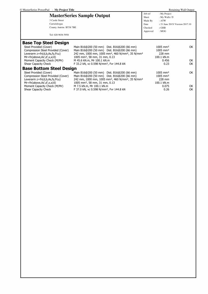
Base Top Steel Design Steel Provided (Cover) Main B16@200 (50 mm) Dist. B16@200 (66 mm) 1005 mm² OK Compression Steel Provided (Cover) Main B16@200 (50 mm) Dist. B16@200 (66 mm) 1005 mm² Leverarm z=fn(d,b,As,fy,Fcu) 242 mm, 1000 mm, 1005 mm², 460 N/mm², 35 N/mm² 228 mm Mr=fn(above,As',d',x,x/d) 1005 mm², 58 mm, 31 mm, 0.13 100.1 kN.m Moment Capacity Check (M/Mr) M 45.6 kN.m, Mr 100.1 kN.m 0.456 OK Shear Capacity Check F 33.2 kN, vc 0.598 N/mm², Fvr 144.8 kN 0.23 OK
Base Bottom Steel Design Steel Provided (Cover) Main B16@200 (50 mm) Dist. B16@200 (66 mm) 1005 mm² OK Compression Steel Provided (Cover) Main B16@200 (50 mm) Dist. B16@200 (66 mm) 1005 mm² Leverarm z=fn(d,b,As,fy,Fcu) 242 mm, 1000 mm, 1005 mm², 460 N/mm², 35 N/mm² 228 mm Mr=fn(above,As',d',x,x/d) 1005 mm², 58 mm, 31 mm, 0.13 100.1 kN.m Moment Capacity Check (M/Mr) M 7.5 kN.m, Mr 100.1 kN.m 0.075 OK Shear Capacity Check F 37.0 kN, vc 0.598 N/mm², Fvr 144.8 kN 0.26 OK
© MasterSeries PowerPad - My Project Title Retaining Wall Output
MasterSeries Sample Output 3 Castle Street
Carrickfergus
County Antrim BT38 7BE
Job ref : My Project
Sheet : My Walls / 4
Made By : ATW
Date : 21 June 2015/ Version 2017.10
Checked : GHB
Approved : MOG Tel: 028 9036 5950
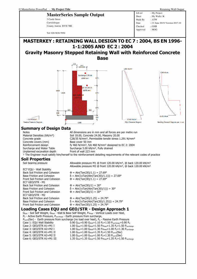
MASTERKEY : RETAINING WALL DESIGN TO EC 7 : 2004, BS EN 1996-1-1:2005 AND EC 2 : 2004
Gravity Masonry Stepped Retaining Wall with Reinforced Concrete Base
Summary of Design Data Notes All dimensions are in mm and all forces are per metre run Material Densities (kN/m³) Soil 18.00, Concrete 24.00, Masonry 20.00 Concrete grade C28/35 N/mm², Permissible tensile stress 1.291 N/mm² Concrete covers (mm) Base cover 50 mm Reinforcement design fy 460 N/mm², fyb 460 N/mm² designed to EC 2: 2004 Surcharge and Water Table Surcharge 5.00 kN/m², Fully drained Unplanned excavation depth Front of wall 223 mm † The Engineer must satisfy him/herself to the reinforcement detailing requirements of the relevant codes of practice
Soil Properties Soil bearing pressure Allowable pressure M1 @ front 120.00 kN/m², @ back 120.00 kN/m² Allowable pressure M2 @ front 120.00 kN/m², @ back 120.00 kN/m² EC7 EQU - Wall Stability Back Soil Friction and Cohesion Φ = Atn(Tan(30)/1.1) = 27.69° Base Friction and Cohesion δ = Atn(1xTan(Atn(Tan(30)/1.1))) = 27.69° Front Soil Friction and Cohesion Φ = Atn(Tan(30)/1.1) = 27.69° EC7 GEO/STR - M1 Back Soil Friction and Cohesion Φ = Atn(Tan(30)/1) = 30° Base Friction and Cohesion δ = Atn(1xTan(Atn(Tan(30)/1))) = 30° Front Soil Friction and Cohesion Φ = Atn(Tan(30)/1) = 30° EC7 GEO/STR - M2 Back Soil Friction and Cohesion Φ = Atn(Tan(30)/1.25) = 24.79° Base Friction and Cohesion δ = Atn(1xTan(Atn(Tan(30)/1.25))) = 24.79° Front Soil Friction and Cohesion Φ = Atn(Tan(30)/1.25) = 24.79°
Loading Cases EQU and GEO/STR - Design Approach 1 GSoil - Soil Self Weight, GWall - Wall & Base Self Weight, FvHeel - Vertical Loads over Heel, Pa - Active Earth Pressure, Psurcharge - Earth pressure from surcharge, Psurch(fav) - Earth pressure from surcharge (no load over heel), Pp - Passive Earth Pressure Case 1: EQU Wall Stability 0.90 GSoil+0.90 GWall+1.10 Pa+1.50 Psurcharge+0.90 Pp Case 2: GEO/STR A1+M1 I 1.00 GSoil+1.00 GWall+1.50 FvHeel+1.35 Pa+1.50 Psurcharge Case 3: GEO/STR A2+M2 I 1.00 GSoil+1.00 GWall+1.30 FvHeel+1.00 Pa+1.30 Psurcharge Case 4: GEO/STR A1+M1 II 1.00 GSoil+1.00 GWall+1.35 Pa+1.50 Psurch(fav) Case 5: GEO/STR A2+M2 II 1.00 GSoil+1.00 GWall+1.00 Pa+1.30 Psurch(fav) Case 6: GEO/STR A1+M1 III 1.35 GSoil+1.35 GWall+1.50 FvHeel+1.35 Pa+1.50 Psurcharge

© MasterSeries PowerPad - My Project Title Retaining Wall Output
MasterSeries Sample Output 3 Castle Street
Carrickfergus
County Antrim BT38 7BE
Job ref : My Project
Sheet : My Walls / 5
Made By : ATW
Date : 21 June 2015/ Version 2017.10
Checked : GHB
Approved : MOG Tel: 028 9036 5950
Geotechnical Design Wall Stability - Virtual Back Pressure
EQU Case 1 Overturning/Stabilising 16.861/29.122 0.579 OK
Wall Sliding - Virtual Back Pressure Case 2 Fx/(RxFriction + RxPassive) 21.294/(26.142+0.855) 0.789 OK Case 3 Fx/(RxFriction + RxPassive) 20.479/(20.775+0.697) 0.954 OK Case 4 Fx/(RxFriction + RxPassive) 21.294/(24.843+0.855) 0.829 OK Case 5 Fx/(RxFriction + RxPassive) 20.479/(19.875+0.697) 0.995 OK Case 6 Fx/(RxFriction + RxPassive) 21.294/(34.838+0.855) 0.597 OK
Soil Pressure Case 2 - Virtual Back 59.006/120 kN/m², Length under pressure 0.767 m 0.492 OK Case 3 - Virtual Back 57.828/120 kN/m², Length under pressure 0.778 m 0.482 OK Case 4 - Virtual Back 62.278/120 kN/m², Length under pressure 0.691 m 0.519 OK Case 5 - Virtual Back 60.433/120 kN/m², Length under pressure 0.712 m 0.504 OK Case 6 - Virtual Back 63.430/120 kN/m², Length under pressure 0.951 m 0.529 OK Case 2 - Wall Back 73.428/120 kN/m², Length under pressure 0.617 m 0.612 OK Case 3 - Wall Back 69.461/120 kN/m², Length under pressure 0.648 m 0.579 OK Case 4 - Wall Back 80.835/120 kN/m², Length under pressure 0.532 m 0.674 OK Case 5 - Wall Back 74.722/120 kN/m², Length under pressure 0.576 m 0.623 OK Case 6 - Wall Back 71.990/120 kN/m², Length under pressure 0.838 m 0.600 OK
Structural Design Masonry Wall Details
Partial Safety Factor (γmc/γmf) Units Category II, Execution Control Class 2 3/2.7 Table NA.1 Material Clay bricks with water absorption less than 7% Units and Mortar Strength 20 N/mm², Mortar designation M12/(i) Compressive Strength (fk) Group 1, γ=20 kN/m³ 8.58 N/mm² Table NA.4
Wall Design (Inner Face Tension) Critical Section Critical @ 0 mm from base, Case 2 Section Properties @ Base t=665 mm, Area=6650 cm², Zb=73704 cm³ Flexural Strength fxk1 fxk1=0.7, gd=0.027 N/mm², fxk1=fxk1+0.9 gd.γmf 0.765 N/mm² Table NA.6 Mr=fxk1.Zb/γmf 0.765x73704/2.7 20.89 kN.m Moment Capacity Check (M/Mr) M 16.3 kN.m, Mr 20.9 kN.m 0.781 OK Shear Capacity Check F 21.6 kN, fvk 0.311 N/mm², Fvr 82.7 kN 0.26 OK
Base Top Steel Design - Case 6 Steel Provided (Cover) Main B16@200 (50 mm) Dist. B16@200 (66 mm) 1005 mm² OK Compression Steel Provided (Cover) Main B16@200 (50 mm) Dist. B16@200 (66 mm) 1005 mm² Leverarm z=fn(d,b,As,fy,Fck) 142 mm, 1000 mm, 1005 mm², 460 N/mm², 28 N/mm² 129 mm Mr=fn(above,As',d',x,x/d) 1005 mm², 58 mm, 32 mm, 0.22 52.0 kN.m Moment Capacity Check (M/Mr) M 2.8 kN.m, Mr 52.0 kN.m 0.055 OK Shear Capacity Check F 18.9 kN, vc 0.650 N/mm², Fvr 92.2 kN 0.21 OK
Base Bottom Steel Design - Case 4 Steel Provided (Cover) Main B16@200 (50 mm) Dist. B16@200 (66 mm) 1005 mm² OK Compression Steel Provided (Cover) Main B16@200 (50 mm) Dist. B16@200 (66 mm) 1005 mm² Leverarm z=fn(d,b,As,fy,Fck) 142 mm, 1000 mm, 1005 mm², 460 N/mm², 28 N/mm² 129 mm Mr=fn(above,As',d',x,x/d) 1005 mm², 58 mm, 32 mm, 0.22 52.0 kN.m Moment Capacity Check (M/Mr) M 3.4 kN.m, Mr 52.0 kN.m 0.066 OK Shear Capacity Check F 22.8 kN, vc 0.650 N/mm², Fvr 92.2 kN 0.25 OK
© MasterSeries PowerPad - My Project Title Retaining Wall Output
MasterSeries Sample Output 3 Castle Street
Carrickfergus
County Antrim BT38 7BE
Job ref : My Project
Sheet : My Walls / 6
Made By : ATW
Date : 21 June 2015/ Version 2017.10
Checked : GHB
Approved : MOG Tel: 028 9036 5950
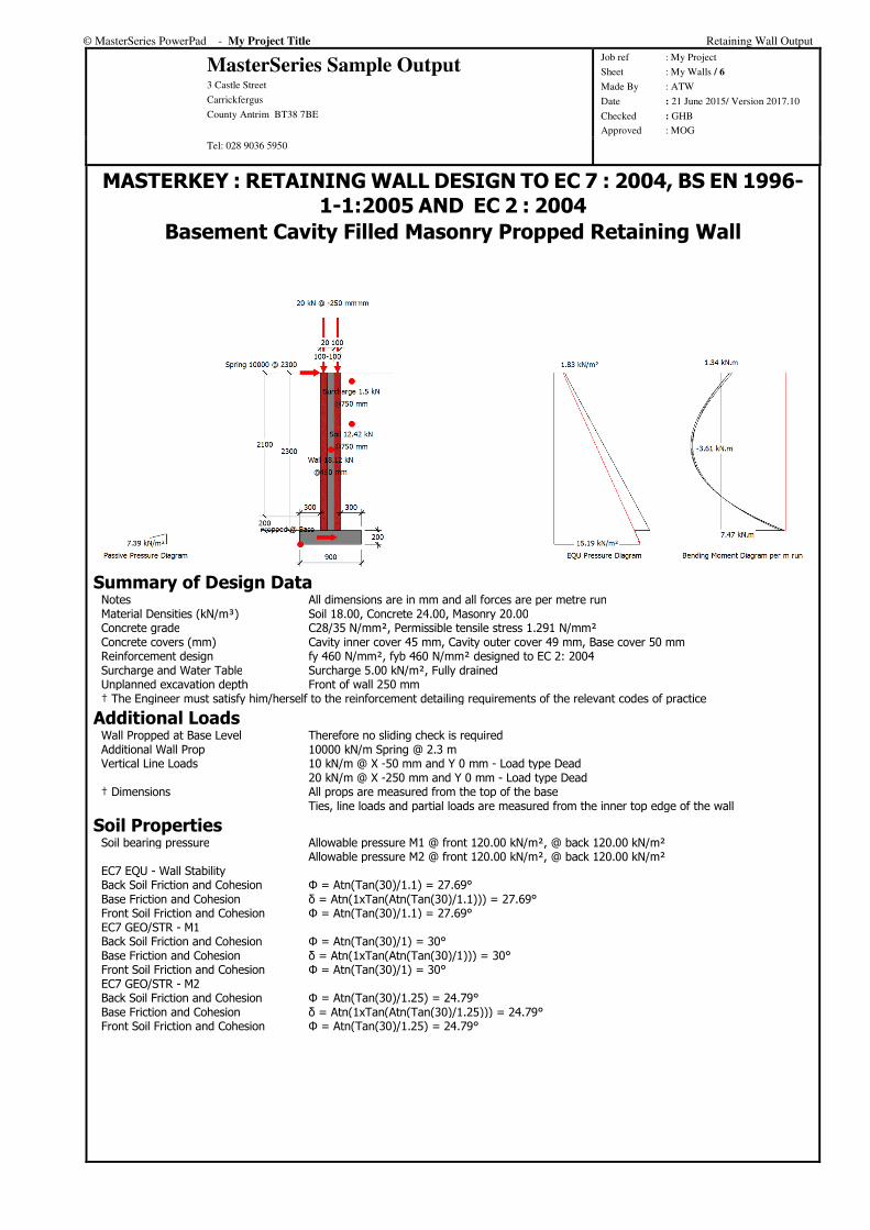
MASTERKEY : RETAINING WALL DESIGN TO EC 7 : 2004, BS EN 1996-1-1:2005 AND EC 2 : 2004
Basement Cavity Filled Masonry Propped Retaining Wall
Summary of Design Data Notes All dimensions are in mm and all forces are per metre run Material Densities (kN/m³) Soil 18.00, Concrete 24.00, Masonry 20.00 Concrete grade C28/35 N/mm², Permissible tensile stress 1.291 N/mm² Concrete covers (mm) Cavity inner cover 45 mm, Cavity outer cover 49 mm, Base cover 50 mm Reinforcement design fy 460 N/mm², fyb 460 N/mm² designed to EC 2: 2004 Surcharge and Water Table Surcharge 5.00 kN/m², Fully drained Unplanned excavation depth Front of wall 250 mm † The Engineer must satisfy him/herself to the reinforcement detailing requirements of the relevant codes of practice
Additional Loads Wall Propped at Base Level Therefore no sliding check is required Additional Wall Prop 10000 kN/m Spring @ 2.3 m Vertical Line Loads 10 kN/m @ X -50 mm and Y 0 mm - Load type Dead 20 kN/m @ X -250 mm and Y 0 mm - Load type Dead † Dimensions All props are measured from the top of the base Ties, line loads and partial loads are measured from the inner top edge of the wall
Soil Properties Soil bearing pressure Allowable pressure M1 @ front 120.00 kN/m², @ back 120.00 kN/m² Allowable pressure M2 @ front 120.00 kN/m², @ back 120.00 kN/m² EC7 EQU - Wall Stability Back Soil Friction and Cohesion Φ = Atn(Tan(30)/1.1) = 27.69° Base Friction and Cohesion δ = Atn(1xTan(Atn(Tan(30)/1.1))) = 27.69° Front Soil Friction and Cohesion Φ = Atn(Tan(30)/1.1) = 27.69° EC7 GEO/STR - M1 Back Soil Friction and Cohesion Φ = Atn(Tan(30)/1) = 30° Base Friction and Cohesion δ = Atn(1xTan(Atn(Tan(30)/1))) = 30° Front Soil Friction and Cohesion Φ = Atn(Tan(30)/1) = 30° EC7 GEO/STR - M2 Back Soil Friction and Cohesion Φ = Atn(Tan(30)/1.25) = 24.79° Base Friction and Cohesion δ = Atn(1xTan(Atn(Tan(30)/1.25))) = 24.79° Front Soil Friction and Cohesion Φ = Atn(Tan(30)/1.25) = 24.79°
© MasterSeries PowerPad - My Project Title Retaining Wall Output
MasterSeries Sample Output 3 Castle Street
Carrickfergus
County Antrim BT38 7BE
Job ref : My Project
Sheet : My Walls / 7
Made By : ATW
Date : 21 June 2015/ Version 2017.10
Checked : GHB
Approved : MOG Tel: 028 9036 5950
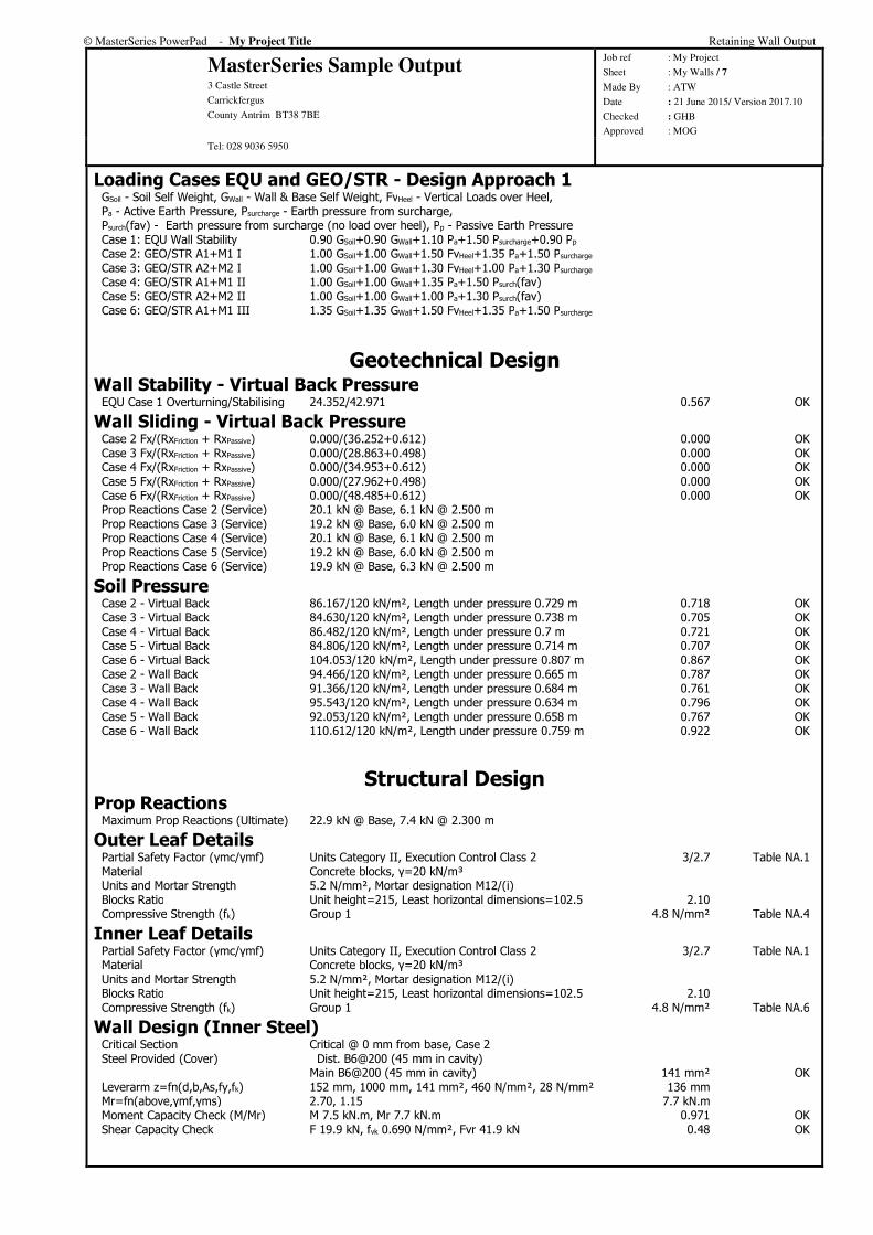
Loading Cases EQU and GEO/STR - Design Approach 1 GSoil - Soil Self Weight, GWall - Wall & Base Self Weight, FvHeel - Vertical Loads over Heel, Pa - Active Earth Pressure, Psurcharge - Earth pressure from surcharge, Psurch(fav) - Earth pressure from surcharge (no load over heel), Pp - Passive Earth Pressure Case 1: EQU Wall Stability 0.90 GSoil+0.90 GWall+1.10 Pa+1.50 Psurcharge+0.90 Pp Case 2: GEO/STR A1+M1 I 1.00 GSoil+1.00 GWall+1.50 FvHeel+1.35 Pa+1.50 Psurcharge Case 3: GEO/STR A2+M2 I 1.00 GSoil+1.00 GWall+1.30 FvHeel+1.00 Pa+1.30 Psurcharge Case 4: GEO/STR A1+M1 II 1.00 GSoil+1.00 GWall+1.35 Pa+1.50 Psurch(fav) Case 5: GEO/STR A2+M2 II 1.00 GSoil+1.00 GWall+1.00 Pa+1.30 Psurch(fav) Case 6: GEO/STR A1+M1 III 1.35 GSoil+1.35 GWall+1.50 FvHeel+1.35 Pa+1.50 Psurcharge
Geotechnical Design Wall Stability - Virtual Back Pressure
EQU Case 1 Overturning/Stabilising 24.352/42.971 0.567 OK
Wall Sliding - Virtual Back Pressure Case 2 Fx/(RxFriction + RxPassive) 0.000/(36.252+0.612) 0.000 OK Case 3 Fx/(RxFriction + RxPassive) 0.000/(28.863+0.498) 0.000 OK Case 4 Fx/(RxFriction + RxPassive) 0.000/(34.953+0.612) 0.000 OK Case 5 Fx/(RxFriction + RxPassive) 0.000/(27.962+0.498) 0.000 OK Case 6 Fx/(RxFriction + RxPassive) 0.000/(48.485+0.612) 0.000 OK Prop Reactions Case 2 (Service) 20.1 kN @ Base, 6.1 kN @ 2.500 m Prop Reactions Case 3 (Service) 19.2 kN @ Base, 6.0 kN @ 2.500 m Prop Reactions Case 4 (Service) 20.1 kN @ Base, 6.1 kN @ 2.500 m Prop Reactions Case 5 (Service) 19.2 kN @ Base, 6.0 kN @ 2.500 m Prop Reactions Case 6 (Service) 19.9 kN @ Base, 6.3 kN @ 2.500 m
Soil Pressure Case 2 - Virtual Back 86.167/120 kN/m², Length under pressure 0.729 m 0.718 OK Case 3 - Virtual Back 84.630/120 kN/m², Length under pressure 0.738 m 0.705 OK Case 4 - Virtual Back 86.482/120 kN/m², Length under pressure 0.7 m 0.721 OK Case 5 - Virtual Back 84.806/120 kN/m², Length under pressure 0.714 m 0.707 OK Case 6 - Virtual Back 104.053/120 kN/m², Length under pressure 0.807 m 0.867 OK Case 2 - Wall Back 94.466/120 kN/m², Length under pressure 0.665 m 0.787 OK Case 3 - Wall Back 91.366/120 kN/m², Length under pressure 0.684 m 0.761 OK Case 4 - Wall Back 95.543/120 kN/m², Length under pressure 0.634 m 0.796 OK Case 5 - Wall Back 92.053/120 kN/m², Length under pressure 0.658 m 0.767 OK Case 6 - Wall Back 110.612/120 kN/m², Length under pressure 0.759 m 0.922 OK
Structural Design Prop Reactions
Maximum Prop Reactions (Ultimate) 22.9 kN @ Base, 7.4 kN @ 2.300 m
Outer Leaf Details Partial Safety Factor (γmc/γmf) Units Category II, Execution Control Class 2 3/2.7 Table NA.1 Material Concrete blocks, γ=20 kN/m³ Units and Mortar Strength 5.2 N/mm², Mortar designation M12/(i) Blocks Ratio Unit height=215, Least horizontal dimensions=102.5 2.10 Compressive Strength (fk) Group 1 4.8 N/mm² Table NA.4
Inner Leaf Details Partial Safety Factor (γmc/γmf) Units Category II, Execution Control Class 2 3/2.7 Table NA.1 Material Concrete blocks, γ=20 kN/m³ Units and Mortar Strength 5.2 N/mm², Mortar designation M12/(i) Blocks Ratio Unit height=215, Least horizontal dimensions=102.5 2.10 Compressive Strength (fk) Group 1 4.8 N/mm² Table NA.6
Wall Design (Inner Steel) Critical Section Critical @ 0 mm from base, Case 2 Steel Provided (Cover) Dist. B6@200 (45 mm in cavity) Main B6@200 (45 mm in cavity) 141 mm² OK Leverarm z=fn(d,b,As,fy,fk) 152 mm, 1000 mm, 141 mm², 460 N/mm², 28 N/mm² 136 mm Mr=fn(above,γmf,γms) 2.70, 1.15 7.7 kN.m Moment Capacity Check (M/Mr) M 7.5 kN.m, Mr 7.7 kN.m 0.971 OK Shear Capacity Check F 19.9 kN, fvk 0.690 N/mm², Fvr 41.9 kN 0.48 OK

© MasterSeries PowerPad - My Project Title Retaining Wall Output
MasterSeries Sample Output 3 Castle Street
Carrickfergus
County Antrim BT38 7BE
Job ref : My Project
Sheet : My Walls / 8
Made By : ATW
Date : 21 June 2015/ Version 2017.10
Checked : GHB
Approved : MOG Tel: 028 9036 5950
Wall Design (Outer Steel) Critical Section Critical @ 1258 mm from base, Case 2 Steel Provided (Cover) Dist. B6@200 (45 mm in cavity) Main B6@200 (45 mm in cavity) 141 mm² OK Leverarm z=fn(d,b,As,fy,fk) 148 mm, 1000 mm, 141 mm², 460 N/mm², 28 N/mm² 132 mm Mr=fn(above,γmf,γms) 2.70, 1.15 7.5 kN.m Moment Capacity Check (M/Mr) M 3.6 kN.m, Mr 7.5 kN.m 0.484 OK Shear Capacity Check F 0.2 kN, fvk 0.367 N/mm², Fvr 21.7 kN 0.01 OK
Base Top Steel Design - Case 0 Steel Provided (Cover) Main B16@200 (50 mm) Dist. B16@200 (66 mm) 1005 mm² OK Compression Steel Provided (Cover) Main B16@200 (50 mm) Dist. B16@200 (66 mm) 1005 mm² Leverarm z=fn(d,b,As,fy,Fck) 142 mm, 1000 mm, 1005 mm², 460 N/mm², 28 N/mm² 129 mm Mr=fn(above,As',d',x,x/d) 1005 mm², 58 mm, 32 mm, 0.22 52.0 kN.m Moment Capacity Check (M/Mr) M 0.0 kN.m, Mr 52.0 kN.m 0.000 OK Shear Capacity Check F 0.0 kN, vc 0.650 N/mm², Fvr 92.2 kN 0.00 OK
Base Bottom Steel Design - Case 6 Steel Provided (Cover) Main B16@200 (50 mm) Dist. B16@200 (66 mm) 1005 mm² OK Compression Steel Provided (Cover) Main B16@200 (50 mm) Dist. B16@200 (66 mm) 1005 mm² Leverarm z=fn(d,b,As,fy,Fck) 142 mm, 1000 mm, 1005 mm², 460 N/mm², 28 N/mm² 129 mm Mr=fn(above,As',d',x,x/d) 1005 mm², 58 mm, 32 mm, 0.22 52.0 kN.m Moment Capacity Check (M/Mr) M 9.8 kN.m, Mr 52.0 kN.m 0.189 OK Shear Capacity Check F 37.5 kN, vc 0.650 N/mm², Fvr 92.2 kN 0.41 OK
© MasterSeries PowerPad - My Project Title Retaining Wall Output
MasterSeries Sample Output 3 Castle Street
Carrickfergus
County Antrim BT38 7BE
Job ref : My Project
Sheet : My Walls / 9
Made By : ATW
Date : 21 June 2015/ Version 2017.10
Checked : GHB
Approved : MOG Tel: 028 9036 5950
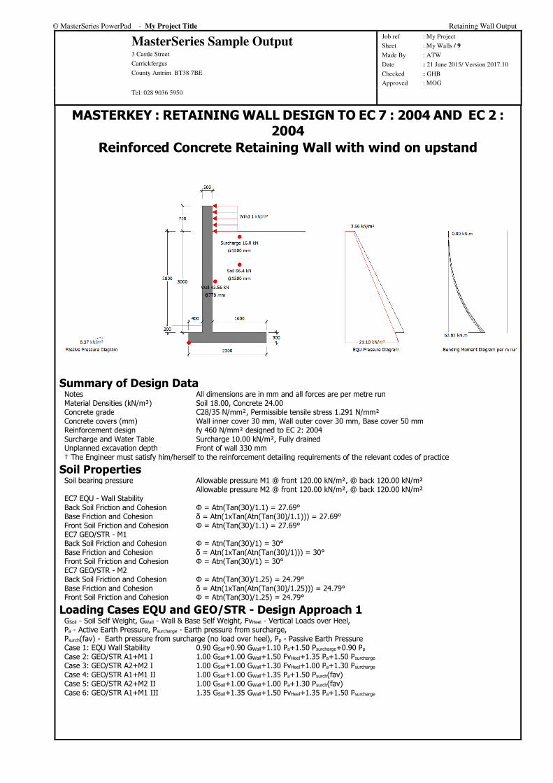
MASTERKEY : RETAINING WALL DESIGN TO EC 7 : 2004 AND EC 2 : 2004
Reinforced Concrete Retaining Wall with wind on upstand
Summary of Design Data Notes All dimensions are in mm and all forces are per metre run Material Densities (kN/m³) Soil 18.00, Concrete 24.00 Concrete grade C28/35 N/mm², Permissible tensile stress 1.291 N/mm² Concrete covers (mm) Wall inner cover 30 mm, Wall outer cover 30 mm, Base cover 50 mm Reinforcement design fy 460 N/mm² designed to EC 2: 2004 Surcharge and Water Table Surcharge 10.00 kN/m², Fully drained Unplanned excavation depth Front of wall 330 mm † The Engineer must satisfy him/herself to the reinforcement detailing requirements of the relevant codes of practice
Soil Properties Soil bearing pressure Allowable pressure M1 @ front 120.00 kN/m², @ back 120.00 kN/m² Allowable pressure M2 @ front 120.00 kN/m², @ back 120.00 kN/m² EC7 EQU - Wall Stability Back Soil Friction and Cohesion Φ = Atn(Tan(30)/1.1) = 27.69° Base Friction and Cohesion δ = Atn(1xTan(Atn(Tan(30)/1.1))) = 27.69° Front Soil Friction and Cohesion Φ = Atn(Tan(30)/1.1) = 27.69° EC7 GEO/STR - M1 Back Soil Friction and Cohesion Φ = Atn(Tan(30)/1) = 30° Base Friction and Cohesion δ = Atn(1xTan(Atn(Tan(30)/1))) = 30° Front Soil Friction and Cohesion Φ = Atn(Tan(30)/1) = 30° EC7 GEO/STR - M2 Back Soil Friction and Cohesion Φ = Atn(Tan(30)/1.25) = 24.79° Base Friction and Cohesion δ = Atn(1xTan(Atn(Tan(30)/1.25))) = 24.79° Front Soil Friction and Cohesion Φ = Atn(Tan(30)/1.25) = 24.79°
Loading Cases EQU and GEO/STR - Design Approach 1 GSoil - Soil Self Weight, GWall - Wall & Base Self Weight, FvHeel - Vertical Loads over Heel, Pa - Active Earth Pressure, Psurcharge - Earth pressure from surcharge, Psurch(fav) - Earth pressure from surcharge (no load over heel), Pp - Passive Earth Pressure Case 1: EQU Wall Stability 0.90 GSoil+0.90 GWall+1.10 Pa+1.50 Psurcharge+0.90 Pp Case 2: GEO/STR A1+M1 I 1.00 GSoil+1.00 GWall+1.50 FvHeel+1.35 Pa+1.50 Psurcharge Case 3: GEO/STR A2+M2 I 1.00 GSoil+1.00 GWall+1.30 FvHeel+1.00 Pa+1.30 Psurcharge Case 4: GEO/STR A1+M1 II 1.00 GSoil+1.00 GWall+1.35 Pa+1.50 Psurch(fav) Case 5: GEO/STR A2+M2 II 1.00 GSoil+1.00 GWall+1.00 Pa+1.30 Psurch(fav) Case 6: GEO/STR A1+M1 III 1.35 GSoil+1.35 GWall+1.50 FvHeel+1.35 Pa+1.50 Psurcharge

© MasterSeries PowerPad - My Project Title Retaining Wall Output
MasterSeries Sample Output 3 Castle Street
Carrickfergus
County Antrim BT38 7BE
Job ref : My Project
Sheet : My Walls / 10
Made By : ATW
Date : 21 June 2015/ Version 2017.10
Checked : GHB
Approved : MOG Tel: 028 9036 5950
Geotechnical Design Wall Stability - Virtual Back Pressure
EQU Case 1 Overturning/Stabilising 65.563/147.141 0.446 OK
Wall Sliding - Virtual Back Pressure Case 2 Fx/(RxFriction + RxPassive) 51.478/(88.889+0.785) 0.574 OK Case 3 Fx/(RxFriction + RxPassive) 49.859/(69.633+0.639) 0.710 OK Case 4 Fx/(RxFriction + RxPassive) 51.478/(75.032+0.785) 0.679 OK Case 5 Fx/(RxFriction + RxPassive) 49.859/(60.026+0.639) 0.822 OK Case 6 Fx/(RxFriction + RxPassive) 51.478/(115.150+0.785) 0.444 OK
Soil Pressure Case 2 - Virtual Back 89.546/120 kN/m², Length under pressure 1.719 m 0.746 OK Case 3 - Virtual Back 88.046/120 kN/m², Length under pressure 1.712 m 0.734 OK Case 4 - Virtual Back 87.643/120 kN/m², Length under pressure 1.483 m 0.730 OK Case 5 - Virtual Back 86.283/120 kN/m², Length under pressure 1.506 m 0.719 OK Case 6 - Virtual Back 104.914/120 kN/m², Length under pressure 1.901 m 0.874 OK Case 2 - Wall Back 98.900/120 kN/m², Length under pressure 1.557 m 0.824 OK Case 3 - Wall Back 96.131/120 kN/m², Length under pressure 1.568 m 0.801 OK Case 4 - Wall Back 95.995/120 kN/m², Length under pressure 1.354 m 0.800 OK Case 5 - Wall Back 93.210/120 kN/m², Length under pressure 1.394 m 0.777 OK Case 6 - Wall Back 112.332/120 kN/m², Length under pressure 1.776 m 0.936 OK
Structural Design Wall Design (Inner Steel)
Critical Section Critical @ 0 mm from base, Case 2 Steel Provided (Cover) Main B16@200 (30 mm) Dist. B16@200 (46 mm) 1005 mm² OK Compression Steel Provided (Cover) Main B10@200 (30 mm) Dist. B12@200 (40 mm) 393 mm² Leverarm z=fn(d,b,As,fy,Fck) 262 mm, 1000 mm, 1005 mm², 460 N/mm², 28 N/mm² 249 mm Mr=fn(above,As',d',x,x/d) 393 mm², 35 mm, 32 mm, 0.12 100.1 kN.m Moment Capacity Check (M/Mr) M 62.8 kN.m, Mr 100.1 kN.m 0.628 OK Shear Capacity Check F 52.5 kN, vc 0.496 N/mm², Fvr 130.0 kN 0.40 OK
Base Top Steel Design - Case 4 Steel Provided (Cover) Main B16@200 (50 mm) Dist. B16@200 (66 mm) 1005 mm² OK Compression Steel Provided (Cover) Main B16@200 (50 mm) Dist. B16@200 (66 mm) 1005 mm² Leverarm z=fn(d,b,As,fy,Fck) 242 mm, 1000 mm, 1005 mm², 460 N/mm², 28 N/mm² 229 mm Mr=fn(above,As',d',x,x/d) 1005 mm², 58 mm, 32 mm, 0.13 92.2 kN.m Moment Capacity Check (M/Mr) M 57.8 kN.m, Mr 92.2 kN.m 0.627 OK Shear Capacity Check F 57.4 kN, vc 0.519 N/mm², Fvr 125.6 kN 0.46 OK
Base Bottom Steel Design - Case 2 Steel Provided (Cover) Main B16@200 (50 mm) Dist. B16@200 (66 mm) 1005 mm² OK Compression Steel Provided (Cover) Main B16@200 (50 mm) Dist. B16@200 (66 mm) 1005 mm² Leverarm z=fn(d,b,As,fy,Fck) 242 mm, 1000 mm, 1005 mm², 460 N/mm², 28 N/mm² 229 mm Mr=fn(above,As',d',x,x/d) 1005 mm², 58 mm, 32 mm, 0.13 92.2 kN.m Moment Capacity Check (M/Mr) M 29.1 kN.m, Mr 92.2 kN.m 0.315 OK Shear Capacity Check F 41.0 kN, vc 0.519 N/mm², Fvr 125.6 kN 0.33 OK
© MasterSeries PowerPad - My Project Title Retaining Wall Output
MasterSeries Sample Output 3 Castle Street
Carrickfergus
County Antrim BT38 7BE
Job ref : My Project
Sheet : My Walls / 11
Made By : ATW
Date : 21 June 2015/ Version 2017.10
Checked : GHB
Approved : MOG Tel: 028 9036 5950
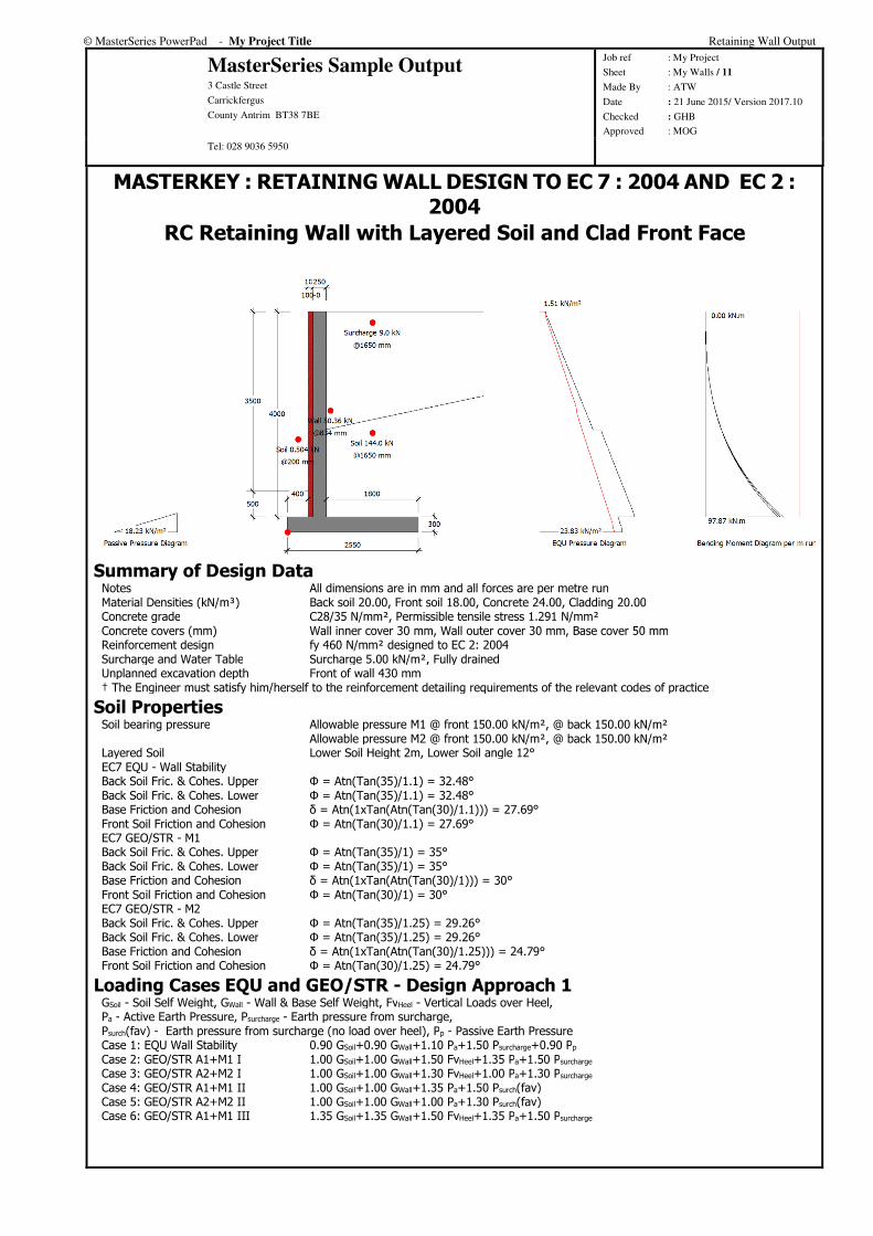
MASTERKEY : RETAINING WALL DESIGN TO EC 7 : 2004 AND EC 2 : 2004
RC Retaining Wall with Layered Soil and Clad Front Face
Summary of Design Data Notes All dimensions are in mm and all forces are per metre run Material Densities (kN/m³) Back soil 20.00, Front soil 18.00, Concrete 24.00, Cladding 20.00 Concrete grade C28/35 N/mm², Permissible tensile stress 1.291 N/mm² Concrete covers (mm) Wall inner cover 30 mm, Wall outer cover 30 mm, Base cover 50 mm Reinforcement design fy 460 N/mm² designed to EC 2: 2004 Surcharge and Water Table Surcharge 5.00 kN/m², Fully drained Unplanned excavation depth Front of wall 430 mm † The Engineer must satisfy him/herself to the reinforcement detailing requirements of the relevant codes of practice
Soil Properties Soil bearing pressure Allowable pressure M1 @ front 150.00 kN/m², @ back 150.00 kN/m² Allowable pressure M2 @ front 150.00 kN/m², @ back 150.00 kN/m² Layered Soil Lower Soil Height 2m, Lower Soil angle 12° EC7 EQU - Wall Stability Back Soil Fric. & Cohes. Upper Φ = Atn(Tan(35)/1.1) = 32.48° Back Soil Fric. & Cohes. Lower Φ = Atn(Tan(35)/1.1) = 32.48° Base Friction and Cohesion δ = Atn(1xTan(Atn(Tan(30)/1.1))) = 27.69° Front Soil Friction and Cohesion Φ = Atn(Tan(30)/1.1) = 27.69° EC7 GEO/STR - M1 Back Soil Fric. & Cohes. Upper Φ = Atn(Tan(35)/1) = 35° Back Soil Fric. & Cohes. Lower Φ = Atn(Tan(35)/1) = 35° Base Friction and Cohesion δ = Atn(1xTan(Atn(Tan(30)/1))) = 30° Front Soil Friction and Cohesion Φ = Atn(Tan(30)/1) = 30° EC7 GEO/STR - M2 Back Soil Fric. & Cohes. Upper Φ = Atn(Tan(35)/1.25) = 29.26° Back Soil Fric. & Cohes. Lower Φ = Atn(Tan(35)/1.25) = 29.26° Base Friction and Cohesion δ = Atn(1xTan(Atn(Tan(30)/1.25))) = 24.79° Front Soil Friction and Cohesion Φ = Atn(Tan(30)/1.25) = 24.79°
Loading Cases EQU and GEO/STR - Design Approach 1 GSoil - Soil Self Weight, GWall - Wall & Base Self Weight, FvHeel - Vertical Loads over Heel, Pa - Active Earth Pressure, Psurcharge - Earth pressure from surcharge, Psurch(fav) - Earth pressure from surcharge (no load over heel), Pp - Passive Earth Pressure Case 1: EQU Wall Stability 0.90 GSoil+0.90 GWall+1.10 Pa+1.50 Psurcharge+0.90 Pp Case 2: GEO/STR A1+M1 I 1.00 GSoil+1.00 GWall+1.50 FvHeel+1.35 Pa+1.50 Psurcharge Case 3: GEO/STR A2+M2 I 1.00 GSoil+1.00 GWall+1.30 FvHeel+1.00 Pa+1.30 Psurcharge Case 4: GEO/STR A1+M1 II 1.00 GSoil+1.00 GWall+1.35 Pa+1.50 Psurch(fav) Case 5: GEO/STR A2+M2 II 1.00 GSoil+1.00 GWall+1.00 Pa+1.30 Psurch(fav) Case 6: GEO/STR A1+M1 III 1.35 GSoil+1.35 GWall+1.50 FvHeel+1.35 Pa+1.50 Psurcharge
© MasterSeries PowerPad - My Project Title Retaining Wall Output
MasterSeries Sample Output 3 Castle Street
Carrickfergus
County Antrim BT38 7BE
Job ref : My Project
Sheet : My Walls / 12
Made By : ATW
Date : 21 June 2015/ Version 2017.10
Checked : GHB
Approved : MOG Tel: 028 9036 5950
Geotechnical Design Wall Stability - Virtual Back Pressure
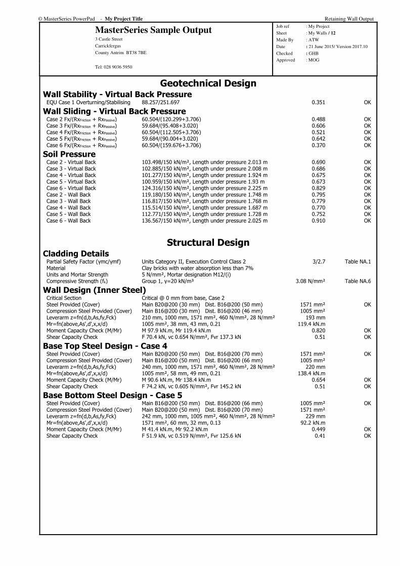
EQU Case 1 Overturning/Stabilising 88.257/251.697 0.351 OK
Wall Sliding - Virtual Back Pressure Case 2 Fx/(RxFriction + RxPassive) 60.504/(120.299+3.706) 0.488 OK Case 3 Fx/(RxFriction + RxPassive) 59.684/(95.408+3.020) 0.606 OK Case 4 Fx/(RxFriction + RxPassive) 60.504/(112.505+3.706) 0.521 OK Case 5 Fx/(RxFriction + RxPassive) 59.684/(90.004+3.020) 0.642 OK Case 6 Fx/(RxFriction + RxPassive) 60.504/(159.676+3.706) 0.370 OK
Soil Pressure Case 2 - Virtual Back 103.498/150 kN/m², Length under pressure 2.013 m 0.690 OK Case 3 - Virtual Back 102.885/150 kN/m², Length under pressure 2.008 m 0.686 OK Case 4 - Virtual Back 101.277/150 kN/m², Length under pressure 1.924 m 0.675 OK Case 5 - Virtual Back 100.959/150 kN/m², Length under pressure 1.93 m 0.673 OK Case 6 - Virtual Back 124.316/150 kN/m², Length under pressure 2.225 m 0.829 OK Case 2 - Wall Back 119.180/150 kN/m², Length under pressure 1.748 m 0.795 OK Case 3 - Wall Back 116.817/150 kN/m², Length under pressure 1.768 m 0.779 OK Case 4 - Wall Back 115.514/150 kN/m², Length under pressure 1.687 m 0.770 OK Case 5 - Wall Back 112.771/150 kN/m², Length under pressure 1.728 m 0.752 OK Case 6 - Wall Back 136.567/150 kN/m², Length under pressure 2.025 m 0.910 OK
Structural Design Cladding Details
Partial Safety Factor (γmc/γmf) Units Category II, Execution Control Class 2 3/2.7 Table NA.1 Material Clay bricks with water absorption less than 7% Units and Mortar Strength 5 N/mm², Mortar designation M12/(i) Compressive Strength (fk) Group 1, γ=20 kN/m³ 3.08 N/mm² Table NA.6
Wall Design (Inner Steel) Critical Section Critical @ 0 mm from base, Case 2 Steel Provided (Cover) Main B20@200 (30 mm) Dist. B16@200 (50 mm) 1571 mm² OK Compression Steel Provided (Cover) Main B16@200 (30 mm) Dist. B16@200 (46 mm) 1005 mm² Leverarm z=fn(d,b,As,fy,Fck) 210 mm, 1000 mm, 1571 mm², 460 N/mm², 28 N/mm² 193 mm Mr=fn(above,As',d',x,x/d) 1005 mm², 38 mm, 43 mm, 0.21 119.4 kN.m Moment Capacity Check (M/Mr) M 97.9 kN.m, Mr 119.4 kN.m 0.820 OK Shear Capacity Check F 70.4 kN, vc 0.654 N/mm², Fvr 137.3 kN 0.51 OK
Base Top Steel Design - Case 4 Steel Provided (Cover) Main B20@200 (50 mm) Dist. B16@200 (70 mm) 1571 mm² OK Compression Steel Provided (Cover) Main B16@200 (50 mm) Dist. B16@200 (66 mm) 1005 mm² Leverarm z=fn(d,b,As,fy,Fck) 240 mm, 1000 mm, 1571 mm², 460 N/mm², 28 N/mm² 220 mm Mr=fn(above,As',d',x,x/d) 1005 mm², 58 mm, 49 mm, 0.21 138.4 kN.m Moment Capacity Check (M/Mr) M 90.6 kN.m, Mr 138.4 kN.m 0.654 OK Shear Capacity Check F 74.2 kN, vc 0.605 N/mm², Fvr 145.2 kN 0.51 OK
Base Bottom Steel Design - Case 5 Steel Provided (Cover) Main B16@200 (50 mm) Dist. B16@200 (66 mm) 1005 mm² OK Compression Steel Provided (Cover) Main B20@200 (50 mm) Dist. B16@200 (70 mm) 1571 mm² Leverarm z=fn(d,b,As,fy,Fck) 242 mm, 1000 mm, 1005 mm², 460 N/mm², 28 N/mm² 229 mm Mr=fn(above,As',d',x,x/d) 1571 mm², 60 mm, 32 mm, 0.13 92.2 kN.m Moment Capacity Check (M/Mr) M 41.4 kN.m, Mr 92.2 kN.m 0.449 OK Shear Capacity Check F 51.9 kN, vc 0.519 N/mm², Fvr 125.6 kN 0.41 OK

© MasterSeries PowerPad - My Project Title Retaining Wall Output
MasterSeries Sample Output 3 Castle Street
Carrickfergus
County Antrim BT38 7BE
Job ref : My Project
Sheet : My Walls / 13
Made By : ATW
Date : 21 June 2015/ Version 2017.10
Checked : GHB
Approved : MOG Tel: 028 9036 5950
MASTERKEY : RETAINING WALL DESIGN TO BS 8002 AND BS 8110 :
1997
Reinforced Concrete Retaining Wall with Buttresses
Summary of Design Data Notes All dimensions are in mm and all forces are per metre run Material Densities (kN/m³) Soil 18.00, Concrete 24.00 Concrete grade fcu 35 N/mm², Permissible tensile stress 0.250 N/mm² Concrete covers (mm) Wall inner cover 30 mm, Wall outer cover 30 mm, Base cover 50 mm Reinforcement design fy 460 N/mm², fyv 460 N/mm² designed to BS 8110: 1997 Surcharge and Water Table Surcharge 5.00 kN/m², Fully drained Unplanned excavation depth Front of wall 330 mm † The Engineer must satisfy him/herself to the reinforcement detailing requirements of the relevant codes of practice
Counterfort Details Dimensions 440 mm wide spaced @ 3000 mm centre to centre Horizontally Spanning Wall Moment Coefficients : Positive Moment 0.1000, Negative Moment 0.1000
Soil Properties Soil bearing pressure Allowable pressure @ front 120.00 kN/m², @ back 120.00 kN/m² Back Soil Friction and Cohesion Φ = Atn(Tan(30)/1.2) = 25.69° Base Friction and Cohesion δ = Atn(0.75xTan(Atn(Tan(30)/1.2))) = 19.84° Front Soil Friction and Cohesion Φ = Atn(Tan(30)/1.2) = 25.69°
Loading Cases GSoil - Soil Self Weight, GWall - Wall & Base Self Weight, FvHeel - Vertical Loads over Heel, Pa - Active Earth Pressure, Psurcharge - Earth pressure from surcharge, Pp - Passive Earth Pressure Case 1: Geotechnical Design 1.00 GSoil+1.00 GWall+1.00 FvHeel+1.00 Pa+1.00 Psurcharge+1.00 Pp Case 2: Structural Ultimate Design 1.40 GSoil+1.40 GWall+1.60 FvHeel+1.00 Pa+1.00 Psurcharge+1.00 Pp
Geotechnical Design Wall Stability - Virtual Back Pressure
Case 1 Overturning/Stabilising 44.394/118.288 0.375 OK
Wall Sliding - Virtual Back Pressure Fx/(RxFriction + RxPassive) 37.554/(38.937+3.127) 0.893 OK
Soil Pressure Virtual Back (No uplift) Max(104.350/120, 9.233/120) kN/m² 0.870 OK Wall Back 118.642/120 kN/m², Length under pressure 1.819 m 0.989 OK

© MasterSeries PowerPad - My Project Title Retaining Wall Output
MasterSeries Sample Output 3 Castle Street
Carrickfergus
County Antrim BT38 7BE
Job ref : My Project
Sheet : My Walls / 14
Made By : ATW
Date : 21 June 2015/ Version 2017.10
Checked : GHB
Approved : MOG Tel: 028 9036 5950
Structural Design Pier Design (Inner Steel)
Critical Section Critical @ 0 mm from base, Case 2 Steel Provided (Cover) 3 No. B20 (40 mm) 942 mm² OK Compression Steel Provided (Cover) 3 No. B16 (40 mm) 603 mm² Effective Width (bef) hef=3.0 m, t=300, tp=1000, wp=440, ccp=3000 1640 mm Leverarm z=fn(d,b,As,fy,Fcu) 942 mm, 1640 mm, 942 mm², 460 N/mm², 35.0 N/mm² 895 mm Mr=fn(above,As',d',x,x/d) 603 mm², 56 mm, 67 mm, 0.07 367.7 kN.m Moment Capacity Check (M/Mr) M 122.9 kN.m, Mr 367.7 kN.m 0.334 OK Shear Reinforcement (Provided) 2 No. B8@250 mm c/c 101 mm² OK Fvr=fn(Asv,sv,vc,vcper,d,b) 101, 250, 0.431, 0.832, 942, 440 345.0 kN Shear Capacity Check F 113.4 kN, Fvr 345.0 kN 0.33 OK
Wall Design (Horizontal Inner Steel) Critical Section Critical @ 1 mm from base, Case 2, Pressure 23.20kN/m² Steel Provided (Cover) Main B16@200 (46 mm) Dist. B16@200 (30 mm) 1005 mm² OK Compression Steel Provided (Cover) Main B12@200 (40 mm) Dist. B10@200 (30 mm) 565 mm² Leverarm z=fn(d,b,As,fy,Fcu) 246 mm, 1000 mm, 1005 mm², 460 N/mm², 35.0
N/mm² 232 mm
Mr=fn(above,As',d',x,x/d) 565 mm², 46 mm, 31 mm, 0.13 101.9 kN.m Moment Capacity Check (M/Mr) M 20.9 kN.m, Mr 101.9 kN.m 0.205 OK Shear Capacity Check F 34.8 kN, vc 0.592 N/mm², Fvr 145.7 kN 0.24 OK
Wall Design (Horizontal Outer Steel) Critical Section Critical @ 1 mm from base, Case 2, Pressure 23.20kN/m² Steel Provided (Cover) Main B12@200 (40 mm) Dist. B10@200 (30 mm) 565 mm² OK Compression Steel Provided (Cover) Main B16@200 (46 mm) Dist. B16@200 (30 mm) 1005 mm² Leverarm z=fn(d,b,As,fy,Fcu) 254 mm, 1000 mm, 565 mm², 460 N/mm², 35.0 N/mm² 241 mm Mr=fn(above,As',d',x,x/d) 1005 mm², 54 mm, 18 mm, 0.07 59.6 kN.m Moment Capacity Check (M/Mr) M 20.9 kN.m, Mr 59.6 kN.m 0.350 OK Shear Capacity Check F 34.8 kN, vc 0.480 N/mm², Fvr 121.9 kN 0.29 OK
Base Top Steel Design Steel Provided (Cover) Main B16@200 (50 mm) Dist. B16@200 (66 mm) 1005 mm² OK Compression Steel Provided (Cover) Main B16@200 (50 mm) Dist. B16@200 (66 mm) 1005 mm² Leverarm z=fn(d,b,As,fy,Fcu) 242 mm, 1000 mm, 1005 mm², 460 N/mm², 35 N/mm² 228 mm Mr=fn(above,As',d',x,x/d) 1005 mm², 58 mm, 31 mm, 0.13 100.1 kN.m Moment Capacity Check (M/Mr) M 31.3 kN.m, Mr 100.1 kN.m 0.312 OK Shear Capacity Check F 40.4 kN, vc 0.598 N/mm², Fvr 144.8 kN 0.28 OK
Base Bottom Steel Design Steel Provided (Cover) Main B16@200 (50 mm) Dist. B16@200 (66 mm) 1005 mm² OK Compression Steel Provided (Cover) Main B16@200 (50 mm) Dist. B16@200 (66 mm) 1005 mm² Leverarm z=fn(d,b,As,fy,Fcu) 242 mm, 1000 mm, 1005 mm², 460 N/mm², 35 N/mm² 228 mm Mr=fn(above,As',d',x,x/d) 1005 mm², 58 mm, 31 mm, 0.13 100.1 kN.m Moment Capacity Check (M/Mr) M 8.9 kN.m, Mr 100.1 kN.m 0.089 OK Shear Capacity Check F 43.2 kN, vc 0.598 N/mm², Fvr 144.8 kN 0.30 OK
© MasterSeries PowerPad - My Project Title Retaining Wall Output
MasterSeries Sample Output 3 Castle Street
Carrickfergus
County Antrim BT38 7BE
Job ref : My Project
Sheet : My Walls / 15
Made By : ATW
Date : 21 June 2015/ Version 2017.10
Checked : GHB
Approved : MOG Tel: 028 9036 5950
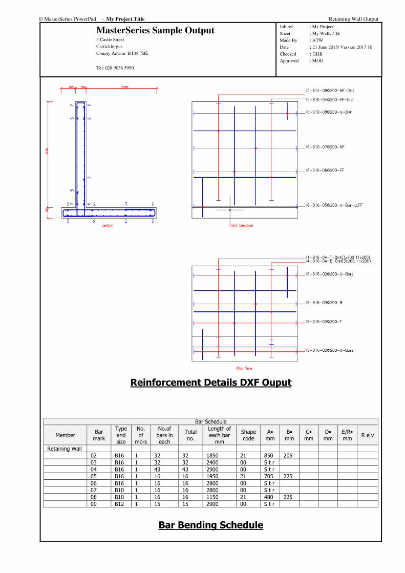
Reinforcement Details DXF Ouput
Bar Schedule
Member Bar
mark
Type and size
No. of
mbrs
No.of bars in each
Total no.
Length of each bar
mm
Shape code
A• mm
B• mm
C• mm
D• mm
E/R• mm
R e v
Retaining Wall
02 B16 1 32 32 1850 21 850 205
03 B16 1 32 32 2400 00 S t r
04 B16 1 43 43 2900 00 S t r
05 B16 1 16 16 1950 21 705 225
06 B16 1 16 16 2800 00 S t r
07 B10 1 16 16 2800 00 S t r
08 B10 1 16 16 1150 21 480 225
09 B12 1 15 15 2900 00 S t r
Bar Bending Schedule