Embed Size (px)
Citation preview

Master’s Thesis Effect of Diaphragm Discontinuity
Structural Engineering 1 AAU
ADDIS ABABA UNIVERSITYSCHOOL OF GRADUATE STUDIES
INSTITUTE OF TECHNOLOGY DEPARTMENTOF CIVIL ENGINEERING
Assessment of the Effect of Size of Diaphragm Discontinuity(Opening) on the Rigidity of Diaphragm and Distribution of
Lateral Load to the Lateral Load Resisting Element
A Thesis Submitted to the Graduate School of the Addis Ababa University inPartial Fulfillment of the Requirements for the Degree of Master of Science
in Civil Engineering (Structural Engineering)
By
KASSAHUN MEMRU
Advisor: ADIL ZEKARIA (Dr.-Ing)
July, 2013
ADDIS ABABA UNIVERSITYSCHOOL OF GRADUATE STUDIES
INSTITUTE OF TECHNOLOGYDEPARTMENT OF CIVIL ENGINEERING

Master’s Thesis Effect of Diaphragm Discontinuity
Structural Engineering 2 AAU
ADDIS ABABA UNIVERSITYSCHOOL OF GRADUATE STUDIES
INSTITUTE OF TECHNOLOGYDEPARTMENT OF CIVIL ENGINEERING
This is to certify that the thesis prepared by Kassahun Memru, entitled:
Assessment of the Effect of Size of Diaphragm Discontinuity (Opening) on
the Rigidity of Diaphragm and Distribution of Lateral Load to the Lateral
Load Resisting Element and submitted in partial fulfillment of the
requirements for the degree of Degree of Master of Science in Civil
Engineering (Structural Engineering) complies with the regulations of the
University and meets the accepted standards with respect to originality
and quality.
Signed by the Examining Committee:
Dr.-Ing Adil Zekaria _____________________ _____________________
Advisor Signature Date
Dr.- Esayas Gebreyohannes _____________________ _____________________
External Examiner Signature Date
Dr.-Ing Girma Zerayohannes _____________________ _____________________
Internal Examiner Signature Date
Dr.- Bikila Teklu _____________________ _____________________
Chairman Signature Date

Master’s Thesis Effect of Diaphragm Discontinuity
Structural Engineering iii AAU
ABSTRACT
Assessment of the Effect of Size of Diaphragm Discontinuity (Opening) on the
Rigidity of Diaphragm and Distribution of Lateral Load to the Lateral Load
Resisting Element
Kassahun Memru
Addis Ababa University, 2013
Earthquake - resistant structures are provided with lateral and vertical seismic force –
resisting systems capable of transmitting inertial forces from the location of masses
throughout the structure to the foundations. Floor and roof diaphragms play a key role in
distributing earthquake-induced loads to the lateral load resisting systems. Continuity and
regular transitions are essential requirements to achieve adequate load paths. Floor
diaphragm that has a large opening is likely to be inefficient in distributing seismic loads to
the vertical elements.
Design codes like UBC-97 specify that diaphragms having cut out or open areas greater than
50 percent of the gross enclosed area of the diaphragm are affected by diaphragm
discontinuity[11]. However, there are different cases where this provision can be
unsuccessful. In order to investigate the effect of diaphragm discontinuity on the response of
a structure, different parametric studies have been carried out. In the parametric studies,
story height, shear wall width, number of stories, number of bays, shape of diaphragm
opening, diaphragm opening size, span length and opening location in stories are taken as
parameters.
The study proceeded by assessing the effect of diaphragm discontinuity/opening on response
of a structure like diaphragm rigidity, story drift, distribution of lateral load to lateral force
resisting element and natural vibration period for each parametric study listed above. The
study has shown that the rigidity of a slab does not only depend on the opening size, but
rather depend on the stiffness of vertical elements, number of stories, aspect ratio of the slab
dimension and shape of diaphragm opening.

Master’s Thesis Effect of Diaphragm Discontinuity
Structural Engineering iv AAU
The investigation has shown that the code provision relating diaphragm rigidity to opening
size is not always satisfied.
Key words: diaphragm discontinuity, opening, diaphragm rigidity, actual diaphragm
stiffness, rigid diaphragm, flexible diaphragm, stiffness, story drift, lateral force distribution,
period

Master’s Thesis Effect of Diaphragm Discontinuity
Structural Engineering v AAU
ACKNOWLEDGEMENT
First and foremost, my utmost gratitude to the Almighty God, Who gave me the commitment
and tolerance to pass various obstacles and come up to the accomplishment of this thesis.
Next, I would like to express the deepest appreciation to Dr.-Ing Adil Zekaria, who
undertook to act as my advisor despite his many other academic and professional
commitments. His wisdom, knowledge and commitment to the highest standards inspired
and motivated me. I consider myself very fortunate for being able to work with a very
considerate and encouraging doctor like him. Without his offering to accomplish this
research, I would not be able to finish my study.
Besides, I would like to thank Ethiopian Road Authority (ERA) who sponsored me to have
this great opportunity.
I would like to express my deep gratitude to my parents Memru Mengesha and Zenebech
Hirbicho for their prayers and critical supports. I would like also to thank Architect
Wondimagegnehu Guta for his critical support and encouragement. I would like to thank
also all LYDA Consulting Architects and Engineers PLC staffs.
I gratefully thank my friends who have helped and supported me in many ways: Berhanu
Zemecha, Tsegaye Debelo, Meron Teshome and Tsedey Tadele.
Finally, I would like to put on record my gratitude and appreciation to all my instructors,
classmates and to all individuals who contributed directly or indirectly to this thesis and
provided the necessary materials and support; without their care and love this thesis would
not have been realized.

Master’s Thesis Effect of Diaphragm Discontinuity
Structural Engineering vi AAU
This work is dedicated to:
My Family
And
My Advisor Dr.-Ing. Adil Zekaria

Master’s Thesis Effect of Diaphragm Discontinuity
Structural Engineering vii AAU
Table of ContentsABSTRACT ............................................................................................................................. iii
ACKNOWLEDGEMENT ........................................................................................................ v
Table of Contents .................................................................................................................... vii
List of Figures ........................................................................................................................... x
List of Tables........................................................................................................................... xii
List of Symbols ...................................................................................................................... xiii
Chapter One............................................................................................................................. 1
1. Introduction........................................................................................................................ 1
1.1. Background................................................................................................................. 1
1.2. Statement of the problem............................................................................................ 1
1.3. Objectives ................................................................................................................... 2
1.4. Methodology............................................................................................................... 2
Chapter Two ............................................................................................................................ 3
2. Literature Review............................................................................................................... 3
2.1. Floor diaphragm ......................................................................................................... 3
2.2. Classification of diaphragm behavior......................................................................... 4
2.2.1. Rigid diaphragm...................................................................................................... 5
2.2.2. Flexible diaphragm ................................................................................................. 5
2.2.3. Stiff diaphragm ....................................................................................................... 6
2.3. Significant factors affecting diaphragm behavior ...................................................... 6
2.4. Opening in a diaphragm ........................................................................................... 10
2.4.1. Opening in two way concrete floor slab according to ACI-code.......................... 10
2.4.2. Diaphragm rigidity and opening size .................................................................... 13
2.4.3. Effects of opening (diaphragm discontinuity) ...................................................... 14
2.4.3.1. Diaphragm capacity........................................................................................... 14
2.4.3.2. Vertical load path .............................................................................................. 15

Master’s Thesis Effect of Diaphragm Discontinuity
Structural Engineering viii AAU
2.4.3.3. Story drift .......................................................................................................... 17
2.4.3.4. Diaphragm rigidity ............................................................................................ 17
2.4.3.5. Lateral force distribution ................................................................................... 18
2.4.3.6. Natural period of vibration ................................................................................ 19
2.5. Lateral force and lateral force resisting system ........................................................ 19
2.5.1. Lateral force .......................................................................................................... 19
2.5.2. Lateral force resisting system ............................................................................... 20
2.5.2.1. Vertical system.................................................................................................. 20
2.5.2.2. Typical lateral force resisting system................................................................ 21
2.6. Structural response characteristics............................................................................ 23
2.6.1. Stiffness................................................................................................................. 23
2.6.1.1. Factors influencing stiffness.............................................................................. 24
2.7. Method of analysis.................................................................................................... 25
2.7.1. Dynamic analysis .................................................................................................. 26
2.7.1.1. Modal and spectral analysis .............................................................................. 28
2.7.2. Static analysis........................................................................................................ 29
2.7.2.1. Equivalent static analysis .................................................................................. 30
2.7.2.2. Second order P-delta effects.............................................................................. 30
2.7.3. Elastic second-order analysis ................................................................................ 31
2.8. ETABS software....................................................................................................... 32
2.9. Finite element modeling ........................................................................................... 33
2.10. Damage related to diaphragm ............................................................................... 34
Chapter Three ....................................................................................................................... 36
3. Parametric Study.............................................................................................................. 36
3.1. General...................................................................................................................... 36
3.2. Description of the parametric study.......................................................................... 36
3.3. Modeling................................................................................................................... 37

Master’s Thesis Effect of Diaphragm Discontinuity
Structural Engineering ix AAU
3.3.1. Description of structures ....................................................................................... 37
3.3.2. Material properties ................................................................................................ 40
3.3.3. Vertical element system........................................................................................ 40
3.3.4. Loading ................................................................................................................. 40
3.4. Analysis .................................................................................................................... 41
3.5. Parametric studies of cases and discussions ............................................................. 41
3.5.1. Case – 1: Story height as a parameter ................................................................... 41
3.5.2. Case – 2: Shear wall width as a parameter............................................................ 45
3.5.3. Case – 3: Number of stories as a parameter.......................................................... 50
3.5.4. Case – 4: Number of bays as a parameter ............................................................. 55
3.5.5. Case – 5: Shape of opening as a parameter........................................................... 58
3.5.6. Case – 6: Size of opening as a parameter.............................................................. 60
3.5.7. Case – 7: Span length as a parameter.................................................................... 63
3.5.8. Case – 8: Opening location in stories as a parameter ........................................... 67
3.6. Summary of discussion............................................................................................. 72
Chapter Four ......................................................................................................................... 74
4. Conclusion and Recommendation ................................................................................... 74
4.1. Conclusion ................................................................................................................ 74
4.2. Recommendation ...................................................................................................... 76
4.3. Further research ........................................................................................................ 76
References: .............................................................................................................................. 77
APPENDICES ....................................................................................................................... 79
Appendix A: All the Structures Analyzed for Parametric Study ............................................ 79
Appendix B: Sample and Representative Drawings ............................................................... 83
Master’s Thesis Effect of Diaphragm Discontinuity
Structural Engineering x AAU
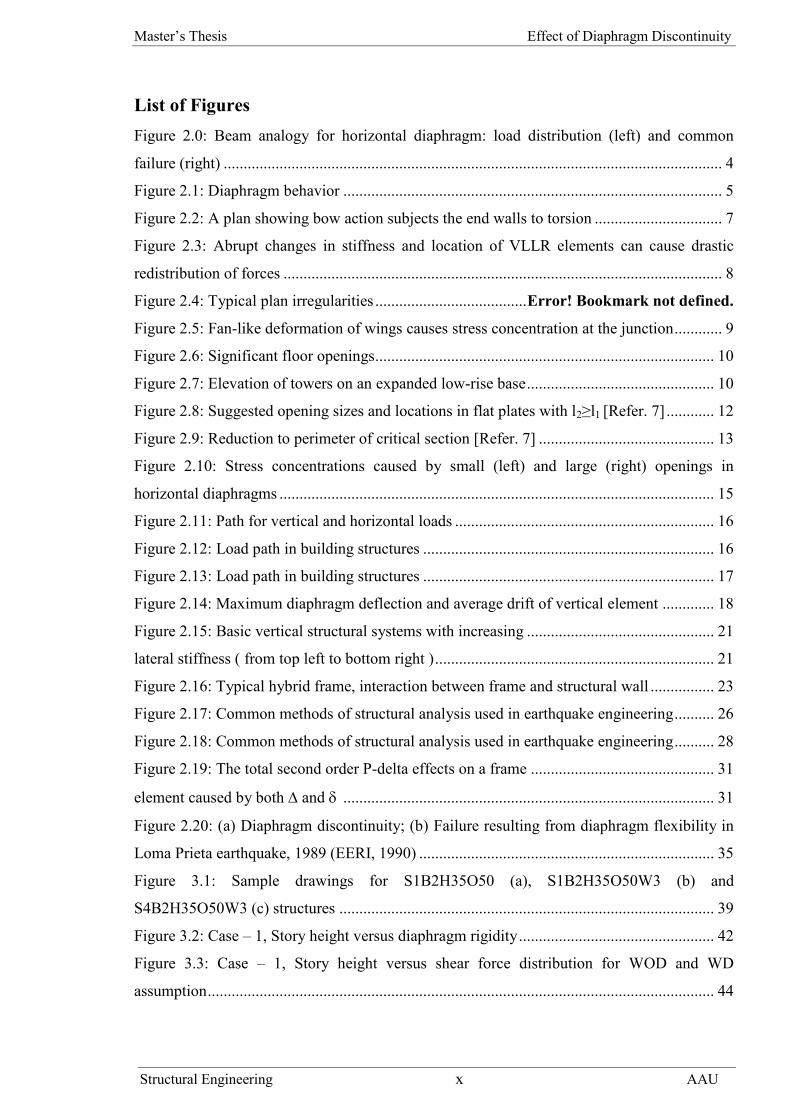
List of FiguresFigure 2.0: Beam analogy for horizontal diaphragm: load distribution (left) and common
failure (right) ............................................................................................................................. 4
Figure 2.1: Diaphragm behavior ............................................................................................... 5
Figure 2.2: A plan showing bow action subjects the end walls to torsion ................................ 7
Figure 2.3: Abrupt changes in stiffness and location of VLLR elements can cause drastic
redistribution of forces .............................................................................................................. 8
Figure 2.4: Typical plan irregularities ......................................Error! Bookmark not defined.
Figure 2.5: Fan-like deformation of wings causes stress concentration at the junction............ 9
Figure 2.6: Significant floor openings..................................................................................... 10
Figure 2.7: Elevation of towers on an expanded low-rise base............................................... 10
Figure 2.8: Suggested opening sizes and locations in flat plates with l2≥l1 [Refer. 7] ............ 12
Figure 2.9: Reduction to perimeter of critical section [Refer. 7] ............................................ 13
Figure 2.10: Stress concentrations caused by small (left) and large (right) openings in
horizontal diaphragms ............................................................................................................. 15
Figure 2.11: Path for vertical and horizontal loads ................................................................. 16
Figure 2.12: Load path in building structures ......................................................................... 16
Figure 2.13: Load path in building structures ......................................................................... 17
Figure 2.14: Maximum diaphragm deflection and average drift of vertical element ............. 18
Figure 2.15: Basic vertical structural systems with increasing ............................................... 21
lateral stiffness ( from top left to bottom right )...................................................................... 21
Figure 2.16: Typical hybrid frame, interaction between frame and structural wall ................ 23
Figure 2.17: Common methods of structural analysis used in earthquake engineering.......... 26
Figure 2.18: Common methods of structural analysis used in earthquake engineering.......... 28
Figure 2.19: The total second order P-delta effects on a frame .............................................. 31
element caused by both and ............................................................................................. 31
Figure 2.20: (a) Diaphragm discontinuity; (b) Failure resulting from diaphragm flexibility in
Loma Prieta earthquake, 1989 (EERI, 1990) .......................................................................... 35
Figure 3.1: Sample drawings for S1B2H35O50 (a), S1B2H35O50W3 (b) and
S4B2H35O50W3 (c) structures .............................................................................................. 39
Figure 3.2: Case – 1, Story height versus diaphragm rigidity................................................. 42
Figure 3.3: Case – 1, Story height versus shear force distribution for WOD and WD
assumption............................................................................................................................... 44

Master’s Thesis Effect of Diaphragm Discontinuity
Structural Engineering xi AAU
Figure 3.4: Case – 2, Shear wall width versus diaphragm rigidity ......................................... 46
Figure 3.5: Case – 2, Shear wall width versus shear force distribution for WOD and WD
assumption............................................................................................................................... 48
Figure 3.6: Case – 3, Number of stories versus diaphragm rigidity........................................ 51
Figure 3.7: Case – 3, Number of stories versus shear force distribution for WOD and WD
assumption............................................................................................................................... 53
Figure 3.8: Case – 4, Number of bays versus diaphragm rigidity........................................... 55
Figure 3.9: Case – 6, Size of opening versus diaphragm rigidity ........................................... 61
Figure 3.10: Case – 6, Size of opening versus shear force distribution for WOD and WD
assumption............................................................................................................................... 62
Figure 3.11: Case – 7, Span length versus diaphragm rigidity ............................................... 64
Figure 3.12: Case – 7, Span length versus shear force distribution for WOD and WD
assumption............................................................................................................................... 66
Figure 3.13: Case – 8, Number of stories versus diaphragm rigidity...................................... 68
Figure B1: Drawings for S1B1H35O50W2 ............................................................................ 83
Figure B2: Drawings for S1B2H35O50W1R ......................................................................... 83
Figure B3: Drawings for S1B2H35O50W1C ......................................................................... 84
Figure B4: Drawings for S1B2H35O50W1IR ........................................................................ 84
Figure B5: Drawings for S1B3H35O50W2 ............................................................................ 85

Master’s Thesis Effect of Diaphragm Discontinuity
Structural Engineering xii AAU
List of TablesTable 2.1: FEMA 273 diaphragm classification ..................................................................... 18
Table 2.2: Comparisons of requirements for static and dynamic analyses ............................. 25
Table 2.3: ACI recommendation of stiffness modifiers for elastic second-order analysis ..... 32
Table 3.1: Structures for parametric study .............................................................................. 37
Table 3.2: Lists of parameters in eight cases .......................................................................... 41
Table 3.3: Case – 1, Diaphragm rigidity summary for actual diaphragm stiffness................. 42
Table 3.4: Case – 1, Shear force distribution in column for WOD and WD assumption ....... 43
Table 3.5: Case – 2, Diaphragm rigidity summary for actual diaphragm stiffness................. 46
Table 3.6: Case – 2, Shear force distribution in column for WOD and WD assumption ....... 47
Table 3.7: Case – 3, Diaphragm rigidity summary for actual diaphragm stiffness................. 50
Table 3.8: Case – 3, Shear force distribution in column for WOD and WD assumption ....... 51
Table 3.9: Case – 4, Diaphragm rigidity summary for actual diaphragm stiffness................. 55
Table 3.10: Case – 4, Shear force distribution in column for WOD and WD assumption ..... 56
Table 3.11: Case – 5, Diaphragm rigidity summary for actual diaphragm stiffness............... 58
Table 3.12: Case – 5, Shear force distribution in column for WOD and WD assumption ..... 58
Table 3.13: Case – 6, Diaphragm rigidity summary for actual diaphragm stiffness............... 60
Table 3.14: Case – 6, Shear force distribution in column for WOD and WD assumption ..... 61
Table 3.15: Case – 7, Diaphragm rigidity summary for actual diaphragm stiffness............... 64
Table 3.16: Case – 7, Shear force distribution in column for WOD and WD assumption ..... 65
Table 3.17: Case – 8, Diaphragm rigidity summary for actual diaphragm stiffness............... 68
Table 3.18: Case – 8, Shear force distribution in column for WOD and WD assumption ..... 69
Table app1: A total of 123-structures analyzed for parametric study ..................................... 79

Master’s Thesis Effect of Diaphragm Discontinuity
Structural Engineering xiii AAU
List of Symbols
A Cross Sectional Area
a Nodal Displacement Vector
ACI American Concrete Institute
ATC Applied Technology Council
BFs Braced Frames
bo Critical Section
CBFs Concentrically Braced Frames
Comb Combination
DL Dead Load
E Elastic Young’s Modulus
EBCS Ethiopian Buildings Code Standard
EBFs Eccentrically Braced Frames
EC European Code
Ec Modulus of Elasticity of Concrete
EQ Earthquake
ETABS Extended 3D Analysis of Building Systems
f Force Vector
FD Damping Force Vector
FE Vector of Earthquake Loads
FEMA Federal Emergency Management Agency
FI Inertia Force Vector

Master’s Thesis Effect of Diaphragm Discontinuity
Structural Engineering xiv AAU
FR Vector of Restoring Forces
G Elastic Shear Modulus
HFs Hybrid Frames
H/L Height to Width
I Moment of Inertia
Ig Moment of Inertia of Gross Concrete Section
J Torsional Moment of Inertia
K Global Stiffness Matrix
kPa Kilo Pascal
LFRS Lateral Force Resisting System
LLRS Lateral Load Resisting System
LL Live Load
Lmax, Lmin Larger and Smaller in Plan Dimension of the Building Measured in
Orthogonal Directions
MDOF Multi Degree of Freedom
MRFs Moment Resisting Frames
Psf Pound Per Square Foot
P-Δ Forces Deformation
RC Reinforced Concrete
SDOF Single Degree of Freedom
SWs Structural Walls
T Period
TSs Tube Systems

Master’s Thesis Effect of Diaphragm Discontinuity
Structural Engineering xv AAU
UBC Uniform Building Code
VLFR Vertical Lateral Force Resisting
VLLR Vertical Lateral Load Resisting
WD With Diaphragm
WOD Without Diaphragm
(%) Difference in Percent
av Average Inter Story Drift
diaph In plane Diaphragm Displacement
drr Diaphragm Rigidity Ratio
story Inter Story Drift
δ Local Deformation
λ Ratio Between the Length of the Longer and the Length of the Smaller
Side in Plan

Master’s Thesis Effect of Diaphragm Discontinuity
Structural Engineering 1 AAU
Chapter One
1. Introduction
1.1. Background
Earthquake - resistant structures are provided with lateral and vertical seismic force –
resisting systems capable of transmitting inertial forces from the location of masses
throughout the structure to the foundations. Continuity and regular transitions are essential
requirements to achieve adequate load paths.
Floor and roof systems act as horizontal diaphragms in building structures. They collect and
transmit inertia forces to the vertical elements of lateral load resistant systems, i.e. columns
and structural walls. They also ensure that vertical components act together under gravity
and seismic loads. Diaphragm action is especially relevant in cases of complex and non -
uniform layouts of vertical structural systems, or where systems with different horizontal
deformation characteristics are used together (as in dual or mixed systems)[1].
Continuity between structural components is vital for the safe transfer of the seismic forces
to the ground. Failure of buildings during earthquakes is often due to the inability of their
parts to work together in resisting lateral forces. Floor diaphragms that have very elongated
plan shapes, or a large opening, are likely to be inefficient in distributing seismic loads to the
vertical elements. The assessment of the effect of diaphragm discontinuity on diaphragm
rigidity and distribution of lateral load to lateral force resisting element is the main objective
of this thesis.
1.2. Statement of the problem
Most of the time buildings or structures with floor plan have open down throughout the floor
or in some section of the floor like mezzanine floors in a building. The existence of these
openings has different architectural function or aesthetic value. When these openings are
usually large, most of the time effect of the size of opening (diaphragm discontinuity) which
affects rigidity of a diaphragm and distribution of lateral load to the lateral load resisting
element are not given serious attention.

Master’s Thesis Effect of Diaphragm Discontinuity
Structural Engineering 2 AAU
Design codes like UBC-97 specify that diaphragms having cut out or open areas greater than
50 percent of the gross enclosed area of the diaphragm, or changes in effective diaphragm
stiffness of more than 50 percent from one story to the next is affected by diaphragm
discontinuity[11]. In this thesis, the effect of the size of diaphragm discontinuity (opening) on
the diaphragm rigidity and lateral force distribution to is assessed.
1.3. Objectives
Floor diaphragms that have openings considerably weaken slab capacity and affect even
distribution of seismic loads to the vertical lateral load resisting elements. The effect is
governed by the rigidity of diaphragm and the size of openings. The objective of this thesis
is to assess how a size of opening affects diaphragm rigidity and distribution of lateral load
to the lateral load resisting elements.
1.4. Methodology
In order to assess the effects of diaphragm discontinuity (opening) on diaphragm rigidity and
distribution of later force to the vertical element, number of building structures are modeled,
analyzed and evaluated according to codes provision. To do this; software ETABS 9.7,
NEHRP guidelines (FEMA 273)[4] and other additional material have been used to enhance
and inspire the research, the materials used in this study are mentioned in the reference
section.

Master’s Thesis Effect of Diaphragm Discontinuity
Structural Engineering 3 AAU
Chapter Two
2. Literature Review
2.1. Floor diaphragm
The primary function of floor and roof systems is to support gravity loads and to transfer
these loads to other structural members such as columns and walls. Furthermore, they play a
central role in the distribution of wind and seismic forces to the vertical elements of the
lateral load resisting system (such as frames and structural walls).
In the earthquake resistant design of building structures, the building is designed and
detailed to act as a single unit under the action of seismic forces. Design of a building as a
single unit helps to increase the redundancy and the integrity of the building. The horizontal
forces generated by earthquake excitations are transferred to the ground by the vertical
systems of the building, which are designed for lateral load resistance (e.g. frames, bracing,
and walls). These vertical systems are generally tied together as a unit by means of the
building floors and roof. In this sense, the floor/roof structural systems, used primarily to
create enclosures and resist gravity (or out of plane) loads are also designed as horizontal
diaphragms to resist and to transfer horizontal (or in-plane) loads to the appropriate vertical
elements[3].
Diaphragms behave in-plane as horizontal continuous beams supported by vertical lateral
resisting systems (also referred to as ‘ beam analogy ’ ). The deck or slab is the web of the
beam carrying the shear and the perimeter spandrel or wall is the flange of the beam
resisting bending as shown in Figure 2.0. Diaphragms should possess adequate shear and
bending resistance to withstand in - plane seismic loads and out - of - plane gravity loads[1].
The various floor and roof systems that have evolved primarily for the purpose of supporting
gravity loads do not lend themselves easily to analytical calculation of in-plane stiffness of
the floor diaphragm. Therefore, in this thesis, the diaphragm rigidity (diaphragm in-plane
stiffness) is evaluated according to FEMA 273 classification, which is discussed in section
2.4.3.4.

Master’s Thesis Effect of Diaphragm Discontinuity
Structural Engineering 4 AAU
Figure 2.0: Beam analogy for horizontal diaphragm:
load distribution (left) and common failure (right)
2.2. Classification of diaphragm behavior
The distribution of horizontal forces by the horizontal diaphragm to the various vertical
lateral load resisting (VLLR) elements depend on the relative rigidity of the horizontal
diaphragm and the VLLR elements. According to FEMA 273, floor diaphragms shall be
classified as rigid, stiff and flexible[1,3,4].

Master’s Thesis Effect of Diaphragm Discontinuity
Structural Engineering 5 AAU
Figure 2.1: Diaphragm behavior
(a) Loading and building proportions. (b) Rigid diaphragm behavior.
(c) Flexible diaphragm behavior, (d) Semi rigid diaphragm behavior
2.2.1. Rigid diaphragm
Diaphragms shall be considered as rigid when the maximum lateral deformation of the
diaphragm is less than half the average inter-story drift of the associated story. Rigid
diaphragm distributes the horizontal forces to the VLLR elements in proportion to their
relative stiffness. It is based on the assumption that the diaphragm does not deform itself and
will cause each vertical element to deflect the same amount. Rigid diaphragms capable of
transferring torsional and shear deflections and forces are also based on the assumption that
the diaphragm and shear walls undergo rigid body rotation and this produces additional
shear forces in the shear wall. In rigid diaphragms, the diaphragm deflection when compared
to that of the VLLR elements will be insignificant. Rigid diaphragms consist of reinforced
concrete diaphragms, precast concrete diaphragms, and composite steel deck[1,3,4].
2.2.2. Flexible diaphragm
Diaphragms shall be considered as flexible when the maximum lateral deformation of the
diaphragm along its length is more than twice the average inter-story drift of the story

Master’s Thesis Effect of Diaphragm Discontinuity
Structural Engineering 6 AAU
immediately below the diaphragm. For diaphragms supported by basement walls, the
average inter-story drift of the story above the diaphragm may be used in lieu of the
basement story.
Flexible diaphragm distributes horizontal forces to the vertical lateral load resisting elements
independent of relative stiffness of the VLLR element, and the lateral load distribution is
according to the tributary area. In the case of a flexible diaphragm, the diaphragm deflection
as compared to that of the VLLR elements will be significantly large. Flexible diaphragm
distributes lateral loads to the VLLR elements as a series of simple beams spanning between
these elements. Flexible diaphragm is not considered to be capable of distributing torsional
and rotational forces. Flexible diaphragms are - roofs or floors, including but not necessarily
limited to, those sheathed with plywood, wood decking, or metal decks without structural
concrete topping slabs[1,3,4].
2.2.3. Stiff diaphragm
No diaphragm is perfectly rigid or perfectly flexible. Reasonable assumptions, however, can
be made as to a diaphragm's rigidity or flexibility in order to simplify the analysis. If the
diaphragm deflection and the deflection of the VLLR elements are of the same order of
magnitude, then the diaphragm cannot reasonably be assumed as either rigid or flexible.
Diaphragms that are neither flexible nor rigid shall be classified as stiff[1,3,4].
2.3. Significant factors affecting diaphragm behavior
Low-rise buildings and buildings with very stiff vertical elements such as shear walls are
more susceptible to floor diaphragm flexibility problems than taller structures.
In buildings with long and narrow plans, if seismic resistance is provided either by the end
walls alone, or if the shear walls are spaced far away from each other, floor diaphragms may
exhibit the so-called bow action Figure 2.2. The bow action subjects the end walls to
torsional deformation and stresses. If a sufficient bond is not provided between the walls and
the diaphragm, the two will be separated from each other starting at the wall corners. This
separation results in a dramatic increase in the wall torsion and might lead to collapse[3].

Master’s Thesis Effect of Diaphragm Discontinuity
Structural Engineering 7 AAU
In addition, buildings having a long and narrow floor plan (slender plan) act like flexible
beams, and bending deformation of the slabs becomes significant, referred to as the bowing
action of the slab. In this type of structure, the actual distribution to vertical members could
differ a great deal from the distribution obtained on the basis of the rigid assumption[17].
ASCE7 (2005) acknowledged that ignoring the in-plane flexibility of the diaphragms can
result in considerable errors when predicting the seismic response of RC buildings with
diaphragm plan aspect ratio greater than 3:1[19].
Euro code 8 states that the slenderness λ = Lmax/Lmin of the building in plan shall be not
higher than 4, in order to attain plan regularity. Where Lmax and Lmin are respectively the
larger and smaller in plan dimension of the building, measured in orthogonal directions[20].
Another potential problem in diaphragms can be due to any abrupt and significant changes
in a wall stiffness below and above a diaphragm level, or any such changes in the relative
stiffness of adjacent walls in passing through one floor level to another as shown in Figure
2.3. This can cause high shear stresses in the floor diaphragm and/or a redistribution of shear
forces among the walls.
Figure 2.2: A plan showing bow action subjects the end walls to torsion

Master’s Thesis Effect of Diaphragm Discontinuity
Structural Engineering 8 AAU
Figure 2.3: Abrupt changes in stiffness and location of VLLR
elements can cause drastic redistribution of forces
In buildings with significant plan irregularities, such as multi-wing plans, L-shape, H-shape,
V-shape plans, etc. (Figure 2.4). In this type of buildings, the fan-like deformations in the
wings of a diaphragm can lead to a stress concentration at the junction of the diaphragms
(see Figure 2.5).
Other classes of buildings include those with relatively large openings in one or more of the
floor decks (Figure 2.6) and tall buildings resting on a significantly larger low-rise part
(Figure 2.7). In the latter case, the action of the low-rise portion as the shear base and the
corresponding redistribution of shear forces (kick-backs) may subject the diaphragm located
at the junction of the low-rise and high-rise parts (and sometimes a number of floor
diaphragms above and below the junction) to some significant in-plane shear deformations.

Master’s Thesis Effect of Diaphragm Discontinuity
Structural Engineering 9 AAU
Figure 2.4: Typical plan irregularities
Figure 2.5: Fan-like deformation of wings causes stress concentration at the junction
Master’s Thesis Effect of Diaphragm Discontinuity
Structural Engineering 9 AAU
Figure 2.4: Typical plan irregularities
Figure 2.5: Fan-like deformation of wings causes stress concentration at the junction
Master’s Thesis Effect of Diaphragm Discontinuity
Structural Engineering 9 AAU
Figure 2.4: Typical plan irregularities
Figure 2.5: Fan-like deformation of wings causes stress concentration at the junction

Master’s Thesis Effect of Diaphragm Discontinuity
Structural Engineering 10 AAU
Figure 2.6: Significant floor openings
Figure 2.7: Elevation of towers on an expanded low-rise base
2.4. Opening in a diaphragm
2.4.1. Opening in two way concrete floor slab according to ACI-code
Although there are several different variations of two-way slabs, they can be generally
described as one or a combination of three two-way systems: flat plates, flat slabs, and two-
way beam-supported slabs. The selection of the most advantageous location for a floor
opening depends on the type of two-way slab, which is designed and evaluated. The simplest
type of two-way slab to construct is known as a flat plate. These slabs are supported directly

Master’s Thesis Effect of Diaphragm Discontinuity
Structural Engineering 11 AAU
by the columns and have a completely flat soffit. For live loads of about 50 psf (2.5 kPa),
column spacing typically ranges from 15 to 25 ft (4.5 to 7.5 m) with minimum slab
thicknesses of 6 to 10 in. (150 to 250 mm). For longer spans, drop panels (thickened portions
of the slab) are added at the columns. This system is referred to as a flat slab and has an
economical span range of 25 to 30 ft (7.5 to 9 m) with minimum slab thicknesses of 8.5 to
10 in. (200 to 250 mm). Two-way beam-supported slabs have beams spanning between
columns in both directions that act with the slab to support gravity loads[8].
For the purposes of design, two-way slab systems are divided into column and middle strips
in two perpendicular directions. The column strip width on each side of the column
centerline is equal to 1/4 of the length of the shorter span in the two perpendicular directions.
The middle strip is bounded by two column strips. Section 13.4.1 of ACI 318-052 permits
openings of any size in any new slab system, provided you perform an analysis that
demonstrates both strength and serviceability requirements are satisfied. As an alternative to
detailed analysis for slabs with openings, ACI 318-05 gives the following guidelines for
opening size in different locations for flat plates and flat slabs. These guidelines are
illustrated in Figure 2.8 for slabs with l2 ≥ l1[7]:
• In the area common to intersecting middle strips, openings of any size are permitted
(Section 13.4.2.1);
• In the area common to intersecting column strips, the maximum permitted opening size is
1/8 the width of the column strip in either span (Section 13.4.2.2); and
• In the area common to one column strip and one middle strip, the maximum permitted
opening size is limited such that only a maximum of 1/4 of the slab reinforcement in either
strip may be interrupted (Section 13.4.2.3).
To apply this simplified approach, ACI 318-05 requires that the total amount of
reinforcement calculated for the panel without openings, in both directions, must be
maintained; thus, half of the reinforcement interrupted must be replaced on each side of the
opening.

Master’s Thesis Effect of Diaphragm Discontinuity
Structural Engineering 12 AAU
In addition to flexural requirements, the reduction in slab shear strength must also be
considered when the opening is located anywhere within a column strip of a flat slab or
within 10 times the slab thickness from a concentrated load or reaction area. The effect of
the slab opening is evaluated by reducing the perimeter of the critical section bo by a length
equal to the projection of the opening enclosed by two lines extending from the centroid of
the column and tangent to the opening, as shown in Figure 2.9a. For slabs with shear heads
to assist in transferring slab shear to the column, the effect of the opening is reduced, and bo
is reduced by only half the length enclosed by the tangential lines, as shown in Figure 2.9b[8].
Figure 2.8: Suggested opening sizes and locations in flat plates with l2≥l1 [Refer. 7]

Master’s Thesis Effect of Diaphragm Discontinuity
Structural Engineering 13 AAU
Figure 2.9: Reduction to perimeter of critical section [Refer. 7]
Note: Figure 2.8 Shows reduction to perimeter of critical section bo for a flat plate or flat
slab with openings in column strips or within a distance of 10 times the thickness of the slab
from a column: (a) no shear heads; and (b) with shear heads[8].
2.4.2. Diaphragm rigidity and opening size
UBC-97 quantifies plan structural irregularities for diaphragm discontinuity. If diaphragms
with abrupt discontinuities or variations in stiffness, including those having cutout or open
areas greater than 50 percent of the gross enclosed area of the diaphragm, or changes in
effective diaphragm stiffness of more than 50 percent from one story to the next [11].
Floor diaphragms that have very elongated plan shapes, or large openings, are likely
inefficient in distributing seismic loads to the vertical element[2].
Excessive openings in a diaphragm can result in a flexible diaphragm response along with
force concentrations and load path deficiencies at the boundaries of the openings[12].
The responsibility of the designer in supplying appropriate parameters in diaphragm
modeling using current available computational tools cannot be taken lightly. The
description of a diaphragm as being flexible or rigid is subjective, and it is not defined by a
single parameter. The relative importance of the geometry of the diaphragm including shape

Master’s Thesis Effect of Diaphragm Discontinuity
Structural Engineering 14 AAU
and openings; the floor system being composed of just a slab, a slab on girders, a joist
system or a system using precast elements; the strength of connections between diaphragm
elements and to the vertical members of the lateral force-resisting system; the relative
stiffness of the diaphragm and the vertical structural elements (a diaphragm may be
considered rigid if supported on columns, but the same diaphragms would be flexible if
shear walls are present); and other considerations come into play. In general, most floor
systems currently used in reinforced concrete structures would lead to rigid in-plane
diaphragms, but this could be misleading if any of the limiting factors mentioned affects
behavior[9].
Ethiopian buildings code standard, EBCS-8 (1995), do not have defined guidelines for
diaphragm discontinuity size.
2.4.3. Effects of opening (diaphragm discontinuity)
2.4.3.1. Diaphragm capacity
Gravity and earthquake loads should flow in a continuous and smooth path through the
horizontal and vertical elements of structures and be transferred to the supporting ground.
Discontinuities are, however, frequently present in plan and elevation. Sidestepping and
offsetting are common vertical discontinuities, which lead to unfavorable stress
concentrations. In plan, openings in diaphragms may considerably weaken slab capacities.
This reduction of resistance depends on the location, size and shape of the openings. Figure
2.10 depicts an example of stress concentrations caused by a large opening for stairwells in a
floor slab. Conversely, small openings do not jeopardize the load transfer at a floor level; the
diaphragm behaves like a continuous beam under uniform seismic forces. High stress
concentrations may also exist at the connection between structural walls and slabs, as well as
between columns and flat slabs[1].

Master’s Thesis Effect of Diaphragm Discontinuity
Structural Engineering 15 AAU
Figure 2.10: Stress concentrations caused by small (left) and large (right) openings in horizontal
diaphragms
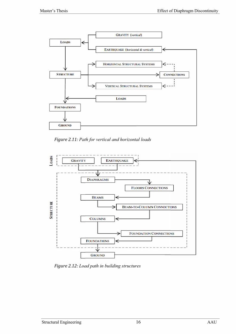
2.4.3.2. Vertical load path
Earthquake - resistant structures should be provided with lateral and vertical seismic force –
resisting systems capable of transmitting inertial forces from the location of masses
throughout the structure to the foundations. Structures designed for gravity loads have very
limited capacity to withstand horizontal loads. Inadequate lateral resisting systems and
connections interrupt the load path. Continuity and regular transitions are essential
requirements to achieve adequate load paths as shown in Figure 2.11.
In framed structures, gravity and inertial loads generated at each storey are transmitted first
to the beams by floor diaphragms (or slabs), then to columns and foundations as presented in
Figure 2.12.
Mechanical and geometrical properties of beam - to - column and column - to - base
connections may alter the load path. Continuity between structural components is vital for
the safe transfer of the seismic forces to the ground. Failure of buildings during earthquakes
is often due to the inability of their parts to work together in resisting lateral forces[1].
Master’s Thesis Effect of Diaphragm Discontinuity
Structural Engineering 15 AAU
Figure 2.10: Stress concentrations caused by small (left) and large (right) openings in horizontal
diaphragms
2.4.3.2. Vertical load path
Earthquake - resistant structures should be provided with lateral and vertical seismic force –
resisting systems capable of transmitting inertial forces from the location of masses
throughout the structure to the foundations. Structures designed for gravity loads have very
limited capacity to withstand horizontal loads. Inadequate lateral resisting systems and
connections interrupt the load path. Continuity and regular transitions are essential
requirements to achieve adequate load paths as shown in Figure 2.11.
In framed structures, gravity and inertial loads generated at each storey are transmitted first
to the beams by floor diaphragms (or slabs), then to columns and foundations as presented in
Figure 2.12.
Mechanical and geometrical properties of beam - to - column and column - to - base
connections may alter the load path. Continuity between structural components is vital for
the safe transfer of the seismic forces to the ground. Failure of buildings during earthquakes
is often due to the inability of their parts to work together in resisting lateral forces[1].
Master’s Thesis Effect of Diaphragm Discontinuity
Structural Engineering 16 AAU
Figure 2.11: Path for vertical and horizontal loads
Figure 2.12: Load path in building structures
Master’s Thesis Effect of Diaphragm Discontinuity
Structural Engineering 16 AAU
Figure 2.11: Path for vertical and horizontal loads
Figure 2.12: Load path in building structures
Master’s Thesis Effect of Diaphragm Discontinuity
Structural Engineering 16 AAU
Figure 2.11: Path for vertical and horizontal loads
Figure 2.12: Load path in building structures

Master’s Thesis Effect of Diaphragm Discontinuity
Structural Engineering 17 AAU
2.4.3.3. Story drift
Figure 2.13: Load path in
building structures
2.4.3.4. Diaphragm rigidity
In order to estimate the diaphragm rigidity, it is necessary to predict the deflection of the
diaphragm under the influence of lateral loads. The various floor and roof systems that have
evolved primarily for the purpose of supporting gravity loads do not lend themselves easily
to analytical calculation of lateral deflections. Different codes give different
recommendation on diaphragm rigidity of a floor diaphragm. EBCS 8 recommends the rigid
body condition may be considered valid if the in-plane deviations of all points of the
Drift is defined as the relative lateral
displacement between two adjacent floors, and
the term drift index, is defined as the drift
divided by the story height. The relative lateral
displacement of buildings is sometimes
measured by an overall drift ratio or index,
which is the ratio of maximum lateral
displacement to the height of the building. More
commonly, however, an inter-story drift ratio,
angle, or index is used, which is defined as the
ratio of the relative displacement of a particular
floor to the story height at that level see Figure
2.13.
The lateral displacement or drift of a structural
system under wind or earthquake forces, is
important in structural stability of a building.
Excessive and uncontrolled lateral displacements
can create severe structural problems. Empirical
observations and theoretical dynamic response
studies have indicated a strong correlation
between the magnitude of inter-story drift and
building damage potential[3].

Master’s Thesis Effect of Diaphragm Discontinuity
Structural Engineering 18 AAU
diaphragm from their rigid body position are less than 5% of their respective absolute
displacements under the seismic load combination. FEMA 273 classifies the rigidity of a
floor diaphragm according to its behaviour, which can be computed as shown in the Table
2.1 below. [4,16].
Table 2.1: FEMA 273 diaphragm classification
FMA 273 Diaphragm classificationRigid Diaph < 0.5StoryStiff 0.5Story Diaph 2Story
Flexible Diaph > 2Story
Diaph – maximum diaphragm deformation; Story – average inter-story
drift of story directly below the diaphragm
Figure 2.14: Maximum diaphragm deflection and average drift of vertical element
2.4.3.5. Lateral force distribution
Floor diaphragms in reinforced concrete (RC) buildings are typically modeled as rigid
during the design phase and so the effect of in-plane diaphragm flexibility on the structure is
often not considered. For the rigid diaphragm model, the diaphragm has equal in-plane
displacements along its entire length under lateral load such that horizontal forces are
transferred to the vertical LLRS proportional to the relative stiffness of each frame. A
flexible diaphragm, however, exhibits in-plane bending due to lateral load, resulting in
additional horizontal displacements along its length. This can lead to damage of the
diaphragm due to high flexural stresses along its boundaries. This flexibility also increases
the lateral load transfer to frames that were not designed to carry these additional lateral
loads based on a rigid diaphragm model. If this effect is sizeable, it can lead to overloading
of structural elements[6].

Master’s Thesis Effect of Diaphragm Discontinuity
Structural Engineering 19 AAU
2.4.3.6. Natural period of vibration
The ground shaking during an earthquake contains a mixture of many sinusoidal waves of
different frequencies, ranging from short to long periods. The time taken by the wave to
complete one cycle of motion is called period of the earthquake wave. In general, earthquake
shaking of the ground has waves whose periods vary in the range 0.03 - 33sec. Even within
this range, some earthquake waves are stronger than the others. Intensity of earthquake
waves at a particular building location depends on a number of factors, including the
magnitude of the earthquake, the epicentral distance, the type of ground that the earthquake
waves traveled through before reaching the location of interest and rigidity of the structure,
flexible building undergoes larger relative horizontal displacements than rigid building[10].
Fundamental natural period T is an inherent property of a building. Any alterations made to
the building will change its T. Value of T depends on the building flexibility and mass; more
the flexibility, the longer is the T, and more the mass, the longer is the T. In general, taller
buildings are more flexible and have larger mass, and therefore, have a longer T. On the
contrary, low- to medium-rise buildings generally have shorter T[10].
2.5. Lateral force and lateral force resisting system
2.5.1. Lateral force
Lateral forces are typically considered to be those which act parallel to the ground plane and
may occur at many angles other than perfectly horizontal. Generally lateral forces are
considered to act transversely to the primary structural system.
Seismic Loads and wind are the most fundamental lateral forces. May be so small as to be
unnoticed, or large enough to level cities. They occur simultaneously with gravity loads.
Wind is really a very complex phenomenon with a complex interaction on a building
structure. It is influenced greatly by local terrain. When contacting a building, it can produce
pressures and suction forces on any surface of a building, plus internal pressures that tend to
balloon the building outward. Seismic loads are forces generated by inertia of building mass
as ground moves below the structure. It generates forces in direct proportion to the building's

Master’s Thesis Effect of Diaphragm Discontinuity
Structural Engineering 20 AAU
mass and stiffness. A massless building would in fact have no seismic forces with at all. By
altering the building's stiffness, a substantial change to seismic force is possible[1].
2.5.2. Lateral force resisting system
2.5.2.1. Vertical system
Structural and non - structural damage under earthquakes is caused by inadequate stiffness
and/or strength of vertical components of lateral structural systems used for buildings,
bridges and other types of construction. Vertical components may also fail because of
insufficiency or absence of ductility. To achieve satisfactory seismic performance, vertical
components of lateral resisting systems should comply with the structural requirements.
Seismic behaviour depends on materials of construction, system configurations and failure
modes[1].
Earthquake resistance can be achieved through a wide range of vertical systems, which can
range from free - standing columns to complex three - dimensional framed tubes and/or
cores. Figure 2.15 shows basic structural systems, which have been ranked according to their
lateral stiffness[1].
Columns are the simplest structural elements with lateral stiffness and strength. The
relationship between applied actions and lateral deformations depends on their geometric
and mechanical properties. The deformed shape of columns is generally characterized by
double curvature, thus inelastic demand can be concentrated at both ends[1].
Frames show higher stiffness, strength and ductility than free – standing columns because of
their deflected shape. Frame behaviour significantly depends on the relative rigidity of
structural members (beams and columns) and connections (beam - to - columns and base
columns)[1].
Frames with diagonal braces exhibit higher lateral stiffness and strength than moment
frames; the ductility of braced systems is generally endangered by the occurrence of member
(diagonal) buckling. Moment frames can be stiffened by infill panels. Infilled frames exhibit
higher stiffness, strength and ductility than bare frames. Under lateral seismic loads, infills

Master’s Thesis Effect of Diaphragm Discontinuity
Structural Engineering 21 AAU
behave like one diagonal compression brace. Infill panels are often made of brittle materials,
such as masonry or concrete, which crack due to their low tensile strength. Lateral stiffness
of braced and infilled frames can be enhanced by employing structural walls. These
elements usually exhibit high in - plane stiffness and resistance; their ductility depends
primarily on the detailing of the foundation connection and their shape. Walls can be
arranged to form rigid core systems. The latter possess high resistance but, as for structural
walls, their inelastic behaviour can be impaired by seismic details with low ductility[1].
Figure 2.15: Basic vertical structural systems with increasing
lateral stiffness ( from top left to bottom right )
2.5.2.2. Typical lateral force resisting system
Typical lateral force - resisting systems include the following:
(i) Moment - Resisting Frames, (ii) Braced Frames, (iii) Structural Walls
(iv) Hybrid Systems and (v) Tube Systems

Master’s Thesis Effect of Diaphragm Discontinuity
Structural Engineering 22 AAU
(i) Moment - Resisting Frames
Moment - resisting frames (MRFs) are structural systems consisting of beams, columns and
joints. These systems are frequently used as structural skeletons in RC, steel and composite
buildings and bridges. Metal and composite MRFs can be classified according to the
stiffness and strength of the beam-to-column connections or the sensitivity to second - order
effects. Where stiffness is the response characteristic employed, frames can be ‘rigid’ or
‘semi - rigid’. Where, in turn, resistance is used, frames can be ‘full strength’ or ‘partial
strength’; the strength is quantified through the bending moment capacity. ‘Sway’ frames are
those with lateral stiffness inadequate to prevent secondary effects, e.g. P - Δ effects; in turn,
if these effects are negligible, the frames are described as ‘non - sway’[1].
(ii) Braced Frames
Braced frames (BFs) are lateral force - resisting systems, which consist of beams, columns,
diagonal braces and joints. Many brace configurations may be efficiently employed to
withstand earthquake loads. Braced frames are often grouped into two categories, i.e.
concentrically braced frames (CBFs) and eccentrically braced frames (EBFs), depending on
the layout of the diagonals employed[1].
(iii) Structural Walls
Structural walls (SWs) are vertical systems, which are frequently combined with RC, steel
and composite framed structures to control lateral deflections. These systems are often
classified according to their height - to - width (H/L) ratio (also known as vertical aspect
ratio) in ‘squat’ and ‘slender’ (or ‘cantilever’ ) walls. Squat walls have low slenderness: their
H/L ratios vary between 1 and 3. Slender or cantilever walls are those with H/L > 6. Under
horizontal loads, the ratio of bending - to - shear deflections of structural walls increases
with the system aspect ratio H/L[1].
(iv) Hybrid Frames
Rigid moment - resisting frames are ductile systems with high resistance, but their lateral
stiffness is often inadequate to prevent large drifts under earthquake forces. To reduce storey

Master’s Thesis Effect of Diaphragm Discontinuity
Structural Engineering 23 AAU
and roof drifts, MRFs are often connected to bracing systems or structural walls (also known
as ‘ hybrid frames or dual systems’). It is generally cost - effective for hybrid frames (HFs)
to employ frames that are designed for gravity loads only, while horizontal forces are
resisted by bracing systems, e.g. braced frames, or structural walls. Typical hybrid frame
system is shown below in Figure 2.16[1].
Figure 2.16: Typical hybrid frame, interaction between frame and structural wall
(v) Tube Systems
Tube systems (TSs) are structural systems in which lateral stiffness and strength are
provided by MRFs, BFs, SWs or hybrid systems that form either a single tube around the
perimeter of the structure, or nested tubes around the perimeter and core of the structure.
Tube systems are frequently used for high - rise structures[1].
2.6. Structural response characteristics
2.6.1. Stiffness
Stiffness defines the relationship between actions and deformations of a structure and its
components. Whereas member stiffness is a function of section properties, length and
boundary conditions, system stiffness is primarily a function of the lateral resisting
mechanisms utilized, e.g. moment – resisting frames, braced frames, walls or dual systems,
as illustrated in section 2.5[1].

Master’s Thesis Effect of Diaphragm Discontinuity
Structural Engineering 24 AAU
Several types of stiffness may be defined, depending on the nature of applied loads.
Structures designed for vertical (gravity) loads generally possess sufficient vertical stiffness.
Earthquakes generate inertial forces due to vibration of masses. Horizontal components of
these inertial forces are often dominant; hence lateral (or horizontal) stiffness is of primary
importance for structural earthquake engineers[1].
2.6.1.1. Factors influencing stiffness
i. Material Properties
Material properties that influence the structural stiffness are the elastic Young
’ s modulus E and the elastic shear modulus G.
ii. Section Properties
Section properties that affect the structural stiffness are the cross - sectional
area A , the flexural moment of inertia I and the torsional moment of inertia J.
iii. Member Properties
The lateral stiffness also depends on the type of structural members utilized to
withstand earthquake loads. Structural walls are much stiffer in their strong
axis than columns. Geometrical properties of structural components, such as
section dimensions, height and aspect ratio, influence significantly their
horizontal shear and flexural stiffness values.
iv. Connection Properties
Connection behaviour influences significantly the lateral deformation of
structural systems. For example, in multi - storey steel frames, 20 – 30% of
the relative horizontal displacement between adjacent floors is caused by the
deformability of the panel zone of beam - to - column connections.
v. System Properties
The lateral stiffness of a structure depends on the type of system utilized to
withstand horizontal earthquake loads, the distribution of the member
stiffness and the type of horizontal diaphragms connecting vertical members.
For example, moment - resisting frames (MRFs) are generally more flexible

Master’s Thesis Effect of Diaphragm Discontinuity
Structural Engineering 25 AAU
than braced frames. The latter class includes concentrically (CBFs) and
eccentrically (EBFs) braced frames. Structural walls are stiffer than all types
of frames. Frames with rigid connections exhibit higher stiffness than those
with semi - rigid connections. A vertical structural system for earthquake
resistance is provided in section 2.5. It suffices here to state that uniform
distribution of stiffness in plan and elevation is necessary to prevent
localization of high seismic demand.
Other theoretical backgrounds of structural response like diaphragm rigidity - in section
2.4.3.4, story drift in section - 2.4.3.3, lateral force distribution in section - 2.4.3.5 and
period in section - 2.4.3.6 are presented.
2.7. Method of analysis
The use of seismic analysis both in research and practice has increased substantially in
recent years due to the proliferation of verified and user - friendly software and the
availability of fast computers. The methods reviewed are grouped into static or dynamic
methods, which are applied in elastic and inelastic response analysis. Dynamic analysis is
the most natural approach towards the assessment of earthquake response, but is
significantly more demanding than static analysis in terms of computational effort and
interpretation of results[1].
Table 2.2: Comparisons of requirements for static and dynamic analyses

Master’s Thesis Effect of Diaphragm Discontinuity
Structural Engineering 26 AAU
Figure 2.17: Common methods of structural analysis used in earthquake engineering
Key : E = elastic analysis; I = inelastic analysis
2.7.1. Dynamic analysis
The equation of equilibrium for a multi - degree of freedom (MDOF) system subjected to
earthquake action is as follows[1]:
FI + FD + FR = FE ………………………………………………………….. 2.6.1
Where
FI - is the inertia force vector,
FD - the damping force vector,
FR - the vector of restoring forces and
FE - the vector of earthquake loads.
Equation 2.6.1 may be expressed as:

Master’s Thesis Effect of Diaphragm Discontinuity
Structural Engineering 27 AAU
+ + = − ………………………….…................................2.6.2
Where the inertia, damping and earthquake forces are expressed, respectively, as:
= ……….………………………………….…................................ 2.6.3
= …………………………………..……….…................................ 2.6.4
= − ……………………..……………….…................................ 2.6.5
In which M and C are the mass and damping matrices, xg the acceleration of the ground, x is
the vector of (absolute) accelerations of the masses and x is the vector of velocity relative to
the base of the structure, respectively. I is a vector of influence coefficients, i.e. the ith
component represents the acceleration at the ith degree of freedom due to a unit ground
acceleration at the base. For simple structural models with degrees of freedom corresponding
to the horizontal displacements at storey level, I is a unity vector. In this case, it represents
the rigid body acceleration of the structure due to a unit base acceleration. The use of MDOF
lumped systems for dynamic analyses results in a diagonal mass matrix M in which
translational and rotational masses are located along the main diagonal. The use of
consistent mass representations leads to a fully populated mass matrix. If the MDOF system
behaves linearly, the vector of the restoring forces in equation 2.6.1 can be expressed as
follows:
= ………………………………………….…................................ 2.6.6
In which k is the stiffness matrix and x the vector of displacements.
The matrix form of the dynamic equilibrium of motion given in equation 2.6.2 is identical to
the equation of motion for single - degree of freedom (SDOF) systems given by equation
2.6.7. However, mass, damping and restoring forces (or stiffness for linearly elastic
structures) for MDOF systems are expressed by matrices of coefficients representing the
additional degrees of freedom.
+ + = …….……………………………………….…....... 2.6.7

Master’s Thesis Effect of Diaphragm Discontinuity
Structural Engineering 28 AAU
Several methods of dynamic analysis of structures exist as shown in Figures 2.18. These
methods can be employed either in the time or the frequency domain. The most commonly
used methods for dynamic analysis of structures subjected to earthquake loads are modal,
spectral and response history. Among these methods modal and spectral analysis are
presented hereafter.
Figure 2.18: Common methods of structural analysis used in earthquake engineering
2.7.1.1. Modal and spectral analysis
The response of MDOF systems to a transient signal may be calculated by decomposing the
system into series of SDOF systems, calculating the response of each in the time domain and
then algebraically combining the response history to obtain the response of the MDOF
system.
If the analysis is only focused on the maximum response quantities, then the various modal
maxima are calculated under the effect of a response spectrum representing the transient

Master’s Thesis Effect of Diaphragm Discontinuity
Structural Engineering 29 AAU
signal, and the maxima are combined to give an upper bound of the maximum response of
the MDOF. This is modal spectral analysis, or spectral analysis for short.
Both the above methods are applicable only to linear elastic systems, since they employ
superposition. Modal analysis may be considered a time - domain solution, whereas it can be
argued that modal - spectral analysis is a frequency - domain solution.
Two concepts are needed for the development of modal analysis. These are the principle of
superposition and the convolution integral. Selection of earthquake spectra (input) and
adequate combinations of modes are essential to perform modal spectral analysis. For a
SDOF system, it can be shown that the displacement at time t is given by the solution of
equation 2.6.7. The coupled equation of motion for MDOF structures given in matrix form
in equation 2.6.2 can be rewritten for linearly elastic systems as follows[1]:
+ + = − ………..……………….…................................ 2.6.8
2.7.2. Static analysis
Static methods are generally used to assess the capacity or ‘ supply ’ of the structural system
in terms of actions and deformations at different limit states or performance objectives.
Static analysis may be viewed as a special case of dynamic analysis when damping and
inertia effects are zero or negligible. The equation of static equilibrium for a lumped MDOF
system can be derived from equation 2.6.1 by setting inertia FI and damping FD forces equal
to zero, leading to equation 2.6.9:
R = F(t) …………………………………………………………………………2.6.9
where
R - is the vector of restoring forces and
F (t) - the vector of the applied earthquake loads.

Master’s Thesis Effect of Diaphragm Discontinuity
Structural Engineering 30 AAU
The most commonly used static analysis method in earthquake engineering is outlined
below. Static methods can accommodate material inelasticity and geometric non - linearity.
They, however, provide reliable results only for regular structural systems[1].
2.7.2.1. Equivalent static analysis
Equivalent static analysis (also referred to as equivalent lateral force, ELF method) is the
simplest type of analysis that is used to assess the seismic response of structures. It is
assumed that the behavior is linear elastic (which corresponds to material linearity), while
geometrical non - linearity, i.e. second - order (P-Δ) effects, can be accounted for implicitly.
The horizontal loads considered equivalent to the earthquake forces are applied along the
height of the structure and are combined with vertical (gravity) loads. Methods of structural
analysis are used to solve the equilibrium equations for a MDOF system, e.g. equation 2.6.2
in which the vector of restoring forces can be assumed proportional to the vector of nodal
displacements of the structure.
The critical issue in equation 2.6.2 is often the load magnitude and distribution. With regard
to magnitude, the elastic forces are obtained from the mass of the structure and its
predominant period of vibration, and the earthquake spectrum is scaled by a response
modification factor. This factor is supposed to represent the ability of the structure to absorb
energy by inelastic deformation and damage. With regard to load distribution, the most
common is a code – type pattern corresponding to the predominant (usually fundamental)
mode of vibration. For buildings, inverted triangular or parabolic load patterns are often
used, depending on the period of the building. The magnitude of the force at each storey
level is also calculated from the predominant mode shape. A triangular distribution provides
a good approximation of horizontal forces for structures, which vibrate predominantly in the
first mode[1].
2.7.2.2. Second order P-delta effects
Typically, design codes require that second order P-Delta effects be considered when
designing concrete frames. These effects are the global lateral translation of the frame and
the local deformation of members within the frame.

Master’s Thesis Effect of Diaphragm Discontinuity
Structural Engineering 31 AAU
Consider the frame object shown in Figure 2.11, which is extracted from a story level of a
larger structure. The overall global translation of this frame object is indicated by . The
local deformation of the member is shown as . The total second order P-Delta effects on
this frame object are those caused by both and .
ETABS program has an option to consider P-Delta effects in the analysis. When P-Delta
effects are considered in the analysis, the program does a good job of capturing the effect
due to thedeformation shown in Figure 2.11, but it does not typically capture the effect of
thedeformation (unless, in the model, the frame object is broken into multiple elements
over its length)[13].
Figure 2.19: The total second order P-delta effects on a frame
element caused by both and
2.7.3. Elastic second-order analysis
The stiffnesses EI used in an analysis for strength design should represent the stiffnesses of
the members immediately prior to failure. This is particularly true for a second-order
analysis that should predict the lateral deflections at loads approaching ultimate. The EI
values should not be based totally on the moment-curvature relationship for the most highly

Master’s Thesis Effect of Diaphragm Discontinuity
Structural Engineering 32 AAU
loaded section along the length of each member. Instead, they should correspond to the
moment-end rotation relationship for a complete member.
Elastic second-order analysis consider section properties determined taking into account the
influence of axial loads, the presence of cracked regions along the length of the member, and
the effects of load duration[7].
ACI recommends the following properties for the members in the structure:
Table 2.3: ACI recommendation of stiffness modifiers for elastic second-order analysis
Compressionmembers
Columns 0.70Ig
Walls Uncracked 0.70IgCracked 0.35Ig
Flexural members Beams 0.35IgFlat plates and flat slabs 0.25Ig
Where
Ec - Modulus of elasticity concrete
Ig - Moment of inertia of gross concrete section
2.8. ETABS software
ETABS (Extended Three dimensional Analysis of Building System) is a sophisticated, yet
easy to use, special purpose analysis and design program developed specifically for building
systems. ETABS offers the widest assortment of analysis and design tools available for the
structural engineer working on building structures. The following list represents just a
portion of the types of systems and analyses that ETABS can handle easily:
Buildings with steel, concrete, composite or joist floor framing
Complex shear walls with arbitrary openings
Flat and waffle slab concrete buildings
Buildings subjected to any number of vertical and lateral load cases and
combinations, including automated wind and seismic loads
Floor modeling with rigid or semi-rigid diaphragms

Master’s Thesis Effect of Diaphragm Discontinuity
Structural Engineering 33 AAU
o Rigid and semi rigid options affect only the analysis of the model. If the rigid
option is selected, a fully rigid diaphragm is assumed, which causes all of its
constrained joints to move together as a planar diaphragm that is rigid against
membrane deformation. Effectively, all constrained joints are connected to
each other by links that are rigid in the plane but do not affect out-of-plane
(plate) deformation. If the semi rigid option is selected, the in-plane rigidity of
the diaphragm comes from the stiffness of the objects that are part of the
diaphragm. Semi rigid option gives the building the ability to behave as its
actual behaviour[13].
2.9. Finite element modeling
The finite element method was introduced in the early 1960s by scientists lik Argyris,
Clough and Zienkiewicz. Since then the method has been developed to be one of the most
powerful methods to solve engineering problems. Finite element method is based on matrix
algebra, and its efficiency depends directly on the performance of the computer. Nowadays,
when powerful computers are available, new methods of non-linear analysis are being
developed. The finite element method is today widely used especially in mechanical and
civil engineering.
Both analytical and finite element solutions are based on the governing differential
equations. The largest difficulty using analytical methods is to find a function that fulfils the
differential equation and the boundary condition over the entire body. Therefore, analytical
methods are limited to solving simple problems. Finite element method is an approximation
method that leads to division a structure into finite number of connected elements. The set of
elements is called finite element mesh and loads and boundary conditions are in the form of
concentrated forces in element nodes. The accuracy of finite element analysis depends on
size of elements and the order of so-called shape function. The latter is in most cases either
linear or quadratic[5].
The fundamental equation of equilibrium of the finite element method has the form of a
system of linear equations:
[K]{a} = {f}

Master’s Thesis Effect of Diaphragm Discontinuity
Structural Engineering 34 AAU
where
K - is global stiffness matrix
a - is nodal displacement vector
f - is force vector
2.10. Damage related to diaphragm
In a number of buildings, there has been evidence of roof diaphragms, which is caused by
tearing of the diaphragm. The following figure shows failure resulting from diaphragm
flexibility in Loma Prieta earthquake, 1989 (EERI, 1990), Figure 2.20[18].
Similarly, damage related to diaphragm response and behavior was observed in concrete
structures following the 1994 Northridge earthquake, primarily for precast construction. A
department store in the Northridge Fashion Center experienced damage to the roof
diaphragm (concrete fill over metal deck supported on steel beams) and to the floor
diaphragms (topping slab over precast elements) (Hamburger 1996)[6].
The Santa Monica College precast concrete parking structure experienced chord failure in
the diaphragm (Phillips 1996). Precast concrete parking structures at the Northridge Fashion
Center had diaphragm movement large enough to cause failure in some of the interior frame
columns designed for gravity loads and the Glendale Civic Center garage (cast-in place,
post-tensioned construction) had collector failures between the topping slab and a shear wall
(Corley et al. 1996) [6].

Master’s Thesis Effect of Diaphragm Discontinuity
Structural Engineering 35 AAU
Figure 2.20: (a) Diaphragm discontinuity; (b) Failure resulting from diaphragm flexibility
in Loma Prieta earthquake, 1989 (EERI, 1990)
Master’s Thesis Effect of Diaphragm Discontinuity
Structural Engineering 35 AAU
Figure 2.20: (a) Diaphragm discontinuity; (b) Failure resulting from diaphragm flexibility
in Loma Prieta earthquake, 1989 (EERI, 1990)
Master’s Thesis Effect of Diaphragm Discontinuity
Structural Engineering 35 AAU
Figure 2.20: (a) Diaphragm discontinuity; (b) Failure resulting from diaphragm flexibility
in Loma Prieta earthquake, 1989 (EERI, 1990)
Master’s Thesis Effect of Diaphragm Discontinuity
Structural Engineering 36 AAU
Chapter Three
3. Parametric Study
3.1. General
In this chapter, parametric studies of different cases are presented based on the theoretical
background acquired from previous chapters; to demonstrate the effect of diaphragm
discontinuity on the diaphragm rigidity and lateral load distribution to vertical element.
3.2. Description of the parametric study
Parametric studies are carried out for eight different cases, which are believed to verify
response of a structure with diaphragm discontinuity/opening. The parameters are story
height, shear wall width, number of stories, number of bays, shape of diaphragm opening,
size of diaphragm opening, span length and opening location in stories. In each parametric
study, four responses of structures; diaphragm rigidity, story drift, lateral force distribution
to vertical element and natural vibration period are evaluated. The response of story drift and
natural vibration period are not as such significant. Therefore, analysis results of diaphragm
rigidity and lateral force distribution to vertical element are presented and discussed.
The structures are analyzed for two key assumptions; actual diaphragm rigidity stiffness
(without diaphragm, WOD) and rigid diaphragm assumption (with diaphragm, WD). WOD
and WD terms are the method diaphragm analysis used to get actual diaphragm stiffness and
rigid diaphragm assumption using ETABS software according to section 2.8.
Analyses are carried out for 123 different model structures. Since the analyses are for two
major assumptions, a total of 246 structures are analyzed. From these structures
representative 35 /for two assumptions 70/ model structures are chosen and discussed in
detail.

Master’s Thesis Effect of Diaphragm Discontinuity
Structural Engineering 37 AAU
3.3. Modeling
3.3.1. Description of structures
A rectangular floor plan is selected for the parametric study. This floor plan shape was
chosen intentionally so that the selected case study structures can provide a critical structural
layout for evaluating diaphragm discontinuity/opening for actual diaphragm stiffness and
rigid diaphragm assumption.
Detailed descriptions of the structures are summarized in Table 3.1 below, which consists
structure codes, number of stories, number of bays, story height, opening size, shear wall
width and aspect ratio. From 123 model structures analyzed, 35 typical structures, which are
chosen for the discussion are tabulated below. The remaining structures are documented in
Appendix Table app1. Sample drawings of floor plan, section and 3D of three structures are
shown in Figure 3.1.
Table 3.1: Structures for parametric study
Structure type - code No ofstories
No ofbays
Storyheight,h (m)
Openingsize (%)
Shearwall
width,w (m)
Aspectratio
(LxW)
Remark
S1B2H25O50W2 1 2 2.5 50 2 2.66 Doublebay
S1B2H45O50W2 1 2 4.5 50 2 2.66 “S1B2H55O50W2 1 2 5.5 50 2 2.66 “S1B2H65O50W2 1 2 6.5 50 2 2.66 “S1B2H75O50W2 1 2 7.5 50 2 2.66 “S1B2H85O50W2 1 2 8.5 50 2 2.66 “S1B2H35O50 1 2 3.5 50 - 2.66 Without
shearwall
S1B2H35O50W1 1 2 3.5 50 1 2.66 Doublebay
S1B2H35O50W1.5 1 2 3.5 50 1.5 2.66 “S1B2H35O50W2 1 2 3.5 50 2 2.66 “S1B2H35O50W3 1 2 3.5 50 3 2.66 “S1B2H35O50W4 1 2 3.5 50 4 2.66 “S1B2H35O50W5 1 2 3.5 50 5 2.66 “S1B2H35O50W6 1 2 3.5 50 6 2.66 “S2B2H35O50W3 2 2 3.5 50 3 2.66 Same
heightS3B2H35O50W3 3 2 3.5 50 3 2.66 “

Master’s Thesis Effect of Diaphragm Discontinuity
Structural Engineering 38 AAU
Structure type - code No ofstories
No ofbays
Storyheight,h (m)
Openingsize (%)
Shearwall
width,w (m)
Aspectratio
(LxW)
Remark
S4B2H35O50W3 4 2 3.5 50 3 2.66 “S5B2H35O50W3 5 2 3.5 50 3 2.66 “S6B2H35O50W3 6 2 3.5 50 3 2.66 “S1B1H35O50W1.5 1 1 3.5 50 1.5 1.33 Single
bayS1B3H35O50W1.5 1 3 3.5 50 1.5 4.00 Three
baysS1B4H35O50W1.5 1 4 3.5 50 1.5 5.33 Four
baysS1B2H35O50W0.5R 1 2 3.5 50 0.5 2.66 Rectang
ularS1B2H35O50W0.5C 1 2 3.5 50 0.5 2.66 With
corridorat center
S1B2H35O50W0.5IR 1 2 3.5 50 0.5 2.66 Irregularopeningshape
S1B2H35O20W1.25 1 2 3.5 20 1.25 2.66 20%opening
S1B2H35O30W1.25 1 2 3.5 30 1.25 2.66 30%opening
S1B2H35O40W1.25 1 2 3.5 40 1.25 2.66 40%opening
S1B2H35O60W1.25 1 2 3.5 60 1.25 2.66 60%opening
S1B2H35O50W2-6x6 1 2 3.5 50 2 1.00 2@3mspan,
x-direc.S1B2H35O50W2-8x6 1 2 3.5 50 2 1.33 2@4m
span,x-direc.
S1B2H35O50W2-10x6 1 2 3.5 50 2 1.66 2@5mspan,
x-direc.S1B2H35O50W2-12x6 1 2 3.5 50 2 2.00 2@6m
span,x-direc.
S1B2H35O50W2-14x6 1 2 3.5 50 2 2.33 2@7mspan,
x-direc.S6B2H35O50-1FW3 6 2 3.5 50 3 2.66 Opening
at 1st
floorS6B2H35O50-3FW3 6 2 3.5 50 3 2.66 Opening
at 3rd
floorS6B2H35O50-6FW3 6 2 3.5 50 3 2.66 Opening
at 6th
floor

Master’s Thesis Effect of Diaphragm Discontinuity
Structural Engineering 39 AAU
(a)
(b)
(c)Figure 3.1: Sample drawings for
S1B2H35O50 (a), S1B2H35O50W3
(b) and S4B2H35O50W3 (c)
structures

Master’s Thesis Effect of Diaphragm Discontinuity
Structural Engineering 40 AAU
3.3.2. Material properties
Normal-weight concrete with a characteristic cube compressive strength of 25MPa and
characteristic yield strength of 400MPa for reinforcement is used for all members according
to EBCS-1[14].
A horizontal diaphragm of flat plate having a thickness of 250mm, which satisfy a
serviceability requirement according to EBCS-2[15] is modeled by finite-element method
using ETABS software.
3.3.3. Vertical element system
Main vertical element systems used for the parametric study are classified into two;
moment-resisting frame system, which consists only column as vertical element and hybrid
frame system (dual system), which consists of columns and shear walls as stated in section
2.5.2. The end shear wall is used to make the dual system, which is located in the center of
the shorter span of the rectangular floor plan. Based on the parametric study cases, one of
the above two vertical element systems is used at a time.
3.3.4. Loading
Loading on the structures consists of uniform live load of 5kN/m2 and imposed dead load of
3kN/m2. Permanent dead load of the structure is computed by the software using unit weight
of the concrete.
Lateral earthquake force for a bed rock acceleration ratio of 0.3g applied to the structure. It
is computed by equivalent static analysis method according to Ethiopian Building Code
Standard, EBCS-8[16].
A lateral load equal to the weight of the building is applied to the building in accordance
with the weight distribution, and the average inter-story drift, av, diaphragm deformation,
diaph, and shear force distribution to vertical element is computed.

Master’s Thesis Effect of Diaphragm Discontinuity
Structural Engineering 41 AAU
3.4. Analysis
Analyses are carried out using ETABS software, which is discussed in section 2.8. A total of
123 model structures are analyzed having various variables. Typical 35 structures are
selected and discussed below. Results for each case are presented below in tabular and
graphical format according to its category. The results of both diaphragm rigidity and lateral
load distribution to vertical element are recorded for the worst seismic force direction of the
floor plan. From section 2.4.3.4; EBCS 8 and FEMA 273 diaphragm rigidity classification,
FEMA 273 recommendation is selected due to its detail classification. In the analysis elastic
second-order effect is considered according to section 2.7.3.
3.5. Parametric studies of cases and discussions
Analysis result and discussion of typical 35 structures that are categorized into eight
parametric studies are presented hereafter. Table 3.2 shows lists of the parameters of each
case.
Table 3.2: Lists of parameters in eight cases
Cases Parametric studyCase – 1 Story height as a parameterCase – 2 Shear wall width as a parameterCase – 3 Number of stories as a parameterCase – 4 Number of bays as a parameterCase – 5 Shape of opening as a parameterCase – 6 Size of opening as a parameterCase – 7 Span length as a parameterCase – 8 Opening location in story as a parameter
3.5.1. Case – 1: Story height as a parameter
The first parametric study is carried out by considering the variation of story height as a
variable making the other constant. This is done by taking seven structures having different
story height. The structures are labeled by codes; S1B2H25O50W2, S1B2H35O50W2,
S1B2H45O50W2, S1B2H55O50W2, S1B2H65O50W2, S1B2H75O50W2 and S1B2H85O50W2 as
shown in Table 3.1. These structures have the same floor plan configuration with 50 percent
opening size. Vertical element systems are dual systems (hybrid/wall frame), which have

Master’s Thesis Effect of Diaphragm Discontinuity
Structural Engineering 42 AAU
300mmx500mm column size and 200mm thick and 2m wide shear wall. The only difference
is story height. The structures have 2.5m, 3.5m, 4.5m, 5.5m, 6.5m, 7.5m and 8.5m height
respectively. The analysis results for each response shown as below in a tabular and
graphical format and discussion follows.
i. Case – 1, Response – 1: Diaphragm rigidity
Table 3.3: Case – 1, Diaphragm rigidity summary for actual diaphragm stiffness
Structure type - Code Height(m)
diaph(mm)
av(mm)
FEMA 273classification
S1B2H25O50W2 2.5 1.635 0.210 7.79 FlexibleS1B2H35O50W2 3.5 2.379 0.599 3.97 FlexibleS1B2H45O50W2 4.5 2.798 1.319 2.12 FlexibleS1B2H55O50W2 5.5 3.042 2.464 1.23 StiffS1B2H65O50W2 6.5 3.202 4.139 0.77 StiffS1B2H75O50W2 7.5 3.320 6.454 0.51 StiffS1B2H85O50W2 8.5 3.416 9.529 0.36 Rigid
Figure 3.2: Case – 1, Story height versus diaphragm rigidity
7.79
3.97
2.12
1.23
0.77
0.51
0.36
0
1
2
3
4
5
6
7
8
9
0.0 1.0 2.0 3.0 4.0 5.0 6.0 7.0 8.0 9.0
Stor
y he
ight
, m
Diaphragm rigidity ratio (diaph/s)
Diaphragmrigidity
Story height vs diaphragm rigidity
Rigiddrr < 0.5
Stiff0.5 ≤ drr ≤ 2
Flexibledrr > 2
drr =diaphav

Master’s Thesis Effect of Diaphragm Discontinuity
Structural Engineering 43 AAU
ii. Case – 1, Response – 2: Lateral force distribution to vertical element
Table 3.4: Case – 1, Shear force distribution in column for WOD and WD assumption
Structure type -Code Height Column, C1 Column, C2
wod wd wod wd S1B2H25O50W2 2.5 3.23 4.51 -39.6 3.23 4.51 -39.6S1B2H35O50W2 3.5 3.70 4.42 -19.5 3.70 4.42 -19.5S1B2H45O50W2 4.5 4.15 4.57 -10.1 4.15 4.57 -10.1S1B2H55O50W2 5.5 4.54 4.80 -5.7 4.54 4.80 -5.7S1B2H65O50W2 6.5 4.89 5.07 -3.7 4.89 5.07 -3.7S1B2H75O50W2 7.5 5.23 5.35 -2.3 5.23 5.35 -2.3S1B2H85O50W2 8.5 5.55 5.64 -1.6 5.55 5.64 -1.6
Column, C3 Column, C4 Column, C5wod wd wod wd wod wd
24.41 4.03 83.5 24.41 4.03 83.5 3.23 4.51 -39.615.06 3.79 74.8 15.06 3.79 74.8 3.70 4.42 -19.510.21 3.77 63.1 10.21 3.77 63.1 4.15 4.57 -10.17.77 3.84 50.6 7.77 3.84 50.6 4.54 4.80 -5.76.50 3.94 39.4 6.50 3.94 39.4 4.89 5.07 -3.75.81 4.06 30.1 5.81 4.06 30.1 5.23 5.35 -2.35.42 4.17 23.1 5.42 4.17 23.1 5.55 5.64 -1.6
Column, C6wod wd 3.23 4.51 -39.63.70 4.42 -19.54.15 4.57 -10.14.54 4.80 -5.74.89 5.07 -3.75.23 5.35 -2.35.55 5.64 -1.6

Master’s Thesis Effect of Diaphragm Discontinuity
Structural Engineering 44 AAU
Figure 3.3: Case – 1, Story height versus shear force distribution for WOD and WD assumption
Discussion on case – 1 results /Story height as a parameter/
The discussion of the above two responses; diaphragm rigidity and lateral force distribution
to vertical element of the first parametric study are presented hereafter.
Analyses results shown in a tabular and graphical format above indicate diaphragm
discontinuity resulted in significant floor diaphragm rigidity difference between actual
diaphragm stiffness and rigid diaphragm assumption. As observed from the graph,
decreasing story height reduces the diaphragm rigidity. A 2.5m, 3.5m and a 4.5m height
floor has a flexible diaphragm; 5.5m, 6.5m and 7.5m height floor has a stiff diaphragm; and
8.5m height floor has a rigid floor. This is due to change in stiffness of a vertical element
system, which is resulted from the story height variation.
The relationship between vertical element height and stiffness is inverse; as the height
reduced the vertical element gets stiffer. Stiffness of a vertical element means resistance to
deformation. The larger the stiffness, the larger is the force required to deform it. For
24.41
15.06
10.21
7.77
6.5
5.81
5.42
4.03
3.79
3.77
3.84
3.94
4.06
4.17
0
1
2
3
4
5
6
7
8
9
0.0 5.0 10.0 15.0 20.0 25.0 30.0
Stor
y he
ight
, m
Shear force, kN
C3-WOD
C3-WD
Story height vs shear force

Master’s Thesis Effect of Diaphragm Discontinuity
Structural Engineering 45 AAU
example; a short column is stiffer as compared to a tall column, and it attracts larger
earthquake force. From this concept when the vertical element gets stiffer the diaphragm
tendency to attract force reduced, therefore, it easily deforms and gets flexible.
Lateral force distribution to vertical element is the second response of this parametric study.
The analysis result of actual and rigid diaphragm assumption shows a diaphragm
discontinuity result in substantial change between the two analyses, especially in the
intermediate column, since the floor diaphragm experiences larger in-plane diaphragm
deformation in the middle due to the diaphragm discontinuity. The change is more
significant when the height is reduced, which result flexible diaphragm according to
response one discussion. In shear force distribution to vertical element, a maximum of 83.5
percent difference is observed for a flexible 2.5m high floor; and a minimum of 23.1 percent
difference is observed for a rigid 8.5m high floor diaphragm in actual diaphragm stiffness
and rigid diaphragm assumption. As discussed above this is mainly because when height
reduced the vertical element gets stiffer; the larger the stiffness, the larger is the force
required to deform it; therefore, it attracts larger earthquake force. In addition, flexible
nature of the diaphragm that is resulted from the diaphragm discontinuity with height
reduction, gave tributary area force distribution that escalates the change in force distribution
between actual diaphragm stiffness and rigid diaphragm assumption.
3.5.2. Case – 2: Shear wall width as a parameter
The second parametric study is carried out by considering the variation of a vertical element
system as a parameter making the other constant. This is done by taking structures having
different shear wall width. The structures are labeled by codes; S1B2H35O50,
S1B2H35O50W1, S1B2H35O50W1.5, S1B2H35O50W2, S1B2H35O50W3 and S1B2H35O50W4,
as shown in Table 3.1. These structures have the same floor plan configuration with 50
percent diaphragm opening size and 300mmx500mm columns size. The difference between
the structures is shear wall width. They have a shear wall width of 0.0m (without shear
wall), 1.0m, 1.5m, 2.0m, 3.0m and 4.0m respectively. The transverse shear walls located in
the end frames provided a layout that maximizes the in-plane deformation of the diaphragms
because the interior frames are flexible relative to the stiffer end frames with shear walls.

Master’s Thesis Effect of Diaphragm Discontinuity
Structural Engineering 46 AAU
Analysis results are shown as below in a tabular and graphical format and discussion
follows.
i. Case – 2, Response – 1: Diaphragm rigidity
Table 3.5: Case – 2, Diaphragm rigidity summary for actual diaphragm stiffness
Structure type -Code
Shear wallwidth, (m)
diaph(mm)
av(mm)
FEMA 273classification
S1B2H35O50 0 0.683 8.151 0.08 RigidS1B2H35O50W1 1 1.902 2.600 0.73 StiffS1B2H35O50W1.5 1.5 2.243 1.176 1.91 StiffS1B2H35O50W2 2 2.379 0.599 3.97 FlexibleS1B2H35O50W3 3 2.463 0.218 11.29 FlexibleS1B2H35O50W4 4 2.464 0.114 21.54 Flexible
Figure 3.4: Case – 2, Shear wall width versus diaphragm rigidity
0.08
0.73
1.91
3.97
11.29
21.54
0
0.5
1
1.5
2
2.5
3
3.5
4
4.5
0 2 4 6 8 10 12 14 16 18 20 22 24
Shea
r wal
l wid
th, m
Diaphragm rigidity ratio (diaph/s)
Diaphragmrigidity
Shear wall width vs diaphragm rigidity
Rigiddrr < 0.5
Stiff0.5 ≤ drr ≤ 2
Flexibledrr > 2
drr =diaphav

Master’s Thesis Effect of Diaphragm Discontinuity
Structural Engineering 47 AAU
ii. Case – 2, Response – 2: Lateral force distribution to vertical element
Table 3.6: Case – 2, Shear force distribution in column for WOD and WD assumption
Structure type -Code
Shearwall
width
Column, C1 Column, C2
wod wd wod wd S1B2H35O50 0 41.63 42.79 -2.8 41.63 42.79 -2.8S1B2H35O50W1 1 14.92 16.47 -10.4 14.92 16.47 -10.4S1B2H35O50W1.5 1.5 7.00 8.02 -14.6 7.00 8.02 -14.6S1B2H35O50W2 2 3.70 4.42 -19.5 3.70 4.42 -19.5S1B2H35O50W3 3 1.49 1.94 -30.2 1.49 1.94 -30.2S1B2H35O50W4 4 0.90 1.22 -35.6 0.90 1.22 -35.6
Column, C3 Column, C4 Column, C5wod wd wod wd wod wd
43.38 41.06 5.3 43.38 41.06 5.3 41.63 42.79 -2.822.87 14.75 35.5 22.87 14.75 35.5 14.92 16.47 -10.417.34 7.05 59.3 17.34 7.05 59.3 7.00 8.02 -14.615.06 3.79 74.8 15.06 3.79 74.8 3.70 4.42 -19.513.50 1.55 88.5 13.50 1.55 88.5 1.49 1.94 -30.212.96 0.86 93.4 12.96 0.86 93.4 0.90 1.22 -35.6
Column, C6wod wd
41.63 42.79 -2.814.92 16.47 -10.47.00 8.02 -14.63.70 4.42 -19.51.49 1.94 -30.20.90 1.22 -35.6

Master’s Thesis Effect of Diaphragm Discontinuity
Structural Engineering 48 AAU
Figure 3.5: Case – 2, Shear wall width versus shear force distribution for WOD and WD
assumption
Discussion on case – 2 results /Shear wall width as a parameter/
In case – 2 parametric study, from the observation of the table and the graph, diaphragm
discontinuity became a serious concern; in diaphragm rigidity and lateral force distribution
to vertical element; in actual diaphragm stiffness and rigid diaphragm assumption as
discussed below.
The first discussion is on the diaphragm rigidity of the floor. Observation from the table and
the graph indicates that the change in dimension of the width of a shear wall plays a major
role on the relative rigidity of a diaphragm. 0, 1, 1.5, 2, 3 and 4 meter dimensions shear wall
width yields, rigid for 0 meter, stiff for 1 and 1.5 meter, flexible for 2, 3 and 4 meter
according to FEMA diaphragm classification. The major reason for this diaphragm rigidity
variation is, as the shear wall width dimension increases the vertical lateral load resisting
(VLLR) element (shear wall) gets stiffer. As discussed in case – 1 parametric study the
43.38
22.87
17.34
15.06
13.50
12.96
41.06
14.75
7.05
3.79
1.55
0.86
0
0.5
1
1.5
2
2.5
3
3.5
4
4.5
0.0 10.0 20.0 30.0 40.0 50.0
Shea
r wal
l wid
th, m
Shear force, kN
C3-WOD
C3-WD
Shear wall width vs shear force

Master’s Thesis Effect of Diaphragm Discontinuity
Structural Engineering 49 AAU
stiffer the VLLR element, the larger is the force required to deform it; therefore, it attracts
larger earthquake force. Therefore, when VLLR element attracts more forces, the diaphragm
tendency of force attraction reduced, which resulted changed in its rigidity behavior.
The second discussion of this parametric study is the distribution of shear force to vertical
element. Change in dimension of shear wall width seriously affects the distribution of the
lateral force. The table shows more than 50 percent difference is seen between actual
diaphragm stiffness and rigid diaphragm assumption for intermediate columns for a shear
wall width of 1.5m and above. The difference rises up to 93.4 percent for a shear wall width
of 4m. The basic reason for this variation is the change in rigidity of a floor diaphragm that
is influenced by diaphragm discontinuity.
The effects of diaphragm discontinuity influenced by stiffness of the vertical element that
can result relatively rigid, stiff or flexible diaphragm. In a condition where the diaphragm
rigidity is affected by flexibility, the variation in force distribution became large and
significant as shown in the table. As discussed in detail in case – 1 parametric study the
flexibility of the diaphragm resulted in tributary area load distribution in a floor. Therefore,
the effect of diaphragm discontinuity on lateral load distribution to vertical element when the
stiffness of the vertical elements varies, become a serious issue.

Master’s Thesis Effect of Diaphragm Discontinuity
Structural Engineering 50 AAU
3.5.3. Case – 3: Number of stories as a parameter
In case 3 number of variations of the stories are taken as a parameter. The structures have a
dual systems (hybrid/wall frame) vertical element, with column size 300mmx500mm and a
shear wall having 200mm thick and 3m width. The structures are labeled by codes;
S1B2H35O50W3, S2B2H35O50W3, S3B2H35O50W3, S4B2H35O50W3, S5B2H35O50W3 and
S6B2H35O50W3. All structures have the same floor plan and vertical element configuration
and 50 percent diaphragm opening size. The difference is number of stories. The structures
have 1-story, 2-story, 3-story, 4-story, 5-story and 6-story floors respectively. Results are
shown as below in a table and graphical format.
i. Case – 3, Response – 1: Diaphragm rigidity
Table 3.7: Case – 3, Diaphragm rigidity summary for actual diaphragm stiffness
Structure type -Code
Story diaph(mm)
av(mm)
FEMA 273classification
S1B2H35O50W3 1 2.463 0.218 11.29 Flexible
S2B2H35O50W3 2 4.448 1.586 2.80 Flexible1 1.800 0.957 1.88 Stiff
S3B2H35O50W33 5.064 3.809 1.33 Stiff2 3.495 3.406 1.03 Stiff1 1.402 1.685 0.83 Stiff
S4B2H35O50W3
4 5.320 8.474 0.63 Stiff3 4.334 8.416 0.52 Stiff2 2.865 6.835 0.42 Rigid1 1.053 3.175 0.33 Rigid
S5B2H35O50W3
5 5.446 12.386 0.44 Rigid4 4.834 12.666 0.38 Rigid3 3.718 11.680 0.32 Rigid2 2.351 8.984 0.26 Rigid1 0.829 3.957 0.21 Rigid
S6B2H35O50W3
6 5.512 18.141 0.30 Rigid5 5.201 18.852 0.28 Rigid4 4.268 18.451 0.23 Rigid3 3.150 16.496 0.19 Rigid2 1.970 12.290 0.16 Rigid1 0.640 5.263 0.12 Rigid
drr =diaphav

Master’s Thesis Effect of Diaphragm Discontinuity
Structural Engineering 51 AAU
Figure 3.6: Case – 3, Number of stories versus diaphragm rigidity
Note: - The graph is for roof floor rigidity only
ii. Case – 3, Response – 2: Lateral force distribution to vertical element
Table 3.8: Case – 3, Shear force distribution in column for WOD and WD assumption
Structure type -Code Story Column, C1 Column, C2
wod wd wod wd S1B2H35O50W3 1 1.49 1.94 -30.2 1.49 1.94 -30.2
S2B2H35O50W3 2 3.79 4.03 -6.3 3.79 4.03 -6.31 4.34 4.38 -0.9 4.34 4.38 -0.9
S3B2H35O50W33 8.12 8.36 -3.0 8.12 8.36 -3.02 5.59 5.48 2.0 5.59 5.48 2.01 6.40 6.51 -1.7 6.40 6.51 -1.7
S4B2H35O50W3
4 15.90 16.29 -2.5 15.90 16.29 -2.53 11.96 11.54 3.5 11.96 11.54 3.52 11.06 11.39 -3.0 11.06 11.39 -3.01 10.58 10.35 2.2 10.58 10.35 2.2
0.30
0.44
0.63
1.33
2.80
11.29
0
1
2
3
4
5
6
7
0 2 4 6 8 10 12
Num
ber o
f sto
ries
Diaphragm rigidity ratio (diaph/s)
Diaphragmrigidity
Number of stories vs diaphragm rigidity
Rigiddrr < 0.5
Stiff0.5 ≤ drr ≤ 2
Flexibledrr > 2

Master’s Thesis Effect of Diaphragm Discontinuity
Structural Engineering 52 AAU
Structure type -Code Story Column, C1 Column, C2
wod wd wod wd
S5B2H35O50W3
5 22.26 22.77 -2.3 22.26 22.77 -2.34 15.70 15.09 3.9 15.70 15.09 3.93 17.12 17.34 -1.3 17.12 17.34 -1.32 13.53 13.65 -0.9 13.53 13.65 -0.91 11.95 11.64 2.6 11.95 11.64 2.6
S6B2H35O50W3
6 30.59 31.26 -2.2 30.59 31.26 -2.25 21.30 20.49 3.8 21.30 20.49 3.84 23.99 24.26 -1.1 23.99 24.26 -1.13 22.65 22.52 0.6 22.65 22.52 0.62 17.53 17.82 -1.7 17.53 17.82 -1.71 14.81 14.27 3.6 14.81 14.27 3.6
Structure type -Code Story C3 C4
wod wd wod wd S1B2H35O50W3 1 13.50 1.55 88.5 13.50 1.55 88.5
S2B2H35O50W3 2 2.90 1.87 35.5 2.90 1.87 35.51 11.92 3.81 68.0 11.92 3.81 68.0
S3B2H35O50W33 2.81 3.53 -25.6 2.81 3.53 -25.62 4.95 2.83 42.8 4.95 2.83 42.81 10.61 4.93 53.5 10.61 4.93 53.5
S4B2H35O50W3
4 5.38 6.13 -13.9 5.38 6.13 -13.93 6.07 5.27 13.2 6.07 5.27 13.22 6.49 4.96 23.6 6.49 4.96 23.61 11.26 7.57 32.8 11.26 7.57 32.8
S5B2H35O50W3
5 7.28 8.50 -16.8 7.28 8.50 -16.84 7.57 5.91 21.9 7.57 5.91 21.93 6.53 6.87 -5.2 6.53 6.87 -5.22 6.67 5.30 20.5 6.67 5.30 20.51 10.59 7.93 25.1 10.59 7.93 25.1
S6B2H35O50W3
6 9.72 11.50 -18.3 9.72 11.50 -18.35 9.63 7.43 22.8 9.63 7.43 22.84 8.42 8.43 -0.1 8.42 8.43 -0.13 7.48 7.88 -5.3 7.48 7.88 -5.32 7.43 5.99 19.4 7.43 5.99 19.41 10.86 9.22 15.1 10.86 9.22 15.1

Master’s Thesis Effect of Diaphragm Discontinuity
Structural Engineering 53 AAU
Structure type -Code Story C5 C6
wod wd wod wd S1B2H35O50W3 1 1.49 1.94 -30.2 1.49 1.94 -30.2
S2B2H35O50W3 2 3.79 4.03 -6.3 3.79 4.03 -6.31 4.34 4.38 -0.9 4.34 4.38 -0.9
S3B2H35O50W33 8.12 8.36 -3.0 8.12 8.36 -3.02 5.59 5.48 2.0 5.59 5.48 2.01 6.40 6.51 -1.7 6.40 6.51 -1.7
S4B2H35O50W3
4 15.90 16.29 -2.5 15.90 16.29 -2.53 11.96 11.54 3.5 11.96 11.54 3.52 11.06 11.39 -3.0 11.06 11.39 -3.01 10.58 10.35 2.2 10.58 10.35 2.2
S5B2H35O50W3
5 22.26 22.77 -2.3 22.26 22.77 -2.34 15.70 15.09 3.9 15.70 15.09 3.93 17.12 17.34 -1.3 17.12 17.34 -1.32 13.53 13.65 -0.9 13.53 13.65 -0.91 11.95 11.64 2.6 11.95 11.64 2.6
S6B2H35O50W3
6 30.59 31.26 -2.2 30.59 31.26 -2.25 21.30 20.49 3.8 21.30 20.49 3.84 23.99 24.26 -1.1 23.99 24.26 -1.13 22.65 22.52 0.6 22.65 22.52 0.62 17.53 17.82 -1.7 17.53 17.82 -1.71 14.81 14.27 3.6 14.81 14.27 3.6
Figure 3.7:
Case – 3,
Number of
stories
versus
shear force
distribution
for WOD
and WD
assumption
2.81
4.95
10.61
3.53
2.83
4.93
0.0
0.5
1.0
1.5
2.0
2.5
3.0
3.5
0.0 2.0 4.0 6.0 8.0 10.0 12.0
Num
ber o
f sto
ries
Shear force, kN
C3-S3-WOD
C3-S3-WD
Number of stories vs shear force

Master’s Thesis Effect of Diaphragm Discontinuity
Structural Engineering 54 AAU
Discussion on case – 3 results /Number of stories as a parameter/
The result for diaphragm rigidity and lateral load distribution to vertical element shows how
the effects of diaphragm discontinuity vary when number of stories increases. The
discussion presented as follows.
The computation for diaphragm rigidity according to FEMA diaphragm classification
shows; increasing number of stories increases the floor diaphragm rigidity. This is because;
when number of stories increases the building get flexible[10]. The flexibility of a building is
due to its vertical element system. Flexible building undergoes large displacement because it
cannot resist large force. A large displacement results in a larger inter story drift. Large
inter-story drift increases the relative diaphragm rigidity computed. From the table, a single
and a two story floor has a diaphragm rigidity ratio of 11.29 and 2.8 respectively with a
flexible diaphragm classification. When the number of stories rises to three and four the
diaphragm gets stiffer. Further increasing the stories result in a rigid diaphragm. This
indicates that, buildings with a low number of stories are more susceptible for diaphragm
rigidity; mainly, because of increment of rigidity of the building.
The second response of a case – 3 parametric study is lateral force distribution to vertical
element. As observed from the graph, the variation of the distribution of lateral force to
vertical element between actual and rigid diaphragm assumption is decreasing while number
of stories increases. For the intermediate column, a single story floor has 88.5 percent
difference between the two assumptions. This difference falls to -18.3 percent for a six story
floor. This is mainly due to the increase in relative rigidity of the diaphragm which is
increased when number of stories increases. Even though the difference is decreasing, the
value of differences are not negligible; it is a value that can bring serious change in vertical
element strength. From this observation and discussion, the effect of diaphragm
discontinuity, in lateral force distribution to vertical element, will become serious in low rise
building; because the lower the building the higher the vertical lateral load resisting element
stiffness and the higher the attraction of more forces, which result in a flexible diaphragm.
As discussed in the previous parametric study, flexibility of the diaphragm yields tributary
area distribution of lateral force that brings significant change between actual diaphragm
stiffness and rigid diaphragm assumption.
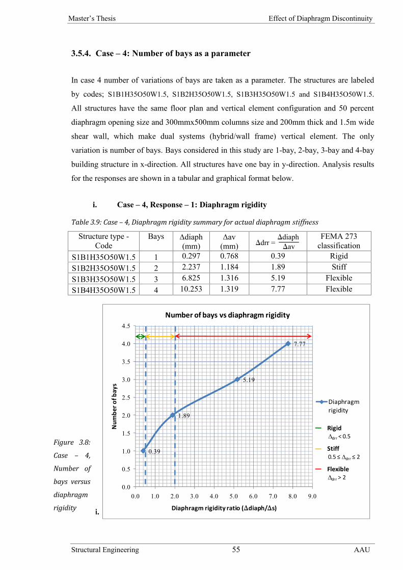
Master’s Thesis Effect of Diaphragm Discontinuity
Structural Engineering 55 AAU
3.5.4. Case – 4: Number of bays as a parameter
In case 4 number of variations of bays are taken as a parameter. The structures are labeled
by codes; S1B1H35O50W1.5, S1B2H35O50W1.5, S1B3H35O50W1.5 and S1B4H35O50W1.5.
All structures have the same floor plan and vertical element configuration and 50 percent
diaphragm opening size and 300mmx500mm columns size and 200mm thick and 1.5m wide
shear wall, which make dual systems (hybrid/wall frame) vertical element. The only
variation is number of bays. Bays considered in this study are 1-bay, 2-bay, 3-bay and 4-bay
building structure in x-direction. All structures have one bay in y-direction. Analysis results
for the responses are shown in a tabular and graphical format below.
i. Case – 4, Response – 1: Diaphragm rigidity
Table 3.9: Case – 4, Diaphragm rigidity summary for actual diaphragm stiffness
Structure type -Code
Bays diaph(mm)
av(mm)
FEMA 273classification
S1B1H35O50W1.5 1 0.297 0.768 0.39 RigidS1B2H35O50W1.5 2 2.237 1.184 1.89 StiffS1B3H35O50W1.5 3 6.825 1.316 5.19 FlexibleS1B4H35O50W1.5 4 10.253 1.319 7.77 Flexible
ii. C
Figure 3.8:
Case – 4,
Number of
bays versus
diaphragm
rigidity
0.39
1.89
5.19
7.77
0.0
0.5
1.0
1.5
2.0
2.5
3.0
3.5
4.0
4.5
0.0 1.0 2.0 3.0 4.0 5.0 6.0 7.0 8.0 9.0
Num
ber o
f bay
s
Diaphragm rigidity ratio (diaph/s)
Diaphragmrigidity
Number of bays vs diaphragm rigidity
Rigiddrr < 0.5
Stiff0.5 ≤ drr ≤ 2
Flexibledrr > 2
drr =diaphav

Master’s Thesis Effect of Diaphragm Discontinuity
Structural Engineering 56 AAU
ase – 4, Response – 2: Lateral force distribution to vertical element
Table 3.10: Case – 4, Shear force distribution in column for WOD and WD assumption
Structure type - Code Bays Column, C1 Column, C2wod wd wod Wd
S1B1H35O50W1.5 1 4.58 4.61 -0.7 4.58 4.61 -0.7S1B2H35O50W1.5 2 7.05 8.07 -14.5 7.05 8.07 -14.5S1B3H35O50W1.5 3 7.82 11.30 -44.5 7.82 11.30 -44.5S1B4H35O50W1.5 4 7.83 14.28 -82.4 7.83 14.28 -82.4
Column, C3 Column, C4 Column, C5wod wd wod wd wod wd 4.58 4.61 -0.7 4.58 4.61 -0.717.36 7.07 59.3 17.36 7.07 59.3 7.05 8.07 -14.531.31 9.25 70.5 31.31 9.25 70.5 31.31 9.25 70.535.08 11.58 67.0 35.08 11.58 67.0 53.18 10.74 79.8
Column, C6 Column, C7 Column, C8wod wd wod wd wod wd
7.05 8.07 -14.531.31 9.25 70.5 7.82 11.30 -44.5 7.82 11.30 -44.553.18 10.74 79.8 35.08 11.58 67.0 35.08 11.58 67.0
Column, C9 Column, C10wod wd wod wd
7.83 14.28 -82.4 7.83 14.28 -82.4

Master’s Thesis Effect of Diaphragm Discontinuity
Structural Engineering 57 AAU
Discussion on case – 4 results /Number of bays as a parameter/
The number of bays as a parameter is the fourth parametric study. From the analysis result,
here also, diaphragm discontinuity is the big deal. Both diaphragm rigidity and lateral load
distribution to vertical element are affected by floor opening.
From the analysis results shown in table and graph, increasing number of bays affect
seriously the rigidity of the diaphragm. It is obviously known that according to a rigid
diaphragm assumption, when lateral force is applied in the direction perpendicular to the
longer horizontal direction of the structure, change in horizontal displacement of parts of the
diaphragm is almost zero. Because the diaphragm is infinitely rigid. However, in actual
diaphragm stiffness analysis, a result of a floor diaphragm with diaphragm discontinuity
shows a change in horizontal displacement at the edge and center of the diaphragm.
Diaphragm deformation of (diaph) 0.2965, 2.2372, 6.8254 and 10.2525 for one, two, three
and four bays respectively observed. According to FEMA classification, these diaphragms
are rigid, stiff, flexible and flexible respectively.
Basically, when number of bays increases the diaphragm gets flexible. This is because
increasing number of bays in one direction make the building long and narrow. As stated in
section 2.3, a building having a long and narrow floor diaphragms act like flexible beam and
bending deflection of the diaphragm becomes significant. The long and narrow floor plan
with diaphragm discontinuity reduces in plane stiffness of the diaphragm. If the stiffness is
reduced it can easily deform and get flexible. Therefore, in this particular response of this
parametric study, diaphragm discontinuity is a significant factor which causes the bending or
bow action of the diaphragm that results in a flexible diaphragm.
Lateral force distribution to vertical element is the second response of this parametric study.
As clearly seen from the table the effect of diaphragm discontinuity on lateral force
distribution as number of bays increases is large and significant. 59.3 and 79.8 percent
lateral force distribution difference to vertical element between the two assumption for two
and four bays building structures are observed. This is mainly due to the flexible nature of
the diaphragm, which is resulted from increasing number of bays in one direction. The
flexibility of the diaphragm causes tributary area distribution of force in the floor; which

Master’s Thesis Effect of Diaphragm Discontinuity
Structural Engineering 58 AAU
cause the middle column to take large shear force that results in considerable differences
between actual diaphragm stiffness and rigid diaphragm assumption.
3.5.5. Case – 5: Shape of opening as a parameter
In case 5 variations of shape of openings are taken as a parameter. The structures are labeled
by codes; S1B2H35O50W0.5R, S1B2H35O50W0.5C and S1B2H35O50W0.5IR. All structures
have the same vertical element configuration and 50 percent diaphragm opening, and
300mmx500mm column size. The shear wall has 200mm thickness and 0.5m width. The
only variation is opening shape. Opening shapes taken in this study are; rectangular
(S1B2H35O50W0.5R), opening with corridor in the center (S1B2H35O50W0.5C) and irregular
shape opening (S1B2H35O50W0.5IR). The drawings are shown in Appendix B. Results for
each response shown as below in a tabular format.
i. Case – 5, Response – 1: Diaphragm rigidity
Table 3.11: Case – 5, Diaphragm rigidity summary for actual diaphragm stiffness
Structure type - Code Openingshape
diaph(mm)
av(mm)
FEMA 273classification
S1B2H35O50W0.5R Rectangular 1.2458 5.511 0.23 RigidS1B2H35O50W0.5C With corridor 1.6977 5.213 0.33 RigidS1B2H35O50W0.5IR Irregualr 2.7087 5.239 0.52 Stiff
ii. Case – 5, Response – 2: Lateral force distribution to vertical element
Table 3.12: Case – 5, Shear force distribution in column for WOD and WD assumption
Structure type - Code Openingshape
Column, C1 Column, C2wod wd wod wd
S1B2H35O50W0.5R Rectangular 30.08 31.84 -5.9 30.08 31.84 -5.9
S1B2H35O50W0.5CWith
corridor28.56 31.11 -8.9 28.56 31.11 -8.9
S1B2H35O50W0.5IR Irregualr 28.39 32.13 -13.2 28.39 32.13 -13.2
drr =diaphav

Master’s Thesis Effect of Diaphragm Discontinuity
Structural Engineering 59 AAU
Column, C3 Column, C4 Column, C5wod wd wod wd wod wd
33.96 29.36 13.5 33.96 29.36 13.5 30.08 31.84 -5.939.49 32.51 17.7 39.49 32.51 17.7 28.56 31.11 -8.938.92 28.98 25.5 38.92 28.98 25.5 28.39 32.13 -13.2
Column, C6wod wd
30.08 31.84 -5.928.56 31.11 -8.928.39 32.13 -13.2
Discussion on case – 5 results /Shape of opening as a parameter/
The fifth parametric study is a shape of opening. Various opening shape results in different
floor diaphragm rigidity behavior and lateral load distribution to vertical element due to the
presence of diaphragm discontinuity.
The first discussion is about diaphragm rigidity. The diaphragm rigidity computed for each
structure, according to FEMA classification, is shown in a table above. Observation from the
table shows different opening shape result in different diaphragm rigidity. A regular opening
shape with a rectangular shape results in a rigid diaphragm with diaphragm rigidity ratio
(diaph/av) equal to 0.23. But, an opening with irregular opening shape, with the same
size to rectangular opening shape, yields a stiff diaphragm, diaph/av is equal to 0.52. The
reason for the variation of diaphragm rigidity is the result of tributary area load distribution
to the intermediate section of the diaphragm that contributes to in-plane diaphragm
deformation. The larger the tributary area load distribution, the larger the in-plane
diaphragm deformation and the flexible the floor diaphragm. Therefore, if the shape of the
opening is more convenient for the tributary area load distribution, the diaphragm rigidity
behavior of the floor is easily affected.
The second response of this parametric study is the distribution of lateral force to vertical
element. According to the rigid diaphragm assumption, a diaphragm having 50 percent
diaphragm opening is rigid. From this statement, we expect the same result of lateral force
distribution to vertical element for actual diaphragm stiffness and rigid diaphragm

Master’s Thesis Effect of Diaphragm Discontinuity
Structural Engineering 60 AAU
assumption. However, the analysis result shows a large difference between the two analysis,
especially in cases where contribution of tributary area load distribution is large. The reason
is mainly because of flexible nature of the diaphragm that is resulted from the shape of the
opening as discussed above. S1B2H35O50W0.5IR structure has larger tributary area load
distribution than the other two structures, due to its shape. It has 25.5 percent variation in shear force
distribution to intermediate column between actual and rigid diaphragm assumption. This indicates
that, the shape of opening seriously affects effect of diaphragm discontinuity on distribution of lateral
load to the vertical element.
3.5.6. Case – 6: Size of opening as a parameter
In case 6 variations of size of openings are taken as a parameter. The structures are labeled
by codes; S1B2H35O20W1.25, S1B2H35O30W1.25, S1B2H35O40W1.25, S1B2H35O50W1.25
and S1B2H35O60W1.25. All structures have the same vertical element configuration. The
vertical element is a dual system (hybrid/wall frame). The column has 300mmx500mm
section size. The shear wall has 200mm thickness and 1.25m width. The variation between
the structures is opening size. Sizes of opening taken are; 20, 30, 40, 50 and 60 percent of
the total floor plan area. Analysis results are shown as below in a graphical and tabular
format.
i. Case – 6, Response – 1: Diaphragm rigidity
Table 3.13: Case – 6, Diaphragm rigidity summary for actual diaphragm stiffness
Structure type - Code Openingsize
diaph(mm)
av(mm)
FEMA 273classification
S1B2H35O20W1.25 20 0.9910 2.894 0.34 RigidS1B2H35O30W1.25 30 1.1932 2.523 0.47 RigidS1B2H35O40W1.25 40 1.5959 2.132 0.75 StiffS1B2H35O50W1.25 50 2.1061 1.737 1.21 StiffS1B2H35O60W1.25 60 2.9620 1.319 2.25 Flexible
drr =diaphav

Master’s Thesis Effect of Diaphragm Discontinuity
Structural Engineering 61 AAU
ii. Case – 6, Response – 2: Lateral force distribution to vertical element
Table 3.14: Case – 6, Shear force distribution in column for WOD and WD assumption
Structure type -Code
Openingsize
Column, C1 Column, C2Wod Wd wod wd
S1B2H35O20W1.25 20 16.89 17.34 -2.7 16.89 17.34 -2.7S1B2H35O30W1.25 30 14.74 15.36 -4.2 14.74 15.36 -4.2S1B2H35O40W1.25 40 12.47 13.40 -7.5 12.47 13.40 -7.5S1B2H35O50W1.25 50 10.16 11.42 -12.4 10.16 11.42 -12.4S1B2H35O60W1.25 60 7.69 9.50 -23.5 7.69 9.50 -23.5
Column, C3 Column, C4 Column, C5wod wd wod wd wod wd
20.75 15.90 23.4 20.75 15.90 23.4 16.89 17.34 -2.719.58 13.94 28.8 19.58 13.94 28.8 14.74 15.36 -4.219.33 12.04 37.7 19.33 12.04 37.7 12.47 13.40 -7.519.52 10.12 48.2 19.52 10.12 48.2 10.16 11.42 -12.421.18 8.23 61.1 21.18 8.23 61.1 7.69 9.50 -23.5
Figure 3.9: Case – 6, Size of opening versus diaphragm rigidity
0.34
0.47
0.75
1.21
2.25
0
10
20
30
40
50
60
70
0.0 0.5 1.0 1.5 2.0 2.5
Ope
ning
size
, %
Diaphragm rigidity ratio (diaph/s)
Diaphragmrigidity
Size of opening vs diaphragm rigidity
Rigiddrr < 0.5
Stiff0.5 ≤ drr ≤ 2
Flexibledrr > 2

Master’s Thesis Effect of Diaphragm Discontinuity
Structural Engineering 62 AAU
Column, C6wod wd
16.89 17.34 -2.714.74 15.36 -4.212.47 13.40 -7.510.16 11.42 -12.47.69 9.50 -23.5
Figure 3.10: Case – 6, Size of opening versus shear force distribution for WOD and WD assumption
Discussion on case – 6 results /Size of opening as a parameter/
In the study of the effect of diaphragm discontinuity, the size of the opening is a major factor
that affects diaphragm rigidity and lateral load distribution to vertical element. The
discussion is presented as follows.
The primary discussion is on how diaphragm discontinuity affects a rigidity of a diaphragm,
when different sizes of diaphragm openings are existed on a floor. Observation of results
20.75
19.58
19.33
19.52
21.18
15.90
13.94
12.04
10.12
8.23
0
10
20
30
40
50
60
70
0.00 5.00 10.00 15.00 20.00 25.00
Open
ing s
ize, %
Shear force, kN
C3-WOD
C3-WD
Size of opening vs shear force

Master’s Thesis Effect of Diaphragm Discontinuity
Structural Engineering 63 AAU
from the table and the graph shows increasing size of opening changes rigidity of the
diaphragm. For opening size 20, 30, 40, 50 and 60 diaphragm rigidity ratios are 0.34, 0.47,
0.75, 1.21 and 2.25 respectively. FEMA classification yields; rigid diaphragm for 20 and 30
percent opening size, stiff diaphragm for 40 and 50 percent opening size and rigid
diaphragm for 60 percent opening size.
The basic reason for diaphragm rigidity variation is increasing the opening size reduces parts
of the diaphragm that contribute to the rigidity of the diaphragm. When opening size get
larger, obviously in-plane membrane deformation of the diaphragm increases and the
diaphragm rigidity behaviour changes.
Lateral load distribution to vertical element is the second response of this parametric study.
As observed from the graph and the table when opening size increases, there is a significant
change between actual and rigid diaphragm assumptions on lateral load distribution.
Opening size 20, 30, 40, 50 and 60 have lateral load distribution difference; 23.4, 28.8, 37.7,
48.2 and 61.1 percent respectively, to the middle column between the two assumptions. The
basic reason for this variation is the change in the behavior of the diaphragm. As discussed
above when the opening size increases the diaphragm get stiff or flexible based on the size
of the opening. The flexibility of the diaphragm gives tributary area load distribution that
affects the middle column to take larger lateral forces unlike from the rigid diaphragm
assumption.
3.5.7. Case – 7: Span length as a parameter
The 7th case considers the variations of span length dimension as a parameter. The structures
are labeled by codes; S1B2H35O50W2-6x6, S1B2H35O50W2-8x6, S1B2H35O50W2-10x6,
S1B2H35O50W2-12x6, S1B2H35O50W2-14x6 and S1B2H35O50W2-16x6. All structures have
the same vertical element configuration. The shear wall has 200mm thickness and 2m width.
The variations between the structures are the dimension of the two span in x-direction.
Different span lengths that are taken in x-direction are; 2@3m, 2@4m, 2@5m, 2@6m,
2@7m and 2@8m. The y-direction span has a constant 6m length. Analysis results are
shown as below in a graphical and tabular format.

Master’s Thesis Effect of Diaphragm Discontinuity
Structural Engineering 64 AAU
i. Case – 7, Response – 1: Diaphragm rigidity
Table 3.15: Case – 7, Diaphragm rigidity summary for actual diaphragm stiffness
Structure type - CodeSpan(m)
diaph(mm)
av(mm)
FEMA 273classification
S1B2H35O50W2-6x6 6 0.1000 0.337 0.30 RigidS1B2H35O50W2-8x6 8 0.2775 0.398 0.70 StiffS1B2H35O50W2-10x6 10 0.5310 0.459 1.16 StiffS1B2H35O50W2-12x6 12 0.9470 0.513 1.85 StiffS1B2H35O50W2-14x6 14 1.5542 0.560 2.78 FlexibleS1B2H35O50W2-16x6 16 2.3792 0.599 3.97 Flexible
Figure 3.11: Case – 7, Span length versus diaphragm rigidity
0.30
0.70
1.16
1.85
2.78
3.97
0
2
4
6
8
10
12
14
16
18
0.0 1.0 2.0 3.0 4.0 5.0
Span
leng
th, m
Diaphragm rigidity ratio (diaph/s)
Diaphragmrigidity
Span length vs diaphragm rigidity
Rigiddrr < 0.5
Stiff0.5 ≤ drr ≤ 2
Flexibledrr > 2
drr =diaphav

Master’s Thesis Effect of Diaphragm Discontinuity
Structural Engineering 65 AAU
ii. Case – 7, Response – 2: Lateral force distribution to vertical element
Table 3.16: Case – 7, Shear force distribution in column for WOD and WD assumption
Structure type - Code Span Column, C1 Column, C2wod wd wod wd
S1B2H35O50W2-6x6 6 2.04 2.00 2.0 2.04 2.00 2.0S1B2H35O50W2-8x6 8 2.43 2.49 -2.5 2.43 2.49 -2.5S1B2H35O50W2-10x6 10 2.82 2.98 -5.7 2.82 2.98 -5.7S1B2H35O50W2-12x6 12 3.15 3.46 -9.8 3.15 3.46 -9.8S1B2H35O50W2-14x6 14 3.45 3.94 -14.2 3.45 3.94 -14.2S1B2H35O50W2-16x6 16 3.70 4.42 -19.5 3.70 4.42 -19.5
Column, C3 Column, C4 Column, C5wod wd wod wd wod wd 2.59 1.99 23.2 2.59 1.99 23.2 2.04 2.00 2.03.81 2.38 37.5 3.81 2.38 37.5 2.43 2.49 -2.55.39 2.74 49.2 5.39 2.74 49.2 2.82 2.98 -5.77.71 3.10 59.8 7.71 3.10 59.8 3.15 3.46 -9.810.90 3.45 68.3 10.90 3.45 68.3 3.45 3.94 -14.215.06 3.79 74.8 15.06 3.79 74.8 3.70 4.42 -19.5
Column, C6wod wd 2.04 2.00 2.02.43 2.49 -2.52.82 2.98 -5.73.15 3.46 -9.83.45 3.94 -14.23.70 4.42 -19.5

Master’s Thesis Effect of Diaphragm Discontinuity
Structural Engineering 66 AAU
Figure 3.12: Case – 7, Span length versus shear force distribution for WOD and WD assumption
Discussion on case – 7 results /Span length as a parameter/
The seventh parametric study is the span length as a parameter. Span length is one of the
factors that affect diaphragm discontinuity effect on diaphragm rigidity and lateral load
distribution to vertical element.
The first discussion is on the diaphragm rigidity of a floor. FEMA classification of the
diaphragm rigidity of the structures indicates; when the dimension of the span changes the
rigidity of the diaphragm also changes. In this parametric study, six structures with different
span lengths are analyzed and checked for diaphragm rigidity behavior. The result in the
table shows 2@3mx1@6m has a rigid diaphragm, 2@4mx1@6m, 2@5mx1@6m and
2@6mx1@6m has a stiff and 2@7mx1@6m and 2@8mx1@6m has a flexible diaphragm.
When the dimension of the span increases, the diaphragm rigidity is changed. Because,
increasing the span in one direction mean making the building structure narrow and long.
2.59
3.81
5.39
7.71
10.90
15.06
1.99
2.38
2.74
3.10
3.45
3.79
0
2
4
6
8
10
12
14
16
18
0.0 5.0 10.0 15.0 20.0
Span
leng
th, m
Shear force, kN
C3-WOD
C3-WD
Span length vs shear force

Master’s Thesis Effect of Diaphragm Discontinuity
Structural Engineering 67 AAU
Narrow and long building structure experiences stiff or flexible floor diaphragm based on
the dimension of the span as discussed in case – 4 parametric study. Therefore, from this
discussion, we can deduce that the span dimension is one of the factors that can change the
effects of diaphragm discontinuity on diaphragm rigidity.
Lateral load distribution to vertical element is the second discussion of this parametric study.
A dimension of span alters lateral load distribution to the vertical element comparing actual
and rigid diaphragm assumption. As discussed in detail in the above parametric study, the
difference is mainly due to the change in diaphragm rigidity of the floor that is resulted from
the change in span length. The larger the span length the flexible the diaphragm and the
higher the tributary area load distribution, which affects the intermediate column to take
large lateral forces.
3.5.8. Case – 8: Opening location in stories as a parameter
The 8th case considers the variations of location of opening in stories as a parameter, which
are labeled by S6B2H35O50-1FW3, S6B2H35O50-3FW3 and S6B2H35O50-6FW3. All
structures have the same vertical element configuration. The shear wall has 200mm
thickness and 3m width. The variations between the structures are the location of opening in
a six story building; the opening is located in 1st, 3rd and 6th floor. Analysis results are shown
as below in a graphical and tabular format.

Master’s Thesis Effect of Diaphragm Discontinuity
Structural Engineering 68 AAU
i. Case – 8, Response – 1: Diaphragm rigidity
Table 3.17: Case – 8, Diaphragm rigidity summary for actual diaphragm stiffness
Structure type - Code Storydiaph(mm)
av(mm)
FEMA 273classification
S6B2H35O50-1FW3
6 1.542 28.390 0.054 Rigid5 1.395 29.564 0.047 Rigid4 1.098 29.027 0.038 Rigid3 0.809 26.041 0.031 Rigid2 0.547 19.492 0.028 Rigid1 0.257 8.340 0.031 Rigid
S6B2H35O50-3FW3
6 1.609 29.067 0.055 Rigid5 1.420 30.247 0.047 Rigid4 1.265 29.693 0.043 Rigid3 1.910 26.248 0.073 Rigid2 0.584 19.531 0.030 Rigid1 0.164 8.336 0.020 Rigid
S6B2H35O50-6FW3
6 4.773 24.825 0.192 Rigid5 1.563 26.358 0.059 Rigid4 1.171 26.294 0.045 Rigid3 0.911 23.945 0.038 Rigid2 0.586 18.146 0.032 Rigid1 0.205 7.877 0.026 Rigid
Figure 3.13:
Case – 8,
Number of
stories versus
diaphragm
rigidity
Note: - The
graph is for
roof floor
rigidity only
0.059
0.045
0.038
0.032
0.026
0
1
2
3
4
5
6
7
0.00 0.02 0.04 0.06 0.08 0.10 0.12
Num
ber o
f sto
ries
Diaphragm rigidity ratio (diaph/s)
Diaphragmrigidity
Number of stories vs diaphragm rigidity
Rigiddrr < 0.5
Stiff0.5 ≤ drr ≤ 2
Flexibledrr > 2
drr =diaphav

Master’s Thesis Effect of Diaphragm Discontinuity
Structural Engineering 69 AAU
ii. Case – 8, Response – 2: Lateral force distribution to vertical element
Table 3.18: Case – 8, Shear force distribution in column for WOD and WD assumption
Structure type -Code
Story Column, C1 Column, C2wod wd wod wd
S6B2H35O50-1FW3
6 46.97 47.85 -1.9 46.97 47.85 -1.95 32.82 31.64 3.6 32.82 31.64 3.64 37.15 37.50 -0.9 37.15 37.50 -0.93 35.09 34.92 0.5 35.09 34.92 0.52 27.70 27.96 -0.9 27.70 27.96 -0.91 23.16 22.42 3.2 23.16 22.42 3.2
S6B2H35O50-3FW3
6 48.31 49.14 -1.7 48.31 49.14 -1.75 33.29 32.41 2.6 33.29 32.41 2.64 39.23 38.85 1.0 39.23 38.85 1.03 34.56 35.13 -1.6 34.56 35.13 -1.62 27.68 27.60 0.3 27.68 27.60 0.31 22.99 22.34 2.8 22.99 22.34 2.8
S6B2H35O50-6FW3
6 40.39 41.93 -3.8 40.39 41.93 -3.85 29.75 28.05 5.7 29.75 28.05 5.74 33.74 34.21 -1.4 33.74 34.21 -1.43 32.80 32.61 0.6 32.80 32.61 0.62 26.02 26.28 -1.0 26.02 26.28 -1.01 22.61 21.90 3.1 22.61 21.90 3.1
Structure type -Code
Story Column, C3 Column, C4wod wd wod wd
S6B2H35O50-1FW3
6 29.57 30.70 -3.8 29.57 30.70 -3.85 17.92 16.21 9.5 17.92 16.21 9.54 16.16 16.49 -2.0 16.16 16.49 -2.03 13.83 13.69 1.0 13.83 13.69 1.02 5.05 5.60 -10.9 5.05 5.60 -10.91 11.89 9.93 16.5 11.89 9.93 16.5
S6B2H35O50-3FW3
6 29.93 31.30 -4.6 29.93 31.30 -4.65 22.91 18.08 21.1 22.91 18.08 21.14 2.15 11.29 -425.1 2.15 11.29 -425.13 17.70 8.71 50.8 17.70 8.71 50.82 7.64 11.33 -48.3 7.64 11.33 -48.31 15.34 13.38 12.8 15.34 13.38 12.8

Master’s Thesis Effect of Diaphragm Discontinuity
Structural Engineering 70 AAU
Structure type -Code
Story Column, C3 Column, C4wod wd wod wd
S6B2H35O50-6FW3
6 25.76 18.58 27.9 25.76 18.58 27.95 13.00 18.82 -44.8 13.00 18.82 -44.84 17.84 16.80 5.8 17.84 16.80 5.83 14.19 14.36 -1.2 14.19 14.36 -1.22 9.88 9.59 2.9 9.88 9.59 2.91 15.05 13.86 7.9 15.05 13.86 7.9
Structure type -Code
Story Column, C5 Column, C6wod wd wod wd
S6B2H35O50-1FW3
6 46.97 47.85 -1.9 46.97 47.85 -1.95 32.82 31.64 3.6 32.82 31.64 3.64 37.15 37.50 -0.9 37.15 37.50 -0.93 35.09 34.92 0.5 35.09 34.92 0.52 27.70 27.96 -0.9 27.70 27.96 -0.91 23.16 22.42 3.2 23.16 22.42 3.2
S6B2H35O50-3FW3
6 48.31 49.14 -1.7 48.31 49.14 -1.75 33.29 32.41 2.6 33.29 32.41 2.64 39.23 38.85 1.0 39.23 38.85 1.03 34.56 35.13 -1.6 34.56 35.13 -1.62 27.68 27.60 0.3 27.68 27.60 0.31 22.99 22.34 2.8 22.99 22.34 2.8
S6B2H35O50-6FW3
6 40.39 41.93 -3.8 40.39 41.93 -3.85 29.75 28.05 5.7 29.75 28.05 5.74 33.74 34.21 -1.4 33.74 34.21 -1.43 32.80 32.61 0.6 32.80 32.61 0.62 26.02 26.28 -1.0 26.02 26.28 -1.01 22.61 21.90 3.1 22.61 21.90 3.1
Discussion on case – 8 results /Opening location in stories as aparameter/
The last parametric study is opening location in stories as a parameter. Similar to the above
discussion opening location in stories is one of the diaphragm discontinuity problems. The
diaphragm rigidity and lateral load distribution variation observed in the analysis is
discussed below.

Master’s Thesis Effect of Diaphragm Discontinuity
Structural Engineering 71 AAU
To evaluate the effect of opening location in different story levels, three building structures
having 50 percent opening in 1st, 3rd and 6th story levels are analyzed. According to FEMA
classification, the result in the table shows the three structures fall in rigid diaphragm
classification. This is mainly because the structures under study are a six story building,
which can be affected by building flexibility as discussed in detail in case – 3 parametric
study. High-rise building experiences relatively low vertical element stiffness, which
reduces its lateral load resisting capacity and resulting relatively a rigid floor diaphragm.
However, there is a slight variation of a diaphragm rigidity ratio between the three structures
where opening location varies, which mainly result change in lateral force distribution to
vertical element.
The second discussion is on results of lateral force distribution to vertical element. The result
in the table shows, there is a change in actual and rigid diaphragm assumption. An
intermediate column of a building structure with 2nd story-level opening has +50.8 percent
difference, between the two assumptions, which is the largest of the three structures. The
change in lateral force distribution is observed for a rigid diaphragm floor that is classified
as ‘rigid’ according to FEMA. First of all, the change is observed because, in rigid
diaphragm assumption, the diaphragm is infinitely rigid; but in FEMA rigidity classification,
the diaphragm will be classified as ‘rigid’ for a diaphragm rigidity ratio 0 to 0.5. Therefore,
we can expect variation in the lateral force distribution of the two assumptions for
diaphragm rigidity ratio greater than 0.00, because the diaphragm discontinuity affects in-
plane stiffness of the diaphragm. Whenever in-plane rigidity of the diaphragm is affected, it
results in a tributary area load distribution.
Master’s Thesis Effect of Diaphragm Discontinuity
Structural Engineering 72 AAU
3.6. Summary of discussion
A total of 123 reinforced concrete structures, 246 for two assumptions, were analyzed and a
typical 35, 70 for two assumptions, model structures were evaluated and discussed in detail
to assess the effect of size of diaphragm discontinuity on diaphragm rigidity and lateral load
distribution to vertical element. A basic structural layout of a building was selected to
maximize the in-plane deformation of the diaphragm to allow an evaluation of the potential
impact of diaphragm discontinuity on reinforced concrete structures. The analyses were
carried out for actual diaphragm stiffness and rigid diaphragm assumption in order to
investigate the effect of diaphragm discontinuity. For the analysis, ETABS 9.7 software is
used. The rigidity of the diaphragm is classified according to NEHRP guidelines (FEMA
273 diaphragm classification). Mainly, diaphragm discontinuity with 50 percent floor
diaphragm opening taken for the investigation as per the code provision, which is considered
as a rigid diaphragm.
In this chapter, eight parametric studies were carried out; story height, vertical element
system, number of stories, number of bays, shape of opening, size of opening, span length
and opening location in stories as a parameter. For each parametric study, four responses
were evaluated; diaphragm rigidity, story drift, lateral load distribution to vertical element
and natural vibration period. The responses of story drift and natural vibration period were
not as such significant. Therefore, analysis results of diaphragm rigidity and lateral force
distribution to vertical element were presented and discussed in detail. All the discussions
made are summarized as follows.
i. The stiffness of the vertical element system affect the effect of diaphragm
discontinuity on the responses of a structure based on case 1 and case 2 studies.
When a vertical element gets stiffer the relative in-plane stiffness of the
diaphragm reduced, which affects mainly diaphragm rigidity and lateral force
distribution to vertical element.
ii. Low-rise building structures are more susceptible to diaphragm discontinuity
than high-rise building, case 3 and 8 studies. Because the lower the building, the
rigid the building system and the stiffer the vertical element. When a vertical
element gets stiffer, the relative in-plane rigidity of the diaphragm affected,
which can change diaphragm behaviour and lateral force distribution.

Master’s Thesis Effect of Diaphragm Discontinuity
Structural Engineering 73 AAU
iii. The effect of diaphragm discontinuity in long and narrow building structure is
more serious than a building with short rectangular plan, case 4 and 7 studies.
Long and narrow building structure experiences flexible floor diaphragm, which
affect in-plane diaphragm stiffness. Change in in-plane diaphragm stiffness
affects diaphragm rigidity behavior and lateral load distribution.
iv. The shape of opening affects the effects of diaphragm discontinuity on
diaphragm rigidity and lateral load distribution to vertical element by varying
tributary area load distribution, case 5 study. When a shape contributing a larger
tributary area exists, the effect of diaphragm discontinuity on diaphragm rigidity
and lateral load distribution to vertical element get larger.
v. Opening size is one of the major factors that affects the effect of diaphragm
discontinuity on diaphragm rigidity and lateral load distribution to vertical
element, case 6 study. Increasing opening size reduces parts of the diaphragm
that contribute to the rigidity of the diaphragm. When opening size get larger,
obviously in-plane membrane deformation of the diaphragm increases and the
diaphragm rigidity behavior and lateral load distribution to vertical element
changes.
vi. For a building structure with moment-resisting frame, effects of diaphragm
discontinuity on diaphragm rigidity and lateral load distribution to vertical
element when actual diaphragm stiffness and rigid diaphragm assumption model
is used, the difference between the two assumptions is not appreciable. This is
due to the fact that the in-plane stiffness of the diaphragm is much larger than
the out-of-plane column stiffness.
vii. For a building structure with dual system, the effect of diaphragm discontinuity
between the two assumptions is large and significant. Because the dual system
consists a shear wall that gives large lateral stiffness to the vertical element,
which reduces the relative in-plane stiffness of the diaphragm.
viii. ASCE7 (2005) and Euro code 8 (2003) acknowledged that a diaphragm plan
aspect ratio greater than 3 and 4 respectively can result in considerable errors
when predicting the seismic response of building structures. However, it has
been observed that the aspect ratio of a diaphragm alone is not sufficient to
determine its rigidity. Mainly, the relative stiffness between the floor diaphragm
and the adjoining vertical lateral force resisting element systems should be
checked.

Master’s Thesis Effect of Diaphragm Discontinuity
Structural Engineering 74 AAU
Chapter Four
4. Conclusion and Recommendation
4.1. Conclusion
A total of 123 reinforced concrete structures were analyzed, and typical 35 model structures
were evaluated and discussed in detail to assess the effect of size of diaphragm discontinuity
on diaphragm rigidity and lateral load distribution to vertical element. In order to investigate
the effect, eight parametric studies were carried out; story height, vertical element system,
number of stories, number of bays, shape of opening, size of opening, span length and
opening location in stories as a parameter. For each parametric study, four responses were
evaluated; diaphragm rigidity, story drift, lateral load distribution to vertical element and
natural vibration period.
From the study, it is observed that effects diaphragm discontinuity on the response of a
structure cannot be overlooked. It results in changing the response of a structure
significantly differing from the same structure analyzed with rigid diaphragm assumption.
The difference in response mainly observed in diaphragm rigidity and lateral load
distribution to vertical element. The basic problem here is that the structure is subjected to
additional force and stress that are not considered in rigid diaphragm assumption.
Based on the analysis result, evaluation and discussion made in the previous chapter, the
following conclusions were made:
1. Effects of diaphragm discontinuity on diaphragm rigidity and lateral load
distribution to vertical element is mainly influenced by; vertical element stiffness,
number of stories, aspect ratio of the slab dimension, shape and size of the
diaphragm opening.
2. Stiffness of the vertical element is one of the most governing factors that
determine the effects of discontinuity on diaphragm rigidity and lateral load
distribution to vertical element. Because, the larger the stiffness, the larger is the
force required to deform it and the more the attraction of lateral force than the
floor diaphragm, which reduces the floor diaphragm lateral force resistance. This
results in the increase in the in-plane deformation of the diaphragm that changes

Master’s Thesis Effect of Diaphragm Discontinuity
Structural Engineering 75 AAU
diaphragm rigidity and lateral load deformation. Those results computed for
different parametric study; whether number of stories or bays, opening size or
shape mainly affected by the change in stiffness of the vertical element.
3. It has been observed that assessing the aspect ratio of a diaphragm alone is not
sufficient to determine its rigidity. Mainly, the relative stiffness between the floor
diaphragm and the adjoining vertical lateral force resisting element systems
should be checked.
4. For a building structure with dual system (hybrid/wall frame) vertical elements,
effects of discontinuity on diaphragm rigidity and lateral load distribution to
vertical element is larger and more significant than moment-resisting frame
system. This is mainly because the diaphragm attracts more lateral force for
moment-resisting frame than the stiffer dual systems.
5. Code provision of diaphragm discontinuity, which states that diaphragms having
cut out or open areas greater than 50 percent of the gross enclosed area of the
diaphragm, or changes in effective diaphragm stiffness of more than 50 percent
from one story to the next are affected by diaphragm discontinuity. However, it is
proved in this paper that, a diaphragm having not only 50 percent diaphragm
opening size but also a floor diaphragm with 30 and 40 percent opening size is
affected by diaphragm discontinuity. Therefore, the investigation has shown that
the code provision relating diaphragm rigidity to opening size is not always
satisfied.

Master’s Thesis Effect of Diaphragm Discontinuity
Structural Engineering 76 AAU
4.2. Recommendation
From all the above discussion and evaluation, it is concluded that diaphragm discontinuity is
a serious problem that can alter responses of a structure. The change in responses can affect
internal forces and stresses of a floor diaphragm as well as vertical element systems that
were not designed to carry those variations based on a rigid diaphragm assumption.
Therefore, the following recommendation is given regarding the size of opening of a floor
diaphragm to minimize the effect diaphragm discontinuity.
Code provision of 50 percent opening size, regarding its rigidity, is erratic, which is affected
by various factors discussed in chapter three. Therefore, generally, a small diaphragm
opening size is recommended in a floor diaphragm. Whenever opening size 30 percent and
above exists effects of diaphragm discontinuity on diaphragm rigidity and lateral load
distribution to vertical element should be checked, in structures, which have similar property
of parameters that are discussed in this paper.
4.3. Further research
This thesis focuses on certain parametric studies and responses of a structure to assess
effects of diaphragm discontinuity. However, further research can be made to investigate the
diaphragm discontinuity effect in varying horizontal and vertical plan configuration. This
can be done by taking number of parametric studies like different diaphragm opening
location, unsymmetrical opening shape, floor diaphragm shape with U, L and T. And
additional responses can also be checked like torsion and stress distribution in the diaphragm
for each parametric study.

Master’s Thesis Effect of Diaphragm Discontinuity
Structural Engineering 77 AAU
References:
1. Amr S. Elnashai, Luigi Di Sarno (2008), Fundamentals of Earthquake Engineering, John
Wiley & Sons, London, United Kingdom.
2. Ahmed Y. Elghazouli (2009), Seismic Design of Building to Eurocode 8, London ,United
Kingdom
3. Farzad Naeim, Ph.D., S.E.(2001), Seismic Design Handbook, Chapter 8- Seismic design
of floor diaphragm, Los Angeles, California..
4. Federal Emergency Management Agency (1997), NEHRP Guidelines for the Seismic
Rehabilitation of Buildings, FEMA-273, Washington, D.C.
5. O. C. Zienkiewicz, R. Tayler (2000), The Finite Element Method, 5th edition, Volume 1,
London, United Kingdom.
6. American Concrete Institute (2004), ACI Structural Journal, V. 101, No. 5, September-
October 2004, Farmington Hills, Michigan, USA.
7. American Concrete Institute (2002), “Building Code Requirements for Structural
Concrete (ACI 318-02) and Commentary (318R-02)”, Reported by ACI Committee 318,
Farmington Hills, Michigan, USA.
8. Portland Cement Association (2006), An Engineer’s Guide to Openings in Concrete Floor
Slabs, Washington, D.C.
9. Yousef Bozorgnia, Vitelmo V. Bertero (2006), Earthquake engineering from engineering
seismology to performance-based engineering, London ,United Kingdom.
10. C.V.R.Murty (2004), IITK-BMTPC Earthquake Tip 10, How Flexibility of Buildings
Affects Their Earthquake Response?, Kanpur, India.
11. Uniform Building Code (1997), International Conference of Building Officials, Structural
Engineering Provisions, Whittier, California.
12. Theodore C. Zsutty and Ronald P. Gallagher (1997), Seismic Design Manual, Volume I,

Master’s Thesis Effect of Diaphragm Discontinuity
Structural Engineering 78 AAU
Code Application Examples, California, USA.
13. Computers and Structures Inc. (2007), CSI analysis reference manual for SAP, ETABS
and SAFE, Berkeley California, USA.
14. Ethiopian Buildings Code Standard EBCS-1 (1995), “Basis of Design of Actions on
Structures”, Ministry of Urban and Works Development, Addis Ababa, Ethiopia.
15. Ethiopian Buildings Code Standard EBCS-2 (1995), “Structural Use of Concrete”,
Ministry of Urban and Works Development, Addis Ababa, Ethiopia.
16. Ethiopian Buildings Code Standard EBCS-8 (1995), “Design of Structures for Earthquake
Resistance”, Ministry of Urban and Works Development, Addis Ababa, Ethiopia.
17. Hasayoshi Nakashima, Ti Huang & Le-Wu Lu (1981), Effects of Diaphragm Flexibility
on Seismic Response of Building Structures, Washington, D.C.
18. Pankaj Agrawal, Manish Shrikhande (2006), Earthquake Resistant Design of Structures,
New Delhi, India.
19. American Society of Civil Engineers (2005), Minimum Design Loads for Building and
Other Structures (ASCE7-05), Structural Engineering Institute of the American Society of
Civil Engineers, Reston, Virginia.
20. Eurocode 8 (2003): Design of structures for earthquake resistance, Part 1: General rules,
seismic actions and rules for buildings, Brussels, Belgium.

Master’s Thesis Effect of Diaphragm Discontinuity
Structural Engineering 79 AAU
APPENDICES
Appendix A: All the Structures Analyzed for Parametric Study
Table app1: A total of 123-structures analyzed for parametric study
Structure type - code No ofstories
Noof
bays
Storyheight
(m)
Openingsize (%)
Shearwall
width(m)
Aspectratio
(LxW)
Columnsize(cm)
S1B2H25O50W2 C30X50 1 2 2.5 50 2 2.66 30x50S1B2H45O50W2 C30X50 1 2 4.5 50 2 2.66 30x50S1B2H55O50W2 C30X50 1 2 5.5 50 2 2.66 30x50S1B2H65O50W2 C30X50 1 2 6.5 50 2 2.66 30x50S1B2H75O50W2 C30X50 1 2 7.5 50 2 2.66 30x50S1B2H85O50W2 C30X50 1 2 8.5 50 2 2.66 30x50S1B2H35O50 C30X50 1 2 3.5 50 - 2.66 30x50S1B2H35O50W1 C30X50 1 2 3.5 50 1 2.66 30x50S1B2H35O50W2 C30X50 1 2 3.5 50 2 2.66 30x50S1B2H35O50W3 C30X50 1 2 3.5 50 3 2.66 30x50S1B2H35O50W4 C30X50 1 2 3.5 50 4 2.66 30x50S1B2H35O50W5 C30X50 1 2 3.5 50 5 2.66 30x50S1B2H35O50W6 C30X50 1 2 3.5 50 6 2.66 30x50S2B2H35O50W3 C30X50 2 2 3.5 50 3 2.66 30x50S3B2H35O50W3 C30X50 3 2 3.5 50 3 2.66 30x50S4B2H35O50W3 C30X50 4 2 3.5 50 3 2.66 30x50S5B2H35O50W3 C30X50 5 2 3.5 50 3 2.66 30x50S6B2H35O50W3 C30X50 6 2 3.5 50 3 2.66 30x50S1B1H35O50W2 C30X50 1 1 3.5 50 2 1.33 30x50S1B3H35O50W2 C30X50 1 3 3.5 50 2 4.00 30x50S1B4H35O50W2 C30X50 1 4 3.5 50 2 5.33 30x50S1B2H35O50W1C C30X50 1 2 3.5 50 1 2.66 30x50S1B2H35O50W1IR C30X50 1 2 3.5 50 1 2.66 30x50S1B2H35O20W2 C30X50 1 2 3.5 20 2 2.66 30x50S1B2H35O30W2 C30X50 1 2 3.5 30 2 2.66 30x50S1B2H35O40W2 C30X50 1 2 3.5 40 2 2.66 30x50S1B2H35O60W2 C30X50 1 2 3.5 60 2 2.66 30x50S1B2H35O50W3-6x6 C30X50 1 2 3.5 50 3 1.00 30x50S1B2H35O50W3-8x6 C30X50 1 2 3.5 50 3 1.33 30x50S1B2H35O50W3-10x6 C30X50 1 2 3.5 50 3 1.66 30x50S1B2H35O50W3-12x6 C30X50 1 2 3.5 50 3 2.00 30x50S1B2H35O50W3-14x6 C30X50 1 2 3.5 50 3 2.33 30x50

Master’s Thesis Effect of Diaphragm Discontinuity
Structural Engineering 80 AAU
Structure type - code No ofstories
Noof
bays
Storyheight
(m)
Openingsize (%)
Shearwall
width(m)
Aspectratio
(LxW)
Columnsize(cm)
S6B2H35O50-1FW3 C30X50 6 2 3.5 50 3 2.66 30x50S6B2H35O50-3FW3 C30X50 6 2 3.5 50 3 2.66 30x50S6B2H35O50-6FW3 C30X50 6 2 3.5 50 3 2.66 30x50S1B1H35O50C30X50 1 1 3.5 50 - 1.33 30x50S1B2H25O50C30X50 1 2 2.5 50 - 2.66 30x50S1B2H45O50C30X50 1 2 4.5 50 - 2.66 30x50S1B2H55O50C30X50 1 2 5.5 50 - 2.66 30x50S1B2H70O50C30X50 1 2 7.0 50 - 2.66 30x50S1B2H35O50C30X50 1 2 3.5 50 - 2.66 30x50S3B2H35O50C30X50 3 2 3.5 50 - 2.66 30x50S4B2H35O50C30X50 4 2 3.5 50 - 2.66 30x50S5B2H35O50C30X50 5 2 3.5 50 - 2.66 30x50S6B2H35O50C30X50 6 2 3.5 50 - 2.66 30x50S1B2H35O50CC30X50 1 2 3.5 50 - 2.66 30x50S1B2H35O50IRC30X50 1 2 3.5 50 - 2.66 30x50S1B2H35O20C30X50 1 2 3.5 20 - 2.66 30x50S1B2H35O30C30X50 1 2 3.5 30 - 2.66 30x50S1B2H35O40C30X50 1 2 3.5 40 - 2.66 30x50S1B2H35O60C30X50 1 2 3.5 60 - 2.66 30x50S1B2H70O50W1C30X50 1 2 7.0 50 1 2.66 30x50S1B2H70O50W2C30X50 1 2 7.0 50 2 2.66 30x50S1B2H70O50W3C30X50 1 2 7.0 50 3 2.66 30x50S1B2H35O30C40X60 1 2 3.5 30 - 2.66 30x50S1B2H35O40C40X60 1 2 3.5 40 - 2.66 40x60S1B2H35O50C40X60 1 2 3.5 50 - 2.66 40x60S2B2H25O50C30X50 2 2 2.5 50 - 2.66 30x50S2B2H25O50C40X60 2 2 2.5 50 - 2.66 40x60S2B2H25O50W1C40X60 2 2 2.5 50 1 2.66 40x60S2B2H25O50W3C40X60 2 2 2.5 50 3 2.66 40x60S2B2H30O50W1C40X60 2 2 3.0 50 1 2.66 40x60S2B2H30O50W3C40X60 2 2 3.0 50 3 2.66 40x60S4B2H30O50C30X50 4 2 3.0 50 - 2.66 30x50S4B2H30O50C40X60 4 2 3.0 50 - 2.66 40x60S4B2H30O50W1C40X60 4 2 3.0 50 1 2.66 40x60S4B2H30O50W3C40X60 4 2 3.0 50 3 2.66 40x60S6B2H25O50C30X50 6 2 2.5 50 - 2.66 30x50S6B2H35O30C30X50 6 2 3.5 30 - 2.66 30x50S6B2H35O30W1C30X50 6 2 3.5 30 1 2.66 30x50S6B2H35O30W3C30X50 6 2 3.5 30 3 2.66 30x50S6B2H35O30W6C30X50 6 2 3.5 30 6 2.66 30x50S6B2H35O40C30X50 6 2 3.5 40 - 2.66 30x50S6B2H35O40W1C30X50 6 2 3.5 40 1 2.66 30x50S6B2H35O40W3C30X50 6 2 3.5 40 3 2.66 30x50

Master’s Thesis Effect of Diaphragm Discontinuity
Structural Engineering 81 AAU
Structure type - code No ofstories
Noof
bays
Storyheight
(m)
Openingsize (%)
Shearwall
width(m)
Aspectratio
(LxW)
Columnsize(cm)
S6B2H35O40W6C30X50 6 2 3.5 40 6 2.66 30x50S1B3H35O30C30X50 1 3 3.5 30 - 4.00 30x50S1B3H35O40C30X50 1 3 3.5 40 - 4.00 30x50S1B3H35O50C30X50 1 3 3.5 50 - 4.00 30x50S1B3H35O30C40X60 1 3 3.5 30 - 4.00 40x60S1B3H35O40C40X60 1 3 3.5 40 - 4.00 40x60S1B3H35O50C40X60 1 3 3.5 50 - 4.00 40x60S2B3H25O50C30X50 2 3 2.5 50 - 4.00 30x50S2B3H25O50C40X60 2 3 2.5 50 - 4.00 40x60S2B3H30O50C40X60 2 3 3.0 50 - 4.00 40x60S2B3H30O50W1C40X60 2 3 3.0 50 1 4.00 40x60S4B3H30O50C30X50 4 3 3.0 50 - 4.00 30x50S4B3H30O50C40X60 4 3 3.0 50 - 4.00 40x60S4B3H30O50W1C40X60 4 3 3.0 50 1 4.00 40x60S6B3H35O30C30X50 6 3 3.5 30 - 4.00 30x50S6B3H35O40C30X50 6 3 3.5 40 - 4.00 30x50S6B3H35O50C30X50 6 3 3.5 50 - 4.00 30x50S6B3H35O30C40X60 6 3 3.5 30 - 4.00 40x60S6B3H35O40C40X60 6 3 3.5 40 - 4.00 40x60S6B3H35O50C40X60 6 3 3.5 50 - 4.00 40x60S1B4H35O30C30X50 1 4 3.5 30 - 5.33 30x50S1B4H35O50C30X50 1 4 3.5 50 - 5.33 30x50S1B4H35O40C30X50 1 4 3.5 40 - 5.33 30x50S2B4H25O50C30X50 2 4 2.5 50 - 5.33 30x50S2B4H30O50C30X50 2 4 3.0 50 - 5.33 30x50S4B4H30O50C30X50 4 4 3.0 50 - 5.33 30x50S6B4H35O30C30X50 6 4 3.0 30 - 5.33 30x50S6B4H35O40C30X50 6 4 3.5 40 - 5.33 30x50S6B4H35O50C30X50 6 4 3.5 50 - 5.33 30x50S6B4H35O30C40X60 6 4 3.5 30 - 5.33 40x60S6B4H35O40C40X60 6 4 3.5 40 - 5.33 40x60S6B4H35O50C40X60 6 4 3.5 50 - 5.33 40x60S1B2H25O50W3C30X50 1 2 2.5 50 3 2.66 30x50S1B2H45O50W3C30X50 1 2 4.5 50 3 2.66 30x50S1B2H55O50W3C30X50 1 2 5.5 50 3 2.66 30x50S1B2H65O50W3C30X50 1 2 6.5 50 3 2.66 30x50S1B2H75O50W3C30X50 1 2 7.5 50 3 2.66 30x50S1B2H85O50W3C30X50 1 2 8.5 50 3 2.66 30x50S1B1H35O50W3C30X50 1 1 3.5 50 3 1.33 30x50S1B3H35O50W3C30X50 1 3 3.5 50 3 4.00 30x50S1B4H35O50W3C30X50 1 4 3.5 50 3 5.33 30x50S1B2H35O50W3RC30X50 1 2 3.5 50 3 2.66 30x50S1B2H35O50W3CC30X50 1 2 3.5 50 3 2.66 30x50

Master’s Thesis Effect of Diaphragm Discontinuity
Structural Engineering 82 AAU
Structure type - Code No ofStories
Noof
bays
StoryHeight
(m)
Openingsize (%)
Shearwall
width(m)
Aspectratio
(LxW)
Columnsize(cm)
S1B2H35O50W3IRC30X50 1 2 3.5 50 3 2.66 30x50S1B2H35O20W3C30X50 1 2 3.5 20 3 2.66 30x50S1B2H35O30W3C30X50 1 2 3.5 30 3 2.66 30x50S1B2H35O40W3C30X50 1 2 3.5 40 3 2.66 30x50S1B2H35O60W3C30X50 1 2 3.5 60 3 2.66 30x50

Master’s Thesis Effect of Diaphragm Discontinuity
Structural Engineering 83 AAU
Appendix B: Sample and Representative Drawings
Figure B1: Drawings for S1B1H35O50W2
Figure B2: Drawings for S1B2H35O50W1R

Master’s Thesis Effect of Diaphragm Discontinuity
Structural Engineering 84 AAU
Figure B3: Drawings for S1B2H35O50W1C
Figure B4: Drawings for S1B2H35O50W1IR

Master’s Thesis Effect of Diaphragm Discontinuity
Structural Engineering 85 AAU
Figure B5: Drawings for S1B3H35O50W2

Master’s Thesis Effect of Diaphragm Discontinuity
Structural Engineering 86 AAU
DECLARATION
I, the undersigned, declare that this thesis is my work and all sources of materials used for
the thesis has been duly acknowledged.
Name Kassahun Memru
Signature ______________
Place Addis Ababa University
Institute of Technology
Date of submission July, 2013