Embed Size (px)
Citation preview
1 | P a g e
Faculty of Science and Technology
MASTER`S THESIS
Study program/specialization: Petroleum technology – Drilling
Spring semester, 2013
Open
Writer: Christian Steen
…………………………………………
(Writer`s signature)
Faculty supervisor: Kjell Kåre Fjelde External supervisor: Klaus Engelsgjerd Title of thesis: P&A operations today and improvement potential Credits:30 Key words: Regulations Challenges P&A tools Platform P&A Subsea P&A P&A program
Pages:103 + enclosures:12
Stavanger, 29/5 2013 dato/år

2 | P a g e
Acknowledgement
For the past 5 months I have been working continuously with this thesis and I’m proud of
presenting the result in the coming 100 pages. For their contributes to the thesis, I would like
to use this opportunity to share my gratitude toward several people
First of all I would like to thank the whole fishing department of Baker Hughes where I have
been sitting and working on my thesis. Thank you for your aid in providing information,
answering questions and creating a good social environment to work in. I hope we meet
again. Even though many people have been involved in the aiding process, I would like to pay
an extra gratitude towards some key persons in the working process.
I wish to express my gratitude toward Eivind Hagen at Baker Hughes for setting me up with
Baker Hughes for the thesis project. I probably would not have been writing here if it was not
for you. I will buy you a beer at a later occasion, mate.
I also want to send an extra thanks to my mentor at Baker Hughes, Klaus Engelsgjerd for
providing me with an office and for sharing your knowledge enthusiastically to raise my
understanding of the subject.
Extra gratitude also needs to be paid to Kjell Kåre Fjelde, my mentor at UiS, for your
continuous feedback and discussions around the thesis. Your contributions have helped to
form this thesis.
An extra thanks also to my family, friends and my girlfriend for continuously cheering me
forward. Your positive feedbacks have given a lot of motivation to keep working hard
throughout the entire process.

3 | P a g e
Abstract
Today rig/derrick and vessels is traditionally used to perform a P&A operation. With a rising
need for P&A operations combined with the wish of having a stable level of drilling
operations, a shortage of rigs will be a rising problem. Today’s operations are also time
consuming and costly for the operator, and fulfilling the regulations are often difficult.
Since plug and abandonment operations are a quite new operation faced on the NCS, the
development of tools/methods for this operation has been relative low. In order to handle
future challenges, new methods and tools needs to be developed. The operators have to take
the lead in this development, since the responsibilities of performing the operation lies with
them. The service companies needs to be encouraged to be innovative, and co operations
between companies will be needed. A higher focus on P&A should also be given at an earlier
stage, during the education of tomorrow’s personnel. New tools and methods can often be
hard to implement, since it usually means change in equipment and lack of experience with
the procedure. To be worth the risk, new tools should be developed in order to:
Save time
Save money
Provide better integrity
This thesis will present the tools and methods used today, and also try to take a closer look at
new techniques on the marked and on future developments. Challenges today will be
discussed and the thesis will also try to take a look into the crystal ball to see what the future
will bring.

4 | P a g e
Table of content Acknowledgement…………………………………………………………………………2
Abstract…………………………………………………………………………………….3
Table of content…………………………………………………………………………....4
List of figures………………………………………………………………………………7
List of abbreviations………………………………………………………………………..9
1. Introduction…………………………………………………………………………….11
2. Regulations……………………………………………………………………………..13
2.1...Norwegian regulations………………………………………………………………..13
2.2…The NORSOK D 010 regulations…………………………………………………....13
2.2.1..Definitions and number off barriers…………………………………………….....13
2.2.2..Well barrier criteria………………………………………………………………..16
2.2.3..Vertification requirements………………………………………………………...18
2.3...Comparing of NORSOK D 010 and UKOOA…………………………………….....19
2.4…How to set a barrier, summary……………………………………………………….21
3. Status on performance and outline of P&A operations……………………………..22
3.1.1..Operational overview……………………………………………………………….22
3.1.2..Abandonment program……………………………………………………………23
3.2…Operational processes, a closer look…………………………………………………26
3.2.1..Well diagnostic……………………………………………………………………26
3.2.2..Logging…………………………………………………………………………...26
3.2.2.1..Casing collar log………………………………………………………………27
3.2.2.2..Gamma log…………………………………………………………………….27
3.2.2.3..Cement bonding log…………………………………………………………...27
3.2.2.4..Cement mapping log…………………………………………………………..30
3.2.2.5..Ultrasonic cement mapping tool………………………………………………31
3.2.2.6..Ultrasonic imaging log………………………………………………………...32
3.2.3..Kill well……………………………………………………………………………33
3.2.4.. Perform clean out run, set cement plug and displacement of well………………..34
3.2.4.1..The bullhead cement method………………………………………………….34
3.2.4.2..The balanced plug method…………………………………………………….36

5 | P a g e
3.2.5..Pull tubing…………………………………………………………………………38
3.2.6..Cut and pull intermediate casings………………………………………………….38
3.2.6.1..Cutting tool…………………………………………………………………….39
3.2.6.2..Pulling tool……………………………………………………………………..40
3.2.7..Remove wellhead and conductor…………………………………………………..43
3.2.8..Remove platform/decommission…………………………………………………...44
3.3…Milling………………………………………………………………………………...45
3.4...Performing a P&A operation, summary……………………………………………….47
4. Field case, P&A of TOGI………………………………………………………………48
4.1…Introduction…………………………………………………………………………..48
4.1.2…Entering a subsea well……………………………………………………………48
4.2…The TOGI project, introduction……………………………………………………...49
4.2.2…The Oseberg field………………………………………………………………...49
4.2.3…The Oseberg field overview……………………………………………………...50
4.3…TOGI casing completion program and status when starting P&A operation……..…52
4.4…The P&A operation sequences ………………………………………………………53
4.5…TOGI P&A discussion……………………………………………………………….60
4.6…Summary of TOGI P&A……………………………………………………………..61
5. Existing technology and outline of new and improved methods…………………....62
5.1…Introduction………………………………………………………………………….62
5.2…Well barrier element materials………………………………………………………..62
5.3…Traditional plugging material………………………………………………………...63
5.3.1…Cement …………………………………………………………………………..63
5.3.2..Improvement potential ………………………………………………………..…..65
5.4…Alternative plugging materials…………………………………………………….…67
5.4.1…Sand slurry, Sandaband……………………………………………………….…67
5.4.2..Thermaset…………………………………………………………………….……69
5.4.3..Shale formation……………………………………………………………….…...70
5.5… A short overview of new plugging technology ……………………………….….....72
5.5.1..Cannseal…………………………………………………………………….….….72
5.5.2..Setled barite…………………………………………………………………..……72
5.5.3..BISN plug…………………………………………………………………….……72
5.6…Milling…………………………………………………………………………….…..73
5.6.1…Milling challenges…………………………………………………………….…..73

6 | P a g e
5.6.2…Improved milling technology………………………………………...………….75
5.6.2.1…P cutter……………………………………………………………………….75
5.6.2.2…G cutter………………………………………………………………….…...76
5.6.2.3…Glyphaloy cutter………………………………………………………….….76
5.6.2.4..Downhole optimization sub……………………………………………….…..77
5.6.2.5..SwarfPak…………………………………………………………………...….77
5.7. Alternative to section milling, Hydrawash system……………………………………78
5.8…Improved cut and pull...........................................................................................…...80
5.8.1…Harpoon cut and pull spear…………………………………………………...….80
5.8.2…Hydraulic casing spear…………………………………………………………...80
5.8.3…SERVCO……………………………………………………………………..….80
5.8.4…SERVCO 2M………………………………………………………………….…81
5.8.5…Multi cycle pipe cutter ……………………………………………………….….81
5.9…Challenges to be taken into consideration………………………………………..….81
5.9.1…Fulfilling the regulations………………………………………………………....81
5.9.2…Logging through several casings………………………………………...…….…83
5.9.3…Control cables………………………………………………………………….…83
6. The way further...............................................................................................................84
6.1…Introduction……………………………………………………………………..……84
6.2…Traditional choices entering a well for P&A……………………..…………….……85
6.2.1…Category A vessels, RLWI………………………………………………….…...86
6.2.2…Extended category A vessels……………………………………………….….…89
6.2.3…Category B…………………………………………………………………….…89
6.2.4…Rig/derrick…………………………………………………………………….…89
6.3…New: Pulling and jacking unit………………………………………………….…....92
6.4…My reflections………………………………………………….………………….…93
7. Conclusion and recommendations…………………………………………………….96
8. Reference……………………………………………………………………………….98
Appendices………………………………………………………………………………..104

7 | P a g e
List of figures
Figure 1: Statoil’s estimation of the future development for PP&A
Figure 2: Well barrier schematic
Figure 3: Acceptable well barrier
Figure 4: 2 separate barriers versus 1 combined barrier
Figure 5: Well cs-11 before abandonment
Figure 6: Well cs-11 after P&A operation
Figure 7: Wave amplitude transformed to VDL
Figure 8: A typical CBL display
Figure 9: CBL display also featuring cement mapping tool
Figure 10: Reflection waveforms and measurement aids
Figure 11: A cement log display indicating a partial cement job
Figure 12: Bull heading cement
Figure 13: Hydrostatic principle of the balancedplug method
Figure 14: Bowen itco spear
Figure 15: Abrasive water jet cutting through steel
Figure 16: Underreaming
Figure 17: The Oseberg field production profile
Figure 18: Oseberg field overview
Figure 19: TOGI casing completion program
Figure 20: TOGI well before P&A
Figure 21: Section milling BHA
Figure 22: Cutting BHA
Figure 23: Pulling BHA
Figure 24: TOGI well after P&A
Figure 25: Estimated rig days for the P&A operation
Figure 26: API cement classification
Figure 27: Potential leak paths in the cement
Figure 28: Stress-strain curve for a ductile material
Figure 29: Stress strain curve for a brittle material
Figure 30: Sandaband

8 | P a g e
Figure 31: Physical behavior of Sandaband
Figure 32: Mechanical properties of Thermaset
Figure 33: Swarf handling
Figure 34: Evolvement in cutting inserts
Figure 35: G cutter
Figure 36: Weardown of cutter with glyphaloy inserts
Figure 37: SwarfPak
Figure 38: HydraWash
Figure 39: Time spent on providing annulus barrier
Figure 40: Intervention alternatives
Figure 41: Vessels
Figure 42: Coiled tubing set up
Figure 43: Monohull vessel
Figure 44: Different selections of rig
Figure 45: Jack up rig
Figure 46: Pulling and jacking unit
Figure 47: Intervention cost

9 | P a g e
List of abbreviation
API – American Petroleum Institute
BHA – Bottom hole assembly
BOP – Blow out preventer
CBL – Cement bond log
CCL – Casing collar log
CET – Cement evaluation tool
CT – Coiled tubing
DHSV – Down hole safety valve
ECD – Equivalent circulation density
EZSV – Easy drill subsurface valve
FIT – Formation integrity test
HSE – Health, safety and environment
HPHT – High pressure and high temperature
ID – Inner diameter
IMR – Inspection, maintenance and repair
LCM – Lost circulation material
LMRP – Lower marine riser package
LWI – Light well intervention
MCPC - Multi cycle pipe cutter
MD – Measured depth
MPa – Mega Pascal
MSL – Main sea level
MS cutter – Multi-string cutter
NCS – Norwegian continental shelf
N/D – Nip down
N/U – Nip up
OD – Outer diameter
P&A – Plug and abandonment
PBR – Polished bore receptacle

10 | P a g e
PJU – Pull & jacking unit
POOH – Pull out of hole
PP&A – Permanent plug and abandonment
PSA – Petroleum Safety Authority
PSD – Particle size distribution
PWC – Perforate, wash and cement
RIH – Run in hole
RLWI – Riser less well intervention
TCT – True crystallization temperature
TH – Tubing hanger
THRT – Tubing hanger running tool
TOC – Top of cement
TOGI – Troll Oseberg gas injection
UKOOA – United kingdom offshore Operators association
USIT/CBL – Ultra sonic imaging tool/Cement bond log
VDL – Variable density log
WBE – Well barrier element
WBM – Water based mud
WH – Well head
WL – Wireline
WOC – Wait on cement
WOW – Wait on weather
XLOT – External leak off test
XMT – Xmas tree

11 | P a g e
1. INTRODUCTION
When a well is no longer profitable to produce, one can choose to plug the mother bore and
drill a sidetrack to perform a slot recovery or just plug the well. If the intention is to reenter
the well at a later time, you could perform a temporary abandonment. But if there are no
intention of ever reentering the well, one need to perform a permanent plug and abandonment
operation (I will refer to it just as just P&A in this thesis) to seal the well for eternity to ensure
no leak to the surface. A P&A operation is basically an operation where you remove the
necessary completion equipment and set a series of plugs. The goal of the operation is to close
the well down for eternity.
The production on the NCS is quite new. It started in 1969 with the discovery of our first field
Ekofisk. Many of our still producing fields were developed in the 70s and 80s. With
production over the top, many of them are closing in on the last stage in a wells life:
abandonment. Starting In the coming years and up to 2040, approximately 2000 wells need to
be abandoned. Around 200 of the wells are temporary abandoned and will, if new regulations
are approved, needed to be P&A within a timeframe of 3 years. New wells are also being
drilled as we speak, increasing the number of wells to be abandoned [11]. Figure 1 illustrates
this upcoming abandonment wave for Statoil. Since Statoil is the dominant operator on NCS
its natural to assume that it is representative for the entire NCS.
A typical P&A operation will take about 45 days to perform. This will of course vary much
from well to well depending on well and reservoir conditions. It means that plugging all the
wells will take around 90 000 working days, if not more effective P&A technology are
provided and developed [5]. The cost of plugging 1000 subsea wells is estimated to be 210
billion NOK using rigs. But there is a potential of reducing this number to 60 billion NOK
with more cost saving methods and/or time saving using e.g. wireless intervention or light
well interventions. As you can see, P&A is both a costly and time consuming operation,
Therefore the need for cost and time saving solutions are large, to ease this upcoming wave of
abandonments [47].

12 | P a g e
This thesis will focus on P&A operations today and potential for improvement. It will take a
look at the operation itself, the regulations, the challenges faced and possible solutions for a
more effective P&A phase on the NCS. It will also in the end bring you some
recommendation for the subject.
Figure 1: Statoil’s estimation of the future development for PP&A [24]

13 | P a g e
2. REGULATIONS
2.1: Norwegian regulations
[6] On the NCS the need for decommissioning is given by the law in the Petroleum Act and
regulated by the Petroleum Safety Authority (PSA), which again refers to NORSOK D 010.
[21] NORSOK( Norsk sokkels konkuransetilsyn ) D 010 are guidelines developed by
Norwegian petroleum safety department for the operators. Here the minimum barrier
requirements for a P&A operation is given. It was initiated in 1993, by minister Finn
Kristiansen and it was a cooperation between actors in the petroleum industry among them
“Norsk olje og gass” [11], “Teknologi bedriftenes landsforening” (today called “ Norsk
Industri”) [44] and the government [45]. Standard Norway [46] is responsible for the
administration and publications of the NORSOK standards. Currently we are using the D 010
Rev3 from august 2004, but rev 4 is on its way, expected in May 2013.
If a leak to the surface should occur, the operator will be held responsible economically. At
the same time such an incident would damage the firm’s reputation, therefore many operators
have their own guidelines/regulations stricter then NORSOK D 010, which they use during
operations. E.g.: Statoil has APOS and BG has a practice called GP 10-60 [18] [5].
2.2: The NORSOK D 010 Regulations
2.2.1: Definitions and number of barriers
[1] When performing a P&A operation, barriers are established to prevent flow from source to
surface or another formation. A barrier is an object that is placed in the well path to physically
prevent possible flow from a hydrocarbon (HC) source to surface. A well barrier can consist
of several well barrier elements. First, some definitions from NORSOK D010 rev 3 will be
stated to explain the different barrier terms:
Primary well barrier: First object to prevent flow from source.
Secondary well barrier: Second object to prevent flow from source.
Well barrier element: An object that alone cannot prevent flow from one side to the
other of itself.
14 | P a g e
Common well barrier element (WBE): Barrier element shared between primary and
secondary barrier.
If it’s possible, the primary and secondary well barrier shall be independent of each other
without common WBEs. How many barriers that is needed depends on what well and
formation we have:
One barrier : -Permeable formation with normal(or less) pressure
-Impermeable formation with overpressure
Two barriers:-Permeable formation with overpressure
-Permeable formation with HC present
In cases where there are 2 formations where cross flow is not accepted, one has to establish a
well barrier in between. But if 2 reservoirs are located so close to each other that they are in
the same pressure regime, they can be regarded as 1 reservoir, and a barrier between them is
not necessary. We do also need an open hole to surface barrier, to permanently isolate the
exposed formation to surface, after the casings are cut and retrieved. The surface barrier is an
“environmental barrier” that is placed to prevent mud and potential influx from exposed
formation, from entering the sea.

15 | P a g e
Figure 2: well barrier schematic [1]
Above you can see a well barrier schematic taken from NORSOK D010 rev 3. The scheme
shows the necessary barriers for a well case. In this case, the barrier schematic is given for a
multibore completed either with slotted liners or sand screens. As seen on the figure, each
well barrier and placement is marked with its own color. In the list to the right one can track
the color and see which barrier it is, and what it consist of. E.g. in this case one can see that
the primary barrier, marked blue, consists of a cement plug across both wellbore and casing
shoe. Again, this is the minimum requirements; one can of course use other barrier materials,
as long as they fulfill the necessary NORSOK D010 rev 3 requirements for well barriers.

16 | P a g e
2.2.2: Well barrier criteria
[1] As mentioned earlier, in a P&A operation the wells shall be plugged with an eternal
perspective. In other word, the well shall be sealed to the extent that a leak will never occur.
The well barrier shall extend across the full cross section of the well, include all annuli and
seal both vertically and horizontally.
Figure 3:Acceptable well barrier [1]
Hence a WBE set inside a casing, as part of a permanent well barrier, shall be located at a
depth where there is a WBE with verified quality in all annuli. Then one can be ensured that
the barrier will cover the whole well section.
NORSOK D010 rev3 also has strict criterions which the barrier element has to fulfill in order
to be an accepted well barrier.
A permanent well barrier should have the following properties:
Impermeable
Long term integrity
Non shrinking
Ductile (non brittle), able to withstand mechanical loads/impacts
Resistance to different chemicals/substances
Wetting to ensure bonding to steel

17 | P a g e
NORSOK D 010 rev 3 also has depth regulations for where the plug shall be set:
Well barriers should be installed as close to the potential source of inflow as possible,
covering all leak paths.
The primary and secondary well barriers shall be positioned at a depth where
estimated formation fracture pressure at the base of the plug is in excess of the
potential internal pressure.
This is to ensure that the formation will not fracture under pressure and create leak paths. The
necessary depth for placement can be calculated from [23]:
D = Setting depth
Pres = Reservoir pressure
dfluid = Fluid density
g = gravitational constant = 9, 81 m/s
Dres = depth from surface to reservoir
Dfrac = fracture pressure gradient of formation strata
When you have found the right depth for the barrier to be set, the regulations for plug lengths
have to be taken into consideration. Most often casing cement in annuli combined with a
cement plug is used for barrier. For this combination the following requirements exist [1]:
Casing cement:
Shall be 100m above casing shoe in general.
For cemented casing strings in HC formations that are not drilled out, the
height above a point of point of potential inflow shall be 200m, or to previous
casing shoe, whichever is less.

18 | P a g e
Cement plug
The firm length shall be 100 m MD. If a plug is set inside casing and with a
mechanical plug as a foundation, the minimum length shall be 50 m MD.
It shall extent minimum 50m MD above any source of inflow/leakage point. A
plugging transition from open hole to casing should extend at least 50m MD
below casing shoe.
A casing/liner with shoe installed in permeable formation should have 25 m
MD shoe track plug.
For all requirements see appendix A and B. When a plug is set at acceptable depth, it needs
to be tested to make sure the barrier is fulfilling all the requirements for a proper barrier (see
section 2.2.3).When barriers are placed and confirmed, the last thing to do is to remove
equipment from seabed. The wellhead and following casing shall be removed so that no parts
of the well will protrude the seabed. The minimum cutting depth is 5m below seabed.
2.2.3: Verification requirements
[1] [3] [23] When a barrier is set, it’s important to test that it is completely sealed and that the
top of cement (TOC) is at the correct height. In order to do this the following tests are run:
Inflow test: The well pressure above the plug is lowered by bleeding it off or displacing the
well fluid to something lighter. If the plug integrity is failing, inflow will occur and a pressure
increase will be registered.
Pressure test: Above the plug the pressure is raised using pumps. NORSOK has following
stated about pressure testing:
Shall be 7000kPa above estimated formation strength, or 3500kPa for surface casing
plugs.
Not exceed casing pressure test.

19 | P a g e
If none of the tests above is possible, or does not give conclusive results, one need to use
other means of measuring proper installation. This can be through assessment of the job
planning and performance, like volumes used, returns during cementing etc. For annular
barrier one can also use logging for verification. If the log shows a bad annular barrier one
can choose to perform a milling operation or a perforate and squeeze operation (Can be read
about in chapter 3). If the last option is chosen, you have to log the annulus barrier one more
time to see that the lack of barrier has been fixed.
For determining the position of the plug, tagging is used for verification. When performing a
tagging operation a workstring or wireline toolstring is run into the well. Weight
measurements at the surface will indicate resistance when entering Top of cement (TOC). A
bailer sampler can also be used in the run to take a sample of the cement for study, if done
before its hardened.
If a mechanical plug is used for foundation, and this is tagged and pressure tested, there is no
need to test the cement plug. The surface plug in the 20” casing does not need to be tested
either.
2.3: Comparing of NORSOK D 010 to UKOOA
[25] [1] In the British oil and gas industry, Oil&Gas UK is responsible for the guidelines
regarding P&A in the UK sector. They have developed UKOOA, which is the British version
of NORSOK D 010. It is natural to compare these guidelines to the guidelines specified in
NORSOK D 010, since these sectors are so close to another. Studies revealed the following:
Similarities:
Same demands for a well barrier. Both standards demand that a well barrier
must be impermeable, have long term integrity, be non-shrinking, be ductile,
be resistant to downhole fluids and gasses and able to bond to
formation/casing.
Same demands on number of well barriers and placement of them. Both
standards state that you need minimum 1 permanent well barrier. 2 barriers are
needed in permeable zones with HC or with overpressure. One additional
barrier is also needed between formations with flow potential, if cross flow is
not allowed.

20 | P a g e
Same tests for verification. Inflow test, pressure test, tagging and
documentation of job are required for the primary barrier. (But with different
pressures applied during pressure testing, 1000psi above formation strength
below casing in NORSOK and 500psi above the injection pressure into
perforations/open formation, below the barrier in UKOOA).
Differences:
UKOOA gives the possibility for the operator to choose a combined permanent
barrier, instead of two independent well barriers. UKOOA equalizes these two
options. NORSOK on the other hand does not advice this.
Figure 4: 2 separate barriers versus 1 combined barrier.
Different requirements for barrier sizes. UKOOA states that a barrier should be
minimum100 feet, but where possible a barrier of typically 500 feet is
recommended. If a combined barrier is chosen it must be at least 200 feet. The
NORSOK D 010 requirement is 100m, or 50m if a mechanical plug is used for
foundation.
UKOOA operates with classifications on suspended subsea well on what has
been done in the well before suspending and how easy the well is to access.
UKOOA goes into many special consideration regarding P&A well situations
like horizontal wells, high angle and horizontal wells, multilateral wells and
HPHT wells and give advices on how to approach.
UKOOA states that only primary barrier must be tested for verification.
NORSOK D 010 states that all barriers, except the surface barrier, needs to be
tested and verified.

21 | P a g e
To sum up, it seems that most requirements are about the same, but UKOOA and NORSOK
choose to focus on different aspect of the P&A operation. UKOOA is also more detailed
when it comes to P&A guidelines.
2.4: How to set a barrier, summary
First you have to start by studying your well, both well configurations and stratigraphic
sequences finding out how many barriers that are needed. When you know how many barriers
that are needed, the next step is to find out where to place them. You calculate where they
need to be placed, according to regulations of NORSOK or internal standards. At the depth
you decide to place your barrier, like a plug, you will need to verify a satisfying annular
barrier in the section. If annular barrier is confirmed you can set your plug with the required
specifications needed. If it is not possible to confirm annular sealing, the next step
traditionally has been to section mill the section. Milling will be explained and discussed later
in the thesis, in chapter 3.3 and 5.6. When all barriers of the well are placed and verified, the
last step is to remove the equipment from seabed. Wellhead and following casing is cut 5
below seabed. Then your well is properly plugged and abandoned according to regulations.
22 | P a g e
3. STATUS ON PERFORMANCE AND OUTLINE OF P&A OPERATIONS
3.1.1: Operational overview
A P&A operation is a costly and time-consuming process for the operator. How much time
and money used depends much on the well and reservoir conditions, and also methods chosen
for the operation. Usually offshore abandonment can be divided into 3 main categories [18]:
1. Well abandonment from a fixed platform (drilling rig).
2. Well abandonment from a diving support vessel (DSV) or a support vessel with a
dynamic positioning system (DP3 or DP2).
3. Well abandonment from a floating installation (semi-submersible or jack-up rig).
The fixed platform is the cheapest option, and traditionally chosen. The minus with this
option is that we loose the option to be producing somewhere else in the field. So if possible
performing the abandonment totally rig less would be the preferred option.
In this section the steps of a P&A operation will be explained. The steps do of course vary
from well to well, depending on the complexity and problems of the well. In this chapter it is
chosen to start with a near perfect platform well abandoned as base case for ease the steps a
bit. In the end of the chapter there will also be a section about section milling, since this is a
very common operation to perform during a P&A operation. Later in the thesis we will take a
look at a real subsea well, for showing a more realistic case (see chapter 4). The following
assumptions are done for the imaginary well cs-11:
Use fixed installation for the P&A operation.
Vertical well with one reservoir.
Produced through a perforated liner.
The DHSV is tubing retrievable.
Good annular barriers.
No well or formation issues, good communication with the reservoir.
The well will be plugged using cement.

23 | P a g e
Not possible to confirm control cable integrity.
No need for cementing through the reservoir.
Pressure differences between casing and annulus, intermediate casings needs to be cut
and pulled.
Picture 5: Well cs-11 before abandonment 3.1.2: Abandonment program
Phase 0, Planning
Well diagnostic
Decide upon having a rig/rig less operation
Phase 1, Reservoir abandonment
Log and evaluate
Kill well
Punch tubing

24 | P a g e
Perform clean up run and displace well to WBM
Set 1st barrier in 7` liner and verify
Cut tubing above production packer
Pull tubing
Phase 2, intermediate abandonment
Log 9 5/8 ` casing and evaluate
Perform clean out run
Set 2nd barrier in 9 5/8 ` casing and verify
Cut 9 5/8` casing
Pull 9 5/8` casing
Cut 13 3/8 casing
Pull 13 3/8 casing
Log 20` casing and evaluate
Perform clean up run
Set surface barrier in 20` and verify
Phase 3, wellhead and conductor removal
Remove conductor and wellhead with following casing
Phase 4, abandonment from area
Remove platform/decommission
In addition one also has to:
N/D XMT
N/U BOP
N/D BOP
N/D B and C section

25 | P a g e
This is the plug and abandonment program for well cs-11.Every well in a field will have its
own abandonment program. But for a big field with many wells to be plugged, the batch P&A
method can be applied to save time. When using this method, wells are categorized into
groups after complexity/work type. This allows the engineers to plan for a group at the time
instead of a single well, and allows several wells to be plugged and abandoned in parallel.
Much of the cost regarding P&A is due to high day rates of rig. Traditionally the heavy
intervention work on a platform well, like pulling the casings is performed using the fixed
installation. With the traditional approach phase 3 and most of phase 1 in well cs-11 could be
performed rig less, while phase 2 and some of phase 1 could be performed from a fixed
installation. Finding a way to do the entire P&A operation rig less would result in huge
savings for the oil companies (this is discussed in chapter 6).
Figure 6: Well cs-11 after P&A operation

26 | P a g e
3.2. Operational processes, a closer look 3.2.1. Well diagnostic
[28] Before starting a P&A operation, one need to determine the condition of the well. Many
wells have been temporary abandoned for years before finally getting permanently P&A. We
know how the design of the well should be, but the well condition today could be a different
story. A proper well diagnostic will allow a safer and more efficient P&A operation. We need
to determine the accessibility to the reservoir and the reservoir pressure for among depth
setting calculations for the barriers. Electric WL or memory services are used for the
evaluation of casing and cement integrity from surface to the reservoir to detect the presence
of poor cement bonding around the well and to determine the need for procedures like
perforating, cement squeezes, plug setting, pipe cutting and section milling. Lighter obstacles
will need to be removed, and heavier obstacles may cause the need of a rig to enter the
reservoir.
3.2.2. Logging
[30] [38] Logging is an operation that in most wells can be done rig less. If the well
diagnostic shows good communication with the reservoir, wireline can be used further on.
Cement logging will be run prior to setting barriers in order to confirm annular barrier. Until
1962 there were no measurements for verifying a proper cement job, or confirm annular
barrier. You could after a cement job verify the top of the cement by running a temperature
log, but there were no means of confirming the integrity of the cement. Today there are 4
types of cement evaluation tools, using either sonic or ultrasonic waves:
Cement bonding logs
Cement mapping logs
Ultrasonic cement mapping tools
Ultrasonic imaging logs

27 | P a g e
They can be run separately or in a combination. Each of them will often also be run
accompanied by a gamma log and a casing collar log. In this section the different logging
tools used will shortly be presented.
3.2.2.1. Casing collar log
[32] The casing collar log (CCL) consists of a coil with a fine magnetic wire with thousands
of turns, located between 2 cylindrical magnets with same poles facing each other. When the
lines of flux induced by an increment of metal mass at a casing or tubular collar, the magnets
are disturbed and a current is induced in the wire and detected on the log. The CCL is a depth
control log, tied to the open hole logs, by often using gamma log for correlations.
3.2.2.2. Gamma log
[31] The Gamma log consists of a transmitter which measures the radioactivity of the
formation. The formations radioactivity is emitted from uranium, thorium and potassium.
Shale has by far the strongest radiation, and the log is therefore often used for verifying shale
zones. The gamma log can therefore be used in combination with the CBL log to try to verify
the formation itself as an acceptable barrier and for correlating with the CCL log.
3.2.2.3. Cement bonding log
[30] [31] [38] The sonic log, also known as a cement bond log (CBL), measures the
“formations” capacity to transmit sound waves by looking at the time it takes for a sound
wave to travel from a transmitter to a receiver. The tool usually consist of a transmitter and a
receiver (sometimes more receivers to be able to correlate for borehole effects)
The transmitter translates an electrical signal into a sonic pulse at 20kHz, which travels
through the casing and into what’s behind it before coming out again and entering the
receiver. In the receiver the arriving wave is translated into electromagnetic signals that can
be amplified to provide logging signals. What part of the wave train registered, depends on
what gate system the tool is set on. A gate system measure particular part of the wave train
during the time the gate is open, also referred to as gate width. There are 2 settings:

28 | P a g e
Fixed gate: Signals are registered within a time frame
Floating gate: Signals are registered until a sufficient amplitude is found
Both the compressional wave and the shear wave are usually logged. The compressional wave
will be the first arriving wave, and its amplitude is measured. The amplitude is the acoustic
energy of the wave at the receiver. The shear wave can only travel in solids, so it will help in
interpretation. We will then get a continues measurement of the traveling sound waves
amplitude.
The velocity of sound in steel is about 5200m/s, varying some due to fluid type in well. The
signal recorded will have been affected by the space between formation and casing. Since
every material exhibit its own characteristic effects on the wave velocity, amplitude and
frequency, hence interpretation will tell us what are in there. A straight line in travel time
indicates no cycle skips or formation arrivals and therefore indicates reliable values. Skips are
due to high attenuation/reduction of amplitude and indicate poor tool centralization.
Acoustic signals traveling in steel casing have large amplitude in free casings (hence
unsupported) because much energy is retrieved in the casing. The opposite occur if the casing
is in contact with a solid such as cement. The amplitude will be small since the energy now is
transmitted into the surroundings and formation. The amplitude is recorded on the log in
millivolts and/or attenuation and/or bond index. Actual value measured is the signal
amplitude. The attenuation or the reduction of amplitude is then calculated from [29]:
Attenuation = log
D = Distance from transmitter to receiver [m]
A0 = Transmitter amplitude [mV]
A = Receiver amplitude [mV]
Compressive strength of the cement is then calculated from the attenuation. Bond index can
be calculated from [30]:
BI =

29 | P a g e
Bond index indicate the degree of cement. E.g. a bond index of 0.3 indicates that about 30%
of annuli are filled with cement. Summing up:
Low amplitude – Good cement
High attenuation – Good cement
High BI – Good cement
The waves can be displayed in a variable density log display (VDL). Here the sonic waveform
of each depth level is transformed to a white-grey-black shade representation of the wave’s
amplitude. 0 is represented by grey, negative is white and positive is white. In the printed
version log, grey turns to white, so most of the time the display is in black and white.
Figure 7: Wave amplitude transformed to VDL [30]
Below you can see an example of a cement bond log display. In track one we see the Gamma
ray and CCL log. In track 2 we find the wave amplitude and in track 3 we find the VDL. In
this example we see that the amplitude is low and the VDL signals are strong, indicating good
cement. For more cement bond logs see appendix C.

30 | P a g e
Figure 8: A typical CBL display [27]
3.2.2.4. Cement mapping log
[30] This log has many of the same features as CBL. It transmits acoustic waves but uses
oriented acoustic receivers to recover amplitude data from 6-10 different radial directions.
The tool can both use one transmitter in total or one transmitter for each receiver. The
amplitudes of each individual receiver are then used to make a circumferential map
representing the cements quality. It is often placed in a fourth column, next to the VDL
display and it is of great aid in the work of locating channels and voids in the cement.
Figure 9: CBL display also featuring cement mapping tool [30]

31 | P a g e
3.2.2.5. Ultrasonic cement mapping tool
[30] This tool uses ultrasonic acoustic pulses and measures radially signals. 9 ultrasonic
transducers (tool that can operate as both transmitter and receiver) are positioned around a
sonde. Each transducer sends out an ultrasonic beam of 300-600 kHz. One of the transducers
is used for correlation, while the remaining 8 measures the travel time of the ultrasonic beam.
The beam causes the casing to vibrate and the time of vibration depends on what’s behind it.
Most of the beams are reflected back to the transducer where the amplitude is measured by
the sonde. Since the impedance of casing and bore hole fluids are relative constant, the
returned beam will give us an indication of what we can find behind the casing.
The attenuation is plotted looking at the amplitude change of the reflected beam, and
maximum and minimum compressive strength are calculated. The log looks very similar to
the cement mapping log, but it does also provide us with casing diameter, casing thickness,
roundness, tool centering and can provide detection of gas behind casing. When plotted in a
display it is referred to as a cement evaluation tool (CET).
Figure 10: Reflection waveforms and measurement aids [30]

32 | P a g e
3.2.2.6. Ultrasonic image tool
[30] The ultrasonic image (USI) tool consists of a rotating transducer. The direction of
rotation decides whether to perform standard logging or to log fluid properties. The tool
works like the CET, it analyzes the reflected waves to find the impedance of the cement. High
impendence indicates good cement. With the rotating head we are able to log the whole
casing. Therefore it is often used on the log instead of the CET.
The results can be displayed in numerous ways, but often combined with the other logs.
Below you see an example of a log display combining casing collar log in track 1, CBL log in
track 2, the USI log in track 3 and the USB in a VDS display in column 4. Below the CBL
shows moderate to high amplitude. The USI shows low acoustic impedance and the image
shows a channel or void in the cement. The VDL shows straight casing signals, but wiggly
signals in the formation. This indicates partly cementation/poor cementation. If the cement is
very poor, section milling is necessary (see section 3.3). In this example, a squeeze operation
should be able to cement the void/channel. Squeeze operations involves perforation of the
section, isolating it with plugs and then pump down cement with a high pump rate to squeeze
the cement into the uncemented channel.
Figure 11: A cement log display indicating a partial cement job [30]

33 | P a g e
3.2.3. Kill the well
[6] Before starting to set barriers one need to kill the well. This is important to do properly,
since the fluid column will act as a primary barrier during most of the P&A steps. Standard
procedure for killing the well is to first bullhead the well fluids back into the formation using
seawater. It is important to use a high enough pump pressure to overcome the pore pressure of
the reservoir, but at the same time avoid fracturing the formation.
It is also important to have in mind the burst pressure and casing burst pressure to be sure the
pumping will not cause a tubing failure during the operation. The next step is to pump down a
kill fluid/kill pill to keep the well overbalanced. Brine will be used. Brine is basically a
solution of salt in water. There are a wide range of brines and which brine to choose depends
on your well. When designing the brine the following criteria should be taken into
consideration:
Density
Corrosivity
True crystallization temperature ( TCT)
Compatibility issues
Engineering criteria based on reservoir and well completion information
HSE issues
Cost effective
It is especially important that the kill fluid has a high enough density, so that the well does not
start flowing again. When calculating the necessary density it is important to take into
consideration:
Riser margin: Take into calculation that the riser will be removed. So the length from
BOP to MSL will be calculated with seawater gradient.
Temperature effects: will lower the fluid density.
Compression effects: will increase the fluid density.
Safety margin: Add some extra pressure to the calculation, to be sure to get a high
enough density.

34 | P a g e
The fluid will contain lost circulation material (LCM) to avoid loss to the formation. The kill
pill added will contain particles to plug the reservoir. It is important that the particles are big
enough to properly plug the reservoir. The 1/3rd rule state that 50% of the bridging material
should be 1/3 or greater than the largest pore throat. Inhibitors and polymers are also added to
deal with well issues, but it is important to avoid comparability issues between the different
“ingredients”.
In multiple reservoir zones, the density used will be the one calculated for the zone with
highest pore pressure calculated in sg. After the well is killed, a mechanical plug can be set
above the reservoir as foundation for further P&A work. When the foundation is set, the
tubing will be punched. It will be perforated above the production packer. Brine is then
pumped down annulus to test the circulation and communication of the well. After that one
can nipple down the XMT and nipple up riser and BOP.
3.2.4. Perform clean out run, set cement plug and displace well
If the log has confirmed annular bonding, it is time for setting the cement barrier. But before
setting the cement barrier, it is important that the area the cement shall bond with is clean.
Layers of oil, mud and debris remains will make the setting of cement harder and increase the
chance of leak paths through the barrier. Therefore a good clean up run is essential for being
able to fulfill the barrier requirements. There are 2 ways of performing a clean out run and
place the cement:
The bullhead cement method
The balanced plug method
3.2.4.1. The bullhead cement method
[7] [23] [26] In some wells, like HPHT wells, it might be necessary to cement the whole open
hole reservoir section, or perforated section of the well. In this case the bullhead cement
method is applied. In this method a wash train is pumped down the tubing. The sequence of
the wash train is as follows: Spacer is pumped ahead first, followed by fresh water, followed
by cement, followed by fresh water again and last a displacement fluid. The spacer typically
consists of seawater and contains a wash pill. The wash pill typically contains surfactants for

35 | P a g e
cleaning. The fresh water on both sides of the cement is for avoiding the cement to mix with
the spacer and/or the displacement fluid. The water often contains a push pill to make it extra
viscous and then providing better separation. At the end of the wash train, we have the
displacement fluid, like WBM, OBM or seawater depending on what you want to displace
your well to. The task of the displacement fluid is to displace the fluids down the tubing.
With this method it is very important to have detailed overviews over the well, and be able to
calculate very accurate the volumes needed. If too little cement is pumped, the plug will be
too small. If too little displacement fluid is used the cement can end up at a wrong depth.
When the cement is set, we need to wait for the cement to set up (WOC time). This can range
from hours to days, depending on the difficulty and criticality of the cement job. When the
cement job is done, the plug is tagged and tested according to the regulations.
Figure 12: Bull heading cement [23]

36 | P a g e
3.2.4.2. The balanced plug method
[7] [23] [26] This is the method that is most used and will be applied in well cs-11. A wash
string is lowered into the well. A typical wash string consists of:
Bit
Stabilizers
Junk/magnetic subs
Scrapers
Brushes
Multifunctional tool
Wipers to clean the wall when pulling out
The string will perform mechanical cleaning of the hole. A cement stinger is mounted on the
end of the string if a common run for the job is chosen. Down the string a wash train is
pumped in following order: Spacer – cement – spacer. The spacer will displace encountered
fluids. It will also contain surfactants for chemical well cleaning.
The tool is lowered to a sufficient depth over a foundation, like a mechanical plug. When the
level of cement in annulus is the same as for the inside of the stinger we have reached
hydrostatic balance and can pull out. Displacement during pull out might be necessary to be
able to pull out dry and to avoid swabbing effects. When pulled out, WOC time goes by,
before the cement is tagged and tested.

37 | P a g e
Figure 13: Hydrostatic principle of the balanced plug method [33]
After cementing, it is often normal to displace the well. For this there are different
displacement and pumping techniques.
Displacement techniques
Direct displacement: spacers followed directly by new fluid
Indirect displacement: spacers followed by water
Balanced displacement: fluids are weighted to contain a constant bottom hole pressure
during displacement
Staged displacement: well is displaced in intervals from top to bottom
Pumping techniques
Forward: Down string up annulus
Reverse: Down annulus up string
In well cs-11 the direct displacment techniques will be applied, with a forward pumping
technique. This will allow a higher pump rate, with less friction pressure losses and reduce the

38 | P a g e
time. The well will be displaced to water based mud ( WMB) for environmental issues and to
reduce cost.
3.2.5. Pull tubing
[6] If the tubing will be pulled or not will depend on the tubing integrity and how deep the
control cables clamped to the tubing goes (The problem with control cables will be discussed
later in section 5.9.3). Traditionally the tubing is being pulled. This is a heavy operation and
has traditionally been done from a fixed installation using the derrick. If the tubing is attached
to the liner with a polished bore receptacle (PBR), we can pull it out using a spear assembly at
the wellhead. If not possible or not attached by a PBR the tubing will be cut above the
production packer with a cutting assembly with rotating knifes, and then pulled. (More
detailed description of cut and pull is found in section 3.2.6)
3.2.6. Cut and pull casings
Cut and pull of casings is done to ensure the integrity of each different section of the well, by
being able to set the barrier all the way into the virgin formation. The well is then protected
from pressure differentials. All possible leak paths are then also removed, including the steel
itself. And by removing the casings it is also easier to set the surface plug across the entire top
of the well bore. The downside is that the operation takes time and traditionally requires a
fixed installation to perform the operation from, and these fixed installations have a high day
rent.
There are a various number of cut and pull tools. Which one to apply for the job will depend
on the job e.g. your well configuration, what equipment that is used in the well and sizes. In
this section it will be presented what a cut or pull tool consist of, and examples of different
tools and the way they work.

39 | P a g e
3.2.6.1. Cutting tool
A typical cutting tool consists of [39]:
Drill pipe to surface
Stabilizer, for reduced vibration and centralization of cutter
Casing cutter, the cutter used in the operation
Taper mill, for guidance and reduced vibration
It can also be run with:
Marine swivels
Motors
Float subs
Circulation subs
Plug below
As mentioned before there are many different cutting/pulling tools. Each company has their
own versions. Here is a little section of cutters provided from Baker Hughes [62]:
Multi-string cutter (MS cutter); mechanically operated cutter used to cut through
multiple casing strings.
Hercules cutter; hydraulic operated MS cutter.
Inside mechanical cutter; mechanically cuts single casing strings/tubing.
Inside hydraulic cutter: cuts single strings of casings hydraulically.
BG outside cutter; Automatic spring fed cutter, cuts by putting a predetermined force
on the knifes.
Which tool to choose depends on your cutting operation, e.g. where to cut, how many casings
to cut and the sizes of the casings. The Multi-string cutter will now shortly be presented to
give a short overview on how a cutter can work.

40 | P a g e
MULTI-STRING CUTTER
[40] The multistring cutter is a hydraulic operated tool, designed to cut through single or
multiple casing strings. The MS cutter has 3 knifes, each dresses with carbide inserts,
SUPERLOY or METAL MUNCHER inserts. The MS cutter is operated by drilling fluids
acting against a piston. The pressure is created through fluid movement through an indicator
nozzle. At sufficient differential pressure, the piston will move against a compression spring
which is in contact with the knife heel. Movement of the piston will be translated into
movement of the cutting knifes, forcing them into position.
During this movement, a separation will be created between the indicator and piston. Through
this separation the fluids will start to move freely, giving a reduced differential pressure. This
will indicate to the operator that the knifes are in its fully extended position. Knife extension
can also be mechanically controlled by a stop ring witch is installed below the piston, limiting
the piston travel and thus the maximum knife extension.
When the cutting tool is at the right depth, rotation starts. Rotation continues until the casing
is cut or the knifes are extended (noted when the circulation pressure starts to decrease).
When the casing is cut the operator will experience a standpipe pressure loss. If the casing is
free, the loss will be sudden. If the casing is stuck, it will be more gradual. To confirm the
complete cut, the pump pressure is increased. When cutting torque no longer can be obtained,
the cut is completed.
3.2.6.2. Pulling tool
A typical pulling tool consists of [39]:
Drill pipe to surface.
Accelerator, for storing energy from the jar.
Drill collars, to add weight.
Fishing jar, for rapid up/down movement if stuck or to activate tools by inducing a
mechanical shock.
Bumper sub, transition between the jar and spear. Made to withstand the stress from
the jar.

41 | P a g e
Casing spear, the spear used for the operation.
Spear pack off, part which is released if circulation is needed or if stuck.
As for the cutting tools, there are a large number of different pulling tools. Here is a little
selection of pulling tools provided from Baker Hughes [61] [62]:
Bowen itco spear; dependable, cheap and reliable spear used for recovery of medium
fishes.
Hydraulic casing spear; run into casing together with a cutter. Allows cut and pull in 1
run
Baker type B casing spear; easiest spear on marked. Used for light fishes.
Baker type D casing spear; reliable spear used for recovery of light/medium fishes.
Baker type E casing spear; spear with large range. Used for recovery of large fishes.
Which one to use for the operation will as for the cutter depends on the pulling operation. I
will shortly present the Bowen itco spear, to provide some information on how a spear works.
BOWEN ITCO STANDARD SPEAR
The standard Bowen itco spear tool consists of [41] [42]:
Mandrel
Grapple
Release ring
Nut
The grapple has an internal helix matching the mandrel helix. The tang of the grapple rests
against a stop on the mandrel when the spear is in engaged position. The helix of the mandrel
ends where the release ring is mounted. The cam of the release ring matches the cam of the
nut. The matching cams are a safety device which ensures an easy release. The spear is
connected to a fishing string.

42 | P a g e
The string is lowered to the desired depth. Then the string is rotated one full turn to the left,
and then pulled by an elevation of the string. As the string is rotated it turns the mandrel down
through the grapple, putting the grapple in an engaging position. A pull will then make the
grapple to expand, hence connect to the casing that shall be pulled. To release, bump down
with the weight of the string to release the grapple. Then rotate 2-3 turns to the right, then
elevate. This moves the mandrel upward against the grapple. The grapple is then forced down
against the release ring, putting the spear in release mode.
Figure 14: Bowen itco spear [41]
The cut and pull assemblies can be run in separate runs. This used to be the standard. But new
one run tools has been developed in the recent years (see section 5.8). By using them one are
saving time, so today the cut and pull tool are often run together. The tool can then able to cut
and pull in one run.

43 | P a g e
3.2.7. Remove wellhead and conductor
NORSOK D010 rev 3 states that the casings shall be cut at a depth of a least 5 m below
seabed when removing the wellhead. There are primary 3 ways of doing this:
Explosives
Using a cutting assembly
Using abrasive water jet assembly
Explosives: [37] After the surface plug is set, explosive charges are detonated within the
casing. The charges are placed slightly below the required depth below the wellhead. The
explosion will free the wellhead for removal. The technique is not applied so often since the
exploration will damage parts of the wellhead, and make it unsuitable for re use.
Cutting assembly: Use a cut and pull tool as described in section 3.2.6.
Abrasive cutting: [34] [35] The assembly consists of a purpose built wellhead connector and a
stinger with a cutting nozzle at the lower end. The connector locks on to the outer profile of
the wellhead, and the stinger is spaced out to the decided cut depth. The assembly is operated
through an umbilical from the topside. The principle behind the cutting is to pressurize water
to 60-120 MPa. Abrasive particles are then added, and the slurry is pumped through the
nozzle against the wall. The pressurized slurry is able of cutting through several casings at
once. The abrasive cutting has for several reasons become popular since first used in 2002,
and over 400 conductor cuts have been made since then. Some of the reasons for its
popularity are:
Environmental safe using only water and particles
No special permits needed for use
Economical
Fast

44 | P a g e
Fig 15: [34] Abrasive water jet cutting through steel
After being cut, a crane is used to apply load (typically 30-40 ton tension) on the wellhead to
free it. When loose, both wellhead and conductor is pulled.
3.2.8. Remove platform/decommission
[3] When the well is abandoned, the platform can be removed from site using buoyancy tanks
or towed of to shore. The other option is to abandon the platform to sea and make an artificial
reef. This is alternatives for the platform if it is old enough to be scrapped, otherwise reuse is
also an option. There are 4 options for abandonment of the platform:
Refloat, tow to shore, demolish and dispose on-shore.
Remove external and internal steelwork, refloat and dispose at deep water location.
Remove external and internal steelwork and cut down sub structure to provide a clear
draft.
Leave the rig in place, remove as much external steelwork as reasonably practicable.
Regardless of what option the operator chooses, there are regulations for the platform
cleaning regarding cleaning of hydrocarbons, chemicals, scaling, hydraulic oil and special
waste (see Appendix D).

45 | P a g e
3.3. Milling
A milling operation is an operation where knifes are used to remove/cut through parts of the
well that need to be removed. What needs to be milled can be everything from junk to
casings. Therefore there are several different milling tools. Here is a little selection of
different milling tools provided from Baker Hughes [39]:
MM Junk mill
Tapper mill
String mill
Rotary shoe
MM casing mill
Section mill
Packer mill
Regarding a mill operation during P&A, we mean the process of cutting away a section of the
casing to be able to place a proper well barrier. This is an operation that is necessary when
logging cannot confirm satisfying annular barrier (however there is a discussion whether
milling should always be performed in order to remove the steel, to be sure that the steel itself
cannot act as a potential leak path. This will be further discussed in section 5.9.1) In order to
fulfill the NORSOK D010 rev 3 requirements for a proper barrier (See section 2.2.2) the
casing then needs to be removed in order to create communication across the entire well bore.
Milling is a very common operation to perform during P&A since we often don’t have or
can’t confirm annular barrier. It is also a very unpopular operation due to several reasons:
Time consuming
Costly
Can be a rough operation when considering downhole equipment leading to BHA
failures
ECD problems
Swarf handling

46 | P a g e
These problems will be discussed in section 5.6 of this thesis. The milling assembly used for
section milling typically consists of [39]:
Drill pipe to surface.
Drill collars for adding weight.
Jar, to free string if stuck.
Shock tool, to isolate workstring and to aid in giving a smoother milling downhole.
Mill, to remove the steel.
Taper mill, for guidance and reduced vibrations.
The mill itself is normally made of carbide inserts. The inserts are made by pressing tungsten
carbide powder into a mold for a specific shape, often a star shape is given to the inserts. Each
cutting insert will then have a total of 16 cutting points and 8 edges. The inserts are suspended
in a special cooper-base brazing type of alloy with high nickel content. Each cutter has
identical geometry for providing optimized cutting. The steps of a section milling operation
are as follows:
Section mill
Clean up
Underream
The desired section is milled away. The milling knifes of the tool turns the casing into swarf,
which is circulated to the surface. When the desired length is milled away, the section is
cleaned for debris, swarf and mud. The hole is then underreamed to enlarge the original size.
By doing this one clear the wellbore vertically to ensure good bonding and hence increase the
chance for achieving a good cement job. The reamer can consist of hinged arms, which can be
pushed outward by a downward force. The rotation of the tool make the arms cut into the
formation. When the enlargement is completed, an upward force is applied. The arms are then
retracted and ready for pull out. Then you can place your barrier in the created window [16]
[43].

47 | P a g e
Figure 16: Underreaming [43]
3.4: Performing a P&A operation, summary
When performing a P&A operation on a platform well the first operation performed will be to
run a well diagnostic on wireline to investigate the well condition. If the well shows good
communication throughout the well the next step will be to log the annulus. This log typically
contains a CCL log, a gamma log and an evaluation log. The evaluation log will investigate
the integrity of the annulus by transmitting sonic and/or ultrasonic waves through the casing.
In sections with poor annulus integrity, a section mill operation will be performed prior to
setting the plugs. The well is then killed by bullheading the well fluids back into the
formation and pump down heavy fluid to overbalance the well. The sections for the plug to be
set are washed before cement is set. The cement is usually set by using the balanced plug
method. The tubing and casings are then retrieved using the derrick. This is done with a
cutting tool equipped with cutting knifes and a pulling tool equipped with a spear. In the end
the conductor and wellhead with following casings are cut and pulled. The job is then done
and the platform is removed from site.

48 | P a g e
4. FIELD CASE, P&A OF TOGI
4.1: Introduction
In chapter 3 it was demonstrated how the different P&A sequences from a fixed installation
were performed. In this chapter P&A of a subsea well will be the theme. While the well in
chapter 3 was imaginary, this chapter will use a field case for demonstration. It will therefore
also include a short presentation of the field and some of the problems encountered during the
P&A operation. The P&A of TOGI will be chosen as basis for this chapter.
4.1.2: Entering a subsea well
Performing P&A on a subsea well is much more expensive than on a platform well. The cost
of a P&A operation on a platform well will be about 70-80 Mill NOK/well [7], while for a
subsea well it will be about 210 Mill NOK/well [47]. The reason for the large cost difference
is mainly due to the high day rates of a floating installation like a semi-submersible rig or a
jack up rig, compared to using the derrick on the platform. But subsea P&A is also more
technically challenging, driving the price up. Here are some of the challenges in subsea P&A
[20] [55]:
Accessibility of the wellhead
For a fixed installation, the wellhead is located on the surface. The well can therefore
be accessed from the surface. A subsea well on the other hand has the wellhead placed
on the seabed, making direct access more challenging. Risers or subsea packages (see
appendixes E and F) are used for ensuring well integrity when entering the well.
ROVs are used for the operation and for inspection, maintenance and repair (IMR).
Subsea equipment design
It is important to make the subsea design as simple as possible to access and operate,
while at the same time maintain the integrity. IMR are costly for subsea wells. Also
subsea equipment for the operation is more costly than for a platform well.

49 | P a g e
Weather dependent
While performing the P&A operation vessels and/or floating installations are used.
Both of them are much less stable than a fixed installation and therefore more
woundable for wind and waves that can damage the equipment. The probability of
delays due to wait on weather (WOW) is therefore much higher.
4.2: The TOGI project, introduction
[49] [55] Troll Oseberg Gas Injection (TOGI) is a part of the Oseberg field development
program. The gas is produced from a remote-controlled subsea facility, located at 300 meter
water depth at Troll Øst. The gas is produced from the Sognafjord formation, located at
1661m. It is produced through a multiwell/manifold template with 6 slots. 5 wells are drilled
through it, and a manifold system is incorporated in the template. From the template the gas is
sent through a 48 km pipe to Oseberg B for injection and pressure support. The TOGI field
started producing in 1991 until production stopped in 2002. The wells were then temporary
P&A. In its producing period 21, 4 billion sm3 of gas has been sent to Oseberg for injection.
In 2011 the subsea wells were permanently abandoned.
4.2.2: The Oseberg field
[48] [54] The Oseberg field is located 140 km northwest from Bergen. It was found in 1979
and production started in 1988. The ownership of the field is as follows:
Statoil: 49,3%
Petoro: 33,6%
Total E&P Norge: 10%
ExxonMobil E&P Norway: 4,7%
ConocoPhillips Scandinavia: 2,4%
The field is an oil reservoir with an overlying gas cap with total reserves of:
381 million Sm3 oil
105,4 billion Sm3 gas

50 | P a g e
Most of the reserves are found in the Oseberg and Tarbert formations, but there are also
production from the Etive and Ness formations. Since 1991 the Oseberg field has used
produced gas from the Troll field for injection (TOGI). The production strategy consists of 2
steps:
1. The oil is produced with the use of gas injection from Troll Øst (TOGI)
2. The gas cap and injected gas is produced
Today step 2 has begun, with less oil and more gas being produced. Below you can see the
production profile of the Oseberg field.
Figure 17: The Oseberg field production profile [54]
4.2.3: The Oseberg field, an overview
[48] The Oseberg field is located 140 km northwest from Bergen. The field consists of:
“Oseberg”, “Oseberg Vest”, “Oseberg Vestflanken”, “Oseberg Delta”, “Oseberg Øst”,
“Oseberg Sør”, “Tune“ and “Brage“. The field can produce up to 500 000 bbl. /day of oil. The
field center consists of Oseberg A, Oseberg B and Oseberg D. The 3 platforms are connected
together with bridges. Also included in the Oseberg field development is “Oseberg C”,
located 14 km to the north of the field center.

51 | P a g e
Figure 18: Oseberg filed overview [48]
Oseberg A is a concrete platform which contains equipment for processing and
injection. Crew apartments are also located on this platform. The platform receives oil
from “Oseberg Sør”, “Oseberg Øst”, “Brage” and “Veslefrikk”.
Oseberg B is a steel platform with equipment for drilling, production and injection.
Oseberg B produces oil from 30 wells, has 10 wells for injection of water and gas and
also receives oil from “Oseberg Vestflanken”. The gas from “Troll Øst” is received
here for injection (TOGI).
Oseberg D is a steel platform with equipment for gas processing. The platform
receives gas and gas condensate from “Oseberg”, “Delta” and “Tune”.
Oseberg C is also a steel platform. The platform has equipment for production and
drilling. And as for Oseberg A, we also find crews apartments on this platform. From
Oseberg C there are production from 18 wells and 8 injection wells for water and gas.
The platform also receives gas from “Oseberg Vest” and delivers oil and gas to
Oseberg A for processing.
In the Oseberg field center all the oil is gathered. We can see from figure 18 that the oil is
then transported with the OTS pipe (Oseberg transport system) to a shore terminal. The gas
transport started in 2010 and is transported with the OGT pipe (Oseberg gas transport). With

52 | P a g e
this pipe the gas is transported from Oseberg D to Heimdal HRP, and onward to Scotland.
Gas from “Huldra” also goes to Heimdal HRP through a different pipe. Gas from “Brage” and
“Veslefrikk” is sent through Statpipe to Kårstø. The Frostpipe, seen on figure 18, was
abandoned in 2001 and is no longer in use.
4.3: TOGI casing completion program and status when starting P&A operation
[49] [51] TOGI consist of 5 wells: B2, B3, B4, B5 and B6. All the wells are drilled through
the same 6 slotted template and are ROV operated. The 5 wells are drilled and completed as
single zone gravel packed gas producers in the Sognafjord formation. All the wells are drilled
from the Polar Pioneer rig. Below in figure 19 you can see the casing completion program for
well B2. The 4 other wells have similar well design.
Casing program Water depth: 325 m MD
Hole Depth (MD) Casing/Section Casing shoe set (MD)
36” 415 30” 410
24” 745 18 5/8” 724
17 1/2” 1466 13 3/8” 1452
12 1/4” 1542 9 5/8 x 10 3/4” 1540
15” 156812 1/4” open hole, opened from 8 1/2” hole
8 1/2” 1661
Reservoir located at 1661 m MD
Figure 19: TOGI casing completion program
The field was produced through a 5 1/5” x 7” x 5 1/2" production tubing connected to the
gravel pack string by a locator seal assembly. Drilling one well (B2) took 72 days and had a
price of 66 million NOK. For well completion illustration see appendix H. The wells were
temporary abandoned in 2002, before entered again in 2011 for being permanently P&A. In
Appendix I you can see the status when arriving at the well.

53 | P a g e
4.4: The P&A operation sequences
[53] The wells were P&A using the Batch P&A method described in section 3.1.2 starting at
well B2. The P&A job of TOGI was divided into the following [88]:
1. Temporary P&A – Island Wellserver, Riser less well intervention(RLWI) vessel
Kill wells, punch tubing and set temporary plugs.
Remove x-mas trees.
2. De-commissioning flowline – Edda Fauna, inspection, maintenance and repair (IMR)
vessel.
Cleaning and inspection pigging.
3. Permanent P&A – West Phoenix/Transocean leader, semi-submersible rigs
Pull tubing.
Log wells and install permanent cement plugs.
Cut and pull wellheads and conductors.
4. Template removal – Saipem 7000, semi-submersible crane vessel
Lift and remove template.
The main risks/challenges before starting the P&A operation of TOGI was considered to be:
Restrictions in the wellbore?
Dropped object from x-mas tree during retrieval could potential damage the wellhead.
Handling of possible gas. Estimations showed a high probability of gas behind the
casing set in the reservoir.
Both 9 5/8” and 13 3/8” casings were logged with CBL in 1990/1991, would the
cement estimations from that time be correct?
Estimated poor integrity of the 13 3/8” casing.
Seal assemblies and casing hangers are challenging to retrieve.
Milling challenges.
Personal injuries.

54 | P a g e
During the operation some of these problems were faced, other not. Also several others issues
were encountered during the operation, this will be discussed in section 4.5. First the P&A
operational sequences and some of the tools used in the operation will be presented. There
will not be a further explanation of operations already explained in previous chapter.
Below is the P&A programming for well B4, but since all the wells are very alike the program
will be about the same for all the 5 wells. All the assemblies used are the first choices of
action. In a P&A operation there are usually always a back-up solution planned for each
operation, in case of failure. The P&A program were as follows [52] [53] [60]:
Figure 20: TOGI well before P&A
1. Run Blow out preventer (BOP)
[5] BOP is run to be able to perform the well operation in a safe manner. The
Xmas tree (XMT) is removed and a BOP is rigged up to ensure well control
and access to the well. A Lower marine riser package (LMRP) and a riser is
connected to the BOP when performing the intervention for being able to
connect/disconnect if necessary. During the P&A operation the fluid column

55 | P a g e
will act as the primary barrier, while the BOP and casing will act as secondary
barriers.
2. Run Tubing hanger running tool (THRT) and pull Tubing hanger (TH) and tubing
The tubing is locked in the liner by a seal assembly. It is pulled out with a
Tubing hanger running tool (THRT) from the wellhead. The tubing is punched
to create communication with annulus. The tubing is cut and pulled out of well
to provide logging access behind the casings.
3. USIT/CBL, perform clean out run if required
A log run is conducted to estimate annulus conditions in 9 5/8”. None of the
wells had collapsed green clay outside casing. Therefore the formation itself
was not considered being suited as a barrier itself (see section 5.4.3 for more
information of formation as barrier). Section milling will be performed were
the USIL/CBL log shows bad bonding cement or no cement. A section milling
operation is when you mill away a section of the casing. The section milling
BHA in 9 5/8” was composed as follows:
- 5” pup joint, for adjusting tool length.
- Bit sub, connection between parts of the string that can’t be screwed
together due to differences in size/design.
- 5 1/2” pup joint, for adjusting tool length and handling of BHA.
- 6 1/2" shock tool, reduced axial deflections.
- 6 ½ float sub, house of float valve that prevents drill fluids to enter the string.
- 6 ½ jet sub, for hole cleaning.
- X-over, connection.
-8 ¼ section with indicators. 6 knifes with sweep of 11”.
-Choke sub, for adjusting fluid circulation.
-X-over, connection.
- 8 1/2” tapper mill, for guidance and reduced vibrations.
Figure 21: Section milling BHA [60]

56 | P a g e
4. Set balanced cement plug inside 9 5/8” casing
The first cement plug is placed in the created window, and its integrity is
tested.
5. Retrieve seal assembly for 9 5/8”
[59] The different casings are landed in the wellhead on casing hangers. A seal
assembly is used as a pressure barrier between the different casing strings. The
seal assemblies that were possible to retrieve were retrieved. Those not
possible to retrieve were milled away. A total of 7 seal assemblies needed to be
milled.
6. RIH with cutter assembly for 9 5/8” casing
A BHA with following composition is ran into the hole:
-5 1/2" pup joint, for adjusting tool length.
-X-over, connection.
-8 1/2" stabilizer, for hole centering.
-X-over, connection.
-8 1/4 “MS cutter with a sweep of 9, 9”.
- 8” Float, house of float valve that prevents drill fluids to enter the string.
-X-over, connection.
-8 1/2" tapper mill, for guidance and reduced vibrations.
The target depth is laser tagged and knifes are placed in position.
Figure 22: Cutting BHA [60]
7. Cut 9 5/8” casing at 1173m MD. To be confirmed based on logs
The pipe starts rotating, and the knifes cuts through the casing. Pressure loss is
observed when the casing is cut through.

57 | P a g e
8. RIH with spear and pack off
A BHA with a spear is RIH to POOH the cut 9 5/8”. The BHA used consist of:
-5 1/2" DP pup joint, for adjusting tool length
-X-over, connection
-8" lubricated bumper sub, enable the operator to release the fishing tool, and
for jar up/ bump down in the hole
-12” stop sub, prevents the tool from penetrating the fish too far
- Extension, for reaching the target depth for the spear to connect to the fish
-8 1/4" Itco spear with 9,632 grapple
-Spear pack of, for being able to circulate out string if stuck
-Bit sub, connection between parts of the string that can’t be screwed together
due to differences in size/design
-9 1/2" tapper mill, for guidance and reduced vibrations
Figure 23: Pulling BHA [60]
9. Circulate out old mud behind 9 5/8” casing
Circulation is performed to test the communication through the cut and to
clean out the old mud behind the casing to make the pulling operation go
smother.
10. Pull 9 5/8” x 10 3/4” casing
If the casing is loose it will be pulled out of the hole. But sometimes the casing
is stuck. This could be due to old mud or better cement than expected behind
the casing. In situations where the casing is stuck it is often common to try to
perform a new cut at a shallower depth. If the casing is still stuck, a casing
milling operation will be performed.

58 | P a g e
11. Perform scrapper run
[63] After the casing is removed a scrapper run is performed to remove mud,
cement sheet, mud scale and similar substances from the inside of the casing
wall to keep the casing ID of the next casing (13 3/8”) at its original condition.
A junk basket is also run to remove cuttings from the hole after the milling
operation.
Step 13-19 is similar to the previous steps only with larger cut and pull tools, and will
therefore not be more described. Milling of 13 3/8” will be performed prior to setting barrier
in the wells where it is needed.
12. Perform USIT/CBL, check for gas in 13 3/8” x 18 5/8” annulus.
13. Set second cement plug in 13 3/8” casing
14. Retrieve seal assembly for 13 3/8”
15. Cut 13 3/8” casing at 666m MD
16. RIH with spear and pack off
17. Circulate out old mud behind 13 3/8” casing
18. Pull 13 3/8” casing
19. RIH and set mechanical plug
20. Set the third cement plug (surface plug)
An EZSV is used for foundation before setting the surface barrier in the 18
5/8” casing. Cement is used as plugging material.
21. Retrieve BOP
After setting the 3rd barrier the well is secured and the BOP can be pulled.
22. Cut and pull 18 5/8” wellhead + 30” wellhead extension + 42” washout sleeve (2-
5m below Wellhead) and verify [57]
The 18 5/8” is removed in a separated cut and pull operation, cut in one run
and pulled in one run. The cutting of the 18 5/8” was made by a standard
cutting assembly, the Hercules cutter .The cutter is equipped with 6 ½” knifes
with a sweep of 19, 7”. The pull was performed with a Baker Hughes D spear
designed for catches from 18, 012” to 19,173”. The 18 5/8” was successfully
pulled out with pressure load and jarring.

59 | P a g e
The 30” wellhead is also cut and pulled in 2 separate runs. A standard MS
cutter was used for the cut. Some centralization problems were experienced
during cutting. Several techniques was applied:
1. Centralize with a 17 ½” tapper mill
2. Centralize with a 26” sleeve on the cutter
3. Centralize with a 25” string mill above cutter
Option number 2 was the most successful and applied in most of the cuts. The
cutting were performed with 13” knifes with a sweep of 31, 93”. The pull was
performed with a modified Baker Hughes E spear.
A lot of cement was found between the 30” casing and the 42” washout
sleeve. This cement was milled away before the cut were made by a marine
swivel equipped with a special 38 ¼” sleeve. The cutter used 25 ¼” knifes
with a sweep of 54” .The pull was performed with a modified Baker
Hughes E spear.
23. Abandon template
When the P&A of all 5 wells were performed, the template itself and the
pipeline were removed / decommissioned.
Figure 24: TOGI well after P&A
60 | P a g e
4.5: TOGI P&A operational discussion
[50] The P&A operation started with well B2. As you can see on figure 25, this was the well
that also took the longest time to P&A. The reason for this is simply because this was the first
well entered and one really did not know for sure what to encounter. One knows how the well
should be, but the well is rarely perfect. Since the wells to be P&A in this field are very
similar, experiences from well B2 will shorten the time it takes on the other wells when
dealing with similar issues. The main issues encountered in B2 were:
Gas below 10 3/4” seal assembly
Leak in 13 3/8” casing
Unable to retrieve 13 3/8” seal assembly
TOC higher then reported in 1991
Lost lock rings on casing hangers
Milling problems
The gas was handled with shallow cuts and the gas was circulated out through the BOP in a
controlled way. One of the improvement suggestions for the gas handling issue has been to
use punching with Halliburton TCP (Tubing conveyed perforation) and special made
eccentric sub for oriented perforations, instead of cutting.
Retrieving the seal assemblies with the use of a seal assembly pulling tool (SAPT) was not
successful, so in later P&A wells it was decided to just mill them away.
During milling there was experienced some problems with ECD and leaking. Using lower
MW and an ECD sub for better control are suggested. The possible losses experienced in 13
3/8” is thought to be due to rig problems, drawing the conclusion that you should have better
control on the surface equipment on the rig.
In all the wells, the lock rings for casing hangers were lost during retrieval of the hangers.
This is not so strange due to the fact that none of the drawings of the wells showed any lock
rings on the casing hanger, and point out the fact that old well drawings are not always
matching the well.

61 | P a g e
To ensure integrity of the casings, all wells were pressure tested after pulling tubing and
casings. This was especially important to confirm due to the previous discovered leakage in
the 13 3/8” casing. Tagging of the cement was also highly recommended to be sure it was
placed at the correct depth.
The P&A of TOGI took around 100 days and was finished in late 2012. The operation had a
price of about 1 billion NOK. Today all wells are properly plugged and abandoned and the
operation has been regarded a success. But still there is a huge saving potential in operations
like this. P&A operational costs is thought to have a cost reduction potential of up to 70% if
new and more effective technology is applied. This will be discussed in the next 2 chapters. It
can be pointed out that most of the cement turned out to be in better shape than expected, so
with more accurate logging equipment a lot of the milling time could possibly have been
avoided and thereby saving a lot of money. But whether to mill or not is also a question of the
integrity of the casing itself (will be discussed in chapter 5.9.1)
Figure 25: Estimated rig days for the P&A operation [51] 4.6: Summary of TOGI P&A
TOGI is a subsea field which consists of 5 wells. The wells produce gas through a multiwall
template, and send it to the Oseberg field for injection. In 2011 it was decided to perform a
permanent P&A of the field, using a semi-submersible rig along with vessels for the job. The
operation itself was performed in a very traditional matter, with little new technology applied.
Several issues were encountered during the operation, but still after around 100 days the field
was successfully P&A.

62 | P a g e
5. EXISTING TECHNOLOGY AND OUTLINE OF NEW AND
IMPROVED METHODS
5.1: Introduction
In P&A operations there is a close correlation between time spent and money used. One
question should therefore be raised: “Can todays P&A operations be done more effectively
and more economically?” In this chapter, the thesis will take a closer at the technology used
during a P&A operation and some of the problems encountered. Suggestions on improved or
new technology will also be presented in this chapter.
5.2: Well barrier element materials
The well barrier elements in a P&A operation can consist of many different materials. Below
are some different categories one can divide a barrier element material into [64]. Some are
well tested and recorded, other not much used in P&A but maybe with a potential to be
developed. This chapter will also go deeper into most of the barrier element materials.
Cements and ceramics (setting)
Porous, e.g. Portland class H and G cement
Grouts (non setting)
Porous, e.g. sand or clay mixtures
Polymers thermal-setting and composites
Non porous, e.g. resins including fibre reinforcement
Polymers elastomers and composites
Non porous, e.g. silicon rubber including fibre reinforcement
Formation
Non porous, e.g. shale, clay or salt
Gels
Non porous, e.g. betonite gels, clay gels, polymer gels
Glass
Non porous
Metals
Non porous, e.g. steel, alloy bismuth

63 | P a g e
5.3: Traditional plugging material
5.3.1: Cement
[2] [67] Cement has traditionally been used as barrier element material. It is today still the
most used barrier material due many reasons, among them: low permeability, high durability,
reliability and availability. Cost effective, well recorded and possible to form for the well by
adding additives. All American petroleum institute (API) approved cements are Portland
based cements with similar ingredients, but mixed in different portions. What mix to apply in
the well will depend on the well configuration. In figure 26 the different API cement
classifications are shown.
API cement classifications API classification
Depths [ft]
Water requirements [gal/sk]
slurry density [lb/gal]
Description
Class A 0-6000
5,2 15,6 Common or regular cement
Class B 0-6000
5,2 15,6 Moderate to high sulfate resistance
Class C 0-6000
6,3 14,8 High-early cement. Fine grid, good availability
Class D 6000-10000
4,3 Varies For moderate temperature and pressure. Course grid plus retarder
Class E 10000-14000
4,3 Varies High pressure, high temperature. All depths with retarders
Class F 10000-16000
4,3 Varies Use for extremely high temperature and pressure
Class G&H
0-8000
G:5 H:4,3
G:15,8 H:16,4
Basic cement. Used at all depths with retarder
Figure 26: API cement classification [68] Portland cement is made of water and clinker chemicals. Clinker chemicals consist of
limestone and clay or shale (iron and/or aluminum are also added, if not present in significant
quantity in the clay/shale). These materials are mixed together in a rotary kiln under high
temperature, then pulverized and added gypsum. When setting with water, 4 crystalline
phases are formed: C2S, C3S, C4AF and C3A.

64 | P a g e
The most used cement is the class G cement (see appendix J for typical composition), which
is cement used for basic wells (vertical wells in regular formations with normal pressure). It
has no additions other than calcium sulfate and/or water mixed with the clinker during
manufacturing. The cement is most of the times set in combination with a mechanical plug,
either a bridge plug or a cement retainer. The problems with the G class cement are however
[6]:
Shrinking of the cement
Gas migration during settling
Fracture after setting
Long term degradation by exposure to temperature and chemical substances in the
well
These problems can create several leak paths in the cement for HC to migrate to the surface,
as seen on figure 27.
Figure 27: Potential leak paths in the cement [4]
The leak seen in a, b and f is due to poor bonding with formation/casing. The poor bonding
can be caused by shrinkage of the cement or poor planning of the job e.g. fluids from
wellbore mixed into the cement before settling. The leak seen in c is due to fracturing. Since
cement is not especially ductile, a fracture can be caused by e.g. movement in the formation
(earthquake/ subsidence). The leak seen in d is due to casing failure, giving a leak path
through the casing. This could happen due to e.g. degradation of the steel.

65 | P a g e
5.3.2: Improvement potential
[2] [23] [71] Many of the problems with the class G Portland cement can be fixed by adding
different additives. Following properties of the cement slurry can be changed using additives,
providing better long term isolation:
Compressive strength: How much force the material can be subjected too before
failing (point 1 in figure 28).
Shrinkage: How much the cement shrinks during settling.
Elasticity: How much force that can be applied before plastic deformation occurs. A
measurement for the materials ductility (point 2 in figure 28).
Tensile strength: How much force the material can stand before breaking (point 3 in
figure 28).
Shear strength: how much force that can be applied before the material start to fail in
shear and rapture.
Line A shows normal stress/strain curve, while line B shows the actual stress/strain relation
taking into account the change in area the force is working on.
Figure 28: Stress-strain curve for a ductile material [70] Above we see the curve for a ductile material. Cement is a brittle material and will therefore
have a curve more like in figure 29.

66 | P a g e
Figure 29: stress strain curve for a brittle material [70]
Here we see that the cement will fail and fracture when subjected to high force, instead of
deforming. By adding additives we want to shift the cements stress-strain curve more to the
one seen in figure 28. It is of course difficult to change every property by using additives, due
to comparability issues between the different additives and borehole fluids. Tradeoffs need to
be done to make the cement as fitted as possible for the well to be plugged. Below are some
of the existing additives today and their effect on the cement listed [23] [69]:
Lost circulation material – prevent loss to formation.
Retarder – slow down setting time.
Accelerator – speed up setting time.
De-foamers – prevent foam.
Pozmix – achieve a more durable cement mix.
Elastomers – enhance elasticity.
Fibers – enhance tensile strength.
Lightweight additives – reduce density.
Weighting additives - increase weight.
Water loss additives – reduce water loss.
Foaming agents – create stable foam.
Expanding agents – expand the cement.
Gas migration prevention agents – prevent gas migration.
Strength stabilizers – avoid loss of strength.

67 | P a g e
It is natural to assume that the improvement potential for cement will be within development
of new additives. New additives might be able to solve all the problems mentioned in section
5.2.1, that cement might experience during and after setting. New cement mixes will therefore
help solving the problems cement has as a barrier element.
[18] An alternative to the common class G cement is mentioned and recommended in SPE
paper 100771: “Permanent plug and abandonment solution for the North Sea”. It is a flexible
and expanding cement that was successfully used to P&A 4 wells in the Brent South project.
Tests confirmed that this cement was the best fit for fulfilling the NORSOK D 010
requirements for a well barrier (see section 2.2.2). It provides the following benefits:
Greater long term integrity, better flexibility and better zonal isolation compared to the
class G cement.
Resistant to stress cracking, micro annulus formation and adapt to temperature and
pressure variations.
Resistant to corrosive fluids due to its low permeability.
Young’s modulus (measurement of ductility) can be tailored to desired values and
variations in the blend composition.
5.4: Alternative plugging materials
5.4.1: Sand slurry, Sandaband
[19] [83] In 1999, North Sea operators and the Norwegian petroleum directorate came up with
the challenge of designing an everlasting plugging material satisfying all necessary
requirements in NORSOK D 010. The result became Sandaband. Sandaband is a Bingham-
Plastic unconsolidated plugging material. It consists of about 30 % liquid and 70 % solids,
mainly water and quartz (sand).
Figure 30: Sandaband [47]

68 | P a g e
Because Sandaband is mainly made of quartz and water, it will not react with other materials/
chemicals in the well since quartz is a chemically stable mineral.
The sand slurry consists of particles with a wide Particle size distribution (PSD). Between the
large particles we find smaller particles to reduce the permeability. Between the smaller
particles we find even smaller particles, and so on down to micron size level. The tight
packing of the solid, makes Sandaband act as a fluid when pumped and as a solid at rest.
Since the slurry is set once at rest, gas migration is eliminated. If stress is applied to the
material from e.g. earthquakes, subsidence, faults or compaction exceeds the strength of
Sandaband when at rest, it yields and change form to fluid. When the stress is removed it will
settle again. This is a repeatable process that only continues, ensuring long term integrity.
Figure 31: Physical behavior of Sandaband [83] As long as the material is at rest, entering the slurry will need a pressure higher than the
hydrostatic head (calculating with sea water gradient down to top of Sandaband). But with
Sandabands very low permeability, a migration through will be negligible. In order to create
higher rates, the pressure needs to overcome the hydrostatic head, the slurry weight and the
yield stress:
69 | P a g e
This will require a stress gradient higher than Sandabands density of 2,15sg [19]. The slurry
plug is placed in the same way as cement and need a solid foundation to be set on. The
integrity verification is done by placing the drill pipe above the planned top of slurry. The
circulation starts and one observe what comes out from the shaker on the surface. This
verification is done immediately after set up, and thereby saving valuable rig time.
The slurry has been carefully laboratory tested. It has also been field tested in the North Sea
by “Det Norske” on exploration well 25/8-17. It has also been used for temporary
abandonment at Kristin HPHT wells. All tests so far have been successful. However, the short
record of field testing in real P&A situations will probably cause many operators to still use
the well recorded cement as the preferred barrier element. This is because new materials
would mean new procedures and new challenges. It is also a bit more expensive than regular
cement and needs rig space for set up. More field testing would however make Sandaband a
very good and maybe even better alternative to cement.
5.4.2: Thermaset
[71] [72] [84] The development of this barrier element started in 1990, after being initiated by
SINTEF [73]. Thermaset is a multi-component resin based polymer, which is totally particle
free. The fluid will transform into solid when being exposed to a preset/predetermined
temperature. The material can be designed in a wide range of densities, viscosities,
temperature interval and setting time. The fluid is added catalysts, which at a pre-designed
temperature will course the molecules to start bonding. This will increase the materials
melting temperature. The materials melting temperature will then be higher than the
surrounding temperature and more molecules will start to bond. This chain reaction will
continue until the material turns solid. This is an irreversible reaction, once hardened the
Thermaset cannot turn back to liquid form.
Thermaset can be deployed through both Coiled tubing and BHA. It is also superior to class G
Portland cement (without additives) in terms of mechanical properties, see figure 32. [3] The
material has been field tested by ConocoPhillips at Ekofisk Bravo 6 for the plugging of a well
with collapsed tubing and raptured casing. Both tagging and pressure test of the material
showed no leak. The problem with this material is as for Sandaband, that it has a short record

70 | P a g e
of field testing. Another problem is that once set the material is no longer ductile, great
stresses applied could make it crack like cement.
Properties ThermaSet® Portland G Cement
Compressive Strength (MPa) 77 ± 5 58 ± 4
Flexural Strength (MPa) 45 ± 3 10 ± 1
E‐modulus (MPa) 2240 ± 70 3700 ± 600
Rupture Elongation (%) 3 , 5 0.01
Tensile Strength (MPa) 60 1
Failure flexural strain (%) 1.9 ± 0.2 0.32 ± 0.04
Figure 32: Mechanical properties of Thermaset [71]
5.4.3: Shale formation
[36] If lack of integrity in annuli is discovered due to poor cement, one of the following
methods is applied:
Perforate and squeeze
Cut and pull
Mill
But sometimes good bonding is observed in annuli, high above imagined TOC or in situations
with no cement at all. It was discovered that this was due to rock movement into the wellbore,
a phenomena often occurring during or after drilling. The rock displacement is thought to be
due to:
Shear or tensile failure
Compaction failure and/or consolidation
Liquefaction
Thermal expansion
Chemical effects
Creep

71 | P a g e
If the displacement has occurred in a uniform way outside the casing, the formation itself can
be used as a barrier if following requirements are fulfilled:
The barrier must be shale. This can be confirmed with logs, e.g. CBL, USIT and/or
gamma (See appendix C for CBL/VDL response for a well where shale can be used as
barrier) and from cutting samples from drilling.
The strength of the formation must be high enough to withstand the max expected
pressure, to be sure of the integrity. This can be confirmed with a Formation integrity
test (FIT) or an extended leak off test (XLOT). Every new formation in every
geological field is tested. But for later usage one only need to log in order to verify the
shale as annular barrier.
The displacement mechanism must be suitable to preserve the well barrier properties,
e.g. low enough permeability.
The shale must extend, and seal over the full circumference of the casing over the
required length.
[85] The Tertiary and Cretaceous shale in all parts of the NCS has been regularly qualified for
annular barriers. Since 2006 over 100 wells on the NCS have used the formation as annular
barrier. Identifying and making use of the formation as a barrier is both quick, simple and
needs no removal work, and gives an average cost reduction of 15 mill NOK/well compared
to the traditional way of milling. Also the barrier is then durable, self-healing and robust.
However the logs used to identify the shale have its weaknesses, so can we really trust the log
telling that the formation is safe for use. Also shale is also only an annular barrier, not
covering the wellbore. Since the tubing/casings also needs to be plugged in addition and the
steel is left in left in the hole, shale as an annular barrier does not solve the whole barrier
element problem.

72 | P a g e
5.5: A short overview of new plugging technology
5.5.1: Cannseal
[6] [74] Cannseal is a new epoxy-based annular zonal isolation tool. It consists of a
perforating gun, which create communication with the annulus. Injection pads are used to find
the created perforations, and the epoxy is injected. The epoxy is an extremely viscous fluid
that is special tailored to optimize deployment and enhance durability. The seal can be set in
both open annulus or gravel pack, and provide an annular durable seal or a basement for other
plugs.
5.5.2: Settled barite
[6] When WBM with barite as weight material is used, a column of barite can settle if the
WBM is static long enough. In order to be an accepted well barrier, the following criterion
needs to be fulfilled:
WBM with barite used.
Static conditions over a long time (years).
No histories of pressure build up.
Vertical well, since a horizontal well would lead the barite to settle on the low side.
5.5.3: BISN plug
[75] BISN has developed a new type of bridge plug with better integrity then the usual bridge
plugs. A bridge plug is a mechanically plug often used as foundation for e.g. cement. A BISN
plug is based on melted alloy with bismuth. It is kept melted with the use of heating elements
and lowered into the well on wireline. When the plug needs to be set, the heating source is
removed and the bismuth alloy will cool down and start to settle. Bismuth expands while
solidification and creates a strong seal that is not affected by well fluids and is highly
corrosive resistant.

73 | P a g e
5.6: Milling
5.6.1: Milling challenges
[12] [15] [16] The operation of milling is described in section 3.3 and will not be further
described here. If bad cement is present in the annulus, we need to remove the steel by milling
and/or cut and pull of tubular. In P&A there are 2 ways of milling away the tubular:
I. Section milling
II. Casing milling
When performing a section milling, one RIH with the milling BHA to the desired depth and
start to mill. This method has however has a lower milling capacity then casing milling, since
the knifes will sooner be worn down. There is also a greater risk of damage to the outer casing
in deviated wells.
When performing a casing mill, one makes a cut in the casing. From this cut and down the
casing will be milled away. This mill tool is bigger and stronger with a higher milling
capacity, and is therefore most often used when one need to mill a longer distance.
Whichever method you apply will however anyway give the same challenges. Milling is a
costly and time consuming operation, which normally takes about 10, 5 days to finish. Due to
high rig rates this leads to a great deal of money. The faster the knifes are worn down, the
more trips is needed and more time is spent. Being able to perform the operation in fewer runs
would give a significant savings for the operator.
Designing and controlling the ECD is also a challenging task during the operation. The fluid
will be in direct connecting with the formation and must therefore of course not react with it.
The fluid also needs to keep the hole stable and have enough weight and viscosity to be able
to suspend and transport swarf (metal waste from the milling) and debris to the surface. Poor
hole cleaning may lead to stuck BHA due to swarf nesting and plugging and/or damaging of
equipment. At the same time it’s important to not let the fluid fracture the formation.
Fracturing can possible lead to losses, this can lead to poor hole cleaning and packing of
BHA.

74 | P a g e
Volume control is also more challenging than usual when milling. Fingerprinting of the
volume and gas measurements are more difficult with the swarf circulating in the system.
Also the thick mud can course “false” kicks, making the operation to shut down. The best way
of obtaining and keeping the well control at maximum is to mill slow (about 3m/hour) and
observe the swarf returns.
Another challenge is the swarf handling. As an example, milling away 50 meter of a 9 5/8”
gives 4000 kg of swarf. The milling fluid is circulated down the milling tool and up the
annulus. When returning up annulus it contains suspended swarf. The swarf creates HSE
problems and needs to be removed before the fluid can be reentered into the well. Swarf
handling is a time consuming process. Shakers, valves and magnets are used to remove and
distribute the swarf, see figure below.
Figure 33: Swarf handling [12]
Swarf may be sharp and needs to be handled with care. The swarf can also sometimes plug
the equipment used to remove it. Both classification, documentation, handling, containment
tracking and transport of the swarf need to be planned for before the milling operation can
start.

75 | P a g e
5.6.2: Improved milling technology
Figure 34: Evolvement in cutting inserts [39]
5.6.2.1: P cutter
[16] The P-cutter from 2009 is a new type of carbide inserts that is formed to give smoother
milling operations by reducing the worn down of the inserts and also giving more uniform
swarf, and thereby making hole cleaning easier. The improvements of the P cutter are due to:
The material: Uses a special designed material with high impact resistance.
The shape: The inserts have longer cutting edges than before. This make the load
applied more evenly distributed.
The chip breaker: An incorporated chip breaker in the inserts gives smaller and more
uniform swarf.
5.6.2.2: G cutter
[76] The new G cutter is an improved version of the P cutter. The recessed top gives it an
improved impact resistance and makes it last longer before worn down. The G cutter is also
equipped with an extra cutting edge to continue to cut effectively also when the initial edge is
worn down. It also has a second chip breaker to provide uniform swarf over a longer period,
giving even better swarf cleaning than the P cutter.

76 | P a g e
Figure 35: G-cutter [76]
5.6.2.3: Glyphaloy cutter
Glyphaloy cutter is a new high performance superloy cutting insert that provides faster cutting
due to the design. It is designed as a pyramid with uniform height in all directions, which
gives it very wide cutting edges. The inserts are engineered to orient the cutting edges at the
proper cutting angle (15-45°) when placed on the cutter. This also gives a much shorter
dressing time of the cutter.
Figure 36: Weardown of cutter with Glyphaloy inserts [76].
5.6.2.4: Downhole optimization sub
[16] The downhole system consists of an optimization sub and a power and communication
sub. The optimization sub collects downhole measurements such as temperature, pressure,
vibration and/or bending moment. The gained data is then transported to the surface via mud
pulse telepathy. The field engineers are thereby provided with live data, making them able to
provide better “in time” decisions.

77 | P a g e
5.6.2.5: SwarfPak
[86] SwarfPak is a product in test phase, expected on the market this year. So far the test
conducted has been positive. The SwarfPak cuts swarf continuously while machining. It use
gravel pack principle with reverse flow, leaving the swarf in the hole and thereby eliminating
swarf handling problems and reducing the ECD problems. SwarfPaks technical goals are to:
Leave the swarf in the hole.
Make small size homogenous swarf.
Mill faster.
Reduce vibrations.
Make longer mill runs.
Figure 37: SwarfPak [86]
5.7: Alternative to milling, HydraWash system
[13] [15] An alternative to milling is the HydraWells perforate, wash and cement system
(PWC) HydraWash. It perforates and washes behind the casing before cement is squeezed
into the annuli. It provides an annular sealing without having to remove any tubular, and
therefore no swarf is created. This eliminates most of the HSE and ECD problems that one
have when performing a milling operation. HydraWash has been developed from being a 3
run system (each operation in an individual run) to the 1 run system.

78 | P a g e
The tool consists of a TCP gun. Above the gun is a cup wash tool with release possibilities.
This part is released and left in the hole as base for the cement job. Above the disconnect
interval the HydraArchimedes is located. It is a mechanical cementing tool used for better
displacement and mixing of the cement. Above that we have the cement stinger, and on top of
the tool another HydraArchimedes is located.
Figure 38: HydraWash [13]. To the right one see the top of the BHA, while the bottom is located on the
left picture.
The operation of plugging a well with the HydraWash is as follows:
The tubing is first removed. Then the Hydrawash BHA described above is RIH, until the
perforation gun reach the interval where the plug will be placed. The perforation gun is a 50
meter of drill pipe conveyed perforation gun with 12 shots per foot in a 135/45 phasing. The
gun is activated by dropping a ball. After perforating the gun is automatically dropped in the
hole. Then an activating ball is used to seal the bottom of the string and a sleeve shift directs
the fluid flow between the wash cups. The wash is performed across the perforations in a top-
down direction, and then back up again while pumping at maximum loss free rate. The wash
fluid is a water based KCL polymer mud system with inhibitors. The washing tool is then

79 | P a g e
lowered to the bottom of the perforations and a water based cement spacer is pumped into the
annuli to displace the mud used for washing.
A deactivation ball is then dropped from the cement stinger to disconnect the wash tool. The
cups of the wash tool have enough contact force with the casing to keep it in place and make
the washing tool act as a foundation for the coming cement job. A balanced plug of cement is
then set and the HydraArchimedes help to give a better cement job, by aiding in squeezing the
cement into annuli. Then the newly created plug inside the casing is drilled out and the annuli
can be logged to confirm annular integrity. The last step is to place a new plug inside the
casing.
The HydraWash has been tested in 44 jobs from both fixed platforms and semi-submersible
rigs. It is also possible to apply it rigless. In addition to the HSE benefits of not having to deal
with swarf, it also provides a good verification of the annulus condition after the operation.
This is not possible when milling. However, milling provide a plug that goes all the way into
the virgin formation and also remove all steel, making sure it can’t act as a possible escape
route in the future. The time (in hours) spent on the different operational alternatives is shown
in figure 39.
Figure 39: Time spent on providing annulus barrier [15]
However, if the time used to provide the entire barrier e.g. the time used on drilling out the
cement, log and place a new plug is added the 1 run system use 10, 6 hours which is about the
same as for a milling operation [14].
0
2
4
6
8
10
12
Mill 3 run system 2 run system 1 run system

80 | P a g e
5.8: Improved cut and pull
[81] The process of cut and pull has traditionally been a costly and time consuming operation.
It has traditionally been done in several runs:
Retrieve casing and hanger seals from wellhead
Cut casing
Retrieve casing and casing hanger
And with wear down of knifes taken into consideration, even more trips might be needed.
Each trip typically takes 8-10 hours. Therefore there is a great saving potential in doing it
more effectively in fewer runs. Most of this section consists of classified tools under
development, but they can be shortly mentioned:
5.8.1: Harpoon cut and pull spear
[7] [39] A multiple cut and pull engagement tool, with extra wellbore control capabilities. Has
packer element that can be used to seal of the well if a gas leak should occur. It has
maximized tensile and impact capabilities, this makes it easier to recook the jar without
releasing the spear.
5.8.2: Hydraulic casing spear
[7] [39] Seal and releases without the need for pipe rotation, thereby eliminating the need for
a marine swivel. Uses mechanically locked slips that remain reattached during casing out.
5.8.3: SERVCO
[81] Designed to latch and retrieve the seal assembly and then cut a single string of casing,
engage it for removal and retrieve the wellhead seal assembly in a single operation.

81 | P a g e
5.8.4: SERVCO 2M
[81] Single trip system designed to cut and retrieve 20” and 30” casing and subsea wellheads.
The tool is able to pull the casing alone or the casing and wellhead together, and the retrieved
parts can therefore be reused without being fixed.
5.8.5: Multi cycle pipe cutter
[81] The multi cycle pipe cutting tool (MCPC tool) is a pipe cutting tool consisting of 3 sets
of cutters. The cutters can be activated either individually or remotely.
5.9: Challenges to be taken into consideration
5.9.1: Fulfilling of the regulations
NORSOK D 010 is the guidelines applied by the petroleum industry on the NCS. As
mentioned in chapter 2, NORSOK D 010 provides the minimum requirements for a P&A
operation. There is however some challenges that needs to be pointed out with the existing
regulations [1] [9] [22]:
Only guidelines, not definitive solutions:
NORSOK D 010 is guidelines developed from the best industrial practice we know today. But
todays practice might turn out not to be satisfying in the future. Even if the operator follows
the guidelines during the entire operation, he still has to bear the full economic responsibility
if a leak should occur in the future.
In constant change:
Standard Norway has a requirement for periodic revision of NORSOK D 010. The last
edition, rev 3, came in 2004. This year rev 4 will be published. Todays practice might not
satisfy tomorrow requirements, so constant revision is needed to keep up with the
technological development and new research results. Especially within the field of P&A there
has been a large update from last revision, maybe giving the operators some trouble keeping

82 | P a g e
up with the regulations. Another challenge is operations in the time before the new revision is
published, should the operator still stick to rev 3 even if it is outdated.
New challenges:
With new revisions coming, new challenges arise. An example of a new challenge is the steel
tubular integrity. In rev 3 it is stated: “steel tubular is not an accepted permanent WBE unless
it is supported by cement, or a plugging material with similar functional properties as listed
for a barrier”. Hence if the tubular is cemented, the steel integrity is accepted.
However it has been questioned if steel tubular corroded away would make a leak path, even
if cemented. If the steel should turn out to be a potential leak path, then all steel will need to
be removed in the area where the barrier is set. Rev 4 is more aware of this and it is stated:
“Degradation of casing should be considered” and a new criteria for barriers requirements has
been added: “not harmful to the steel tubular”.
The definitions:
Many of the definitions used in NORSOK D010 like “eternity”, “impermeable”, “non
shrinking” and “inflow” are not defined with parameters. This means that even a negligible
inflow, can still be regarded as an inflow and hence not accepted. None of the existing barrier
elements can 100% fulfill the demands.
New regulations:
PSA wants more focus on permanent P&A. Many wells on the NCS are left temporary
abandoned when finished. Currently 193 wells are temporary abandoned on the NCS
[47].There are several reasons for this:
1) It is cheaper.
2) If increased EOR or higher oil prices makes it profitable to enter again, re-entering
will be cheaper.
3) In technically demanding wells to P&A, the operator hope new and improved
technology will enter the marked.
But wells left temporary abandoned could make an environmental hazard. PSA has therefore
given the following recommendations [87]:
-Well design of new wells should address P&A to ensure safe and proper P&A.
-New wells not planned for future use should be P&A as soon as finished.

83 | P a g e
-Temporary is meant to be temporary.
A new suggestion discussed is to only allow temporary P%A of a well for a maximum of 3
years. This will put a huge pressure on an already hot marked, and maybe force through new
way to perform P&A in order to have time to fulfill the demands.
5.9.2: Logging through several casings
[9] [10] For verification of barriers in a well, logging has traditionally been used. However
traditional CBL/USIT logging has its limitations:
1) Cannot log downward
2) Cannot log through several casings
Being able to log downward could have been used for verification of cement plugs after
placement. Especially in partly or totally collapsed wells it would have been of great aid.
Being able to log through several casings with an even or higher interpretation as today,
would enable the engineers to plan the operation better. It would have given the operator an
overview of the annular conditions even before the tubing is pulled.
The problem is that the CBL has too short penetration depth, and the USIT gets too low
interpretation, due to the disturbance of the several casings and mud. Improved logging tools
are needed with e.g. stronger signals. Otherwise new logging tools with new principle are
needed, e.g. the neutron log used for measuring porosity can log through several casings [65].
5.9.3: Control cables
[9] [20] Control cables are cables used for measuring, controlling and regulating the well. The
cables are clamped on the outside of the tubing. When performing P&A it is required to
remove the control lines since they can create micro annuli and leak paths. This can today
only be done and verified by pulling the entire tubing with the cables attached. Future
solutions might be:
- Make the control cables retrievable.
- Use a barrier material that can reshape around the cables.
- Pump a liquid barrier material inside the cables.

84 | P a g e
6.THE WAY FURTHER ON
6.1: Introduction:
P&A on the NCS is a fairly new challenging operation the operator is faced with. Many of the
wells drilled in the 70s and 80s have been producing continuously since they were developed
and, with increased focus on increased oil recovery, will probably be able to produce for even
more years. But sooner or later every well will need to be P&A. In the coming 30 years
around 2000 wells needs to be P&A and with new regulations on the way with a legal
temporary P&A timeframe of 3 years, a large wave of abandonments will be over us.
One of the main challenges will, in addition to time, be the rig capacity. Today a rig/derrick is
used for heavy operations of P&A, like pulling of casing. The use of rigs/derrick in a P&A
operation, leads to less free capacity to drill new wells. And with an increasing demand for
rigs, the rig marked will probably not be able to keep up with the need.
Using rigs for P&A is also very expensive, costing the operator millions of dollars. Therefore
a new rigless concept would not only free many rigs for doing their original task: drill, but
also save the operator a great deal of money.
This chapter will present the different ways of entering a well for P&A. Both methods for
entering platform wells and subsea wells will be shown and discussed.

85 | P a g e
6.2: Alternatives for entering a well for P&A
Figure 40: Intervention alternatives [4] Above in figure 40 the different combinations for entering a well for P&A are presented. We
can divide well intervention into 2 groups:
Light intervention: Operations that can be performed through the x-mass tree, and do
not require circulation, rotation or heavy mechanically work. Usually wire line is used
in this category, for P&A work like logging.

86 | P a g e
Heavy intervention: The use of coiled tubing from cat B or from rig, or use of the
derrick at the rig to enter the well. Used to perform heavy intervention work like
pulling of casings.
The different intervention alternatives presented in table 40 will now be shortly presented.
6.2.1: Vessels, category A
Figure 41: Vessels [89]
[79] [80] Vessels provide a cost effective alternative to rigs, and can also be used in integrated
operations to save rig time. Vessels can currently be used in depths from 500-600 meters, but
improvements are being worked on. The goal is to be able to reach 3000 meters depths.
Vessels are also very weather dependent. 16% of the operation time using vessels is due to
WOW. Vessels are today most used to enter subsea wells for light intervention, like e.g.
logging but are hoped to play a bigger part of the P&A operation in the future. Traditionally a
vessel has only been able to carry out wireline operations.
[26] In a wireline operation a toolstring is lowered into the well using a cable/wire. The wire
with toolstring is lowered into the well by using an electric-hydraulic winch. A toolstring
typically consists of:

87 | P a g e
Rope socket: The upper part of the string, the link between the toolstring and the wire.
Stem: Weight added to overcome the well pressure, F=P*A. Also used to aid in jarring
operation.
Jar: A part of the string that can extend/close rapidly to lock/unlock items by
introducing a mechanical shock
At the lower side of the string it is possible to attach different tools. Which tool to
attach depends of what operation that needs to be performed. Example of tools to be
added: Running tools, pulling tools, gauge cutter, lead impression block, bailer, go
devil wire cutter, wire line finder, broach and many more
There are 2 different cable systems:
Slick line
Braided line, with or without electricity
Which cable to apply in the operation, will depend on the operational conditions. The braided
line has a higher tensile strength, and has the possibility of providing electricity. The braided
line is therefore often used in heavier operations, or in deviated wells where a tractor might be
necessary for being able to enter the well
[79] [80] When performing the operation from a vessel, using wire line, the operation has
traditionally been performed without the use of a riser. This makes vessels a very mobile
alternative with a quick rig up. To enter the well in a safe manner a subsea package is lowered
to the Christmas tree. The package consists of:
Lower intervention package: Barriers.
Lower lubricator package: Control module and connections for umbilical’s and ROV.
Lubricator: Parking place for tool to be pressurized before entering the well.
Upper lubricator package: Shear and seal rams, ports for fluid control.
Pressure control head: Control grease injection.
The wire line is then lowered down to the subsea package. See appendix E for a closer look at
the set up.

88 | P a g e
6.2.2: Extended category A vessels
[79] An alternative to standard vessels are monohull vessels. A monohull vessel uses a rigid
riser to connect to the Christmas tree. This allows circulation of wellbore fluids on board. The
advantages of these vessels are that in addition to wire line, coiled tubing operations can also
be performed.
[26] In a coiled tubing (CT) operation a coil is forced down the well for intervention. A coiled
tubing operation allows for circulation. Rotation is also possible if a motor is applied. Coiled
tubing is stronger than wireline, allowing heavier operations to be performed. The problems
with CT are that it has a long rig up time and is more expensive than wireline.
Figure 42: Coiled tubing set up [82]
The coil used is made of low-alloy steel. It is an electric welded pipe that is spooled onto a
reel for storage and transportation. During an operation, the reel is driven by hydraulic power.
The coil goes from the reel to the gooseneck, which guides the coil to the injector head. The
injector has chains that drive the coil in or out of the well. A stuffing box assembly with
strippers is used as a primary barrier during the operation, along with the BOP stack. Below
the BOP, a safety head is located. It has the possibility to cut the coil and close the well in
case of emergency.

89 | P a g e
[79] The introduction of CT makes the vessel able to perform some of the heavier operations
in a P&A operation like cementing. The ship is also equipped with a heavy lift crane and
ROVs and can operate to depths of 3000meters. The day rate of the ship is between the price
for a regular vessel and a semi-submersible rig. This vessel is a big step towards making P&A
rigless.
Figure 43: Monohull vessel [90]
6.2.3: Category B
[79] [81] This rig is under development by Statoil and Aker solution. It is a smaller semi-
submersible rig with a high pressure small bore riser. It is capable of performing booth WL
and CT. Compared with the conventional rig it shall be simpler to operate, need less power,
connect more easily to the seabed wellhead and hopefully be cheaper. Planned set up can be
seen in appendix F.
6.2.4: Rig/derrick
[77] [4] Rigs compromise the majority of the traditional units used in a conventional plugging
operation. Using a rig allow heavy intervention with rotation and circulation, and giving a
high degree of flexibility during the intervention by also allowing wire line and coiled tubing
to be run. There are many different type of rigs such as fixed platforms, compliant towers,

90 | P a g e
semi-submersible platforms, jack up rigs, tension leg platforms, gravity based structures, spar
platforms and modular platforms.
Figure 44: Different selections of rigs [77]
The most relevant rigs for use on the NCS for P&A use will shortly be presented:
Fixed platform (platform 1 and 2 in figure 44): Drilling rig, production facilities and
crew quarters built on legs. The platform is directly anchored to the seabed, this makes
it little mobile and meant for long time use in water depth up to 530m.The fixed
platform is therefore used for P&A of platform wells. There are primary 2 type of
legs:
- Steel jackets: Vertical sections of tubular steel piled into the seabed.
- Concrete caissons: Built-in oil storage tanks below the sea surface used for floating
capability
Semi-submersible platform (platform 7 and 8 in figure 44): A platform with sufficient
buoyancy to float on water and at the same time with sufficient weight to keep the
structure upright. The platform is lowered/raised by filling/emptying the buoyancy
tanks in the legs with water. The rig is anchored above the well and kept in position
with a dynamic positioning system. The platform is very stable and has a high ability
to handle rough water and can be used in a wide range of water depths, 60-3000m.It is
mostly used in P&A of subsea wells.

91 | P a g e
Jack up drilling rig: Rigs that can be jacked up above the sea using legs that can be
raised or lowered. The rig is designed to be towed to site and anchored by deploying
the legs to the sea bottom using a rack and pinion gear system on each leg. A rack and
pinion system composes of a pair of gears that convert rotational motion into linear
motion, lowering or raising the deck. The jack up rig can be applied in water depths
up to 170 m. It is mostly used in P&A of subsea wells.
Figure 45: Jack up rig [78] Also needed to be mentioned is the modular rig, even though it has not been used much for
P&A on the NCS. The modular rig can be used when the derrick is removed from the
platform. The modular rig is installed on the deck of the platform, and can be a cheap and
flexible option to hire a rig. But it needs a structural foundation and has not the same
capabilities as e.g. a jack up rig, and therefore uses more time on the operation.
[23] A rig consists of the following systems used for P&A:
Drilling control: monitor and operate the operation.
Drilling machine: used to rotate, hoist and support during the operation.
Pipe handling: Used to transfer tubular from the pipe rack to the floor of the well, or
opposite.
BOP handling system: Incorporate isolation, testing and application of pressure
control equipment. Used to ensure integrity during the operation.
Mud supply: Store, prepare and transfer fluids into the well.
Mud return: logging, disposal, treatment and recycling of wellbore fluids.

92 | P a g e
Drilling control, drilling machine and pipe handling system are located on the drill floor
around the derrick. The derrick is a structural tower that gives support for the activities
conducted on the drill floor. A drilling rig has the same operational capabilities as when the
well was drilled, which gives a high degree of flexibility when conducting the P&A operation.
Detailed illustration of the subsea setup for an operation with a rig can be seen in appendix G.
6.3: New: Pulling and jacking unit
[17] This unit has not been used in P&A on the NCS yet, but experiences have been gained
from the Gulf of Mexico (GOM) where currently 2 of these hydraulically actuated pulling and
jacking units are operated. The pull and jacking unit (PJU) is alongside with a fixed
installation, and is used to free the derrick for its main task: drilling. The PJU is like a
modular rig, only that it provide its own foundation.
The unit has an integrated jacking floor for cut and pull of tubular, and it is also equipped
with a crane to conduct simultaneous operations. The unit is designed to rapidly provide a
strong foundation for well abandonment and conduct multiple tasks using the crane and/or the
unit. The unit is highly mobile and light weighted compared to the pulling capacity. The unit
is easily skidded around using a skidding system. Experiences so far from the GOM:
Time saving due to co-operation between crane and unit.
Effective movement using the skidding system.
Reduced People on board (POB) and lower non productive time (NPT) gives large
savings.
Adapting these units to Norwegian conditions and regulations might provide a very effective
alternative to vessels in order to reach the vision of rig less P&A.

93 | P a g e
Figure 46: Pulling & jacking unit [17]
6.4: My reflections
Today a P&A operation of a platform well cost around 75 Mill/well. A P&A operation of a
subsea well costs even more, around 210 Mill/well. Since P&A is an operation with no
economic gain, this is money the operator has to spend without hope of any economical
returns from it. A faster and cheaper operation with the same or improved integrity is
therefore needed.
Much of the large difference in price for a P&A operation of a platform well and a subsea
well is due to the rig prices. Below in figure 47 are the most common P&A intervention
methods used today and their respective prices presented. The prices given are for the British
sector, so the prices will be even larger here on the NCS, but the table still gives a good
overview of the price differences between the different methods.

94 | P a g e
Figure 47: Intervention cost [80]
From the figure it is see that platform (fixed installation) intervention is the cheapest option
for of shore P&A, and is used when performing P&A on a platform well. For P&A of a
subsea well a combination of rigs and vessels are used. Vessels perform the light intervention,
and when the heavier intervention needs to be done the rig is brought in. However there are 2
problems with today’s procedure:
It is expensive, especially for subsea P&A where rigs are used.
It takes up rig capacity.
Therefore one does aim for the future P&A to be completely rig less. By transforming P&A
from rig to vessels the cost of drilling operation will be reduced and the drilling production
increased. The objective of transferring P&A to vessels is to maintain the drilling rig activities
at their core activities: drilling and completion.
On the NCS most of the P&A operations is today performed with wire line and a derrick.
Coiled tubing has so far been little used, but will maybe play a bigger role in the future. The
development of monohull vessels and mini semi-submersibles rigs with possibility for coiled
tubing, indicate that coiled tubing will be playing a bigger part of future P&A. Coiled tubing

95 | P a g e
can perform some of the heavy work, like e.g. setting the barrier elements throughout the
well.
For P&A operations from a fixed installation the cost is not the main problem, since this is the
cheapest offshore intervention option. The main task for platform P&A is to save the derrick.
This can be done by applying a PJU. This will increase the cost, so it should therefore only be
applied in situations when drilling in the area is needed. Then the cost of using a PJU can be
justified by comparing it to the option of renting an addition rig for drilling.
For subsea P&A the main problem is the price of renting a rig, and in the future the lack of
rigs might also be an issue. The challenge is subsea P&A is therefore to perform the entire or
mostly of the operation rig less. The monohull vessel is a good start in the transition to rig less
P&A, leaving only the heavy intervention (cut and pulling of tubulars) to the rig. The next
step might be to integrate e.g. a modular rig on a vessel, being able to also perform heavy
intervention from the vessel.
Rig less P&A still lacks experience on the NCS. But with more field testing this or a similar
method could be a giant leap toward a more economic P&A operation. The first rigless P&A
operation on the NCS has already been performed by Halliburton using a support barge and
crane together with a hydraulic work over unit instead of rig [91]. This shows that rigless
P&A on the NCS is possible.

96 | P a g e
7. CONCLUSION AND RECOMANDATIONS
If using conventional performance and tools for P&A jobs in the future, the operators are
facing a costly and time consuming challenge. New or improved tools and methods are
therefore constantly being developed to ease this challenge. New 1 run cut and pull tools,
better milling performance using new cutters and downhole data and new barrier elements
such as Sandaband and Thermaset have already been developed and eased the P&A operation.
My opinion is that it is important to continue the development, and the implementation of
newly developed tools. There are still tools we know we need, such as improved logging tools
that can log through several casings, which has not been developed yet. The operators need to
encourage the service companies to continue developing and they are also responsible for
letting new tools and techniques to be implemented and field tested. It is also important to
making sure the new technology fulfill the existing regulations, NORSOK D010. But one
should also keep in mind that NORSOK D010 is only guideline and that today solutions
might not satisfy tomorrow requirements.
The way I see it the main challenges regarding P&A, is in the field of subsea P&A. More and
more wells will probably be subsea fields, since future fields developed will probably be
smaller than the ones already developed. Subsea wells will then be the solution to make it
profitable, but then also give challenges when the time for P&A comes. Within this field lies a
great potential of saving money and time. The transition from rig to rig less P&A needs to be
performed with focus both on the present wells, but also at the future wells to be drilled and
completed. Eliminating, or reducing the need for heavy intervention work will make the
operation booth faster and cheaper. I would like to point out the following solution, which
also should be applied to platform wells:
New wells needs to be drilled and completed having future P&A in mind when
designed. If this is done, and the design is carried out in a satisfying way, future P&A
jobs should be able to be performed with a minimum of intervention and minimum of
tubular removal.

97 | P a g e
For the wells to be P&A today and the coming years, where the tubular will be
removed to ensure integrity, new ways of performing intervention together with new
or existing technology can be applied to reach the goal.

98 | P a g e
8. REFERENCES
1. NORSOK standard D-010 Rev 3, august 2004
2. P&A Forum 2012
“Cement technology for permanent P&A”, Gunnar Lende, Technology Manager
cementing Scandinavia, Halliburton
3. Notes in P&A from MPE 710 – “Advanced well technology” course at UiS, autumn 2011.
4. Frederik Birkeland
“Final field permanent plug and abandonment-methology development, time and
cost estimations risk evaluation” Master thesis 2011 University of Stavanger
5. Emil Mikaelsen
“A rigless permanent plug and abandon approach” Master thesis 2012 University of
Stavanger
6. Nils Oscar Berg Njå
“P&A of Valhall DP wells”-Master thesis 2012 University of Stavanger
7. Klaus Engelsgjeld - Business Development manager plug and abandonment, Baker
Hughes. Information gained during conversations and guiding during the thesis period.
8. http://gekengineering.com/Downloads/Free_Downloads/Plug-
and_Abandonment_Basics.pdf
9. SPE meeting 10.10.12, Stavanger “Well integrity with focus on P&A”
10. http://social.decomworld.com/structures-and-maintenance/spiralling-costs-force-new-
focus-closing-pa-technology-gaps
11. http://www.norskoljeoggass.no/
12. Sidhartha Lunkad “Challenges with milling operations”. Presentation given at UIS
12.11.12
13. Hydrawash - UiS handout October 2012. Presentation given at UIS by Arne G.Larsen,
Hydrawell
14. Perforate,wash and cement-hydrawash system, statoil magazine
15. Thomas E.Ferg, ConocoPhillips Norway, Hans-Jacob Lund, ConocoPhillips Norway,
Dan Mueller, Conoco Phillips Houston, Morten Myhre, Hydrawell intervention, Arne
Larsen Hydrawell intervention, Patrick Andersen, Hydrawell intervention, Gunnar Lende,
Halliburton Norway, Charlie Hudson, MISwaco Norge AS, Cato Prestegaard Halliburton
Norway, David field Haliburton Norway-SPE 148640, “Novel approach to more

99 | P a g e
effective plug and abandonment cementing techniques”. Presented at the SPE Artic
and Extreme conference & exhibition held in Moscow, Russia, 18-20 October 2011
16. Eamonn Scanlon/ConocoPhillips, Gary Garfield/ Baker Hughes, Siri Brobak/Baker
Hughes - SPE/IADC 140277 “New technology to enhance performance of section
milling operations that reduces rig time for P&A campaign in Norway”. Presented at
the SPE/IADC drilling conference and exhibition held in Amsterdam, the Netherlands, 1-
3 march 2011
17. Delaney Olstad ,SPE, and John McCromick, SPE, Weatherford International Ltd -
SPE/IADC 140331 “Case history of innovative plug and abandonment equipment and
processes for enhanced safety and significant cost savings” . Presented at the
SPE/IADC drilling conference and exhibition held in Amsterdam, the Netherlands, 1-3
march 2011
18. D.Liversidge, Shell E&P, Shell U.K.Ltd., and S.Taoutaou and S.Agarwal, SPE,
Schlumberger – SPE 100771 “Permanent Plug and abandonment solution for the
North Sea”. Presented at the SPE Asia Pacific Oil & Gas conference and exhibition in
Adelaide, Australia, 11-13 September 2006
19. Arild Saasen, SPE, Det norske oljeselskap ASA and the university of Stavanger; Sturla
Wold, SPE, Bjørn Thore Ribesen, SPE, Tu Nhat Tran, SPE, Det norske oljeselskap ASA;
Arve Huse, SPE, AGR Petroleum AS; Vidar Rygg, SPE, Ingvar Grannes, SPE, and Alf
Svindland, SPE, Sandaband Well Plugging AS – SPE 133446 “Permanent abandonment
of a north sea well using unconsolidated well plugging material”. Presented at the SPE
deepwater drilling and completion conference held in Galveston, Texas, 5-6 October 2010
20. Sanggi Raksagati
“Risk based cost and duration estimation of permanent plug and abandonment
operation in subsea exploration wells”
Master thesis 2012, University of Stavanger
21. http://no.wikipedia.org/wiki/Norsok
22. NORSOK standard D-010, Rev 4 draft version
23. Jon Olav Nesse
“Setting plug & abandonment barriers with minimum removal of tubular”
Master thesis, University of Stavanger 2012
24. P&A, the future, powerpoint presentation from Klaus Engelsgjeld

100 | P a g e
25. Oil & Gas UK
Guidelines for the suspension and abandonment of wells
Issue 3 January 2009
26. Kjell Kåre Fjelde and Class Van Der Zwaag
Lectures in course MPE 720 at UiS - “Brønnkompletering og intevensjon”, autumn 2011
27. http://www.bridge7.com/grand/log/gen/casedhole/cbl.htm
28. Plug and abandonment services, safe reliable, and cost effective end-of-well solutions
Baker Hughes brochure for P&A services
29. http://www.wellog.com/webinar/interp_p3_p5.htm
30. http://www.spec2000.net/07-cementlog1.htm
31. Karl Aune Lehne
Lessons in BIP 210 - “Borehullslogging”, course at UiS, autumn 2010
32. http://www.logwell.com/tech/CCL/CCL_overview.html
33. http://www.drillingformulas.com/balanced-cement-plug/
34. http://www.oilstates.com/fw/main/Abrasive-Cutting-511.html
35. Odd Inge Sørheim, Bjørn Thore Ribesen, SPE, Trond Eggen Sivertsen, SPE, Det norske
oljeselskap ASA: Arild Saasen, SPE, Det norske oljeselskap ASA and university of
Stavanger: Øystein Kanestrøm, SPE, NCA Norway AS- SPE 148859 “Abandonment of
offshore exploration wells using a vessel deployed system for cutting and retrival of
wellheads”. Preseneted at the SPE artic and environmental conference & exhibition in
Moscow, Russia, 18-20 octobre 2011
36. Stephen Williams, SPE, Truls Carlsen, SPE, and Kevin Constable, SPE, StatoilHydro
ASA, and Arne Guldahl, SPE, Schlumberger – SPE/IADC 119321 “Identification and
qualification of shale annular barrier using wireline logs during plug and
abandonment operations”. Presented at the SPE/IADC drilling conference and
exhibition held in Amsterdam, the Netherlands, 17-19 march 2009
37. http://www.patentstorm.us/patents/6330919/description.html
38. Baker Hughes, Baker Atlas. Cement Evaluation Guidelines. Provided by Christian Hinna,
Baker Hughes.
39. Pre tender meeting, Request for information – Slot recovery and fishing services. Baker
Hughes wellbore intervention, Tuesday 8th of January. PowerPoint presentation
40. Technical unit, unit no: TU 9579. September 29, 2010. Convention fishing-
Internal/External cutters, multistring cutter. Product family NO.H17008. Provided by
Eivind Hagen, Baker Hughes

101 | P a g e
41. Bowen itco-type. Releasing spear, instruction manual. National oilwell downhole tools,
manual N= 5/2300.Provided by Eivind Hagen, Baker Hughes
42. Baker Hughes oil tools. Fishing services, technical units, unit NO 10028. Index
502.00.Date: October 5, 2001. Type E cut and pull casing spear. Product family NO
H12213. Provided by Eivind Hagen, Baker Hughes
43. http://www.geoforum.com/info/pileinfo/view_process.asp?ID=49
44. http://www.norskindustri.no/
45. http://www.regjeringen.no/nb.html?id=4
46. http://www.standard.no/
47. P&A Forum 2011
http://www.olf.no/PageFiles/10706/9%20NCA%20Solutions%20for%20subsea%20PA.p
df?epslanguage=no
48. http://www.norskolje.museum.no/modules/module_123/proxy.asp?I=2231&C=230&D=2
49. Hydro – Final well rapport TOGI 31/-B-2H. April 1991
50. Experience transfer TOGI, Statoil presentation 27.01.2012
51. TOGI P&A, Statoil presentation 01.05.2011
52. Advancing Reservoir performance “Every well need one”. TOGI on agenda. Presented on
25 conference in Kristiansand by Baker Hughes
53. Info mails on P&A processes on TOGI. Provided by Øystein Melling, Baker Hughes
54. http://www.npd.no/en/Publications/Facts/Facts-2011/Chapter-10/Oseberg/
55. Eilliv Fougner Janssen
Lectures from MOM 450 - “UVT” ,course at UiS, autumn 2011
56. http://www.rigzone.com/training/insight.asp?insight_id=348
57. TOGI removal of wellhead, 30” and 42” casing – improve upcoming work or next wells.
Provided by Eivind Hagen, Baker Hughes
58. http://www.americancompletiontools.com/wellhead-x-mastree-gatevalves-
manifolds/xmastreecap.htm
59. http://petrowiki.org/Subsea_wellhead_systems&printable=yes
60. Operational procedures of the TOGI P&A
Provided by Kirsti Berge, Baker Hughes
61. http://www.bakerhughes.com/products-and-services/completions/wellbore-
intervention/fishing-services/internal-external-engagement-tools
62. http://www.scribd.com/doc/63530956/10/Itco-Type-Bowen-Releasing-Spear
63. http://www.botilindia.com/PAGE13_6.htm

102 | P a g e
64. Schoenmakers,J. SPEs 3rd European well abandonment seminar 2011: Aberdeen
65. SPE Western Regional and Pacific Section AAPG Joint Meeting, 29 March-2 April 2008,
Bakersfield, California, USA.
66. http://www.wellcem.no/thermaset-reg.html
67. http://petrowiki.org/Cement_composition_and_classification
68. Plugging and abandonment of oil and gas wells – Prepared by the technology subgroup of
the Operations & Environment Task group
Working document of the NPC North America Resource Development Study. Made
available September 15, 2011
69. http://en.wikipedia.org/wiki/File:Stress_v_strain_A36_2.svg
70. Vidar Hansen
Lessons in BIM 120 - “Materialmekanikk”, course at UiS, autumn 2009
71. http://www.wellcem.no/thermaset-reg.html
72. https://en.wikipedia.org/wiki/Thermosetting_polymer
73. http://www.sintef.no/
74. http://www.agr.com/technology/cannseal-
75. http://www.bisntechnologies.com/bisn_products.php
76. AMT cutting element guide, engineering brief. Written by Calstowe.P.E. Cutting
Development manager.Provided by Christian Torsteinbø, Baker Hughes.
77. http://en.wikipedia.org/wiki/Oil_platform
78. http://www.offshore-technology.com/projects/sable/sable3.html
79. “Intervention in subsea wells”, provided by Kjell Kåre Fjelde MPE 720- UiS.
80. L.Fjærtoft, SPE, G.Sønstabø. SPE, Statoil – SPE 143296 “Success from subsea riserless
intervention“. Presented at the SPE / ICoTA coiled tubing and well intervention
conference and exhibition held in the Woodlands, Texas, USA at 5-6 april 2011.
81. Lucas W. Abshire, Prutal Desai, Dan Mueller, ConocoPhillips, William B. Paulsen, ATP
oil & gas corporation, Robert D. B. Robertson, Torodd Solheim – “Offshore permanent
well abandonment”. From oilfield Review spring 2012: 24, no 1.
82. Børge Harestad
Lectures from course MPE 190 at UiS – “Well intervention”, autumn 2009
83. Sandaband, sand for abandonment. General presentation by Sandaband well plugging AS
84. P&A Forum 2012
“Thermaset – An alternative plugging material”- Colin Beharie, WellCem AS

103 | P a g e
85. P&A Forum 2012
“Formation as barrier during P&A”- Truls Carlsen, Leading advisor for wellbore
stability and drilling practice Statoil
86. P&A Forum 2012
“SwarfPak – Down hole swarf deposition” – Odd Skjærseth, CEO West Group
87. P&A Forum 2012
“Handling of temporary and permanently abandoned wells”- Johnny Gundersen, PSA
88. P&A Forum 2012
“LWI and temporary P&A activity on TOGI wells”
89. http://www.islandoffshore.com
90. http://www.akersolutions.com/en/Global‐menu/Products‐and‐
Services/technologysegment/
Subsurface‐and‐well‐services/Deepwater‐well‐intervention/Our‐vessels/Skandi‐Aker/
91. P&A Forum 2012
Case study: Rig less plug and abandonment installation in North Sea

104 | P a g e
APPENDIX A NORSOK D 010 rev 3 criteria for cement plug [1]

105 | P a g e
APPENDIX B NORSOK D 010 rev 3 criteria for casing cement [1]
15.22 Table 22 – Casing cement
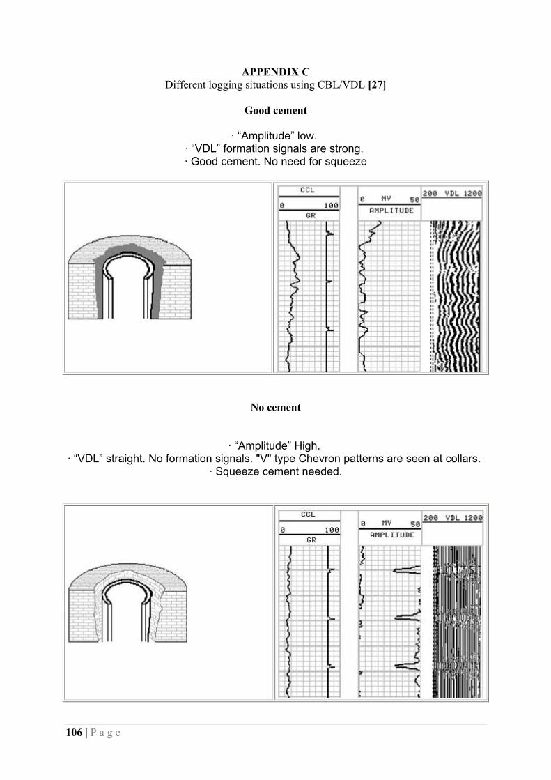
106 | P a g e
APPENDIX C Different logging situations using CBL/VDL [27]
Good cement
· “Amplitude” low.
· “VDL” formation signals are strong. · Good cement. No need for squeeze
No cement
· “Amplitude” High. · “VDL” straight. No formation signals. "V" type Chevron patterns are seen at collars.
· Squeeze cement needed.

107 | P a g e
Partial cement
“Amplitude” is low and moderate. · “VDL” can shows both wiggly formation signals and straight casing signals
· Squeeze can be necessary if the channel is long enough..
Micro annulus
· “Amplitude” is moderate.. · “VDL” can shows both wiggly formation signals and straight casing signals
·In case of doubt, repeat the log under 1000psi pressure to the well. The gap will be closed and log will change to "Good Cement"
· No need for squeeze..

108 | P a g e
Cement without bond to formation
Amplitude” low. · “VDL” doesn't show casing and formation signals. Thin mud signals are visible
· Squeeze needed
Note: Keep in mind that gas in formation can give the same model.
Cement bond in hard formations
Amplitude changes between low and high · Formation signals cover casing signals. · No need for cement...

109 | P a g e
APPENDIX D Cleaning criteria when abandoning platform [3]

110 | P a g e
APPENDIX E
Category A, riser less open water system [55]

111 | P a g e
APPENDIX F
Category B: open water system with work-over riser [55]

112 | P a g e
APPENDIX G
Category C: landing string system inside marine riser [55]

113 | P a g e
APPENDIX H
Typical well completion TOGI [51]

114 | P a g e
APPENDIX I
Well status when arriving TOGI [51]
Lower DHSV closed with 140 bar trapped below
Upper DHSV closed with 110 bar below
Production master valve closed with 100 bar below
Production swab valve closed with 35 bar below
Production bore filled with Methanol from lower DHSV to production swab valve
Annulus production valve closed with 1,2 sg hydrostatic column
Annulus swab valve closed
X-mas tree cap installed
TOC behind 9 5/8 casing estimated at 1097,5 m MD
Differential pressure and old mud behind casings

115 | P a g e
APPENDIX J
Cement composition [67]