Embed Size (px)
Citation preview

Masterpact Schneider Electric90
Masterpact Schneider Electric91
Installation recommendations
Presentation 1Functions and characteristics 9Dimensions and connection 53Electrical diagrams 81
Operating conditions 92Installation in switchboard 94Door interlock catch 96Cable-type door interlock 97Connection of MN, MX and XF voltage releases 97Power connection 98Recommended busbars drilling 100Busbar sizing 102Temperature derating 104Power dissipation and input/output resistance 104Derating in switchboards 105Substitution kit 112
Additional characteristics 115References 121
Masterpact
Masterpact Schneider Electric92
Installationrecommendations
E51
261B
Test
E51
262B
Test
E51
260B
Test
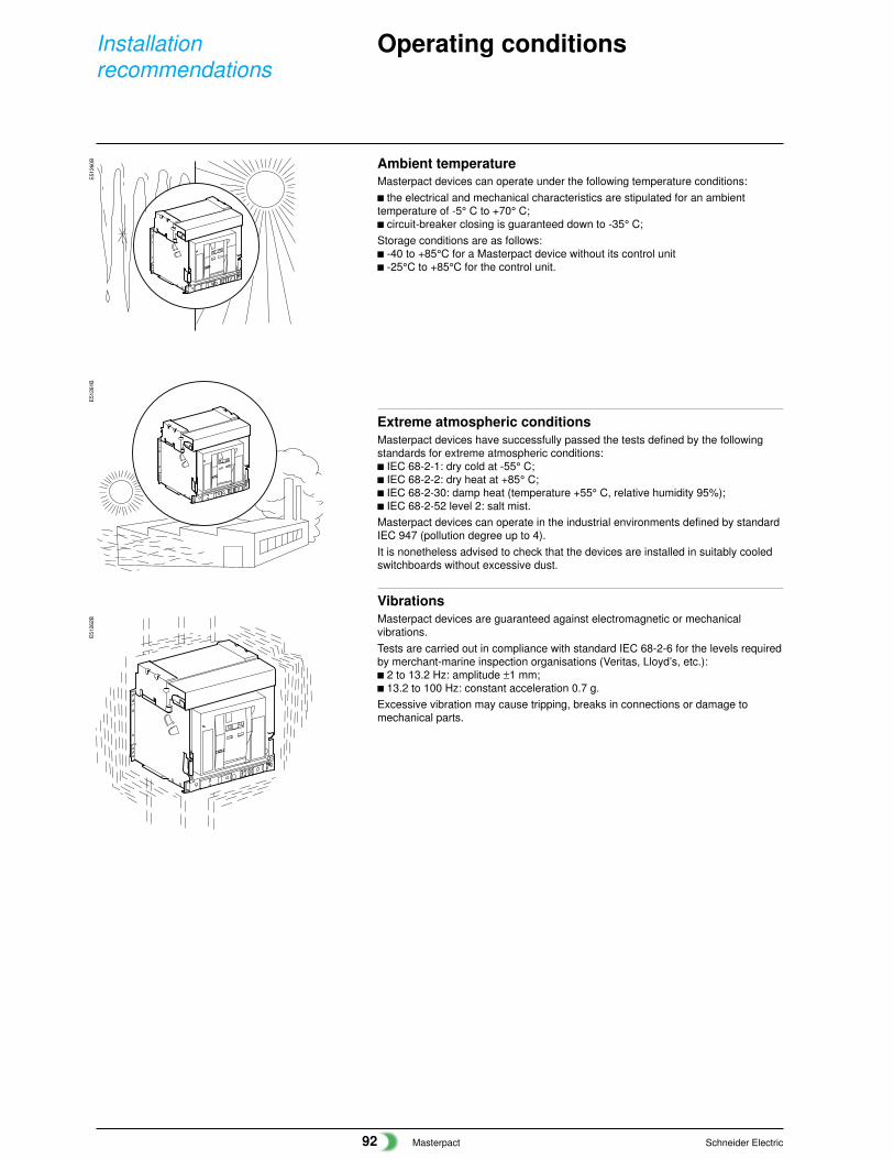
Ambient temperatureMasterpact devices can operate under the following temperature conditions:c the electrical and mechanical characteristics are stipulated for an ambienttemperature of -5° C to +70° C;c circuit-breaker closing is guaranteed down to -35° C;Storage conditions are as follows:c -40 to +85°C for a Masterpact device without its control unitc -25°C to +85°C for the control unit.
Extreme atmospheric conditionsMasterpact devices have successfully passed the tests defined by the followingstandards for extreme atmospheric conditions:c IEC 68-2-1: dry cold at -55° C;c IEC 68-2-2: dry heat at +85° C;c IEC 68-2-30: damp heat (temperature +55° C, relative humidity 95%);c IEC 68-2-52 level 2: salt mist.Masterpact devices can operate in the industrial environments defined by standardIEC 947 (pollution degree up to 4).It is nonetheless advised to check that the devices are installed in suitably cooledswitchboards without excessive dust.
VibrationsMasterpact devices are guaranteed against electromagnetic or mechanicalvibrations.Tests are carried out in compliance with standard IEC 68-2-6 for the levels requiredby merchant-marine inspection organisations (Veritas, Lloyd’s, etc.):c 2 to 13.2 Hz: amplitude ±1 mm;c 13.2 to 100 Hz: constant acceleration 0.7 g.Excessive vibration may cause tripping, breaks in connections or damage tomechanical parts.
Operating conditions
Masterpact Schneider Electric93
E51
263B
2000
m
Test
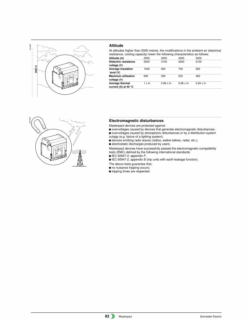
AltitudeAt altitudes higher than 2000 metres, the modifications in the ambient air (electricalresistance, cooling capacity) lower the following characteristics as follows:Altitude (m) 2000 3000 4000 5000Dielectric resistance 3500 3150 2500 2100voltage (V)Average insulation 1000 900 700 600 level (V)Maximum utilisation 690 590 520 460voltage (V)Average thermal 1 x In 0.99 x In 0.96 x In 0.94 x Incurrent (A) at 40 °C
E51
264B
Test
Electromagnetic disturbancesMasterpact devices are protected against:c overvoltages caused by devices that generate electromagnetic disturbances;c overvoltages caused by atmospheric disturbances or by a distribution-systemoutage (e.g. failure of a lighting system);c devices emitting radio waves (radios, walkie-talkies, radar, etc.);c electrostatic discharges produced by users.Masterpact devices have successfully passed the electromagnetic-compatibilitytests (EMC) defined by the following international standards:c IEC 60947-2, appendix F;c IEC 60947-2, appendix B (trip units with earth-leakage function).The above tests guarantee that:c no nuisance tripping occurs;c tripping times are respected.
Masterpact Schneider Electric94
Installationrecommendations
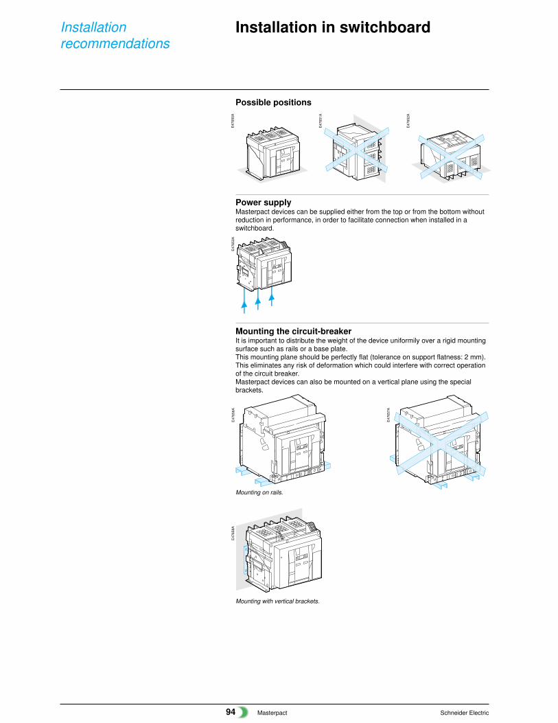
Possible positions
Power supplyMasterpact devices can be supplied either from the top or from the bottom withoutreduction in performance, in order to facilitate connection when installed in aswitchboard.
Installation in switchboard
Mounting the circuit-breakerIt is important to distribute the weight of the device uniformily over a rigid mountingsurface such as rails or a base plate.This mounting plane should be perfectly flat (tolerance on support flatness: 2 mm).This eliminates any risk of deformation which could interfere with correct operationof the circuit breaker.Masterpact devices can also be mounted on a vertical plane using the specialbrackets.
E47
656A
E47
657A
E47
658A
E47
650A
E47
651A
E47
652A
E47
653A
Mounting with vertical brackets.
Mounting on rails.
Masterpact Schneider Electric95
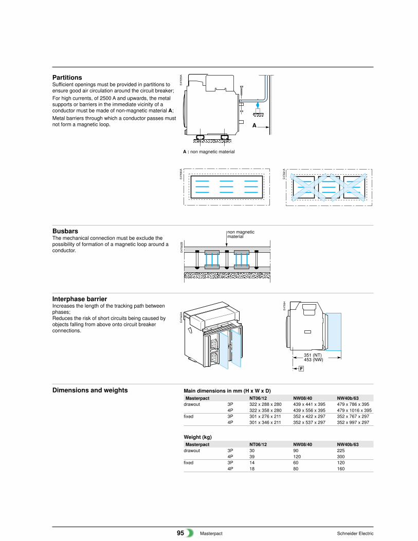
PartitionsSufficient openings must be provided in partitions toensure good air circulation around the circuit breaker;For high currents, of 2500 A and upwards, the metalsupports or barriers in the immediate vicinity of aconductor must be made of non-magnetic material A;Metal barriers through which a conductor passes mustnot form a magnetic loop.
A : non magnetic material
BusbarsThe mechanical connection must be exclude thepossibility of formation of a magnetic loop around aconductor.
E47
659A
non magneticmaterial
E47
660A
E47
661A
E47
662B
A
E47
663A
F
351 (NT)453 (NW)
E47
664
Interphase barrierIncreases the length of the tracking path betweenphases;Reduces the risk of short circuits being caused byobjects falling from above onto circuit breakerconnections.
Dimensions and weights Main dimensions in mm (H x W x D)Masterpact NT06/12 NW08/40 NW40b/63
drawout 3P 322 x 288 x 280 439 x 441 x 395 479 x 786 x 3954P 322 x 358 x 280 439 x 556 x 395 479 x 1016 x 395
fixed 3P 301 x 276 x 211 352 x 422 x 297 352 x 767 x 2974P 301 x 346 x 211 352 x 537 x 297 352 x 997 x 297
Weight (kg)Masterpact NT06/12 NW08/40 NW40b/63
drawout 3P 30 90 2254P 39 120 300
fixed 3P 14 60 1204P 18 80 160
Masterpact Schneider Electric96
Installationrecommendations
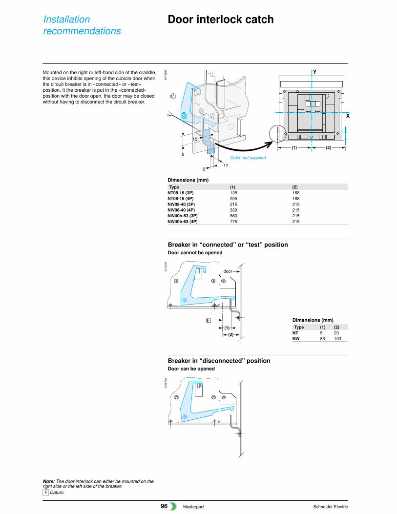
Note: The door interlock can either be mounted on theright side or the left side of the breaker.F Datum.
Breaker in “connected” or “test” positionDoor cannot be opened
Breaker in “disconnected” positionDoor can be opened
Dimensions (mm)Type (1) (2)
NT08-16 (3P) 135 168NT08-16 (4P) 205 168NW08-40 (3P) 215 215NW08-40 (4P) 330 215NW40b-63 (3P) 660 215NW40b-63 (4P) 775 215
17
8
5
15
X
Y
(2) (1)
(1)
F
(2)
door
E47
669B
E47
670A
E47
671A
Dimensions (mm)Type (1) (2)
NT 5 23NW 83 103
Catch not supplied
Door interlock catch
Mounted on the right or left-hand side of the craddle,this device inhibits opening of the cubicle door whenthe circuit breaker is in «connected» or «test»position. It the breaker is put in the «connected»position with the door open, the door may be closedwithout having to disconnect the circuit breaker.

Masterpact Schneider Electric97
Cable-type door interlockConnection of MN, MX and XFvoltage releases
NT/NWCable-type door interlockThis option prevents door opening when the circuit breaker is closed and preventscircuit breaker closing when the door is open.For this, a special plate associated with a lock and a cable is mounted on the rightside of the circuit breaker.With this interlock installed, the source changeover function cannot beimplemented.
Wiring of voltage releasesDuring pick-up, the power consumed is approximately 150 to 200 VA. For lowcontrol voltages (12, 24, 48 V), maximum cable lengths are imposed by the voltageand the cross-sectional area of cables.Recommanded maximum cable lengths (meter)
12 V 24 V 48 V2,5 mm2 1,5 mm2 2,5 mm2 1,5 mm2 2,5 mm2 1,5 mm2
MN U source 100 % – – 58 35 280 165U source 85 % – – 16 10 75 45
MX-XF U source 100 % 21 12 115 70 550 330U source 85 % 10 6 75 44 350 210
Note: the indicated length is that of each of the two wires
121
84
10
165
46
79 52
E59
113A
E59
114B
E59
115A
Masterpact Schneider Electric98
Installationrecommendations
Power connection
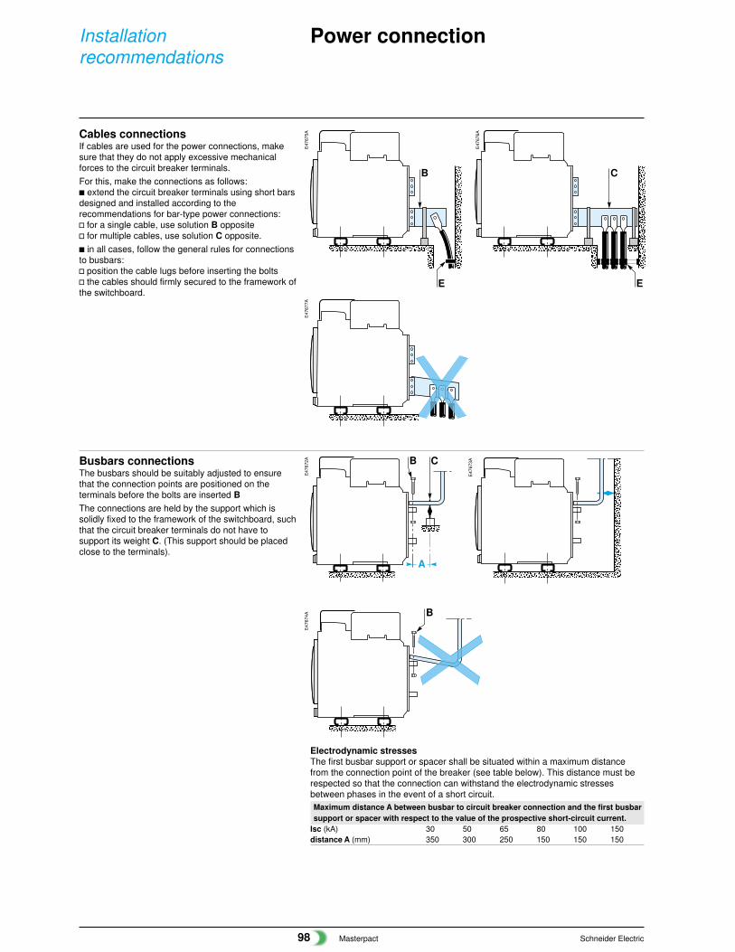
Busbars connectionsThe busbars should be suitably adjusted to ensurethat the connection points are positioned on theterminals before the bolts are inserted BThe connections are held by the support which issolidly fixed to the framework of the switchboard, suchthat the circuit breaker terminals do not have tosupport its weight C. (This support should be placedclose to the terminals).
Cables connectionsIf cables are used for the power connections, makesure that they do not apply excessive mechanicalforces to the circuit breaker terminals.For this, make the connections as follows:c extend the circuit breaker terminals using short barsdesigned and installed according to therecommendations for bar-type power connections:v for a single cable, use solution B oppositev for multiple cables, use solution C opposite.c in all cases, follow the general rules for connectionsto busbars:v position the cable lugs before inserting the boltsv the cables should firmly secured to the framework ofthe switchboard.
E47
672A
A
B C
B
B
E
C
E
E47
673A
E47
674A
E47
675A
E47
676A
E47
677A
Electrodynamic stressesThe first busbar support or spacer shall be situated within a maximum distancefrom the connection point of the breaker (see table below). This distance must berespected so that the connection can withstand the electrodynamic stressesbetween phases in the event of a short circuit.Maximum distance A between busbar to circuit breaker connection and the first busbarsupport or spacer with respect to the value of the prospective short-circuit current.
Isc (kA) 30 50 65 80 100 150distance A (mm) 350 300 250 150 150 150

Masterpact Schneider Electric99
ClampingCorrect clamping of busbars depends amongst other things, on the tighteningtorques used for the nuts and bolts. Over-tightening may have the sameconsequences as under-tightening.For connecting busbars (Cu ETP-NFA51-100) to the circuit breaker, the tighteningtorques to be used are shown in the table below.These values are for use with copper busbars and steel nuts and bolts, class 8.8.The same torques can be used with AGS-T52 quality aluminium bars (Frenchstandard NFA 02-104 or American National Standard H-35-1).
Tightening torquesØ Ø tightening torque (Nm) with contactnominal (mm) drilling (mm) with grower or or corrugatec
flat washers washers10 11 37.5 50
Busbar drillingExamples
Isolation distance
Busbar bendingWhen bending busbars maintain the radius indicated below(a smaller radius wouldcause cracks).
4 532
6
1
e
r
X
Dimensions (mm)e radius of curvature r
min recommended5 5 7.510 15 18 to 20
E47
678A
E47
679A
E47
680A
E47
667B
E47
668
Examples
E47
665
1 terminal screw factory-tightened to 16 Nm (NW), 13 Nm (NT)2 breaker terminal3 busbar4 bolt5 washer6 nut
E47
329A
E47
330A
E47
331A
Dimensions (mm)Ui X min
600 V 8 mm1000 V 14 mm
Masterpact Schneider Electric100
Installationrecommendations
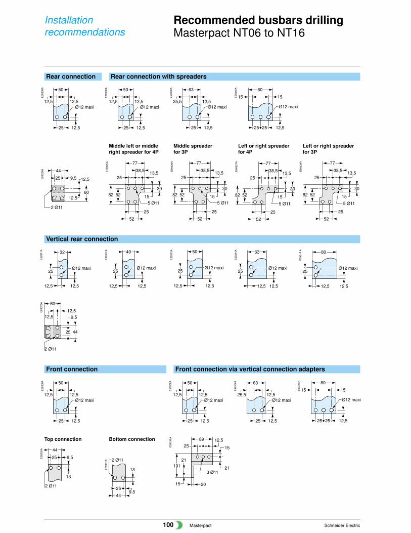
Recommended busbars drillingMasterpact NT06 to NT16
Rear connection Rear connection with spreaders
Vertical rear connection
E59
324A
2 Ø11
25 9,5
44
12,560
12,5
52
5 Ø11
13,5=25 =
38,5
77
15
305282
25
13,5=25 =
38,5
77
5282 15
30
25
52
5 Ø11 5 Ø11
13,5=25 =
38,5
77
15
305282
25
52
25
9,5
44
12,5
60
12,5
2 Ø11
25 9,5
44
13
2 Ø11
3 Ø11
12,5=25 =
89
15
21
20
10121
15
5 Ø11
13,5=25 =
38,5
77
15
305282
25
52
E59
325A
E59
326A
E59
327A
E59
328A
E59
329A
Front connection Front connection via vertical connection adapters
E59
330A
E59
332A
Middle left or middle Middle spreader Left or right spreader Left or right spreaderright spreader for 4P for 3P for 4P for 3P
12,5Ø12 maxi
25 12,5
50
12,5 12,5Ø12 maxi
25 12,5
50
12,5 25,5Ø12 maxi
25 12,5
63
12,515
Ø12 maxi
25 12,5
80
25
15E59
308A
E59
308A
E59
309A
E59
310A
Ø12 maxi
12,5
32
25
12,5
Ø12 maxi
12,5
40
25
12,5
Ø12 maxi
12,5
50
25
12,5
Ø12 maxi
12,5
63
25
12,5
Ø12 maxi
12,5
80
25
12,5
E59
311A
E59
312A
E59
313A
E59
314A
E59
315
A
12,5Ø12 maxi
25 12,5
50
12,5 25,5Ø12 maxi
25 12,5
63
12,512,5Ø12 maxi
25 12,5
50
12,515
Ø12 maxi
25 12,5
80
25
15E59
308A
E59
308A
E59
309A
E59
310A
9,525
44
13
2 Ø11
E59
331A
Top connection Bottom connection
Masterpact Schneider Electric101
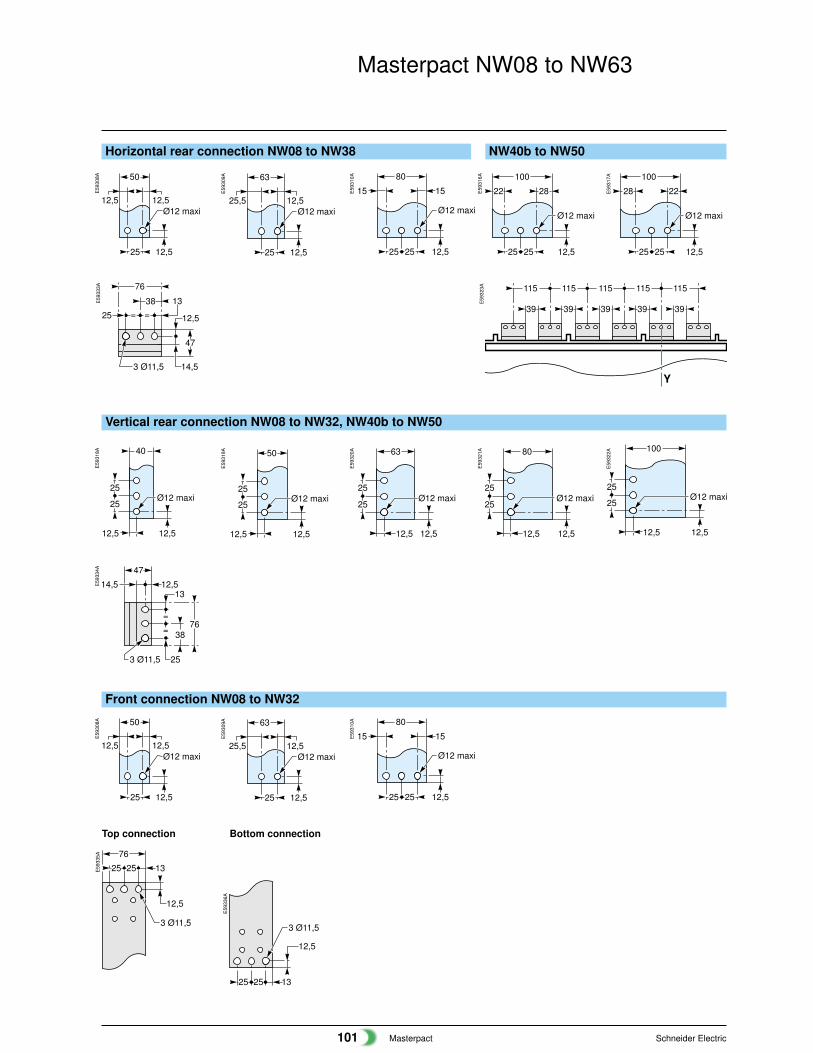
Horizontal rear connection NW08 to NW38 NW40b to NW50
==
76
13
25
3 Ø11,5
12,5
38
47
14,5Y
115115115115115
3939 39 39 39
76
253 Ø11,5
38
12,513
47
14,5
=
=
12,5
25 25 13
3 Ø11,5
76
Masterpact NW08 to NW63
Vertical rear connection NW08 to NW32, NW40b to NW50
Front connection NW08 to NW32
E59
333A
E59
323A
E59
334A
E59
335A
Top connection Bottom connection
12,5Ø12 maxi
25 12,5
50
12,5 25,5Ø12 maxi
25 12,5
63
12,515
Ø12 maxi
25 12,5
80
25
15 22
Ø12 maxi
25 12,5
100
25
28 28
Ø12 maxi
25 12,5
100
25
22
Ø12 maxi
12,5
40
25
12,5
25Ø12 maxi
12,5
50
25
12,5
25Ø12 maxi
12,5
63
25
12,5
25Ø12 maxi
12,5
80
25
12,5
25Ø12 maxi
12,5
100
25
12,5
25
E59
308A
E59
309A
E59
310A
E59
316A
E59
317A
E59
318A
E59
319A
E59
320A
E59
321A
E59
322A
12,5Ø12 maxi
25 12,5
50
12,5 25,5Ø12 maxi
25 12,5
63
12,515
Ø12 maxi
25 12,5
80
25
15E59
308A
E59
309A
E59
310A
12,5
1325 25
3 Ø11,5
E59
336A
Masterpact Schneider Electric102
Installationrecommendations
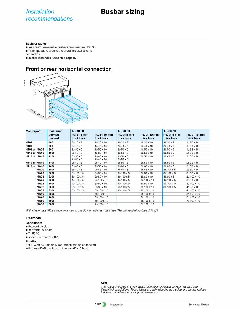
Busbar sizing
Basis of tables:c maximum permissible busbars temperature: 100 °Cc Ti: temperature around the circuit breaker and itsconnectionc busbar material is unpainted copper.
Masterpact maximum Ti : 40 °C Ti : 50 °C Ti : 60 °Cservice no. of 5 mm no. of 10 mm no. of 5 mm no. of 10 mm no. of 5 mm no. of 10 mmcurrent thick bars thick bars thick bars thick bars thick bars thick bars
NT06 400 2b.30 x 5 1b.30 x 10 2b.30 x 5 1b.30 x 10 2b.30 x 5 1b.30 x 10NT06 630 2b.40 x 5 1b.40 x 10 2b.40 x 5 1b.40 x 10 2b.40 x 5 1b.40 x 10NT08 or NW08 800 2b.50 x 5 1b.50 x 10 2b.50 x 5 1b.50 x 10 2b.50 x 5 1b.63 x 10NT10 or NW10 1000 3b.50 x 5 1b.63 x 10 3b.50 x 5 2b.50 x 10 3b.63 x 5 2b.50 x 10NT12 or NW12 1250 3b.50 x 5 2b.40 x 10 3b.50 x 5 2b.50 x 10 3b.63 x 5 2b.50 x 10
2b.80 x 5 2b.40 x 10 2b.80 x 5NT16 or NW16 1400 3b.50 x 5 2b.40 x 10 2b.80 x 5 2b.50 x 10 3b.80 x 5 2b.63 x 10NT16 or NW16 1600 3b.63 x 5 2b.50 x 10 3b.80 x 5 2b.63 x 10 3b.80 x 5 3b.50 x 10
NW20 1800 3b.80 x 5 2b.63 x 10 3b.80 x 5 2b.63 x 10 3b.100 x 5 2b.80 x 10NW20 2000 3b.100 x 5 2b.80 x 10 3b.100 x 5 2b.80 x 10 3b.100 x 5 3b.63 x 10NW25 2200 3b.100 x 5 2b.80 x 10 3b.100 x 5 2b.80 x 10 4b.80 x 5 2b.100 x 10NW25 2500 4b.100 x 5 2b.100 x 10 4b.100 x 5 2b.100 x 10 4b.100 x 5 3b.80 x 10NW32 2800 4b.100 x 5 3b.80 x 10 4b.100 x 5 3b.80 x 10 5b.100 x 5 3b.100 x 10NW32 3000 5b.100 x 5 3b.80 x 10 6b.100 x 5 3b.100 x 10 8b.100 x 5 4b.80 x 10NW32 3200 6b.100 x 5 3b.100 x 10 8b.100 x 5 3b.100 x 10 4b.100 x 10NW40 3800 4b.100 x 10 5b.100 x 10 5b.100 x 10NW40 4000 5b.100 x 10 5b.100 x 10 6b.100 x 10NW50 4500 6b.100 x 10 6b.100 x 10 7b.100 x 10NW50 5000 7b.100 x 10 7b.100 x 10
E47
681A
ExampleConditions:c drawout versionc horizontal busbarsc Ti: 50 °Cc service current: 1800 A.Solution:For Ti = 50 °C, use an NW20 which can be connectedwith three 80x5 mm bars or two mm 63x10 bars.
Front or rear horizontal connection
NoteThe values indicated in these tables have been extrapolated from test data andtheoretical calculations. These tables are only intended as a guide and cannot replaceindustrial experience or a temperature rise test.
With Masterpact NT, it is recommanded to use 50 mm wideness bars (see "Recommended busbars drilling")
Masterpact Schneider Electric103
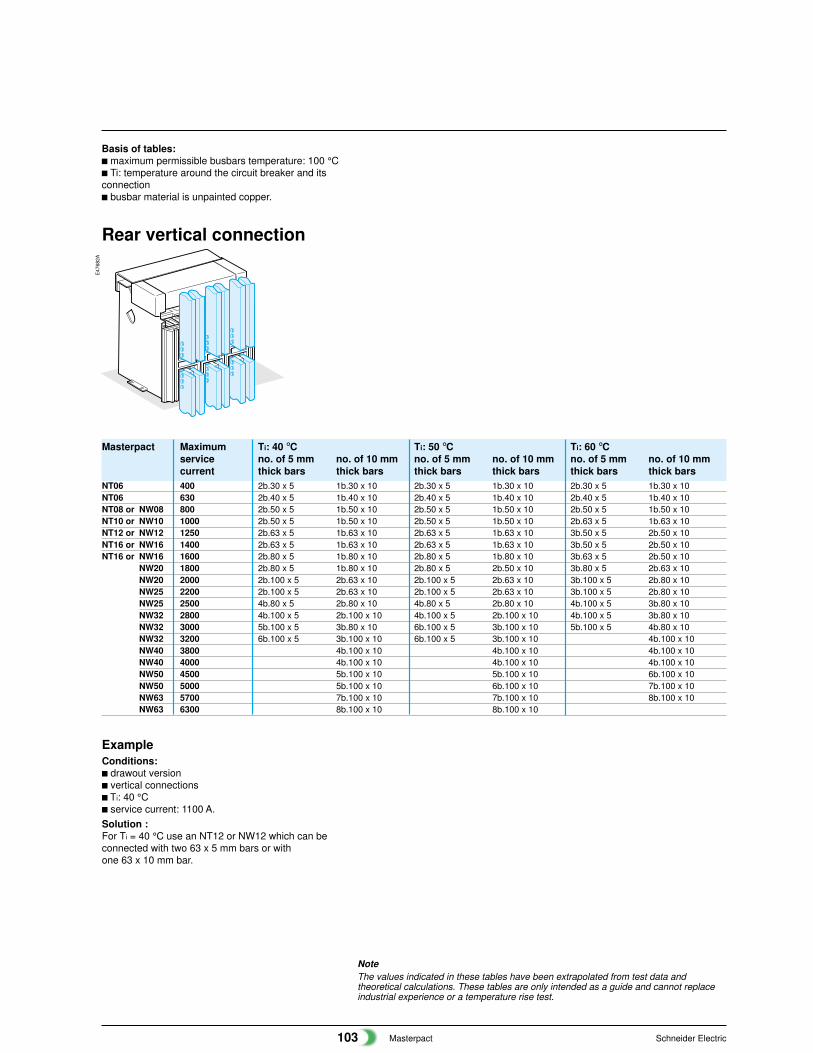
Masterpact Maximum Ti: 40 °C Ti: 50 °C Ti: 60 °Cservice no. of 5 mm no. of 10 mm no. of 5 mm no. of 10 mm no. of 5 mm no. of 10 mmcurrent thick bars thick bars thick bars thick bars thick bars thick bars
NT06 400 2b.30 x 5 1b.30 x 10 2b.30 x 5 1b.30 x 10 2b.30 x 5 1b.30 x 10NT06 630 2b.40 x 5 1b.40 x 10 2b.40 x 5 1b.40 x 10 2b.40 x 5 1b.40 x 10NT08 or NW08 800 2b.50 x 5 1b.50 x 10 2b.50 x 5 1b.50 x 10 2b.50 x 5 1b.50 x 10NT10 or NW10 1000 2b.50 x 5 1b.50 x 10 2b.50 x 5 1b.50 x 10 2b.63 x 5 1b.63 x 10NT12 or NW12 1250 2b.63 x 5 1b.63 x 10 2b.63 x 5 1b.63 x 10 3b.50 x 5 2b.50 x 10NT16 or NW16 1400 2b.63 x 5 1b.63 x 10 2b.63 x 5 1b.63 x 10 3b.50 x 5 2b.50 x 10NT16 or NW16 1600 2b.80 x 5 1b.80 x 10 2b.80 x 5 1b.80 x 10 3b.63 x 5 2b.50 x 10
NW20 1800 2b.80 x 5 1b.80 x 10 2b.80 x 5 2b.50 x 10 3b.80 x 5 2b.63 x 10NW20 2000 2b.100 x 5 2b.63 x 10 2b.100 x 5 2b.63 x 10 3b.100 x 5 2b.80 x 10NW25 2200 2b.100 x 5 2b.63 x 10 2b.100 x 5 2b.63 x 10 3b.100 x 5 2b.80 x 10NW25 2500 4b.80 x 5 2b.80 x 10 4b.80 x 5 2b.80 x 10 4b.100 x 5 3b.80 x 10NW32 2800 4b.100 x 5 2b.100 x 10 4b.100 x 5 2b.100 x 10 4b.100 x 5 3b.80 x 10NW32 3000 5b.100 x 5 3b.80 x 10 6b.100 x 5 3b.100 x 10 5b.100 x 5 4b.80 x 10NW32 3200 6b.100 x 5 3b.100 x 10 6b.100 x 5 3b.100 x 10 4b.100 x 10NW40 3800 4b.100 x 10 4b.100 x 10 4b.100 x 10NW40 4000 4b.100 x 10 4b.100 x 10 4b.100 x 10NW50 4500 5b.100 x 10 5b.100 x 10 6b.100 x 10NW50 5000 5b.100 x 10 6b.100 x 10 7b.100 x 10NW63 5700 7b.100 x 10 7b.100 x 10 8b.100 x 10NW63 6300 8b.100 x 10 8b.100 x 10
ExampleConditions:c drawout versionc vertical connectionsc Ti: 40 °Cc service current: 1100 A.Solution :For Ti = 40 °C use an NT12 or NW12 which can beconnected with two 63 x 5 mm bars or withone 63 x 10 mm bar.
E47
682A
Rear vertical connection
NoteThe values indicated in these tables have been extrapolated from test data andtheoretical calculations. These tables are only intended as a guide and cannot replaceindustrial experience or a temperature rise test.
Basis of tables:c maximum permissible busbars temperature: 100 °Cc Ti: temperature around the circuit breaker and itsconnectionc busbar material is unpainted copper.
Masterpact Schneider Electric104
Installationrecommendations
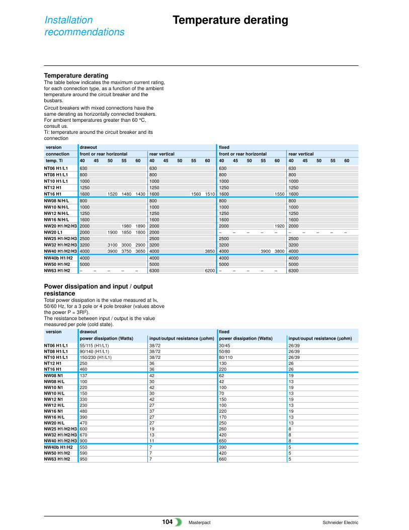
version drawout fixedpower dissipation (Watts) input/output resistance (µohm) power dissipation (Watts) input/ouput resistance (µohm)
NT06 H1/L1 55/115 (H1/L1) 38/72 30/45 26/39NT08 H1/L1 90/140 (H1/L1) 38/72 50/80 26/39NT10 H1/L1 150/230 (H1/L1) 38/72 80/110 26/39NT12 H1 250 36 130 26NT16 H1 460 36 220 26NW08 N1 137 42 62 19NW08 H/L 100 30 42 13NW10 N1 220 42 100 19NW10 H/L 150 30 70 13NW12 N1 330 42 150 19NW12 H/L 230 27 100 13NW16 N1 480 37 220 19NW16 H/L 390 27 170 13NW20 H/L 470 27 250 13NW25 H1/H2/H3 600 19 260 8NW32 H1/H2/H3 670 13 420 8NW40 H1/H2/H3 900 11 650 8NW40b H1/H2 550 7 390 5NW50 H1/H2 590 7 420 5NW63 H1/H2 950 7 660 5
Temperature derating
Temperature deratingThe table below indicates the maximum current rating,for each connection type, as a function of the ambienttemperature around the circuit breaker and thebusbars.Circuit breakers with mixed connections have thesame derating as horizontally connected breakers.For ambient temperatures greater than 60 °C,consult us.Ti: temperature around the circuit breaker and itsconnection
Power dissipation and input / outputresistanceTotal power dissipation is the value measured at IN,50/60 Hz, for a 3 pole or 4 pole breaker (values abovethe power P = 3RI2).The resistance between input / output is the valuemeasured per pole (cold state).
version drawout fixedconnection front or rear horizontal rear vertical front or rear horizontal rear verticaltemp. Ti 40 45 50 55 60 40 45 50 55 60 40 45 50 55 60 40 45 50 55 60
NT06 H1/L1 630 630 630 630NT08 H1/L1 800 800 800 800NT10 H1/L1 1000 1000 1000 1000NT12 H1 1250 1250 1250 1250NT16 H1 1600 1520 1480 1430 1600 1560 1510 1600 1550 1600NW08 N/H/L 800 800 800 800NW10 N/H/L 1000 1000 1000 1000NW12 N/H/L 1250 1250 1250 1250NW16 N/H/L 1600 1600 1600 1600NW20 H1/H2/H3 2000 1980 1890 2000 2000 1920 2000NW20 L1 2000 1900 1850 1800 2000 – – – – – – – – – –NW25 H1/H2/H3 2500 2500 2500 2500NW32 H1/H2/H3 3200 3100 3000 2900 3200 3200 3200NW40 H1/H2/H3 4000 3900 3750 3650 4000 3850 4000 3900 3800 4000NW40b H1/H2 4000 4000 4000 4000NW50 H1/H2 5000 5000 5000 5000NW63 H1/H2 – – – – – 6300 6200 – – – – – 6300

Masterpact Schneider Electric105
Factors affecting switchboard designThe temperature around the circuit breaker and itsconnections:This is used to define the type of circuit breaker to beused and its connection arrangement.Vents at the top and bottom of the cubicles:Vents considerably reduce the temperature inside theswitchboard, but must be designed so as to respectthe degree of protection provided by the enclosure.For weatherproof heavy-duty cubicles, a forcedventilation system may be required.The heat dissipated by the devices installed in theswitchboard:This is the heat dissipated by the circuit breakersunder normal conditions (service current).The size of the enclosure:This determines the volume for cooling calculations.Switchboard installation mode:Free-standing, against a wall, etc.Horizontal partitions:Partitions can obstruct air circulation within theenclosure.
Derating in switchboard
NoteThe values indicated in these tables have been extrapolated from test data andtheoretical calculations. These tables are only intended as a guide and cannot replaceindustrial experience or a temperature rise test.
Masterpact NT06-16 H1/L1 (switchboard 2000 x 400 x 400 mm)Type NT06 H1/L1 NT08 H1/L1 NT10 H1/L1 NT12 H1 NT16 H1
4 H1/L1 H1/L13 630 630 800 800 1000/1000 1000/1000 1250 1250 1400 15202143 630 630 800 800 1000/950 1000/1000 1250 1250 1330 14402143 630 630 800 800 1000/890 1000/960 1200 1250 1250 134021
43 630 630 800 800 1000/960 1000/1000 1250 1250 1330 14002143 630 630 800 800 1000/910 1000/980 1220 1250 1260 13302143 630 630 800 800 1000/860 1000/930 1150 1230 1200 126021
Switchboard composition
Connection type
Busbar dimensions (mm)
Ventilated switchboard(� IP31)
Ta = 35°C
Ta = 45°C
Ta = 55°C
Non ventilatedswitchboard (� IP54)
Ta = 35°C
Ta = 45°C
Ta = 55°C
4321
2b. 40x5 2b. 50x5 3b. 63x52b. 63x5
3b. 63x53b. 50x5
3b. 80x53b. 63x5
Basis of tablesc switchboard dimensionsc number of circuit-breakers installedc type of breaker connectionsc drawout versionsc ambient temperature outside of the switchboard: Ta
(IEC 60439-1).
2000
400400
2000
400400
E47
710A
E47
709A
Masterpact Schneider Electric106
Installationrecommendations
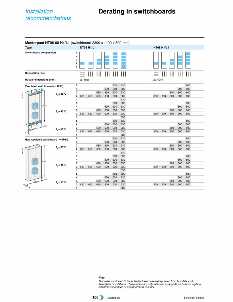
Derating in switchboards
Masterpact NT06-08 H1/L1 (switchboard 2300 x 1100 x 500 mm)Type NT06 H1/L1 NT08 H1/L1
5 630 630 8004 630 630 630 800 8003 630 630 630 630 800 800 8002 630 630 630 630 630 630 800 800 800 800 8001 6305 630 630 8004 630 630 630 800 8003 630 630 630 630 800 800 8002 630 630 630 630 630 630 800 800 800 800 8001 6305 630 630 8004 630 630 630 800 8003 630 630 630 630 800 800 8002 630 630 630 630 630 630 800 800 800 800 8001 6305 630 630 8004 630 630 630 800 8003 630 630 630 630 800 800 8002 630 630 630 630 630 630 800 800 800 800 8001 6305 630 630 8004 630 630 630 800 8003 630 630 630 630 800 800 8002 630 630 630 630 630 630 800 800 800 800 8001 6305 630 630 8004 630 630 630 800 8003 630 630 630 630 800 800 8002 630 630 630 630 630 630 800 800 800 800 8001 630
500
600
2300
200
300
500
600
2300
200
300
E47
712B
E47
711B
54321
NoteThe values indicated in these tables have been extrapolated from test data andtheoretical calculations. These tables are only intended as a guide and cannot replaceindustrial experience or a temperature rise test.
Switchboard composition
Connection type
Busbar dimensions (mm)
Ventilated switchboard (� IP31)
Ta = 35°C
Ta = 45°C
Ta = 55°C
Non ventilated switchboard (� IP54)
Ta = 35°C
Ta = 45°C
Ta = 55°C
2b. 40x5 2b. 50x5
Masterpact Schneider Electric107
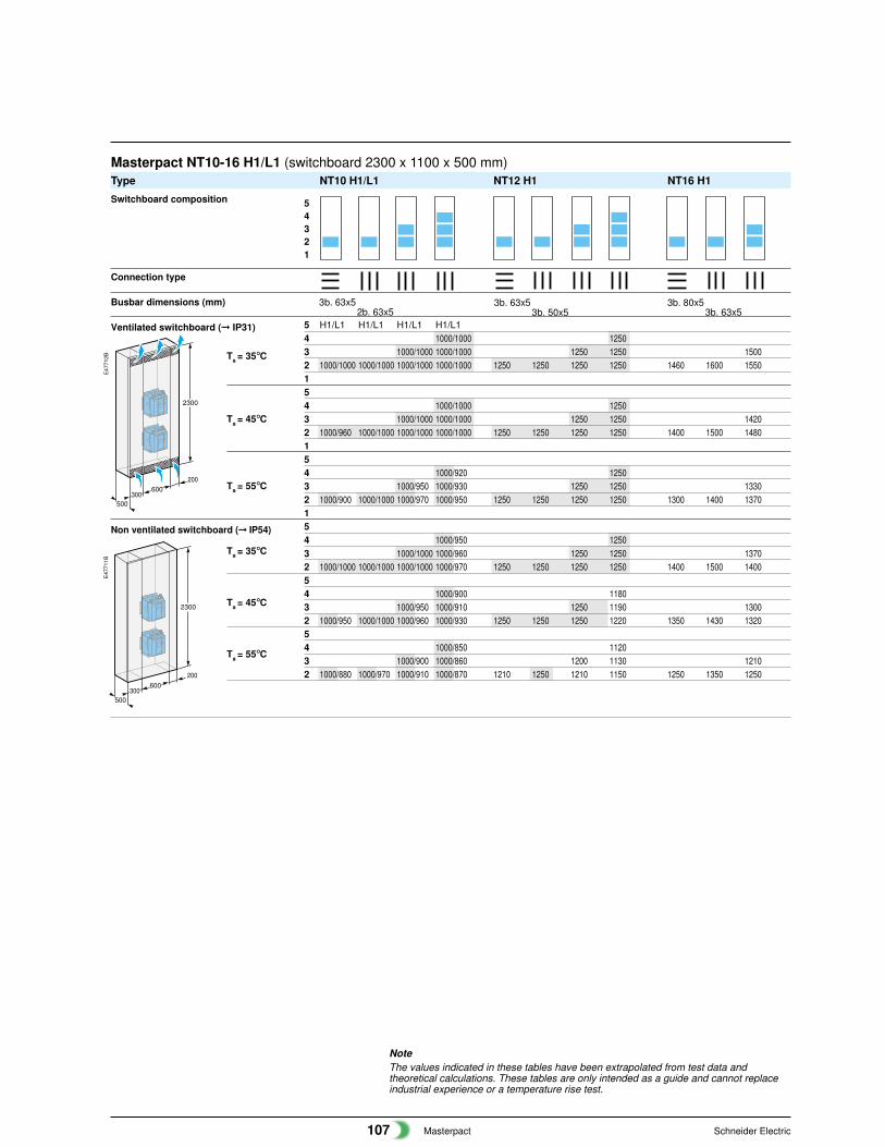
NoteThe values indicated in these tables have been extrapolated from test data andtheoretical calculations. These tables are only intended as a guide and cannot replaceindustrial experience or a temperature rise test.
Masterpact NT10-16 H1/L1 (switchboard 2300 x 1100 x 500 mm)Type NT10 H1/L1 NT12 H1 NT16 H1
5 H1/L1 H1/L1 H1/L1 H1/L14 1000/1000 12503 1000/1000 1000/1000 1250 1250 15002 1000/1000 1000/1000 1000/1000 1000/1000 1250 1250 1250 1250 1460 1600 1550154 1000/1000 12503 1000/1000 1000/1000 1250 1250 14202 1000/960 1000/1000 1000/1000 1000/1000 1250 1250 1250 1250 1400 1500 1480154 1000/920 12503 1000/950 1000/930 1250 1250 13302 1000/900 1000/1000 1000/970 1000/950 1250 1250 1250 1250 1300 1400 1370154 1000/950 12503 1000/1000 1000/960 1250 1250 13702 1000/1000 1000/1000 1000/1000 1000/970 1250 1250 1250 1250 1400 1500 140054 1000/900 11803 1000/950 1000/910 1250 1190 13002 1000/950 1000/1000 1000/960 1000/930 1250 1250 1250 1220 1350 1430 132054 1000/850 11203 1000/900 1000/860 1200 1130 12102 1000/880 1000/970 1000/910 1000/870 1210 1250 1210 1150 1250 1350 1250
500
600
2300
200
300
500
600
2300
200
300
E47
712B
E47
711B
54321
Switchboard composition
Connection type
Busbar dimensions (mm)
Ventilated switchboard (� IP31)
Ta = 35°C
Ta = 45°C
Ta = 55°C
Non ventilated switchboard (� IP54)
Ta = 35°C
Ta = 45°C
Ta = 55°C
3b. 63x52b. 63x5
3b. 63x53b. 50x5
3b. 80x53b. 63x5
Masterpact Schneider Electric108
Installationrecommendations
Derating in switchboards
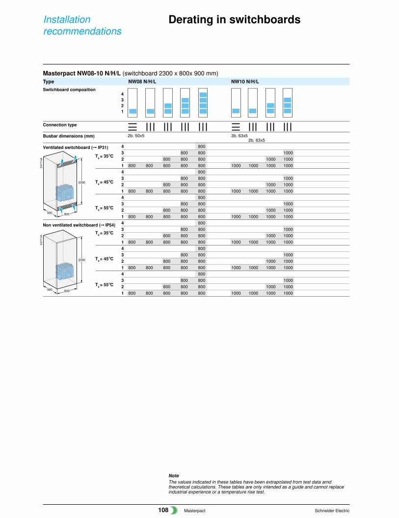
NoteThe values indicated in these tables have been extrapolated from test data arndtheoretical calculations. These tables are only intended as a guide and cannot replaceindustrial experience or a temperature rise test.
Masterpact NW08-10 N/H/L (switchboard 2300 x 800x 900 mm)Type NW08 N/H/L NW10 N/H/L
4 8003 800 800 10002 800 800 800 1000 10001 800 800 800 800 800 1000 1000 1000 10004 8003 800 800 10002 800 800 800 1000 10001 800 800 800 800 800 1000 1000 1000 10004 8003 800 800 10002 800 800 800 1000 10001 800 800 800 800 800 1000 1000 1000 10004 8003 800 800 10002 800 800 800 1000 10001 800 800 800 800 800 1000 1000 1000 10004 8003 800 800 10002 800 800 800 1000 10001 800 800 800 800 800 1000 1000 1000 10004 8003 800 800 10002 800 800 800 1000 10001 800 800 800 800 800 1000 1000 1000 1000
2300
800900
2300
800900
E47
714A
E47
713A
4321
Switchboard composition
Connection type
Busbar dimensions (mm)
Ventilated switchboard (� IP31)
Ta = 35°C
Ta = 45°C
Ta = 55°C
Non ventilated switchboard (� IP54)
Ta = 35°C
Ta = 45°C
Ta = 55°C
2b. 50x5 3b. 63x52b. 63x5
Masterpact Schneider Electric109
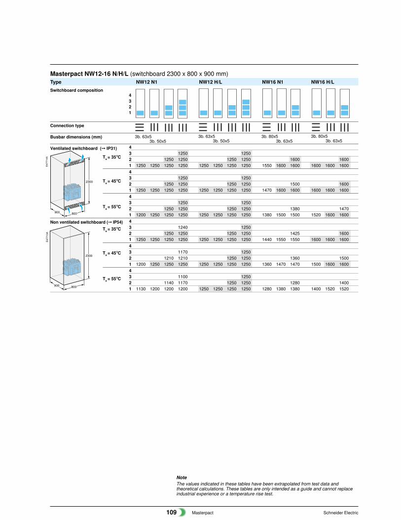
NoteThe values indicated in these tables have been extrapolated from test data andtheoretical calculations. These tables are only intended as a guide and cannot replaceindustrial experience or a temperature rise test.
Masterpact NW12-16 N/H/L (switchboard 2300 x 800 x 900 mm)Type NW12 N1 NW12 H/L NW16 N1 NW16 H/L
43 1250 12502 1250 1250 1250 1250 1600 16001 1250 1250 1250 1250 1250 1250 1250 1250 1550 1600 1600 1600 1600 160043 1250 12502 1250 1250 1250 1250 1500 16001 1250 1250 1250 1250 1250 1250 1250 1250 1470 1600 1600 1600 1600 160043 1250 12502 1250 1250 1250 1250 1380 14701 1200 1250 1250 1250 1250 1250 1250 1250 1380 1500 1500 1520 1600 160043 1240 12502 1250 1250 1250 1250 1425 16001 1250 1250 1250 1250 1250 1250 1250 1250 1440 1550 1550 1600 1600 160043 1170 12502 1210 1210 1250 1250 1360 15001 1200 1250 1250 1250 1250 1250 1250 1250 1360 1470 1470 1500 1600 160043 1100 12502 1140 1170 1250 1250 1280 14001 1130 1200 1200 1200 1250 1250 1250 1250 1280 1380 1380 1400 1520 1520
2300
800900
2300
800900
E47
714A
E47
713A
4321
Switchboard composition
Connection type
Busbar dimensions (mm)
Ventilated switchboard (� IP31)
Ta = 35°C
Ta = 45°C
Ta = 55°C
Non ventilated switchboard (� IP54)
Ta = 35°C
Ta = 45°C
Ta = 55°C
3b. 63x53b. 50x5
3b. 63x53b. 50x5
3b. 80x53b. 63x5
3b. 80x53b. 63x5
Masterpact Schneider Electric110
Installationrecommendations
Derating in switchboards
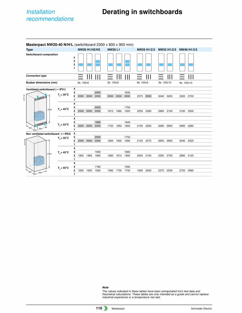
NoteThe values indicated in these tables have been extrapolated from test data andtheoretical calculations. These tables are only intended as a guide and cannot replaceindustrial experience or a temperature rise test.
Masterpact NW20-40 N/H/L (switchboard 2300 x 800 x 900 mm)Type NW20 H1/H2/H3 NW20 L1 NW25 H1/2/3 NW32 H1/2/3 NW40 H1/2/3
43 2000 18302 2000 2000 2000 2000 2000 2000 2375 2500 3040 3200 3320 3700143 2000 17502 2000 2000 2000 1810 1960 1920 2250 2380 2880 3100 3160 3500143 1880 16402 2000 2000 2000 1700 1850 1800 2100 2250 2690 2900 2960 3280143 2000 17502 2000 2000 2000 1800 1900 1890 2125 2275 2650 2850 3040 3320143 1900 16602 1900 1960 1960 1680 1810 1800 2000 2150 2550 2700 2880 3120143 1780 15502 1800 1920 1920 1590 1700 1700 1900 2020 2370 2530 2720 29601
2300
800900
2300
800900
E47
714A
E47
713A
4321
Switchboard composition
Connection type
Busbar dimensions (mm)
Ventilated switchboard (� IP31)
Ta = 35°C
Ta = 45°C
Ta = 55°C
Non ventilated switchboard (� IP54)
Ta = 35°C
Ta = 45°C
Ta = 55°C
3b. 100x5 3b. 100x5 4b. 100x5 3b. 100x10 4b. 100x10
Masterpact Schneider Electric111
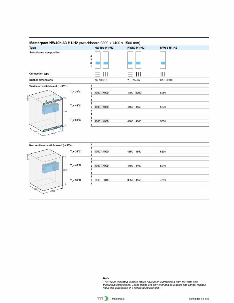
NoteThe values indicated in these tables have been extrapolated from test data andtheoretical calculations. These tables are only intended as a guide and cannot replaceindustrial experience or a temperature rise test.
Masterpact NW40b-63 H1/H2 (switchboard 2300 x 1400 x 1500 mm)Type NW40b H1/H2 NW50 H1/H2 NW63 H1/H2
432 4000 4000 4700 5000 60501432 4000 4000 4450 4850 56701432 4000 4000 4200 4600 53501
432 4000 4000 4350 4650 52901432 4000 4000 4100 4400 50401432 3840 3840 3850 4150 47301
Switchboard composition
Connection type
Busbar dimensions
Ventilated switchboard (� IP31)
Ta = 35°C
Ta = 45°C
Ta = 55°C
Non ventilated switchboard (� IP54)
Ta = 35°C
Ta = 45°C
Ta = 55°C
2300
14001500
2300
14001500
E47
716B
E47
715B
4321
5b. 100x10 7b. 100x10 8b. 100x10
Masterpact Schneider Electric112
Installationrecommendations
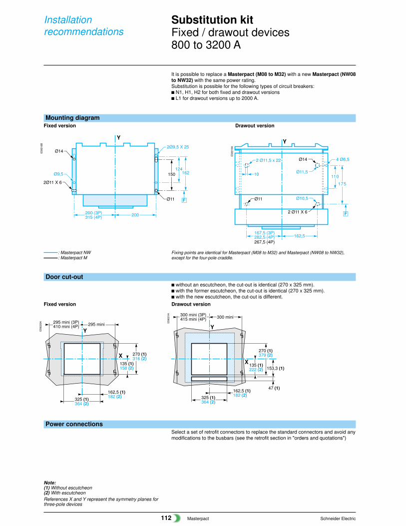
Substitution kitFixed / drawout devices800 to 3200 A
Mounting diagramFixed version Drawout version
Ø11,5
Ø10,5
2 Ø11,5 x 22
175
F
162,5167,5 (3P)282,5 (4P)
Y
11010
4 Ø6,5
2 Ø11 X 6
267,5 (4P)
Ø14
Ø11
Door cut-outc without an escutcheon, the cut-out is identical (270 x 325 mm).c with the former escutcheon, the cut-out is identical (270 x 325 mm).c with the new escutcheon, the cut-out is different.
Fixed version Drawout version
Y
X135 (1)158 (2)
270 (1)316 (2)
295 mini (3P)410 mini (4P) 295 mini
162,5 (1)182 (2)
325 (1)364 (2)
X
300 mini (3P)415 mini (4P)
Y
300 mini
135 (1)222 (2)
270 (1)379 (2)
153,3 (1)
47 (1)162,5 (1)182 (2)325 (1)
364 (2)
E59
220A E
5922
1A
Note:(1) Without escutcheon(2) With escutcheonReferences X and Y represent the symmetry planes forthree-pole devices
Fixing points are identical for Masterpact (M08 to M32) and Masterpact (NW08 to NW32),except for the four-pole craddle.
It is possible to replace a Masterpact (M08 to M32) with a new Masterpact (NW08to NW32) with the same power rating.Substitution is possible for the following types of circuit breakers:c N1, H1, H2 for both fixed and drawout versionsc L1 for drawout versions up to 2000 A.
E59
218B
E59
219A
Power connectionsSelect a set of retrofit connectors to replace the standard connectors and avoid anymodifications to the busbars (see the retrofit section in "orders and quotations")
Y
200
124162
F
2Ø9,5 X 25
200 (3P)315 (4P)
150
2Ø11 X 6
Ø9,5
Ø11
Ø14
: Masterpact NW: Masterpact M
Masterpact Schneider Electric113
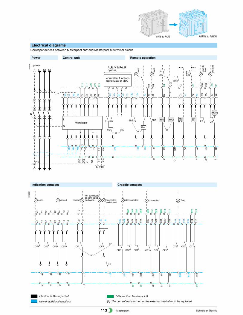
Indication contacts Craddle contacts
T4T3T2T1
Micrologic
Z4Z3Z2Z1
N L3L2L1
Q
Z5VN
V1
V2
V3
M3
M2
M1
F2+
F1
I
U
24 V DC
X2
X1
SG
2
SG
1
471
S1
474
484
S2Q
1
Q2
Q3
M2C M6C
181
182
184
SDE2
81
82 84
SDE1
K2
Res
K1
D2
D1
AT
MN MX2
C12
C11
MX1
C2
C3
C1
BPO
A2
A3
A1
BPF
XFPF
252
254
251
B1
MCH
B3
B2
CH
D1
C11 C1
A1
251
B1
81
82 84 D4 C12
C2
A4
252
254
262
B4
Z21
Z22
Z11
Z12
Z21
F2+
F1(1)
power
or
faul
t
faul
t
oror
read
y to
clos
e
char
ged
ALR, V, MR6, Roptions
equivalent functionsusing M2C or M6C
E59
217A
CT3
12 1411
22 2432 3431 21
OF4
42 4441
OF3 OF2 OF1
12 1422 2432 3442 44
1131 2141
OF . . OF
CE
. . 1
. . 2
. . 4
. . 6
. . 8
. . 5
EF . .
. . 2
. . 4
. . 1
912
911
934
932
931
CT2 CT1
924
922
921
914
374
372
371
331
332
334
CE3
321
322
324
CE2
311
312
314
CE1
334
332
324
322
314
312
331
321
311
822
824
821
812
814
811
832
834
831
CD3 CD2 CD1
362
364
352
354
361
351
closedopen closed connectedand closed
not connectedor connectedand open
or
Testconnecteddisconnected
E59
223A
M08 to M32 NW08 to NW32
Identical to Masterpact M
New or additional functions (1) The current transformer for the external neutral must be replaced
Different than Masterpact M
E59
222A
Electrical diagramsCorrespondences between Masterpact NW and Masterpact M terminal blocks
Power Control unit Remote operation