Embed Size (px)
Citation preview
December 2-5, 2003 ◊ MGM Grand Hotel Las Vegas
Mastering Roadway Transitions and
Superelevation with Civil Design 2004 Michael Choquette, P.E. and Jody Reynolds
CV31-1 Ever seen a curb dance or a median disappear? The magic is in template transitions. This session will consider these transitions and Autodesk® Civil Design software's superelevation system. It's essential for quickly laying out high-speed roadways. This course will demystify these extremely powerful and often overlooked features.
About the Speakers:
Michael Choquette, P.E. [email protected] Mike Choquette is a civil engineer, technical author and software instructor specializing in transportation, environmental engineering and visualization. His software expertise includes the Land Desktop, Map and VIZ products, which he has used since their introductions. He has worked as a design engineer in the Boston area and as a software instructor for one of the region’s leading Autodesk resellers. Mike has a Masters of Science degree in Civil Engineering and is a registered Professional Engineer in the State of Massachusetts. His publication credits include contributions to conference proceedings and John Wiley & Son’s Encyclopedia of Environmental Analysis and Remediation.
Jody Reynolds [email protected]
Jody Reynolds is holds a degree in Civil Technology from the University of New Hampshire and has six years of civil/survey experience in planning, site analysis, conceptual and final design. He has also served as a CAD Manager for a civil/survey firm prior to becoming an Applications Engineer with Microdesk. Jody has extensive working knowledge of AutoCAD Release 12 through 2004, Softdesk Release 12 and all Land Desktop versions. He is responsible for providing technical support, training and consulting on AutoCAD, AutoCAD Map and Autodesk Land Desktop, Autodesk Civil Design and Autodesk Survey. Jody also frequently presents technical workshops at various professional organization meetings and conferences throughout the northeast.
Mastering Roadway Transitions and Superelevation
2
In this document a pull-down menu command will be identified in SMALL CAPS and a dialog button name will be shown [in brackets]. Figures 3, 6-8, and 10-17 were provided courtesy of Autodesk, Inc.
Sections of this document reference technical documents on Autodesk’s product support web site. As of December 2003 these documents can be accessed through http://support.autodesk.com. From the “Technical Support” drop-down list choose “Autodesk Land Desktop” (this will also access documents relating to Civil Design). In the “Search Support Knowledge Base” field type in the desired document number and click [Search]. For example, document TS66393 “Overview of working with Transitions” can be accessed by searching for “TS66393” (without the quotes).
Mastering Roadway Transitions and Superelevation
3
Table of Contents Table of Contents ................................................................................................................. 3 Overview and Goals .............................................................................................................. 4 Part 1: Horizontal and Vertical Transitions .................................................................................... 4
Introduction to Horizontal Transitions ....................................................................................... 4 Review of Alignments ....................................................................................................... 4 Defining Transitions ......................................................................................................... 4
Introduction to Vertical Transitions........................................................................................... 5 Review of Vertical Alignments and VAE.................................................................................. 5 Ditches and Vertical Transitions ........................................................................................... 6
Limitations of Civil Design Transitions....................................................................................... 7 Template Design for Transitions ............................................................................................. 7
Generating Existing Cross-Sections ...................................................................................... 7 Review of Template Basics ................................................................................................ 8 Drawing Templates.......................................................................................................... 9 Defining Templates........................................................................................................ 11 Editing Templates ......................................................................................................... 12
Design Control for Transitions .............................................................................................. 14 Attaching Transitions...................................................................................................... 14 Previewing and Adjusting Transitions by Section ..................................................................... 15
Viewing, Editing and Removing Transitions .............................................................................. 15 Bringing It All Together: Example Approach.............................................................................. 16 Complex Transitions ......................................................................................................... 17
Part 2: Superelevation.......................................................................................................... 19 Getting Started with Superelevation ....................................................................................... 19 Limitations of Civil Design Superelevation................................................................................ 21 Designing Templates for Superelevation ................................................................................. 21
Subgrade Surface Parameters .......................................................................................... 21 Template Superelevation Points......................................................................................... 21
Superelevation Methods..................................................................................................... 24 Superelevation Parameters ................................................................................................. 27
Crown Removal by Runout Distance ................................................................................... 28 Compound and Reverse Superelevated Curves......................................................................... 30 Editing Superelevation Parameters by Station ........................................................................... 31 Importing and Editing Edge Profiles ....................................................................................... 31 Superelevation Reports ..................................................................................................... 31
Summary ......................................................................................................................... 32
Mastering Roadway Transitions and Superelevation
4
Overview and Goals This is the handout document for the Autodesk University 2003 tutorial course “Mastering
Roadway Transitions and Superelevation with Civil Design 2004”. The course was prepared by Michael Choquette, P.E. and will be presented by Jody Reynolds; both of Microdesk, Inc. This course specifically focuses on the often overlooked transition and superelevation systems within the software. The transition tools allow a single roadway template to be automatically adjusted to meet varying horizontal and vertical controls in complex areas. The superelevation system allows designers to automatically bank their proposed roadways as necessary for cornering or drainage purposes. Together these tools allow for intelligent, adjustable roadway designs that are accurately reflected in volume calculations and plotted sections. These features can significantly cut down on design time by reducing the need for multiple templates and manual editing.
The goal of this course is to consider Civil Design 2004’s advanced roadway features (and limitations) in depth. In this course we will consider several examples to help attendees apply these tools in everyday practice. The content is intended for intermediate to advanced users who already have experience with alignments, profiles, vertical alignments, cross-sections and templates, but not necessarily with transitions or superelevation.
Part 1: Horizontal and Vertical Transitions
Introduction to Horizontal Transitions Review of Alignments
For an introduction to working with horizontal alignments please refer to the “Working with Alignments” chapter of the Land Desktop Users’ Guide. To briefly summarize, alignments can be defined from a group of lines, circular arcs and spirals with command ALIGNMENTS > DEFINE FROM
OBJECTS, or from a single polyline with ALIGNMENTS > DEFINE FROM POLYLINE. Alignments can be defined solely with tangent sections and later fitted with curves through the [Edit Curve] button of the alignment editor (ALIGNMENTS > EDIT). Land Desktop supports simple circular as well as complex, spiral transition horizontal curves. Spiral transition curves can be entered through alignment editor with the [Edit Spiral] button. Alternately, individual spiral lengths can be created through other criteria (such as tangent to two circular curves) through the commands: LINES/CURVES > CREATE
SPIRALS or LINES/CURVES > SPEED TABLES > CREATE CURVES. Spirals created through line/curve commands are special objects that need to be defined as part of a horizontal alignment through the ALIGNMENTS > DEFINE FROM OBJECTS command.
Defining Transitions
Roadway transitions can be a powerful tool for laying out complex roadways. Templates can be stretched so that they will automatically follow transition alignments along specific paths such as meandering sidewalks or median strips. Civil Design 2004 allows for a ditch, a right-of-way and up to eight custom horizontal transitions on each side (20 in total). Each ditch and custom transition can have a corresponding vertical transition alignment, as can the centerline profile of a subgrade surface. Transitions are controlled in plan through transition horizontal alignments and in profile through transition vertical alignments. These alignments govern where transition points on
Mastering Roadway Transitions and Superelevation
5
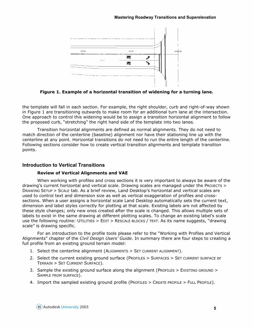
Figure 1. Example of a horizontal transition of widening for a turning lane.
the template will fall in each section. For example, the right shoulder, curb and right-of-way shown in Figure 1 are transitioning outwards to make room for an additional turn lane at the intersection. One approach to control this widening would be to assign a transition horizontal alignment to follow the proposed curb, “stretching” the right hand side of the template into two lanes.
Transition horizontal alignments are defined as normal alignments. They do not need to match direction of the centerline (baseline) alignment nor have their stationing line up with the centerline at any point. Horizontal transitions do not need to run the entire length of the centerline. Following sections consider how to create vertical transition alignments and template transition points.
Introduction to Vertical Transitions Review of Vertical Alignments and VAE
When working with profiles and cross sections it is very important to always be aware of the drawing’s current horizontal and vertical scale. Drawing scales are managed under the PROJECTS >
DRAWING SETUP > SCALE tab. As a brief review, Land Desktop’s horizontal and vertical scales are used to control text and dimension size as well as vertical exaggeration of profiles and cross-sections. When a user assigns a horizontal scale Land Desktop automatically sets the current text, dimension and label styles correctly for plotting at that scale. Existing labels are not affected by these style changes; only new ones created after the scale is changed. This allows multiple sets of labels to exist in the same drawing at different plotting scales. To change an existing label’s scale use the following routine: UTILITIES > EDIT > RESCALE BLOCKS / TEXT. As its name suggests, “drawing scale” is drawing specific.
For an introduction to the profile tools please refer to the “Working with Profiles and Vertical Alignments” chapter of the Civil Design Users’ Guide. In summary there are four steps to creating a full profile from an existing ground terrain model:
1. Select the centerline alignment (ALIGNMENTS > SET CURRENT ALIGNMENT).
2. Select the current existing ground surface (PROFILES > SURFACES > SET CURRENT SURFACE or TERRAIN > SET CURRENT SURFACE).
3. Sample the existing ground surface along the alignment (PROFILES > EXISTING GROUND >
SAMPLE FROM SURFACE).
4. Import the sampled existing ground profile (PROFILES > CREATE PROFILE > FULL PROFILE).
Mastering Roadway Transitions and Superelevation
6
Below is a summarized approach to creating a proposed vertical alignment once an existing ground profile has been imported:
1. Set the appropriate layer to hold your proposed vertical alignment current (PROFILES > FG
CENTERLINE > SET CURRENT LAYER).
2. Sketch in proposed vertical tangents along the profile (PROFILES > FG CENTERLINE TANGENTS >
CREATE TANGENTS).
3. At this point the tangents have not yet been designated as a vertical alignment. Designers are free to edit them as desired with AutoCAD Modify menu commands (trim, extend, stretch, etc.) prior to defining them as a vertical alignment.
4. Once a draft of these tangents is ready to be defined as a vertical alignment, define them through the PROFILES > FG VERTICAL ALIGNMENTS > DEFINE FG CENTERLINE command.
5. Vertical curves can be added graphically with the PROFILES > FG VERTICAL CURVES, or in the vertical alignment editor (PROFILES > EDIT VERTICAL ALIGNMENTS).
Ditches and Vertical Transitions
The previous section on horizontal alignments discussed how transition alignments could be used to stretch a template in plan. Vertical transitions allow designers to control the vertical location of the transition points with a special vertical alignment. For example, a design could define the edge of pavement horizontally with a horizontal transition alignment and vertically with a vertical transition alignment. These vertical transitions can be extremely useful in maintaining an existing edge profile (for existing curb or a sawcut line) or forcing low points for drainage. Furthermore, the same vertical transition tools can be used to control ditch inverts along the roadway in order to set maximum slopes, low point locations, etc. Keep in mind that horizontal and vertical transitions can be used independently. Horizontal transitions can be created while holding a certain slope or elevation in the template, without the aid of a vertical alignment. Likewise vertical alignments can be applied to templates without any horizontal translation.
Horizontal transitions are defined as alignments separate from the centerline. However, vertical transitions are not! They are instead included as a “ditch and transition vertical alignment” (“DT vertical”) attached to the centerline vertical alignment. This is a very important point – transition vertical alignments are part of the centerline alignment, not the transition horizontal alignment!
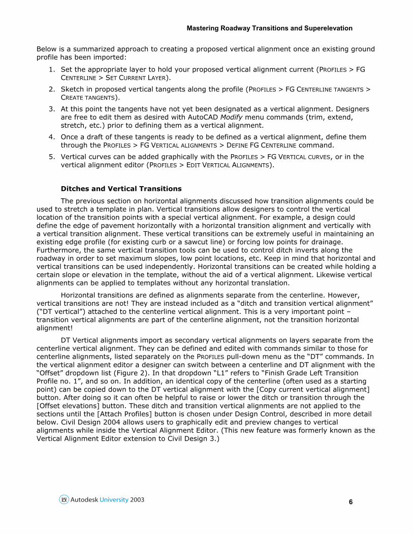
DT Vertical alignments import as secondary vertical alignments on layers separate from the centerline vertical alignment. They can be defined and edited with commands similar to those for centerline alignments, listed separately on the PROFILES pull-down menu as the “DT” commands. In the vertical alignment editor a designer can switch between a centerline and DT alignment with the “Offset” dropdown list (Figure 2). In that dropdown “L1” refers to “Finish Grade Left Transition Profile no. 1”, and so on. In addition, an identical copy of the centerline (often used as a starting point) can be copied down to the DT vertical alignment with the [Copy current vertical alignment] button. After doing so it can often be helpful to raise or lower the ditch or transition through the [Offset elevations] button. These ditch and transition vertical alignments are not applied to the sections until the [Attach Profiles] button is chosen under Design Control, described in more detail below. Civil Design 2004 allows users to graphically edit and preview changes to vertical alignments while inside the Vertical Alignment Editor. (This new feature was formerly known as the Vertical Alignment Editor extension to Civil Design 3.)
Mastering Roadway Transitions and Superelevation
7
Figure 2. The Vertical Alignment Editor.
Ditch and vertical transition alignments can be created graphically through PROFILES > DT
TANGENTS > CREATE TANGENTS and PROFILES > DT VERTICAL CURVES. When sketching DT Tangents manually, be sure to draw all linework on the expected layer for that ditch or transition before defining them as your DT alignment. The layers Civil Design expects for DT vertical alignments can be viewed and changed through PROFILES > PROFILE SETTINGS > FG LAYERS. Ditches and transition vertical alignments can be defined through PROFILES > DT VERTICAL ALIGNMENTS > DEFINE
DITCH/TRANSITION, and imported into the drawing through PROFILES > DT VERTICAL ALIGNMENTS >
IMPORT. All of the “DT” commands work similarly to their centerline vertical alignment commands (those prefixed with a FG for “Finish Ground centerline”).
Limitations of Civil Design Transitions Civil Design 2004’s transition system is powerful, flexible and generally straightforward for
most kinds of varying roadways. However, there are some important limitations that are worth noting.
As mentioned above Civil Design allows for multiple transitions on the same template; up to a total of 16 (8 on each side). Although eight custom transitions per side are often adequate for complex roadways, they need to be numbered sequentially and cannot be automatically re-numbered. This means that if you define a right curb as transition Right #1, you later decide that you will want the inside shoulder to transition independently you will have to redefine the transitions so that the shoulder is Right #1 and the curb is Right #2. One workaround for this limitation is to leave gaps in the numbering incase a new transition needs to be inserted between two others. Therefore, if you are using four transitions on a side you may consider numbering them 2, 4, 6 and 8.
Transitions can be assigned to templates that have subassemblies. Unfortunately transition points cannot be assigned inside the subassemblies, however.
Template Design for Transitions Generating Existing Cross-Sections
For an introduction to the existing ground cross section tools please refer to the “Working with Cross Sections” chapter of the Civil Design Users’ Guide. Existing cross sections based on a terrain model are created similarly to profiles. Once existing ground sections have been sampled a designer can then apply templates to represent the proposed roadway in cross-section.
Mastering Roadway Transitions and Superelevation
8
Here is a brief summary of the steps required to generate roadway sections from a terrain model:
1. Select the centerline alignment (ALIGNMENTS > SET CURRENT ALIGNMENT).
2. Select the current existing ground surface (CROSS SECTIONS > SURFACES > SET CURRENT SURFACE
or TERRAIN > SET CURRENT SURFACE).
3. Sample (calculate) cross-sections from the terrain model (CROSS SECTIONS > EXISTING GROUND
> SAMPLE FROM SURFACE).
4. Verify the sampling through the section viewer (CROSS SECTIONS > VIEW/EDIT SECTIONS).
If the sections need to be recalculated, perhaps from a centerline shift or a realignment of crossing streets or driveways, the same steps can be followed. When doing so, after step #3 users will be prompted by the question “Overwrite existing section data [Yes/No]”. This question can be somewhat misleading. Worded differently the question is asking, “Erase all sections that were not just sampled"? For example let’s say stations 10+50, 10+66, 11+00 were sampled previously. The centerline was shifted, the alignment was redefined, the profile and vertical alignment was adjusted and sections were re-sampled. The driveway at 10+66 is now located at 10+70, which was sampled as a critical station. If the user then answered “Yes” to “Overwrite existing section data” sections 10+50 and 11+00 would be re-sampled and replaced; section 10+70 would be sampled for the first time, and 10+66 would be removed from the design. A “No” answer would have the same results except the old 10+66 would remain part of the design as sampled previously. A “Yes” result is more preferable in this example but a “No” can be very useful when re-sampling a portion of an unchanged alignment (such as for a wider swath width over only a few sections). In the latter case those sections kept from the previous sampling would be unchanged and still valid.
It can be helpful when sampling cross sections choose the “save sample list” option. When doing so an ASCII text file listing each station that was sampled is generated in the project (<Project Folder> \align\<Alignment>\ <Alignment>.smp). This file can be edited directly in order to modify the sample list prior to re-sampling.
Review of Template Basics
For an introduction to the template tools please refer to the “Working with Cross Sections” chapter of the Civil Design Users’ Guide. As a brief overview, Templates are special two-dimensional “typical sections” that are located along a vertical alignment to represent proposed cross sections. Templates are made up of one or more polylines representing separate material components of the proposed roadway. Templates generally define the proposed roadbed out to, but do not include the ditches or side slopes. Template components are referred to as “surfaces” but they do not constitute Land Desktop terrain models. However, a terrain model can be generated from proposed sections very quickly with Civil 2004’s Road Output utility.
Before working with templates users should double-check that the Template Path is set correctly for the current drawing. Roadway templates are able to be shared between multiple projects. Therefore they are often stored in dedicated template libraries outside of individual project folders (the default is C:\Program Files\Land Desktop 2004\Data\tplates). The path to the current template library folder can be set under User Preferences (PROJECTS > USER PREFERENCES) and may be overridden through the Set Template Path command (CROSS SECTIONS > SET TEMPLATE PATH). Before working with any cross section tools it is best to verify that the current template folder is correct for the task at hand.
Mastering Roadway Transitions and Superelevation
9
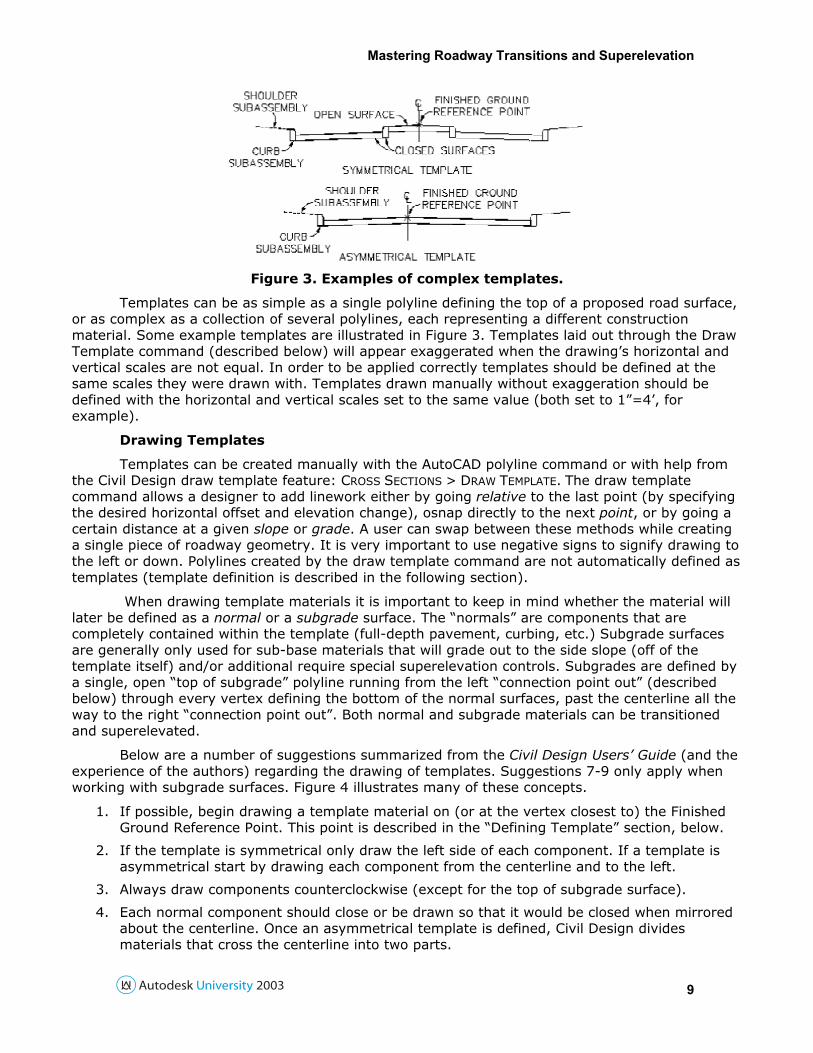
Figure 3. Examples of complex templates.
Templates can be as simple as a single polyline defining the top of a proposed road surface, or as complex as a collection of several polylines, each representing a different construction material. Some example templates are illustrated in Figure 3. Templates laid out through the Draw Template command (described below) will appear exaggerated when the drawing’s horizontal and vertical scales are not equal. In order to be applied correctly templates should be defined at the same scales they were drawn with. Templates drawn manually without exaggeration should be defined with the horizontal and vertical scales set to the same value (both set to 1”=4’, for example).
Drawing Templates
Templates can be created manually with the AutoCAD polyline command or with help from the Civil Design draw template feature: CROSS SECTIONS > DRAW TEMPLATE. The draw template command allows a designer to add linework either by going relative to the last point (by specifying the desired horizontal offset and elevation change), osnap directly to the next point, or by going a certain distance at a given slope or grade. A user can swap between these methods while creating a single piece of roadway geometry. It is very important to use negative signs to signify drawing to the left or down. Polylines created by the draw template command are not automatically defined as templates (template definition is described in the following section).
When drawing template materials it is important to keep in mind whether the material will later be defined as a normal or a subgrade surface. The “normals” are components that are completely contained within the template (full-depth pavement, curbing, etc.) Subgrade surfaces are generally only used for sub-base materials that will grade out to the side slope (off of the template itself) and/or additional require special superelevation controls. Subgrades are defined by a single, open “top of subgrade” polyline running from the left “connection point out” (described below) through every vertex defining the bottom of the normal surfaces, past the centerline all the way to the right “connection point out”. Both normal and subgrade materials can be transitioned and superelevated.
Below are a number of suggestions summarized from the Civil Design Users’ Guide (and the experience of the authors) regarding the drawing of templates. Suggestions 7-9 only apply when working with subgrade surfaces. Figure 4 illustrates many of these concepts.
1. If possible, begin drawing a template material on (or at the vertex closest to) the Finished Ground Reference Point. This point is described in the “Defining Template” section, below.
2. If the template is symmetrical only draw the left side of each component. If a template is asymmetrical start by drawing each component from the centerline and to the left.
3. Always draw components counterclockwise (except for the top of subgrade surface).
4. Each normal component should close or be drawn so that it would be closed when mirrored about the centerline. Once an asymmetrical template is defined, Civil Design divides materials that cross the centerline into two parts.
Mastering Roadway Transitions and Superelevation
10
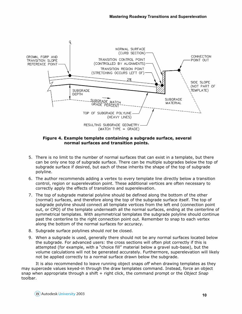
Figure 4. Example template containing a subgrade surface, several normal surfaces and transition points.
5. There is no limit to the number of normal surfaces that can exist in a template, but there can be only one top of subgrade surface. There can be multiple subgrades below the top of subgrade surface if desired, but each of these inherits the shape of the top of subgrade polyline.
6. The author recommends adding a vertex to every template line directly below a transition control, region or superelevation point. These additional vertices are often necessary to correctly apply the effects of transitions and superelevation.
7. The top of subgrade material polyline should be defined along the bottom of the other (normal) surfaces, and therefore along the top of the subgrade surface itself. The top of subgrade polyline should connect all template vertices from the left end (connection point out, or CPO) of the template underneath all the normal surfaces, ending at the centerline of symmetrical templates. With asymmetrical templates the subgrade polyline should continue past the centerline to the right connection point out. Remember to snap to each vertex along the bottom of the normal surfaces for accuracy.
8. Subgrade surface polylines should not be closed.
9. When a subgrade is used, generally there should not be any normal surfaces located below the subgrade. For advanced users: the cross sections will often plot correctly if this is attempted (for example, with a “choice fill” material below a gravel sub-base), but the volume calculations will not be generated accurately. Furthermore, superelevation will likely not be applied correctly to a normal surface drawn below the subgrade.
It is also recommended to leave running object snaps off when drawing templates as they may supercede values keyed-in through the draw templates command. Instead, force an object snap when appropriate through a shift + right click, the command prompt or the Object Snap toolbar.
Mastering Roadway Transitions and Superelevation
11
Defining Templates
Once a draft of the template geometry is complete templates can be defined with the CROSS
SECTIONS > TEMPLATES > DEFINE TEMPLATE command. During template definition the user is prompted to select all the polylines that will make up the template as well as provide the additional information outlined below. Although running osnaps may cause problems when drawing templates they can be very helpful when defining them. Generally it may be best to activate the “Endpoint” osnap prior to beginning the define command. When a point is requested it is recommended to osnap directly to the correct point on the template geometry (again see Figure 4).
• Finish Ground Reference Point (FGRP). The FGRP is the point where the template attaches to the vertical alignment. This is often the crown of an undivided roadway.
• Material Type and Name. Each material polyline needs to be identified as a normal surface or the top of subgrade surface (there may only be one per template) and given a description. The material names assigned in the “Surface Material Name” window are used only for volume calculation labels and do not affect the geometry of the proposed road. The material tables may be customized at will.
• Connection Point Out (CPO), Left and Right. The CPO is the point where the template ends and the side slopes and ditches begin. Side slope and ditch settings are managed under Civil’s Design Control dialog. CPOs do not need to be identified if a subgrade surface is used since the ends of the subgrade are the CPOs by definition.
• Datum Points. When prompted, define the datum by tracing a polyline from the left CPO along the bottom of all the material polylines to the centerline (if symmetrical) or to the right CPO (if asymmetrical). The datum is necessary to assign the boundary between the construction materials and the limit of site cut and fill. If a subgrade surface is used these points are not prompted for since the subgrade also serves as a datum. When a datum must be defined manually the user is prompted to enter a datum number. Multiple datums allow for volume calculations between different layers. If only one datum is desired assign it as #1 for simplicity.
• Subassemblies. Subassemblies are mini-templates that can be used to attach standard edge treatments to a proposed design. They can be very efficient with roadways that have a few standard curb, sidewalk and shoulder treatments. Remember that transition and superelevation points cannot be located within subassemblies.
The following are also requested when defining a template with a subgrade surface (Figure 4):
• Subgrade Depth. This is the depth of the subgrade surface measured at the centerline. Remember that a subgrade surface is defined by a single polyline along the top of the subgrade which by itself does not identify the layer’s depth.
• Subgrade Match Grade Percent. This is the slope of the bottom of the subgrade material away from the centerline, entered as whole number percent. Remember to use negative values to slope down. For example, a downwards slope of 2% would be entered as -2.
• Subgrade Match Type. This setting allows the designer to choose whether the subgrade will grade out into the ditch or side slope (grade option) or will terminate vertically at some point (vertical option).
• Subgrade vertical match offset modifier. This is the offset at which the bottom of the subgrade material will go vertical if a vertical match type is chosen. It is measured inside of the CPO in drawing units. For example, if it was desired that a gravel sub base terminate 2’ inside of the end of the template the offset modifier should be assigned a value of +2.
• Subgrade break match grade percent and Subgrade Break Point Offset Modifier. These are described in the “Designing Templates for Superelevation” section.
Mastering Roadway Transitions and Superelevation
12
Once the uppermost subgrade is fully defined you may also include additional subgrades directly beneath the topmost layer. These lower subgrades automatically assume the same shape as the subgrade layer above, but each may be given a unique depth. The bottom geometry of a subgrade surface is automatically used for the top of a subgrade below it.
Editing Templates
The edit template command (CROSS SECTIONS > TEMPLATES > EDIT TEMPLATE) allows designers to alter the geometry and material definitions of their templates. Editing templates can be a complicated process and the section on “Working with Cross Sections” of the Civil Design Users’ Guide is recommended reading. In addition to making these changes the command also allows users to add a top surface, transition and superelevation points. The top surface is an extremely helpful tool for creating terrain models from cross sections as they define the very top, exposed portion of the template. Users define top surfaces point by point across the template similarly to defining datums. Users not familiar with top surfaces are recommended to look through the Civil Design Users’ Guide for more information on them.
Transition points identify vertices to be translated along horizontal and vertical transitions. Template transition points are added through the Surface Control (SR) menu of the edit templates command. After choosing the side and transition number (1-8), two or three points are required to properly define each transition.
• Control point. This is the point referenced by the transition alignments. For a curb transition, for example, this point would often be located at the bottom of curb (the gutterline).
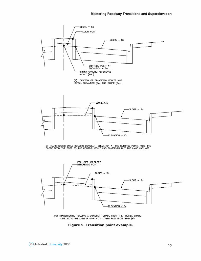
• Region point. Every transition requires a region point, located at or inside of the control point. Region points are useful to define a section of the template to be held constant through the transition. When used, stretching always ends at the region point, allowing the template geometry between the region and control points to remain constant. One example would be to locate the region point at the back of a median curb and the control point at the face of the curb. This example is illustrated in Figure 5a. This arrangement allows the back of the curb to move along with the gutter, stretching the grass strip instead of widening the curb. In this case the curb and everything to the right of it would “go along for the ride” until another transition was identified further to the right. If there is no portion of the template that needs to be held constant through the transition (often the case) the region point may be located directly on the control point.
• Vertical control (reference point): Horizontal transitions that do not have vertical transitions assigned to them are controlled vertically either by holding a cross slope grade or reference elevation constant. When desired, constant slopes are assigned by identifying a “Reference” point. When the transition occurs the slope between the region and reference points will be held constant (Figure 5C). This is very often used to hold constant lane slopes through transitions. The other alternative is to maintain a constant elevation across the transition. This option holds the elevation of the control point constant, resulting in flattening of cross grades when widening (Figure 5B). The flattening approach is typically not applied to lanes, but rather medians or other features where cross slope is less critical to the design. If a vertical transition alignment is applied this “grade” or “elevation” control is ignored.
Mastering Roadway Transitions and Superelevation
13
Figure 5. Transition point example.
Mastering Roadway Transitions and Superelevation
14
Note that when locating transition points the program asks for the region point before the control point. In addition each transition point needs to be defined as dynamic or pinned, constrained or free. Dynamic Transitions are allowed to cross the centerline, such as with a meandering median strip. The alternative (Pinned) does not allow this to happen. The Pinned option requires Land to perform fewer calculations and is generally a better option if a designer is certain a transition will not cross the centerline (like the outside edge of pavement). Constrained Transitions are not allowed to transition toward the centerline (inwards), only away. This can be a backup measure to hold an absolute minimum lane width. The alternative, Free Transitions are not restrained in any way. Designers should generally use free transitions unless they are certain they need to constrain them. Also, according to the Civil Design Users’ Guide if multiple transitions cross the centerline only the first should be defined as dynamic.
Design Control for Transitions All of the cross section components (templates, side slopes, transitions, superelevation,
etc.) come together through the design control dialog. This portion of the course notes will focus on transitioning design control features. For a more thorough description of all the design control options please refer to the chapter on “Working with Cross Sections” of the Civil Design Users’ Guide. The design control dialog is accessed under: CROSS SECTIONS > DESIGN CONTROL > EDIT DESIGN
CONTROL.
Attaching Transitions
After the transition alignments have been assigned in design control, select a template with transition points through the “templates” sub-window. Desired values for other design control features such as slopes and ditches should then be chosen. Following these, horizontal transitions are applied through the [Attach Alignments] button. In the attach alignments window the user is asked to specify the transition to be applied through a button choice. For example, to add a curb transition on the right hand side of a template through transition point #2, the designer would choose the right hand side [2] button and then select the right curb alignment. Right-of-way transitions control the location of the right of way line drawn in the cross sections. They can also be “held” by side slopes through the settings in the [Slopes] sub-window. The ditch transition can be used to define the horizontal location of the inside bottom of ditch.
The [Attach Profiles] button allows users to apply vertical transitions. As in the attach alignments window, here users can choose which vertical alignment to apply through a button choice. Afterward Civil Design does not prompt you to choose an alignment because the vertical information is already attached to the centerline profile. (Only the button pick is required to invoke the vertical transition.) Note also that in the attach profiles window there is an additional vertical transition for the apex of a template subgrade surface. The subgrade apex does not have a dedicated profile, however. To be used this apex profile must be defined in place of one of the 16 custom vertical transitions. Upon exiting the attach alignments and attach profiles sub-windows, transitions are calculated and applied to the sections.
Civil Design calculates horizontal transitions by determining and storing the offset between the transition and centerline alignments at each section. Likewise when vertical transitions are used the vertical offsets from the centerline profile are also calculated and stored. These stored values can be viewed and manipulated directly under the View/Edit Sections command, discussed below. This calculation occurs only at the time the alignments and profiles are attached. Transition controls are not automatically updated after changes are made to the horizontal or vertical transitions. Therefore every time a transition is redefined it must be “re-attached” through design control.
Mastering Roadway Transitions and Superelevation
15
Previewing and Adjusting Transitions by Section
The CROSS SECTIONS > VIEW/EDIT SECTIONS command allows designers to preview and edit the effect of their design control settings, including the effects of transitions and superelevation. View/edit sections allows users to manipulate design control settings on a station-by-station basis through the Edit (“E”) sub-menu. The edit options include a modified version of the design control window itself (“C”) where the user can swap templates as well as adjust ditch, slope and bench settings for the current section. Inside this modified design control window the [Template Control] button allows users to view and manipulate the calculated transition offsets through the [Edit Transitions] button. The horizontal and vertical offsets can also be adjusted graphically through View/Edit Section controls found in the Transitions sub-menu (“T”) of the Edit menu (“E”).
Viewing, Editing and Removing Transitions The path of transition points can be drawn in plan and profile automatically through the CROSS SECTIONS > DITCH/TRANSITIONS commands. These are simple, tremendously powerful features that are too often overlooked. The path of transition points can be drawn in plan through the command CROSS SECTIONS > DITCH/TRANSITIONS > IMPORT PLAN LINES. This feature can be especially useful to locate transition point paths of ditches or transitions that have been edited manually through view/edit sections. Just as helpful, those points can be drawn in the centerline profile through CROSS SECTIONS > DITCH/TRANSITIONS > IMPORT PROFILE. This means that transition points can be located along important template points (such as gutter lines) and their profiles can be automatically generated. All changes made through design control and view/edit sections will be reflected in these profiles and plan layouts. In fact, template points can be drawn in plan and profile even if a transition isn’t applied through design control; as long as there are transition points in the template these features can track them.
Transition paths in plan view are drawn on the current layer. Transition profiles are drawn on specific layers based on the settings in PROFILES > PROFILE SETTINGS > FG LAYERS. Plan lines and profiles generated by these commands will be segmented lines drawn between sampled cross-section stations (they will not contain horizontal or vertical curves). One way to make these lines appear smoother is to sample additional cross-sections along curves and spirals before importing.
As an advanced technique these imported plan lines and profiles can be edited and then defined as transition alignments (ALIGNMENTS > DEFINE commands and PROFILES > DT VERTICAL
ALIGNMENTS > DEFINE DITCH/TRANSITION). For example, the resulting layout of a ditch defined through foreslope and depth in design control can be imported into plan and profile. This linework can be adjusted directly, possibly to avoid a structure in plan and/or force a low point in profile. Horizontal and vertical curves can also be added to clean up the horizontal and vertical linework. After adjustment the plan linework can then be defined as a horizontal alignment and the profile as a ditch transition. In design control the ditch transitions can be assigned to follow these alignments. Once assigned, these transitions will override the original depth and foreslope settings. A thorough breakdown of these steps is provided in the following section. A drawback to working with the imported lines directly is that, again, they are segmented and do not contain any curve information. In some cases a better approach may be to trace over the imported lines with new, less complex linework.
Again, it is very important to remember that re-defined alignments are not automatically taken into account by transitions. When necessary, adjustments to transition horizontal or vertical alignments need to be re-applied through design control. Transitions can be removed from the design through design control’s [Templates] window, [Edit Transitions] sub-window. If the checkboxes adjacent to the transition fields are de-selected the transitions will be ignored over the current station range.
Mastering Roadway Transitions and Superelevation
16
Bringing It All Together: Example Approach Let’s consider at an example in detail. Take for instance a subdivision road design that has a
horizontal transition applied to control widening for an additional turn lane at the crossing street, similar to the horizontal configuration in Figure 1. The proposed cross section includes a constant-width curb and gutter section as illustrated in Figure 4.
1. The centerline alignment is defined. A profile is sampled, imported, and a proposed centerline vertical alignment is created.
2. Existing ground cross-sections are sampled. After a quick check to verify them in View/Edit Sections we are ready to create a template.
3. The template is drawn with a 2% slope from the crown to the edge of the curb section, as shown in Figure 4. The template is defined and named.
4. Our design includes the path of the gutterline (face of curbing) but not the inside edge of the curb section. Therefore it is decided that the gutterline would be the most convenient transition control point. The gutterline linework in plan is defined as a horizontal alignment. When working with multiple transitions it may be helpful to adopt naming conventions such as “P-ETW-R” for ‘proposed edge of traveled way - right’. After this the roadway centerline is immediately made current again to avoid accidentally using the gutter alignment as the centerline.
5. Since the curb section is constant width the lane widening should occur by translating the left edge of curb rather than the gutter (which is our control point). To make this happen the inside edge of the curb section will be defined as the region point.
6. The template is then edited in order to add the gutter transition. We choose to add the gutterline as right side transition #2 (leaving #1 available just incase it is needed later on). The region point is chosen at the inside edge of the curb section, the control point is assigned at the gutter. Since the transition does not cross the centerline it is defined as pinned. We don’t have any reason to prevent the template from contracting so we also define it as free. The transition will be controlled vertically by slope in order to hold the 2% crown. This is accomplished by choosing the crown as the reference point.
7. In design control we choose our transition template as well as appropriate slope, ditch and bench settings.
8. Lastly, before leaving design control we attach our horizontal transition through the [Attach Alignments] button. On the right hand side of the following window the [Two] button is chosen to line up with transition point #2 on the template. When prompted for the alignment to use we click on the linework for “P-ETW-R”, or press enter and choose it from the list of all project alignments.
At this point we have now applied our horizontal transition and the template can be seen to widen in View/Edit Sections. Taking the design to the next step we can use vertical transition tools to control the flattening of the lane’s cross grade as we approach an intersection.
9. To view where the transitioning gutter-line falls in profile we can use the CROSS SECTIONS >
DITCH/TRANSITION > IMPORT PROFILE command. When prompted we ask for the right hand side transition profile #2.
10. Initially the design shows a 2% crown all the way into the intersection. One approach to flatten the cross-slope and promote drainage away from the intersection would be to raise the gutterline profile as we approach the intersection, forcing a low point back along the subdivision road.
Mastering Roadway Transitions and Superelevation
17
11. The gutter profile we imported can be adjusted and then defined as a transition vertical alignment. The gutter profile can be edited manually or through the help of commands in the PROFILES > DT TANGENTS menu. Once edited, the linework can be defined as a transition vertical alignment through CROSS SECTIONS > DITCH/TRANSITIONS > DEFINE PROFILE ALIGNMENT.
12. A vertical transition alignment can be created from scratch in the vertical alignment editor (PROFILES > EDIT VERTICAL ALIGNMENTS) by choosing “R2” instead of “Centerline” in the profile drop-down list. This profile can be imported into the drawing for inspection through CROSS SECTIONS > DT VERTICAL ALIGNMENTS > IMPORT.
13. Once we are satisfied with a draft of our gutter profile we can then apply it to our sections through Design Control with the [Attach Profiles] button, choosing the right side transition #2. The desired vertical control should now be visible in View/Edit sections.
As mentioned previously these same controls allow designers to locate right-of-way lines and ditches in their sections as well. When applying both horizontal and vertical control to ditches step #10 above should be broken down into the following sub-steps. For more information on this topic please see Autodesk’s technical document TS73301 “Using ditches with horizontal and vertical control”. This order is important for the ditch to be defined correctly.
a. Once the ditch horizontal and vertical alignments have been defined, enter the design control window and view the current ditch settings. If necessary change the controls to Centerline Offset and Base Elevations, which can be set to zeros at this point.
b. Next choose [Attach Profiles] to choose the ditch vertical transition. In this window choose centerline offset as the other parameter and enter the desired base width.
c. Lastly, return to the main window and [Attach Alignments] for the ditch horizontal alignment.
Complex Transitions The above example highlighted a template that followed a single transition. As mentioned previously each template can have several transitions applied to it. For example a highway design could have transitions for the inside median, shoulder lines, lane line, outside curb, front of walk, back of walk and right-of-way all on the same template. When using multiple transitions the region point becomes very important; it should always be located on the transition control point unless there is a constant-width section on the template to the inside (such as a constant-width shoulder, grass strip or top of curbing).
Transitions can save a great deal of drafting effort when dealing with divided roadways. If the innermost left and right transitions are assigned to the median edges and both are “dynamic” these transitions can cross the centerline. This can be very helpful when the median jumps over the centerline at opposing turn lanes. Whenever two horizontal transitions overlap the geometry between the transition points in the template is ignored. Therefore, in a divided roadway template if the median transition alignments were defined to overlap inside of an intersection the median would disappear! A thorough explanation of this feature is provided in Autodesk’s technical document TS65363.
Lastly, Civil Design 3 and 2004 are able to generate existing ground profiles for use as vertical transitions very easily thanks to the superimpose profiles utility. On reconstruction projects this feature allows a designer to locate a transition along the bottom of an existing curb, a sawcut line or similar existing feature, and then project its profile against the centerline alignment. These projected profiles are ready-made vertical transition alignments. Other sessions at Autodesk University go into more detail on this topic.
Mastering Roadway Transitions and Superelevation
18
The following is a summary of steps to generate an offset profile based on existing ground, and use that profile as a transition vertical alignment for a partial reconstruction template.
1. Create a terrain model representing existing conditions. Create a profile and sample cross sections along the centerline.
2. Draw and define a template that represents the intended work. At least one transition point should be assigned along the outside edge that will follow the existing feature (bottom of curb, sawcut line, etc.)
3. Define a transition alignment that follows the existing feature (sawcut line, curbing, etc.) in plan view, adjacent to the centerline.
4. Sample a profile along the transition alignment. It is not necessary to create or import a profile for the transition as we can superimpose the sampled data directly to the centerline.
5. Set the centerline current again. Launch the superimpose profiles command (PROFILES >
UTILITIES > SUPERIMPOSE PROFILES). Choose the transition alignment as the “horizontal alignment” to project, choose the appropriate transition layer to draw on and click [Draw]. For example, if the superimposed profile is going to control the elevation of the template through right transition point #2 the default layer should be “PFGR2”. (These layer names can be viewed and changed under PROFILES > PROFILE SETTINGS > FG LAYERS.)
6. If the projected profile is too complex you may wish to simplify it somewhat. When happy with the linework representing the existing profile define it as a vertical transition alignment (PROFILES > DT VERTICAL ALIGNMENTS > DEFINE DITCH/TRANSITION).
7. Attach the transition alignment and profile in design control. In View/Edit sections the partial reconstruction template should appear connected to the existing feature.
For more information on transition topics please consider the following Autodesk technical documents:
TS66393 “Overview of working with transitions”
TS66187 “Troubleshooting transitions”
TS73290 “Match template connection point out to existing ground daylight”
TS74514 “Individually edited stations are not overwritten when parameters are applied in design control”
Mastering Roadway Transitions and Superelevation
19
Part 2: Superelevation
Getting Started with Superelevation Designing superelevated roadways can be an involved process. Users are strongly
recommended to brush up on the engineering principles of superelevation and the Civil Design Users’ Guide before attempting to use this tool for the first time. Civil Design has a powerful and relatively straightforward approach to laying out superelevated curves. It doesn’t actually design the curves, however, and some prep work is normally required. Before doing anything in the software it is important to first consider the following design issues. Each of these will be considered in following sections.
A. What is the desired full (maximum) superelevation rate (emax) based on design speed, curve radius and other layout constraints?
B. What is the required length of runoff and runout (described below) based on allowable rates of superelevation change? The rate of superelevation change is the change in cross-section grade along the alignment, often evaluated through edge profiles, time/speed rules and so on. Ideally these should be chosen so that the rate of superelevation change is the same in the runout and runoff.
C. How much of the superelevation will be applied on the adjacent tangents? Civil Design can develop (and remove) superelevation fully on the tangents or at a fixed ratio such as 2/3 before (and after) the curve.
D. Will the subgrade surface (if one is present) be rotated parallel to the roadway or break and grade down on the high side?
E. Will a rollover region be present to help reduce the grade difference between the superelevated lane and the shoulder? These regions, also known as “shoulder breaks” or “high side breaks” are controlled through a maximum grade separation between the lane and the rollover region.
F. Will the crown removal point be assigned at the same distance as the runout along the runoff? This is handled through the “crown removal by runout distance” option under the superelevation parameters dialog.
Superelevation controls are located in four separate locations in Civil Design. These locations are listed below for reference when troubleshooting. Each topic is considered in detail in the following sections.
1. Templates that include a subgrade surface must have a subgrade break point defined. Break points are necessary in case the fixed break rotation method is chosen later through superelevation parameters.
2. Templates need to be edited in order to add superelevation points. These points control where the superelevation and rollover regions exist on a template.
3. Design parameters, such as emax and runoff length, need to be assigned through the superelevation parameters dialog.
4. Once processed, superelevation parameters can be overridden by controls in the [Templates] window of the Design Control dialog and through View/Edit sections. If these are not intentionally adjusted, however, the superelevation will follow the settings applied through the superelevation parameters dialog.
Mastering Roadway Transitions and Superelevation
20
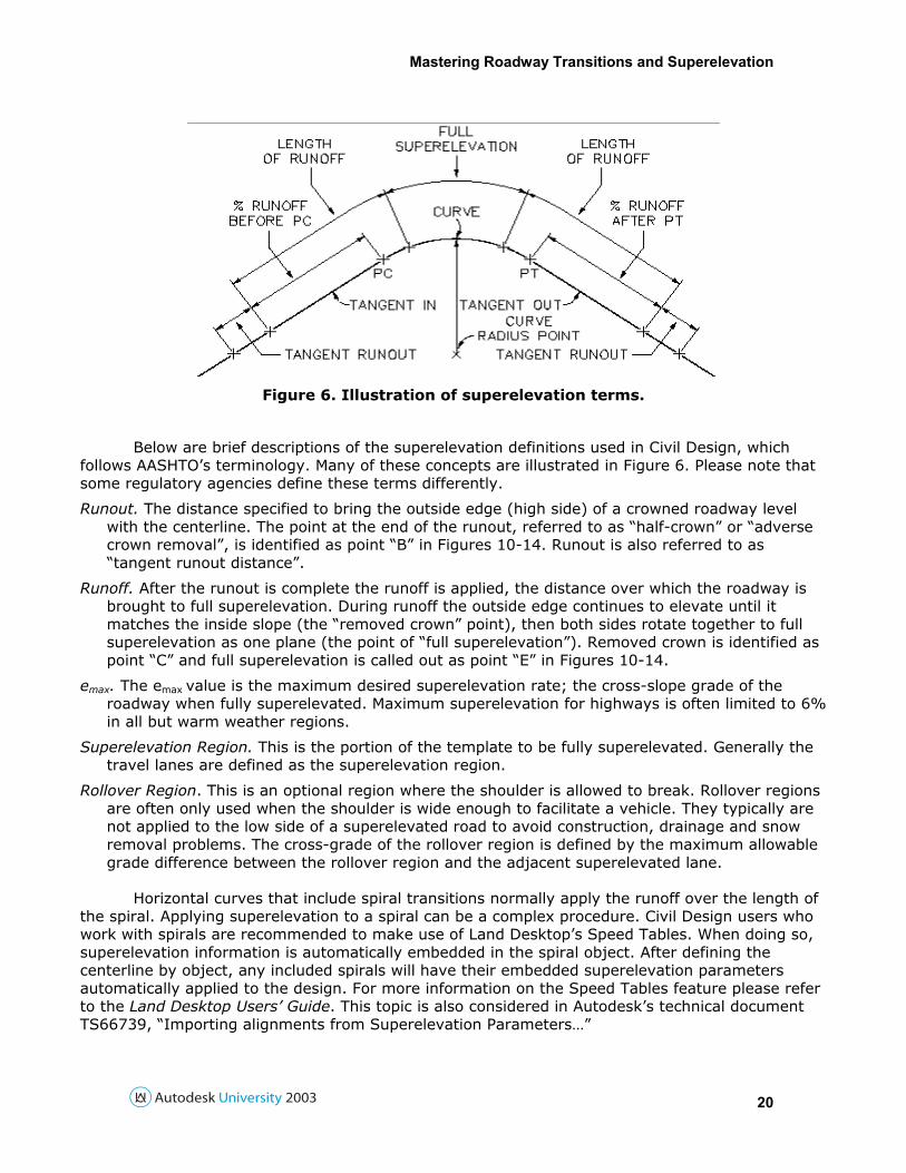
Figure 6. Illustration of superelevation terms.
Below are brief descriptions of the superelevation definitions used in Civil Design, which follows AASHTO’s terminology. Many of these concepts are illustrated in Figure 6. Please note that some regulatory agencies define these terms differently.
Runout. The distance specified to bring the outside edge (high side) of a crowned roadway level with the centerline. The point at the end of the runout, referred to as “half-crown” or “adverse crown removal”, is identified as point “B” in Figures 10-14. Runout is also referred to as “tangent runout distance”.
Runoff. After the runout is complete the runoff is applied, the distance over which the roadway is brought to full superelevation. During runoff the outside edge continues to elevate until it matches the inside slope (the “removed crown” point), then both sides rotate together to full superelevation as one plane (the point of “full superelevation”). Removed crown is identified as point “C” and full superelevation is called out as point “E” in Figures 10-14.
emax. The emax value is the maximum desired superelevation rate; the cross-slope grade of the roadway when fully superelevated. Maximum superelevation for highways is often limited to 6% in all but warm weather regions.
Superelevation Region. This is the portion of the template to be fully superelevated. Generally the travel lanes are defined as the superelevation region.
Rollover Region. This is an optional region where the shoulder is allowed to break. Rollover regions are often only used when the shoulder is wide enough to facilitate a vehicle. They typically are not applied to the low side of a superelevated road to avoid construction, drainage and snow removal problems. The cross-grade of the rollover region is defined by the maximum allowable grade difference between the rollover region and the adjacent superelevated lane.
Horizontal curves that include spiral transitions normally apply the runoff over the length of the spiral. Applying superelevation to a spiral can be a complex procedure. Civil Design users who work with spirals are recommended to make use of Land Desktop’s Speed Tables. When doing so, superelevation information is automatically embedded in the spiral object. After defining the centerline by object, any included spirals will have their embedded superelevation parameters automatically applied to the design. For more information on the Speed Tables feature please refer to the Land Desktop Users’ Guide. This topic is also considered in Autodesk’s technical document TS66739, “Importing alignments from Superelevation Parameters…”
Mastering Roadway Transitions and Superelevation
21
Limitations of Civil Design Superelevation Civil Design’s superelevation system is best suited for roads where each side rotates as a
single plane and there is only one rollover region per side. Multi-lane highways that have varying rates of superelevation change on each side or that require multiple rollover slopes may instead need to be handled in Civil Design as transitions. The later section on “Importing and Editing Edge Profiles” describes an approach that can transfer superelevation profiles into transitions. Superelevation points cannot be assigned within a sub-assembly shoulder. Another limitation is that rollover regions in a template that wind up on the low side of a turn cannot be automatically “turned off”. A workaround for this issue considered in the following sections.
Civil Design considers the point at which the high-side lane begins to superelevate as the beginning of the superelevation. This may be a problem if a shoulder rollover region starts with a different slope than the lane under normal crown conditions. Civil Design is not able to automatically superelevate the shoulder first if the shoulder and lane must have the same slope prior to the lane being superelevated. In this situation a manual approach can be used as a workaround. Also, if local guidance does not define the rollover region as a constant grade difference from the lane, rollover values may need to be manually calculated and applied at each section. For example, the rollover region may be required to match the lane slope up to 2%. This can be achieved by assigning a rollover at 0% everywhere except where the lane is at 2% or higher, where the rollover will need be set manually station-by-station through the view/edit sections command. These workarounds are discussed in detail in Autodesk’s technical document TS68429.
Designing Templates for Superelevation Subgrade Surface Parameters
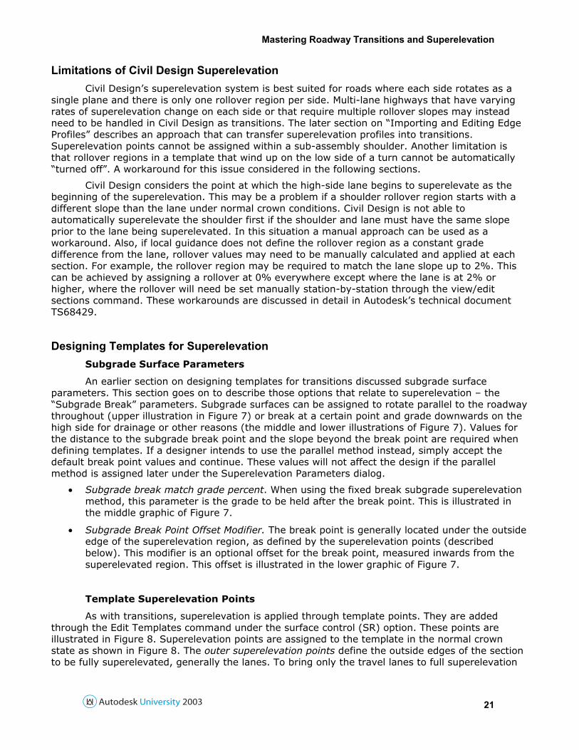
An earlier section on designing templates for transitions discussed subgrade surface parameters. This section goes on to describe those options that relate to superelevation – the “Subgrade Break” parameters. Subgrade surfaces can be assigned to rotate parallel to the roadway throughout (upper illustration in Figure 7) or break at a certain point and grade downwards on the high side for drainage or other reasons (the middle and lower illustrations of Figure 7). Values for the distance to the subgrade break point and the slope beyond the break point are required when defining templates. If a designer intends to use the parallel method instead, simply accept the default break point values and continue. These values will not affect the design if the parallel method is assigned later under the Superelevation Parameters dialog.
• Subgrade break match grade percent. When using the fixed break subgrade superelevation method, this parameter is the grade to be held after the break point. This is illustrated in the middle graphic of Figure 7.
• Subgrade Break Point Offset Modifier. The break point is generally located under the outside edge of the superelevation region, as defined by the superelevation points (described below). This modifier is an optional offset for the break point, measured inwards from the superelevated region. This offset is illustrated in the lower graphic of Figure 7.
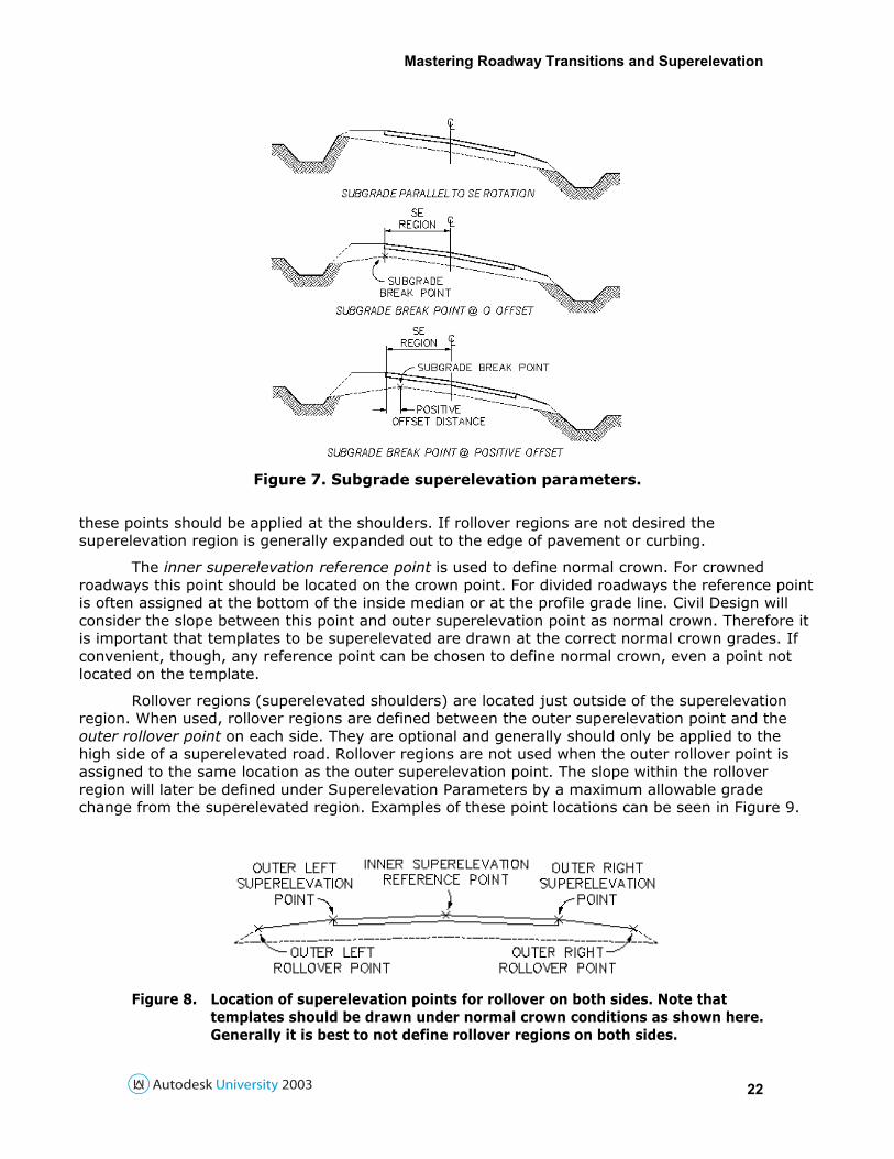
Template Superelevation Points
As with transitions, superelevation is applied through template points. They are added through the Edit Templates command under the surface control (SR) option. These points are illustrated in Figure 8. Superelevation points are assigned to the template in the normal crown state as shown in Figure 8. The outer superelevation points define the outside edges of the section to be fully superelevated, generally the lanes. To bring only the travel lanes to full superelevation
Mastering Roadway Transitions and Superelevation
22
Figure 7. Subgrade superelevation parameters.
these points should be applied at the shoulders. If rollover regions are not desired the superelevation region is generally expanded out to the edge of pavement or curbing.
The inner superelevation reference point is used to define normal crown. For crowned roadways this point should be located on the crown point. For divided roadways the reference point is often assigned at the bottom of the inside median or at the profile grade line. Civil Design will consider the slope between this point and outer superelevation point as normal crown. Therefore it is important that templates to be superelevated are drawn at the correct normal crown grades. If convenient, though, any reference point can be chosen to define normal crown, even a point not located on the template.
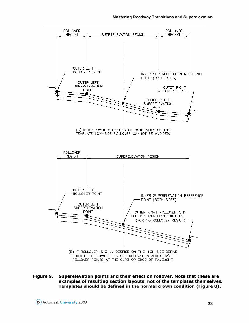
Rollover regions (superelevated shoulders) are located just outside of the superelevation region. When used, rollover regions are defined between the outer superelevation point and the outer rollover point on each side. They are optional and generally should only be applied to the high side of a superelevated road. Rollover regions are not used when the outer rollover point is assigned to the same location as the outer superelevation point. The slope within the rollover region will later be defined under Superelevation Parameters by a maximum allowable grade change from the superelevated region. Examples of these point locations can be seen in Figure 9.
Figure 8. Location of superelevation points for rollover on both sides. Note that templates should be drawn under normal crown conditions as shown here. Generally it is best to not define rollover regions on both sides.
Mastering Roadway Transitions and Superelevation
23
Figure 9. Superelevation points and their effect on rollover. Note that these are examples of resulting section layouts, not of the templates themselves. Templates should be defined in the normal crown condition (Figure 8).
Mastering Roadway Transitions and Superelevation
24
One important limitation to Civil Design’s superelevation system is that a low side rollover region cannot be automatically ignored, as shown in Figure 9a. Low side rollovers are often avoided to prevent drainage, construction and snow removal issues. Therefore a roadway having superelevated right and left turns will generally require two templates: one with a rollover region on the left and one with a rollover region on the right. These templates will need to be interchanged as the road turns left and right through design control. When editing templates Civil Design asks for these points in a very specific order, so please read the command line carefully when assigning them.
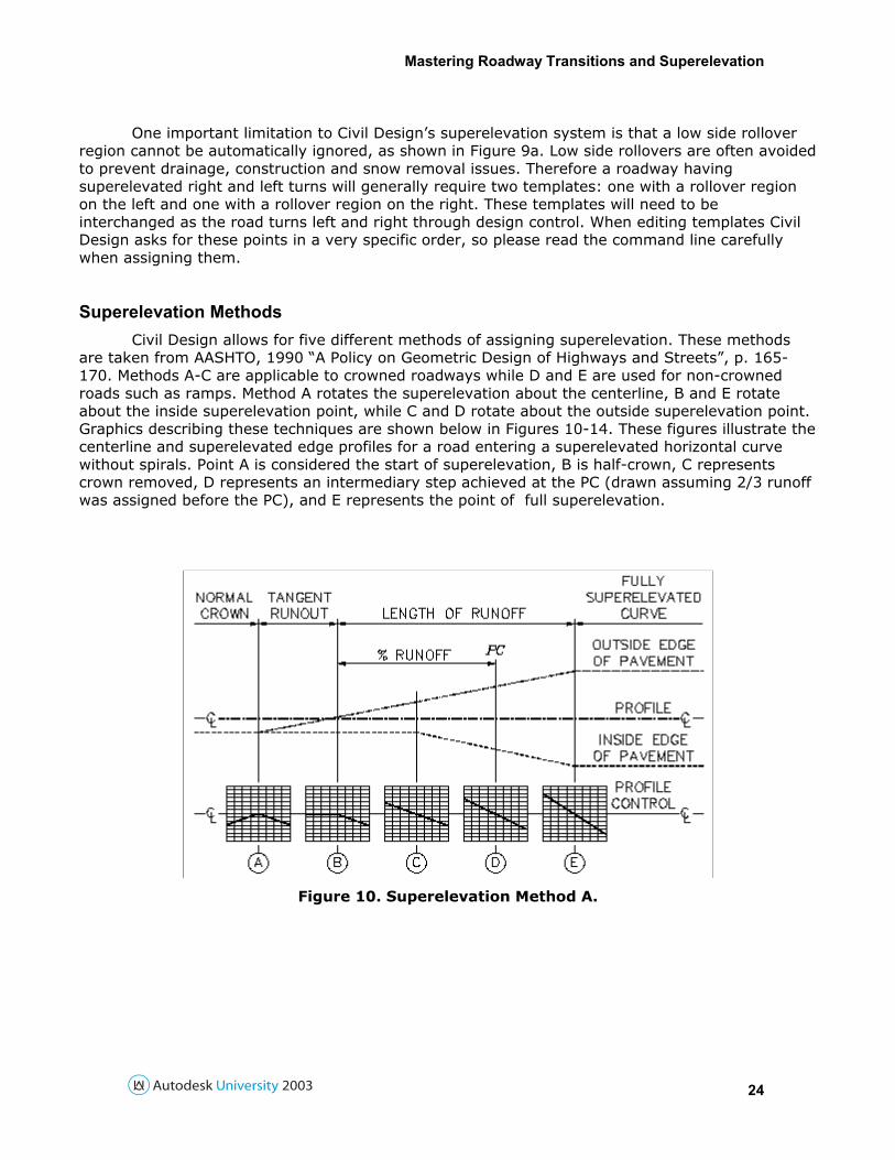
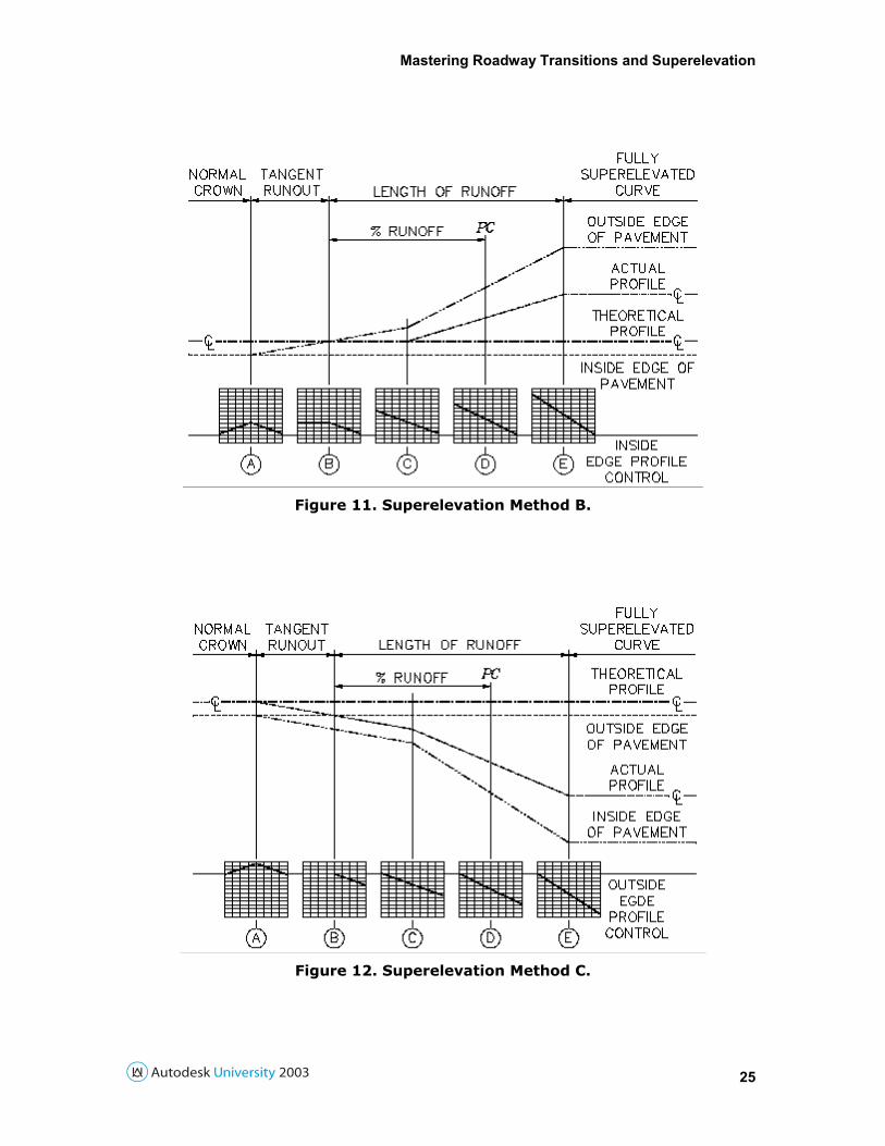
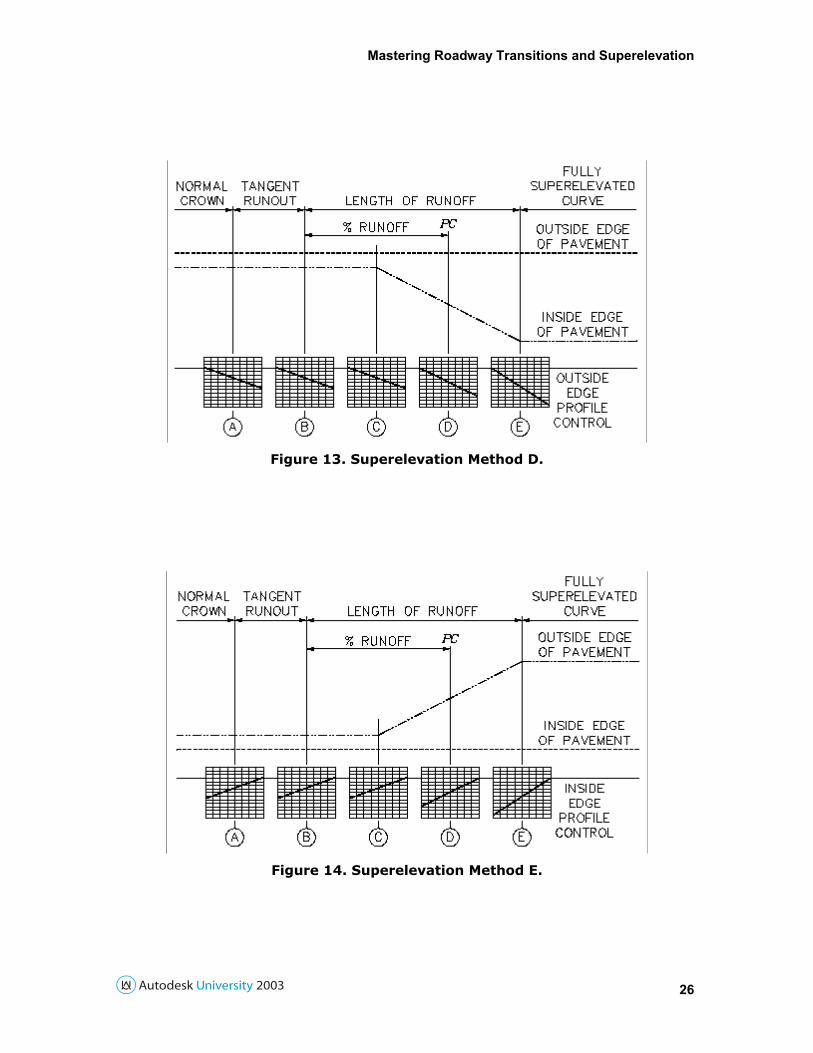
Superelevation Methods Civil Design allows for five different methods of assigning superelevation. These methods
are taken from AASHTO, 1990 “A Policy on Geometric Design of Highways and Streets”, p. 165-170. Methods A-C are applicable to crowned roadways while D and E are used for non-crowned roads such as ramps. Method A rotates the superelevation about the centerline, B and E rotate about the inside superelevation point, while C and D rotate about the outside superelevation point. Graphics describing these techniques are shown below in Figures 10-14. These figures illustrate the centerline and superelevated edge profiles for a road entering a superelevated horizontal curve without spirals. Point A is considered the start of superelevation, B is half-crown, C represents crown removed, D represents an intermediary step achieved at the PC (drawn assuming 2/3 runoff was assigned before the PC), and E represents the point of full superelevation.
Figure 10. Superelevation Method A.
Mastering Roadway Transitions and Superelevation
25
Figure 11. Superelevation Method B.
Figure 12. Superelevation Method C.
Mastering Roadway Transitions and Superelevation
26
Figure 13. Superelevation Method D.
Figure 14. Superelevation Method E.
Mastering Roadway Transitions and Superelevation
27
Superelevation Parameters The Superelevation Parameters dialog controls how and where superelevation is applied.
The window is accessible through CROSS SECTIONS > DESIGN CONTROL > SUPERELEVATION PARAMETERS. The “Superelevation Calculations” toggle is a global on/off switch for the superelevation engine. If this toggle is off none of the superelevation settings will be applied to the current centerline. This toggle should normally be left on at all times superelevation is desired. The second toggle “Crown Removal by Runout Distance” is described in a following section.
Civil Design automatically assigns each horizontal curve to have superelevation data as specified in the [Settings] sub-window. These settings include emax, runoff lengths, etc. To simultaneously change the superelevation values of multiple curves, choose the desired options in the [Settings] sub-window, close it and choose the [Import Alignments] button. To view or adjust settings for an individual curve use the [Edit Data] button, described below. The [Methods] button offers a brief review of the five superelevation methods described in Figures 10-14. The report buttons generate text reports of the assigned superelevation information. The [Save] button will save the current superelevation settings and allow the designer to continue working.
The heart of the superelevation system is contained in the [Edit Data] sub-window, where the design parameters (emax, runoff length, etc.) can be viewed and adjusted independently for each curve. Note that if the method is set to “None” (the default) there will be no superelevation over this curve. A curve not likely to be superelevated can be excluded from the list with the [Delete Curve] button if desired. This command will not delete the curve from the horizontal alignment; it only removes any superelevation information from it. Superelevation curves that have been deleted can be reinstated with the “Insert Curve” button. The insert curve feature can also be used to create a superelevated region over a horizontal tangent if desired for drainage or other reasons.
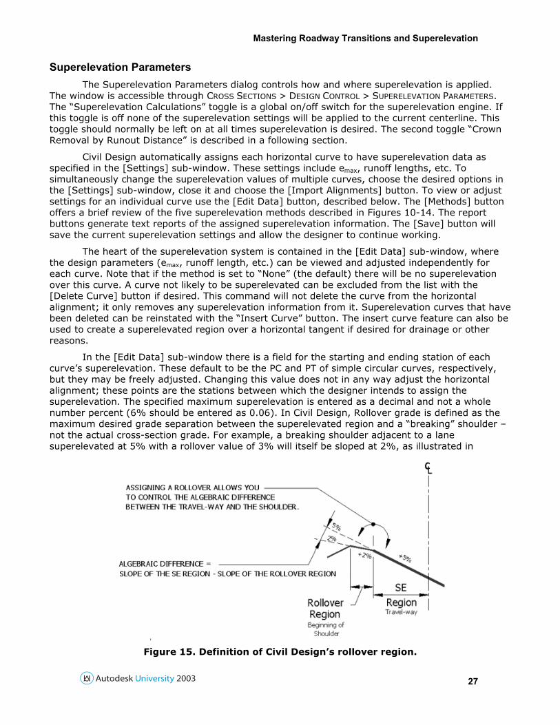
In the [Edit Data] sub-window there is a field for the starting and ending station of each curve’s superelevation. These default to be the PC and PT of simple circular curves, respectively, but they may be freely adjusted. Changing this value does not in any way adjust the horizontal alignment; these points are the stations between which the designer intends to assign the superelevation. The specified maximum superelevation is entered as a decimal and not a whole number percent (6% should be entered as 0.06). In Civil Design, Rollover grade is defined as the maximum desired grade separation between the superelevated region and a “breaking” shoulder – not the actual cross-section grade. For example, a breaking shoulder adjacent to a lane superelevated at 5% with a rollover value of 3% will itself be sloped at 2%, as illustrated in
Figure 15. Definition of Civil Design’s rollover region.
Mastering Roadway Transitions and Superelevation
28
Figure 15. When exiting the curve if that same lane is at 3.5% the shoulder will be at 0.5%. As with superelevation values rollovers should be entered in decimal percents (3% should be entered as 0.03).
Runout and Runoff lengths are entered in the appropriate fields as drawing units (feet or meters depending on the design). The %runoff is the amount of runoff desired before (and after) the starting (and ending) stations entered in the fields above. Unlike the superelevation and rollover values, however, the %runoff should be entered in whole number percents (66.67% should be entered as 66.67). Take for instance a road with a superelevated, simple horizontal curve. It has a PC located at station 15+33, a required runout length of 50’, runoff of 150’ and 2/3 of the superelevation is desired before the PC. One approach would be to leave the “starting station” at the PC, enter 66.67 for %runoff and the appropriate lengths for runout and runoff. This would result in the superelevation starting at station 13+83 (1533 - 2/3(150) - 50) and full superelevation occurring at 15+83 (1533 + 1/3(150)). However, if it was desired to have the superelevation key stations fall at even 5-foot intervals the “starting station” could be assigned to be 15+35, which would result in the superelevation starting at 13+85 and ending at 15+85. If a designer would prefer to explicitly locate the point of full superelevation they could do so by assigning the “starting station” to the desired station and choosing a value of 100 for %runoff. These settings are configured similarly for the transition out controls, which are independent of the transition in values. Since there is no crown removal in methods D and E, their runouts should always be set to zero.
The [Subgrades] sub-dialog is used to assign the transition type for a template subgrade surface (if used) and additional transition lengths for the subgrade roll. A subgrade transition of “fixed break” causes the subgrade slope to break and grade down outside of the break point defined in the template. A “parallel” setting will force the subgrade parallel to the superelevation at all times while “none” will cause the subgrade not to superelevate at all. These subgrade options are illustrated in Figure 7.
Once superelevation parameters have been saved and the dialog is closed the cross-sections are processed. Following processing Civil Design 3 and 2004 prompt the user to automatically sample the critical superelevation stations (start, half-crown, removed crown, etc.) and add them to the section list. Once the dialog is closed the superelevation should be visible in View/Edit Sections.
Crown Removal by Runout Distance
This option in the Superelevation Parameters dialog allows the designer to choose whether or not the crown removal point (point C on Figures 10-12) is reached at the runout distance along the runoff. For example, if the appropriate runout is calculated to be 60’ and the runoff 180’, if “removal by runout” is desired then crown removal will occur 60’ into the runoff, 120’ from the start of superelevation. This option does not apply to non-crowned roadways described in Figures 14 and 15. This constraint, also referred to as the “removal by runout” option, and is often specified by highway departments.
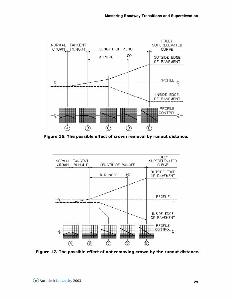
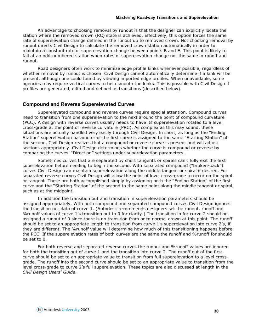
As mentioned previously it is normally best to have the same rate of superelevation change in the runout and runoff. If this is unavoidable, such as if the superelevation regions are asymmetric (having different numbers of lanes) or both sides do not begin at the same normal crown, there may be an angle point (“kink”) in the high-side edge profile of the superelevation region. Effectively, choosing this option will force the kink at the removed crown point (visible at point C in Figure 16) and not choosing it will force the kink at the half-crown point (visible at point B in Figure 17). Generally speaking, remove crown will occur at the same station whether this option is chosen or not for symmetrical roads with the same rate of superelevation change in runout and runoff.
Mastering Roadway Transitions and Superelevation
29
Figure 16. The possible effect of crown removal by runout distance.
Figure 17. The possible effect of not removing crown by the runout distance.
Mastering Roadway Transitions and Superelevation
30
An advantage to choosing removal by runout is that the designer can explicitly locate the station where the removed crown (RC) state is achieved. Effectively, this option forces the same rate of superelevation change defined in the runout up to removed crown. Not choosing removal by runout directs Civil Design to calculate the removed crown station automatically in order to maintain a constant rate of superelevation change between points B and E. This point is likely to fall at an odd-numbered station when rates of superelevation change not the same in runoff and runout.
Road designers often work to minimize edge profile kinks whenever possible, regardless of whether removal by runout is chosen. Civil Design cannot automatically determine if a kink will be present, although one could found by viewing imported edge profiles. When unavoidable, some agencies may require vertical curves to help smooth the kinks. This is possible with Civil Design if profiles are generated, edited and defined as transitions (described below).
Compound and Reverse Superelevated Curves Superelevated compound and reverse curves require special attention. Compound curves
need to transition from one superelevation to the next around the point of compound curvature (PCC). A design with reverse curves usually needs to have its superelevation rotated to a level cross-grade at the point of reverse curvature (PRC). As complex as this may sound, these situations are actually handled very easily through Civil Design. In short, as long as the “Ending Station” superelevation parameter of the first curve is assigned to the same “Starting Station” of the second, Civil Design realizes that a compound or reverse curve is present and will adjust sections appropriately. Civil Design determines whether the curve is compound or reverse by comparing the curves’ “Direction” settings under superelevation parameters.
Sometimes curves that are separated by short tangents or spirals can’t fully exit the first superelevation before needing to begin the second. With separated compound (“broken-back”) curves Civil Design can maintain superelevation along the middle tangent or spiral if desired. For separated reverse curves Civil Design will allow the point of level cross-grade to occur on the spiral or tangent. These are both accomplished simply by assigning both the “Ending Station” of the first curve and the “Starting Station” of the second to the same point along the middle tangent or spiral, such as at the midpoint.
In addition the transition out and transition in superelevation parameters should be assigned appropriately. With both compound and separated compound curves Civil Design ignores the transition out data of curve 1. (Autodesk recommends designers set the runout, runoff and %runoff values of curve 1’s transition out to 0 for clarity.) The transition in for curve 2 should be assigned a runout of 0 since there is no transition from or to normal crown at this point. The runoff should be set to an appropriate length to transition from curve 1’s superelevation into curve 2’s, if they are different. The %runoff value will determine how much of this transitioning happens before the PCC. If the superelevation rates of both curves are the same the runoff and %runoff for should be set to 0.
For both reverse and separated reverse curves the runout and %runoff values are ignored for both the transition out of curve 1 and the transition into curve 2. The runoff out of the first curve should be set to an appropriate value to transition from full superelevation to a level cross-grade. The runoff into the second curve should be set to an appropriate value to transition from the level cross-grade to curve 2’s full superelevation. These topics are also discussed at length in the Civil Design Users’ Guide.
Mastering Roadway Transitions and Superelevation
31
Editing Superelevation Parameters by Station As with transitions, superelevation parameters can be edited manually thorough the edit
menu of view/edit sections. From the edit menu choose “C” for the design control dialog. Inside this window choose [Template Control] to view and edit this station’s superelevation and rollover parameters, including the cross-slopes of the superelevation regions. Although not preferable, when necessary designers can apply manually calculated superelevation steps to a roadway on a section-by-section basis. This is one way to apply a complex superelevation that requires special attention, such as shoulders with varying rollover rates. This topic is considered in the Autodesk technical document TS68429, “Assign varying superelevation rollover values”.
Importing and Editing Edge Profiles The Part 1 section on “Viewing, Editing and Removing Transitions” discussed the CROSS
SECTIONS > DITCH/TRANSITION menu commands which allow a transition point to be tracked in plan and profile. These same commands can also be used to track outer superelevation points. In other words, the profile for the outer superelevation point on each side can be automatically drawn along the centerline profile. The outer rollover point, or any other important point on the template for that matter, can be tracked by these commands if a transition point is located there.
As an advanced technique, these imported profiles can be edited manually, defined as vertical transitions and applied to the cross sections. This is how vertical curves can be added to superelevated edge profiles to help reduce the effects of angle points. In order for this to work the template needs to have a transition point applied at each outer superelevation and rollover point. Once the superelevation has been applied through design control, import transition profiles for the transition points that correspond to superelevation points. Edit the profiles or redraw as necessary, then define each profile as a ditch/transition vertical alignment. The next step is to turn off superelevation calculations in design control since that information is now defined through transitions. Lastly, in design control assign these vertical transitions through the [Attach Profiles] button. This topic is also discussed in the Autodesk technical document TS27975, “Creating a non-standard superelevation using vertical transition profiles”.
Superelevation Reports A list of superelevation settings by station can be generated from the DESIGN CONTROL >
SUPERELEVATION PARAMETERS > [Output] button. The best way to generate a report of superelevated edge profile elevations in Civil Design 2004 is through the vertical alignment editor. To do so, add transition points at the outer superelevation and rollover points and create transition profiles from them. Define those profiles as ditch/transition vertical alignments and ask for PVI Station reports for them through the vertical alignment editor.
This concludes the tutorial section on Civil Design 2004 superelevation. This powerful system can quickly allow a designer to add superelevated sections to their roadways, potentially saving many hours of hand-calculations and drafting.
For more information on superelevation topics please refer to the following Autodesk technical documents:
TS67269 “Definition of % runoff value used in transition in and out of superelevation curve design”
TS66259 “Definition of terms used in superelevation section sampling dialog box”
Mastering Roadway Transitions and Superelevation
32
TS67429 “Superelevation rollover explained”
TS67346 “Requirement for outer rollover points when defining superelevation region on template”
TS68430 “Assign superelevation regions to a roadway template”
Summary
This tutorial has examined Civil Design 2004’s roadway transition and superelevation tools. These features provide users with direct control of critical template points and section-by-section overrides, allowing for an intelligent and adjustable design. This intelligence pays off through roadway layouts that are more accurately reflected in volume calculations and plotted sections, as well as a great deal of saved drafting time. Below is a brief review of some of the more important points made during this class.
• Minimize the number of required templates by adjusting them wherever feasible through horizontal transitions. Generating a horizontal transition involves creating a transition alignment, assigning a transition point in the template and assigning the point to follow the alignment through Design Control.
• These transitions (as well as ditch inverts) can be also controlled vertically through transition vertical alignments. Keep in mind that these vertical alignments are attached to the centerline profile, not the transition horizontal alignment.
• The starting and ending points of the superelevation region do not need to match the PC and PT of the curve. The superelevation can be extended before or after these points as necessary, or to superelevate a tangent if desired.
• Both transition and superelevation effects can be reviewed and adjusted on a section-by-section basis through the edit menu of the view/edit sections command.
Thank you for attending this tutorial. It is the authors’ sincere belief that the time spent learning these powerful tools will very quickly be paid back in design time. Feel free to send any comments to [email protected] and [email protected].