Embed Size (px)
Citation preview
by
W h e n R e l i a b i l i t y M a t t e r s
Flip forUser Guide
Metric
Mastercam HSM Performance Pack Tutorial 1
Mastercam HSM Performance Pack Tutorial
Tutorial I.................................................................................................... 2 Getting started .......................................................................................... 2 Tools used ................................................................................................ 2 Roughing .................................................................................................. 2
Adaptive clearing .................................................................................. 2 Pocket rest milling................................................................................. 7
Semi-finish .............................................................................................. 11 Contour machining the steep areas.................................................... 11 Scallop machining the shallow areas.................................................. 13
Finish ...................................................................................................... 15 Scallop machining the entire boss ...................................................... 16 Horizontal clearing .............................................................................. 17 Pencil milling the fillets........................................................................ 19 Pencil parallel collapse ....................................................................... 21
Tutorial II................................................................................................. 26 Getting Started........................................................................................ 26 Tools used .............................................................................................. 26 Roughing ................................................................................................ 27
Pocket roughing .................................................................................. 27 Pocket rest milling............................................................................... 31
Semi-finish .............................................................................................. 33 Contour machining the steep areas.................................................... 34 Parallel machining the shallow areas ................................................. 36 Pencil parallel collapse machining...................................................... 38 Scallop machining with rest material limit ........................................... 40
Finish ...................................................................................................... 43 Scallop machining the entire cavities.................................................. 43 Horizontal clearing .............................................................................. 45 Scallop machining with rest material limit (final finish of internal corners and fillets)............................................................................... 47
Metric tutorial – Updated August 3. 2005
2 Mastercam HSM Performance Pack Tutorial
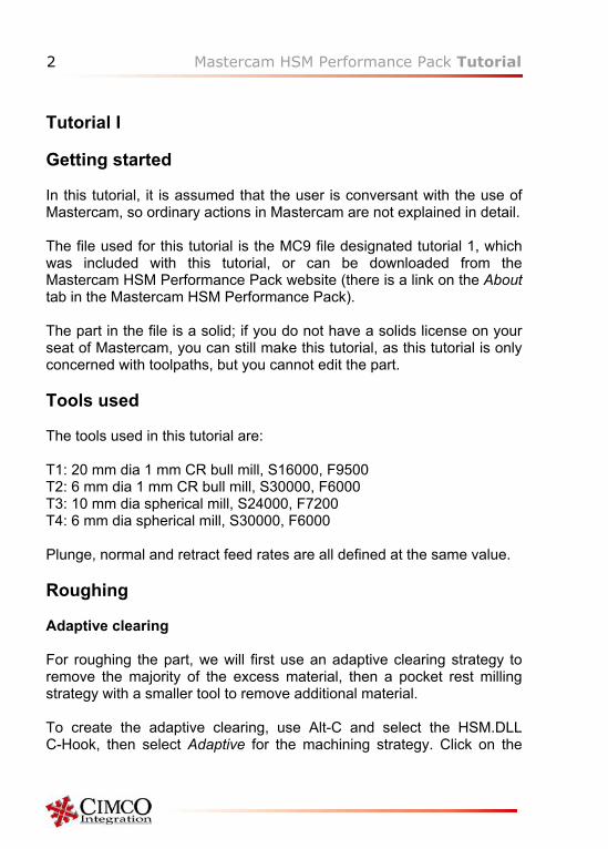
Tutorial I Getting started In this tutorial, it is assumed that the user is conversant with the use of Mastercam, so ordinary actions in Mastercam are not explained in detail. The file used for this tutorial is the MC9 file designated tutorial 1, which was included with this tutorial, or can be downloaded from the Mastercam HSM Performance Pack website (there is a link on the About tab in the Mastercam HSM Performance Pack). The part in the file is a solid; if you do not have a solids license on your seat of Mastercam, you can still make this tutorial, as this tutorial is only concerned with toolpaths, but you cannot edit the part. Tools used The tools used in this tutorial are: T1: 20 mm dia 1 mm CR bull mill, S16000, F9500 T2: 6 mm dia 1 mm CR bull mill, S30000, F6000 T3: 10 mm dia spherical mill, S24000, F7200 T4: 6 mm dia spherical mill, S30000, F6000 Plunge, normal and retract feed rates are all defined at the same value. Roughing Adaptive clearing For roughing the part, we will first use an adaptive clearing strategy to remove the majority of the excess material, then a pocket rest milling strategy with a smaller tool to remove additional material. To create the adaptive clearing, use Alt-C and select the HSM.DLL C-Hook, then select Adaptive for the machining strategy. Click on the
Mastercam HSM Performance Pack Tutorial 3
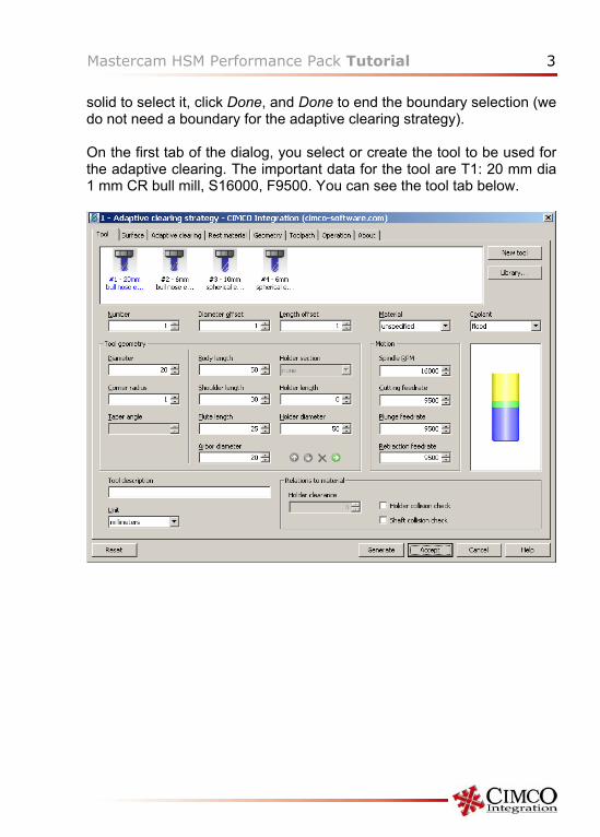
solid to select it, click Done, and Done to end the boundary selection (we do not need a boundary for the adaptive clearing strategy). On the first tab of the dialog, you select or create the tool to be used for the adaptive clearing. The important data for the tool are T1: 20 mm dia 1 mm CR bull mill, S16000, F9500. You can see the tool tab below.
4 Mastercam HSM Performance Pack Tutorial
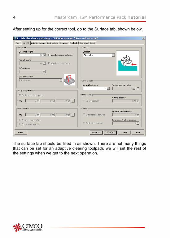
After setting up for the correct tool, go to the Surface tab, shown below.
The surface tab should be filled in as shown. There are not many things that can be set for an adaptive clearing toolpath, we will set the rest of the settings when we get to the next operation.
Mastercam HSM Performance Pack Tutorial 5
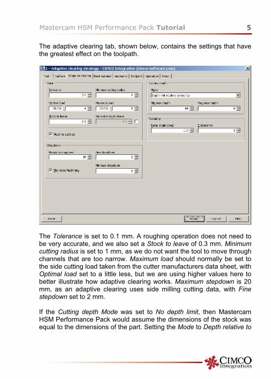
The adaptive clearing tab, shown below, contains the settings that have the greatest effect on the toolpath.
The Tolerance is set to 0.1 mm. A roughing operation does not need to be very accurate, and we also set a Stock to leave of 0.3 mm. Minimum cutting radius is set to 1 mm, as we do not want the tool to move through channels that are too narrow. Maximum load should normally be set to the side cutting load taken from the cutter manufacturers data sheet, with Optimal load set to a little less, but we are using higher values here to better illustrate how adaptive clearing works. Maximum stepdown is 20 mm, as an adaptive clearing uses side milling cutting data, with Fine stepdown set to 2 mm. If the Cutting depth Mode was set to No depth limit, then Mastercam HSM Performance Pack would assume the dimensions of the stock was equal to the dimensions of the part. Setting the Mode to Depth relative to
6 Mastercam HSM Performance Pack Tutorial
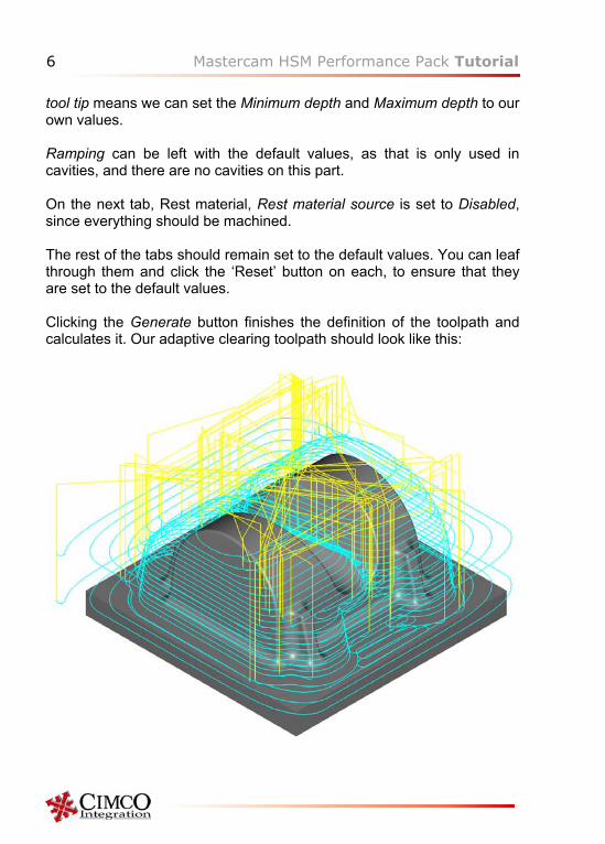
tool tip means we can set the Minimum depth and Maximum depth to our own values. Ramping can be left with the default values, as that is only used in cavities, and there are no cavities on this part. On the next tab, Rest material, Rest material source is set to Disabled, since everything should be machined. The rest of the tabs should remain set to the default values. You can leaf through them and click the ‘Reset’ button on each, to ensure that they are set to the default values. Clicking the Generate button finishes the definition of the toolpath and calculates it. Our adaptive clearing toolpath should look like this:
Mastercam HSM Performance Pack Tutorial 7
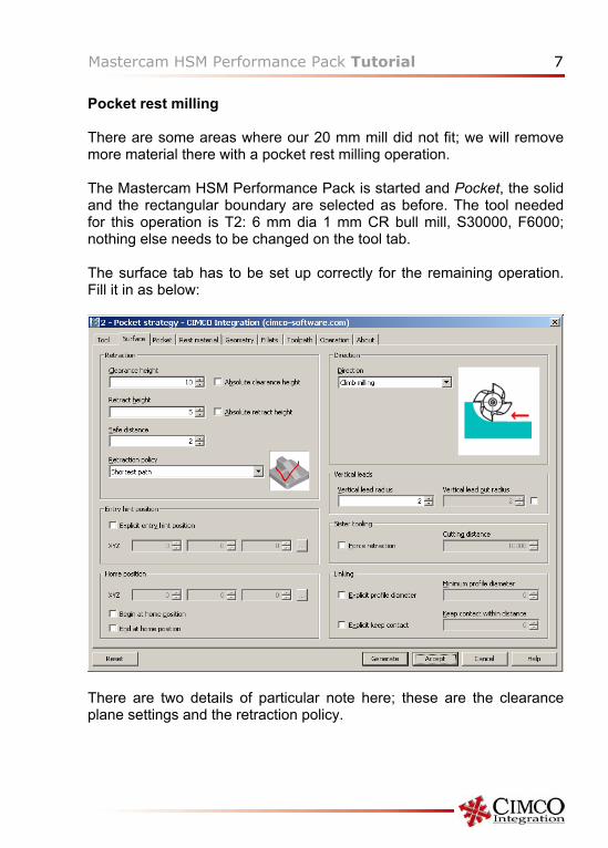
Pocket rest milling There are some areas where our 20 mm mill did not fit; we will remove more material there with a pocket rest milling operation. The Mastercam HSM Performance Pack is started and Pocket, the solid and the rectangular boundary are selected as before. The tool needed for this operation is T2: 6 mm dia 1 mm CR bull mill, S30000, F6000; nothing else needs to be changed on the tool tab. The surface tab has to be set up correctly for the remaining operation. Fill it in as below:
There are two details of particular note here; these are the clearance plane settings and the retraction policy.
8 Mastercam HSM Performance Pack Tutorial
For the clearance plane, we have set 10 mm, Absolute clearance not checked. This means that the clearance plane is 10 mm above the highest part of the selected geometry, and that gives a correct clearance plane for this part. In 3D machining, the clearance plane is often set to an absolute value (i.e. Absolute clearance should be checked), known to be above the part, while in 5 axis positioning (also called 3+2 axis machining), it is most often set to a relative clearance plane as here, as that is easier than calculating an absolute clearance plane in the rotated coordinate system. For this tutorial, the retraction policy is set to Shortest path (and on the toolpath tab, Rapid filtering is set to Preserve rapid motion). This gives the shortest possible rapid movement paths, but those settings can only be used on machines where rapid motion is interpolated as linear moves. Should you wish to machine the tutorial part on your machine, you may have to change those settings to suit your machine and control.
Mastercam HSM Performance Pack Tutorial 9
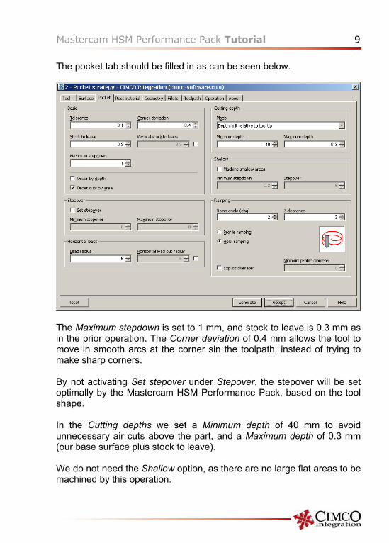
The pocket tab should be filled in as can be seen below.
The Maximum stepdown is set to 1 mm, and stock to leave is 0.3 mm as in the prior operation. The Corner deviation of 0.4 mm allows the tool to move in smooth arcs at the corner sin the toolpath, instead of trying to make sharp corners. By not activating Set stepover under Stepover, the stepover will be set optimally by the Mastercam HSM Performance Pack, based on the tool shape. In the Cutting depths we set a Minimum depth of 40 mm to avoid unnecessary air cuts above the part, and a Maximum depth of 0.3 mm (our base surface plus stock to leave). We do not need the Shallow option, as there are no large flat areas to be machined by this operation.
10 Mastercam HSM Performance Pack Tutorial
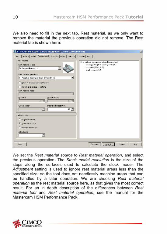
We also need to fill in the next tab, Rest material, as we only want to remove the material the previous operation did not remove. The Rest material tab is shown here:
We set the Rest material source to Rest material operation, and select the previous operation. The Stock model resolution is the size of the steps along the surfaces used to calculate the stock model. The Adjustment setting is used to ignore rest material areas less than the specified size, so the tool does not needlessly machine areas that can be handled by a later operation. We are choosing Rest material operation as the rest material source here, as that gives the most correct result. For an in depth description of the differences between Rest material tool and Rest material operation, see the manual for the Mastercam HSM Performance Pack.
Mastercam HSM Performance Pack Tutorial 11
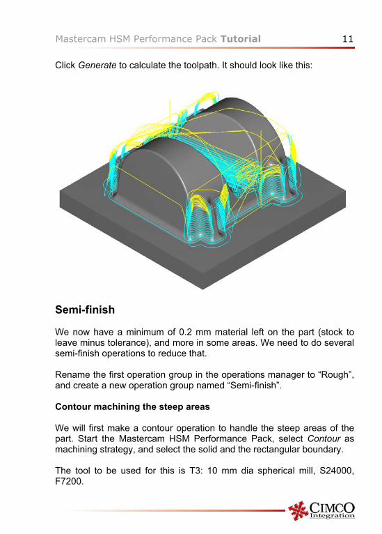
Click Generate to calculate the toolpath. It should look like this:
Semi-finish We now have a minimum of 0.2 mm material left on the part (stock to leave minus tolerance), and more in some areas. We need to do several semi-finish operations to reduce that. Rename the first operation group in the operations manager to “Rough”, and create a new operation group named “Semi-finish”. Contour machining the steep areas We will first make a contour operation to handle the steep areas of the part. Start the Mastercam HSM Performance Pack, select Contour as machining strategy, and select the solid and the rectangular boundary.
The tool to be used for this is T3: 10 mm dia spherical mill, S24000, F7200.
12 Mastercam HSM Performance Pack Tutorial
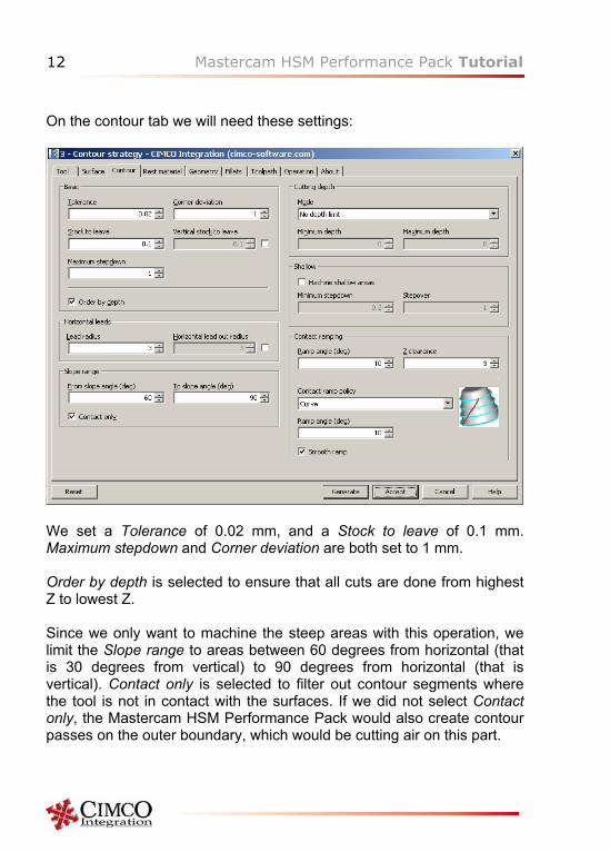
On the contour tab we will need these settings:
We set a Tolerance of 0.02 mm, and a Stock to leave of 0.1 mm. Maximum stepdown and Corner deviation are both set to 1 mm. Order by depth is selected to ensure that all cuts are done from highest Z to lowest Z. Since we only want to machine the steep areas with this operation, we limit the Slope range to areas between 60 degrees from horizontal (that is 30 degrees from vertical) to 90 degrees from horizontal (that is vertical). Contact only is selected to filter out contour segments where the tool is not in contact with the surfaces. If we did not select Contact only, the Mastercam HSM Performance Pack would also create contour passes on the outer boundary, which would be cutting air on this part.
Mastercam HSM Performance Pack Tutorial 13
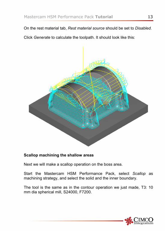
On the rest material tab, Rest material source should be set to Disabled. Click Generate to calculate the toolpath. It should look like this:
Scallop machining the shallow areas Next we will make a scallop operation on the boss area. Start the Mastercam HSM Performance Pack, select Scallop as machining strategy, and select the solid and the inner boundary. The tool is the same as in the contour operation we just made, T3: 10 mm dia spherical mill, S24000, F7200.
14 Mastercam HSM Performance Pack Tutorial
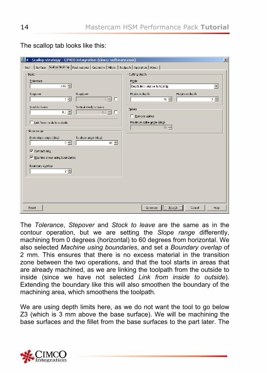
The scallop tab looks like this:
The Tolerance, Stepover and Stock to leave are the same as in the contour operation, but we are setting the Slope range differently, machining from 0 degrees (horizontal) to 60 degrees from horizontal. We also selected Machine using boundaries, and set a Boundary overlap of 2 mm. This ensures that there is no excess material in the transition zone between the two operations, and that the tool starts in areas that are already machined, as we are linking the toolpath from the outside to inside (since we have not selected Link from inside to outside). Extending the boundary like this will also smoothen the boundary of the machining area, which smoothens the toolpath. We are using depth limits here, as we do not want the tool to go below Z3 (which is 3 mm above the base surface). We will be machining the base surfaces and the fillet from the base surfaces to the part later. The
Mastercam HSM Performance Pack Tutorial 15
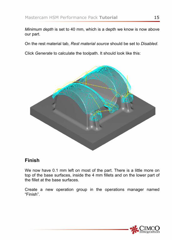
Minimum depth is set to 40 mm, which is a depth we know is now above our part. On the rest material tab, Rest material source should be set to Disabled. Click Generate to calculate the toolpath. It should look like this:
Finish We now have 0.1 mm left on most of the part. There is a little more on top of the base surfaces, inside the 4 mm fillets and on the lower part of the fillet at the base surfaces. Create a new operation group in the operations manager named “Finish”.
16 Mastercam HSM Performance Pack Tutorial
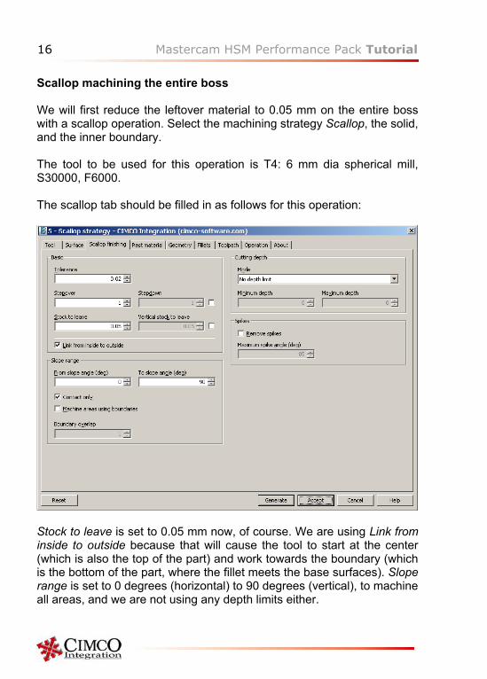
Scallop machining the entire boss We will first reduce the leftover material to 0.05 mm on the entire boss with a scallop operation. Select the machining strategy Scallop, the solid, and the inner boundary. The tool to be used for this operation is T4: 6 mm dia spherical mill, S30000, F6000. The scallop tab should be filled in as follows for this operation:
Stock to leave is set to 0.05 mm now, of course. We are using Link from inside to outside because that will cause the tool to start at the center (which is also the top of the part) and work towards the boundary (which is the bottom of the part, where the fillet meets the base surfaces). Slope range is set to 0 degrees (horizontal) to 90 degrees (vertical), to machine all areas, and we are not using any depth limits either.
Mastercam HSM Performance Pack Tutorial 17
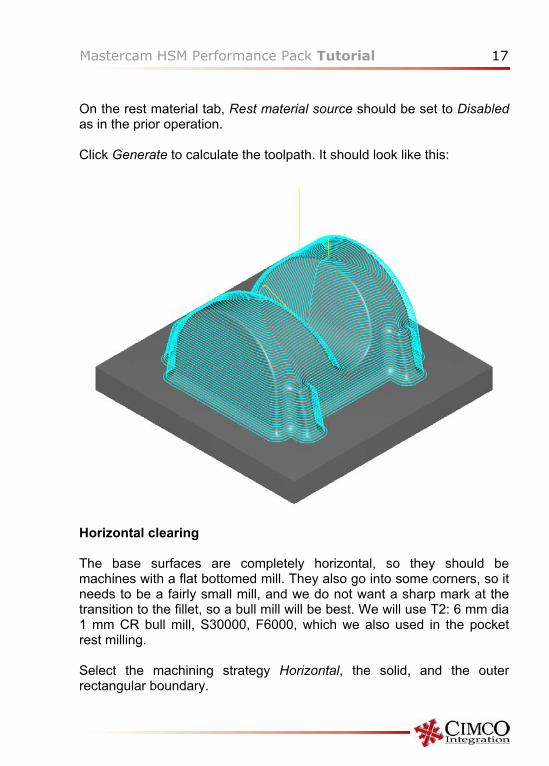
On the rest material tab, Rest material source should be set to Disabled as in the prior operation. Click Generate to calculate the toolpath. It should look like this:
Horizontal clearing The base surfaces are completely horizontal, so they should be machines with a flat bottomed mill. They also go into some corners, so it needs to be a fairly small mill, and we do not want a sharp mark at the transition to the fillet, so a bull mill will be best. We will use T2: 6 mm dia 1 mm CR bull mill, S30000, F6000, which we also used in the pocket rest milling. Select the machining strategy Horizontal, the solid, and the outer rectangular boundary.
18 Mastercam HSM Performance Pack Tutorial
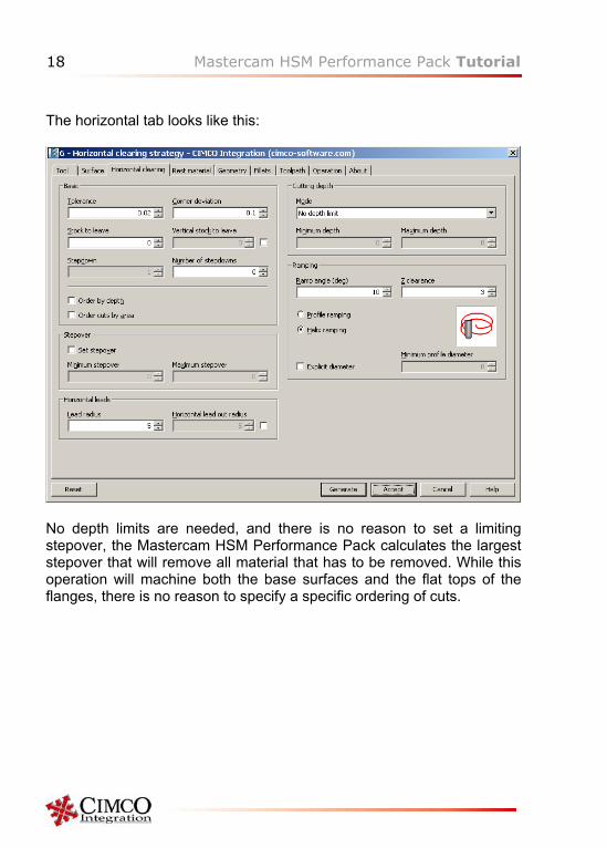
The horizontal tab looks like this:
No depth limits are needed, and there is no reason to set a limiting stepover, the Mastercam HSM Performance Pack calculates the largest stepover that will remove all material that has to be removed. While this operation will machine both the base surfaces and the flat tops of the flanges, there is no reason to specify a specific ordering of cuts.
Mastercam HSM Performance Pack Tutorial 19
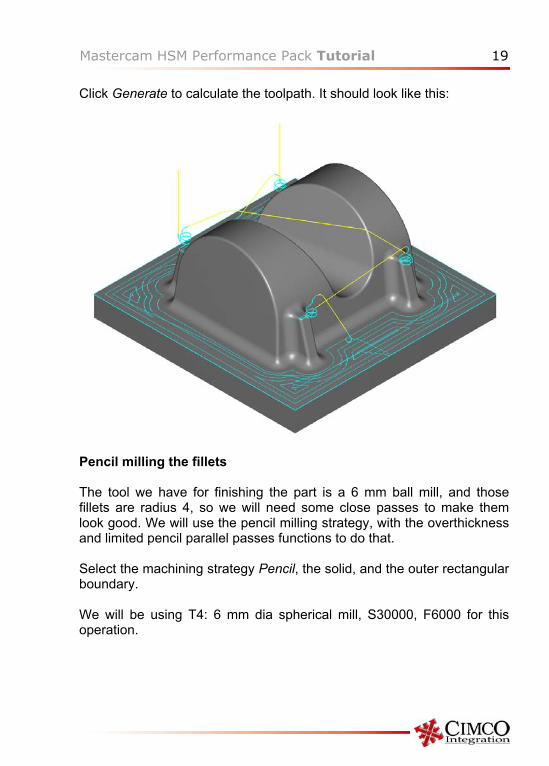
Click Generate to calculate the toolpath. It should look like this:
Pencil milling the fillets The tool we have for finishing the part is a 6 mm ball mill, and those fillets are radius 4, so we will need some close passes to make them look good. We will use the pencil milling strategy, with the overthickness and limited pencil parallel passes functions to do that. Select the machining strategy Pencil, the solid, and the outer rectangular boundary. We will be using T4: 6 mm dia spherical mill, S30000, F6000 for this operation.
20 Mastercam HSM Performance Pack Tutorial
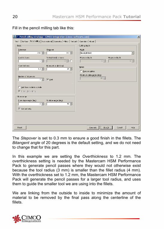
Fill in the pencil milling tab like this:
The Stepover is set to 0.3 mm to ensure a good finish in the fillets. The Bitangent angle of 20 degrees is the default setting, and we do not need to change that for this part. In this example we are setting the Overthickness to 1.2 mm. The overthickness setting is needed by the Mastercam HSM Performance Pack to generate pencil passes where they would not otherwise exist because the tool radius (3 mm) is smaller than the fillet radius (4 mm). With the overthickness set to 1.2 mm, the Mastercam HSM Performance Pack will generate the pencil passes for a larger tool radius, and uses them to guide the smaller tool we are using into the fillets. We are linking from the outside to inside to minimize the amount of material to be removed by the final pass along the centerline of the fillets.
Mastercam HSM Performance Pack Tutorial 21
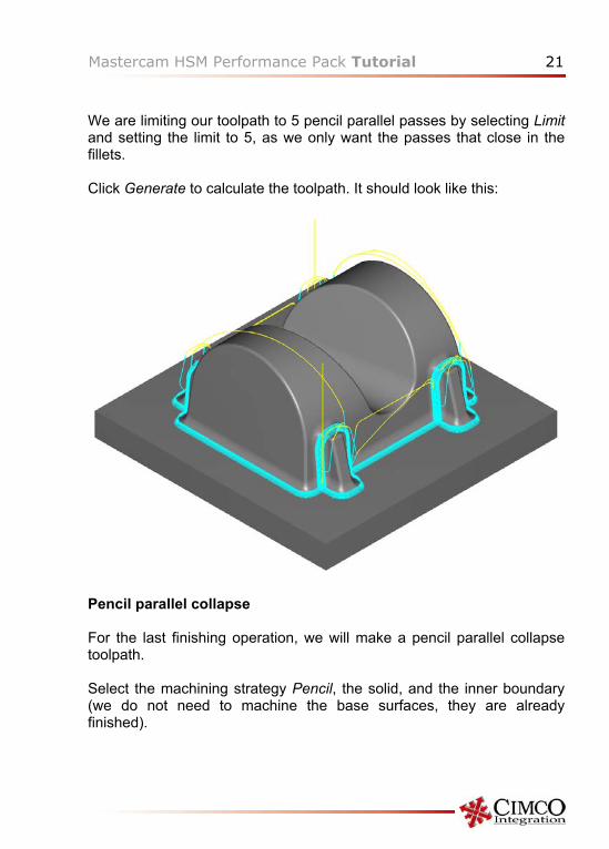
We are limiting our toolpath to 5 pencil parallel passes by selecting Limit and setting the limit to 5, as we only want the passes that close in the fillets. Click Generate to calculate the toolpath. It should look like this:
Pencil parallel collapse For the last finishing operation, we will make a pencil parallel collapse toolpath. Select the machining strategy Pencil, the solid, and the inner boundary (we do not need to machine the base surfaces, they are already finished).
22 Mastercam HSM Performance Pack Tutorial
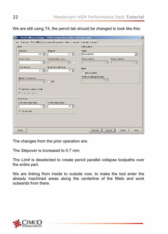
We are still using T4, the pencil tab should be changed to look like this:
The changes from the prior operation are: The Stepover is increased to 0.7 mm. The Limit is deselected to create pencil parallel collapse toolpaths over the entire part. We are linking from inside to outside now, to make the tool enter the already machined areas along the centerline of the fillets and work outwards from there.
Mastercam HSM Performance Pack Tutorial 23
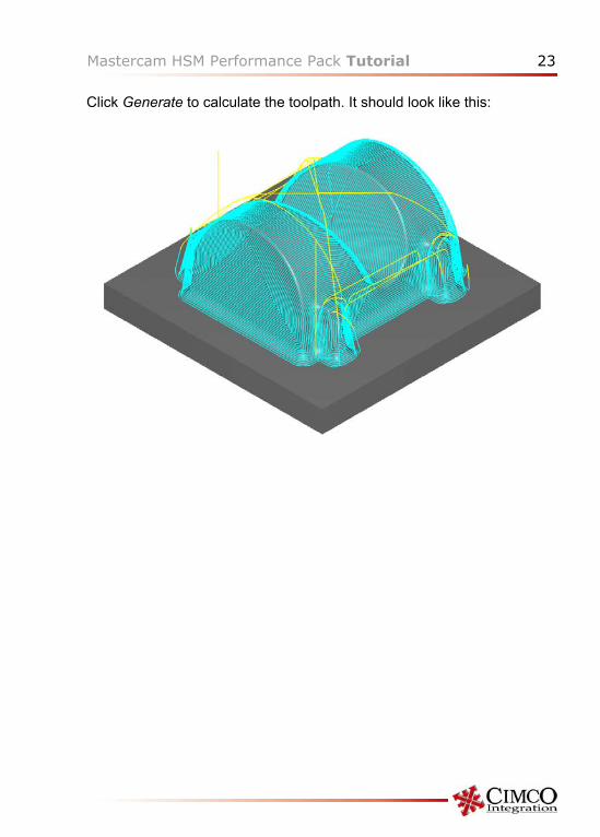
Click Generate to calculate the toolpath. It should look like this:
24 Mastercam HSM Performance Pack Tutorial
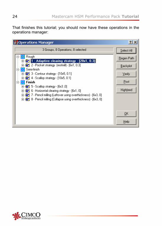
That finishes this tutorial; you should now have these operations in the operations manager:
Mastercam HSM Performance Pack Tutorial 25
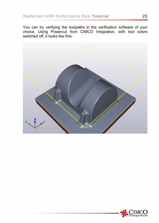
You can try verifying the toolpaths in the verification software of your choice. Using Powercut from CIMCO Integration, with tool colors switched off, it looks like this:
26 Mastercam HSM Performance Pack Tutorial
Tutorial II Getting Started In this tutorial, it is assumed that the user is conversant with the use of Mastercam, so ordinary actions in Mastercam are not explained in detail. The file used for this tutorial is the MC9 file designated tutorial 2, which was included with this tutorial, or can be downloaded from the Mastercam HSM Performance Pack website (there is a link on the About tab in the Mastercam HSM Performance Pack). The part in the file is a solid; If you do not have a solids license on your seat of Mastercam, you can still make this tutorial, as this tutorial is only concerned with toolpaths, but you cannot edit the part. Tools used The tools used in this tutorial are: T1: 10 mm dia 1 mm CR bull mill, S9550, Plunge feed F1900, Cutting and retract feed F3820 T2: 3 mm dia 0.5 mm CR bull mill, S30000, Plunge feed F1800, Cutting and retract feed F3600 T3: 2 mm dia spherical mill, S30000, Plunge feed F900, Cutting and retract feed F1800 T4: 3 mm dia spherical mill, S30000, Plunge feed F1800, Cutting and retract feed F3600 T5: 4 mm dia 0.5 mm CR bull mill, S23800, Plunge feed F1500, Cutting and retract feed F2860 T6: 1 mm dia spherical mill, S30000, Plunge feed F400, Cutting and retract feed F900
Mastercam HSM Performance Pack Tutorial 27
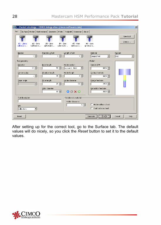
Roughing Pocket roughing For roughing the part, we will first use a normal pocket strategy to remove the majority of the excess material, then a pocket rest milling strategy with a smaller tool to remove additional material. To create the pocket toolpath, use Alt-C and select the HSM.DLL C-Hook, then select Pocket for the machining strategy. Click on the solid to select it, click Done, then you select the two outer boundaries (check that the chaining method is “Full”), and Done to end the boundary selection. On the first tab of the dialog, you select or create the tool to be used for the pocket operation. The important data for the tool are T1: 10 mm dia 1 mm CR bull mill, S9550, Plunge feed F1900, Cutting and retract feed F3820. You can see the tool tab on next page.
28 Mastercam HSM Performance Pack Tutorial
After setting up for the correct tool, go to the Surface tab. The default values will do nicely, so you click the Reset button to set it to the default values.
Mastercam HSM Performance Pack Tutorial 29
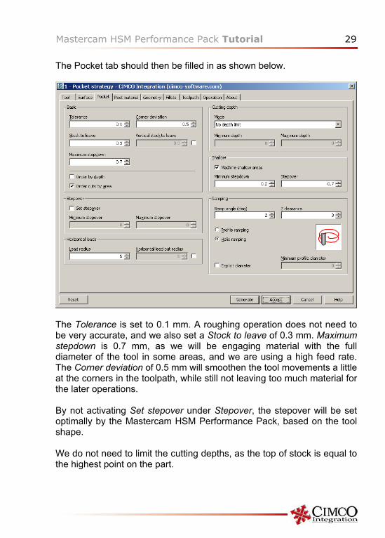
The Pocket tab should then be filled in as shown below.
The Tolerance is set to 0.1 mm. A roughing operation does not need to be very accurate, and we also set a Stock to leave of 0.3 mm. Maximum stepdown is 0.7 mm, as we will be engaging material with the full diameter of the tool in some areas, and we are using a high feed rate. The Corner deviation of 0.5 mm will smoothen the tool movements a little at the corners in the toolpath, while still not leaving too much material for the later operations. By not activating Set stepover under Stepover, the stepover will be set optimally by the Mastercam HSM Performance Pack, based on the tool shape. We do not need to limit the cutting depths, as the top of stock is equal to the highest point on the part.
30 Mastercam HSM Performance Pack Tutorial
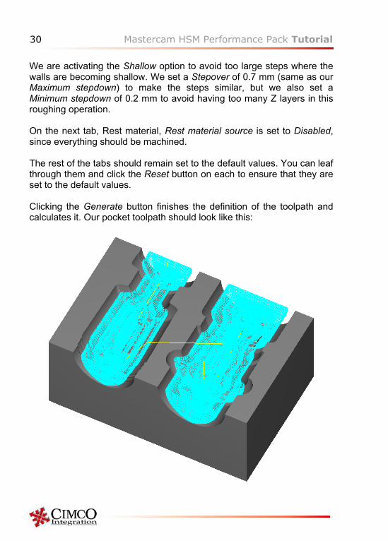
We are activating the Shallow option to avoid too large steps where the walls are becoming shallow. We set a Stepover of 0.7 mm (same as our Maximum stepdown) to make the steps similar, but we also set a Minimum stepdown of 0.2 mm to avoid having too many Z layers in this roughing operation. On the next tab, Rest material, Rest material source is set to Disabled, since everything should be machined. The rest of the tabs should remain set to the default values. You can leaf through them and click the Reset button on each to ensure that they are set to the default values. Clicking the Generate button finishes the definition of the toolpath and calculates it. Our pocket toolpath should look like this:
Mastercam HSM Performance Pack Tutorial 31
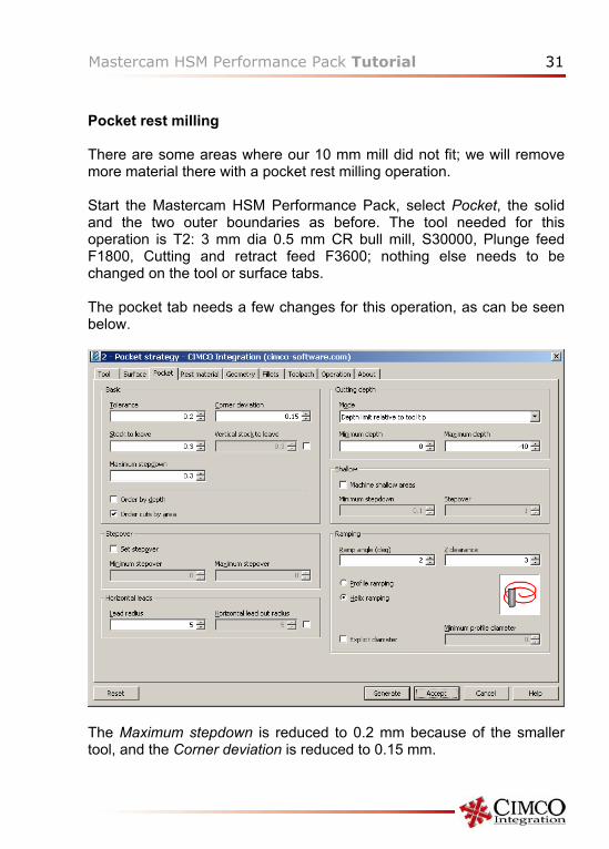
Pocket rest milling There are some areas where our 10 mm mill did not fit; we will remove more material there with a pocket rest milling operation. Start the Mastercam HSM Performance Pack, select Pocket, the solid and the two outer boundaries as before. The tool needed for this operation is T2: 3 mm dia 0.5 mm CR bull mill, S30000, Plunge feed F1800, Cutting and retract feed F3600; nothing else needs to be changed on the tool or surface tabs. The pocket tab needs a few changes for this operation, as can be seen below.
The Maximum stepdown is reduced to 0.2 mm because of the smaller tool, and the Corner deviation is reduced to 0.15 mm.
32 Mastercam HSM Performance Pack Tutorial
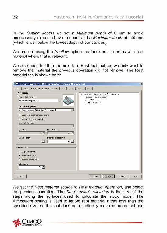
In the Cutting depths we set a Minimum depth of 0 mm to avoid unnecessary air cuts above the part, and a Maximum depth of –40 mm (which is well below the lowest depth of our cavities). We are not using the Shallow option, as there are no areas with rest material where that is relevant. We also need to fill in the next tab, Rest material, as we only want to remove the material the previous operation did not remove. The Rest material tab is shown here:
We set the Rest material source to Rest material operation, and select the previous operation. The Stock model resolution is the size of the steps along the surfaces used to calculate the stock model. The Adjustment setting is used to ignore rest material areas less than the specified size, so the tool does not needlessly machine areas that can
Mastercam HSM Performance Pack Tutorial 33
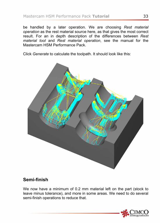
be handled by a later operation. We are choosing Rest material operation as the rest material source here, as that gives the most correct result. For an in depth description of the differences between Rest material tool and Rest material operation, see the manual for the Mastercam HSM Performance Pack. Click Generate to calculate the toolpath. It should look like this:
Semi-finish We now have a minimum of 0.2 mm material left on the part (stock to leave minus tolerance), and more in some areas. We need to do several semi-finish operations to reduce that.
34 Mastercam HSM Performance Pack Tutorial
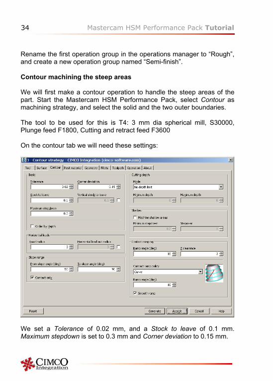
Rename the first operation group in the operations manager to “Rough”, and create a new operation group named “Semi-finish”. Contour machining the steep areas We will first make a contour operation to handle the steep areas of the part. Start the Mastercam HSM Performance Pack, select Contour as machining strategy, and select the solid and the two outer boundaries. The tool to be used for this is T4: 3 mm dia spherical mill, S30000, Plunge feed F1800, Cutting and retract feed F3600 On the contour tab we will need these settings:
We set a Tolerance of 0.02 mm, and a Stock to leave of 0.1 mm. Maximum stepdown is set to 0.3 mm and Corner deviation to 0.15 mm.
Mastercam HSM Performance Pack Tutorial 35
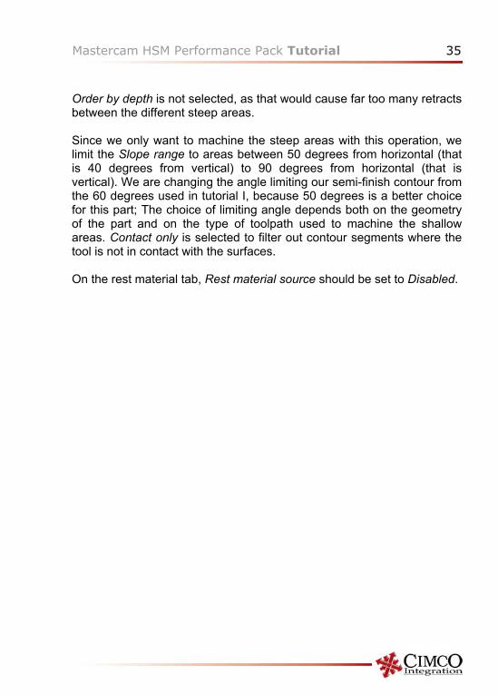
Order by depth is not selected, as that would cause far too many retracts between the different steep areas. Since we only want to machine the steep areas with this operation, we limit the Slope range to areas between 50 degrees from horizontal (that is 40 degrees from vertical) to 90 degrees from horizontal (that is vertical). We are changing the angle limiting our semi-finish contour from the 60 degrees used in tutorial I, because 50 degrees is a better choice for this part; The choice of limiting angle depends both on the geometry of the part and on the type of toolpath used to machine the shallow areas. Contact only is selected to filter out contour segments where the tool is not in contact with the surfaces. On the rest material tab, Rest material source should be set to Disabled.
36 Mastercam HSM Performance Pack Tutorial
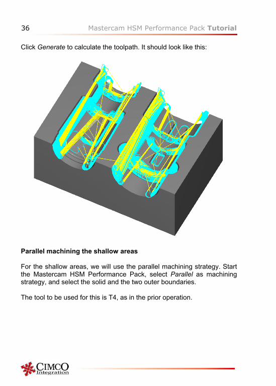
Click Generate to calculate the toolpath. It should look like this:
Parallel machining the shallow areas For the shallow areas, we will use the parallel machining strategy. Start the Mastercam HSM Performance Pack, select Parallel as machining strategy, and select the solid and the two outer boundaries. The tool to be used for this is T4, as in the prior operation.
Mastercam HSM Performance Pack Tutorial 37
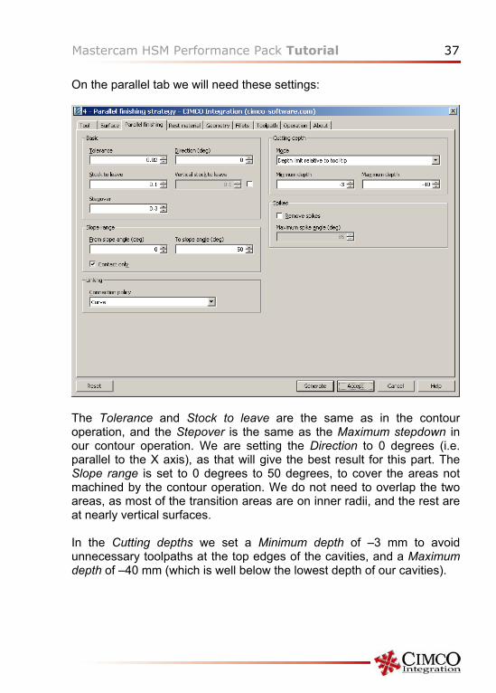
On the parallel tab we will need these settings:
The Tolerance and Stock to leave are the same as in the contour operation, and the Stepover is the same as the Maximum stepdown in our contour operation. We are setting the Direction to 0 degrees (i.e. parallel to the X axis), as that will give the best result for this part. The Slope range is set to 0 degrees to 50 degrees, to cover the areas not machined by the contour operation. We do not need to overlap the two areas, as most of the transition areas are on inner radii, and the rest are at nearly vertical surfaces. In the Cutting depths we set a Minimum depth of –3 mm to avoid unnecessary toolpaths at the top edges of the cavities, and a Maximum depth of –40 mm (which is well below the lowest depth of our cavities).
38 Mastercam HSM Performance Pack Tutorial
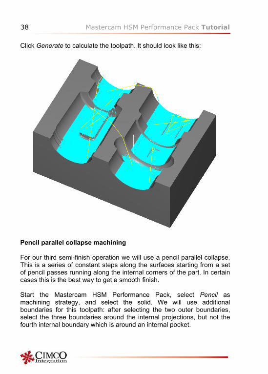
Click Generate to calculate the toolpath. It should look like this:
Pencil parallel collapse machining For our third semi-finish operation we will use a pencil parallel collapse. This is a series of constant steps along the surfaces starting from a set of pencil passes running along the internal corners of the part. In certain cases this is the best way to get a smooth finish. Start the Mastercam HSM Performance Pack, select Pencil as machining strategy, and select the solid. We will use additional boundaries for this toolpath: after selecting the two outer boundaries, select the three boundaries around the internal projections, but not the fourth internal boundary which is around an internal pocket.
Mastercam HSM Performance Pack Tutorial 39
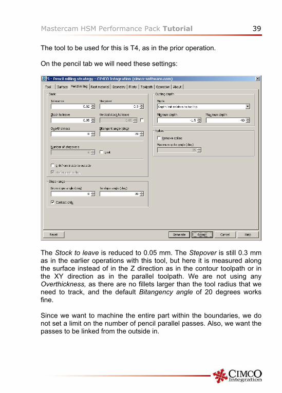
The tool to be used for this is T4, as in the prior operation. On the pencil tab we will need these settings:
The Stock to leave is reduced to 0.05 mm. The Stepover is still 0.3 mm as in the earlier operations with this tool, but here it is measured along the surface instead of in the Z direction as in the contour toolpath or in the XY direction as in the parallel toolpath. We are not using any Overthickness, as there are no fillets larger than the tool radius that we need to track, and the default Bitangency angle of 20 degrees works fine. Since we want to machine the entire part within the boundaries, we do not set a limit on the number of pencil parallel passes. Also, we want the passes to be linked from the outside in.
40 Mastercam HSM Performance Pack Tutorial
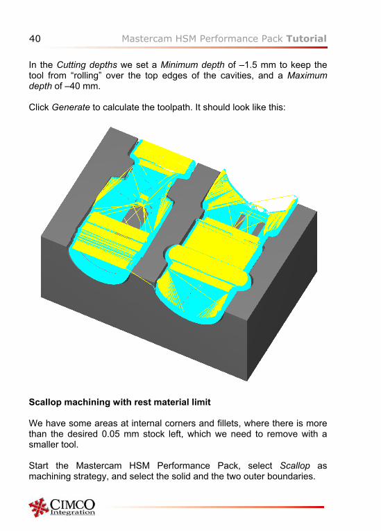
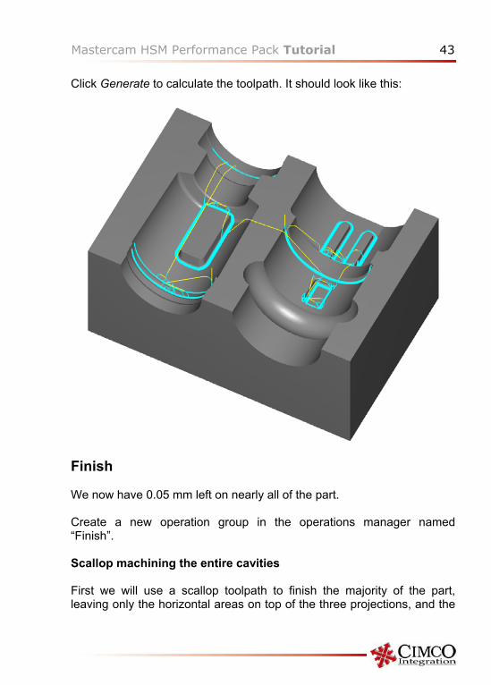
In the Cutting depths we set a Minimum depth of –1.5 mm to keep the tool from “rolling” over the top edges of the cavities, and a Maximum depth of –40 mm. Click Generate to calculate the toolpath. It should look like this:
Scallop machining with rest material limit We have some areas at internal corners and fillets, where there is more than the desired 0.05 mm stock left, which we need to remove with a smaller tool. Start the Mastercam HSM Performance Pack, select Scallop as machining strategy, and select the solid and the two outer boundaries.
Mastercam HSM Performance Pack Tutorial 41
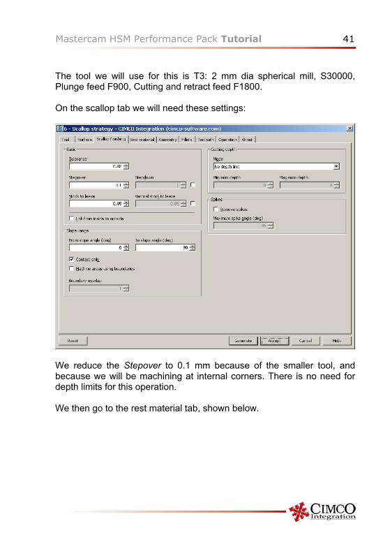
The tool we will use for this is T3: 2 mm dia spherical mill, S30000, Plunge feed F900, Cutting and retract feed F1800. On the scallop tab we will need these settings:
We reduce the Stepover to 0.1 mm because of the smaller tool, and because we will be machining at internal corners. There is no need for depth limits for this operation. We then go to the rest material tab, shown below.
42 Mastercam HSM Performance Pack Tutorial
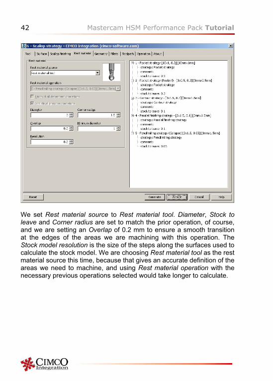
We set Rest material source to Rest material tool. Diameter, Stock to leave and Corner radius are set to match the prior operation, of course, and we are setting an Overlap of 0.2 mm to ensure a smooth transition at the edges of the areas we are machining with this operation. The Stock model resolution is the size of the steps along the surfaces used to calculate the stock model. We are choosing Rest material tool as the rest material source this time, because that gives an accurate definition of the areas we need to machine, and using Rest material operation with the necessary previous operations selected would take longer to calculate.
Mastercam HSM Performance Pack Tutorial 43
Click Generate to calculate the toolpath. It should look like this:
Finish We now have 0.05 mm left on nearly all of the part. Create a new operation group in the operations manager named “Finish”. Scallop machining the entire cavities First we will use a scallop toolpath to finish the majority of the part, leaving only the horizontal areas on top of the three projections, and the
44 Mastercam HSM Performance Pack Tutorial
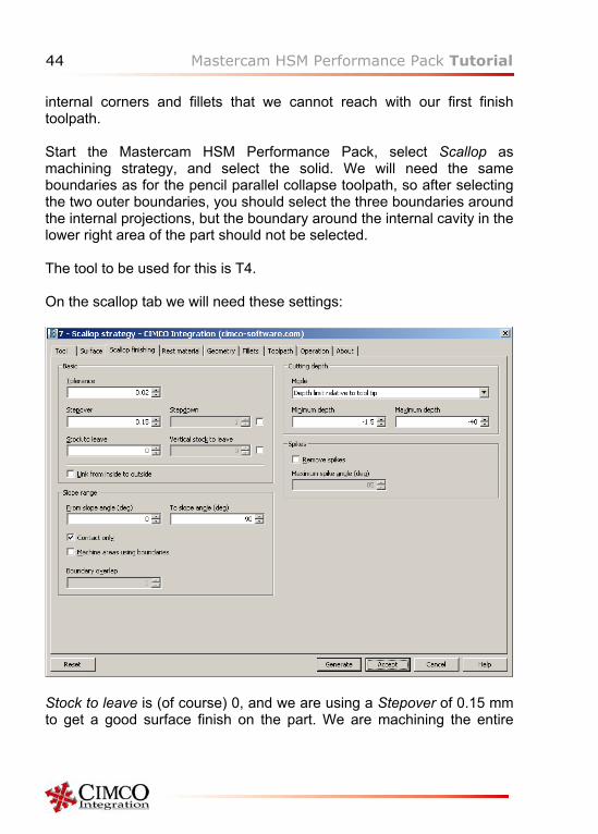
internal corners and fillets that we cannot reach with our first finish toolpath. Start the Mastercam HSM Performance Pack, select Scallop as machining strategy, and select the solid. We will need the same boundaries as for the pencil parallel collapse toolpath, so after selecting the two outer boundaries, you should select the three boundaries around the internal projections, but the boundary around the internal cavity in the lower right area of the part should not be selected. The tool to be used for this is T4. On the scallop tab we will need these settings:
Stock to leave is (of course) 0, and we are using a Stepover of 0.15 mm to get a good surface finish on the part. We are machining the entire
Mastercam HSM Performance Pack Tutorial 45
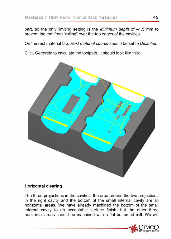
part, so the only limiting setting is the Minimum depth of –1.5 mm to prevent the tool from “rolling” over the top edges of the cavities. On the rest material tab, Rest material source should be set to Disabled. Click Generate to calculate the toolpath. It should look like this:
Horizontal clearing The three projections in the cavities, the area around the two projections in the right cavity and the bottom of the small internal cavity are all horizontal areas. We have already machined the bottom of the small internal cavity to an acceptable surface finish, but the other three horizontal areas should be machined with a flat bottomed mill. We will
46 Mastercam HSM Performance Pack Tutorial
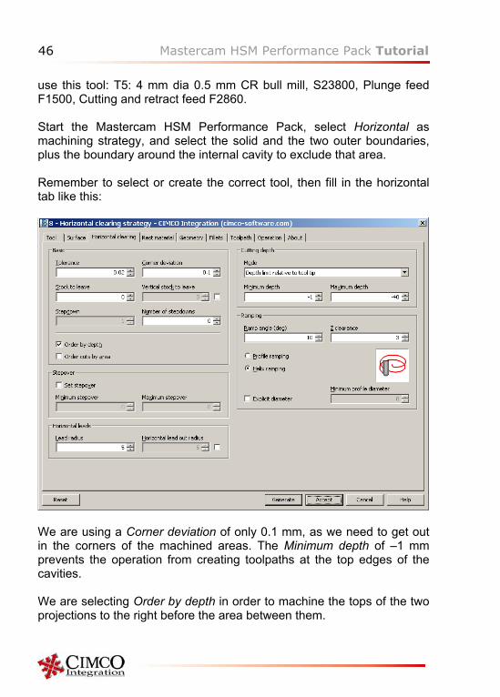
use this tool: T5: 4 mm dia 0.5 mm CR bull mill, S23800, Plunge feed F1500, Cutting and retract feed F2860. Start the Mastercam HSM Performance Pack, select Horizontal as machining strategy, and select the solid and the two outer boundaries, plus the boundary around the internal cavity to exclude that area. Remember to select or create the correct tool, then fill in the horizontal tab like this:
We are using a Corner deviation of only 0.1 mm, as we need to get out in the corners of the machined areas. The Minimum depth of –1 mm prevents the operation from creating toolpaths at the top edges of the cavities. We are selecting Order by depth in order to machine the tops of the two projections to the right before the area between them.
Mastercam HSM Performance Pack Tutorial 47
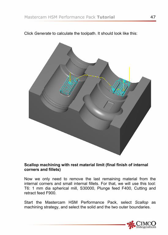
Click Generate to calculate the toolpath. It should look like this:
Scallop machining with rest material limit (final finish of internal corners and fillets) Now we only need to remove the last remaining material from the internal corners and small internal fillets. For that, we will use this tool: T6: 1 mm dia spherical mill, S30000, Plunge feed F400, Cutting and retract feed F900. Start the Mastercam HSM Performance Pack, select Scallop as machining strategy, and select the solid and the two outer boundaries.
48 Mastercam HSM Performance Pack Tutorial
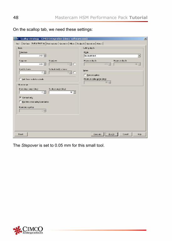
On the scallop tab, we need these settings:
The Stepover is set to 0.05 mm for this small tool.
Mastercam HSM Performance Pack Tutorial 49
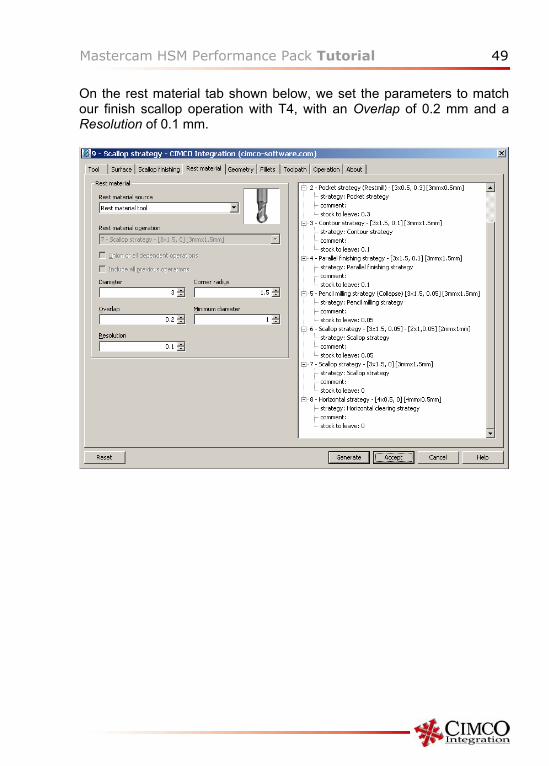
On the rest material tab shown below, we set the parameters to match our finish scallop operation with T4, with an Overlap of 0.2 mm and a Resolution of 0.1 mm.
50 Mastercam HSM Performance Pack Tutorial
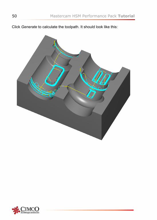
Click Generate to calculate the toolpath. It should look like this:
Mastercam HSM Performance Pack Tutorial 51
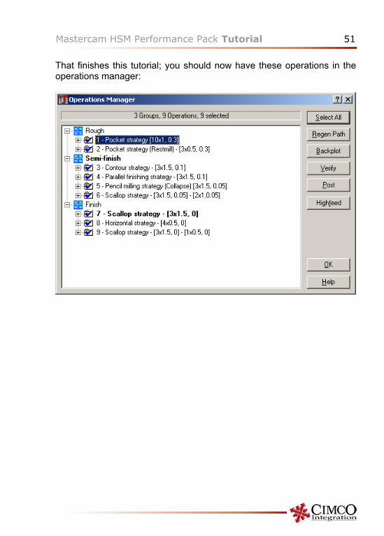
That finishes this tutorial; you should now have these operations in the operations manager:
52 Mastercam HSM Performance Pack Tutorial
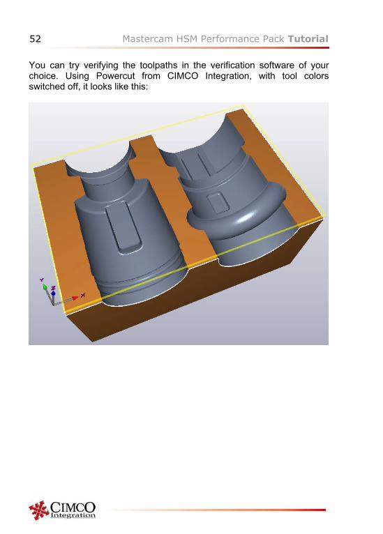
You can try verifying the toolpaths in the verification software of your choice. Using Powercut from CIMCO Integration, with tool colors switched off, it looks like this: