Embed Size (px)
Citation preview
Mastercam 2020 Skyhook Toolpath Page 3-1
Skyhook
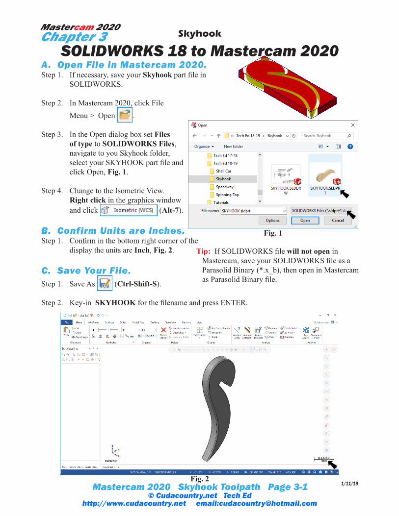
SOLIDWORKS 18 to Mastercam 2020A. Open File in Mastercam 2020.Step 1. If necessary, save your Skyhook part file in
SOLIDWORKS.
Step 2. In Mastercam 2020, click File Menu > Open .
Step 3. In the Open dialog box set Files of type to SOLIDWORKS Files, navigate to you Skyhook folder, select your SKYHOOK part file and click Open, Fig. 1.
Step 4. Change to the Isometric View. Right click in the graphics window and click (Alt-7).
B. Confirm Units are Inches.Step 1. Confirm in the bottom right corner of the
display the units are Inch, Fig. 2.
C. Save Your File.Step 1. Save As (Ctrl-Shift-S).
Step 2. Key-in SKYHOOK for the filename and press ENTER.
1/11/19
Mastercam 2020Chapter 3
Fig. 1
Fig. 2
Tip: If SOLIDWORKS file will not open in Mastercam, save your SOLIDWORKS file as a Parasolid Binary (*.x_b), then open in Mastercam as Parasolid Binary file.
© Cudacountry.net Tech Edhttp://www.cudacountry.net email:[email protected]
Mastercam 2020 Skyhook Toolpath Page 3-2
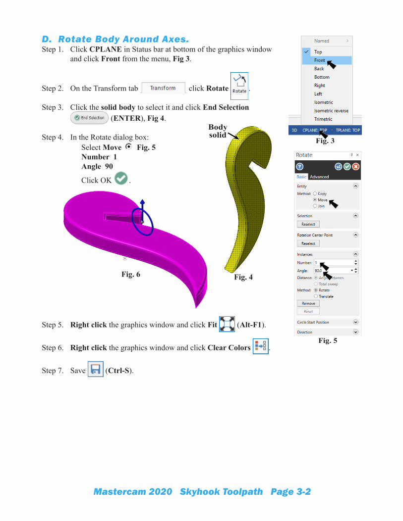
D. Rotate Body Around Axes.Step 1. Click CPLANE in Status bar at bottom of the graphics window
and click Front from the menu, Fig 3.
Step 2. On the Transform tab click Rotate .
Step 3. Click the solid body to select it and click End Selection (ENTER), Fig 4.
Step 4. In the Rotate dialog box: Select Move Fig. 5 Number 1 Angle 90
Click OK .
Step 5. Right click the graphics window and click Fit (Alt-F1).
Step 6. Right click the graphics window and click Clear Colors .
Step 7. Save (Ctrl-S).
Fig. 3
Body solid
Fig. 4Fig. 6
Fig. 5
Mastercam 2020 Skyhook Toolpath Page 3-3
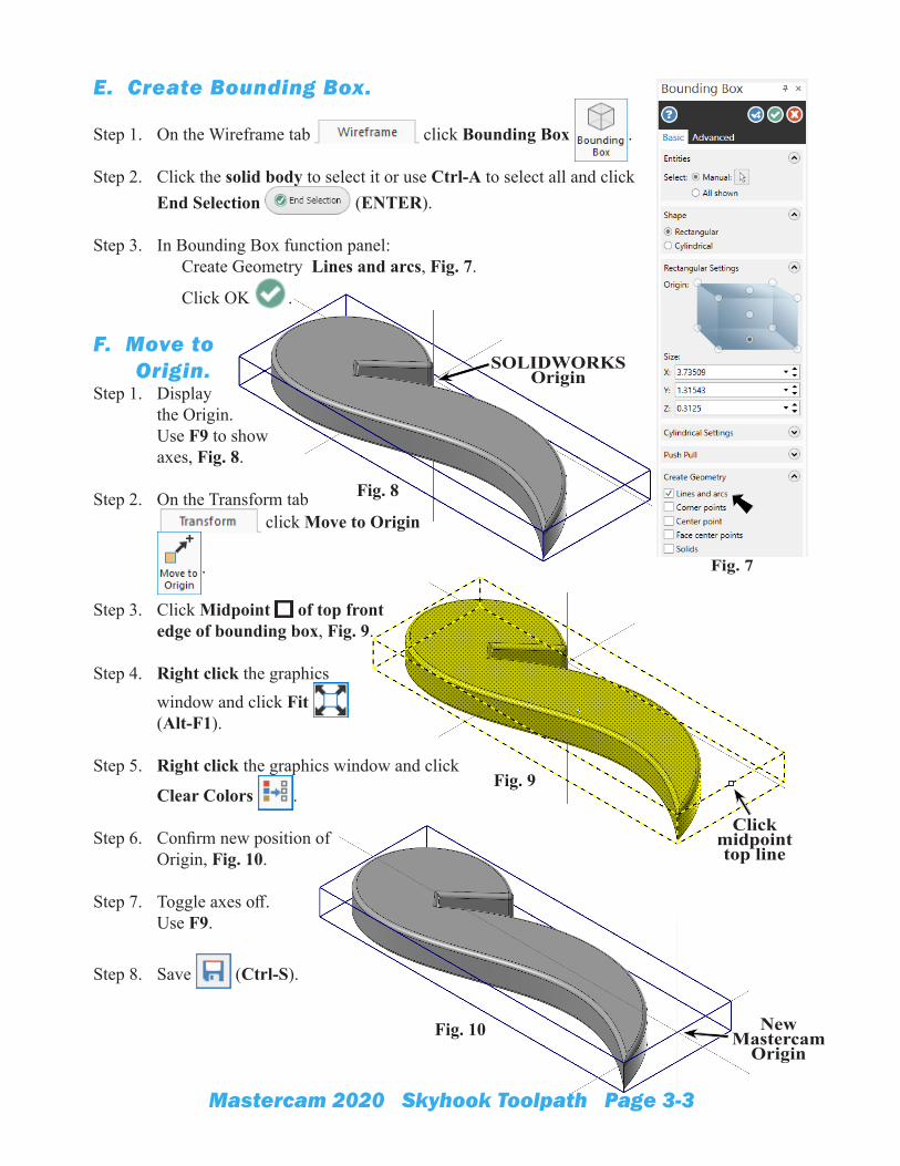
E. Create Bounding Box.
Step 1. On the Wireframe tab click Bounding Box .
Step 2. Click the solid body to select it or use Ctrl-A to select all and click End Selection (ENTER).
Step 3. In Bounding Box function panel: Create Geometry Lines and arcs, Fig. 7.
Click OK .
F. Move to Origin.
Step 1. Display the Origin. Use F9 to show axes, Fig. 8.
Step 2. On the Transform tab click Move to Origin
.
Step 3. Click Midpoint of top front edge of bounding box, Fig. 9.
Step 4. Right click the graphics window and click Fit (Alt-F1).
Step 5. Right click the graphics window and click
Clear Colors .
Step 6. Confirm new position of Origin, Fig. 10.
Step 7. Toggle axes off. Use F9.
Step 8. Save (Ctrl-S).
Fig. 7
Fig. 8
Fig. 9
Fig. 10
SOLIDWORKS Origin
Click midpoint top line
New Mastercam
Origin
Mastercam 2020 Skyhook Toolpath Page 3-4
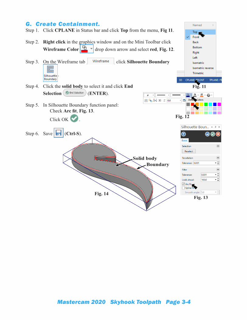
G. Create Containment.Step 1. Click CPLANE in Status bar and click Top from the menu, Fig 11.
Step 2. Right click in the graphics window and on the Mini Toolbar click Wireframe Color drop down arrow and select red, Fig. 12.
Step 3. On the Wireframe tab click Silhouette Boundary
.
Step 4. Click the solid body to select it and click End Selection (ENTER).
Step 5. In Silhouette Boundary function panel: Check Arc fit, Fig. 13.
Click OK .
Step 6. Save (Ctrl-S).
Fig. 11
Fig. 12
Fig. 13Fig. 14
Solid bodyBoundary
Mastercam 2020 Skyhook Toolpath Page 3-5
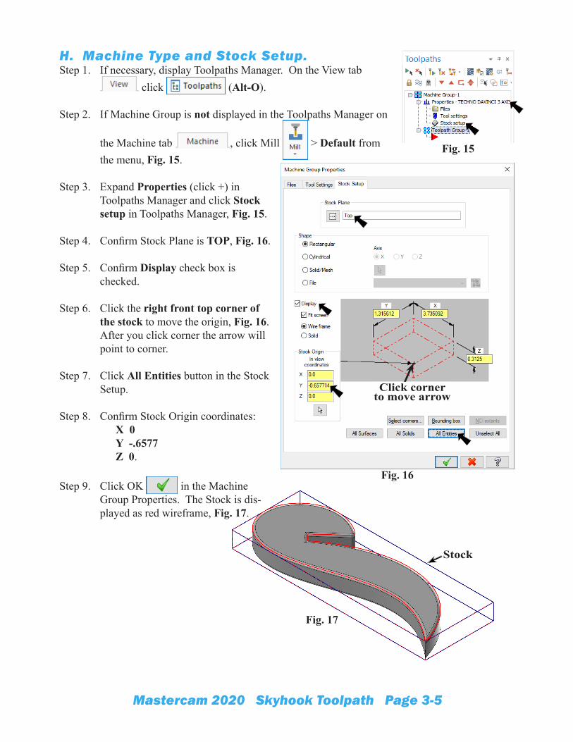
H. Machine Type and Stock Setup.Step 1. If necessary, display Toolpaths Manager. On the View tab
click (Alt-O).
Step 2. If Machine Group is not displayed in the Toolpaths Manager on
the Machine tab , click Mill > Default from the menu, Fig. 15.
Step 3. Expand Properties (click +) in Toolpaths Manager and click Stock setup in Toolpaths Manager, Fig. 15.
Step 4. Confirm Stock Plane is TOP, Fig. 16.
Step 5. Confirm Display check box is checked.
Step 6. Click the right front top corner of the stock to move the origin, Fig. 16. After you click corner the arrow will point to corner.
Step 7. Click All Entities button in the Stock Setup.
Step 8. Confirm Stock Origin coordinates: X 0 Y -.6577 Z 0.
Step 9. Click OK in the Machine Group Properties. The Stock is dis-played as red wireframe, Fig. 17.
Fig. 15
Fig. 16
Click corner to move arrow
Fig. 17
Stock
Mastercam 2020 Skyhook Toolpath Page 3-6
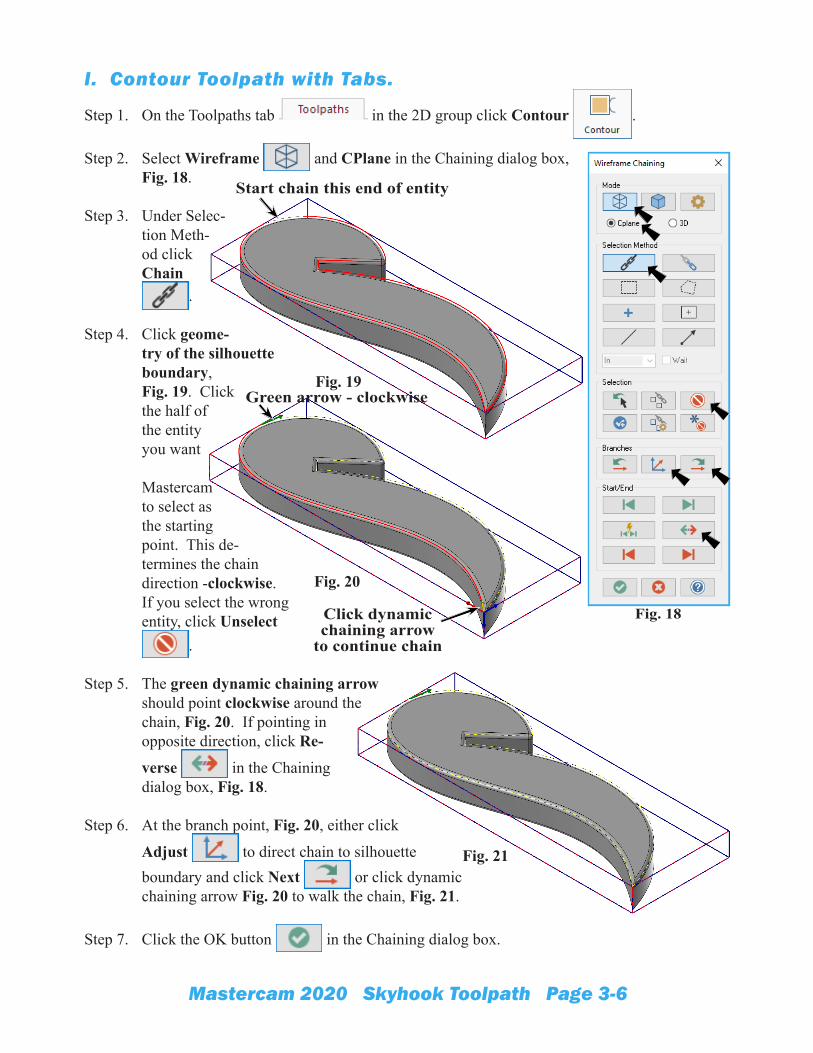
I. Contour Toolpath with Tabs.
Step 1. On the Toolpaths tab in the 2D group click Contour .
Step 2. Select Wireframe and CPlane in the Chaining dialog box, Fig. 18.
Step 3. Under Selec-tion Meth-od click Chain
.
Step 4. Click geome-try of the silhouette boundary,Fig. 19. Click the half of the entity you want
Mastercam to select as the starting point. This de-termines the chain direction -clockwise. If you select the wrong entity, click Unselect
.
Step 5. The green dynamic chaining arrow should point clockwise around the chain, Fig. 20. If pointing in opposite direction, click Re-
verse in the Chaining dialog box, Fig. 18.
Step 6. At the branch point, Fig. 20, either click
Adjust to direct chain to silhouette boundary and click Next or click dynamic chaining arrow Fig. 20 to walk the chain, Fig. 21.
Step 7. Click the OK button in the Chaining dialog box.
Fig. 19
Fig. 18
Fig. 20
Fig. 21
Click dynamic chaining arrow
to continue chain
Start chain this end of entity
Green arrow - clockwise
Mastercam 2020 Skyhook Toolpath Page 3-7
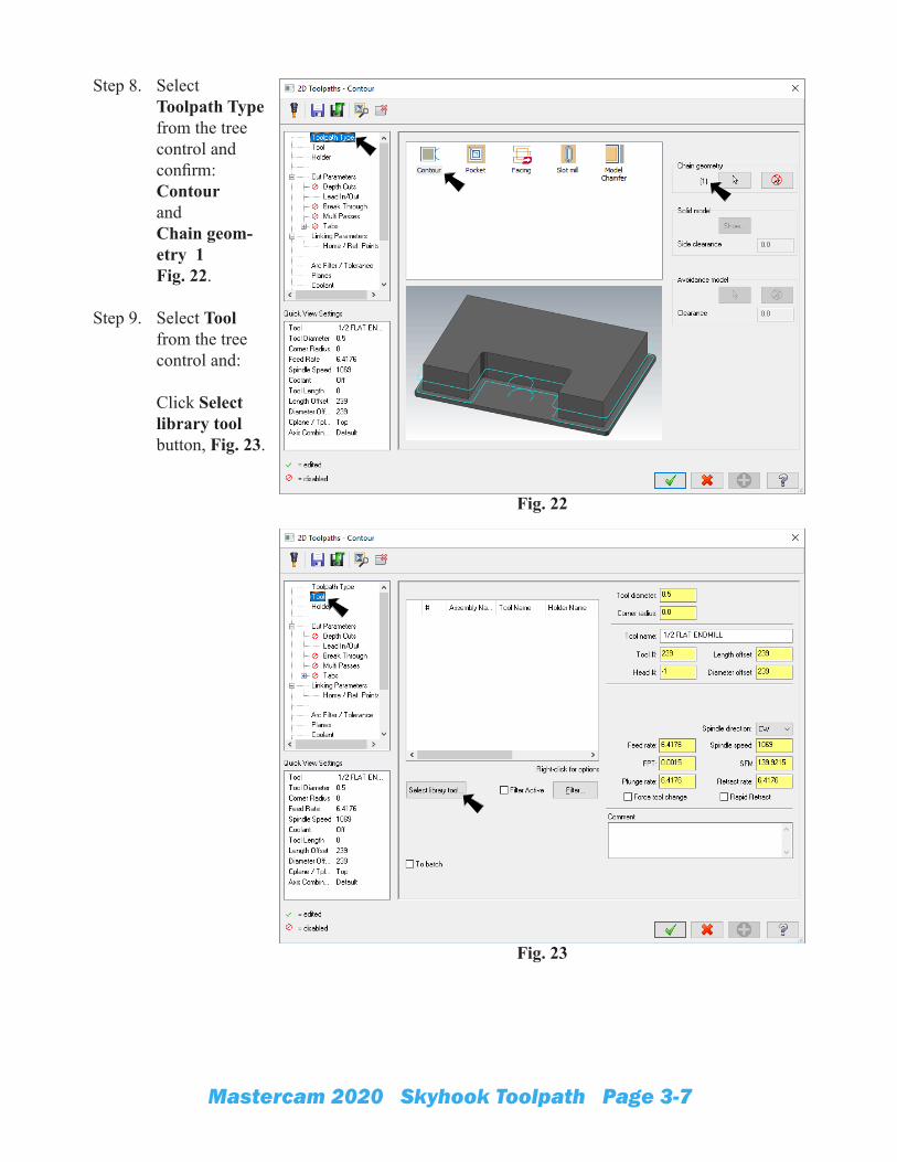
Step 8. Select Toolpath Type from the tree control and confirm: Contour andChain geom-etry 1 Fig. 22.
Step 9. Select Tool from the tree control and: Click Select library tool button, Fig. 23.
Fig. 22
Fig. 23
Mastercam 2020 Skyhook Toolpath Page 3-8
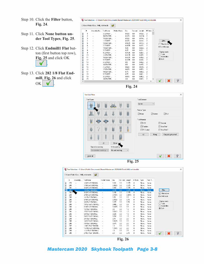
Step 10. Click the Filter button, Fig. 24.
Step 11. Click None button un-der Tool Types, Fig. 25.
Step 12. Click Endmill1 Flat but-ton (first button top row), Fig. 25 and click OK
.
Step 13. Click 282 1/8 Flat End-mill, Fig. 26 and click OK .
Fig. 24
Fig. 25
Fig. 26
Mastercam 2020 Skyhook Toolpath Page 3-9
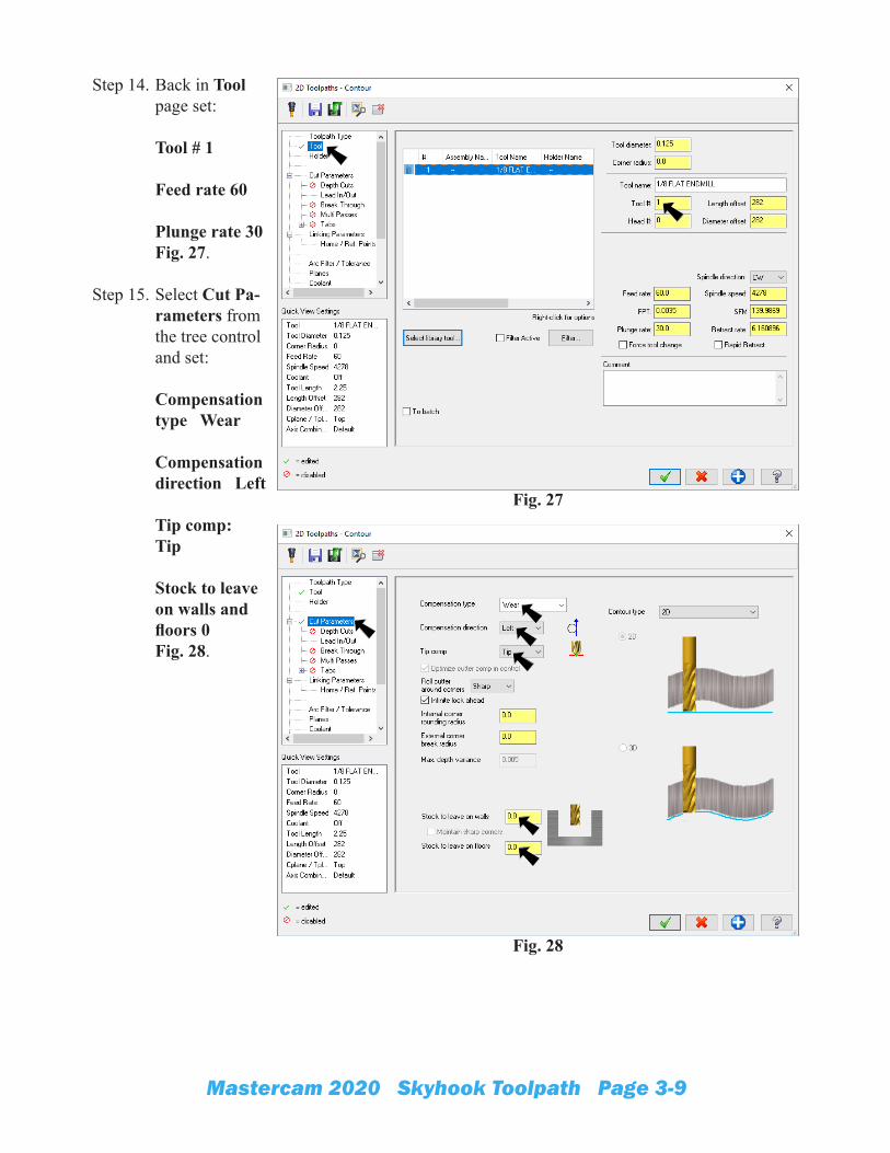
Step 14. Back in Tool page set: Tool # 1 Feed rate 60
Plunge rate 30Fig. 27.
Step 15. Select Cut Pa-rameters from the tree control and set: Compensation type Wear Compensation direction Left Tip comp: Tip Stock to leave on walls and floors 0 Fig. 28.
Fig. 27
Fig. 28
Mastercam 2020 Skyhook Toolpath Page 3-10
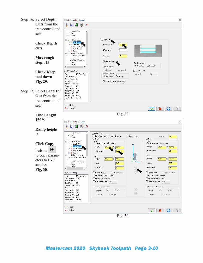
Step 16. Select Depth Cuts from the tree control and set: Check Depth cuts
Max rough step: .15 Check Keep tool down Fig. 29.
Step 17. Select Lead In/Out from the tree control and set:
Line Length 150% Ramp height .2 Click Copy
button to copy param-eters to Exit sectionFig. 30.
Fig. 29
Fig. 30
Mastercam 2020 Skyhook Toolpath Page 3-11
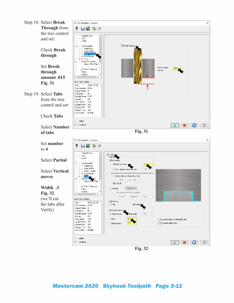
Step 18. Select Break Through from the tree control and set: Check Break through
Set Break through amount .015 Fig. 31.
Step 19. Select Tabs from the tree control and set:
Check Tabs Select Number of tabs Set number to 4 Select Partial Select Vertical moves Width .3 Fig. 32.(we’ll cut the tabs after Verify)
Fig. 31
Fig. 32
Mastercam 2020 Skyhook Toolpath Page 3-12
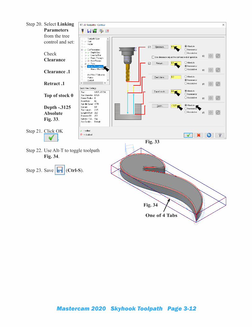
Step 20. Select Linking Parameters from the tree control and set: Check Clearance Clearance .1 Retract .1 Top of stock 0 Depth -.3125 Absolute Fig. 33.
Step 21. Click OK .
Step 22. Use Alt-T to toggle toolpath Fig. 34.
Step 23. Save (Ctrl-S).
Fig. 33
Fig. 34
One of 4 Tabs
Mastercam 2020 Skyhook Toolpath Page 3-13
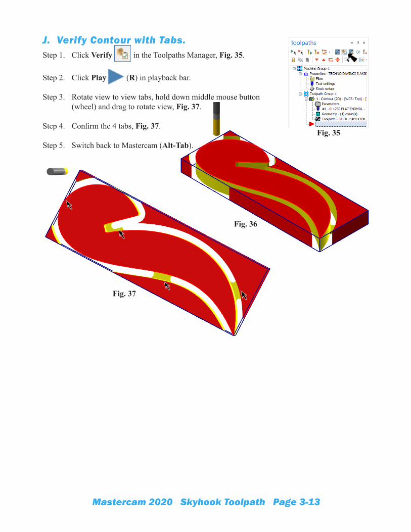
J. Verify Contour with Tabs.Step 1. Click Verify in the Toolpaths Manager, Fig. 35.
Step 2. Click Play (R) in playback bar.
Step 3. Rotate view to view tabs, hold down middle mouse button (wheel) and drag to rotate view, Fig. 37.
Step 4. Confirm the 4 tabs, Fig. 37.
Step 5. Switch back to Mastercam (Alt-Tab).Fig. 35
Fig. 36
Fig. 37
Mastercam 2020 Skyhook Toolpath Page 3-14
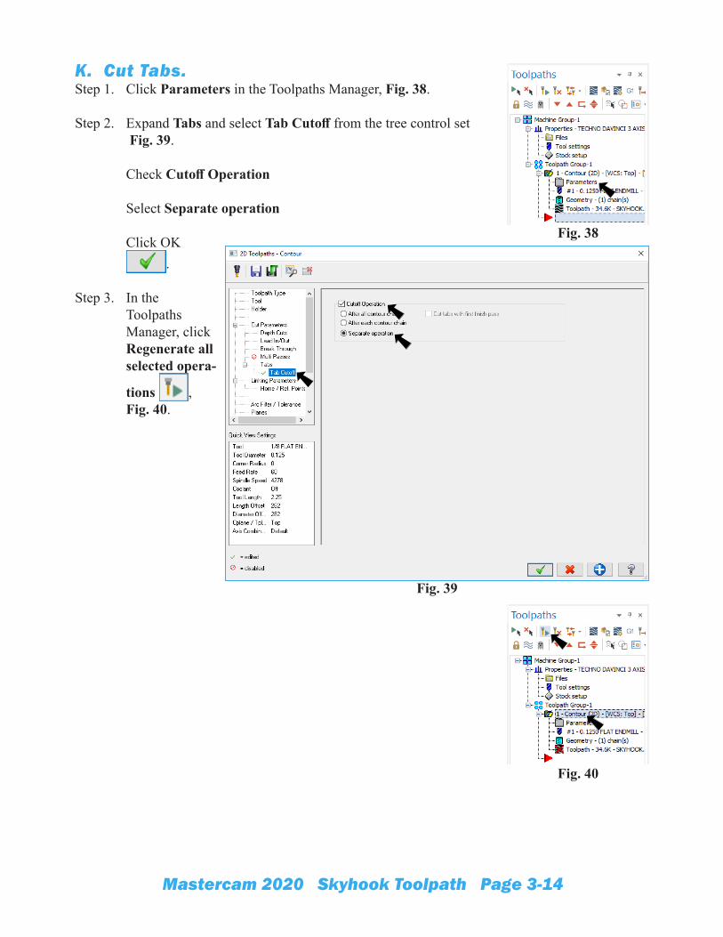
K. Cut Tabs.Step 1. Click Parameters in the Toolpaths Manager, Fig. 38.
Step 2. Expand Tabs and select Tab Cutoff from the tree control set Fig. 39. Check Cutoff Operation Select Separate operation Click OK
.
Step 3. In the Toolpaths Manager, click Regenerate all selected opera-
tions ,Fig. 40.
Fig. 38
Fig. 39
Fig. 40
Mastercam 2020 Skyhook Toolpath Page 3-15
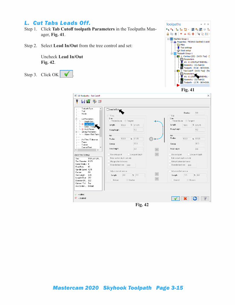
L. Cut Tabs Leads Off.Step 1. Click Tab Cutoff toolpath Parameters in the Toolpaths Man-
ager, Fig. 41.
Step 2. Select Lead In/Out from the tree control and set:
Uncheck Lead In/OutFig. 42.
Step 3. Click OK .
Fig. 42
Fig. 41
Mastercam 2020 Skyhook Toolpath Page 3-16
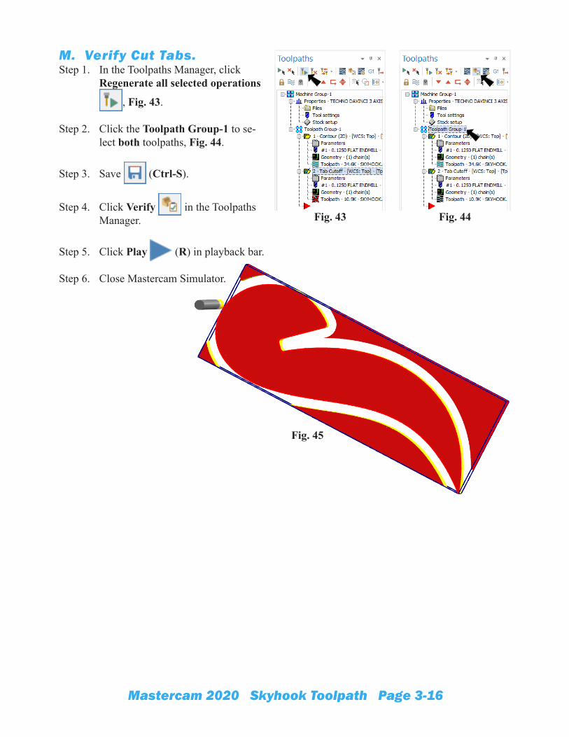
M. Verify Cut Tabs.Step 1. In the Toolpaths Manager, click
Regenerate all selected operations
, Fig. 43.
Step 2. Click the Toolpath Group-1 to se-lect both toolpaths, Fig. 44.
Step 3. Save (Ctrl-S).
Step 4. Click Verify in the Toolpaths Manager.
Step 5. Click Play (R) in playback bar.
Step 6. Close Mastercam Simulator.
Fig. 44Fig. 43
Fig. 45