Embed Size (px)
Citation preview

Department of Applied Information Technology
Master thesis in software engineering and management
A Rationale Focused Software Architecture Documentation method (RFSAD)
Muhammad Asad JavedGöteborg, Sweden 2007
2
REPORT NO. 2007: 115
A RATIONALE FOCUSED SOFTWARE
ARCHITECTURE DOCUMENTATION METHOD
(RFSAD)
Muhammad Asad Javed
Department of Applied Information Technology IT UNIVERSITY OF GÖTEBORG
GÖTEBORG UNIVERSITY AND CHALMERS UNIVERSITY OF TECHNOLOGYGöteborg, Sweden 2007
3
A Rationale Focused Software Architecture Documentation Method (RFSAD)
Muhammad Asad Javed
© Muhammad Asad Javed, 2007
Report no 2007: 115
ISSN: 1651-4769
Department of Applied Information Technology
IT University of Göteborg
Göteborg University and Chalmers University of Technology
P O Box 8718
SE – 402 75 Göteborg
Sweden
Telephone + 46 (0)31-772 4895
Göteborg, Sweden 2007
4
Acknowledgements
Wow! Four months of hard work and I can't believe it's finally finished! All those persons who contributed in my work during that period I would like to thank them all. First and foremost I would like to thank my supervisor Thomas Lundqvist. You are a great supporter and advisor. Furthermore I would like to thank Dr. Muhammad Ali Babar, the advice and support from him has been immeasurable.
I would like to thank all my friends and class mates who helped me a lot during my thesis. I would like to thank Naveed for providing me a lot of help regarding MS Word and also for formatting this report. I would like to thank my friend Rehan who helped me in reviewing English language.
Beyond friends there is family. Thanks for your love and support for no matter what I decided to do and also for the financial support.
Muhammad Asad JavedM.Sc Student
I.T University of Göteborg, SwedenE-Mail: [email protected]
5
A Rationale Focused Software Architecture Documentation Method (RFSAD)
Muhammad Asad Javed
Department of Applied Information Technology
IT University of Göteborg
Göteborg University and Chalmers University of Technology
Abstract
Software architecture plays a vital role in software development, and so does software architecture documentation. Practitioners have been documenting architectures for many years, but researchers have started pointing out problems in software architecture documentation, which in their point of view are hindering true benefits of architecture documentation to reach the industry. In this thesis the problems associated with software architecture documentation are described, and a new method to document software architecture (Rationale Focused Software Architecture Documentation (RFSAD)) is proposed to address those mentioned problems.
Keywords: Software architecture documentation; design rationale; IEEE 1471; Views and Beyond; 4+1 view; architectural views.
6
Table of Contents1. INTRODUCTION................................................................................................................................8
1.1 PROBLEM FORMULATION ..............................................................................................................81.1.1 Aim...........................................................................................................................................9
1.2 IMPORTANCE OF THE RESEARCH QUESTION ...................................................................................91.3 REPORT OUTLINE.........................................................................................................................10
2. METHODOLOGY ............................................................................................................................11
2.1 RESEARCH APPROACH .................................................................................................................12
3. THEORY ............................................................................................................................................13
3.1 SOFTWARE ARCHITECTURE DOCUMENTATION METHODS ...........................................................133.1.1 The IEEE 1471 standard .......................................................................................................133.1.2 SEI’s View and Beyond (V&B) ..............................................................................................16
3.1.2.1 Produce a view list ..................................................................................................................... 173.1.2.2 Documenting views.................................................................................................................... 183.1.2.3 The “B” in V&B ........................................................................................................................ 19
3.1.3 4+1 view ................................................................................................................................193.2 PROBLEMS WITH EXISTING SAD METHODS .................................................................................20
3.2.1 Dynamic and static taxonomies of SAD methods...................................................................203.2.2 Design rationale and SAD methods.......................................................................................213.2.3 Is architecture and design the same thing? ...........................................................................223.2.4 Traceability between requirements and design decisions......................................................223.2.5 Problems related to UML and concerning stakeholders needs .............................................233.2.6 A lot of SAD methods!............................................................................................................23
3.3 OTHER FACTORS AFFECTING SAD...............................................................................................233.3.1 Difference between architecture and detailed design............................................................233.3.2 Different ambiguities are still present in definition of SA......................................................24
3.3.2.1 Criteria for a new method .......................................................................................................... 24
4. A RATIONALE FOCUSED SOFTWARE ARCHITECTURE DOCUMENTATION METHOD (RFSAD) .......................................................................................................................................................26
4.1 STEP 1: DOCUMENTING FUNCTIONAL REQUIREMENTS AND DECISIONS........................................264.2 STEP 2: DOCUMENTING EMERGENT QUALITIES............................................................................264.3 STEP 3: DOCUMENTING SYSTEM LEVEL NON FUNCTIONAL REQUIREMENTS AND DECISIONS........274.4 STEP 4: DRAWING THE COMPLETE SYSTEM..................................................................................284.5 OPTIONAL MATERIAL ..................................................................................................................28
5. EVALUATION ..................................................................................................................................29
5.1 COMPARISON WITH ESTABLISHED METHODS AND STANDARDS....................................................295.1.1 Degree of presence of design rationale .................................................................................295.1.2 Traceability between requirements and corresponding design decisions..............................305.1.3 Degree of addressing the needs of non-technical stakeholders .............................................305.1.4 Description of reasons of neglecting or preference of potential design choices ...................315.1.5 Degree of dynamism ..............................................................................................................315.1.6 Degree of guidance and available examples of implementation............................................325.1.7 Degree of support in terms of documenting iterations of design decisions ...........................325.1.8 Summary of evaluation ..........................................................................................................33
5.2 COMPARISON WITH NEW SAD METHODS.....................................................................................34
6. RELATED WORK ............................................................................................................................36
6.1 DESIGN RATIONALE.....................................................................................................................366.1.1 Significance of DR in the views of researchers......................................................................366.1.2 Tools to capture and use of DR .............................................................................................37
7
6.1.2.1 gIBIS.......................................................................................................................................... 386.1.2.2 QOC........................................................................................................................................... 386.1.2.3 DRL ........................................................................................................................................... 396.1.2.4 SeuRAT ..................................................................................................................................... 396.1.2.5 Architecture Decision Description Template (ADDT)............................................................... 396.1.2.6 SYSIPHUS................................................................................................................................. 39
7. DISCUSSION .....................................................................................................................................41
7.1 STRONG POINTS OF THE RFSAD METHOD...................................................................................417.2 LIMITATIONS...............................................................................................................................42
7.2.1 Limitations of RFSAD method ...............................................................................................427.2.2 Limitations of work ................................................................................................................43
7.3 FUTURE OF SAD METHODS AND STANDARDS..............................................................................437.3.1 DR trend in SAD methods......................................................................................................437.3.2 Reflections on the new version of the IEEE 1471 SAD standard...........................................43
8. CONCLUSION ..................................................................................................................................46
REFERENCES ............................................................................................................................................47
8
1. IntroductionSoftware architecture (SA) as a concept was presented the first time in 1968 by Edsger Dijkstra and later by David Parnas in 1970. They stressed that the overall structure of a software system has its importance and the wrong structure can lead to the wrong system [1]. In 1990 the research on software architecture was increased, and mainly focused on architectural styles, architecture documentation (AD), architecture description languages and formal methods [2].
The concept of Components and connectors was introduced in 1996 by Mary shaw and David Garlan of Carnegie Mellon university. The first formal standard in the area of software architecture documentation (SAD) is ANSI/IEEE 1471-2000 which has also recently been adopted by ISO as ISO/IEC DIS 42010 [3].
From the above introduction it is clear that the software architecture documentation is a new field. Although professionals have been documenting their proposed software architecture for many years, but as mentioned above the first ever formal effort made to develop a standard for software architecture documentation was done in year 2000 [3].
Many informal approaches are used to document software architecture, including boxes and lines and simple class diagrams [4], and at least half a dozen formal methods exist for software architecture documentation [5]. Because of being a relatively new field in software development, software architecture documentation is facing different kinds of problems. These problems include linking requirements to design decisions, documenting and managing design decisions and other problems or limitations in existing SAD methods. One of the major problems identified by researchers [8], [9], [26], [28], [15], [29] in SAD is the explicit representation of design rationales.
This thesis conducts a literature study and identifies problems associated with SAD. It also proposes a new method to document SA, the Rationale Focused Software Architecture Documentation (RFSAD) method, as a solution to eradicate identified problems. Furthermore, this thesis discusses efforts made so far to capture and manage design rationales (DR) and analyzes different DR tools.
1.1 Problem formulationThis section presents a summary of problems associated with software architecture documentation which motivated the author to conduct this study. Software architecture documentation suffers from a number of fundamental problems. Those problems range from the definition of software architecture to problems caused by the existence of multiple SAD methods. There are different definitions available of software architecture e.g. [25], [53], [8].
Problems like lack of description of design rationales, lack of traceability between requirements and corresponding design decisions, and their consequent effect to both product and process are topics really needed to be focused on today. From the above discussion it is clear that there is a strong need to emphasize on software architecture
9
documentation to solve above mentioned problems. The Question “How to improve Software Architecture documentation?” is the research question of this master thesis.
1.1.1 AimThe aim of this research is to analyze weaknesses of different SAD methods and to propose a new method for documenting software architecture.
1.2 Importance of the research questionPer Sundblad [18] describes that, according to studies performed by companies such as the Gartner Group, the Standish Group, and IDC, a majority of software development projects failed to produce anything useful at all and also failed to support and satisfy business needs. The author later describes that the main reason behind that failure was the fact that software architects could not understand and transform business requirements into reliable software architecture.
Lex Bijlsma [19] defines software architecture as defining the global structure of a system, its components and the relationship between those components. If software architects design the wrong system, the maintenance cost would be very high. Different stakeholders have different requirements which are often contradictory [19]. This also depicts the importance of the role of a software architect, as s/he has to deal with different kinds of requirements and have to design an optimized solution to meet the needs of all concerned stakeholders.
Software architecture definitions page [20] at SEI’s website describes it as: “Software architecture forms the backbone for any successful software-intensive system. Architecture is the primary carrier of a software system's quality attributes such as performance or reliability. The right architecture - correctly designed to meet its quality attribute requirements, clearly documented, and conscientiously evaluated - is the linchpin for software project success. The wrong one is a recipe for guaranteed disaster. “[20]
This describes the importance of the software architecture phase in the software development life cycle. A lot of efforts have been made to develop methodologies to capture and design user requirements in an efficient way, but less concentration has been spent on how to document that proposed design. And a good software architectural design would be useless if it would not be able to convey itself to stakeholders. When software architecture documentation is related to software architecture itself, it can be concluded easily that to describe and present a proposed architectural design, a good documentation is needed, which proves the equal importance of SA documentation along with SA.
10
1.3 Report outlineChapter 2 discusses the research methodology. Chapter 3 discusses different software architecture documentation methods as well as problems identified in them. Chapter 4presents the new SAD method, the Rational Focused Software Architecture Documentation (RFSAD) method, while Chapter 5 presents the evaluation of RFSAD in comparison with other SAD methods. Chapter 6 discusses different design rationale capturing techniques and tools. Chapter 7 discusses strong and weak points of the RFSAD method as well as presents reflections on the future of SAD methods. Chapter 8presents a summary of the overall work.
11
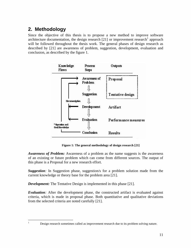
2. MethodologySince the objective of this thesis is to propose a new method to improve software architecture documentation, the design research [21] or improvement research1 approach will be followed throughout the thesis work. The general phases of design research as described by [21] are awareness of problem, suggestion, development, evaluation and conclusion, as described by the figure 1.
Figure 1: The general methodology of design research [21]
Awareness of Problem: Awareness of a problem as the name suggests is the awareness of an existing or future problem which can come from different sources. The output of this phase is a Proposal for a new research effort.
Suggestion: In Suggestion phase, suggestion/s for a problem solution made from the current knowledge or theory base for the problem area [21].
Development: The Tentative Design is implemented in this phase [21].
Evaluation: After the development phase, the constructed artifact is evaluated against criteria, which is made in proposal phase. Both quantitative and qualitative deviations from the selected criteria are noted carefully [21].
1 Design research sometimes called as improvement research due to its problem solving nature.
12
Conclusion: This phase is considered as the finale of all the research effort made. The consolidated results and knowledge gained in the effort is summarized here along with any deficiency in the research, which could become basis for further research [21].
2.1 Research approachDesign research approach is used in order to carry out research. After the proposal phase a thorough literature study was conducted. The literature study surrounded software architecture documentation standards, problems in software architecture documentation, problems related to software architecture documentation standards, reviews of professionals about software architecture, its standards, and problems and future. IEEE explore, ACM library and Chalmers digital library were used as main sources of knowledge.
In the development phase the tentative method was given a shape. In the beginning it was aimed that the new method would be implemented by a using real time system requirements as well as Krutchen’s 4+1 view method and IEEE 1471 standard followed by a comparative analysis of that implementation, but due to short span of time it was decided to exclude this from the scope and would be done in future.
In order to compare the new method with other available methods, in evaluation phase the new method is discussed in comparison with Krutchen’s 4+1 view and IEEE 1471 standard. The basis of that comparison is a criteria, which is developed from the existing problems associated with SAD mentioned by researchers, as described in” problems with existing SAD methods” section. That evaluation is not a thorough one because of lack of resources. A detailed comparative study is needed in order to prove the effectiveness of the new method.
13
3. TheoryThis chapter presents different software architecture documentation methods and identifies problems associated with them. In subsection 3.1, different software architecture documentation methods are described. Subsection 3.2 describes different problems associated with various SAD methods. Subsection 3.3 describes the criteria for a new method to document software architecture.
3.1 Software Architecture Documentation methodsIn this section different SAD standards are described in order to show the sequence of steps in order to document software system’s architecture.
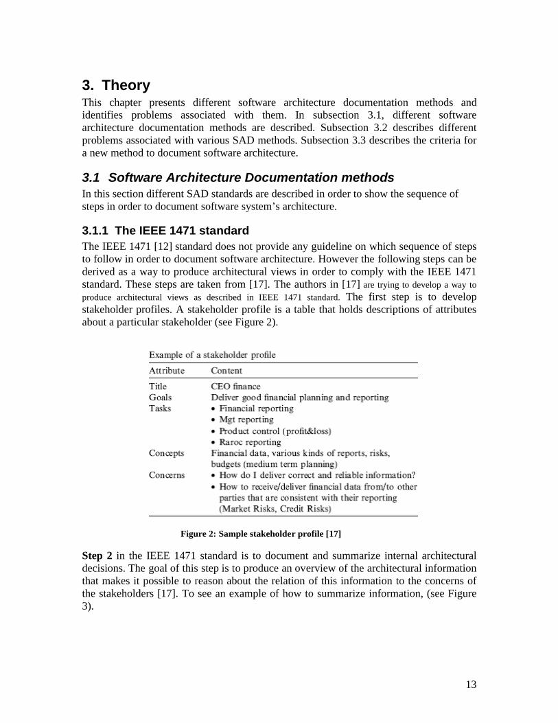
3.1.1 The IEEE 1471 standardThe IEEE 1471 [12] standard does not provide any guideline on which sequence of steps to follow in order to document software architecture. However the following steps can be derived as a way to produce architectural views in order to comply with the IEEE 1471 standard. These steps are taken from [17]. The authors in [17] are trying to develop a way to
produce architectural views as described in IEEE 1471 standard. The first step is to develop stakeholder profiles. A stakeholder profile is a table that holds descriptions of attributes about a particular stakeholder (see Figure 2).
Figure 2: Sample stakeholder profile [17]
Step 2 in the IEEE 1471 standard is to document and summarize internal architectural decisions. The goal of this step is to produce an overview of the architectural information that makes it possible to reason about the relation of this information to the concerns of the stakeholders [17]. To see an example of how to summarize information, (see Figure 3).
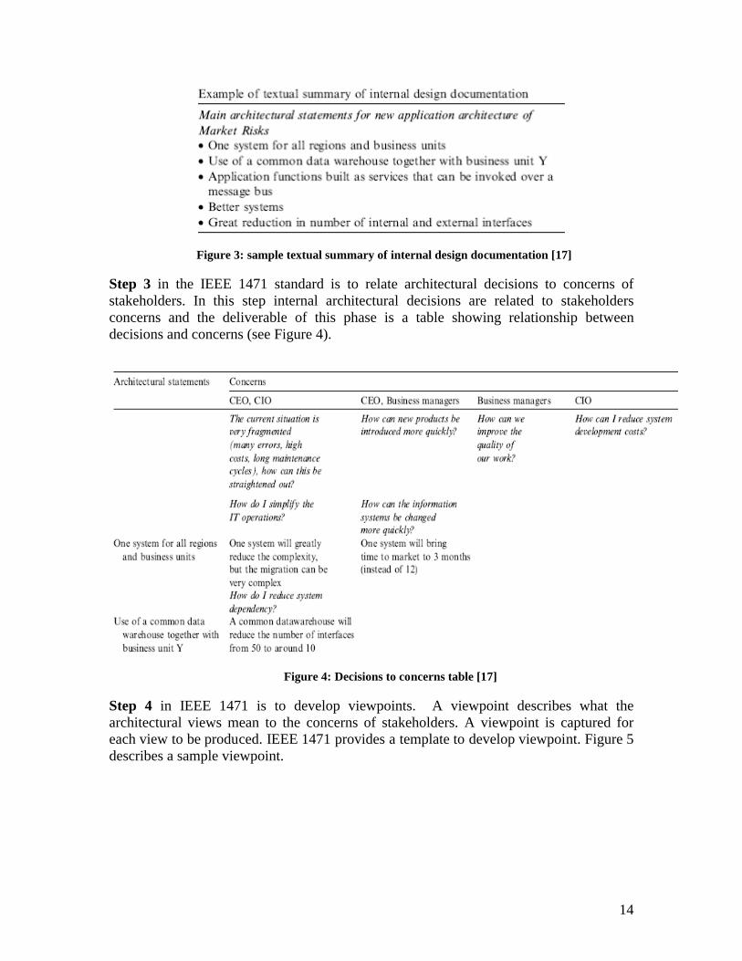
14
Figure 3: sample textual summary of internal design documentation [17]
Step 3 in the IEEE 1471 standard is to relate architectural decisions to concerns of stakeholders. In this step internal architectural decisions are related to stakeholders concerns and the deliverable of this phase is a table showing relationship between decisions and concerns (see Figure 4).
Figure 4: Decisions to concerns table [17]
Step 4 in IEEE 1471 is to develop viewpoints. A viewpoint describes what the architectural views mean to the concerns of stakeholders. A viewpoint is captured for each view to be produced. IEEE 1471 provides a template to develop viewpoint. Figure 5describes a sample viewpoint.
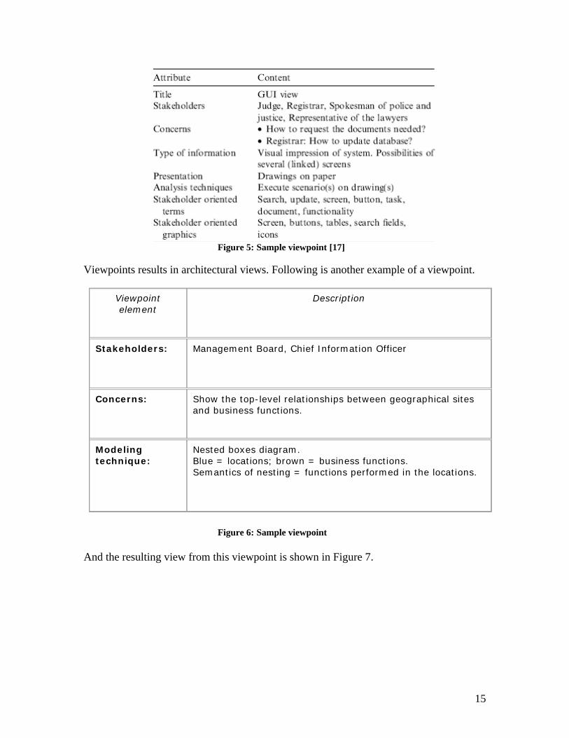
15
Figure 5: Sample viewpoint [17]
Viewpoints results in architectural views. Following is another example of a viewpoint.
Figure 6: Sample viewpoint
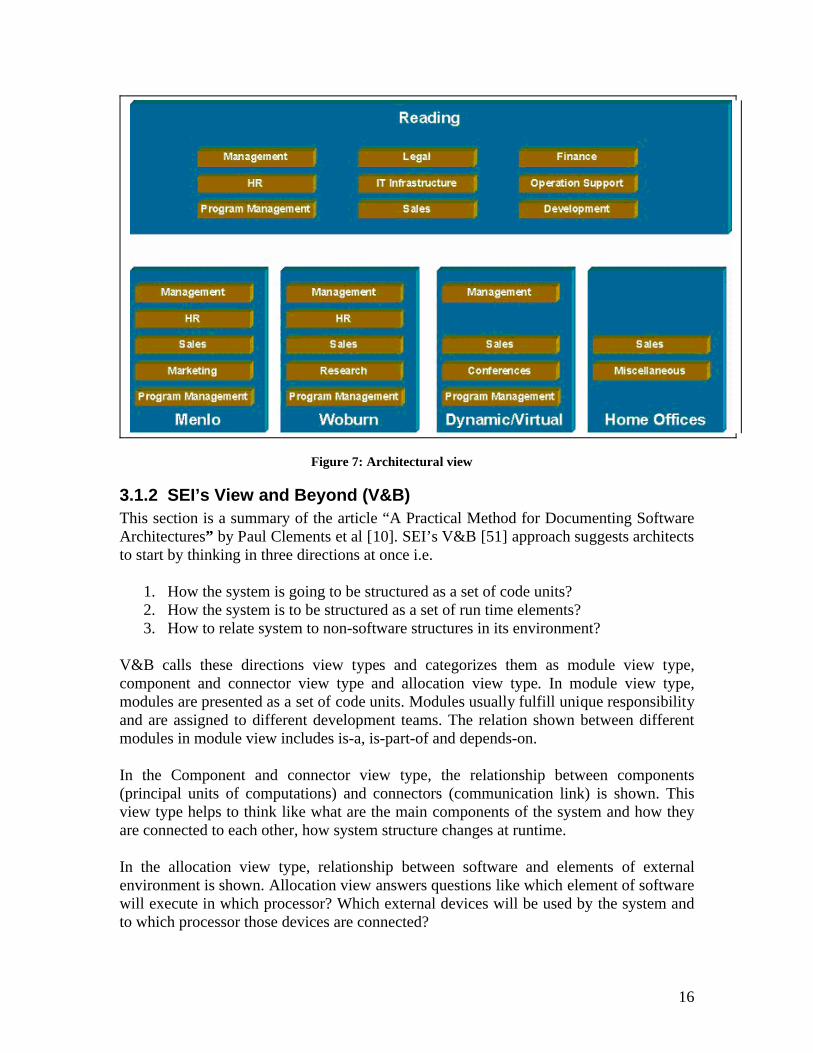
And the resulting view from this viewpoint is shown in Figure 7.
Viewpoint element
Description
Stakeholders: Management Board, Chief Information Officer
Concerns: Show the top-level relationships between geographical sites and business functions.
Modeling technique:
Nested boxes diagram. Blue = locations; brown = business functions.Semantics of nesting = functions performed in the locations.
16
Figure 7: Architectural view
3.1.2 SEI’s View and Beyond (V&B)This section is a summary of the article “A Practical Method for Documenting Software Architectures” by Paul Clements et al [10]. SEI’s V&B [51] approach suggests architects to start by thinking in three directions at once i.e.
1. How the system is going to be structured as a set of code units?2. How the system is to be structured as a set of run time elements?3. How to relate system to non-software structures in its environment?
V&B calls these directions view types and categorizes them as module view type, component and connector view type and allocation view type. In module view type, modules are presented as a set of code units. Modules usually fulfill unique responsibility and are assigned to different development teams. The relation shown between different modules in module view includes is-a, is-part-of and depends-on.
In the Component and connector view type, the relationship between components (principal units of computations) and connectors (communication link) is shown. This view type helps to think like what are the main components of the system and how they are connected to each other, how system structure changes at runtime.
In the allocation view type, relationship between software and elements of external environment is shown. Allocation view answers questions like which element of software will execute in which processor? Which external devices will be used by the system and to which processor those devices are connected?
17
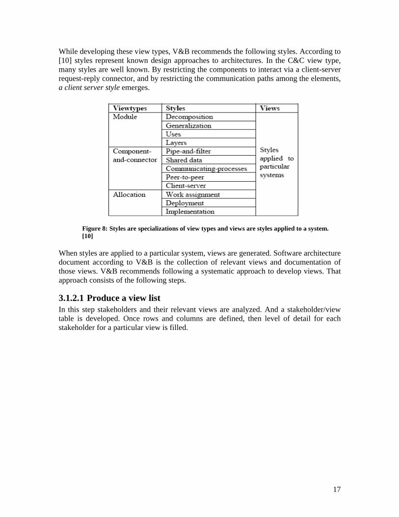
While developing these view types, V&B recommends the following styles. According to [10] styles represent known design approaches to architectures. In the C&C view type, many styles are well known. By restricting the components to interact via a client-server request-reply connector, and by restricting the communication paths among the elements, a client server style emerges.
Figure 8: Styles are specializations of view types and views are styles applied to a system. [10]
When styles are applied to a particular system, views are generated. Software architecture document according to V&B is the collection of relevant views and documentation of those views. V&B recommends following a systematic approach to develop views. That approach consists of the following steps.
3.1.2.1 Produce a view listIn this step stakeholders and their relevant views are analyzed. And a stakeholder/view table is developed. Once rows and columns are defined, then level of detail for each stakeholder for a particular view is filled.
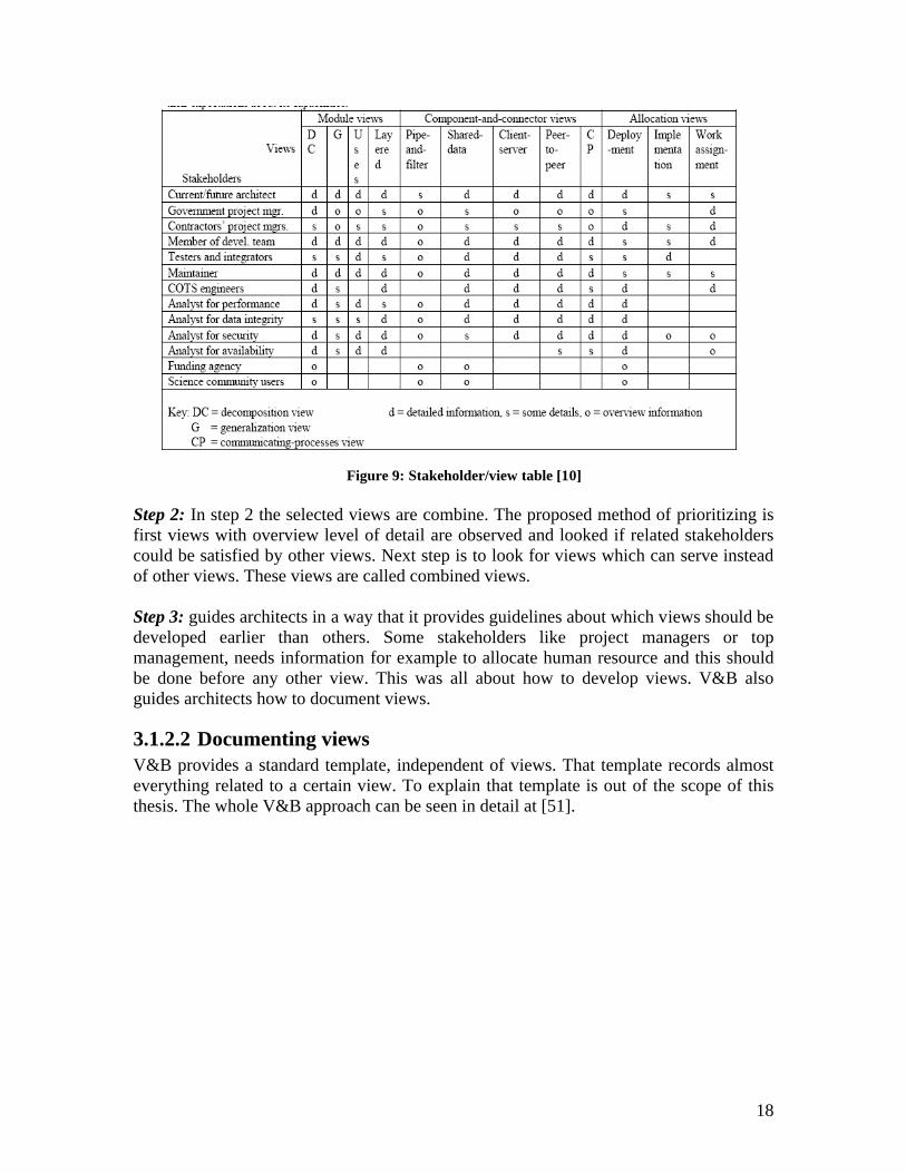
18
Figure 9: Stakeholder/view table [10]
Step 2: In step 2 the selected views are combine. The proposed method of prioritizing is first views with overview level of detail are observed and looked if related stakeholders could be satisfied by other views. Next step is to look for views which can serve instead of other views. These views are called combined views.
Step 3: guides architects in a way that it provides guidelines about which views should be developed earlier than others. Some stakeholders like project managers or top management, needs information for example to allocate human resource and this should be done before any other view. This was all about how to develop views. V&B also guides architects how to document views.
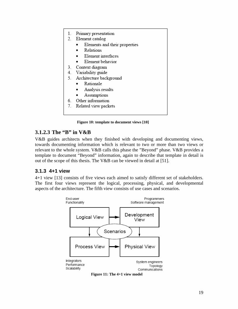
3.1.2.2 Documenting viewsV&B provides a standard template, independent of views. That template records almost everything related to a certain view. To explain that template is out of the scope of this thesis. The whole V&B approach can be seen in detail at [51].
19
Figure 10: template to document views [10]
3.1.2.3 The “B” in V&BV&B guides architects when they finished with developing and documenting views, towards documenting information which is relevant to two or more than two views or relevant to the whole system. V&B calls this phase the ”Beyond” phase. V&B provides a template to document “Beyond” information, again to describe that template in detail is out of the scope of this thesis. The V&B can be viewed in detail at [51].
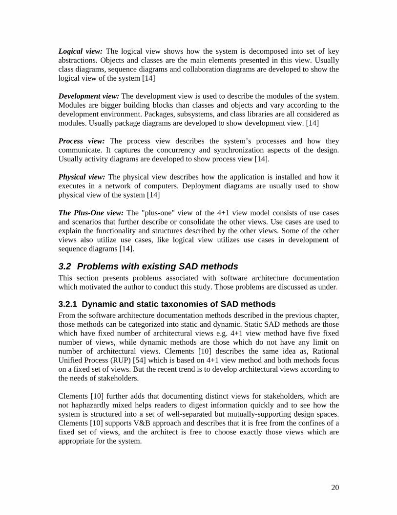
3.1.3 4+1 view4+1 view [13] consists of five views each aimed to satisfy different set of stakeholders.The first four views represent the logical, processing, physical, and developmental aspects of the architecture. The fifth view consists of use cases and scenarios.
Figure 11: The 4+1 view model
20
Logical view: The logical view shows how the system is decomposed into set of key abstractions. Objects and classes are the main elements presented in this view. Usually class diagrams, sequence diagrams and collaboration diagrams are developed to show the logical view of the system [14]
Development view: The development view is used to describe the modules of the system. Modules are bigger building blocks than classes and objects and vary according to the development environment. Packages, subsystems, and class libraries are all considered as modules. Usually package diagrams are developed to show development view. [14]
Process view: The process view describes the system’s processes and how they communicate. It captures the concurrency and synchronization aspects of the design.Usually activity diagrams are developed to show process view [14].
Physical view: The physical view describes how the application is installed and how it executes in a network of computers. Deployment diagrams are usually used to show physical view of the system [14]
The Plus-One view: The "plus-one" view of the 4+1 view model consists of use cases and scenarios that further describe or consolidate the other views. Use cases are used to explain the functionality and structures described by the other views. Some of the other views also utilize use cases, like logical view utilizes use cases in development of sequence diagrams [14].
3.2 Problems with existing SAD methodsThis section presents problems associated with software architecture documentation which motivated the author to conduct this study. Those problems are discussed as under.
3.2.1 Dynamic and static taxonomies of SAD methodsFrom the software architecture documentation methods described in the previous chapter, those methods can be categorized into static and dynamic. Static SAD methods are those which have fixed number of architectural views e.g. 4+1 view method have five fixed number of views, while dynamic methods are those which do not have any limit on number of architectural views. Clements [10] describes the same idea as, Rational Unified Process (RUP) [54] which is based on 4+1 view method and both methods focus on a fixed set of views. But the recent trend is to develop architectural views according to the needs of stakeholders.
Clements [10] further adds that documenting distinct views for stakeholders, which are not haphazardly mixed helps readers to digest information quickly and to see how the system is structured into a set of well-separated but mutually-supporting design spaces. Clements [10] supports V&B approach and describes that it is free from the confines of a fixed set of views, and the architect is free to choose exactly those views which are appropriate for the system.
21
Paul Clements in [7] states that IEEE 1471 begins with stakeholders and their concerns. These concerns are listed explicitly, and then viewpoints are developed that (together) satisfy the stakeholders and their concerns. Finally, views are developed to describe the architecture. Those views are based on previously developed viewpoints. Thus with the 1471 approach, we have
Stakeholders/concerns TO viewpoints TO Views
Documenting a style as a view is done if the view has an important stakeholder/concern constituency. Thus with the V&B approach, we have
Structures/styles TO chosen to document based on Stakeholder/Concerns TO Views
Thus, both 1471 and V&B will produce an architecture document that consists of a set of views that satisfy the concerns of the architecture’s key stakeholders. However Paul Clements et al. in [10] states that “IEEE 1471 provides a philosophical foundation and a small number of guidelines but does not prescribe how to construct a usable documentation package.”
When the dynamic architectural documentation models like IEEE 1471 or V&B methods are compared with the fixed one like 4+1 view method, the 4+1 view method gives strong rationales on how to categorize views, but it does not give clear guidelines to architects about, how to document individual views. Since the original article by krutchen [13] presents examples in a language other than UML, there is not a clear guidance about which UML diagrams should be developed for which views.
Different people use their perception to develop different diagrams for same view, and same diagrams for different views. For example [14] describes that the logical view can be described by class diagram, sequence diagram or collaboration diagram, and the process view can be described by activity diagram, while [16] describes that the logical view is possible to document by class diagram and object diagram. The author dedicates collaboration and sequence diagrams for process view.
It is stated by krutchen [13] that the standard is flexible and some systems may require additional views, e.g. a data view and a security view, but the standard does not provide guidelines how to relate those views to traditional views.
3.2.2 Design rationale and SAD methodsThe documentation of design rationales as considered in IEEE 1471 and V&B differ from each other. According to [9] both IEEE 1471 and V&B are deficient in several ways. For example, the former provides a definition of design rationale without further elaboration, while the latter provides a list of elements that comprise rationale without justifying why these elements are important and how the information captured is beneficial in different contexts. Moreover, it is not clear what types of specific information should be captured as design rationale. Capilla et. al. [26] also mentioned that although V&B stresses the
22
need of capturing architectural design rationales, but they do not mention how to record them for future use.
The existing approaches not only lack in clearly documenting architecture design rationales, they also provide not enough guidelines on how to capture and maintain the details on which design decisions are based. These approaches also do not provide enough guidelines on how to document different types of design information (such as patterns, styles, tactics and others). Such information represents architecturally significant knowledge, which can be valuable throughout the software development lifecycle. This lack of capturing and maintaining details about design decision can increase involvement of tacit knowledge in software development process [15].
Errors and tacit knowledge in SAD can contribute to ambiguities in later stages of software development process. Jon Bosch [8] indicates few more problems associated with software development process in general and software architecture in particular. He proposes new definition of software architecture and suggests that existing problems of software architecture are caused by knowledge vaporization.
All knowledge associated with domain analysis, architectural and design patterns and design decisions are embedded in software architecture. But there is a lack of first class representation of these design decisions in software architecture document. And due to that the knowledge associated with these design decisions is lost and secondly design rules can easily be violated in case of change in software architecture.
If design rationales are specified in a software architecture document, it is not mentioned that why a certain decision is preferred from its alternative potential choices? There is a clear lack of representation of alternative design choices in software architecture documentation practices [9].
3.2.3 Is architecture and design the same thing? Since software architecture is comparatively new field, it is not explicitly mentioned in usual SDLC (software development life cycle) phases [55] which includes project planning, requirement analysis followed by design, implementation, testing and support. However, generally the design phase of an SDLC is divided into two sub phases i.e. architecture and design. Division of a phase into two sub parts causes confusions in minds of professionals and they start to mix both of them. In those cases in software architecture document, there is more detailed design than architectural design and the essence of both architectural and detailed design is lost. Kazman [6] have also discussed this idea and have described that both architecture and design are used as synonyms, which has created a wasted overlapping and imprecise communication.
3.2.4 Traceability between requirements and design decisionsSoftware architecture has major contribution in fulfilling of non functional requirements and quality goals, but usually before developing architectural artifacts, these requirements are not thoroughly considered and if considered, the design rationales chosen to fulfill those goals are not described. Moreover the connection between requirements and
23
corresponding design decision is not specified, which contributes more tacit knowledge involved in software development process. Capilla [28] have also discussed the need of traceability between requirements and design decisions.
3.2.5 Problems related to UML and concerning stakeholders needsA view in the 4+1 view model consists of UML diagrams and the 4+1 view model itself is a combination of views. According to [10] UML diagrams provide notational approaches but do not help to convey the wealth of supplementary information necessary for someone to understand architecture. So the 4+1 view clearly lacks the necessary information to stakeholders.
The set of stakeholders for software architecture document is wide spread, and among those stakeholders there are project managers, clients and users, which are usually ignored (particularly clients and users). Stakeholders particularly clients and users are not technical enough to understand technical and complex diagrams which are developed usually in UML.
3.2.6 A lot of SAD methods!Different methods have been proposed from different organizations and researchers, to document software architecture and to address the existing problems, this has lead to another problem “the vaporization of strategic decisions” as different standards tend to attack on the same problem from different ways, and if a certain standard will be used, benefits offered by other standards will be ignored.
3.3 Other factors affecting SADApart from the factors mentioned above, there are some other factors which are not directly related to software architecture documentation but are affecting it. Those factors are related to definition of software architecture and defining its role in software development life cycle. It is obvious that in the presence of ambiguities, misconceptions and contradictions related to definition of software architecture itself, the objective of achieving high quality documentation can not be accomplished. In this section those factors are mentioned.
3.3.1 Difference between architecture and detailed designDifferent opinions exist about the question that “is there any difference between software architecture and detailed design?” Some people think that architecture and design are the same, other school of thought says that architecture is at a level of abstraction above design. Kazman in [6] describes “The lack of a clear distinction among “architecture”, “detailed design” is the cause of much muddy thinking, imprecise communication, and wasted, overlapping effort. For example, “architecture” is often used as a mere synonym for “design” (sometimes preceded with the adjective “high-level”). And many people use the term “architectural patterns” as a synonym for “design patterns.””
In practice, both architecture and design terms are used to describe the same concept by research, industry and academia [24]. During writing of thesis report, the author met with experienced developers of some company. All of them had ten or more years experience
24
in software development in industry. When we talked about the difference in architecture and design, All of them explicitly expressed that they were even not had an idea about such a concept. In their views both concepts were the same. During my own personal experience in industry, usual SDLC steps performed were analysis followed by design phase. After the design phase implementation, testing, deployment and support were performed respectively.
The artifacts which were produced during design phase were functional specification document, use case diagrams, sequence/collaboration and class diagrams. The class diagrams were usually detailed and were used to generate code through CASE tools. A database design was also prepared during design phase. The same pattern was followed for most of the applications. For some applications the architectural design was developed and the ‘architecture’ consisted of a big box and lines diagram of whole system printed on plotter and a big data flow diagram of whole system which was also printed on plotter.
Siemens catalog [23] describes software architecture and design patterns at the same level [24]. It is common in student projects that there is usually not a separate architecture document, but it is a part of design document and all the ‘architecture’ consists of a box and line diagram of the whole system. Rick kazman et. al. [24] describes criteria which are known as intension/locality criteria. According to that, software architecture consists of non-local and strategic statements, where as design consists of local, intentional and tactical statements. The authors go one level deeper and define source code as set of local, extensional and implementation statements.
3.3.2 Different ambiguities are still present in definition of SAAlong with the presence of different software architecture documentation standards, there exit strange definitions of software architecture at the same time. E.g. [25] defines software architecture as “The design of application or system software that incorporates protocols and interfaces for interacting with other programs and for future flexibility and expandability. A self-contained, stand-alone program would have program logic, but not software architecture.”
It is strange to see this kind of definition of SA in this age and surprisingly not in old literature but in modern encyclopedia.
3.3.2.1 Criteria for a new method When the above mentioned problems related to SAD are considered, they seem to revolve around some common factors. Those factors include documenting design rationale; satisfying different stakeholders’ concerns including non technical ones, traceability between requirements and architecture are the main factors. Documenting other supplementary information for example, documenting current status of the decision and documenting different architectural patterns used are also important.
There is a strong need to not to limit the number of architectural views and the choice of views should be left to the architects. Stakeholders’ needs in terms of communicating
25
architectural knowledge should be taken care. There is a need to add all these things in the existing SAD methods as well as to increase compatibility between different methods so that they can complement each other. SAD methods should be easy to follow and flexible with substantial amount of practical guidelines and examples should be provided to avoid ambiguities. All the above facts were thought as the requirements while developing the new method.
26
4. A Rationale Focused Software Architecture Documentation method (RFSAD)
The proposed new method consists of four steps. Each step consists of both documenting related information and drawing architectural diagrams.
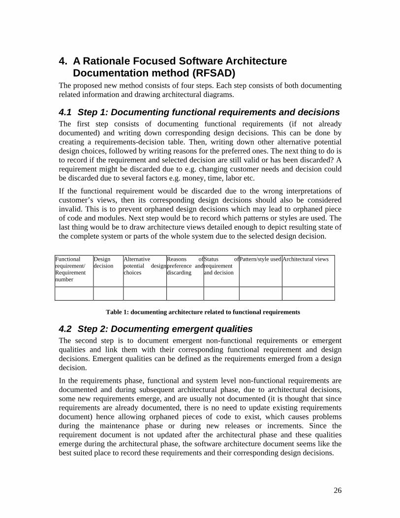
4.1 Step 1: Documenting functional requirements and decisionsThe first step consists of documenting functional requirements (if not already documented) and writing down corresponding design decisions. This can be done by creating a requirements-decision table. Then, writing down other alternative potential design choices, followed by writing reasons for the preferred ones. The next thing to do is to record if the requirement and selected decision are still valid or has been discarded? A requirement might be discarded due to e.g. changing customer needs and decision could be discarded due to several factors e.g. money, time, labor etc.
If the functional requirement would be discarded due to the wrong interpretations of customer’s views, then its corresponding design decisions should also be considered invalid. This is to prevent orphaned design decisions which may lead to orphaned piece of code and modules. Next step would be to record which patterns or styles are used. The last thing would be to draw architecture views detailed enough to depict resulting state of the complete system or parts of the whole system due to the selected design decision.
Functional requirement/ Requirement number
Design decision
Alternative potential design choices
Reasons of preference and discarding
Status of requirement and decision
Pattern/style used Architectural views
Table 1: documenting architecture related to functional requirements
4.2 Step 2: Documenting emergent qualitiesThe second step is to document emergent non-functional requirements or emergent qualities and link them with their corresponding functional requirement and design decisions. Emergent qualities can be defined as the requirements emerged from a design decision.
In the requirements phase, functional and system level non-functional requirements are documented and during subsequent architectural phase, due to architectural decisions, some new requirements emerge, and are usually not documented (it is thought that since requirements are already documented, there is no need to update existing requirements document) hence allowing orphaned pieces of code to exist, which causes problems during the maintenance phase or during new releases or increments. Since the requirement document is not updated after the architectural phase and these qualities emerge during the architectural phase, the software architecture document seems like the best suited place to record these requirements and their corresponding design decisions.
27
Moreover, emergent qualities are often ignored e.g. the security requirements for a university admissions management system could be to prevent unauthorized access by using username and password. But during the architectural phase if it is decided that a certain e-mail server will be used in order to send automated emails to applicants, that decision emerges new associated quality requirements, e.g. security requirements of that particular e-mail server.
And those requirements might not be considered during prior requirements gathering phase. These emergent requirements would be different in case of other e-mail server and the usual security requirements like login/password requirement for the whole application would still exist, independent of the choice of the email server or even not considering the email server at all. It means that emergent properties are separate from the traditional system level non-functional requirements, although they complement them.
The next thing would be to document other alternative potential design decisions and the reasons why selected decision has been given priority from the other ones. the next thing to do is to record that weather the emergent NFR and selected decision is still valid or not. If the primary FR in future would be de-activated or discarded, then the design decision to fulfill that requirement would also be discarded along with the emergent requirement and the corresponding decision would also be considered invalid.
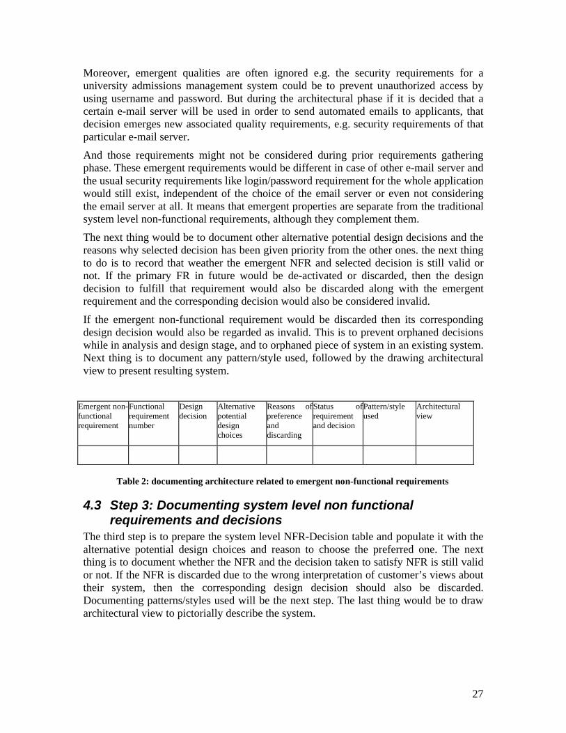
If the emergent non-functional requirement would be discarded then its corresponding design decision would also be regarded as invalid. This is to prevent orphaned decisions while in analysis and design stage, and to orphaned piece of system in an existing system. Next thing is to document any pattern/style used, followed by the drawing architectural view to present resulting system.
Emergent non-functional requirement
Functional requirement number
Design decision
Alternative potential design choices
Reasons of preference and discarding
Status of requirement and decision
Pattern/style used
Architectural view
Table 2: documenting architecture related to emergent non-functional requirements
4.3 Step 3: Documenting system level non functional requirements and decisions
The third step is to prepare the system level NFR-Decision table and populate it with the alternative potential design choices and reason to choose the preferred one. The next thing is to document whether the NFR and the decision taken to satisfy NFR is still valid or not. If the NFR is discarded due to the wrong interpretation of customer’s views about their system, then the corresponding design decision should also be discarded. Documenting patterns/styles used will be the next step. The last thing would be to draw architectural view to pictorially describe the system.
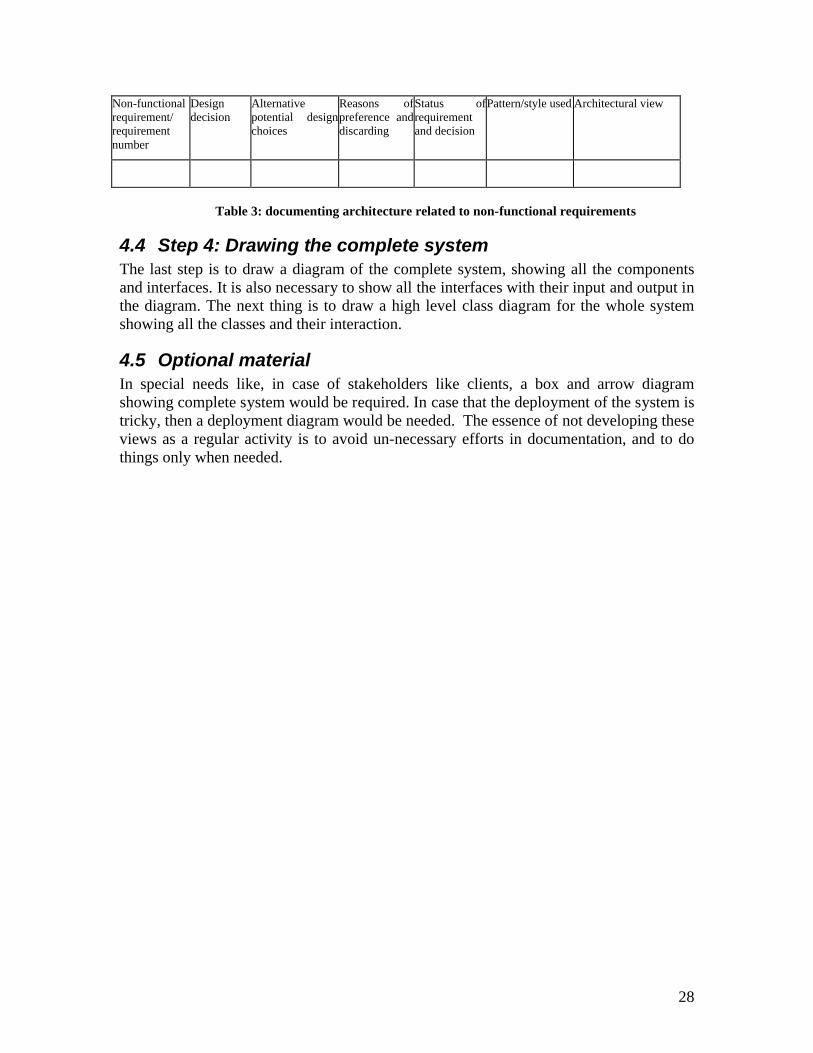
28
Non-functional requirement/ requirement number
Design decision
Alternative potential design choices
Reasons of preference and discarding
Status of requirement and decision
Pattern/style used Architectural view
Table 3: documenting architecture related to non-functional requirements
4.4 Step 4: Drawing the complete systemThe last step is to draw a diagram of the complete system, showing all the components and interfaces. It is also necessary to show all the interfaces with their input and output in the diagram. The next thing is to draw a high level class diagram for the whole system showing all the classes and their interaction.
4.5 Optional materialIn special needs like, in case of stakeholders like clients, a box and arrow diagram showing complete system would be required. In case that the deployment of the system is tricky, then a deployment diagram would be needed. The essence of not developing these views as a regular activity is to avoid un-necessary efforts in documentation, and to do things only when needed.
29
5. EvaluationThe following section compares the RFSAD method with existing methods to document SA. As mentioned previously in Chapter 2, the basis of this comparison will be the problems mentioned in SAD by researchers. In order to combine identified problems and to make a comparison easy, the following criteria are used. These criteria are derived from the limitations and problems of SAD mentioned in problem formulation section.
1. Degree of presence of design rationale2. Traceability between requirements and corresponding design decision3. Degree of addressing the needs of non technical stakeholders4. Description of reasons of neglecting or preference of potential design choices5. Degree of dynamism (in terms of number of views and degree of liberty in terms
of tailoring the specific SAD method to fit in with current needs)6. Degree of guidance and examples7. Degree of support in terms of recording history or iterations of design decisions.
These criteria are obtained after thorough literature study regarding software architecture documentation practices.
5.1 Comparison with established methods and standardsThere exists at least half a dozen software architecture documentation methods [5] and few of those methods are well known. These methods include Krutchen’s 4+1 view [13], IEEE 1471 SAD standard [12] and SEI’s V&B method [51]. From the section “Taxonomies of SAD methods” of this report, both IEEE 1471 and SEI’s V&B method can be categorized into similar one while 4+1 view method can be thought as a method with fixed set of views and hence can be positioned at the opposite pole in terms of number of architectural views with reference to both 1471 and V&B methods.
The IEEE 1471 standard can be regarded as the broader one or more generalized as compared to the V&B method as the V&B method focuses on tiny details of documentation as well as describes steps to develop architectural views, whereas the 1471 standard is abstract in nature and presents general guidelines for software architecture documentation.
For the purpose of the evaluation IEEE 1471 is chosen from both the V&B and the 1471 standard as it is broader in nature. Krutchen’s 4+1 view method is also chosen.
5.1.1 Degree of presence of design rationaleAccording to clause number 5.6 of the IEEE 1471 standard, an AD should include a rationale for the selected architectural components. The standard further states that the AD should provide evidence for the consideration of alternative potential architectural choices and the rationales for the chosen architectural concepts. The standard however does not provide examples of presenting architecture design rationales, and also lack in presenting documentation guidelines regarding capturing and presentation of design
30
rationales. Ian Gorton et. al. [11] has also mentioned that IEEE 1471 gives a definition of design rationale but has not further elaborated it.
V&B [51] mentions that AD should document design rationale, but it do not given any kind of guideline on how to document them. Moreover, the method also lacks in specifying which kind of information should be regarded as design rationale.Ian Gorton [11] have also described it as it is not clear from V&B that which kind of information should be captured as design rationale. Capilla et. al. [26] also mentioned that although V&B stresses the need of capturing architectural design rationales, but they do not mention how to record them for future use.
When design rationale representation in 4+1 view [13] method is considered, it does not provide any guidelines to capture or document design rationales. The main focus of 4+1 view method is to develop architectural views and not to document supplementary information associated with them. According to Tang [44] the 4+1 view model suggests using design decisions, but there is a little detail on how they should be documented and used.On the other hand the RFSAD method provides a way to capture and document design rationales and supplementary information related to different architectural views. Design decisions as well as different alternative design choices, reasons for preference and discarding can be documented by using the RFSAD method. It also provides a way to document different patterns or styles used during architectural process.
5.1.2 Traceability between requirements and corresponding design decisions
The IEEE 1471 standard in clause 5.2 states that an AD should identify stakeholders’ concerns considered by an architect while developing architecture of the system. These concerns can be regarded as having direct relationship with the system’s requirements, because stakeholders’ concerns stem from requirements of the system and vice versa. However in the IEEE 1471 standard, there is no explicit focus on documenting or relating requirements with the architectural choices made.
The 4+1 view method focuses on developing architectural views, and it does not present any guideline on how to develop and document traceability between requirements and architectural choices made. The RFSAD method on the other hand provides a way to link requirements and the relative design decisions. It also provides a way to record current status of the design decision.
5.1.3 Degree of addressing the needs of non-technical stakeholders
The IEEE 1471 standard in its clause 5.2 refers to identifying concerns of the stakeholders considered by architect. Some of the stakeholders mentioned in the standard are users, acquirers etc. which are generally non-technical in terms of understanding the complex architecture diagrams e.g. technical UML diagrams. The standard also don’t
31
hinders architect in choosing representation language of the architectural views, and it thus facilitates in understandability of the architectural concepts.
Researchers and practitioners have no clear understanding on the usage (in terms of diagram types in each view) of the 4+1 view method. According to [13] logical view represents the end user functionality, and since original article by Krutchen [13] presents architectural views in a language other than UML, there is a lot of confusion associated with choices of UML diagrams for each view. For example [14] describes that the logical view can be described by class diagram, sequence diagram or collaboration diagram, and the process view can be described by activity diagram, while [16] describes that the logical view is possible to document by class diagram and object diagram.
The question arises that how many percentages of end users are able to understand object diagram or class diagram or collaboration diagrams? The only view which depicts users’ interaction with the system is “Use case” view. But use case diagram do not convey sufficient information to user to understand it fully. As it is also described by [10] that UML do not help to understand the architectural aspects fully as it do not convey supplementary information attached with diagrams.
The RFSAD method allows architects to document architectural aspects of the system in such a way that non technical stakeholders can understand it. Step 5 of the RFSAD method allows architects to document architecture for non technical stakeholders in a language that they can understand, e.g. by using a box and arrow diagram. There is no restriction for the architect in choosing the view language.
5.1.4 Description of reasons of neglecting or preference of potential design choices
Clause 5.6 of the IEEE 1471 standard specifies that an AD should provide evidence of the consideration of the alternative architectural choices and rationales for the selected ones, which means that the IEEE 1471 standard stresses the need of capturing rationales for the architectural choices as well as, documenting the alternative design choices. However it does not provide guidelines on how to document them for future use.
The 4+1 view method does not focus on describing design choices; the main focus of 4+1 view method is to document the architectural views. The RFSAD method provides a way to document reasons (rationales according to the IEEE 1471 standard). Those reasons can be linked easily with requirements and hence traceability between requirements and design choices can be made easily.
5.1.5 Degree of dynamismThere is no limit in the IEEE 1471 in terms of the number of views. Any number of views can be developed to satisfy stakeholders’ needs. The standard revolves around stakeholders and their concerns and the main idea is to satisfy stakeholders’ needs. The standard is different from traditional SAD methods as stakeholder plays main role in architecture description. The traditional SAD methods are requirements driven, i.e.
32
architecture flows from a requirements document. But the IEEE 1471 standard places stakeholders in a position of prominence [7].
The 4+1 view method has five fixed number of architectural views, which constitutes to the logical, physical, development, process and use case views. Documenting architecture in limited set of views creates ambiguities for example satisfying more than one stakeholders needs in one view, which in turns creates lack of understandability (in terms of conveying architecture to stakeholders). [10] Describes that separate views for stakeholders, which are not haphazardly mixed, helps readers to digest information quickly and see how the system is structured into a set of well-separated but mutually-supporting design spaces.
Clements [10] also describes that 4+1 view method is limited to document architecture in a fixed set of views which hinders architects’ productivity. 4+1 view method also provides a little guidance towards tailoring of method in terms of neglecting certain views to meet the current documentation needs. The RFSAD method facilitates architects by providing them the liberty to develop as many views as they want. Those views are developed for all kinds of stakeholders ranging from technical stakeholders like detailed designers, implementers etc. to non technical stakeholders like clients and users etc.
5.1.6 Degree of guidance and available examples of implementationThe IEEE 1471 standard lacks in providing examples of implementation, and it has been understood differently by different researchers, for example [17] presents an interpretation of the IEEE 1471 standard which is different from [59] presentation of the SAD based on the IEEE 1471 standard. The reason of this is that, the standard only presents abstract guidelines for the architects and does not present examples or detailed guidelines.
The 4+1 view method has a tremendous amount of practical examples; perhaps it is one of the most commonly used SAD methods. But it suffers from the lack of available guidelines, and that is the reason behind different interpretations of practitioners in terms of UML diagrams for each 4+1 view. This creates confusion for the students, researchers and for the stakeholders.
The RFSAD method does not have any examples so far as it has not yet been implemented anywhere. The guidelines are very easy to follow, and the method is flexible to fit the needs of any kind of software system and stakeholder.
5.1.7 Degree of support in terms of documenting iterations of design decisions
Software architecture is an iterative process, and several design decisions are taken during that process. Design decisions also evolve by time and have their history which needs to be recorded [28]. Unfortunately none of the methods focus on recording the history or iterations of the design decisions.
33
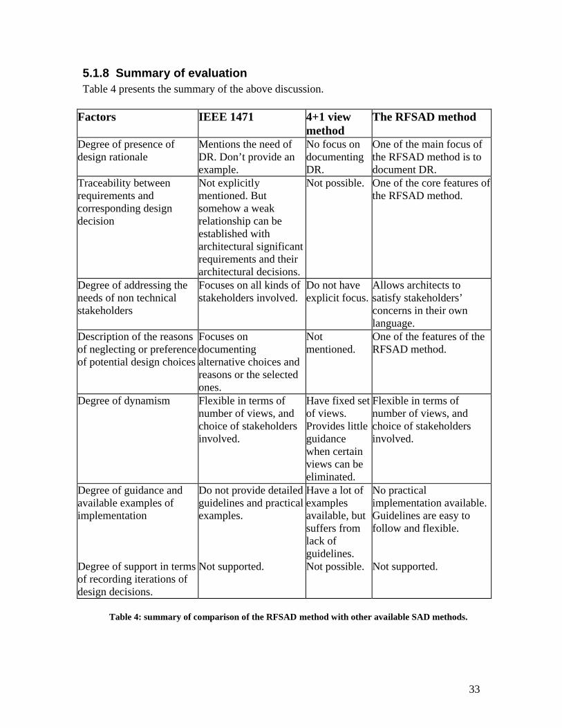
5.1.8 Summary of evaluationTable 4 presents the summary of the above discussion.
Factors IEEE 1471 4+1 view method
The RFSAD method
Degree of presence of design rationale
Mentions the need of DR. Don’t provide an example.
No focus on documenting DR.
One of the main focus of the RFSAD method is to document DR.
Traceability between requirements and corresponding design decision
Not explicitly mentioned. But somehow a weak relationship can be established with architectural significant requirements and their architectural decisions.
Not possible. One of the core features of the RFSAD method.
Degree of addressing the needs of non technical stakeholders
Focuses on all kinds of stakeholders involved.
Do not have explicit focus.
Allows architects to satisfy stakeholders’ concerns in their own language.
Description of the reasons of neglecting or preference of potential design choices
Focuses on documenting alternative choices and reasons or the selected ones.
Not mentioned.
One of the features of the RFSAD method.
Degree of dynamism Flexible in terms of number of views, and choice of stakeholders involved.
Have fixed set of views. Provides little guidance when certain views can be eliminated.
Flexible in terms of number of views, and choice of stakeholders involved.
Degree of guidance and available examples of implementation
Do not provide detailed guidelines and practical examples.
Have a lot of examples available, but suffers from lack of guidelines.
No practical implementation available. Guidelines are easy to follow and flexible.
Degree of support in terms of recording iterations of design decisions.
Not supported. Not possible. Not supported.
Table 4: summary of comparison of the RFSAD method with other available SAD methods.
34
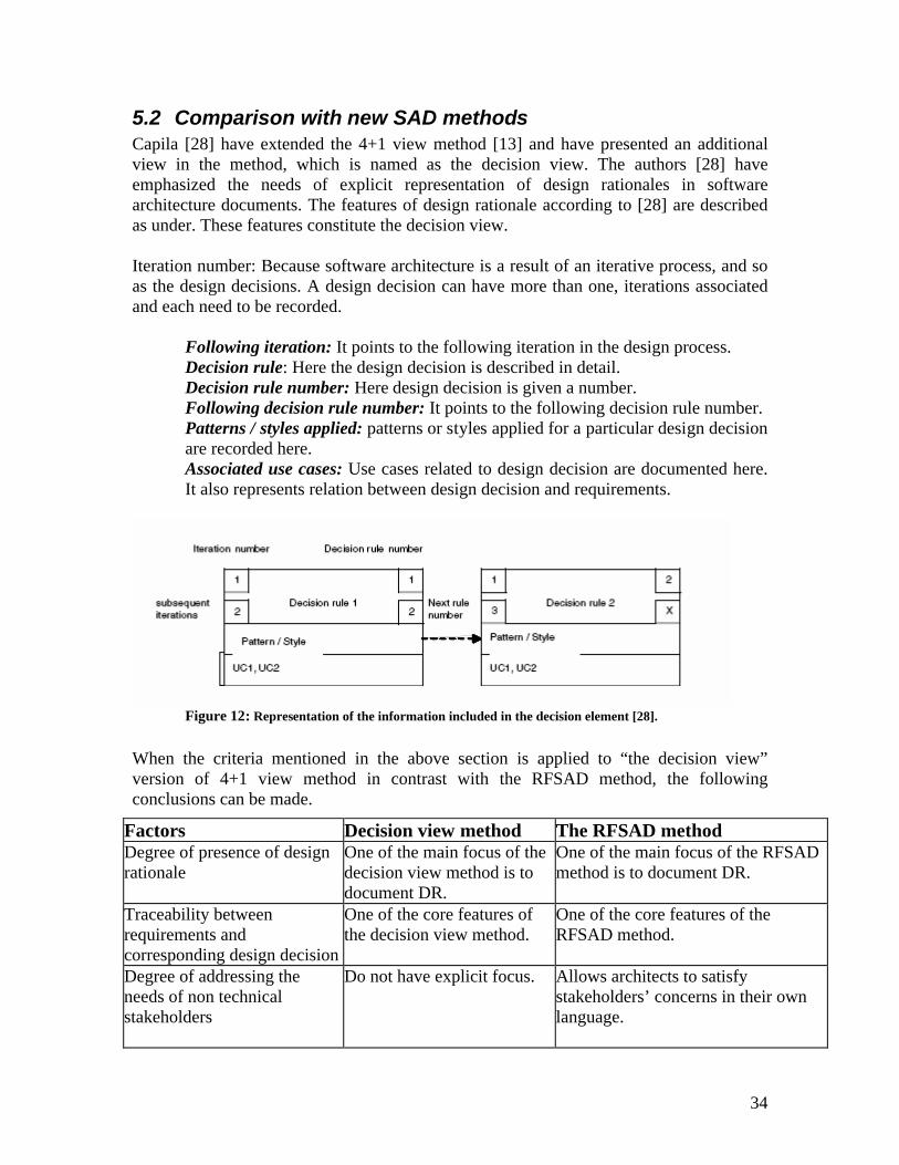
5.2 Comparison with new SAD methodsCapila [28] have extended the 4+1 view method [13] and have presented an additional view in the method, which is named as the decision view. The authors [28] have emphasized the needs of explicit representation of design rationales in software architecture documents. The features of design rationale according to [28] are described as under. These features constitute the decision view.
Iteration number: Because software architecture is a result of an iterative process, and so as the design decisions. A design decision can have more than one, iterations associated and each need to be recorded.
Following iteration: It points to the following iteration in the design process.Decision rule: Here the design decision is described in detail.Decision rule number: Here design decision is given a number.Following decision rule number: It points to the following decision rule number.Patterns / styles applied: patterns or styles applied for a particular design decision are recorded here. Associated use cases: Use cases related to design decision are documented here. It also represents relation between design decision and requirements.
Figure 12: Representation of the information included in the decision element [28].
When the criteria mentioned in the above section is applied to “the decision view” version of 4+1 view method in contrast with the RFSAD method, the following conclusions can be made.
Factors Decision view method The RFSAD methodDegree of presence of design rationale
One of the main focus of the decision view method is to document DR.
One of the main focus of the RFSAD method is to document DR.
Traceability between requirements and corresponding design decision
One of the core features of the decision view method.
One of the core features of the RFSAD method.
Degree of addressing the needs of non technical stakeholders
Do not have explicit focus. Allows architects to satisfy stakeholders’ concerns in their own language.
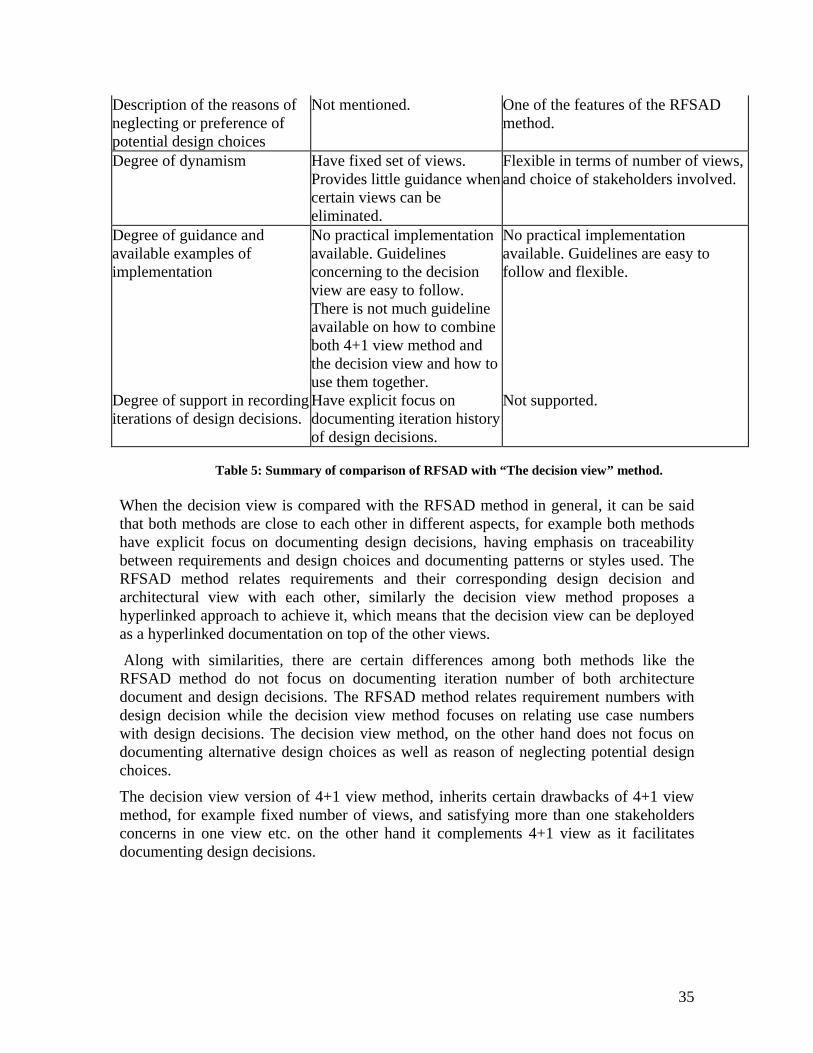
35
Description of the reasons of neglecting or preference of potential design choices
Not mentioned. One of the features of the RFSAD method.
Degree of dynamism Have fixed set of views. Provides little guidance when certain views can be eliminated.
Flexible in terms of number of views, and choice of stakeholders involved.
Degree of guidance and available examples of implementation
No practical implementation available. Guidelines concerning to the decision view are easy to follow. There is not much guideline available on how to combine both 4+1 view method and the decision view and how to use them together.
No practical implementation available. Guidelines are easy to follow and flexible.
Degree of support in recording iterations of design decisions.
Have explicit focus on documenting iteration history of design decisions.
Not supported.
Table 5: Summary of comparison of RFSAD with “The decision view” method.
When the decision view is compared with the RFSAD method in general, it can be said that both methods are close to each other in different aspects, for example both methods have explicit focus on documenting design decisions, having emphasis on traceability between requirements and design choices and documenting patterns or styles used. The RFSAD method relates requirements and their corresponding design decision and architectural view with each other, similarly the decision view method proposes a hyperlinked approach to achieve it, which means that the decision view can be deployed as a hyperlinked documentation on top of the other views.
Along with similarities, there are certain differences among both methods like the RFSAD method do not focus on documenting iteration number of both architecture document and design decisions. The RFSAD method relates requirement numbers with design decision while the decision view method focuses on relating use case numbers with design decisions. The decision view method, on the other hand does not focus on documenting alternative design choices as well as reason of neglecting potential design choices.
The decision view version of 4+1 view method, inherits certain drawbacks of 4+1 view method, for example fixed number of views, and satisfying more than one stakeholders concerns in one view etc. on the other hand it complements 4+1 view as it facilitates documenting design decisions.
36
6. Related workThere must be no doubt that researchers now have realized the importance of software architecture documentation. Some limitations and drawbacks in current SAD standards have been identified by research community as described in the theory chapter (Chapter X). One of the biggest drawbacks is about giving less importance to design rationales in SAD practices. In the conferences EWSA2005 [56] and WICSA2005 [57] both experts and attendees stressed the need of expressing and managing design decisions in software architecture documentation [26].
Efforts to capture and use design rationale are being addressed by researchers and practitioners in different aspects. New SAD methods are being developed with explicit focus on design rationales for example [28]. Another aspect of the addressing design rationales, are the ongoing efforts of development of DR capture tools and methodologies. Efforts regarding addressing DR in SAD methods are already described in the “comparison with new SAD methods” and “future of SAD methods” sections. In this section efforts regarding, development of DR capture tools is described along with defining DR and description of significance of DR in the views of researchers.
6.1 Design rationaleAccording to American heritage dictionary [27] rationale means “The fundamental reason or basis, an exposition of principles or reasons “. From the above definition is can be concluded that the word design rationale means a fundamental reason for the proposed design. Ian Gorten et al [9] define design rationale as “Design rationale (DR) captures the knowledge and reasoning justifying the resulting design. This includes how a design satisfies functional and quality requirements, why certain designs are selected over alternatives and what type of system behavior is expected under different environmental conditions”.
Capilla et.al. [28] define design rationale as “Design decisions represent the cornerstone to obtain suitable software architectures because they represent the rationale that motivated the election of architectural patterns and styles, the functional blocks that represent systems and subsystems in the architecture, the relationships among them and the control of the architecture”.
6.1.1 Significance of DR in the views of researchersIn usual practice after analyzing requirements, an architect takes some decisions and draws software architectural diagrams/views. And those architectural views are used in later stages of software development process, here a fundamental issue remains that those architectural views fail to present design decisions taken earlier by the software architect. All those design rationales are lost from documentation and becomes tacit knowledge of the architect. It creates a lot of problems in later stages of software development process. Some of them are indicated by Jon Bosch [8, 29] like, due to cross cutting and intertwined nature of design decisions; these can be easily violated in case of traditional software architecture documentation and can lead to high maintenance cost.
37
From the definition of software architecture presented by Jon Bosch[8], software architecture community can be divided into two groups, one believing in traditional components and connector definition of software architecture, while the other school of thought seems convinced by Jon Bosch’s[8] definition. He stress that the problem faced by software development community in later stages of development process can be solved by changing the traditional definition of software architecture from “combination of components and connectors” to “set of architectural design decisions/rationales”. Bosch stresses the need of explicit representation of design decision in architecture documentation.
The need of presenting architectural design decisions is mentioned by other researchers as well like [15] and [52]. Ian Gorton et. al. [15] describes that lack of systematically capturing and using architectural knowledge can greatly affect organization’s architecture capability, and all the design decisions, pattern used and other knowledge related to architecture becomes the tacit knowledge of the architect. Tyree et. al. [52] stresses that while documenting software architectures, design decisions should be documented first followed by architectural views.
6.1.2 Tools to capture and use of DRThere are a number of tools available to capture design rationales. Some of them are developed in 1970s e.g IBIS [30], the others have the origin in 1980s and 1990s e.g. QOC [31] and DRL [32]. There are some tools which have their origin in 2005 e.g. SeuRAT [33], ADDT [34], SYSIPHUS [35]. The purpose of mentioning this is to clarify that design rationale tools and methods are being used from almost 37 years and are becoming more contemporary day by day. E.g. IBIS [30] was changed to gIBIS [36] after introduction of a hypertext tool, which allowed users to browse, and see the hierarchical indexes of all nodes and links.
The invention of groupware aware DR tools also strengthens the claim. DRL [32] was used to implement a DR management system named SIBIL [37] to facilitate practitioners to manage DR according to DRL method, in a software system. Dutoit et. al. [38] Describes that although researchers have focused on improving DR capture tools and methods, the alignment of DR tools with software engineering processes has not yet happened. This kind of integration will give birth to a rationale centered development process and will be helpful in both system modeling and project management decision making.
However, SeuRAT [33] can be regarded as an effort to bridge the above mentioned gap. There are some other efforts e.g. [26, 28] and [8, 29] which stress the need of explicit representation of DR in software architecture. But they are more focused towards incorporating DR in software architecture than in the software engineering process. Although it is true that, a DR in software architecture documentation, indirectly shows presence of DR in software engineering process.
There is a need to take measures to align rationale management tools and methods regardless of their nature (DR for architecture and design, Rationale management for
38
requirements, Rationales for project management, etc.) into software engineering process. Rather than focusing more on inventing new methods and tools, efforts should be made to incorporate already developed tools into software process and hence start a maturity process of these tools and methods which will eventually become basis of new and improved tools and techniques better aligned with software process and would be more useful.
In this section some of the tools are described in order to give a short introduction of them. As the reader will read through these mentioned tools, it will become clear that there is a gradual shift towards alignment with software process i.e. tools are becoming more and more process focused (they are trying to become part of software process in order to be used) not just remain a set of formal detailed discussion on design rationales.
6.1.2.1 gIBISIssue Based Information System (IBIS) [48] was developed to tackle “Wicked” problems. Wicked problems can be defined as problems which don’t have a clear solution, or problems which don’t have a clear problem definition. [39]. IBIS have three basic elements i.e. Issues, Positions and Arguments.
Issues: Issue can be a problem or a question, for which decision have to be made.e.g. How to save applicants’ pictures in the database?
Position: Position can be regarded as the potential solutions or answers to the issue. There could be more than one position for a certain issue. There could be more than one solution, and each one would be referred as position e.g. Position 1: Save them as binary fields.Position 2: Save them as OLE object.
Arguments: Arguments are made to satisfy or answer the positions made earlier. An argument can support or oppose a position. e.g. Argument 1: OLE object will run only on Microsoft platform.
In 1988 IBIS was implemented with a hyper text based tool, in order to view hierarchical indexes of nodes and links [40] and named as gIBIS. QuestMap [41] incorporated gIBIS approach and presented a tool as an online whiteboard. Compendium institute [42] has enhanced the “QuestMap” and now has offered a lot of new and enhanced features as a new software named compendium, available at [43].
6.1.2.2 QOCQOC [31] is a notation, which consists of questions as main element of the QOC. Question can be referred as the problem to be solved. The second element in QOC is Option, which is the possible option/alternative choice to solve the question, and third element in the QOC is criteria, it is used to asses or compares different design options. [44].
39
6.1.2.3 DRLDRL [32] consists of four basic elements i.e. goal, question, claim and alternative. A goal expresses criteria to be satisfied. A question arises from goal to be answered. Claimsare the possible answers to the questions. It is not mandatory for a claim to satisfy the goal. Goal has its alternatives, and their relation with goal could be that whether they are good alternative or not? [44]. The DRL concept is implemented as SIBYL [37] which allows users to manipulate rationale management according to DRL.
6.1.2.4 SeuRATSoftware Engineering Using Design RATionale (SeuRAT) [33] is an Eclipse [49] plug-in, which captures rationales into a database, which can be used later during maintenance phase, or when systems are extended or re-used. It is a rationale management tool integrated in software development environment, allowing software developers to record rationales during software development. [45]. A key difference between SeuRAT and DRL is that SeuRAT has incorporated the concept of requirements (both functional and non-functional) instead of goals [44]. SeuRAT can therefore be regarded as an effort to align DR methods with software engineering process.
6.1.2.5 Architecture Decision Description Template (ADDT)ADDT [34] is a practical approach to capture architectural design rationales. Instead of formal discussions on DR details and their representations, ADDT have presented a template to capture decision rationales. ADDT has a number of key elements. It captures comprehensive information and the knowledge captured is useful during and after the architectural design phase. Authors of ADDT argue that the information captured is enough to interact with other phases and artifacts of software engineering process [44].
Presence of key elements like issue, decision, status, assumptions, constraints, related decisions, related requirements, related artifacts, related principles, notes etc. gives enough details about an architectural issue, its related decision, status of that decision or status of other related decisions, assumptions made during that decision, constraints for that decision, related requirements, artifacts and principles. Related requirements serves ADDT to cross boundary of software architecture and produce an overlap or link between the two phases. Related artifacts link architectural decisions with other artifacts of the process. ADDT hence can be regarded as a model which provides DR capture, DR presentation and DR management guidelines and also have a strong association with software architecture and relatively weak association with software engineering process as well.
6.1.2.6 SYSIPHUSSYSIPHUS [35] up to my knowledge is the best available tool in a sense that it incorporates design rationales, system requirements and software design and testing phases by linking them each other through a common repository. In the same time it demands minimum possible process knowledge, in order to allow SYSIPHUS to accommodate projects following any software engineering process. It also allows collaborative work as more than one user can work on the same model at same time.
40
The main purpose of SYSIPHUS is to facilitate teachers in academic projects. They now don’t have to recommend students to use different tools for different processes. Sometimes students have to use different tools in the same project e.g. they use different tool during requirement phase, during design phase some other tool is being used and similarly in testing phase another tool is used. Students have to share files with each other in order to review each other’s work and they have to wait if some other is working on the same model.
All those difficulties are now removed because of SYSIPHUS and students now can use the same tool for the whole project regardless of software engineering process. Rationales are maintained using a refined version of QOC [31] method [46]. Administrator can create new users for SYSIPHUS, and can assign different rights to them. Templates for different documents can be defined, edited or deleted based upon the project need [47].
All the above mentioned features are deeply needed to be incorporated into practical software development projects. There is a need of empirical evidence of SYSIPHUS in software development industry rather than in academia. SYSIPHUS can be greatly enhanced by learning from that industrial experience, as it has great potential to be one of the leading tools used in industry.
41
7. DiscussionThe awareness of presenting design rationales in SAD is increasing in the architecture community. Researchers in WISCA2007 [58] have stressed the importance of presenting design rationales in SAD. In WISCA2005 [57] researchers and participants have also advocated the need of first class representation of design rationales in SAD [26].
Various researchers and universities are actively involved in identifying weaknesses in current SAD methods and presenting solutions to overcome problems caused by ignoring design decisions while documenting SA. Computer science department of University of New South Wales, Australia, Computer science department of Groningen University Netherlands and University of Ray Juan Carlos, Madrid are worth mentioning.
Ian Gorton et. al from University of New South Wales, has analyzed problems in existing SAD methods particularly regarding representation and usage of design rationales. Jon bosch from Groningen University have presented a new definition of software architecture, according to that a software architecture should be seen as a set of design decisions rather then a combination of components and connectors.
Capilla et. al. from University of Ray Juan Carlos has presented an approach to describe design decisions in software architecture document. They have proposed a new view called decision view in combination with famous 4+1 view [14] model. The RFSAD method is an effort to complement current research in the field of software architecture documentation.
7.1 Strong points of the RFSAD methodThe RFSAD method has several advantages over other existing SAD methods. Those advantages are mentioned as under.
1. Explicit representation of DR2. Traceability between requirements and DR3. Focus on satisfying concerns of stakeholders4. Facilitate on documenting alternative potential design choices and reason of
neglecting them.5. Unlimited number of architectural views6. Complement existing SAD methods and can be used easily in combination with
them.7. Easy to use and flexible8. Better requirements management with the help of emergent qualities9. Integrated with the software development process
All the above advantages are already described in evaluation chapter except better requirements management thing which is explained in the RFSAD method’s description. One thing is worth mentioning here, which is not already described else ware and it is about complementing existing SAD methods.
42
As it is obvious from the theory chapter that all the existing SAD methods focus more on developing architectural views than documenting design rationales, and there is a clear lack of explicit representation of DR in those SAD methods. The RFSAD method on the other hand have clear focus on documenting and capturing DR and do not have an explicit methodology defined to develop architectural views. When the RFSAD method is used in combination with any existing SAD method, the DR part can be documented by using the RFSAD method and views development part can better be accomplished by a method of choice. Capilla [26] has presented the same concept of documenting DR by using the decision view, while documenting traditional architectural views by using 4+1 view method.
The second thing which is also worth mentioning is about integration with the software development process. In a traditional software development process architecture serves as a hub between requirements and detailed design phase. Architectural statements (decisions) serve as a basis for the detailed design. A SAD with no explicit link between both (requirements and detailed design) or any one of them can create an isolation or in-consistency between the two above mentioned phases. In that case it is obvious that the underlying SAD method, on which that architecture document is based, will be hard to adopt and to become part of the software development process.
The RFSAD method not only links requirements and design decisions, the detailed design artifacts can be linked with corresponding architectural decision. Moreover testing artifacts e.g. test cases can also be linked with emergent qualities (emergent requirements) to increase traceability and eventually the traceability within the major phases of the software development process can be achieved. It makes the RFSAD method more beneficial and easy to adapt and implement.
7.2 LimitationsAlong with several advantages, the RFSAD method on the other hand posses some limitations as well. Following is the description of those limitations.
7.2.1 Limitations of RFSAD methodThere is no tool support for the RFSAD method so far, which makes it difficult to use, and hence is another limitation associated with the RFSAD method. A lot of traceability makes the RFSAD method difficult to follow, laborious and time consuming, which also arises the strong need of tool support for the RFSAD method.
The method is developed by keeping in mind the requirements of traditional software development methodologies. There is no empirical evidence available, which claim the effectiveness of the RFSAD method in agile software development processes. Design decisions evolve over time and all iterations of a design decision should be recorded for future use. The RFSAD method does not focus on documenting history of design decisions.
43
7.2.2 Limitations of workThe evaluation of RFSAD method is not empirical. Lack of time and resources are the main hurdle behind not doing a thorough evaluation of the RFSAD method.
Lack of empirical proof of the advantages claimed is the biggest limitation so far in the RFSAD method. There is a need to test the RFSAD method empirically along with other established methods.
7.3 Future of SAD methods and standardsIn this section future trend in SAD methods are described in terms of presenting design rationales. Furthermore the new revision of the IEEE 1471 standard is summarized in section 7.3.2.
7.3.1 DR trend in SAD methodsCapilla et. al. [28] has presented an approach to describe design decisions in software architecture document. They have proposed a new view called decision view in combination with famous 4+1 view [14] model. Jon Bosch and Jansen are developing an approach called Archium [29] to better present design rationales alone with traditional architectural views. Archium is a language which extends Java for supporting components and connectors. They have developed a prototype which consists of a compiler and a run time environment [26].
Tyree and Akerman [34] have developed an approach where architecture decision model can be seen as a network of dependencies between decisions [26]. Babar et. al. [22] has presented a process-centric architecture knowledge management environment (PAKME) approach, to capture and manage architectural knowledge. The two main objectives of PAKME are [22]:
To provide a support mechanism for capturing, managing, and retrieving architecture knowledge to improve the quality of architecture activities.
To act as a source of architecture knowledge for those who need rapid access to experience-based design decisions to assist in making new decisions or discovering the rationale for past decisions.
From the section “DR tools” it is clear that these tools can play an important role in inclusion of DR in software development process. There is a need to align both DR tools and SAD methods with software development process. That can be achieved by getting benefit from both DR tools and SAD methods at the same time, one way to accomplish this is to develop tools for existing SAD methods and existing DR capturing tools can be used either in combination with them or as a part of those SAD tools.
7.3.2 Reflections on the new version of the IEEE 1471 SAD standardIEEE has published a first working draft (WD1) of a revised version of the IEEE 1471 standard in July 2007. ISO now have adopted 1471 standard and it is now also called ISO/IEC 42010. The next ISO working group meeting (WG 42) regarding ISO/IEC
44
42010 is due to be held in November 2007 in Montreal to develop the next working draft [60].
The revision goals of this standard are harmonization with the ISO 15288 [11] standard concerned with systems engineering, system lifecycle processes and the ISO 12207 [46] standard concerned with IT, software lifecycle processes, and alignment with other ISO architecture-related efforts. According to this draft version, IEEE 1471 was widely accepted due to multiple viewpoints to describe architectures and, due to the feature of placing stakeholders as primary motivation for the architectural descriptions.
In the revised version of the standard, there is more focus towards elaboration and explanation of the specifications. Clauses are exemplified. An architectural description template is also given at the end and viewpoints are explained with examples. A lot of changes are made as compared to the predecessor version of standard, for example library viewpoints are now renamed as viewpoints. It has now been specified in the standard that a viewpoint will have exactly one resultant view.
The clause 6 in the ISO/IEC 42010 standard [60] (which defines the core part of the document) has some additions when compared with the previous version. One important addition in the standard is its emphasis on conformance with other existing SAD methods. The need of that concept is already discussed in strong points of the RFSAD method section. In the clause 6.3, note 2, the standard mentions that by selection of suitable viewpoints the conformance with existing SAD methods can be achieved.
In the clause 6.4, note 1, it is mentioned that a complex system can be described by different components as well as system as a whole. In that case both kinds of views (views of parts of the system and views of the complete system) can be developed. This is analogous to the V&B approach, where a system is decomposed into different components and views of each components are separately developed and then are interrelated in the “Beyond” part. In the previous version of the standard it was mandatory for the architectural views to show the complete system.
In the clause 6.4.1 architectural views are categorized and a new phenomenon is described. That is about “Architectural models”. According to the standard an architectural model is:
“Architectural models provide a mechanism to modularize architectural views. There are cases when a view may need to use more than one language, notation or modeling technique to address all of the concerns assigned to it. To do this, a view may consist of multiple architectural models. Each model may use a distinct language, notation, or model type, as defined by its viewpoint.”
The clause 6.6 is about architecture rationales, and the standard categories the rationales as “viewpoints rationales”, “view rationales” and “model rationales”. The clause 6.3.3 of ISO/IEC 15288 [11] is recommended for decision capture and tracking. A new clause is added for describing architecture for multiple systems of concern, which describes that if

45
two systems are architecturally related by concerns, then the viewpoints selected for framing those concerns shall be the same in each system's architectural description.
As mentioned above the ISO/IEC 42010 [60] standard have presented a way to develop conformance between different SAD standard. The need of the same concept is also presented in the strong points of RFSAD method.
46
8. ConclusionIt is clear that current SAD methods lack in capturing and documenting design rationales. Now researchers have realized the importance of documenting design decisions and how that information can be useful in the future. A lot of problems have been identified due to the lack of explicit focus on design rationales. There is a gradual shift in considering SA as combination of architectural decisions rather than considering it in traditional components and connectors format. There is a need to understand that shift and adapt existing and future SAD methods to address the need of capturing and documenting design decisions.
There is also a need to develop compatibility between different SAD methods so that they can complement each others. Stakeholders’ needs in terms of communicating architectural knowledge should also be taken care. The proposed RFSAD method is an effort towards achieving these goals, but the true benefits of the RFSAD method are yet to be discovered by empirically analyzing it in comparison with different existing SAD methods and testing it in different projects of various natures while using different software development methodologies.
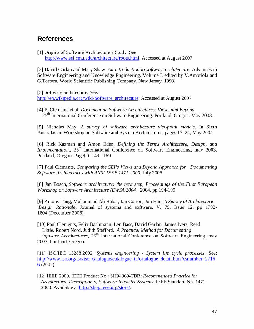
47
References
[1] Origins of Software Architecture a Study. See: http://www.sei.cmu.edu/architecture/roots.html. Accessed at August 2007
[2] David Garlan and Mary Shaw, An introduction to software architecture. Advances in Software Engineering and Knowledge Engineering, Volume I, edited by V.Ambriola and G.Tortora, World Scientific Publishing Company, New Jersey, 1993.
[3] Software architecture. See: http://en.wikipedia.org/wiki/Software_architecture. Accessed at August 2007
[4] P. Clements et al. Documenting Software Architectures: Views and Beyond. 25th International Conference on Software Engineering. Portland, Oregon. May 2003.
[5] Nicholas May. A survey of software architecture viewpoint models. In Sixth Australasian Workshop on Software and System Architectures, pages 13–24, May 2005.
[6] Rick Kazman and Amon Eden, Defining the Terms Architecture, Design, and Implementation,, 25th International Conference on Software Engineering, may 2003. Portland, Oregon. Page(s): 149 - 159
[7] Paul Clements, Comparing the SEI’s Views and Beyond Approach for Documenting Software Architectures with ANSI-IEEE 1471-2000, July 2005
[8] Jan Bosch, Software architecture: the next step, Proceedings of the First European Workshop on Software Architecture (EWSA 2004), 2004, pp.194-199
[9] Antony Tang, Muhammad Ali Babar, Ian Gorton, Jun Han, A Survey of Architecture Design Rationale, Journal of systems and software. V. 79. Issue 12. pp 1792-1804 (December 2006)
[10] Paul Clements, Felix Bachmann, Len Bass, David Garlan, James Ivers, Reed Little, Robert Nord, Judith Stafford, A Practical Method for Documenting Software Architectures, 25th International Conference on Software Engineering, may 2003. Portland, Oregon.
[11] ISO/IEC 15288:2002, Systems engineering - System life cycle processes. See: http://www.iso.org/iso/iso_catalogue/catalogue_tc/catalogue_detail.htm?csnumber=27166 (2002)
[12] IEEE 2000. IEEE Product No.: SH94869-TBR: Recommended Practice for Architectural Description of Software-Intensive Systems. IEEE Standard No. 1471- 2000. Available at http://shop.ieee.org/store/.
48
[13] ]Philippe Kruchten , Architectural Blueprints—The “4+1” View Model of Software Architecture, Software, IEEE Volume 12, Issue 6, Nov 1995
[14] Mikko konito, Introducing the 4+1 view model. See: http://www-128.ibm.com/developerworks/wireless/library/wi-arch11/ February 2005.
[15] M. Ali Babar, I. Gorton, and R. Jeffery. Toward a Framework for Capturing and Using Architecture Design Knowledge. Technical report unsw-cse-tr-0513,The University of New South Wales, June 2005
[16] Gert Florijn UML - The Unified Modeling Language An overview
[17] Henk Koning, Hans van Vliet , A method for defining IEEE Std 1471 viewpoints, Faculty of Science Vrije Universiteit, Amsterdam De Boelelaan 1081a,1081 HV Amsterdam, The Netherlands. 2003
[18] Per Sundblad, Business Improvement Through Better Software Architecture, The architecture journal. See: http://msdn2.microsoft.com/en-us/library/bb266336.aspxJanuary 2007.
[19] Lex Bijlsma, Software architecture. See: http://www.cs.uu.nl/wiki/Master/SoftwareArchitecture. Accessed at October 2007.
[20] Software architecture for software intensive systems. See: http://www.sei.cmu.edu/architecture/ . Accessed at October 2007
[21] Design research in information systems. See:http://www.isworld.org/Researchdesign/drisISworld.htm Accessed at August 2007
[22] Muhammad Ali Babar, Ian Gorton, A tool for managing software architecture knowledge, Proceedings of the Second Workshop on SHAring and Reusing architectural Knowledge Architecture, Rationale, and Design Intent SHARK-ADI '07, 2007
[23] Frank Buschmann, Regine Meunier, Hans Rohnert, Peter Sommerlad, MichaelStal. Pattern-Oriented Software Architecture—A System of Patterns. New York, USA:Wiley and Sons, 1996
[24] Rick Kazman, Amon Eden, Abstraction classes in software design. IEEE software vol. 153, No (4) August 2006. pp.163-182.
[25] Software architecture definition. See: http://www.pcmag.com/encyclopedia_term/0,2542,t=software+architecture&i=51662,00.asp. Accessed at September 2007
49
[26] Rafael Capilla, Francisco Nava , Sandra Pérez , Juan C. Dueñas. A web-based tool for manageing architectural design decisions. ACM SIGSOFT software engineering notes. V. 31, Issue 5, (2006)
[27] The American Heritage® Dictionary of the English Language, Fourth Edition. Retrieved June 18, 2007, from Dictionary.com website: http://dictionary.reference.com/browse/rationale
[28] Juan C. Dueñas and Rafael Capilla. The Decision View of Software Architecture. Second European workshop on software architecture, EWSA 2005, pp 222-230. (2005)
[29] A. Jansen; J. Bosch, Software Architecture as a Set of Architectural Design Decisions. WICSA 2005. 5th Working IEEE/IFIP Conference on Software Architecture, pp. 109 – 120. (2005).
[30] W. Kunz and H. Rittel, Issues as Elements of Information Systems. Center for Planning and Development Research,University of California at Berkeley, (1970).
[31] A. Maclean, R. Young, V. Bellotti, and T. Moran, “Questions, Options and Criteria:Elements of Design Space Analysis,” in Design Rationale: Concepts, Techniques and Use, T. Moran and J. Carroll, Eds. Lawrence Erlbaum Associates, 1996, ch. 3, pp. 53–106.
[32] J. Lee and K. Lai, “What’s in Design Rationale,” in Design Rationale: Concepts, Techniques and Use, T. Moran and J. Carroll, Eds. Lawrence Erlbaum Associates, 1996, ch. 2, pp. 21–52.
[33] J. Burge, “Software Engineering Using design RATionale,” Ph.D. dissertation, Worcester Polytechnic Institute, 2005
[34] J. Tyree and A. Akerman, “Architecture Decisions: Demystifying Architecture,” IEEE Software, vol. 22, no. 2, pp. 19–27, 2005.
[35] T. Wolf and A. H. Dutoit, ‘‘Sysiphus: Combining System Modeling with Collaboration and Rationale,’’ Institut für Informatik, Technische Universität MünchenLehrstuhl für Angewandte Softwaretechnik (November 2004)
[36] Conklin & Begeman (1988), gIBIS: A Hypertext Tool for Exploratory Policy Discussion, ACM Transactions on Office Information Systems, Vol 6, No 4, October 1988, Pages 303-331
[37] J. Lee, “SIBYL: A Tool for Managing Group Decision Rationale,” in Proceedings of the Conference on Computer-Supported Cooperative Work, 1990, pp. 77–92.
[38] Allen H. Dutoiti and Barbara, Rationale management in software engineering peachTechnische Universität München Institut für Informatik Munich, Germany (2000)
50
[39] An Approach for the Capture of Requirements and Design Rationale for Software Engineering Education Projects Martin Purvis Computer and Information Science University of Otago Dunedin, New Zealand, Software Education Conference, 1994. 22-25 Nov 1994 Page(s):261 - 266
[40] Issue based information systems. See:http://www.cs.ucl.ac.uk/staff/S.Stumpf/Reports/IN9801.html. Accessed at: August 2007
[41] GDSS: QuestMap. Group Decision Support Systems, Washington, USA http://www.gdss.com/OM.htm. Accessed at: August 2007
[42] The compendium institute. See: http://www.compendiuminstitute.org. Accessed at September 2007
[43] Compendium download, See: http://www.compendiuminstitute.org/download/download.htm. Accessed at September 2007
[44] Antony Tang, A rationale-based model for architecture design reasoning. Ph.D. Thesis, Faculty of ICT, Swinburne University of technology. (February, 2007)
[45] Software engineering using RATionale. See: http://www.users.muohio.edu/burgeje/SEURAT/. Accessed at September 2007
[46] ISO/IEC 12207:1995, Information technology -- Software life cycle processes. See: http://www.iso.org/iso/iso_catalogue/catalogue_tc/catalogue_detail.htm?csnumber=21208 (1995)
[47] Allen H. Dutoit, Timo Wolf , Using Rationale for Software Engineering Education 18th Conference on Software Engineering Education & Training (CSEET'05), 18-20 April 2005 Page(s): 129 - 136
[48]H. Rittel and W. Kunz., "Issues as Elements of Information Systems", Working Paper No. 131, Institute of Urban and Regional Developmen& Univasity of California at Berkeley, 1970.
[49] The eclipse software. See: www.eclipse.org. Accessed at September 2007
[50] Per Kroll and Philippe Kruchten. The Rational Unified Process Made Easy: A Practitioners Guide to the RUP. Addison-Wesley, 2003.
[51] Clements, P., F. Bachmann, L. Bass, D. Garlan, J. Ivers, R. Little, R. Nord, J. Stafford. Documenting Software Architectures: Views and Beyond. Addison- Wesley, Boston, 2002
51
[52] Tyree, J. and A. Akerman, Architecture Decisions: Demystifying Architecture. IEEE Software, 2005. 22(2): p. 19-27
[53] L. Bass, P. Clements, and R. Kazman. Software architecture in practice 2nd ed. Addison Wesley, 2003.
[54] Rational Unified Process, See: http://www-306.ibm.com/software/awdtools/rupAccessed at: September 2007
[55] DOJ System development lifecycle guidance, See: http://www.usdoj.gov/jmd/irm/lifecycle/ch1.htm. Accessed at October 2007
[56] 2nd European workshop on software engineering, See: http://www.arch-ware.org/ewsa/2005/ , June 2005
[57] 5th IEEE working conference on software architecture, See: http://wwwp.dnsalias.org/wiki/5th_WICSA_2005, November 2005.
[58] 6th IEEE working conference on software architecture, See: http://wwwp.dnsalias.org/wiki/Current_events. (January 2007)
[59] Nick Rozanski and Eoin Woods, Software Systems Architecture: Working with Stakeholders Using Viewpoints and Perspectives. Addison-Wesley Professional. April 2005
[60] ANSI/IEEE 1471: ISO/IEC 42010 standard. See: http://www.iso-architecture.org/ieee-1471/ Accessed at October, 2007.