Embed Size (px)
Citation preview
Faculty of Science and Technology
MASTER’S THESIS
Study program/ Specialization: Master of Science in Petroleum Engineering, Drilling and Well Technology
Spring semester, 2013
Open
Writer: Torleiv Midtgarden …………………………………………
(Writer’s signature) Faculty supervisor: Helge Hodne, University of Stavanger External supervisor(s): Sverre Bakken, Archer Oiltools
Title of thesis: Advancement in P&A operations by utilizing new PWT concept from Archer
Credits (ECTS): 30
Key words: Plugging, Abandonment Perforate, wash, cement Time Estimation
Pages: 85
+ enclosure: 5
Stavanger, 17th of June 2013 Date/year

Advancement of P&A operations by utilizing new PWT concept from Archer
Master thesis by
Torleiv Midtgarden
University of Stavanger Department of Petroleum Technology
June 2013

Advancement of P&A operations by utilizing new PWT concept from Archer
iii
Abstract Many of the oil and gas fields on the Norwegian continental shelf (NCS) are approaching the end of field life. The Petroleum safety authority of Norway is putting pressure on the Exploration and Production (E&P) companies and demanding final field permanent plug and abandonment of several fields within a short period of time. Especially the temporary plugged and abandoned wells [1]. Over the next 5 to 25 years, several thousand wells will need to be plugged and abandoned on the NCS [2]. The conventional method for Plug and abandonment (P&A) includes casing removal by milling operations in order to access the formation for barrier placement. This conventional P&A activity is considered by E&P companies as time consuming, costly and causes additional risks related to health, safety and environment (HSE). Thus a growing interest has been put into finding new methods and solutions to reduce the time and cost of such operations. Archer recognizes this need, and has put effort in developing new intelligent concepts and technical solutions to overcome these challenges. As a result, the Perforate and Wash Tool (PWT) has been introduced. The PWT tool is designed to perforate a selected casing or liner section, wash and clean the perforated section completely, prior to placing a cross sectional cement plug. By eliminating the need for section milling and debris handling, and preparing the seal zone to receive cement, the PWT concept delivers a step change in P&A efficiency and effectiveness. Over the last years this PWT concept has been improved to increase efficiency of the P&A operation. Recently a new technique has been developed for cement placement in the perforated interval to form a permanent P&A barrier. By applying this newest cementing technique, the time to perform the whole plug placement sequence can be reduced significantly. This thesis has examined and present Archers PWT tool and investigated its advancement in the P&A operation. A case study comparing the conventional P&A method of section milling with the PWT concept has been performed. The case compare the methods with respect to time and scope for placing P&A plugs in a production well in the Ekofisk field offshore Norway. The main findings from the case study revealed a potential for significant timesaving by utilizing the PWT methods compared to section milling operations. By applying the new PWT technique the operational time to place P&A barriers in the production well was reduced by 70%. Considering the amount of wells that are to be plugged the coming years, and the limited availability of rigs, saving time on P&A operations will be crucial for the E&P companies.
Advancement of P&A operations by utilizing new PWT concept from Archer
iv
Acknowledgement This thesis has been produced in Archer´s offices at Forus, Stavanger. I would like to thank Joachim Bengtsson for giving me the opportunity and arrange for this thesis to be written for Archer. I would like to express my gratitude to my supervisor at Archer, Sverre Bakken for excellent guidance and support throughout the work on this thesis. His experience and hands on knowledge on the subject have been essential for my progression and understanding. Also, I would like to thank Helge Hodne, my advisor at the University of Stavanger for valuable feedback during supervisor meetings and comments and guidelines throughout the working period. Finally I would like to thank Dag Brian Lopez da Silva and Kristian Iversen for always being helpful and answer questions, and allowing me to share their office in Archer Onshore Drilling Center. Drawings and illustrations in this thesis without references are designed and produced by myself, Torleiv Midtgarden.

Advancement of P&A operations by utilizing new PWT concept from Archer
v
Table of contents
ABSTRACT ....................................................................................................................................................... III ACKNOWLEDGEMENT ................................................................................................................................. IV TABLE OF CONTENTS ................................................................................................................................... V 1 LIST OF ABBREVIATIONS ................................................................................................................. VIII 2 LIST OF FIGURES .................................................................................................................................... IX 3 INTRODUCTION ....................................................................................................................................... 1 4 PLUG AND ABANDONMENT .................................................................................................................. 2 4.1 INTRODUCTION TO P&A ........................................................................................................................................ 2 4.2 TEMPORARY P&A ................................................................................................................................................... 3 4.3 PERMANENT P&A ................................................................................................................................................... 3 4.3.1 End of life P&A .................................................................................................................................................. 3 4.3.2 Slot recovery ...................................................................................................................................................... 4
5 RULES AND REGULATIONS ................................................................................................................... 5 5.1 GOVERNING AUTHORITIES ..................................................................................................................................... 5 5.2 WELL INTEGRITY ..................................................................................................................................................... 5 5.3 REQUIREMENTS FOR P&A BARRIERS .................................................................................................................. 6 5.3.1 General requirements for permanent well barriers [4] ................................................................. 7 5.3.2 Barrier criteria ................................................................................................................................................. 8
5.3.2.1 Length ............................................................................................................................................................................................ 8 5.3.2.2 Cross section ............................................................................................................................................................................... 9 5.3.2.3 Position ......................................................................................................................................................................................... 9 5.3.2.4 Verification ............................................................................................................................................................................... 10 5.3.2.5 Number of barriers ............................................................................................................................................................... 10
6 PLUGGING WELLS ................................................................................................................................. 12 6.1 PLUGGING MATERIAL ........................................................................................................................................... 12 6.1.1 Sandaband ...................................................................................................................................................... 12 6.1.2 Thermaset [19] .............................................................................................................................................. 12 6.1.3 Formation as barrier .................................................................................................................................. 12
6.2 CEMENT [21] ........................................................................................................................................................ 13 6.2.1 Squeeze cementing ...................................................................................................................................... 13 6.2.2 Balanced cement plug ................................................................................................................................ 14
6.3 CEMENT PLUG QUALITY [21], [23]. ................................................................................................................. 14 6.4 VERIFICATION OF CEMENT PLUGS IN WELLBORE ........................................................................................... 15 6.4.1 Inflow test ........................................................................................................................................................ 15 6.4.2 Pressure test ................................................................................................................................................... 15 6.4.3 Tag TOC and Load test [24] ..................................................................................................................... 16
6.5 VERIFICATION OF ANNULAR CEMENT -‐ LOGGING ........................................................................................... 16 6.5.1 Cement Bond Log [26] ................................................................................................................................ 16 6.5.2 UltraSonic Image Tool [26] ..................................................................................................................... 18 6.5.3 Factors affecting log quality [28] .......................................................................................................... 19
7 CONVENTIONAL METHODS FOR P&A ............................................................................................ 21 7.1 CUT AND PULL ....................................................................................................................................................... 21 7.2 SECTION MILLING ................................................................................................................................................. 21 7.2.1 Challenges with section milling [29,30] ............................................................................................. 22
7.2.1.1 Open hole exposure .............................................................................................................................................................. 22 7.2.1.2 Sufficient Hole cleaning ...................................................................................................................................................... 22 7.2.1.3 Low milling speed ................................................................................................................................................................. 22

Advancement of P&A operations by utilizing new PWT concept from Archer
vi
7.2.1.4 Rig vibrations .......................................................................................................................................................................... 22 7.2.1.5 Wear on mill ............................................................................................................................................................................. 23 7.2.1.6 Swarf handling [31] .............................................................................................................................................................. 23
7.3 CHALLENGES WITH P&A AND EXISTING TECHNOLOGIES ............................................................................. 24 7.3.1 Removing casing ........................................................................................................................................... 24 7.3.2 Quality of barriers ........................................................................................................................................ 24 7.3.3 Limited availability of rigs ....................................................................................................................... 24 7.3.4 Design the wells suitable for future P&A ........................................................................................... 24 7.3.5 Relevant documentation archived and available .......................................................................... 25
8 THE PERFORATE & WASH TOOL ..................................................................................................... 26 8.1 PLANNING PHASE ................................................................................................................................................. 27 8.1.1 Detailed Operation Procedure (DOP) .................................................................................................. 27 8.1.2 Fluid design ..................................................................................................................................................... 28
8.1.2.1 Wash fluid ................................................................................................................................................................................. 28 8.1.2.2 Spacer fluid ............................................................................................................................................................................... 29 8.1.2.3 Cement ....................................................................................................................................................................................... 29
8.2 THE 1 TRIP PWT METHOD ................................................................................................................................. 30 8.2.1 Bottom hole assembly ................................................................................................................................ 30
8.2.1.1 Perforation gun design ........................................................................................................................................................ 30 8.2.1.2 HSE considerations ............................................................................................................................................................... 31 8.2.1.3 Ball seat sub ............................................................................................................................................................................. 31 8.2.1.4 Swab cups ................................................................................................................................................................................. 33 8.2.1.5 High pressure washer .......................................................................................................................................................... 34 8.2.1.6 Disconnect sub ........................................................................................................................................................................ 34
8.2.2 Operational sequence for 1 trip PWT method ................................................................................. 34 8.2.2.1 Perforating ................................................................................................................................................................................ 35 8.2.2.2 Washing ..................................................................................................................................................................................... 35 8.2.2.3 Cementing ................................................................................................................................................................................. 37 8.2.2.4 Verification ............................................................................................................................................................................... 38 8.2.2.5 Completing cement job and test plug ........................................................................................................................... 40
8.3 THE NEW TECHNIQUE FOR PWT OPERATION ................................................................................................ 41 8.3.1 Bottom hole assembly ................................................................................................................................ 41 8.3.2 Operational PWT sequence with new technique ............................................................................ 42
9 CASE STUDY ............................................................................................................................................ 45 9.1 SCHEMATIC OF THE WELL: ................................................................................................................................. 46 9.2 CASE: SET MIOCENE PLUG #1 AND #2 IN 9 7/8 IN. CASING ....................................................................... 47 9.2.1 Objective ........................................................................................................................................................... 47 9.2.2 Current well status ...................................................................................................................................... 47 9.2.3 Case assumptions ......................................................................................................................................... 48
9.3 SOLUTION #1: SECTION MILLING ...................................................................................................................... 49 9.3.1 Planned operation ....................................................................................................................................... 49 9.3.2 Assumptions for the operation ............................................................................................................... 49 9.3.3 Operational procedure .............................................................................................................................. 50 9.3.4 Well barrier schematic after milling and cement job .................................................................. 54
9.4 SOLUTION #2: PERF & WASH (3TRIP) ........................................................................................................... 55 9.4.1 Planned operation ....................................................................................................................................... 55 9.4.2 Assumptions .................................................................................................................................................... 55 9.4.3 Operational procedure .............................................................................................................................. 56
9.5 SOLUTION #3: PERF & WASH (1TRIP) ........................................................................................................... 58 9.5.1 Planned operation ....................................................................................................................................... 58 9.5.2 Assumptions .................................................................................................................................................... 58 9.5.3 Operational procedure .............................................................................................................................. 59 9.5.4 Well barrier schematic after PWT job is performed ..................................................................... 61
9.6 SOLUTION #4: PERF & WASH WITH NEW TECHNIQUE ................................................................................. 62

Advancement of P&A operations by utilizing new PWT concept from Archer
vii
9.6.1 Planned operation ....................................................................................................................................... 62 9.6.2 Assumptions .................................................................................................................................................... 62 9.6.3 Operational procedure .............................................................................................................................. 63
9.7 TIME COMPARISON OF THE FOUR SOLUTIONS ................................................................................................. 65 10 DISCUSSION .......................................................................................................................................... 67 10.1 TIMESAVING ....................................................................................................................................................... 67 10.1.1 PWT 3 trip .................................................................................................................................................... 68 10.1.2 PWT 1 trip .................................................................................................................................................... 68 10.1.3 New PWT technique ................................................................................................................................. 69 10.1.4 P&A Campaigns .......................................................................................................................................... 69
10.2 BENEFITS WITH PWT 1 TRIP AND 3 TRIP .................................................................................................... 72 10.2.1 Effective rock-‐to-‐rock cement barrier .............................................................................................. 72 10.2.2 Avoid removing casing ............................................................................................................................ 72 10.2.3 Eliminates need for section milling ................................................................................................... 72
10.2.3.1 Eliminates the challenges of swarf handling .......................................................................................................... 73 10.2.4 High circulation rates .............................................................................................................................. 73 10.2.5 Adjustable distance between swab cups ......................................................................................... 73 10.2.6 Reliable tool due to dual swab cup design ...................................................................................... 73 10.2.7 Flow by-‐pass system ................................................................................................................................. 74
10.3 BENEFITS WITH THE NEW PWT TECHNIQUE ............................................................................................... 74 10.3.1 Traditional squeeze avoided ................................................................................................................ 74 10.3.2 Ensure cement throughout the annular .......................................................................................... 74
10.4 CHALLENGES AND KEY PERFORMANCE FACTORS WITH PWT OPERATIONS .......................................... 75 10.4.1 Downhole conditions and annular content .................................................................................... 75 10.4.2 Washing and displacement ................................................................................................................... 75 10.4.3 Contamination of cement ....................................................................................................................... 75 10.4.4 Possibly spots of fluid embedded in the cement interval .......................................................... 75 10.4.5 Not able to enter with PWT due to obstacles in the well ......................................................... 76 10.4.6 Possibly poorly or non-‐ centralized casing ..................................................................................... 77 10.4.7 Deviated wells ............................................................................................................................................. 77 10.4.8 Perforated pipe is weakened ................................................................................................................ 77 10.4.9 Multiple casing strings ............................................................................................................................ 78
10.5 NEW APPLICATIONS FOR PWT OPERATIONS ............................................................................................... 78 11 CONCLUSION ........................................................................................................................................ 79 12 REFERENCES ........................................................................................................................................ 81 13 APPENDIX A ......................................................................................................................................... 83 14 APPENDIX B ......................................................................................................................................... 87

Advancement of P&A operations by utilizing new PWT concept from Archer
viii
1 List of abbreviations BHA – Bottom Hole Assembly BOP – Blowout preventer CBL – Cement Bond Logs DOP – Detailed Operation Procedure DP – Drill pipe DROPS – Dropped objects management and prevention ECD – Equivalent Circulation Density E&P – Exploration and Production HSE – Health, Safety and Environment ID – Inner diameter MD – Measured depth M/U – Make up NCS – Norwegian Continental Shelf NORSOK – Norsk Sokkels Konkurranseposisjon OD – Outer diameter POOH – Pulled out of hole P/U – Pick up PWT – Perf Wash Tool PSA/PTIL – Petroleum Safety Authorities/ Petroleumstilsynet P&A – Plug and abandonment R/D – Rig down RIH – Run in hole STD – Stand (3 drillpipes connected) TA – Temporary abandonment TVD – True vertical depth USIT – UltraSonic Image Tools WBE – Well barrier element WOB – Weigth on bit
Advancement of P&A operations by utilizing new PWT concept from Archer
ix
2 List of figures Figure 4.1: Illustration of slot recovery……………………………………………………………………………………………….4 Figure 5.1: Illustration of possible leakage pathways along an abandoned well with cased hole cement plug [12]………………………………………………………………………………………………………………..………………7 Figure 5.2: Illustration of well barriers in different parts of the operation [7]……..……………………….…….8 Figure 5.3: A permanent well barrier shall extend across the full cross section of the well, and seal both vertically and horizontally [15]…………………………………………………………………………………………………10 Figure 5.4: Multiple reservoirs plugged with two barriers each, and surface plug…………………………….11 Figure 5.5: Two reservoir zones regarded as one due to similar reservoir pressure. [4]……………….…………………………………………………………………………………………………………………….……………..12 Figure 6.1: Illustrates a wellbore with good cement and the associated CBL log [27]……............….....18 Figure 6.2: Illustrates a wellbore with partial cement and the associated CBL log [27].......................18 Figure 6.3: Illustrates a wellbore with no cement and the associated CBL log [27]……………....………….19 Figure 6.4: Illustration of USIT log in well with free pipe and no annular cement [27]…………..............20 Figure 6.5: Illustration of USIT log in well with well cemented casing [27]………………......……..…………..20 Figure 7.1: Illustrates the milling principle. As the milling assembly is rotated and lowered, the cutting blades mill out the casing wall……………………………………………………………………………...………………………….22 Figure 7.2: Picture of swarf at surface……………………….....………………………………………………..……………….24 Figure 8.1: Illustration of the PWT 1 trip tool………………………......……………………………………...................21 Figure 8.2: Illustration of the 1 trip PWT tool with description of components…….………………………….31 Figure 8.3: Illustration of perforation pattern on 1 ft. of the casing………………………………….....………….32 Figure 8.4: Illustration of the flowpath in bypass circulation mode……………………….........…...…………….33 Figure 8.5: Three different options available for distance between swab cups………………....…………….34 Figure 8.6: Illustration of the perforations being fired……………………………………………..……..……………….36 Figure 8.7: Illustrates four steps of the washing sequence……………………………………………....………………37 Figure 8.8: Illustrates the disconnected PWT tool in position below the perforated interval and the open end DP in position above…………………………………………………….………………………..…………………………38 Figure 8.9: Illustration of spacer fluid being pumped into the well……………………………………….............38

Advancement of P&A operations by utilizing new PWT concept from Archer
x
Figure 8.10: Illustrates the cement being placed in the perforated interval……………………………………..39 Figure 8.11: Illustration of the cement being drilled out to evaluate the annular cement...................40 Figure 8.12: Illustration of the logging tool being run to evaluate the annular cement…………………....40 Figure 8.13: Illustrates the final cement plug being placed……………………………………………..…...............41 Figure 8.14: Illustration of the BHA design for the new PWT technique with description of components……………………………………………………………………………………………………………………………………..42 Figure 8.15: Placement of spacer in perforated section…………………………………………….........................44 Figure 8.16: Placement of cement through high pressure washer………………………………………….………..45 Figure 8.17: Illustration of the well with cement plug in place after PWT operation…...................……46 Figure 9.1: Well schematic for Ekofisk well prior to P&A………………………………………….……….................48 Figure 9.2: Well barrier schematic for section milled well…………………………………………..…………….…..…56 Figure 9.3: Well barrier schematic after PWT operation is performed…………………………………….……….63 Figure 9.4: Graphs showing the total time to place Miocene plug 1 and 2…………………….…………………67 Figure 9.5: Graphs showing the individual time for each Miocene plug………………………………..............68 Figure 10.1: Illustration of timereduction by utilizing the PWT methods compared to section milling....................................................................................................................................................69 Figure 10.2: Graphs showing the potential timesaving by using the PWT method compared to section milling……………………………………………………………………………………………………………………............................70 Figure 10.3: Graphs showing the total time to place 36 plugs during a P&A campaign…………………….72 Figure 10.4: Graphs showing the potential timesaving by using the PWT method compared to section milling to place 36 plugs during a P&A campaign…………………………………………………….……………………….72 Figure 10.5: Graphs showing the potential timesaving in percentage by using the PWT method compared to section milling to place 36 plugs during a P&A campaign…………………………………………….73 Figure 10.6: Illustration of deformed casing in the wellbore [33]……………………........................…………78 Figure 10.7: Illustration of a non-‐centralized casing seen from above…………………………….…...............79
Advancement of P&A operations by utilizing new PWT concept from Archer
1
3 Introduction As the production from a well decreases to where it is no longer economically profitable to produce, Exploration and Production (E&P) companies faces two available options; Either permanently P&A the well, or re-‐use the slot by plugging the well and sidetrack a new wellbore, also known as slot recovery. The purpose of P&A is to establish permanent barriers with eternal perspective to seal off the reservoir completely and prevent migration of hydrocarbons. Traditionally the P&A operation is performed by pulling out the tubing, then cut the casing at required depth and pull it out to access the formation. Cement plugs are then placed in the open hole to seal off the reservoir. However, often the casings are stuck due to old cement and settled particles in the annulus, thus cannot be pulled. A section milling operation is then required to drill out the casing to access the formation. Such milling operations are undesirable and pose several challenges regarding Health, Safety and Environment (HSE), time and cost. During the past years effort has been put in to improve and simplify the P&A operation and avoid section milling. New technology has introduced alternatives, such as Archers perforate and wash concept. For this concept a Perforate and wash tool (PWT) has been designed to perforate selected casing or liner sections, wash and clean the perforated section completely, then enable permanent rock-‐to rock cement plugging; all in a single trip. By eliminating the need for milling and debris handling, and preparing the seal zone to receive cement, the PWT concept delivers a step change in P&A efficiency and effectiveness. This PWT concept started as a three-‐trip system where the first trip included perforating a selected interval of the casing. The second trip included washing the perforated section and the third trip included placement of a cement plug. The method was a huge advancement for the P&A operation and offered considerable time and cost savings compared to section milling. However, during further work and development the three applications of the PWT tool were enabled in one single trip, which introduced even more efficient P&A. As the latest application of the PWT tool, a new technique has been developed to place cement in the perforated interval in a satisfying and efficient way. By applying this newest cementing technique, the whole plug placement sequence can be reduced significantly. This thesis will examine and present Archers PWT tool and investigate its new and enhanced concept for cement placement in the perforated interval to form a permanent P&A barrier. This is a world first technique with the PWT tool and it has potential to be the preferred option for E&P companies for future P&A operations, as it gets field proven and approved.

Advancement of P&A operations by utilizing new PWT concept from Archer
2
4 Plug and Abandonment
4.1 Introduction to P&A In the Norwegian sector of the North Sea there is more than 350 platforms with some 3700 wells drilled [1]. At some point, all these wells will have to undergo a permanent P&A operations at the end of their life cycle. The main purpose of permanent P&A is to establish permanent barriers with eternal perspective, to prevent migration of hydrocarbons from the reservoir to the surface. The barriers’ objective is to ensure that the reservoir is completely sealed and isolated from the surface environment as well as the downhole environment. The government guidelines present the following aims for permanent P&A [2]:
• Prevention of hydrocarbon leakage to surface • Prevention of hydrocarbon migration between different strata • Prevention of contamination of aquifers • Prevention of pressure breakdown of shallow formations • Removal of all “visible” traces or hindrances of further practical use of the seafloor area, and
most of the surface equipment. • Meeting all regulatory requirements
Absolute sealing in all directions is crucial to avoid leakage and migration of reservoir fluids. Hydrocarbon leakage to the surface is critical and constitutes a safety risk as well as a threat to the environment. Also migration of subsurface fluids from one formation to another, called crossflow, is highly undesirable and can cause significant damage. Subsurface migration may direct pressure to undesirable areas in the formation causing uncontrolled pressure buildup and pressure breakdown of shallow formations. Communication between nearby producing wells due to migration of fluids may interfere with production and ongoing drilling operations. Reservoir fluids might migrate through aquifers causing contamination of fresh water zones. In many areas the groundwater is used as a source of drinking water. In these areas it is of great importance not to contaminate the groundwater with reservoir fluids. Before a field can be permanently abandoned the license holder is also responsible for removing all traces left on the seabed, as well as most of the surface equipment. The Governmental regulations state; “For permanent abandoned wells, the wellhead and the following casings shall be removed such that no parts of the well ever will protrude the seabed. Required cutting depth below seabed should be considered in each case, and be based on prevailing local conditions such as soil, seabed scouring, sea current erosion, etc. The cutting depth should be ca. 16 ft. (5 m) below seabed. No other obstructions related to the drilling and well activities shall be left behind on the sea floor” [3].
Advancement of P&A operations by utilizing new PWT concept from Archer
3
There is no direct economic benefit in P&A operations. However, the future financial obligations caused in an event of a leaking barrier, which require wellbore re-‐entry are huge. The operators of the field have the obligation and responsibility to ensure that regulatory requirements are met in the most effective and efficient way. In addition, the P&A responsibility does not end with the P&A activities and not even with sale of the property. In an event of a failed seal where well fluid leak to the surface or crossflow is detected, the operator is liable for the problem. It is therefore of great interests for the responsible part to do a sufficient P&A operation the first time.
4.2 Temporary P&A P&A of a well can be either temporary or permanent. If the well is temporary abandoned, it shall be possible to re-‐enter the well in a safe manner. NORSOK D-‐010 states that the integrity of materials used for temporary abandonment should be ensured for the planned abandonment period times two. This implies that a mechanical well barrier can be acceptable for temporary abandonment, depending on type, planned abandonment period and the subsurface environment. Temporary abandonment (TA) might be due to a long shut down, waiting on workover or waiting on further development to be done. Whereas a permanent P&A operation is performed with eternal perspective due to a well problem that can not be fixed, slot recovery, end of well operation or decommissioning of the field. In both TA and permanent P&A cases, there are strict requirements and regulations to secure a satisfying well status as the well is abandoned.
4.3 Permanent P&A NORSOK D-‐010 defines permanent abandonment as “Well status, where the well or part of the well, will be plugged and abandoned permanently, and with the intention of never being used or re-‐entered again”. Permanently plugged wells shall be abandoned with an eternal perspective, i.e. for the purpose of evaluating the effect on the well barriers installed after any foreseeable chemical and geological process has taken place. There shall be at least one well barrier between the surface and a potential source of inflow, unless it is a reservoir containing hydrocarbons and/ or has a flow potential, where two well barriers are required. The last open hole section of a wellbore shall not be abandoned permanently without installing a permanent well barrier, regardless of pressure or flow potential. The complete borehole shall be isolated [4]. This thesis will focus on the permanent P&A operations, as the PWT tool is designed for that purpose.
4.3.1 End of life P&A As the production from a field decrease and it is no longer economical to produce, the wells must eventually be permanently abandoned. This is often done in three phases. The first phase consist of squeezing the reservoir and pulling tubing. The second phase include setting the second reservoir
Advancement of P&A operations by utilizing new PWT concept from Archer
4
barrier and the remaining barriers against hydrocarbon bearing formation, if any. The third and final phase include cutting and pulling the conductor and surface casing to ca. 16 ft. (5m) below seabed.
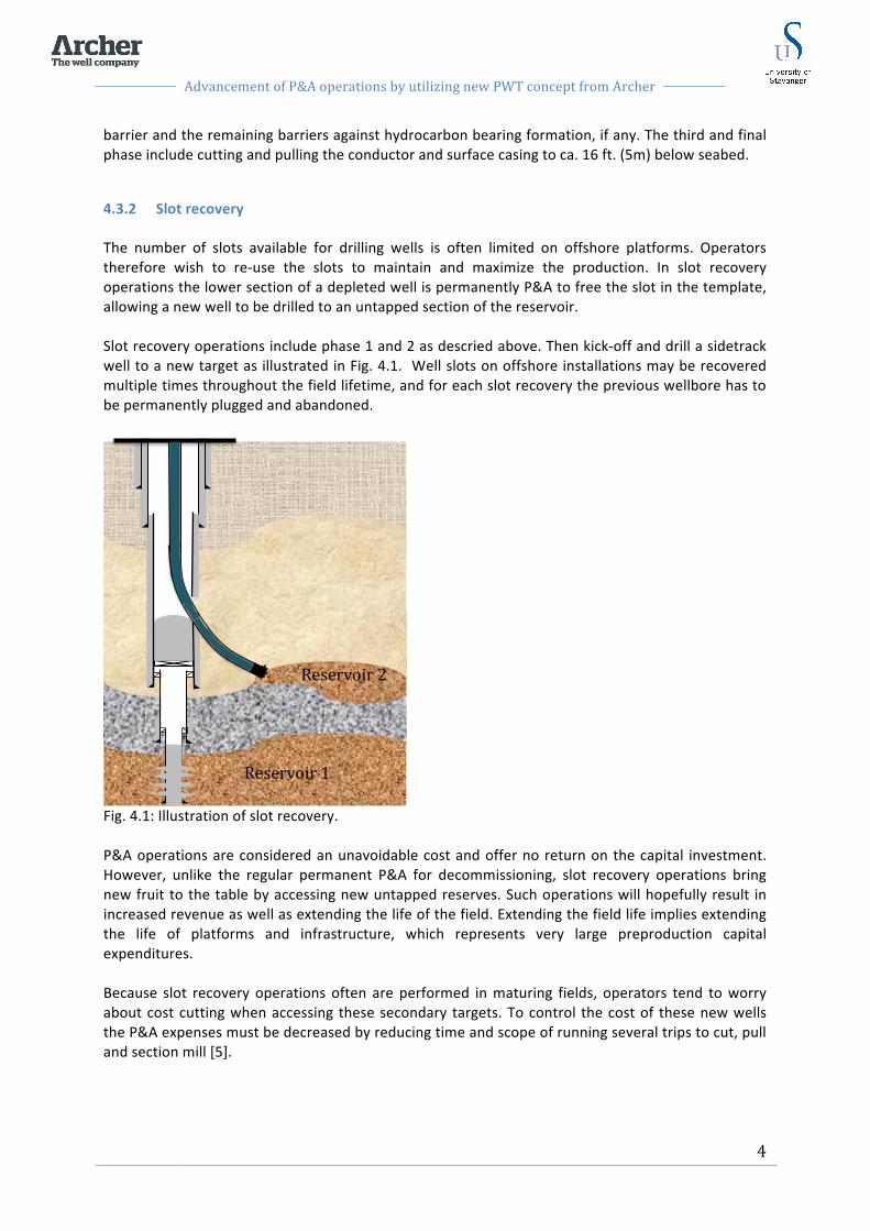
4.3.2 Slot recovery The number of slots available for drilling wells is often limited on offshore platforms. Operators therefore wish to re-‐use the slots to maintain and maximize the production. In slot recovery operations the lower section of a depleted well is permanently P&A to free the slot in the template, allowing a new well to be drilled to an untapped section of the reservoir. Slot recovery operations include phase 1 and 2 as descried above. Then kick-‐off and drill a sidetrack well to a new target as illustrated in Fig. 4.1. Well slots on offshore installations may be recovered multiple times throughout the field lifetime, and for each slot recovery the previous wellbore has to be permanently plugged and abandoned.
Fig. 4.1: Illustration of slot recovery. P&A operations are considered an unavoidable cost and offer no return on the capital investment. However, unlike the regular permanent P&A for decommissioning, slot recovery operations bring new fruit to the table by accessing new untapped reserves. Such operations will hopefully result in increased revenue as well as extending the life of the field. Extending the field life implies extending the life of platforms and infrastructure, which represents very large preproduction capital expenditures. Because slot recovery operations often are performed in maturing fields, operators tend to worry about cost cutting when accessing these secondary targets. To control the cost of these new wells the P&A expenses must be decreased by reducing time and scope of running several trips to cut, pull and section mill [5].
Reservoir 1
Reservoir 2

Advancement of P&A operations by utilizing new PWT concept from Archer
5
5 Rules and regulations
5.1 Governing authorities Any well operation on the NCS is governed by the The Activities Regulations issued by the Petroleum Safety Authority of Norway (PSA). The Activity Regulations states that NORSOK D-‐010 standard should be used as a minimum functional requirement for all well operations in Norway, including P&A operations [6]. The NORSOK standards are developed by the Norwegian petroleum industry to ensure adequate safety, value adding and cost effectiveness for the petroleum industry developments and operations.
5.2 Well integrity The term well integrity is defined in NORSOK D-‐010 as “an application of technical, operational and organizational solutions to reduce risk of uncontrolled release of formation fluids throughout the lifecycle of a well [7]. Well integrity includes having the barriers in place, understand and respect them, test and verify them, monitor and maintain them and have contingencies in place when or if the barriers fail during the life cycle of the well. The life cycle aspect includes the phases from design to after the well has been permanently plugged and abandoned, and all activities conducted in between [8]. For the P&A sequence, well integrity during and after P&A includes barrier material, barrier placement and subsequent monitoring of the well to detect potential leaks. The PSA facility regulation states; “ Well barriers shall be designed such that well integrity is ensured and the barrier functions are safeguarded during the wells lifetime. When a well is temporarily or permanently abandoned, the barriers shall be designed such that they take into account well integrity for the longest period of time the well is expected to be abandoned” [9]. Also, in addition to facility regulations, PSA activity regulations states; “All wells shall be secured before they are abandoned so that well integrity is safeguarded during the time they are abandoned” [10]. Well integrity is a complex topic and represents a challenge throughout the life cycle of the well. Problems may occur in different phases such as construction, production/ injection, intervention or the abandonment phase. During recent years more focus has been directed towards well integrity. A number of case studies have been performed to get an overview and display well integrity status on several fields. In 2006 PSA performed a well integrity survey on the NCS. The main findings of the survey revealed that 18% of the 406 wells tested had well integrity issues [11]. The identified issues were related to well barrier elements such as tubing, annulus safety valves, casing and cement because of corrosion, erosion, temperature effects and design issues. The survey confirms that well integrity is a consistent challenge and the industry needs to improve competence in well design, well barriers and quality control for equipment and the executed operations [12].
Advancement of P&A operations by utilizing new PWT concept from Archer
6
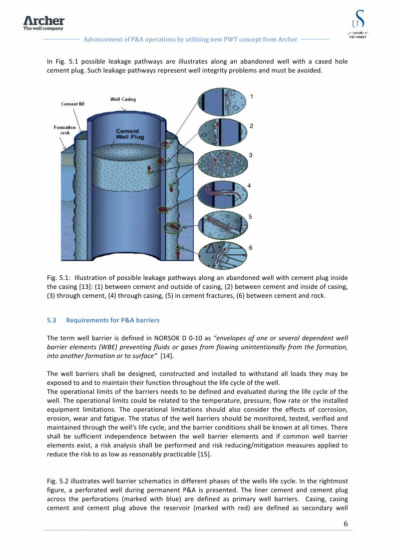
In Fig. 5.1 possible leakage pathways are illustrates along an abandoned well with a cased hole cement plug. Such leakage pathways represent well integrity problems and must be avoided.
Fig. 5.1: Illustration of possible leakage pathways along an abandoned well with cement plug inside the casing [13]: (1) between cement and outside of casing, (2) between cement and inside of casing, (3) through cement, (4) through casing, (5) in cement fractures, (6) between cement and rock.
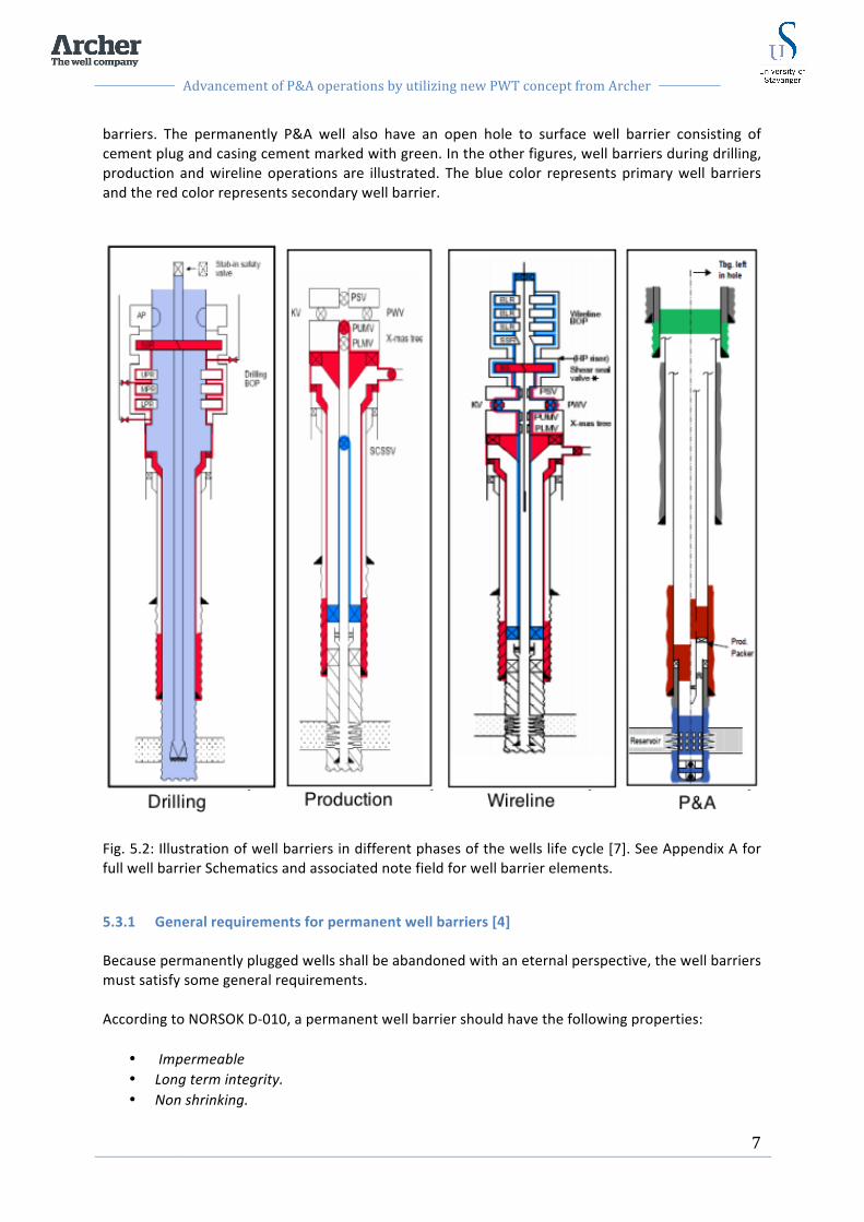
5.3 Requirements for P&A barriers The term well barrier is defined in NORSOK D 0-‐10 as “envelopes of one or several dependent well barrier elements (WBE) preventing fluids or gases from flowing unintentionally from the formation, into another formation or to surface” [14]. The well barriers shall be designed, constructed and installed to withstand all loads they may be exposed to and to maintain their function throughout the life cycle of the well. The operational limits of the barriers needs to be defined and evaluated during the life cycle of the well. The operational limits could be related to the temperature, pressure, flow rate or the installed equipment limitations. The operational limitations should also consider the effects of corrosion, erosion, wear and fatigue. The status of the well barriers should be monitored, tested, verified and maintained through the well‘s life cycle, and the barrier conditions shall be known at all times. There shall be sufficient independence between the well barrier elements and if common well barrier elements exist, a risk analysis shall be performed and risk reducing/mitigation measures applied to reduce the risk to as low as reasonably practicable [15]. Fig. 5.2 illustrates well barrier schematics in different phases of the wells life cycle. In the rightmost figure, a perforated well during permanent P&A is presented. The liner cement and cement plug across the perforations (marked with blue) are defined as primary well barriers. Casing, casing cement and cement plug above the reservoir (marked with red) are defined as secondary well
Advancement of P&A operations by utilizing new PWT concept from Archer
7
barriers. The permanently P&A well also have an open hole to surface well barrier consisting of cement plug and casing cement marked with green. In the other figures, well barriers during drilling, production and wireline operations are illustrated. The blue color represents primary well barriers and the red color represents secondary well barrier.
Fig. 5.2: Illustration of well barriers in different phases of the wells life cycle [7]. See Appendix A for full well barrier Schematics and associated note field for well barrier elements.
5.3.1 General requirements for permanent well barriers [4] Because permanently plugged wells shall be abandoned with an eternal perspective, the well barriers must satisfy some general requirements. According to NORSOK D-‐010, a permanent well barrier should have the following properties:
• Impermeable • Long term integrity. • Non shrinking.

Advancement of P&A operations by utilizing new PWT concept from Archer
8
• Ductile – (non brittle) – able to withstand mechanical loads/ impact. • Resistance to different chemicals/ substances (H2S, CO2 and hydrocarbons). • Wetting, to ensure bonding to steel.
Steel tubular is not an acceptable permanent WBE unless it is supported by cement, or a plugging material with similar functional properties as listed above, (inside and outside). Elastomer seals used as sealing components in WBEs are not acceptable for permanent well barriers. The presence and pressure integrity of casing cement shall be verified to assess the along hole pressure integrity of this WBE. The cement in annulus will not qualify as a WBE across the well (see illustration in Fig. 5.3). Open hole cement plugs can be used as a well barrier between reservoirs. It should, as far as practicably possible, also be used as a primary well barrier, see Table 24 attached in Appendix B. Cement in the liner lap, which has not been leak tested from above (before a possible liner top packer has been set) shall not be regarded a permanent WBE. Removal of downhole equipment is not required as long as the integrity of the well barriers is achieved. Control cables and lines shall be removed from areas where permanent well barriers are installed, since they may create vertical leak paths through the well barrier. When well completion tubulars are left in hole and permanent plugs are installed through and around the tubular, reliable methods and procedures to install and verify position of the plug inside the tubular and in the tubular annulus shall be established.
5.3.2 Barrier criteria To ensure that the barriers are robust enough to maintain an eternal perspective, there are four criteria required for the barriers to qualify as permanent.
-‐ Length -‐ Cross section -‐ Position -‐ Verification
5.3.2.1 Length The length of the cement plug must be adequate to ensure sufficient strength and capacity to handle the reservoir. Sufficient length is also crucial for the cement plug to be impermeable. Impermeable meaning that no fluid or gas should be able to flow through the material. The length requirement is based on if the cement plug has a foundation or not, and if the annulus casing cement function as barrier. According to NORSOK D-‐010 “the firm plug length shall be 328 ft. (100 m) MD. If a plug is set inside casing and with a mechanical plug as a foundation, the minimum length shall be 164 ft. (50m) MD.

Advancement of P&A operations by utilizing new PWT concept from Archer
9
The barriers shall extend minimum 164 ft. (50m) MD above any source of inflow/ leakage point. A plug in transition from open hole to casing should extend at least 164 ft. (50m) MD below casing shoe” [16].
5.3.2.2 Cross section Permanent well barriers shall according to NORSOK D-‐010 “extend across the full cross section of the well, include all annuli and seal both vertically and horizontally. Hence, a WBE set inside a casing, as part of a permanent well barrier, shall be located in a depth interval where there is a WBE with verified quality in all annuli.” Fig. 5.3 illustrates a well with a cement plug inside casing. The cement plug is sealing vertically inside the casing and sealing both horizontally and vertically in the casing-‐ formation annulus above the casing shoe.
Fig. 5.3: A permanent well barrier shall extend across the full cross section of the well, and seal both vertically and horizontally. [17]
5.3.2.3 Position The position of the barrier is crucial for its ability to function properly. The barrier must be positioned at a depth with sufficient formation integrity to prevent the formation rock from fracturing when exposed to pressure buildup. It is therefore important to know the minimum formation stress at the base of the barrier, and make sure the minimum formation stress is larger than the potential pressure buildup. It is also a NORSOK D-‐010 requirement to install the barrier as close as possible to the potential source of inflow, covering all possible leak paths.

Advancement of P&A operations by utilizing new PWT concept from Archer
10
5.3.2.4 Verification The operators must be sure that the well is in a desirable condition as the P&A operations progress. It is therefore a requirement to verify any barrier set in the well with respect to length, cross section, position and integrity. Type of barrier and the well condition will determine how the barrier can be tested. Logging, pressure testing, inflow testing, and load testing are some of the tests used for verification. This will be described further in sect. 6.4 and 6.5.
5.3.2.5 Number of barriers It is a general requirement that a well always holds two verified well barriers during all well activity. Every well is different and must be designed according to its well properties such as pressure, temperature and formation. The number of barriers needed to adequately permanently P&A a well will vary from each well. However, the NORSOK D-‐010 provides several requirements for sufficient plugging. When permanently plugging a well, two barriers shall be installed to seal off the reservoir zone, one primary barrier and one secondary barrier. In addition to the primary and secondary well barriers, an open hole to surface barrier is required to act as a final barrier against emissions. If the wellbore penetrate multiple reservoir zones or hydrocarbon bearing zones with different pressures, a primary and a secondary well barrier shall be installed for each reservoir zone as illustrated in Fig. 5.4.
Fig. 5.4: Multiple reservoirs plugged with two barriers against each reservoir and a open hole to surface plug.

Advancement of P&A operations by utilizing new PWT concept from Archer
11
However, if the formation consist of two reservoir zones within the same pressure regime, they can be regarded as one reservoir as illustrated in Fig. 5.5. In this case, both reservoirs can be isolated by two common well barriers.
Fig. 5.5: Two reservoir zones regarded as one reservoir due to similar reservoir pressure. [4]
Advancement of P&A operations by utilizing new PWT concept from Archer
12
6 Plugging wells
6.1 Plugging material The material used in a well barrier must meet the NORSOK D-‐010 requirements presented in sect. 5.3.2. Traditionally, cement has been the most used and best-‐qualified material for creating annular barriers and plugs all over the world. Cement is a well-‐known and field proven material to fit the purposes of P&A. However, over the last years, other materials and methods have been suggested including Sandaband, Thermaset or the use of formation as barrier. These will be briefly described below. The remaining theory will be based on cementing operations.
6.1.1 Sandaband Sandaband is a method developed to plug a wellbore with a specially designed sand slurry. The sand slurry consists of 75% particles of microsilicia, quartz and crushed rocks and 25% water or brine. It is essential for the sealing capacity of the slurry that the particles are of different size range. The smaller particles will then fill in the void space between the bigger particles to achieve complete isolation. The sand slurry is pumped into the wellbore with a mechanical plug as foundation, it can not be placed on a liquid base. The sand slurry does not set up after placement and does not shrink. It will not fracture when shear forces exceed its strength, but simply reshape along with the forces. Sandaband is a qualified method through laboratory testing and field testing and meets the requirements for permanent P&A barriers in NORSOK D-‐010 [18].
6.1.2 Thermaset [19] Thermaset is a polymer based resin that can be used as a permanent well barrier material. Thermaset are liquid polymers that will set when exposed to a predesigned temperature. Designed setting time depends on the time it is subjected to down hole temperature, and it will not set up unless subjected to the right temperature over a specific time. The setting time can vary from 15min to two days depending on the design. Thermaset is impermeable, bonds to steel, withstands high stress levels and it is ductile. Thermaset can be designed with a low viscosity which makes it possible to flow through narrow restrictions in the wellbore such as partly collapsed or deformed wells. Today there is limited field experience available for Thermaset compared to cement. However, according to the supplier, Thermaset is a good alternative to cement when permanently plugging a well for abandonment.
6.1.3 Formation as barrier It is a normal phenomenon that during drilling through certain formations, the rock moves inwards decreasing the diameter off the wellbore. This is usually considered undesirable since it can cause problems for drilling and running casing. However, in some situations this mechanism can be beneficial and create an annular barrier behind the casing. For formation to form an annular barrier the following requirements must be satisfied:

Advancement of P&A operations by utilizing new PWT concept from Archer
13
• The barrier formation must be shale since shale meets the barrier material requirements in NORSOK D-‐010.
• The strength of the shale must be sufficient to withstand the maximum expected pressure that could be applied to it. A leak off test must be performed to verify the formation strength.
• The displacement mechanism of the shale must be suitable to preserve the well barrier properties.
• The barrier must extend and seal over the full circumference of the casing and over a sufficient length along the well wellbore to meet the NORSOK D-‐010 requirements [20].
6.2 Cement [21] As mentioned above, cement is the traditional material used for barriers and plugs in wells. The cement may vary in complexity, but are usually based on Portland cement, known as a hydraulic cement. When hydraulic cement reacts chemically with water it will gradually set and harden. This reaction is called hydration and forms a stone-‐like solid mass. The hydration process starts as soon as the cement gets in contact with water. Therefore cement operators must carefully design the cement for its purpose depending on time, temperature and pressure conditions and composition and fineness of the cement formulations.
6.2.1 Squeeze cementing Squeeze cementing is a frequently used method to force or squeeze cement into a void space at a desired location in the well, by applying hydraulic pressure. Squeeze cementing operations may be performed during drilling, completion or P&A operations. Squeeze cementing is commonly used to [22]:
• Seal thief or lost-‐circulation zones • Repair casing leaks • Remedy a deficient primary cement job (for instance, incomplete coverage or under-‐
achieving top of cement) • Change the water/oil or gas/oil ratio by shutting off the breakthrough zone • Abandon a non-‐productive or depleted zone or the entire well • Modify injection profiles
The biggest challenge of squeeze cementing is placing the proper amount of cement in the correct location in the well. Depending on the remediation needed, squeeze cementing operations can be performed above the fracture gradient, high pressure squeeze, or below the fracture gradient, low pressure squeeze, of the exposed formation. Squeezing objective and zonal conditions determine whether high-‐ or low-‐ pressure methods are applied. Low pressure squeeze is the most frequently used method and usually implies higher accuracy for the placement and less cement used [22].

Advancement of P&A operations by utilizing new PWT concept from Archer
14
6.2.2 Balanced cement plug Setting cement plugs is an essential operation performed under several well conditions. Cement plugs are used for a variety of applications including lost circulation, zonal isolation, kick off and abandonment. A common method and simple technique to place a cement plug is the balanced plug method. The placement technique for a balanced plug is presented below. First a foundation must be placed in the well for the cement to be placed upon. The foundation can be a mechanical plug or a specially designed liquid base. To place the cement, a workstring with a cement assembly and cement stinger in the bottom-‐end is run down the hole to desired depth. The cement stinger is a tubular with smaller outside diameter than the tubular above. The balanced plug is then placed by pumping cement slurry through the workstring with a spacer fluid in front and behind. The spacer fluid cleans the pipe in front of the cement and displaces all previous liquids in the well. It prevents the cement from getting in contact with other fluids that might react with the cement and affect its designed properties. The spacer fluid however must be compatible with the cement and any other well fluid that might be downhole. As the spacerfluid with intermediate cement slurry hit the foundation, it is pushed up in the annulus between cement stinger and inner casing wall. As the height of cement in the annulus reaches the same height as the cement inside the stinger, a hydrostatic balance is created between them. The stinger will then be pulled out slowly to keep the fluids in balance and avoid mixing the fluids and damage the plug. When the stinger is pulled out it is important to give the cement plug sufficient time to set and harden to get a successful plug with desired properties. Previous experience has showed that effective cement plugs are a result of correct design and execution. In the design phase, well evaluation, written procedures, laboratory testing, spacer and slurry design must be thoroughly considered. During the execution phase, consideration must be given to contamination, mud and hole conditioning, cement volume and coordinating rig operations.
6.3 Cement plug quality [21], [23]. Whether you are constructing roads or constructing wells, good cementing practices are the key to structural integrity and controlling costs. Setting a cement plug right, the first time, is important for well performance and to avoid the high costs of subsequent plugs and remedial work. Even though plug-‐cementing operations have been regarded as relatively simple, history shows a significant failure rate. However, through years of field experience, development and stricter regulations, plug cementing has been considerably improved, but failures still occurs. The most common reasons for plug cement job failures include, interaction between the fluid system in the well and the plug cement slurry, insufficient prejob preparation, improper application of cementing practices, displacement practices and incorrect temperature. Cement plug volume and spacer fluid volume are vital to the success of the cement job. Insufficient spacer fluid volumes would probably result in incomplete mud removal due to poor cement/ mud separation. Insufficient cement volume due to incorrect estimation of borehole volumes would potentially result in a contaminated, weak cement plug of insufficient length. Contamination of the mud can reduce compressive strength of the cement by 70% in oil based mud systems. When calculating displacement volume, actual dimensions of drill-‐pipe should be used for best possible

Advancement of P&A operations by utilizing new PWT concept from Archer
15
results. The cement volume should be designed so the plug height does not exceed 700 ft. (ca. 213m), since the extra time taken to pull slowly out of the plug increase the risk of cementing-‐in the cement assembly. Also, impatience with set time and tagging the plug, can lead to incomplete setting of the cement plug and insufficient plugging.
6.4 Verification of cement plugs in wellbore As mentioned in section 5.3.2.4 all barriers placed in a well must be verified. NORSOK D-‐010 has several requirements for verification of cement plugs elaborated in table 24-‐ Cement plugs. Table 24-‐ Cement plug, is attached in APPENDIX B. According to table 24, the following requirements for plug verification in a well apply. “1. Cased hole plugs should be tested either in the direction of flow or from above. 2. The strength development of the cement slurry should be verified through observation of representative surface samples from the mixing cured under a representative temperature and pressure. 3. The plug installation shall be verified through documentation of job performance; records fm. cement operation (volumes pumped, returns during cementing, etc.). 4. Its position shall be verified” However, table 24 also states for cased hole cement plug; if a mechanical plug is used as a foundation for the cement plug and this is tagged and pressure tested the cement plug does not have to be verified.
6.4.1 Inflow test To verify that the cement plug is isolating in the direction of the flow, an inflow test can be performed. An inflow test is performed by reducing the hydrostatic pressure above the cement plug by bleeding off the shut in pressure or circulate to a lighter fluid. Pressure gauges are then monitored to see if pressure increase is observed in the well. If pressure increase is observed it indicates a leaking barrier and inflow of fluid or gas form the reservoir.
6.4.2 Pressure test To test the cement plug from above, a pressure test can be performed. This test is performed by pressuring the well up to a certain pressure. According to NORSOK D-‐010 a cased hole pressure test shall be 1000psi above estimated formation strength below the casing, or 500psi for surface casing plugs [Tabell 24]. Pressure gauges will then be carefully monitored to see if leaks in the plug or casing can be detected. If pressure is kept stable through the test period, no leaks are detected, and the plug is assumed to be good. The pressure test will reveal if there are leaks in the casing above the plug and insufficient cement coverage over the perforations, but it will not indicate the overall integrity of the entire cement plug.

Advancement of P&A operations by utilizing new PWT concept from Archer
16
6.4.3 Tag TOC and Load test [24] To verify the position of a cement plug top of cement (TOC) can be tagged. To tag TOC the work string or toolstring is slowly lowered until a reduction in weight is noticed as the string lands on the cement plug. Plug location and top of cement is then confirmed. To test integrity of the cement plug a load test can be performed. A load test is performed by lowering the toolstring onto the TOC similar to the tagging operation. Then the driller apply weight onto the string and observe the outcome. If the weight on bit (WOB) readings increase as more weight is applied, and the position of the bit is constant, the plug is solid, set and approved. On the other hand, if the string is allowed to sink into the cement plug as weight is applied, the cement plug is insufficient and of bad quality. It is normal that the uppermost and lowermost part of a cement plug might be of bad quality due to imperfection and contamination from mixing with other fluids. This poor quality cement may be referred to as rotten or green cement. In some wells the rotten cement on top of the cement plug is drilled off after the plug is set. This operation is referred to as “dress of” the cement plug. However, some times the operators are too eager to move on with the operation and do not give the cement enough time to set. Before concluding that a cement plug is of bad quality, operators should wait a few more hours before doing a new load test. It might be of good quality this time. Tag TOC and load test is often performed in the same operation. The driller first lowers the string to tag TOC followed by applying weight onto the cement plug to verify integrity.
6.5 Verification of annular cement -‐ Logging Logging is a widely used method to evaluate annular cement and several logging methods exist. Prior to a P&A operation the annular condition must be carefully evaluated to plan how the P&A operation should be performed. Bond and integrity of annular cement are two of the parameters that must be evaluated. For this purpose there are generally two main types of evaluation logging tools, Cement Bond Logs (CBL) and UltraSonic Image Tools (USIT) [25].
6.5.1 Cement Bond Log [26] Cement bond tools measure the bond between the casing and the annular cement and the bond between annular cement and formation. A transmitter is pulsed to send an omnidirectional acoustic signal. The signal travels through borehole fluid, pipe, cement and formation and is reflected back to a set of receivers on the tool. The tool then records the received signals and displays them on a log including the pipe-‐amplitude curve. Two measurements are evaluated to interpret the CBL log; measurement of cement-‐to-‐pipe bond, and measurement of cement-‐to-‐formation bond. The pipe amplitude curve is used to determine the quality of cement-‐to-‐ pipe bond. The amplitude is low in good-‐cemented casing and high in unsupported pipe. The waveform can be displayed as a Variable Density Log (VDL) where the positive and negative cycles of the waveform are shaded black and white respectively. The waveform determines both cement-‐to-‐pipe bond and cement-‐to-‐formation bond. Straight traces indicate no cement in borehole as illustrated in Fig. 6.2, while any variation in acoustic waveform indicate cement in the annular as illustrated in Fig. 6.1 and Fig. 6.2.
Advancement of P&A operations by utilizing new PWT concept from Archer
17
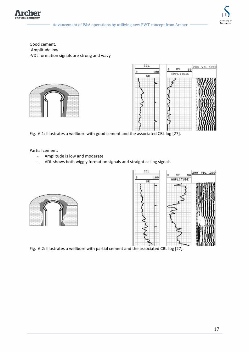
Good cement. -‐Amplitude low -‐VDL formation signals are strong and wavy
Fig. 6.1: Illustrates a wellbore with good cement and the associated CBL log [27]. Partial cement:
-‐ Amplitude is low and moderate -‐ VDL shows both wiggly formation signals and straight casing signals
Fig. 6.2: Illustrates a wellbore with partial cement and the associated CBL log [27].

Advancement of P&A operations by utilizing new PWT concept from Archer
18
No cement: -‐ High amplitude -‐ VDL straight, no formation signals. “V” type chevron patterns are seen at collars
Fig. 6.3: Illustrates a wellbore with no cement and the associated CBL log [27].
6.5.2 UltraSonic Image Tool [26] USIT is a ultrasonic scanning or imaging acoustic tool used to evaluate the casing condition and cement sheath in the annular space. Instead of a separate transmitter and receivers, the ultrasonic source and receivers are configured as a transducer. This ultrasonic transducer is rotated in the well while sending out ultrasonic signals. The ultrasonic signals will create resonance that will be detected by receivers. A log is recorded based on the signal frequency. Interpretation of the ultrasonic waveform makes it possible to determine casing radius, casing thickness and impedance of the material, which are in contact with both sides of the casing. The log is developed from the two wave travel time from transducer to casing, the frequency of the signal and the die down response of the signal. The results of the USIT are presented in image logs that provide visual presentation of cement quality. If cement is present behind the casing impedance will be high. And if no cement is present behind the casing impedance will be low. Unlike the CBL, USIT does not provide any information about the cement formation interface. It is therefore useful to use both CBL and ultrasonic logs for cement evaluation. A log example of free pipe and no annular cement is illustrated in Fig. 6.4. The log includes CBL and impedance image to the right. Light color on the impedance image combined with straight VDL and high amplitude indicates free pipe and no cement in annular.

Advancement of P&A operations by utilizing new PWT concept from Archer
19
Fig. 6.4: Illustration of USIT log in well with free pipe and no annular cement [27]. In Fig. 6.5 a log example of well cemented casing is illustrated. Dark colors on the impedance image combined with waved VDL and low amplitude indicates a well cemented casing and good cement in annular space.
Fig. 6.5: illustration of USIT log in well with well cemented casing [27].
6.5.3 Factors affecting log quality [28] Several factors affect the response of bond log tools. Some of these factors are micro annulus, non-‐centralized casing and non-‐centralized logging tool. A micro annulus is a very small annular gap between the casing and cement sheath of 0.01-‐0.1mm. If a micro annulus is present it can cause trouble for the CBL/VDL interpretation. The micro annulus may contain fluid or gas that will affect the interpretation of these logs. Non-‐centralized casing makes it difficult to interpret bond status behind the casing. The casing will then lean towards the formation wall and have little cement on the low side and a short distance between casing and formation. On the high side the distance will be longer and there might be a gap between the casing and the formation. Again this will damage the log interpretation.
Advancement of P&A operations by utilizing new PWT concept from Archer
20
Logging tool centralization is a crucial factor for the results of the logging. USIT and CBL tools must be centralized in the well for reliable log interpretation. Centralizers are used to keep the tool in center. However, an increased number of centralizers may prevent the tool from a smooth and even movement in the well. Uneven tool movement may create partial logging, which also affect the reliability of the logs.

Advancement of P&A operations by utilizing new PWT concept from Archer
21
7 Conventional methods for P&A The well barriers set to permanently plug a well must seal in all directions and establish complete isolation of the wellbore. If the primary cement around the casing is sufficient in the plugging area, and it can be verified, a cement plug with satisfying requirements can be placed inside the casing in the wellbore. This is referred to as a cased hole cement plug, and it is basically an easy operation.
7.1 Cut and pull However, satisfying primary cement behind the casing is rarely the case. The cement might be of bad quality and even absent in the plugging area. To accomplish full cross sectional barriers, the casing must then be removed. If the casing is free and loose, it can be cut at the required depth and pulled out. When the casing is out, a cement plug can be set with direct contact to the formation, a configuration often referred to as rock-‐to-‐rock, or open hole cement plug.
7.2 Section milling To cut and pull the casing to access the formation is always the first option. However, it is often impossible to pull out the desired casing due to various obstructions in the annulus. Old cement, settled particles and barite may be found in the annular, not allowing the casing to be pulled. If the casing cannot be pulled out, a more complex abandonment procedure must be performed. The need for a section milling operation applies. Section milling means to drill out a section of the casing. A milling assembly is then run into the well to the desired depth and cutting blades are extended by increasing the hydrostatic pressure. As rotation is initiated, the cutting blades cuts through the casing wall horizontally, before the driller lowers the milling assembly to mill out the casing section as illustrated in Fig. 7.1.
Fig. 7.1: Illustrates the milling principle. As the milling assembly is rotated and lowered, the cutting blades mill out the casing wall. After the millig operation is performed, the open hole section is washed to get rid of swarf and debris and the wellbore is circulated clean.

Advancement of P&A operations by utilizing new PWT concept from Archer
22
7.2.1 Challenges with section milling [29,30] The milling operation is complex and time consuming and possesses several challenges and uncertainties. Formation exposure, fluid properties, swarf handling and damaged well control equipment are some of the main considerations.
7.2.1.1 Open hole exposure Design of milling fluid is critical to perform a successful milling operation. As the mill removes the casing and annulus cement, it will be an open hole with direct contact to the formation. Milling fluids must therefore have sufficient weight to keep the open hole stable and proper viscosity to transport swarf and debris to the surface to achieve good hole cleaning. Swarf and debris released in the well will affect the viscous properties and pressure profile in the well. This might create Equivalent Circulation Densities (ECD) exceeding the fracture gradient of the open hole section which can cause fluid losses, swabbing, well control problems, poor hole cleaning and packing of cuttings in the wellbore leading to stuck pipe. Especially in reservoirs where the fracture pressure is close to the pore pressure milling can be difficult to perform.
7.2.1.2 Sufficient Hole cleaning If hole cleaning is bad, the swarf might gather in so called “bird nests”. This is steel slices of swarf twined and twisted together in a nest looking shape. Bird nest may accumulate where the velocity is reduced as in liner hanger, BOP and in the riser. Bird nest accumulation is undesirable and problematic. If bird nests form in the annular and ram BOP it can seriously affect the function and be a HSE risk. Therefore, the BOP must be washed and cleaned after every milling run with a washing tool. And when the milling operation is completed, the BOP should be opened, cleaned and inspected on the inside.
7.2.1.3 Low milling speed The milling speed is low, normally around 2-‐3m/hr and the weight on bit (WOB) must be adjusted not to exceed the appropriate weight. Low speed and WOB is necessary to achieve efficient hole cleaning and prevent large parts of the casing to be ripped off. Large parts of casing are hard to circulate out, and can easily get stuck in the well, causing trouble. Also if the WOB is too high, there is a risk that the mill can get jammed inside the casing. The rotation speed on the other hand must be quite high to mill effectively, and keep the size of swarf and debris small and easier to circulate out.
7.2.1.4 Rig vibrations When milling, the cutters of the mill assembly against the casing metal and casing cement creates continuous large vibrations in the pipe. These vibrations transfer to the derrick and rig and might release loose objects. To mitigate the risk of dropped objects, a so-‐called “Dropped Objects Management and Prevention (DROPS) check” must be performed in the derrick at least once a day. During a DROPS check, drilling personnel carefully inspect the derrick looking for potential hazards in loose objects.
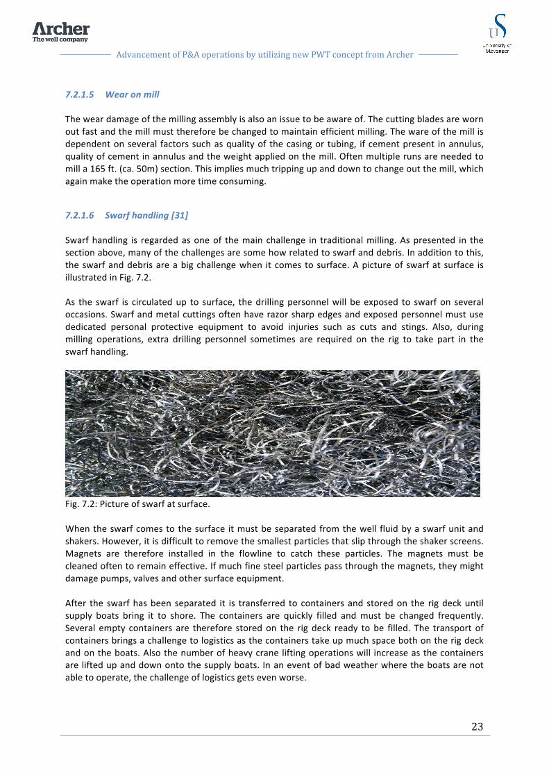
Advancement of P&A operations by utilizing new PWT concept from Archer
23
7.2.1.5 Wear on mill The wear damage of the milling assembly is also an issue to be aware of. The cutting blades are worn out fast and the mill must therefore be changed to maintain efficient milling. The ware of the mill is dependent on several factors such as quality of the casing or tubing, if cement present in annulus, quality of cement in annulus and the weight applied on the mill. Often multiple runs are needed to mill a 165 ft. (ca. 50m) section. This implies much tripping up and down to change out the mill, which again make the operation more time consuming.
7.2.1.6 Swarf handling [31] Swarf handling is regarded as one of the main challenge in traditional milling. As presented in the section above, many of the challenges are some how related to swarf and debris. In addition to this, the swarf and debris are a big challenge when it comes to surface. A picture of swarf at surface is illustrated in Fig. 7.2. As the swarf is circulated up to surface, the drilling personnel will be exposed to swarf on several occasions. Swarf and metal cuttings often have razor sharp edges and exposed personnel must use dedicated personal protective equipment to avoid injuries such as cuts and stings. Also, during milling operations, extra drilling personnel sometimes are required on the rig to take part in the swarf handling.
Fig. 7.2: Picture of swarf at surface. When the swarf comes to the surface it must be separated from the well fluid by a swarf unit and shakers. However, it is difficult to remove the smallest particles that slip through the shaker screens. Magnets are therefore installed in the flowline to catch these particles. The magnets must be cleaned often to remain effective. If much fine steel particles pass through the magnets, they might damage pumps, valves and other surface equipment. After the swarf has been separated it is transferred to containers and stored on the rig deck until supply boats bring it to shore. The containers are quickly filled and must be changed frequently. Several empty containers are therefore stored on the rig deck ready to be filled. The transport of containers brings a challenge to logistics as the containers take up much space both on the rig deck and on the boats. Also the number of heavy crane lifting operations will increase as the containers are lifted up and down onto the supply boats. In an event of bad weather where the boats are not able to operate, the challenge of logistics gets even worse.

Advancement of P&A operations by utilizing new PWT concept from Archer
24
7.3 Challenges with P&A and existing technologies The process of conventional P&A, including milling, is time consuming and costly and possess several challenges. The E&P companies are searching for new technology and methods to improve and simplify P&A and slot recovery operations. The overall goal for the petroleum industry is to make the P&A operation as cost effective as possible without compromising the quality. The industry is looking for new innovative and technical solutions to meet the challenges possessed by P&A operations. In addition to the challenges related to section milling described in sect. 7.2.1, the conventional P&A methods also faces challenges regarding quality, availability of rigs and information. These will be described briefly in the following section.
7.3.1 Removing casing As described in sect. 7.1, permanent P&A is conventionally performed by cutting and pulling the tubing and casing to access the formation, in order to place a cross-‐sectional barrier. The string may be stuck due to old cement and settled particles in the annulus. Time-‐consuming multiple cut and pull operations are then necessary to remove the casings. If still not able to cut and pull, the casing has traditionally been removed by section milling. As described in section 7.2.1, section milling possess several challenges and uncertainties and is time consuming and costly. It is undesirable, but up to recently, the only method to access the formation behind the casing for. Operators consider the section milling operation a challenge, and are eager to find alternatives to avoid section milling.
7.3.2 Quality of barriers As the purpose of P&A is to establish permanent barriers with eternal perspective the quality of the barriers is crucial. The P&A responsibility do not end with the P&A activities and not even with sale of the property. In an event of a failed seal, the operator is liable for the problem. In addition to the tremendous cost related to re entry and fixing leaking barriers, the E&P companies also have to consider the environmental damage and safety issues. It is therefore of great interests for the responsible part to do a sufficient P&A operation the first time.
7.3.3 Limited availability of rigs Traditionally P&A operations are performed by a rig due to the heavy work of pulling tubing and casing or section milling. However, using a rig to perform permanent P&A is very expensive and time consuming. In addition, with the high activity level, the drilling rig market is already in a position of shortage. Currently it is not possible to perform this kind of heavy operations without a rig. Operators are therefore looking for a way to set and verify permanent barriers in the well without the use of a rig.
7.3.4 Design the wells suitable for future P&A When designing new wells it should be kept in mind that eventually all wells shall be plugged and abandoned. Optimum well construction for future P&A would avoid several of the challenges present today if the initial well planning had incorporated other technology solutions.

Advancement of P&A operations by utilizing new PWT concept from Archer
25
7.3.5 Relevant documentation archived and available Many of the wells to be plugged on the NCS in the years to come was drilled over 30 years ago. Many of these wells do not have sufficient information regarding the well status and the life of the well in detail. Information and documentation regarding all parameters of the well is necessary to plan and perform a P&A operation. Extra work must therefore be executed to investigate and obtain the required well information. In addition to the challenges presented above, extended collaboration between companies and sharing of experience between drilling operators could benefit all parts on the P&A topic to move in the right direction.

Advancement of P&A operations by utilizing new PWT concept from Archer
26
8 The Perforate & Wash Tool To improve and streamline the P&A operation and avoid challenges with conventional methods, new technologies has been introduced to the market over the last years. One of these new technologies is the Perforate and Wash Tool by Archer. This PWT tool is designed to perforate a selected casing or liner sections where a cement plug is to be set. Then wash the perforated zone completely to clean out old cement and debris behind the casing. Following, cement is pumped down the tubing and through the perforations. By performing this method with the PWT tool, a permanent rock-‐to rock well barrier plug is established. The first edition of this PWT tool was introduced in 2009 and the first job was successfully conducted on the Ekofisk field in cooperation with ConocoPhillips. This edition of the tool included a three trip system and will be referred to as the 3 trip PWT method. The 3 trip method comprises three separate runs; perforating, washing and cementing. The first run include perforating a selected interval of the casing. The second trip is washing the annulus in the perforated section and the third trip include placement of a cement plug behind and above the perforated interval. Through further development of the PWT method, the three applications of the PWT tool were enabled in one single trip to improve efficiency of the operation and reduce tripping time. This method will be referred to as the PWT 1 trip method. The three steps described above, are now performed in the same run.; whereas the perforation gun is attached to the PWT string and disconnected after firing the guns. Then, the perforated interval is washed with the tools already in the string. After washing, the PWT tool is disconnected from the work string and left as a foundation for the cement plug. The work string is now solely open-‐ended pipe and the cement plug can be placed. The one trip method has also been field proven with good results. As the latest advancement of the PWT concept, a new technique has been developed to place cement in the perforated interval even more efficiently. This method will be referred to as the new PWT technique and is yet to be field proven as a world first. With the new PWT technique the perforation gun is run on wireline. Then, the perforated area is washed the same way as the PWT 1 trip and 3 trip. Instead of disconnecting the PWT tool, cement is pumped though the washing tool, enabling a good displacement and distribution of cement in the perforated interval. The standard sizes of the PWT design include 7”, 7 5/8”, 9 5/8”, 9 7/8”, 10 3/4”, 13 3/8” and 13 3/8”. However, other sizes are available on request. In the following chapter, these PWT methods will be presented in detail and operational sequences will be explained. As the 3 trip system has evolved to the 1 trip system and is no longer as relevant, the main focus will be on the 1 trip PWT method and the new PWT technique.
Fig. 8.1: Illustration of the PWT 1 trip tool. (Courtesy of Archer).
Advancement of P&A operations by utilizing new PWT concept from Archer
27
8.1 Planning phase A good and detailed planning phase is essential for a successful PWT operation. Each PWT job must be designed for the specific well where the job is to be performed. All phases of the job must be carefully evaluated and planned. Comprehensive operational procedures must be prepared and handed to the executing offshore personnel and a prejob meeting shall be performed offshore prior to any PWT job. In this meeting the details of the operation are presented to make sure all parties in the operation are cooperating and understanding the operation to be performed. The PWT plugging should preferably be performed in a section of the well where the casing was not cemented in a primary cement job. However, if the plug is to be set where primary cementing was performed, an evaluation of the annular cement is necessary to see if the PWT method is applicable. A certain amount of aged cement can be handled depending on the cement condition. Old and fractured cement could most likely be washed out without further difficulties. If primary cementing was not performed in the plugging area, there is most likely a fluid occupying the annular space. It is then important to know what type of fluid this is to be able to design a suitable washing fluid. Either way, if a primary cementing job was performed or not, the content of the annular must be known and evaluated through logging as described in sect. 6.5. It is also important that the log is relatively new due to potential alteration over time in the formation and annular in the plugging area. Formation strength in the plugging area must be known for several reasons. The cement plug barrier must be positioned at a depth with sufficient formation strength to prevent the formation rock from fracturing when exposed to pressure buildup over time. Minimum formation strength must be larger than the potential pressure buildup in the future. Also the formation strength must be evaluated to make sure pressure during the washing and cementing sequence do not fracture the formation in the plugging area. It is a fact that a great challenge in well operations is related to inner diameter (ID) and outer diameter (OD). Wellbore properties and casing sizes must be carefully evaluated to make sure the PWT tool is allowed to enter in the well at the correct setting depth.
8.1.1 Detailed Operation Procedure (DOP) Prior to the PWT plugging operation a Detailed Operation Procedure (DOP) is prepared. The DOP should consider all parameters affiliated with the operation such as well information, preparations for the operation, procedures, operation execution plan and after operation checklist. Well information include well data such as well pressures, temperatures, mud properties in the well and information about casing properties and depths. Technical limitations such as max running speed with the PWT in the well, max flow rates through PWT and specifications regarding inner diameter (ID) and outer diameter (OD) sizes is also included. Preparation for the operation include preparation checklists for all parties involved in the operation. The operator company is the responsible part and must prepare the overall plan. Contractor is responsible for running the equipment on drill floor. Contractor must prepare all the required
Advancement of P&A operations by utilizing new PWT concept from Archer
28
equipment such as top drive, iron roughneck and star racker and make sure to have suitable cross overs and kelly cocks in place and ready. Service companies are responsible for the cementing part of the operation and must prepare a cementing procedure including cement design. Archer oiltools will also have their own personnel offshore to follow up on the PWT tool and make sure the operation is performed according to the procedures. Procedures regarding the contractors and service companies standard operations are included in the DOP. This includes standard procedures for tripping in and out of the well, cementing procedures and procedure for the PWT operation. Operation execution plan is the detailed step-‐by-‐step plan to execute the PWT operation. Here all steps of the operation will be included such as PWT BHA preparation, tripping restrictions, how to adjust pump pressure and how to perform the perforate, wash and cement sequence with the PWT tool. After operation checklist include the after action review and evaluation of the PWT job. Here a checklist for all relevant experience should be registered, both positive and negative. This information is valuable for developing better procedures and take lesson learned to perform an even better job the next time. Also all test results from the operation and checklists for correct de-‐ mobilization of the equipment are included.
8.1.2 Fluid design Correct fluid design is essential for a successful PWT operation. All fluids circulated in and out of the annular space must be designed with respect to rheology and viscosity and density. The fluids must be compatible with each other to avoid intermixing and contamination of the cement resulting in a poor cement job and bad barrier. In addition the fluids must be adaptable for section milling, which is the contingency for the PWT operation.
8.1.2.1 Wash fluid The wash fluid is used to wash the annular space behind the perforated interval prior to placing the cement plug. An important application of the washing fluid is to minimize fluid losses. The wash fluid is in direct contact with the formation through the perforated casing. To minimize losses the washing fluid must contain some particles. The amount particles must be calculated to avoid bridging across the perforations. Bridging over the perforations is undesirable and could lead to blocked perforations, insufficient washing and a thick filtercake that could cause contamination of the cement. The particles in the wash fluid will contribute to increased ECD during washing. The ECD must be carefully monitored and adjusted by pumping pressure to not exceed the strength of the formation. If the ECD exceed the formation strength fluid losses will take place. In addition, the washing fluid must have sufficient viscosity to lift debris and dirt washed out from the annular up to surface.

Advancement of P&A operations by utilizing new PWT concept from Archer
29
8.1.2.2 Spacer fluid Spacer is pumped into the wellbore ahead of cement in order to clean and prepare the well for cement. The spacer fluid displaces the wash fluid to separate the cement from the wash fluid. Spacer fluid must be designed with proper rheology and density to completely fill up the annular space and all void spaces in the perforated section. Insufficient displacement of wash fluid may allow it to get in contact with the cement and cause contamination. Also the spacer must be designed with properties allowing it to be displaced by cement. Another important purpose of the spacer fluid is to completely water wet all surfaces to ensure sufficient cement to formation and cement to casing bonding. A standard water based spacer satisfying the properties described above has been used for the PWT operations performed.
8.1.2.3 Cement The cement is pumped behind the spacer fluid to establish the well barrier. Cement prepared for PWT plugging operations must be designed to fit the specific fields where it shall be applied. Appropriate cement additives must be added to handle gas migration and fluid loss. A relatively high fluid loss is desirable to hold squeeze pressure and dehydrate the cement against the formation, to form an impermeable barrier. However, fluid loss can not be too high due to potential accumulation of bridging across the perforations. Also for the cement, proper rheology is important for good displacement of the spacer. Another consideration for cement design is correct thickening time. Cement must be designed with appropriate thickening time to form a good barrier.
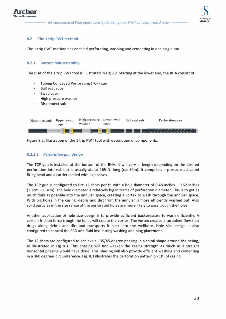
Advancement of P&A operations by utilizing new PWT concept from Archer
30
8.2 The 1 trip PWT method The 1 trip PWT method has enabled perforating, washing and cementing in one single run.
8.2.1 Bottom hole assembly The BHA of the 1 trip PWT tool is illustrated in Fig 8.2. Starting at the lower end, the BHA consist of:
-‐ Tubing Conveyed Perforating (TCP) gun -‐ Ball seat subs -‐ Swab cups -‐ High pressure washer -‐ Disconnect sub
Figure 8.2: Illustration of the 1 trip PWT tool with description of components.
8.2.1.1 Perforation gun design The TCP gun is installed at the bottom of the BHA. It will vary in length depending on the desired perforation interval, but is usually about 165 ft. long (ca. 50m). It comprises a pressure activated firing head and a carrier loaded with explosives. The TCP gun is configured to fire 12 shots per ft. with a hole diameter of 0.48 inches – 0.52 inches (1.2cm – 1.3cm). The hole diameter is relatively big in terms of perforation diameter. This is to get as much fluid as possible into the annular space, creating a vortex to wash through the annular space. With big holes in the casing, debris and dirt from the annular is more efficiently washed out. Also solid particles in the size range of the perforated holes are more likely to pass trough the holes. Another application of hole size design is to provide sufficient backpressure to wash efficiently. A certain friction force trough the holes will create the vortex. The vortex creates a turbulent flow that drags along debris and dirt and transports it back into the wellbore. Hole size design is also configured to control the ECD and fluid loss during washing and plug placement. The 12 shots are configured to achieve a 135/45-‐degree phasing in a spiral shape around the casing, as illustrated in Fig 8.3. This phasing will not weaken the casing strength as much as a straight horizontal phasing would have done. This phasing will also provide efficient washing and cementing in a 360 degrees circumference. Fig. 8.3 illustrates the perforation pattern on 1ft. of casing.
Ball seat sub Lower swab cups
Perforation gun High pressure washer
Upper swab cups
Disconnect sub
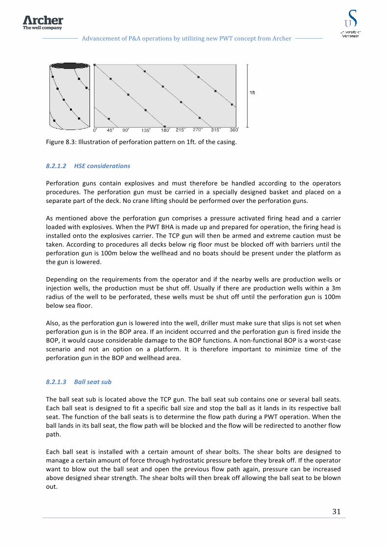
Advancement of P&A operations by utilizing new PWT concept from Archer
31
Figure 8.3: Illustration of perforation pattern on 1ft. of the casing.
8.2.1.2 HSE considerations Perforation guns contain explosives and must therefore be handled according to the operators procedures. The perforation gun must be carried in a specially designed basket and placed on a separate part of the deck. No crane lifting should be performed over the perforation guns. As mentioned above the perforation gun comprises a pressure activated firing head and a carrier loaded with explosives. When the PWT BHA is made up and prepared for operation, the firing head is installed onto the explosives carrier. The TCP gun will then be armed and extreme caution must be taken. According to procedures all decks below rig floor must be blocked off with barriers until the perforation gun is 100m below the wellhead and no boats should be present under the platform as the gun is lowered. Depending on the requirements from the operator and if the nearby wells are production wells or injection wells, the production must be shut off. Usually if there are production wells within a 3m radius of the well to be perforated, these wells must be shut off until the perforation gun is 100m below sea floor. Also, as the perforation gun is lowered into the well, driller must make sure that slips is not set when perforation gun is in the BOP area. If an incident occurred and the perforation gun is fired inside the BOP, it would cause considerable damage to the BOP functions. A non-‐functional BOP is a worst-‐case scenario and not an option on a platform. It is therefore important to minimize time of the perforation gun in the BOP and wellhead area.
8.2.1.3 Ball seat sub The ball seat sub is located above the TCP gun. The ball seat sub contains one or several ball seats. Each ball seat is designed to fit a specific ball size and stop the ball as it lands in its respective ball seat. The function of the ball seats is to determine the flow path during a PWT operation. When the ball lands in its ball seat, the flow path will be blocked and the flow will be redirected to another flow path. Each ball seat is installed with a certain amount of shear bolts. The shear bolts are designed to manage a certain amount of force through hydrostatic pressure before they break off. If the operator want to blow out the ball seat and open the previous flow path again, pressure can be increased above designed shear strength. The shear bolts will then break off allowing the ball seat to be blown out.

Advancement of P&A operations by utilizing new PWT concept from Archer
32
During the PWT operation a ball is dropped into the pipe from drill floor and forced down by pumping pressure. When the ball reaches its respective ball seat, the bypass flow trough the tool will be sealed off. The flow will then be directed through the outlet ports of the high-‐pressure washer. The tool is then in washing mode and pump pressure can be increased up to maximum loss free rate to wash out the annular space. On this tool, several ball seats can be installed. By installing several ball seats, the operator has opportunity to switch between bypass mode for circulation and washing mode, for as many times as they have ball seats. This configuration can be useful if some situation implies the need of circulation through the tool after washing is initiated. For example if much dirt and debris are generated form the washing job and starts to pack off in the well above the PWT tool a challenge arise. Since the flow is directed through the high pressure washer and through the perforations and annular space, the flow rate and lifting capacity is reduced. To solve this the ball seat directing the flow trough the high pressure washer can be blown out which again allow the flow to circulation through the PWT tool. The flow will then be as illustrated in Fig. 8.4.
1. Down the workstring and through the PWT tool
2. Out the bottom end of the tool and back into the tool in the flowport below the lower swab cup.
3. Through the tool and out the flowport above the upper swab cup.
Figure 8.4: Illustration of the flowpath in bypass circulation mode.
By circulation through the tool as described above, higher circulation rates are achieved which increase the lifting capacity of dirt and debris towards surface. Less pressure is then lost through the perforations and through the annular. When the dirt is circulated to surface, the ball seat can be blown out by increasing the pressure above the shear pressure of the ball seat, and a new ball can be dropped to initiate the washing sequence again.

Advancement of P&A operations by utilizing new PWT concept from Archer
33
8.2.1.4 Swab cups The swab cups are located under and above the outlet ports for the high pressure washer. The swab cups are designed to isolate and seal off a short section of the casing where washing is performed. A maximum pressure of 5000 psi (345 bar) can be applied between the cups. During the washing sequence the PWT tool is moved upwards and downwards. The isolated area will then undergo flushing at high fluid velocities to clean outer casing surface, annular space and formation wall. For best possible isolation, the outer diameters of the swab cups are slightly larger than the inner diameter of the casing. The rubber-‐like packer material of the swab cups allows them to get compressed and forced into slightly smaller tubing. When the PWT tool is run into the well, a bypass configuration allows well fluids to bypass the swab cups through channels inside the tool. The tool is then in tripping mode. This will avoid surge and swab effects created by the swab cups and allows a higher tripping speeds which save valuable rig time. The swab cups are fixed to the toolstring during the operation, but the distance between them can be adjusted prior to the operation for optimal performance. Fig. 8.5 illustrates three different options for the distance between upper and lower cups.
Figure 8.5: Three different options available for distance between swab cups. (Courtesy of Archer). The swab cups have two important functions during the PWT job. The first function is the one described above regarding sealing and isolation during washing. The second function is to create a mechanical foundation for the following cement plug. After the washing sequence, the PWT tool is positioned below the perforation interval and disconnected from the drill string. The swab cups together with the PWT tool will remain in its well position due to the friction of the swab cups against the inner casing wall. That way, the well is sealed off with a foundation and ready to receive cement to complete the plugging operation. A concern with the swab cups is the worn suffered from the sharp metal edges of the perforation holes while moving up and down during washing. However, the perforation hole size is designed to prevent damage to the cups. The casing steel around the perforation hole edge will receive a slight bend outwards as the perforation hole is forced through the steel. Due to this bend the cups will slide over the perforated holes with minimum amount of wear.
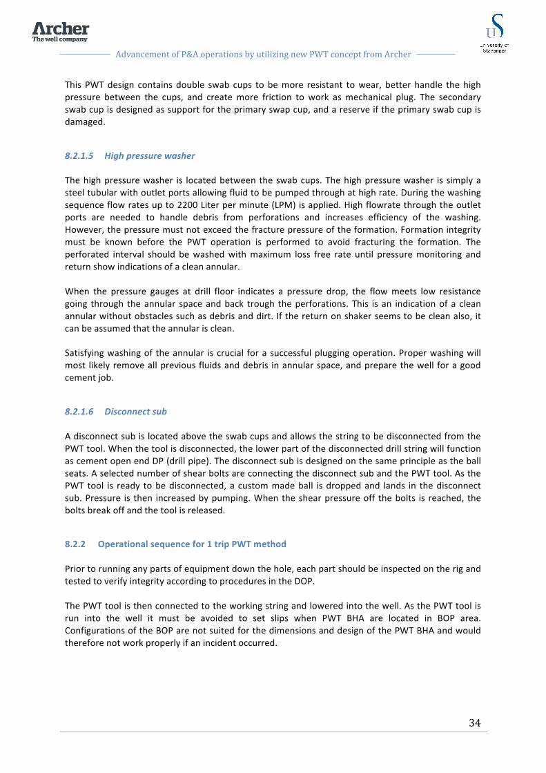
Advancement of P&A operations by utilizing new PWT concept from Archer
34
This PWT design contains double swab cups to be more resistant to wear, better handle the high pressure between the cups, and create more friction to work as mechanical plug. The secondary swab cup is designed as support for the primary swap cup, and a reserve if the primary swab cup is damaged.
8.2.1.5 High pressure washer The high pressure washer is located between the swab cups. The high pressure washer is simply a steel tubular with outlet ports allowing fluid to be pumped through at high rate. During the washing sequence flow rates up to 2200 Liter per minute (LPM) is applied. High flowrate through the outlet ports are needed to handle debris from perforations and increases efficiency of the washing. However, the pressure must not exceed the fracture pressure of the formation. Formation integrity must be known before the PWT operation is performed to avoid fracturing the formation. The perforated interval should be washed with maximum loss free rate until pressure monitoring and return show indications of a clean annular. When the pressure gauges at drill floor indicates a pressure drop, the flow meets low resistance going through the annular space and back trough the perforations. This is an indication of a clean annular without obstacles such as debris and dirt. If the return on shaker seems to be clean also, it can be assumed that the annular is clean. Satisfying washing of the annular is crucial for a successful plugging operation. Proper washing will most likely remove all previous fluids and debris in annular space, and prepare the well for a good cement job.
8.2.1.6 Disconnect sub A disconnect sub is located above the swab cups and allows the string to be disconnected from the PWT tool. When the tool is disconnected, the lower part of the disconnected drill string will function as cement open end DP (drill pipe). The disconnect sub is designed on the same principle as the ball seats. A selected number of shear bolts are connecting the disconnect sub and the PWT tool. As the PWT tool is ready to be disconnected, a custom made ball is dropped and lands in the disconnect sub. Pressure is then increased by pumping. When the shear pressure off the bolts is reached, the bolts break off and the tool is released.
8.2.2 Operational sequence for 1 trip PWT method Prior to running any parts of equipment down the hole, each part should be inspected on the rig and tested to verify integrity according to procedures in the DOP. The PWT tool is then connected to the working string and lowered into the well. As the PWT tool is run into the well it must be avoided to set slips when PWT BHA are located in BOP area. Configurations of the BOP are not suited for the dimensions and design of the PWT BHA and would therefore not work properly if an incident occurred.

Advancement of P&A operations by utilizing new PWT concept from Archer
35
8.2.2.1 Perforating While tripping into the well it is important to have good control of the depth of the PWT to make sure the plug is installed at the correct depth in the well. When the PWT tool is located at desired depth, the smallest ball is dropped into the pipe from drill floor. Pumping is initiated and the ball is forced down the pipe and landed in the ball catcher to fire off the perforation gun. All perforations are fired at the same time. The perforation gun being fired is illustrated in Fig. 8.6.
Figure 8.6: Illustration of the perforations being fired. (Courtesy of Archer). After the TCP gun has fired, it will automatically disconnected from the rest of the BHA and drop into the well. The well must have sufficient space below the perforated section to house the TCP gun. This free space may be referred to as a rat hole and must be able to house the TCP gun as well as the rest of the PWT tool. However, in a situation where the well do not allow the TCP gun and PWT to be dropped, it can be pulled out of hole (POOH) and disconnected at the rig floor.
8.2.2.2 Washing When the perforation sequence is completed the PWT is lowered to the upper area of the perforations. The next ball is dropped with a slightly larger size. As the ball is landed in its respective ball catcher, the fluid flow will be redirected from the bypass mode used for tripping, to washing mode. The flow is now directed through the outlet ports of the high pressure washer. Washing is initiated and fluid flow is increased in steps up to loss free rate of maximum 2200 Liters per minute, or 75% of shear value of the solid ball seat. In Fig. 8.7, the circulation path of the wash fluid is illustrated. Fluid will flow through the work string and out the ports of the high pressure washer between the swab cups. The flow continues through the perforations and into the annulus behind the casing. Dirt, debris, and previous fluid behind the casing will be cleaned out and carried upwards in the annular. The flow will then pass through the

Advancement of P&A operations by utilizing new PWT concept from Archer
36
upper perforations, above the upper swab cups and back into the wellbore inside the casing, before it is circulated towards the surface.
Figure 8.7: Illustrates four steps of the washing sequence. (1) Illustrates the tool in position to start washing the perforations. (2) Illustrates initiation of washing. (3) Illustrates tool being lowered to wash out next section. (4) Illustrates the final part of washing. (Courtesy of Archer). When pumping is initiated the pressure readings at the surface will be high and unstable due to blocked perforations and dirt in the annular space. As the perforations are forced open by high velocity washing flow and dirt from the annular is washed out, flow resistance through the perforations and annulus decreases. The pressure readings at surface will then decrease and stabilize. When the pressure readings are stable the section in the annulus between the swab cups can be assumed to be clean. The PWT tool is then slowly lowered, moving the swab cups to the next section to be washed. As illustrated in Fig. 8.7 the PWT is first run down towards the bottom perforations. When it reaches the bottom the process is reversed and washing is repeated upwards. The washing process is continued until pressure data and return on shakers indicates a clean annular. Washing time will vary depending on the content in the annular space and how quickly the annular allows to be cleaned. Larger amounts of settled particles, barite, old cement and dirt may require longer washing time. When the annular space is assumed to be clean the washing sequence is stopped. The PWT tool is then placed with the upper swab cups below the perforated interval, in position to function as a mechanical foundation for the upcoming cement plug. A deactivation ball is dropped to disconnection of the PWT tool from the work string. As the ball lands in its ball catcher and pressure is increased, the disconnect sub will release the PWT tool. Due to the friction force of the swab cups against the inner casing wall, the tool will be held in place and manage the weight of the cement to be placed on top.
1 2 3 4
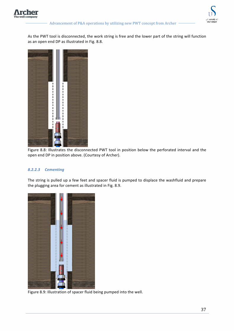
Advancement of P&A operations by utilizing new PWT concept from Archer
37
As the PWT tool is disconnected, the work string is free and the lower part of the string will function as an open end DP as illustrated in Fig. 8.8.
Figure 8.8: Illustrates the disconnected PWT tool in position below the perforated interval and the open end DP in position above. (Courtesy of Archer).
8.2.2.3 Cementing The string is pulled up a few feet and spacer fluid is pumped to displace the washfluid and prepare the plugging area for cement as illustrated in Fig. 8.9.
Figure 8.9: Illustration of spacer fluid being pumped into the well.
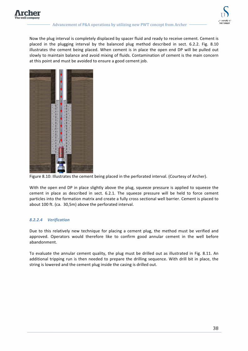
Advancement of P&A operations by utilizing new PWT concept from Archer
38
Now the plug interval is completely displaced by spacer fluid and ready to receive cement. Cement is placed in the plugging interval by the balanced plug method described in sect. 6.2.2. Fig. 8.10 illustrates the cement being placed. When cement is in place the open end DP will be pulled out slowly to maintain balance and avoid mixing of fluids. Contamination of cement is the main concern at this point and must be avoided to ensure a good cement job.
Figure 8.10: Illustrates the cement being placed in the perforated interval. (Courtesy of Archer). With the open end DP in place slightly above the plug, squeeze pressure is applied to squeeze the cement in place as described in sect. 6.2.1. The squeeze pressure will be held to force cement particles into the formation matrix and create a fully cross sectional well barrier. Cement is placed to about 100 ft. (ca. 30,5m) above the perforated interval.
8.2.2.4 Verification Due to this relatively new technique for placing a cement plug, the method must be verified and approved. Operators would therefore like to confirm good annular cement in the well before abandonment. To evaluate the annular cement quality, the plug must be drilled out as illustrated in Fig. 8.11. An additional tripping run is then needed to prepare the drilling sequence. With drill bit in place, the string is lowered and the cement plug inside the casing is drilled out.

Advancement of P&A operations by utilizing new PWT concept from Archer
39
Figure 8.11: Illustration of the cement being drilled out to be able to evaluate the annular cement by logging. (Courtesy of Archer). When a plug is set in a section milled window, it can be difficult to drill through it afterword’s for verification purposes. The cement plug is likely to be harder than the formation, resulting in the drill bit to slip off and sidetrack into the formation. However, in this situation with cement inside a perforated casing, the inner casing walls will support the drillbit and guide it downwards. The cement plug is now drilled out and the hole is circulated clean. Logging is then performed as described in sect. 6.5. The cemented section is logged with CBL and USIT logs to evaluate the new annular cement. The logging tools are prepared and run through the plugging interval as illustrated in Fig. 8.12. The new log is then compared to existing post-‐ logs for comparison of annular sealing ability of the cement.
Figure 8.12: Illustration of the logging tool being run to evaluate the annular cement and the log. (Courtesy of Archer).

Advancement of P&A operations by utilizing new PWT concept from Archer
40
In the future it will not be necessary to drill out and re-‐ log the plug interval to verity the annular cement. As the method has been sufficiently field proven, it will be qualified as a standard method. More time will then be saved from additional tripping, drilling and logging.
8.2.2.5 Completing cement job and test plug When the new logs are evaluated and annular cement is approved, the work string with cement open end is RIH and the cement procedure is repeated. Cement will be placed to about 100 ft. (ca. 30,5 m) above the perforated interval for better isolation and increased impermeability. When the plug is in place the cement need time to set and harden. The wait on cement (WOC) time will depend on the cement design for each job. However, an average time of 16-‐24 hours can be expected. The final cement plug is now in place as illustrated in Fig. 8.13, and ready to be tested. The work string with open end used to place cement is kept in the hole when waiting for the cement to be set. The open end DP can then be used to tag TOC as described in sect. 6.4.3. A pressure test should also be performed to test integrity of the plug as described in sect. 6.4.2.
Figure 8.13: Illustrates the final cement plug being placed. (Courtesy of Archer).

Advancement of P&A operations by utilizing new PWT concept from Archer
41
8.3 The New technique for PWT operation The new PWT method introduces an improved technique for placing cement in the perforated interval. By utilizing this technique the whole plugging operation is performed more efficiently and potentially with higher quality. With the new PWT method the perforation gun is run on wireline and fired off prior to washing and cementing with the PWT tool. After washing sequence is completed, the PWT tool is not disconnected from the work string. Spacer fluid and cement is placed into the perforated interval through the flow port of the high pressure washer, between the swab cups. The swab cups will then have the same function as during the washing sequence. A short section of the wellbore is isolated between the cups and allows spacer and then cement to be placed trough the perforations and into the annular space. When placing cement, pump pressure is increased to create a squeeze function in order to force cement into the annular and fill up the annular space completely. As the cement is being pumped, the tool is pulled up slowly. Cement will then completely fill up the perforated interval to establish a full cross sectional cement barrier. As mentioned above the PWT tool will not be disconnected during the plugging sequence, and can therefore not be used as foundation for the cement plug. A mechanical plug or a fluid base must therefore be placed in the well prior to the PWT operation. It would therefore be undesirable to drop the perforation gun on top of the mechanical plug or into the fluid base.
8.3.1 Bottom hole assembly The BHA design is similar as the one used for PWT 1 trip. However, with the new technique, the TCP gun is run on wireline and therefore not included in the main workstring. The PWT BHA for the new technique is illustrated in Fig. 8.14 and will include:
-‐ Ball seat sub -‐ Swab cups -‐ High pressure washer
Figure 8.14: Illustration of the BHA design for the new PWT technique with description of components. The above-‐mentioned BHA components are identical to the ones explained for the 1 trip system. The ball seat sub, swab cups and high pressure washer are presented in sections 8.2.1.3, 8.2.1.4 and 8.2.1.5 respectively. A configuration that will vary for each PWT job is the amount of ball seats the operator choose to install. As described in sect. 8.2.1.3, the ball seats can switch the flow from bypass mode to washing mode and vice versa by blowing out the previous ball seat and drop a new ball into the pipe.
Ball seat sub Lower swab cups
Upper swab cups
High pressure washer
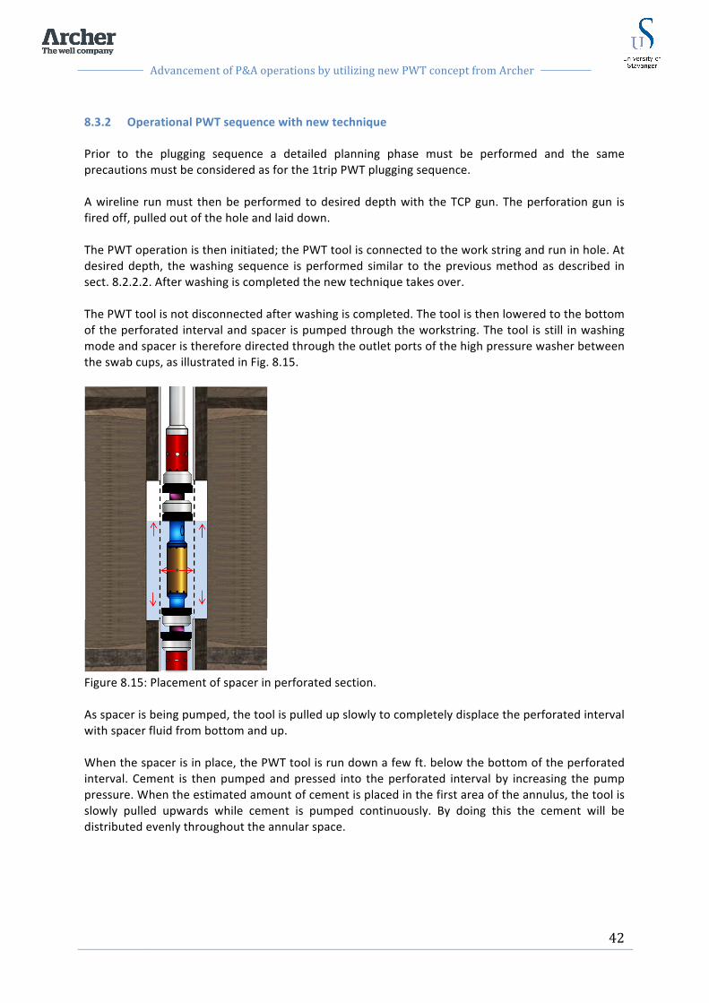
Advancement of P&A operations by utilizing new PWT concept from Archer
42
8.3.2 Operational PWT sequence with new technique Prior to the plugging sequence a detailed planning phase must be performed and the same precautions must be considered as for the 1trip PWT plugging sequence. A wireline run must then be performed to desired depth with the TCP gun. The perforation gun is fired off, pulled out of the hole and laid down. The PWT operation is then initiated; the PWT tool is connected to the work string and run in hole. At desired depth, the washing sequence is performed similar to the previous method as described in sect. 8.2.2.2. After washing is completed the new technique takes over. The PWT tool is not disconnected after washing is completed. The tool is then lowered to the bottom of the perforated interval and spacer is pumped through the workstring. The tool is still in washing mode and spacer is therefore directed through the outlet ports of the high pressure washer between the swab cups, as illustrated in Fig. 8.15.
Figure 8.15: Placement of spacer in perforated section. As spacer is being pumped, the tool is pulled up slowly to completely displace the perforated interval with spacer fluid from bottom and up. When the spacer is in place, the PWT tool is run down a few ft. below the bottom of the perforated interval. Cement is then pumped and pressed into the perforated interval by increasing the pump pressure. When the estimated amount of cement is placed in the first area of the annulus, the tool is slowly pulled upwards while cement is pumped continuously. By doing this the cement will be distributed evenly throughout the annular space.

Advancement of P&A operations by utilizing new PWT concept from Archer
43
The flow path of the cement being pumped into the annulus is illustrated in Fig. 8.16. The flow path will be as follows:
1. Down the workstring and through the ports of the high pressure washer. 2. Through the perforations and into the annular space. The annular space will be filled up from
the bottom and the spacer will be displaced upwards. 3. Through the upper perforations and back into the wellbore. Due to the open perforations
above the upper swab cup, excess cement will flow back into the cased hole and into four open ports on the red component on the illustration in Fig. 8.16, above the upper swab cup. Cement will flow through the flow port of the red component and down through a bypass channel in the tool and through an outlet in the bottom end of the tool. This way the excess cement will be circulated through the tool and complete the cross sectional barrier in the wellbore.
Figure 8.16: Placement of cement through high pressure washer. When the cups are pulled up above the perforated interval, the isolated area between the swab cups will be inside blank casing without perforations. A pressure increase will then be noticed at drill floor that indicates the position of the tool above the perforated interval. Cement pumping is then stopped. In order to switch the flow from going through high pressure washer, and into bypass flow pressure is increased to blow out the ball seat. As the shear pressure of the ball seat is reached it will break off. Additional cement is then directed through the bypass ports and out the lower end of the tool. The additional cement is placed to about 100 ft. (30,5m) above the perforations. The perforated interval is now completely cemented as illustrated in Fig. 8.17. A cross sectional barrier is now in place that meets the requirements of NORSOK D-‐010 [4]. The plug must then be verified by tagging TOC and pressure tested once the cement plug has built sufficient compressive strength.

Advancement of P&A operations by utilizing new PWT concept from Archer
44
Figure 8.17: Illustration of the well with cement plug in place after PWT operation.
PWT tool pulled out after plug in place
100 ft. (ca.30,5m) excess cement on top of perforated interval
165 ft. (ca.50m) cement plug in perforated interval
Base fluid or mechanical plug as foundation for cement plug

Advancement of P&A operations by utilizing new PWT concept from Archer
45
9 Case study This case study will compare the traditional P&A method of section milling with the PWT concept. Four cases will be presented and compared with respect to time and scope. All operational steps are presented in a time planner. The data used in this case study are based on typical well data from an Ekofisk well. However, due to restrictions regarding publishing these data, platforms and well names will not be mentioned. The case study will compare section milling, PWT (3trip), PWT (1trip) and the new technique for PWT operations. Something special about the Ekofisk field is the Miocene gas zone at about 6500 ft. depth. This Miocene zone holds higher than normal gas levels and can cause trouble during drilling operations. When P&A operations are performed on the Ekofisk field, this zone has to be plugged with two barriers in addition to the reservoir barriers. This case study will include the operation of placing two Miocene barriers to seal off the Miocene zone for permanent P&A. Prior to the two Miocene plugs, two reservoir barriers have been placed to seal off the reservoir zone. In addition, an open hole to surface barrier must be installed after the Miocene plugs are in place to complete the P&A operation. For this case study it is assumed that the PWT technique and also the new PWT technique are approved as standard methods. The plugs set by the PWT method will therefor not be drilled out in order to log the annulus for verification. However, the cement plugs must be verified by traditional tests including tag TOC, load tests and pressure tests. It is important to mention that there are always uncertainties related to well operations. When a well is entered to perform an operation, incidents may occur that require sudden changes in the primary plan. Most well operations are carefully planned in detail, but as unexpected events occur during the operation the plan must be adjusted. The operational steps presented in this case are based on operations performed according to the plan with no unexpected events.
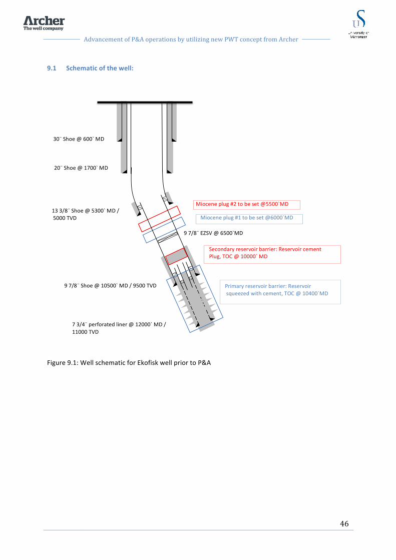
Advancement of P&A operations by utilizing new PWT concept from Archer
46
9.1 Schematic of the well:
Figure 9.1: Well schematic for Ekofisk well prior to P&A
13 3/8¨ Shoe @ 5300` MD / 5000 TVD
30¨ Shoe @ 600` MD
20¨ Shoe @ 1700` MD
9 7/8¨ Shoe @ 10500` MD / 9500 TVD
7 3/4¨ perforated liner @ 12000` MD / 11000 TVD
Miocene plug #1 to be set @6000`MD
Miocene plug #2 to be set @5500`MD
9 7/8¨ EZSV @ 6500`MD
Primary reservoir barrier: Reservoir squeezed with cement, TOC @ 10400`MD
Secondary reservoir barrier: Reservoir cement Plug, TOC @ 10000` MD
Advancement of P&A operations by utilizing new PWT concept from Archer
47
9.2 Case: Set Miocene plug #1 and #2 in 9 7/8 in. casing The two plugs are to be set in an Ekofisk production well. Production was recently stopped and the well has been prepared for P&A. As a primary reservoir barrier, the reservoir has been squeezed with cement up to the production packer at 10400 ft. MD as illustrated in Fig. 9.1. As secondary reservoir barrier a 165 ft. (ca. 50m) cement plug has been placed inside the 9 7/8 in. casing where cement evaluation logs revealed sufficient annular cement sealing. The secondary reservoir barrier is illustrated in Fig. 9.1. Cement evaluation logs were run in the plugging area of the Miocene plugs. Interpretation of the logs revealed a small amount of solids particles and old cement. A cased holed cement barrier is not an option in this area because it will not meet the NORSOK D-‐010 requirements of a cross sectional well barrier. Other options must therefore be evaluated and performed to place a permanent well barrier in the 9 7/8 in. casing section. These other options are presented below as section milling, PWT (3trip), PWT (1 trip) and the new technique for PWT operations. All depths referred to in this case study are Rotary Kelly Bushing (RKB) depths from a platform rig.
9.2.1 Objective Set Miocene plug #1 and #2.
-‐ Miocene plug #1: Set 165 ft. (ca. 50m) cement plug in 9 7/8 in. casing at 6000 ft. (1828,8m) MD.
-‐ Miocene plug #2: Set 165 ft. (ca. 50m) cement plug in 9 7/8 in. casing at 5500 ft. (1676,4m) MD.
9.2.2 Current well status
-‐ Prepared for P&A -‐ Temporary plugs removed -‐ Production tubing cut and pulled -‐ Reservoir squeezed with cement as primary barrier TOC 10400 ft. (3169,92m) MD. -‐ Cement evaluation logs performed in 9 7/8 in. casing revealed good annular cement from 9
7/8 in. shoe at 10500 ft. (3200,4m) MD to 9500 ft. (2895,6m) MD. -‐ 165 ft. cement plug placed as secondary reservoir barrier at TOC 10000 ft. (3048m) MD. -‐ EZSV plug placed in 9 7/8 in. casing at 6500 ft. (1981,2m) MD. The EZSV plug has been tagged
and verified.

Advancement of P&A operations by utilizing new PWT concept from Archer
48
9.2.3 Case assumptions
-‐ No obstacles in the wellbore that prevent entering 9 7/8 in. casing or other areas of the wellbore.
-‐ Assume that the time to wait on cement to set is equal for all cases. WOC time is 20h. -‐ Assume that good final tests (Load test, pressure test) are performed for the cement plugs in
all cases. -‐ All operation procedures are performed as planned without technical or operational issues. -‐ No well control problems.

Advancement of P&A operations by utilizing new PWT concept from Archer
49
9.3 Solution #1: Section milling As described in Ch. 7, the conventional method to perform a P&A operation include section milling and placement of a balanced cement plug. In the following chapter this conventional method will be applied to place the two Miocene plugs.
9.3.1 Planned operation Miocene plug #1:
-‐ Section mill a window for Miocene plug #1 of 165 ft.(ca. 50m) between 5835 ft. (1778,5 m) MD and 6000 ft. (1828,8m) MD.
-‐ Set a balanced cementing plug to place a cross sectional barrier in the milled window.
Miocene plug #2: -‐ Section mill a window for Miocene plug #2 of 165 ft. (ca. 50m) between 5335 ft. (1626,1m)
MD and 5500 ft. (1676,4 m) MD. -‐ Set a balanced cement plug to place a cross sectional barrier in the milled window.
9.3.2 Assumptions for the operation
-‐ Tripping speed with mill ca. 1000 ft/hr (ca. 305m/h) -‐ Mill rate, rate of penetration (ROP) at average 8 ft/h (ca. 2.5m/h). Low ROP must be applied
through the connections of 2 ft. (ca. 0.6m) and maximum 12 ft/h (ca. 3.7m/h) can be applied through tubing.
-‐ The mill will constantly wear during milling depending on several factors such as casing quality, annular cement and WOB. It is assumed that the mill must be changed two times during the milling operation. One time during milling of the window for Miocene plug #1, and one time prior to milling window for Miocene plug #2.
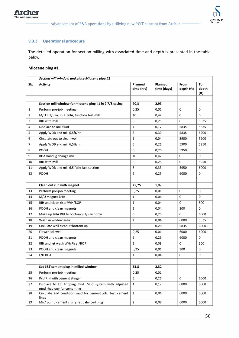
Advancement of P&A operations by utilizing new PWT concept from Archer
50
9.3.3 Operational procedure The detailed operation for section milling with associated time and depth is presented in the table below. Miocene plug #1 Section mill window and place Miocene plug #1
Stp Activity Planned time (hrs)
Planned time (days)
From depth (ft)
To depth (ft)
Section mill window for miocene plug #1 in 9 7/8 casing 70,3 2,93
1 Perform pre-‐job meeting 0,25 0,01 0 0
2 M/U 9 7/8 in. mill BHA, function test mill 10 0,42 0 0
3 RIH with mill 6 0,25 0 5835
4 Displace to mill fluid 4 0,17 5835 5835
5 Apply WOB and mill 6,5ft/hr 8 0,33 5835 5900
6 Circulate out to clean well 1 0,04 5900 5900
7 Apply WOB and mill 6,5ft/hr 5 0,21 5900 5950
8 POOH 6 0,25 5950 0
9 BHA handlig change mill 10 0,42 0 0
10 RIH with mill 6 0,25 0 5950
11 Apply WOB and mill 6,5 ft/hr last section 8 0,33 5950 6000
12 POOH 6 0,25 6000 0
Clean out run with magnet 25,75 1,07
13 Perform pre-‐job meeting 0,25 0,01 0 0
14 M/U magnet BHA 1 0,04 0 0
15 RIH and clean riser/WH/BOP 1 0,04 0 300
16 POOH and clean magnets 1 0,04 300 0
17 Make up BHA RIH to bottom 9 7/8 window 6 0,25 0 6000
18 Wash in wndow area 1 0,04 6000 5835
19 Circulate well clean 2*bottom up 6 0,25 5835 6000
20 Flowcheck well 0,25 0,01 6000 6000
21 POOH and clean magnets 6 0,25 6000 0
22 RIH and jet wash WH/Riser/BOP 2 0,08 0 300
23 POOH and clean magnets 0,25 0,01 300 0
24 L/D BHA 1 0,04 0 0
Set 165`cement plug in milled window 55,8 2,32
25 Perform pre-‐job meeting 0,25 0,01
26 P/U RIH with cement stinger 6 0,25 0 6000
27 Displace to KCl tripping mud. Mud system with adjusted mud rheology for cementing
4 0,17 6000 6000
28 Circulate and condition mud for cement job. Test cement lines
1 0,04 6000 6000
29 Mix/ pump cement slurry set balanced plug 2 0,08 6000 6000

Advancement of P&A operations by utilizing new PWT concept from Archer
51
30 Pull above estimated TOC at 5835 ft MD 1 0,04 6000 5835
31 Drop DP wiper balls and circulate to clean pipe 0,5 0,02 5835 5835
32 WOC 20 0,83 5835 5835
33 Tag TOC and pressure test 1 0,04 5835 5835
34 POOH 6 0,25 5835 0
35 M/U and RIH clean out assembly 2 0,08 0 5835
36 Wash down, dress off, Load test plug 6 0,25 5835 5835
37 POOH 6 0,25 5835 0
Total time for Miocene plug #1 151,75 6,32
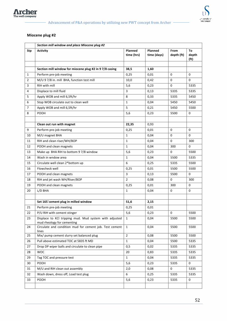
Advancement of P&A operations by utilizing new PWT concept from Archer
52
Miocene plug #2 Section mill window and place Miocene plug #2
Stp Activity Planned time (hrs)
Planned time (days)
From depth (ft)
To depth (ft)
Section mill window for miocene plug #2 in 9 7/8 casing 38,5 1,60
1 Perform pre-‐job meeting 0,25 0,01 0 0
2 M/U 9 7/8 in. mill BHA, function test mill 10,0 0,42 0 0
3 RIH with mill 5,6 0,23 0 5335
4 Displace to mill fluid 3 0,13 5335 5335
5 Apply WOB and mill 6,5ft/hr 8 0,33 5335 5450
6 Stop WOB circulate out to clean well 1 0,04 5450 5450
7 Apply WOB and mill 6,5ft/hr 5 0,21 5450 5500
8 POOH 5,6 0,23 5500 0
Clean out run with magnet 22,35 0,93
9 Perform pre-‐job meeting 0,25 0,01 0 0
10 M/U magnet BHA 1 0,04 0 0
11 RIH and clean riser/WH/BOP 1 0,04 0 300
12 POOH and clean magnets 1 0,04 300 0
13 Make up BHA RIH to bottom 9 7/8 window 5,6 0,23 0 5500
14 Wash in wndow area 1 0,04 5500 5335
15 Circulate well clean 2*bottom up 6 0,25 5335 5500
16 Flowcheck well 0,25 0,01 5500 5500
17 POOH and clean magnets 3 0,13 5500 0
18 RIH and jet wash WH/Riser/BOP 2 0,08 0 300
19 POOH and clean magnets 0,25 0,01 300 0
20 L/D BHA 1 0,04 0 0
Set 165`cement plug in milled window 51,6 2,15
21 Perform pre-‐job meeting 0,25 0,01
22 P/U RIH with cement stinger 5,6 0,23 0 5500
23 Displace to KCl tripping mud. Mud system with adjusted mud rheology for cementing
1 0,04 5500 5500
24 Circulate and condition mud for cement job. Test cement lines
1 0,04 5500 5500
25 Mix/ pump cement slurry set balanced plug 2 0,08 5500 5500
26 Pull above estimated TOC at 5835 ft MD 1 0,04 5500 5335
27 Drop DP wiper balls and circulate to clean pipe 0,5 0,02 5335 5335
28 WOC 20 0,83 5335 5335
29 Tag TOC and pressure test 1 0,04 5335 5335
30 POOH 5,6 0,23 5335 0
31 M/U and RIH clean out assembly 2,0 0,08 0 5335
32 Wash down, dress off, Load test plug 6 0,25 5335 5335
33 POOH 5,6 0,23 5335 0

Advancement of P&A operations by utilizing new PWT concept from Archer
53
Total time for Miocene plug #2 112,4 4,68
Total time for Miocene plug #1 and #2 with section milling 264,1 11,00

Advancement of P&A operations by utilizing new PWT concept from Archer
54
9.3.4 Well barrier schematic after milling and cement job
Figure 9.2: Well barrier schematic for section milled well.
30¨ Shoe @ 600` MD
20¨ Shoe @ 1700` MD
13 3/8¨ Shoe @ 5300` MD / 5000 TVD
9 7/8¨ Shoe @ 10500` MD / 9500 TVD
7 3/4¨ perforated liner @ 12000` MD / 11000 TVD
Miocene plug #1 set @6000` MD in section milled window
Miocene plug #2 set @5500` MD in section milled window
9 7/8¨ EZSV @ 6500`MD
Primary reservoir barrier: Reservoir squeezed with cement, TOC @ 10400`MD
Secondary reservoir barrier: Reservoir cement Plug, TOC @ 10000` MD

Advancement of P&A operations by utilizing new PWT concept from Archer
55
9.4 Solution #2: Perf & Wash (3trip) As mentioned in the introduction the first PWT technique included a three-‐trip sequence to perforate, wash and place the cement plug. In the following chapter this initial PWT technique will be applied to place the two Miocene plugs.
9.4.1 Planned operation Miocene plug #1:
-‐ Trip 1: Perforate a 165 ft. (ca. 50m) interval with a TCP gun at 6000 ft. (1828,8m) MD. -‐ Trip 2: Wash through the perforated area with the PWT tool and clean out the well. -‐ Trip 3: Enter with a cement stinger and place a 165 ft. (ca. 50m) balanced cement plug
Miocene plug #2:
-‐ Trip 1: Perforate a 165 ft. (ca. 50m) interval with a TCP gun at 5500 ft. (1676,4m) MD. -‐ Trip 2: Wash through the perforated area with the PWT tool and clean out the well. -‐ Trip 3: Enter with a cement stinger and place a 165 ft. (ca. 50m) balanced cement plug
9.4.2 Assumptions
-‐ Tripping speed with the PWT tool is limited to 700 ft/hr -‐ Washing speed 6,5 ft/hr (ca. 2m/hr). -‐ Washing time about 12hrs. The washing time will generally depend on each well and how
fast the annular space allows to be cleaned. -‐ PWT tool used as foundation for cement plug.

Advancement of P&A operations by utilizing new PWT concept from Archer
56
9.4.3 Operational procedure The detailed operation for PWT 3 trip with associated time and depth is presented in the table below. Miocene plug #1 Set Miocene plug #1 with Perf&wash (3 trip)
Stp Activity Planned time(hrs)
Planned time(days)
From depth (ft)
To depth (ft)
Trip 1 perforate 20,8 0,86
1 Perform pre-‐job meeting 0,25 0,01 0 0
2 M/U 165ft. perforation gun 2 0,08 0 0
3 RIH with perforation gun 6 0,25 0 6000
4 Break pipe drop ball and pressure up to fire off perf gun 1,25 0,05 6000 6000
5 Flow check well 0,25 0,01 6000 6000
6 Circulate out well 5 0,21 6000 6000
7 POOH and lay down guns 6 0,25 6000 0
Trip 2 wash 28,2 1,17
8 P/U PWT BHA 2 0,08 0 0
9 RIH with PWT 6 0,25 0 6000
10 Break pipe drop ball to initiate washing 0,5 0,02 6000 6000
11 Test swab cups 0,15 0,01 6000 6000
12 Wash perforations from bottom up 12 0,50 6000 5835
13 RIH and place PWT below perforations 0,25 0,01 6010 6010
14 Break pipe drop ball to release PWT 1 0,04 6010 6010
15 Pressure up to blow out ball seat, PWT released 0,25 0,01 6010 6010
16 POOH 6 0,25 6010 0
Trip 3 cement 43,0 1,79
17 P/U cement stinger 1 0,04 0 0
18 RIH with cement stinger 6 0,25 6000 6000
19 Displace with spacer 1,5 0,06 6000 6000
20 Displace to KCl tripping mud. Mud system with adjusted mud rheology for cementing
3 0,13 6000 6000
21 Circulate and condition mud for cement job. Test cement lines
1 0,04 6000 6000
22 Mix/ pump cement slurry set cement plug 2 0,08 6000 6000
23 Pull above estimated TOC at 5830 ft MD 1 0,04 6000 5830
24 Drop DP wiper balls and circulate to clean pipe 0,5 0,02 5830 5830
25 Squeeze cement, hold squeeze, WOC 20 0,83 5830 5830
26 Tag TOC and test plug 1 0,04 5830 5830
27 POOH 6,0 0,25 5830 0
Total time for Miocene plug #1 91,9 3,83
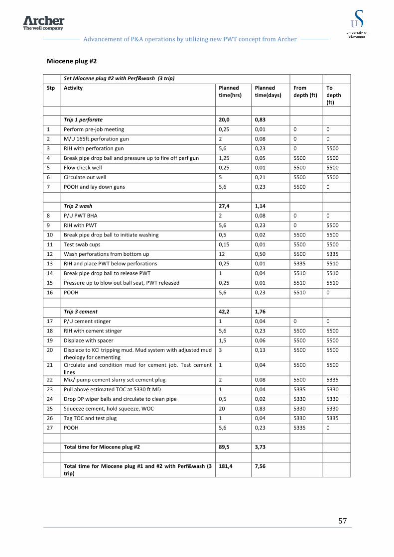
Advancement of P&A operations by utilizing new PWT concept from Archer
57
Miocene plug #2 Set Miocene plug #2 with Perf&wash (3 trip)
Stp Activity Planned time(hrs)
Planned time(days)
From depth (ft)
To depth (ft)
Trip 1 perforate 20,0 0,83
1 Perform pre-‐job meeting 0,25 0,01 0 0
2 M/U 165ft.perforation gun 2 0,08 0 0
3 RIH with perforation gun 5,6 0,23 0 5500
4 Break pipe drop ball and pressure up to fire off perf gun 1,25 0,05 5500 5500
5 Flow check well 0,25 0,01 5500 5500
6 Circulate out well 5 0,21 5500 5500
7 POOH and lay down guns 5,6 0,23 5500 0
Trip 2 wash 27,4 1,14
8 P/U PWT BHA 2 0,08 0 0
9 RIH with PWT 5,6 0,23 0 5500
10 Break pipe drop ball to initiate washing 0,5 0,02 5500 5500
11 Test swab cups 0,15 0,01 5500 5500
12 Wash perforations from bottom up 12 0,50 5500 5335
13 RIH and place PWT below perforations 0,25 0,01 5335 5510
14 Break pipe drop ball to release PWT 1 0,04 5510 5510
15 Pressure up to blow out ball seat, PWT released 0,25 0,01 5510 5510
16 POOH 5,6 0,23 5510 0
Trip 3 cement 42,2 1,76
17 P/U cement stinger 1 0,04 0 0
18 RIH with cement stinger 5,6 0,23 5500 5500
19 Displace with spacer 1,5 0,06 5500 5500
20 Displace to KCl tripping mud. Mud system with adjusted mud rheology for cementing
3 0,13 5500 5500
21 Circulate and condition mud for cement job. Test cement lines
1 0,04 5500 5500
22 Mix/ pump cement slurry set cement plug 2 0,08 5500 5335
23 Pull above estimated TOC at 5330 ft MD 1 0,04 5335 5330
24 Drop DP wiper balls and circulate to clean pipe 0,5 0,02 5330 5330
25 Squeeze cement, hold squeeze, WOC 20 0,83 5330 5330
26 Tag TOC and test plug 1 0,04 5330 5335
27 POOH 5,6 0,23 5335 0
Total time for Miocene plug #2 89,5 3,73
Total time for Miocene plug #1 and #2 with Perf&wash (3 trip)
181,4 7,56

Advancement of P&A operations by utilizing new PWT concept from Archer
58
9.5 Solution #3: Perf & Wash (1trip) As described in the introduction to Ch.8, the three trip PWT method was further developed to a one trip PWT method. By including the whole PWT sequence in one single trip, more efficient P&A operations was achieved due to less time spent on tripping and BHA handling. In the following chapter this one trip PWT technique will be applied to place the two Miocene plugs.
9.5.1 Planned operation Miocene plug #1:
-‐ Perforate the casing with TCP gun at 6000 ft. (1828,8m) MD, wash the perforated area and clean well, then place a 165 ft. (ca. 50m) cement plug in the well during one trip.
Miocene plug #2:
-‐ Perforate the casing with TCP gun at 5500 ft. (1676,4), wash the perforated area and clean well, then place a 165 ft. (ca. 50m) cement plug in the well during one trip.
9.5.2 Assumptions
-‐ Tripping speed with the PWT tool is limited to 700 ft/hr -‐ Washing speed 6,5 ft/hr (ca. 2m/hr). -‐ Washing time about 12hrs. The washing time will depend on each well and how fast the
annular space allows to be cleaned. -‐ PWT tool used as foundation for cement plug

Advancement of P&A operations by utilizing new PWT concept from Archer
59
9.5.3 Operational procedure The detailed operation for PWT 1 trip with associated time and depth is presented in the table below. Miocene plug #1 Set Miocene plug #1 with Perf&wash (1 trip)
Stp Activity Planned time(hrs)
Planned time(days)
From depth (ft)
To depth (ft)
Perforate, wash and cement in one trip 63,8 2,66
1 Perform pre-‐job meeting 0,25 0,01 0 0
2 M/U PWT with TCP gun 2 0,08 0 0
3 RIH with PWT and TCP gun 6 0,25 0 6000
4 Break pipe drop ball and pressure up to fire off perf gun
1,25 0,05 6000 6000
5 Flow check well 0,25 0,01 6000 6000
6 Circulate and clean well 5 0,21 6000 6000
7 Break pipe drop ball to initiate washing 0,5 0,02 6000 6000
8 Test swab cups 0,25 0,01 6000 6000
9 Washing 12 0,50 6000 5835
10 RIH and place PWT below perforations 0,25 0,01 5835 6010
11 Break pipe drop ball to release PWT 1 0,04 6010 6010
12 Pressure up to blow out ball seat 0,25 0,01 6010 6010
13 When PWT released POOH 7 ft 0,15 0,01 6010 6003
14 Pump spacer 1,5 0,06 6003 6003
15 When spacer fluid pumped RIH to bottom perf 0,15 0,01 6010 6010
16 R/U cement lines and test lines 1 0,04 6010 6010
17 Mix/ pump cement slurry set balanced plug 2 0,08 6010 6010
18 R/D cement lines. Drop DP wiper balls and circ pipe clean
3 0,13 6010 5830
19 Squeeze cement, hold squeeze, WOC 20 0,83 5830 5830
20 Tag TOC and test plug 1 0,04 5830 5830
21 POOH 6 0,25 5830 0
Total time for Miocene plug #1 63,8 2,66

Advancement of P&A operations by utilizing new PWT concept from Archer
60
Miocene plug #2 Set Miocene plug #2 with Perf&wash (1 trip)
Stp Activity Planned time(hrs)
Planned time(days)
From depth (ft)
To depth (ft)
Perforate, wash and cement in one trip 63,0 2,63
1 Perform pre-‐job meeting 0,25 0,01 0 0
2 M/U PWT with TCP gun 2 0,08 0 0
3 RIH with PWT and TCP gun 5,6 0,23 0 5500
4 Break pipe drop ball and pressure up to fire off perf gun
1,25 0,05 5500 5500
5 Flow check well 0,25 0,01 5500 5500
6 Circulate and clean well 5 0,21 5500 5500
7 Break pipe drop ball to initiate washing 0,5 0,02 5500 5500
8 Test swab cups 0,25 0,01 5500 5500
9 Washing 12 0,50 5500 5335
10 RIH and place PWT below perforations 0,25 0,01 5335 5530
11 Break pipe drop ball to release PWT 1 0,04 5530 5530
12 Pressure up to blow out ball seat 0,25 0,01 5530 5530
13 When PWT released POOH 7 ft 0,15 0,01 5530 5523
14 Pump spacer 1,5 0,06 5523 5335
15 When spacer fluid pumped RIH to bottom perf 0,15 0,01 5335 5500
16 R/U cement lines and test lines 1 0,04 5500 5500
17 Mix/ pump cement slurry set balanced plug 2 0,08 5500 5235
18 R/D cement lines. Drop DP wiper balls and circ pipe clean
3 0,13 5235 5235
19 Squeeze cement, hold squeeze, WOC 20 0,83 5235 5235
20 Tag TOC and test plug 1 0,04 5235 5235
21 POOH 5,6 0,23 5235 0
Total time for Miocene plug #2 63,0 2,63
Total time for Miocene plug #1 and #2 with Perf&wash (1trip)
126,8 5,28

Advancement of P&A operations by utilizing new PWT concept from Archer
61
9.5.4 Well barrier schematic after PWT job is performed
Figure 9.3: Well barrier schematic after PWT operation is performed.
30¨ Shoe @ 600` MD
20¨ Shoe @ 1700` MD
13 3/8¨ Shoe @ 5300` MD / 5000 TVD
9 7/8¨ Shoe @ 10500` MD / 9500 TVD
7 3/4¨ perforated liner @ 12000` MD / 11000 TVD
Miocene plug #1 set @6000`MD by PWT method
Miocene plug #2 set @5500`MD by PWT method
9 7/8¨ EZSV @ 6500`MD
Primary reservoir barrier: Reservoir squeezed with cement, TOC @ 10400`MD
Secondary reservoir barrier: Reservoir cement Plug, TOC @ 10000` MD

Advancement of P&A operations by utilizing new PWT concept from Archer
62
9.6 Solution #4: Perf & Wash with new technique As described in Ch.9 the new technique for PWT operations has been developed for an even more efficient PWT operation. In the following chapter the new PWT technique will be applied to place the two Miocene plugs.
9.6.1 Planned operation Miocene plug # 1:
-‐ Perforate 165 ft. interval in 9 7/8 in. casing with wireline at 6000 ft. (1828,8m) MD -‐ Wash and place a 165 ft. cement plug in the well with the new PWT technique.
Miocene plug #2:
-‐ Perforate 165 ft. interval in 9 7/8 in. casing with wireline at 5500 ft. (1676,4m) MD -‐ Wash and place a 165 ft. cement plug in the well with the new PWT technique.
9.6.2 Assumptions
-‐ Tripping speed with the PWT tool is limited to 700 ft/hr -‐ Washing speed 6,5 ft/hr (ca. 2m/hr). -‐ Washing time about 12hrs. The washing time will depend on each well and how fast the
annular space allows to be cleaned. -‐ EZSV plug set as plug foundation -‐ Since EZSV plug is set as foundation the cement plug does not have to be verified, see
appendix B,Table 24.
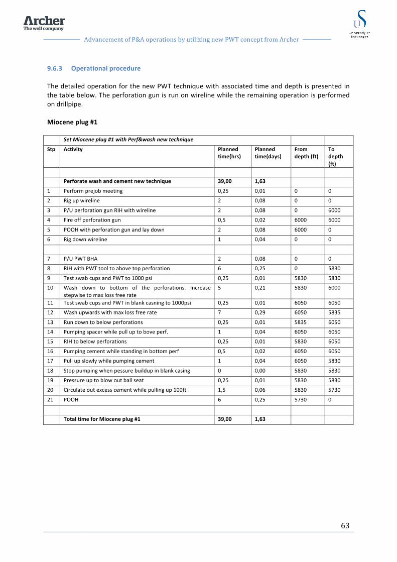
Advancement of P&A operations by utilizing new PWT concept from Archer
63
9.6.3 Operational procedure The detailed operation for the new PWT technique with associated time and depth is presented in the table below. The perforation gun is run on wireline while the remaining operation is performed on drillpipe. Miocene plug #1 Set Miocene plug #1 with Perf&wash new technique
Stp Activity Planned time(hrs)
Planned time(days)
From depth (ft)
To depth (ft)
Perforate wash and cement new technique 39,00 1,63
1 Perform prejob meeting 0,25 0,01 0 0
2 Rig up wireline 2 0,08 0 0
3 P/U perforation gun RIH with wireline 2 0,08 0 6000
4 Fire off perforation gun 0,5 0,02 6000 6000
5 POOH with perforation gun and lay down 2 0,08 6000 0
6 Rig down wireline 1 0,04 0 0
7 P/U PWT BHA 2 0,08 0 0
8 RIH with PWT tool to above top perforation 6 0,25 0 5830
9 Test swab cups and PWT to 1000 psi 0,25 0,01 5830 5830
10 Wash down to bottom of the perforations. Increase stepwise to max loss free rate
5 0,21 5830 6000
11 Test swab cups and PWT in blank casning to 1000psi 0,25 0,01 6050 6050
12 Wash upwards with max loss free rate 7 0,29 6050 5835
13 Run down to below perforations 0,25 0,01 5835 6050
14 Pumping spacer while pull up to bove perf. 1 0,04 6050 6050
15 RIH to below perforations 0,25 0,01 5830 6050
16 Pumping cement while standing in bottom perf 0,5 0,02 6050 6050
17 Pull up slowly while pumping cement 1 0,04 6050 5830
18 Stop pumping when pessure buildup in blank casing 0 0,00 5830 5830
19 Pressure up to blow out ball seat 0,25 0,01 5830 5830
20 Circulate out excess cement while pulling up 100ft 1,5 0,06 5830 5730
21 POOH 6 0,25 5730 0
Total time for Miocene plug #1 39,00 1,63
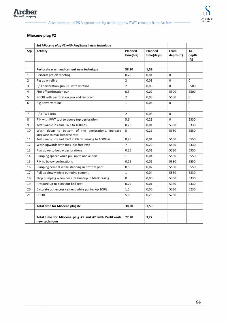
Advancement of P&A operations by utilizing new PWT concept from Archer
64
Miocene plug #2 Set Miocene plug #2 with Perf&wash new technique
Stp Activity Planned time(hrs)
Planned time(days)
From depth (ft)
To depth (ft)
Perforate wash and cement new technique 38,20 1,59
1 Perform prejob meeting 0,25 0,01 0 0
2 Rig up wireline 2 0,08 0 0
3 P/U perforation gun RIH with wireline 2 0,08 0 5500
4 Fire off perforation gun 0,5 0,02 5500 5500
5 POOH with perforation gun and lay down 2 0,08 5500 0
6 Rig down wireline 1 0,04 0 0
7 P/U PWT BHA 2 0,08 0 0
8 RIH with PWT tool to above top perforation 5,6 0,23 0 5330
9 Test swab cups and PWT to 1000 psi 0,25 0,01 5330 5330
10 Wash down to bottom of the perforations. Increase stepwise to max loss free rate
5 0,21 5330 5550
11 Test swab cups and PWT in blank casning to 1000psi 0,25 0,01 5550 5550
12 Wash upwards with max loss free rate 7 0,29 5550 5330
13 Run down to below perforations 0,25 0,01 5330 5550
14 Pumping spacer while pull up to above perf. 1 0,04 5550 5550
15 RIH to below perforations 0,25 0,01 5330 5550
16 Pumping cement while standing in bottom perf 0,5 0,02 5550 5550
17 Pull up slowly while pumping cement 1 0,04 5550 5330
18 Stop pumping when pessure buildup in blank casing 0 0,00 5330 5330
19 Pressure up to blow out ball seat 0,25 0,01 5330 5330
20 Circulate out excess cement while pulling up 100ft 1,5 0,06 5330 5230
21 POOH 5,6 0,23 5230 0
Total time for Miocene plug #2 38,20 1,59
Total time for Miocene plug #1 and #2 with Perf&wash new technique
77,20 3,22

Advancement of P&A operations by utilizing new PWT concept from Archer
65
9.7 Time comparison of the four solutions In the case study above, operational steps and time estimate is presented for placing Miocene plug #1 and #2. Four different solutions are presented including section milling, PWT 3 trip, PWT 1 trip and the new PWT technique. The case study revealed a wide range in operational times for the different methods. The graph presented in Fig. 9.4 shows the total time spent in days to place both Miocene plug #1 and Miocene plug #2 in the well. As we can see from graph in Fig. 9.4, 11 days were estimated to section mill windows in the 9 7/8 in. casing and place the cement plugs. By using the PWT 3 trip method, 7,6 days were estimated to place the two plugs. And for the PWT 1 trip method, 5,3 days were estimated to place the two plugs. Finally by placing the two plugs with the new PWT technique, we see a considerable time reduction to an estimated 3,2 days.
Figure 9.4: Graphs showing the total time to place Miocene plug 1 and 2. In Fig. 9.5 a graph is presented showing the individual time for placement of Miocene plug #1 and Miocene plug #2. The blue column represents Miocene plug #1 and the purple column represents Miocene plug #2. As we can see from the graph in Fig. 9.5, it was estimated slightly less time to place Miocene plug #2. This can be explained by the difference in tripping length. Miocene plug #1 was placed 500 ft. deeper than Miocene plug #2, which required some more tripping time. Also for the section milling operation, it was estimated that the mill had to be changed once during milling of the window for Miocene plug #1 due to wear. To change the mill, the work string must be pulled out of the hole and a new mill must be installed. This operation requires tripping up and down and time spent on handling the BHA.
0
2
4
6
8
10
12
Section milling
PWT 3trip PWT 1trip PWT New
11,0
7,6 5,3
3,2
Days
Total time Miocene plug 1 & 2
Miocene plug 1&2

Advancement of P&A operations by utilizing new PWT concept from Archer
66
Figure 9.5: Graphs showing the individual time for each Miocene plug.
0
2
4
6
8
10
12
Section milling
PWT 3trip PWT 1trip PWT New
6,3 3,8
2,7 1,6
4,7
3,7
2,6
1,6
Days
Time Miocene plug 1 & 2
Miocene plug #2
Miocene plug #1
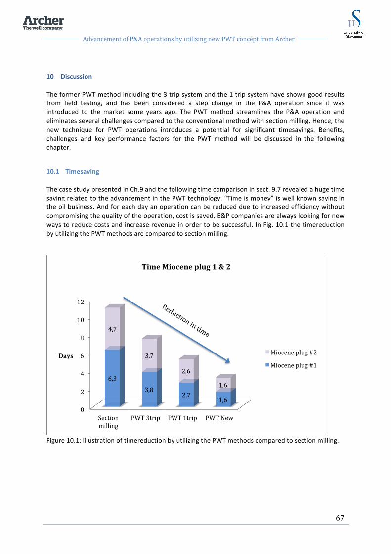
Advancement of P&A operations by utilizing new PWT concept from Archer
67
10 Discussion The former PWT method including the 3 trip system and the 1 trip system have shown good results from field testing, and has been considered a step change in the P&A operation since it was introduced to the market some years ago. The PWT method streamlines the P&A operation and eliminates several challenges compared to the conventional method with section milling. Hence, the new technique for PWT operations introduces a potential for significant timesavings. Benefits, challenges and key performance factors for the PWT method will be discussed in the following chapter.
10.1 Timesaving The case study presented in Ch.9 and the following time comparison in sect. 9.7 revealed a huge time saving related to the advancement in the PWT technology. “Time is money” is well known saying in the oil business. And for each day an operation can be reduced due to increased efficiency without compromising the quality of the operation, cost is saved. E&P companies are always looking for new ways to reduce costs and increase revenue in order to be successful. In Fig. 10.1 the timereduction by utilizing the PWT methods are compared to section milling.
Figure 10.1: Illustration of timereduction by utilizing the PWT methods compared to section milling.
0
2
4
6
8
10
12
Section milling
PWT 3trip PWT 1trip PWT New
6,3
3,8 2,7
1,6
4,7
3,7
2,6
1,6
Days
Time Miocene plug 1 & 2
Miocene plug #2
Miocene plug #1
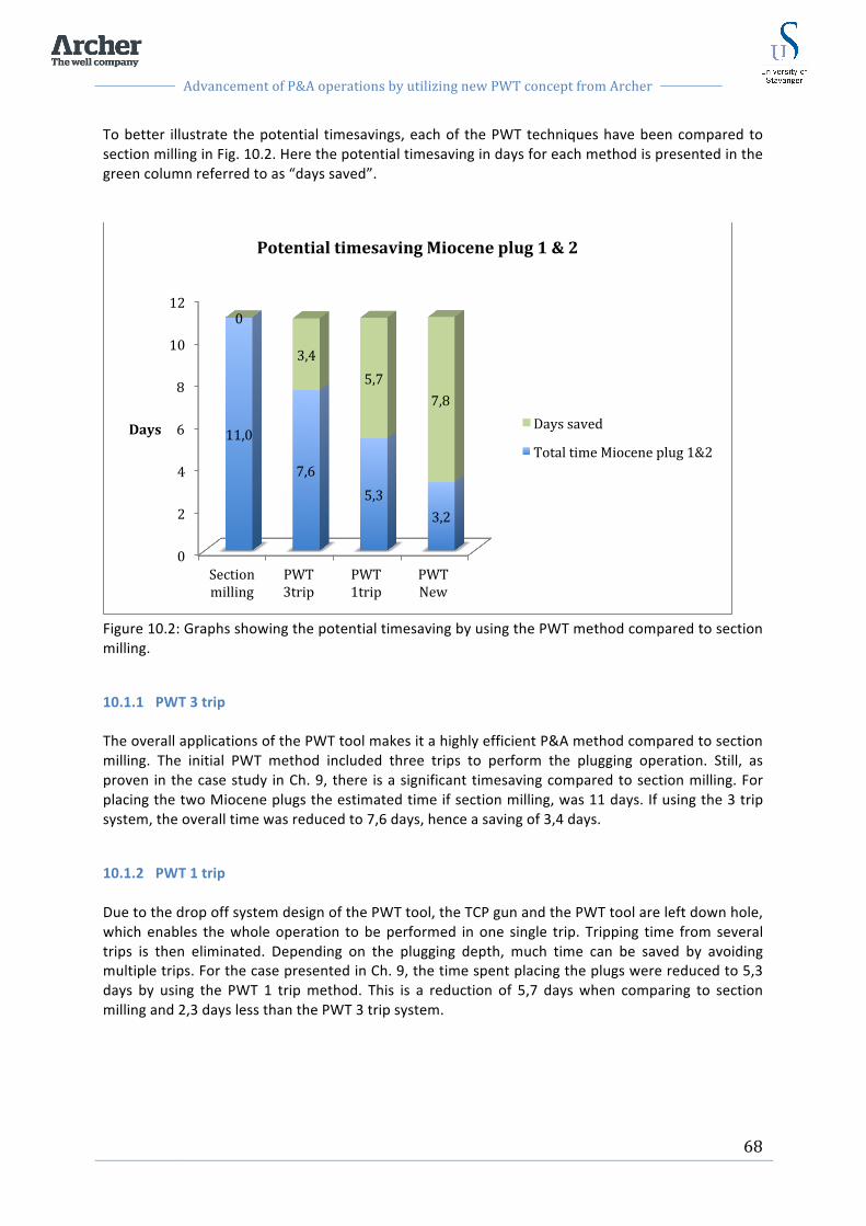
Advancement of P&A operations by utilizing new PWT concept from Archer
68
To better illustrate the potential timesavings, each of the PWT techniques have been compared to section milling in Fig. 10.2. Here the potential timesaving in days for each method is presented in the green column referred to as “days saved”.
Figure 10.2: Graphs showing the potential timesaving by using the PWT method compared to section milling.
10.1.1 PWT 3 trip The overall applications of the PWT tool makes it a highly efficient P&A method compared to section milling. The initial PWT method included three trips to perform the plugging operation. Still, as proven in the case study in Ch. 9, there is a significant timesaving compared to section milling. For placing the two Miocene plugs the estimated time if section milling, was 11 days. If using the 3 trip system, the overall time was reduced to 7,6 days, hence a saving of 3,4 days.
10.1.2 PWT 1 trip Due to the drop off system design of the PWT tool, the TCP gun and the PWT tool are left down hole, which enables the whole operation to be performed in one single trip. Tripping time from several trips is then eliminated. Depending on the plugging depth, much time can be saved by avoiding multiple trips. For the case presented in Ch. 9, the time spent placing the plugs were reduced to 5,3 days by using the PWT 1 trip method. This is a reduction of 5,7 days when comparing to section milling and 2,3 days less than the PWT 3 trip system.
0
2
4
6
8
10
12
Section milling
PWT 3trip
PWT 1trip
PWT New
11,0
7,6 5,3
3,2
0
3,4 5,7
7,8
Days
Potential timesaving Miocene plug 1 & 2
Days saved
Total time Miocene plug 1&2

Advancement of P&A operations by utilizing new PWT concept from Archer
69
10.1.3 New PWT technique The new PWT technique with pumping cement through the outlet ports of the high pressure washer introduces a more efficient method to perform the PWT operation. Considerable timesavings are achieved due to improved cement placement design and elimination of traditional cement squeezing and WOC. When comparing to section milling as presented in graph 10.2 one can save 7,8 days when utilizing the new PWT technique for setting two cement barriers as described in the case study in Ch.9. When considering the advancement in PWT technology the case reveals that the new PWT technique saves 4,4 days compared to the 3 trip system and 2,1 days compared to the 1 trip system. The potential saving of 7,8 days might not seem very much, but considering todays rig rates, ranging from around 300.000$-‐ 600.000$ per day, 7,8 days represents a significant cost. However, by utilizing the new PWT technique an extra trip is required with wireline in order to perforate the plugging section. This wireline trip requires some additional time in rig up and tripping. Still, it is considerably faster to perform tripping with wireline compared to drill pipe, where connections must be made up between pipes.
10.1.4 P&A Campaigns To better illustrate the potential savings utilizing the PWT tool, a so-‐called “P&A campaign” with plugging a whole field of 36 wells is presented in Fig. 10.3. P&A campaigns are continuously performed as whole fields or platforms are shut down at the end of their lifecycle. In the years to come, the number of such campaigns will increase due to the many “old” fields that are no longer profitable. The graph in Fig. 10.3 is based on the exact same data as for the case study. However, for this graph the time for placing Miocene plug 1 and 2 is multiplied by 36 due to the 36 wells in the P&A campaign. The time presented in the graph only represents placing the two Miocene plugs, not time spent on the remaining plugging of the wells.

Advancement of P&A operations by utilizing new PWT concept from Archer
70
Figure 10.3: Graphs showing the total time to place 36 plugs during a P&A campaign. Fig. 10.3 shows a significant difference in time used for section milling compared to the PWT method for placement of Miocene plug 1 and 2 in 36 wells. By looking at the bigger picture, the overall timesaving can more easily be displayed. Fig. 10.3 shows that 396 days were estimated for placing the plugs by section milling operation. For the 3 trip PWT method, 272 days were estimated to place the two plugs. By applying the 1 trip PWT method, 190 days were estimated. And finally 116 days were estimated by utilizing the new PWT technique. In Fig. 10.4 the three PWT methods have been compared to section milling for the 36 wells. As we can see from the graph an estimated 124 days can be saved by applying the 3 trip PWT method, 206 days by the 1 trip PWT method and 280 days by the new PWT technique. Again, the potential saving of 280 days by utilizing the new PWT method for placing the two Miocene plugs in 36 wells is significant.
0
50
100
150
200
250
300
350
400
Section milling
PWT 3trip
PWT 1trip
PWT New
396
272 190
116
Days
Total time to plug 36 wells
Total time to plug 36 wells
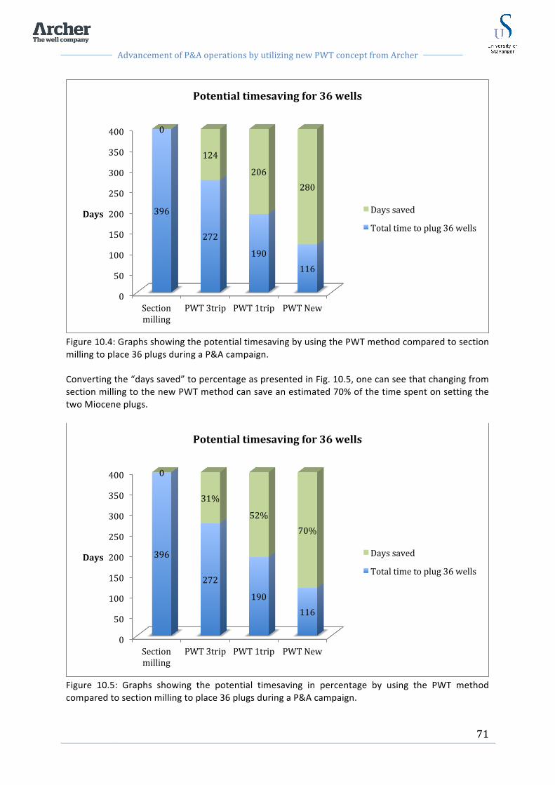
Advancement of P&A operations by utilizing new PWT concept from Archer
71
Figure 10.4: Graphs showing the potential timesaving by using the PWT method compared to section milling to place 36 plugs during a P&A campaign. Converting the “days saved” to percentage as presented in Fig. 10.5, one can see that changing from section milling to the new PWT method can save an estimated 70% of the time spent on setting the two Miocene plugs.
Figure 10.5: Graphs showing the potential timesaving in percentage by using the PWT method compared to section milling to place 36 plugs during a P&A campaign.
0
50
100
150
200
250
300
350
400
Section milling
PWT 3trip PWT 1trip PWT New
396
272
190 116
0
124
206 280
Days
Potential timesaving for 36 wells
Days saved
Total time to plug 36 wells
0
50
100
150
200
250
300
350
400
Section milling
PWT 3trip PWT 1trip PWT New
396
272
190 116
0
31%
52% 70%
Days
Potential timesaving for 36 wells
Days saved
Total time to plug 36 wells

Advancement of P&A operations by utilizing new PWT concept from Archer
72
A time reduction of 70% by utilizing the new PWT technique compared to section milling is again significant. Reducing the operational time for setting the two Miocene plugs by 70% implies a significant cost reduction. The numbers presented in the graphs above represents a considerable increase in efficiency by utilizing the PWT technique compared to section milling. However, the new PWT technique is yet to be field proven. This technique will need to be approved in the field and verified by drilling out the cement plug and log the annulus before a conclusion of the method can be established. However, Archer has confidence in the concept based on estimates, calculations, and previous experience within PWT operations. The new technique for the PWT tool has generated great interests from potential clients and will soon be applied as a worlds first. Within the end of 2013, the tool is scheduled for its first job in the North Sea [32].
10.2 Benefits with PWT 1 trip and 3 trip The PWT tool introduces several benefits compared to conventional P&A operations. Some of these benefits are presented below. Many of these benefits contribute to a more efficient P&A operation and thereby considerable timesavings.
10.2.1 Effective rock-‐to-‐rock cement barrier By perforating the casing and washing out the annular content, direct contact between the cement and the formation is achieved. Cement is pumped to completely fill the annular space and the wellbore and establish full cross sectional sealing of the well. Hence, the PWT method is an efficient way to place a rock-‐to-‐rock cement barrier in a well.
10.2.2 Avoid removing casing The PWT operation is designed to access the formation through perforation holes in order to place a rock-‐to-‐rock cement barrier without removing the casing. Casing removal can be difficult if the casing is stuck and several cut and pull operations might be necessary. This operation might be time consuming and challenging. Since the PWT method eliminates the need for pulling the casing, valuable rig time is saved.
10.2.3 Eliminates need for section milling The PWT concept was developed to improve efficiency of the P&A operation and avoid the challenges of section milling operations. As described in sect. 7.2.1, section milling operations are time consuming and pose several operational challenges. Open hole exposure can be challenging, especially if the fracture pressure is close to the pore pressure. In addition there are considerable challenges related to the generated swarf and handling of the swarf not to damage equipment nor to be a HSE issue. Compared to section milling the PWT method is less time consuming, not dependent on a large pressure window to be successful and eliminates the challenges of swarf handling. On the other hand the PWT method is highly dependent on sufficient washing of the annular space and displacement of the previous fluids to complete a successful plugging operation.

Advancement of P&A operations by utilizing new PWT concept from Archer
73
As the cement plug is in place it should be properly verified. For cement plugs set after section milling it is not possible to perform the same comprehensive verification as for the PWT method. When section milling is performed prior to plug setting, the top of the plug could end up below the casing in the open hole or inside the cased hole. If the top of cement ends up inside the casing, a pressure test would only test the cement inside the casing and the casing, not the annular cement. Hence the cement integrity of the cross sectional barrier can not be fully verified. For PWT operations the cement plug inside the casing can be drilled out and the perforated interval can be logged with CBL and USIT logs as described in sect. 6.5, to verify cement integrity. Then the plug is re-‐cemented to complete the cross sectional barrier. This method of drilling out the cement plug to run logs is not applicable for section milling set plugs. The cement used for plugging is often harder than the formation, and hence the drilling bit would most likely slide off the cement plug and kick off into the formation. However, as the PWT method gets further approved through field testing and verification of successful plugs in place, drilling and logging to verify cement integrity will not be necessary. The method will then be accepted as a standard method, satisfying the P&A plugging requirements.
10.2.3.1 Eliminates the challenges of swarf handling By eliminating section milling the challenges regarding swarf handling will also be eliminated. Swarf handling introduces several challenges and is highly undesirable on any rig. By eliminating swarf the rig is kept clean and neither personnel nor equipment gets exposed to swarf.
10.2.4 High circulation rates The PWT tool is designed to handle high circulation rates through multiple flow paths within the tool. High circulation rates are necessary to achieve efficient washing of the annular, and to lift debris from the washing job up to surface. It is very unlikely to take a kick during the PWT operation. However, it is possible that gas can be trapped behind the casing. As the casing is perforated this gas can enter the wellbore and rise to the surface. With the PWT tool you have the opportunity to achieve high circulate rate through the bypass system, which can be applied to circulate out such potential gas.
10.2.5 Adjustable distance between swab cups To optimize the washing and determine the intensity and the amount of wash fluid to flush the annular, the distance between upper and lower swab cups can be adjusted. If the distance between swab cups is small, the isolated area between the swab cups will be small hence washing will be more intense. If the distance between the cups is extended a bigger volume of wash fluid will flush the isolated area but with a lower intensity. Swab cup distance should be adjusted to optimize washing in the well where it is applied.
10.2.6 Reliable tool due to dual swab cup design The dual swab cup design is developed to benefit the reliability of the PWT tool. The secondary swab cups are installed as backup to the primary swab cups. The secondary swab cups also improve the sealing capacity between the cups.

Advancement of P&A operations by utilizing new PWT concept from Archer
74
10.2.7 Flow by-‐pass system The flow by-‐pass system is designed to be able to determine the flow path for the different applications of the PWT operation. While tripping in the well it is desirable to circulate through the by pass system in the tool to avoid surge and swab effects due to the swab cups. The by-‐pass system allows for higher tripping speed and contributes to higher circulation rates to lift debris if it starts to pack off in the well above the PWT tool during washing.
10.3 Benefits with the new PWT technique In addition to the benefits described above, the new PWT technique introduces two unique benefits that separate this technique from the previous PWT method.
10.3.1 Traditional squeeze avoided As described in Ch.8 the 1 trip and 3 trip PWT methods are dependent on the cement squeeze method to set the plug. This implies that after the plug is in place, the open-‐ended work string, or cement stinger, must be kept in the hole to maintain the pressure until the cement is sufficiently set. Based on history from past cement jobs it can be assumed that the squeeze pressure must be held for an average of 16-‐24 hours depending on the cement design [32]. By applying the new PWT technique, cement is forced into the annular space through the sealed area between the swab cups. Cement is placed from bottom and up to completely fill up the annulus and the well. Excess cement is then placed in the well to about 165 ft. above the upper perforations to ensure sufficient sealing properties of the cement plug. When this operation is done and cement is in place, the PWT tool can immediately be pulled out of the hole allowing the rig to be ready for next operation. This implies that the need for squeeze cementing is eliminated for the new PWT technique. By eliminating squeeze cementing, the time spent down hole to hold the squeeze is also eliminated. This implies a potential timesaving of 16-‐24 hours by applying the new PWT technique.
10.3.2 Ensure cement throughout the annular Another benefit of the new PWT technique is the cement placement design. Since cement is placed through the isolated area between the swab cups, cement is forced through every single perforation hole and into the annular space. By doing this cement is ensured behind every single perforation and thereby the annulus is more efficiently filled up from bottom and up. This technique reduces the possibility of channeling and spots of fluid embedded in the cemented interval.

Advancement of P&A operations by utilizing new PWT concept from Archer
75
10.4 Challenges and key performance factors with PWT operations
10.4.1 Downhole conditions and annular content In the P&A planning and execution phase it is important with extensive understanding of the downhole conditions. The downhole conditions are evaluated through logging operations as described in sect. 6.5. For P&A operations the well should be re-‐logged prior to the operation rather than looking at old logs due to the potential of changes in the wellbore over time. The evaluation of the logs will determine what P&A method that will be the best for the respective well. An essential factor to determine the applicable P&A method is the annular sealing in the plugging area. If the annular sealing is verified and accepted as a competent barrier, a balanced plug can be set inside the cased hole. If the annular sealing is insufficient the options are section milling or the PWT method. If significant amounts of cement are present in the annulus, efficient PWT washing can be challenging, and section milling might be the best option. On the other hand, if the annulus contains old fractured cement and fluid, the PWT method applies. For the PWT method, the annular content must be known and evaluated to ensure the content allows efficient washing and to design a wash fluid with correct properties.
10.4.2 Washing and displacement For a successful PWT operation it is essential with a completely clean annulus as a result of a good washing and hole-‐cleaning job. A proper washing job will depend on good interpretation of the annular content from the logs, proper washing fluid properties and good monitoring of pressure decrease. However, there are uncertainties related to the washing and one cannot be completely sure of a clean annulus. A successful washing job is based on the assumption that pressure reduction from the flow trough the annulus and clean returns indicate a clean annulus. The PWT operation is also dependent on the displacement of washfluid by spacer fluid as well as displacement of the spacer fluid by cement slurry. To avoid contamination of the cement all void spaces in the annulus and in the well must be completely displaced. If the displacement is insufficient, fluids can create void spaces and channels in the cement leading to potential leakages.
10.4.3 Contamination of cement As the cement is pumped to displace the spacer it is expected a certain amount of mixing in the interface. As cement is mixed with spacer fluid the isolation properties of the cement is affected. The cement should therefore be designed with optimal additives to maintain long-‐term isolation. Amongst the additives there should be expanding agents to avoid bulk shrinkage and fibers to increase the tensile strength of the cement.
10.4.4 Possibly spots of fluid embedded in the cement interval Spots of fluid embedded in the cement are a general challenge when performing cement jobs. Cement must therefore be designed with optimal rheology to completely displace the spacer fluid and ensure minimum mixing of the wellfluids. Also it is essential for a good cement job to pump the
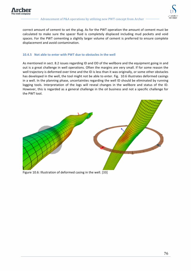
Advancement of P&A operations by utilizing new PWT concept from Archer
76
correct amount of cement to set the plug. As for the PWT operation the amount of cement must be calculated to make sure the spacer fluid is completely displaced including mud pockets and void spaces. For the PWT cementing a slightly larger volume of cement is preferred to ensure complete displacement and avoid contamination.
10.4.5 Not able to enter with PWT due to obstacles in the well As mentioned in sect. 8.2 issues regarding ID and OD of the wellbore and the equipment going in and out is a great challenge in well operations. Often the margins are very small. If for some reason the well trajectory is deformed over time and the ID is less than it was originally, or some other obstacles has developed in the well, the tool might not be able to enter. Fig. 10.6 illustrates deformed casings in a well. In the planning phase, uncertainties regarding the well ID should be eliminated by running logging tools. Interpretation of the logs will reveal changes in the wellbore and status of the ID. However, this is regarded as a general challenge in the oil business and not a specific challenge for the PWT tool.
Figure 10.6: Illustration of deformed casing in the well. [33]

Advancement of P&A operations by utilizing new PWT concept from Archer
77
10.4.6 Possibly poorly or non-‐ centralized casing A non-‐centralized casing is illustrated in Fig. 10.7. Non-‐centralized casings could bring trouble to performing the PWT operation. Washing as well as placement of cement would be difficult if the casing is leaning towards the formation on the low side. The annular space would then be larger on the outer side, and narrow on the low side. The annulus might not allow sufficient washing and could cause trouble for cement placement. Depending on the formation type it could result in an insufficient barrier in the wellbore. Section milling would probably be a better alternative in a well with non-‐centralized casing, to make sure the casing and cement is removed in order for the cement plug to cover the wellbore completely as a rock-‐to-‐rock barrier.
Figure 10.7: Illustration of a non-‐centralized casing seen from above.
10.4.7 Deviated wells PWT operations in highly deviated wells may introduce some challenges compared to straight vertical wells. In a deviated wellbore the tool will rest on its lower side towards the lower casing wall. The distance from the TCP gun and PWT tool will therefore be less on the low side than on the high side. This distance will affect the perforations and also the washing of the annular space. Since the perforation gun distance to the inner casing wall is small on the lower side, these perforations will generate larger holes than on the upper side. However, that is not a disadvantage in this case. Over time the solid particles and barite in the annulus will settle. These particles will then settle on the lower side due to gravity. It is therefore a benefit for efficient washing and annular cleaning that the perforation holes are larger on the lower side and will contribute to easier passage of solid particles. On the upper side there will not be as much settled particles and therefore the slightly smaller holes would be sufficient to circulate out the dirt.
10.4.8 Perforated pipe is weakened As mentioned in sect. 8.2.1.1, the casing strength will be reduced when perforated. In the PWT operation the diagonal path of the perforations will make the reduction small, and it its not considered a big problem. The cement placed in the well and annulus will support the casing and protect it against corrosion and stresses from the formation. However, the perforated casing may posses another threat. The perforation holes create flow paths from the reservoir and into the
Cement Well
Annular cement Formation
Non-‐ centralized casing
Advancement of P&A operations by utilizing new PWT concept from Archer
78
wellbore if they are not completely sealed off by cement. It is therefore very important that the cement job is good and that the cement do not get channels nor void spaces that can lead reservoir fluids through the perforated holes and into the wellbore. In addition there will be placed some 100 ft. (ca. 30,5m) of excess cement above the perforations inside the casing that will further prevent leakages into the wellbore.
10.4.9 Multiple casing strings To perform PWT operations in wellsections with multiple casing strings is a debated topic associated with several uncertainties. First this well section must be logged to evaluate the multiple annulars and determine the annular content. Technology currently in use only allows for cement logging behind one single tubular. The next challenge would be the perforations. The perforation charges could most likely be adjusted to perforate through multiple casings. However, it would still be uncertainties related to the annular content that would affect the perforations. If solid cement is present in the annulus the perforations might not get through to penetrate the outer casing. Also for the washing sequence there are uncertainties regarding where exactly the washing will take place. Depending on the perforations, and the annular content, the washing might happen behind the first casing wall, behind the second wall or both. Ideally, efficient washing must be performed in all annulars to be able to place a good cement plug after washing. Also the cement part of the operation would be depending on a clean annulus completely displaced by spacer fluid. With that being said, technology is continuously moving forward and multiple casing strings might be an application for the PWT tool in the near future.
10.5 New applications for PWT operations To maintain well integrity and continue production or development of an old well, the annular cement must be verified and approved as described in sect. 6.5. Not only prior to P&A operations, but simply to verify the integrity of the well. In some cases the annular cement is bad conditioned and interpretation of the logs may detect sections with cracks and fractured cement. This is a severe problem that needs to be fixed to maintain the well operation. Recently it was suggested that the PWT method could be used for this purpose. The idea was to perforate the casing in the well section with bad annular cement. Then place the swab cups over the perforations and squeeze cement into this area. The cement would then be circulated through the perforations and fill in the void spaces and cracks of the cement to complete a good annular sealing. However, this application needs comprehensive research and testing before it can be applied. Another potential application area for the PWT tool is running the PWT tool on coil tubing. If this is enabled it would be a big step in the direction of rigless P&A. Rigless P&A will contribute to less rig shortage and a considerable decreased scope and cost of todays P&A operations. However, there are several challenges that need to be sorted out in order to make this possible. The PWT concept has advanced significantly with the introduction of the new PWT technique compared to the initial PWT 3 trip method. Further work on the PWT concept might open for further development of the PWT concept and expand the PWT applications in the future.
Advancement of P&A operations by utilizing new PWT concept from Archer
79
11 Conclusion P&A operations are time consuming and costly for the E&P companies. However, permanent P&A must be performed on every drilled well all over the world. On the NCS several fields are approaching the end of production and several thousand wells will be permanently plugged within the next 5-‐25 years [34]. To save valuable rig time and reduce the cost of P&A operations, new methods and technologies have been developed, one of them being the PWT tool. The PWT tool has a potential in providing more efficient P&A operations and might be a solution for the upcoming wave of P&A work. The main conclusions from this work can be summarized as follows:
-‐ The main overall challenge regarding P&A is to reduce cost by doing P&A more efficiently with a minimum amount of rig time, without compromising the quality. The P&A operation must be performed right the first time to avoid remedial costs from well re entry due to failed barriers.
-‐ The conventional methods of P&A includes section milling which is time consuming and
possess several challenges and uncertainties. Section milling is regarded as an undesirable operation for the E&P companies.
-‐ PWT method is applicable if free pipe is available at an acceptable plugging depth. If free
pipe is not available and annular sealing is insufficient, section milling must be performed to establish a permanent barrier.
-‐ PWT set plugs can be properly verified and tested by drilling through the plug and log the
annular cement in the plugged interval. As the plug is re-‐cemented the plug integrity can be pressure tested, load tested and tagged. Section milling deployed plugs cannot be tested and verified the same way.
-‐ The PWT methods introduce an efficient solution to place a rock-‐to-‐rock cross sectional
cement barrier without removing the casing. The PWT method eliminates section milling and the challenges and uncertenties related to section milling operations. Compared to section milling, considerable timesavings are also achieved especially by the 1 trip PWT method and the new PWT technique. With the amount of wells that are to be plugged the coming years, and the limited availability of rigs, saving time on P&A operations are crucial for the E&P companies.
-‐ The new technique for PWT operations is yet to be field proven. As this technique is field
proven, given that good results are obtained and verification of the plugging operations are achieved, the new PWT technique has great potential. According to the case study in Ch.9, the estimated operational time to place two Miocene plugs in an Ekofisk well can be reduced by 70% by applying the new PWT technique.
-‐ The new PWT technique introduces an efficient cement placement design through outlet
ports of the high pressure washer, between the swab cups. The swab cups can handle pressures up to 5000 psi (345 bar) which will provide a squeeze pressure to sufficiently force cement into the annular space and fill it completely. This cement placement design

Advancement of P&A operations by utilizing new PWT concept from Archer
80
eliminates the time spent on traditional squeezing. Hence, significantly shorter time is spent on the plugging operation.
-‐ As it gets field proven, the new PWT technique is recommended due to the efficiency, plug
quality and timesavings provided by this method.
-‐ Multiple casing strings might be applicable for the PWT method in the future if technology moves on and logging through multiple casings is made possible.
-‐ For further development, the PWT method should be adapted for deployment on coil tubing
as this could open for rigless P&A and even wider industry appreciation.
-‐ Future field experience and approval of the PWT method will potentially open for further development of the equipment and the method and expand the PWT applications.

Advancement of P&A operations by utilizing new PWT concept from Archer
81
12 References [1] Abshire, l.W., Desai, P., Mueller, D., Paulsen, W. B., Robertson, R.D.B, Solheim, T.: Offshore Permanent Well Abandonment, Oilfield Review Spring 2012:24, no1. [2] D. Liversidge and S. Taoutaou and S.Agarwal, Permanent Plug and Abandonment Solution for the North Sea. SPE 100771, 2006. [3] NORSOK Standard D-‐010 Rev, 3, August 2004. Removing equipment above seabed p.67 [4] NORSOK Standard D-‐010 Rev, 3, August 2004. Permanent abandonment, p.63-‐64. [5] Abshire, l.W., Desai, P., Mueller, D., Paulsen, W. B., Robertson, R.D.B, Solheim, T.: Offshore Permanent Well Abandonment, Oilfield Review Spring 2012:24, no1. [6] Petroleum Safety Authority Norway, THE ACTIVITIES REGULATIONS, Petroleum Safety Authority Norway, Editor. [7] NORSOK Standard D-‐010 Rev, 3, August 2004. Well integrity definition p.12 [8] B. Vignes, Contribution to Well Integrity and Increased Focus on Well Barriers from a Life Cycle Aspect, Stavanger: University of Stavanger, 2011. [9] Petroleum Safety Authority Norway, The facilities regulation, Petroleum Safety Authority Norway, Editor. Section 48, Well Barriers. [10] Petroleum Safety Authority Norway, The activities regulations, Petroleum Safety Authority Norway, Editor. Section 88, Securing wells. [11] www.ptil.no, PSA Well Integrity Survey, Phase 1 summary report [12] B. Vignes, Contribution to Well Integrity and Increased Focus on Well Barriers from a Life Cycle Aspect, Stavanger: University of Stavanger, 2011. [13] Celia, M.A., Bachu, S., Nordbotten, J.M., Kavetski, D., Gasda, S.E.: Modeling Critical Leakage Pathways in a Risk Assessment Framework: Representation of Abandoned Wells, 2005. [14] NORSOK Standard D-‐010 Rev, 3, August 2004. Well barriers, General p.13 [15] B. Vignes, Contribution to Well Integrity and Increased Focus on Well Barriers from a Life Cycle Aspect, Stavanger: University of Stavanger, 2011. [16] NORSOK Standard D-‐010 Rev, 3, August 2004. Cement plug, Acceptance criteria p.132 [17] Abshire, l.W., Desai, P., Mueller, D., Paulsen, W. B., Robertson, R.D.B, Solheim, T.: Offshore Permanent Well Abandonment, Oilfield Review Spring 2012:24, no1. [18] Saasen, A., Wold, S., Ribesen, B.T., Tran, T.N,. et al.: Permanent Abandonment of a North Sea Well Using Unconsolidated Well-‐ Plugging Material, SPE 133446-‐PA, 2011.
Advancement of P&A operations by utilizing new PWT concept from Archer
82
[19] Wellcem AS. ThermaSet, Homepage 2013. http://www.wellcem.no/thermaset-‐reg.html [20] Williams, S., Carlsen, T., Constable, K., Guldahl, A.: Identification and Qualification of Shale Annular Barriers Using Wireline Logs During Plug and Abandonment Operations, SPE 119321-‐MS, 2009. [21] Calvert D.G., Smith D.K.: API Oilwell Cementing Practices, 1990. [22] Halliburton home page, Squeeze cementing. [23] Heart energy E&P webpage, Effective cement plugs, November 2003. http://www.epmag.com/EP-‐Magazine/archive/Effective-‐cement-‐plugs_2694 [24] CSI Technologies.: Cement Plug Testing: Weight vs. Pressure Testing to Assess Viability of a wellbore Seal Between Zones, 2011. [25] P. Pilkington, "SPE 20314 Cement Evaluation -‐ Past, Present, and Future," JPT February 1992, 1992. [26] Shook, E.H., Frisch, G.J., Lewis, T.: Cement Bond Evaluation, SPE 108415, 2008. [27] Illustrations of CBL and UST logging: http://www.bridge7.com/grand/log/gen/casedhole/cbl.htm [28] Boyd, D., Al-‐ Kubti, S., et al.:Reliability of Cement Bond Log Interpretatons Compared to Physical Communication Tests between Formations, SPE 101420, 2006. [29] P&A forum, challenges with P&A, Stavanger 2012. [30] Challenges with milling operations, presentation by Siddhartha Lunkad (Statoil) at UIS, November 2012. [31] P&A forum, Downhole swarf Deposition, Swarfpack presentation, Stavanger 2012. [32] Personal conversation with Sverre Bakken, Archer. [33] http://www.noetic.ca/well-‐integrity-‐management/ [34] Statoil innovative, P&A challenge: http://innovate.statoil.com/challenges/Pages/PlugAndAbandonment.aspx

Advancement of P&A operations by utilizing new PWT concept from Archer
83
13 Appendix A

Advancement of P&A operations by utilizing new PWT concept from Archer
84

Advancement of P&A operations by utilizing new PWT concept from Archer
85
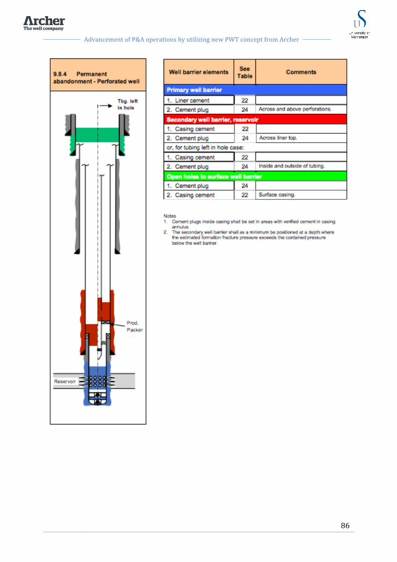
Advancement of P&A operations by utilizing new PWT concept from Archer
86

Advancement of P&A operations by utilizing new PWT concept from Archer
87
14 Appendix B