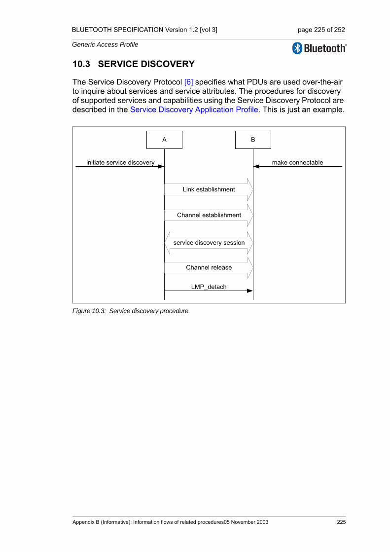
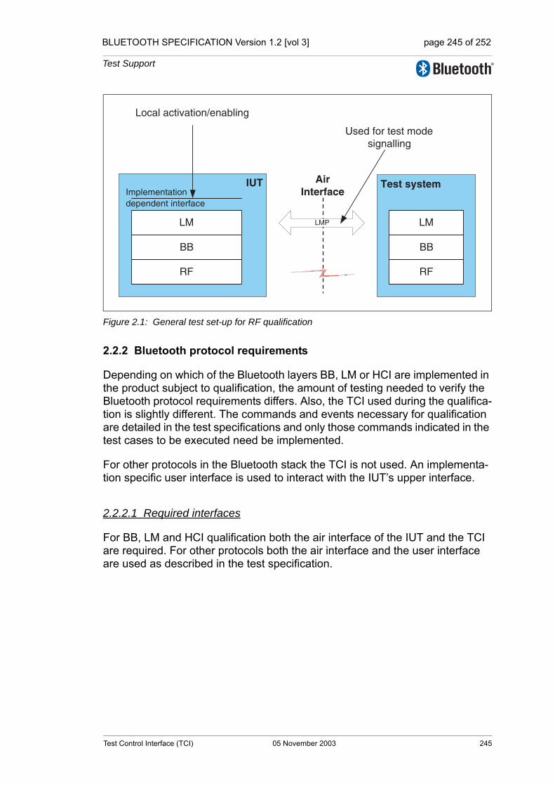
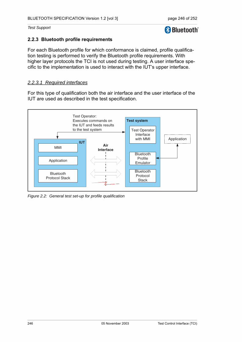
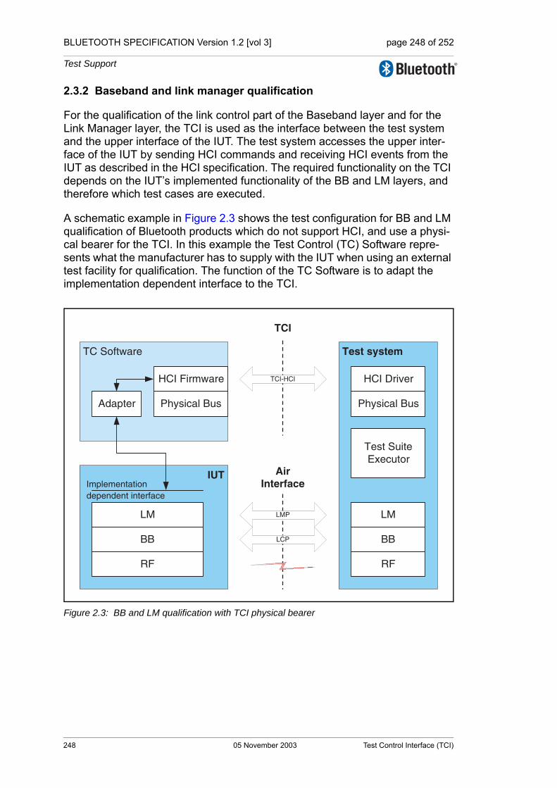
Embed Size (px)
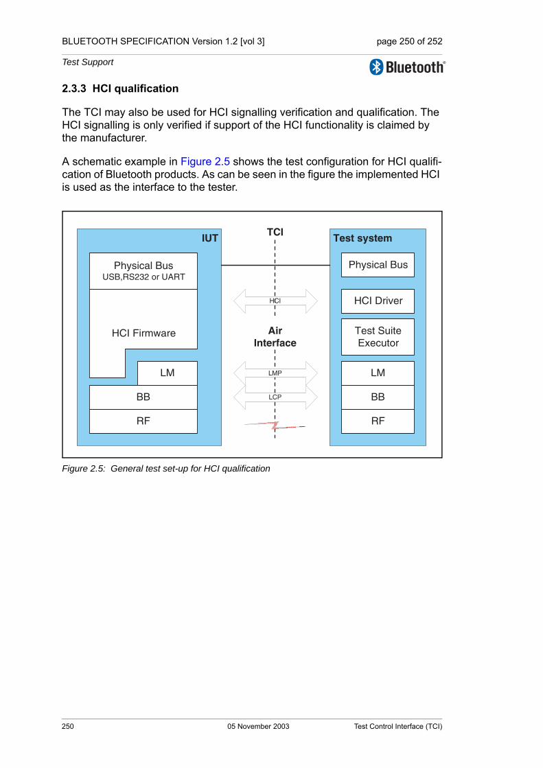
Citation preview

Specificationof the Bluetooth System
Wireless connections made easy
Master Table of Contents &ComplianceRequirementsCovered Core Package version: 1.2Current Master TOC issued: 05 November 2003
Specification Volume 0
BLUETOOTH SPECIFICATION [vol 0] page 2 of 76
Revision History
The Revision History is shown in the “Appendix” on page 53[vol. 0].
Contributors
The persons who contributed to this specification are listed in “Appendix” on page 53[vol. 0].
Web Site
This specification can also be found on the Bluetooth website: http://www.bluetooth.com
Disclaimer and Copyright Notice
The copyright in these specifications is owned by the Promoter Members of Bluetooth SIG, Inc. (“Bluetooth SIG”). Use of these specifications and any related intellectual property (collectively, the “Specification”), is governed by the Promoters Membership Agreement among the Promoter Members and Blue-tooth SIG (the “Promoters Agreement”), certain membership agreements between Bluetooth SIG and its Adopter and Associate Members (the “Member-ship Agreements”) and the Bluetooth Specification Early Adopters Agreements (“1.2 Early Adopters Agreements”) among Early Adopter members of the unin-corporated Bluetooth special interest group and the Promoter Members (the “Early Adopters Agreement”). Certain rights and obligations of the Promoter Members under the Early Adopters Agreements have been assigned to Blue-tooth SIG by the Promoter Members.
Use of the Specification by anyone who is not a member of Bluetooth SIG or a party to an Early Adopters Agreement (each such person or party, a “Mem-ber”), is prohibited. The legal rights and obligations of each Member are gov-erned by their applicable Membership Agreement, Early Adopters Agreement or Promoters Agreement. No license, express or implied, by estoppel or other-wise, to any intellectual property rights are granted herein.
Any use of the Specification not in compliance with the terms of the applicable Membership Agreement, Early Adopters Agreement or Promoters Agreement is prohibited and any such prohibited use may result in termination of the appli-cable Membership Agreement or Early Adopters Agreement and other liability permitted by the applicable agreement or by applicable law to Bluetooth SIG or any of its members for patent, copyright and/or trademark infringement.
2 05 November 2003

BLUETOOTH SPECIFICATION [vol 0] page 3 of 76
THE SPECIFICATION IS PROVIDED “AS IS” WITH NO WARRANTIES WHATSOEVER, INCLUDING ANY WARRANTY OF MERCHANTABILITY, NONINFRINGEMENT, FITNESS FOR ANY PARTICULAR PURPOSE, SATIS-FACTORY QUALITY, OR REASONABLE SKILL OR CARE, OR ANY WAR-RANTY ARISING OUT OF ANY COURSE OF DEALING, USAGE, TRADE PRACTICE, PROPOSAL, SPECIFICATION OR SAMPLE.
Each Member hereby acknowledges that products equipped with the Blue-tooth® technology (“Bluetooth® Products”) may be subject to various regula-tory controls under the laws and regulations of various governments worldwide. Such laws and regulatory controls may govern, among other things, the combi-nation, operation, use, implementation and distribution of Bluetooth® Prod-ucts. Examples of such laws and regulatory controls include, but are not limited to, airline regulatory controls, telecommunications regulations, technology transfer controls and health and safety regulations. Each Member is solely responsible for the compliance by their Bluetooth® Products with any such laws and regulations and for obtaining any and all required authorizations, per-mits, or licenses for their Bluetooth® Products related to such regulations within the applicable jurisdictions. Each Member acknowledges that nothing in the Specification provides any information or assistance in connection with securing such compliance, authorizations or licenses. NOTHING IN THE SPECIFICATION CREATES ANY WARRANTIES, EITHER EXPRESS OR IMPLIED, REGARDING SUCH LAWS OR REGULATIONS.
ALL LIABILITY, INCLUDING LIABILITY FOR INFRINGEMENT OF ANY INTELLECTUAL PROPERTY RIGHTS OR FOR NONCOMPLIANCE WITH LAWS, RELATING TO USE OF THE SPECIFICATION IS EXPRESSLY DIS-CLAIMED. BY USE OF THE SPECIFICATION, EACH MEMBER EXPRESSLY WAIVES ANY CLAIM AGAINST BLUETOOTH SIG AND ITS PROMOTER MEMBERS RELATED TO USE OF THE SPECIFICATION.
Bluetooth SIG reserves the right to adopt any changes or alterations to the Specification as it deems necessary or appropriate and to adopt a process for adding new Bluetooth® profiles after the release of the Specification.
Copyright © 1999, 2000, 2001, 2002, 2003
Agere Systems, Inc.,Ericsson Technology Licensing, AB,IBM Corporation,Intel Corporation,Microsoft Corporation,Motorola, Inc.,Nokia Corporation,Toshiba Corporation
*Third-party brands and names are the property of their respective owners.
05 November 2003 3

BLUETOOTH SPECIFICATION [vol 0] page 4 of 76
4 05 November 2003
Master Table of Contents & Compliance Requirements
Part AMASTER TABLE OF CONTENTSBluetooth Specification
Including Core v1.2
This table of contents (TOC) covers the entire Bluetooth Specification. In addition, each volume has a TOC and each part of a volume is preceded by a detailed TOC.

BLUETOOTH SPECIFICATION [vol 0] page 6 of 76
Master Table of Contents
6 05 November 2003

BLUETOOTH SPECIFICATION [vol 0] page 7 of 76
MASTER TOC FOR THE BLUETOOTH SPECIFICATION
In the following table:
• The TOC for each Volume starts at the top of a page.
• The Volume No. is written in red and followed by the name of the Volume.
Note: Each Volume is a self contained book which is published and updated separately and is equipped with a TOC of its own. However, this Master TOC is also revised as soon as any of the other Volumes are updated.
• A Volume cover one or more Parts (A, B, etc.), each Part can be viewed independently and has its own TOC.
Red or blue text on the following pages indicates hypertext links that will take you directly to the indicated section, on condition that you have access to a complete specification.
05 November 2003 7

BLUETOOTH SPECIFICATION [vol 0] page 8 of 76
8 05 November 2003

BLUETOOTH SPECIFICATION [vol 0] page 9 of 76
Specification Volume 0Master Table of Contents & Compliance Requirements
Part AMASTER TABLE OF CONTENTS
Master TOC for the Bluetooth Specification ................................................7
Part BBLUETOOTH COMPLIANCE REQUIREMENTS
Contents ........................................................................................................431 Scope ..................................................................................................452 Definitions...........................................................................................473 Legal Aspects .....................................................................................494 Introduction to the Bluetooth Qualification Program .....................51
05 November 2003 9
BLUETOOTH SPECIFICATION [vol 0] page 10 of 76
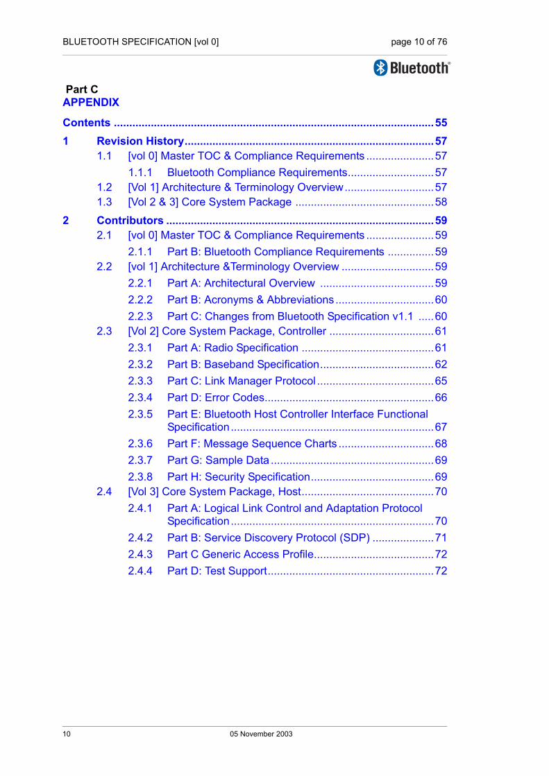
Part CAPPENDIX
Contents ........................................................................................................551 Revision History.................................................................................57
1.1 [vol 0] Master TOC & Compliance Requirements ......................571.1.1 Bluetooth Compliance Requirements............................57
1.2 [Vol 1] Architecture & Terminology Overview.............................571.3 [Vol 2 & 3] Core System Package .............................................58
2 Contributors .......................................................................................592.1 [vol 0] Master TOC & Compliance Requirements ......................59
2.1.1 Part B: Bluetooth Compliance Requirements ...............592.2 [vol 1] Architecture &Terminology Overview ..............................59
2.2.1 Part A: Architectural Overview .....................................592.2.2 Part B: Acronyms & Abbreviations ................................602.2.3 Part C: Changes from Bluetooth Specification v1.1 .....60
2.3 [Vol 2] Core System Package, Controller ..................................612.3.1 Part A: Radio Specification ...........................................612.3.2 Part B: Baseband Specification.....................................622.3.3 Part C: Link Manager Protocol ......................................652.3.4 Part D: Error Codes.......................................................662.3.5 Part E: Bluetooth Host Controller Interface Functional
Specification..................................................................672.3.6 Part F: Message Sequence Charts ...............................682.3.7 Part G: Sample Data .....................................................692.3.8 Part H: Security Specification........................................69
2.4 [Vol 3] Core System Package, Host...........................................702.4.1 Part A: Logical Link Control and Adaptation Protocol
Specification..................................................................702.4.2 Part B: Service Discovery Protocol (SDP) ....................712.4.3 Part C Generic Access Profile.......................................722.4.4 Part D: Test Support......................................................72
10 05 November 2003
BLUETOOTH SPECIFICATION [vol 0] page 11 of 76
Specification Volume 1Architecture & Terminology Overview
Table of Contents ...........................................................................................5
Part AARCHITECTURE
Contents ........................................................................................................111 General Description ...........................................................................13
1.1 Overview of Operation ...............................................................131.2 Nomenclature.............................................................................15
2 Core System Architecture .................................................................192.1 Core Architectural Blocks...........................................................22
2.1.1 Channel manager..........................................................222.1.2 L2CAP resource manager.............................................222.1.3 Device manager ............................................................232.1.4 Link manager.................................................................232.1.5 Baseband resource manager ........................................232.1.6 Link controller ................................................................242.1.7 RF..................................................................................24
3 Data Transport Architecture..............................................................253.1 Core Traffic Bearers...................................................................26
3.1.1 Framed data traffic ........................................................273.1.2 Unframed data traffic .....................................................283.1.3 Reliability of traffic bearers ............................................28
3.2 Transport Architecture Entities...................................................303.2.1 Bluetooth generic packet structure................................30
3.3 Physical Channels......................................................................323.3.1 Basic piconet channel ...................................................333.3.2 Adapted piconet channel...............................................343.3.3 Inquiry scan channel .....................................................353.3.4 Page scan channel........................................................36
3.4 Physical Links ............................................................................373.4.1 Links supported by the basic and adapted piconet physi-
cal channel ....................................................................383.4.2 Links supported by the scanning physical channels .....39
05 November 2003 11
BLUETOOTH SPECIFICATION [vol 0] page 12 of 76
3.5 Logical Links and Logical Transports.........................................393.5.1 Casting..........................................................................413.5.2 Scheduling and acknowledgement scheme..................413.5.3 Class of data .................................................................423.5.4 Asynchronous connection-oriented (ACL) ....................423.5.5 Synchronous connection-oriented (SCO) .....................433.5.6 Extended synchronous connection-oriented (eSCO)....443.5.7 Active slave broadcast (ASB)........................................443.5.8 Parked slave broadcast (PSB) ......................................453.5.9 Logical links ..................................................................463.5.10 ACL Control Logical Link (ACL-C) ................................473.5.11 User Asynchronous/Isochronous Logical Link (ACL-U) 473.5.12 User Synchronous/Extended Synchronous Logical Links
(SCO-S/eSCO-S) ..........................................................473.6 L2CAP Channels .......................................................................48
4 Communication Topology.................................................................494.1 Piconet Topology .......................................................................494.2 Operational Procedures and Modes ..........................................51
4.2.1 Inquiry (Discovering) Procedure....................................514.2.2 Paging (Connecting) Procedure....................................524.2.3 Connected mode...........................................................524.2.4 Hold mode.....................................................................534.2.5 Sniff mode .....................................................................534.2.6 Parked state ..................................................................544.2.7 Role switch procedure...................................................54
12 05 November 2003

BLUETOOTH SPECIFICATION [vol 0] page 13 of 76
Part BACRONYMS & ABBREVIATIONS
1 List of Acronyms and Abbreviations................................................572 Abbreviations of the Specification Names ......................................65
Part CCHANGES FROM BLUETOOTH SPECIFICATION V 1.1
Contents ........................................................................................................691 New Features......................................................................................712 Changes in Wording ..........................................................................73
2.1 IEEE Language Update .............................................................732.1.1 Shall ..............................................................................742.1.2 Must...............................................................................742.1.3 Will.................................................................................742.1.4 Should ...........................................................................742.1.5 May................................................................................752.1.6 Can................................................................................75
2.2 Nomenclature Changes .............................................................75
3 Structure Changes .............................................................................774 Deprecated Specifications ................................................................79
4.1 Deprecated Features .................................................................794.2 Deprecated Profiles....................................................................79
05 November 2003 13

BLUETOOTH SPECIFICATION [vol 0] page 14 of 76
Specification Volume 2Core System Package[Controller volume]
Table of Contents ...........................................................................................5
Part ARADIO SPECIFICATION
Contents ........................................................................................................271 Scope ..................................................................................................292 Frequency Bands and Channel Arrangement.................................313 Transmitter Characteristics ..............................................................33
3.1 Modulation Characteristics ........................................................343.2 Spurious Emissions ...................................................................35
3.2.1 In-band spurious emission ............................................353.3 Radio Frequency Tolerance.......................................................36
4 Receiver Characteristics ...................................................................374.1 Actual Sensitivity Level ..............................................................374.2 Interference Performance ..........................................................374.3 Out-of-Band Blocking.................................................................384.4 Intermodulation Characteristics .................................................384.5 Maximum Usable Level .............................................................394.6 Receiver Signal Strength Indicator ............................................394.7 Reference Signal Definition .......................................................39
5 Appendix A .........................................................................................416 Appendix B .........................................................................................43
14 05 November 2003

BLUETOOTH SPECIFICATION [vol 0] page 15 of 76
Part BBASEBAND SPECIFICATION
Contents ........................................................................................................471 General Description ...........................................................................53
1.1 Bluetooth Clock .........................................................................541.2 Bluetooth Device Addressing.....................................................55
1.2.1 Reserved addresses .....................................................551.3 Access Codes ............................................................................56
2 Physical Channels..............................................................................572.1 Physical Channel Definition .......................................................582.2 Basic Piconet Physical Channel.................................................58
2.2.1 Master-slave definition ..................................................582.2.2 Hopping characteristics ................................................592.2.3 Time slots ......................................................................592.2.4 Piconet clocks ...............................................................602.2.5 Transmit/receive timing .................................................60
2.3 Adapted Piconet Physical Channel ............................................632.3.1 Hopping characteristics .................................................63
2.4 Page Scan Physical Channel.....................................................642.4.1 Clock estimate for paging..............................................642.4.2 Hopping characteristics .................................................642.4.3 Paging procedure timing ...............................................652.4.4 Page response timing....................................................66
2.5 Inquiry Scan Physical Channel ..................................................682.5.1 Clock for inquiry.............................................................682.5.2 Hopping characteristics .................................................682.5.3 Inquiry procedure timing................................................682.5.4 Inquiry response timing .................................................68
2.6 Hop Selection.............................................................................702.6.1 General selection scheme.............................................702.6.2 Selection kernel ............................................................742.6.3 Adapted hop selection kernel .......................................772.6.4 Control word ..................................................................78
3 Physical Links ...................................................................................833.1 Link Supervision.........................................................................83
05 November 2003 15

BLUETOOTH SPECIFICATION [vol 0] page 16 of 76
4 Logical Transports .............................................................................854.1 General ......................................................................................854.2 Logical Transport Address (LT_ADDR) .....................................854.3 Synchronous Logical Transports ...............................................864.4 Asynchronous Logical Transport ...............................................864.5 Transmit/Receive Routines........................................................87
4.5.1 TX Routine ....................................................................874.5.2 RX routine .....................................................................904.5.3 Flow control...................................................................91
4.6 Active Slave Broadcast Transport..............................................924.7 Parked Slave Broadcast Transport ............................................93
4.7.1 Parked member address (PM_ADDR)..........................934.7.2 Access request address (AR_ADDR) ...........................93
5 Logical Links ......................................................................................955.1 Link Control Logical Link (LC)....................................................955.2 ACL Control Logical Link (ACL-C) .............................................955.3 User Asynchronous/Isochronous Logical Link (ACL-U).............95
5.3.1 Pausing the ACL-U logical link......................................965.4 User Synchronous Data Logical Link (SCO-S) .........................965.5 User Extended Synchronous Data Logical Link (eSCO-S) .......965.6 Logical Link Priorities.................................................................96
6 Packets................................................................................................976.1 General Format..........................................................................976.2 Bit Ordering................................................................................976.3 Access Code..............................................................................98
6.3.1 Access code types ........................................................986.3.2 Preamble.......................................................................996.3.3 Sync word .....................................................................996.3.4 Trailer ..........................................................................102
6.4 Packet Header .........................................................................1036.4.1 LT_ADDR....................................................................1036.4.2 TYPE...........................................................................1036.4.3 FLOW..........................................................................1046.4.4 ARQN..........................................................................1046.4.5 SEQN..........................................................................1046.4.6 HEC ............................................................................104
16 05 November 2003
BLUETOOTH SPECIFICATION [vol 0] page 17 of 76
6.5 Packet Types ...........................................................................1056.5.1 Common packet types.................................................1066.5.2 SCO packets ...............................................................1096.5.3 eSCO packets .............................................................1106.5.4 ACL packets ................................................................ 111
6.6 Payload Format........................................................................1126.6.1 Synchronous data field................................................1126.6.2 Asynchronous data field ..............................................113
6.7 Packet Summary......................................................................116
7 Bitstream Processing ......................................................................1177.1 Error Checking .........................................................................118
7.1.1 HEC generation...........................................................1187.1.2 CRC generation...........................................................119
7.2 Data Whitening.........................................................................1217.3 Error Correction........................................................................1227.4 FEC Code: Rate 1/3.................................................................1227.5 FEC Code: Rate 2/3.................................................................1237.6 ARQ Scheme ...........................................................................124
7.6.1 Unnumbered ARQ.......................................................1247.6.2 Retransmit filtering ......................................................1277.6.3 Flushing payloads .......................................................1307.6.4 Multi-slave considerations ...........................................1307.6.5 Broadcast packets.......................................................130
8 Link Controller Operation................................................................1338.1 Overview of States ...................................................................1338.2 Standby State ...........................................................................1348.3 Connection Establishment Substates ......................................134
8.3.1 Page scan substate.....................................................1348.3.2 Page substate .............................................................1368.3.3 Page response substates............................................139
8.4 Device Discovery Substates ....................................................1438.4.1 Inquiry scan substate ..................................................1448.4.2 Inquiry substate ...........................................................1458.4.3 Inquiry response substate ...........................................147
8.5 Connection State......................................................................148
05 November 2003 17

BLUETOOTH SPECIFICATION [vol 0] page 18 of 76
8.6 Active Mode .............................................................................1498.6.1 Polling in the active mode ..........................................1508.6.2 SCO ...........................................................................1508.6.3 eSCO .........................................................................1518.6.4 Broadcast scheme .....................................................1548.6.5 Role switch..................................................................1558.6.6 Scatternet....................................................................1578.6.7 Hop sequence switching .............................................1588.6.8 Channel classification and channel map selection ....1618.6.9 Power Management ....................................................162
8.7 Sniff Mode................................................................................1638.7.1 Sniff Transition Mode .................................................164
8.8 Hold Mode ...............................................................................1658.9 Park State ................................................................................165
8.9.1 Beacon train ................................................................1668.9.2 Beacon access window...............................................1688.9.3 Parked slave synchronization .....................................1698.9.4 Parking........................................................................1708.9.5 Master-initiated unparking...........................................1718.9.6 Slave-initiated unparking.............................................1718.9.7 Broadcast scan window ..............................................1728.9.8 Polling in the park state...............................................172
9 Audio.................................................................................................1739.1 LOG PCM CODEC ..................................................................1739.2 CVSD CODEC.........................................................................1739.3 Error Handling..........................................................................1769.4 General Audio Requirements...................................................176
9.4.1 Signal levels ................................................................1769.4.2 CVSD audio quality .....................................................176
10 List of Figures ..................................................................................17711 List of Tables ....................................................................................181
Appendix A: General Audio Recommendations ...........................................................182
Appendix B: Timers .........................................................................................................185
Appendix C: Recommendations for AFH Operation in Park, Hold and Sniff ............187
18 05 November 2003

BLUETOOTH SPECIFICATION [vol 0] page 19 of 76
Part CLINK MANAGER PROTOCOL
Contents ......................................................................................................1911 Introduction ......................................................................................1952 General Rules ...................................................................................197
2.1 Message Transport ..................................................................1972.2 Synchronization .......................................................................1972.3 Packet Format..........................................................................1982.4 Transactions.............................................................................199
2.4.1 LMP Response Timeout ..............................................2002.5 Error Handling..........................................................................200
2.5.1 Transaction collision resolution ...................................2012.6 Procedure Rules ......................................................................2012.7 General Response Messages..................................................2022.8 LMP Message Constraints .......................................................202
3 Device Features................................................................................2033.1 General Description .................................................................2033.2 Feature Definitions...................................................................2033.3 Feature Mask Definition ...........................................................2073.4 Link Manager Interoperability policy.........................................208
4 Procedure Rules...............................................................................2094.1 Connection Control ..................................................................209
4.1.1 Connection establishment ...........................................2094.1.2 Detach .........................................................................2104.1.3 Power control ..............................................................2114.1.4 Adaptive frequency hopping........................................2134.1.5 Channel classification..................................................2164.1.6 Link supervision...........................................................2184.1.7 Channel quality driven data rate change (CQDDR) ....2194.1.8 Quality of service (QoS) ..............................................2204.1.9 Paging scheme parameters ........................................2224.1.10 Control of multi-slot packets ........................................223
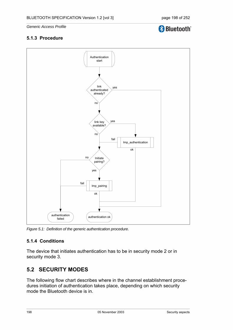
4.2 Security ....................................................................................2244.2.1 Authentication..............................................................2244.2.2 Pairing .........................................................................2264.2.3 Change link key...........................................................2294.2.4 Change current link key type.......................................2304.2.5 Encryption ...................................................................2324.2.6 Request supported encryption key size ......................236
05 November 2003 19

BLUETOOTH SPECIFICATION [vol 0] page 20 of 76
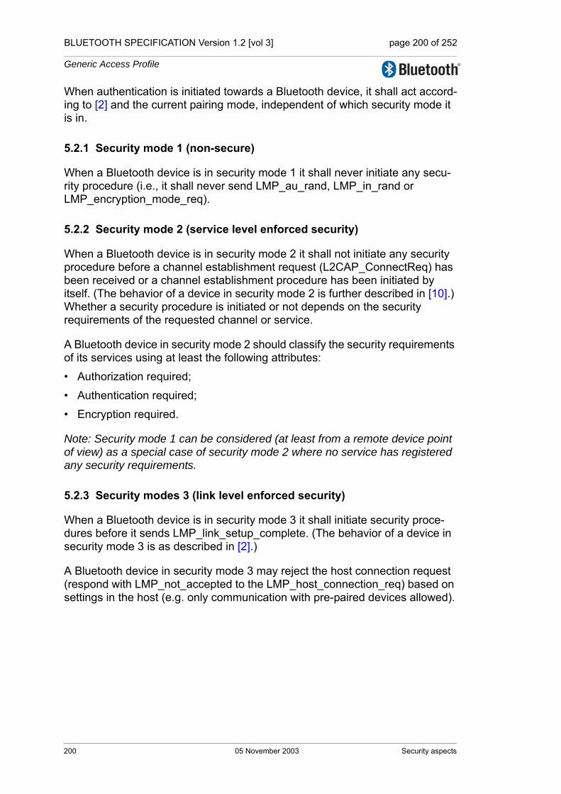
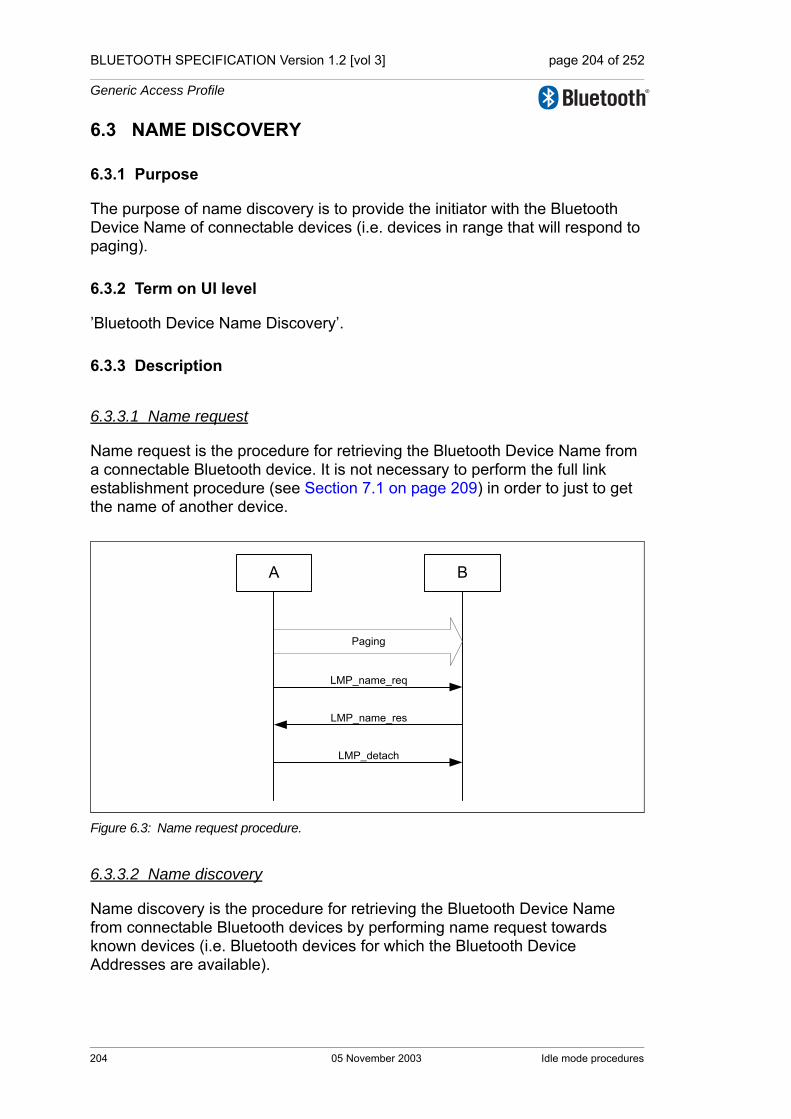
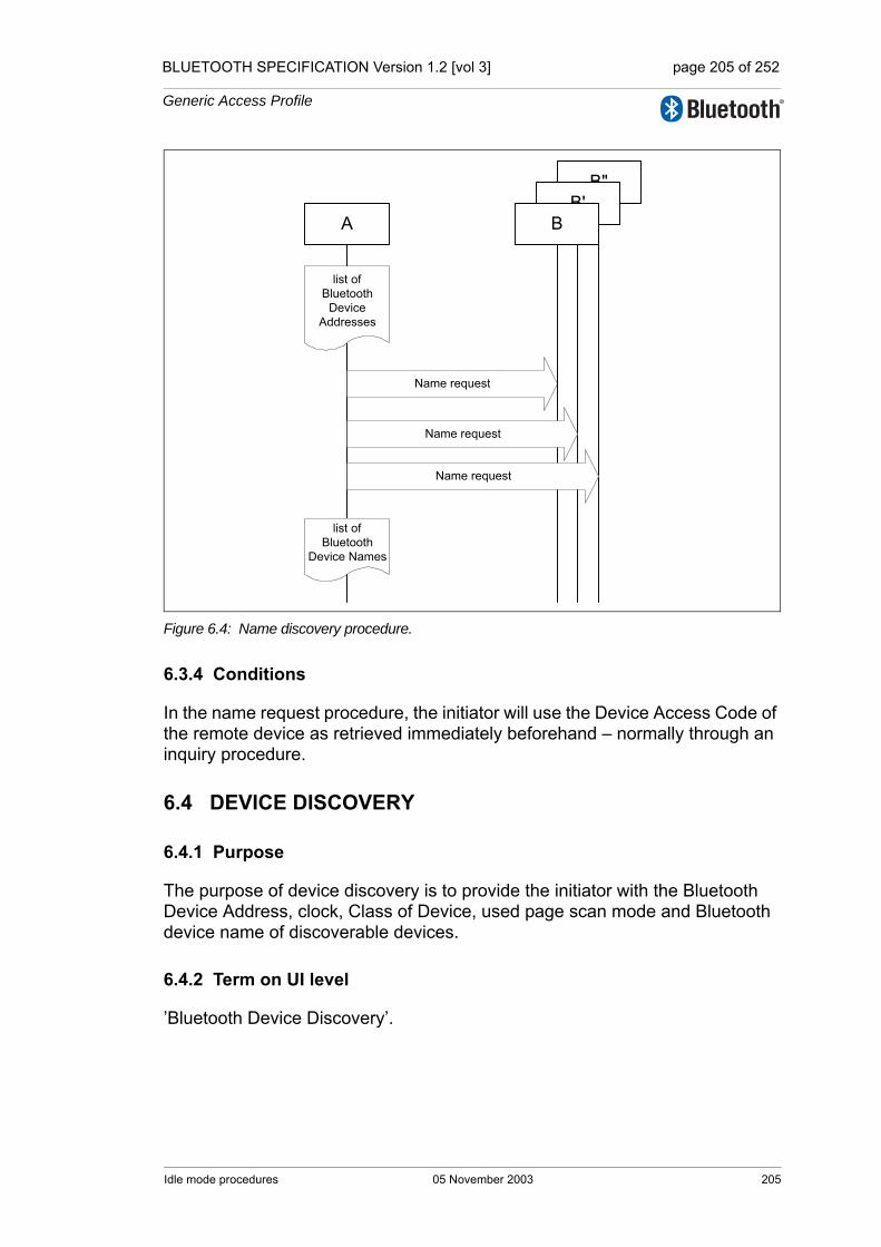
4.3 Informational Requests ............................................................2374.3.1 Timing accuracy ..........................................................2374.3.2 Clock offset .................................................................2384.3.3 LMP version ................................................................2384.3.4 Supported features .....................................................2394.3.5 Name request .............................................................241
4.4 Role Switch..............................................................................2424.4.1 Slot offset ....................................................................2424.4.2 Role switch..................................................................243
4.5 Modes of Operation .................................................................2454.5.1 Hold mode...................................................................2454.5.2 Park state ....................................................................2474.5.3 Sniff mode ...................................................................253
4.6 Logical Transports ...................................................................2564.6.1 SCO logical transport ..................................................2564.6.2 eSCO logical transport ................................................259
4.7 Test Mode ................................................................................2644.7.1 Activation and deactivation of test mode.....................2644.7.2 Control of test mode....................................................2654.7.3 Summary of test mode PDUs......................................266
5 Summary...........................................................................................2695.1 PDU Summary ........................................................................2695.2 Parameter Definitions .............................................................2775.3 Default Values..........................................................................284
6 List of Figures ..................................................................................2857 List of Tables ....................................................................................289
20 05 November 2003

BLUETOOTH SPECIFICATION [vol 0] page 21 of 76
Part DERROR CODES
Contents ......................................................................................................2931 Overview of Error Codes .................................................................295
1.1 Usage Descriptions..................................................................2951.2 HCI Command Errors...............................................................2951.3 List of Error Codes ...................................................................296
2 Error Code Descriptions..................................................................2992.1 Unknown HCI Command (0X01)..............................................2992.2 Unknown Connection Identifier (0X02) ....................................2992.3 Hardware Failure (0X03)..........................................................2992.4 Page Timeout (0X04) ...............................................................2992.5 Authentication Failure (0X05)...................................................2992.6 PIN Missing (0X06) ..................................................................2992.7 Memory Capacity Exceeded (0X07) ........................................2992.8 Connection Timeout (0X08) .....................................................3002.9 Connection Limit Exceeded (0X09)..........................................3002.10 Synchronous Connection Limit to a Device Exceeded (0X0A) 3002.11 ACL Connection Already Exists (0X0B) ...................................3002.12 Command Disallowed (0X0C)..................................................3002.13 Connection Rejected due to Limited Resources (0X0D)..........3002.14 Connection Rejected due to Security Reasons (0X0E) ...........3002.15 Connection Rejected due to Unacceptable BD_ADDR (0X0F)3012.16 Connection Accept Timeout Exceeded (0X10) ........................3012.17 Unsupported Feature or Parameter Value (0X11)....................3012.18 Invalid HCI Command Parameters (0X12)...............................3012.19 Remote User Terminated Connection (0X13) ..........................3012.20 Remote Device Terminated Connection due to Low Resources
(0X14) ......................................................................................3022.21 Remote Device Terminated Connection due to Power Off
(0X15) ......................................................................................3022.22 Connection Terminated by Local Host (0X16)..........................3022.23 Repeated Attempts (0X17).......................................................3022.24 Pairing not Allowed (0X18).......................................................3022.25 Unknown LMP PDU (0X19) .....................................................3022.26 Unsupported Remote Feature (0X1A) .....................................3022.27 SCO Offset Rejected (0X1B) ...................................................3022.28 SCO Interval Rejected (0X1C) .................................................3032.29 SCO Air Mode Rejected (0X1D) ..............................................3032.30 Invalid LMP Parameters (0X1E)...............................................3032.31 Unspecified Error (0X1F) .........................................................3032.32 Unsupported LMP Parameter Value (0X20).............................303
05 November 2003 21

BLUETOOTH SPECIFICATION [vol 0] page 22 of 76
2.33 Role Change Not Allowed (0X21)............................................3032.34 LMP Response Timeout (0X22)...............................................3032.35 LMP Error Transaction Collision (0X23) ..................................3042.36 LMP PDU Not Allowed (0X24).................................................3042.37 Encryption Mode Not Acceptable (0X25).................................3042.38 Link Key Can Not be Changed (0X26) ....................................3042.39 Requested Qos Not Supported (0X27)....................................3042.40 Instant Passed (0X28) .............................................................3042.41 Pairing with Unit Key Not Supported (0X29)............................3042.42 Different Transaction Collision (0x2a)......................................3042.43 QoS Unacceptable Parameter (0X2C).....................................3042.44 QoS Rejected (0X2D) ..............................................................3052.45 Channel Classification Not Supported (0X2E).........................3052.46 Insufficient Security (0X2F)......................................................3052.47 Parameter out of Mandatory Range (0X30).............................3052.48 Role Switch Pending (0X32)....................................................3052.49 Reserved Slot Violation (0X34)................................................3052.50 Role Switch Failed (0X35) .......................................................305
22 05 November 2003

BLUETOOTH SPECIFICATION [vol 0] page 23 of 76
Part EHOST CONTROLLER INTERFACE FUNCTIONAL SPECIFICATION
Contents ......................................................................................................3091 Introduction ......................................................................................317
1.1 Lower Layers of the Bluetooth Software Stack ........................317
2 Overview of Host Controller Transport Layer................................3193 Overview of Commands and Events ..............................................321
3.1 Generic Events.........................................................................3223.2 Device Setup............................................................................3223.3 Controller Flow Control ............................................................3233.4 Controller Information...............................................................3233.5 Controller Configuration ...........................................................3243.6 Device Discovery .....................................................................3253.7 Connection Setup ....................................................................3273.8 Remote Information..................................................................3293.9 Synchronous Connections .......................................................3303.10 Connection State......................................................................3313.11 Piconet Structure......................................................................3323.12 Quality of Service.....................................................................3333.13 Physical Links ..........................................................................3343.14 Host Flow Control.....................................................................3353.15 Link Information .......................................................................3363.16 Authentication and Encryption .................................................3373.17 Testing......................................................................................3393.18 Alphabetical List of Commands and Events ............................340
4 HCI Flow Control ..............................................................................3454.1 Host to Controller Data Flow Control .......................................3454.2 Controller to Host Data Flow Control .......................................3464.3 Disconnection Behaviour .........................................................3474.4 Command Flow Control ...........................................................3474.5 Command Error Handling ........................................................348
5 HCI Data Formats .............................................................................3495.1 Introduction ..............................................................................3495.2 Data and Parameter Formats...................................................3495.3 Connection Handles.................................................................3505.4 Exchange of HCI-Specific Information .....................................351
5.4.1 HCI Command Packet.................................................3515.4.2 HCI ACL Data Packets................................................3535.4.3 HCI Synchronous Data Packets..................................3555.4.4 HCI Event Packet ........................................................356
05 November 2003 23
BLUETOOTH SPECIFICATION [vol 0] page 24 of 76
6 HCI Configuration Parameters........................................................3576.1 Scan Enable ............................................................................3576.2 Inquiry Scan Interval ................................................................3576.3 Inquiry Scan Window ...............................................................3586.4 Inquiry Scan Type ....................................................................3586.5 Inquiry Mode ............................................................................3586.6 Page Timeout...........................................................................3596.7 Connection Accept Timeout.....................................................3596.8 Page Scan Interval ..................................................................3606.9 Page Scan Window .................................................................3606.10 Page Scan Period Mode..........................................................3606.11 Page Scan Type ......................................................................3616.12 Voice Setting............................................................................3616.13 PIN Type ..................................................................................3626.14 Link Key ...................................................................................3626.15 Authentication Enable..............................................................3626.16 Encryption Mode......................................................................3636.17 Failed Contact Counter ............................................................3646.18 Hold Mode Activity ...................................................................3646.19 Link Policy Settings..................................................................3656.20 Flush Timeout ..........................................................................3666.21 Num Broadcast Retransmissions ............................................3666.22 Link Supervision Timeout.........................................................3676.23 Synchronous Flow Control Enable ..........................................3676.24 Local Name..............................................................................3686.25 Class Of Device .......................................................................3686.26 Supported Commands.............................................................369
7 HCI Commands and Events ............................................................3737.1 Link Control Commands ..........................................................373
7.1.1 Inquiry Command........................................................3737.1.2 Inquiry Cancel Command............................................3757.1.3 Periodic Inquiry Mode Command................................3767.1.4 Exit Periodic Inquiry Mode Command.........................3797.1.5 Create Connection Command.....................................3807.1.6 Disconnect Command.................................................3837.1.7 Create Connection Cancel Command ........................3847.1.8 Accept Connection Request Command......................3867.1.9 Reject Connection Request Command.......................3887.1.10 Link Key Request Reply Command ............................3897.1.11 Link Key Request Negative Reply Command.............3917.1.12 PIN Code Request Reply Command ..........................392
24 05 November 2003

BLUETOOTH SPECIFICATION [vol 0] page 25 of 76
7.1.13 PIN Code Request Negative Reply Command ...........3947.1.14 Change Connection Packet Type Command ..............3957.1.15 Authentication Requested Command..........................3987.1.16 Set Connection Encryption Command ........................3997.1.17 Change Connection Link Key Command ....................4007.1.18 Master Link Key Command.........................................4017.1.19 Remote Name Request Command .............................4027.1.20 Remote Name Request Cancel Command.................4047.1.21 Read Remote Supported Features Command............4057.1.22 Read Remote Extended Features Command ............4067.1.23 Read Remote Version Information Command.............4077.1.24 Read Clock Offset Command......................................4087.1.25 Read LMP Handle Command ....................................4097.1.26 Setup Synchronous Connection Command ...............4117.1.27 Accept Synchronous Connection Request Command 4157.1.28 Reject Synchronous Connection Request Command.419
7.2 Link Policy Commands.............................................................4207.2.1 Hold Mode Command .................................................4207.2.2 Sniff Mode Command..................................................4227.2.3 Exit Sniff Mode Command...........................................4257.2.4 Park State Command ..................................................4267.2.5 Exit Park State Command ...........................................4287.2.6 QoS Setup Command .................................................4297.2.7 Role Discovery Command...........................................4317.2.8 Switch Role Command................................................4327.2.9 Read Link Policy Settings Command ..........................4337.2.10 Write Link Policy Settings Command ..........................4347.2.11 Read Default Link Policy Settings Command .............4367.2.12 Write Default Link Policy Settings Command .............4377.2.13 Flow Specification Command .....................................438
7.3 Controller & Baseband Commands..........................................4407.3.1 Set Event Mask Command..........................................4407.3.2 Reset Command .........................................................4427.3.3 Set Event Filter Command ..........................................4437.3.4 Flush Command..........................................................4487.3.5 Read PIN Type Command ..........................................4507.3.6 Write PIN Type Command...........................................4517.3.7 Create New Unit Key Command .................................452
05 November 2003 25

BLUETOOTH SPECIFICATION [vol 0] page 26 of 76
7.3.8 Read Stored Link Key Command................................4537.3.9 Write Stored Link Key Command................................4547.3.10 Delete Stored Link Key Command..............................4567.3.11 Write Local Name Command ......................................4577.3.12 Read Local Name Command......................................4587.3.13 Read Connection Accept Timeout Command.............4597.3.14 Write Connection Accept Timeout Command .............4607.3.15 Read Page Timeout Command...................................4617.3.16 Write Page Timeout Command...................................4627.3.17 Read Scan Enable Command.....................................4637.3.18 Write Scan Enable Command.....................................4647.3.19 Read Page Scan Activity Command...........................4657.3.20 Write Page Scan Activity Command ...........................4677.3.21 Read Inquiry Scan Activity Command.........................4687.3.22 Write Inquiry Scan Activity Command.........................4697.3.23 Read Authentication Enable Command......................4707.3.24 Write Authentication Enable Command ......................4717.3.25 Read Encryption Mode Command..............................4727.3.26 Write Encryption Mode Command ..............................4737.3.27 Read Class of Device Command................................4747.3.28 Write Class of Device Command ................................4757.3.29 Read Voice Setting Command....................................4767.3.30 Write Voice Setting Command ....................................4777.3.31 Read Automatic Flush Timeout Command .................4787.3.32 Write Automatic Flush Timeout Command..................4797.3.33 Read Num Broadcast Retransmissions Command.....4807.3.34 Write Num Broadcast Retransmissions Command.....4817.3.35 Read Hold Mode Activity Command ...........................4827.3.36 Write Hold Mode Activity Command ...........................4837.3.37 Read Transmit Power Level Command ......................4847.3.38 Read Synchronous Flow Control Enable Command...4867.3.39 Write Synchronous Flow Control Enable Command...4877.3.40 Set Controller To Host Flow Control Command ..........4887.3.41 Host Buffer Size Command.........................................4897.3.42 Host Number Of Completed Packets Command ........4917.3.43 Read Link Supervision Timeout Command.................4937.3.44 Write Link Supervision Timeout Command.................4947.3.45 Read Number Of Supported IAC Command...............496
26 05 November 2003

BLUETOOTH SPECIFICATION [vol 0] page 27 of 76
7.3.46 Read Current IAC LAP Command ..............................4977.3.47 Write Current IAC LAP Command...............................4987.3.48 Read Page Scan Period Mode Command ..................5007.3.49 Write Page Scan Period Mode Command ..................5017.3.50 Set AFH Host Channel Classification Command .......5027.3.51 Read Inquiry Scan Type Command ...........................5037.3.52 Write Inquiry Scan Type Command ............................5047.3.53 Read Inquiry Mode Command ...................................5057.3.54 Write Inquiry Mode Command ....................................5067.3.55 Read Page Scan Type Command ..............................5077.3.56 Write Page Scan Type Command ..............................5087.3.57 Read AFH Channel Assessment Mode Command ....5097.3.58 Write AFH Channel Assessment Mode Command ....510
7.4 Informational Parameters.........................................................5127.4.1 Read Local Version Information Command.................5127.4.2 Read Local Supported Commands Command............5147.4.3 Read Local Supported Features Command................5157.4.4 Read Local Extended Features Command ................5167.4.5 Read Buffer Size Command........................................5187.4.6 Read BD_ADDR Command........................................520
7.5 Status Parameters....................................................................5217.5.1 Read Failed Contact Counter Command ....................5217.5.2 Reset Failed Contact Counter Command ...................5237.5.3 Read Link Quality Command ......................................5247.5.4 Read RSSI Command.................................................5257.5.5 Read AFH Channel Map Command ...........................5277.5.6 Read Clock Command ...............................................529
7.6 Testing Commands ..................................................................5317.6.1 Read Loopback Mode Command ...............................5317.6.2 Write Loopback Mode Command................................5327.6.3 Enable Device Under Test Mode Command ...............535
7.7 Events ......................................................................................5377.7.1 Inquiry Complete Event ...............................................5377.7.2 Inquiry Result Event ....................................................5387.7.3 Connection Complete Event........................................5407.7.4 Connection Request Event..........................................5417.7.5 Disconnection Complete Event ...................................5437.7.6 Authentication Complete Event ...................................544
05 November 2003 27

BLUETOOTH SPECIFICATION [vol 0] page 28 of 76
7.7.7 Remote Name Request Complete Event ....................5457.7.8 Encryption Change Event ...........................................5467.7.9 Change Connection Link Key Complete Event ...........5477.7.10 Master Link Key Complete Event................................5487.7.11 Read Remote Supported Features Complete Event...5497.7.12 Read Remote Version Information Complete Event ...5507.7.13 QoS Setup Complete Event ........................................5517.7.14 Command Complete Event .........................................5537.7.15 Command Status Event ..............................................5547.7.16 Hardware Error Event .................................................5557.7.17 Flush Occurred Event .................................................5557.7.18 Role Change Event .....................................................5567.7.19 Number Of Completed Packets Event ........................5577.7.20 Mode Change Event ...................................................5587.7.21 Return Link Keys Event...............................................5607.7.22 PIN Code Request Event ............................................5617.7.23 Link Key Request Event..............................................5627.7.24 Link Key Notification Event .........................................5637.7.25 Loopback Command Event.........................................5647.7.26 Data Buffer Overflow Event.........................................5647.7.27 Max Slots Change Event.............................................5657.7.28 Read Clock Offset Complete Event ............................5667.7.29 Connection Packet Type Changed Event ...................5677.7.30 QoS Violation Event ....................................................5697.7.31 Page Scan Repetition Mode Change Event................5707.7.32 Flow Specification Complete Event.............................5717.7.33 Inquiry Result with RSSI Event ..................................5737.7.34 Read Remote Extended Features Complete Event ....5757.7.35 Synchronous Connection Complete Event .................5767.7.36 Synchronous Connection Changed event...................578
8 List of Figures ..................................................................................5819 List of Tables ....................................................................................583
Appendix A: Deprecated Commands, Events and Configuration Parameters ...........585
28 05 November 2003
BLUETOOTH SPECIFICATION [vol 0] page 29 of 76
Part FMESSAGE SEQUENCE CHARTS
Contents ......................................................................................................5951 Introduction ......................................................................................599
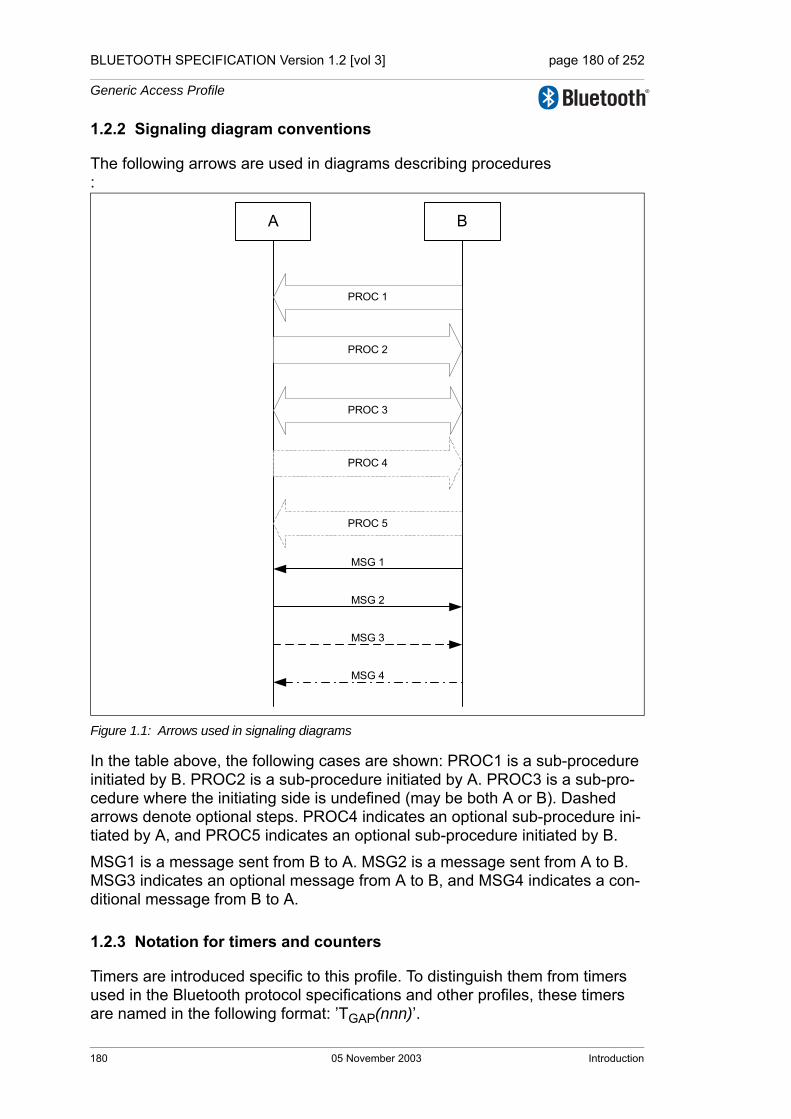
1.1 Notation....................................................................................5991.2 Flow of Control .........................................................................6001.3 Example MSC ..........................................................................600
2 Services Without Connection Request ..........................................6012.1 Remote Name Request............................................................6012.2 One-time Inquiry.......................................................................6022.3 Periodic Inquiry ........................................................................604
3 ACL Connection Establishment and Detachment.........................6073.1 Connection Setup ....................................................................608
4 Optional Activities After ACL Connection Establishment............6154.1 Authentication Requested........................................................6154.2 Set Connection Encryption.......................................................6164.3 Change Connection Link Key...................................................6174.4 Master Link Key .......................................................................6184.5 Read Remote Supported Features ..........................................6204.6 Read Remote Extended Features ...........................................6204.7 Read Clock Offset ....................................................................6214.8 Read Remote Version Information...........................................6214.9 QOS Setup...............................................................................6224.10 Switch Role ..............................................................................622
5 Synchronous Connection Establishment and Detachment .........6255.1 Synchronous Connection Setup...............................................625
6 Sniff, Hold and Park .........................................................................6316.1 Sniff Mode ................................................................................6316.2 Hold Mode................................................................................6326.3 Park State.................................................................................634
7 Buffer Management, Flow Control..................................................6378 Loopback Mode................................................................................639
8.1 Local Loopback Mode..............................................................6398.2 Remote Loopback Mode..........................................................641
9 List of Figures...................................................................................643
05 November 2003 29

BLUETOOTH SPECIFICATION [vol 0] page 30 of 76
Part GSAMPLE DATA
Contents ......................................................................................................6471 Encryption Sample Data..................................................................649
1.1 Generating Kc' from Kc,...........................................................6491.2 First Set of Sample Data..........................................................6521.3 Second Set of Sample Data.....................................................6601.4 Third Set of Samples ...............................................................6681.5 Fourth Set of Samples .............................................................676
2 Frequency Hopping Sample Data...................................................6852.1 First set ....................................................................................6862.2 Second set...............................................................................6922.3 Third set...................................................................................698
3 Access Code Sample Data ..............................................................7054 HEC and Packet Header Sample Data............................................7095 CRC Sample Data............................................................................. 7116 Complete Sample Packets ..............................................................713
6.1 Example of DH1 Packet...........................................................7136.2 Example of DM1 Packet ..........................................................714
7 Whitening Sequence Sample Data .................................................7158 FEC Sample Data .............................................................................7199 Encryption Key Sample Data ..........................................................721
9.1 Four Tests of E1.......................................................................7219.2 Four Tests of E21.....................................................................7269.3 Three Tests of E22...................................................................7289.4 Tests of E22 With Pin Augmenting...........................................7309.5 Four Tests of E3.......................................................................740
30 05 November 2003

BLUETOOTH SPECIFICATION [vol 0] page 31 of 76
Part HSECURITY SPECIFICATION
Contents ......................................................................................................7471 Security Overview ............................................................................7492 Random Number Generation ..........................................................7513 Key Management..............................................................................753
3.1 Key Types ................................................................................7533.2 Key Generation and Initialization .............................................755
3.2.1 Generation of initialization key, ...................................7563.2.2 Authentication..............................................................7563.2.3 Generation of a unit key ..............................................7563.2.4 Generation of a combination key.................................7573.2.5 Generating the encryption key ....................................7583.2.6 Point-to-multipoint configuration..................................7593.2.7 Modifying the link keys ................................................7603.2.8 Generating a master key .............................................760
4 Encryption.........................................................................................7634.1 Encryption Key Size Negotiation..............................................7644.2 Encryption of Broadcast Messages..........................................7644.3 Encryption Concept..................................................................7654.4 Encryption Algorithm................................................................766
4.4.1 The operation of the cipher .........................................7684.5 LFSR Initialization ....................................................................7694.6 Key Stream Sequence .............................................................772
5 Authentication ..................................................................................7735.1 Repeated Attempts ..................................................................775
6 The Authentication And Key-Generating Functions.....................7776.1 The Authentication Function E1...............................................7776.2 The Functions Ar and A’r..........................................................779
6.2.1 The round computations..............................................7796.2.2 The substitution boxes “e” and “l”................................7796.2.3 Key scheduling ............................................................780
6.3 E2-Key Generation Function for Authentication.......................7816.4 E3-Key Generation Function for Encryption.............................783
7 List of Figures...................................................................................7858 List of Tables ....................................................................................787
05 November 2003 31

BLUETOOTH SPECIFICATION [vol 0] page 32 of 76
Specification Volume 3Core System Package[Host volume]
Table of Contents ...........................................................................................5
Part ALOGICAL LINK CONTROL AND ADAPTATION PROTOCOL SPECIFICATION
Contents ........................................................................................................171 Introduction ........................................................................................21
1.1 L2CAP Features ........................................................................211.2 Assumptions ..............................................................................251.3 Scope.........................................................................................251.4 Terminology ...............................................................................26
2 General Operation..............................................................................292.1 Channel Identifiers.....................................................................292.2 Operation Between Devices ......................................................292.3 Operation Between Layers ........................................................312.4 Modes of Operation ...................................................................31
3 Data Packet Format............................................................................333.1 Connection-oriented Channel in Basic L2CAP Mode ................333.2 Connectionless Data Channel in Basic L2CAP Mode ...............343.3 Connection-oriented Channel in Retransmission/Flow Control
Modes .......................................................................................353.3.1 L2CAP header fields .....................................................353.3.2 Control field (2 octets) ...................................................363.3.3 L2CAP SDU length field (2 octets)................................383.3.4 Information payload field (0 to 65531 octets) ................383.3.5 Frame check sequence (2 octets).................................393.3.6 Invalid frame detection ..................................................40
4 Signalling Packet Formats ................................................................414.1 Command Reject (code 0x01) ...................................................434.2 Connection Request (code 0x02) ..............................................444.3 Connection Response (code 0x03) ...........................................464.4 Configuration Request (code 0x04) ...........................................474.5 Configuration Response (code 0x05) ........................................504.6 Disconnection Request (code 0x06)..........................................524.7 Disconnection Response (code 0x07) .......................................534.8 Echo Request (code 0x08) ........................................................534.9 Echo Response (code 0x09) .....................................................54
32 05 November 2003
BLUETOOTH SPECIFICATION [vol 0] page 33 of 76
4.10 Information Request (code 0x0A) ..............................................544.11 Information Response (code 0x0B)............................................554.12 Extended Feature Mask.............................................................56
5 Configuration Parameter Options.....................................................575.1 Maximum Transmission Unit (MTU)...........................................575.2 Flush Timeout Option.................................................................595.3 Quality of Service (QoS) Option.................................................605.4 Retransmission and Flow Control Option...................................64
6 State Machine .....................................................................................676.1 General rules for the state machine: ..........................................67
6.1.1 CLOSED state ..............................................................686.1.2 WAIT_CONNECT_RSP state .......................................696.1.3 WAIT_CONNECT state ................................................696.1.4 CONFIG state................................................................706.1.5 OPEN state ..................................................................736.1.6 WAIT_DISCONNECT state ..........................................73
6.2 Timers events.............................................................................746.2.1 RTX ...............................................................................746.2.2 ERTX.............................................................................75
7 General Procedures ...........................................................................797.1 Configuration Process................................................................79
7.1.1 Request path .................................................................807.1.2 Response path ..............................................................80
7.2 Fragmentation and Recombination ............................................817.2.1 Fragmentation of L2CAP PDUs ....................................817.2.2 Recombination of L2CAP PDUs....................................82
7.3 Encapsulation of SDUs ..............................................................837.3.1 Segmentation of L2CAP SDUs .....................................837.3.2 Reassembly of L2CAP SDUs........................................847.3.3 Segmentation and fragmentation ..................................84
7.4 Delivery of Erroneous L2CAP SDUs..........................................857.5 Operation with Flushing .............................................................857.6 Connectionless Data Channel....................................................86
05 November 2003 33

BLUETOOTH SPECIFICATION [vol 0] page 34 of 76
8 Procedures for Flow Control and Retransmission .........................878.1 Information Retrieval..................................................................878.2 Function of PDU Types for Flow Control and Retransmission...87
8.2.1 Information frame (I-frame) ...........................................878.2.2 Supervisory Frame (S-frame)........................................87
8.3 Variables and Sequence Numbers ............................................898.3.1 Sending peer.................................................................898.3.2 Receiving peer ..............................................................91
8.4 Retransmission Mode ................................................................938.4.1 Transmitting frames ......................................................938.4.2 Receiving I-frames ........................................................958.4.3 I-frames pulled by the SDU reassembly function ..........958.4.4 Sending and receiving acknowledgements...................968.4.5 Receiving REJ frames...................................................978.4.6 Waiting acknowledgements ..........................................978.4.7 Exception conditions .....................................................97
8.5 Flow Control Mode.....................................................................998.5.1 Transmitting I-frames ....................................................998.5.2 Receiving I-frames ......................................................1008.5.3 I-frames pulled by the SDU reassembly function ........1008.5.4 Sending and receiving acknowledgements.................1008.5.5 Waiting acknowledgements ........................................1018.5.6 Exception conditions ...................................................101
9 List of Figures ..................................................................................10310 List of Tables ....................................................................................105
Appendix A: Configuration MSCs ...................................................................................107
34 05 November 2003

BLUETOOTH SPECIFICATION [vol 0] page 35 of 76
Part BSERVICE DISCOVERY PROTOCOL (SDP)
Contents ......................................................................................................1131 Introduction ......................................................................................115
1.1 General Description .................................................................1151.2 Motivation.................................................................................1151.3 Requirements...........................................................................1151.4 Non-requirements and Deferred Requirements .......................1161.5 Conventions .............................................................................116
1.5.1 Bit And Byte Ordering Conventions.............................116
2 Overview ...........................................................................................1172.1 SDP Client-Server Interaction..................................................1172.2 Service Record.........................................................................1182.3 Service Attribute.......................................................................1202.4 Attribute ID ...............................................................................1202.5 Attribute Value..........................................................................1212.6 Service Class ...........................................................................121
2.6.1 A Printer Service Class Example ................................1222.7 Searching for Services.............................................................123
2.7.1 UUID............................................................................1232.7.2 Service Search Patterns..............................................124
2.8 Browsing for Services ..............................................................1242.8.1 Example Service Browsing Hierarchy .........................125
3 Data Representation.........................................................................1273.1 Data Element ...........................................................................1273.2 Data Element Type Descriptor .................................................1273.3 Data Element Size Descriptor ..................................................1283.4 Data Element Examples...........................................................129
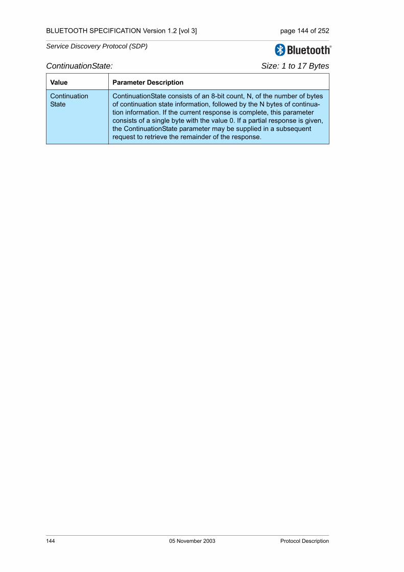
4 Protocol Description........................................................................1314.1 Transfer Byte Order .................................................................1314.2 Protocol Data Unit Format........................................................1314.3 Partial Responses and Continuation State...............................1334.4 Error Handling..........................................................................133
4.4.1 SDP_ErrorResponse PDU ..........................................1344.5 ServiceSearch Transaction ......................................................135
4.5.1 SDP_ServiceSearchRequest PDU..............................1354.5.2 SDP_ServiceSearchResponse PDU...........................136
4.6 ServiceAttribute Transaction ....................................................1384.6.1 SDP_ServiceAttributeRequest PDU............................1384.6.2 SDP_ServiceAttributeResponse PDU.........................140
05 November 2003 35

BLUETOOTH SPECIFICATION [vol 0] page 36 of 76
4.7 ServiceSearchAttribute Transaction ........................................1414.7.1 SDP_ServiceSearchAttributeRequest PDU................1414.7.2 SDP_ServiceSearchAttributeResponse PDU .............143
5 Service Attribute Definitions...........................................................1455.1 Universal Attribute Definitions..................................................145
5.1.1 ServiceRecordHandle Attribute...................................1455.1.2 ServiceClassIDList Attribute........................................1465.1.3 ServiceRecordState Attribute ......................................1465.1.4 ServiceID Attribute ......................................................1465.1.5 ProtocolDescriptorList Attribute...................................1475.1.6 BrowseGroupList Attribute ..........................................1485.1.7 LanguageBaseAttributeIDList Attribute .......................1485.1.8 ServiceInfoTimeToLive Attribute .................................1495.1.9 ServiceAvailability Attribute.........................................1505.1.10 BluetoothProfileDescriptorList Attribute ......................1505.1.11 DocumentationURL Attribute ......................................1515.1.12 ClientExecutableURL Attribute....................................1515.1.13 IconURL Attribute........................................................1525.1.14 ServiceName Attribute ................................................1525.1.15 ServiceDescription Attribute........................................1535.1.16 ProviderName Attribute...............................................1535.1.17 Reserved Universal Attribute IDs ................................153
5.2 ServiceDiscoveryServer Service Class Attribute Definitions ...1545.2.1 ServiceRecordHandle Attribute...................................1545.2.2 ServiceClassIDList Attribute........................................1545.2.3 VersionNumberList Attribute .......................................1545.2.4 ServiceDatabaseState Attribute ..................................1555.2.5 Reserved Attribute IDs ................................................155
5.3 BrowseGroupDescriptor Service Class Attribute Definitions ...1555.3.1 ServiceClassIDList Attribute........................................1555.3.2 GroupID Attribute ........................................................1565.3.3 Reserved Attribute IDs ................................................156
Appendix A:Background Information ...........................................................................157
Appendix B: Example SDP Transactions .......................................................................158
36 05 November 2003

BLUETOOTH SPECIFICATION [vol 0] page 37 of 76
Part CGENERIC ACCESS PROFILE
Contents ......................................................................................................173Foreword .....................................................................................................1771 Introduction ......................................................................................179
1.1 Scope.......................................................................................1791.2 Symbols and conventions ........................................................179
1.2.1 Requirement status symbols .......................................1791.2.2 Signaling diagram conventions ...................................1801.2.3 Notation for timers and counters .................................180
2 Profile overview................................................................................1812.1 Profile stack..............................................................................1812.2 Configurations and roles ..........................................................1812.3 User requirements and scenarios ............................................1822.4 Profile fundamentals ................................................................1832.5 Conformance ...........................................................................183
3 User interface aspects .....................................................................1853.1 The user interface level............................................................1853.2 Representation of Bluetooth parameters .................................185
3.2.1 Bluetooth device address (BD_ADDR) .......................1853.2.2 Bluetooth device name (the user-friendly name).........1853.2.3 Bluetooth passkey (Bluetooth PIN) .............................1863.2.4 Class of Device ...........................................................187
3.3 Pairing......................................................................................188
4 Modes................................................................................................1894.1 Discoverability modes ..............................................................189
4.1.1 Non-discoverable mode ..............................................1904.1.2 Limited discoverable mode..........................................1904.1.3 General discoverable mode ........................................191
4.2 Connectability modes...............................................................1934.2.1 Non-connectable mode ...............................................1934.2.2 Connectable mode ......................................................193
4.3 Pairing modes ..........................................................................1954.3.1 Non-pairable mode......................................................1954.3.2 Pairable mode .............................................................195
05 November 2003 37

BLUETOOTH SPECIFICATION [vol 0] page 38 of 76
5 Security aspects...............................................................................1975.1 Authentication ..........................................................................197
5.1.1 Purpose.......................................................................1975.1.2 Term on UI level ..........................................................1975.1.3 Procedure ...................................................................1985.1.4 Conditions ...................................................................198
5.2 Security modes ........................................................................1985.2.1 Security mode 1 (non-secure).....................................2005.2.2 Security mode 2 (service level enforced security).......2005.2.3 Security modes 3 (link level enforced security)...........200
6 Idle mode procedures......................................................................2016.1 General inquiry ........................................................................201
6.1.1 Purpose.......................................................................2016.1.2 Term on UI level ..........................................................2016.1.3 Description ..................................................................2026.1.4 Conditions ...................................................................202
6.2 Limited inquiry..........................................................................2026.2.1 Purpose.......................................................................2026.2.2 Term on UI level ..........................................................2036.2.3 Description ..................................................................2036.2.4 Conditions ...................................................................203
6.3 Name discovery .......................................................................2046.3.1 Purpose.......................................................................2046.3.2 Term on UI level ..........................................................2046.3.3 Description ..................................................................2046.3.4 Conditions ...................................................................205
6.4 Device discovery......................................................................2056.4.1 Purpose.......................................................................2056.4.2 Term on UI level ..........................................................2056.4.3 Description ..................................................................2066.4.4 Conditions ...................................................................206
6.5 Bonding....................................................................................2066.5.1 Purpose.......................................................................2066.5.2 Term on UI level ..........................................................2066.5.3 Description ..................................................................2076.5.4 Conditions ...................................................................208
38 05 November 2003

BLUETOOTH SPECIFICATION [vol 0] page 39 of 76
7 Establishment procedures ..............................................................2097.1 Link establishment ...................................................................209
7.1.1 Purpose .......................................................................2097.1.2 Term on UI level ..........................................................2097.1.3 Description ..................................................................2107.1.4 Conditions ...................................................................211
7.2 Channel establishment.............................................................2127.2.1 Purpose .......................................................................2127.2.2 Term on UI level ..........................................................2127.2.3 Description ..................................................................2127.2.4 Conditions ...................................................................213
7.3 Connection establishment........................................................2147.3.1 Purpose .......................................................................2147.3.2 Term on UI level ..........................................................2147.3.3 Description ..................................................................2147.3.4 Conditions ...................................................................215
7.4 Establishment of additional connection....................................215
8 Definitions.........................................................................................2178.1 General definitions ...................................................................2178.2 Connection-related definitions..................................................2178.3 Device-related definitions.........................................................2188.4 Procedure-related definitions ...................................................2198.5 Security-related definitions.......................................................219
9 Appendix A (Normative): Timers and constants ......................................................................221
10 Appendix B (Informative): Information flows of related procedures........................................223
11 References........................................................................................227
05 November 2003 39
BLUETOOTH SPECIFICATION [vol 0] page 40 of 76
Part DTEST SUPPORT
Contents ......................................................................................................2311 Test Methodology.............................................................................233
1.1 Test Scenarios .........................................................................2331.1.1 Test setup....................................................................2331.1.2 Transmitter Test ..........................................................2341.1.3 LoopBack test .............................................................2391.1.4 Pause test ...................................................................242
1.2 References ..............................................................................242
2 Test Control Interface (TCI) .............................................................2432.1 Introduction ..............................................................................243
2.1.1 Terms used .................................................................2432.1.2 Usage of the interface.................................................243
2.2 TCI Configurations...................................................................2442.2.1 Bluetooth RF requirements .........................................2442.2.2 Bluetooth protocol requirements .................................2452.2.3 Bluetooth profile requirements ....................................246
2.3 TCI Configuration and Usage ..................................................2472.3.1 Transport layers ..........................................................2472.3.2 Baseband and link manager qualification ...................2482.3.3 HCI qualification..........................................................250
40 05 November 2003

Master Table of Contents & Compliance Requirements
Part BBLUETOOTH COMPLIANCEREQUIREMENTS
This document specifies the requirements for Bluetooth compliance.

BLUETOOTH SPECIFICATION [vol 0] page 42 of 76
Bluetooth Compliance Requirements, v1.2
42 05 November 2003
BLUETOOTH SPECIFICATION [vol 0] page 43 of 76
Bluetooth Compliance Requirements, v1.2
CONTENTS
1 Scope ..................................................................................................452 Definitions...........................................................................................473 Legal Aspects .....................................................................................494 Introduction to the Bluetooth Qualification Program .....................51
05 November 2003 43

BLUETOOTH SPECIFICATION [vol 0] page 44 of 76
Bluetooth Compliance Requirements, v1.2
44 05 November 2003

BLUETOOTH SPECIFICATION [vol 0] page 45 of 76
Bluetooth Compliance Requirements, v1.2
1 SCOPE
The Bluetooth Promoters and the Bluetooth Adopters have signed the applica-ble Bluetooth Agreements. These agreements grant Bluetooth Promoters and Bluetooth Adopters a Bluetooth license for "products which comply with the Specification".
This document specifies the requirements which must be met by a Bluetooth Promoter or Bluetooth Adopter to demonstrate that a particular product does "comply with the Specification", thereby qualifying that particular product to be subject to the rights extended by the applicable Bluetooth Agreement.
The Bluetooth Qualification Program is the process by which a Bluetooth Pro-moter or a Bluetooth Adopter demonstrates that a particular product meets the requirements specified herein. This document provides an introduction to the Bluetooth Qualification Program. The Bluetooth Qualification Program is defined in the Bluetooth Qualification Program Reference Document (PRD) available on the Bluetooth Web site.
Regulatory requirements and governmental type approval requirements are outside the scope of this document.
Requirements on Trademark usage are outside the scope of this document and the Qualification Program. However, successful completion of the Qualifi-cation program is a precondition to usage of the Bluetooth Trademark. Details on trademark usage can be found in the applicable Bluetooth agreements and Bluetooth Trademark License Agreement.
Scope 05 November 2003 45

BLUETOOTH SPECIFICATION [vol 0] page 46 of 76
Bluetooth Compliance Requirements, v1.2
46 05 November 2003 Scope

BLUETOOTH SPECIFICATION [vol 0] page 47 of 76
Bluetooth Compliance Requirements, v1.2
2 DEFINITIONS
Bluetooth Agreements - Promoter, Early Adopters or Adopters Agreement, whichever is applicable.
Bluetooth License - All the rights, granted in the Promoter, Early Adopters or Adopters Agreements and the Bluetooth Trademark License
Bluetooth Qualification Administrator (BQA) - Responsible for administering the Bluetooth Qualification Program on behalf of the BQRB.
Bluetooth Qualification Body (BQB) - An individual person recognized by the BQRB to be responsible for checking declarations and documents against requirements, verifying the authenticity of product test reports, and listing prod-ucts on the official Bluetooth Qualified Products List.
Bluetooth Qualification process - The process defined in the Bluetooth Qualifi-cation Program Reference Document (PRD) for Bluetooth Qualification.
Bluetooth Qualification program - The implementation of the Bluetooth Qualifi-cation process.
Bluetooth Qualification Review Board (BQRB) - Responsible for managing, reviewing and improving the Bluetooth Qualification program. The Bluetooth SIG promoter companies appoint delegates to the BQRB.
Bluetooth Qualification Test Facility (BQTF) - A test facility officially accredited by the BQRB to test Bluetooth products.
Bluetooth System Specification - The adopted version of this document.
Bluetooth Trademark - As defined in the Bluetooth Promoter, Early Adopters Agreement or Adopters Agreement for 1.0 Bluetooth Core Specification, or the Bluetooth Trademark License Agreement, whichever is applicable.
Compliant Portion - Only those specific portions of products (hardware, soft-ware or combinations thereof) that: (i) implement and are compliant with the Bluetooth System Specifications, (ii) are qualified pursuant to the Qualification Process, (iii) are within the bounds of the Scope and (iv) meet the requirements set forth in the Compliance Requirements.
Scope - As used in the definition of Compliant Portion, the protocols and data formats needed for Bluetooth interoperability, and the electrical signaling char-acteristics solely to the extent disclosed with particularity in the Bluetooth Sys-tem Specifications where the sole purpose of such disclosure is to enable
products to interoperate, interconnect or communicate as defined within the Bluetooth System Specifications. For clarification, the Scope shall not include (i) any enabling technologies that may be necessary to make or use any prod-
Definitions 05 November 2003 47
BLUETOOTH SPECIFICATION [vol 0] page 48 of 76
Bluetooth Compliance Requirements, v1.2
uct or portion thereof that complies with the Bluetooth System Specifications, but are not themselves expressly set forth in the Bluetooth System Specifica-tions (e.g., semiconductor manufacturing technology, compiler technology, object oriented technology, basic operating system technology, etc.); or (ii) the implementation of other published specifications developed elsewhere but referred to in the body of the Bluetooth System Specifications; or (iii) any por-tions of any product and any combinations thereof the purpose or function of which is not required for compliance with the Bluetooth System Specifications; or (iv) Application Programming Interfaces, applications, or user interfaces; including the technology used to generate, display or interact with a user.
48 05 November 2003 Definitions

BLUETOOTH SPECIFICATION [vol 0] page 49 of 76
Bluetooth Compliance Requirements, v1.2
3 LEGAL ASPECTS
Bluetooth adopters legal rights and obligations are governed by their applicable Bluetooth Agreements.
The Bluetooth Specification has been created according to our best knowl-edge, to meet regulatory requirements worldwide. Regulatory certification, as such, is not a part of the Bluetooth Qualification requirements, yet is a require-ment in all markets. It is the sole responsibility of each manufacturer to ensure that their products have all necessary regulatory approvals for the markets where they are intended to be sold or used.
A product must complete Bluetooth Qualification as one of the requirements for “complying with the Specification”. Under all applicable Bluetooth Agreements, every product is required to successfully complete the Bluetooth Qualification process. The rights granted under the applicable Bluetooth agreements do not apply to products which have not completed the Qualification process.
Sanctions may be invoked by holders of intellectual property, against any com-pany responsible for producing or trading (a) products containing elements of the Bluetooth Interface, as defined in applicable Bluetooth Agreements, that do not comply with the Specification, (b) which are not Compliant Portions, or (c) products, containing elements of the Bluetooth Interface, that have not com-pleted Bluetooth Qualification.
Legal Aspects 05 November 2003 49

BLUETOOTH SPECIFICATION [vol 0] page 50 of 76
Bluetooth Compliance Requirements, v1.2
50 05 November 2003 Legal Aspects
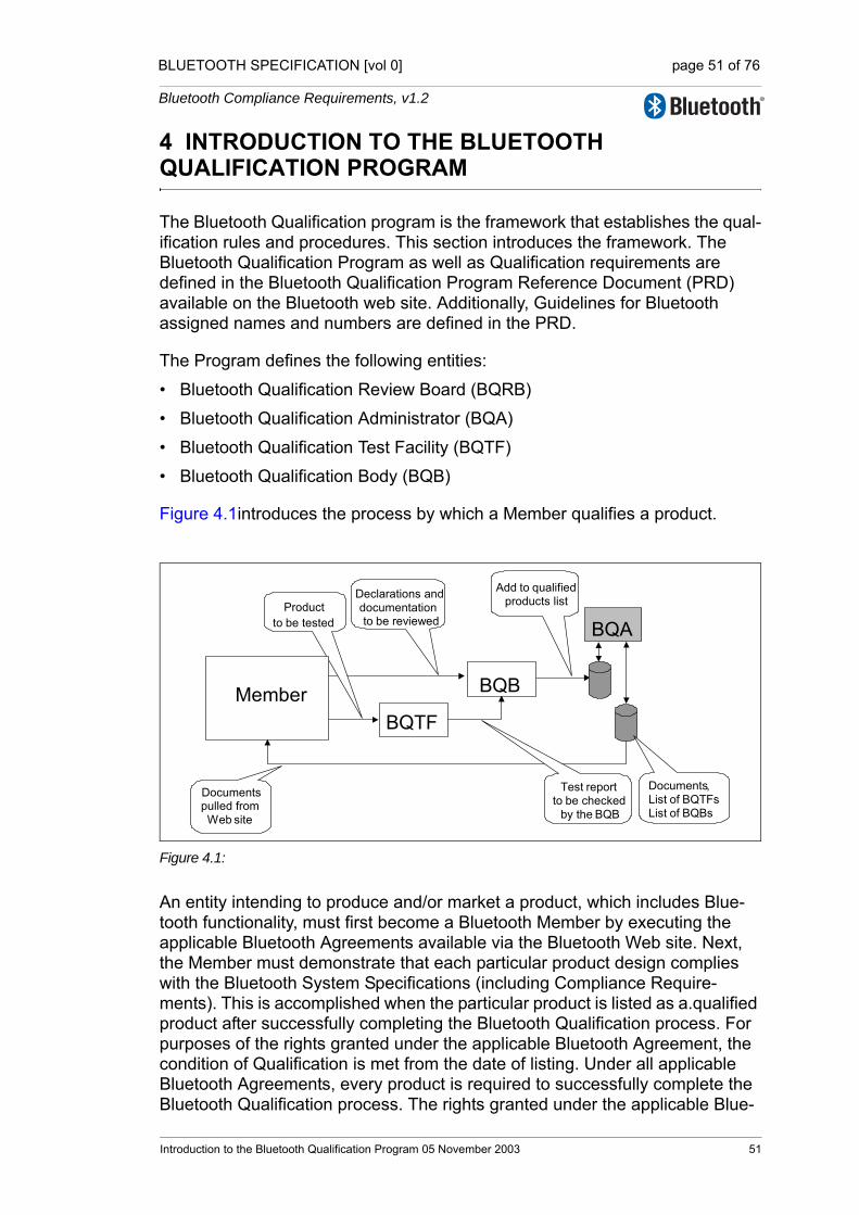
BLUETOOTH SPECIFICATION [vol 0] page 51 of 76
Bluetooth Compliance Requirements, v1.2
4 INTRODUCTION TO THE BLUETOOTH QUALIFICATION PROGRAM
The Bluetooth Qualification program is the framework that establishes the qual-ification rules and procedures. This section introduces the framework. The Bluetooth Qualification Program as well as Qualification requirements are defined in the Bluetooth Qualification Program Reference Document (PRD) available on the Bluetooth web site. Additionally, Guidelines for Bluetooth assigned names and numbers are defined in the PRD.
The Program defines the following entities:
• Bluetooth Qualification Review Board (BQRB)
• Bluetooth Qualification Administrator (BQA)
• Bluetooth Qualification Test Facility (BQTF)
• Bluetooth Qualification Body (BQB)
Figure 4.1introduces the process by which a Member qualifies a product.
Figure 4.1:
An entity intending to produce and/or market a product, which includes Blue-tooth functionality, must first become a Bluetooth Member by executing the applicable Bluetooth Agreements available via the Bluetooth Web site. Next, the Member must demonstrate that each particular product design complies with the Bluetooth System Specifications (including Compliance Require-ments). This is accomplished when the particular product is listed as a.qualified product after successfully completing the Bluetooth Qualification process. For purposes of the rights granted under the applicable Bluetooth Agreement, the condition of Qualification is met from the date of listing. Under all applicable Bluetooth Agreements, every product is required to successfully complete the Bluetooth Qualification process. The rights granted under the applicable Blue-
Add to qualified
products list
BQA
Documentspulled fromWeb site
Test report to be checked by the BQB
Declarations anddocumentationto be reviewed
BQB
BQTF
Member
Documents , List of BQTFsList of BQBs
Product to be tested
Introduction to the Bluetooth Qualification Program 05 November 2003 51
BLUETOOTH SPECIFICATION [vol 0] page 52 of 76
Bluetooth Compliance Requirements, v1.2
tooth agreements do not apply to products which have not completed the Qual-ification process.
The Member selects a BQB from the list of recognized BQBs found on the Bluetooth web site. The BQB can assist the Member throughout the entire product qualification process. The Member prepares a compliance folder and works with the BQB to develop a product test plan. If the product test plan requires testing services of a BQTF, the Member can select a BQTF that has been accredited to perform the type of testing required. All necessary docu-mentation to demonstrate compliance to the specification is provided to the BQB by the Member.
The BQB reviews the submittals and prepares a qualified product notice. In the event the BQB has a question regarding the conformance or interoperability of a product the BQB may, with the Member's permission, submit information via the BQA to the BQRB for a ruling. In the event the BQRB must be consulted, the Member will be requested to prepare a submission according to BQRB guidelines.
When all current requirements are satisfied, the BQB informs the Member that the product is ready for listing as a Bluetooth qualified product. With the con-sent of the Member, the BQB posts the product information to the official Qual-ified Product List.
A fee for product listing shall be paid by the BQB prior to product listing to finance the administration associated with the Qualification program.
Any Member can view the Bluetooth Qualified Product List. Confidential prod-uct information will not be published.
52 05 November 2003 Introduction to the Bluetooth Qualification

Master Table of Contents & Compliance Requirements
Part CAPPENDIX

BLUETOOTH SPECIFICATION [vol 0] page 54 of 76
Appendix
54 05 November 2003
BLUETOOTH SPECIFICATION [vol 0] page 55 of 76
Appendix
CONTENTS
1 Revision History.................................................................................571.1 [vol 0] Master TOC & Compliance Requirements ......................57
1.1.1 Bluetooth Compliance Requirements............................571.2 [Vol 1] Architecture & Terminology Overview .............................571.3 [Vol 2 & 3] Core System Package .............................................58
2 Contributors........................................................................................592.1 [vol 0] Master TOC & Compliance Requirements ......................59
2.1.1 Part B: Bluetooth Compliance Requirements ...............592.2 [vol 1] Architecture &Terminology Overview...............................59
2.2.1 Part A: Architectural Overview .....................................592.2.2 Part B: Acronyms & Abbreviations ................................602.2.3 Part C: Changes from Bluetooth Specification v1.1 .....60
2.3 [Vol 2] Core System Package, Controller...................................612.3.1 Part A: Radio Specification............................................612.3.2 Part B: Baseband Specification .....................................622.3.3 Part C: Link Manager Protocol ......................................652.3.4 Part D: Error Codes.......................................................662.3.5 Part E: Bluetooth Host Controller Interface Functional
Specification ..................................................................672.3.6 Part F: Message Sequence Charts ...............................682.3.7 Part G: Sample Data .....................................................692.3.8 Part H: Security Specification ........................................69
2.4 [Vol 3] Core System Package, Host ...........................................702.4.1 Part A: Logical Link Control and Adaptation Protocol
Specification ..................................................................702.4.2 Part B: Service Discovery Protocol (SDP).....................712.4.3 Part C Generic Access Profile.......................................722.4.4 Part D: Test Support ......................................................72
05 November 2003 55

BLUETOOTH SPECIFICATION [vol 0] page 56 of 76
Appendix
56 05 November 2003

BLUETOOTH SPECIFICATION [vol 0] page 57 of 76
Appendix
1 REVISION HISTORY
Public versions are marked with bold in the tables below.
Beginning with the v1.2 of the Core System Package all Bluetooth specification documents, protocols and profiles, are transferred to a new partitioning com-prising 13 volumes instead of the two (Core and Profiles) previously used.
For more detailed information about changes between version published before v1.2, please see the Appendix I “Revision History” in v1.1.
1.1 [VOL 0] MASTER TOC & COMPLIANCE REQUIREMENTS
1.1.1 Bluetooth Compliance Requirements
1.2 [VOL 1] ARCHITECTURE & TERMINOLOGY OVERVIEW
Rev Date Comments
v1.2Nov 052003
This Part was moved from the Core volume. No content changes been made to this document since v1.1
Rev Date Comments
v1.2Nov 052003
New volume with informational content. This volume will always be updated in parallel with the Core System volumes
Revision History 05 November 2003 57
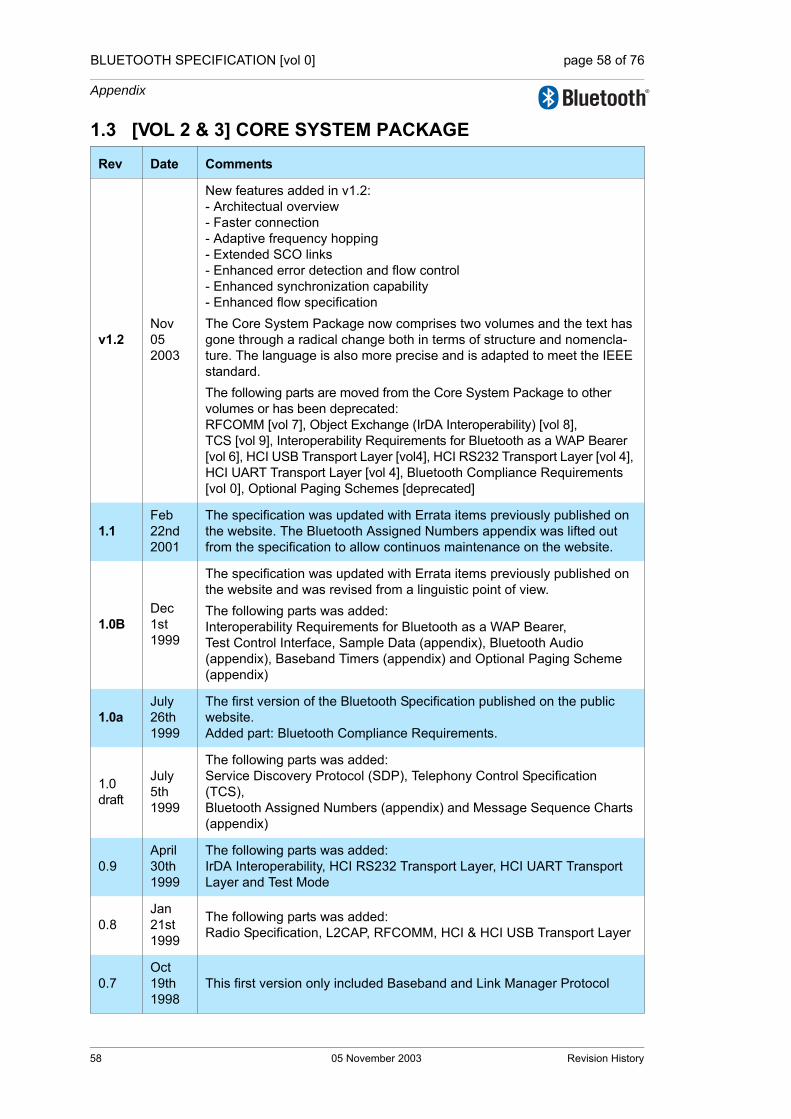
BLUETOOTH SPECIFICATION [vol 0] page 58 of 76
Appendix
1.3 [VOL 2 & 3] CORE SYSTEM PACKAGE
Rev Date Comments
v1.2Nov 052003
New features added in v1.2:- Architectual overview- Faster connection- Adaptive frequency hopping- Extended SCO links- Enhanced error detection and flow control- Enhanced synchronization capability- Enhanced flow specificationThe Core System Package now comprises two volumes and the text has gone through a radical change both in terms of structure and nomencla-ture. The language is also more precise and is adapted to meet the IEEE standard.The following parts are moved from the Core System Package to other volumes or has been deprecated:RFCOMM [vol 7], Object Exchange (IrDA Interoperability) [vol 8], TCS [vol 9], Interoperability Requirements for Bluetooth as a WAP Bearer [vol 6], HCI USB Transport Layer [vol4], HCI RS232 Transport Layer [vol 4], HCI UART Transport Layer [vol 4], Bluetooth Compliance Requirements [vol 0], Optional Paging Schemes [deprecated]
1.1Feb 22nd 2001
The specification was updated with Errata items previously published on the website. The Bluetooth Assigned Numbers appendix was lifted out from the specification to allow continuos maintenance on the website.
1.0BDec1st1999
The specification was updated with Errata items previously published on the website and was revised from a linguistic point of view.The following parts was added:Interoperability Requirements for Bluetooth as a WAP Bearer,Test Control Interface, Sample Data (appendix), Bluetooth Audio (appendix), Baseband Timers (appendix) and Optional Paging Scheme (appendix)
1.0aJuly 26th 1999
The first version of the Bluetooth Specification published on the public website.Added part: Bluetooth Compliance Requirements.
1.0 draft
July 5th 1999
The following parts was added:Service Discovery Protocol (SDP), Telephony Control Specification (TCS), Bluetooth Assigned Numbers (appendix) and Message Sequence Charts (appendix)
0.9April30th1999
The following parts was added:IrDA Interoperability, HCI RS232 Transport Layer, HCI UART Transport Layer and Test Mode
0.8Jan 21st 1999
The following parts was added:Radio Specification, L2CAP, RFCOMM, HCI & HCI USB Transport Layer
0.7Oct 19th 1998
This first version only included Baseband and Link Manager Protocol
58 05 November 2003 Revision History
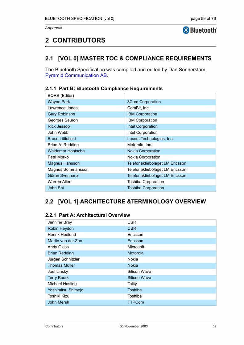
BLUETOOTH SPECIFICATION [vol 0] page 59 of 76
Appendix
2 CONTRIBUTORS
2.1 [VOL 0] MASTER TOC & COMPLIANCE REQUIREMENTS
The Bluetooth Specification was compiled and edited by Dan Sönnerstam,Pyramid Communication AB.
2.1.1 Part B: Bluetooth Compliance Requirements
2.2 [VOL 1] ARCHITECTURE &TERMINOLOGY OVERVIEW
2.2.1 Part A: Architectural Overview
BQRB (Editor)Wayne Park 3Com CorporationLawrence Jones ComBit, Inc.Gary Robinson IBM CorporationGeorges Seuron IBM CorporationRick Jessop Intel CorporationJohn Webb Intel CorporationBruce Littlefield Lucent Technologies, Inc.Brian A. Redding Motorola, Inc.Waldemar Hontscha Nokia CorporationPetri Morko Nokia CorporationMagnus Hansson Telefonaktiebolaget LM EricssonMagnus Sommansson Telefonaktiebolaget LM EricssonGöran Svennarp Telefonaktiebolaget LM EricssonWarren Allen Toshiba CorporationJohn Shi Toshiba Corporation
Jennifer Bray CSRRobin Heydon CSRHenrik Hedlund EricssonMartin van der Zee EricssonAndy Glass MicrosoftBrian Redding MotorolaJürgen Schnitzler NokiaThomas Müller NokiaJoel Linsky Silicon WaveTerry Bourk Silicon WaveMichael Hasling TalityYoshimitsu Shimojo ToshibaToshiki Kizu ToshibaJohn Mersh TTPCom
Contributors 05 November 2003 59

BLUETOOTH SPECIFICATION [vol 0] page 60 of 76
Appendix
2.2.2 Part B: Acronyms & Abbreviations
2.2.3 Part C: Changes from Bluetooth Specification v1.1
Dan Sönnerstam Pyramid Communication AB
Tom Siep Bluetooth SIG Inc.Robin Heydon CSRHenrik Hedlund EricssonRob Davies PhilipsJoel Linsky Silicon WaveJohn Mersh TTPCom
60 05 November 2003 Contributors
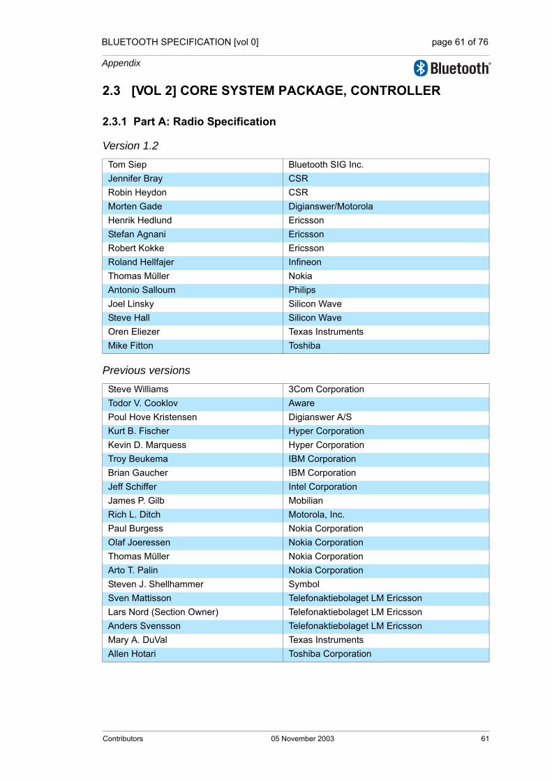
BLUETOOTH SPECIFICATION [vol 0] page 61 of 76
Appendix
2.3 [VOL 2] CORE SYSTEM PACKAGE, CONTROLLER
2.3.1 Part A: Radio Specification
Version 1.2
Previous versions
Tom Siep Bluetooth SIG Inc.Jennifer Bray CSRRobin Heydon CSRMorten Gade Digianswer/MotorolaHenrik Hedlund EricssonStefan Agnani EricssonRobert Kokke EricssonRoland Hellfajer InfineonThomas Müller NokiaAntonio Salloum PhilipsJoel Linsky Silicon WaveSteve Hall Silicon WaveOren Eliezer Texas InstrumentsMike Fitton Toshiba
Steve Williams 3Com CorporationTodor V. Cooklov AwarePoul Hove Kristensen Digianswer A/SKurt B. Fischer Hyper CorporationKevin D. Marquess Hyper CorporationTroy Beukema IBM CorporationBrian Gaucher IBM CorporationJeff Schiffer Intel CorporationJames P. Gilb MobilianRich L. Ditch Motorola, Inc.Paul Burgess Nokia CorporationOlaf Joeressen Nokia CorporationThomas Müller Nokia CorporationArto T. Palin Nokia CorporationSteven J. Shellhammer SymbolSven Mattisson Telefonaktiebolaget LM EricssonLars Nord (Section Owner) Telefonaktiebolaget LM EricssonAnders Svensson Telefonaktiebolaget LM EricssonMary A. DuVal Texas InstrumentsAllen Hotari Toshiba Corporation
Contributors 05 November 2003 61

BLUETOOTH SPECIFICATION [vol 0] page 62 of 76
Appendix
2.3.2 Part B: Baseband Specification
Version 1.2P G Madhavan AgereHongbing Gan Bandspeed, Inc. Tod Sizer Bell LabsAlexander Thoukydides CSRJennifer Bray CSRRobin Heydon CSRKim Schneider Digianswer/MotorolaKnud Dyring-Olsen Digianswer/MotorolaNiels Nielsen Digianswer/MotorolaHenrik Andersen Digianswer/Motorola Christian Gehrmann EricssonHenrik Hedlund EricssonJan Åberg EricssonMartin van der Zee EricssonRakesh Taori EricssonJaap Haartsen Ericsson Stefan Züerbes Ericsson Roland Hellfajer InfineonYC Maa Integrated Programmable Communications, Inc. HungKun Chen Integrated Programmable Communications, Inc. Steve McGowan IntelAdrian Stephens Mobilian Corporation Jim Lansford Mobilian Corporation Eric Meihofer Motorola Arto Palin NokiaCarmen Kuhl NokiaHannu Laine NokiaJürgen Schnitzler NokiaPäivi Ruuska NokiaThomas Müller NokiaAntonio Salloum PhilipsHarmke de Groot PhilipsMarianne van de Casteelee PhilipsRob Davies PhilipsRoland Matthijssen PhilipsJoel Linsky (section owner) Silicon WaveTerry Bourk Silicon WaveGary Schneider Symbol Technologies, Inc. Stephen J. Shellhammer Symbol Technologies, Inc. Michael Hasling TalityAmihai Kidron Texas InstrumentsDan Michael Texas Instruments
62 05 November 2003 Contributors
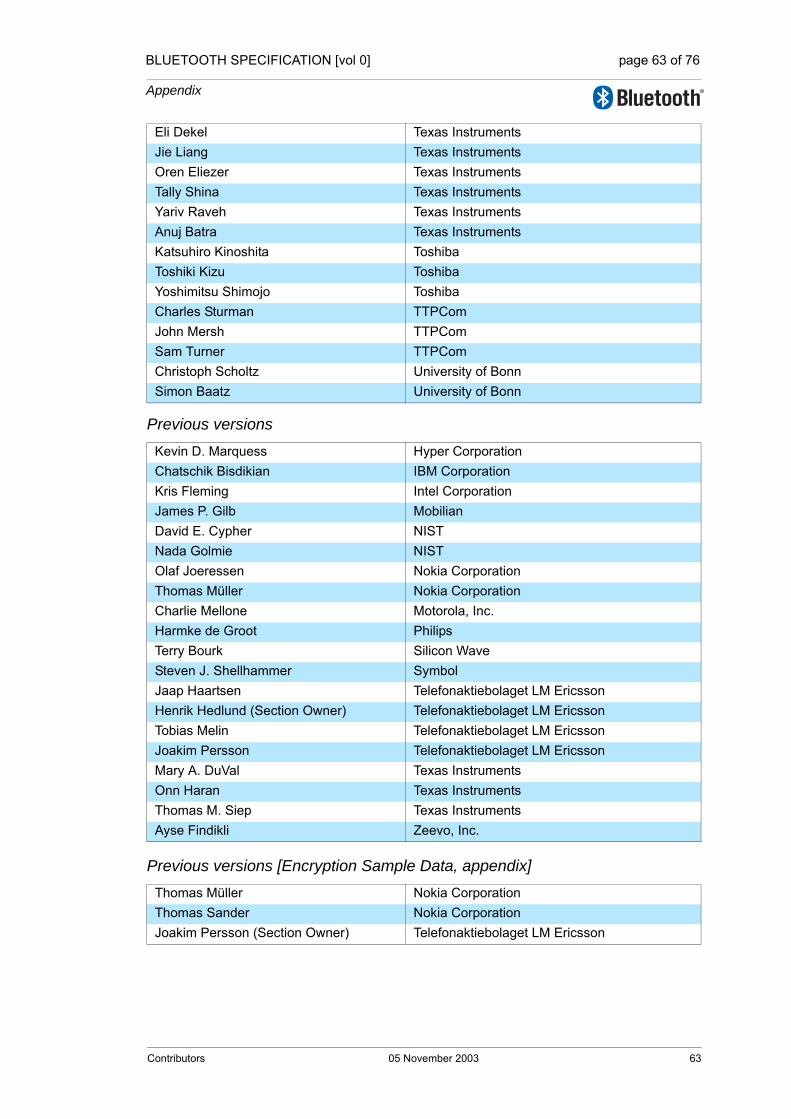
BLUETOOTH SPECIFICATION [vol 0] page 63 of 76
Appendix
Previous versions
Previous versions [Encryption Sample Data, appendix]
Eli Dekel Texas InstrumentsJie Liang Texas InstrumentsOren Eliezer Texas InstrumentsTally Shina Texas InstrumentsYariv Raveh Texas InstrumentsAnuj Batra Texas Instruments Katsuhiro Kinoshita ToshibaToshiki Kizu ToshibaYoshimitsu Shimojo ToshibaCharles Sturman TTPComJohn Mersh TTPComSam Turner TTPComChristoph Scholtz University of BonnSimon Baatz University of Bonn
Kevin D. Marquess Hyper CorporationChatschik Bisdikian IBM CorporationKris Fleming Intel CorporationJames P. Gilb MobilianDavid E. Cypher NISTNada Golmie NISTOlaf Joeressen Nokia CorporationThomas Müller Nokia CorporationCharlie Mellone Motorola, Inc.Harmke de Groot PhilipsTerry Bourk Silicon WaveSteven J. Shellhammer SymbolJaap Haartsen Telefonaktiebolaget LM EricssonHenrik Hedlund (Section Owner) Telefonaktiebolaget LM EricssonTobias Melin Telefonaktiebolaget LM EricssonJoakim Persson Telefonaktiebolaget LM EricssonMary A. DuVal Texas InstrumentsOnn Haran Texas InstrumentsThomas M. Siep Texas InstrumentsAyse Findikli Zeevo, Inc.
Thomas Müller Nokia CorporationThomas Sander Nokia CorporationJoakim Persson (Section Owner) Telefonaktiebolaget LM Ericsson
Contributors 05 November 2003 63

BLUETOOTH SPECIFICATION [vol 0] page 64 of 76
Appendix
Previous versions [Bluetooth Audio, appendix]
Previous versions [Baseband Timers, appendix]
Magnus Hansson Telefonaktiebolaget LM EricssonFisseha Mekuria Telefonaktiebolaget LM EricssonMats Omrin Telefonaktiebolaget LM EricssonJoakim Persson (Section Owner) Telefonaktiebolaget LM Ericsson
David E. Cyper NISTJaap Haartsen (Section Owner) Telefonaktiebolaget LM EricssonJoakim Persson Telefonaktiebolaget LM EricssonAyse Findikli Zeevo, Inc.
64 05 November 2003 Contributors
BLUETOOTH SPECIFICATION [vol 0] page 65 of 76
Appendix
2.3.3 Part C: Link Manager Protocol
Version 1.2Jennifer Bray CSRRobin Heydon CSRSimon Morris CSRAlexander Thoukydides CSR Kim Schneider Digianswer/MotorolaKnud Dyring-Olsen Digianswer/MotorolaHenrik Andersen Digianswer/Motorola Jan Åberg EricssonMartin van der Zee EricssonRoland Hellfajer InfineonYC Maa Integrated Programmable Communications, Inc.Steve McGowan IntelTod Sizer Lucent Technologies Adrian Stephens Mobilian Jürgen Schnitzler NokiaThomas Müller NokiaCarmen Kuhl NokiaArto Palin NokiaThomas Müller NokiaRoland Matthijssen PhilipsRob Davies PhilipsHarmke de Groot PhilipsAntonio Salloum PhilipsJoel Linsky Silicon WaveTerry Bourk Silicon WaveYariv Raveh Texas InstrumentsTally Shina Texas InstrumentsAmihai Kidron Texas InstrumentsYoshimitsu Shimojo ToshibaToshiki Kizu ToshibaJohn Mersh (section owner) TTPComSam Turner TTPCom
Contributors 05 November 2003 65
BLUETOOTH SPECIFICATION [vol 0] page 66 of 76
Appendix
Previous versions
2.3.4 Part D: Error Codes
Version 1.2
This part was earlier included in the LMP and HCI functional Specifications.
Kim Schneider Digianswer A/S Toru Aihara IBM CorporationChatschik Bisdikian IBM CorporationKris Fleming Intel CorporationDavid E. Cypher NISTThomas Busse Nokia CorporationJulien Corthial Nokia CorporationOlaf Joeressen Nokia CorporationThomas Müller Nokia CorporationDong Nguyen Nokia CorporationHarmke de Groot PhilipsTerry Bourk Silicon WaveJohannes Elg Telefonaktiebolaget LM EricssonJaap Haartsen Telefonaktiebolaget LM EricssonTobias Melin (Section Owner) Telefonaktiebolaget LM EricssonMary A. DuVal Texas InstrumentsOnn Haran Texas InstrumentsJohn Mersh TTPCom
Robin Heydon (section owner) CSRRoland Hellfajer InfineonJoel Linsky Silicon WaveJohn Mersh TTPCom
66 05 November 2003 Contributors

BLUETOOTH SPECIFICATION [vol 0] page 67 of 76
Appendix
2.3.5 Part E: Bluetooth Host Controller Interface Functional SpecificationVersion 1.2
Previous versions
Robin Heydon (section owner CSRJennifer Bray CSRAlexander Thoukydides CSRKnud Dyring-Olsen Digianswer/MotorolaHenrik Andersen Digianswer/Motorola Jan Åberg EricssonMartin van der Zee EricssonDon Liechty Extended Systems Kevin Marquess Hyper Corp Roland Hellfajer InfineonYC Maa Integrated Programmable Communications, Inc. Steve McGowan IntelTod Sizer Lucent Technologies Tsuyoshi Okada Matsushita Electric Industrial Co. Ltd Andy Glass MicrosoftAdrian Stephens Mobilian Len Ott MotorolaJürgen Schnitzler NokiaThomas Müller NokiaRene Tischer Nokia Rob Davies PhilipsAntonio Salloum PhilipsJoel Linsky Silicon WaveTerry Bourk Silicon WaveLen Ott Socket CommunicationsRandy Erman Taiyo Yuden Yoshimitsu Shimojo ToshibaToshiki Kizu ToshibaKatsuhiro Kinoshita ToshibaSam Turner TTPComJohn Mersh TTPCom
Todor Cooklev 3Com CorporationToru Aihara IBM CorporationChatschik Bisdikian IBM CorporationNathan Lee IBM CorporationAkihiko Mizutani IBM CorporationLes Cline Intel CorporationBailey Cross Intel CorporationKris Fleming Intel CorporationRobert Hunter Intel CorporationJon Inouye Intel Corporation
Contributors 05 November 2003 67

BLUETOOTH SPECIFICATION [vol 0] page 68 of 76
Appendix
2.3.6 Part F: Message Sequence ChartsVersion 1.2
Previous versions
Srikanth Kambhatla Intel CorporationSteve Lo Intel CorporationVijay Suthar Intel CorporationBruce P. Kraemer IntersilGreg Muchnik Motorola, Inc.David E. Cypher NISTThomas Busse Nokia CorporationJulien Courthial Nokia CorporationThomas Müller Nokia CorporationDong Nguyen Nokia CorporationJürgen Schnitzler Nokia CorporationFujio Watanabe Nokia CorporationChristian Zechlin Nokia CorporationJohannes Elg Telefonaktiebolaget LM EricssonChristian Johansson (Section Owner) Telefonaktiebolaget LM EricssonPatrik Lundin Telefonaktiebolaget LM EricssonTobias Melin Telefonaktiebolaget LM EricssonMary A. DuVal Texas InstrumentsThomas M. Siep Texas InstrumentsMasahiro Tada Toshiba CorporationJohn Mersh TTPCom
Tom Siep Bluetooth SIG Inc.Robin Heydon (section owner) CSRSimon Morris CSR. Jan Åberg EricssonChristian Gehrmann EricssonJoel Linsky Silicon WaveJohn Mersh TTPCom
Todor Cooklev 3Com CorporationToru Aihara IBM CorporationChatschik Bisdikian IBM CorporationNathan Lee IBM CorporationKris Fleming Intel Corporation.Greg Muchnik Motorola, Inc.David E. Cypher NISTThomas Busse Nokia CorporationDong Nguyen (Section Owner) Nokia CorporationFujio Watanabe Nokia CorporationChristian Johansson Telefonaktiebolaget LM EricssonTobias Melin Telefonaktiebolaget LM EricssonMary A. DuVal Texas Instruments
68 05 November 2003 Contributors

BLUETOOTH SPECIFICATION [vol 0] page 69 of 76
Appendix
2.3.7 Part G: Sample Data
Version 1.2
Previous versions
2.3.8 Part H: Security Specification
Please see Part B (Section 2.3.2 on page 62). The Security specification was until recently a part of the Baseband specification.
Joel Linsky Silicon Wave
Thomas Müller Nokia CorporationThomas Sander Nokia CorporationJoakim Persson (Section Owner) Telefonaktiebolaget LM Ericsson
Contributors 05 November 2003 69

BLUETOOTH SPECIFICATION [vol 0] page 70 of 76
Appendix
2.4 [VOL 3] CORE SYSTEM PACKAGE, HOST
2.4.1 Part A: Logical Link Control and Adaptation Protocol Specification
Version 1.2
Previous versions
Tom Siep Bluetooth SIG Inc.Carsten Andersen (section owner CSRJennifer Bray CSRJan Åberg EricssonMartin van der Zee EricssonSam Ravnborg EricssonStefan Agnani EricssonSteve McGowan IntelJoby Lafky MicrosoftDoron Holan MicrosoftAndy Glass MicrosoftBrian Redding MotorolaJürgen Schnitzler NokiaThomas Müller NokiaRob Davies PhilipsTerry Bourk Silicon WaveMichael Hasling Tality
Jon Burgess 3Com CorporationPaul Moran 3Com CorporationDoug Kogan Extended SystemsKevin D. Marquess Hyper CorporationToru Aihara IBM CorporationChatschik Bisdikian IBM CorporationKris Fleming Intel CorporationUma Gadamsetty Intel CorporationRobert Hunter Intel CorporationJon Inouye Intel CorporationSteve C. Lo Intel CorporationChunrong Zhu Intel CorporationSergey Solyanik Microsoft CorporationDavid E. Cypher NISTNada Golmie NISTThomas Busse Nokia CorporationRauno Makinen Nokia CorporationThomas Müller Nokia CorporationPetri Nykänen Nokia CorporationPeter Ollikainen Nokia CorporationPetri O. Nurminen Nokia Corporation
70 05 November 2003 Contributors

BLUETOOTH SPECIFICATION [vol 0] page 71 of 76
Appendix
2.4.2 Part B: Service Discovery Protocol (SDP)
Version 1.2
Previous versions
Johannes Elg Telefonaktiebolaget LM EricssonJaap Haartsen Telefonaktiebolaget LM EricssonElco Nijboer Telefonaktiebolaget LM EricssonIngemar Nilsson Telefonaktiebolaget LM EricssonStefan Runesson Telefonaktiebolaget LM EricssonGerrit Slot Telefonaktiebolaget LM EricssonJohan Sörensen Telefonaktiebolaget LM EricssonGoran Svennarp Telefonaktiebolaget LM EricssonMary A. DuVal Texas InstrumentsThomas M. Siep Texas InstrumentsKinoshita Katsuhiro Toshiba Corporation
Ned Plasson 3Com CorporationJohn Avery ConvergenceJason Kronz ConvergenceChatschik Bisdikian IBM CorporationParviz Kermani IBM CorporationBrent Miller IBM CorporationDick Osterman IBM CorporationBob Pascoe IBM CorporationJon Inouye Intel CorporationSrikanth Kambhatla Intel CorporationJay Eaglstun Motorola, Inc.Dale Farnsworth (Section Owner) Motorola, Inc.Jean-Michel Rosso Motorola, Inc.Jan Grönholm Nokia Corporation Kati Rantala Nokia CorporationThomas Müller Nokia CorporationJohannes Elg Telefonaktiebolaget LM EricssonKazuaki Iwamura Toshiba Corporation
Contributors 05 November 2003 71
BLUETOOTH SPECIFICATION [vol 0] page 72 of 76
Appendix
2.4.3 Part C Generic Access Profile
Version 1.2
Previous versions
2.4.4 Part D: Test Support
Version 1.2
Previous versions [Test Mode]
Jennifer Bray CSRAlexander Thoukydides CSRChristian Gehrmann EricssonHenrik Hedlund EricssonJan Åberg EricssonStefan Agnani EricssonThomas Müller NokiaJoel Linsky Silicon WaveTerry Bourk Silicon WaveKatsuhiro Kinoshita Toshiba
Ken Morley 3Com CorporationChatschik Bisdikian IBM CorporationJon Inouye Intel CorporationBrian Redding Motorola, Inc.David E. Cypher NISTStephane Bouet Nokia CorporationThomas Müller Nokia CorporationMartin Roter Nokia CorporationJohannes Elg Telefonaktiebolaget LM EricssonPatric Lind (Section Owner) Telefonaktiebolaget LM EricssonErik Slotboom Telefonaktiebolaget LM EricssonJohan Sörensen Telefonaktiebolaget LM Ericsson
Emilio Mira Escartis CetecomRobin Heydon CSRJennifer Bray CSRStefan Agnani (section owner) EricssonTerry Bourk Silicon WaveJoel Linsky Silicon WaveMichael Hasling Tality
Jeffrey Schiffer Intel CorporationDavid E. Cypher NISTDaniel Bencak Nokia CorporationArno Kefenbaum Nokia CorporationThomas Müller (Section Owner) Nokia Corporation
72 05 November 2003 Contributors

BLUETOOTH SPECIFICATION [vol 0] page 73 of 76
Appendix
Previous versions [Test Control Interface]
Roland Schmale Nokia CorporationFujio Watanabe Nokia CorporationStefan Agnani Telefonaktiebolaget LM EricssonMårten Mattsson Telefonaktiebolaget LM EricssonTobias Melin Telefonaktiebolaget LM EricssonLars Nord Telefonaktiebolaget LM EricssonFredrik Töörn Telefonaktiebolaget LM EricssonJohn Mersh TTPComAyse Findikli Zeevo, Inc.
Mike Feldman Motorola, Inc.Thomas Müller Nokia CorporationStefan Agnani (Section Owner) Telefonaktiebolaget LM EricssonMårten Mattsson Telefonaktiebolaget LM EricssonDan Sönnerstam Telefonaktiebolaget LM Ericsson
Contributors 05 November 2003 73

BLUETOOTH SPECIFICATION [vol 0] page 74 of 76
Appendix
74 05 November 2003 Contributors


76
Specificationof the Bluetooth System
Wireless connections made easy
Architecture &TerminologyOverviewVersion 1.2 05 November 2003
Specification Volume 1

BLUETOOTH SPECIFICATION Version 1.2 [vol 1] page 2 of 82
Revision History
The Revision History is shown in the “Appendix” on page 53[vol. 0].
Contributors
The persons who contributed to this specification are listed in the , “Appendix” on page 53[vol. 0].
Web Site
This specification can also be found on the official Bluetooth website: http://www.bluetooth.com
Disclaimer and Copyright Notice
The copyright in these specifications is owned by the Promoter Members of Bluetooth SIG, Inc. (“Bluetooth SIG”). Use of these specifications and any related intellectual property (collectively, the “Specification”), is governed by the Promoters Membership Agreement among the Promoter Members and Blue-tooth SIG (the “Promoters Agreement”), certain membership agreements between Bluetooth SIG and its Adopter and Associate Members (the “Member-ship Agreements”) and the Bluetooth Specification Early Adopters Agreements (“1.2 Early Adopters Agreements”) among Early Adopter members of the unin-corporated Bluetooth special interest group and the Promoter Members (the “Early Adopters Agreement”). Certain rights and obligations of the Promoter Members under the Early Adopters Agreements have been assigned to Blue-tooth SIG by the Promoter Members.
Use of the Specification by anyone who is not a member of Bluetooth SIG or a party to an Early Adopters Agreement (each such person or party, a “Mem-ber”), is prohibited. The legal rights and obligations of each Member are gov-erned by their applicable Membership Agreement, Early Adopters Agreement or Promoters Agreement. No license, express or implied, by estoppel or other-wise, to any intellectual property rights are granted herein.
Any use of the Specification not in compliance with the terms of the applicable Membership Agreement, Early Adopters Agreement or Promoters Agreement is prohibited and any such prohibited use may result in termination of the appli-cable Membership Agreement or Early Adopters Agreement and other liability permitted by the applicable agreement or by applicable law to Bluetooth SIG or any of its members for patent, copyright and/or trademark infringement.
2 05 November 2003

BLUETOOTH SPECIFICATION Version 1.2 [vol 1] page 3 of 82
THE SPECIFICATION IS PROVIDED “AS IS” WITH NO WARRANTIES WHATSOEVER, INCLUDING ANY WARRANTY OF MERCHANTABILITY, NONINFRINGEMENT, FITNESS FOR ANY PARTICULAR PURPOSE, SATIS-FACTORY QUALITY, OR REASONABLE SKILL OR CARE, OR ANY WAR-RANTY ARISING OUT OF ANY COURSE OF DEALING, USAGE, TRADE PRACTICE, PROPOSAL, SPECIFICATION OR SAMPLE.
Each Member hereby acknowledges that products equipped with the Blue-tooth® technology (“Bluetooth® Products”) may be subject to various regula-tory controls under the laws and regulations of various governments worldwide. Such laws and regulatory controls may govern, among other things, the combi-nation, operation, use, implementation and distribution of Bluetooth® Prod-ucts. Examples of such laws and regulatory controls include, but are not limited to, airline regulatory controls, telecommunications regulations, technology transfer controls and health and safety regulations. Each Member is solely responsible for the compliance by their Bluetooth® Products with any such laws and regulations and for obtaining any and all required authorizations, per-mits, or licenses for their Bluetooth® Products related to such regulations within the applicable jurisdictions. Each Member acknowledges that nothing in the Specification provides any information or assistance in connection with securing such compliance, authorizations or licenses. NOTHING IN THE SPECIFICATION CREATES ANY WARRANTIES, EITHER EXPRESS OR IMPLIED, REGARDING SUCH LAWS OR REGULATIONS.
ALL LIABILITY, INCLUDING LIABILITY FOR INFRINGEMENT OF ANY INTELLECTUAL PROPERTY RIGHTS OR FOR NONCOMPLIANCE WITH LAWS, RELATING TO USE OF THE SPECIFICATION IS EXPRESSLY DIS-CLAIMED. BY USE OF THE SPECIFICATION, EACH MEMBER EXPRESSLY WAIVES ANY CLAIM AGAINST BLUETOOTH SIG AND ITS PROMOTER MEMBERS RELATED TO USE OF THE SPECIFICATION.
Bluetooth SIG reserves the right to adopt any changes or alterations to the Specification as it deems necessary or appropriate and to adopt a process for adding new Bluetooth® profiles after the release of the Specification.
Copyright © 1999, 2000, 2001, 2002, 2003
Agere Systems, Inc.,Ericsson Technology Licensing, AB,IBM Corporation,Intel Corporation,Microsoft Corporation,Motorola, Inc.,Nokia Corporation,Toshiba Corporation
*Third-party brands and names are the property of their respective owners.
05 November 2003 3

BLUETOOTH SPECIFICATION Version 1.2 [vol 1] page 4 of 82
4 05 November 2003

BLUETOOTH SPECIFICATION Version 1.2 [vol 1] page 5 of 82
TABLE OF CONTENTS
Part AARCHITECTURE
Contents ........................................................................................................111 General Description ...........................................................................13
1.1 Overview of Operation ...............................................................131.2 Nomenclature.............................................................................15
2 Core System Architecture .................................................................192.1 Core Architectural Blocks...........................................................22
2.1.1 Channel manager..........................................................222.1.2 L2CAP resource manager.............................................222.1.3 Device manager ............................................................232.1.4 Link manager.................................................................232.1.5 Baseband resource manager ........................................232.1.6 Link controller ................................................................242.1.7 RF..................................................................................24
3 Data Transport Architecture..............................................................253.1 Core Traffic Bearers...................................................................26
3.1.1 Framed data traffic ........................................................273.1.2 Unframed data traffic .....................................................283.1.3 Reliability of traffic bearers ............................................28
3.2 Transport Architecture Entities...................................................303.2.1 Bluetooth generic packet structure................................30
3.3 Physical Channels......................................................................323.3.1 Basic piconet channel ...................................................33
3.3.1.1 Overview.........................................................333.3.1.2 Characteristics ................................................333.3.1.3 Topology .........................................................343.3.1.4 Supported layers.............................................34
3.3.2 Adapted piconet channel...............................................343.3.2.1 Overview.........................................................34
3.3.3 Inquiry scan channel .....................................................353.3.3.1 Overview.........................................................353.3.3.2 Characteristics ................................................353.3.3.3 Topology .........................................................363.3.3.4 Supported layers.............................................36
05 November 2003 5

BLUETOOTH SPECIFICATION Version 1.2 [vol 1] page 6 of 82
3.3.4 Page scan channel .......................................................363.3.4.1 Overview.........................................................363.3.4.2 Characteristics................................................363.3.4.3 Topology .........................................................373.3.4.4 Supported layers ............................................37
3.4 Physical Links ............................................................................373.4.1 Links supported by the basic and adapted piconet physi-
cal channel383.4.1.1 Active physical link .........................................383.4.1.2 Parked physical link........................................38
3.4.2 Links supported by the scanning physical channels .....393.5 Logical Links and Logical Transports.........................................39
3.5.1 Casting..........................................................................413.5.2 Scheduling and acknowledgement scheme..................413.5.3 Class of data .................................................................423.5.4 Asynchronous connection-oriented (ACL) ....................423.5.5 Synchronous connection-oriented (SCO) .....................433.5.6 Extended synchronous connection-oriented (eSCO)....443.5.7 Active slave broadcast (ASB)........................................443.5.8 Parked slave broadcast (PSB) ......................................453.5.9 Logical links ..................................................................463.5.10 ACL Control Logical Link (ACL-C) ................................473.5.11 User Asynchronous/Isochronous Logical Link (ACL-U) 473.5.12 User Synchronous/Extended Synchronous Logical Links
(SCO-S/eSCO-S)473.6 L2CAP Channels .......................................................................48
4 Communication Topology.................................................................494.1 Piconet Topology .......................................................................494.2 Operational Procedures and Modes ..........................................51
4.2.1 Inquiry (Discovering) Procedure....................................514.2.2 Paging (Connecting) Procedure....................................524.2.3 Connected mode...........................................................524.2.4 Hold mode.....................................................................534.2.5 Sniff mode .....................................................................534.2.6 Parked state ..................................................................544.2.7 Role switch procedure...................................................54
6 05 November 2003

BLUETOOTH SPECIFICATION Version 1.2 [vol 1] page 7 of 82
Part BACRONYMS & ABBREVIATIONS
1 List of Acronyms and Abbreviations................................................572 Abbreviations of the Specification Names ......................................65
Part CCHANGES FROM BLUETOOTH SPECIFICATION V 1.1
Contents ........................................................................................................691 New Features......................................................................................712 Changes in Wording ..........................................................................73
2.1 IEEE Language Update .............................................................732.1.1 Shall ..............................................................................742.1.2 Must...............................................................................742.1.3 Will.................................................................................742.1.4 Should ...........................................................................742.1.5 May................................................................................752.1.6 Can................................................................................75
2.2 Nomenclature Changes .............................................................75
3 Structure Changes .............................................................................774 Deprecated Specifications ................................................................79
4.1 Deprecated Features .................................................................794.2 Deprecated Profiles....................................................................79
05 November 2003 7

BLUETOOTH SPECIFICATION Version 1.2 [vol 1] page 8 of 82
8 05 November 2003

Architecture & Terminology Overview
1.2
Part A
Architecture

BLUETOOTH SPECIFICATION Version 1.2 [vol 1] page 10 of 82
Architecture
10 05 November 2003

BLUETOOTH SPECIFICATION Version 1.2 [vol 1] page 11 of 82
Architecture
CONTENTS
1 General Description ...........................................................................131.1 Overview of Operation ...............................................................131.2 Nomenclature.............................................................................15
2 Core System Architecture .................................................................192.1 Core Architectural Blocks...........................................................22
2.1.1 Channel manager..........................................................222.1.2 L2CAP resource manager.............................................222.1.3 Device manager ............................................................232.1.4 Link manager.................................................................232.1.5 Baseband resource manager ........................................232.1.6 Link controller ................................................................242.1.7 RF..................................................................................24
3 Data Transport Architecture..............................................................253.1 Core Traffic Bearers...................................................................26
3.1.1 Framed data traffic ........................................................273.1.2 Unframed data traffic .....................................................283.1.3 Reliability of traffic bearers ............................................28
3.2 Transport Architecture Entities...................................................303.2.1 Bluetooth generic packet structure................................30
3.3 Physical Channels......................................................................323.3.1 Basic piconet channel ...................................................33
3.3.1.1 Overview.........................................................333.3.1.2 Characteristics ................................................333.3.1.3 Topology .........................................................343.3.1.4 Supported layers.............................................34
3.3.2 Adapted piconet channel...............................................343.3.2.1 Overview.........................................................34
3.3.3 Inquiry scan channel .....................................................353.3.3.1 Overview.........................................................353.3.3.2 Characteristics ................................................353.3.3.3 Topology .........................................................363.3.3.4 Supported layers.............................................36
3.3.4 Page scan channel........................................................363.3.4.1 Overview.........................................................363.3.4.2 Characteristics ................................................363.3.4.3 Topology .........................................................373.3.4.4 Supported layers.............................................37
05 November 2003 11

BLUETOOTH SPECIFICATION Version 1.2 [vol 1] page 12 of 82
Architecture
3.4 Physical Links ............................................................................373.4.1 Links supported by the basic and adapted piconet physi-
cal channel ....................................................................383.4.1.1 Active physical link .........................................383.4.1.2 Parked physical link........................................38
3.4.2 Links supported by the scanning physical channels .....393.5 Logical Links and Logical Transports.........................................39
3.5.1 Casting..........................................................................413.5.2 Scheduling and acknowledgement scheme..................413.5.3 Class of data .................................................................423.5.4 Asynchronous connection-oriented (ACL) ....................423.5.5 Synchronous connection-oriented (SCO) .....................433.5.6 Extended synchronous connection-oriented (eSCO)....443.5.7 Active slave broadcast (ASB)........................................443.5.8 Parked slave broadcast (PSB) ......................................453.5.9 Logical links ..................................................................463.5.10 ACL Control Logical Link (ACL-C) ................................473.5.11 User Asynchronous/Isochronous Logical Link (ACL-U) 473.5.12 User Synchronous/Extended Synchronous Logical Links
(SCO-S/eSCO-S) ..........................................................473.6 L2CAP Channels .......................................................................48
4 Communication Topology.................................................................494.1 Piconet Topology .......................................................................494.2 Operational Procedures and Modes ..........................................51
4.2.1 Inquiry (Discovering) Procedure....................................514.2.2 Paging (Connecting) Procedure....................................524.2.3 Connected mode...........................................................524.2.4 Hold mode.....................................................................534.2.5 Sniff mode .....................................................................534.2.6 Parked state ..................................................................544.2.7 Role switch procedure...................................................54
12 05 November 2003
BLUETOOTH SPECIFICATION Version 1.2 [vol 1] page 13 of 82
Architecture
1 GENERAL DESCRIPTION
Bluetooth wireless technology is a short-range communications system intended to replace the cable(s) connecting portable and/or fixed electronic devices. Key features are robustness, low power, and low cost. Many features of the core specification are optional, allowing product differentiation.
The Bluetooth core system consists of an RF transceiver, baseband, and pro-tocol stack. The system offers services that enable the connection of devices and the exchange of a variety of classes of data between these devices.
This chapter of the specification provides an overview of the Bluetooth system architecture, communication topologies and data transport features. The text in this chapter of the specification should be treated as informational and used as a background and for context-setting.
1.1 OVERVIEW OF OPERATION
The Bluetooth RF (physical layer) operates in the unlicensed ISM band at 2.4 GHz. The system employs a frequency hop transceiver to combat interference and fading and provides many FHSS carriers. RF operation uses a shaped, binary FM modulation to minimize transceiver complexity. The symbol rate is 1 Megasymbol per second (Ms/s) supporting the bit rate of 1 Megabit per second (Mb/s).
During typical operation a physical radio channel is shared by a group of devices that are synchronized to a common clock and frequency hopping pat-tern. One device provides the synchronization reference and is known as the master. All other devices are known as slaves. A group of devices synchro-nized in this fashion form a piconet. This is the fundamental form of communi-cation in the Bluetooth wireless technology.
Devices in a piconet use a specific frequency hopping pattern, which is algo-rithmically determined by certain fields in the Bluetooth address and clock of the master. The basic hopping pattern is a pseudo-random ordering of the 79 frequencies in the ISM band. The hopping pattern may be adapted to exclude a portion of the frequencies that are used by interferring devices. The adaptive hopping technique improves Bluetooth co-existence with static (non-hopping) ISM systems when these are co-located.
The physical channel is sub-divided into time units known as slots. Data is transmitted between Bluetooth devices in packets, that are positioned in these slots. When circumstances permit, a number of consecutive slots may be allo-cated to a single packet. Frequency hopping takes place between the transmis-sion or reception of packets. Bluetooth technology provides the effect of full duplex transmission through the use of a Time-Division Duplex (TDD) scheme.
General Description 05 November 2003 13
BLUETOOTH SPECIFICATION Version 1.2 [vol 1] page 14 of 82
Architecture
Above the physical channel there is a layering of links and channels and asso-ciated control protocols. The hierarchy of channels and links from the physical channel upwards is physical channel, physical link, logical transport, logical link and L2CAP channel. These are discussed in more detail in Section 3.3 on page 32 - Section 3.6 on page 48 but are introduced here to aid the under-standing of the remainder of this section.
Within a physical channel, a physical link is formed between any two devices that transmit packets in either direction between them. In a piconet physical channel there are restrictions on which devices may form a physical link. There is a physical link between each slave and the master. Physical links are not formed directly between the slaves in a piconet.
The physical link is used as a transport for one or more logical links that sup-port unicast synchronous, asynchronous and isochronous traffic, and broad-cast traffic. Traffic on logical links is multiplexed onto the physical link by occupying slots assigned by a scheduling function in the resource manager.
A control protocol for the baseband and physical layers is carried over logical links in addition to user data. This is the link manager protocol (LMP). Devices that are active in a piconet have a default asynchronous connection-oriented logical transport that is used to transport the LMP protocol signalling. For his-torical reasons this is known as the ACL logical transport. The default ACL log-ical transport is the one that is created whenever a device joins a piconet. Additional logical transports may be created to transport synchronous data streams when this is required.
The Link Manager function uses LMP to control the operation of devices in the piconet and provide services to manage the lower architectural layers (radio layer and baseband layer). The LMP protocol is only carried on the default ACL logical transport and the default broadcast logical transport.
Above the baseband layer the L2CAP layer provides a channel-based abstrac-tion to applications and services. It carries out segmentation and reassembly of application data and multiplexing and de-multiplexing of multiple channels over a shared logical link. L2CAP has a protocol control channel that is carried over the default ACL logical transport. Application data submitted to the L2CAP pro-tocol may be carried on any logical link that supports the L2CAP protocol.
14 05 November 2003 General Description
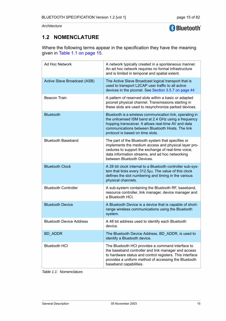
BLUETOOTH SPECIFICATION Version 1.2 [vol 1] page 15 of 82
Architecture
1.2 NOMENCLATURE
Where the following terms appear in the specification they have the meaning given in Table 1.1 on page 15.
Ad Hoc Network A network typically created in a spontaneous manner. An ad hoc network requires no formal infrastructure and is limited in temporal and spatial extent.
Active Slave Broadcast (ASB) The Active Slave Broadcast logical transport that is used to transport L2CAP user traffic to all active devices in the piconet. See Section 3.5.7 on page 44
Beacon Train A pattern of reserved slots within a basic or adapted piconet physical channel. Transmissions starting in these slots are used to resynchronize parked devices.
Bluetooth Bluetooth is a wireless communication link, operating in the unlicensed ISM band at 2.4 GHz using a frequency hopping transceiver. It allows real-time AV and data communications between Bluetooth Hosts. The link protocol is based on time slots.
Bluetooth Baseband The part of the Bluetooth system that specifies or implements the medium access and physical layer pro-cedures to support the exchange of real-time voice, data information streams, and ad hoc networking between Bluetooth Devices.
Bluetooth Clock A 28 bit clock internal to a Bluetooth controller sub-sys-tem that ticks every 312.5µs. The value of this clock defines the slot numbering and timing in the various physical channels.
Bluetooth Controller A sub-system containing the Bluetooth RF, baseband, resource controller, link manager, device manager and a Bluetooth HCI.
Bluetooth Device A Bluetooth Device is a device that is capable of short-range wireless communications using the Bluetooth system.
Bluetooth Device Address A 48 bit address used to identify each Bluetooth device.
BD_ADDR The Bluetooth Device Address, BD_ADDR, is used to identify a Bluetooth device.
Bluetooth HCI The Bluetooth HCI provides a command interface to the baseband controller and link manager and access to hardware status and control registers. This interface provides a uniform method of accessing the Bluetooth baseband capabilities.
Table 1.1: Nomenclature.
General Description 05 November 2003 15

BLUETOOTH SPECIFICATION Version 1.2 [vol 1] page 16 of 82
Architecture
Bluetooth Host A Bluetooth Host is a computing device, peripheral, cel-lular telephone, access point to PSTN network or LAN, etc. A Bluetooth Host attached to a Bluetooth Controller may communicate with other Bluetooth Hosts attached to their Bluetooth Controllers as well.
Channel Either a physical channel or an L2CAP channel, depending on the context.
Connect (to service) The establishment of a connection to a service. If not already done, this also includes establishment of a physical link, logical transport, logical link and L2CAP channel.
Connectable device A Bluetooth device in range that periodically listens on its page scan physical channel and will respond to a page on that channel.
Connected devices Two Bluetooth devices in the same piconet and with a physical link between them.
Connecting A phase in the communication between devices when a connection between them is being established. (Con-necting phase follows after the link establishment phase is completed.)
Connection A connection between two peer applications or higher layer protocols mapped onto an L2CAP channel.
Connection establishment A procedure for creating a connection mapped onto a channel.
coverage area The area where two Bluetooth devices can exchange messages with acceptable quality and performance.
Creation of a secure connection A procedure of establishing a connection, including authentication and encryption.
Creation of a trusted relationship A procedure where the remote device is marked as a trusted device. This includes storing a common link key for future authentication and pairing (if the link key is not available).
Device discovery A procedure for retrieving the Bluetooth device address, clock, class-of-device field and used page scan mode from discoverable devices.
Discoverable device A Bluetooth device in range that periodically listens on an inquiry scan physical channel and will respond to an inquiry on that channel. Discoverable device are nor-mally also connectable.
Inquiring device A Bluetooth device that is carrying out the inquiry pro-cedure.
Inquiry A procedure where a Bluetooth device transmits inquiry messages and listens for responses in order to dis-cover the other Bluetooth devices that are within the coverage area.
Table 1.1: Nomenclature.
16 05 November 2003 General Description
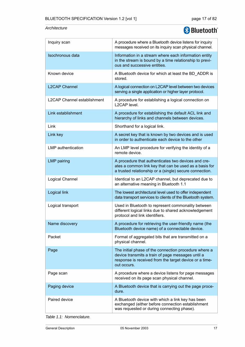
BLUETOOTH SPECIFICATION Version 1.2 [vol 1] page 17 of 82
Architecture
Inquiry scan A procedure where a Bluetooth device listens for inquiry messages received on its inquiry scan physical channel.
Isochronous data Information in a stream where each information entity in the stream is bound by a time relationship to previ-ous and successive entities.
Known device A Bluetooth device for which at least the BD_ADDR is stored.
L2CAP Channel A logical connection on L2CAP level between two devices serving a single application or higher layer protocol.
L2CAP Channel establishment A procedure for establishing a logical connection on L2CAP level.
Link establishment A procedure for establishing the default ACL link and hierarchy of links and channels between devices.
Link Shorthand for a logical link.
Link key A secret key that is known by two devices and is used in order to authenticate each device to the other
LMP authentication An LMP level procedure for verifying the identity of a remote device.
LMP pairing A procedure that authenticates two devices and cre-ates a common link key that can be used as a basis for a trusted relationship or a (single) secure connection.
Logical Channel Identical to an L2CAP channel, but deprecated due to an alternative meaning in Bluetooth 1.1
Logical link The lowest architectural level used to offer independent data transport services to clients of the Bluetooth system.
Logical transport Used in Bluetooth to represent commonality between different logical links due to shared acknowledgement protocol and link identifiers.
Name discovery A procedure for retrieving the user-friendly name (the Bluetooth device name) of a connectable device.
Packet Format of aggregated bits that are transmitted on a physical channel.
Page The initial phase of the connection procedure where a device transmits a train of page messages until a response is received from the target device or a time-out occurs.
Page scan A procedure where a device listens for page messages received on its page scan physical channel.
Paging device A Bluetooth device that is carrying out the page proce-dure.
Paired device A Bluetooth device with which a link key has been exchanged (either before connection establishment was requested or during connecting phase).
Table 1.1: Nomenclature.
General Description 05 November 2003 17

BLUETOOTH SPECIFICATION Version 1.2 [vol 1] page 18 of 82
Architecture
Parked device A device operating in a basic mode piconet that is syn-chronized to the master but has given up its default ACL logical transport.
Physical Channel Characterised by synchronized occupancy of a sequence of RF carriers by one or more devices. A number of physical channel types exist with character-istics defined for their different purposes.
Physical Link A Baseband-level connection between two devices established using paging.
Piconet A collection of devices occupying a shared physical channel where one of the devices is the Piconet Master and the remaining devices are connected to it.
Piconet Physical Channel A Channel that is divided into time slots in which each slot is related to an RF hop frequency. Consecutive hops normally correspond to different RF hop frequen-cies and occur at a standard hop rate of 1600 hops/s. These consecutive hops follow a pseudo-random hop-ping sequence, hopping through a 79 RF channel set.
Piconet Master The device in a piconet whose Bluetooth Clock and Bluetooth Device Address are used to define the pico-net physical channel characteristics.
Piconet Slave Any device in a piconet that is not the Piconet Master, but is connected to the Piconet Master.
PIN A user-friendly number that can be used to authenti-cate connections to a device before paring has taken place.
PMP A Participant in Multiple Piconets. A device that is con-currently a member of more than one piconet, which it achieves using time division multiplexing (TDM) to interleave its activity on each piconet physical channel.
The Parked Slave Broadcast (PSB)
The Parked Slave Broadcast logical transport that is used for communications between the master and parked devices. Section 3.5.8 on page 45.
Scatternet Two or more piconets that include one or more devices acting as PMPs.
Service Layer Protocol A protocol that uses an L2CAP channel for transporting PDUs.
Service discovery Procedures for querying and browsing for services offered by or through another Bluetooth device.
Silent device A Bluetooth device appears as silent to a remote device if it does not respond to inquiries made by the remote device.
Unknown device A Bluetooth device for which no information (Bluetooth Device Address, link key or other) is stored.
Table 1.1: Nomenclature.
18 05 November 2003 General Description

BLUETOOTH SPECIFICATION Version 1.2 [vol 1] page 19 of 82
Architecture
2 CORE SYSTEM ARCHITECTURE
The Bluetooth core system covers the four lowest layers and associated proto-cols defined by the Bluetooth specification as well as one common service layer protocol, the Service Discovery Protocol (SDP) and the overall profile requirements are specified in the Generic Access Profile (GAP). A complete Bluetooth application requires a number of additional service and higher layer protocols that are defined in the Bluetooth specification, but are not described here. The core system architecture is shown in Figure 2.1 on page 19 except for SDP that is not shown for clarity.
Figure 2.1: Bluetooth core system architecture
Figure 2.1 on page 19 shows the four lowest layers, each with its associated communication protocol. The lowest three layers are sometimes grouped into a subsystem known as the Bluetooth controller. This is a common implementa-tion involving a standard physical communications interface between the Blue-tooth controller and remainder of the Bluetooth system including the L2CAP, service and higher layers (known as the Bluetooth host.) Although this inter-face is optional the architecture is designed to allow for its existence and char-acteristics. The Bluetooth specification enables inter-operability between independent Bluetooth systems by defining the protocol messages exchanged between equivalent layers, and also inter-operability between independent
HCI
L2CAP
LMP
LC
U-plane and data traffic
C-plane and control
services
Protocol signalling
Blu
eto
oth
Co
ntr
oll
er
Radio
control controldata data
Synchronous
unframed traffic
Asynchronous and
isochronous framed traffic
Device
control
servicesL2CAPlayer
L2CAPResourceManager
ChannelManager
LinkManager
layer
Baseband ResourceManager
Radiolayer
LinkManager
DeviceManager
Basebandlayer
Link Controller
RF
Core System Architecture 05 November 2003 19

BLUETOOTH SPECIFICATION Version 1.2 [vol 1] page 20 of 82
Architecture
Bluetooth sub-systems by defining a common interface between Bluetooth controllers and Bluetooth hosts.
A number of functional blocks are shown and the path of services and data between these. The functional blocks shown in the diagram are informative; in general the Bluetooth specification does not define the details of implementa-tions except where this is required for inter-operability. Thus the functional blocks in Figure 2.1 on page 19 are shown in order to aid description of the system behaviour. An implementation may be different from the system shown in Figure 2.1 on page 19.
Standard interactions are defined for all inter-device operation, where Blue-tooth devices exchange protocol signalling according to the Bluetooth specifi-cation. The Bluetooth core system protocols are the Radio (RF) protocol, Link Control (LC) protocol, Link Manager (LM) protocol and Logical Link Control and Adaptation protocol (L2CAP), all of that are fully defined in subsequent parts of the Bluetooth specification. In addition the Service Discovery Protocol (SDP) is a service layer protocol required by all Bluetooth applications.
The Bluetooth core system offers services through a number of service access points that are shown in the diagram as ellipses. These services consist of the basic primitives that control the Bluetooth core system. The services can be split into three types. There are device control services that modify the behav-iour and modes of a Bluetooth device, transport control services that create, modify and release traffic bearers (channels and links), and data services that are used to submit data for transmission over traffic bearers. It is common to consider the first two as belonging to the C-plane and the last as belonging to the U-plane.
A service interface to the Bluetooth controller sub-system is defined such that the Bluetooth controller may be considered a standard part. In this configura-tion the Bluetooth controller operates the lowest three layers and the L2CAP layer is contained with the rest of the Bluetooth application in a host system. The standard interface is called the Host to Controller Interface (HCI) and its service access points are represented by the ellipses on the upper edge of the Bluetooth controller sub-system in Figure 2.1 on page 19. Implementation of this standard service interface is optional.
As the Bluetooth architecture is defined with the possibility of separate host and controller communicating through an HCI, a number of general assump-tions are made. The Bluetooth controller is assumed to have limited data buff-ering capabilities in comparison with the host. Therefore the L2CAP layer is expected to carry out some simple resource management when submitting L2CAP PDUs to the controller for transport to a peer device. This includes seg-mentation of L2CAP SDUs into more manageable PDUs and then the frag-mentation of PDUs into start and continuation packets of a size suitable for the controller buffers, and management of the use of controller buffers to ensure availability for channels with Quality of Service (QoS) commitments.
20 05 November 2003 Core System Architecture
BLUETOOTH SPECIFICATION Version 1.2 [vol 1] page 21 of 82
Architecture
The Baseband layer provides the basic ARQ protocol in Bluetooth. The L2CAP layer can optionally provide a further error detection and retransmission to the L2CAP PDUs. This feature is recommended for applications with requirements for a low probability of undetected errors in the user data. A further optional feature of L2CAP is a window-based flow control that can be used to manage buffer allocation in the receiving device. Both of these optional features aug-ment the QoS performance in certain scenarios.
Although these assumptions may not be required for embedded Bluetooth implementations that combine all layers in a single system, the general archi-tectural and QoS models are defined with these assumptions in mind, in effect a lowest common denominator.
Automated conformance testing of implementations of the Bluetooth core sys-tem is required. This is achieved by allowing the tester to control the implemen-tation through the RF interface, which is common to all Bluetooth systems, and through the Test Control Interface (TCI), which is only required for conform-ance testing.
The tester uses exchanges with the Implementation Under Test (IUT) through the RF interface to ensure the correct responses to requests from remote devices. The tester controls the IUT through the TCI to cause the IUT to origi-nate exchanges through the RF interface so that these can also be verified as conformant.
The TCI uses a different command-set (service interface) for the testing of each architectural layer and protocol. A subset of the HCI command-set is used as the TCI service interface for each of the layers and protocols within the Bluetooth Controller subsystem. A separate service interface is used for testing the L2CAP layer and protocol. As an L2CAP service interface is not defined in the Bluetooth core specification it is defined separately in the Test Control Inter-face specification. Implementation of the L2CAP service interface is only required for conformance testing.
Core System Architecture 05 November 2003 21

BLUETOOTH SPECIFICATION Version 1.2 [vol 1] page 22 of 82
Architecture
2.1 CORE ARCHITECTURAL BLOCKS
This section describes the function and responsibility of each of the blocks shown in Figure 2.1 on page 19. An implementation is not required to follow the architecture described above, though every implementation shall conform to the protocol specifications described in subsequent parts of the Bluetooth specification, and shall implement the behavioural aspects of the system out-lined below and specified in subsequent parts of the Bluetooth specification.
2.1.1 Channel manager
The channel manager is responsible for creating, managing and destroying L2CAP channels for the transport of service protocols and application data streams. The channel manager uses the L2CAP protocol to interact with a channel manager on a remote (peer) device to create these L2CAP channels and connect their endpoints to the appropriate entities. The channel manager interacts with its local link manager to create new logical links (if necessary) and to configure these links to provide the required quality of service for the type of data being transported.
2.1.2 L2CAP resource manager
The L2CAP resource manager block is responsible for managing the ordering of submission of PDU fragments to the baseband and some relative scheduling between channels to ensure that L2CAP channels with QoS commitments are not denied access to the physical channel due to Bluetooth controller resource exhaustion. This is required because the architectural model does not assume that the Bluetooth controller has limitless buffering, or that the HCI is a pipe of infinite bandwidth.
L2CAP Resource Managers may also carry out traffic conformance policing to ensure that applications are submitting L2CAP SDUs within the bounds of their negotiated QoS settings. The general Bluetooth data transport model assumes well-behaved applications, and does not define how an implementation is expected to deal with this problem.
22 05 November 2003 Core System Architecture

BLUETOOTH SPECIFICATION Version 1.2 [vol 1] page 23 of 82
Architecture
2.1.3 Device manager
The device manager is the functional block in the baseband that controls the general behaviour of the Bluetooth device. It is responsible for all operation of the Bluetooth system that is not directly related to data transport, such as inquiring for the presence of other nearby Bluetooth devices, connecting to other Bluetooth devices, or making the local Bluetooth device discoverable or connectable by other devices.
The device manager requests access to the transport medium from the base-band resource controller in order to carry out its functions.
The device manager also controls local device behaviour implied by a number of the HCI commands, such as managing the device local name, any stored link keys, and other functionality.
2.1.4 Link manager
The link manager is responsible for the creation, modification and release of logical links (and, if required, their associated logical transports), as well as the update of parameters related to physical links between devices. The link man-ager achieves this by communicating with the link manager in remote Blue-tooth devices using the Link Management Protocol (LMP.)
The LM protocol allows the creation of new logical links and logical transports between devices when required, as well as the general control of link and transport attributes such as the enabling of encryption on the logical transport, the adapting of transmit power on the physical link, or the adjustment of QoS settings for a logical link.
2.1.5 Baseband resource manager
The baseband resource manager is responsible for all access to the radio medium. It has two main functions. At its heart is a scheduler that grants time on the physical channels to all of the entities that have negotiated an access contract. The other main function is to negotiate access contracts with these entities. An access contract is effectively a commitment to deliver a certain QoS that is required in order to provide a user application with an expected performance.
The access contract and scheduling function must take account of any behav-iour that requires use of the Bluetooth radio. This includes (for example) the normal exchange of data between connected devices over logical links, and logical transports, as well as the use of the radio medium to carry out inquiries, make connections, be discoverable or connectable, or to take readings from unused carriers during the use of adaptive frequency hopping mode.
In some cases the scheduling of a logical link results in changing to a different physical channel from the one that was previously used. This may be (for example) due to involvement in scatternet, a periodic inquiry function, or page
Core System Architecture 05 November 2003 23
BLUETOOTH SPECIFICATION Version 1.2 [vol 1] page 24 of 82
Architecture
scanning. When the physical channels are not time slot aligned, then the resource manager also accounts for the realignment time between slots on the original physical channel and slots on the new physical channel. In some cases the slots will be naturally aligned due to the same device clock being used as a reference for both physical channels.
2.1.6 Link controller
The link controller is responsible for the encoding and decoding of Bluetooth packets from the data payload and parameters related to the physical channel, logical transport and logical link.
The link controller carries out the link control protocol signalling (in close con-junction with the scheduling function of the resource manager), which is used to communicate flow control and acknowledgement and retransmission request signals. The interpretation of these signals is a characteristic of the log-ical transport associated with the baseband packet. Interpretation and control of the link control signalling is normally associated with the resource manager’s scheduler.
2.1.7 RF
The RF block is responsible for transmitting and receiving packets of informa-tion on the physical channel. A control path between the baseband and the RF block allows the baseband block to control the timing and frequency carrier of the RF block. The RF block transforms a stream of data to and from the physi-cal channel and the baseband into required formats.
24 05 November 2003 Core System Architecture
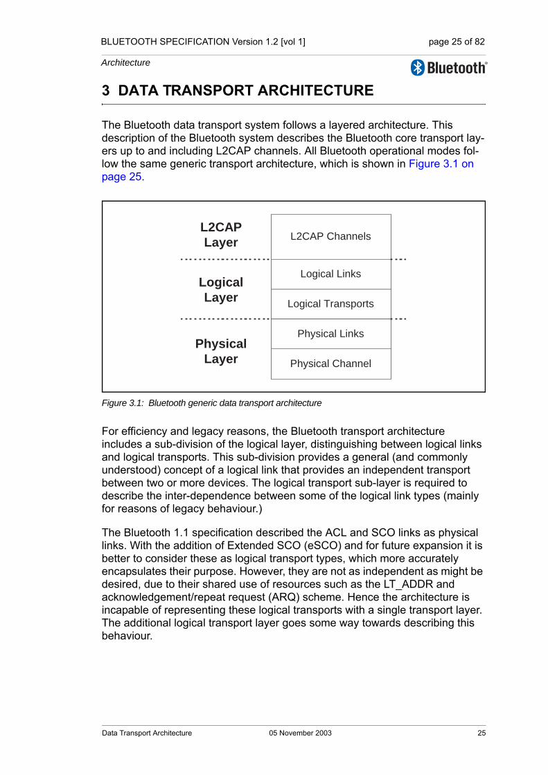
BLUETOOTH SPECIFICATION Version 1.2 [vol 1] page 25 of 82
Architecture
3 DATA TRANSPORT ARCHITECTURE
The Bluetooth data transport system follows a layered architecture. This description of the Bluetooth system describes the Bluetooth core transport lay-ers up to and including L2CAP channels. All Bluetooth operational modes fol-low the same generic transport architecture, which is shown in Figure 3.1 on page 25.
Figure 3.1: Bluetooth generic data transport architecture
For efficiency and legacy reasons, the Bluetooth transport architecture includes a sub-division of the logical layer, distinguishing between logical links and logical transports. This sub-division provides a general (and commonly understood) concept of a logical link that provides an independent transport between two or more devices. The logical transport sub-layer is required to describe the inter-dependence between some of the logical link types (mainly for reasons of legacy behaviour.)
The Bluetooth 1.1 specification described the ACL and SCO links as physical links. With the addition of Extended SCO (eSCO) and for future expansion it is better to consider these as logical transport types, which more accurately encapsulates their purpose. However, they are not as independent as might be desired, due to their shared use of resources such as the LT_ADDR and acknowledgement/repeat request (ARQ) scheme. Hence the architecture is incapable of representing these logical transports with a single transport layer. The additional logical transport layer goes some way towards describing this behaviour.
L2CAP Channels
Logical Links
Logical Transports
Physical Channel
Physical Links
L2CAP
Layer
Logical
Layer
Physical
Layer
Data Transport Architecture 05 November 2003 25

BLUETOOTH SPECIFICATION Version 1.2 [vol 1] page 26 of 82
Architecture
3.1 CORE TRAFFIC BEARERS
The Bluetooth core system provides a number of standard traffic bearers for the transport of service protocol and application data. These are shown in Fig-ure 3.2 on page 26 below (for ease of representation this is shown with higher layers to the left and lower layers to the right).
Figure 3.2: Bluetooth traffic bearers
The core traffic bearers that are available to applications are shown in Figure 3.2 on page 26 as the shaded rounded rectangles. The architectural layers that are defined to provide these services are described in Section 2 on page 19. A number of data traffic types are shown on the left of the diagram linked to the traffic bearers that are typically suitable for transporting that type of data traffic.
The logical links are named using the names of the associated logical transport and a suffix that indicates the type of data that is transported. (C for control links carrying LMP messages, U for L2CAP links carrying user data (L2CAP PDUs) and S for stream links carrying unformatted synchronous or isochro-nous data.) It is common for the suffix to be removed from the logical link with-out introducing ambiguity, thus a reference to the default ACL logical transport can be resolved to mean the ACL-C logical link in cases where the LMP proto-col is being discussed, or the ACL-U logical link when the L2CAP layer is being discussed.
The mapping of application traffic types to Bluetooth core traffic bearers in Fig-ure 3.2 on page 26 is based on matching the traffic characteristics with the
Application Bluetoothcore
Traffic Types
L2CAP
Channels
Logical
Links
Logical
Transports
Higher Layer
Protocol Signalling
Reliable
Asynchronous
Framed User Data
Higher Layer
Framed Isochronous
User Data
Constant Rate
Isochronous
User Data
Uneliable
Asynchronous
Framed User Data
Signalling
Unicast
Active Broadcast
Piconet Broadcast
Channel
ManagerLink Manager
ACL-C
ACL-U
ACL
ASB-U ASB
PSB-C
PSBPSB-U
SCO[-S]
ESCO[-S]
26 05 November 2003 Data Transport Architecture

BLUETOOTH SPECIFICATION Version 1.2 [vol 1] page 27 of 82
Architecture
bearer characteristics. It is recommended to use these mappings as they pro-vide the most natural and efficient method of transporting the data with its given characteristics.
However, an application (or an implementation of the Bluetooth core system) may choose to use a different traffic bearer, or a different mapping to achieve a similar result. For example, in a piconet with only one slave, the master may choose to transport L2CAP broadcasts over the ACL-U logical link rather than over the ASB-U or PSB-U logical links. This will probably be more efficient in terms of bandwidth (if the physical channel quality is not too degraded.) Use of alternative transport paths to those in Figure 3.2 on page 26 is only acceptable if the characteristics of the application traffic type are preserved.
Figure 3.2 on page 26 shows a number of application traffic types. These are used to classify the types of data that may be submitted to the Bluetooth core system. The original data traffic type may not be the same as the type that is submitted to the Bluetooth core system if an intervening process modifies it. For example, video data is generated at a constant rate but an intermediate coding process may alter this to variable rate, e.g. by MPEG4 encoding. For the purposes of the Bluetooth core system, only the characteristic of the sub-mitted data is of interest.
3.1.1 Framed data traffic
The L2CAP layer services provide a frame-oriented transport for asynchronous and isochronous user data. The application submits data to this service in vari-able-sized frames (up to a negotiated maximum for the channel) and these frames are delivered in the same form to the corresponding application on the remote device. There is no requirement for the application to insert additional framing information into the data, although it may do so if this is required (such framing is invisible to the Bluetooth core system.)
Connection-oriented L2CAP channels may be created for transport of unicast (point-to-point) data between two Bluetooth devices. A connectionless L2CAP channel exists for broadcasting data. In the case of piconet topologies the mas-ter device is always the source of broadcast data and the slave device(s) are the recipients. Traffic on the broadcast L2CAP channel is uni-directional. Uni-cast L2CAP channels may be uni-directional or bi-directional.
L2CAP channels have an associated QoS setting that defines constraints on the delivery of the frames of data. These QoS settings may be used to indicate (for example) that the data is isochronous, and therefore has a limited lifetime after which it becomes invalid, or that the data should be delivered within a given time period, or that the data is reliable and should be delivered without error, however long this takes.
The L2CAP channel manager is responsible for arranging to transport the L2CAP channel data frames on an appropriate baseband logical link, possibly multiplexing this onto the baseband logical link with other L2CAP channels with similar characteristics.
Data Transport Architecture 05 November 2003 27
BLUETOOTH SPECIFICATION Version 1.2 [vol 1] page 28 of 82
Architecture
3.1.2 Unframed data traffic
If the application does not require delivery of data in frames, possibly because it includes in-stream framing, or because the data is a pure stream, then it may avoid the use of L2CAP channels and make direct use of a baseband logical link.
The Bluetooth core system supports the direct transport of application data that is isochronous and of a constant rate (either bit-rate, or frame-rate for pre-framed data), using a SCO-S or eSCO-S logical link. These logical links reserve physical channel bandwidth and provide a constant rate transport locked to the piconet clock. Data is transported in fixed size packets at fixed intervals with both of these parameters negotiated during channel establish-ment. eSCO links provide a greater choice of bit-rates and also provide greater reliability by using limited retransmission in case of error. SCO and eSCO logi-cal transports do not support multiplexed logical links or any further layering within the Bluetooth core. An application may choose to layer a number of streams within the submitted SCO/eSCO stream, provided that the submitted stream is, or has the appearance of being, a constant rate stream.
The application chooses the most appropriate type of logical link from those available at the baseband, and creates and configures it to transport the data stream, and releases it when completed. (The application will normally also use a framed L2CAP unicast channel to transport its C-plane information to the peer application on the remote device.)
If the application data is isochronous and of a variable rate, then this may only be carried by the L2CAP unicast channel, and hence will be treated as framed data.
3.1.3 Reliability of traffic bearers
Bluetooth is a wireless communications system. In poor RF environments, this system should be considered inherently unreliable. To counteract this the sys-tem provides levels of protection at each layer. The baseband packet header uses forward error correcting (FEC) coding to allow error correction by the receiver and a header error check (HEC) to detect errors remaining after cor-rection. Certain Baseband packet types include FEC for the payload. Further-more, some Baseband packet types include a cyclic redundancy error check (CRC).
On ACL logical transports the results of the error detection algorithm are used to drive a simple acknowledgement/repeat request (ARQ) protocol. This pro-vides an enhanced reliability by re-transmitting packets that do not pass the receiver’s error checking algorithm. It is possible to modify this scheme to sup-port latency-sensitive packets by discarding an unsuccessfully transmitted packet at the transmitter if the packet’s useful life has expired. eSCO links use a modified version of this scheme to improve reliability by allowing a limited number of retransmissions.
28 05 November 2003 Data Transport Architecture
BLUETOOTH SPECIFICATION Version 1.2 [vol 1] page 29 of 82
Architecture
The resulting reliability gained by this ARQ scheme is only as dependable as the ability of the HEC and CRC codes to detect errors. In most cases this is sufficient, however it has been shown that for the longer packet types the prob-ability of an undetected error is too high to support typical applications, espe-cially those with a large amount of data being transferred.
The L2CAP layer provides an additional level of error control that is designed to detect the occasional undetected errors in the baseband layer and request retransmission of the affected data. This provides the level of reliability required by typical Bluetooth applications.
Broadcast links have no feedback route, and are unable to use the ARQ scheme (although the receiver is still able to detect errors in received packets.) Instead each packet is transmitted several times in the hope that the receiver is able to receive at least one of the copies successfully. Despite this approach there are still no guarantees of successful receipt, and so these links are con-sidered unreliable.
In summary, if a link or channel is characterised as reliable this means that the receiver is capable of detecting errors in received packets and requesting re-transmission until the errors are removed. Due to the error detection system used some residual (undetected) errors may still remain in the received data. For L2CAP channels the level of these is comparable to other communication systems, although for logical links the residual error level is somewhat higher.
The transmitter may remove packets from the transmit queue such that the receiver does not receive all the packets in the sequence. If this happens detection of the missing packets is delegated to the L2CAP layer.
On an unreliable link the receiver is capable of detecting errors in received packets but cannot request retransmission. The packets passed on by the receiver may be without error, but there is no guarantee that all packets in the sequence are received. Hence the link is considered fundamentally unreliable. There are limited uses for such links, and these uses are normally dependent on the continuous repetition of data from the higher layers while it is valid.
Stream links have a reliability characteristic somewhere between a reliable and an unreliable link, depending on the current operating conditions.
Data Transport Architecture 05 November 2003 29
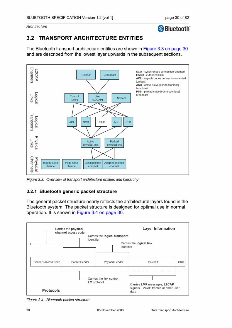
BLUETOOTH SPECIFICATION Version 1.2 [vol 1] page 30 of 82
Architecture
3.2 TRANSPORT ARCHITECTURE ENTITIES
The Bluetooth transport architecture entities are shown in Figure 3.3 on page 30 and are described from the lowest layer upwards in the subsequent sections.
Figure 3.3: Overview of transport architecture entities and hierarchy
3.2.1 Bluetooth generic packet structure
The general packet structure nearly reflects the architectural layers found in the Bluetooth system. The packet structure is designed for optimal use in normal operation. It is shown in Figure 3.4 on page 30.
Figure 3.4: Bluetooth packet structure
Inquiry scan
channel
Page scan
channel
Basic piconet
channel
Adapted piconet
channel
Active
physical link
Parked
physical link
SCO ASB PSBACL ESCO
Control
(LMP)
User
(L2CAP)Stream
Ph
ysic
al
Ch
an
ne
ls
Ph
ysic
al
Lin
ks
Lo
gic
al
Tra
nsp
orts
Lo
gic
al
Lin
ks
Unicast Broadcast
L2
CA
P
Ch
an
ne
ls
SCO - synchronous connection-oriented
ESCO - extended SCO
ACL - asynchronous connection-oriented
[unicast]
ASB - active slave [connectionless]
broadcast
PSB - parked slave [connectionless]
broadcast
Layer Information
Protocols
Carries the physical
channel access codeCarries the logical transport
identifierCarries the logical link
identifier
Carries the link control
LC protocolCarries LMP messages, L2CAP
signals, L2CAP frames or other user
data
Channel Access Code Packet Header Payload Header Payload CRC
30 05 November 2003 Data Transport Architecture

BLUETOOTH SPECIFICATION Version 1.2 [vol 1] page 31 of 82
Architecture
Packets normally only include the fields that are necessary to represent the layers required by the transaction. Thus a simple inquiry request over an inquiry scan physical channel does not create or require a logical link or higher layer and therefore consists only of the channel access code (associated with the physical channel.) General communication within a piconet uses packets that include all of the fields, as all of the architectural layers are used.
All packets include the channel access code. This is used to identify communi-cations on a particular physical channel, and to exclude or ignore packets on a different physical channel that happens to be using the same RF carrier in physical proximity.
There is no direct field within the Bluetooth packet structure that represents or contains information relating to physical links. This information is implied in the logical transport address (LT_ADDR) carried in the packet header.
Most packets include a packet header. The packet header is always present in packets transmitted on physical channels that support physical links, logical transports and logical links. The packet header carries the LT_ADDR, which is used by each receiving device to determine if the packet is addressed to the device and is used to route the packet internally.
The packet header also carries part of the link control (LC) protocol that is operated per logical transport (except for ACL and SCO transports that operate a shared LC protocol carried on either logical transport.)
The payload header is present in all packets on logical transports that support multiple logical links. The payload header includes a logical link identifier field used for routing the payload, and a field indicating the length of the payload. Some packet types also include a CRC after the packet payload that is used to detect most errors in received packets.
The packet payload is used to transport the user data. The interpretation of this data is dependent on the logical transport and logical link identifiers. For ACL logical transports Link Manager Protocol (LMP) messages and L2CAP signals are transported in the packet payload, along with general user data from appli-cations. For SCO and eSCO logical transports the payload contains the user data for the logical link.
Data Transport Architecture 05 November 2003 31

BLUETOOTH SPECIFICATION Version 1.2 [vol 1] page 32 of 82
Architecture
3.3 PHYSICAL CHANNELS
The lowest architectural layer in the Bluetooth system is the physical channel. A number of types of physical channel are defined. All Bluetooth physical chan-nels are characterised by an RF frequency combined with temporal parameters and restricted by spatial considerations. For the basic and adapted piconet physical channels frequency hopping is used to change frequency periodically to reduce the effects of interference and for regulatory reasons.
Two Bluetooth devices use a shared physical channel for communication. To achieve this their transceivers need to be tuned to the same RF frequency at the same time, and they need to be within a nominal range of each other.
Given that the number of RF carriers is limited and that many Bluetooth devices may be operating independently within the same spatial and temporal area there is a strong likelihood of two independent Bluetooth devices having their transceivers tuned to the same RF carrier, resulting in a physical channel collision. To mitigate the unwanted effects of this collision each transmission on a physical channel starts with an access code that is used as a correlation code by devices tuned to the physical channel. This channel access code is a property of the physical channel. The access code is always present at the start of every transmitted packet.
Four Bluetooth physical channels are defined. Each is optimised and used for a different purpose. Two of these physical channels (the basic piconet channel and adapted piconet channel) are used for communication between connected devices and are associated with a specific piconet. The remaining physical channels are used for discovering Bluetooth devices (the inquiry scan channel) and for connecting Bluetooth devices (the page scan channel.)
A Bluetooth device can only use one of these physical channels at any given time. In order to support multiple concurrent operations the device uses time-division multiplexing between the channels. In this way a Bluetooth device can appear to operate simultaneously in several piconets, as well as being discov-erable and connectable.
Whenever a Bluetooth device is synchronized to the timing, frequency and access code of a physical channel it is said to be ‘connected’ to this channel (whether or not it is actively involved in communications over the channel.) The Bluetooth specification assumes that a device is only capable of connecting to one physical channel at any time. Advanced devices may capable of connect-ing simultaneously to more than one physical channel, but the specification does not assume that this is possible.
32 05 November 2003 Data Transport Architecture

BLUETOOTH SPECIFICATION Version 1.2 [vol 1] page 33 of 82
Architecture
3.3.1 Basic piconet channel
3.3.1.1 Overview
The basic piconet channel is used for communication between connected devices during normal operation.
3.3.1.2 Characteristics
The basic piconet channel is characterised by a pseudo-random sequence hopping through the RF channels. The hopping sequence is unique for the piconet and is determined by the Bluetooth device address of the master. The phase in the hopping sequence is determined by the Bluetooth clock of the master. All Bluetooth devices participating in the piconet are time- and hop-syn-chronized to the channel.
The channel is divided into time slots where each slot corresponds to an RF hop frequency. Consecutive hops correspond to different RF hop frequencies. The time slots are numbered according to the Bluetooth clock of the piconet master. Packets are transmitted by Bluetooth devices participating in the piconet aligned to start at a slot boundary. Each packet starts with the channel’s access code, which is derived from the Bluetooth device address of the piconet.
On the basic piconet channel the master controls access to the channel. The master starts its transmission in even-numbered time slots only. Packets trans-mitted by the master are aligned with the slot start and define the piconet tim-ing. Packets transmitted by the master may occupy up to five time slots depending on the packet type.
Each master transmission is a packet carrying information on one of the logical transports. Slave devices may transmit on the physical channel in response. The characteristics of the response are defined by the logical transport that is addressed.
For example on the asynchronous connection-oriented logical transport the addressed slave device responds by transmitting a packet containing informa-tion for the same logical transport that is nominally aligned with the next (odd-numbered) slot start. Such a packet may occupy up to five time slots, depend-ing on the packet type. On a broadcast logical transport no slaves are allowed to respond.
A special characteristic of the basic piconet physical channel is the use of some reserved slots to transmit a beacon train. The beacon train is only used if the piconet physical channel has parked slaves connected to it. In this situation the master transmits a packet in the reserved beacon train slots (these packets are used by the slave to resynchronize to the piconet physical channel.) The master may transmit packets from any logical transport onto these slots, pro-viding there is a transmission starting in each of the slots. In the case where
Data Transport Architecture 05 November 2003 33

BLUETOOTH SPECIFICATION Version 1.2 [vol 1] page 34 of 82
Architecture
there is information from the parked slave broadcast (PSB) logical transport to be transmitted then this is transmitted in the beacon train slots and takes prior-ity over any other logical transport.
3.3.1.3 Topology
A basic piconet channel may be shared by any number of Bluetooth devices, limited only by the resources available on the piconet master device. Only one device is the piconet master, all others being piconet slaves. All communication is between the master and slave devices. There is no direct communication between slave devices on the piconet channel.
There is, however, a limitation on the number of logical transports that can be supported within a piconet. This means that although there is no theoretical limit to the number of Bluetooth devices that share a channel there is a limit to the number of these devices that can be actively involved in exchanging data with the master.
3.3.1.4 Supported layers
The basic piconet channel supports a number of physical links, logical trans-ports, logical links and L2CAP channels used for general purpose communica-tions.
3.3.2 Adapted piconet channel
3.3.2.1 Overview
The adapted piconet channel differs from the basic piconet channel in two ways. First the frequencies on which the slaves transmit are the same as the preceding master transmit frequency. In other words the frequency is not recomputed between master and subsequent slave packets. The second way in which the adapted piconet channel differs from the basic piconet channel is that the adapted type can be based on fewer than the full 79 frequencies. A number of frequencies may be excluded from the hopping pattern by being marked as “unused”. The remainder of the 79 frequencies are included. The two sequences are the same except that whenever the basic pseudo-random hopping sequence would have selected an unused frequency it is replaced with an alternative chosen from the used set.
Because the adapted piconet channel uses the same timing and access code as the basic piconet channel, the two channels are often coincident. This pro-vides a deliberate benefit as it allows slaves in either the basic piconet channel or the adapted piconet channel to adjust their synchronization to the master.
The topology and supported layers of the adapted piconet physical channel are identical to the basic piconet physical channel.
34 05 November 2003 Data Transport Architecture

BLUETOOTH SPECIFICATION Version 1.2 [vol 1] page 35 of 82
Architecture
3.3.3 Inquiry scan channel
3.3.3.1 Overview
In order for a device to be discovered an inquiry scan channel is used. A dis-coverable device listens for inquiry requests on its inquiry scan channel and then sends responses to these requests. In order for a device to discover other devices, it iterates (hops) through all possible inquiry scan channel frequencies in a pseudo-random fashion, sending an inquiry request on each frequency and listening for any response.
3.3.3.2 Characteristics
Inquiry scan channels follow a slower hopping pattern and use an access code to distinguish between occasional occupancy of the same radio frequency by two co-located devices using different physical channels.
The access code used on the inquiry scan channel is taken from a reserved set of inquiry access codes that are shared by all Bluetooth devices. One access code is used for general inquiries, and a number of additional access codes are reserved for limited inquiries. Each device has access to a number of differ-ent inquiry scan channels. As all of these channels share an identical hopping pattern, a device may concurrently occupy more than one inquiry scan channel if it is capable of concurrently correlating more than one access code.
A device using one of its inquiry scan channel remains passive until it receives an inquiry message on this channel from another Bluetooth device. This is identified by the appropriate inquiry access code. The inquiry scanning device will then follow the inquiry response procedure to return a response to the inquiring device.
In order for a device to discover other Bluetooth devices it uses the inquiry scan channel of these devices in order to send inquiry requests. As it has no prior knowledge of the devices to discover, it cannot know the exact character-istics of the inquiry scan channel.
The device takes advantage of the fact that inquiry scan channels have a reduced number of hop frequencies and a slower rate of hopping. The inquiring device transmits inquiry requests on each of the inquiry scan hop frequencies and listens for an inquiry response. This is done at a faster rate, allowing the inquiring device to cover all inquiry scan frequencies in a reasonably short time period.
Data Transport Architecture 05 November 2003 35
BLUETOOTH SPECIFICATION Version 1.2 [vol 1] page 36 of 82
Architecture
3.3.3.3 Topology
Inquiring and discoverable devices use a simple exchange of packets to fulfil the inquiring function. The topology formed during this transaction is a simple and transient point-to-point connection.
3.3.3.4 Supported layers
During the exchange of packets between an inquiring and discoverable device it may be considered that a temporary physical link exists between these devices. However, the concept is quite irrelevant as it has no physical repre-sentation but is only implied by the brief transaction between the devices. No further architectural layers are considered to be supported.
3.3.4 Page scan channel
3.3.4.1 Overview
A connectable device (one that is prepared to accept connections) does so using an page scan channel. A connectable device listens for page requests on its page scan channel and enters into a sequence of exchanges with this device. In order for a device to connect to another device, it iterates (hops) through all page scan channel frequencies in a pseudo-random fashion, send-ing an page request on each frequency and listening for any response.
3.3.4.2 Characteristics
The page scan channel uses an access code derived from the scanning device’s Bluetooth device address to identify communications on the channel. The page scan channel uses a slower hopping rate than the hop rate of the basic and adapted piconet channels. The hop selection algorithm uses the Bluetooth device clock of the scanning device as an input.
A device using its page scan channel remains passive until it receives a page request from another Bluetooth device. This is identified by the page scan channel access code. The two devices will then follow the page procedure to form a connection. Following a successful conclusion of the page procedure both devices switch to the basic piconet channel that is characterised by hav-ing the paging device as master.
In order for a device to connect to another Bluetooth device it uses the page scan channel of the target device in order to send page requests. If the paging device does not know the phase of the target device’s page scan channel it therefore does not know the current hop frequency of the target device. The paging device transmits page requests on each of the page scan hop frequen-cies and listens for a page response. This is done at a faster hop rate, allowing
36 05 November 2003 Data Transport Architecture

BLUETOOTH SPECIFICATION Version 1.2 [vol 1] page 37 of 82
Architecture
the paging device to cover all page scan frequencies in a reasonably short time period.
The paging device may have some knowledge of the target device’s Bluetooth clock (indicated during a previous inquiry transaction between the two devices, or as a result of a previous involvement in a piconet with the device), in which case it is able to predict the phase of the target device’s page scan channel. It may use this information to optimise the synchronization of the paging and page scanning process and speed up the formation of the connection.
3.3.4.3 Topology
Paging and connectable devices use a simple exchange of packets to fulfil the paging function. The topology formed during this transaction is a simple and transient point-to-point connection.
3.3.4.4 Supported layers
During the exchange of packets between an paging and connectable device it may be considered that a temporary physical link exists between these devices. However, the concept is quite irrelevant as it has no physical repre-sentation but is only implied by the brief transaction between the devices. No further architectural layers are considered to be supported.
3.4 PHYSICAL LINKS
A physical link represents a baseband connection between Bluetooth devices. A physical link is always associated with exactly one physical channel (although a physical channel may support more than one physical link.)
Within the Bluetooth system a physical link is a virtual concept that has no direct representation within the structure of a transmitted packet. The access code packet field, together with the clock and address of the master Bluetooth device are used to identify a physical channel. However there is no subsequent part of the packet that directly identifies the physical link. Instead the physical link may be identified by association with the logical transport, as each logical transport is only received on one physical link.
Some physical link types have properties that may be modified. An example of this is the transmit power for the link. Other physical link types have no such properties. In the case of physical links with modifiable properties the LM proto-col is used to adapt these properties. As the LM protocol is supported at a higher layer (by a logical link) the appropriate physical link is identified by impli-cation from the logical link that transports the LM signalling.
In the situation where a transmission is broadcasted over a number of different physical links, then the transmission parameters are selected to be suitable for all of the physical links.
Data Transport Architecture 05 November 2003 37
BLUETOOTH SPECIFICATION Version 1.2 [vol 1] page 38 of 82
Architecture
3.4.1 Links supported by the basic and adapted piconet physical channel
The basic and adapted piconet physical channels support a physical link which may be active or parked. The physical link is a point-to-point link between the master and a slave. It is always present when the slave is synchronized in the piconet.
3.4.1.1 Active physical link
The physical link between a master and a slave device is active if a default ACL logical transport exists between the devices. Active physical links have no direct identification of their own, but are identified by association with the default ACL logical transport ID with which there is a one-to-one correspondence.
An active physical link has the associated properties of radio transmit power in each direction. Transmissions from slave devices are always directed over the active physical link to the master, and use the transmit power that is a property of this link in the slave to master direction. Transmissions from the master may be directed over a single active physical link (to a specific slave) or over a num-ber of physical links (to a group of slaves in the piconet.) In the case of point-to-point transmissions the master uses the appropriate transmit power for the physical link in question. (In the case of point-to-multipoint transmissions the master uses a transmit power appropriate for the set of devices addressed.)
Active physical links may be placed into hold or sniff mode. The effect of these modes is to modify the periods when the physical link is active and may carry traffic. Logical transports that have defined scheduling characteristics are not affected by these modes and continue according to their pre-defined scheduling behaviour. The default ACL logical transport and other links with undefined scheduling characteristics are subject to the mode of the active physical link.
3.4.1.2 Parked physical link
The physical link between a master and a slave device is parked when the slave remains synchronized in the piconet, but has no default ACL logical transport. Such a slave is also said to be parked. A beacon train is used to pro-vide regular synchronization to all parked slaves connected to the piconet physical channel. A parked slave broadcast (PSB) logical transport is used to allow communication of a subset of LMP signalling and broadcast L2CAP to parked slaves. The PSB logical transport is closely associated with the beacon train.
A slave is parked (its active link is changed to a parked link) using the park pro-cedure. The master is not allowed to park a slave that has any user created logical transport supported by the physical link. These logical transports are first removed, and any L2CAP channels that are built on these logical trans-ports are also removed. The broadcast logical transport and default ACL logi-cal transports are not considered as user created and are not explicitly removed. When the active link is replaced with a parked link the default ACL
38 05 November 2003 Data Transport Architecture

BLUETOOTH SPECIFICATION Version 1.2 [vol 1] page 39 of 82
Architecture
logical transport is implicitly removed. The supported logical links and L2CAP channels remain in existence, but become suspended. It is not possible to use these links and L2CAP channels to transport signalling or data while the active link is absent.
A parked slave may become active using the unpark procedure. This proce-dure is requested by the slave at an access window and initiated by the mas-ter. Following the unpark procedure the parked physical link is changed to an active physical link and the default ACL logical transport is re-created. L2CAP channels that were suspended during the most recent park procedure are associated with the new default ACL logical transport and become active again.
Parked links do not support radio power control, as there is no feedback path from parked slaves to the piconet master that can be used to signal received signal strength at the slave or for the master to measure received signal strength from the slave. Transmissions are carried out at nominal power on parked links.
Parked links use the same physical channel as their associated active link. If a master manages a piconet that contains parked slaves using the basic piconet physical channel and also parked slaves using the adapted piconet physical channel then it must create a parked slave broadcast logical transport (and associated transport) for each of these physical channels.
A parked slave may use the inactive periods of the parked slave broadcast log-ical transport to save power, or it may carry out activities on other physical channels unrelated to the piconet within which it is parked.
3.4.2 Links supported by the scanning physical channels
In the case of the inquiry scan and page scan channels the physical link exists for a relatively short time and cannot be controlled or modified in any way. These types of physical link are not further elaborated.
3.5 LOGICAL LINKS AND LOGICAL TRANSPORTS
A variety of logical links are available to support different application data trans-port requirements. Each logical link is associated with a logical transport, which has a number of characteristics. These characteristics include flow control, acknowledgement/repeat mechanisms, sequence numbering and scheduling behaviour. Logical transports are able to carry different types of logical links (depending on the type of the logical transport). In the case of some of the Bluetooth 1.1 logical links these are multiplexed onto the same logical trans-port. Logical transports may be carried by active physical links on either the basic or the adapted piconet physical channel.
Logical transport identification and real-time (link control) signalling are carried in the packet header, and for some logical links identification is carried in the
Data Transport Architecture 05 November 2003 39
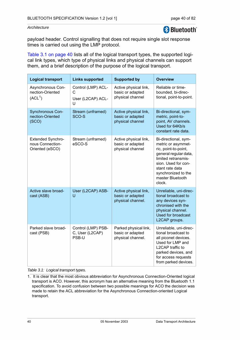
BLUETOOTH SPECIFICATION Version 1.2 [vol 1] page 40 of 82
Architecture
payload header. Control signalling that does not require single slot response times is carried out using the LMP protocol.
Table 3.1 on page 40 lists all of the logical transport types, the supported logi-cal link types, which type of physical links and physical channels can support them, and a brief description of the purpose of the logical transport.
Logical transport Links supported Supported by Overview
Asynchronous Con-nection-Oriented (ACL1)
1. It is clear that the most obvious abbreviation for Asynchronous Connection-Oriented logical transport is ACO. However, this acronym has an alternative meaning from the Bluetooth 1.1 specification. To avoid confusion between two possible meanings for ACO the decision was made to retain the ACL abbreviation for the Asynchronous Connection-oriented Logical transport.
Control (LMP) ACL-CUser (L2CAP) ACL-U
Active physical link, basic or adapted physical channel
Reliable or time-bounded, bi-direc-tional, point-to-point.
Synchronous Con-nection-Oriented (SCO)
Stream (unframed) SCO-S
Active physical link, basic or adapted physical channel
Bi-directional, sym-metric, point-to-point, AV channels. Used for 64Kb/s constant rate data.
Extended Synchro-nous Connection-Oriented (eSCO)
Stream (unframed) eSCO-S
Active physical link, basic or adapted physical channel
Bi-directional, sym-metric or asymmet-ric, point-to-point, general regular data, limited retransmis-sion. Used for con-stant rate data synchronized to the master Bluetooth clock.
Active slave broad-cast (ASB)
User (L2CAP) ASB-U
Active physical link, basic or adapted physical channel.
Unreliable, uni-direc-tional broadcast to any devices syn-chronised with the physical channel. Used for broadcast L2CAP groups.
Parked slave broad-cast (PSB)
Control (LMP) PSB-C, User (L2CAP) PSB-U
Parked physical link, basic or adapted physical channel.
Unreliable, uni-direc-tional broadcast to all piconet devices. Used for LMP and L2CAP traffic to parked devices, and for access requests from parked devices.
Table 3.1: Logical transport types.
40 05 November 2003 Data Transport Architecture
BLUETOOTH SPECIFICATION Version 1.2 [vol 1] page 41 of 82
Architecture
The names given to the logical links and logical transports reflect some of the names used in Bluetooth 1.1, in order to provide some degree of familiarity and continuation. However these names do not reflect a consistent scheme, which is outlined below.
The classification of each link type follows from a selection procedure within three categories.
3.5.1 Casting
The first category is that of casting. This may be either unicast or broadcast. There are no multicast links defined in Bluetooth 1.2,
• Unicast links. Unicast links exist between exactly two endpoints. Traffic may be sent in either direction on unicast links. All unicast links are connection-oriented, meaning that a connection procedure takes place before the link may be used. In the case of the default ACL links, the connection procedure is an implicit step within the general paging procedure used to form ad-hoc piconets.
• Broadcast links. Broadcast links exist between one source device and zero or more receiver devices. Traffic is unidirectional, i e only sent from the source devices to the receiver devices. Broadcast links are connectionless, meaning that there is no procedure to create these links, and data may be sent over them at any time. Broadcast links are unreliable, and there is no guarantee that the data will be received.
3.5.2 Scheduling and acknowledgement scheme
The second category relates to the scheduling and acknowledgement scheme of the link, and implies the type of traffic that is supported by the link. These are synchronous, isochronous or asynchronous. There are no specific isochronous links defined in Bluetooth 1.2, though the default ACL link can be configured to operate in this fashion.
• Synchronous links. Synchronous links provide a method of associating the Bluetooth piconet clock with the transported data. This is achieved by reserving regular slots on the physical channel, and transmitting fixed size packets at these regular intervals. Such links are suitable for constant rate isochronous data.
• Asynchronous links. Asynchronous links provide a method for transporting data that has no time-based characteristics. The data is normally expected to be retransmitted until successfully received, and each data entity can be processed at any time after receipt, without reference to the time of receipt of any previous or successive entity in the stream (providing the ordering of data entities is preserved.)
• Isochronous links. Isochronous links provide a method for transporting data that has time-based characteristics. The data may be retransmitted until received or expired. The data rate on the link need not be constant (this being the main difference from synchronous links.)
Data Transport Architecture 05 November 2003 41

BLUETOOTH SPECIFICATION Version 1.2 [vol 1] page 42 of 82
Architecture
3.5.3 Class of data
The final category is related to the class of data that is carried by the link. This is either control (LMP) data or user data. The user data category is sub-divided into L2CAP (or framed) data and stream (or unframed) data.
• Control links. Control links are only used for transporting LMP messages between two link managers. These links are invisible above the baseband layer, and cannot be directly instantiated, configured or released by applica-tions, other than by the use of the connection and disconnection services that have this effect implicitly. Control links are always multiplexed with an equivalent L2CAP link onto an ACL logical transport. Subject to the rules defining the ARQ scheme, the control link traffic always takes priority over the L2CAP link traffic.
• L2CAP links. L2CAP links are used to transport L2CAP PDUs, which may carry the L2CAP signalling channel (on the default ACL-U logical link only) or framed user data submitted to user-instantiated L2CAP channels. L2CAP frames submitted to the baseband may be larger than the available base-band packets. A link control protocol embedded within the LLID field pre-serves the frame-start and frame-continuation semantics when the frame is transmitted in a number of fragments to the receiver.
• Stream links. Stream links are used to transport user data that has no inher-ent framing that should be preserved when delivering the data. Lost data may be replaced by padding at the receiver.
3.5.4 Asynchronous connection-oriented (ACL)
The asynchronous connection-oriented (ACL) logical transport is used to carry LMP and L2CAP control signalling and best effort asynchronous user data. The ACL logical transport uses a simple 1-bit ARQN/SEQN scheme to provide sim-ple channel reliability. Every active slave device within a piconet has one ACL logical transport to the piconet master, known as the default ACL.
The default ACL is created between the master and the slave when a device joins a piconet (connects to the basic piconet physical channel). This default ACL is assigned a logical transport address (LT_ADDR) by the piconet master. This LT_ADDR is also used to identify the active physical link when required (or as a piconet active member identifier, effectively for the same purpose.)
The LT_ADDR for the default ACL is reused for synchronous connection-ori-ented logical transports between the same master and slave. (This is for rea-sons of compatibility with earlier Bluetooth specifications.) Thus the LT_ADDR is not sufficient on its own to identify the default ACL. However the packet types used on the ACL are different from those used on the synchronous con-nection-oriented logical transport. Therefore, the ACL logical transport can be identified by the LT_ADDR field in the packet header in combination with the packet type field.
42 05 November 2003 Data Transport Architecture
BLUETOOTH SPECIFICATION Version 1.2 [vol 1] page 43 of 82
Architecture
The default ACL may be used for isochronous data transport by configuring it to automatically flush packets after the packets have expired.
If the default ACL is removed from the active physical link then all other logical transports that exist between the master and the slave are also removed. In the case of unexpected loss of synchronization to the piconet physical channel the physical link and all logical transports and logical links cease to exist at the time that this synchronization loss is detected.
A device may remove its default ACL (and by implication its active physical link) but remain synchronized to the piconet. This procedure is known as park-ing, and a device that is synchronized to the piconet, but has no active physical link is parked within that piconet.
When the device transitions to the parked state the default ACL logical links that are transported on the default ACL logical transport remain in existence, but become suspended. No data may be transferred across a suspended logi-cal link. When the device transitions from the parked state back into active state, a new default ACL logical transport is created (it may have a different LT_ADDR from the previous one) and the suspended logical links are attached to this default ACL and become active once again.
3.5.5 Synchronous connection-oriented (SCO)
The synchronous connection-oriented (SCO) logical transport is a symmetric, point-to-point channel between the master and a specific slave. The SCO logi-cal transport reserves slots on the physical channel and can therefore be con-sidered as a circuit-switched connection between the master and the slave. SCO logical transports carry 64 kb/s of information synchronized with the pico-net clock. Typically this information is an encoded voice stream. Three different SCO configurations exist, offering a balance between robustness, delay and bandwidth consumption.
Each SCO-S logical link is supported by a single SCO logical transport, which is assigned the same LT_ADDR as the default ACL logical transport between the devices. Therefore the LT_ADDR field is not sufficient to identify the desti-nation of a received packet. Because the SCO links use reserved slots, a device uses a combination of the LT_ADDR, the slot numbers (a property of the physical channel) and the packet type to identify transmissions on the SCO link.
The reuse of the default ACL’s LT_ADDR for SCO logical transports is due to legacy behaviour from the Bluetooth 1.1 specification. In this earlier version of Bluetooth the LT_ADDR (then known as the active member address) was used to identify the piconet member associated with each transmission. This was not easily extensible for enabling more logical links, and so the purpose of this field was redefined for the new features. Some Bluetooth 1.1 features, however, do not cleanly fit into the more formally described architecture.
Data Transport Architecture 05 November 2003 43
BLUETOOTH SPECIFICATION Version 1.2 [vol 1] page 44 of 82
Architecture
Although slots are reserved for the SCO, it is permissible to use a reserved slot for traffic from another channel that has a higher priority. This may be required as a result of QoS commitments, or to send LMP signalling on the default ACL when the physical channel bandwidth is fully occupied by SCOs. As SCOs carry different packet types to ACLs, the packet type is used to identify SCO traffic (in addition to the slot number and LT_ADDR.)
There are no further architectural layers defined by the Bluetooth core specifi-cation that are transported over an SCO link. A number of standard formats are defined for the 64 kb/s stream that is transported, or an unformatted stream is allowed where the application is responsible for interpreting the encoding of the stream.
3.5.6 Extended synchronous connection-oriented (eSCO)
The extended synchronous connection-oriented (eSCO) logical transport is a symmetric or asymmetric, point-to-point link between the master and a specific slave. The eSCO reserves slots on the physical channel and can therefore be considered as a circuit-switched connection between the master and the slave. eSCO links offer a number of extensions over the standard SCO links, in that they support a more flexible combination of packet types and selectable data contents in the packets and selectable slot periods, allowing a range of syn-chronous bit rates to be supported.
eSCO links also can offer limited retransmission of packets (unlike SCO links where there is no retransmission.) If these retransmissions are required they take place in the slots that follow the reserved slots, otherwise the slots may be used for other traffic.
Each eSCO-S logical link is supported by a single eSCO logical transport, iden-tified by a LT_ADDR that is unique within the piconet for the duration of the eSCO. eSCO-S links are created using LM signalling and follow scheduling rules similar to SCO-S links.
There are no further architectural layers defined by the Bluetooth core specifi-cation that are transported over an eSCO-S link. Instead applications may use the data stream for whatever purpose they require, subject to the transport characteristics of the stream being suitable for the data being transported.
3.5.7 Active slave broadcast (ASB)
The active slave broadcast logical transport is used to transport L2CAP user traffic to all devices in the piconet that are currently connected to the physical channel that is used by the ASB. There is no acknowledgement protocol and the traffic is uni-directional from the piconet master to the slaves. The ASB channel may be used for L2CAP group traffic (a legacy of the 1.1 specifica-tion), and is never used for L2CAP connection-oriented channels, L2CAP con-trol signalling or LMP control signalling.
44 05 November 2003 Data Transport Architecture
BLUETOOTH SPECIFICATION Version 1.2 [vol 1] page 45 of 82
Architecture
The ASB logical transport is inherently unreliable because of the lack of acknowledgement. To improve the reliability, each packet is transmitted a num-ber of times. An identical sequence number is used to assist with filtering retransmissions at the slave device.
The ASB logical transport is identified by a reserved LT_ADDR. (The reserved LT_ADDR address is also used by the PSB logical transport.) An active slave will receive traffic on both logical transports, and cannot readily distinguish between them. As the ASB logical transport does not carry LMP traffic an active slave can ignore packets received over the LMP logical link on the ASB logical transport. However L2CAP traffic transmitted over the PSB logical transport is also received by active slaves on the ASB logical transport and cannot be distinguished from L2CAP traffic sent on the ASB transport.
An ASB is implicitly created whenever a piconet exists, and there is always one ASB associated with each of the basic and adapted piconet physical channels that exist within the piconet. Because the basic and adapted piconet physical channels are mostly coincident a slave device cannot distinguish which of the ASB channels is being used to transmit the packets. This adds to the general unreliability of the ASB channel. (Although it is, perhaps, no more unreliable than general missed packets.)
A master device may decide to use only one of its two possible ASBs (when it has both a basic and adapted piconet physical channel), as with sufficient retransmissions it is possible to address both groups of slaves on the same ASB channel.
The ASB channel is never used to carry LMP or L2CAP control signals.
3.5.8 Parked slave broadcast (PSB)
The parked slave broadcast logical transport is used for communications between the master and slaves that are parked (have given up their default ACL logical transport.) The parked slave broadcast link is the only logical trans-port that exists between the piconet master and parked slaves.
The PSB logical transport is more complex than the other logical transports as it consists of a number of phases, each having a different purpose. These phases are the control information phase (used to carry the LMP logical link), the user information phase (used to carry the L2CAP logical link), and the access phase (carrying baseband signalling.) The control information and broadcast information phases are usually mutually exclusive as only one of them can be supported in a single beacon interval. (Even if there is no control or user information phase, the master is still required to transmit a packet in the beacon slots so that the parked slaves can resynchronize.) The access phase is normally present unless cancelled in a control information message.
The control information phase is used for the master to send information to the parked slaves containing modifications to the PSB transport attributes, modifi-
Data Transport Architecture 05 November 2003 45

BLUETOOTH SPECIFICATION Version 1.2 [vol 1] page 46 of 82
Architecture
cations to the beacon train attributes, or a request for a parked slave to become active in the piconet (known as unparking). This control information is carried in LMP messages on the LMP logical link. (The control information phase is also present in the case of a user information phase where the user information requires more than one baseband packet.)
Packets in the control information phase are always transmitted in the physical channel beacon train slots, and cannot be transmitted on any other slots. The control information occupies a single DM1 packet and is repeated in every bea-con train slot within a single beacon interval. (If there is no control information then there may be a user information phase that uses the beacon slots. If nei-ther phase is used then the beacon slots are used for other logical transport traffic or for NULL packets.)
The user information phase is used for the master to send L2CAP packets that are destined for all piconet slaves. User information may occupy one or more baseband packets. If the user information occupies a single packet then the user information packet is repeated in each of the piconet channel beacon train slots.
If the user information occupies more than one baseband packet then it is transmitted in slots after the beacon train (the broadcast scan window) and the beacon slots are used to transmit a control information phase message that contains the timing attributes of this broadcast scan window. This is required so that the parked slaves remain connected to the piconet physical channel to receive the user information.
The access phase is normally present unless temporarily cancelled by a con-trol message carried in the control information broadcast phase. The access window consists of a sequence of slots that follow the beacon train. In order for a parked slave to become active in the piconet, it may send such an access request to the piconet master during the access window. Each parked slave is allocated an access request address (not necessarily unique) that controls when during the access window the slave requests access.
The PSB logical transport is identified by the reserved LT_ADDR of 0. This reserved LT_ADDR address is also used by the ASB logical transport. Parked slaves are not normally confused by the duplicated use of the LT_ADDR as they are only connected to the piconet physical channel during the time that the PSB transport is being used.
3.5.9 Logical links
Some logical transports are capable of supporting different logical links, either concurrently multiplexed, or one of the choice. Within such logical transports, the logical link is identified by the logical link identifier (LLID) bits in the payload header of baseband packets that carry a data payload. The logical links distin-guish between a limited set of core protocols that are able to transmit and receive data on the logical transports. Not all of the logical transports are able to carry all of the logical links (the supported mapping is shown in Figure 3.2 on
46 05 November 2003 Data Transport Architecture

BLUETOOTH SPECIFICATION Version 1.2 [vol 1] page 47 of 82
Architecture
page 26.) In particular the SCO and eSCO logical transports are only able to carry constant data rate streams, and these are uniquely identified by the LT_ADDR. Such logical transports only use packets that do not contain a pay-load header, as their length is known in advance, and no LLID is necessary.
3.5.10 ACL Control Logical Link (ACL-C)
The ACL Control Logical Link (ACL-C) is used to carry LMP signalling between devices in the piconet. The control link is only carried on the default ACL logical transport and on the PSB logical transport (in the control information phase). The ACL-C link is always given priority over the ACL-U (see below) link when carried on the same logical transport.
3.5.11 User Asynchronous/Isochronous Logical Link (ACL-U)
The user asynchronous/isochronous logical link (ACL-U) is used to carry all asynchronous and isochronous framed user data. The ACL-U link is carried on all but the synchronous logical transports. Packets on the ACL-U link are iden-tified by one of two reserved LLID values. One value is used to indicate whether the baseband packet contains the start of an L2CAP frame and the other indicates a continuation of a previous frame. This ensures correct syn-chronization of the L2CAP reassembler following flushed packets. The use of this technique removes the need for a more complex L2CAP header in every baseband packet (the header is only required in the L2CAP start packets), but adds the requirement that a complete L2CAP frame shall be transmitted before a new one is transmitted. (An exception to this rule being the ability to flush a partially transmitted L2CAP frame in favour of another L2CAP frame.)
3.5.12 User Synchronous/Extended Synchronous Logical Links (SCO-S/eSCO-S)
Synchronous (SCO-S) and extended synchronous (eSCO-S) logical links are used to support isochronous data delivered in a stream without framing. These links are associated with a single logical transport, where data is delivered in constant sized units at a constant rate. There is no LLID within the packets on these transports, as only a single logical link can be supported, and the packet length and scheduling period are pre-defined and remain fixed during the life-time of the link.
Variable rate isochronous data cannot be carried by the SCO-S or eSCO-S log-ical links. In this case the data must be carried on ACL-U logical links, which use packets with a payload header. Bluetooth has some limitations when sup-porting variable-rate isochronous data concurrently with reliable user data.
Data Transport Architecture 05 November 2003 47
BLUETOOTH SPECIFICATION Version 1.2 [vol 1] page 48 of 82
Architecture
3.6 L2CAP CHANNELS
L2CAP provides a multiplexing role allowing many different applications to share the resources of an ACL-U logical link between two devices. Applications and service protocols interface with L2CAP using a channel-oriented interface to create connections to equivalent entities on other devices.
L2CAP channel endpoints are identified to their clients by a Channel Identifier (CID). This is assigned by L2CAP, and each L2CAP channel endpoint on any device has a different CID.
L2CAP channels may be configured to provide an appropriate Quality of Ser-vice (QoS) to the application. L2CAP maps the channel onto the ACL-U logical link.
L2CAP supports channels that are connection-oriented and others that are group-oriented. Group-oriented channels may be mapped onto the ASB-U log-ical link, or implemented as iterated transmission to each member in turn over an ACL-U logical link.
Apart from the creation, configuration and dismantling of channels, the main role of L2CAP is to multiplex service data units (SDUs) from the channel clients onto the ACL-U logical links, and to carry out a simple level of scheduling, selecting SDUs according to relative priority.
L2CAP can provide a per channel flow control with the peer L2CAP layer. This option is selected by the application when the channel is established. L2CAP can also provide enhanced error detection and retransmission to (a) reduce the probability of undetected errors being passed to the application and (b) recover from loss of portions of the user data when the Baseband layer performs a flush on the ACL-U logical link.
In the case where an HCI is present, the L2CAP is also required to segment L2CAP SDUs into fragments that will fit into the baseband buffers, and also to operate a token based flow control procedure over the HCI, submitting frag-ments to the baseband only when allowed to do so. This may affect the sched-uling algorithm.
48 05 November 2003 Data Transport Architecture

BLUETOOTH SPECIFICATION Version 1.2 [vol 1] page 49 of 82
Architecture
4 COMMUNICATION TOPOLOGY
4.1 PICONET TOPOLOGY
Any time a Bluetooth link is formed it is within the context of a piconet. A pico-net consists of two or more devices that occupy the same physical channel (which means that they are synchronized to a common clock and hopping sequence.) The common (piconet) clock is identical to the Bluetooth clock of one of the devices in the piconet, known as the master of the piconet, and the hopping sequence is derived from the master’s clock and the master’s Blue-tooth device address. All other synchronized devices are referred to as slaves in the piconet. The terms master and slave are only used when describing these roles in a piconet.
Within a common location a number of independent piconets may exist. Each piconet has a different physical channel (that is a different master device and an independent piconet clock and hopping sequence.)
A Bluetooth device may participate concurrently in two or more piconets. It does this on a time-division multiplexing basis. A Bluetooth device can never be a master of more than one piconet. (Since the piconet is defined by syn-chronization to the master’s Bluetooth clock it is impossible to be the master of two or more piconets.) A Bluetooth device may be a slave in many independent piconets.
A Bluetooth device that is a member of two or more piconets is said to be involved in a scatternet. Involvement in a scatternet does not necessarily imply any network routing capability or function in the Bluetooth device. The Blue-tooth core protocols do not, and are not intended to offer such functionality, which is the responsibility of higher level protocols and is outside the scope of the Bluetooth core specification.
Communication Topology 05 November 2003 49

BLUETOOTH SPECIFICATION Version 1.2 [vol 1] page 50 of 82
Architecture
Figure 4.1: Example Bluetooth topology
In Figure 4.1 on page 50 an example topology is shown that demonstrates a number of the architectural features described below. Device A is a master in a piconet (represented by the shaded area, and known as piconet A) with devices B, C, D and E as slaves. Two other piconets are shown: a) one piconet with device F as master (known as piconet F) and devices E, G and H as slaves and b) one piconet with device D as master (known as piconet D) and device J as slave.
In piconet A there are two physical channels. Devices B and C are using the basic piconet physical channel (represented by the blue enclosure) as they do not support adaptive frequency hopping. Devices D and E are capable of sup-porting adaptive frequency hopping, and are using the adapted piconet physi-cal channel (represented by the red enclosure.) Device A is capable of adaptive frequency hopping, and operates in a TDM basis on both physical channels according to which slave is being addressed.
Piconet D and piconet F are both using only a basic piconet physical channel (represented by the cyan and magenta enclosures respectively.) In the case of piconet D this is because device J does not support the adaptive hopping mode. Although device D supports adaptive hopping it cannot use it in this piconet. In piconet F device F does not support adaptive hopping, and there-fore it cannot be used in this piconet.
Device K is shown in the same locality as the other devices. It is not currently a member of a piconet, but has services that it offers to other Bluetooth devices. It is currently listening on its inquiry scan physical channel (represented by the green enclosure), awaiting an inquiry request from another device.
J
K
B
A
C D
E
G
H
F
Basic piconet
physical channel
Basic piconet
physical channel
Basic piconet
physical channel
Adapted piconet
physical channel
Inquiry scan
physical channel
50 05 November 2003 Communication Topology
BLUETOOTH SPECIFICATION Version 1.2 [vol 1] page 51 of 82
Architecture
Physical links (one per slave device) are represented in the diagram by lines connecting the devices. The solid lines represent an active physical link, and the dashed line represents a parked physical link. Device H is parked, and hence the physical link between the master (F) and the slave (H) is shown as parked.
Logical transports, logical links and L2CAP channels are used to provide capa-bilities for the transport of data, but are not shown on this diagram. They are described in more detail in Section 3.5 on page 39 and Section 3.6 on page 48.
4.2 OPERATIONAL PROCEDURES AND MODES
The typical operational mode of a Bluetooth device is to be connected to other Bluetooth devices (in a piconet) and exchanging data with that Bluetooth device. As Bluetooth is an ad-hoc wireless communications technology there are also a number of operational procedures that enable piconets to be formed so that the subsequent communications can take place. Procedures and modes are applied at different layers in the architecture and therefore a device may be engaged in a number of these procedures and modes concurrently.
4.2.1 Inquiry (Discovering) Procedure
Bluetooth devices use the inquiry procedure to discover nearby devices, or to be discovered by devices in their locality.
The inquiry procedure is asymmetrical. A Bluetooth device that tries to find other nearby devices is known as an inquiring device and actively sends inquiry requests. Bluetooth devices that are available to be found are known as discoverable devices and listen for these inquiry requests and send responses. The inquiry procedure uses a special physical channel for the inquiry requests and responses.
Both inquiring and discoverable devices may already be connected to other Bluetooth devices in a piconet. Any time spent inquiring or occupying the inquiry scan physical channel needs to be balanced with the demands of the QoS commitments on existing logical transports.
The inquiry procedure does not make use of any of the architectural layers above the physical channel, although a transient physical link may be consid-ered to be present during the exchange of inquiry and inquiry response infor-mation.
Communication Topology 05 November 2003 51

BLUETOOTH SPECIFICATION Version 1.2 [vol 1] page 52 of 82
Architecture
4.2.2 Paging (Connecting) Procedure
The procedure for forming connections is asymmetrical and requires that one Bluetooth device carries out the page (connection) procedure while the other Bluetooth device is connectable (page scanning.) The procedure is targeted, so that the page procedure is only responded to by one specified Bluetooth device.
The connectable device uses a special physical channel to listen for connec-tion request packets from the paging (connecting) device. This physical chan-nel has attributes that are specific to the connectable device, hence only a paging device with knowledge of the connectable device is able to communi-cate on this channel.
Both paging and connectable devices may already be connected to other Blue-tooth devices in a piconet. Any time spent paging or occupying the page scan physical channel needs to be balanced with the demands of the QoS commit-ments on existing logical transports.
4.2.3 Connected mode
After a successful connection procedure, the devices are physically connected to each other within a piconet. This means that there is a piconet physical channel to which they are both connected, there is a physical link between the devices, and there are default ACL-C and ACL-U logical links. When in the connected mode it is possible to create and release additional logical links, and to change the modes of the physical and logical links while remaining con-nected to the piconet physical channel. It is also possible for the device to carry out inquiry, paging or scanning procedures or to be connected to other piconets without needing to disconnect from the original piconet physical channel.
Additional logical links are created using the Link Manager that exchanges Link Manager Protocol messages with the remote Bluetooth device to negotiate the creation and settings for these links. Default ACL-C and ACL-U logical links are always created during the connection process, and these are used for LMP messages and the L2CAP signalling channel respectively.
It is noted that two default logical links are created when two units are initially connected. One of these links (ACL-C) transports the LMP control protocol and is invisible to the layers above the Link Manager. The other link (ACL-U) trans-ports the L2CAP signalling protocol and any multiplexed L2CAP best-effort channels. It is common to refer to a default ACL logical transport, which can be resolved by context, but typically refers to the default ACL-U logical link. Also note that these two logical links share a logical transport.
During the time that a slave device is actively connected to a piconet there is always a default ACL logical transport between the slave and the master device. There are two methods of deleting the default ACL logical transport. The first method is to detach the device from the piconet physical channel, at
52 05 November 2003 Communication Topology
BLUETOOTH SPECIFICATION Version 1.2 [vol 1] page 53 of 82
Architecture
which time the entire hierarchy of L2CAP channels, logical links and logical transports between the devices is deleted.
The second method is to place the physical link to the slave device in the park state, at which time it gives up its default ACL logical transport. This is only allowed if all other logical transports have been deleted (except for the ASB logical transport that cannot be explicitly created or deleted.) It is not allowed to park a device while it has any logical transports other than the default ACL and ASB logical transports.
When the slave device physical link is parked, its default ACL logical transport is released and the ASB logical transport is replaced with a PSB logical trans-port. The ACL-C and ACL-U logical links that are multiplexed onto the default ACL logical transport remain in existence but cannot be used for the transport of data. The Link Manager on the master device restricts itself to the use of LMP messages that are allowed to be transported over the PSB-C logical link. The Channel Manager and L2CAP Resource Manager ensure that no L2CAP unicast data traffic is submitted to the controller while the device is parked. The Channel Manager may decide to manage the parking and unparking of the device as necessary to allow data to be transported.
4.2.4 Hold mode
Hold mode is not a general device mode, but applies to unreserved slots on the physical link. When in this mode, the physical link is only active during slots that are reserved for the operation of the synchronous link types SCO and eSCO. All asynchronous links are inactive. Hold modes operate once for each invocation and are then exited when complete, returning to the previous mode.
4.2.5 Sniff mode
Sniff mode is not a general device mode, but applies to the default ACL logical transports. When in this mode the availability of these logical transports is mod-ified by defining a duty cycle consisting of periods of presence and absence. Devices that have their default ACL logical transports in sniff mode may use the absent periods to engage in activity on another physical channel, or to enter reduced power mode. Sniff mode only affects the default ACL logical transports (i.e. their shared ACL logical transport), and does not apply to any additional SCO or eSCO logical transports that may be active. The periods of presence and absence of the physical link on the piconet physical channel is derived as a union of all logical transports that are built on the physical link.
Note that broadcast logical transports have no defined expectations for pres-ence or absence. A master device should aim to schedule broadcasts to coin-cide with periods of physical link presence within the piconet physical channel, but this may not always be possible or practical. Repetition of broadcasts is defined to improve the possibilities for reaching multiple slaves without overlap-ping presence periods. However, broadcast logical transports cannot be con-sidered to be reliable.
Communication Topology 05 November 2003 53
BLUETOOTH SPECIFICATION Version 1.2 [vol 1] page 54 of 82
Architecture
4.2.6 Parked state
A slave device may remain connected to a piconet but have its physical link in the parked state. In this state the device cannot support any logical links to the master with the exception of the PSB-C and PSB-U logical links that are used for all communication between the piconet master and the parked slave.
When the physical link to a slave device is parked this means that there are restrictions on when the master and slave may communicate, defined by the PSB logical transport parameters. During times when the PSB logical transport is inactive (or absent) then the devices may engage in activity on other physical channels, or enter reduced power mode.
4.2.7 Role switch procedure
The role switch procedure is a method for swapping the roles of two devices connected in a piconet. The procedure involves moving from the physical channel that is defined by the original master device to the physical channel that is defined by the new master device. In the process of swapping from one physical channel to the next, the hierarchy of physical links and logical trans-ports are removed and rebuilt, with the exception of the ASB and PSB logical transports that are implied by the topology and are not preserved. After the role switch, the original piconet physical channel may cease to exist or may be con-tinued if the original master had other slaves that are still connected to the channel.
The procedure only copies the default ACL logical links and supporting layers to the new physical channel. Any additional logical transports are not copied by this procedure, and if required this must be carried out by higher layers. The LT_ADDRs of any affected transports may not be preserved as the values may already be in use on the new physical channel.
If there are any QoS commitments or modes such as sniff mode on the original logical transports, then these are not preserved after a role switch. These must be renegotiated after the role switch has completed.
54 05 November 2003 Communication Topology
Part B
Acronyms & Abbreviations
Architecture & Terminology Overview
1.2

56 05 November 2003
BLUETOOTH SPECIFICATION Version 1.2 [vol 1] page 56 of 82
Acronyms & Abbreviations
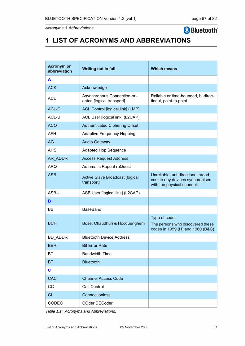
BLUETOOTH SPECIFICATION Version 1.2 [vol 1] page 57 of 82
Acronyms & Abbreviations
1 LIST OF ACRONYMS AND ABBREVIATIONS
Acronym or abbreviation Writing out in full Which means
A
ACK Acknowledge
ACL Asynchronous Connection-ori-ented [logical transport]
Reliable or time-bounded, bi-direc-tional, point-to-point.
ACL-C ACL Control [logical link] (LMP)
ACL-U ACL User [logical link] (L2CAP)
ACO Authenticated Ciphering Offset
AFH Adaptive Frequency Hopping
AG Audio Gateway
AHS Adapted Hop Sequence
AR_ADDR Access Request Address
ARQ Automatic Repeat reQuest
ASB Active Slave Broadcast [logical transport]
Unreliable, uni-directional broad-cast to any devices synchronised with the physical channel.
ASB-U ASB User [logical link] (L2CAP)
B
BB BaseBand
BCH Bose, Chaudhuri & HocquenghemType of codeThe persons who discovered these codes in 1959 (H) and 1960 (B&C)
BD_ADDR Bluetooth Device Address
BER Bit Error Rate
BT Bandwidth Time
BT Bluetooth
C
CAC Channel Access Code
CC Call Control
CL Connectionless
CODEC COder DECoder
Table 1.1: Acronyms and Abbreviations.
List of Acronyms and Abbreviations 05 November 2003 57

BLUETOOTH SPECIFICATION Version 1.2 [vol 1] page 58 of 82
Acronyms & Abbreviations
COF Ciphering Offset
CRC Cyclic Redundancy Check
CVSD Continuous Variable Slope Delta Modulation
D
DAC Device Access Code
DCE Data Communication Equipment
DCE Data Circuit-Terminating Equip-ment
In serial communications, DCE refers to a device between the communication endpoints whose sole task is to facilitate the commu-nications process; typically a modem
DCI Default Check Initialization
DH Data-High Rate Data packet type for high rate data
DIAC Dedicated Inquiry Access Code
DM Data - Medium Rate Data packet type for medium rate data
DTE Data Terminal Equipment
In serial communications, DTE refers to a device at the endpoint of the communications path; typically a computer or terminal.
DTMF Dual Tone Multiple Frequency
DUT Device Under Test
DV Data Voice Data packet type for data and voice
E
eSCO Extended Synchronous Connec-tion Oriented [logical transport]
Bi-directional, symmetric or asym-metric, point-to-point, general reg-ular data, limited retransmission.
eSCO-S Stream eSCO (unframed)used to support isochronous data delivered in a stream without fram-ing
ETSI European Telecommunications Standards Institute
Acronym or abbreviation Writing out in full Which means
Table 1.1: Acronyms and Abbreviations.
58 05 November 2003 List of Acronyms and Abbreviations

BLUETOOTH SPECIFICATION Version 1.2 [vol 1] page 59 of 82
Acronyms & Abbreviations
F
FCC Federal Communications Commission
FEC Forward Error Correction code
FH Frequency Hopping
FHS Frequency Hop Synchronization
FIFO First In First Out
FSK Frequency Shift Keying type of modulation
FW Firmware
G
GFSK Gaussian Frequency Shift Keying
GIAC General Inquiry Access Code
GM Group Management
H
HCI Host Controller Interface
HEC Header-Error-Check
HID Human Interface Device
HV High quality Voice e.g. HV1 packet
HW Hardware
I
IAC Inquiry Access Code
IEEE Institute of Electronic and Electrical Engineering
IETF Internet Engineering Task Force
IP Internet Protocol
IrDA Infra-red Data Association
IrMC Ir Mobile Communications
ISDN Integrated Services Digital Net-works
ISM Industrial, Scientific, Medical
IUT Implementation Under Test
Acronym or abbreviation Writing out in full Which means
Table 1.1: Acronyms and Abbreviations.
List of Acronyms and Abbreviations 05 November 2003 59

BLUETOOTH SPECIFICATION Version 1.2 [vol 1] page 60 of 82
Acronyms & Abbreviations
L
L2CAP Logical Link Control and Adaptation Protocol
LAP Lower Address Part
LC Link Controller Link Controller (or baseband) part of the Bluetooth protocol stack. Low level Baseband protocol handler
LC Link Control [logical link]
The control logical links LC and ACL-C are used at the link control level and link manager level, respectively.
LCP Link Control Protocol
LCSS Link Controller Service Signalling
LFSR Linear Feedback Shift Register
LLID Logical Link Identifier
LM Link Manager
LMP Link Manager Protocol For LM peer to peer communica-tion
LSB Least Significant Bit
LT_ADDR Logical Transport ADDRess
M
M Master or Mandatory
MAC Medium Access Control
MAPI Messaging Application Procedure Interface
MMI Man Machine Interface
MS Mobile Station
MS Multiplexing sublayer
MSB Most Significant Bit
MSC Message Sequence Chart
MTU Maximum Transmission Unit
N
NAK Negative Acknowledge
Acronym or abbreviation Writing out in full Which means
Table 1.1: Acronyms and Abbreviations.
60 05 November 2003 List of Acronyms and Abbreviations
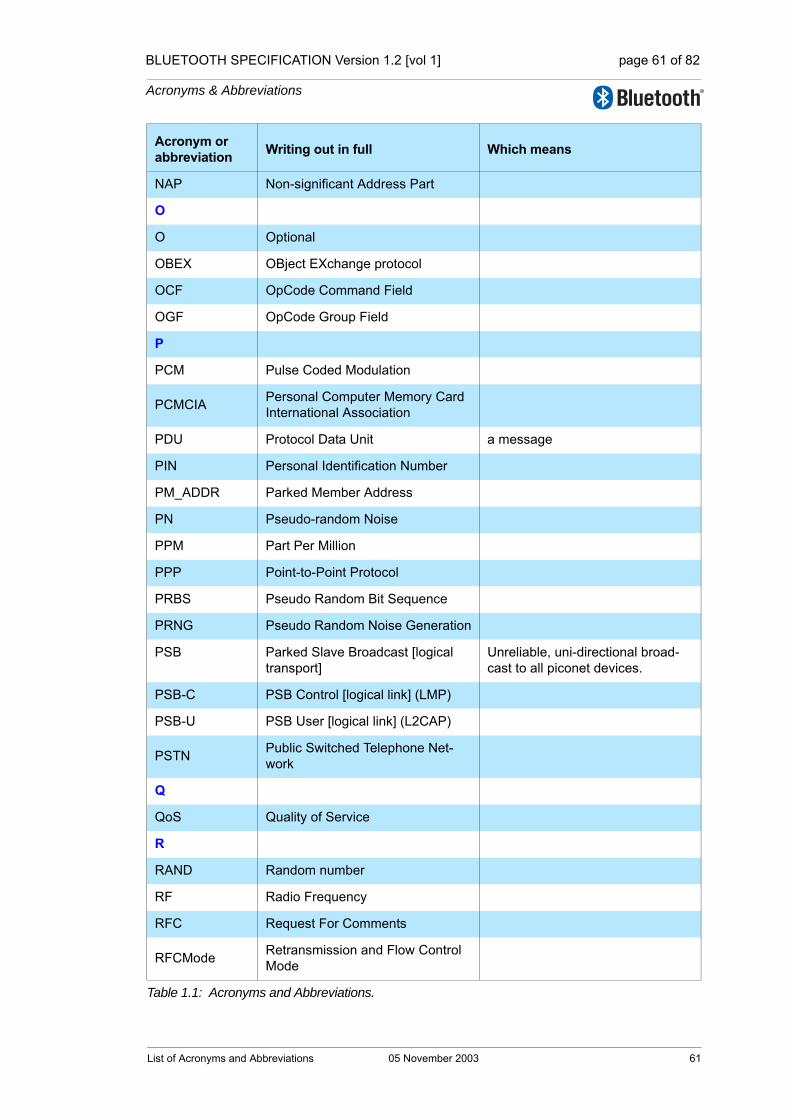
BLUETOOTH SPECIFICATION Version 1.2 [vol 1] page 61 of 82
Acronyms & Abbreviations
NAP Non-significant Address Part
O
O Optional
OBEX OBject EXchange protocol
OCF OpCode Command Field
OGF OpCode Group Field
P
PCM Pulse Coded Modulation
PCMCIA Personal Computer Memory Card International Association
PDU Protocol Data Unit a message
PIN Personal Identification Number
PM_ADDR Parked Member Address
PN Pseudo-random Noise
PPM Part Per Million
PPP Point-to-Point Protocol
PRBS Pseudo Random Bit Sequence
PRNG Pseudo Random Noise Generation
PSB Parked Slave Broadcast [logical transport]
Unreliable, uni-directional broad-cast to all piconet devices.
PSB-C PSB Control [logical link] (LMP)
PSB-U PSB User [logical link] (L2CAP)
PSTN Public Switched Telephone Net-work
Q
QoS Quality of Service
R
RAND Random number
RF Radio Frequency
RFC Request For Comments
RFCMode Retransmission and Flow Control Mode
Acronym or abbreviation Writing out in full Which means
Table 1.1: Acronyms and Abbreviations.
List of Acronyms and Abbreviations 05 November 2003 61
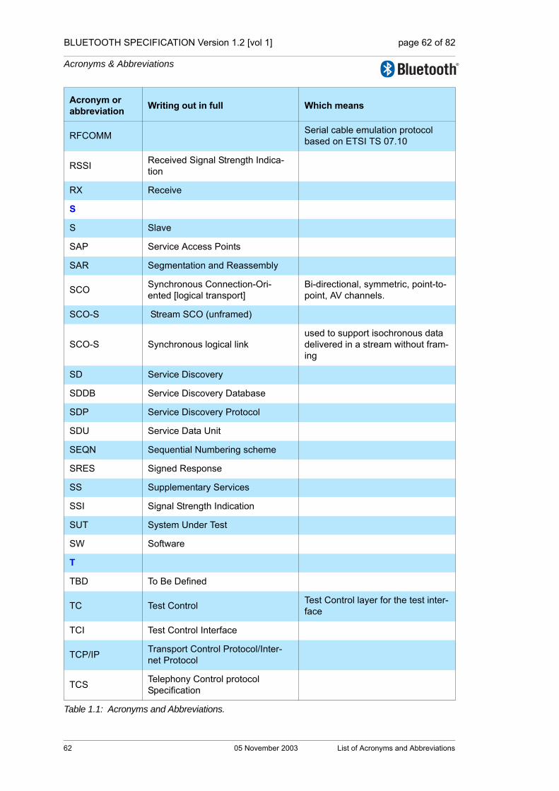
BLUETOOTH SPECIFICATION Version 1.2 [vol 1] page 62 of 82
Acronyms & Abbreviations
RFCOMM Serial cable emulation protocol based on ETSI TS 07.10
RSSI Received Signal Strength Indica-tion
RX Receive
S
S Slave
SAP Service Access Points
SAR Segmentation and Reassembly
SCO Synchronous Connection-Ori-ented [logical transport]
Bi-directional, symmetric, point-to-point, AV channels.
SCO-S Stream SCO (unframed)
SCO-S Synchronous logical linkused to support isochronous data delivered in a stream without fram-ing
SD Service Discovery
SDDB Service Discovery Database
SDP Service Discovery Protocol
SDU Service Data Unit
SEQN Sequential Numbering scheme
SRES Signed Response
SS Supplementary Services
SSI Signal Strength Indication
SUT System Under Test
SW Software
T
TBD To Be Defined
TC Test Control Test Control layer for the test inter-face
TCI Test Control Interface
TCP/IP Transport Control Protocol/Inter-net Protocol
TCS Telephony Control protocol Specification
Acronym or abbreviation Writing out in full Which means
Table 1.1: Acronyms and Abbreviations.
62 05 November 2003 List of Acronyms and Abbreviations
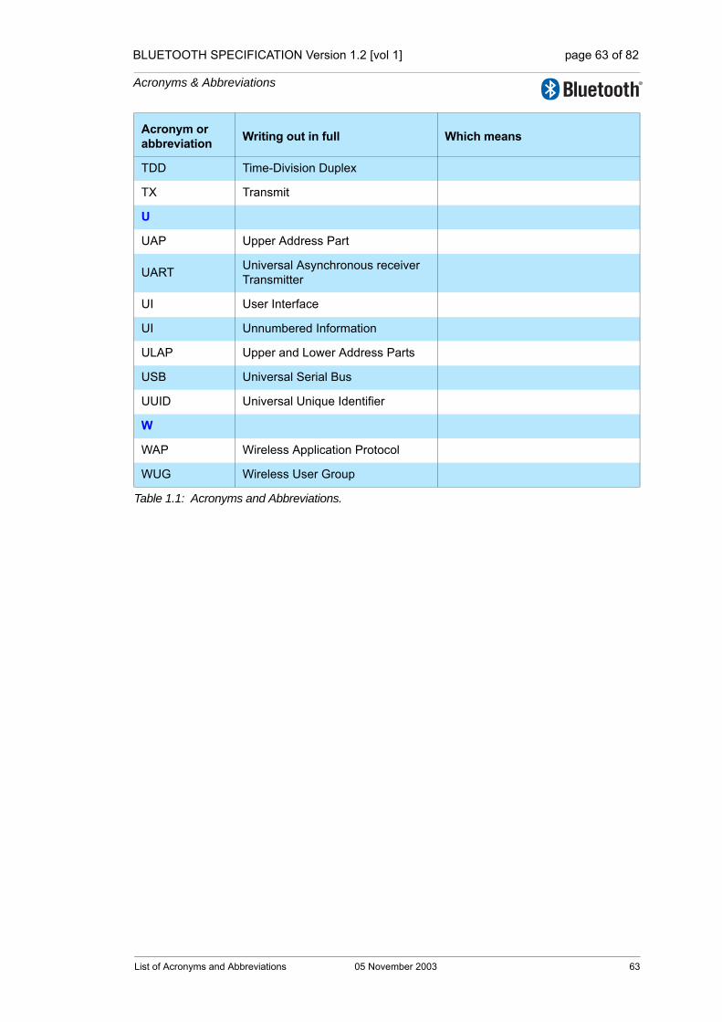
BLUETOOTH SPECIFICATION Version 1.2 [vol 1] page 63 of 82
Acronyms & Abbreviations
TDD Time-Division Duplex
TX Transmit
U
UAP Upper Address Part
UART Universal Asynchronous receiver Transmitter
UI User Interface
UI Unnumbered Information
ULAP Upper and Lower Address Parts
USB Universal Serial Bus
UUID Universal Unique Identifier
W
WAP Wireless Application Protocol
WUG Wireless User Group
Acronym or abbreviation Writing out in full Which means
Table 1.1: Acronyms and Abbreviations.
List of Acronyms and Abbreviations 05 November 2003 63

BLUETOOTH SPECIFICATION Version 1.2 [vol 1] page 64 of 82
Acronyms & Abbreviations
64 05 November 2003 List of Acronyms and Abbreviations

BLUETOOTH SPECIFICATION Version 1.2 [vol 1] page 65 of 82
Acronyms & Abbreviations
2 ABBREVIATIONS OF THE SPECIFICATION NAMES
Acronym or abbreviation Writing out in full Placement in
Specification
A2DP Advanced Audio Distribution Profile Specification vol 10 part C
AVCTP A/V Control Transport Protocol Specification vol 10 part F
AVDTP A/V Distribution Transport Profile Specification vol 10 part A
AVRCP A/V Remote Control Profile Specification vol 10 part G
BB Baseband Specification vol 2 part B
BIP Basic Imaging Profile vol 8 part E
BNEP Bluetooth Network Encapsulation Protocol Specification vol 6 part A
BPP Basic Printing Profile Specification vol 8 part F
CIP Common ISDN Access Profile Specification vol 12 part A
CTP Cordless Telephony Profile Specification vol 9 part B
DUN Dial-Up Networking Profile Specification vol 7 part C
ESDP / UPNP Extended Service Discovery Profile vol 6 part D
FAX Fax Profile Specification vol 7 part D
FTP File Transfer Profile Specification vol 8 part C
GAP Generic Access Profile Specification vol 3 part C
GAVDP Generic A/V Distribution Profile Specification vol 10 part B
GOEP Generic Object Exchange Profile Specification vol 8 part A
HCI (1) Host Controller Interface Functional Specification vol 2 part E
HCI (2) Host Controller Interface Transport Layers Specification vol 4 part A-C
HCRP Hardcopy Cable Replacement Profile Specification vol 11 part B
HFP Hands-Free Profile Specification vol 7 part E
HID Human Interface Device Profile Specification vol 11 part A
HSP Headset Profile Specification vol 7 part F
ICP Intercom Profile Specification vol 9 part C
L2CAP Logical Link Control and Adaptation Protocol Specification vol 3 part A
LAP LAN Access Profile Specification deprecated
Table 2.1: Abbreviations of the specification names.
Abbreviations of the Specification Names 05 November 2003 65
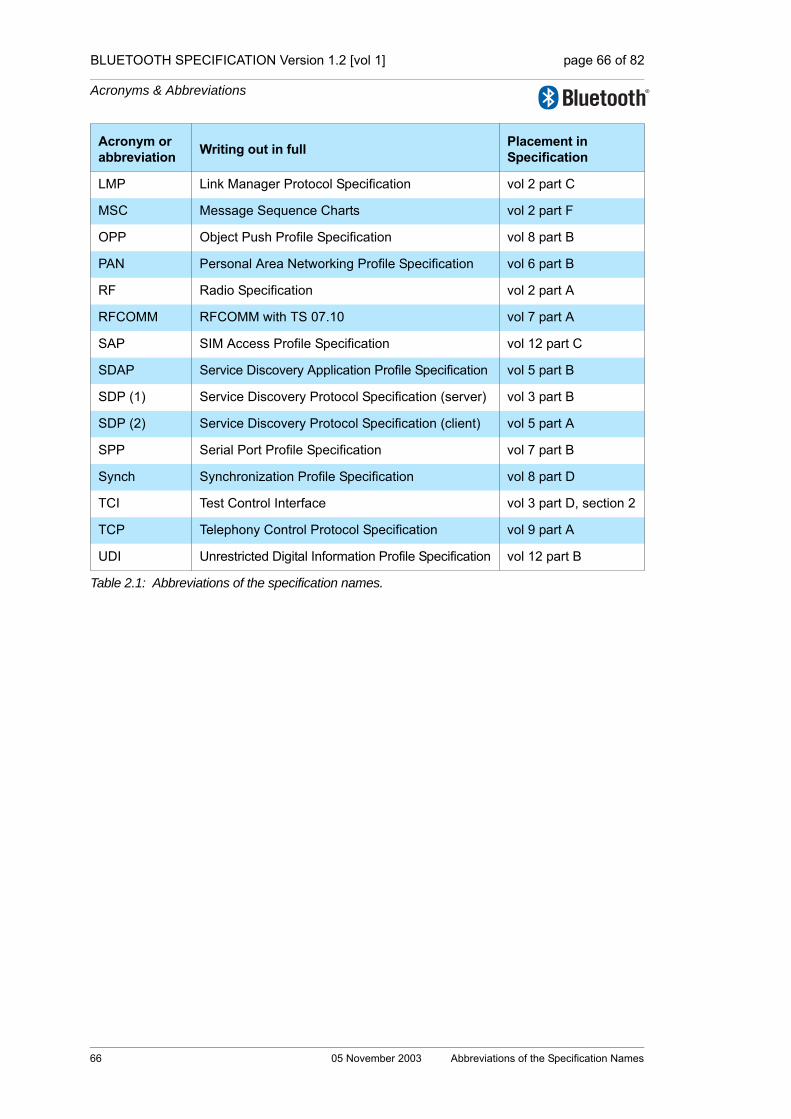
BLUETOOTH SPECIFICATION Version 1.2 [vol 1] page 66 of 82
Acronyms & Abbreviations
LMP Link Manager Protocol Specification vol 2 part C
MSC Message Sequence Charts vol 2 part F
OPP Object Push Profile Specification vol 8 part B
PAN Personal Area Networking Profile Specification vol 6 part B
RF Radio Specification vol 2 part A
RFCOMM RFCOMM with TS 07.10 vol 7 part A
SAP SIM Access Profile Specification vol 12 part C
SDAP Service Discovery Application Profile Specification vol 5 part B
SDP (1) Service Discovery Protocol Specification (server) vol 3 part B
SDP (2) Service Discovery Protocol Specification (client) vol 5 part A
SPP Serial Port Profile Specification vol 7 part B
Synch Synchronization Profile Specification vol 8 part D
TCI Test Control Interface vol 3 part D, section 2
TCP Telephony Control Protocol Specification vol 9 part A
UDI Unrestricted Digital Information Profile Specification vol 12 part B
Acronym or abbreviation Writing out in full Placement in
Specification
Table 2.1: Abbreviations of the specification names.
66 05 November 2003 Abbreviations of the Specification Names

Architecture & Terminology Overview
Part CChanges from Bluetooth Specification v 1.1
1.2

68 05 November 2003
BLUETOOTH SPECIFICATION Version 1.2 [vol 1] page 68 of 82
Changes from Bluetooth Specification v 1.1

BLUETOOTH SPECIFICATION Version 1.2 [vol 1] page 69 of 82
Changes from Bluetooth Specification v 1.1
CONTENTS
Contents ........................................................................................................691 New Features......................................................................................712 Changes in Wording ..........................................................................73
2.1 IEEE Language Update .............................................................732.1.1 Shall ..............................................................................742.1.2 Must...............................................................................742.1.3 Will.................................................................................742.1.4 Should ...........................................................................742.1.5 May................................................................................752.1.6 Can................................................................................75
2.2 Nomenclature Changes .............................................................75
3 Structure Changes .............................................................................774 Deprecated Specifications ................................................................79
4.1 Deprecated Features .................................................................794.2 Deprecated Profiles....................................................................79
05 November 2003 69

BLUETOOTH SPECIFICATION Version 1.2 [vol 1] page 70 of 82
Changes from Bluetooth Specification v 1.1
70 05 November 2003
BLUETOOTH SPECIFICATION Version 1.2 [vol 1] page 71 of 82
Changes from Bluetooth Specification v 1.1
1 NEW FEATURES
Several new features are introduced in the Bluetooth Core Specification 1.2. The major areas of improvement are:
• Architectual overview
• Faster connection
• Adaptive frequency hopping
• Extended SCO links
• Enhanced error detection and flow control
• Enhanced synchronization capability
• Enhanced flow specification
The feature descriptions are incorporated into the existing text in different core parts, described in vol2 and vol3.
New Features 05 November 2003 71

BLUETOOTH SPECIFICATION Version 1.2 [vol 1] page 72 of 82
Changes from Bluetooth Specification v 1.1
72 05 November 2003 New Features
BLUETOOTH SPECIFICATION Version 1.2 [vol 1] page 73 of 82
Changes from Bluetooth Specification v 1.1
2 CHANGES IN WORDING
Two general classes of changes to the wording of the Bluetooth Specification have been done for version 1.2. They are a formalization of the language by using conventions established by the Institute of Electrical and Electronic Engi-neers (IEEE), and a regularization of Bluetooth wireless technology-specific terms.
2.1 IEEE LANGUAGE UPDATE
The purpose of changing terms used to decribe attributes of the Specification is to make it easy for the reader to identify text that decribes requirements as opposed to background information. The general term for text that describes attributes that are required for proper implementation of Bluetooth wireless technology is Nomative. The general term for language that provides back-ground and context for normative text is "informative". These terms have been added to various sections to clarify implementation requirements.
Many portions of the Bluetooth Specification use imprecise or inaccurate terms to describe attributes of the protocol. This subsection describes the correct usage of key terms that indicate degree of requirements for processes and data structures. The information here was derived from the IEEE Style Guide, see http://standards.ieee.org/guides/style/.
The following list is a summary of the terms to be discussed in more detail below:
For clarity of the definition of those terms, the following sections document why and how they are used. For these sections only, the IEEE terms are italicized to indicate their use as a noun. Uses and examples of the use of the terms in this section are underlined.
shall is required to – used to define requirements
must is a natural consequence of -- used only to describe unavoidable situations
will it is true that -- only used in statements of fact
should is recommended that – used to indicate that among several possi-bilities one is recommended as particularly suitable, but not required
may is permitted to – used to allow options
can is able to – used to relate statements in a causal fashion
is is defined as – used to further explain elements that are previ-ously required or allowed
note <informational text ONLY>
Changes in Wording 05 November 2003 73

BLUETOOTH SPECIFICATION Version 1.2 [vol 1] page 74 of 82
Changes from Bluetooth Specification v 1.1
2.1.1 Shall
The word shall is used to indicate mandatory requirements strictly that shall be followed in order to conform to the specification and from which no deviation is permitted.
There is a strong implication that the presence of the word shall indicates a testable requirement. All testable requirements shall be reflected in the Proto-col Implementation Conformance Statement (PICS). In turn, all PICS indica-tors should be reflected in the Test Cases (TCs) either directly or indirectly.
A direct reference is a specific test for the attribute cited in the text. For exam-ple, a minimum value for a given parameter may be an entry in the TCs. Indi-rect test coverage may be appropriate if the existence of the attribute is requisite for passing a higher level test.
2.1.2 Must
The word must shall not be used when stating mandatory requirements. Must is used only to describe unavoidable situations and is seldom appropriate for the text of a Specification.
An example of an appropriate use of the term must is: “the Bluetooth radios must be in range of each other to communicate”.
2.1.3 Will
The use of the word will shall not be used when stating mandatory require-ments. The term will is only used in statements of fact. As with the term must, will is not generally applicable to the description of a protocol. An example of appropriate use of will is: “when power is removed from the radio, it can be assumed that communications will fail”
2.1.4 Should
Should equals is recommended that. The word should is used to indicate that among several possibilities one is recommended as particularly suitable with-out mentioning or excluding others. Alternatively it may indicate that a certain course of action is preferred but not necessarily required. Finally, in the nega-tive form, it indicates a certain course of action is deprecated but not prohib-ited.
In the Bluetooth Specification the term designates an optional attribute that may require an entry in the PICS.
Explicit specification of alternatives should be done when using should.
74 05 November 2003 Changes in Wording
BLUETOOTH SPECIFICATION Version 1.2 [vol 1] page 75 of 82
Changes from Bluetooth Specification v 1.1
2.1.5 May
The word may is used to indicate a course of action permissible within the lim-its of the specification. The term may equals is permitted. This is generally used when there is a single, optional attribute described, but multiple alterna-tives may be cited.
The use of may implies an optional condition in the PICS and therefore may need to be reflected in the corresponding test cases.
2.1.6 Can
The word can is used for statements of possibility and capability, whether mate-rial, physical, or causal. The term can equals is able to.
The term can shall be used only in informative text. It describes capabilities by virtue of the rules established by normative text.
2.2 NOMENCLATURE CHANGES
The nomenclature in Bluetooth 1.2 has also been updated due to new con-cepts that are introduced together with the new features and the new architec-ture (see [Part A] Section 1.2 on page 15).
Changes in Wording 05 November 2003 75

BLUETOOTH SPECIFICATION Version 1.2 [vol 1] page 76 of 82
Changes from Bluetooth Specification v 1.1
76 05 November 2003 Changes in Wording

BLUETOOTH SPECIFICATION Version 1.2 [vol 1] page 77 of 82
Changes from Bluetooth Specification v 1.1
3 STRUCTURE CHANGES
The Bluetooth Core Specification 1.2 has been significantly restructured for better consistency and readability. The most important structure changes have been performed in Baseband, LMP, HCI and L2CAP. The text in these sections has been rearranged to provide:
• Presentation of the information in a more logical progression
• Removal of redundant text and requirements
• Consolidation of baseband related requirements (for example, the Base-band Timers and Bluetooth Audio sections into the Baseband Specification)
• Alignment of the specification with the new architecture and terminology pre-sented in the Architecture Overview (see Part A on page 9)
In addition, new text and requirements have been added for the new features as well as many changes throughout the specification to update the text to use IEEE language (see Section 2 on page 73).
Structure Changes 05 November 2003 77

BLUETOOTH SPECIFICATION Version 1.2 [vol 1] page 78 of 82
Changes from Bluetooth Specification v 1.1
78 05 November 2003 Structure Changes

BLUETOOTH SPECIFICATION Version 1.2 [vol 1] page 79 of 82
Changes from Bluetooth Specification v 1.1
4 DEPRECATED SPECIFICATIONS
As the Bluetooth Specification continues to evolve, some features, protocols, and profiles are replaced with new ways of performing the same function. Often these changes reflect the evolution of the communications industry. Some of the changes merely reflect an evolved understanding of the Bluetooth environment itself.
Those functions no longer recommended are being deprecated. The term dep-recation does not mean that they are no longer allowed, but that they are no longer recommended as the best way of performing a given function.
Specifications that have been deprecated will not be included in the updated Bluetooth Specifications, but the earlier versions are still available and may be used according to the rules set forth in the Qualification Policy (PRD).
4.1 DEPRECATED FEATURES
Features deprecated in version 1.2 are:
• The use of Unit Keys for security
• Optional Paging schemes
• 23 channel hopping sequence
4.2 DEPRECATED PROFILES
For the release of Bluetooth Specification 1.2, the deprecated profiles are:
• LAN Access Profile (LAP)
• Portions of WAP over LAP
• ESDP over L2CAP and LAP
Deprecated Specifications 05 November 2003 79

BLUETOOTH SPECIFICATION Version 1.2 [vol 1] page 80 of 82
Changes from Bluetooth Specification v 1.1
80 05 November 2003 Deprecated Specifications


82

1.2
Specificationof the Bluetooth System
Wireless connections made easy
Core SystemPackage[Controller volume]
Version 1.2 05 November 2003
Specification Volume 2
BLUETOOTH SPECIFICATION Version 1.2 [vol 2] page 2 of 790
Revision History
The Revision History is shown in the “Appendix” on page 53[vol. 0].
Contributors
The persons who contributed to this specification are listed in the “Appendix” on page 53[vol. 0].
Web Site
This specification can also be found on the official Bluetooth website: http://www.bluetooth.com
Disclaimer and Copyright Notice
The copyright in these specifications is owned by the Promoter Members of Bluetooth SIG, Inc. (“Bluetooth SIG”). Use of these specifications and any related intellectual property (collectively, the “Specification”), is governed by the Promoters Membership Agreement among the Promoter Members and Blue-tooth SIG (the “Promoters Agreement”), certain membership agreements between Bluetooth SIG and its Adopter and Associate Members (the “Member-ship Agreements”) and the Bluetooth Specification Early Adopters Agreements (“1.2 Early Adopters Agreements”) among Early Adopter members of the unin-corporated Bluetooth special interest group and the Promoter Members (the “Early Adopters Agreement”). Certain rights and obligations of the Promoter Members under the Early Adopters Agreements have been assigned to Blue-tooth SIG by the Promoter Members.
Use of the Specification by anyone who is not a member of Bluetooth SIG or a party to an Early Adopters Agreement (each such person or party, a “Mem-ber”), is prohibited. The legal rights and obligations of each Member are gov-erned by their applicable Membership Agreement, Early Adopters Agreement or Promoters Agreement. No license, express or implied, by estoppel or other-wise, to any intellectual property rights are granted herein.
Any use of the Specification not in compliance with the terms of the applicable Membership Agreement, Early Adopters Agreement or Promoters Agreement is prohibited and any such prohibited use may result in termination of the appli-cable Membership Agreement or Early Adopters Agreement and other liability permitted by the applicable agreement or by applicable law to Bluetooth SIG or any of its members for patent, copyright and/or trademark infringement.
2 05 November 2003
BLUETOOTH SPECIFICATION Version 1.2 [vol 2] page 3 of 790
THE SPECIFICATION IS PROVIDED “AS IS” WITH NO WARRANTIES WHATSOEVER, INCLUDING ANY WARRANTY OF MERCHANTABILITY, NONINFRINGEMENT, FITNESS FOR ANY PARTICULAR PURPOSE, SATIS-FACTORY QUALITY, OR REASONABLE SKILL OR CARE, OR ANY WAR-RANTY ARISING OUT OF ANY COURSE OF DEALING, USAGE, TRADE PRACTICE, PROPOSAL, SPECIFICATION OR SAMPLE.
Each Member hereby acknowledges that products equipped with the Blue-tooth® technology (“Bluetooth® Products”) may be subject to various regula-tory controls under the laws and regulations of various governments worldwide. Such laws and regulatory controls may govern, among other things, the combi-nation, operation, use, implementation and distribution of Bluetooth® Prod-ucts. Examples of such laws and regulatory controls include, but are not limited to, airline regulatory controls, telecommunications regulations, technology transfer controls and health and safety regulations. Each Member is solely responsible for the compliance by their Bluetooth® Products with any such laws and regulations and for obtaining any and all required authorizations, per-mits, or licenses for their Bluetooth® Products related to such regulations within the applicable jurisdictions. Each Member acknowledges that nothing in the Specification provides any information or assistance in connection with securing such compliance, authorizations or licenses. NOTHING IN THE SPECIFICATION CREATES ANY WARRANTIES, EITHER EXPRESS OR IMPLIED, REGARDING SUCH LAWS OR REGULATIONS.
ALL LIABILITY, INCLUDING LIABILITY FOR INFRINGEMENT OF ANY INTELLECTUAL PROPERTY RIGHTS OR FOR NONCOMPLIANCE WITH LAWS, RELATING TO USE OF THE SPECIFICATION IS EXPRESSLY DIS-CLAIMED. BY USE OF THE SPECIFICATION, EACH MEMBER EXPRESSLY WAIVES ANY CLAIM AGAINST BLUETOOTH SIG AND ITS PROMOTER MEMBERS RELATED TO USE OF THE SPECIFICATION.
Bluetooth SIG reserves the right to adopt any changes or alterations to the Specification as it deems necessary or appropriate and to adopt a process for adding new Bluetooth® profiles after the release of the Specification.
Copyright © 1999, 2000, 2001, 2002, 2003
Agere Systems, Inc.,Ericsson Technology Licensing, AB,IBM Corporation,Intel Corporation,Microsoft Corporation,Motorola, Inc.,Nokia Corporation,Toshiba Corporation
*Third-party brands and names are the property of their respective owners.
05 November 2003 3

BLUETOOTH SPECIFICATION Version 1.2 [vol 2] page 4 of 790
4 05 November 2003

BLUETOOTH SPECIFICATION Version 1.2 [vol 2] page 5 of 790
TABLE OF CONTENTS
Part ARADIO SPECIFICATION
Contents ........................................................................................................271 Scope ..................................................................................................292 Frequency Bands and Channel Arrangement .................................313 Transmitter Characteristics...............................................................33
3.1 Modulation Characteristics.........................................................343.2 Spurious Emissions....................................................................35
3.2.1 In-band spurious emission ............................................353.3 Radio Frequency Tolerance .......................................................36
4 Receiver Characteristics ...................................................................374.1 Actual Sensitivity Level ..............................................................374.2 Interference Performance ..........................................................374.3 Out-of-Band Blocking.................................................................384.4 Intermodulation Characteristics..................................................384.5 Maximum Usable Level..............................................................394.6 Receiver Signal Strength Indicator.............................................394.7 Reference Signal Definition........................................................39
5 Appendix A .........................................................................................416 Appendix B .........................................................................................43
05 November 2003 5

BLUETOOTH SPECIFICATION Version 1.2 [vol 2] page 6 of 790
Part BBASEBAND SPECIFICATION
Contents ........................................................................................................471 General Description...........................................................................53
1.1 Bluetooth Clock .........................................................................541.2 Bluetooth Device Addressing.....................................................55
1.2.1 Reserved addresses .....................................................551.3 Access Codes............................................................................56
2 Physical Channels .............................................................................572.1 Physical Channel Definition .......................................................582.2 Basic Piconet Physical Channel ................................................58
2.2.1 Master-slave definition ..................................................582.2.2 Hopping characteristics ................................................592.2.3 Time slots ......................................................................592.2.4 Piconet clocks ...............................................................602.2.5 Transmit/receive timing .................................................60
2.3 Adapted Piconet Physical Channel............................................632.3.1 Hopping characteristics.................................................63
2.4 Page Scan Physical Channel ....................................................642.4.1 Clock estimate for paging..............................................642.4.2 Hopping characteristics.................................................642.4.3 Paging procedure timing ...............................................652.4.4 Page response timing ...................................................66
2.5 Inquiry Scan Physical Channel ..................................................682.5.1 Clock for inquiry ............................................................682.5.2 Hopping characteristics.................................................682.5.3 Inquiry procedure timing................................................682.5.4 Inquiry response timing.................................................68
2.6 Hop Selection ............................................................................702.6.1 General selection scheme.............................................702.6.2 Selection kernel ...........................................................742.6.3 Adapted hop selection kernel .......................................772.6.4 Control word..................................................................78
3 Physical Links ...................................................................................833.1 Link Supervision ........................................................................83
6 05 November 2003
BLUETOOTH SPECIFICATION Version 1.2 [vol 2] page 7 of 790
4 Logical Transports .............................................................................854.1 General ......................................................................................854.2 Logical Transport Address (LT_ADDR)......................................854.3 Synchronous Logical Transports................................................864.4 Asynchronous Logical Transport................................................864.5 Transmit/Receive Routines ........................................................87
4.5.1 TX Routine ....................................................................874.5.2 RX routine .....................................................................904.5.3 Flow control ...................................................................91
4.6 Active Slave Broadcast Transport..............................................924.7 Parked Slave Broadcast Transport ............................................93
4.7.1 Parked member address (PM_ADDR) ..........................934.7.2 Access request address (AR_ADDR) ...........................93
5 Logical Links ......................................................................................955.1 Link Control Logical Link (LC) ....................................................955.2 ACL Control Logical Link (ACL-C) .............................................955.3 User Asynchronous/Isochronous Logical Link (ACL-U) .............95
5.3.1 Pausing the ACL-U logical link ......................................965.4 User Synchronous Data Logical Link (SCO-S) .........................965.5 User Extended Synchronous Data Logical Link (eSCO-S) .......965.6 Logical Link Priorities .................................................................96
6 Packets................................................................................................976.1 General Format ..........................................................................976.2 Bit Ordering................................................................................976.3 Access Code..............................................................................98
6.3.1 Access code types ........................................................986.3.2 Preamble .......................................................................996.3.3 Sync word......................................................................996.3.4 Trailer ..........................................................................102
6.4 Packet Header .........................................................................1036.4.1 LT_ADDR ....................................................................1036.4.2 TYPE...........................................................................1036.4.3 FLOW..........................................................................1046.4.4 ARQN..........................................................................1046.4.5 SEQN ..........................................................................1046.4.6 HEC.............................................................................104
05 November 2003 7

BLUETOOTH SPECIFICATION Version 1.2 [vol 2] page 8 of 790
6.5 Packet Types ...........................................................................1056.5.1 Common packet types ................................................1066.5.2 SCO packets ...............................................................1096.5.3 eSCO packets ............................................................. 1106.5.4 ACL packets................................................................ 111
6.6 Payload Format ....................................................................... 1126.6.1 Synchronous data field................................................ 1126.6.2 Asynchronous data field.............................................. 113
6.7 Packet Summary ..................................................................... 116
7 Bitstream Processesing .................................................................. 1177.1 Error Checking......................................................................... 118
7.1.1 HEC generation .......................................................... 1187.1.2 CRC generation .......................................................... 119
7.2 Data Whitening ........................................................................1217.3 Error Correction .......................................................................1227.4 FEC Code: Rate 1/3 ................................................................1227.5 FEC Code: Rate 2/3 ................................................................1237.6 ARQ Scheme...........................................................................124
7.6.1 Unnumbered ARQ.......................................................1247.6.2 Retransmit filtering ......................................................1277.6.3 Flushing payloads .......................................................1307.6.4 Multi-slave considerations...........................................1307.6.5 Broadcast packets.......................................................130
8 Link Controller Operation ...............................................................1338.1 Overview of States...................................................................1338.2 Standby State...........................................................................1348.3 Connection Establishment Substates ......................................134
8.3.1 Page scan substate.....................................................1348.3.2 Page substate .............................................................1368.3.3 Page response substates............................................139
8.4 Device Discovery Substates ....................................................1438.4.1 Inquiry scan substate ..................................................1448.4.2 Inquiry substate...........................................................1458.4.3 Inquiry response substate ...........................................146
8.5 Connection State .....................................................................148
8 05 November 2003
BLUETOOTH SPECIFICATION Version 1.2 [vol 2] page 9 of 790
8.6 Active Mode .............................................................................1498.6.1 Polling in the active mode ..........................................1508.6.2 SCO ............................................................................1508.6.3 eSCO ..........................................................................1518.6.4 Broadcast scheme ......................................................1548.6.5 Role switch ..................................................................1558.6.6 Scatternet ....................................................................1578.6.7 Hop sequence switching .............................................1588.6.8 Channel classificaition and channel map selection ...1618.6.9 Power Management ....................................................162
8.7 Sniff Mode ................................................................................1638.7.1 Sniff Transition Mode ..................................................164
8.8 Hold Mode................................................................................1658.9 Park State.................................................................................165
8.9.1 Beacon train ................................................................1668.9.2 Beacon access window...............................................1688.9.3 Parked slave synchronization......................................1698.9.4 Parking ........................................................................1708.9.5 Master-initiated unparking ...........................................1718.9.6 Slave-initiated unparking .............................................1718.9.7 Broadcast scan window...............................................1728.9.8 Polling in the park state ...............................................172
9 Audio .................................................................................................1739.1 LOG PCM CODEC...................................................................1739.2 CVSD CODEC .........................................................................1739.3 Error Handling..........................................................................1769.4 General Audio Requirements...................................................176
9.4.1 Signal levels ................................................................1769.4.2 CVSD audio quality .....................................................176
10 List of Figures...................................................................................17711 List of Tables ....................................................................................181
Appendix A: General Audio Recommendations ............................................................182
Appendix B: Timers ..........................................................................................................185
Appendix C: ......................................................................................................Recommendations for AFH Operation in Park, Hold and Sniff .............187
05 November 2003 9
BLUETOOTH SPECIFICATION Version 1.2 [vol 2] page 10 of 790
Part CLINK MANAGER PROTOCOL
Contents ......................................................................................................1911 Introduction ......................................................................................1952 General Rules...................................................................................197
2.1 Message Transport ..................................................................1972.2 Synchronization .......................................................................1972.3 Packet Format .........................................................................1982.4 Transactions ............................................................................199
2.4.1 LMP Response Timeout..............................................2002.5 Error Handling..........................................................................200
2.5.1 Transaction collision resolution ...................................2012.6 Procedure Rules ......................................................................2012.7 General Response Messages .................................................2022.8 Specification Writing Policies ...................................................202
3 Device Features ...............................................................................2033.1 General Description .................................................................2033.2 Feature Definitions...................................................................2033.3 Feature Mask Definition...........................................................2073.4 Link Manager Interoperability policy ........................................208
4 Procedure Rules ..............................................................................2094.1 Connection Control ..................................................................209
4.1.1 Connection establishment...........................................2094.1.2 Detach.........................................................................2104.1.3 Power control .............................................................. 2114.1.4 Adaptive frequency hopping .......................................2134.1.5 Channel classification .................................................2164.1.6 Link supervision ..........................................................2184.1.7 Channel quality driven data rate change (CQDDR) ....2194.1.8 Quality of service (QoS) ..............................................2204.1.9 Paging scheme parameters ........................................2224.1.10 Control of multi-slot packets........................................223
4.2 Security....................................................................................2244.2.1 Authentication .............................................................2244.2.2 Pairing.........................................................................2264.2.3 Change link key ..........................................................2294.2.4 Change current link key type.......................................2304.2.5 Encryption ...................................................................2324.2.6 Request supported encryption key size ......................236
10 05 November 2003
BLUETOOTH SPECIFICATION Version 1.2 [vol 2] page 11 of 790
4.3 Informational Requests ............................................................2374.3.1 Timing accuracy ..........................................................2374.3.2 Clock offset..................................................................2384.3.3 LMP version ................................................................2384.3.4 Supported features......................................................2394.3.5 Name request..............................................................241
4.4 Role Switch ..............................................................................2424.4.1 Slot offset ....................................................................2424.4.2 Role switch ..................................................................243
4.5 Modes of Operation .................................................................2454.5.1 Hold mode...................................................................2454.5.2 Park state ....................................................................2474.5.3 Sniff mode ...................................................................253
4.6 Logical Transports....................................................................2564.6.1 SCO logical transport ..................................................2564.6.2 eSCO logical transport ................................................259
4.7 Test Mode ................................................................................2644.7.1 Activation and deactivation of test mode.....................2644.7.2 Control of test mode....................................................2654.7.3 Summary of test mode PDUs......................................266
5 Summary...........................................................................................2695.1 PDU Summary ........................................................................2695.2 Parameter Definitions ..............................................................2775.3 Default Values ..........................................................................284
6 List of Figures...................................................................................2857 List of Tables ....................................................................................289
05 November 2003 11

BLUETOOTH SPECIFICATION Version 1.2 [vol 2] page 12 of 790
Part DERROR CODES
Contents ......................................................................................................2931 Overview of Error Codes.................................................................295
1.1 Usage Descriptions..................................................................2951.2 HCI Command Errors ..............................................................2951.3 List of Error Codes...................................................................296
2 Error Code Descriptions .................................................................2992.1 Unknown HCI Command (0X01) .............................................2992.2 Unknown Connection Identifier (0X02) ....................................2992.3 Hardware Failure (0X03) .........................................................2992.4 Page Timeout (0X04)...............................................................2992.5 Authentication Failure (0X05) ..................................................2992.6 PIN Missing (0X06)..................................................................2992.7 Memory Capacity Exceeded (0X07) ........................................2992.8 Connection Timeout (0X08) .....................................................3002.9 Connection Limit Exceeded (0X09) .........................................3002.10 Synchronous Connection Limit to a Device Exceeded (0X0A) 3002.11 ACL Connection Already Exists (0X0B)...................................3002.12 Command Disallowed (0X0C) .................................................3002.13 Connection Rejected due to Limited Resources (0X0D) .........3002.14 Connection Rejected due to Security Reasons (0X0E) ...........3002.15 Connection Rejected due to Unacceptable BD_ADDR (0X0F)3012.16 Connection Accept Timeout Exceeded (0X10) ........................3012.17 Unsupported Feature or Parameter Value (0X11) ...................3012.18 Invalid HCI Command Parameters (0X12) ..............................3012.19 Remote User Terminated Connection (0X13)..........................3012.20 Remote Device Terminated Connection due to Low Resources
(0X14) ......................................................................................3022.21 Remote Device Terminated Connection due to Power Off
(0X15) ......................................................................................3022.22 Connection Terminated by Local Host (0X16) .........................3022.23 Repeated Attempts (0X17) ......................................................3022.24 Pairing not Allowed (0X18) ......................................................3022.25 Unknown LMP PDU (0X19) .....................................................3022.26 Unsupported Remote Feature (0X1A) .....................................3022.27 SCO Offset Rejected (0X1B) ...................................................3022.28 SCO Interval Rejected (0X1C).................................................3032.29 SCO Air Mode Rejected (0X1D) ..............................................3032.30 INvalid LMP Parameters (0X1E)..............................................3032.31 Unspecified Error (0X1F) .........................................................3032.32 Unsupported LMP Parameter Value (0X20) ............................303
12 05 November 2003
BLUETOOTH SPECIFICATION Version 1.2 [vol 2] page 13 of 790
2.33 Role Change Not Allowed (0X21) ............................................3032.34 LMP Response Timeout (0X22)...............................................3032.35 LMP Error Transaction Collision (0X23)...................................3042.36 LMP PDU Not Allowed (0X24) .................................................3042.37 Encryption Mode Not Acceptable (0X25) .................................3042.38 Link Key Can Not be Changed (0X26).....................................3042.39 Requested Qos is Not Supported (0X27).................................3042.40 Instant Passed (0X28)..............................................................3042.41 Pairing with Unit Key Not Supported (0X29) ............................3042.42 DIFFERENT TRANSACTION COLLISION (0X2A)..................3042.43 QoS Unacceptable Parameter (0X2C).....................................3042.44 QoS Rejected (0X2D) ..............................................................3052.45 Channel Classification Not Supported (0X2E) .........................3052.46 Insufficient Security (0X2F) ......................................................3052.47 Parameter out of Mandatory Range (0X30) .............................3052.48 Role Switch Pending (0X32) ....................................................3052.49 Reserved Slot Violation (0X34) ................................................3052.50 Role Switch Failed (0X35)........................................................305
05 November 2003 13

BLUETOOTH SPECIFICATION Version 1.2 [vol 2] page 14 of 790
Part EHOST CONTROLLER INTERFACE FUNCTIONAL SPECIFICATION
Contents ......................................................................................................3091 Introduction ......................................................................................317
1.1 Lower Layers of the Bluetooth Software Stack ........................317
2 Overview of Host Controller Transport Layer ...............................3193 Overview of Commands and Events ..............................................321
3.1 Generic Events ........................................................................3223.2 Device Setup ...........................................................................3223.3 Controller Flow Control ............................................................3233.4 Controller Information ..............................................................3233.5 Controller Configuration...........................................................3243.6 Device Discovery .....................................................................3253.7 Connection Setup ....................................................................3273.8 Remote Information .................................................................3293.9 Synchronous Connections.......................................................3303.10 Connection State .....................................................................3313.11 Piconet Structure .....................................................................3323.12 Quality of Service.....................................................................3333.13 Physical Links ..........................................................................3343.14 Host Flow Control ....................................................................3353.15 Link Information .......................................................................3363.16 Authentication and Encryption .................................................3373.17 Testing .....................................................................................3393.18 Alphabetical List of Commands and Events ...........................340
4 HCI Flow Control ..............................................................................3454.1 Host to Controller Data Flow Control .......................................3454.2 Controller to Host Data Flow Control .......................................3464.3 Disconnection Behaviour .........................................................3474.4 Command Flow Control ...........................................................3474.5 Command Error Handling ........................................................348
14 05 November 2003
BLUETOOTH SPECIFICATION Version 1.2 [vol 2] page 15 of 790
5 HCI Data Formats .............................................................................3495.1 Introduction ..............................................................................3495.2 Data and Parameter Formats...................................................3495.3 Connection Handles.................................................................3505.4 Exchange of HCI-Specific Information .....................................351
5.4.1 HCI Command Packet.................................................3515.4.2 HCI ACL Data Packets................................................3535.4.3 HCI Synchronous Data Packets..................................3555.4.4 HCI Event Packet ........................................................356
6 HCI Configuration Parameters ........................................................3576.1 Scan Enable.............................................................................3576.2 Inquiry Scan Interval ................................................................3576.3 Inquiry Scan Window ...............................................................3586.4 Inquiry Scan Type ....................................................................3586.5 Inquiry Mode ............................................................................3586.6 Page Timeout...........................................................................3596.7 Connection Accept Timeout .....................................................3596.8 Page Scan Interval...................................................................3606.9 Page Scan Window..................................................................3606.10 Page Scan Period Mode ..........................................................3606.11 Page Scan Type.......................................................................3616.12 Voice Setting ............................................................................3616.13 PIN Type ..................................................................................3626.14 Link Key ...................................................................................3626.15 Authentication Enable ..............................................................3626.16 Encryption Mode ......................................................................3636.17 Failed Contact Counter ............................................................3646.18 Hold Mode Activity ...................................................................3646.19 Link Policy Settings..................................................................3656.20 Flush Timeout ..........................................................................3666.21 Num Broadcast Retransmissions.............................................3666.22 Link Supervision Timeout.........................................................3676.23 Synchronous Flow Control Enable...........................................3676.24 Local Name..............................................................................3686.25 Class Of Device .......................................................................3686.26 Supported Commands .............................................................369
05 November 2003 15
BLUETOOTH SPECIFICATION Version 1.2 [vol 2] page 16 of 790
7 HCI Commands and Events ............................................................3737.1 Link Control Commands ..........................................................373
7.1.1 Inquiry Command........................................................3737.1.2 Inquiry Cancel Command............................................3757.1.3 Periodic Inquiry Mode Command................................3767.1.4 Exit Periodic Inquiry Mode Command.........................3797.1.5 Create Connection Command.....................................3807.1.6 Disconnect Command.................................................3837.1.7 Create Connection Cancel Command ........................3847.1.8 Accept Connection Request Command......................3867.1.9 Reject Connection Request Command.......................3887.1.10 Link Key Request Reply Command ............................3897.1.11 Link Key Request Negative Reply Command.............3917.1.12 PIN Code Request Reply Command ..........................3927.1.13 PIN Code Request Negative Reply Command ...........3947.1.14 Change Connection Packet Type Command..............3957.1.15 Authentication Requested Command .........................3987.1.16 Set Connection Encryption Command........................3997.1.17 Change Connection Link Key Command....................4007.1.18 Master Link Key Command.........................................4017.1.19 Remote Name Request Command.............................4027.1.20 Remote Name Request Cancel Command.................4047.1.21 Read Remote Supported Features Command............4057.1.22 Read Remote Extended Features Command ............4067.1.23 Read Remote Version Information Command ............4077.1.24 Read Clock Offset Command .....................................4087.1.25 Read LMP Handle Command ....................................4097.1.26 Setup Synchronous Connection Command ............... 4117.1.27 Accept Synchronous Connection Request Command 4157.1.28 Reject Synchronous Connection Request Command.419
16 05 November 2003

BLUETOOTH SPECIFICATION Version 1.2 [vol 2] page 17 of 790
7.2 Link Policy Commands.............................................................4207.2.1 Hold Mode Command .................................................4207.2.2 Sniff Mode Command..................................................4227.2.3 Exit Sniff Mode Command...........................................4257.2.4 Park State Command ..................................................4267.2.5 Exit Park State Command ...........................................4287.2.6 QoS Setup Command .................................................4297.2.7 Role Discovery Command...........................................4317.2.8 Switch Role Command................................................4327.2.9 Read Link Policy Settings Command ..........................4337.2.10 Write Link Policy Settings Command ..........................4347.2.11 Read Default Link Policy Settings Command .............4367.2.12 Write Default Link Policy Settings Command .............4377.2.13 Flow Specification Command .....................................438
7.3 Controller & Baseband Commands..........................................4407.3.1 Set Event Mask Command..........................................4407.3.2 Reset Command .........................................................4427.3.3 Set Event Filter Command ..........................................4437.3.4 Flush Command..........................................................4487.3.5 Read PIN Type Command ..........................................4507.3.6 Write PIN Type Command...........................................4517.3.7 Create New Unit Key Command .................................4527.3.8 Read Stored Link Key Command................................4537.3.9 Write Stored Link Key Command ................................4547.3.10 Delete Stored Link Key Command ..............................4567.3.11 Write Local Name Command ......................................4577.3.12 Read Local Name Command......................................4587.3.13 Read Connection Accept Timeout Command .............4597.3.14 Write Connection Accept Timeout Command .............4607.3.15 Read Page Timeout Command...................................4617.3.16 Write Page Timeout Command ...................................4627.3.17 Read Scan Enable Command.....................................4637.3.18 Write Scan Enable Command .....................................4647.3.19 Read Page Scan Activity Command ...........................4657.3.20 Write Page Scan Activity Command ...........................4677.3.21 Read Inquiry Scan Activity Command.........................4687.3.22 Write Inquiry Scan Activity Command .........................4697.3.23 Read Authentication Enable Command ......................470
05 November 2003 17
BLUETOOTH SPECIFICATION Version 1.2 [vol 2] page 18 of 790
7.3.24 Write Authentication Enable Command ......................4717.3.25 Read Encryption Mode Command..............................4727.3.26 Write Encryption Mode Command ..............................4737.3.27 Read Class of Device Command................................4747.3.28 Write Class of Device Command ................................4757.3.29 Read Voice Setting Command....................................4767.3.30 Write Voice Setting Command ....................................4777.3.31 Read Automatic Flush Timeout Command .................4787.3.32 Write Automatic Flush Timeout Command..................4797.3.33 Read Num Broadcast Retransmissions Command.....4807.3.34 Write Num Broadcast Retransmissions Command.....4817.3.35 Read Hold Mode Activity Command ...........................4827.3.36 Write Hold Mode Activity Command ...........................4837.3.37 Read Transmit Power Level Command ......................4847.3.38 Read Synchronous Flow Control Enable Command...4867.3.39 Write Synchronous Flow Control Enable Command...4877.3.40 Set Controller To Host Flow Control Command ..........4887.3.41 Host Buffer Size Command.........................................4897.3.42 Host Number Of Completed Packets Command ........4917.3.43 Read Link Supervision Timeout Command.................4937.3.44 Write Link Supervision Timeout Command.................4947.3.45 Read Number Of Supported IAC Command...............4967.3.46 Read Current IAC LAP Command ..............................4977.3.47 Write Current IAC LAP Command ..............................4987.3.48 Read Page Scan Period Mode Command..................5007.3.49 Write Page Scan Period Mode Command ..................5017.3.50 Set AFH Host Channel Classification Command .......5027.3.51 Read Inquiry Scan Type Command ...........................5037.3.52 Write Inquiry Scan Type Command ...........................5047.3.53 Read Inquiry Mode Command ...................................5057.3.54 Write Inquiry Mode Command ...................................5067.3.55 Read Page Scan Type Command ..............................5077.3.56 Write Page Scan Type Command ..............................5087.3.57 Read AFH Channel Assessment Mode Command ....5097.3.58 Write AFH Channel Assessment Mode Command ....510
18 05 November 2003

BLUETOOTH SPECIFICATION Version 1.2 [vol 2] page 19 of 790
7.4 Informational Parameters.........................................................5127.4.1 Read Local Version Information Command.................5127.4.2 Read Local Supported Commands Command............5147.4.3 Read Local Supported Features Command................5157.4.4 Read Local Extended Features Command ................5167.4.5 Read Buffer Size Command........................................5187.4.6 Read BD_ADDR Command........................................520
7.5 Status Parameters....................................................................5217.5.1 Read Failed Contact Counter Command ....................5217.5.2 Reset Failed Contact Counter Command ...................5237.5.3 Read Link Quality Command ......................................5247.5.4 Read RSSI Command.................................................5257.5.5 Read AFH Channel Map Command ...........................5277.5.6 Read Clock Command ...............................................529
7.6 Testing Commands ..................................................................5317.6.1 Read Loopback Mode Command ...............................5317.6.2 Write Loopback Mode Command................................5327.6.3 Enable Device Under Test Mode Command ...............535
7.7 Events ......................................................................................5377.7.1 Inquiry Complete Event ...............................................5377.7.2 Inquiry Result Event ....................................................5387.7.3 Connection Complete Event........................................5407.7.4 Connection Request Event..........................................5417.7.5 Disconnection Complete Event ...................................5437.7.6 Authentication Complete Event ...................................5447.7.7 Remote Name Request Complete Event ....................5457.7.8 Encryption Change Event............................................5467.7.9 Change Connection Link Key Complete Event ...........5477.7.10 Master Link Key Complete Event ................................5487.7.11 Read Remote Supported Features Complete Event...5497.7.12 Read Remote Version Information Complete Event....5507.7.13 QoS Setup Complete Event ........................................5517.7.14 Command Complete Event .........................................5537.7.15 Command Status Event...............................................5547.7.16 Hardware Error Event..................................................5557.7.17 Flush Occurred Event..................................................5557.7.18 Role Change Event .....................................................5567.7.19 Number Of Completed Packets Event ........................557
05 November 2003 19
BLUETOOTH SPECIFICATION Version 1.2 [vol 2] page 20 of 790
7.7.20 Mode Change Event ...................................................5587.7.21 Return Link Keys Event...............................................5607.7.22 PIN Code Request Event ............................................5617.7.23 Link Key Request Event..............................................5627.7.24 Link Key Notification Event .........................................5637.7.25 Loopback Command Event.........................................5647.7.26 Data Buffer Overflow Event.........................................5647.7.27 Max Slots Change Event.............................................5657.7.28 Read Clock Offset Complete Event ............................5667.7.29 Connection Packet Type Changed Event ...................5677.7.30 QoS Violation Event ....................................................5697.7.31 Page Scan Repetition Mode Change Event................5707.7.32 Flow Specification Complete Event.............................5717.7.33 Inquiry Result with RSSI Event ..................................5737.7.34 Read Remote Extended Features Complete Event ....5757.7.35 Synchronous Connection Complete Event .................5767.7.36 Synchronous Connection Changed event...................578
8 List of Figures ..................................................................................5819 List of Tables ....................................................................................583
Appendix A: Deprecated Commands, Events and Configuration Parameters ...........585
20 05 November 2003

BLUETOOTH SPECIFICATION Version 1.2 [vol 2] page 21 of 790
Part FMESSAGE SEQUENCE CHARTS
Contents ......................................................................................................5951 Introduction ......................................................................................599
1.1 Notation....................................................................................5991.2 Flow of Control .........................................................................6001.3 Example MSC ..........................................................................600
2 Services Without Connection Request ..........................................6012.1 Remote Name Request............................................................6012.2 One-time Inquiry.......................................................................6022.3 Periodic Inquiry ........................................................................604
3 ACL Connection Establishment and Detachment.........................6073.1 Connection Setup ....................................................................608
4 Optional Activities After ACL Connection Establishment............6154.1 Authentication Requested........................................................6154.2 Set Connection Encryption.......................................................6164.3 Change Connection Link Key...................................................6174.4 Master Link Key .......................................................................6184.5 Read Remote Supported Features ..........................................6204.6 Read Remote Extended Features ...........................................6204.7 Read Clock Offset ....................................................................6214.8 Read Remote Version Information...........................................6214.9 QOS Setup...............................................................................6224.10 Switch Role ..............................................................................622
5 Synchronous Connection Establishment and Detachment .........6255.1 Synchronous Connection Setup...............................................625
6 Sniff, Hold and Park .........................................................................6316.1 Sniff Mode ................................................................................6316.2 Hold Mode................................................................................6326.3 Park State.................................................................................634
7 Buffer Management, Flow Control..................................................6378 Loopback Mode................................................................................639
8.1 Local Loopback Mode..............................................................6398.2 Remote Loopback Mode..........................................................641
9 List of Figures...................................................................................643
05 November 2003 21
BLUETOOTH SPECIFICATION Version 1.2 [vol 2] page 22 of 790
Part GSAMPLE DATA
Contents ......................................................................................................6471 Encryption Sample Data..................................................................649
1.1 Generating Kc' from Kc,...........................................................6491.2 First Set of Sample Data..........................................................6521.3 Second Set of Sample Data.....................................................6601.4 Third Set of Samples ...............................................................6681.5 Fourth Set of Samples .............................................................676
2 Frequency Hopping Sample Data...................................................6852.1 First set ....................................................................................6862.2 Second set...............................................................................6922.3 Third set...................................................................................698
3 Access Code Sample Data ..............................................................7054 HEC and Packet Header Sample Data............................................7095 CRC Sample Data............................................................................. 7116 Complete Sample Packets ..............................................................713
6.1 Example of DH1 Packet...........................................................7136.2 Example of DM1 Packet ..........................................................714
7 Whitening Sequence Sample Data .................................................7158 FEC Sample Data .............................................................................7199 Encryption Key Sample Data ..........................................................721
9.1 Four Tests of E1.......................................................................7219.2 Four Tests of E21.....................................................................7269.3 Three Tests of E22...................................................................7289.4 Tests of E22 With Pin Augmenting...........................................7309.5 Four Tests of E3.......................................................................740
22 05 November 2003
BLUETOOTH SPECIFICATION Version 1.2 [vol 2] page 23 of 790
Part HSECURITY SPECIFICATION
Contents ......................................................................................................7471 Security Overview ............................................................................7492 Random Number Generation ..........................................................7513 Key Management..............................................................................753
3.1 Key Types ................................................................................7533.2 Key Generation and Initialization .............................................755
3.2.1 Generation of initialization key, ...................................7563.2.2 Authentication..............................................................7563.2.3 Generation of a unit key ..............................................7563.2.4 Generation of a combination key.................................7573.2.5 Generating the encryption key ....................................7583.2.6 Point-to-multipoint configuration..................................7593.2.7 Modifying the link keys ................................................7603.2.8 Generating a master key .............................................760
4 Encryption.........................................................................................7634.1 Encryption Key Size Negotiation..............................................7644.2 Encryption of Broadcast Messages..........................................7644.3 Encryption Concept..................................................................7654.4 Encryption Algorithm................................................................766
4.4.1 The operation of the cipher .........................................7684.5 LFSR Initialization ....................................................................7694.6 Key Stream Sequence .............................................................772
5 Authentication ..................................................................................7735.1 Repeated Attempts ..................................................................775
6 The Authentication And Key-Generating Functions.....................7776.1 The Authentication Function E1...............................................7776.2 The Functions Ar and A’r..........................................................779
6.2.1 The round computations..............................................7796.2.2 The substitution boxes “e” and “l”................................7796.2.3 Key scheduling ............................................................780
6.3 E2-Key Generation Function for Authentication.......................7816.4 E3-Key Generation Function for Encryption.............................783
7 List of Figures...................................................................................7858 List of Tables ....................................................................................787
05 November 2003 23

BLUETOOTH SPECIFICATION Version 1.2 [vol 2] page 24 of 790
24 05 November 2003
Core System Package [Controller volume]
Part ARADIO SPECIFICATION

26 05 November 2003
BLUETOOTH SPECIFICATION Version 1.2 [vol 2] page 26 of 790
Radio Specification

BLUETOOTH SPECIFICATION Version 1.2 [vol 2] page 27 of 790
Radio Specification
CONTENTS
1 Scope ..................................................................................................292 Frequency Bands and Channel Arrangement .................................313 Transmitter Characteristics...............................................................33
3.1 Modulation Characteristics.........................................................343.2 Spurious Emissions....................................................................35
3.2.1 In-band spurious emission ............................................353.3 Radio Frequency Tolerance .......................................................36
4 Receiver Characteristics ...................................................................374.1 Actual Sensitivity Level ..............................................................374.2 Interference Performance ..........................................................374.3 Out-of-Band Blocking.................................................................384.4 Intermodulation Characteristics..................................................384.5 Maximum Usable Level..............................................................394.6 Receiver Signal Strength Indicator.............................................394.7 Reference Signal Definition........................................................39
5 Appendix A .........................................................................................416 Appendix B .........................................................................................43
05 November 2003 27

BLUETOOTH SPECIFICATION Version 1.2 [vol 2] page 28 of 790
Radio Specification
28 05 November 2003

BLUETOOTH SPECIFICATION Version 1.2 [vol 2] page 29 of 790
Radio Specification
1 SCOPE
Bluetooth devices operate in the unlicensed 2.4 GHz ISM (Industrial Scientific Medical) band. A frequency hop transceiver is applied to combat interference and fading. A shaped, binary FM modulation is applied to minimize transceiver complexity. The symbol rate is 1 Ms/s. For full duplex transmission, a Time-Division Duplex (TDD) scheme is used. This specification defines the require-ments for a Bluetooth radio.
Requirements are defined for two reasons:
• Provide compatibility between radios used in the system
• Define the quality of the system
The Bluetooth radio shall fulfil the stated requirements under the operating condi-tions specified in Appendix A and Appendix B. The radio parameters shall be measured according to the methods described in the RF Test Specification.
This specification is based on the established regulations for Europe, Japan and North America. The standard documents listed below are only for informa-tion, and are subject to change or revision at any time.
Europe:
Approval Standards: European Telecommunications Standards Institute, ETSIDocuments: EN 300 328, ETS 300-826Approval Authority: National Type Approval Authorities
Japan:
Approval Standards: Association of Radio Industries and Businesses, ARIBDocuments: ARIB STD-T66Approval Authority: Ministry of Post and Telecommunications, MPT.
North America:
Approval Standards: Federal Communications Commission, FCC, USADocuments: CFR47, Part 15, Sections 15.205, 15.209, 15.247 and 15.249
Approval Standards: Industry Canada, IC, CanadaDocuments: GL36
Approval Authority: FCC (USA), Industry Canada (Canada)
Scope 05 November 2003 29

BLUETOOTH SPECIFICATION Version 1.2 [vol 2] page 30 of 790
Radio Specification
30 05 November 2003 Scope
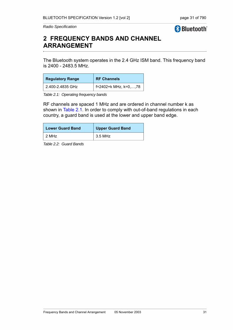
BLUETOOTH SPECIFICATION Version 1.2 [vol 2] page 31 of 790
Radio Specification
2 FREQUENCY BANDS AND CHANNEL ARRANGEMENT
The Bluetooth system operates in the 2.4 GHz ISM band. This frequency band is 2400 - 2483.5 MHz.
RF channels are spaced 1 MHz and are ordered in channel number k as shown in Table 2.1. In order to comply with out-of-band regulations in each country, a guard band is used at the lower and upper band edge.
Regulatory Range RF Channels
2.400-2.4835 GHz f=2402+k MHz, k=0,…,78
Table 2.1: Operating frequency bands
Lower Guard Band Upper Guard Band
2 MHz 3.5 MHz
Table 2.2: Guard Bands
Frequency Bands and Channel Arrangement 05 November 2003 31

BLUETOOTH SPECIFICATION Version 1.2 [vol 2] page 32 of 790
Radio Specification
32 05 November 2003 Frequency Bands and Channel Arrangement

BLUETOOTH SPECIFICATION Version 1.2 [vol 2] page 33 of 790
Radio Specification
3 TRANSMITTER CHARACTERISTICS
The requirements stated in this section are given as power levels at the antenna connector of the Bluetooth device. If the device does not have a con-nector, a reference antenna with 0 dBi gain is assumed.
Due to difficulty in measurement accuracy in radiated measurements, systems with an integral antenna should provide a temporary antenna connector during type approval.
If transmitting antennas of directional gain greater than 0 dBi are used, the applicable paragraphs in EN 300 328, EN 301 489-17and FCC part 15 shall be compensated for.
The device is classified into three power classes.
Power class 1 device shall implement power control. The power control is used for limiting the transmitted power over +4 dBm. Power control capability under +4 dBm is optional and could be used for optimizing the power consumption and overall interference level. The power steps shall form a monotonic sequence, with a maximum step size of 8 dB and a minimum step size of 2 dB. A class 1 device with a maximum transmit power of +20 dBm shall be able to control its transmit power down to 4 dBm or less.
Devices with power control capability optimizes the output power in a physical link with LMP commands (see Link Manager Protocol). It is done by measuring RSSI and reporting back if the transmission power shall be increased or decreased if possible.
In a connection, the output power shall not exceed the maximum output power of power class 2 for transmitting packets if the receiving device does not sup-port the necessary messaging for sending the power control messages, see
Power Class
Maximum OutputPower (Pmax)
Nominal Output Power
MinimumOutput Power1
1. Minimum output power at maximum power setting.
Power Control
1 100 mW (20 dBm) N/A 1 mW (0 dBm)Pmin<+4 dBm to PmaxOptional:Pmin2 to Pmax
2. The lower power limit Pmin<-30dBm is suggested but is not mandatory, and may be chosen according to application needs.
2 2.5 mW (4 dBm) 1 mW (0 dBm) 0.25 mW (-6 dBm)Optional: Pmin2) to Pmax
3 1 mW (0 dBm) N/A N/AOptional: Pmin2) to Pmax
Table 3.1: Power classes
Transmitter Characteristics 05 November 2003 33

BLUETOOTH SPECIFICATION Version 1.2 [vol 2] page 34 of 790
Radio Specification
Link Manager Protocol Section 4.1.3 on page 211. In this case, the transmitting device shall comply with the rules of a class 2 or class 3 device.
If a class 1 device is paging or inquiring very close to another device, the input power can be larger than the requirement in Section 4.5 on page 39. This can cause the receiving device to fail to respond. It may therefore be useful to page at Class 2 or 3 power in addition to paging at power class 1.
3.1 MODULATION CHARACTERISTICS
The Modulation is GFSK (Gaussian Frequency Shift Keying) with a bandwidth-bit period product BT=0.5. The Modulation index shall be between 0.28 and 0.35. A binary one shall be represented by a positive frequency deviation, and a binary zero shall be represented by a negative frequency deviation. The sym-bol timing shall be less than ±20 ppm.
Figure 3.1: GFSK parameters definition.
For each transmission, the minimum frequency deviation, Fmin = min{|Fmin+|, Fmin-}, which corresponds to 1010 sequence shall be no smaller than ±80% of the frequency deviation (fd) with respect to the transmit frequency Ft, which corresponds to a 00001111 sequence.
In addition, the minimum frequency deviation shall never be smaller than 115 kHz. The data transmitted has a symbol rate of 1 Ms/s.
The zero crossing error is the time difference between the ideal symbol period and the measured crossing time. This shall be less than ± 1/8 of a symbol period.
Ideal Zero C rossing
Fm in-
Fmin+
Ft - fd
F t+ fd
Transm itFrequency
Ft
Zero C rossing E rror
Tim e
34 05 November 2003 Transmitter Characteristics

BLUETOOTH SPECIFICATION Version 1.2 [vol 2] page 35 of 790
Radio Specification
3.2 SPURIOUS EMISSIONS
In-band spurious emissions shall be measured with a frequency hopping radio transmitting on one RF channel and receiving on a second RF channel; this means that the synthesizer may change RF channels between reception and transmission, but always returns to the same transmit RF channel. There will be no reference in this document to out of ISM band spurious emissions; the equipment manufacturer is responsible for compliance in the intended country of use.
3.2.1 In-band spurious emission
Within the ISM band the transmitter shall pass a spectrum mask, given in Table 3.2. The spectrum shall comply with the 20dB bandwidth definition in FCC part 15.247 and shall be measured accordingly. In addition to the FCC requirement an adjacent channel power on adjacent channels with a difference in RF channel number of two or greater is defined. This adjacent channel power is defined as the sum of the measured power in a 1 MHz RF channel. The transmitted power shall be measured in a 100 kHz bandwidth using maximum hold. The device shall transmit on RF channel M and the adjacent channel power shall be measured on RF channel number N. The transmitter shall transmit a pseudo random data pattern in the payload throughout the test.
Exceptions are allowed in up to three bands of 1 MHz width centered on a fre-quency which is an integer multiple of 1 MHz. They shall comply with an abso-lute value of –20 dBm.
Frequency offset Transmit Power
± 500 kHz -20 dBc
2MHz (|M-N| = 2) -20 dBm
3MHz or greater (|M-N| ≥ 3) -40 dBm
Table 3.2: Transmit Spectrum mask.Note: If the output power is less than 0dBm then, wherever appropriate, the FCC's 20 dB
relative requirement overrules the absolute adjacent channel power requirement stated in the above table.
Transmitter Characteristics 05 November 2003 35
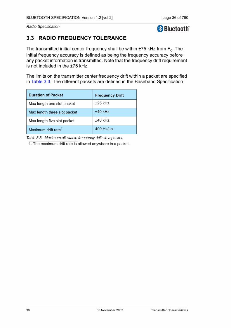
BLUETOOTH SPECIFICATION Version 1.2 [vol 2] page 36 of 790
Radio Specification
3.3 RADIO FREQUENCY TOLERANCE
The transmitted initial center frequency shall be within ±75 kHz from Fc. The initial frequency accuracy is defined as being the frequency accuracy before any packet information is transmitted. Note that the frequency drift requirement is not included in the ±75 kHz.
The limits on the transmitter center frequency drift within a packet are specified in Table 3.3. The different packets are defined in the Baseband Specification.
Duration of Packet Frequency Drift
Max length one slot packet ±25 kHz
Max length three slot packet ±40 kHz
Max length five slot packet ±40 kHz
Maximum drift rate1
1. The maximum drift rate is allowed anywhere in a packet.
400 Hz/µs
Table 3.3: Maximum allowable frequency drifts in a packet.
36 05 November 2003 Transmitter Characteristics

BLUETOOTH SPECIFICATION Version 1.2 [vol 2] page 37 of 790
Radio Specification
4 RECEIVER CHARACTERISTICS
The receiver characteristics shall be measured using loopback as defined in “Test Methodology” on page 233[vol. 3].The reference sensitivity level referred to in this chapter is -70 dBm.
4.1 ACTUAL SENSITIVITY LEVELThe actual sensitivity level is defined as the input level for which a raw bit error rate (BER) of 0.1% is met. The receiver sensitivity shall be below or equal to –70 dBm with any Bluetooth transmitter compliant to the transmitter specification specified in Section 3 on page 33.
4.2 INTERFERENCE PERFORMANCE
The interference performance on Co-channel and adjacent 1 MHz and 2 MHz shall be measured with the wanted signal 10 dB over the reference sensitivity level. For interference performance on all other RF channels the wanted signal shall be 3 dB over the reference sensitivity level. If the frequency of an interfer-ing signal is outside of the band 2400-2483,5 MHz, the out-of-band blocking specification (see Section 4.3 on page 38) shall apply. The interfering signal shall be Bluetooth-modulated (see section 4.7 on page 39). The BER shall be ≤0.1% for all the signal-to-interference ratios listed in Table 4.1:
These specifications are only to be tested at nominal temperature conditions with a device receiving on one RF channel and transmitting on a second RF channel; this means that the synthesizer may change RF channels between reception and transmission, but always returns to the same receive RF channel.
Frequency of Interference Ratio
Co-Channel interference, C/Ico-channel 11 dB
Adjacent (1 MHz) interference, C/I1MHz 0 dB
Adjacent (2 MHz) interference, C/I2MHz -30 dB
Adjacent (≥3 MHz) interference, C/I≥3MHz -40 dB
Image frequency Interference1 2, C/IImage
1. In-band image frequency2. If the image frequency ≠ n*1 MHz, then the image reference frequency is defined as
the closest n*1 MHz frequency.If two adjacent channel specifications from Table 4.1 are applicable to the same chan-nel, the more relaxed specification applies.
-9 dB
Adjacent (1 MHz) interference to in-band image frequency, C/IImage±1MHz
-20 dB
Table 4.1: Interference performance
Receiver Characteristics 05 November 2003 37

BLUETOOTH SPECIFICATION Version 1.2 [vol 2] page 38 of 790
Radio Specification
RF channels where the requirements are not met are called spurious response RF channels. Five spurious response RF channels are allowed at RF channels with a distance of ≥2 MHz from the wanted signal. On these spurious response RF channels a relaxed interference requirement C/I = -17 dB shall be met.
4.3 OUT-OF-BAND BLOCKING
The out-of-band suppression (or rejection) shall be measured with the wanted signal 3 dB over the reference sensitivity level. The interfering signal shall be a continuous wave signal. The BER shall be ≤ 0.1%. The out-of-band blocking shall fulfil the following requirements:
24 exceptions are permitted which are dependent upon the given RF channel and are centered at a frequency which is an integer multiple of 1 MHz. For at least 19 of these spurious response frequencies, a reduced interference level of at least -50dBm is allowed in order to achieve the required BER=0.1% per-formance, whereas for a maximum of 5 of the spurious frequencies the interfer-ence level may be assumed arbitrarily lower.
4.4 INTERMODULATION CHARACTERISTICS
The reference sensitivity performance, BER = 0.1%, shall be met under the fol-lowing conditions:
• The wanted signal shall be at frequency f0 with a power level 6 dB over the reference sensitivity level.
• A static sine wave signal shall be at a frequency f1 with a power level of –39 dBm.
• A Bluetooth modulated signal (see Section 4.7 on page 39) shall be at f2 with a power level of -39 dBm.
Frequencies f0, f1 and f2 shall be chosen such that f0=2f1-f2 and ⎟ f2-f1⎟ =n*1 MHz, where n can be 3, 4, or 5. The system shall fulfill at least one of the three alternatives (n=3,4, or 5).
Interfering Signal Frequency
Interfering Signal Power Level
30 MHz - 2000 MHz -10 dBm
2000 - 2399 MHz -27 dBm
2484 – 3000 MHz -27 dBm
3000 MHz – 12.75 GHz -10 dBm
Table 4.2: Out-of-band suppression (or rejection) requirements.
38 05 November 2003 Receiver Characteristics
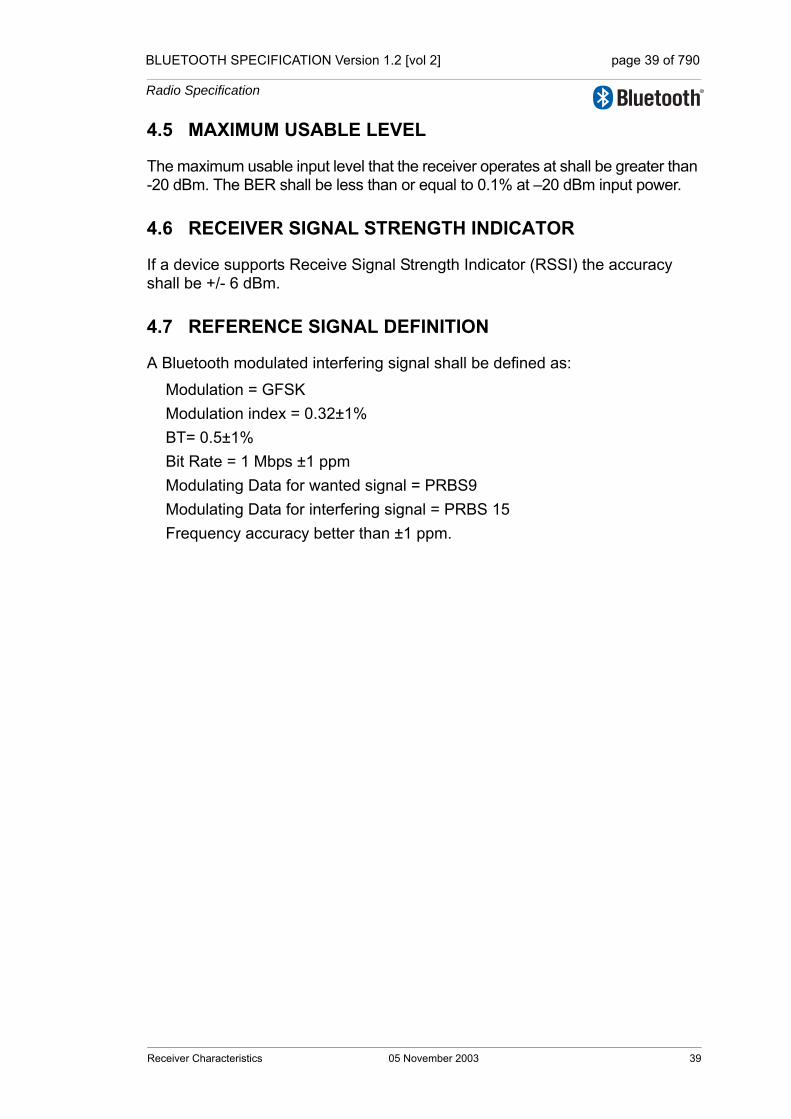
BLUETOOTH SPECIFICATION Version 1.2 [vol 2] page 39 of 790
Radio Specification
4.5 MAXIMUM USABLE LEVEL
The maximum usable input level that the receiver operates at shall be greater than -20 dBm. The BER shall be less than or equal to 0.1% at –20 dBm input power.
4.6 RECEIVER SIGNAL STRENGTH INDICATOR
If a device supports Receive Signal Strength Indicator (RSSI) the accuracy shall be +/- 6 dBm.
4.7 REFERENCE SIGNAL DEFINITION
A Bluetooth modulated interfering signal shall be defined as:
Modulation = GFSKModulation index = 0.32±1%BT= 0.5±1%Bit Rate = 1 Mbps ±1 ppmModulating Data for wanted signal = PRBS9Modulating Data for interfering signal = PRBS 15Frequency accuracy better than ±1 ppm.
Receiver Characteristics 05 November 2003 39

BLUETOOTH SPECIFICATION Version 1.2 [vol 2] page 40 of 790
Radio Specification
40 05 November 2003 Receiver Characteristics

BLUETOOTH SPECIFICATION Version 1.2 [vol 2] page 41 of 790
Radio Specification
5 APPENDIX A
5.1 NOMINAL TEST CONDITIONS
5.1.1 Nominal temperature
The nominal temperature conditions for tests shall be +15 to +35 oC. When it is impractical to carry out the test under this condition a note to this effect, stating the ambient temperature, shall be recorded. The actual value during the test shall be recorded in the test report.
5.1.2 Nominal power source
5.1.2.1 Mains voltage
The nominal test voltage for equipment to be connected to the mains shall be the nominal mains voltage. The nominal voltage shall be the declared voltage or any of the declared voltages for which the equipment was designed. The fre-quency of the test power source corresponding to the AC mains shall be within 2% of the nominal frequency.
5.1.2.2 Lead-acid battery power sources used in vehicles
When radio equipment is intended for operation from the alternator-fed lead-acid battery power sources which are standard in vehicles, then the nominal test voltage shall be 1.1 times the nominal voltage of the battery (6V, 12V, etc.).
5.1.2.3 Other power sources
For operation from other power sources or types of battery (primary or second-ary), the nominal test voltage shall be as declared by the equipment manufac-turer. This shall be recorded in the test report.
Appendix A 05 November 2003 41
BLUETOOTH SPECIFICATION Version 1.2 [vol 2] page 42 of 790
Radio Specification
5.2 EXTREME TEST CONDITIONS
5.2.1 Extreme temperatures
The extreme temperature range shall be the largest temperature range given by the combination of:
• The minimum temperature range 0 °C to +35 °C
• The product operating temperature range declared by the manufacturer.
This extreme temperature range and the declared operating temperature range shall be recorded in the test report.
5.2.2 Extreme power source voltages
Tests at extreme power source voltages specified below are not required when the equipment under test is designed for operation as part of and powered by another system or piece of equipment. Where this is the case, the limit values of the host system or host equipment shall apply. The appropriate limit values shall be declared by the manufacturer and recorded in the test report.
5.2.2.1 Mains voltage
The extreme test voltage for equipment to be connected to an AC mains source shall be the nominal mains voltage ±10%.
5.2.2.2 Lead-acid battery power source used on vehicles
When radio equipment is intended for operation from the alternator-fed lead-acid battery power sources which are standard in vehicles, then extreme test voltage shall be 1.3 and 0.9 times the nominal voltage of the battery (6V, 12V etc.)
5.2.2.3 Power sources using other types of batteries
The lower extreme test voltage for equipment with power sources using the fol-lowing types of battery, shall be
a) for Leclanché, alkaline, or lithium type battery: 0.85 times the nominal voltage of the battery
b) for mercury or nickel-cadmium types of battery: 0.9 times the nominal voltage of the battery.
In both cases, the upper extreme test voltage shall be 1.15 times the nominal voltage of the battery.
5.2.2.4 Other power sources
For equipment using other power sources, or capable of being operated from a variety of power sources (primary or secondary), the extreme test voltages shall be those declared by the manufacturer. These shall be recorded in the test report.
42 05 November 2003 Appendix A
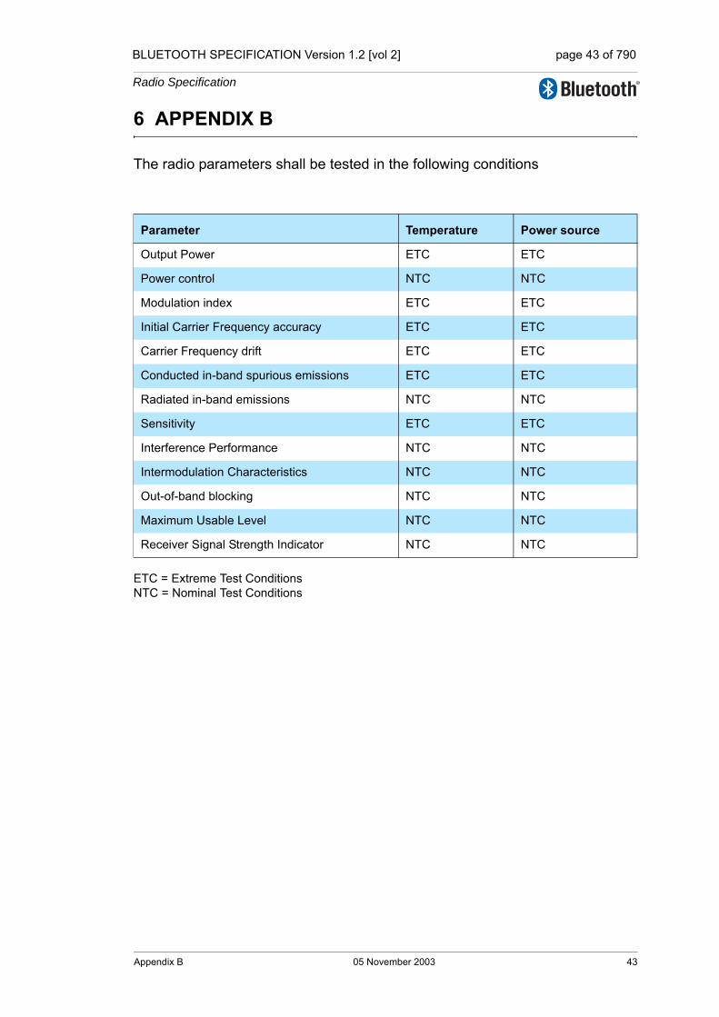
BLUETOOTH SPECIFICATION Version 1.2 [vol 2] page 43 of 790
Radio Specification
6 APPENDIX B
The radio parameters shall be tested in the following conditions
ETC = Extreme Test ConditionsNTC = Nominal Test Conditions
Parameter Temperature Power source
Output Power ETC ETC
Power control NTC NTC
Modulation index ETC ETC
Initial Carrier Frequency accuracy ETC ETC
Carrier Frequency drift ETC ETC
Conducted in-band spurious emissions ETC ETC
Radiated in-band emissions NTC NTC
Sensitivity ETC ETC
Interference Performance NTC NTC
Intermodulation Characteristics NTC NTC
Out-of-band blocking NTC NTC
Maximum Usable Level NTC NTC
Receiver Signal Strength Indicator NTC NTC
Appendix B 05 November 2003 43

BLUETOOTH SPECIFICATION Version 1.2 [vol 2] page 44 of 790
Radio Specification
44 05 November 2003 Appendix B

Core System Package [Controller volume]
Part BBASEBAND SPECIFICATION
This document describes the specification of the Bluetooth link controller which carries out the baseband protocols and other low-level link routines.

BLUETOOTH SPECIFICATION Version 1.2 [vol 2] page 46 of 790
Baseband Specification
46 05 November 2003

BLUETOOTH SPECIFICATION Version 1.2 [vol 2] page 47 of 790
Baseband Specification
CONTENTS
1 General Description ...........................................................................531.1 Bluetooth Clock .........................................................................541.2 Bluetooth Device Addressing.....................................................55
1.2.1 Reserved addresses .....................................................551.3 Access Codes ............................................................................56
2 Physical Channels..............................................................................572.1 Physical Channel Definition .......................................................582.2 Basic Piconet Physical Channel.................................................58
2.2.1 Master-slave definition ..................................................582.2.2 Hopping characteristics ................................................592.2.3 Time slots ......................................................................592.2.4 Piconet clocks ...............................................................602.2.5 Transmit/receive timing .................................................60
2.2.5.1 Piconet physical channel timing .....................612.2.5.2 Piconet physical channel re-synchronization .62
2.3 Adapted Piconet Physical Channel ............................................632.3.1 Hopping characteristics .................................................63
2.4 Page Scan Physical Channel.....................................................642.4.1 Clock estimate for paging..............................................642.4.2 Hopping characteristics .................................................642.4.3 Paging procedure timing ...............................................652.4.4 Page response timing....................................................66
2.5 Inquiry Scan Physical Channel ..................................................682.5.1 Clock for inquiry.............................................................682.5.2 Hopping characteristics .................................................682.5.3 Inquiry procedure timing................................................682.5.4 Inquiry response timing .................................................68
2.6 Hop Selection.............................................................................702.6.1 General selection scheme.............................................702.6.2 Selection kernel ............................................................74
2.6.2.1 First addition operation ...................................742.6.2.2 XOR operation ................................................752.6.2.3 Permutation operation.....................................752.6.2.4 Second addition operation ..............................762.6.2.5 Register bank..................................................76
2.6.3 Adapted hop selection kernel .......................................772.6.3.1 Channel re-mapping function..........................77
05 November 2003 47

BLUETOOTH SPECIFICATION Version 1.2 [vol 2] page 48 of 790
Baseband Specification
2.6.4 Control word..................................................................782.6.4.1 Page scan and inquiry scan hopping
sequences ......................................................792.6.4.2 Page hopping sequence.................................802.6.4.3 Slave page response hopping sequence .......802.6.4.4 Master page response hopping sequence......812.6.4.5 Inquiry hopping sequence ..............................812.6.4.6 Inquiry response hopping sequence...............822.6.4.7 Basic and adapted channel hopping
sequence ........................................................82
3 Physical Links ...................................................................................833.1 Link Supervision ........................................................................83
4 Logical Transports .............................................................................854.1 General ......................................................................................854.2 Logical Transport Address (LT_ADDR) .....................................854.3 Synchronous Logical Transports ...............................................864.4 Asynchronous Logical Transport ...............................................864.5 Transmit/Receive Routines........................................................87
4.5.1 TX Routine ....................................................................874.5.1.1 ACL traffic .......................................................884.5.1.2 SCO traffic ......................................................894.5.1.3 Mixed data/voice traffic ...................................894.5.1.4 eSCO Traffic ...................................................904.5.1.5 Default packet types .......................................90
4.5.2 RX routine .....................................................................904.5.3 Flow control...................................................................91
4.5.3.1 Destination control ..........................................924.5.3.2 Source control ................................................92
4.6 Active Slave Broadcast Transport..............................................924.7 Parked Slave Broadcast Transport ............................................93
4.7.1 Parked member address (PM_ADDR)..........................934.7.2 Access request address (AR_ADDR) ...........................93
5 Logical Links ......................................................................................955.1 Link Control Logical Link (LC)....................................................955.2 ACL Control Logical Link (ACL-C) .............................................955.3 User Asynchronous/Isochronous Logical Link (ACL-U).............95
5.3.1 Pausing the ACL-U logical link......................................965.4 User Synchronous Data Logical Link (SCO-S) .........................965.5 User Extended Synchronous Data Logical Link (eSCO-S) .......965.6 Logical Link Priorities.................................................................96
48 05 November 2003

BLUETOOTH SPECIFICATION Version 1.2 [vol 2] page 49 of 790
Baseband Specification
6 Packets................................................................................................976.1 General Format ..........................................................................976.2 Bit Ordering................................................................................976.3 Access Code..............................................................................98
6.3.1 Access code types ........................................................986.3.2 Preamble .......................................................................996.3.3 Sync word......................................................................99
6.3.3.1 Synchronization word definition ......................996.3.3.2 Pseudo-random noise sequence generation 102
6.3.4 Trailer ..........................................................................1026.4 Packet Header .........................................................................103
6.4.1 LT_ADDR ....................................................................1036.4.2 TYPE...........................................................................1036.4.3 FLOW..........................................................................1046.4.4 ARQN..........................................................................1046.4.5 SEQN ..........................................................................1046.4.6 HEC.............................................................................104
6.5 Packet Types ...........................................................................1056.5.1 Common packet types.................................................106
6.5.1.1 ID packet.......................................................1066.5.1.2 NULL packet .................................................1066.5.1.3 POLL packet .................................................1066.5.1.4 FHS packet ...................................................1066.5.1.5 DM1 packet...................................................108
6.5.2 SCO packets ...............................................................1096.5.2.1 HV1 packet ...................................................1096.5.2.2 HV2 packet ...................................................1096.5.2.3 HV3 packet ...................................................1096.5.2.4 DV packet .....................................................109
6.5.3 eSCO packets .............................................................1106.5.3.1 EV3 packet....................................................1106.5.3.2 EV4 packet....................................................1106.5.3.3 EV5 packet....................................................110
6.5.4 ACL packets ................................................................ 1116.5.4.1 DM1 packet................................................... 1116.5.4.2 DH1 packet ................................................... 1116.5.4.3 DM3 packet................................................... 1116.5.4.4 DH3 packet ................................................... 1116.5.4.5 DM5 packet................................................... 1116.5.4.6 DH5 packet ...................................................1126.5.4.7 AUX1 packet .................................................112
05 November 2003 49
BLUETOOTH SPECIFICATION Version 1.2 [vol 2] page 50 of 790
Baseband Specification
6.6 Payload Format ....................................................................... 1126.6.1 Synchronous data field................................................ 1126.6.2 Asynchronous data field.............................................. 113
6.7 Packet Summary ..................................................................... 116
7 Bitstream Processing ...................................................................... 1177.1 Error Checking......................................................................... 118
7.1.1 HEC generation .......................................................... 1187.1.2 CRC generation .......................................................... 119
7.2 Data Whitening ........................................................................1217.3 Error Correction .......................................................................1227.4 FEC Code: Rate 1/3 ................................................................1227.5 FEC Code: Rate 2/3 ................................................................1237.6 ARQ Scheme...........................................................................124
7.6.1 Unnumbered ARQ.......................................................1247.6.2 Retransmit filtering ......................................................127
7.6.2.1 Initialization of SEQN at start of new connection ....................................................128
7.6.2.2 ACL and SCO retransmit filtering .................1287.6.2.3 eSCO retransmit filtering ..............................1297.6.2.4 FHS retransmit filtering.................................1297.6.2.5 Packets without CRC retransmit filtering ......129
7.6.3 Flushing payloads .......................................................1307.6.4 Multi-slave considerations...........................................1307.6.5 Broadcast packets.......................................................130
8 Link Controller Operation ...............................................................1338.1 Overview of States...................................................................1338.2 Standby State...........................................................................1348.3 Connection Establishment Substates ......................................134
8.3.1 Page scan substate.....................................................1348.3.2 Page substate .............................................................1368.3.3 Page response substates............................................139
8.3.3.1 Slave response substate ..............................1408.3.3.2 Master response substate ............................142
8.4 Device Discovery Substates ....................................................1438.4.1 Inquiry scan substate ..................................................1448.4.2 Inquiry substate...........................................................1458.4.3 Inquiry response substate ...........................................147
8.5 Connection State .....................................................................148
50 05 November 2003

BLUETOOTH SPECIFICATION Version 1.2 [vol 2] page 51 of 790
Baseband Specification
8.6 Active Mode .............................................................................1498.6.1 Polling in the active mode ..........................................1508.6.2 SCO ............................................................................1508.6.3 eSCO ..........................................................................1518.6.4 Broadcast scheme ......................................................1548.6.5 Role switch ..................................................................1558.6.6 Scatternet ....................................................................157
8.6.6.1 Inter-piconet communications.......................1578.6.7 Hop sequence switching .............................................1588.6.8 Channel classification and channel map selection ....1618.6.9 Power Management ....................................................162
8.6.9.1 Packet handling ............................................1628.6.9.2 Slot occupancy..............................................1628.6.9.3 Recommendations for low-power operation .162
8.7 Sniff Mode ................................................................................1638.7.1 Sniff Transition Mode ..................................................164
8.8 Hold Mode................................................................................1658.9 Park State.................................................................................165
8.9.1 Beacon train ................................................................1668.9.2 Beacon access window...............................................1688.9.3 Parked slave synchronization......................................1698.9.4 Parking ........................................................................1708.9.5 Master-initiated unparking ...........................................1718.9.6 Slave-initiated unparking .............................................1718.9.7 Broadcast scan window...............................................1728.9.8 Polling in the park state ...............................................172
9 Audio .................................................................................................1739.1 LOG PCM CODEC...................................................................1739.2 CVSD CODEC .........................................................................1739.3 Error Handling..........................................................................1769.4 General Audio Requirements...................................................176
9.4.1 Signal levels ................................................................1769.4.2 CVSD audio quality .....................................................176
10 List of Figures...................................................................................17711 List of Tables ....................................................................................181
05 November 2003 51

BLUETOOTH SPECIFICATION Version 1.2 [vol 2] page 52 of 790
Baseband Specification
Appendix A: General Audio Recommendations ...........................................................182
Appendix B: Timers .........................................................................................................185
Appendix C: Recommendations for AFH Operation in Park, Hold and Sniff ............187
52 05 November 2003

BLUETOOTH SPECIFICATION Version 1.2 [vol 2] page 53 of 790
Baseband Specification
1 GENERAL DESCRIPTION
This part specifies the normal operation of a Bluetooth baseband.
The Bluetooth system provides a point-to-point connection or a point-to-multi-point connection, see (a) and (b) in Figure 1.1 on page 53. In a point-to-point connection the physical channel is shared between two Bluetooth devices. In a point-to-multipoint connection, the physical channel is shared among several Bluetooth devices. Two or more devices sharing the same physical channel form a piconet. One Bluetooth device acts as the master of the piconet, whereas the other device(s) act as slave(s). Up to seven slaves can be active in the piconet. Additionally, many more slaves can remain connected in a parked state. These parked slaves are not active on the channel, but remain synchronized to the master and can become active without using the connec-tion establishment procedure. Both for active and parked slaves, the channel access is controlled by the master.
Piconets that have common devices are called a scatternet, see (c) in Figure 1.1 on page 53. Each piconet only has a single master, however, slaves can participate in different piconets on a time-division multiplex basis. In addition, a master in one piconet can be a slave in other piconets. Piconets shall not be frequency synchronized and each piconet has its own hopping sequence.
Figure 1.1: Piconets with a single slave operation (a), a multi-slave operation (b) and a scatternet operation (c).
Data is transmitted over the air in packets. The general packet format is shown in Figure 1.2. Each packet consists of 3 entities: the access code, the header, and the payload.
Figure 1.2: Standard packet format.
a b c
Master
Slave
ACCESS CODE
HEADER PAYLOAD
General Description 05 November 2003 53

BLUETOOTH SPECIFICATION Version 1.2 [vol 2] page 54 of 790
Baseband Specification
1.1 BLUETOOTH CLOCK
Every Bluetooth device shall have a native clock that shall be derived from a free running system clock. For synchronization with other devices, offsets are used that, when added to the native clock, provide temporary Bluetooth clocks that are mutually synchronized. It should be noted that the Bluetooth clock has no relation to the time of day; it may therefore be initialized to any value. The clock has a cycle of about a day. If the clock is implemented with a counter, a 28-bit counter is required that shall wrap around at 228-1. The least significant bit (LSB) shall tick in units of 312.5 µs (i.e. half a time slot), giving a clock rate of 3.2 kHz.
The clock determines critical periods and triggers the events in the device. Four periods are important in the Bluetooth system: 312.5 µs, 625 µs, 1.25 ms, and 1.28 s; these periods correspond to the timer bits CLK0, CLK1, CLK2, and CLK12, respectively, see Figure 1.3 on page 54.
Figure 1.3: Bluetooth clock.
In the different modes and states a device can reside in, the clock has different appearances:
• CLKN native clock
• CLKE estimated clock
• CLK master clock
CLKN is the native clock and shall be the reference to all other clock appear-ances. In STANDBY and in Park, Hold and Sniff mode the native clock may be driven by a low power oscillator (LPO) with worst case accuracy (+/-250ppm). Otherwise, the native clock shall be driven by the reference crystal oscillator with worst case accuracy of +/-20ppm.
See Section 2.2.4 on page 60 for the definition of CLK and Section 2.4.1 on page 64 for the definition of CLKE.
The master shall never adjust its native clock during the existence of the pico-net.
µs
µs
12 11 10 6789 5 4 3 2 1 027
1.25ms
1.28s
625
312.5
3.2kHzCLK
54 05 November 2003 General Description
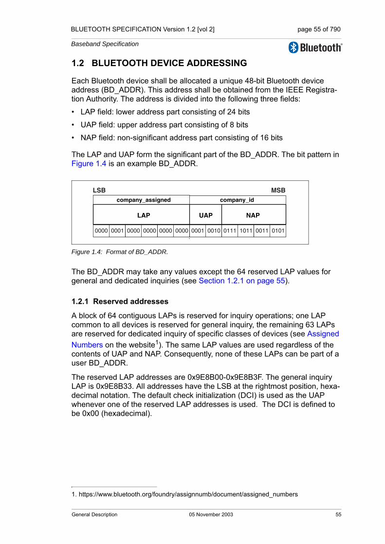
BLUETOOTH SPECIFICATION Version 1.2 [vol 2] page 55 of 790
Baseband Specification
1.2 BLUETOOTH DEVICE ADDRESSING
Each Bluetooth device shall be allocated a unique 48-bit Bluetooth device address (BD_ADDR). This address shall be obtained from the IEEE Registra-tion Authority. The address is divided into the following three fields:
• LAP field: lower address part consisting of 24 bits
• UAP field: upper address part consisting of 8 bits
• NAP field: non-significant address part consisting of 16 bits
The LAP and UAP form the significant part of the BD_ADDR. The bit pattern in Figure 1.4 is an example BD_ADDR.
Figure 1.4: Format of BD_ADDR.
The BD_ADDR may take any values except the 64 reserved LAP values for general and dedicated inquiries (see Section 1.2.1 on page 55).
1.2.1 Reserved addresses
A block of 64 contiguous LAPs is reserved for inquiry operations; one LAP common to all devices is reserved for general inquiry, the remaining 63 LAPs are reserved for dedicated inquiry of specific classes of devices (see Assigned Numbers on the website1). The same LAP values are used regardless of the contents of UAP and NAP. Consequently, none of these LAPs can be part of a user BD_ADDR.
The reserved LAP addresses are 0x9E8B00-0x9E8B3F. The general inquiry LAP is 0x9E8B33. All addresses have the LSB at the rightmost position, hexa-decimal notation. The default check initialization (DCI) is used as the UAP whenever one of the reserved LAP addresses is used. The DCI is defined to be 0x00 (hexadecimal).
1. https://www.bluetooth.org/foundry/assignnumb/document/assigned_numbers
UAP
company_id
LAP
company_assigned
NAP
LSB MSB
0001 0010 0111 1011 0011 01010000 0001 0000 0000 0000 0000
General Description 05 November 2003 55

BLUETOOTH SPECIFICATION Version 1.2 [vol 2] page 56 of 790
Baseband Specification
1.3 ACCESS CODES
In the Bluetooth system all transmissions over the physical channel begin with an access code. Three different access codes are defined, see also Section 6.3.1 on page 98:
• device access code (DAC)
• channel access code (CAC)
• inquiry access code (IAC)
All access codes are derived from the LAP of a device address or an inquiry address. The device access code is used during page, page scan and page response substates and shall be derived from the paged device’s BD_ADDR. The channel access code is used in the CONNECTION state and forms the beginning of all packets exchanged on the piconet physical channel. The chan-nel access code shall be derived from the LAP of the master’s BD_ADDR. Finally, the inquiry access code shall be used in the inquiry substate. There is one general IAC (GIAC) for general inquiry operations and there are 63 dedi-cated IACs (DIACs) for dedicated inquiry operations.
The access code also indicates to the receiver the arrival of a packet. It is used for timing synchronization and offset compensation. The receiver correlates against the entire synchronization word in the access code, providing very robust signalling.
56 05 November 2003 General Description

BLUETOOTH SPECIFICATION Version 1.2 [vol 2] page 57 of 790
Baseband Specification
2 PHYSICAL CHANNELS
The lowest architectural layer in the Bluetooth system is the physical channel. A number of types of physical channel are defined. All Bluetooth physical chan-nels are characterized by the combination of a pseudo-random frequency hop-ping sequence, the specific slot timing of the transmissions, the access code and packet header encoding. These aspects, together with the range of the transmitters, define the signature of the physical channel. For the basic and adapted piconet physical channels frequency hopping is used to change fre-quency periodically to reduce the effects of interference and to satisfy local reg-ulatory requirements.
Two devices that wish to communicate use a shared physical channel for this communication. To achieve this, their transceivers must be tuned to the same RF frequency at the same time, and they must be within a nominal range of each other.
Given that the number of RF carriers is limited and that many Bluetooth devices may be operating independently within the same spatial and temporal area there is a strong likelihood of two independent Bluetooth devices having their transceivers tuned to the same RF carrier, resulting in a physical channel collision. To mitigate the unwanted effects of this collision each transmission on a physical channel starts with an access code that is used as a correlation code by devices tuned to the physical channel. This channel access code is a property of the physical channel. The access code is always present at the start of every transmitted packet.
Four Bluetooth physical channels are defined. Each is optimized and used for a different purpose. Two of these physical channels (the basic piconet channel and adapted piconet channel) are used for communication between connected devices and are associated with a specific piconet. The remaining physical channels are used for discovering (the inquiry scan channel) and connecting (the page scan channel) Bluetooth devices.
A Bluetooth device can only use one of these physical channels at any given time. In order to support multiple concurrent operations the device uses time-division multiplexing between the channels. In this way a Bluetooth device can appear to operate simultaneously in several piconets, as well as being discov-erable and connectable.
Whenever a Bluetooth device is synchronized to the timing, frequency and access code of a physical channel it is said to be 'connected' to this channel (whether or not it is actively involved in communications over the channel.) At a minimum, a device need only be capable of connection to one physical channel at a time, however, advanced devices may be capable of connecting simulta-neously to more than one physical channel, but the specification does not assume that this is possible.
Physical Channels 05 November 2003 57

BLUETOOTH SPECIFICATION Version 1.2 [vol 2] page 58 of 790
Baseband Specification
2.1 PHYSICAL CHANNEL DEFINITION
Physical channels are defined by a pseudo-random RF channel hopping sequence, the packet (slot) timing and an access code. The hopping sequence is determined by the UAP and LAP of a Bluetooth device address and the selected hopping sequence. The phase in the hopping sequence is determined by the Bluetooth clock. All physical channels are subdivided into time slots whose length is different depending on the physical channel. Within the physi-cal channel, each reception or transmission event is associated with a time slot or time slots. For each reception or transmission event an RF channel is selected by the hop selection kernel (see Section 2.6 on page 70).The maxi-mum hop rate is 1600 hops/s in the CONNECTION state and the maximum is 3200 hops/s in the inquiry and page substates.
The following physical channels are defined:
• basic piconet physical channel
• adapted piconet physical channel
• page scan physical channel
• inquiry scan physical channel
2.2 BASIC PICONET PHYSICAL CHANNEL
During the CONNECTION state the basic piconet physical channel is used by default. The adapted piconet physical channel may also be used. The adapted piconet physical channel is identical to the basic piconet physical channel except for the differences listed in Section 2.3 on page 63.
2.2.1 Master-slave definition
The basic piconet physical channel is defined by the master of the piconet. The master controls the traffic on the piconet physical channel by a polling scheme. (see Section 8.5 on page 148)
By definition, the device that initiates a connection by paging is the master. Once a piconet has been established, master-slave roles may be exchanged. This is described in Section 8.6.5 on page 155.
58 05 November 2003 Physical Channels
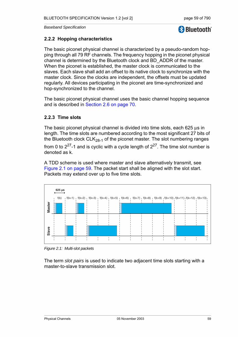
BLUETOOTH SPECIFICATION Version 1.2 [vol 2] page 59 of 790
Baseband Specification
2.2.2 Hopping characteristics
The basic piconet physical channel is characterized by a pseudo-random hop-ping through all 79 RF channels. The frequency hopping in the piconet physical channel is determined by the Bluetooth clock and BD_ADDR of the master. When the piconet is established, the master clock is communicated to the slaves. Each slave shall add an offset to its native clock to synchronize with the master clock. Since the clocks are independent, the offsets must be updated regularly. All devices participating in the piconet are time-synchronized and hop-synchronized to the channel.
The basic piconet physical channel uses the basic channel hopping sequence and is described in Section 2.6 on page 70.
2.2.3 Time slots
The basic piconet physical channel is divided into time slots, each 625 µs in length. The time slots are numbered according to the most significant 27 bits of the Bluetooth clock CLK28-1 of the piconet master. The slot numbering ranges from 0 to 227-1 and is cyclic with a cycle length of 227. The time slot number is denoted as k.
A TDD scheme is used where master and slave alternatively transmit, see Figure 2.1 on page 59. The packet start shall be aligned with the slot start. Packets may extend over up to five time slots.
Figure 2.1: Multi-slot packets
The term slot pairs is used to indicate two adjacent time slots starting with a master-to-slave transmission slot.
f(k)
625
Mas
ter
Sla
ve
µs
f(k+1) f(k+2) f(k+3) f(k+4) f(k+5) f(k+6) f(k+7) f(k+8) f(k+9) f(k+10) f(k+11) f(k+12) f(k+13)
Physical Channels 05 November 2003 59
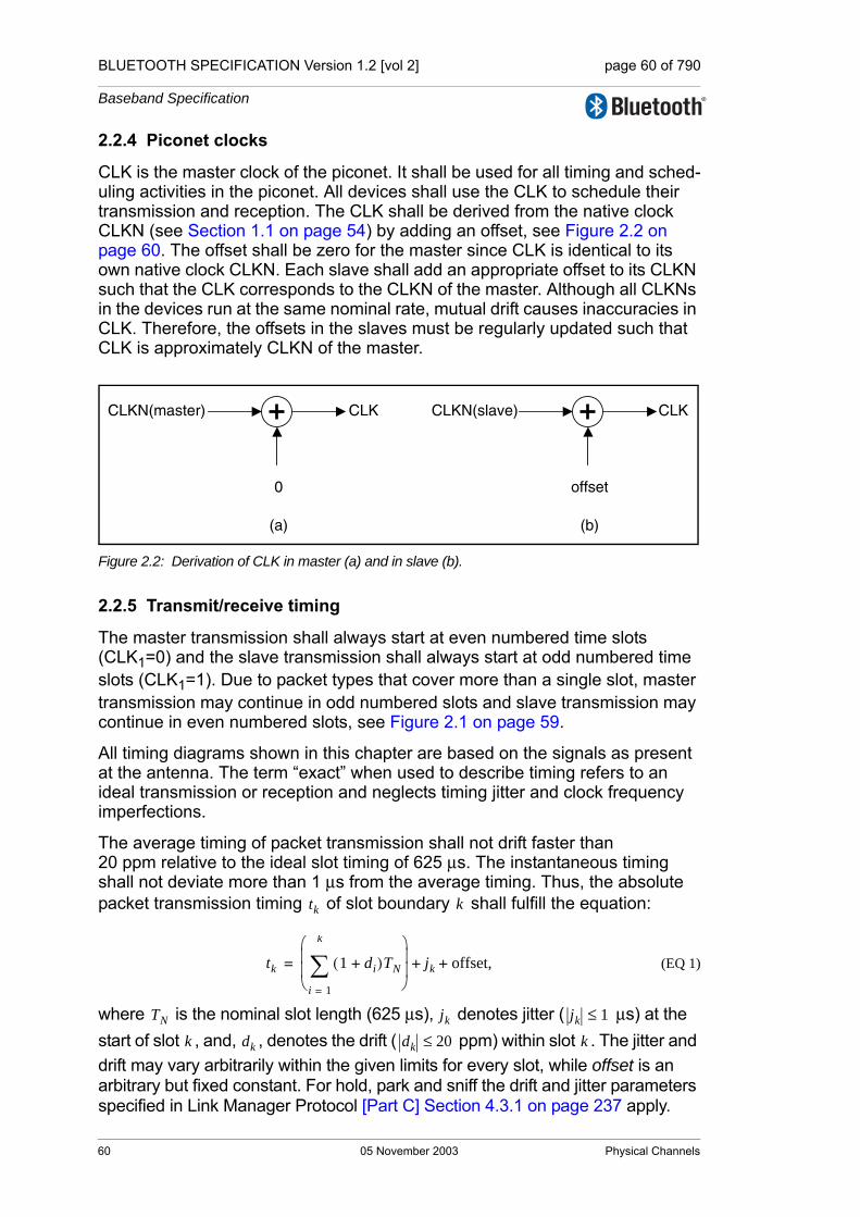
BLUETOOTH SPECIFICATION Version 1.2 [vol 2] page 60 of 790
Baseband Specification
2.2.4 Piconet clocks
CLK is the master clock of the piconet. It shall be used for all timing and sched-uling activities in the piconet. All devices shall use the CLK to schedule their transmission and reception. The CLK shall be derived from the native clock CLKN (see Section 1.1 on page 54) by adding an offset, see Figure 2.2 on page 60. The offset shall be zero for the master since CLK is identical to its own native clock CLKN. Each slave shall add an appropriate offset to its CLKN such that the CLK corresponds to the CLKN of the master. Although all CLKNs in the devices run at the same nominal rate, mutual drift causes inaccuracies in CLK. Therefore, the offsets in the slaves must be regularly updated such that CLK is approximately CLKN of the master.
Figure 2.2: Derivation of CLK in master (a) and in slave (b).
2.2.5 Transmit/receive timing
The master transmission shall always start at even numbered time slots (CLK1=0) and the slave transmission shall always start at odd numbered time slots (CLK1=1). Due to packet types that cover more than a single slot, master transmission may continue in odd numbered slots and slave transmission may continue in even numbered slots, see Figure 2.1 on page 59.
All timing diagrams shown in this chapter are based on the signals as present at the antenna. The term “exact” when used to describe timing refers to an ideal transmission or reception and neglects timing jitter and clock frequency imperfections.
The average timing of packet transmission shall not drift faster than 20 ppm relative to the ideal slot timing of 625 µs. The instantaneous timing shall not deviate more than 1 µs from the average timing. Thus, the absolute packet transmission timing of slot boundary shall fulfill the equation:
(EQ 1)
where is the nominal slot length (625 µs), denotes jitter ( µs) at the start of slot , and, , denotes the drift ( ppm) within slot . The jitter and drift may vary arbitrarily within the given limits for every slot, while offset is an arbitrary but fixed constant. For hold, park and sniff the drift and jitter parameters specified in Link Manager Protocol [Part C] Section 4.3.1 on page 237 apply.
CLKN(master) CLK
0
CLKN(slave) CLK
offset
(a) (b)
tk k
tk 1 di+( )TN
i 1=
k
∑⎝ ⎠⎜ ⎟⎜ ⎟⎛ ⎞
jk offset,+ +=
TN jk jk 1≤
k dk dk 20≤ k
60 05 November 2003 Physical Channels
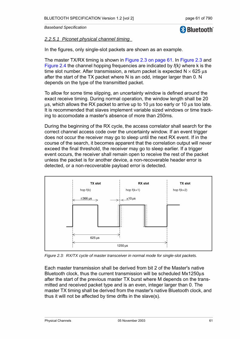
BLUETOOTH SPECIFICATION Version 1.2 [vol 2] page 61 of 790
Baseband Specification
2.2.5.1 Piconet physical channel timing
In the figures, only single-slot packets are shown as an example.
The master TX/RX timing is shown in Figure 2.3 on page 61. In Figure 2.3 and Figure 2.4 the channel hopping frequencies are indicated by f(k) where k is the time slot number. After transmission, a return packet is expected N × 625 µs after the start of the TX packet where N is an odd, integer larger than 0. N depends on the type of the transmitted packet.
To allow for some time slipping, an uncertainty window is defined around the exact receive timing. During normal operation, the window length shall be 20 µs, which allows the RX packet to arrive up to 10 µs too early or 10 µs too late. It is recommended that slaves implement variable sized windows or time track-ing to accomodate a master's absence of more than 250ms.
During the beginning of the RX cycle, the access correlator shall search for the correct channel access code over the uncertainty window. If an event trigger does not occur the receiver may go to sleep until the next RX event. If in the course of the search, it becomes apparent that the correlation output will never exceed the final threshold, the receiver may go to sleep earlier. If a trigger event occurs, the receiver shall remain open to receive the rest of the packet unless the packet is for another device, a non-recoverable header error is detected, or a non-recoverable payload error is detected.
Figure 2.3: RX/TX cycle of master transceiver in normal mode for single-slot packets.
Each master transmission shall be derived from bit 2 of the Master's native Bluetooth clock, thus the current transmission will be scheduled Mx1250µs after the start of the previous master TX burst where M depends on the trans-mitted and received packet type and is an even, integer larger than 0. The master TX timing shall be derived from the master's native Bluetooth clock, and thus it will not be affected by time drifts in the slave(s).
<_366 µs
625 µs
±10 µs
TX slot RX slot TX slot
1250 µs
hop f(k) hop f(k+1) hop f(k+2)
Physical Channels 05 November 2003 61

BLUETOOTH SPECIFICATION Version 1.2 [vol 2] page 62 of 790
Baseband Specification
Slaves maintain an estimate of the master’s native clock by adding a timing off-set to the slave’s native clock (see Section 2.2.4 on page 60). This offset shall be updated each time a packet is received from the master. By comparing the exact RX timing of the received packet with the estimated RX timing, slaves shall correct the offset for any timing misalignments. Since only the channel access code is required to synchronize the slave, slave RX timing can be corrected with any packet sent in the master-to-slave transmission slot.
The slave's TX/RX timing is shown in Figure 2.4 on page 62. The slave’s trans-mission shall be scheduled N × 625µs after the start of the slave’s RX packet where N is an odd, positive integer larger than 0. If the slave’s RX timing drifts, so will its TX timing. During periods when a slave is in the active mode (see Section 8.6 on page 149) and is not able to receive any valid channel access codes from the master, the slave may increase its receive uncertainty window and/or use predicted timing drift to increase the probability of receiving the master's bursts when reception resumes.
Figure 2.4: RX/TX cycle of slave transceiver in normal mode for single-slot packets.
2.2.5.2 Piconet physical channel re-synchronization
In the piconet physical channel, a slave may loose synchronization if it does not receive a packet from the master at least every 250ms (or less if the low power clock is used). This may occur in sniff, hold, park, in a scatternet or due to interference. When re-synchronizing to the piconet physical channel a slave device shall listen for the master before it may send information. In this case, the length of the search window in the slave device may be increased from 20 µs to a larger value X µs as illustrated in Figure 2.5 on page 63. Note that only RX hop frequencies are used. The hop frequency used in the master-to-slave (RX) slot shall also be used in the uncertainty window, even when it is extended into the preceding time interval normally used for the slave-to-master (TX) slot.
625 µs
±10 µs
RX slot TX slot RX slot
1250 µs
hop f(k) hop f(k+1) hop f(k+2)
62 05 November 2003 Physical Channels
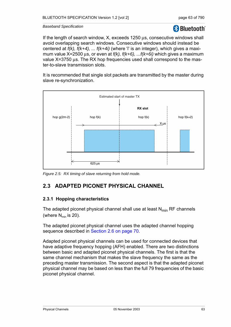
BLUETOOTH SPECIFICATION Version 1.2 [vol 2] page 63 of 790
Baseband Specification
If the length of search window, X, exceeds 1250 µs, consecutive windows shall avoid overlapping search windows. Consecutive windows should instead be centered at f(k), f(k+4), ... f(k+4i) (where 'i' is an integer), which gives a maxi-mum value X=2500 µs, or even at f(k), f(k+6), ...f(k+6i) which gives a maximum value X=3750 µs. The RX hop frequencies used shall correspond to the mas-ter-to-slave transmission slots.
It is recommended that single slot packets are transmitted by the master during slave re-synchronization.
Figure 2.5: RX timing of slave returning from hold mode.
2.3 ADAPTED PICONET PHYSICAL CHANNEL
2.3.1 Hopping characteristics
The adapted piconet physical channel shall use at least Nmin RF channels (where Nmin is 20).
The adapted piconet physical channel uses the adapted channel hopping sequence described in Section 2.6 on page 70.
Adapted piconet physical channels can be used for connected devices that have adaptive frequency hopping (AFH) enabled. There are two distinctions between basic and adapted piconet physical channels. The first is that the same channel mechanism that makes the slave frequency the same as the preceding master transmission. The second aspect is that the adapted piconet physical channel may be based on less than the full 79 frequencies of the basic piconet physical channel.
625 µs
RX slot
hop f(k) hop f(k+2)hop f(k)hop g(2m-2)
X µs
Estimated start of master TX
Physical Channels 05 November 2003 63
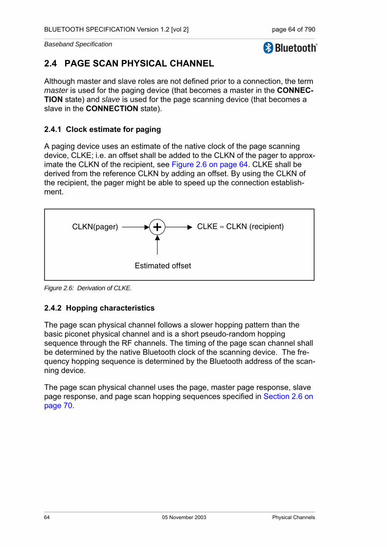
BLUETOOTH SPECIFICATION Version 1.2 [vol 2] page 64 of 790
Baseband Specification
2.4 PAGE SCAN PHYSICAL CHANNEL
Although master and slave roles are not defined prior to a connection, the term master is used for the paging device (that becomes a master in the CONNEC-TION state) and slave is used for the page scanning device (that becomes a slave in the CONNECTION state).
2.4.1 Clock estimate for paging
A paging device uses an estimate of the native clock of the page scanning device, CLKE; i.e. an offset shall be added to the CLKN of the pager to approx-imate the CLKN of the recipient, see Figure 2.6 on page 64. CLKE shall be derived from the reference CLKN by adding an offset. By using the CLKN of the recipient, the pager might be able to speed up the connection establish-ment.
Figure 2.6: Derivation of CLKE.
2.4.2 Hopping characteristics
The page scan physical channel follows a slower hopping pattern than the basic piconet physical channel and is a short pseudo-random hopping sequence through the RF channels. The timing of the page scan channel shall be determined by the native Bluetooth clock of the scanning device. The fre-quency hopping sequence is determined by the Bluetooth address of the scan-ning device.
The page scan physical channel uses the page, master page response, slave page response, and page scan hopping sequences specified in Section 2.6 on page 70.
CLKN(pager) CLKE ≈ CLKN (recipient)
Estimated offset
64 05 November 2003 Physical Channels

BLUETOOTH SPECIFICATION Version 1.2 [vol 2] page 65 of 790
Baseband Specification
2.4.3 Paging procedure timing During the paging procedure, the master shall transmit paging messages (see Table 8.3 on page 139) corresponding to the slave to be connected. Since the paging message is a very short packet, the hop rate is 3200 hops/s. In a single TX slot interval, the paging device shall transmit on two different hop frequen-cies. In Figure 2.7 through Figure 2.11, f(k) is used for the frequencies of the page hopping sequence and f'(k) denotes the corresponding page response sequence frequencies. The first transmission starts where CLK0 = 0 and the second transmission starts where CLK0 = 1.
In a single RX slot interval, the paging device shall listen for the slave page response message on two different hop frequencies. Similar to transmission, the nominal reception starts where CLK0 = 0 and the second reception nomi-nally starts where CLK0 = 1; see Figure 2.7 on page 65. During the TX slot, the paging device shall send the paging message at the TX hop frequencies f(k) and f(k+1). In the RX slot, it shall listen for a response on the corresponding RX hop frequencies f’(k) and f’(k+1). The listening periods shall be exactly timed 625 µs after the corresponding paging packets, and shall include a ±10 µs uncertainty window.
Figure 2.7: RX/TX cycle of transceiver in PAGE mode.
±10 µs
TX slot RX slot TX slot
hop f(k) hop f(k+1) hop f'(k) hop f'(k+1) hop f(k+2)
68 µs
hop f(k+3)
312.5µs
625µs
Physical Channels 05 November 2003 65

BLUETOOTH SPECIFICATION Version 1.2 [vol 2] page 66 of 790
Baseband Specification
2.4.4 Page response timing At connection setup a master page response packet is transmitted from the master to the slave (see Table 8.3 on page 139). This packet establishes the timing and frequency synchronization. After the slave device has received the page message, it shall return a response message that consists of the slave page response packet and shall follow 625 µs after the receipt of the page message. The master shall send the master page response packet in the TX slot following the RX slot in which it received the slave response, according to the RX/TX timing of the master. The time difference between the slave page response and master page response message will depend on the timing of the page message the slave received. In Figure 2.8 on page 66, the slave receives the paging message sent first in the master-to-slave slot. It then responds with a first slave page response packet in the first half of the slave-to-master slot. The timing of the master page response packet is based on the timing of the page message sent first in the preceding master-to-slave slot: there is an exact 1250 µs delay between the first page message and the master page response packet. The packet is sent at the hop frequency f(k+1) which is the hop fre-quency following the hop frequency f(k) the page message was received in.
Figure 2.8: Timing of page response packets on successful page in first half slot
In Figure 2.9 on page 67, the slave receives the paging message sent second in the master-to-slave slot. It then responds with a slave page response packet in the second half of the slave-to-master slot exactly 625 µs after the receipt of the page message. The timing of the master page response packet is still based on the timing of the page message sent first in the preceding master-to-slave slot: there is an exact 1250 µs delay between the first page message and the master page response packet. The packet is sent at the hop frequency f(k+2) which is the hop frequency following the hop frequency f(k+1) the page message was received in.
master-to-slave slot slave-to-master slot master-to-slave slot
hop f(k) hop f(k+1) hop f'(k) hop f(k+1)
68 µs
625 µs 312.5 µs
ID
ID
ID FHS
hop f(k) hop f(k+1)
Master
Slave
66 05 November 2003 Physical Channels

BLUETOOTH SPECIFICATION Version 1.2 [vol 2] page 67 of 790
Baseband Specification
Figure 2.9: Timing of page response packets on successful page in second half slot
The slave shall adjust its RX/TX timing according to the reception of the master page response packet (and not according to the reception of the page mes-sage). That is, the second slave page response message that acknowledges the reception of the master page response packet shall be transmitted 625 µs after the start of the master page response packet.
master-to-slave slot slave-to-master slot master-to-slave slot
68 µs
625µs
ID
ID
ID FHS
Master
Slave
hop f(k) hop f'(k)hop f(k+1)
hop f(k+1)
hop f'(k+1) hop f(k+2)
hop f(k+2)
Physical Channels 05 November 2003 67

BLUETOOTH SPECIFICATION Version 1.2 [vol 2] page 68 of 790
Baseband Specification
2.5 INQUIRY SCAN PHYSICAL CHANNEL
Although master and slave roles are not defined prior to a connection, the term master is used for the inquiring device and slave is used for the inquiry scan-ning device.
2.5.1 Clock for inquiry
The clock used for inquiry and inquiry scan shall be the device's native clock.
2.5.2 Hopping characteristics
The inquiry scan channel follows a slower hopping pattern than the piconet physical channel and is a short pseudo-random hopping sequence through the RF channels. The timing of the inquiry scan channel is determined by the native Bluetooth clock of the scanning device while the frequency hopping sequence is determined by the general inquiry access code.
The inquiry scan physical channel uses the inquiry, inquiry response, and inquiry scan hopping sequences described in Section 2.6 on page 70.
2.5.3 Inquiry procedure timing
During the inquiry procedure, the master shall transmit inquiry messages with the general or dedicated inquiry access code. The timing for inquiry is the same as for paging (see Section 2.4.3 on page 65).
2.5.4 Inquiry response timing
An inquiry response packet is transmitted from the slave to the master after the slave has received an inquiry message (see Table 8.5 on page 147). This packet contains information necessary for the inquiring master to page the slave (see definition of the FHS packet in Section 6.5.1.4 on page 106) and fol-lows 625µs after the receipt of the inquiry message. In figures Figure 2.10 and Figure 2.11, f(k) is used for the frequencies of the inquiry hopping sequence and f'(k) denotes the corresponding inquiry response sequence frequency. The packet is received by the master at the hop frequency f'(k) when the inquiry message received by the slave was first in the master-to-slave slot.
68 05 November 2003 Physical Channels
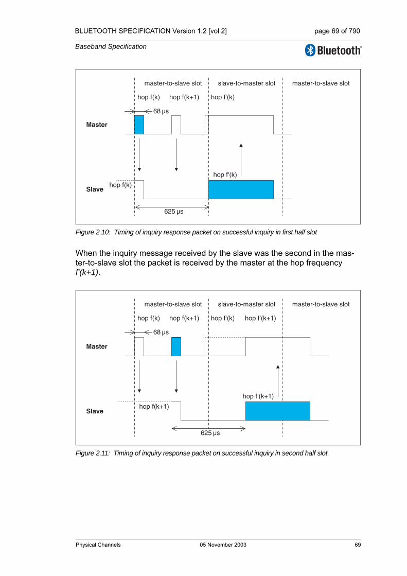
BLUETOOTH SPECIFICATION Version 1.2 [vol 2] page 69 of 790
Baseband Specification
Figure 2.10: Timing of inquiry response packet on successful inquiry in first half slot
When the inquiry message received by the slave was the second in the mas-ter-to-slave slot the packet is received by the master at the hop frequency f'(k+1).
Figure 2.11: Timing of inquiry response packet on successful inquiry in second half slot
Master
Slave
master-to-slave slot slave-to-master slot
hop f(k)
hop f(k) hop f(k+1) hop f'(k)
hop f'(k)
master-to-slave slot
625 µs
68 µs
hop f(k+1)
hop f'(k+1)
hop f'(k+1)
Master
Slave
625 µs
master-to-slave slot slave-to-master slot
hop f(k) hop f(k+1) hop f'(k)
master-to-slave slot
68 µs
Physical Channels 05 November 2003 69
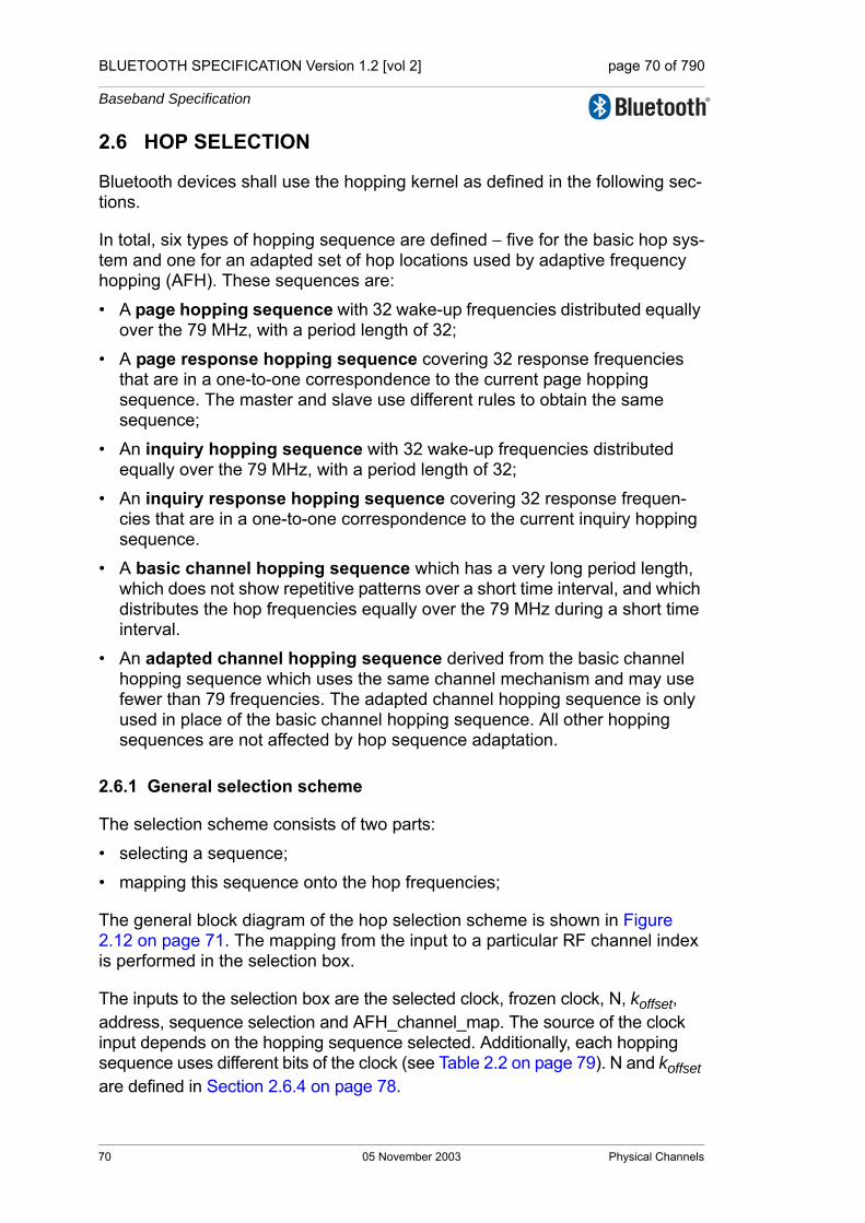
BLUETOOTH SPECIFICATION Version 1.2 [vol 2] page 70 of 790
Baseband Specification
2.6 HOP SELECTION
Bluetooth devices shall use the hopping kernel as defined in the following sec-tions.
In total, six types of hopping sequence are defined − five for the basic hop sys-tem and one for an adapted set of hop locations used by adaptive frequency hopping (AFH). These sequences are:
• A page hopping sequence with 32 wake-up frequencies distributed equally over the 79 MHz, with a period length of 32;
• A page response hopping sequence covering 32 response frequencies that are in a one-to-one correspondence to the current page hopping sequence. The master and slave use different rules to obtain the same sequence;
• An inquiry hopping sequence with 32 wake-up frequencies distributed equally over the 79 MHz, with a period length of 32;
• An inquiry response hopping sequence covering 32 response frequen-cies that are in a one-to-one correspondence to the current inquiry hopping sequence.
• A basic channel hopping sequence which has a very long period length, which does not show repetitive patterns over a short time interval, and which distributes the hop frequencies equally over the 79 MHz during a short time interval.
• An adapted channel hopping sequence derived from the basic channel hopping sequence which uses the same channel mechanism and may use fewer than 79 frequencies. The adapted channel hopping sequence is only used in place of the basic channel hopping sequence. All other hopping sequences are not affected by hop sequence adaptation.
2.6.1 General selection scheme
The selection scheme consists of two parts:
• selecting a sequence;
• mapping this sequence onto the hop frequencies;
The general block diagram of the hop selection scheme is shown in Figure 2.12 on page 71. The mapping from the input to a particular RF channel index is performed in the selection box.
The inputs to the selection box are the selected clock, frozen clock, N, koffset, address, sequence selection and AFH_channel_map. The source of the clock input depends on the hopping sequence selected. Additionally, each hopping sequence uses different bits of the clock (see Table 2.2 on page 79). N and koffset are defined in Section 2.6.4 on page 78.
70 05 November 2003 Physical Channels
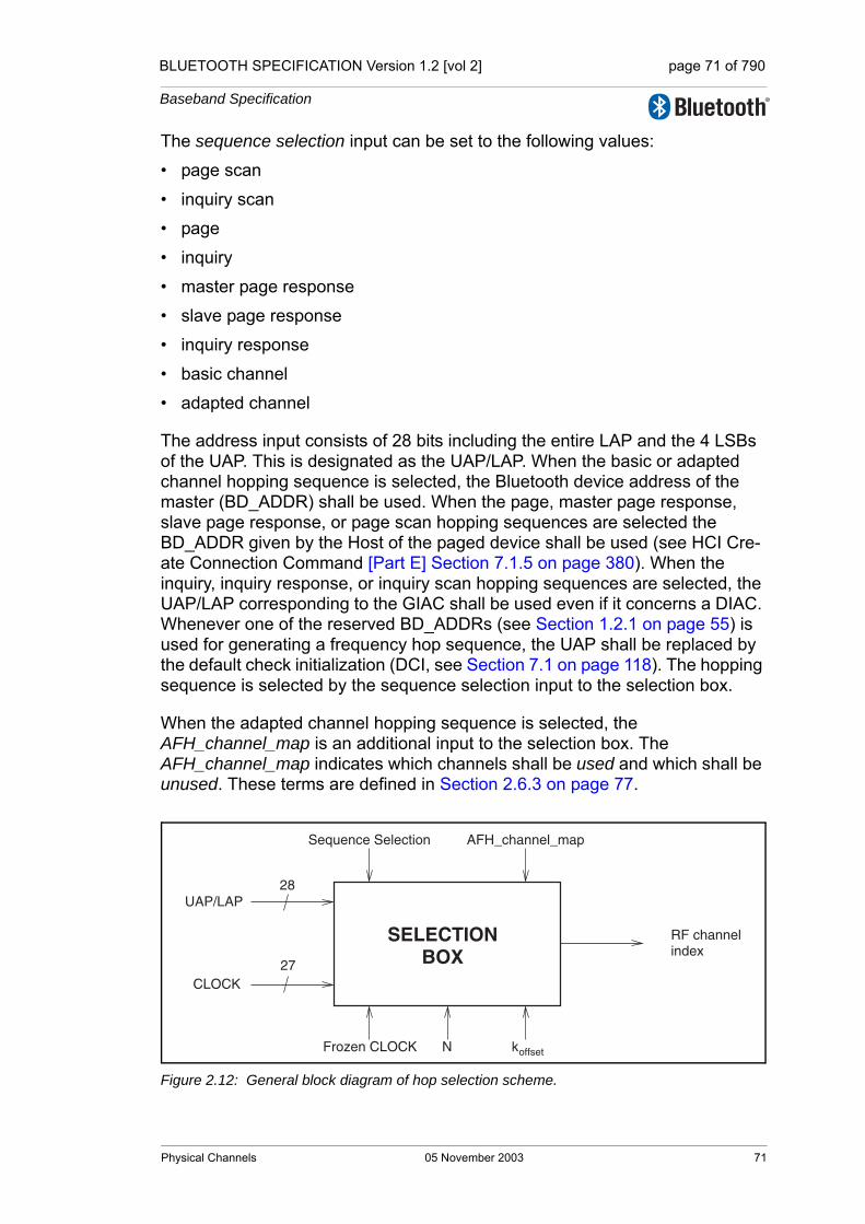
BLUETOOTH SPECIFICATION Version 1.2 [vol 2] page 71 of 790
Baseband Specification
The sequence selection input can be set to the following values:
• page scan
• inquiry scan
• page
• inquiry
• master page response
• slave page response
• inquiry response
• basic channel
• adapted channel
The address input consists of 28 bits including the entire LAP and the 4 LSBs of the UAP. This is designated as the UAP/LAP. When the basic or adapted channel hopping sequence is selected, the Bluetooth device address of the master (BD_ADDR) shall be used. When the page, master page response, slave page response, or page scan hopping sequences are selected the BD_ADDR given by the Host of the paged device shall be used (see HCI Cre-ate Connection Command [Part E] Section 7.1.5 on page 380). When the inquiry, inquiry response, or inquiry scan hopping sequences are selected, the UAP/LAP corresponding to the GIAC shall be used even if it concerns a DIAC. Whenever one of the reserved BD_ADDRs (see Section 1.2.1 on page 55) is used for generating a frequency hop sequence, the UAP shall be replaced by the default check initialization (DCI, see Section 7.1 on page 118). The hopping sequence is selected by the sequence selection input to the selection box.
When the adapted channel hopping sequence is selected, the AFH_channel_map is an additional input to the selection box. The AFH_channel_map indicates which channels shall be used and which shall be unused. These terms are defined in Section 2.6.3 on page 77.
Figure 2.12: General block diagram of hop selection scheme.
SELECTIONBOX
RF channel index
UAP/LAP
Sequence Selection AFH_channel_map
CLOCK27
28
NFrozen CLOCK koffset
Physical Channels 05 November 2003 71

BLUETOOTH SPECIFICATION Version 1.2 [vol 2] page 72 of 790
Baseband Specification
The output, RF channel index, constitutes a pseudo-random sequence. The RF channel index is mapped to RF channel frequencies using the equation in Table 2.1 on page 31 in the Radio Specification.
The selection scheme chooses a segment of 32 hop frequencies spanning about 64 MHz and visits these hops in a pseudo-random order. Next, a differ-ent 32-hop segment is chosen, etc. In the page, master page response, slave page response, page scan, inquiry, inquiry response and inquiry scan hopping sequences, the same 32-hop segment is used all the time (the segment is selected by the address; different devices will have different paging segments). When the basic channel hopping sequence is selected, the output constitutes a pseudo-random sequence that slides through the 79 hops. The principle is depicted in Figure 2.13 on page 72..
Figure 2.13: Hop selection scheme in CONNECTION state.
The RF frequency shall remain fixed for the duration of the packet. The RF fre-quency for the packet shall be derived from the Bluetooth clock value in the first slot of the packet. The RF frequency in the first slot after a multi-slot packet shall use the frequency as determined by the Bluetooth clock value for that slot. Figure 2.14 on page 73 illustrates the hop definition on single- and multi-slot packets.
0 4 6 62 642 78 1 73 75 77
segment 1
segment 2
segment 3
∆
32 16
segment length ∆
72 05 November 2003 Physical Channels
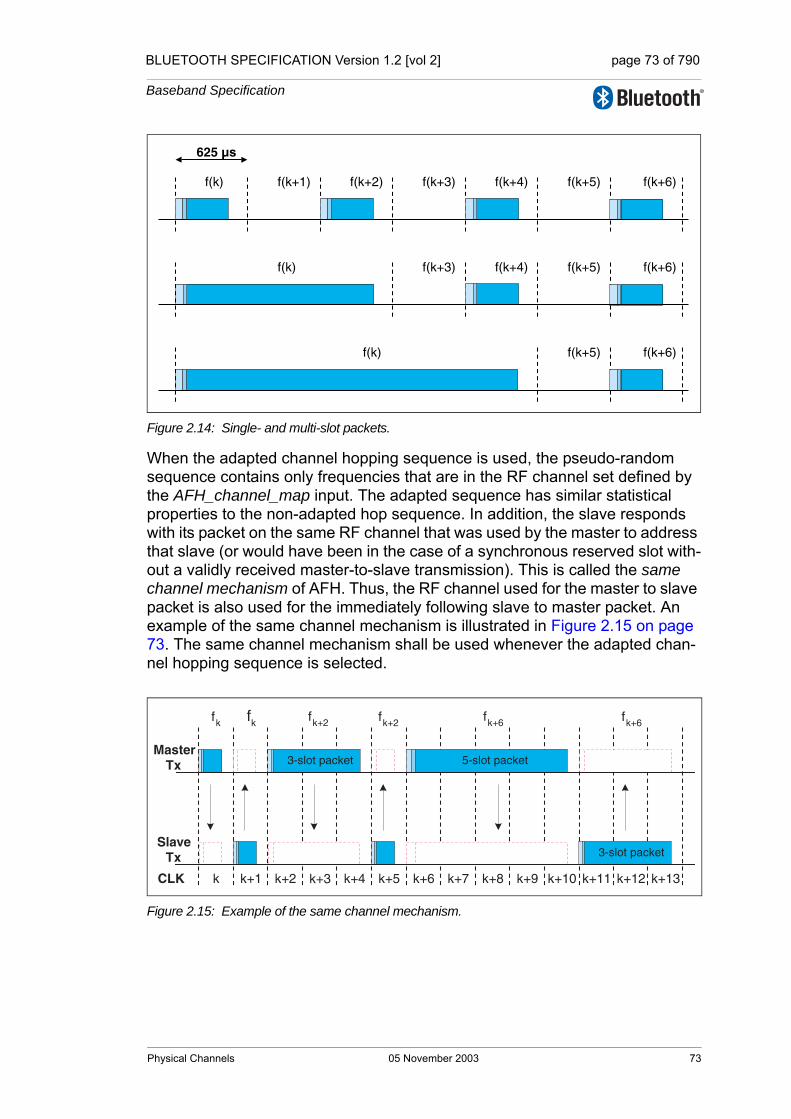
BLUETOOTH SPECIFICATION Version 1.2 [vol 2] page 73 of 790
Baseband Specification
Figure 2.14: Single- and multi-slot packets.
When the adapted channel hopping sequence is used, the pseudo-random sequence contains only frequencies that are in the RF channel set defined by the AFH_channel_map input. The adapted sequence has similar statistical properties to the non-adapted hop sequence. In addition, the slave responds with its packet on the same RF channel that was used by the master to address that slave (or would have been in the case of a synchronous reserved slot with-out a validly received master-to-slave transmission). This is called the same channel mechanism of AFH. Thus, the RF channel used for the master to slave packet is also used for the immediately following slave to master packet. An example of the same channel mechanism is illustrated in Figure 2.15 on page 73. The same channel mechanism shall be used whenever the adapted chan-nel hopping sequence is selected.
Figure 2.15: Example of the same channel mechanism.
f(k)
625 µs
f(k+1) f(k+2) f(k+3) f(k+4) f(k+5)
f(k) f(k+3) f(k+4) f(k+5)
f(k) f(k+5)
f(k+6)
f(k+6)
f(k+6)
3-slot packet 5-slot packet
3-slot packet
fk fk fk+2 fk+6fk+2 fk+6
k k+1 k+2 k+3 k+5k+4 k+6 k+7 k+8 k+9 k+10 k+11 k+12CLK k+13
SlaveTx
MasterTx
Physical Channels 05 November 2003 73
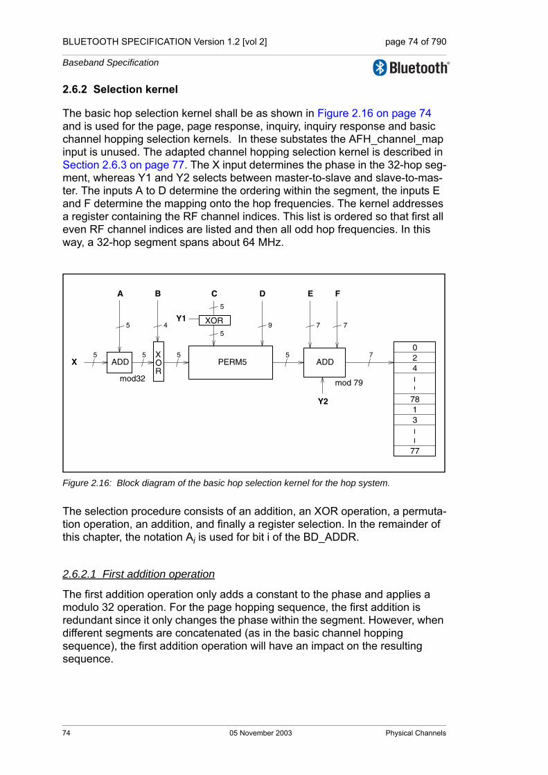
BLUETOOTH SPECIFICATION Version 1.2 [vol 2] page 74 of 790
Baseband Specification
2.6.2 Selection kernel
The basic hop selection kernel shall be as shown in Figure 2.16 on page 74 and is used for the page, page response, inquiry, inquiry response and basic channel hopping selection kernels. In these substates the AFH_channel_map input is unused. The adapted channel hopping selection kernel is described in Section 2.6.3 on page 77. The X input determines the phase in the 32-hop seg-ment, whereas Y1 and Y2 selects between master-to-slave and slave-to-mas-ter. The inputs A to D determine the ordering within the segment, the inputs E and F determine the mapping onto the hop frequencies. The kernel addresses a register containing the RF channel indices. This list is ordered so that first all even RF channel indices are listed and then all odd hop frequencies. In this way, a 32-hop segment spans about 64 MHz.
Figure 2.16: Block diagram of the basic hop selection kernel for the hop system.
The selection procedure consists of an addition, an XOR operation, a permuta-tion operation, an addition, and finally a register selection. In the remainder of this chapter, the notation Ai is used for bit i of the BD_ADDR.
2.6.2.1 First addition operation
The first addition operation only adds a constant to the phase and applies a modulo 32 operation. For the page hopping sequence, the first addition is redundant since it only changes the phase within the segment. However, when different segments are concatenated (as in the basic channel hopping sequence), the first addition operation will have an impact on the resulting sequence.
XOR
XOR
55X ADD
mod32
A B
4
55
5
ADD
E F
7
7
7
024
C D
59
5
Y1
Y2
mod 79
178
3
77
PERM5
74 05 November 2003 Physical Channels

BLUETOOTH SPECIFICATION Version 1.2 [vol 2] page 75 of 790
Baseband Specification
2.6.2.2 XOR operation
Let Z’ denote the output of the first addition. In the XOR operation, the four LSBs of Z’ are modulo-2 added to the address bits A22-19. The operation is illustrated in Figure 2.17 on page 75.
Figure 2.17: XOR operation for the hop system.
2.6.2.3 Permutation operation
The permutation operation involves the switching from 5 inputs to 5 outputs for the hop system, controlled by the control word. The permutation or switching box shall be as shown in Figure 2.18 on page 76. It consists of 7 stages of but-terfly operations. The control of the butterflies by the control signals P is shown in Table 2.1. P0-8 corresponds to D0-8, and, corresponds to for
in Figure 2.16 .
The Z input is the output of the XOR operation as described in the previous section. The butterfly operation can be implemented with multiplexers as depicted in Figure 2.19 on page 76.
Control signal Butterfly
Control signal Butterfly
P0 {Z0,Z1} P8 {Z1,Z4}
P1 {Z2,Z3} P9 {Z0,Z3}
P2 {Z1,Z2} P10 {Z2,Z4}
P3 {Z3,Z4} P11 {Z1,Z3}
P4 {Z0,Z4} P12 {Z0,Z3}
P5 {Z1,Z3} P13 {Z1,Z2}
P6 {Z0,Z2}
P7 {Z3,Z4}
Table 2.1: Control of the butterflies for the hop system
xor
A
Z'
Z'
Z'
Z'
Z'
22-19
0
1
2
3
4
Z
Z
Z
Z
Z
0
1
2
3
4
Pi 9+ Ci Y1⊕
i 0…4=
Physical Channels 05 November 2003 75

BLUETOOTH SPECIFICATION Version 1.2 [vol 2] page 76 of 790
Baseband Specification
Figure 2.18: Permutation operation for the hop system.
Figure 2.19: Butterfly implementation.
2.6.2.4 Second addition operation
The addition operation only adds a constant to the output of the permutation operation. The addition is applied modulo 79.
2.6.2.5 Register bank
The output of the adder addresses a bank of 79 registers. The registers are loaded with the synthesizer code words corresponding to the hop frequencies 0 to 78. Note that the upper half of the bank contains the even hop frequencies, whereas the lower half of the bank contains the odd hop frequencies.
stage 1 2 3 4 5 6 7
13 12 11 10 9 8 7 6 45 23 01
0
1
2
3
4
Z
Z
Z
Z
Z
P P P P P P P P P P P P P P
01
01
P
76 05 November 2003 Physical Channels

BLUETOOTH SPECIFICATION Version 1.2 [vol 2] page 77 of 790
Baseband Specification
2.6.3 Adapted hop selection kernel
The adapted hop selection kernel is based on the basic hop selection kernel defined in the preceding sections.
The inputs to the adapted hop selection kernel are the same as for the basic hop system kernel except that the input AFH_channel_map (defined in Link Manager Protocol [Part C] Section 5.2 on page 277) is used. The AFH_channel_map indicates which RF channels shall be used and which shall be unused. When hop sequence adaptation is enabled, the number of used RF channels may be reduced from 79 to some smaller value N. All devices shall be capable of operating on an adapted hop sequence (AHS) with Nmin ≤ N ≤ 79, with any combination of used RF channels within the AFH_channel_map that meets this constraint. Nmin is defined in Section 2.3.1 on page 63.
Adaptation of the hopping sequence is achieved through two additions to the basic channel hopping sequence according to Figure 2.16 on page 74:
• Unused RF channels are re-mapped uniformly onto used RF channels. That is, if the hop selection kernel of the basic system generates an unused RF channel, an alternative RF channel out of the set of used RF channels is selected pseudo-randomly.
• The used RF channel generated for the master-to-slave packet is also used for the immediately following slave-to-master packet (see Section 2.6.1 on page 70).
2.6.3.1 Channel re-mapping function
When the adapted hop selection kernel is selected, the basic hop selection ker-nel according to Figure 2.16 on page 74 is initially used to determine an RF channel. If this RF channel is unused according to the AFH_channel_map, the unused RF channel is re-mapped by the re-mapping function to one of the used RF channels. If the RF channel determined by the basic hop selection kernel is already in the set of used RF channels, no adjustment is made. The hop sequence of the (non-adapted) basic hop equals the sequence of the adapted selection kernel on all locations where used RF channels are gener-ated by the basic hop. This property facilitates non-AFH slaves remaining syn-chronized while other slaves in the piconet are using the adapted hopping sequence.
A block diagram of the re-mapping mechanism is shown in Figure 2.20 on page 78. The re-mapping function is a post-processing step to the selection kernel from Figure 2.16 on page 74, denoted as ‘Hop selection of the basic hop’. The output fk of the basic hop selection kernel is an RF channel number that ranges between 0 and 78. This RF channel will either be in the set of used RF channels or in the set of unused RF channels.
Physical Channels 05 November 2003 77
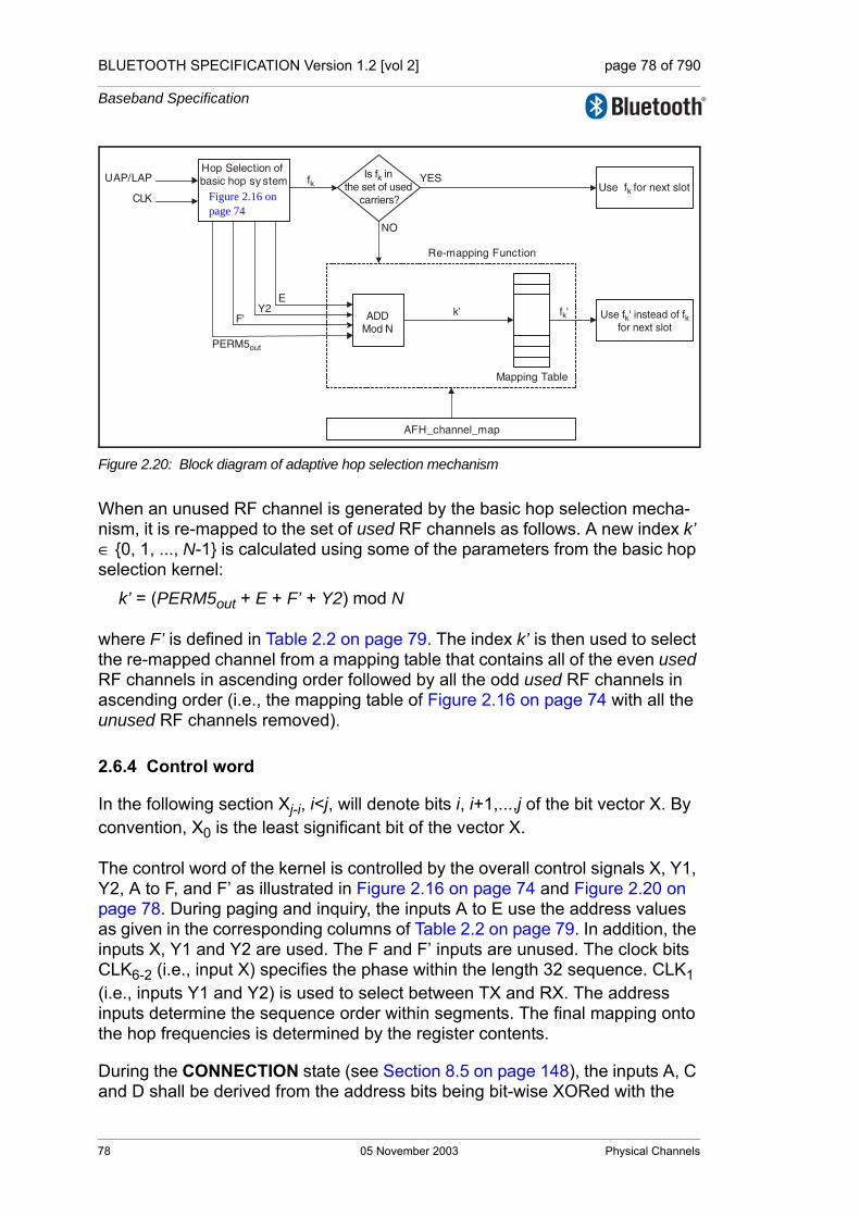
BLUETOOTH SPECIFICATION Version 1.2 [vol 2] page 78 of 790
Baseband Specification
Figure 2.20: Block diagram of adaptive hop selection mechanism
When an unused RF channel is generated by the basic hop selection mecha-nism, it is re-mapped to the set of used RF channels as follows. A new index k’ ∈ {0, 1, ..., N-1} is calculated using some of the parameters from the basic hop selection kernel:
k’ = (PERM5out + E + F’ + Y2) mod N
where F’ is defined in Table 2.2 on page 79. The index k’ is then used to select the re-mapped channel from a mapping table that contains all of the even used RF channels in ascending order followed by all the odd used RF channels in ascending order (i.e., the mapping table of Figure 2.16 on page 74 with all the unused RF channels removed).
2.6.4 Control word
In the following section Xj-i, i<j, will denote bits i, i+1,...,j of the bit vector X. By convention, X0 is the least significant bit of the vector X.
The control word of the kernel is controlled by the overall control signals X, Y1, Y2, A to F, and F’ as illustrated in Figure 2.16 on page 74 and Figure 2.20 on page 78. During paging and inquiry, the inputs A to E use the address values as given in the corresponding columns of Table 2.2 on page 79. In addition, the inputs X, Y1 and Y2 are used. The F and F’ inputs are unused. The clock bits CLK6-2 (i.e., input X) specifies the phase within the length 32 sequence. CLK1 (i.e., inputs Y1 and Y2) is used to select between TX and RX. The address inputs determine the sequence order within segments. The final mapping onto the hop frequencies is determined by the register contents.
During the CONNECTION state (see Section 8.5 on page 148), the inputs A, C and D shall be derived from the address bits being bit-wise XORed with the
AFH_channel_map
Hop Selection of basic hop sy stem
CLK
UAP/LAP
EY2
PERM5out
Is fk in the set of used
carriers?
Mapping Table
Re-mapping Function
YES
NO
Use fk for next slot
Use fk' instead of fkfor next slot
fk
ADDMod N
F'k' fk'
Figure 2.16 on page 74
78 05 November 2003 Physical Channels
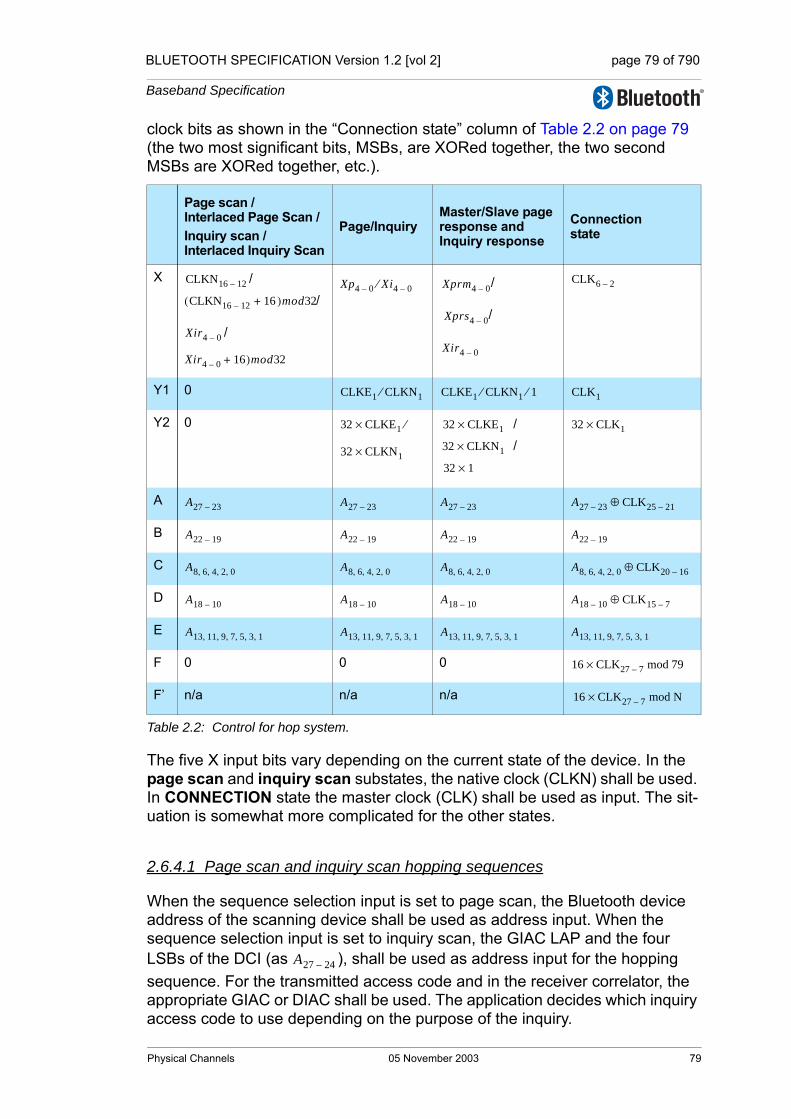
BLUETOOTH SPECIFICATION Version 1.2 [vol 2] page 79 of 790
Baseband Specification
clock bits as shown in the “Connection state” column of Table 2.2 on page 79 (the two most significant bits, MSBs, are XORed together, the two second MSBs are XORed together, etc.).
The five X input bits vary depending on the current state of the device. In the page scan and inquiry scan substates, the native clock (CLKN) shall be used. In CONNECTION state the master clock (CLK) shall be used as input. The sit-uation is somewhat more complicated for the other states.
2.6.4.1 Page scan and inquiry scan hopping sequences
When the sequence selection input is set to page scan, the Bluetooth device address of the scanning device shall be used as address input. When the sequence selection input is set to inquiry scan, the GIAC LAP and the four LSBs of the DCI (as ), shall be used as address input for the hopping sequence. For the transmitted access code and in the receiver correlator, the appropriate GIAC or DIAC shall be used. The application decides which inquiry access code to use depending on the purpose of the inquiry.
Page scan / Interlaced Page Scan /Inquiry scan / Interlaced Inquiry Scan
Page/InquiryMaster/Slave page response and Inquiry response
Connectionstate
X //
/
/
/
Y1 0
Y2 0 //
A
B
C
D
E
F 0 0 0
F’ n/a n/a n/a
Table 2.2: Control for hop system.
CLKN16 12–
CLKN16 12–( 16 )mod32+
Xir4 0–
Xir4 0– 16+ )mod32
Xp4 0– Xi4 0–⁄ Xprm4 0–
Xprs4 0–
Xir4 0–
CLK6 2–
CLKE1 CLKN1⁄ CLKE1 CLKN1⁄ 1⁄ CLK1
32 CLKE1× ⁄
32 CLKN1×
32 CLKE1×
32 CLKN1×
32 1×
32 CLK1×
A27 23– A27 23– A27 23– A27 23– CLK25 21–⊕
A22 19– A22 19– A22 19– A22 19–
A8 6 4 2 0, , , , A8 6 4 2 0, , , , A8 6 4 2 0, , , , A8 6 4 2 0, , , , CLK20 16–⊕
A18 10– A18 10– A18 10– A18 10– CLK15 7–⊕
A13 11 9 7 5 3 1, , , , , , A13 11 9 7 5 3 1, , , , , , A13 11 9 7 5 3 1, , , , , , A13 11 9 7 5 3 1, , , , , ,
16 CLK27 7–× mod 79
16 CLK27 7–× mod N
A27 24–
Physical Channels 05 November 2003 79

BLUETOOTH SPECIFICATION Version 1.2 [vol 2] page 80 of 790
Baseband Specification
2.6.4.2 Page hopping sequence
When the sequence selection input is set to page, the paging device shall start using the A-train, i.e., , where is the source’s estimate of the current receiver frequency in the paged device. The index k is a function of all the inputs in Figure 2.16. There are 32 possible paging frequen-cies within each 1.28 second interval. Half of these frequencies belong to the A-train, the rest (i.e., ) belong to the B-train. In order to achieve the -8 offset of the A-train, a constant of 24 shall be added to the clock bits (which is equivalent to -8 due to the modulo 32 opera-tion). The B-train is obtained by setting the offset to 8. A cyclic shift of the order within the trains is also necessary in order to avoid a possible repetitive mis-match between the paging and scanning devices. Thus,
(EQ 2)
where
(EQ 3)
Alternatively, each switch between the A- and B-trains may be accomplished by adding 16 to the current value of (originally initialized with 24).
2.6.4.3 Slave page response hopping sequence
When the sequence selection input is set to slave page response, in order to eliminate the possibility of losing the link due to discrepancies of the native clock CLKN and the master’s clock estimate CLKE, the four bits shall be frozen at their current value. The value shall be frozen at the content it has in the slot where the recipient’s access code is detected. The native clock shall not be stopped; it is merely the values of the bits used for creating the X-input that are kept fixed for a while. A frozen value is denoted by an asterisk (*) in the discussion below.
For each response slot the paged device shall use an X-input value one larger (modulo 32) than in the preceding response slot. However, the first response shall be made with the X-input kept at the same value as it was when the access code was recognized. Let be a counter starting at zero. Then, the X-input in the -th response slot (the first response slot being the one imme-diately following the page slot now responding to) of the slave response sub-state is:
(EQ 4)
f k 8–( ) … f k( ) … f k 7+( ), , , ,{ } f k( )
f k 8+( ) … f k 15+( ), , f, k 16–( ) … f k 9–( ), ,{ }
Xp CLKE16 12– koffset CLKE4 2– 0, CLKE16 12––( ) mod 16+ +[ ] mod 32,=
koffset24 A-train,8 B-train.⎩
⎨⎧
=
koffset
CLKN16 12–
NN 1+( )
Xprs CLKN∗16 12– N+[ ] mod 32,=
80 05 November 2003 Physical Channels

BLUETOOTH SPECIFICATION Version 1.2 [vol 2] page 81 of 790
Baseband Specification
The counter shall be set to zero in the slot where the slave acknowledges the page (see Figure 8.3 on page 140 and Figure 8.4 on page 140). Then, the value of shall be increased by one each time is set to zero, which corresponds to the start of a master TX slot. The X-input shall be constructed this way until the first FHS packet is received and the immediately following response packet has been transmitted. After this the slave shall enter the CONNECTION state using the parameters received in the FHS packet.
2.6.4.4 Master page response hopping sequence
When the sequence selection input is set to master page response, the master shall freeze its estimated slave clock to the value that triggered a response from the paged device. It is equivalent to using the values of the clock estimate when receiving the slave response (since only will differ from the corre-sponding page transmission). Thus, the values are frozen when the slave ID packet is received. In addition to the clock bits used, the current value of shall also be frozen. The master shall adjust its X-input in the same way the paged device does, i.e., by incrementing this value by one for each time is set to zero. The first increment shall be done before sending the FHS packet to the paged device. Let be a counter starting at one. The rule for forming the X-input is:
(EQ 5)
The value of shall be increased each time is set to zero, which corre-sponds to the start of a master TX slot.
2.6.4.5 Inquiry hopping sequence
When the sequence selection input is set to inquiry, the X-input is similar to that used in the page hopping sequence. Since no particular device is addressed, the native clock CLKN of the inquirer shall be used. Moreover, which of the two train offsets to start with is of no real concern in this state. Consequently,
(EQ 6)
where is defined by (EQ 3) on page 80. The initial choice of the offset is arbitrary.
The GIAC LAP and the four LSBs of the DCI (as ) shall be used as address input for the hopping sequence generator.
N
N CLKN1
CLKE1
koffset
CLKE1
N
Xprm CLKE[ ∗16 12– koffset∗ + +=
CLKE∗4 2– 0, CLKE∗16 12––( ) mod 16 N+ ] mod 32,
N CLKE1
Xi CLKN16 12– koffset CLKN4 2– 0, CLKN16 12––( ) mod 16+ +[ ] mod 32,=
koffset
A27 24–
Physical Channels 05 November 2003 81

BLUETOOTH SPECIFICATION Version 1.2 [vol 2] page 82 of 790
Baseband Specification
2.6.4.6 Inquiry response hopping sequence
The inquiry response hopping sequence is similar to the slave page response hopping sequence with respect to the X-input. The clock input shall not be fro-zen, thus the following equation apply:
(EQ 7)
Furthermore, the counter is increased not on basis, but rather after each FHS packet has been transmitted in response to the inquiry. There is no restriction on the initial value of as it is independent of the corresponding value in the inquiring unit.
The GIAC LAP and the four LSBs of the DCI (as ) shall be used as address input for the hopping sequence generator. The other input bits to the generator shall be the same as for page response.
2.6.4.7 Basic and adapted channel hopping sequence
In the basic and adapted channel hopping sequences, the clock bits to use in the basic or adapted hopping sequence generation shall always be derived from the master clock, CLK. The address bits shall be derived from the Blue-tooth device address of the master.
Xir CLKN16 12– N+[ ] mod 32,=
N CLKN1
N
A27 24–
82 05 November 2003 Physical Channels
BLUETOOTH SPECIFICATION Version 1.2 [vol 2] page 83 of 790
Baseband Specification
3 PHYSICAL LINKS
A physical link represents a baseband connection between devices. A physical link is always associated with exactly one physical channel. Physical links have common properties that apply to all logical transports on the physical link.
The common properties of physical links are:
• Power control (see Link Manager Protocol Section 4.1.3 on page 211)
• Link supervision (see Section 3.1 on page 83 and Link Manager Protocol Section 4.1.6 on page 218)
• Encryption (see Security [Part H] Section 4 on page 763 and Link Manager Protocol [Part C] Section 4.2.5 on page 232)
• Channel quality-driven data rate change (see Link Manager Protocol Section 4.1.7 on page 219)
• Multi-slot packet control (see Link Manager Protocol Section 4.1.10 on page 223)
3.1 LINK SUPERVISION
A connection can break down due to various reasons such as a device moving out of range, encountering severe interference or a power failure condition. Since this may happen without any prior warning, it is important to monitor the link on both the master and the slave side to avoid possible collisions when the logical transport address (see Section 4.2 on page 85) or parked member address (see Section 4.7.1 on page 93) is reassigned to another slave.
To be able to detect link loss, both the master and the slave shall use a link supervision timer, T supervision. Upon reception of a valid packet header with one of the slave's addresses (see Section 4.2 on page 85) on the physical link, the timer shall be reset. If at any time in CONNECTION state, the timer reaches the supervisionTO value, the connection shall be considered discon-nected. The same link supervision timer shall be used for SCO, eSCO, and ACL logical transports.
The timeout period, supervisionTO, is negotiated by the Link Manager. Its value shall be chosen so that the supervision timeout will be longer than hold and sniff periods. Link supervision of a parked slave shall be done by unpark-ing and re-parking the slave.
Physical Links 05 November 2003 83

BLUETOOTH SPECIFICATION Version 1.2 [vol 2] page 84 of 790
Baseband Specification
84 05 November 2003 Physical Links
BLUETOOTH SPECIFICATION Version 1.2 [vol 2] page 85 of 790
Baseband Specification
4 LOGICAL TRANSPORTS
4.1 GENERAL
Between master and slave(s), different types of logical transports may be established. Five logical transports have been defined:
• Synchronous Connection-Oriented (SCO) logical transport
• Extended Synchronous Connection-Oriented (eSCO) logical transport
• Asynchronous Connection-Oriented (ACL) logical transport
• Active Slave Broadcast (ASB) logical transport
• Parked Slave Broadcast (PSB) logical transport
The synchronous logical transports are point-to-point logical transports between a master and a single slave in the piconet. The synchronous logical transports typically support time-bounded information like voice or general syn-chronous data. The master maintains the synchronous logical transports by using reserved slots at regular intervals. In addition to the reserved slots the eSCO logical transport may have a retransmission window after the reserved slots.
The ACL logical transport is also a point-to-point logical transport between the master and a slave. In the slots not reserved for synchronous logical trans-port(s), the master can establish an ACL logical transport on a per-slot basis to any slave, including the slave(s) already engaged in a synchronous logical transport.
The ASB logical transport is used by a master to communicate with active slaves. The PSB logical transport is used by a master to communicate with parked slaves.
4.2 LOGICAL TRANSPORT ADDRESS (LT_ADDR)
Each slave active in a piconet is assigned a primary 3-bit logical transport address (LT_ADDR). The all-zero LT_ADDR is reserved for broadcast mes-sages. The master does not have an LT_ADDR. A master's timing relative to the slaves distinguishes it from the slaves. A secondary LT_ADDR is assigned to the slave for each eSCO logical transport in use in the piconet. Only eSCO traffic (i.e. NULL, POLL, and one of the EV packet types as negotiated at eSCO logical transport setup) may be sent on these LT_ADDRs. ACL traffic (including LMP) shall always be sent on the primary LT_ADDR. A slave shall only accept packets with matching primary or secondary LT_ADDR and broad-cast packets. The LT_ADDR is carried in the packet header (see Section 6.4 on page 103). The LT_ADDR shall only be valid for as long as a slave is in the active mode. As soon as it is disconnected or parked, the slave shall lose all of its LT_ADDRs.
Logical Transports 05 November 2003 85

BLUETOOTH SPECIFICATION Version 1.2 [vol 2] page 86 of 790
Baseband Specification
The primary LT_ADDR shall be assigned by the master to the slave when the slave is activated. This is either at connection establishment, at role switch, or when the slave is unparked. At connection establishment and at role switch, the primary LT_ADDR is carried in the FHS payload. When unparking, the pri-mary LT_ADDR is carried in the unpark message.
4.3 SYNCHRONOUS LOGICAL TRANSPORTS
The first type of synchronous logical transport, the SCO logical transport is a symmetric, point-to-point link between the master and a specific slave. The SCO logical transport reserves slots and can therefore be considered as a cir-cuit-switched connection between the master and the slave. The master may support up to three SCO links to the same slave or to different slaves. A slave may support up to three SCO links from the same master, or two SCO links if the links originate from different masters. SCO packets are never retransmit-ted.
The second type of synchronous logical transport, the eSCO logical transport, is a point-to-point logical transport between the master and a specific slave. eSCO logical transports may be symmetric or asymmetric. Similar to SCO, eSCO reserves slots and can therefore be considered a circuit-switched con-nection between the master and the slave. In addition to the reserved slots, eSCO supports a retransmission window immediately following the reserved slots. Together, the reserved slots and the retransmission window form the complete eSCO window.
4.4 ASYNCHRONOUS LOGICAL TRANSPORT
In the slots not reserved for synchronous logical transports, the master may exchange packets with any slave on a per-slot basis. The ACL logical transport provides a packet-switched connection between the master and all active slaves participating in the piconet. Both asynchronous and isochronous ser-vices are supported. Between a master and a slave only a single ACL logical transport shall exist. For most ACL packets, packet retransmission is applied to assure data integrity.
ACL packets not addressed to a specific slave are considered as broadcast packets and should be read by every slave. If there is no data to be sent on the ACL logical transport and no polling is required, no transmission is required.
86 05 November 2003 Logical Transports

BLUETOOTH SPECIFICATION Version 1.2 [vol 2] page 87 of 790
Baseband Specification
4.5 TRANSMIT/RECEIVE ROUTINES
This section describes the way to use the packets as defined in Section 6 on page 97 in order to support the traffic on the ACL, SCO and eSCO links. Both single-slave and multi-slave configurations are considered. In addition, the use of buffers for the TX and RX routines are described.
The TX and RX routines described in sections 4.5.1 and 4.5.2 are informative only.
4.5.1 TX Routine
The TX routine is carried out separately for each asynchronous and synchro-nous link. Figure 4.1 on page 87 shows the asynchronous and synchronous buffers as used in the TX routine. In this figure, only a single TX asynchronous buffer and a single TX synchronous buffer are shown. In the master, there is a separate TX asynchronous buffer for each slave. In addition there may be one or more TX synchronous buffers for each synchronous slave (different SCO or eSCO logical transports may either reuse the same TX synchronous buffer, or each have their own TX synchronous buffer). Each TX buffer consists of two FIFO registers: one current register which can be accessed and read by the Link Controller in order to compose the packets, and one next register that can be accessed by the Baseband Resource Manager to load new information. The positions of the switches S1 and S2 determine which register is current and which register is next; the switches are controlled by the Link Controller. The switches at the input and the output of the FIFO registers can never be connected to the same register simultaneously.
Figure 4.1: Functional diagram of TX buffering.
Of the packets common on the ACL and SCO logical transports (NULL, POLL and DM1) only the DM1 packet carries a payload that is exchanged between the Link Controller and the Link Manager; this common packet makes use of the asynchronous buffer. All ACL packets make use of the asynchronous
asynchronous I/O port
current/next data FIFO
next/current data FIFO
synchronous I/O port
current/next voice FIFO
next/current voice FIFO
packetcomposer
S1a S1b
S2bS2a
TX asynchronous buffer
TX synchronous buffer
Logical Transports 05 November 2003 87
BLUETOOTH SPECIFICATION Version 1.2 [vol 2] page 88 of 790
Baseband Specification
buffer. All SCO and eSCO packets make use of the synchronous buffer except for the DV packet where the synchronous data part is handled by the synchro-nous buffer and the data part is handled by the asynchronous buffer. In the next sections, the operation for ACL traffic, SCO traffic, eSCO traffic, and combined data-voice traffic on the SCO logical transport are described.
4.5.1.1 ACL traffic
In the case of asynchronous data only the TX ACL buffer in Figure 4.1 on page 87 has to be considered. In this case, only packet types DM or DH are used, and these can have different lengths. The length is indicated in the payload header. The selection of DM or DH packets should depend on the quality of the link. See [Part C] Section 4.1.7 on page 219.
The default packet type in pure data traffic is NULL (see Section 6.5.1.2 on page 106). This means that, if there is no data to be sent (the data traffic is asynchro-nous, and therefore pauses occur in which no data is available) or no slaves need to be polled, NULL packets are sent instead − in order to send link control information to the other device (e.g. ACK/STOP information for received data). When no link control information is available (either no need to acknowledge and/or no need to stop the RX flow) no packet is sent at all.
The TX routine works as follows. The Baseband Resource Manager loads new data information in the register to which the switch S1a points. Next, it gives a command to the Link Controller, which forces the switch S1 to change (both S1a and S1b switch synchronously). When the payload needs to be sent, the packet composer reads the current register and, depending on the packet type, builds a payload which is appended to the channel access code and the header and is subsequently transmitted. In the response packet (which arrives in the following RX slot if it concerned a master transmission, or may be postponed until some later RX slot if it concerned a slave transmission), the result of the transmission is reported back. In case of an ACK, the switch S1 changes position; if a NAK (explicit or implicit) is received instead, the switch S1 will not change position. In that case, the same payload is retransmitted at the next TX occasion.
As long as the Baseband Resource Manager keeps loading the registers with new information, the Link Controller will automatically transmit the payload; in addition, retransmissions are performed automatically in case of errors. The Link Controller will send NULL or nothing when no new data is loaded. If no new data has been loaded in the next register, during the last transmission, the packet composer will be pointing to an empty register after the last transmis-sion has been acknowledged and the next register becomes the current regis-ter. If new data is loaded in the next register, a flush command is required to switch the S1 switch to the proper register. As long as the Baseband Resource Manager keeps loading the data and type registers before each TX slot, the data is automatically processed by the Link Controller since the S1 switch is controlled by the ACK information received in response. However, if the traffic from the Baseband Resource Manager is interrupted once and a default packet is sent instead, a flush command is necessary to continue the flow in the Link Controller.
88 05 November 2003 Logical Transports

BLUETOOTH SPECIFICATION Version 1.2 [vol 2] page 89 of 790
Baseband Specification
The flush command can also be used in case of time-bounded (isochronous) data. In case of a bad link, many retransmissions are necessary. In certain applications, the data is time-bounded: if a payload is retransmitted all the time because of link errors, it may become outdated, and the system might decide to continue with more recent data instead and skip the payload that does not come through. This is accomplished by the flush command as well. With the flush, the switch S1 is forced to change and the Link Controller is forced to consider the next data payload and overrules the ACK control. Any ACL type of packet can be used to send data or link control information to any other ACL slave.
4.5.1.2 SCO traffic
On the SCO logical transport only HV and DV packet types are used, See Sec-tion 6.5.2 on page 109. The synchronous port may continuously load the next register in the synchronous buffer. The S2 switches are changed according to the Tsco interval. This Tsco interval is negotiated between the master and the slave at the time the SCO logical transport is established.
For each new SCO slot, the packet composer reads the current register after which the S2 switch is changed. If the SCO slot has to be used to send control information with high priority concerning a control packet between the master and the SCO slave, or a control packet between the master and any other slave, the packet composer will discard the SCO information and use the con-trol information instead. This control information shall be sent in a DM1 packet. Data or link control information may also be exchanged between the master and the SCO slave by using the DV or DM1 packets.
4.5.1.3 Mixed data/voice traffic
In Section 6.5.2 on page 109, a DV packet has been defined that can support both data and voice simultaneously on a single SCO logical transport. When the TYPE is DV, the Link Controller reads the data register to fill the data field and the voice register to fill the voice field. Thereafter, the switch S2 is changed. However, the position of S1 depends on the result of the transmis-sion as on the ACL logical transport: only if an ACK has been received will the S1 switch change its position. In each DV packet, the voice information is new, but the data information might be retransmitted if the previous transmission failed. If there is no data to be sent, the SCO logical transport will automatically change from DV packet type to the current HV packet type used before the mixed data/voice transmission. Note that a flush command is necessary when the data stream has been interrupted and new data has arrived.
Combined data-voice transmission can also be accomplished by by using a separate ACL logical transport in addition to the SCO logical transport(s) if channel capacity permits this.
Logical Transports 05 November 2003 89

BLUETOOTH SPECIFICATION Version 1.2 [vol 2] page 90 of 790
Baseband Specification
4.5.1.4 eSCO Traffic
On the eSCO logical transport only EV, POLL and NULL packet types are used, see Section 6.5.3 on page 110. The synchronous port may continuously load the next register in the synchronous buffer. The S2 switches are changed according to the TeSCO interval. This TeSCO interval is negotiated between the master and the slave at the time the eSCO logical transport is established.
For each new eSCO slot, the packet composer reads the current register after which the S2 switch is changed. If the eSCO slot has to be used to send control information with high priority concerning a control packet between the master and the eSCO slave, or an ACL packet between the master and any other slave, the packet composer will discard the eSCO information and use the con-trol information instead. Control information to the eSCO slave is sent in a DM1 packet on the primary LT_ADDR.
4.5.1.5 Default packet types
On the ACL links, the default type is always NULL both for the master and the slave. This means that if no user information needs to be sent, either a NULL packet is sent if there is ACK or STOP information, or no packet is sent at all. The NULL packet can be used by the master to allocate the next slave-to-mas-ter slot to a certain slave (namely the one addressed). However, the slave is not forced to respond to the NULL packet from the master. If the master requires a response, it sends a POLL packet.
The SCO and eSCO packet types are negotiated at the LM level when the SCO or eSCO logical transport is established. The agreed packet type is also the default packet type for the reserved SCO or eSCO slots.
4.5.2 RX routine
The RX routine is carried out separately for the ACL logical transport and the synchronous logical transports. However, in contrast to the master TX asyn-chronous buffer, a single RX buffer is shared among all slaves. For the syn-chronous buffer, how the different synchronous logical transports are distinguished depends on whether extra synchronous buffers are required or not. Figure 4.2 on page 91 shows the asynchronous and synchronous buffers as used in the RX routine. The RX asynchronous buffer consists of two FIFO registers: one register that can be accessed and loaded by the Link Controller with the payload of the latest RX packet, and one register that can be accessed by the Baseband Resource Manager to read the previous payload. The RX synchronous buffer also consists of two FIFO registers: one register which is filled with newly arrived voice information, and one register which can be read by the voice processing unit.
90 05 November 2003 Logical Transports

BLUETOOTH SPECIFICATION Version 1.2 [vol 2] page 91 of 790
Baseband Specification
Figure 4.2: Functional diagram of RX buffering
Since the TYPE indication in the header (see Section 6.4.2 on page 103) of the received packet indicates whether the payload contains data and/or voice, the packet de-composer can automatically direct the traffic to the proper buffers. The switch S1 changes every time the Baseband Resource Manager reads the old register. If the next payload arrives before the RX register is emptied, a STOP indication is included in the packet header of the next TX packet that is returned. The STOP indication is removed again as soon as the RX register is emptied. The SEQN field is checked before a new ACL payload is stored into the asynchronous register (flush indication in LLID and broadcast messages influence the interpretation of the SEQN field see Section 7.6 on page 124).
The S2 switch is changed every TSCO or TeSCO for SCO and eSCO respec-tively. If, due to errors in the header, no new synchronous payload arrives, the switch still changes. The synchronous data processing unit then processes the synchronous data to account for the missing parts.
4.5.3 Flow control
Since the RX ACL buffer can be full while a new payload arrives, flow control is required. The header field FLOW in the return TX packet may use STOP or GO in order to control the transmission of new data.
asynchronous I/O port
current/next data FIFO
next/current data FIFO
synchronous I/O port
current/next voice FIFO
next/current voice FIFO
pac
ket
de-
com
po
ser
S1a S1b
S2bS2a
RX asynchronous buffer
RX synchronous buffer
Logical Transports 05 November 2003 91
BLUETOOTH SPECIFICATION Version 1.2 [vol 2] page 92 of 790
Baseband Specification
4.5.3.1 Destination control
As long as data can not be received, a STOP indication shall be transmitted which is automatically inserted by the Link Controller into the header of the return packet. STOP shall be returned as long as the RX ACL buffer is not emptied by the Baseband Resource Manager. When new data can be accepted again, the GO indication shall be returned. GO shall be the default value. All packet types not including data can still be received. Voice communi-cation for example is not affected by the flow control. Although a device can not receive new information, it may still continue to transmit information: the flow control shall be separate for each direction.
4.5.3.2 Source control
On the reception of a STOP signal, the Link Controller shall automatically switch to the default packet type. The ACL packet transmitted just before the reception of the STOP indication shall be kept until a GO signal is received. It may be retransmitted as soon as a GO indication is received. Only default packets shall be sent as long as the STOP indication is received. When no packet is received, GO shall be assumed implicitly. Note that the default pack-ets contain link control information (in the header) for the receive direction (which may still be open) and may contain synchronous data (HV or EV pack-ets). When a GO indication is received, the Link Controller may resume trans-mitting the data that is present in the TX ACL buffers.
In a multi-slave configuration, only the transmission to the slave that issued the STOP signal shall be stalled. This means that the master shall only stop trans-mission from the TX ACL buffer corresponding to the slave that momentarily cannot accept data.
4.6 ACTIVE SLAVE BROADCAST TRANSPORT
The active slave broadcast logical transport is used to transport L2CAP user traffic to all devices in the piconet that are currently connected to the piconet physical channel that is used by the ASB. There is no acknowledgement proto-col and the traffic is uni-directional from the piconet master to the slaves. The ASB logical transport may only be used for L2CAP group traffic and shall never be used for L2CAP connection-oriented channels, L2CAP control signalling or LMP control signalling.
The ASB logical transport is unreliable. To improve reliability somewhat each packet is transmitted a number of times. An identical sequence number is used to assist with filtering retransmissions at the slave device.
The ASB logical transport is identified by the reserved, all-zero, LT_ADDR. Packets on the ASB logical transport may be sent by the master at any time.
92 05 November 2003 Logical Transports
BLUETOOTH SPECIFICATION Version 1.2 [vol 2] page 93 of 790
Baseband Specification
4.7 PARKED SLAVE BROADCAST TRANSPORT
The parked slave broadcast logical transport is used for communication from the master to the slaves that are parked. The PSB logical transport is more complex than the other logical transports as it consists of a number of phases, each having a different purpose. These phases are the control information phase (used to carry the LMP logical link), the user information phase (used to carry the L2CAP logical link), and the access phase (carrying baseband signal-ling).
The PSB logical transport is identified by the reserved, all-zero, LT_ADDR.
4.7.1 Parked member address (PM_ADDR)
A slave in the PARK state can be identified by its BD_ADDR or by a dedicated parked member address (PM_ADDR). This latter address is an 8-bit member address that separates the parked slaves. The PM_ADDR shall only be valid as long as the slave is parked. When the slave is activated it shall be assigned an LT_ADDR but shall lose the PM_ADDR. The PM_ADDR is assigned to the slave by the master during the parking procedure (see [Part C] Section 4.5.2 on page 247).
The all-zero PM_ADDR shall be reserved for parked slaves that only use their BD_ADDR to be unparked.
4.7.2 Access request address (AR_ADDR)
The access request address (AR_ADDR) is used by the parked slave to deter-mine the slave-to-master half slot in the access window where it is allowed to send access request messages, see also Section 8.9.6 on page 171. The AR_ADDR shall be assigned to the slave when it enters the PARK state and shall only be valid as long as the slave is parked. The AR_ADDR is not neces-sarily unique; i.e. different parked slaves may have the same AR_ADDR.
Logical Transports 05 November 2003 93

BLUETOOTH SPECIFICATION Version 1.2 [vol 2] page 94 of 790
Baseband Specification
94 05 November 2003 Logical Transports
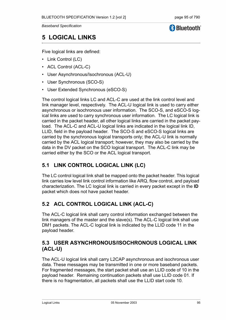
BLUETOOTH SPECIFICATION Version 1.2 [vol 2] page 95 of 790
Baseband Specification
5 LOGICAL LINKS
Five logical links are defined:
• Link Control (LC)
• ACL Control (ACL-C)
• User Asynchronous/Isochronous (ACL-U)
• User Synchronous (SCO-S)
• User Extended Synchronous (eSCO-S)
The control logical links LC and ACL-C are used at the link control level and link manager level, respectively. The ACL-U logical link is used to carry either asynchronous or isochronous user information. The SCO-S, and eSCO-S log-ical links are used to carry synchronous user information. The LC logical link is carried in the packet header, all other logical links are carried in the packet pay-load. The ACL-C and ACL-U logical links are indicated in the logical link ID, LLID, field in the payload header. The SCO-S and eSCO-S logical links are carried by the synchronous logical transports only; the ACL-U link is normally carried by the ACL logical transport; however, they may also be carried by the data in the DV packet on the SCO logical transport. The ACL-C link may be carried either by the SCO or the ACL logical transport.
5.1 LINK CONTROL LOGICAL LINK (LC)
The LC control logical link shall be mapped onto the packet header. This logical link carries low level link control information like ARQ, flow control, and payload characterization. The LC logical link is carried in every packet except in the ID packet which does not have packet header.
5.2 ACL CONTROL LOGICAL LINK (ACL-C)
The ACL-C logical link shall carry control information exchanged between the link managers of the master and the slave(s). The ACL-C logical link shall use DM1 packets. The ACL-C logical link is indicated by the LLID code 11 in the payload header.
5.3 USER ASYNCHRONOUS/ISOCHRONOUS LOGICAL LINK (ACL-U)
The ACL-U logical link shall carry L2CAP asynchronous and isochronous user data. These messages may be transmitted in one or more baseband packets. For fragmented messages, the start packet shall use an LLID code of 10 in the payload header. Remaining continuation packets shall use LLID code 01. If there is no fragmentation, all packets shall use the LLID start code 10.
Logical Links 05 November 2003 95

BLUETOOTH SPECIFICATION Version 1.2 [vol 2] page 96 of 790
Baseband Specification
5.3.1 Pausing the ACL-U logical link
When paused by LM, the Link Controller transmits the current packet with ACL-U information, if any, until an ACK is received or, optionally, until an explicit NACK is received. While the ACL-U logical link is paused, the Link Controller shall not transmit any packets with ACL-U logical link information.
If the ACL-U was paused after an ACK, the next sequence number shall be used on the next packet. If the ACL-U was paused after a NAK, the same sequence number shall be used on the next packet and the un-acknowledged packet shall be transmitted once the ACL-U logical link is un-paused.
When the ACL-U logical link is un-paused by LM, the Link Controller may resume transmitting packets with ACL-U information.
5.4 USER SYNCHRONOUS DATA LOGICAL LINK (SCO-S)
The SCO-S logical link carries transparent synchronous user data. This logical link is carried over the synchronous logical transport SCO.
5.5 USER EXTENDED SYNCHRONOUS DATA LOGICAL LINK (eSCO-S)
The eSCO-S logical link also carries transparent synchronous user data. This logical link is carried over the extended synchronous logical transport eSCO.
5.6 LOGICAL LINK PRIORITIES
The ACL-C logical link shall have a higher priority than the ACL-U logical link when scheduling traffic on the shared ACL logical transport, except in the case when retransmissions of unacknowledged ACL packets shall be given priority over traffic on the ACL-C logical link. The ACL-C logical link should also have priority over traffic on the SCO-S and eSCO-S logical links but opportunities for interleaving the logical links should be taken.
96 05 November 2003 Logical Links
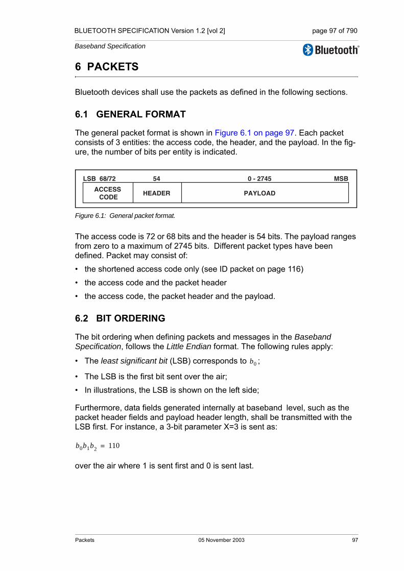
BLUETOOTH SPECIFICATION Version 1.2 [vol 2] page 97 of 790
Baseband Specification
6 PACKETS
Bluetooth devices shall use the packets as defined in the following sections.
6.1 GENERAL FORMAT
The general packet format is shown in Figure 6.1 on page 97. Each packet consists of 3 entities: the access code, the header, and the payload. In the fig-ure, the number of bits per entity is indicated.
Figure 6.1: General packet format.
The access code is 72 or 68 bits and the header is 54 bits. The payload ranges from zero to a maximum of 2745 bits. Different packet types have been defined. Packet may consist of:
• the shortened access code only (see ID packet on page 116)
• the access code and the packet header
• the access code, the packet header and the payload.
6.2 BIT ORDERING
The bit ordering when defining packets and messages in the Baseband Specification, follows the Little Endian format. The following rules apply:
• The least significant bit (LSB) corresponds to ;
• The LSB is the first bit sent over the air;
• In illustrations, the LSB is shown on the left side;
Furthermore, data fields generated internally at baseband level, such as the packet header fields and payload header length, shall be transmitted with the LSB first. For instance, a 3-bit parameter X=3 is sent as:
over the air where 1 is sent first and 0 is sent last.
ACCESS CODE
HEADER
54 0 - 274568/72
PAYLOAD
LSB MSB
b0
b0b1b2 110=
Packets 05 November 2003 97
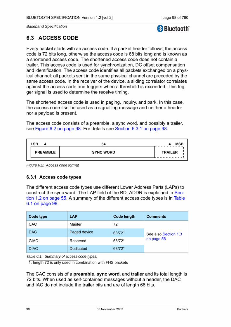
BLUETOOTH SPECIFICATION Version 1.2 [vol 2] page 98 of 790
Baseband Specification
6.3 ACCESS CODE
Every packet starts with an access code. If a packet header follows, the access code is 72 bits long, otherwise the access code is 68 bits long and is known as a shortened access code. The shortened access code does not contain a trailer. This access code is used for synchronization, DC offset compensation and identification. The access code identifies all packets exchanged on a phys-ical channel: all packets sent in the same physical channel are preceded by the same access code. In the receiver of the device, a sliding correlator correlates against the access code and triggers when a threshold is exceeded. This trig-ger signal is used to determine the receive timing.
The shortened access code is used in paging, inquiry, and park. In this case, the access code itself is used as a signalling message and neither a header nor a payload is present.
The access code consists of a preamble, a sync word, and possibly a trailer, see Figure 6.2 on page 98. For details see Section 6.3.1 on page 98.
Figure 6.2: Access code format
6.3.1 Access code types
The different access code types use different Lower Address Parts (LAPs) to construct the sync word. The LAP field of the BD_ADDR is explained in Sec-tion 1.2 on page 55. A summary of the different access code types is in Table 6.1 on page 98.
The CAC consists of a preamble, sync word, and trailer and its total length is 72 bits. When used as self-contained messages without a header, the DAC and IAC do not include the trailer bits and are of length 68 bits.
Code type LAP Code length Comments
CAC Master 72
See also Section 1.3 on page 56
DAC Paged device 68/721
1. length 72 is only used in combination with FHS packets
GIAC Reserved 68/72*
DIAC Dedicated 68/72*
Table 6.1: Summary of access code types.
PREAMBLE
644
SYNC WORD
LSB
TRAILER
4 MSB
98 05 November 2003 Packets

BLUETOOTH SPECIFICATION Version 1.2 [vol 2] page 99 of 790
Baseband Specification
6.3.2 Preamble
The preamble is a fixed zero-one pattern of 4 symbols used to facilitate DC compensation. The sequence is either 1010 or 0101, depending on whether the LSB of the following sync word is 1 or 0, respectively. The preamble is shown in Figure 6.3 on page 99.
Figure 6.3: Preamble
6.3.3 Sync word
The sync word is a 64-bit code word derived from a 24 bit address (LAP); for the CAC the master’s LAP is used; for the GIAC and the DIAC, reserved, dedi-cated LAPs are used; for the DAC, the slave LAP is used. The construction guarantees large Hamming distance between sync words based on different LAPs. In addition, the good auto correlation properties of the sync word improve timing acquisition.
6.3.3.1 Synchronization word definition
The sync words are based on a (64,30) expurgated block code with an overlay (bit-wise XOR) of a 64 bit full length pseudo-random noise (PN) sequence. The expurgated code guarantees large Hamming distance ( ) between sync words based on different addresses. The PN sequence improves the auto correlation properties of the access code. The following steps describe how the sync word shall be generated:
1. Generate information sequence;2. XOR this with the “information covering” part of the PN overlay
sequence;3. Generate the codeword;4. XOR the codeword with all 64 bits of the PN overlay sequence;
The information sequence is generated by appending 6 bits to the 24 bit LAP (step 1). The appended bits are if the MSB of the LAP equals 0. If the MSB of the LAP is 1 the appended bits are . The LAP MSB together with the appended bits constitute a length-seven Barker sequence. The purpose of including a Barker sequence is to further improve the auto correlation proper-ties. In step 2 the information is pre-scrambled by XORing it with the bits
of the PN sequence (defined in section 6.3.3.2 on page 102). After generating the codeword (step 3), the complete PN sequence is XORed to the
preamble sync word
0 1 0 1 0
LSB LSB LSBMSB LSB MSB
preamble sync word
1 0 1 0 1
dmin 14=
001101110010
p34…p63
Packets 05 November 2003 99
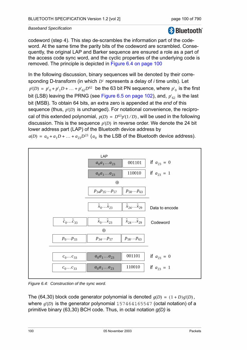
BLUETOOTH SPECIFICATION Version 1.2 [vol 2] page 100 of 790
Baseband Specification
codeword (step 4). This step de-scrambles the information part of the code-word. At the same time the parity bits of the codeword are scrambled. Conse-quently, the original LAP and Barker sequence are ensured a role as a part of the access code sync word, and the cyclic properties of the underlying code is removed. The principle is depicted in Figure 6.4 on page 100
In the following discussion, binary sequences will be denoted by their corre-sponding D-transform (in which represents a delay of i time units). Let
be the 63 bit PN sequence, where is the first bit (LSB) leaving the PRNG (see Figure 6.5 on page 102), and, is the last bit (MSB). To obtain 64 bits, an extra zero is appended at the end of this sequence (thus, is unchanged). For notational convenience, the recipro-cal of this extended polynomial, , will be used in the following discussion. This is the sequence in reverse order. We denote the 24 bit lower address part (LAP) of the Bluetooth device address by
( is the LSB of the Bluetooth device address).
Figure 6.4: Construction of the sync word.
The (64,30) block code generator polynomial is denoted , where is the generator polynomial 157464165547 (octal notation) of a primitive binary (63,30) BCH code. Thus, in octal notation g(D) is
Di
p' D( ) p'0 p'1D … p'62D62+ + += p'0p'62
p' D( )p D( ) D63p' 1 D⁄( )=
p' D( )
a D( ) a0 a1D … a23D23+ + += a0
a0a1…a23 001101LAP
a0a1…a23 110010
if a23 0=
if a23 1=
p34p35…p57 p58…p63
⊕
x0…x23 x24…x29 Data to encode
x0…x23 x24…x29c0…c33 Codeword
p34…p57 p58…p63p0…p33
⊕
a0a1…a23 001101c0…c33 if a23 0=
a0a1…a23 110010c0…c33 if a23 1=
g D( ) 1 D+( )g' D( )=
g' D( )
100 05 November 2003 Packets

BLUETOOTH SPECIFICATION Version 1.2 [vol 2] page 101 of 790
Baseband Specification
(EQ 8)
the left-most bit corresponds to the high-order ( ) coefficient.The DC-free four bit sequences 0101 and 1010 can be written
(EQ 9)
respectively. Furthermore,
(EQ 10)
which are used to create the length seven Barker sequences. Then, the access code shall be generated by the following procedure:
1. Format the 30 information bits to encode:
2. Add the information covering part of the PN overlay sequence:
3. Generate parity bits of the (64,30) expurgated block code:1
4. Create the codeword:
5. Add the PN sequence:
6. Append the (DC-free) preamble and trailer:
1. x(D) mod y(D) denotes the remainder when x(D) is divided by y(D).
g D( ) 260534236651,=
g34
F0 D( ) D D3,+=
F1 D( ) 1 D2,+=⎩⎪⎨⎪⎧
B0 D( ) D2 D3 D5,+ +=
B1 D( ) 1 D D4,+ +=⎩⎪⎨⎪⎧
x D( ) a D( ) D24Ba23D( ).+=
x D( ) x D( ) p34 p35D … p63D29.+ + + +=
c D( ) D34x D( ) mod g D( )= .
s D( ) D34x D( ) c D( ).+=
s D( ) s D( ) p D( ).+=
y D( ) Fc0D( ) D4s D( ) D68Fa23
D( ).+ +=
Packets 05 November 2003 101
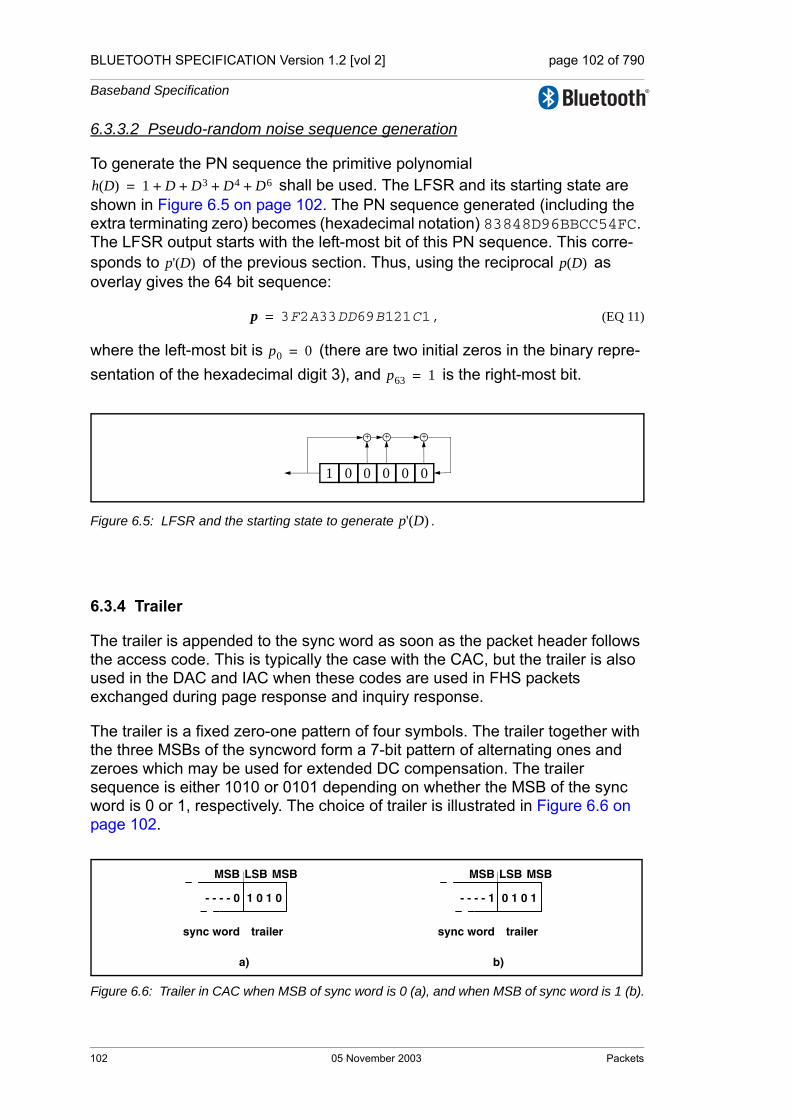
BLUETOOTH SPECIFICATION Version 1.2 [vol 2] page 102 of 790
Baseband Specification
6.3.3.2 Pseudo-random noise sequence generation
To generate the PN sequence the primitive polynomial shall be used. The LFSR and its starting state are
shown in Figure 6.5 on page 102. The PN sequence generated (including the extra terminating zero) becomes (hexadecimal notation) 83848D96BBCC54FC. The LFSR output starts with the left-most bit of this PN sequence. This corre-sponds to of the previous section. Thus, using the reciprocal as overlay gives the 64 bit sequence:
(EQ 11)
where the left-most bit is (there are two initial zeros in the binary repre-sentation of the hexadecimal digit 3), and is the right-most bit.
Figure 6.5: LFSR and the starting state to generate .
6.3.4 Trailer
The trailer is appended to the sync word as soon as the packet header follows the access code. This is typically the case with the CAC, but the trailer is also used in the DAC and IAC when these codes are used in FHS packets exchanged during page response and inquiry response.
The trailer is a fixed zero-one pattern of four symbols. The trailer together with the three MSBs of the syncword form a 7-bit pattern of alternating ones and zeroes which may be used for extended DC compensation. The trailer sequence is either 1010 or 0101 depending on whether the MSB of the sync word is 0 or 1, respectively. The choice of trailer is illustrated in Figure 6.6 on page 102.
Figure 6.6: Trailer in CAC when MSB of sync word is 0 (a), and when MSB of sync word is 1 (b).
h D( ) 1 D D3 D4 D6+ + + +=
p' D( ) p D( )
p 3F2A33DD69B121C1,=
p0 0=
p63 1=
+
1 0 0 0 0 0
+ +
p' D( )
sync word trailer
b)a)
0 1 0 1- - - - 1
MSB MSBLSB MSB LSB MSB
sync word trailer
1 0 1 0- - - - 0
102 05 November 2003 Packets

BLUETOOTH SPECIFICATION Version 1.2 [vol 2] page 103 of 790
Baseband Specification
6.4 PACKET HEADERThe header contains link control (LC) information and consists of 6 fields:
• LT_ADDR: 3- bit logical transport address • TYPE: 4-bit type code • FLOW: 1-bit flow control • ARQN: 1-bit acknowledge indication • SEQN: 1-bit sequence number • HEC: 8-bit header error check
The total header, including the HEC, consists of 18 bits, see Figure 6.7 on page 103, and is encoded with a rate 1/3 FEC (not shown but described in Section 7.4 on page 122) resulting in a 54-bit header. The LT_ADDR and TYPE fields shall be sent LSB first.
Figure 6.7: Header format.
6.4.1 LT_ADDR
The 3-bit LT_ADDR field contains the logical transport address for the packet (see Section 4.2 on page 85). This field indicates the destination slave for a packet in a master-to-slave transmission slot and indicates the source slave for a slave-to-master transmission slot.
6.4.2 TYPE
Sixteen different types of packets can be distinguished. The 4-bit TYPE code specifies which packet type is used. The interpretation of the TYPE code depends on the logical transport address in the packet. First, it shall be deter-mined whether the packet is sent on an SCO logical transport, an eSCO logical transport, or an ACL logical transport. Then it can be determined which type of SCO packet, eSCO packet, or ACL packet has been received. The TYPE code determines how many slots the current packet will occupy (see the slot occu-pancy column in Table 6.2 on page 105). This allows the non-addressed receivers to refrain from listening to the channel for the duration of the remain-ing slots. In Section 6.5 on page 105, each packet type is described in more detail.
4
TYPE
1
SEQN
8
HEC
3
LT_ADDR
1
FLOW
1
ARQN
MSBLSB
Packets 05 November 2003 103

BLUETOOTH SPECIFICATION Version 1.2 [vol 2] page 104 of 790
Baseband Specification
6.4.3 FLOW
The FLOW bit is used for flow control of packets over the ACL logical transport. When the RX buffer for the ACL logical transport in the recipient is full, a STOP indication (FLOW=0) shall be returned to stop the other device from transmit-ting data temporarily. The STOP signal only affects ACL packets. Packets including only link control information (ID, POLL, and NULL packets), SCO packets or eSCO packets can still be received. When the RX buffer can accept data, a GO indication (FLOW=1) shall be returned. When no packet is received, or the received header is in error, a GO shall be assumed implicitly. In this case, the slave can receive a new packet with CRC although its RX buffer is still not emptied. The slave shall then return a NAK in response to this packet even if the packet passed the CRC check.
The FLOW bit is not used on the eSCO logical transport or the ACL-C logical link and shall be set to one on transmission and ignored upon receipt.
6.4.4 ARQN
The 1-bit acknowledgment indication ARQN is used to inform the source of a successful transfer of payload data with CRC, and can be positive acknowl-edge ACK or negative acknowledge NAK. See Section 7.6 on page 124 for ini-tialization and usage of this bit.
6.4.5 SEQN
The SEQN bit provides a sequential numbering scheme to order the data packet stream. See section 7.6.2 on page 127 for initialization and usage of the SEQN bit. For broadcast packets, a modified sequencing method is used, see Section 7.6.5 on page 130.
6.4.6 HEC
Each header has a header-error-check to check the header integrity. The HEC is an 8-bit word (generation of the HEC is specified in Section 7.1.1 on page 118). Before generating the HEC, the HEC generator is initialized with an 8-bit value. For FHS packets sent in master response substate, the slave upper address part (UAP) shall be used. For FHS packets sent in inquiry response, the default check initialization (DCI, see Section 1.2.1 on page 55) shall be used. In all other cases, the UAP of the master device shall be used.
After the initialization, a HEC shall be calculated for the 10 header bits. Before checking the HEC, the receiver shall initialize the HEC check circuitry with the proper 8-bit UAP (or DCI). If the HEC does not check, the entire packet shall be discarded. More information can be found in Section 7.1 on page 118.
104 05 November 2003 Packets
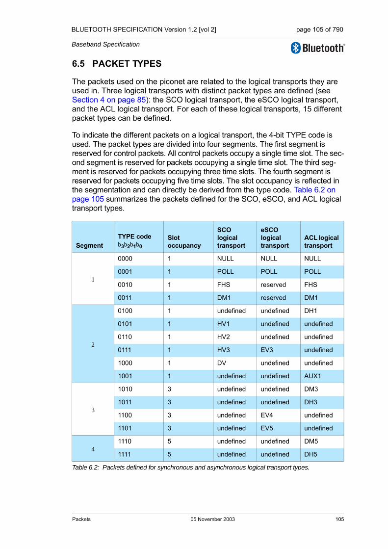
BLUETOOTH SPECIFICATION Version 1.2 [vol 2] page 105 of 790
Baseband Specification
6.5 PACKET TYPES
The packets used on the piconet are related to the logical transports they are used in. Three logical transports with distinct packet types are defined (see Section 4 on page 85): the SCO logical transport, the eSCO logical transport, and the ACL logical transport. For each of these logical transports, 15 different packet types can be defined.
To indicate the different packets on a logical transport, the 4-bit TYPE code is used. The packet types are divided into four segments. The first segment is reserved for control packets. All control packets occupy a single time slot. The sec-ond segment is reserved for packets occupying a single time slot. The third seg-ment is reserved for packets occupying three time slots. The fourth segment is reserved for packets occupying five time slots. The slot occupancy is reflected in the segmentation and can directly be derived from the type code. Table 6.2 on page 105 summarizes the packets defined for the SCO, eSCO, and ACL logical transport types.
SegmentTYPE codeb3b2b1b0
Slot occupancy
SCO logical transport
eSCO logical transport
ACL logical transport
1
0000 1 NULL NULL NULL
0001 1 POLL POLL POLL
0010 1 FHS reserved FHS
0011 1 DM1 reserved DM1
2
0100 1 undefined undefined DH1
0101 1 HV1 undefined undefined
0110 1 HV2 undefined undefined
0111 1 HV3 EV3 undefined
1000 1 DV undefined undefined
1001 1 undefined undefined AUX1
3
1010 3 undefined undefined DM3
1011 3 undefined undefined DH3
1100 3 undefined EV4 undefined
1101 3 undefined EV5 undefined
41110 5 undefined undefined DM5
1111 5 undefined undefined DH5
Table 6.2: Packets defined for synchronous and asynchronous logical transport types.
Packets 05 November 2003 105
BLUETOOTH SPECIFICATION Version 1.2 [vol 2] page 106 of 790
Baseband Specification
6.5.1 Common packet types
There are five common kinds of packets. In addition to the types listed in seg-ment 1 of the previous table, the ID packet is also a common packet type but is not listed in segment 1 because it does not have a packet header.
6.5.1.1 ID packet
The identity or ID packet consists of the device access code (DAC) or inquiry access code (IAC). It has a fixed length of 68 bits. It is a very robust packet since the receiver uses a bit correlator to match the received packet to the known bit sequence of the ID packet.
6.5.1.2 NULL packet
The NULL packet has no payload and consists of the channel access code and packet header only. Its total (fixed) length is 126 bits. The NULL packet may be used to return link information to the source regarding the success of the previ-ous transmission (ARQN), or the status of the RX buffer (FLOW). The NULL packet may not have to be acknowledged.
6.5.1.3 POLL packet
The POLL packet is very similar to the NULL packet. It does not have a pay-load. In contrast to the NULL packet, it requires a confirmation from the recipi-ent. It is not a part of the ARQ scheme. The POLL packet does not affect the ARQN and SEQN fields. Upon reception of a POLL packet the slave shall respond with a packet even when the slave does not have any information to send unless the slave has scatternet commitments in that timeslot. This return packet is an implicit acknowledgement of the POLL packet. This packet can be used by the master in a piconet to poll the slaves. Slaves shall not transmit the POLL packet.
6.5.1.4 FHS packet
The FHS packet is a special control packet containing, among other things, the Bluetooth device address and the clock of the sender. The payload contains 144 information bits plus a 16-bit CRC code. The payload is coded with a rate 2/3 FEC with a gross payload length of 240 bits.
Figure 6.8 on page 107 illustrates the format and contents of the FHS payload. The payload consists of eleven fields. The FHS packet is used in page master response, inquiry response and in role switch.
The FHS packet contains real-time clock information. This clock information shall be updated before each retransmission. The retransmission of the FHS payload is different than retransmissions of ordinary data payloads where the same payload is used for each retransmission. The FHS packet is used for fre-
106 05 November 2003 Packets

BLUETOOTH SPECIFICATION Version 1.2 [vol 2] page 107 of 790
Baseband Specification
quency hop synchronization before the piconet channel has been established, or when an existing piconet changes to a new piconet.
Figure 6.8: Format of the FHS payload.
Each field is described in more detail below:
Parity bitsThis 34-bit field contains the parity bits that form the first part of the sync word of the access code of the device that sends the FHS packet. These bits are derived from the LAP as described in Section 1.2 on page 55.
LAPThis 24-bit field shall contain the lower address part of the device that sends the FHS packet.
Undefined This 2-bit field is reserved for future use and shall be set to zero.
SRThis 2-bit field is the scan repetition field and indicates the interval between two consecutive page scan windows, see also Table 6.4 and Table 8.1 on page 135
Reserved This 2-bit field shall be set to 10.
UAPThis 8-bit field shall contain the upper address part of the device that sends the FHS packet.
NAPThis 16-bit field shall contain the non-significant address part of the device that sends the FHS packet (see also Section 1.2 on page 55 for LAP, UAP, and NAP).
Class of device
This 24-bit field shall contain the class of device of the device that sends the FHS packet. The field is defined in Bluetooth Assigned Numbers (https://www.bluetooth.org/foundry/assignnumb/document/assigned_numbers).
LT_ADDR
This 3-bit field shall contain the logical transport address the recipient shall use if the FHS packet is used at connection setup or role switch. A slave responding to a master or a device responding to an inquiry request mes-sage shall include an all-zero LT_ADDR field if it sends the FHS packet.
CLK27-2
This 26-bit field shall contain the value of the native clock of the device that sends the FHS packet, sampled at the beginning of the transmission of the access code of this FHS packet. This clock value has a resolution of 1.25ms (two-slot interval). For each new transmission, this field is updated so that it accurately reflects the real-time clock value.
Page scan mode
This 3-bit field shall indicate which scan mode is used by default by the sender of the FHS packet. The interpretation of the page scan mode is illus-trated in Table 6.5.
Table 6.3: Description of the FHS payload
Parity bits LAPUn-
definedSR UAP NAP
LSB MSB
Class of device
LT_ ADDR
CLK27-2
Page scan mode
34 24 2 2 2 8 16 24 3 26 3
Res
erve
d
Packets 05 November 2003 107

BLUETOOTH SPECIFICATION Version 1.2 [vol 2] page 108 of 790
Baseband Specification
The device sending the FHS shall set the SR bits according to Table 6.4.
The device sending the FHS shall set the page scan mode bits according to Table 6.5.
The LAP, UAP, and NAP together form the 48-bit Bluetooth Device Address of the device that sends the FHS packet. Using the parity bits and the LAP, the recipient can directly construct the channel access code of the sender of the FHS packet.
When initializing the HEC and CRC for the FHS packet of inquiry response, the UAP shall be the DCI.
6.5.1.5 DM1 packet
DM1 is part of segment 1 in order to support control messages in any logical transport that allows the DM1 packet (see Table 6.2 on page 105). However, it may also carry regular user data. Since the DM1 packet can be regarded as an ACL packet, it will be discussed in Section 6.5.4 on page 111.
SR bit format b1b0 SR mode
00 R0
01 R1
10 R2
11 reserved
Table 6.4: Contents of SR field
Bit format b2b1b0 Page scan mode
000 Mandatory scan mode
001 Reserved for future use
010 Reserved for future use
011 Reserved for future use
100 Reserved for future use
101 Reserved for future use
110 Reserved for future use
111 Reserved for future use
Table 6.5: Contents of page scan mode field
108 05 November 2003 Packets
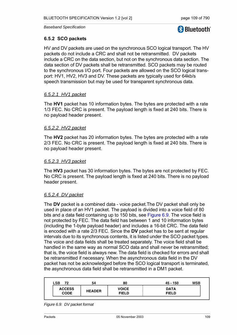
BLUETOOTH SPECIFICATION Version 1.2 [vol 2] page 109 of 790
Baseband Specification
6.5.2 SCO packets
HV and DV packets are used on the synchronous SCO logical transport. The HV packets do not include a CRC and shall not be retransmitted. DV packets include a CRC on the data section, but not on the synchronous data section. The data section of DV packets shall be retransmitted. SCO packets may be routed to the synchronous I/O port. Four packets are allowed on the SCO logical trans-port: HV1, HV2, HV3 and DV. These packets are typically used for 64kb/s speech transmission but may be used for transparent synchronous data.
6.5.2.1 HV1 packet
The HV1 packet has 10 information bytes. The bytes are protected with a rate 1/3 FEC. No CRC is present. The payload length is fixed at 240 bits. There is no payload header present.
6.5.2.2 HV2 packet
The HV2 packet has 20 information bytes. The bytes are protected with a rate 2/3 FEC. No CRC is present. The payload length is fixed at 240 bits. There is no payload header present.
6.5.2.3 HV3 packet
The HV3 packet has 30 information bytes. The bytes are not protected by FEC. No CRC is present. The payload length is fixed at 240 bits. There is no payload header present.
6.5.2.4 DV packet
The DV packet is a combined data - voice packet.The DV packet shall only be used in place of an HV1 packet. The payload is divided into a voice field of 80 bits and a data field containing up to 150 bits, see Figure 6.9. The voice field is not protected by FEC. The data field has between 1 and 10 information bytes (including the 1-byte payload header) and includes a 16-bit CRC. The data field is encoded with a rate 2/3 FEC. Since the DV packet has to be sent at regular intervals due to its synchronous contents, it is listed under the SCO packet types. The voice and data fields shall be treated separately. The voice field shall be handled in the same way as normal SCO data and shall never be retransmitted; that is, the voice field is always new. The data field is checked for errors and shall be retransmitted if necessary. When the asynchronous data field in the DV packet has not be acknowledged before the SCO logical transport is terminated, the asynchronous data field shall be retransmitted in a DM1 packet.
Figure 6.9: DV packet format
ACCESS CODE
VOICE FIELD
HEADER
54 80 45 - 15072
DATAFIELD
LSB MSB
Packets 05 November 2003 109
BLUETOOTH SPECIFICATION Version 1.2 [vol 2] page 110 of 790
Baseband Specification
6.5.3 eSCO packets
EV packets are used on the synchronous eSCO logical transport. The packets include a CRC and retransmission may be applied if no acknowledgement of proper reception is received within the retransmission window. eSCO packets may be routed to the synchronous I/O port. Three eSCO packets have been defined. The eSCO packets may be used for 64kb/s speech transmission as well as transparent data at 64kb/s and other rates.
6.5.3.1 EV3 packet
The EV3 packet has between 1 and 30 information bytes plus a 16-bit CRC code. The bytes are not protected by FEC. The EV3 packet may cover up to a single time slot. There is no payload header present. The payload length is set during the LMP eSCO setup and remains fixed until the link is removed or re-negotiated.
6.5.3.2 EV4 packet
The EV4 packet has between 1 and 120 information bytes plus a 16-bit CRC code. The EV4 packet may cover to up three time slots. The information plus CRC bits are coded with a rate 2/3 FEC. There is no payload header present. The payload length is set during the LMP eSCO setup and remains fixed until the link is removed or re-negotiated.
6.5.3.3 EV5 packet
The EV5 packet has between 1 and 180 information bytes plus a 16-bit CRC code. The bytes are not protected by FEC. The EV5 packet may cover up to three time slots. There is no payload header present. The payload length is set during the LMP eSCO setup and remains fixed until the link is removed or re-negotiated.
110 05 November 2003 Packets

BLUETOOTH SPECIFICATION Version 1.2 [vol 2] page 111 of 790
Baseband Specification
6.5.4 ACL packets
ACL packets are used on the asynchronous logical transport. The information carried may be user data or control data.
6.5.4.1 DM1 packet
The DM1 packet carries data information only. The payload has between 1 and 18 information bytes (including the 1-byte payload header) plus a 16-bit CRC code. The DM1 packet occupies a single time slot. The information plus CRC bits are coded with a rate 2/3 FEC. The payload header in the DM1 packet is 1 byte long, see Figure 6.10 on page 113. The length indicator in the payload header specifies the number of user bytes (excluding payload header and the CRC code).
6.5.4.2 DH1 packet
This packet is similar to the DM1 packet, except that the information in the pay-load is not FEC encoded. As a result, the DH1 packet has between 1 and 28 information bytes (including the 1-byte payload header) plus a 16-bit CRC code. The DH1 packet occupies a single time slot.
6.5.4.3 DM3 packet
The DM3 packet may occupy up to three time slots. The payload has between 2 and 123 information bytes (including the 2-byte payload header) plus a 16-bit CRC code. The information plus CRC bits are coded with a rate 2/3 FEC. The payload header in the DM3 packet is 2 bytes long, see Figure 6.11 on page 113. The length indicator in the payload header specifies the number of user bytes (excluding payload header and the CRC code).
6.5.4.4 DH3 packet
This packet is similar to the DM3 packet, except that the information in the pay-load is not FEC encoded. As a result, the DH3 packet has between 2 and 185 information bytes (including the 2-byte payload header) plus a 16-bit CRC code. The DH3 packet may occupy up to three time slots.
6.5.4.5 DM5 packet
The DM5 packet may occupy up to five time slots. The payload has between 2 and 226 information bytes (including the 2-byte payload header) plus a 16-bit CRC code. The payload header in the DM5 packet is 2 bytes long. The infor-mation plus CRC bits are coded with a rate 2/3 FEC. The length indicator in the payload header specifies the number of user bytes (excluding payload header and the CRC code).
Packets 05 November 2003 111
BLUETOOTH SPECIFICATION Version 1.2 [vol 2] page 112 of 790
Baseband Specification
6.5.4.6 DH5 packet
This packet is similar to the DM5 packet, except that the information in the pay-load is not FEC encoded. As a result, the DH5 packet has between 2 and 341 information bytes (including the2-byte payload header) plus a 16-bit CRC code. The DH5 packet may occupy up to five time slots.
6.5.4.7 AUX1 packet
This packet resembles a DH1 packet but has no CRC code. The AUX1 packet has between 1 and 30 information bytes (including the 1-byte payload header). The AUX1 packet occupies a single time slot. The AUX1 packet shall not be used for the ACL-U or ACL-C logical links. An AUX1 packet may be discarded.
6.6 PAYLOAD FORMAT
In the payload, two fields are distinguished: the synchronous data field and the asynchronous data field. The ACL packets only have the asynchronous data field and the SCO and eSCOpackets only have the synchronous data field − with the exception of the DV packets which have both.
6.6.1 Synchronous data field
In SCO, the synchronous data field has a fixed length and consists only of the synchronous data body portion. No payload header is present.
In eSCO, the synchronous data field consists of two segments: a synchronous data body and a CRC code. No payload header is present.
1. Synchronous data bodyFor HV and DV packets, the synchronous data body length is fixed. For EV packets, the synchronous data body length is negotiated during the LMP eSCO setup. Once negotiated, the synchronous data body length remains constant unless re-negotiated. The synchronous data body length may be different for each direction of the eSCO logical transport.
2. CRC codeThe 16-bit CRC in the payload is generated as specified in Section 7.1 on page 118. The 8-bit UAP of the master is used to initialize the CRC generator.
112 05 November 2003 Packets
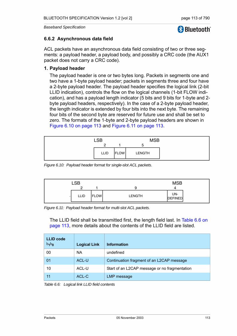
BLUETOOTH SPECIFICATION Version 1.2 [vol 2] page 113 of 790
Baseband Specification
6.6.2 Asynchronous data field
ACL packets have an asynchronous data field consisting of two or three seg-ments: a payload header, a payload body, and possibly a CRC code (the AUX1 packet does not carry a CRC code).
1. Payload headerThe payload header is one or two bytes long. Packets in segments one and two have a 1-byte payload header; packets in segments three and four have a 2-byte payload header. The payload header specifies the logical link (2-bit LLID indication), controls the flow on the logical channels (1-bit FLOW indi-cation), and has a payload length indicator (5 bits and 9 bits for 1-byte and 2-byte payload headers, respectively). In the case of a 2-byte payload header, the length indicator is extended by four bits into the next byte. The remaining four bits of the second byte are reserved for future use and shall be set to zero. The formats of the 1-byte and 2-byte payload headers are shown in Figure 6.10 on page 113 and Figure 6.11 on page 113.
Figure 6.10: Payload header format for single-slot ACL packets.
Figure 6.11: Payload header format for multi-slot ACL packets.
The LLID field shall be transmitted first, the length field last. In Table 6.6 on page 113, more details about the contents of the LLID field are listed.
LLID code b1b0 Logical Link Information
00 NA undefined
01 ACL-U Continuation fragment of an L2CAP message
10 ACL-U Start of an L2CAP message or no fragmentation
11 ACL-C LMP message
Table 6.6: Logical link LLID field contents
LLID FLOW
1LSB
2
LENGTH
5MSB
LLID FLOW
1
LENGTH UN-DEFINED
LSB MSB9 42
Packets 05 November 2003 113
BLUETOOTH SPECIFICATION Version 1.2 [vol 2] page 114 of 790
Baseband Specification
An L2CAP message may be fragmented into several packets. Code 10 shall be used for an ACL-U packet carrying the first fragment of such a message; code 01 shall be used for continuing fragments. If there is no fragmentation, code 10 shall be used for every packet. Code 11 shall be used for LMP mes-sages. Code 00 is reserved for future use.The flow indicator in the payload is used to control the flow at the L2CAP level. It is used to control the flow per logical link. FLOW=1 means flow-on (GO) and FLOW=0 means flow-off (STOP). After a new connection has been established the flow indicator shall be set to GO. When a device receives a payload header with the flow bit set to STOP, it shall stop the transmission of ACL packets before an additional amount of payload data is sent. This amount is defined as the flow control lag, expressed as a number of bytes. The shorter the flow control lag, the less buffering the other device must dedicate to this function. The flow control lag shall not exceed 1792 bytes (7 × 256 bytes). In order to allow devices to optimize the selection of packet length and buffer space, the flow control lag of a given implementa-tion shall be provided in the LMP_features_res message. If a packet containing the payload flow bit of STOP is received, with a valid packet header but bad payload, the payload flow control bit shall be ignored. The baseband ACK contained in the packet header will be received and a further ACL packet may be transmitted. Each occurrence of this situation allows a further ACL packet to be sent in spite of the flow control request being sent via the payload header flow control bit. It is recommended that devices that use the payload header flow bit should ensure that no further ACL packets are sent until the payload flow bit has been correctly received. This can be accomplished by simultaneously turning on the flow bit in the packet header and keeping it on until an ACK is received back (ARQN=1). This will typically be only one round trip time. Since they lack a payload CRC, AUX1 packets should not be used with a payload flow bit of STOP.
114 05 November 2003 Packets
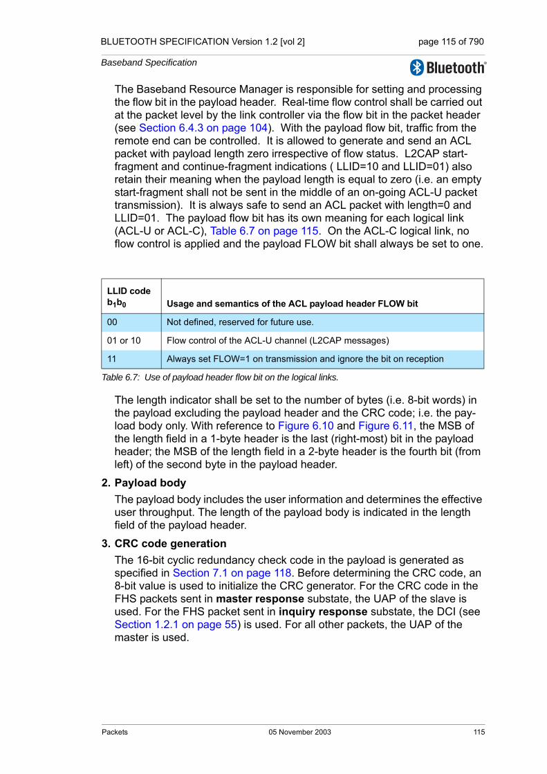
BLUETOOTH SPECIFICATION Version 1.2 [vol 2] page 115 of 790
Baseband Specification
The Baseband Resource Manager is responsible for setting and processing the flow bit in the payload header. Real-time flow control shall be carried out at the packet level by the link controller via the flow bit in the packet header (see Section 6.4.3 on page 104). With the payload flow bit, traffic from the remote end can be controlled. It is allowed to generate and send an ACL packet with payload length zero irrespective of flow status. L2CAP start-fragment and continue-fragment indications ( LLID=10 and LLID=01) also retain their meaning when the payload length is equal to zero (i.e. an empty start-fragment shall not be sent in the middle of an on-going ACL-U packet transmission). It is always safe to send an ACL packet with length=0 and LLID=01. The payload flow bit has its own meaning for each logical link (ACL-U or ACL-C), Table 6.7 on page 115. On the ACL-C logical link, no flow control is applied and the payload FLOW bit shall always be set to one.
The length indicator shall be set to the number of bytes (i.e. 8-bit words) in the payload excluding the payload header and the CRC code; i.e. the pay-load body only. With reference to Figure 6.10 and Figure 6.11, the MSB of the length field in a 1-byte header is the last (right-most) bit in the payload header; the MSB of the length field in a 2-byte header is the fourth bit (from left) of the second byte in the payload header.
2. Payload bodyThe payload body includes the user information and determines the effective user throughput. The length of the payload body is indicated in the length field of the payload header.
3. CRC code generationThe 16-bit cyclic redundancy check code in the payload is generated as specified in Section 7.1 on page 118. Before determining the CRC code, an 8-bit value is used to initialize the CRC generator. For the CRC code in the FHS packets sent in master response substate, the UAP of the slave is used. For the FHS packet sent in inquiry response substate, the DCI (see Section 1.2.1 on page 55) is used. For all other packets, the UAP of the master is used.
LLID codeb1b0 Usage and semantics of the ACL payload header FLOW bit
00 Not defined, reserved for future use.
01 or 10 Flow control of the ACL-U channel (L2CAP messages)
11 Always set FLOW=1 on transmission and ignore the bit on reception
Table 6.7: Use of payload header flow bit on the logical links.
Packets 05 November 2003 115

BLUETOOTH SPECIFICATION Version 1.2 [vol 2] page 116 of 790
Baseband Specification
6.7 PACKET SUMMARYA summary of the packets and their characteristics is shown in Table 6.8, Table 6.9 and Table 6.10. The payload represents the packet payload exclud-ing FEC, CRC, and payload header.
Type Payload (bytes) FEC CRC Symmetric Max. Rate
Asymmetric Max. Rate
ID na na na na na
NULL na na na na na
POLL na na na na na
FHS 18 2/3 yes na na
Table 6.8: Link control packets
Type
Payload Header(bytes)
Payload (bytes) FEC CRC
SymmetricMax. Rate (kb/s)
Asymmetric Max. Rate (kb/s)
Forward Reverse
DM1 1 0-17 2/3 yes 108.8 108.8 108.8
DH1 1 0-27 no yes 172.8 172.8 172.8
DM3 2 0-121 2/3 yes 258.1 387.2 54.4
DH3 2 0-183 no yes 390.4 585.6 86.4
DM5 2 0-224 2/3 yes 286.7 477.8 36.3
DH5 2 0-339 no yes 433.9 723.2 57.6
AUX1 1 0-29 no no 185.6 185.6 185.6
Table 6.9: ACL packets
TypePayload Header (bytes) Payload (bytes) FEC CRC
Symmetric Max. Rate (kb/s)
HV1 na 10 1/3 no 64.0
HV2 na 20 2/3 no 64.0
HV3 na 30 no no 64.0
DV1
1. Items followed by ‘D’ relate to data field only.
1 D 10+(0-9) D 2/3 D yes D 64.0+57.6 D
EV3 na 1-30 No Yes 96
EV4 na 1-120 2/3 Yes 192
EV5 na 1-180 No Yes 288
Table 6.10: Synchronous packets
116 05 November 2003 Packets

BLUETOOTH SPECIFICATION Version 1.2 [vol 2] page 117 of 790
Baseband Specification
7 BITSTREAM PROCESSING
Bluetooth devices shall use the bitstream processing schemes as defined in the following sections.
Before the payload is sent over the air interface, several bit manipulations are performed in the transmitter to increase reliability and security. An HEC is added to the packet header, the header bits are scrambled with a whitening word, and FEC coding is applied. In the receiver, the inverse processes are carried out. Figure 7.1 on page 117 shows the processes carried out for the packet header both at the transmit and the receive side. All header bit pro-cesses are mandatory.
Figure 7.1: Header bit processes.
Figure 7.2 on page 117 shows the processes that may be carried out on the payload. In addition to the processes defined for the packet header, encryption can be applied on the payload. Only whitening and de-whitening, as explained in Section 7.2 on page 121, are mandatory for every payload; all other pro-cesses are optional and depend on the packet type (see Section 6.6 on page 112) and whether encryption is enabled. In Figure 7.2 on page 117, optional processes are indicated by dashed blocks.
Figure 7.2: Payload bit processes.
HEC checking
HEC generation
RX header
TX header
RF interface
FEC encoding
decodingde-whitening
whitening(LSB first)
encoding
decodingde-whitening
whiteningTX payload
RX payload
CRC generation
CRC checking
encryption
decryption
RF interface
(LSB first)
Bitstream Processing 05 November 2003 117

BLUETOOTH SPECIFICATION Version 1.2 [vol 2] page 118 of 790
Baseband Specification
7.1 ERROR CHECKING
The packet can be checked for errors or wrong delivery using the channel access code, the HEC in the header, and the CRC in the payload. At packet reception, the access code is checked first. Since the 64-bit sync word in the channel access code is derived from the 24-bit master LAP, this checks if the LAP is correct, and prevents the receiver from accepting a packet of another piconet (provided the LAP field of the master's BD_ADDR is different).
The HEC and CRC computations are normally initialized with the UAP of the master. Even though the access code may be the same for two piconets the different UAP values will typically cause the HEC and CRC to fail. However, there is an exception where no common UAP is available in the transmitter and receiver. This is the case when the HEC and CRC are generated for the FHS packet in inquiry response substate. In this case the DCI value shall be used.
The generation and check of the HEC and CRC are summarized in Figure 7.5 on page 119 and Figure 7.8 on page 120. Before calculating the HEC or CRC, the shift registers in the HEC/CRC generators shall be initialized with the 8-bit UAP (or DCI) value. Then the header and payload information shall be shifted into the HEC and CRC generators, respectively (with the LSB first).
7.1.1 HEC generation
The HEC generating LFSR is depicted in Figure 7.3 on page 118. The genera-tor polynomial is
. Initially this cir-cuit shall be pre-loaded with the 8-bit UAP such that the LSB of the UAP (denoted UAP0) goes to the left-most shift register element, and, UAP7 goes to the right-most element. The initial state of the HEC LFSR is depicted in Figure 7.4 on page 119. Then the data shall be shifted in with the switch S set in posi-tion 1. When the last data bit has been clocked into the LFSR, the switch S shall be set in position 2, and, the HEC can be read out from the register. The LFSR bits shall be read out from right to left (i.e., the bit in position 7 is the first to be transmitted, followed by the bit in position 6, etc.).
Figure 7.3: The LFSR circuit generating the HEC.
g D( ) D 1+( ) D7 D4 D3 D2 1+ + + +( ) D8 D7 D5 D2 D 1+ + + + += =
Data in (LSB first)
D8D7D5D2D0 D1 S1
2
Position 0 1 2 3 4 65 7
118 05 November 2003 Bitstream Processing
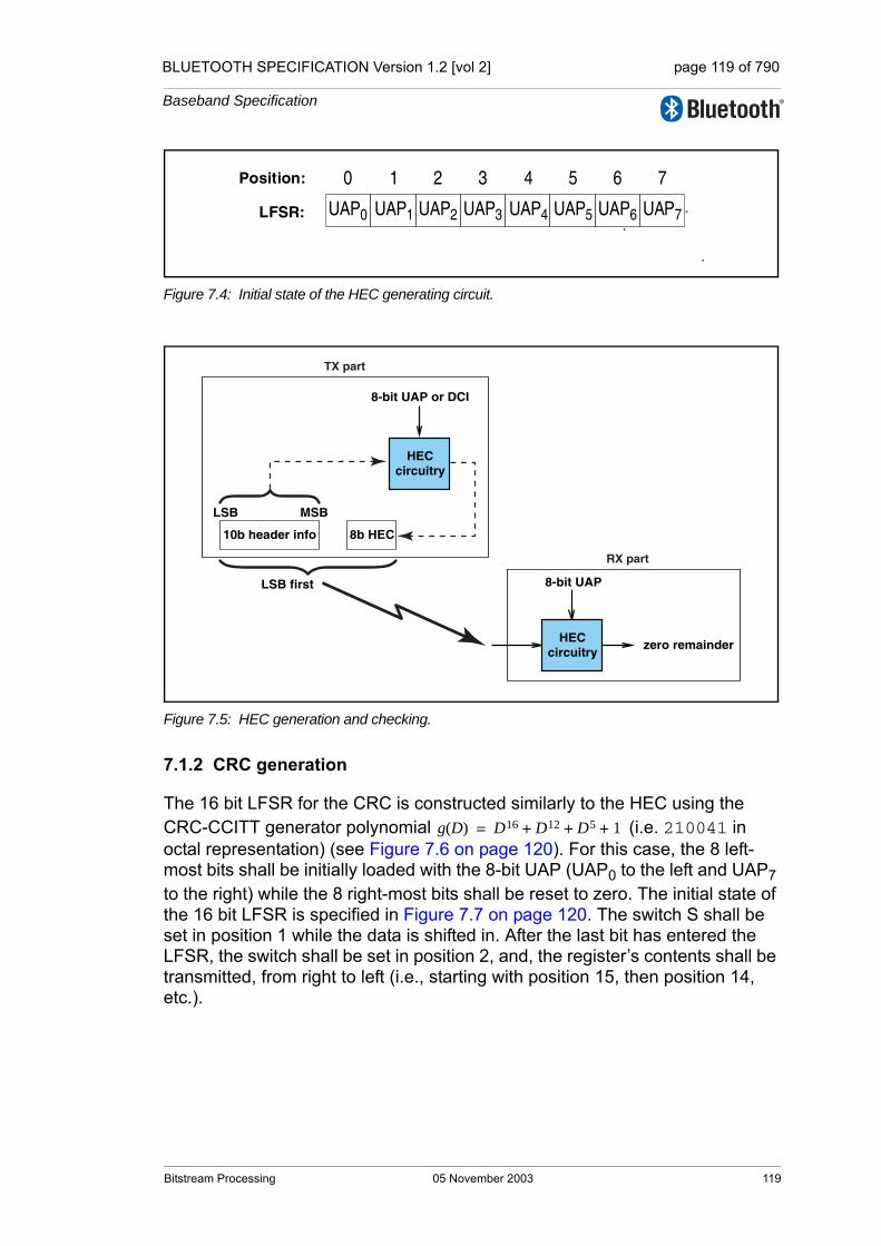
BLUETOOTH SPECIFICATION Version 1.2 [vol 2] page 119 of 790
Baseband Specification
Figure 7.4: Initial state of the HEC generating circuit.
Figure 7.5: HEC generation and checking.
7.1.2 CRC generation
The 16 bit LFSR for the CRC is constructed similarly to the HEC using the CRC-CCITT generator polynomial (i.e. 210041 in octal representation) (see Figure 7.6 on page 120). For this case, the 8 left-most bits shall be initially loaded with the 8-bit UAP (UAP0 to the left and UAP7 to the right) while the 8 right-most bits shall be reset to zero. The initial state of the 16 bit LFSR is specified in Figure 7.7 on page 120. The switch S shall be set in position 1 while the data is shifted in. After the last bit has entered the LFSR, the switch shall be set in position 2, and, the register’s contents shall be transmitted, from right to left (i.e., starting with position 15, then position 14, etc.).
UAP0 UAP1 UAP2 UAP3 UAP4 UAP5 UAP6 UAP7
0 1 2 3 4 5 6 7Position:
LFSR:
zero remainder
8-bit UAP
circuitryHEC
8b HEC
LSB MSB
10b header info
RX part
TX part
circuitry
8-bit UAP or DCI
LSB first
HEC
g D( ) D16 D12 D5 1+ + +=
Bitstream Processing 05 November 2003 119

BLUETOOTH SPECIFICATION Version 1.2 [vol 2] page 120 of 790
Baseband Specification
Figure 7.6: The LFSR circuit generating the CRC.
Figure 7.7: Initial state of the CRC generating circuit.
Figure 7.8: CRC generation and checking.
Data in (LSB first)
D16D12D5D0 S1
2
Position 14 15131211109876543210
UAP0 UAP1 UAP2 UAP3 UAP4 UAP5 UAP6 UAP7
0 1 2 3 4 5 6 7 8 9 10 11 12 13 14 15Position:
LFSR: 0 0 0 0 0 0 0 0
zero remainder
8-bit UAP appended with 8 zero bits
circuitryCRC
16b CRC
LSB MSB
data info
RX part
TX part
circuitry
8-bit UAP or DCI appended with 8 zero bits
LSB first
CRC
120 05 November 2003 Bitstream Processing

BLUETOOTH SPECIFICATION Version 1.2 [vol 2] page 121 of 790
Baseband Specification
7.2 DATA WHITENING
Before transmission, both the header and the payload shall be scrambled with a data whitening word in order to randomize the data from highly redundant patterns and to minimize DC bias in the packet. The scrambling shall be per-formed prior to the FEC encoding.
At the receiver, the received data shall be descrambled using the same whiten-ing word generated in the recipient. The descrambling shall be performed after FEC decoding.
The whitening word is generated with the polynomial (i.e., 221 in octal representation) and shall be subsequently XORed with the header and the payload. The whitening word is generated with the linear feedback shift register shown in Figure 7.9 on page 121. Before each transmission, the shift register shall be initialized with a portion of the master Bluetooth clock, CLK6-1, extended with an MSB of value one. This initialization shall be carried out with CLK1 written to position 0, CLK2 written to position 1, etc. An exception is the FHS packet sent during page response or inquiry, where initialization of the whitening register shall be carried out differently. Instead of the master clock, the X-input used in the inquiry or page response (depending on current state) routine shall be used, see Table 2.2. The 5-bit value shall be extended with two MSBs of value 1. During register initialization, the LSB of X (i.e., X0) shall be written to position 0, X1 shall be written to position 1, etc.
Figure 7.9: Data whitening LFSR.
After initialization, the packet header and the payload (including the CRC) are whitened. The payload whitening shall continue from the state the whitening LFSR had at the end of HEC. There shall be no re-initialization of the shift reg-ister between packet header and payload. The first bit of the “data in” sequence shall be the LSB of the packet header.
g D( ) D7 D4 1+ +=
data out
data in (LSB first)
D 0 D 4 D 7
0 1 2 3 4 5 6
Bitstream Processing 05 November 2003 121

BLUETOOTH SPECIFICATION Version 1.2 [vol 2] page 122 of 790
Baseband Specification
7.3 ERROR CORRECTION
There are three error correction schemes defined for Bluetooth:
• 1/3 rate FEC
• 2/3 rate FEC
• ARQ scheme for the data
The purpose of the FEC scheme on the data payload is to reduce the number of retransmissions. However, in a reasonable error-free environment, FEC gives unnecessary overhead that reduces the throughput. Therefore, the packet definitions given in Section 6 on page 97 have been kept flexible to use FEC in the payload or not, resulting in the DM and DH packets for the ACL log-ical transport, HV packets for the SCO logical transport, and EV packets for the eSCO logical transport. The packet header is always protected by a 1/3 rate FEC since it contains valuable link information and is designed to withstand more bit errors.
Correction measures to mask errors in the voice decoder are not included in this section. This matter is discussed in Section 9.3 on page 176.
7.4 FEC CODE: RATE 1/3
A simple 3-times repetition FEC code is used for the header. The repetition code is implemented by repeating each bit three times, see the illustration in Figure 7.10 on page 122. The 3-times repetition code is used for the entire header, as well as for the synchronous data field in the HV1 packet.
Figure 7.10: Bit-repetition encoding scheme.
b0
b0
b0
b1
b1
b1
b2
b2
b2
122 05 November 2003 Bitstream Processing
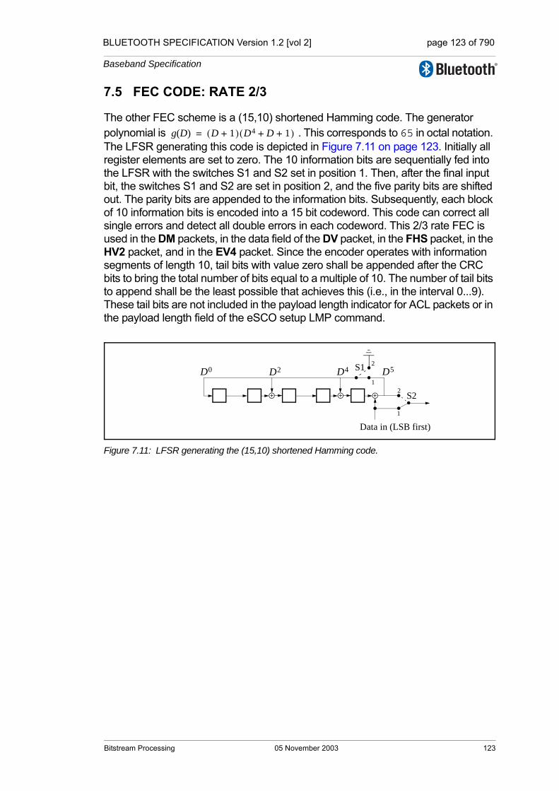
BLUETOOTH SPECIFICATION Version 1.2 [vol 2] page 123 of 790
Baseband Specification
7.5 FEC CODE: RATE 2/3
The other FEC scheme is a (15,10) shortened Hamming code. The generator polynomial is . This corresponds to 65 in octal notation. The LFSR generating this code is depicted in Figure 7.11 on page 123. Initially all register elements are set to zero. The 10 information bits are sequentially fed into the LFSR with the switches S1 and S2 set in position 1. Then, after the final input bit, the switches S1 and S2 are set in position 2, and the five parity bits are shifted out. The parity bits are appended to the information bits. Subsequently, each block of 10 information bits is encoded into a 15 bit codeword. This code can correct all single errors and detect all double errors in each codeword. This 2/3 rate FEC is used in the DM packets, in the data field of the DV packet, in the FHS packet, in the HV2 packet, and in the EV4 packet. Since the encoder operates with information segments of length 10, tail bits with value zero shall be appended after the CRC bits to bring the total number of bits equal to a multiple of 10. The number of tail bits to append shall be the least possible that achieves this (i.e., in the interval 0...9). These tail bits are not included in the payload length indicator for ACL packets or in the payload length field of the eSCO setup LMP command.
Figure 7.11: LFSR generating the (15,10) shortened Hamming code.
g D( ) D 1+( ) D4 D 1+ +( )=
Data in (LSB first)
D5D4D2D0 S11
2
S2
1
2
Bitstream Processing 05 November 2003 123

BLUETOOTH SPECIFICATION Version 1.2 [vol 2] page 124 of 790
Baseband Specification
7.6 ARQ SCHEME
With an automatic repeat request scheme, DM, DH the data field of DV packets, and EV packets shall be transmitted until acknowledgement of a successful recep-tion is returned by the destination (or timeout is exceeded). The acknowledgement information shall be included in the header of the return packet. The ARQ scheme is only used on the payload in the packet and only on packets that have a CRC. The packet header and the synchronous data payload of HV and DV packets are not protected by the ARQ scheme.
7.6.1 Unnumbered ARQ
Bluetooth uses a fast, unnumbered acknowledgment scheme. An ACK (ARQN=1) or a NAK (ARQN=0) is returned in response to the receipt of previ-ously received packet. The slave shall respond in the slave-to-master slot directly following the master-to-slave slot unless the slave has scatternet com-mitments in that timeslot; the master shall respond at the next event address-ing the same slave (the master may have addressed other slaves between the last received packet from the considered slave and the master response to this packet). For a packet reception to be successful, at least the HEC must pass. In addition, the CRC must pass if present.
In the first POLL packet at the start of a new connection (as a result of a page, page scan, role switch or unpark) the master shall initialize the ARQN bit to NAK. The response packet sent by the slave shall also have the ARQN bit set to NAK. The subsequent packets shall use the following rules. The initial value of the master’s eSCO ARQN at link set-up shall be NAK.
The ARQ bit shall only be affected by data packets containing CRC and empty slots. As shown in Figure 7.12 on page 125, upon successful reception of a CRC packet, the ARQN bit shall be set to ACK. If, in any receive slot in the slave, or, in a receive slot in the master following transmission of a packet, one of these events applies:
1. no access code is detected,
2. the HEC fails,
3. the CRC fails,
then the ARQN bit shall be set to NAK. In eSCO the ARQN bit may be set to ACK even when the CRC on an EV packet has failed thus enabling delivery of erroneous packets.
Packets that have correct HEC but that are addressed to other slaves, or pack-ets other than DH, DM, DV or EV packets, shall not affect the ARQN bit, except as noted in Section 7.6.2.2 on page 128. In these cases the ARQN bit shall be left as it was prior to reception of the packet. For ACL packets, if a CRC packet with a correct header has the same SEQN as the previously received CRC packet, the ARQN bit shall be set to ACK and the payload shall be ignored without checking the CRC. For eSCO packets, the SEQN shall not be used
124 05 November 2003 Bitstream Processing
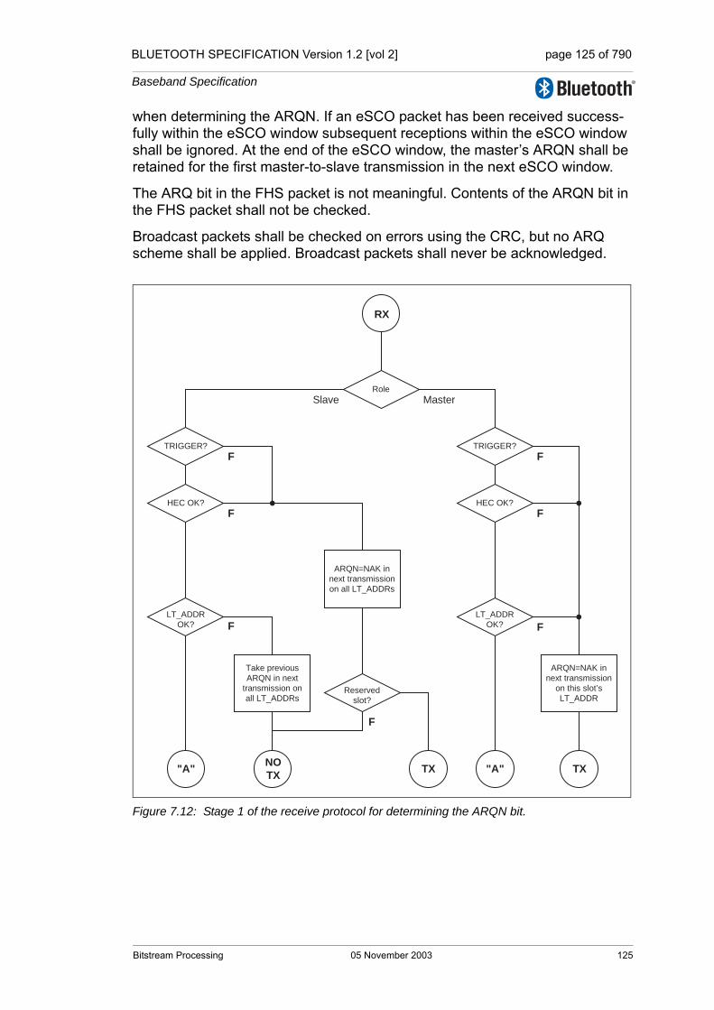
BLUETOOTH SPECIFICATION Version 1.2 [vol 2] page 125 of 790
Baseband Specification
when determining the ARQN. If an eSCO packet has been received success-fully within the eSCO window subsequent receptions within the eSCO window shall be ignored. At the end of the eSCO window, the master’s ARQN shall be retained for the first master-to-slave transmission in the next eSCO window.
The ARQ bit in the FHS packet is not meaningful. Contents of the ARQN bit in the FHS packet shall not be checked.
Broadcast packets shall be checked on errors using the CRC, but no ARQ scheme shall be applied. Broadcast packets shall never be acknowledged.
Figure 7.12: Stage 1 of the receive protocol for determining the ARQN bit.
Slave MasterRole
TRIGGER?
HEC OK?
LT_ADDROK?
F
F
ARQN=NAK innext transmissionon all LT_ADDRs
Take previousARQN in next
transmission onall LT_ADDRs
TRIGGER?
HEC OK?
LT_ADDROK?
F
F
ARQN=NAK innext transmission
on this slot’sLT_ADDR
FF
Reservedslot?
F
RX
"A" TXNO�TX "A" TX
Bitstream Processing 05 November 2003 125

BLUETOOTH SPECIFICATION Version 1.2 [vol 2] page 126 of 790
Baseband Specification
Figure 7.13: Stage 2 (ACL) of the receive protocol for determining the ARQN bit.
PacketType?
SEQN =SEQNOLD
CRC OK?
Ignore payload Accept payload Reject payload
ARQN=ACK innext transmission
on ACLLT_ADDR
SEQNOLD =SEQN
F
F
eSCOLT_ADDR?
F
POLL/NULL/HV/AUX1
ARQN=NAK innext transmission
on ACLLT_ADDR
F
Take previousARQN in next
transmission onACL LT_ADDR
DM/DH/DV
SEQN =SEQNOLD
Accept PayloadAccept Payload
TX
"A"
"B"
126 05 November 2003 Bitstream Processing

BLUETOOTH SPECIFICATION Version 1.2 [vol 2] page 127 of 790
Baseband Specification
Figure 7.14: Stage 2 (eSCO) of the receive protocol for determining the ARQN bit.
7.6.2 Retransmit filtering
The data payload shall be transmitted until a positive acknowledgment is received or a timeout is exceeded. A retransmission shall be carried out either because the packet transmission itself failed, or because the acknowledgment transmitted in the return packet failed (note that the latter has a lower failure probability since the header is more heavily coded). In the latter case, the des-tination keeps receiving the same payload over and over again. In order to filter out the retransmissions in the destination, the SEQN bit is present in the header. Normally, this bit is alternated for every new CRC data payload trans-mission. In case of a retransmission, this bit shall not be changed so the desti-nation can compare the SEQN bit with the previous SEQN value. If different, a new data payload has arrived; otherwise it is the same data payload and may be ignored. Only new data payloads shall be transferred to the Baseband Resource Manager. Note that CRC data payloads can be carried only by DM, DH, DV or EV packets.
Ignore payload
Packet OK?F
F
Already received valid
payload in this eSCO
window
Reject payload
ARQN=NAK innext transmission
on eSCOLT_ADDR
Accept payload
ARQN=ACK innext transmission
on eSCOLT_ADDR
"B"
TX
Bitstream Processing 05 November 2003 127
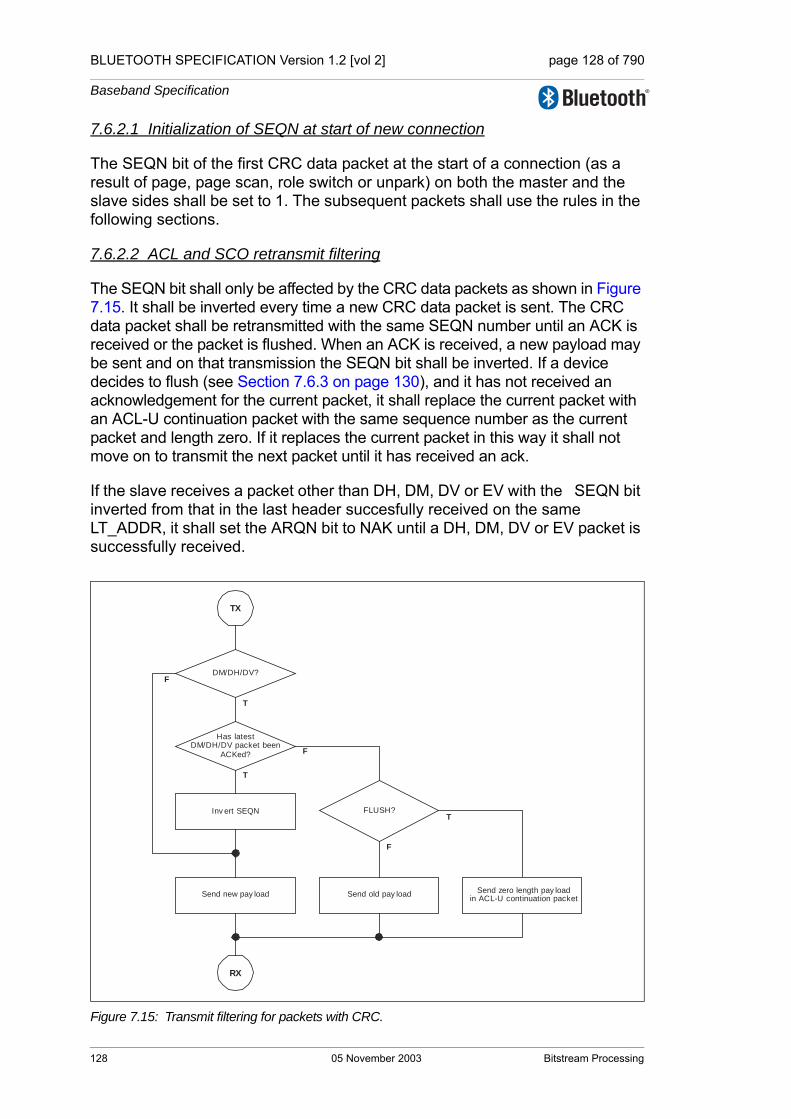
BLUETOOTH SPECIFICATION Version 1.2 [vol 2] page 128 of 790
Baseband Specification
7.6.2.1 Initialization of SEQN at start of new connection
The SEQN bit of the first CRC data packet at the start of a connection (as a result of page, page scan, role switch or unpark) on both the master and the slave sides shall be set to 1. The subsequent packets shall use the rules in the following sections.
7.6.2.2 ACL and SCO retransmit filtering
The SEQN bit shall only be affected by the CRC data packets as shown in Figure 7.15. It shall be inverted every time a new CRC data packet is sent. The CRC data packet shall be retransmitted with the same SEQN number until an ACK is received or the packet is flushed. When an ACK is received, a new payload may be sent and on that transmission the SEQN bit shall be inverted. If a device decides to flush (see Section 7.6.3 on page 130), and it has not received an acknowledgement for the current packet, it shall replace the current packet with an ACL-U continuation packet with the same sequence number as the current packet and length zero. If it replaces the current packet in this way it shall not move on to transmit the next packet until it has received an ack.
If the slave receives a packet other than DH, DM, DV or EV with the SEQN bit inverted from that in the last header succesfully received on the same LT_ADDR, it shall set the ARQN bit to NAK until a DH, DM, DV or EV packet is successfully received.
Figure 7.15: Transmit filtering for packets with CRC.
DM/DH/DV?
Inv ert SEQN
TX
RX
FLUSH?
Send old pay loadSend new pay load
Has latestDM/DH/DV packet been
ACKed?
Send zero length pay loadin ACL-U continuation packet
F
T
T
T
F
F
128 05 November 2003 Bitstream Processing
BLUETOOTH SPECIFICATION Version 1.2 [vol 2] page 129 of 790
Baseband Specification
7.6.2.3 eSCO retransmit filtering
In eSCO, the SEQN bit shall be toggled every eSCO window. The value shall be constant for the duration of the eSCO window. The initial value of SEQN shall be zero.
For a given eSCO window the SEQN value shall be constant.
7.6.2.4 FHS retransmit filtering
The SEQN bit in the FHS packet is not meaningful. This bit may be set to any value. Contents of the SEQN bit in the FHS packet shall not be checked.
7.6.2.5 Packets without CRC retransmit filtering
During transmission of packets without a CRC the SEQN bit shall remain the same as it was in the previous packet.
Bitstream Processing 05 November 2003 129
BLUETOOTH SPECIFICATION Version 1.2 [vol 2] page 130 of 790
Baseband Specification
7.6.3 Flushing payloads
In ACL, the ARQ scheme can cause variable delay in the traffic flow since retransmissions are inserted to assure error-free data transfer. For certain communication links, only a limited amount of delay is allowed: retransmissions are allowed up to a certain limit at which the current payload shall be ignored. This data transfer is indicated as isochronous traffic. This means that the retransmit process must be overruled in order to continue with the next data payload. Aborting the retransmit scheme is accomplished by flushing the old data and forcing the link controller to take the next data instead.
Flushing results in loss of remaining portions of an L2CAP message. There-fore, the packet following the flush shall have a start packet indication of LLID = 10 in the payload header for the next L2CAP message. This informs the desti-nation of the flush. (see Section 6.6 on page 112). Flushing will not necessarily result in a change in the SEQN bit value, see the previous section.
The Flush Timeout defines a maximum period after which all segments of the ACL-U packet are flushed from the Controller buffer. The Flush Timeout shall start when the First segment of the ACL-U packet is stored in the Controller buffer. After the Flush timeout has expired the Link Controller may continue transmissions according to the procedure described in Section 7.6.2.2 on page 128, however the Baseband Resource Manager shall not continue the trans-mission of the ACL-U packet to the Link Controller. If the Baseband Resource Manager has further segments of the packet queued for transmission to the Link Controller it shall delete the remaining segments of the ACL-U packet from the queue. In case the complete ACL-U packet was not stored in the Controller buffer yet, any Continuation segments, received for the ACL logical transport, shall be flushed, until a First segment is received. When the complete ACL-U packet has been flushed, the Link Manager shall continue transmission of the next ACL-U packet for the ACL logical transport. The default Flush Timeout shall be infinite, i.e. re-transmissions are carried out until physical link loss occurs. This is also referred to as a 'reliable channel'. All devices shall support the default Flush Timeout.
In eSCO, packets shall be automatically flushed at the end of the eSCO win-dow.
7.6.4 Multi-slave considerations
In a piconet with multiple logical transports, the master shall carry out the ARQ protocol independently on each logical transport.
7.6.5 Broadcast packets
Broadcast packets are packets transmitted by the master to all the slaves simultaneously. If multiple hop sequences are being used each transmission may only be received by some of the slaves. In this case the master shall repeat the transmission on each hop sequence. A broadcast packet shall be
130 05 November 2003 Bitstream Processing
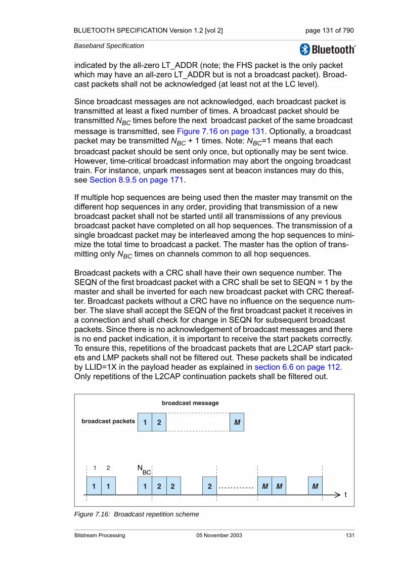
BLUETOOTH SPECIFICATION Version 1.2 [vol 2] page 131 of 790
Baseband Specification
indicated by the all-zero LT_ADDR (note; the FHS packet is the only packet which may have an all-zero LT_ADDR but is not a broadcast packet). Broad-cast packets shall not be acknowledged (at least not at the LC level).
Since broadcast messages are not acknowledged, each broadcast packet is transmitted at least a fixed number of times. A broadcast packet should be transmitted NBC times before the next broadcast packet of the same broadcast message is transmitted, see Figure 7.16 on page 131. Optionally, a broadcast packet may be transmitted NBC + 1 times. Note: NBC=1 means that each broadcast packet should be sent only once, but optionally may be sent twice. However, time-critical broadcast information may abort the ongoing broadcast train. For instance, unpark messages sent at beacon instances may do this, see Section 8.9.5 on page 171.
If multiple hop sequences are being used then the master may transmit on the different hop sequences in any order, providing that transmission of a new broadcast packet shall not be started until all transmissions of any previous broadcast packet have completed on all hop sequences. The transmission of a single broadcast packet may be interleaved among the hop sequences to mini-mize the total time to broadcast a packet. The master has the option of trans-mitting only NBC times on channels common to all hop sequences.
Broadcast packets with a CRC shall have their own sequence number. The SEQN of the first broadcast packet with a CRC shall be set to SEQN = 1 by the master and shall be inverted for each new broadcast packet with CRC thereaf-ter. Broadcast packets without a CRC have no influence on the sequence num-ber. The slave shall accept the SEQN of the first broadcast packet it receives in a connection and shall check for change in SEQN for subsequent broadcast packets. Since there is no acknowledgement of broadcast messages and there is no end packet indication, it is important to receive the start packets correctly. To ensure this, repetitions of the broadcast packets that are L2CAP start pack-ets and LMP packets shall not be filtered out. These packets shall be indicated by LLID=1X in the payload header as explained in section 6.6 on page 112. Only repetitions of the L2CAP continuation packets shall be filtered out.
Figure 7.16: Broadcast repetition scheme
NBC
t1 1 1 2 2 2 M
1 2 M
M M
1 2
broadcast message
broadcast packets
Bitstream Processing 05 November 2003 131

BLUETOOTH SPECIFICATION Version 1.2 [vol 2] page 132 of 790
Baseband Specification
132 05 November 2003 Bitstream Processing

BLUETOOTH SPECIFICATION Version 1.2 [vol 2] page 133 of 790
Baseband Specification
8 LINK CONTROLLER OPERATION
This section describes how a piconet is established and how devices can be added to and released from the piconet. Several states of operation of the devices are defined to support these functions. In addition, the operation of several piconets with one or more common members, the scatternet, is dis-cussed.
8.1 OVERVIEW OF STATES
Figure 8.1 on page 133 shows a state diagram illustrating the different states used in the link controller. There are three major states: STANDBY, CONNEC-TION, and PARK; in addition, there are seven substates, page, page scan, inquiry, inquiry scan, master response, slave response, and inquiry response. The substates are interim states that are used to establish connec-tions and enable device discovery. To move from one state or substate to another, either commands from the link manager are used, or internal signals in the link controller are used (such as the trigger signal from the correlator and the timeout signals).
.
Figure 8.1: State diagram of link controller.
CONNECTION
STANDBY
Page Page ScanInquiryScan
MasterResponse
InquiryResponse
Inquiry
SlaveResponse
PARK
Link Controller Operation 05 November 2003 133
BLUETOOTH SPECIFICATION Version 1.2 [vol 2] page 134 of 790
Baseband Specification
8.2 STANDBY STATE
The STANDBY state is the default state in the device. In this state, the device may be in a low-power mode. Only the native clock is running at the accuracy of the LPO (or better).
The controller may leave the STANDBY state to scan for page or inquiry mes-sages, or to page or inquiry itself.
8.3 CONNECTION ESTABLISHMENT SUBSTATES
In order to establish new connections the paging procedure is used. Only the Bluetooth device address is required to set up a connection. Knowledge about the clock, obtained from the inquiry procedure (see Section 8.4 on page 143) or from a previous connection with this device, and the page scanning mode of the other device will accelerate the setup procedure. A device that establishes a connection carries out a page procedure and will automatically become the master of the connection.
8.3.1 Page scan substate
In the page scan substate, a device may be configured to use either the stan-dard or interlaced scanning procedure. During a standard scan, a device lis-tens for the duration of the scan window Tw_page_scan (11.25ms default, see HCI [Part E] Section 7.3.20 on page 467), while the interlaced scan is per-formed as two back to back scans of Tw_page_scan. If the scan interval is not at least twice the scan window, then interlaced scan shall not be used. During each scan window, the device shall listen at a single hop frequency, its correla-tor matched to its device access code (DAC). The scan window shall be long enough to completely scan 16 page frequencies.
When a device enters the page scan substate, it shall select the scan fre-quency according to the page hopping sequence determined by the device's Bluetooth device address, see Section 2.6.4.1 on page 79. The phase in the sequence shall be determined by CLKN16-12 of the device’s native clock; that is, every 1.28s a different frequency is selected.
In the case of a standard scan, if the correlator exceeds the trigger threshold during the page scan, the device shall enter the slave response substate described in Section 8.3.3.1 on page 140. The scanning device may also use interlaced scan. In this case, if the correlator does not exceed the trigger threshold during the first scan it shall scan a second time using the phase in the sequence determined by [CLKN16-12 + 16] mod 32. If on this second scan the correlator exceeds the trigger threshold the device shall enter the slave response substate using [CLKN16-12 + 16] mod 32 as the frozen CLKN* in the calculation for Xprs(79), see Section 2.6.4.3 on page 80 for details. If the corre-lator does not exceed the trigger threshold during a scan in normal mode or
134 05 November 2003 Link Controller Operation

BLUETOOTH SPECIFICATION Version 1.2 [vol 2] page 135 of 790
Baseband Specification
during the second scan in interlaced scan mode it shall return to either the STANDBY or CONNECTION state.
The page scan substate can be entered from the STANDBY state or the CON-NECTION state. In the STANDBY state, no connection has been established and the device can use all the capacity to carry out the page scan. Before entering the page scan substate from the CONNECTION state, the device should reserve as much capacity as possible for scanning. If desired, the device may place ACL connections in Hold, Park or Sniff, see Section 8.8 on page 165 and Section 8.9 on page 165. Synchronous connections should not be interrupted by the page scan, although eSCO retransmissions should be paused during the scan. The page scan may be interrupted by the reserved synchronous slots which should have higher priority than the page scan. SCO packets should be used requiring the least amount of capacity (HV3 packets). The scan window shall be increased to minimize the setup delay. If one SCO logical transport is present using HV3 packets and TSCO=6 slots or one eSCO logical transport is present using EV3 packets and TESCO=6 slots, a total scan window Tw page scan of at least 36 slots (22.5ms) is recommended; if two SCO links are present using HV3 packets and TSCO=6 slots or two eSCO links are present using EV3 packets and TESCO=6 slots, a total scan window of at least 54 slots (33.75ms) is recommended.
The scan interval Tpage scan is defined as the interval between the beginnings of two consecutive page scans. A distinction is made between the case where the scan interval is equal to the scan window Tw page scan (continuous scan), the scan interval is maximal 1.28s, or the scan interval is maximal 2.56s. These three cases shall determine the behavior of the paging device; that is, whether the paging device shall use R0, R1 or R2, see also Section 8.3.2 on page 136. Table 8.1 illustrates the relationship between Tpage scan and modes R0, R1 and R2. Although scanning in the R0 mode is continuous, the scanning may be interrupted for example by reserved synchronous slots. The scan interval infor-mation is included in the SR field in the FHS packet.
SR mode Tpage scan
R0 ≤ 1.28s and = Tw page scan
R1 ≤ 1.28s
R2 ≤ 2.56s
Reserved -
Table 8.1: Relationship between scan interval, and paging modes R0, R1 and R2.
Link Controller Operation 05 November 2003 135
BLUETOOTH SPECIFICATION Version 1.2 [vol 2] page 136 of 790
Baseband Specification
8.3.2 Page substate
The page substate is used by the master (source) to activate and connect to a slave (destination) in the page scan substate. The master tries to coincide with the slave's scan activity by repeatedly transmitting the paging message con-sisting of the slave’s device access code (DAC) in different hop channels. Since the Bluetooth clocks of the master and the slave are not synchronized, the master does not know exactly when the slave wakes up and on which hop frequency. Therefore, it transmits a train of identical page scan messages at different hop frequencies and listens in between the transmit intervals until it receives a response from the slave.
The page procedure in the master consists of a number of steps. First, the Host communicates the BD_ADDR of the slave to the Controller. This BD_ADDR shall be used by the master to determine the page hopping sequence, see Section 2.6.4.2 on page 80. The slave’s BD_ADDR shall be used to determine the page hopping sequence, see Section 2.6.4.2 on page 80. For the phase in the sequence, the master shall use an estimate of the slave’s clock. For exam-ple, this estimate can be derived from timing information that was exchanged during the last encounter with this particular device (which could have acted as a master at that time), or from an inquiry procedure. With this estimate CLKE of the slave’s Bluetooth clock, the master can predict on which hop channel the slave starts page scanning.
The estimate of the Bluetooth clock in the slave can be completely wrong. Although the master and the slave use the same hopping sequence, they use different phases in the sequence and might never select the same frequency. To compensate for the clock drifts, the master shall send its page message dur-ing a short time interval on a number of wake-up frequencies. It shall transmit also on hop frequencies just before and after the current, predicted hop fre-quency. During each TX slot, the master shall sequentially transmit on two dif-ferent hop frequencies. In the following RX slot, the receiver shall listen sequentially to two corresponding RX hops for ID packet. The RX hops shall be selected according to the page response hopping sequence. The page response hopping sequence is strictly related to the page hopping sequence: for each page hop there is a corresponding page response hop. The RX/TX timing in the page substate is described in Section 2.2.5 on page 60, see also Figure 2.7 on page 65. In the next TX slot, it shall transmit on two hop frequen-cies different from the former ones. Note: The hop rate is increased to 3200 hops/s.
With the increased hopping rate as described above, the transmitter can cover 16 different hop frequencies in 16 slots or 10 ms. The page hopping sequence is divided over two paging trains A and B of 16 frequencies. Train A includes the 16 hop frequencies surrounding the current, predicted hop frequency f(k), where k is determined by the clock estimate CLKE16-12. The first train consists of hops
f(k-8), f(k-7),...,f(k),...,f(k+7)
136 05 November 2003 Link Controller Operation
BLUETOOTH SPECIFICATION Version 1.2 [vol 2] page 137 of 790
Baseband Specification
When the difference between the Bluetooth clocks of the master and the slave is between -8x1.28 s and +7x1.28 s, one of the frequencies used by the master will be the hop frequency the slave will listen to. Since the master does not know when the slave will enter the page scan substate, the master has to repeat this train A Npage times or until a response is obtained, whichever is shorter. If the slave scan interval corresponds to R1, the repetition number is at least 128; if the slave scan interval corresponds to R2 or if the master has not previously read the slave's SR mode, the repetition number is at least 256. If the master has not previously read the slave's SR mode it shall use Npage >= 256. Note that CLKE16-12 changes every 1.28 s; therefore, every 1.28 s, the trains will include different frequencies of the page hopping set.
When the difference between the Bluetooth clocks of the master and the slave is less than -8x1.28 s or larger than +7x1.28 s, the remaining 16 hops are used to form the new 10 ms train B. The second train consists of hops
f(k-16), f(k-15),...,f(k-9),f(k+8)...,f(k+15)
Train B shall be repeated for Npage times. If no response is obtained, train A shall be tried again Npage times. Alternate use of train A and train B shall be continued until a response is received or the timeout pageTO is exceeded. If a response is returned by the slave, the master device enters the master response substate.
The page substate may be entered from the STANDBY state or the CONNEC-TION state. In the STANDBY state, no connection has been established and the device can use all the capacity to carry out the page. Before entering the page substate from the CONNECTION state, the device should free as much capacity as possible for scanning. To ensure this, it is recommended that the ACL connections are put on hold or park. However, the synchronous connec-tions shall not be disturbed by the page. This means that the page will be inter-rupted by the reserved SCO and eSCO slots which have higher priority than the page. In order to obtain as much capacity for paging, it is recommended to use the SCO packets which use the least amount of capacity (HV3 packets). If SCO or eSCO links are present, the repetition number Npage of a single train shall be increased, see Table 8.2. Here it has been assumed that the HV3 packet are used with an interval TSCO=6 slots or EV3 packets are used with an interval of TESCO=6 slots, which would correspond to a 64 kb/s synchronous link.
Link Controller Operation 05 November 2003 137
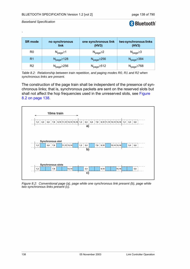
BLUETOOTH SPECIFICATION Version 1.2 [vol 2] page 138 of 790
Baseband Specification
.
The construction of the page train shall be independent of the presence of syn-chronous links; that is, synchronous packets are sent on the reserved slots but shall not affect the hop frequencies used in the unreserved slots, see Figure 8.2 on page 138.
Figure 8.2: Conventional page (a), page while one synchronous link present (b), page while two synchronous links present (c).
SR mode no synchronouslink
one synchronous link (HV3)
two synchronous links (HV3)
R0 Npage≥1 Npage≥2 Npage≥3
R1 Npage≥128 Npage≥256 Npage≥384
R2 Npage≥256 Npage≥512 Npage≥768
Table 8.2: Relationship between train repetition, and paging modes R0, R1 and R2 when synchronous links are present.
Synchronous slot
Synchronous slots
a)
b)
c)
10ms train
1,2 3,4 5,6 7,8 9,10 11,12 13,14 15,16 1,2 3,4 5,6 7,8 9,10 11,12 13,14 15,16 1,2 3,4 5,6
3,4 5,61,2 3,4 7,8 9,10 13,14 15,161,2 5,6 7,8 11,12 13,14
5,63,4 9,10 15,161,2 7,8 13,14
138 05 November 2003 Link Controller Operation
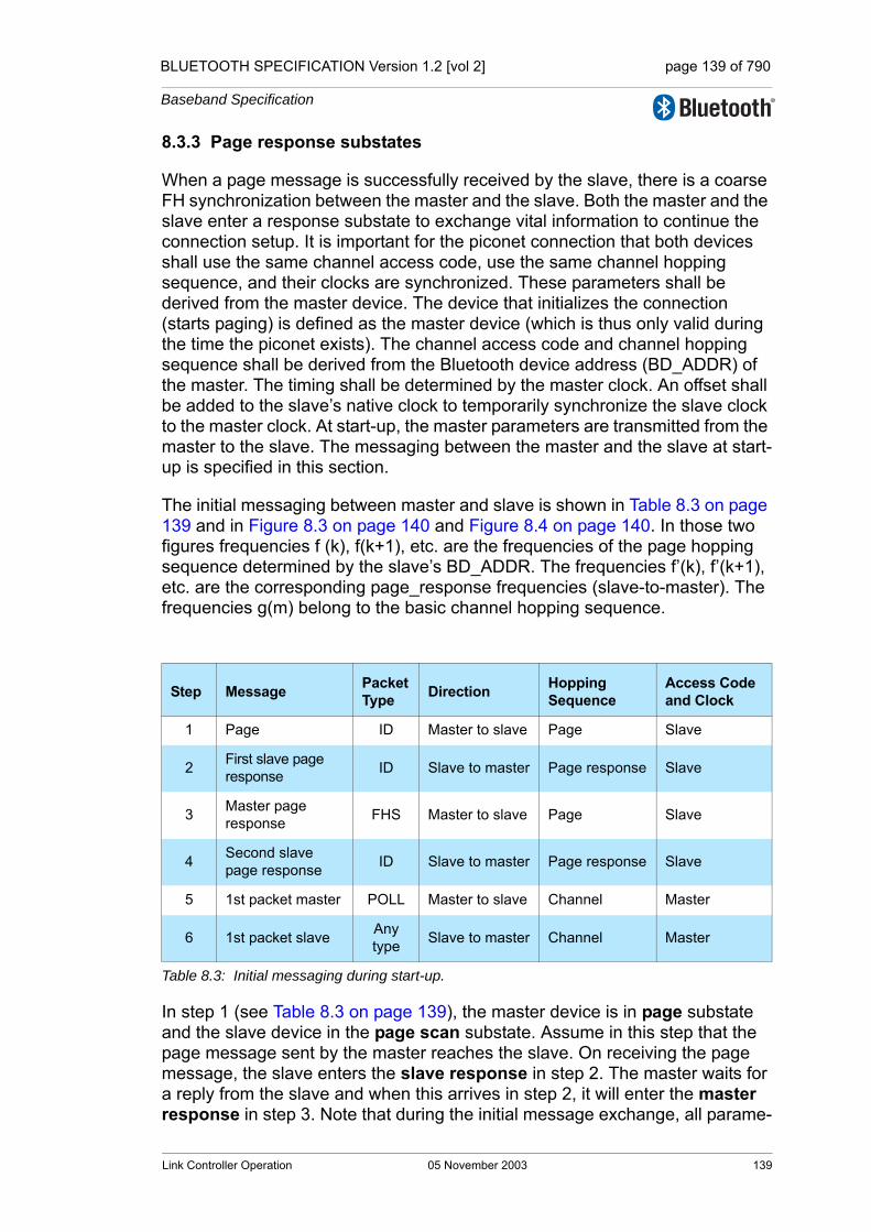
BLUETOOTH SPECIFICATION Version 1.2 [vol 2] page 139 of 790
Baseband Specification
8.3.3 Page response substates
When a page message is successfully received by the slave, there is a coarse FH synchronization between the master and the slave. Both the master and the slave enter a response substate to exchange vital information to continue the connection setup. It is important for the piconet connection that both devices shall use the same channel access code, use the same channel hopping sequence, and their clocks are synchronized. These parameters shall be derived from the master device. The device that initializes the connection (starts paging) is defined as the master device (which is thus only valid during the time the piconet exists). The channel access code and channel hopping sequence shall be derived from the Bluetooth device address (BD_ADDR) of the master. The timing shall be determined by the master clock. An offset shall be added to the slave’s native clock to temporarily synchronize the slave clock to the master clock. At start-up, the master parameters are transmitted from the master to the slave. The messaging between the master and the slave at start-up is specified in this section.
The initial messaging between master and slave is shown in Table 8.3 on page 139 and in Figure 8.3 on page 140 and Figure 8.4 on page 140. In those two figures frequencies f (k), f(k+1), etc. are the frequencies of the page hopping sequence determined by the slave’s BD_ADDR. The frequencies f’(k), f’(k+1), etc. are the corresponding page_response frequencies (slave-to-master). The frequencies g(m) belong to the basic channel hopping sequence.
In step 1 (see Table 8.3 on page 139), the master device is in page substate and the slave device in the page scan substate. Assume in this step that the page message sent by the master reaches the slave. On receiving the page message, the slave enters the slave response in step 2. The master waits for a reply from the slave and when this arrives in step 2, it will enter the master response in step 3. Note that during the initial message exchange, all parame-
Step Message PacketType Direction Hopping
SequenceAccess Code and Clock
1 Page ID Master to slave Page Slave
2 First slave page response ID Slave to master Page response Slave
3 Master page response FHS Master to slave Page Slave
4 Second slave page response ID Slave to master Page response Slave
5 1st packet master POLL Master to slave Channel Master
6 1st packet slave Any type Slave to master Channel Master
Table 8.3: Initial messaging during start-up.
Link Controller Operation 05 November 2003 139
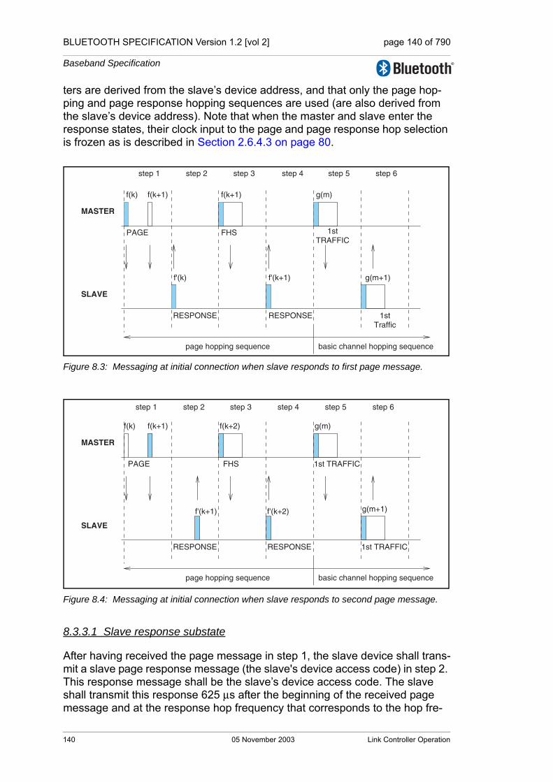
BLUETOOTH SPECIFICATION Version 1.2 [vol 2] page 140 of 790
Baseband Specification
ters are derived from the slave’s device address, and that only the page hop-ping and page response hopping sequences are used (are also derived from the slave’s device address). Note that when the master and slave enter the response states, their clock input to the page and page response hop selection is frozen as is described in Section 2.6.4.3 on page 80.
Figure 8.3: Messaging at initial connection when slave responds to first page message.
Figure 8.4: Messaging at initial connection when slave responds to second page message.
8.3.3.1 Slave response substate
After having received the page message in step 1, the slave device shall trans-mit a slave page response message (the slave's device access code) in step 2. This response message shall be the slave’s device access code. The slave shall transmit this response 625 µs after the beginning of the received page message and at the response hop frequency that corresponds to the hop fre-
f(k)
f'(k)
page hopping sequence basic channel hopping sequence
MASTER
SLAVE
f'(k+1) g(m+1)
g(m)f(k+1)f(k+1)
PAGE
RESPONSE RESPONSE 1stTraffic
1stTRAFFIC
step 1 step 2 step 3 step 4 step 5 step 6
FHS
f(k)
page hopping sequence basic channel hopping sequence
MASTER
SLAVE
g(m+1)
g(m)f(k+1)
f'(k+1)
f(k+2)
f'(k+2)
PAGE
1st TRAFFICRESPONSERESPONSE
step 1 step 2 step 3 step 4 step 5 step 6
FHS 1st TRAFFIC
140 05 November 2003 Link Controller Operation
BLUETOOTH SPECIFICATION Version 1.2 [vol 2] page 141 of 790
Baseband Specification
quency in which the page message was received. The slave transmission is therefore time aligned to the master transmission. During initial messaging, the slave shall still use the page response hopping sequence to return information to the master. The clock input CLKN16-12 shall be frozen at the value it had at the time the page message was received.
After having sent the response message, the slave’s receiver shall be activated 312.5 µs after the start of the response message and shall await the arrival of an FHS packet. Note that an FHS packet can arrive 312.5 µs after the arrival of the page message as shown in Figure 8.4 on page 140, and not after 625 µs as is usually the case in the piconet physical channel RX/TX timing. More details about the timing can be found in Section 2.4.4 on page 66.
If the setup fails before the CONNECTION state has been reached, the follow-ing procedure shall be carried out. The slave shall listen as long as no FHS packet is received until pagerespTO is exceeded. Every 1.25 ms, however, it shall select the next master-to-slave hop frequency according to the page hop sequence. If nothing is received after pagerespTO, the slave shall return back to the page scan substate for one scan period. Length of the scan period depends on the synchronous reserved slots present. If no page message is received during this additional scan period, the slave shall resume scanning at its regular scan interval and return to the state it was in prior to the first page scan state.
If an FHS packet is received by the slave in the slave response substate, the slave shall return a slave page response message in step 4 to acknowledge reception of the FHS packet. This response shall use the page response hop-ping sequence. The transmission of the slave page response packet is based on the reception of the FHS packet. Then the slave shall change to the mas-ter's channel access code and clock as received from the FHS packet. Only the 26 MSBs of the master clock are transferred: the timing shall be such that CLK1 and CLK0 are both zero at the time the FHS packet was received as the master transmits in even slots only. The offset between the master’s clock and the slave’s clock shall be determined from the master’s clock in the FHS packet and reported to the slave’s Baseband Resource Manager.
Finally, the slave enters the CONNECTION state in step 5. From then on, the slave shall use the master’s clock and the master's BD_ADDR to determine the basic channel hopping sequence and the channel access code. The slave shall use the LT_ADDR in the FHS payload as the primary LT_ADDR in the CON-NECTION state. The connection mode shall start with a POLL packet transmit-ted by the master. The slave may respond with any type of packet. If the POLL packet is not received by the slave, or the response packet is not received by the master, within newconnectionTO number of slots after FHS packet acknowledgement, the master and the slave shall return to page and page scan substates, respectively. See Section 8.5 on page 148
Link Controller Operation 05 November 2003 141
BLUETOOTH SPECIFICATION Version 1.2 [vol 2] page 142 of 790
Baseband Specification
8.3.3.2 Master response substate
When the master has received a slave page response message in step 2, it shall enter the master response routine. It shall freeze the current clock input to the page hop selection scheme. The master shall then transmit an FHS packet in step 3 containing the master’s real-time Bluetooth clock, the master’s BD_ADDR, the BCH parity bits, and the class of device. The FHS packet con-tains all information to construct the channel access code without requiring a mathematical derivation from the master's Bluetooth device address. The LT_ADDR field in the packet header of FHS packets in the master response substate shall be set to all-zeros. The FHS packet shall be transmitted at the beginning of the master-to-slave slot following the slot in which the slave responded. The FHS packet shall carry the all-zero LT_ADDR. The TX timing of the FHS is not based on the reception of the response packet from the slave. The FHS packet may therefore be sent 312.5 µs after the reception of the response packet like shown in Figure 8.4 on page 140 and not 625 µs after the received packet as is usual in the piconet physical channel RX/TX timing, see also Section 2.4.4 on page 66.
After the master has sent its FHS packet, it shall wait for a second slave page response message in step 4 acknowledging the reception of the FHS packet. This response shall be the slave’s device access code. If no response is received, the master shall retransmit the FHS packet with an updated clock and still using the slave’s parameters. It shall retransmit the FHS packet with the clock updated each time until a second slave page response message is received, or the timeout of pagerespTO is exceeded. In the latter case, the master shall return to the page substate and send an error message to the Baseband Resource Manager. During the retransmissions of the FHS packet, the master shall use the page hopping sequence.
If the slave’s response is received, the master shall change to using the master parameters, so it shall use the channel access code and the master clock. The lower clock bits CLK0 and CLK1 shall be reset to zero at the start of the FHS packet transmission and are not included in the FHS packet. Finally, the master enters the CONNECTION state in step 5. The master BD_ADDR shall be used to change to a new hopping sequence, the basic channel hopping sequence. The basic channel hopping sequence uses all 79 hop channels in a pseudo-random fashion, see also Section 2.6.4.7 on page 82. The master shall now send its first traffic packet in a hop determined with the new (master) parame-ters. This first packet shall be a POLL packet. See Section 8.5 on page 148. This packet shall be sent within newconnectionTO number of slots after recep-tion of the FHS packet acknowledgement. The slave may respond with any type of packet. If the POLL packet is not received by the slave or the POLL packet response is not received by the master within newconnectionTO num-ber of slots, the master and the slave shall return to page and page scan sub-states, respectively.
142 05 November 2003 Link Controller Operation

BLUETOOTH SPECIFICATION Version 1.2 [vol 2] page 143 of 790
Baseband Specification
8.4 DEVICE DISCOVERY SUBSTATES
In order to discover other devices a device shall enter inquiry substate. In this substate, it shall repeatedly transmit the inquiry message (ID packet, see Sec-tion 6.5.1.1 on page 106) at different hop frequencies. The inquiry hop sequence is derived from the LAP of the GIAC. Thus, even when DIACs are used, the applied hopping sequence is generated from the GIAC LAP. A device that allows itself to be discovered, shall regularly enter the inquiry scan sub-state to respond to inquiry messages. The following sections describe the mes-sage exchange and contention resolution during inquiry response. The inquiry response is optional: a device is not forced to respond to an inquiry message.
During the inquiry substate, the discovering device collects the Bluetooth device addresses and clocks of all devices that respond to the inquiry mes-sage. It can then, if desired, make a connection to any one of them by means of the previously described page procedure.
The inquiry message broadcast by the source does not contain any information about the source. However, it may indicate which class of devices should respond. There is one general inquiry access code (GIAC) to inquire for any device, and a number of dedicated inquiry access codes (DIAC) that only inquire for a certain type of device. The inquiry access codes are derived from reserved Bluetooth device addresses and are further described in Section 6.3.1 on page 98.
Link Controller Operation 05 November 2003 143
BLUETOOTH SPECIFICATION Version 1.2 [vol 2] page 144 of 790
Baseband Specification
8.4.1 Inquiry scan substate
The inquiry scan substate is very similar to the page scan substate. However, instead of scanning for the device's device access code, the receiver shall scan for the inquiry access code long enough to completely scan for 16 inquiry frequencies. Two types of scans are defined: standard and interlaced. In the case of a standard scan the length of this scan period is denoted Tw_inquiry_scan (11.25ms default, see HCI [Part E] Section 7.3.22 on page 469). The standard scan is performed at a single hop frequency as defined by Xir4-0 (see Section 2.6.4.6 on page 82). The interlaced scan is performed as two back to back scans of Tw_inquiry_scan where the first scan is on the normal hop frequency and the second scan is defined by [Xir4-0 + 16] mod 32. If the scan interval is not at least twice the scan window then interlaced scan shall not be used. The inquiry procedure uses 32 dedicated inquiry hop frequencies according to the inquiry hopping sequence. These frequencies are determined by the general inquiry address. The phase is determined by the native clock of the device carrying out the inquiry scan; the phase changes every 1.28s.
Instead of, or in addition to, the general inquiry access code, the device may scan for one or more dedicated inquiry access codes. However, the scanning shall follow the inquiry scan hopping sequence determined by the general inquiry address. If an inquiry message is received during an inquiry wake-up period, the device shall enter the inquiry response substate.
The inquiry scan substate can be entered from the STANDBY state or the CONNECTION state. In the STANDBY state, no connection has been estab-lished and the device can use all the capacity to carry out the inquiry scan. Before entering the inquiry scan substate from the CONNECTION state, the device should reserve as much capacity as possible for scanning. If desired, the device may place ACL logical transports in Sniff, Hold, or Park. Synchro-nous logical transports are preferably not interrupted by the inquiry scan, although eSCO retransmissions should be paused during the scan. In this case, the inquiry scan may be interrupted by the reserved synchronous slots. SCO packets should be used requiring the least amount of capacity (HV3 pack-ets). The scan window, Tw inquiry scan, shall be increased to increase the proba-bility to respond to an inquiry message. If one SCO logical transport is present using HV3 packets and TSCO=6 slots or one eSCO logical transport is present using EV3 packets and TESCO=6 slots, a total scan window of at least 36 slots (22.5ms) is recommended; if two SCO links are present using HV3 packets and TSCO=6 slots or two eSCO links are present using EV3 packets and TESCO=6 slots, a total scan window of at least 54 slots (33.75ms) is recom-mended.
The scan interval Tinquiry scan is defined as the interval between two consecutive inquiry scans. The inquiry scan interval shall be less than or equal to 2.56 s.
144 05 November 2003 Link Controller Operation

BLUETOOTH SPECIFICATION Version 1.2 [vol 2] page 145 of 790
Baseband Specification
8.4.2 Inquiry substate
The inquiry substate is used to discover new devices. This substate is very similar to the page substate; the TX/RX timing shall be the same as in paging, see Section 2.4.4 on page 66 and Figure 2.7 on page 65. The TX and RX fre-quencies shall follow the inquiry hopping sequence and the inquiry response hopping sequence, and are determined by the general inquiry access code and the native clock of the discovering device. In between inquiry transmissions, the receiver shall scan for inquiry response messages. When a response is received, the entire packet (an FHS packet) is read, after which the device shall continue with inquiry transmissions. The device in an inquiry substate shall not acknowledge the inquiry response messages. If enabled by the Host (see HCI [Part E] Section 7.3.54 on page 506), the RSSI value of the inquiry response message shall be measured. It shall keep probing at different hop channels and in between listening for response packets. As in the page substate, two 10 ms trains A and B are defined, splitting the 32 frequencies of the inquiry hop-ping sequence into two 16-hop parts. A single train shall be repeated for at least Ninquiry=256 times before a new train is used. In order to collect all responses in an error-free environment, at least three train switches must have taken place. As a result, the inquiry substate may have to last for 10.24 s unless the inquirer collects enough responses and aborts the inquiry substate earlier. If desired, the inquirer may also prolong the inquiry substate to increase the probability of receiving all responses in an error-prone environ-ment. If an inquiry procedure is automatically initiated periodically (say a 10 s period every minute), then the interval between two inquiry instances shall be determined randomly. This is done to avoid two devices synchronizing their inquiry procedures.
The inquiry substate is continued until stopped by the Baseband Resource Manager (when it decides that it has sufficient number of responses), when a timeout has been reached (inquiryTO), or by a command from the host to can-cel the inquiry procedure.
The inquiry substate can be entered from the STANDBY state or the CON-NECTION state. In the STANDBY state, no connection has been established and the device can use all the capacity to carry out the inquiry. Before entering the inquiry substate from the CONNECTION state, the device should free as much capacity as possible for scanning. To ensure this, it is recommended that the ACL logical transports are placed in Sniff, Hold, or Park. However, the reserved slots of synchronous logical transports shall not be disturbed by the inquiry. This means that the inquiry will be interrupted by the reserved SCO and eSCO slots which have higher priority than the inquiry. In order to obtain as much capacity as possible for inquiry, it is recommended to use the SCO pack-ets which use the least amount of capacity (HV3 packets). If SCO or eSCO links are present, the repetition number Ninquiry shall be increased, see Table 8.4 on page 146.Here it has been assumed that HV3 packets are used with an interval TSCO=6
Link Controller Operation 05 November 2003 145
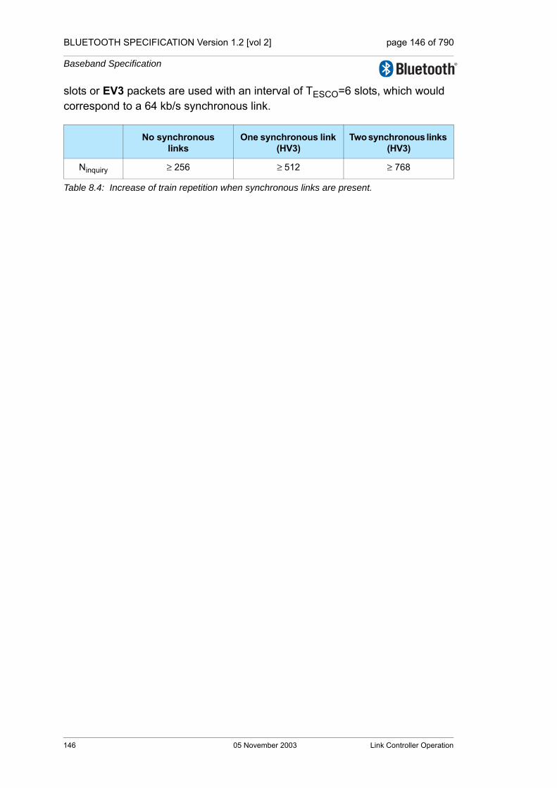
BLUETOOTH SPECIFICATION Version 1.2 [vol 2] page 146 of 790
Baseband Specification
slots or EV3 packets are used with an interval of TESCO=6 slots, which would correspond to a 64 kb/s synchronous link.
No synchronous links
One synchronous link (HV3)
Two synchronous links (HV3)
Ninquiry ≥ 256 ≥ 512 ≥ 768
Table 8.4: Increase of train repetition when synchronous links are present.
146 05 November 2003 Link Controller Operation

BLUETOOTH SPECIFICATION Version 1.2 [vol 2] page 147 of 790
Baseband Specification
8.4.3 Inquiry response substate
The slave response substate for inquiries differs completely from the slave response substate applied for pages. When the inquiry message is received in the inquiry scan substate, the recipient shall return an inquiry response (FHS) packet containing the recipient's device address (BD_ADDR) and other parameters.
The following protocol in the slave's inquiry response shall be used. On the first inquiry message received in this substate the slave shall enter the inquiry response substate and shall return an FHS response packet to the master 625us after the inquiry message was received. A contention problem may arise when several devices are in close proximity to the inquiring device and all respond to an inquiry message at the same time. However, because every device has a free running clock it is highly unlikely that they all use the same phase of the inquiry hopping sequence. In order to avoid repeated collisions between devices that wake up in the same inquiry hop channel simultaneously, a device shall back-off for a random period of time. Thus, if the device receives an inquiry message and returns an FHS packet, it shall generate a random number, RAND, between 0 and MAX_RAND. For scanning intervals ≥ 1.28s MAX_RAND shall be 1023, however, for scanning intervals < 1.28s MAX_RAND may be as small as 127. A profile that uses a special DIAC may choose to use a smaller MAX_RAND than 1023 even when the scanning interval is ≥ 1.28s. The slave shall return to the CONNEC-TION or STANDBY state for the duration of at least RAND time slots. Before returning to the CONNECTION and STANDY state, the device may go through the page scan substate. After at least RAND slots, the device shall add an offset of 1 to the phase in the inquiry hop sequence (the phase has a 1.28 s resolution) and return to the inquiry scan substate again. If the slave is triggered again, it shall repeats the procedure using a new RAND. The offset to the clock accumu-lates each time an FHS packet is returned. During a probing window, a slave may respond multiple times, but on different frequencies and at different times. Reserved synchronous slots should have priority over response packets; that is, if a response packet overlaps with a reserved synchronous slot, it shall not be sent but the next inquiry message is awaited.
The messaging during the inquiry routines is summarized in Table 8.5 on page 147. In step 1, the master transmits an inquiry message using the inquiry access code and its own clock. The slave responds with the FHS packet con-taining the slave’s Bluetooth device address, native clock and other slave infor-mation. This FHS packet is returned at times that tend to be random. The FHS packet is not acknowledged in the inquiry routine, but it is retransmitted at other times and frequencies as long as the master is probing with inquiry messages.
Step Message PacketType Direction Hopping
SequenceAccess Code and Clock
1 Inquiry ID master to slave inquiry inquiry
2 Inquiry response FHS slave to master inquiry response inquiry
Table 8.5: Messaging during inquiry routines.
Link Controller Operation 05 November 2003 147
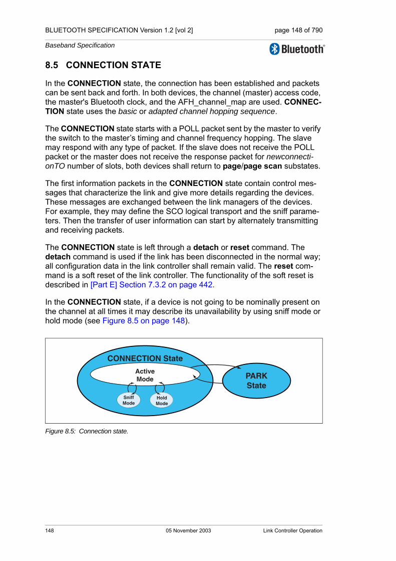
BLUETOOTH SPECIFICATION Version 1.2 [vol 2] page 148 of 790
Baseband Specification
8.5 CONNECTION STATE
In the CONNECTION state, the connection has been established and packets can be sent back and forth. In both devices, the channel (master) access code, the master's Bluetooth clock, and the AFH_channel_map are used. CONNEC-TION state uses the basic or adapted channel hopping sequence.
The CONNECTION state starts with a POLL packet sent by the master to verify the switch to the master’s timing and channel frequency hopping. The slave may respond with any type of packet. If the slave does not receive the POLL packet or the master does not receive the response packet for newconnecti-onTO number of slots, both devices shall return to page/page scan substates.
The first information packets in the CONNECTION state contain control mes-sages that characterize the link and give more details regarding the devices. These messages are exchanged between the link managers of the devices. For example, they may define the SCO logical transport and the sniff parame-ters. Then the transfer of user information can start by alternately transmitting and receiving packets.
The CONNECTION state is left through a detach or reset command. The detach command is used if the link has been disconnected in the normal way; all configuration data in the link controller shall remain valid. The reset com-mand is a soft reset of the link controller. The functionality of the soft reset is described in [Part E] Section 7.3.2 on page 442.
In the CONNECTION state, if a device is not going to be nominally present on the channel at all times it may describe its unavailability by using sniff mode or hold mode (see Figure 8.5 on page 148).
Figure 8.5: Connection state.
CONNECTION State
PARKState
HoldMode
SniffMode
ActiveMode
148 05 November 2003 Link Controller Operation
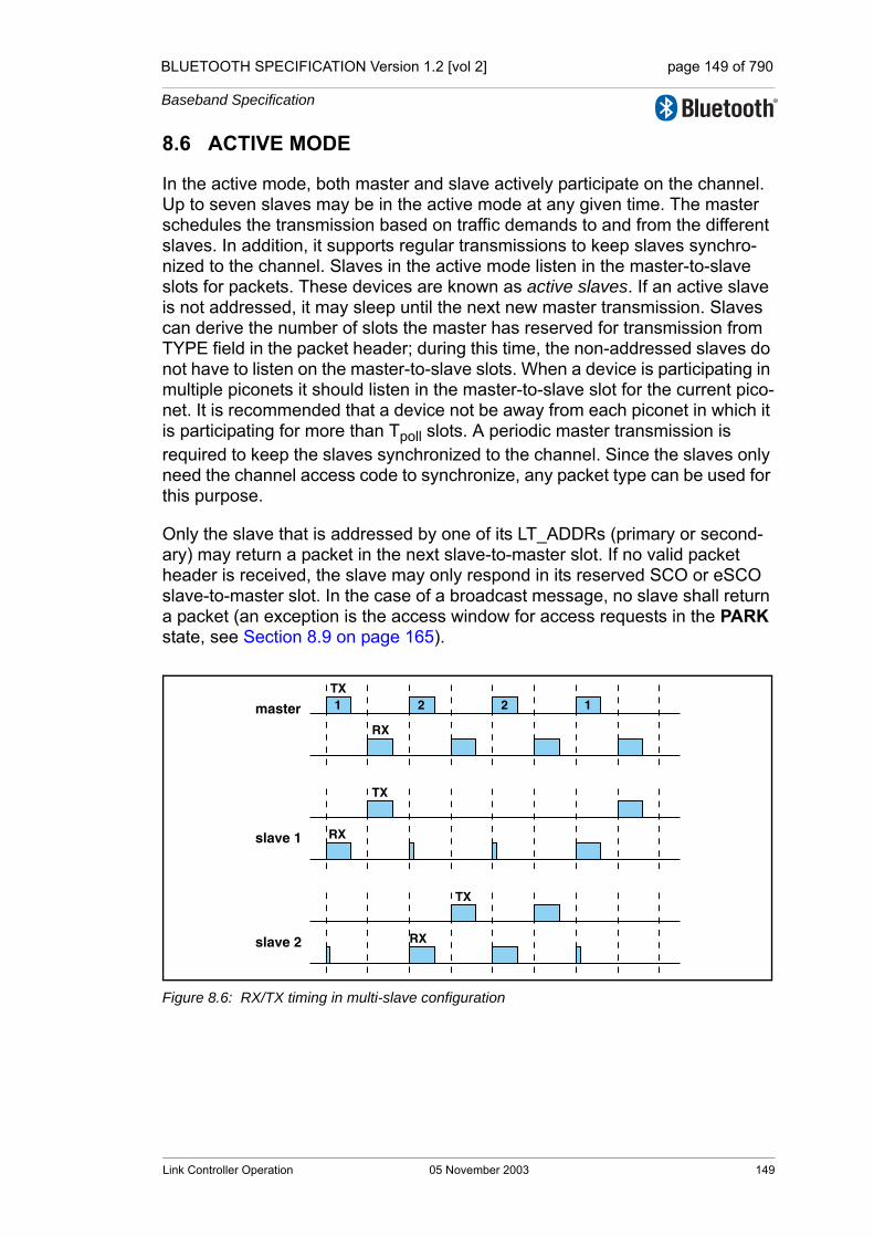
BLUETOOTH SPECIFICATION Version 1.2 [vol 2] page 149 of 790
Baseband Specification
8.6 ACTIVE MODE
In the active mode, both master and slave actively participate on the channel. Up to seven slaves may be in the active mode at any given time. The master schedules the transmission based on traffic demands to and from the different slaves. In addition, it supports regular transmissions to keep slaves synchro-nized to the channel. Slaves in the active mode listen in the master-to-slave slots for packets. These devices are known as active slaves. If an active slave is not addressed, it may sleep until the next new master transmission. Slaves can derive the number of slots the master has reserved for transmission from TYPE field in the packet header; during this time, the non-addressed slaves do not have to listen on the master-to-slave slots. When a device is participating in multiple piconets it should listen in the master-to-slave slot for the current pico-net. It is recommended that a device not be away from each piconet in which it is participating for more than Tpoll slots. A periodic master transmission is required to keep the slaves synchronized to the channel. Since the slaves only need the channel access code to synchronize, any packet type can be used for this purpose.
Only the slave that is addressed by one of its LT_ADDRs (primary or second-ary) may return a packet in the next slave-to-master slot. If no valid packet header is received, the slave may only respond in its reserved SCO or eSCO slave-to-master slot. In the case of a broadcast message, no slave shall return a packet (an exception is the access window for access requests in the PARK state, see Section 8.9 on page 165).
Figure 8.6: RX/TX timing in multi-slave configuration
1 2 2 1TX
RX
TX
TX
RX
RXslave 2
slave 1
master
Link Controller Operation 05 November 2003 149

BLUETOOTH SPECIFICATION Version 1.2 [vol 2] page 150 of 790
Baseband Specification
8.6.1 Polling in the active mode
The master always has full control over the piconet. Due to the TDD scheme, slaves can only communicate with the master and not other slaves. In order to avoid collisions on the ACL logical transport, a slave is only allowed to transmit in the slave-to-master slot when addressed by the LT_ADDR in the packet header in the preceding master-to-slave slot. If the LT_ADDR in the preceding slot does not match, or a valid packet header was not received, the slave shall not transmit.
The master normally attempts to poll a slave's ACL logical transport no less often than once every Tpoll slots. Tpoll is set by the Link Manager (see [Part C] Section 4.1.8 on page 220).
The slave's ACL logical transport may be polled with any packet type except for FHS and ID. For example, polling during SCO may use HV packets, since the slave may respond to an HV packet with a DM1 packet (see Section 8.6.2 on page 150).
8.6.2 SCO
The SCO logical transport shall be established by the master sending an SCO setup message via the LM protocol. This message contains timing parameters including the SCO interval TSCO and the offset DSCO to specify the reserved slots.
In order to prevent clock wrap-around problems, an initialization flag in the LMP setup message indicates whether initialization procedure 1 or 2 is being used. The slave shall apply the initialization method as indicated by the initialization flag. The master shall use initialization 1 when the MSB of the current master clock (CLK27) is 0; it shall use initialization 2 when the MSB of the current mas-ter clock (CLK27) is 1. The master-to-slave SCO slots reserved by the master and the slave shall be initialized on the slots for which the clock satisfies the applicable equation:
CLK27-1 mod TSCO = DSCO for initialization 1
(CLK27,CLK26-1) mod TSCO = DSCO for initialization 2
The slave-to-master SCO slots shall directly follow the reserved master-to-slave SCO slots. After initialization, the clock value CLK(k+1) for the next mas-ter-to-slave SCO slot shall be derived by adding the fixed interval TSCO to the clock value of the current master-to-slave SCO slot:
CLK(k+1) = CLK(k) + TSCO
The master will send SCO packets to the slave at regular intervals (the SCO interval TSCO counted in slots) in the reserved master-to-slave slots. An HV1
150 05 November 2003 Link Controller Operation

BLUETOOTH SPECIFICATION Version 1.2 [vol 2] page 151 of 790
Baseband Specification
packet can carry 1.25ms of speech at a 64 kb/s rate. An HV1 packet shall therefore be sent every two time slots (TSCO=2). An HV2 packet can carry 2.5ms of speech at a 64 kb/s rate. An HV2 packet shall therefore be sent every four time slots (TSCO=4). An HV3 packet can carries 3.75ms of speech at a 64 kb/s rate. An HV3 packet shall therefore be sent every six time slots (TSCO=6).
The slave is allowed to transmit in the slot reserved for its SCO logical trans-port unless the (valid) LT_ADDR in the preceding slot indicates a different slave. If no valid LT_ADDR can be derived in the preceding slot, the slave may still transmit in the reserved SCO slot.
Since the DM1 packet is recognized on the SCO logical transport, it may be sent during the SCO reserved slots if a valid packet header with the primary LT_ADDR is received in the preceeding slot. DM1 packets sent during SCO reserved slots shall only be used to send ACL-C data.
The slave shall not transmit anything other than an HV packet in a reserved SCO slot unless it decodes its own slave address in the packet header of the packet in the preceding master-to-slave transmission slot.
8.6.3 eSCO
The eSCO logical transport is established by the master sending an eSCO setup message via the LM protocol. This message contains timing parameters including the eSCO interval TESCO and the offset DESCO to specify the reserved slots.
To enter eSCO, the master or slave shall send an eSCO setup command via the LM protocol. This message shall contain the eSCO interval TESCO and an offset DESCO. In order to prevent clock wrap-around problems, an initialization flag in the LMP setup message indicates whether initialization procedure 1 or 2 shall be used. The slave shall apply the initialization method as indicated by the initialization flag. The master shall use initialization 1 when the MSB of the current master clock (CLK27) is 0; it shall use initialization 2 when the MSB of the current master clock (CLK27) is 1. The master-to-slave eSCO slots reserved by the master and the slave shall be initialized on the slots for which the clock satisfies the applicable equation:
CLK27-1 mod TESCO = DESCO for initialization 1
(CLK27,CLK26-1) mod TESCO = DESCO for initialization 2
The slave-to-master eSCO slots shall directly follow the reserved master-to-slave eSCO slots. After initialization, the clock value CLK(k+1) for the next master-to-slave eSCO slot shall be found by adding the fixed interval TESCO to the clock value of the current master-to-slave eSCO slot:
CLK(k+1) = CLK(k) + TESCO
Link Controller Operation 05 November 2003 151
BLUETOOTH SPECIFICATION Version 1.2 [vol 2] page 152 of 790
Baseband Specification
When an eSCO logical transport is established, the master shall assign an additional LT_ADDR to the slave. This provides the eSCO logical transport with an ARQ scheme that is separate from that of the ACL logical transport. All traffic on a particular eSCO logical transport, and only that eSCO traffic, is car-ried on the eSCO LT_ADDR. The eSCO ARQ scheme uses the ARQN bit in the packet header, and operates similarly to the ARQ scheme on ACL links.
There are two different polling rules in eSCO. In the eSCO reserved slots, the polling rule is the same as to the SCO reserved slots. The master may send a packet in the master slot. The slave may transmit on the eSCO LT_ADDR in the following slot either if it received a packet on the eSCO LT_ADDR in the previous slot, or if it did not receive a valid packet header in the previous slot. When the master-to-slave packet type is a three-slot packet, the slave’s trans-mit slot is the fourth slot of the eSCO reserved slots. A master shall transmit in an eSCO retransmission window on a given eSCO LT_ADDR only if it addressed that eSCO LT_ADDR in the immediately preceeding eSCO reserved slots. A slave may transmit on an eSCO LT_ADDR in the eSCO reserved slots only if the slave did not received a valid packet header with a dif-ferent LT_ADDR in the eSCO reserved slots. Inside retransmission windows, the same polling rule as for ACL traffic is used: the slave shall transmit on the eSCO channel only if it received a valid packet header and correct LT_ADDR on the eSCO channel in the previous master-to-slave transmission slot. The master may transmit on any non-eSCO LT_ADDR in any master-to-slave transmission slot inside the eSCO retransmission window. The master shall only transmit on an eSCO LT_ADDR in the retransmission window if there are enough slots left in the for both the master and slave packets to complete in the retransmission window. The master may refrain from transmitting in any slot during the eSCO retransmission window. When there is no data to transmit from master to slave, either due to the traffic being unidirectional or due to the master-to-slave packet having been ACK’ed, the master shall use the POLL packet. When the master-to-slave packet has been ACK’ed, and the slave-to-master packet has been correctly received, the master shall not address the slave on the eSCO LT_ADDR until the next eSCO reserved slot, with the exception that the master may transmit a NULL packet with ARQN=ACK on the eSCO LT_ADDR. When there is no data to transmit from slave to master, either due to the traffic being unidirectional or due to the slave-to-master packet hav-ing been ACK'ed, the slave shall use NULL packets. eSCO traffic should be given priority over ACL traffic in the retransmission window.
Figure 8.7 on page 153 shows the eSCO window when single slot packets are used.
152 05 November 2003 Link Controller Operation

BLUETOOTH SPECIFICATION Version 1.2 [vol 2] page 153 of 790
Baseband Specification
Figure 8.7: eSCO Window Details for Single-Slot Packets
When multi-slot packets are used in either direction of the eSCO logical trans-port, the first transmission continues into the following slots. The retransmis-sion window in this case starts the slot after the end of the slave-to-master packet, i.e. two, four or six slots immediately following the eSCO instant are reserved and should not be used for other traffic. Figure 8.8 on page 153 shows the eSCO window when multi-slot packets are used in one direction and single-slot packets are used in the other direction.
Figure 8.8: eSCO Window Details for Asymmetric Traffic
eSCO windows may overlap on the master, but shall not overlap on an individ-ual slave.
In the reserved slots both master and slave shall only listen and transmit at their allocated slots at the first transmission time of each eSCO window. Inter-mittent lapses due to, for instance, time-critical signaling during connection establishment are allowed. Both master and slave may refrain from sending data and may use instead POLL and NULL packets respectively. When the master transmits a POLL packet instead of an EV4 or EV5 packet the slave shall transmit starting in the same slot as if the master transmitted an EV4 or
M
S
M
S
eSCO
Instant
Retransmission
Window
eSCO Window
eSCO
Instant
Retransmission
Window
eSCO Window
S
eSCO
Instant
Retransmission
Window
Reserved
Slots
eSCO Window
M
Link Controller Operation 05 November 2003 153

BLUETOOTH SPECIFICATION Version 1.2 [vol 2] page 154 of 790
Baseband Specification
EV5 packet. If the slave does not receive anything in the reserved master-to-slave transmission slot it shall transmit in the same slot as if the master had transmitted the negotiated packet type. For example, if the master had negoti-ated an EV5 packet the slave would transmit three slots later. [If the master does not receive a slave transmission in response to an eSCO packet it causes an implicit NAK of the packet in question. The listening requirements for the slave during the retransmission window are the same as for an active ACL log-ical transport.
8.6.4 Broadcast scheme
The master of the piconet can broadcast messages to all slaves. A broadcast packet shall have an LT_ADDR set to all zero. Each new broadcast message (which may be carried by a number of packets) shall start with the start of L2CAP message indication (LLID=10).
A broadcast packet shall never be acknowledged. In an error-prone environ-ment, the master may carry out a number of retransmissions to increase the probability for error-free delivery, see also Section 7.6.5 on page 130.
In order to support the PARK state (as described in Section 8.9 on page 165), a master transmission shall take place at fixed intervals. This master transmis-sion will act as a beacon to which slaves can synchronize. If no traffic takes place at the beacon event, broadcast packets shall be sent. More information is given in Section 8.9 on page 165.
154 05 November 2003 Link Controller Operation
BLUETOOTH SPECIFICATION Version 1.2 [vol 2] page 155 of 790
Baseband Specification
8.6.5 Role switch
There are several occasions when a role switch is used.
• a role switch is necessary when joining an existing piconet by paging, since by definition, the paging device is initially master of a "small" piconet only involving the pager (master) and the paged (slave) device.
• a role switch is necessary in order for a slave in an existing piconet to set up a new piconet with itself as master and the original piconet master as slave. If the original piconet had more than one slave, then this implies a double role for the original piconet master; it becomes a slave in the new piconet while still maintaining the original piconet as master.
Prior to the role switch, encryption if present, shall be stopped in the old pico-net. A role switch shall not be performed if the physical link is in Sniff or Hold mode, in the PARK state, or has any synchronous logical transports.
For the master and slave involved in the role switch, the switch results in a reversal of their TX and RX timing: a TDD switch. Additionally, since the pico-net parameters are derived from the Bluetooth device address and clock of the master, a role switch inherently involves a redefinition of the piconet as well: a piconet switch. The new piconet's parameters shall be derived from the former slave's device address and clock.
Assume device A is to become master; device B was the former master. Then there are two alternatives: either the slave initiates the role switch or the master initiates the role switch. These alternatives are described in Link Manager Pro-tocol, [Part C] Section 4.4.2 on page 243. The baseband procedure is the same regardless of which alternative is used.
In step 1, the slave A and master B shall perform a TDD switch using the former hopping scheme (still using the Bluetooth device address and clock of device B), so there is no piconet switch yet. The slot offset information sent by slave A shall not be used yet but shall be used in step 3. Device A now becomes the master, device B the slave. The LT_ADDR formerly used by device A in its slave role, shall now be used by slave B.
At the moment of the TDD switch, both devices A and B shall start a timer with a time out of newconnectionTO. The timer shall be stopped in slave B as soon as it receives an FHS packet from master A on the TDD-switched channel. The timer shall be stopped in master A as soon as it receives an ID packet from slave B. If the newconnectionTO expires, the master and slave shall return to the old piconet timing and AFH state, taking their old roles of master and slave. The FHS packet shall be sent by master A using the "old" piconet parameters. The LT_ADDR in the FHS packet header shall be the former LT_ADDR used by device A. The LT_ADDR carried in the FHS payload shall be the new LT_ADDR intended for device B when operating on the new piconet. After the FHS acknowledgment, which is the ID packet and shall be sent by the slave on the old hopping sequence, both master A and slave B shall use the new chan-nel parameters of the new piconet as indicated by the FHS with the sequence selection set to basic channel hopping sequence. If the new master has physi-
Link Controller Operation 05 November 2003 155

BLUETOOTH SPECIFICATION Version 1.2 [vol 2] page 156 of 790
Baseband Specification
cal links that are AFH enabled, following the piconet switch the new master is responsible for controlling the AFH operational mode of its new slave.
Since the old and new masters' clocks are synchronized, the clock information sent in the FHS payload shall indicate the new master's clock at the begining of the FHS packet transmission. Furthermore, the 1.25 ms resolution of the clock information given in the FHS packet is not sufficient for aligning the slot bound-aries of the two piconets. The slot-offset information in the LMP message previ-ously sent by device A shall be used to provide more accurate timing information. The slot offset indicates the delay between the start of the master-to-slave slots of the old and new piconet channels. This timing information ranges from 0 to 1249 µs with a resolution of 1µs. It shall be used together with the clock information in the FHS packet to accurately position the correlation window when switching to the new master's timing after acknowledgment of the FHS packet.
After reception of the FHS packet acknowledgment, the new master A shall switch to its own timing with the sequence selection set to the basic channel hopping sequence and shall send a POLL packet to verify the switch. Both the master and the slave shall start a new timer with a time out of newconnecti-onTO on FHS packet acknowledgment. The start of this timer shall be aligned with the beginning of the first master TX slot boundary of the new piconet, fol-lowing the FHS packet acknowledgment. The slave shall stop the timer when the POLL packet is received; the master shall stop the timer when the POLL packet is acknowledged. The slave shall respond with any type of packet to acknowledge the POLL. Any pending AFH_Instant shall be cancelled once the POLL packet has been received by the slave. If no response is received, the master shall re-send the POLL packet until newconnectionTO is reached. If this timer expires, both the slave and the master shall return to the old piconet tim-ing with the old master and slave roles. Expiry of the timer shall also restore the state associated with AFH (including any pending AFH_Instant), Channel Qual-ity Driven Data Rate (CQDDR, Link Manager Protocol [Part C] Section 4.1.7 on page 219) and power control (Link Manager Protocol [Part C] Section 4.1.3 on page 211). The procedure may then start again beginning at step 1. Aligning the timer with TX boundaries of the new piconet ensures that no device returns to the old piconet timing in the middle of a master RX slot.
After the role switch the ACL logical transport is reinitialized as if it were a new connection. For example, the SEQN of the first data packet containing a CRC on the new piconet channel shall be set according to the rules in section 7.6.2 on page 127.
A parked slave must be unparked before it can participate in a role switch.
156 05 November 2003 Link Controller Operation

BLUETOOTH SPECIFICATION Version 1.2 [vol 2] page 157 of 790
Baseband Specification
8.6.6 Scatternet
Multiple piconets may cover the same area. Since each piconet has a different master, the piconets hop independently, each with their own hopping sequence and phase as determined by the respective master. In addition, the packets carried on the channels are preceded by different channel access codes as determined by the master device addresses. As more piconets are added, the probability of collisions increases; a graceful degradation of performance results as is common in frequency-hopping spread spectrum systems.
If multiple piconets cover the same area, a device can participate in two or more overlaying piconets by applying time multiplexing. To participate on the proper channel, it shall use the associated master device address and proper clock offset to obtain the correct phase. A device can act as a slave in several piconets, but only as a master in a single piconet: since two piconets with the same master are synchronized and use the same hopping sequence, they are one and the same piconet. A group of piconets in which connections exist between different piconets is called a scatternet.
A master or slave can become a slave in another piconet by being paged by the master of this other piconet. On the other hand, a device participating in one piconet can page the master or slave of another piconet. Since the paging device always starts out as master, a master-slave role switch is required if a slave role is desired. This is described in the Section 8.6.5 on page 155.
8.6.6.1 Inter-piconet communications
Time multiplexing must be used to switch between piconets. Devices may achieve the time multiplexing necessary to implement scatternet by using sniff mode or by remaining in an active ACL connection. For an ACL connection in piconets where the device is a slave in the CONNECTION state, it may choose not to listen in every master slot. In this case it should be recognized that the quality of service on this link may degrade abruptly if the slave is not present enough to match up with the master polling that slave. Similarly, in piconets where the device is master it may choose not to transmit in every master slot. In this case it is important to honor Tpoll as much as possible. Devices in sniff mode may have sufficient time to visit another piconet in between sniff slots. When the device is a slave using sniff mode and there are not sufficient idle slots, the device may choose to not listen to all master transmission slots in the sniff_attempts period or during the subsequent sniff_timeout period. A master is not required to transmit during sniff slots and therefore has flexibility for scat-ternet. If SCO or eSCO links are established, other piconets shall only be vis-ited in the non-reserved slots in between reserved slots. This is only possible if there is a single SCO logical transport using HV3 packets or eSCO links where at least four slots remain in between the reserved slots. Since the multiple pico-nets are not synchronized, guard time must be left to account for misalignment. This means that only 2 slots can effectively be used to visit another piconet in between the HV3 packets.
Link Controller Operation 05 November 2003 157
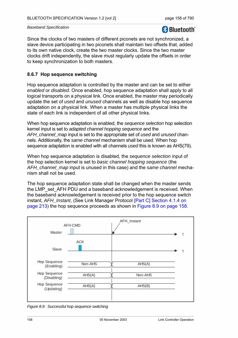
BLUETOOTH SPECIFICATION Version 1.2 [vol 2] page 158 of 790
Baseband Specification
Since the clocks of two masters of different piconets are not synchronized, a slave device participating in two piconets shall maintain two offsets that, added to its own native clock, create the two master clocks. Since the two master clocks drift independently, the slave must regularly update the offsets in order to keep synchronization to both masters.
8.6.7 Hop sequence switching
Hop sequence adaptation is controlled by the master and can be set to either enabled or disabled. Once enabled, hop sequence adaptation shall apply to all logical transports on a physical link. Once enabled, the master may periodically update the set of used and unused channels as well as disable hop sequence adaptation on a physical link. When a master has multiple physical links the state of each link is independent of all other physical links.
When hop sequence adaptation is enabled, the sequence selection hop selection kernel input is set to adapted channel hopping sequence and the AFH_channel_map input is set to the appropriate set of used and unused chan-nels. Additionally, the same channel mechanism shall be used. When hop sequence adaptation is enabled with all channels used this is known as AHS(79).
When hop sequence adaptation is disabled, the sequence selection input of the hop selection kernel is set to basic channel hopping sequence (the AFH_channel_map input is unused in this case) and the same channel mecha-nism shall not be used.
The hop sequence adaptation state shall be changed when the master sends the LMP_set_AFH PDU and a baseband acknowledgement is received. When the baseband acknowledgement is received prior to the hop sequence switch instant, AFH_Instant, (See Link Manager Protocol [Part C] Section 4.1.4 on page 213) the hop sequence proceeds as shown in Figure 8.9 on page 158.
Figure 8.9: Successful hop sequence switching
tMaster
tSlave
AFH_InstantAFH CMD
ACK
Non-AHS AHS(A)
AHS(A) Non-AHS
AHS(A) AHS(B)
Hop Sequence(Enabling)
Hop Sequence(Disabling)
Hop Sequence
(Updating)
158 05 November 2003 Link Controller Operation
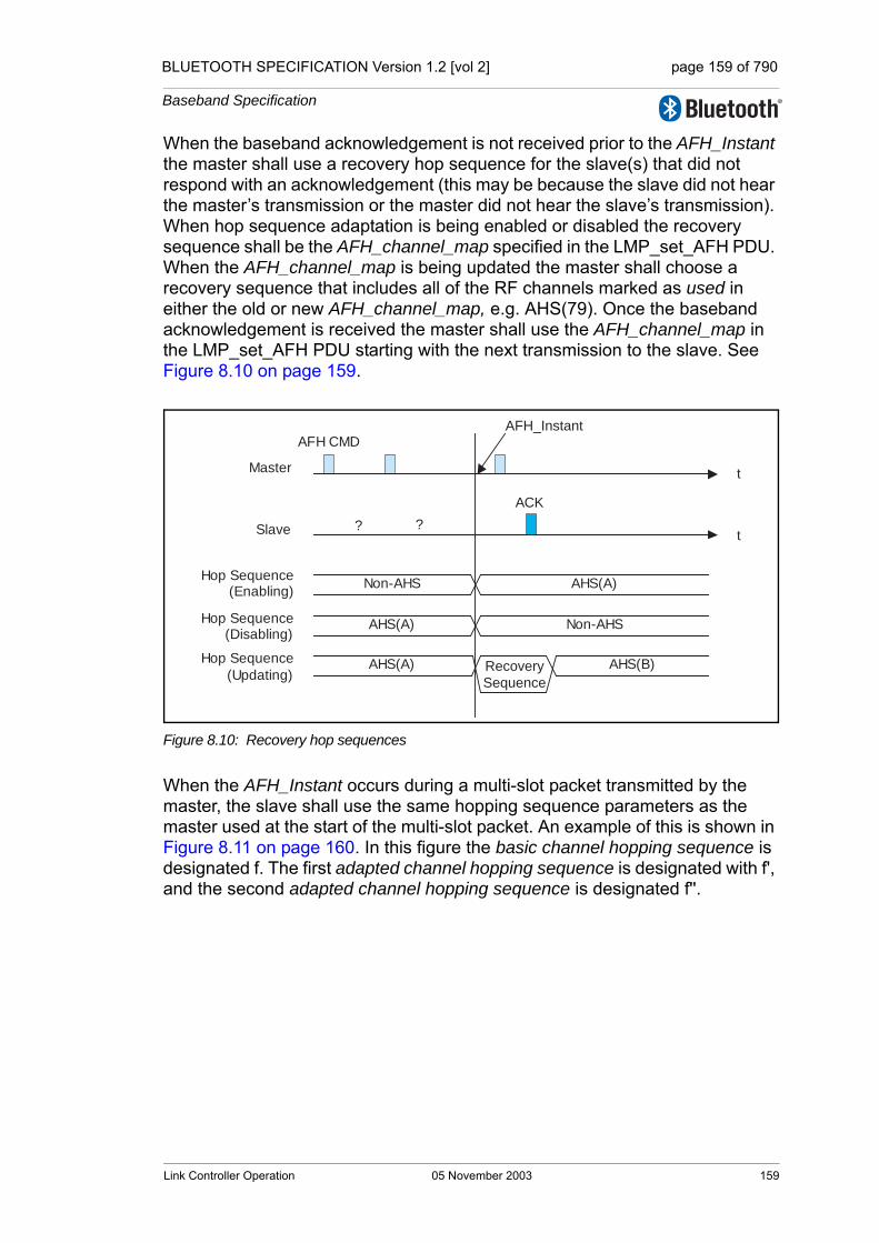
BLUETOOTH SPECIFICATION Version 1.2 [vol 2] page 159 of 790
Baseband Specification
When the baseband acknowledgement is not received prior to the AFH_Instant the master shall use a recovery hop sequence for the slave(s) that did not respond with an acknowledgement (this may be because the slave did not hear the master’s transmission or the master did not hear the slave’s transmission). When hop sequence adaptation is being enabled or disabled the recovery sequence shall be the AFH_channel_map specified in the LMP_set_AFH PDU. When the AFH_channel_map is being updated the master shall choose a recovery sequence that includes all of the RF channels marked as used in either the old or new AFH_channel_map, e.g. AHS(79). Once the baseband acknowledgement is received the master shall use the AFH_channel_map in the LMP_set_AFH PDU starting with the next transmission to the slave. See Figure 8.10 on page 159.
Figure 8.10: Recovery hop sequences
When the AFH_Instant occurs during a multi-slot packet transmitted by the master, the slave shall use the same hopping sequence parameters as the master used at the start of the multi-slot packet. An example of this is shown in Figure 8.11 on page 160. In this figure the basic channel hopping sequence is designated f. The first adapted channel hopping sequence is designated with f', and the second adapted channel hopping sequence is designated f''.
tMaster
tSlave
AFH_InstantAFH CMD
?
Non-AHS AHS(A)
AHS(A) Non-AHS
AHS(A) AHS(B)
Hop Sequence(Enabling)
Hop Sequence(Disabling)
Hop Sequence
(Updating)
?
Recovery
Sequence
ACK
Link Controller Operation 05 November 2003 159
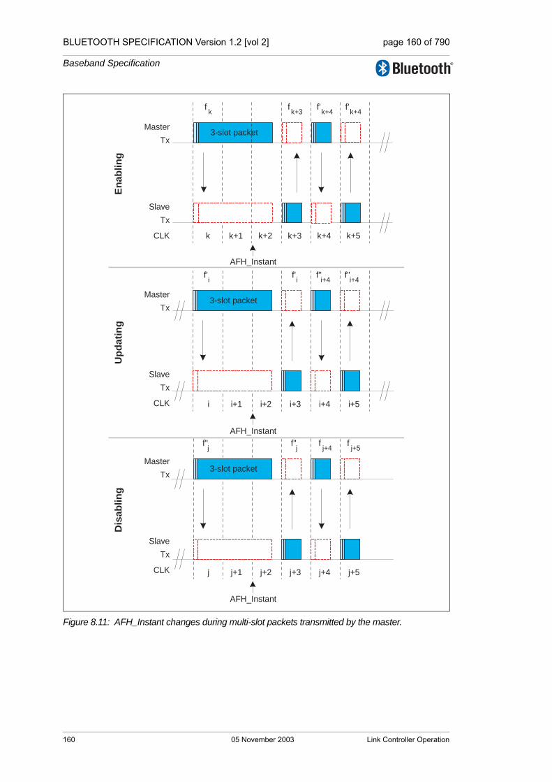
BLUETOOTH SPECIFICATION Version 1.2 [vol 2] page 160 of 790
Baseband Specification
Figure 8.11: AFH_Instant changes during multi-slot packets transmitted by the master.
3-slot packet
fk
fk+3
f'k+4
f'k+4
k k+1 k+2 k+3 k+5k+4CLK
Slave
Tx
Master
Tx
CLK
Slave
Tx
Master
Tx
CLK
Slave
Tx
Master
Tx
En
ab
lin
gU
pd
ati
ng
Dis
ab
lin
g
i i+1 i+2 i+3 i+4 i+5
3-slot packet
f'i
f'i
f"i+4
f"i+4
j j+1 j+2 j+3 j+4 j+5
3-slot packet
f"j
f"j
fj+4
fj+5
AFH_Instant
AFH_Instant
AFH_Instant
160 05 November 2003 Link Controller Operation

BLUETOOTH SPECIFICATION Version 1.2 [vol 2] page 161 of 790
Baseband Specification
8.6.8 Channel classification and channel map selection
RF channels are classified as being unknown, bad or good. These classifica-tions are determined individually by the master and slaves based on local infor-mation (e.g. active or passive channel assessment methods or from the Host via HCI). Information received from other devices via LMP (e.g. an AFH_channel_map from a master or a channel classification report from a slave) shall not be included in a device’s channel classification.
The three possible channel classifications shall be as defined in Table 8.6 on page 161.
A master with AFH enabled physical links shall determine an AFH_channel_map based on any combination of the following information:
• Channel classification from local measurements (e.g. active or passive channel assessment in the Controller), if supported and enabled. The Host may enable or disable local measurements using the HCI Write_AFH_Channel_Classification_Mode command, defined in the HCI Functional Specification [Part E] Section 7.3.58 on page 510 if HCI is present.
• Channel classification information from the Host using the HCI Set_AFH_channel_classification command, defined in the HCI Functional Specification [Part E] Section 7.3.58 on page 510 if HCI is present. Channels classified as bad in the most recent AFH_Host_Channel_Classification shall be marked as unused in the AFH_channel_map.
• Channel classification reports received from slaves in LMP_channel_classification PDUs, defined in the LMP Specification [Part C] Section 4.1.5 on page 216.
Classification Definition
unknown A channel shall be classified as unknown if the channel assessment mea-surements are insufficient to reliably classify the channel, and the channel is not marked as bad in the most recent HCI Set_AFH_Channel_Classification.
bad A channel may be classified as bad if an ACL or synchronous throughput failure measure associated with it has exceeded a threshold (defined by the particular channel assessment algorithm employed).A channel may also be classified as bad if an interference-level measure associated with it, determining the interference level that the link poses upon other systems in the vicinity, has exceeded a threshold (defined by the particular channel assessment algorithm employed).A channel shall be classified as bad when it is marked as bad in the most recent HCI Set_AFH_Channel_Classification command.
good A channel shall be classified as good if it is not either unknown or bad.
Table 8.6: Channel classification descriptions
Link Controller Operation 05 November 2003 161
BLUETOOTH SPECIFICATION Version 1.2 [vol 2] page 162 of 790
Baseband Specification
The algorithm used by the master to combine these information sources and generate the AFH_channel_map is not defined in the specification and will be implementation specific. At no time shall the number of channels used be less than Nmin, defined in Section 2.3.1 on page 63.
If a master that determines that all channels should be used it may keep AFH operation enabled using an AFH_channel_map of 79 used channels, i.e. AHS(79).
8.6.9 Power Management
Features are provided to allow low-power operation. These features are both at the microscopic level when handling the packets, and at the macroscopic level when using certain operation modes.
8.6.9.1 Packet handling
In order to minimize power consumption, packet handling is minimized both at TX and RX sides. At the TX side, power is minimized by only sending useful data. This means that if only link control information needs to be exchanged, NULL packets may be used. No transmission is required if there is no link con-trol information to be sent, or if the transmission would only involve a NAK (NAK is implicit on no reply). If there is data to be sent, the payload length shall be adapted in order to send only the valid data bytes. At the RX side, packet processing takes place in different steps. If no valid access code is found in the search window, the transceiver may return to sleep. If an access code is found, the receiver device shall start to process the packet header. If the HEC fails, the device may return to sleep after the packet header. A valid header indicates if a payload will follow and how many slots are involved.
8.6.9.2 Slot occupancy
As was described in Section 6.5 on page 105, the packet type indicates how many slots a packet may occupy. A slave not addressed in the packet header may go to sleep for the remaining slots the packet occupies. This can be read from the TYPE code.
8.6.9.3 Recommendations for low-power operation
The most common and flexible methods for reducing power consumption are the use of sniff and park. Hold can also be used by repeated negotiation of hold periods.
162 05 November 2003 Link Controller Operation

BLUETOOTH SPECIFICATION Version 1.2 [vol 2] page 163 of 790
Baseband Specification
8.7 SNIFF MODE
In sniff mode, the duty cycle of the slave’s activity in the piconet may be reduced. If a slave is in active mode on an ACL logical transport, it shall listen in every ACL slot to the master traffic, unless that link is being treated as a scatternet link or is absent due to hold mode. With sniff mode, the time slots when a slave is listening are reduced, so the master shall only transmit to a slave in specified time slots. The sniff anchor points are spaced regularly with an interval of Tsniff.
Figure 8.12: Sniff anchor points
The slave listens in master-to-slave transmission slots starting at the sniff anchor point. It shall use the following rules to determine whether to continue listening:
• If fewer than Nsniff attempt master-to-slave transmission slots have elapsed since the sniff anchor point then the slave shall continue listening.
• If the slave has received a packet with a matching LT_ADDR that contains ACL data (DM, DH, DV, or AUX1 packets) in the preceding Nsniff timeout mas-ter-to-slave transmission slots then it shall continue listening.
• If the slave has transmitted a packet containing ACL data (DM, DH, DV, or AUX1 packets) in the preceding Nsniff timeout slave-to-master transmission slots then it shall continue listening.
• If the slave has received any packet with a matching LT_ADDR in the pre-ceding Nsniff timeout master-to-slave transmission slots then it may continue listening.
• A device may override the rules above and stop listening prior to Nsniff timeout or the remaining Nsniff attempt slots if it has activity in another piconet.
It is possible that activity from one sniff timeout may extend to the next sniff anchor point. Any activity from a previous sniff timeout shall not affect activity after the next sniff anchor point. So in the above rules, only the slots since the last sniff anchor point are considered.
Note that Nsniff attempt =1 and Nsniff timeout =0 cause the slave to listen only at the slot beginning at the sniff anchor point, irrespective of packets received from the master.
Nsniff attempt =0 shall not be used.
Sniff interval (Tsniff)
Sniff anchor point Sniff anchor point
master-to-slave
slot
slave-to-master
slot
master-to-slave
slot
slave-to-master
slot
master-to-slave
slot
slave-to-master
slot
Link Controller Operation 05 November 2003 163
BLUETOOTH SPECIFICATION Version 1.2 [vol 2] page 164 of 790
Baseband Specification
Sniff mode only applies to asynchronous logical transports and their associated LT_ADDR. Sniff mode shall not apply to synchronous logical transports, there-fore, both masters and slaves shall still respect the reserved slots and retrans-mission windows of synchronous links.
To enter sniff mode, the master or slave shall issue a sniff command via the LM protocol. This message includes the sniff interval Tsniff and an offset Dsniff. In addition, an initialization flag indicates whether initialization procedure 1 or 2 shall be used. The device shall use initialization 1 when the MSB of the current master clock (CLK27) is 0; it shall use initialization 2 when the MSB of the cur-rent master clock (CLK27) is 1. The slave shall apply the initialization method as indicated by the initialization flag irrespective of its clock bit value CLK27. The sniff anchor point determined by the master and the slave shall be initial-ized on the slots for which the clock satisfies the applicable equation:
CLK27-1 mod Tsniff = Dsniff for initialization 1
(CLK27,CLK26-1) mod Tsniff = Dsniff for initialization 2
this implies that Dsniff must be even
After initialization, the clock value CLK(k+1) for the next sniff anchor point shall be derived by adding the fixed interval Tsniff to the clock value of the current sniff anchor point:
CLK(k+1) = CLK(k) + Tsniff
8.7.1 Sniff Transition Mode
Sniff transition mode is a special mode which is used during the transition between Sniff and active mode. It is required because during this transition it is unclear which mode (Sniff or Active) the slave is in and it is necessary to ensure that the slave is polled correctly regardless of which mode it is in.
In sniff transition mode the master shall maintain the active mode poll interval in case the slave is in active mode. In addition the master shall poll the slave at least once in the sniff attempt transmit slots starting at each sniff instant: note that this transmission counts for the active mode polling as well. The master must use its high power accurate clock when in Sniff Transition Mode.
The precise circumstances under which the master enters Sniff Transition Mode are defined in [Part C] Section 4.5.3.1 on page 254.
164 05 November 2003 Link Controller Operation
BLUETOOTH SPECIFICATION Version 1.2 [vol 2] page 165 of 790
Baseband Specification
8.8 HOLD MODE
During the CONNECTION state, the ACL logical transport to a slave can be put in a hold mode. In hold mode the slave temporarily shall not support ACL packets on the channel. Any synchronous packet during reserved synchonous slots (from SCO and eSCO links) shall be supported. With the hold mode, capacity can be made free to do other things like scanning, paging, inquiring, or attending another piconet. The device in hold mode can also enter a low-power sleep mode. During hold mode, the slave device keeps its logical trans-port address(es) (LT_ADDR).
Prior to entering hold mode, master and slave agree on the time duration the slave remains in hold mode. A timer shall be initialized with the holdTO value. When the timer is expired, the slave shall wake up, synchronize to the traffic on the channel and will wait for further master transmissions.
8.9 PARK STATE
When a slave does not need to participate on the piconet channel, but still needs to remain synchronized to the channel, it can enter PARK state. PARK state is a state with very little activity in the slave. In the PARK state, the slave shall give up its logical transport address LT_ADDR. Instead, it shall receive two new addresses to be used in the PARK state• PM_ADDR: 8-bit Parked Member Address• AR_ADDR: 8-bit Access Request Address
The PM_ADDR distinguishes a parked slave from the other parked slaves. This address may be used in the master-initiated unpark procedure. In addition to the PM_ADDR, a parked slave may also be unparked by its 48-bit BD_ADDR. The all-zero PM_ADDR is a reserved address: if a parked device has the all-zero PM_ADDR it can only be unparked by the BD_ADDR. In that case, the PM_ADDR has no meaning. The AR_ADDR shall be used by the slave in the slave-initiated unpark procedure. All messages sent to the parked slaves are carried by broadcast packets.
The parked slave wakes up at regular intervals to listen to the channel in order to re-synchronize and to check for broadcast messages. To support the syn-chronization and channel access of the parked slaves, the master supports a beacon train described in the next section. The beacon structure is communi-cated to the slave when it is parked. When the beacon structure changes, the parked slaves are updated through broadcast messages.
The master shall maintain separate non-overlapping park beacon structures for each hop sequence. The beacon structures shall not overlap either their bea-con slots or access windows.
In addition for using it for low power consumption, park is used to connect more than seven slaves to a single master. At any one time, only seven slaves can be in the CONNECTION state. However, by swapping active and parked slaves out respectively in the piconet, the number of slaves can be much larger (255 if the PM_ADDR is used, and an arbitrarily large number if the BD_ADDR is used).
Link Controller Operation 05 November 2003 165

BLUETOOTH SPECIFICATION Version 1.2 [vol 2] page 166 of 790
Baseband Specification
8.9.1 Beacon train
To support parked slaves, the master establishes a beacon train when one or more slaves are parked. The beacon train consists of one beacon slot or a train of equidistant beacon slots which is transmitted periodically with a constant time interval. The beacon train is illustrated in Figure 8.13 on page 167. A train of NB (NB ≥ 1) beacon slots is defined with an interval of TB slots. The beacon slots in the train are separated by ∆B . The start of the first beacon slot is referred to as the beacon instant and serves as the beacon timing reference. The beacon parameters NB and TB are chosen such that there are sufficient beacon slots for a parked slave to synchronize to during a certain time window in an error-prone environment.
When parked, the slave shall receive the beacon parameters through an LMP command. In addition, the timing of the beacon instant is indicated through the offset DB. As with the SCO logical transport (see Section 8.6.2 on page 150), two initialization procedures 1 or 2 are used. The master shall use initialization 1 when the MSB of the current master clock (CLK27) is 0; it shall use initializa-tion 2 when the MSB of the current master clock (CLK27) is 1. The chosen ini-tialization procedure shall also be carried by an initialization flag in the LMP command. The slave shall apply the initialization method as indicated by the initialization flag irrespective of its clock bit CLK27. The master-to-slave slot positioned at the beacon instant shall be initialized on the slots for which the clock satisfies the applicable equation:
CLK27-1 mod TB = DB for initialization 1
(CLK27,CLK26-1) mod TB = DB for initialization 2
this implies that DB will be even
After initialization, the clock value CLK(k+1) for the next beacon instant shall be derived by adding the fixed interval TB to the clock value of the current beacon instant:
CLK(k+1) = CLK(k) + TB
The beacon train serves four purposes:
1. transmission of master-to-slave packets which the parked slaves can use for re-synchronization
2. carrying messages to the parked slaves to change the beacon parameters
3. carrying general broadcast messages to the parked slaves
4. unparking of one or more parked slaves
166 05 November 2003 Link Controller Operation

BLUETOOTH SPECIFICATION Version 1.2 [vol 2] page 167 of 790
Baseband Specification
Since a slave can synchronize to any packet which is preceded by the proper channel access code, the packets carried on the beacon slots do not have to contain specific broadcast packets for parked slaves to be able to synchronize; any packet may be used. The only requirement placed on the beacon slots is that there is a master-to-slave transmission present on the hopping sequence associated with the park structure. If there is no information to be sent, NULL packets may be transmitted by the master. If there is indeed broadcast informa-tion to be sent to the parked slaves, the first packet of the broadcast message shall be repeated in every beacon slot of the beacon train. However, synchro-nous traffic in the synchronous reserved slots may interrupt the beacon transmis-sion if it is on the same hopping sequence as the parked slaves. The master shall configure its park beacon structure so that reserved slots of synchronous logical transports do not cause slaves to miss synchronisation on a beacon slot. For example, a master that has active slaves using AHS, and parked slaves using Non-AHS shall ensure that the Park beacons cannot be interrupted by AHS synchronous reserved slots.
Figure 8.13: General beacon train format
The master can place parked slaves in any of the AFH operating modes, but shall ensure that all parked slaves use the same hop sequence. Masters should use AHS(79) or AHS when all the slaves in the Piconet are AFH capable.
A master that switches a slave between AFH enabled, AFH disabled or AHS(79) operation shall ensure that the AFH_Instant occurs before transmis-sion of the beacon train using this hop sequence.
The master communicates with parked slaves using broadcast messages. Since these messages can be time - critical, an ongoing repetition train of broadcast message may be prematurely aborted by broadcast information des-tined to parked slaves in beacon slots and in access windows (see Section 8.9.2 on page 168).
1 2 NB
TB
∆B
1 2 NB
beacon instant
beacon slots
t
Link Controller Operation 05 November 2003 167
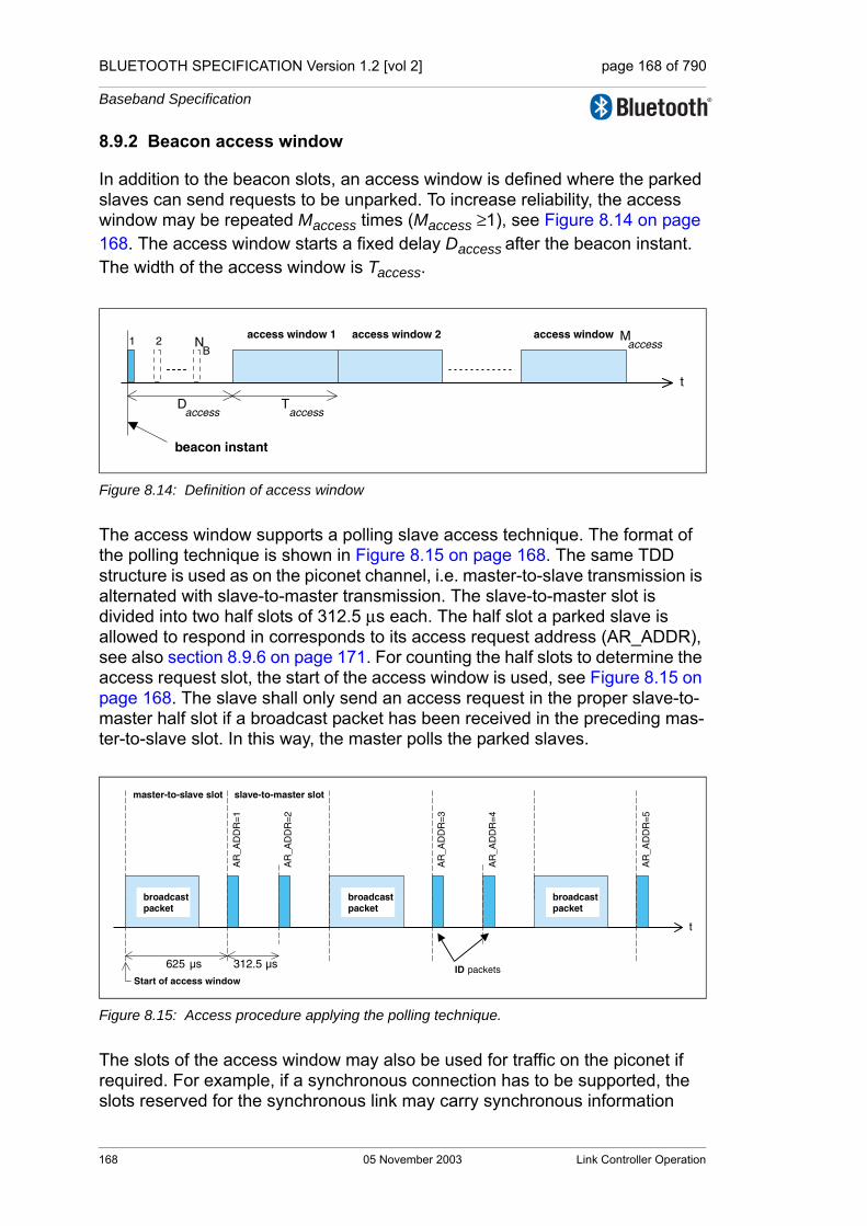
BLUETOOTH SPECIFICATION Version 1.2 [vol 2] page 168 of 790
Baseband Specification
8.9.2 Beacon access window
In addition to the beacon slots, an access window is defined where the parked slaves can send requests to be unparked. To increase reliability, the access window may be repeated Maccess times (Maccess ≥1), see Figure 8.14 on page 168. The access window starts a fixed delay Daccess after the beacon instant. The width of the access window is Taccess.
Figure 8.14: Definition of access window
The access window supports a polling slave access technique. The format of the polling technique is shown in Figure 8.15 on page 168. The same TDD structure is used as on the piconet channel, i.e. master-to-slave transmission is alternated with slave-to-master transmission. The slave-to-master slot is divided into two half slots of 312.5 µs each. The half slot a parked slave is allowed to respond in corresponds to its access request address (AR_ADDR), see also section 8.9.6 on page 171. For counting the half slots to determine the access request slot, the start of the access window is used, see Figure 8.15 on page 168. The slave shall only send an access request in the proper slave-to-master half slot if a broadcast packet has been received in the preceding mas-ter-to-slave slot. In this way, the master polls the parked slaves.
Figure 8.15: Access procedure applying the polling technique.
The slots of the access window may also be used for traffic on the piconet if required. For example, if a synchronous connection has to be supported, the slots reserved for the synchronous link may carry synchronous information
1 2 NB
Daccess
Taccess
t
access window 1 access window 2 access window Maccess
beacon instant
625 µs
master-to-slave slot
Start of access window
AR
_AD
DR
=1
AR
_AD
DR
=2
AR
_AD
DR
=3
AR
_AD
DR
=4
AR
_AD
DR
=5
312.5 µs
broadcastpacket
broadcastpacket
broadcastpacket
slave-to-master slot
t
ID packets
168 05 November 2003 Link Controller Operation

BLUETOOTH SPECIFICATION Version 1.2 [vol 2] page 169 of 790
Baseband Specification
instead of being used for access requests, i.e. if the master-to-slave slot in the access window contains a packet different from a broadcast packet, the follow-ing slave-to-master slot shall not be used for slave access requests. If the mas-ter transmits a broadcast packet in the access window then it shall use the hop sequence associated with the park structure. Slots in the access window not affected by piconet traffic may still be used according to the defined access structure, (an example is shown in Figure 8.16 on page 169) the access proce-dure shall be continued as if no interruption had taken place.
When the slave is parked, the master shall indicate what type of access scheme will be used. For the polling scheme, the number of slave-to-master access slots Nacc_slot is indicated.
Figure 8.16: Disturbance of access window by SCO traffic
By default, the access window is always present. However, its activation depends on the master sending broadcast messages to the slave at the appro-priate slots in the access window. A flag in a broadcast LMP message within the beacon slots may indicate that the access window(s) belonging to this instant will not be activated. This prevents unnecessary scanning of parked slaves that want to request access.
8.9.3 Parked slave synchronization
Parked slaves wake up periodically to re-synchronize to the channel. Any packet exchanged on the channel can be used for synchronization. Since mas-ter transmission is mandatory on the beacon slots, parked slaves will use the beacon train to re-synchronize. A parked slave may wake-up at the beacon instant to read the packet sent on the first beacon slot. If this fails, it may retry on the next beacon slot in the beacon train; in total, there are NB opportunities per beacon instant to re-synchronize. During the search, the slave may increase its search window, see also Section 2.2.5.2 on page 62. The separa-tion between the beacon slots in the beacon train ∆B shall be chosen such that consecutive search windows will not overlap.
The parked slave may not wake up at every beacon instant. Instead, a sleep interval may be applied which is longer than the beacon interval TB, see Figure 8.17 on page 170. The slave sleep window shall be a multiple NB_sleep of TB.
625 µs
master-to-slave slot
AR
_AD
DR
=1
AR
_AD
DR
=2
AR
_AD
DR
=5
312.5 µs
broadcastpacket
master SCOpacket
broadcastpacket
slave-to-master slot
t
slave SCOpacket
Link Controller Operation 05 November 2003 169
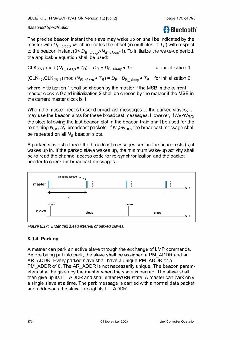
BLUETOOTH SPECIFICATION Version 1.2 [vol 2] page 170 of 790
Baseband Specification
The precise beacon instant the slave may wake up on shall be indicated by the master with DB_sleep which indicates the offset (in multiples of TB) with respect to the beacon instant (0< DB_sleep<NB_sleep-1). To initialize the wake-up period, the applicable equation shall be used:
CLK27-1 mod (NB_sleep • TB) = DB + DB_sleep • TB for initialization 1
(CLK27,CLK26-1) mod (NB_sleep • TB) = DB+ DB_sleep • TB for initialization 2
where initialization 1 shall be chosen by the master if the MSB in the current master clock is 0 and initialization 2 shall be chosen by the master if the MSB in the current master clock is 1.
When the master needs to send broadcast messages to the parked slaves, it may use the beacon slots for these broadcast messages. However, if NB<NBC, the slots following the last beacon slot in the beacon train shall be used for the remaining NBC-NB broadcast packets. If NB>NBC, the broadcast message shall be repeated on all NB beacon slots.
A parked slave shall read the broadcast messages sent in the beacon slot(s) it wakes up in. If the parked slave wakes up, the minimum wake-up activity shall be to read the channel access code for re-synchronization and the packet header to check for broadcast messages.
Figure 8.17: Extended sleep interval of parked slaves.
8.9.4 Parking
A master can park an active slave through the exchange of LMP commands. Before being put into park, the slave shall be assigned a PM_ADDR and an AR_ADDR. Every parked slave shall have a unique PM_ADDR or a PM_ADDR of 0. The AR_ADDR is not necessarily unique. The beacon param-eters shall be given by the master when the slave is parked. The slave shall then give up its LT_ADDR and shall enter PARK state. A master can park only a single slave at a time. The park message is carried with a normal data packet and addresses the slave through its LT_ADDR.
TB
beacon instant
t
t
master
slave
scan scan
sleep sleep
170 05 November 2003 Link Controller Operation
BLUETOOTH SPECIFICATION Version 1.2 [vol 2] page 171 of 790
Baseband Specification
8.9.5 Master-initiated unparking
The master can unpark a parked slave by sending a dedicated LMP unpark command including the parked slave’s address. This message shall be sent in a broadcast packet on the beacon slots. The master shall use either the slave’s PM_ADDR, or its BD_ADDR. The message also includes the logical transport address LT_ADDR the slave shall use after it has re-entered the piconet. The unpark message may include a number of slave addresses so that multiple slaves may be unparked simultaneously. For each slave, a different LT_ADDR shall be assigned.
After having received the unpark message, the parked slave matching the PM_ADDR or BD_ADDR shall leave the PARK state and enter the CONNEC-TION state. It shall keep listening to the master until it is addressed by the mas-ter through its LT_ADDR. The first packet sent by the master shall be a POLL packet. The return packet in response to the POLL packet confirms that the slave has been unparked. If no response packets from the slave is received for newconnectionTO number of slots after the end of beacon repetition period, the master shall unpark the slave again. The master shall use the same LT_ADDR on each unpark attempt until it has received a link supervision time-out for that slave or the unpark has completed successfully. If the slave does not receive the POLL packet for newconnectionTO number of slots after the end of beacon repetition period, it shall return to park, with the same beacon parameters. After confirming that the slave is in the CONNECTION state, the master decides in which mode the slave will continue.
When a device is unparked, the SEQN bit for the link shall be reset to 1 on both the master and the slave (see Section 7.6.2.1 on page 128).
8.9.6 Slave-initiated unparking
A slave can request access to the channel through the access window defined in section 8.9.2 on page 168. As shown in Figure 8.15 on page 168, the access window includes several slave-to-master half slots where the slave may send an access request message. The specific half slot the slave is allowed to respond in, corresponds to its access request address (AR_ADDR) which it received when it was parked. The order of the half slots (in Figure 8.15 the AR_ADDR numbers linearly increase from 1 to 5) is not fixed: an LMP com-mand sent in the beacon slots may reconfigure the access window. When a slave desires access to the channel, it shall send an access request message in the proper slave-to-master half slot. The access request message of the slave is the ID packet containing the device access code (DAC) of the master (which is the channel access code without the trailer). The parked slave shall only transmit an access request message in the half slot, when in the preced-ing master-to-slave slot a broadcast packet has been received. This broadcast message may contain any kind of broadcast information not necessarily related to the parked slave(s). If no broadcast information is available, a broadcast NULL or broadcast POLL packet shall be sent.
Link Controller Operation 05 November 2003 171

BLUETOOTH SPECIFICATION Version 1.2 [vol 2] page 172 of 790
Baseband Specification
After having sent an access request, the parked slave shall listen for an unpark message from the master. As long as no unpark message is received, the slave shall repeat the access requests in the subsequent access windows. After the last access window (there are Maccess windows in total, see Section 8.9.2 on page 168), the parked slave shall listen for an additional Npoll time slots for an unpark message. If no unpark message is received within Npoll slots after the end of the last access window, the slave may return to sleep and retry an access attempt after the next beacon instant.
After having received the unpark message, the parked slave matching the PM_ADDR or BD_ADDR shall leave the PARK state and enter the CONNEC-TION state. It shall keep listening to the master until it is addressed by the master through its LT_ADDR. The first packet sent by the master shall be a POLL packet. The return packet in response to the POLL packet confirms that the slave has been unparked. After confirming that the slave is in the CONNECTION state, the master decides in which mode the slave will continue. If no response packet from the slave is received for newconnectionTO number of slots after Npoll slots after the end of the last access window, the master shall send the unpark mes-sage to the slave again. If the slave does not receive the POLL packet for new-connectionTO number of slots after Npoll slots after the end of the last access window, it shall return to park, with the same beacon parameters.
When a device is unparked, the SEQN bit for the link shall be reset to 1 on both the master and the slave (see Section 7.6.2.1 on page 128).
8.9.7 Broadcast scan window
In the beacon train, the master can support broadcast messages to the parked slaves. However, it may extend its broadcast capacity by indicating to the parked slaves that more broadcast information is following after the beacon train. This is achieved by an LMP command ordering the parked slaves (as well as the active slaves) to listen to the channel for broadcast messages during a limited time win-dow. This time window starts at the beacon instant and continues for the period indicated in the LMP command sent in the beacon train.
8.9.8 Polling in the park state
In the PARK state, parked slaves may send access requests in the access win-dow provided a broadcast packet is received in the preceding master-to-slave slot. Slaves in the CONNECTION state shall not send in the slave-to-master slots following the broadcast packet, since they are only allowed to send if addressed specifically.
172 05 November 2003 Link Controller Operation

BLUETOOTH SPECIFICATION Version 1.2 [vol 2] page 173 of 790
Baseband Specification
9 AUDIO
On the air-interface, either a 64 kb/s log PCM (Pulse Code Modulation) format (A-law or µ-law) may be used, or a 64 kb/s CVSD (Continuous Variable Slope Delta Modulation) may be used. The latter format applies an adaptive delta modulation algorithm with syllabic companding.
The voice coding on the line interface is designed to have a quality equal to or better than the quality of 64 kb/s log PCM.
Table 9.1 on page 173 summarizes the voice coding schemes supported on the air interface. The appropriate voice coding scheme is selected after negoti-ations between the Link Managers.
9.1 LOG PCM CODEC
Since the synchronous logical transports on the air-interface can support a 64 kb/s information stream, a 64 kb/s log PCM traffic can be used for transmis-sion. Either A-law or µ-law compression may be applied. In the event that the line interface uses A-law and the air interface uses µ-law or vice versa, a con-version from A-law to µ-law shall be performed. The compression method shall follow ITU-T recommendations G. 711.
9.2 CVSD CODEC
A more robust format for voice over the air interface is delta modulation. This modulation scheme follows the waveform where the output bits indicate whether the prediction value is smaller or larger then the input waveform. To reduce slope overload effects, syllabic companding is applied: the step size is adapted according to the average signal slope. The input to the CVSD encoder shall be 64 ksamples/s linear PCM (typically 16 bits, but actual value is imple-mentation specific). Block diagrams of the CVSD encoder and CVSD decoder are shown in Figure 9.1 on page 174, Figure 9.2 on page 174 and Figure 9.3 on page 174. The system shall be clocked at 64 kHz.
Voice Codecs
linear CVSD
8-bit logarithmicA-law
µ-law
Table 9.1: Voice coding schemes supported on the air interface.
Audio 05 November 2003 173

BLUETOOTH SPECIFICATION Version 1.2 [vol 2] page 174 of 790
Baseband Specification
Figure 9.1: Block diagram of CVSD encoder with syllabic companding.
Figure 9.2: Block diagram of CVSD decoder with syllabic companding.
Figure 9.3: Accumulator procedure.
Let for , otherwise . On air these numbers shall be represented by the sign bit; i.e. negative numbers are mapped on “1” and posi-tive numbers are mapped on “0”.
Denote the CVSD encoder output bit , the encoder input , the accumu-lator contents , and the step size . Furthermore, let h be the decay fac-tor for the accumulator, let β denote the decay factor for the step size, and, let α be the syllabic companding parameter. The latter parameter monitors the slope by considering the K most recent output bits
Let
(EQ 12)
Then, the CVSD encoder internal state shall be updated according to the fol-lowing set of equations:
Accumulator Step sizecontrol
b k( )
δ k( )
x k 1–( )
+-
x k( )
AccumulatorStep sizecontrol δ k( )
b k( )
x k 1–( )
D Sat.⊕⊗ ⊗
b k( )
δ k( )
h
y k( ) y k 1–( )y k 1–( )x k 1–( )
sgn x( ) 1= x 0≥ sgn x( ) 1–=
b k( ) x k( )y k( ) δ k( )
x k( ) hy k( ).=
174 05 November 2003 Audio
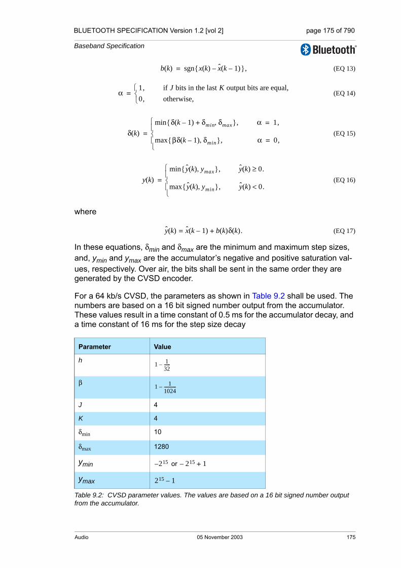
BLUETOOTH SPECIFICATION Version 1.2 [vol 2] page 175 of 790
Baseband Specification
(EQ 13)
(EQ 14)
(EQ 15)
(EQ 16)
where
(EQ 17)
In these equations, δmin and δmax are the minimum and maximum step sizes, and, ymin and ymax are the accumulator’s negative and positive saturation val-ues, respectively. Over air, the bits shall be sent in the same order they are generated by the CVSD encoder.
For a 64 kb/s CVSD, the parameters as shown in Table 9.2 shall be used. The numbers are based on a 16 bit signed number output from the accumulator. These values result in a time constant of 0.5 ms for the accumulator decay, and a time constant of 16 ms for the step size decay
Parameter Value
h
β
J 4
K 4
δmin 10
δmax 1280
ymin or
ymax
Table 9.2: CVSD parameter values. The values are based on a 16 bit signed number output from the accumulator.
b k( ) sgn x k( ) x k 1–( )–{ },=
α1, if J bits in the last K output bits are equal,0, otherwise,⎩
⎨⎧
=
δ k( )δ k 1–( ) δmin+ δmax,{ },min α 1,=
βδ k 1–( ) δmin,{ }max , α 0,=⎩⎪⎨⎪⎧
=
y k( )y k( ) ymax,{ },min y k( ) 0.≥
y k( ) ymin,{ },max y k( ) 0.<⎩⎪⎨⎪⎧
=
y k( ) x k 1–( ) b k( )δ k( )+= .
1 132------–
1 11024------------–
215– 215– 1+
215 1–
Audio 05 November 2003 175

BLUETOOTH SPECIFICATION Version 1.2 [vol 2] page 176 of 790
Baseband Specification
9.3 ERROR HANDLING
In the DV, HV3,EV3 and EV5 packets, the voice is not protected by FEC. The quality of the voice in an error-prone environment then depends on the robust-ness of the voice coding scheme and, in the case of eSCO, the retransmission scheme. CVSD, in particular, is rather insensitive to random bit errors, which are experienced as white background noise. However, when a packet is rejected because either the channel access code, the HEC test was unsuc-cessful, or the CRC has failed, measures have to be taken to “fill” in the lost speech segment.
The voice payload in the HV2 and EV4 packets are protected by a 2/3 rate FEC. For errors that are detected but cannot be corrected, the receiver should try to minimize the audible effects. For instance, from the 15-bit FEC segment with uncorrected errors, the 10-bit information part as found before the FEC decoder should be used. The HV1 packet is protected by a 3 bit repetition FEC. For this code, the decoding scheme will always assume zero or one-bit errors. Thus, there exist no detectable but uncorrectable error events for HV1 packets.
9.4 GENERAL AUDIO REQUIREMENTS
9.4.1 Signal levels
For A-law and µ-law log-PCM encoded signals the requirements on signal lev-els shall follow the ITU-T recommendation G.711.
Full swing at the 16 bit linear PCM interface to the CVSD encoder is defined to be 3 dBm0.
9.4.2 CVSD audio quality
For Bluetooth audio quality the requirements are put on the transmitter side. The 64 ksamples/s linear PCM input signal should have negligible spectral power density above 4 kHz. The power spectral density in the 4-32 kHz band of the decoded signal at the 64 ksample/s linear PCM output, should be more than 20 dB below the maximum in the 0-4 kHz range.
176 05 November 2003 Audio

BLUETOOTH SPECIFICATION Version 1.2 [vol 2] page 177 of 790
Baseband Specification
10 LIST OF FIGURES
Figure 1.1: Piconets with a single slave operation (a), a multi-slave operation (b) and a scatternet operation (c). .............................................53
Figure 1.2: Standard packet format. ............................................................53Figure 1.3: Bluetooth clock. .........................................................................54Figure 1.4: Format of BD_ADDR. ................................................................55
Figure 2.1: Multi-slot packets ......................................................................59Figure 2.2: Derivation of CLK in master (a) and in slave (b). .....................60Figure 2.3: RX/TX cycle of master transceiver in normal mode for single-slot
packets. .....................................................................................61Figure 2.4: RX/TX cycle of slave transceiver in normal mode for single-slot
packets. .....................................................................................62Figure 2.5: RX timing of slave returning from hold mode. ...........................63Figure 2.6: Derivation of CLKE. ...................................................................64Figure 2.7: RX/TX cycle of transceiver in PAGE mode. ..............................65Figure 2.8: Timing of page response packets on successful page in first half
slot ............................................................................................66Figure 2.9: Timing of page response packets on successful page in second
half slot ......................................................................................67Figure 2.10: Timing of inquiry response packet on successful inquiry in first
half slot ......................................................................................69Figure 2.11: Timing of inquiry response packet on successful inquiry in
second half slot .........................................................................69Figure 2.12: General block diagram of hop selection scheme. .....................71Figure 2.13: Hop selection scheme in CONNECTION state. ........................72Figure 2.14: Single- and multi-slot packets. ..................................................73Figure 2.15: Example of the same channel mechanism. ..............................73Figure 2.16: Block diagram of the basic hop selection kernel for the hop
system. ......................................................................................74Figure 2.17: XOR operation for the hop system. ...........................................75Figure 2.18: Permutation operation for the hop system. ...............................76Figure 2.19: Butterfly implementation. ...........................................................76Figure 2.20: Block diagram of adaptive hop selection mechanism ..............78
Figure 4.1: Functional diagram of TX buffering. ..........................................87Figure 4.2: Functional diagram of RX buffering ...........................................91
Figure 6.1: General packet format. ..............................................................97Figure 6.2: Access code format ...................................................................98Figure 6.3: Preamble ...................................................................................99Figure 6.4: Construction of the sync word. ................................................100
List of Figures 05 November 2003 177

BLUETOOTH SPECIFICATION Version 1.2 [vol 2] page 178 of 790
Baseband Specification
Figure 6.5: LFSR and the starting state to generate . ...............................102Figure 6.6: Trailer in CAC when MSB of sync word is 0 (a), and when MSB
of sync word is 1 (b). ...............................................................102Figure 6.7: Header format. ........................................................................103Figure 6.8: Format of the FHS payload. ....................................................107Figure 6.9: DV packet format ....................................................................109Figure 6.10: Payload header format for single-slot ACL packets. ............... 113Figure 6.11: Payload header format for multi-slot ACL packets. ................. 113
Figure 7.1: Header bit processes. ............................................................. 117Figure 7.2: Payload bit processes. ............................................................ 117Figure 7.3: The LFSR circuit generating the HEC. ................................... 118Figure 7.4: Initial state of the HEC generating circuit. ............................... 119Figure 7.5: HEC generation and checking. ............................................... 119Figure 7.6: The LFSR circuit generating the CRC. ...................................120Figure 7.7: Initial state of the CRC generating circuit. ...............................120Figure 7.8: CRC generation and checking. ...............................................120Figure 7.9: Data whitening LFSR. .............................................................121Figure 7.10: Bit-repetition encoding scheme. .............................................122Figure 7.11: LFSR generating the (15,10) shortened Hamming code. .......123Figure 7.12: Stage 1 of the receive protocol for determining the ARQN bit. 125Figure 7.13: Stage 2 (ACL) of the receive protocol for determining the ARQN
bit. ..........................................................................................126Figure 7.14: Stage 2 (eSCO) of the receive protocol for determining the
ARQN bit. ...............................................................................127Figure 7.15: Transmit filtering for packets with CRC. ..................................128Figure 7.16: Broadcast repetition scheme ..................................................131
Figure 8.1: State diagram of link controller. ...............................................133Figure 8.2: Conventional page (a), page while one synchronous link present
(b), page while two synchronous links present (c). .................138Figure 8.3: Messaging at initial connection when slave responds to first page
message. ................................................................................140Figure 8.4: Messaging at initial connection when slave responds to second
page message. .......................................................................140Figure 8.5: Connection state. ...................................................................148Figure 8.6: RX/TX timing in multi-slave configuration ...............................149Figure 8.7: eSCO Window Details for Single-Slot Packets .......................153Figure 8.8: eSCO Window Details for Asymmetric Traffic .........................153Figure 8.9: Successful hop sequence switching .......................................158Figure 8.10: Recovery hop sequences .......................................................159Figure 8.11: AFH_Instant changes during multi-slot packets transmitted by
the master. ..............................................................................160
178 05 November 2003 List of Figures
BLUETOOTH SPECIFICATION Version 1.2 [vol 2] page 179 of 790
Baseband Specification
Figure 8.12: Sniff anchor points ..................................................................163Figure 8.13: General beacon train format ...................................................167Figure 8.14: Definition of access window ....................................................168Figure 8.15: Access procedure applying the polling technique. ..................168Figure 8.16: Disturbance of access window by SCO traffic ........................169Figure 8.17: Extended sleep interval of parked slaves. ...............................170
Figure 9.1: Block diagram of CVSD encoder with syllabic companding. ...174Figure 9.2: Block diagram of CVSD decoder with syllabic companding. ...174Figure 9.3: Accumulator procedure. ..........................................................174
Appendix A: General Audio RequirementsFigure SLR measurement set-up. ......................................................183Figure RLR measurement set-up. ......................................................183Figure Plot of recommended frequency mask for Bluetooth. The GSM
send frequency mask is given for comparison (dotted line) 184
Appendix C: Recommendations for AFH Operation in Park, Hold and Sniff
Figure Timing constraint on AFH_Instant with slaves in park, hold and sniff .........................................................................................188
List of Figures 05 November 2003 179

BLUETOOTH SPECIFICATION Version 1.2 [vol 2] page 180 of 790
Baseband Specification
180 05 November 2003 List of Figures

BLUETOOTH SPECIFICATION Version 1.2 [vol 2] page 181 of 790
Baseband Specification
11 LIST OF TABLES
Table 2.1: Control of the butterflies for the hop system ..............................75Table 2.2: Control for hop system. ..............................................................79
Table 6.1: Summary of access code types. ................................................98Table 6.2: Packets defined for synchronous and asynchronous logical
transport types. ........................................................................105Table 6.3: Description of the FHS payload ...............................................107Table 6.4: Contents of SR field .................................................................108Table 6.5: Contents of page scan mode field............................................108Table 6.6: Logical link LLID field contents................................................113Table 6.7: Use of payload header flow bit on the logical links. .................115Table 6.8: Link control packets .................................................................116Table 6.9: ACL packets.............................................................................116Table 6.10: Synchronous packets...............................................................116
Table 8.1: Relationship between scan interval, and paging modes R0, R1 and R2. ....................................................................................135
Table 8.2: Relationship between train repetition, and paging modes R0, R1 and R2 when synchronous links are present......................138
Table 8.3: Initial messaging during start-up. ............................................139Table 8.4: Increase of train repetition when synchronous links are
present. ....................................................................................146Table 8.5: Messaging during inquiry routines. .........................................147Table 8.6: Channel classification descriptions ..........................................161
Table 9.1: Voice coding schemes supported on the air interface..............173Table 9.2: CVSD parameter values. The values are based on a 16 bit
signed number output from the accumulator............................175
Appendix A: General Audio RecommendationsTable Recommended Frequency Mask for Bluetooth........................184
12 APPENDIX
List of Tables 05 November 2003 181

BLUETOOTH SPECIFICATION Version 1.2 [vol 2] page 182 of 790
Baseband Specification
APPENDIX A: GENERAL AUDIO RECOMMENDATIONS
MAXIMUM SOUND PRESSURE
It is the sole responsibility of each manufacturer to design their audio products in a safe way with regards to injury to the human ear. The Bluetooth Specifica-tion doesn’t specify maximum sound pressure from an audio device.
OTHER TELEPHONY NETWORK REQUIREMENTS
It is the sole responsibility of each manufacturer to design the Bluetooth audio product so that it meets the regulatory requirements of all telephony networks that it may be connected to.
AUDIO LEVELS FOR BLUETOOTH
Audio levels shall be calculated as Send Loudness Rating, SLR, and Receive Loudness Rating, RLR. The calculation methods are specified in ITU-T Recommendation P.79.
The physical test set-up for Handsets and Headsets is described in ITU-T Recommendation P.51 and P.57
The physical test set-up for speakerphones and “Vehicle handsfree systems” is specified in ITU-T Recommendation P.34.
A general equation for computation of loudness rating (LR) for telephone sets is given by ITU-T recommendations P.79 and is given by
(EQ 18)
where
m is a constant (~ 0.2).
wi = weighting coefficient (different for the various LRs).
Si = the sensitivity at frequency Fi, of the electro-acoustic path
N1,N2, consecutive filter bank numbers (Art. Index: 200-4000 Hz)
(EQ 18) on page 182 is used for calculating the (SLR) according to Figure on page 183, and (RLR) according to Figure on page 183. When calculating LRs one must only include those parts of the frequency band where an actual signal transmission can occur in order to ensure that the additive property of LRs is retained. Therefore ITU-T P.79 uses only the frequency band 200-4000 Hz in LR computations.
LR 10m------ 10
m si wi–( ) 10⁄
i N1=
N2
∑⎝ ⎠⎜ ⎟⎜ ⎟⎛ ⎞
log10 ,–=
182 05 November 2003 Appendix

BLUETOOTH SPECIFICATION Version 1.2 [vol 2] page 183 of 790
Baseband Specification
MICROPHONE PATH
SLR measurement model
SLR measurement set-up.
LOUDSPEAKER PATH
RLR measurement model
RLR measurement set-up.
BLUETOOTH VOICE INTERFACEThe specification for the Bluetooth voice interface should follow in the first place the ITU-T Recommendations P.79, which specifies the loudness ratings for telephone sets. These recommendations give general guidelines and spe-cific algorithms used for calculating the loudness ratings of the audio signal with respect to Ear Reference Point (ERP).
For Bluetooth voice interface to the different cellular system terminals, loudness and frequency recommendations based on the cellular standards should be used. For example, GSM 03.50 gives recommendation for both the loudness rat-ings and frequency mask for a GSM terminal interconnection with Bluetooth.
1- The output of the CVSD decoder are 16-bit linear PCM digital samples, at a sampling frequency of 8 ksample/second. Bluetooth also supports 8-bit log PCM samples of A-law and µ-law type. The sound pressure at the ear refer-ence point for a given 16-bit CVSD sample, should follow the sound pressure level given in the cellular standard specification.
2- A maximum sound pressure which can be represented by a 16-bit linear PCM sample at the output of the CVSD decoder should be specified according to the loudness rating, in ITU P.79 and at PGA value of 0 dB. Programmable Gain Amplifiers (PGAs) are used to control the audio level at the terminals by the user. For conversion between various PCM representations: A-law, µ-law and linear PCM, ITU-T G.711, G.712, G.714 give guidelines and PCM value relationships. Zero-code suppression based on ITU-T G.711 is also recom-mended to avoid network mismatches.
A/D, Filter PCM
CVSDBTRMRP PGA
PCM
CVSD
D/A, FilterPGA
BTR ERP
Appendix 05 November 2003 183

BLUETOOTH SPECIFICATION Version 1.2 [vol 2] page 184 of 790
Baseband Specification
FREQUENCY MASK
For interfacing a Bluetooth terminal to a digital cellular mobile terminal, a com-pliance of the CVSD decoder signal to the frequency mask given in the cellular standard, is recommended to guarantee correct function of the speech coders. A recommendation for a frequency mask is given in the Table below. The Fig-ure below shows a plot of the frequency mask for Bluetooth (solid line). The GSM frequency mask (dotted line) is shown in Figure for comparison.
Plot of recommended frequency mask for Bluetooth. The GSM send frequency mask is given for comparison (dotted line)
Frequency(Hz)
Upper Limit(dB)
Lower Limit(dB)
50 -20 -
300 4 -12
1000 4 -9
2000 4 -9
3000 4 --9
3400 4 -12
4000 0 -
Recommended Frequency Mask for Bluetooth
0.1 0.2 0.3 1.0 2.0 3.0 3.4 4.0
8.0
4.0
0.0
-6.0
-9.0
-12.0
0.5
-20.0
f kHz
dBBluetooth GSM mask
184 05 November 2003 Appendix

BLUETOOTH SPECIFICATION Version 1.2 [vol 2] page 185 of 790
Baseband Specification
APPENDIX B: TIMERS
This appendix contains a list of Baseband timers related to inactivity timeout defined in this specification. Definitions and default values of the timers are listed below
All timer values are given in slots.
LIST OF TIMERS
inquiryTO
The inquiryTO defines the number of slots the inquiry substate will last. The timer value may be changed by the host. HCI provides a a command to change the timer value.
pageTO
The pageTO defines the number of slots the page substate can last before a response is received. The timer value may be changed by the host. HCI pro-vides a a command to change the timer value.
pagerespTO
In the slave, it defines the number of slots the slave awaits the master’s response, FHS packet, after sending the page acknowledgment ID packet. In the master, pagerespTO defines the number of slots the master should wait for the FHS packet acknowledgment before returning to page substate. Both mas-ter and slave units should use the same value for this timeout, to ensure com-mon page/scan intervals after reaching pagerespTO.
The pagerespTOvalue is 8 slots.
newconnectionTO
Every time a new connection is started through paging, scanning, role switch or unparking, the master sends a POLL packet as the first packet in the new con-nection. Transmission and acknowledgment of this POLL packet is used to confirm the new connection. If the POLL packet is not received by the slave or the response packet is not received by the master for newconnectionTO num-ber of slots, both the master and the slave will return to the previous substate.
newconnectionTO value is 32 slots.
Appendix 05 November 2003 185

BLUETOOTH SPECIFICATION Version 1.2 [vol 2] page 186 of 790
Baseband Specification
supervisionTO
The supervisionTO is used by both the master and slave to monitor link loss. Ifa device does not receive any packets that pass the HEC check and have theproper LT_ADDR for a period of supervisionTO, it will reset the link. The supervision timer keeps running in hold mode, sniff mode and park state.
The supervisionTO value may be changed by the host. HCI provides a a com-mand to change the timer value. At the baseband level a default value that is equivalent to 20 seconds will be used.
186 05 November 2003 Appendix
BLUETOOTH SPECIFICATION Version 1.2 [vol 2] page 187 of 790
Baseband Specification
APPENDIX C: RECOMMENDATIONS FOR AFH OPERATION IN PARK, HOLD AND SNIFF
The three possible AFH operation modes for an AFH capable slave in park, hold and sniff are the same three AFH operation modes used during CONNEC-TION state:
• Enabled (using the same AHS as slaves in the CONNECTION state)
• Enabled (using AHS(79))
• Disabled
The master may place an AFH capable slave in any of the three AFH operating modes.
Operation at the Master
A master that has one or more slaves in park, hold or sniff and decides to update them simultaneously shall schedule an AFH_Instant for a time that allows it to update all these slaves (as well as its active slaves) with the new adaptation.
A master that has multiple slaves with non-overlapping “wake” times (e.g. slaves in sniff mode with different timing parameters) may keep them enabled on the same adaptation provided that its scheduling of the AFH_Instant allows enough time to update them all.
This timing is summarized in the figure below. In this example the master decides that a hop sequence adaptation is required. However it cannot sched-ule an AFH_Instant until it has informed its active slave, its slave in hold, its slave in sniff, and had time to un-park its parked slaves.
Appendix 05 November 2003 187

BLUETOOTH SPECIFICATION Version 1.2 [vol 2] page 188 of 790
Baseband Specification
Timing constraint on AFH_Instant with slaves in park, hold and sniff
Operation in park
A slave that is in the Park state cannot send or receive any AFH LMP mes-sages. Once the slave has left the Park state the master may subsequently update the slave’s adaptation.
AFH Operation in Sniff
Once a slave has been placed in sniff mode, the master may periodically change its AHS without taking the slave out of sniff mode.
AFH Operation in Hold
A slave that is in hold mode cannot send or receive any LMP messages. Once the slave has left hold mode the master may subsequently update the slave’s adaptation.
THS
THS
THS
THS
AFH-enabledsniff mode slave
awake
Beacon trainsto AFH-enabled
slaves
B B B
AFH-enabledslave in
hold mode
Awake
Master activity
PreviousAFH_Instant
Masterdecides ona new AH
AFH-enabled slave not in apower-saving
mode
ENA
Earliest nextpossible
AFH_Instant
AccessWindow
Basebandunpark
AccessWindow
ENA
Awake
ENA
Awake
AccessWindow
Awake
Earliest N
ext Adaptation for this device - (E
NA
)
188 05 November 2003 Appendix

Core System Package [Controller volume]
Part CLINK MANAGER PROTOCOL
This specification describes the Link Manager Protocol (LMP) which is used for link set-up and control. The signals are interpreted and filtered out by the Link Manager on the receiving side and are not propagated to higher layers.

BLUETOOTH SPECIFICATION Version 1.2 [vol 2] page 190 of 790
Link Manager Protocol
190 05 November 2003

BLUETOOTH SPECIFICATION Version 1.2 [vol 2] page 191 of 790
Link Manager Protocol
CONTENTS
1 Introduction ......................................................................................1952 General Rules ...................................................................................197
2.1 Message Transport ..................................................................1972.2 Synchronization .......................................................................1972.3 Packet Format..........................................................................1982.4 Transactions.............................................................................199
2.4.1 LMP Response Timeout ..............................................2002.5 Error Handling..........................................................................200
2.5.1 Transaction collision resolution ...................................2012.6 Procedure Rules ......................................................................2012.7 General Response Messages..................................................2022.8 Specification Writing Policies ...................................................202
3 Device Features................................................................................2033.1 General Description .................................................................2033.2 Feature Definitions...................................................................2033.3 Feature Mask Definition ...........................................................2073.4 Link Manager Interoperability policy.........................................208
4 Procedure Rules...............................................................................2094.1 Connection Control ..................................................................209
4.1.1 Connection establishment ...........................................2094.1.2 Detach .........................................................................2104.1.3 Power control ..............................................................2114.1.4 Adaptive frequency hopping........................................213
4.1.4.1 Master enables AFH .....................................2144.1.4.2 Master disables AFH.....................................2144.1.4.3 Master updates AFH.....................................2154.1.4.4 AFH operation in park, hold and sniff modes215
4.1.5 Channel classification..................................................2164.1.5.1 Channel classification reporting enabling and
disabling........................................................2174.1.6 Link supervision...........................................................2184.1.7 Channel quality driven data rate change (CQDDR) ....2194.1.8 Quality of service (QoS) ..............................................220
4.1.8.1 Master notifies slave of the quality of service 2204.1.8.2 Device requests new quality of service.........221
05 November 2003 191

BLUETOOTH SPECIFICATION Version 1.2 [vol 2] page 192 of 790
Link Manager Protocol
4.1.9 Paging scheme parameters ........................................2224.1.9.1 Page mode ...................................................2224.1.9.2 Page scan mode...........................................222
4.1.10 Control of multi-slot packets........................................2234.2 Security....................................................................................224
4.2.1 Authentication .............................................................2244.2.1.1 Claimant has link key....................................2244.2.1.2 Claimant has no link key...............................2254.2.1.3 Repeated attempts .......................................225
4.2.2 Pairing.........................................................................2264.2.2.1 Responder accepts pairing ...........................2264.2.2.2 Responder has a fixed PIN...........................2274.2.2.3 Responder rejects pairing.............................2274.2.2.4 Creation of the link key .................................2284.2.2.5 Repeated attempts .......................................228
4.2.3 Change link key ..........................................................2294.2.4 Change current link key type.......................................230
4.2.4.1 Change to a temporary link key....................2304.2.4.2 Make the semi-permanent link key the current
link key..........................................................2314.2.5 Encryption ...................................................................232
4.2.5.1 Encryption mode...........................................2324.2.5.2 Encryption key size.......................................2334.2.5.3 Start encryption.............................................2344.2.5.4 Stop encryption.............................................2354.2.5.5 Change encryption mode, key or random num-
ber ................................................................2354.2.6 Request supported encryption key size ......................236
4.3 Informational Requests ............................................................2374.3.1 Timing accuracy ..........................................................2374.3.2 Clock offset .................................................................2384.3.3 LMP version ................................................................2384.3.4 Supported features .....................................................2394.3.5 Name request .............................................................241
4.4 Role Switch..............................................................................2424.4.1 Slot offset ....................................................................2424.4.2 Role switch..................................................................243
4.5 Modes of Operation .................................................................2454.5.1 Hold mode...................................................................245
4.5.1.1 Master forces hold mode ..............................2454.5.1.2 Slave forces hold mode ................................2464.5.1.3 Master or slave requests hold mode.............246
192 05 November 2003
BLUETOOTH SPECIFICATION Version 1.2 [vol 2] page 193 of 790
Link Manager Protocol
4.5.2 Park state ....................................................................2474.5.2.1 Master requests slave to enter park state.....2494.5.2.2 Slave requests to enter park state ................2504.5.2.3 Master sets up broadcast scan window........2514.5.2.4 Master modifies beacon parameters.............2524.5.2.5 Unparking slaves ..........................................252
4.5.3 Sniff mode ...................................................................2534.5.3.1 Master or slave requests sniff mode .............2544.5.3.2 Moving a slave from sniff mode to active mode..
2554.6 Logical Transports....................................................................256
4.6.1 SCO logical transport ..................................................2564.6.1.1 Master initiates an SCO link..........................2564.6.1.2 Slave initiates an SCO link............................2574.6.1.3 Master requests change of SCO parameters2584.6.1.4 Slave requests change of SCO parameters .2584.6.1.5 Remove an SCO link ....................................258
4.6.2 eSCO logical transport ................................................2594.6.2.1 Master initiates an eSCO link........................2594.6.2.2 Slave initiates an eSCO link..........................2604.6.2.3 Master or slave requests change of eSCO
parameters2614.6.2.4 Remove an eSCO link ..................................2614.6.2.5 Rules for the LMP negotiation and
renegotiation .................................................2624.6.2.6 Negotiation state definitions..........................263
4.7 Test Mode ................................................................................2644.7.1 Activation and deactivation of test mode.....................2644.7.2 Control of test mode....................................................2654.7.3 Summary of test mode PDUs......................................266
5 Summary...........................................................................................2695.1 PDU Summary ........................................................................2695.2 Parameter Definitions ..............................................................2775.3 Default Values ..........................................................................284
6 List of Figures...................................................................................2857 List of Tables ....................................................................................289
05 November 2003 193

BLUETOOTH SPECIFICATION Version 1.2 [vol 2] page 194 of 790
Link Manager Protocol
194 05 November 2003
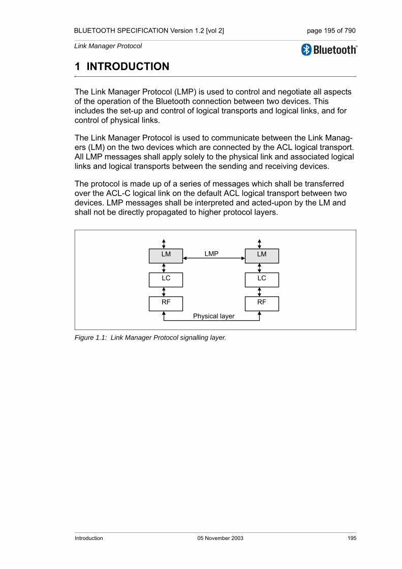
BLUETOOTH SPECIFICATION Version 1.2 [vol 2] page 195 of 790
Link Manager Protocol
1 INTRODUCTION
The Link Manager Protocol (LMP) is used to control and negotiate all aspects of the operation of the Bluetooth connection between two devices. This includes the set-up and control of logical transports and logical links, and for control of physical links.
The Link Manager Protocol is used to communicate between the Link Manag-ers (LM) on the two devices which are connected by the ACL logical transport. All LMP messages shall apply solely to the physical link and associated logical links and logical transports between the sending and receiving devices.
The protocol is made up of a series of messages which shall be transferred over the ACL-C logical link on the default ACL logical transport between two devices. LMP messages shall be interpreted and acted-upon by the LM and shall not be directly propagated to higher protocol layers.
Figure 1.1: Link Manager Protocol signalling layer.
LM
LC
RF
LM
LC
RF
LMP
Physical layer
Introduction 05 November 2003 195

BLUETOOTH SPECIFICATION Version 1.2 [vol 2] page 196 of 790
Link Manager Protocol
196 05 November 2003 Introduction

BLUETOOTH SPECIFICATION Version 1.2 [vol 2] page 197 of 790
Link Manager Protocol
2 GENERAL RULES
2.1 MESSAGE TRANSPORT
LMP messages shall be exchanged over the ACL-C logical link that is carried on the default ACL logical transport (Baseband Specification, Section 4.4, on page 86). The ACL-C logical link is distinguished from the ACL-U (which car-ries L2CAP and user data) by the Logical Link Identifier (LLID) field carried in the payload header of variable-length packets (Baseband Specification, Sec-tion 6.6.2, on page 113).
The ACL-C has a higher priority than other traffic - see Baseband Specification, Section 5.6, on page 96.
The error detection and correction capabilities of the baseband ACL logical transport are generally sufficient for the requirements of the LMP. Therefore LMP messages do not contain any additional error detection information beyond what can be realized by means of sanity checks performed on the con-tents of LMP messages. Any such checks and protections to overcome unde-tected errors in LMP messages is an implementation matter.
2.2 SYNCHRONIZATION
This section is informative and explains why many of the LMP message sequences are defined as they are.
LMP messages are carried on the ACL-C logical link, which does not guaran-tee a time to deliver or acknowledge packets. LMP procedures take account of this when synchronizing state changes in the two devices. For example, criteria are defined that specify when a logical transport address (LT_ADDR) may be re-used after it becomes available due to a device leaving the piconet or enter-ing the park state. Other LMP procedures, such as hold or role switch include the Bluetooth clock as a parameter in order to define a fixed synchronization point. The transitions into and out of sniff mode are protected with a transition mode.
The LC normally attempts to communicate with each slave no less often than every Tpoll slots (see Section 4.1.8 on page 220) based on the Tpoll for that slave.
General Rules 05 November 2003 197
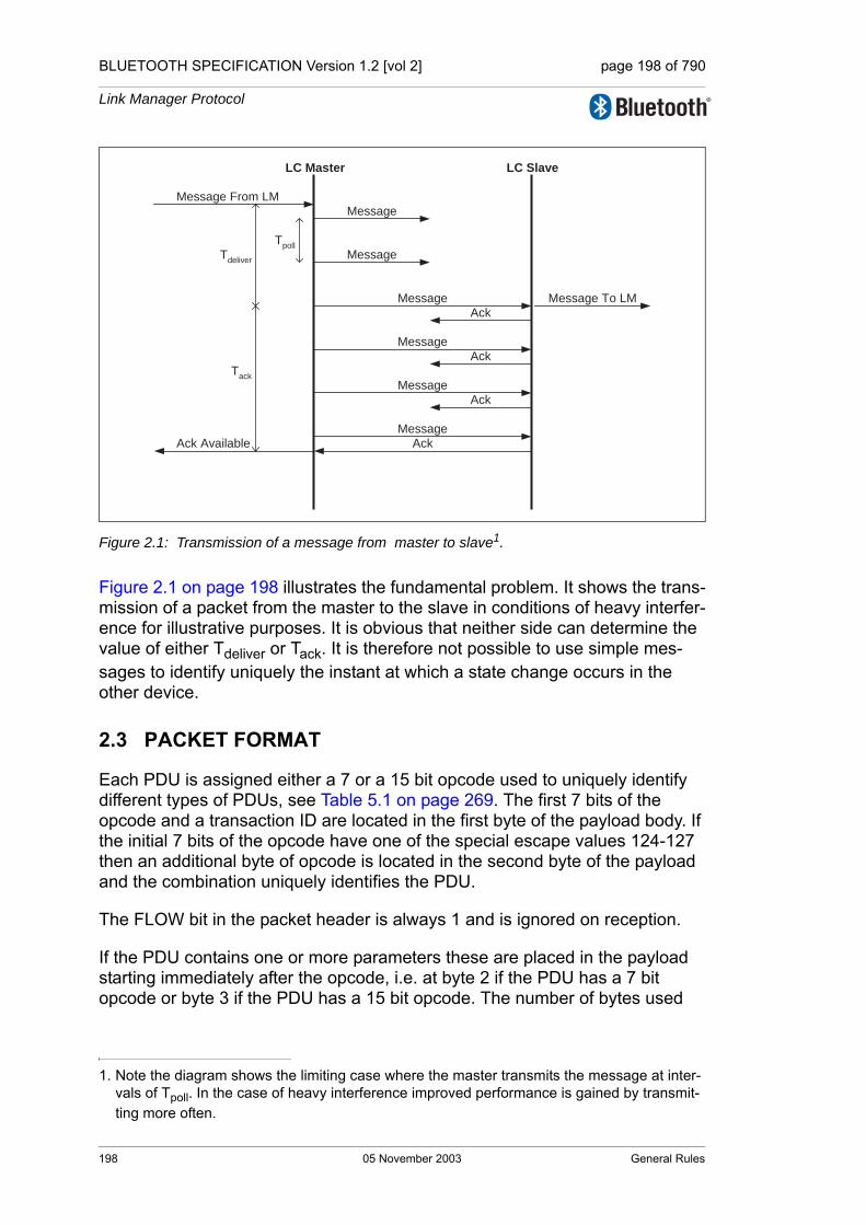
BLUETOOTH SPECIFICATION Version 1.2 [vol 2] page 198 of 790
Link Manager Protocol
Figure 2.1: Transmission of a message from master to slave1.
Figure 2.1 on page 198 illustrates the fundamental problem. It shows the trans-mission of a packet from the master to the slave in conditions of heavy interfer-ence for illustrative purposes. It is obvious that neither side can determine the value of either Tdeliver or Tack. It is therefore not possible to use simple mes-sages to identify uniquely the instant at which a state change occurs in the other device.
2.3 PACKET FORMAT
Each PDU is assigned either a 7 or a 15 bit opcode used to uniquely identify different types of PDUs, see Table 5.1 on page 269. The first 7 bits of the opcode and a transaction ID are located in the first byte of the payload body. If the initial 7 bits of the opcode have one of the special escape values 124-127 then an additional byte of opcode is located in the second byte of the payload and the combination uniquely identifies the PDU.
The FLOW bit in the packet header is always 1 and is ignored on reception.
If the PDU contains one or more parameters these are placed in the payload starting immediately after the opcode, i.e. at byte 2 if the PDU has a 7 bit opcode or byte 3 if the PDU has a 15 bit opcode. The number of bytes used
1. Note the diagram shows the limiting case where the master transmits the message at inter-vals of Tpoll. In the case of heavy interference improved performance is gained by transmit-ting more often.
LC Master LC Slave
Message From LMMessage
Message
Message Message To LM
Message
Message
Message
Ack
Ack
Ack
AckAck Available
TpollTdeliver
Tack
198 05 November 2003 General Rules

BLUETOOTH SPECIFICATION Version 1.2 [vol 2] page 199 of 790
Link Manager Protocol
depends on the length of the parameters. All parameters have a little-endian format, i.e. the least significant byte is transferred first.
LMP messages shall be transmitted using DM1 packets, however if an HV1 SCO link is in use and the length of the payload is less than 9 bytes then DV packets may be used.
Figure 2.2: Payload body when LMP PDUs are sent.
2.4 TRANSACTIONS
The LMP operates in terms of transactions. A transaction is a connected set of message exchanges which achieve a particular purpose. All PDUs which form part of the same transaction shall have the same value for the transaction ID which is stored as part of the first byte of the opCode (see Section 2.3 on page 198).
The transaction ID is in the least significant bit. It shall be 0 if the PDU forms part of a transaction that was initiated by the master and 1 if the transaction was initiated by the slave.
Each sequence described in Section 4 on page 209 shall be defined as a trans-action. For pairing, see Section 4.2.2 on page 226, and encryption, see Section 4.2.5 on page 232, all sequences belonging to each section shall be counted as one transaction and shall use the same transaction ID. For connection establishment, see Section 4.1.1 on page 209, LMP_host_connection_req and the response with LMP_accepted or LMP_not_accepted shall form one trans-action and have the transaction ID of 0. LMP_setup_complete is a stand-alone PDU, which forms a transaction by itself.
For error handling, see Section 2.5 on page 200, the PDU to be rejected and LMP_not_accepted or LMP_not_accepted_ext shall form a single transaction.
OpCodeT I D
Payload
LSB MSB
LMP PDU with 7 bit opCode
EscapeOpCode
ExtendedOpCode
T I D
Payload
LSB MSB
LMP PDU with 15 bit opCode
General Rules 05 November 2003 199
BLUETOOTH SPECIFICATION Version 1.2 [vol 2] page 200 of 790
Link Manager Protocol
2.4.1 LMP Response Timeout
The time between receiving a baseband packet carrying an LMP PDU and sending a baseband packet carrying a valid response PDU, according to the procedure rules in Section 4 on page 209, shall be less than the LMP Response Timeout. The value of this timeout is 30 seconds. Note that the LMP Response Timeout is applied not only to sequences described in Section 4 on page 209, but also to the series of the sequences defined as the transactions in Section 4 on page 209. It shall also be applied to the series of LMP transac-tions that take place during a period when traffic on the ACL-U logical link is disabled for the duration of the series of LMP transactions, for example during the enabling of encryption.
The LMP Response Timeout shall restart each time an LMP PDU which requires a reply is queued for transmission by the baseband.
2.5 ERROR HANDLINGIf the LM receives a PDU with unrecognized opcode, it shall respond with LMP_not_accepted or LMP_not_accepted_ext with the error code unknown LMP PDU. The opcode parameter that is echoed back is the unrecognized opcode.
If the LM receives a PDU with invalid parameters, it shall respond with LMP_not_accepted or LMP_not_accepted_ext with the error code invalid LMP parameters.
If the maximum response time, see Section 2.4 on page 199, is exceeded or if a link loss is detected (see Baseband Specification, Section 3.1, on page 83), the party that waits for the response shall conclude that the procedure has ter-minated unsuccessfully.
Erroneous LMP messages can be caused by errors on the channel or system-atic errors at the transmit side. To detect the latter case, the LM should monitor the number of erroneous messages and disconnect if it exceeds a threshold, which is implementation-dependent.
When the LM receives a PDU that is not allowed, and the PDU normally expects a PDU reply, for example LMP_host_connection_req or LMP_unit_key, the LM shall return PDU LMP_not_accepted or LMP_not_accepted_ext with the error code PDU not allowed. If the PDU normally doesn’t expect a reply, for example LMP_sres or LMP_temp_key, the PDU will be ignored.
The reception of an optional PDU which is not supported shall be handled in one of two ways: if the LM simply does not know the opcode (e.g. it was added at a later version of the specification) it shall respond with LMP_not_accepted or LMP_not_accepted_ext with the error code unknown LMP PDU. If the LM recognises the PDU as optional but unsupported then it shall reply with LMP_not_accepted or LMP_not_accepted_ext with the error code unsup-ported LMP feature if the PDU would normally generate a reply otherwise no reply is generated.
200 05 November 2003 General Rules
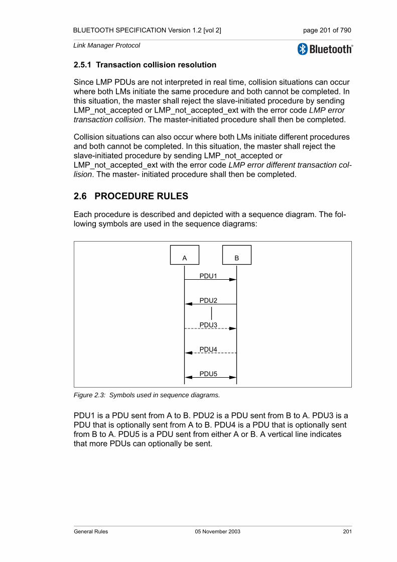
BLUETOOTH SPECIFICATION Version 1.2 [vol 2] page 201 of 790
Link Manager Protocol
2.5.1 Transaction collision resolution
Since LMP PDUs are not interpreted in real time, collision situations can occur where both LMs initiate the same procedure and both cannot be completed. In this situation, the master shall reject the slave-initiated procedure by sending LMP_not_accepted or LMP_not_accepted_ext with the error code LMP error transaction collision. The master-initiated procedure shall then be completed.
Collision situations can also occur where both LMs initiate different procedures and both cannot be completed. In this situation, the master shall reject the slave-initiated procedure by sending LMP_not_accepted or LMP_not_accepted_ext with the error code LMP error different transaction col-lision. The master- initiated procedure shall then be completed.
2.6 PROCEDURE RULES
Each procedure is described and depicted with a sequence diagram. The fol-lowing symbols are used in the sequence diagrams:
Figure 2.3: Symbols used in sequence diagrams.
PDU1 is a PDU sent from A to B. PDU2 is a PDU sent from B to A. PDU3 is a PDU that is optionally sent from A to B. PDU4 is a PDU that is optionally sent from B to A. PDU5 is a PDU sent from either A or B. A vertical line indicates that more PDUs can optionally be sent.
A B
PDU1
PDU2
PDU3
PDU4
PDU5
General Rules 05 November 2003 201

BLUETOOTH SPECIFICATION Version 1.2 [vol 2] page 202 of 790
Link Manager Protocol
2.7 GENERAL RESPONSE MESSAGES
The PDUs LMP_accepted, LMP_accepted_ext, LMP_not_accepted and LMP_not_accepted_ext are used as response messages to other PDUs in a number of different procedures. LMP_accepted or LMP_accepted_ext includes the opcode of the message which is accepted. LMP_not_accepted or LMP_not_accepted_ext includes the opcode of the message which is not accepted and the error code why it is not accepted.
LMP_accepted_ext and LMP_not_accepted_ext shall be used when the opcode is 15 bits in length. LMP_accepted and LMP_not_accepted shall be used when the opcode is 7 bits in length.
2.8 LMP MESSAGE CONSTRAINTS
This section is informative.
• No LMP message shall exceed the maximum payload length of a single DM1 packet i.e. 17 bytes in length (Baseband Specification, Section 6.5.4.1, on page 111).
• All LM messages are of fixed length apart from those sent using broadcast in park state.
• The LMP version number shall not be used to indicate the presence or absence of functionality.
M/O PDU Contents
M LMP_accepted op code
M LMP_not_accepted op codeerror code
O LMP_accepted_ext escape op codeextended op code
O LMP_not_accepted_ext escape op codeextended op codeerror code
Table 2.1: General response messages.
202 05 November 2003 General Rules

BLUETOOTH SPECIFICATION Version 1.2 [vol 2] page 203 of 790
Link Manager Protocol
3 DEVICE FEATURES
3.1 GENERAL DESCRIPTION
Each PDU is either Mandatory or Optional as defined by the M/O field in the tables of Section 4 on page 209. An M in this field shall indicate that support for the feature is mandatory. An O in this field shall indicate that support for the PDU is optional and it shall be followed by the number(s) of the feature(s) involved in brackets.
All features added after the 1.1 specification have associated LMP feature bits. Support of these features may be made “mandatory” by the qualification pro-cess but the LM still considers them to be optional since it must interoperate with older devices which do not support them.
The LM does not need to be able to transmit a PDU which is optional. Support of optional PDUs is indicated by a device's features mask. The features mask can be read (see Section 4.3.4 on page 239). An LM shall not send or be sent any PDU which is incompatible with the features signalled in its or its peer's features mask, as detailed in Section 3.2 .
3.2 FEATURE DEFINITIONS
Feature Definition
Extended featuresThis feature indicates whether the device is able to support the extended features mask using the LMP sequences defined in Sec-tion 4.3.4 on page 239.
Timing accuracy This feature indicates whether the LM supports requests for timing accuracy using the sequence defined in Section 4.3.1 on page 237.
Enhanced inquiry scan
This feature indicates whether the device is capable of supporting the enhanced inquiry scan mechanism as defined in Baseband Specification, Section 8.4.1, on page 144. The presence of this fea-ture has only local meaning and does not imply support for any addi-tional LMP PDUs or sequences.
Interlaced inquiry scan
This feature indicates whether the device is capable of supporting the interlaced inquiry scan mechanism as defined in Baseband Spec-ification, Section 8.4.1, on page 144. The presence of this feature has only local meaning and does not imply support for any additional LMP PDUs or sequences.
Interlaced page scan
This feature indicates whether the device is capable of supporting the interlaced page scan mechanism as defined in Baseband Specifi-cation, Section 8.3.1, on page 134. The presence of this feature has only local meaning and does not imply support for any additional LMP PDUs or sequences.
Table 3.1: Feature definitions.
Device Features 05 November 2003 203
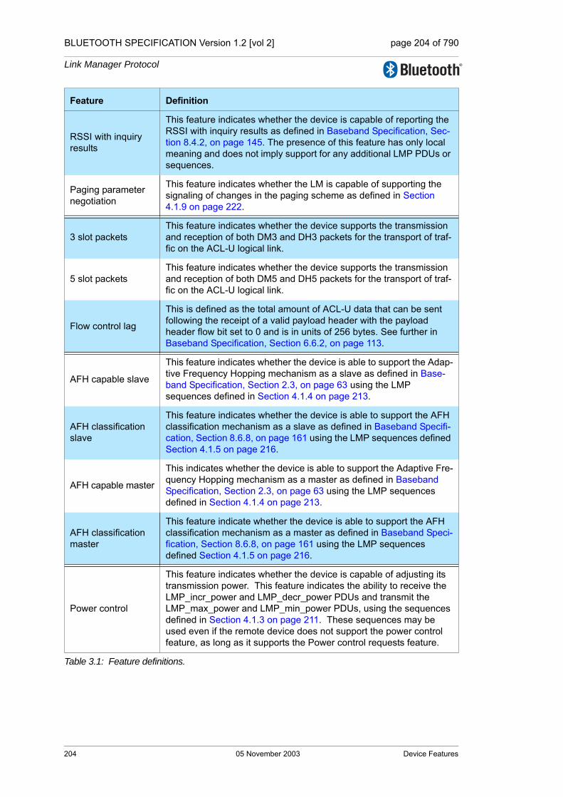
BLUETOOTH SPECIFICATION Version 1.2 [vol 2] page 204 of 790
Link Manager Protocol
RSSI with inquiry results
This feature indicates whether the device is capable of reporting the RSSI with inquiry results as defined in Baseband Specification, Sec-tion 8.4.2, on page 145. The presence of this feature has only local meaning and does not imply support for any additional LMP PDUs or sequences.
Paging parameter negotiation
This feature indicates whether the LM is capable of supporting the signaling of changes in the paging scheme as defined in Section 4.1.9 on page 222.
3 slot packetsThis feature indicates whether the device supports the transmission and reception of both DM3 and DH3 packets for the transport of traf-fic on the ACL-U logical link.
5 slot packetsThis feature indicates whether the device supports the transmission and reception of both DM5 and DH5 packets for the transport of traf-fic on the ACL-U logical link.
Flow control lag
This is defined as the total amount of ACL-U data that can be sent following the receipt of a valid payload header with the payload header flow bit set to 0 and is in units of 256 bytes. See further in Baseband Specification, Section 6.6.2, on page 113.
AFH capable slave
This feature indicates whether the device is able to support the Adap-tive Frequency Hopping mechanism as a slave as defined in Base-band Specification, Section 2.3, on page 63 using the LMP sequences defined in Section 4.1.4 on page 213.
AFH classification slave
This feature indicates whether the device is able to support the AFH classification mechanism as a slave as defined in Baseband Specifi-cation, Section 8.6.8, on page 161 using the LMP sequences defined Section 4.1.5 on page 216.
AFH capable master
This indicates whether the device is able to support the Adaptive Fre-quency Hopping mechanism as a master as defined in Baseband Specification, Section 2.3, on page 63 using the LMP sequences defined in Section 4.1.4 on page 213.
AFH classification master
This feature indicate whether the device is able to support the AFH classification mechanism as a master as defined in Baseband Speci-fication, Section 8.6.8, on page 161 using the LMP sequences defined Section 4.1.5 on page 216.
Power control
This feature indicates whether the device is capable of adjusting its transmission power. This feature indicates the ability to receive the LMP_incr_power and LMP_decr_power PDUs and transmit the LMP_max_power and LMP_min_power PDUs, using the sequences defined in Section 4.1.3 on page 211. These sequences may be used even if the remote device does not support the power control feature, as long as it supports the Power control requests feature.
Feature Definition
Table 3.1: Feature definitions.
204 05 November 2003 Device Features

BLUETOOTH SPECIFICATION Version 1.2 [vol 2] page 205 of 790
Link Manager Protocol
Power control requests
This feature indicates whether the device is capable of determining if the transmit power level of the other device should be adjusted and will send the LMP_incr_power and LMP_decr_power PDUs to request the adjustments. It indicates the ability to receive the LMP_max_power and LMP_min_power PDUs, using the sequences in Section 4.1.3 on page 211. These sequences may be used even if the remote device does not support the RSSI feature, as long as it supports the power control feature.
Channel Quality Driven Data Rate
This feature indicates whether the LM is capable of recommending a packet type (or types) depending on the channel quality using the LMP sequences defined in section Section 4.1.7 on page 219.
Broadcast encryp-tion
This feature indicates whether the device is capable of supporting broadcast encryption as defined in [Part H] Section 4.2 on page 764 and also the sequences defined in Section 4.2.6 on page 236 and Section 4.2.4 on page 230.Note: Devices compliant to versions of this specification 1.1 and ear-lier may support broadcast encryption even though this feature bit is not set.
EncryptionThis feature indicates whether the device supports the encryption of packet contents using the sequence defined in Section 4.2.5 on page 232.
Slot offset This feature indicates whether the LM supports the transfer of the slot offset using the sequence defined in Section 4.4.1 on page 242.
Role switchThis feature indicates whether the device supports the change of master and slave roles as defined by baseband Section 8.6.5 on page 155 using the sequence defined in Section 4.4.2 on page 243.
Hold modeThis feature indicates whether the device is able to support Hold mode as defined in baseband Section 8.8 on page 165 using the LMP sequences defined in Section 4.5.1 on page 245.
Sniff modeThis feature indicates whether the device is able to support Sniff mode as defined in baseband Section 8.7 on page 163 using the LMP sequences defined in Section 4.5.3 on page 253.
Park stateThis feature indicates whether the device is able to support Park state as defined in baseband Section 8.9 on page 165 using the LMP sequences defined in Section 4.5.2 on page 247.
SCO link
This feature shall indicate whether the device is able to support the SCO logical transport as defined in Baseband Specification, Section 4.3, on page 86, the HV1 packet defined in Baseband Specification, Section 6.5.2.1, on page 109 and receiving the DV packet defined in Baseband Specification, Section 6.5.2.4, on page 109 using the LMP sequence in Section 4.6.1 on page 256.
HV2 packetsThis feature indicates whether the device is capable of supporting the HV2 packet type as defined in baseband Section 6.5.2.2 on page 109 on the SCO logical transport.
Feature Definition
Table 3.1: Feature definitions.
Device Features 05 November 2003 205

BLUETOOTH SPECIFICATION Version 1.2 [vol 2] page 206 of 790
Link Manager Protocol
HV3 packetsThis feature indicates whether the device is capable of supporting the HV3 packet type as defined in baseband Section 6.5.2.3 on page 109 on the SCO logical transport.
µ-law log synchro-nous data
This feature indicates whether the device is capable of supporting µ-Law Log format data as defined in Baseband Specification, Section 9.1, on page 173 on the SCO and eSCO logical transports.
A-law log synchro-nous data
This feature indicates whether the device is capable of supporting A-Law Log format data as defined in Baseband Specification, Section 9.1, on page 173 on the SCO and eSCO logical transports.
CVSD synchro-nous data
This feature indicates whether the device is capable of supporting CVSD format data as defined in Baseband Specification, Section 9.2, on page 173 on the SCO and eSCO logical transports.
Transparent synchronous data
This feature indicates whether the device is capable of supporting transparent synchronous data as defined in Baseband Specification, Section 6.4.3, on page 104 on the SCO and eSCO logical transports.
Extended SCO link
This feature indicates whether the device is able to support the eSCO logical transport as defined Baseband Specification, Section 5.5, on page 96 and the EV3 packet defined in Baseband Specifica-tion, Section 6.5.3.1, on page 110 using the LMP sequences defined in Section 4.6.2 on page 259.
EV4 packetsThis feature indicates whether the device is capable of supporting the EV4 packet type defined in Baseband Specification, Section 6.5.3.2, on page 110 on the eSCO logical transport.
EV5 packetsThis feature indicates whether the device is capable of supporting the EV5 packet type defined in Baseband Specification, Section 6.5.3.3, on page 110 on the eSCO logical transport.
Feature Definition
Table 3.1: Feature definitions.
206 05 November 2003 Device Features
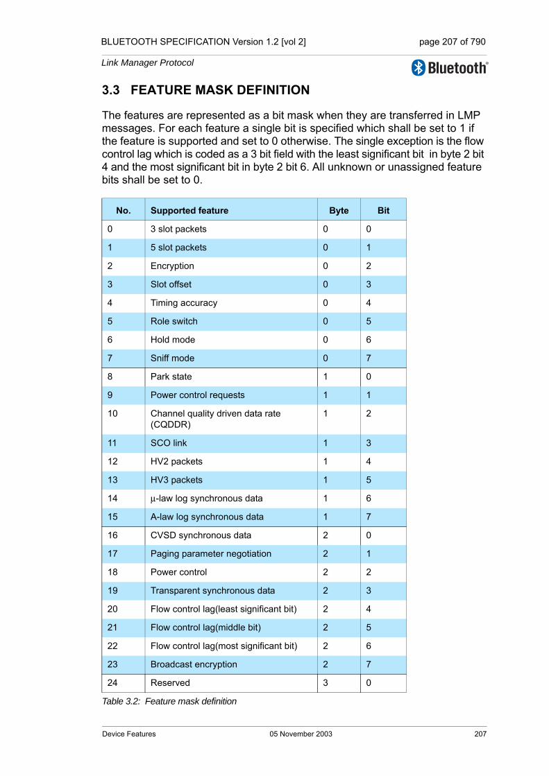
BLUETOOTH SPECIFICATION Version 1.2 [vol 2] page 207 of 790
Link Manager Protocol
3.3 FEATURE MASK DEFINITION
The features are represented as a bit mask when they are transferred in LMP messages. For each feature a single bit is specified which shall be set to 1 if the feature is supported and set to 0 otherwise. The single exception is the flow control lag which is coded as a 3 bit field with the least significant bit in byte 2 bit 4 and the most significant bit in byte 2 bit 6. All unknown or unassigned feature bits shall be set to 0.
No. Supported feature Byte Bit
0 3 slot packets 0 0
1 5 slot packets 0 1
2 Encryption 0 2
3 Slot offset 0 3
4 Timing accuracy 0 4
5 Role switch 0 5
6 Hold mode 0 6
7 Sniff mode 0 7
8 Park state 1 0
9 Power control requests 1 1
10 Channel quality driven data rate (CQDDR)
1 2
11 SCO link 1 3
12 HV2 packets 1 4
13 HV3 packets 1 5
14 µ-law log synchronous data 1 6
15 A-law log synchronous data 1 7
16 CVSD synchronous data 2 0
17 Paging parameter negotiation 2 1
18 Power control 2 2
19 Transparent synchronous data 2 3
20 Flow control lag(least significant bit) 2 4
21 Flow control lag(middle bit) 2 5
22 Flow control lag(most significant bit) 2 6
23 Broadcast encryption 2 7
24 Reserved 3 0
Table 3.2: Feature mask definition
Device Features 05 November 2003 207
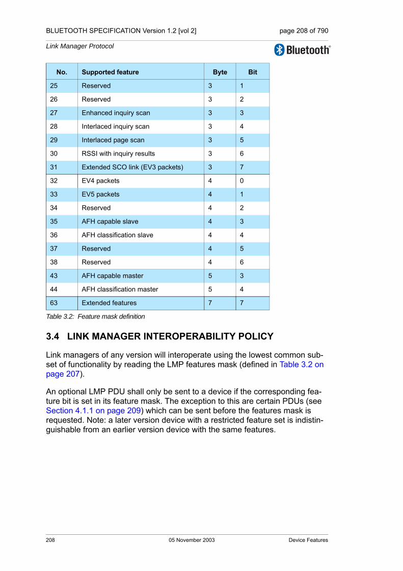
BLUETOOTH SPECIFICATION Version 1.2 [vol 2] page 208 of 790
Link Manager Protocol
3.4 LINK MANAGER INTEROPERABILITY POLICY
Link managers of any version will interoperate using the lowest common sub-set of functionality by reading the LMP features mask (defined in Table 3.2 on page 207).
An optional LMP PDU shall only be sent to a device if the corresponding fea-ture bit is set in its feature mask. The exception to this are certain PDUs (see Section 4.1.1 on page 209) which can be sent before the features mask is requested. Note: a later version device with a restricted feature set is indistin-guishable from an earlier version device with the same features.
25 Reserved 3 1
26 Reserved 3 2
27 Enhanced inquiry scan 3 3
28 Interlaced inquiry scan 3 4
29 Interlaced page scan 3 5
30 RSSI with inquiry results 3 6
31 Extended SCO link (EV3 packets) 3 7
32 EV4 packets 4 0
33 EV5 packets 4 1
34 Reserved 4 2
35 AFH capable slave 4 3
36 AFH classification slave 4 4
37 Reserved 4 5
38 Reserved 4 6
43 AFH capable master 5 3
44 AFH classification master 5 4
63 Extended features 7 7
No. Supported feature Byte Bit
Table 3.2: Feature mask definition
208 05 November 2003 Device Features
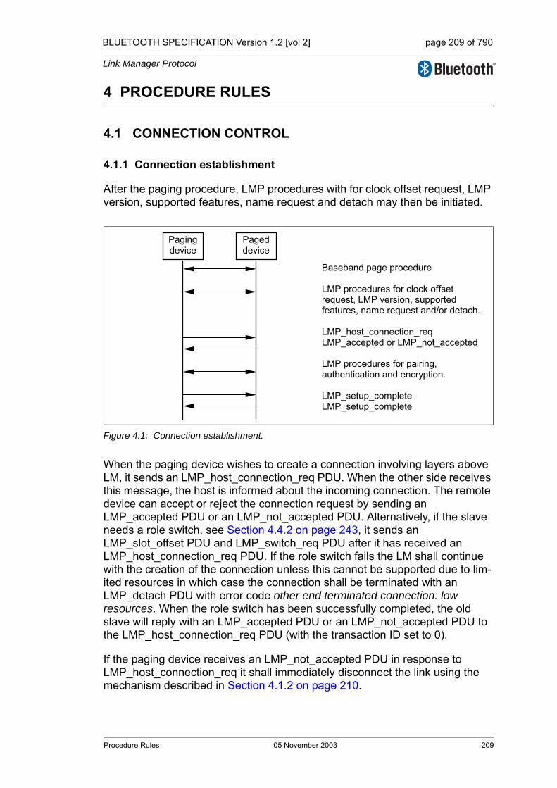
BLUETOOTH SPECIFICATION Version 1.2 [vol 2] page 209 of 790
Link Manager Protocol
4 PROCEDURE RULES
4.1 CONNECTION CONTROL
4.1.1 Connection establishment
After the paging procedure, LMP procedures with for clock offset request, LMP version, supported features, name request and detach may then be initiated.
Figure 4.1: Connection establishment.
When the paging device wishes to create a connection involving layers above LM, it sends an LMP_host_connection_req PDU. When the other side receives this message, the host is informed about the incoming connection. The remote device can accept or reject the connection request by sending an LMP_accepted PDU or an LMP_not_accepted PDU. Alternatively, if the slave needs a role switch, see Section 4.4.2 on page 243, it sends an LMP_slot_offset PDU and LMP_switch_req PDU after it has received an LMP_host_connection_req PDU. If the role switch fails the LM shall continue with the creation of the connection unless this cannot be supported due to lim-ited resources in which case the connection shall be terminated with an LMP_detach PDU with error code other end terminated connection: low resources. When the role switch has been successfully completed, the old slave will reply with an LMP_accepted PDU or an LMP_not_accepted PDU to the LMP_host_connection_req PDU (with the transaction ID set to 0).
If the paging device receives an LMP_not_accepted PDU in response to LMP_host_connection_req it shall immediately disconnect the link using the mechanism described in Section 4.1.2 on page 210.
Paging device
Paged device
Baseband page procedure LMP procedures for clock offset request, LMP version, supported features, name request and/or detach. LMP_host_connection_req LMP_accepted or LMP_not_accepted LMP procedures for pairing, authentication and encryption. LMP_setup_complete LMP_setup_complete
Procedure Rules 05 November 2003 209
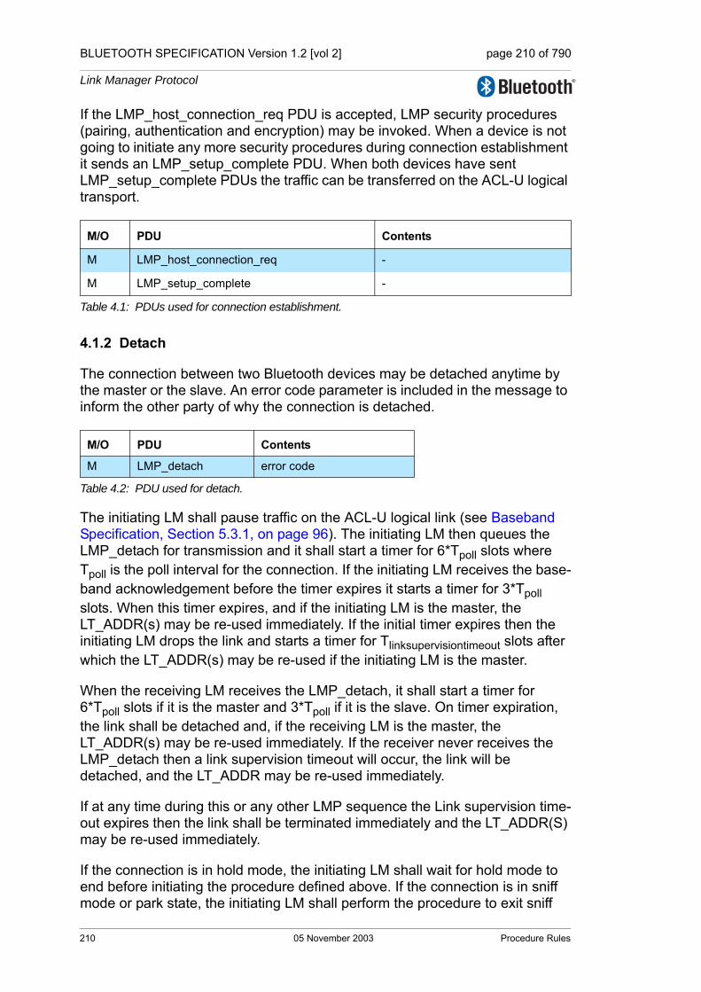
BLUETOOTH SPECIFICATION Version 1.2 [vol 2] page 210 of 790
Link Manager Protocol
If the LMP_host_connection_req PDU is accepted, LMP security procedures (pairing, authentication and encryption) may be invoked. When a device is not going to initiate any more security procedures during connection establishment it sends an LMP_setup_complete PDU. When both devices have sent LMP_setup_complete PDUs the traffic can be transferred on the ACL-U logical transport.
4.1.2 Detach
The connection between two Bluetooth devices may be detached anytime by the master or the slave. An error code parameter is included in the message to inform the other party of why the connection is detached.
The initiating LM shall pause traffic on the ACL-U logical link (see Baseband Specification, Section 5.3.1, on page 96). The initiating LM then queues the LMP_detach for transmission and it shall start a timer for 6*Tpoll slots where Tpoll is the poll interval for the connection. If the initiating LM receives the base-band acknowledgement before the timer expires it starts a timer for 3*Tpoll slots. When this timer expires, and if the initiating LM is the master, the LT_ADDR(s) may be re-used immediately. If the initial timer expires then the initiating LM drops the link and starts a timer for Tlinksupervisiontimeout slots after which the LT_ADDR(s) may be re-used if the initiating LM is the master.
When the receiving LM receives the LMP_detach, it shall start a timer for 6*Tpoll slots if it is the master and 3*Tpoll if it is the slave. On timer expiration, the link shall be detached and, if the receiving LM is the master, the LT_ADDR(s) may be re-used immediately. If the receiver never receives the LMP_detach then a link supervision timeout will occur, the link will be detached, and the LT_ADDR may be re-used immediately.
If at any time during this or any other LMP sequence the Link supervision time-out expires then the link shall be terminated immediately and the LT_ADDR(S) may be re-used immediately.
If the connection is in hold mode, the initiating LM shall wait for hold mode to end before initiating the procedure defined above. If the connection is in sniff mode or park state, the initiating LM shall perform the procedure to exit sniff
M/O PDU Contents
M LMP_host_connection_req -
M LMP_setup_complete -
Table 4.1: PDUs used for connection establishment.
M/O PDU Contents
M LMP_detach error code
Table 4.2: PDU used for detach.
210 05 November 2003 Procedure Rules
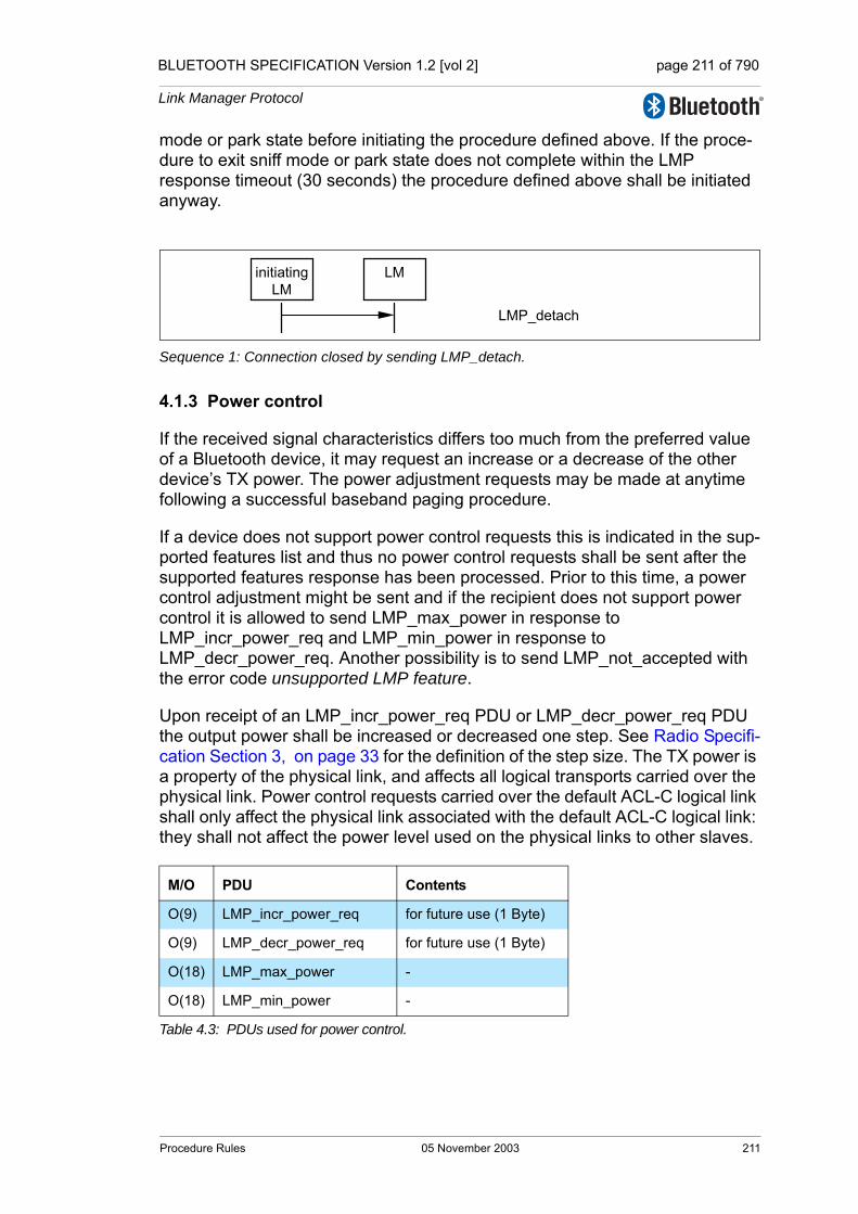
BLUETOOTH SPECIFICATION Version 1.2 [vol 2] page 211 of 790
Link Manager Protocol
mode or park state before initiating the procedure defined above. If the proce-dure to exit sniff mode or park state does not complete within the LMP response timeout (30 seconds) the procedure defined above shall be initiated anyway.
Sequence 1: Connection closed by sending LMP_detach.
4.1.3 Power control
If the received signal characteristics differs too much from the preferred value of a Bluetooth device, it may request an increase or a decrease of the other device’s TX power. The power adjustment requests may be made at anytime following a successful baseband paging procedure.
If a device does not support power control requests this is indicated in the sup-ported features list and thus no power control requests shall be sent after the supported features response has been processed. Prior to this time, a power control adjustment might be sent and if the recipient does not support power control it is allowed to send LMP_max_power in response to LMP_incr_power_req and LMP_min_power in response to LMP_decr_power_req. Another possibility is to send LMP_not_accepted with the error code unsupported LMP feature.
Upon receipt of an LMP_incr_power_req PDU or LMP_decr_power_req PDU the output power shall be increased or decreased one step. See Radio Specifi-cation Section 3, on page 33 for the definition of the step size. The TX power is a property of the physical link, and affects all logical transports carried over the physical link. Power control requests carried over the default ACL-C logical link shall only affect the physical link associated with the default ACL-C logical link: they shall not affect the power level used on the physical links to other slaves.
M/O PDU Contents
O(9) LMP_incr_power_req for future use (1 Byte)
O(9) LMP_decr_power_req for future use (1 Byte)
O(18) LMP_max_power -
O(18) LMP_min_power -
Table 4.3: PDUs used for power control.
initiatingLM
LM
LMP_detach
Procedure Rules 05 November 2003 211

BLUETOOTH SPECIFICATION Version 1.2 [vol 2] page 212 of 790
Link Manager Protocol
Sequence 2: A device requests a change of the other device’s TX power.
If the receiver of LMP_incr_power_req is at maximum power LMP_max_power shall be returned. The device shall only request an increase again after having requested a decrease at least once. If the receiver of LMP_decr_power_req is at minimum power then LMP_min_power shall be returned and the device shall only request a decrease after having requested an increase at least once.
Sequence 3: The TX power cannot be increased.
Sequence 4: The TX power cannot be decreased.
One byte is reserved in LMP_incr/decr_power_req for future use. The parame-ter value shall be 0x00 and ignored upon receipt.
InitiatingLM
LM
LMP_incr_power_reqorLMP_decr_power_req
InitiatingLM
LM
LMP_incr_power_reqLMP_max_power
InitiatingLM
LM
LMP_decr_power_reqLMP_min_power
212 05 November 2003 Procedure Rules
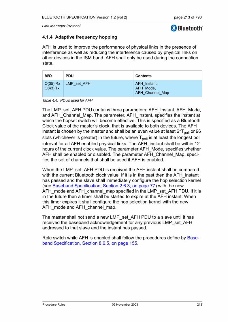
BLUETOOTH SPECIFICATION Version 1.2 [vol 2] page 213 of 790
Link Manager Protocol
4.1.4 Adaptive frequency hopping
AFH is used to improve the performance of physical links in the presence of interference as well as reducing the interference caused by physical links on other devices in the ISM band. AFH shall only be used during the connection state.
The LMP_set_AFH PDU contains three parameters: AFH_Instant, AFH_Mode, and AFH_Channel_Map. The parameter, AFH_Instant, specifies the instant at which the hopset switch will become effective. This is specified as a Bluetooth Clock value of the master’s clock, that is available to both devices. The AFH instant is chosen by the master and shall be an even value at least 6*Tpoll or 96 slots (whichever is greater) in the future, where Tpoll is at least the longest poll interval for all AFH enabled physical links. The AFH_instant shall be within 12 hours of the current clock value. The parameter AFH_Mode, specifies whether AFH shall be enabled or disabled. The parameter AFH_Channel_Map, speci-fies the set of channels that shall be used if AFH is enabled.
When the LMP_set_AFH PDU is received the AFH instant shall be compared with the current Bluetooth clock value. If it is in the past then the AFH_instant has passed and the slave shall immediately configure the hop selection kernel (see Baseband Specification, Section 2.6.3, on page 77) with the new AFH_mode and AFH_channel_map specified in the LMP_set_AFH PDU. If it is in the future then a timer shall be started to expire at the AFH instant. When this timer expires it shall configure the hop selection kernel with the new AFH_mode and AFH_channel_map.
The master shall not send a new LMP_set_AFH PDU to a slave until it has received the baseband acknowledgement for any previous LMP_set_AFH addressed to that slave and the instant has passed.
Role switch while AFH is enabled shall follow the procedures define by Base-band Specification, Section 8.6.5, on page 155.
M/O PDU Contents
O(35) RxO(43) Tx
LMP_set_AFH AFH_Instant, AFH_Mode, AFH_Channel_Map
Table 4.4: PDUs used for AFH
Procedure Rules 05 November 2003 213
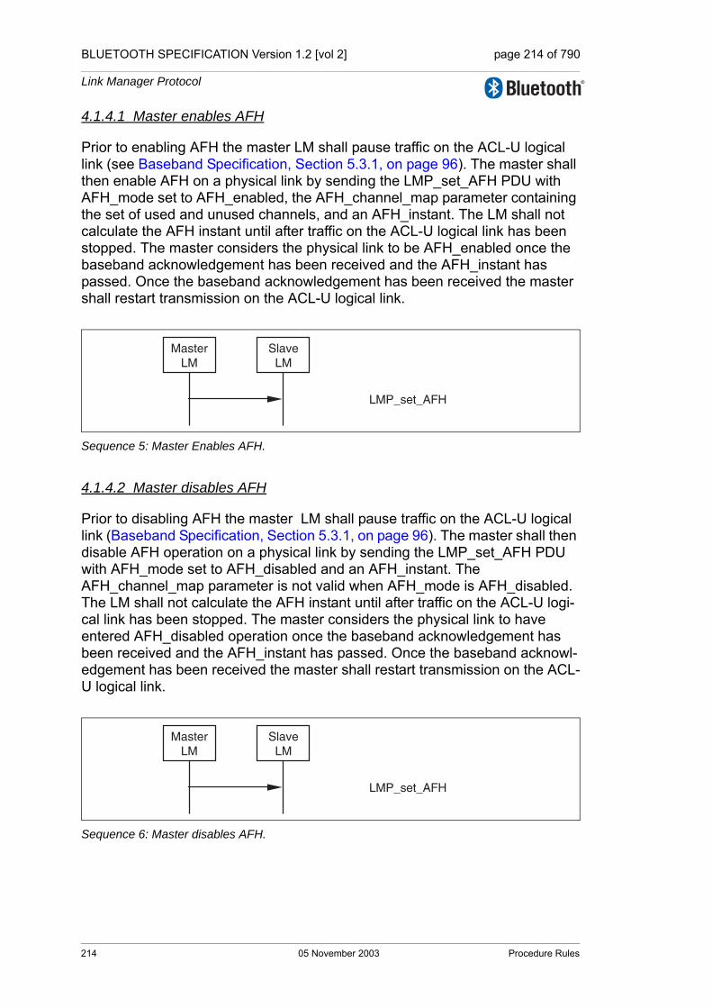
BLUETOOTH SPECIFICATION Version 1.2 [vol 2] page 214 of 790
Link Manager Protocol
4.1.4.1 Master enables AFH
Prior to enabling AFH the master LM shall pause traffic on the ACL-U logical link (see Baseband Specification, Section 5.3.1, on page 96). The master shall then enable AFH on a physical link by sending the LMP_set_AFH PDU with AFH_mode set to AFH_enabled, the AFH_channel_map parameter containing the set of used and unused channels, and an AFH_instant. The LM shall not calculate the AFH instant until after traffic on the ACL-U logical link has been stopped. The master considers the physical link to be AFH_enabled once the baseband acknowledgement has been received and the AFH_instant has passed. Once the baseband acknowledgement has been received the master shall restart transmission on the ACL-U logical link.
Sequence 5: Master Enables AFH.
4.1.4.2 Master disables AFH
Prior to disabling AFH the master LM shall pause traffic on the ACL-U logical link (Baseband Specification, Section 5.3.1, on page 96). The master shall then disable AFH operation on a physical link by sending the LMP_set_AFH PDU with AFH_mode set to AFH_disabled and an AFH_instant. The AFH_channel_map parameter is not valid when AFH_mode is AFH_disabled. The LM shall not calculate the AFH instant until after traffic on the ACL-U logi-cal link has been stopped. The master considers the physical link to have entered AFH_disabled operation once the baseband acknowledgement has been received and the AFH_instant has passed. Once the baseband acknowl-edgement has been received the master shall restart transmission on the ACL-U logical link.
Sequence 6: Master disables AFH.
LMP_set_AFH
MasterLM
SlaveLM
LMP_set_AFH
MasterLM
SlaveLM
214 05 November 2003 Procedure Rules
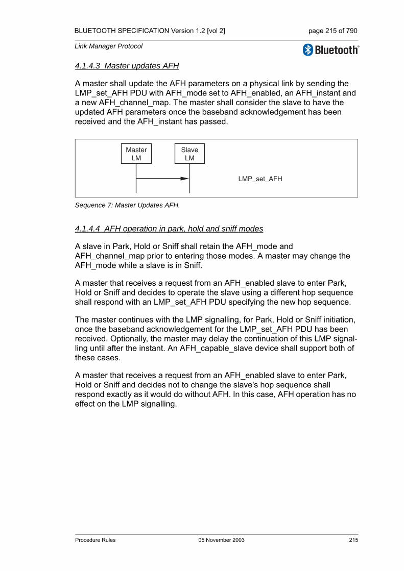
BLUETOOTH SPECIFICATION Version 1.2 [vol 2] page 215 of 790
Link Manager Protocol
4.1.4.3 Master updates AFH
A master shall update the AFH parameters on a physical link by sending the LMP_set_AFH PDU with AFH_mode set to AFH_enabled, an AFH_instant and a new AFH_channel_map. The master shall consider the slave to have the updated AFH parameters once the baseband acknowledgement has been received and the AFH_instant has passed.
Sequence 7: Master Updates AFH.
4.1.4.4 AFH operation in park, hold and sniff modes
A slave in Park, Hold or Sniff shall retain the AFH_mode and AFH_channel_map prior to entering those modes. A master may change the AFH_mode while a slave is in Sniff.
A master that receives a request from an AFH_enabled slave to enter Park, Hold or Sniff and decides to operate the slave using a different hop sequence shall respond with an LMP_set_AFH PDU specifying the new hop sequence.
The master continues with the LMP signalling, for Park, Hold or Sniff initiation, once the baseband acknowledgement for the LMP_set_AFH PDU has been received. Optionally, the master may delay the continuation of this LMP signal-ling until after the instant. An AFH_capable_slave device shall support both of these cases.
A master that receives a request from an AFH_enabled slave to enter Park, Hold or Sniff and decides not to change the slave's hop sequence shall respond exactly as it would do without AFH. In this case, AFH operation has no effect on the LMP signalling.
LMP_set_AFH
MasterLM
SlaveLM
Procedure Rules 05 November 2003 215

BLUETOOTH SPECIFICATION Version 1.2 [vol 2] page 216 of 790
Link Manager Protocol
4.1.5 Channel classification
A master may request channel classification information from a slave that is AFH_enabled.
A slave that supports the AFH_classification_slave feature shall perform chan-nel classification and reporting according to its AFH_reporting_mode. The master shall control the AFH_reporting_mode using the LMP_channel_classification_req PDU. The slave shall report its channel clas-sification using the LMP_channel_classification PDU.
The slave shall report pairs of channels as good, bad or unknown. See Table 5.2 on page 277 for the detailed format of the AFH_Channel_Classification parameter. When one channel in the nth channel pair is good and the other channel is unknown the nth channel pair shall be reported as good. When one channel in the nth channel pair is bad and the other is unknown the nth channel pair shall be reported as bad. It is implementation dependent what to report when one channel in a channel pair is good and the other is bad.
The LMP_channel_classification_req PDU contains three parameters: AFH_Reporting_Mode, AFH_Min_Interval, and AFH_Max_Interval. In the AFH_reporting_disabled state, the slave shall not generate any channel classi-fication reports. The parameter AFH_min_interval, defines the minimum amount of time from the last LMP_channel_classification command that was sent before the next LMP_channel_classification PDU may be sent. The parameter AFH_max_interval, defines the maximum amount of time between the change in the radio environment being detected by a slave and its genera-tion of an LMP_channel_classification PDU. The AFH_max_interval shall be equal to or larger than AFH_min_interval.
The AFH_reporting_mode parameter shall determine if the slave is in the AFH_reporting_enabled or AFH_reporting_disabled state. The default state, prior to receipt of any LMP_channel_classification_req PDUs, shall be AFH_reporting_disabled.
AFH_reporting_mode is implicitly set to the AFH_reporting_disabled state when any of the following occur:
• Establishment of a connection at the baseband level• Master-slave role switch
M/O PDU Contents
O(36) RxO(44) Tx
LMP_channel_classification_req AFH_Reporting_Mode,AFH_Min_Interval,AFH_Max_Interval
O(36) TxO(44) Rx
LMP_channel_classification AFH_Channel_Classification
Table 4.5: PDUs used for Channel Classification Reporting.
216 05 November 2003 Procedure Rules

BLUETOOTH SPECIFICATION Version 1.2 [vol 2] page 217 of 790
Link Manager Protocol
• Entry to park state operation• Entry to hold mode operation
AFH_reporting_mode is implicitly restored to its former value when any of the following occur:
• Exit from park state operation• Exit from hold mode• Failure of Master-slave role switch
4.1.5.1 Channel classification reporting enabling and disabling
A master enables slave channel classification reporting by sending the LMP_channel_classification_req PDU with the AFH_reporting_mode parame-ter set to AFH_reporting_enabled.
When a slave has had classification reporting enabled by the master it shall send the LMP_channel_classification PDU according to the information in the latest LMP_channel_classification_req PDU. The LMP_channel_classification PDU shall not be sent if there has been no change in the slave’s channel clas-sification.
A master disables slave channel classification reporting by sending the LMP_channel_classification_req PDU with the AFH_reporting_mode parame-ter set to AFH_reporting_disabled.
Sequence 8: Channel classification reporting.
LMP_channel_classification_req (enable)
MasterLM
SlaveLM
LMP_channel_classification
LMP_channel_classification
LMP_channel_classification_req (disable)
. . .
. . .
. . .
Procedure Rules 05 November 2003 217
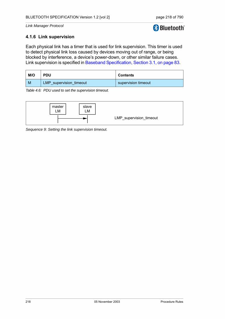
BLUETOOTH SPECIFICATION Version 1.2 [vol 2] page 218 of 790
Link Manager Protocol
4.1.6 Link supervision
Each physical link has a timer that is used for link supervision. This timer is used to detect physical link loss caused by devices moving out of range, or being blocked by interference, a device’s power-down, or other similar failure cases. Link supervision is specified in Baseband Specification, Section 3.1, on page 83.
Sequence 9: Setting the link supervision timeout.
M/O PDU Contents
M LMP_supervision_timeout supervision timeout
Table 4.6: PDU used to set the supervision timeout.
masterLM
slaveLM
LMP_supervision_timeout
218 05 November 2003 Procedure Rules

BLUETOOTH SPECIFICATION Version 1.2 [vol 2] page 219 of 790
Link Manager Protocol
4.1.7 Channel quality driven data rate change (CQDDR)
The data throughput for a given packet type depends on the quality of the RF channel. Quality measurements in the receiver of one device can be used to dynamically control the packet type transmitted from the remote device for opti-mization of the data throughput. Device A sends the LMP_auto_rate PDU once to notify device B to enable this feature. Once enabled, device B may change the packet type(s) that A transmits by sending the LMP_preferred_rate PDU. This PDU has a parameter which determines the preferred coding (with or with-out 2/3FEC) and optionally the preferred size in slots of the packets. Device A is not required to change to the packet type specified by this parameter. Device A shall not send a packet that is larger than max slots (see Section 4.1.10 on page 223) even if the preferred size is greater than this value.
These PDUs may be sent at any time after connection setup is completed.
Sequence 10: A notifies B to enable CQDDR
Sequence 11: B sends A a preferred packet type
M/O PDU Contents
O(10) LMP_auto_rate -
O(10) LMP_preferred_rate data rate
Table 4.7: PDUs used for quality driven change of the data rate.
A LM B LM
LMP_auto_rate
A LM B LM
LMP_preferred_rate
Procedure Rules 05 November 2003 219
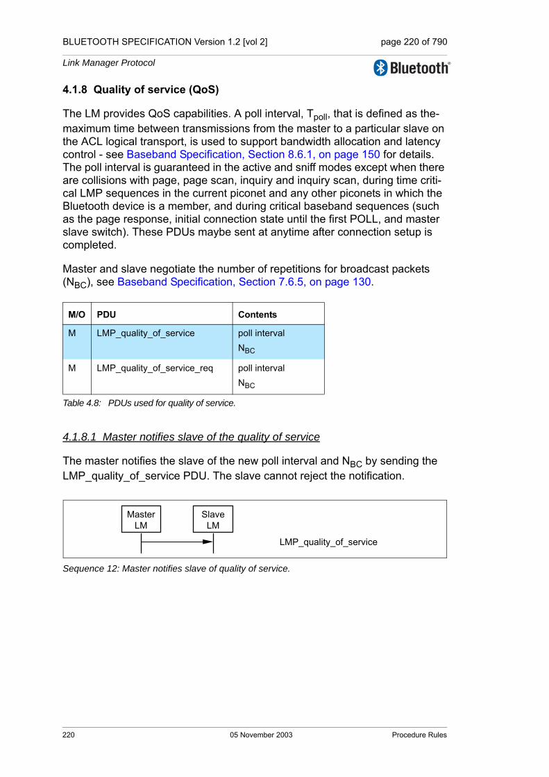
BLUETOOTH SPECIFICATION Version 1.2 [vol 2] page 220 of 790
Link Manager Protocol
4.1.8 Quality of service (QoS)
The LM provides QoS capabilities. A poll interval, Tpoll, that is defined as the-maximum time between transmissions from the master to a particular slave on the ACL logical transport, is used to support bandwidth allocation and latency control - see Baseband Specification, Section 8.6.1, on page 150 for details. The poll interval is guaranteed in the active and sniff modes except when there are collisions with page, page scan, inquiry and inquiry scan, during time criti-cal LMP sequences in the current piconet and any other piconets in which the Bluetooth device is a member, and during critical baseband sequences (such as the page response, initial connection state until the first POLL, and master slave switch). These PDUs maybe sent at anytime after connection setup is completed.
Master and slave negotiate the number of repetitions for broadcast packets (NBC), see Baseband Specification, Section 7.6.5, on page 130.
4.1.8.1 Master notifies slave of the quality of service
The master notifies the slave of the new poll interval and NBC by sending the LMP_quality_of_service PDU. The slave cannot reject the notification.
Sequence 12: Master notifies slave of quality of service.
M/O PDU Contents
M LMP_quality_of_service poll intervalNBC
M LMP_quality_of_service_req poll intervalNBC
Table 4.8: PDUs used for quality of service.
MasterLM
SlaveLM
LMP_quality_of_service
220 05 November 2003 Procedure Rules

BLUETOOTH SPECIFICATION Version 1.2 [vol 2] page 221 of 790
Link Manager Protocol
4.1.8.2 Device requests new quality of service
Either the master or the slave may request a new poll interval and NBC by sending an LMP_quality_of_service_req PDU to the slave. The parameter NBC is meaningful only when it is sent by a master to a slave. For transmission of LMP_quality_of_service_req PDUs from a slave, this parameter shall be ignored by the master. The request can be accepted or rejected. This allows the master and slave to dynamically negotiate the quality of service as needed.
The selected poll interval by the slave shall be less than or equal to the speci-fied Access Latency for the outgoing traffic of the ACL link (see L2CAP “Quality of Service (QoS) Option” on page 60[vol. 3]).
Sequence 13: Device accepts new quality of service
Sequence 14: Device rejects new quality of service.
InitiatingLM LM
LMP_quality_of_service_reqLMP_accepted
InitiatingLM LM
LMP_quality_of_service_reqLMP_not_accepted
Procedure Rules 05 November 2003 221
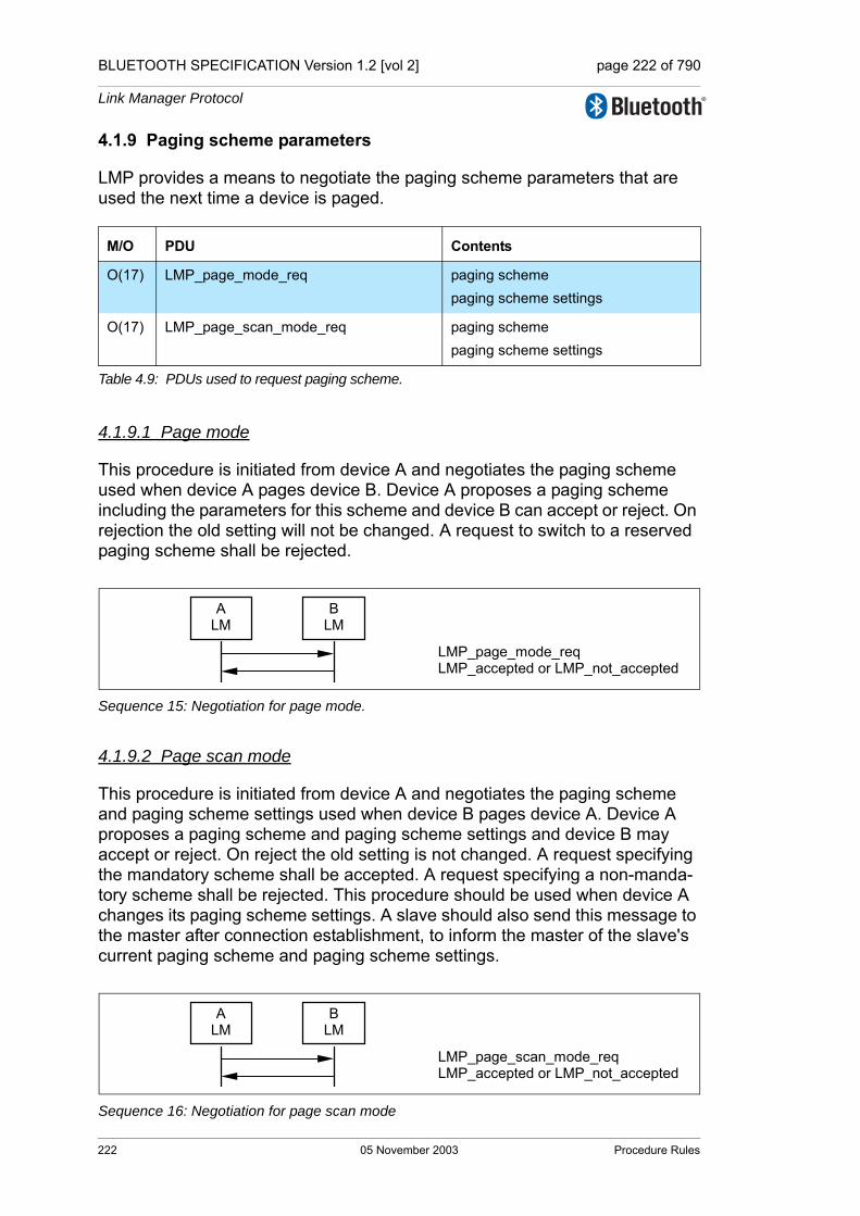
BLUETOOTH SPECIFICATION Version 1.2 [vol 2] page 222 of 790
Link Manager Protocol
4.1.9 Paging scheme parameters
LMP provides a means to negotiate the paging scheme parameters that are used the next time a device is paged.
4.1.9.1 Page mode
This procedure is initiated from device A and negotiates the paging scheme used when device A pages device B. Device A proposes a paging scheme including the parameters for this scheme and device B can accept or reject. On rejection the old setting will not be changed. A request to switch to a reserved paging scheme shall be rejected.
Sequence 15: Negotiation for page mode.
4.1.9.2 Page scan mode
This procedure is initiated from device A and negotiates the paging scheme and paging scheme settings used when device B pages device A. Device A proposes a paging scheme and paging scheme settings and device B may accept or reject. On reject the old setting is not changed. A request specifying the mandatory scheme shall be accepted. A request specifying a non-manda-tory scheme shall be rejected. This procedure should be used when device A changes its paging scheme settings. A slave should also send this message to the master after connection establishment, to inform the master of the slave's current paging scheme and paging scheme settings.
Sequence 16: Negotiation for page scan mode
M/O PDU Contents
O(17) LMP_page_mode_req paging schemepaging scheme settings
O(17) LMP_page_scan_mode_req paging schemepaging scheme settings
Table 4.9: PDUs used to request paging scheme.
ALM
BLM
LMP_page_mode_reqLMP_accepted or LMP_not_accepted
ALM
BLM
LMP_page_scan_mode_reqLMP_accepted or LMP_not_accepted
222 05 November 2003 Procedure Rules
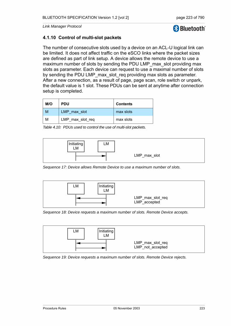
BLUETOOTH SPECIFICATION Version 1.2 [vol 2] page 223 of 790
Link Manager Protocol
4.1.10 Control of multi-slot packets
The number of consecutive slots used by a device on an ACL-U logical link can be limited. It does not affect traffic on the eSCO links where the packet sizes are defined as part of link setup. A device allows the remote device to use a maximum number of slots by sending the PDU LMP_max_slot providing max slots as parameter. Each device can request to use a maximal number of slots by sending the PDU LMP_max_slot_req providing max slots as parameter. After a new connection, as a result of page, page scan, role switch or unpark, the default value is 1 slot. These PDUs can be sent at anytime after connection setup is completed.
Sequence 17: Device allows Remote Device to use a maximum number of slots.
Sequence 18: Device requests a maximum number of slots. Remote Device accepts.
Sequence 19: Device requests a maximum number of slots. Remote Device rejects.
M/O PDU Contents
M LMP_max_slot max slots
M LMP_max_slot_req max slots
Table 4.10: PDUs used to control the use of multi-slot packets.
Initiating LM
LM
LMP_max_slot
LM InitiatingLM
LMP_max_slot_req LMP_accepted
LM InitiatingLM
LMP_max_slot_req LMP_not_accepted
Procedure Rules 05 November 2003 223

BLUETOOTH SPECIFICATION Version 1.2 [vol 2] page 224 of 790
Link Manager Protocol
4.2 SECURITY
4.2.1 Authentication
The authentication procedure is based on a challenge-response scheme as described in [Part H] Section 5 on page 773. The verifier sends an LMP_au_rand PDU that contains a random number (the challenge) to the claimant. The claimant calculates a response, that is a function of this chal-lenge, the claimant’s BD_ADDR and a secret key. The response is sent back to the verifier, that checks if the response was correct or not. The response shall be calculated as described in [Part H] Section 6.1 on page 777. A successful calculation of the authentication response requires that two devices share a secret key. This key is created as described in Section 4.2.2 on page 226. Both the master and the slave can be verifiers.
4.2.1.1 Claimant has link key
If the claimant has a link key associated with the verifier, it shall calculate the response and sends it to the verifier with LMP_sres. The verifier checks the response. If the response is not correct, the verifier can end the connection by sending an LMP_detach PDU with the error code authentication failure, see Section 4.1.2 on page 210.
Sequence 20: Authentication. Claimant has link key.
Upon reception of an LMP_au_rand, an LM shall reply with LMP_sres before initi-ating its own authentication. Note: there can be concurrent requests caused by the master and slave simulta-neously initiating an authentication. The procedures in Section 2.5.1 on page 201 assures that devices will not have different Authenticated Cyphering Offset (ACO, see [Part H] Section 6.1 on page 777) when they calculate the encryption key.
M/O PDU Contents
M LMP_au_rand random number
M LMP_sres authentication response
Table 4.11: PDUs used for authentication.
verifierLM
claimantLM
LMP_au_randLMP_sres
224 05 November 2003 Procedure Rules

BLUETOOTH SPECIFICATION Version 1.2 [vol 2] page 225 of 790
Link Manager Protocol
4.2.1.2 Claimant has no link key
If the claimant does not have a link key associated with the verifier it shall send an LMP_not_accepted PDU with the error code key missing after receiving an LMP_au_rand PDU.
Sequence 21: Authentication fails. Claimant has no link key.
4.2.1.3 Repeated attempts
The scheme described in [Part H] Section 5.1 on page 775 shall be applied when an authentication fails. This will prevent an intruder from trying a large number of keys in a relatively short time.
verifierLM
claimantLM
LMP_au_randLMP_not_accepted
Procedure Rules 05 November 2003 225
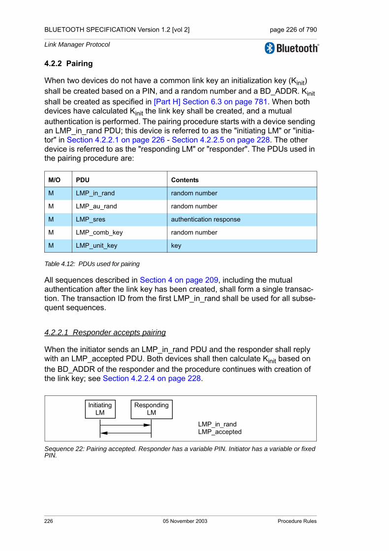
BLUETOOTH SPECIFICATION Version 1.2 [vol 2] page 226 of 790
Link Manager Protocol
4.2.2 Pairing
When two devices do not have a common link key an initialization key (Kinit) shall be created based on a PIN, and a random number and a BD_ADDR. Kinit shall be created as specified in [Part H] Section 6.3 on page 781. When both devices have calculated Kinit the link key shall be created, and a mutual authentication is performed. The pairing procedure starts with a device sending an LMP_in_rand PDU; this device is referred to as the "initiating LM" or "initia-tor" in Section 4.2.2.1 on page 226 - Section 4.2.2.5 on page 228. The other device is referred to as the "responding LM" or "responder". The PDUs used in the pairing procedure are:
Table 4.12: PDUs used for pairing
All sequences described in Section 4 on page 209, including the mutual authentication after the link key has been created, shall form a single transac-tion. The transaction ID from the first LMP_in_rand shall be used for all subse-quent sequences.
4.2.2.1 Responder accepts pairing
When the initiator sends an LMP_in_rand PDU and the responder shall reply with an LMP_accepted PDU. Both devices shall then calculate Kinit based on the BD_ADDR of the responder and the procedure continues with creation of the link key; see Section 4.2.2.4 on page 228.
Sequence 22: Pairing accepted. Responder has a variable PIN. Initiator has a variable or fixed PIN.
M/O PDU Contents
M LMP_in_rand random number
M LMP_au_rand random number
M LMP_sres authentication response
M LMP_comb_key random number
M LMP_unit_key key
Initiating LM
Responding LM
LMP_in_rand LMP_accepted
226 05 November 2003 Procedure Rules
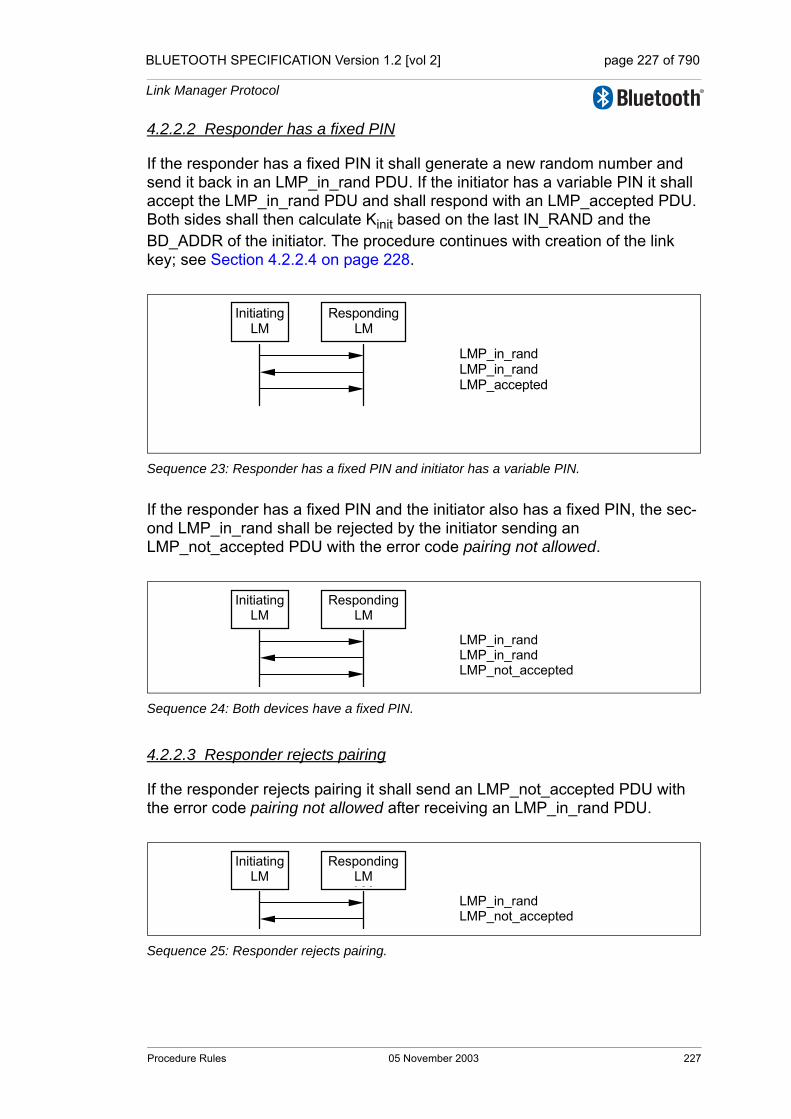
BLUETOOTH SPECIFICATION Version 1.2 [vol 2] page 227 of 790
Link Manager Protocol
4.2.2.2 Responder has a fixed PIN
If the responder has a fixed PIN it shall generate a new random number and send it back in an LMP_in_rand PDU. If the initiator has a variable PIN it shall accept the LMP_in_rand PDU and shall respond with an LMP_accepted PDU. Both sides shall then calculate Kinit based on the last IN_RAND and the BD_ADDR of the initiator. The procedure continues with creation of the link key; see Section 4.2.2.4 on page 228.
Sequence 23: Responder has a fixed PIN and initiator has a variable PIN.
If the responder has a fixed PIN and the initiator also has a fixed PIN, the sec-ond LMP_in_rand shall be rejected by the initiator sending an LMP_not_accepted PDU with the error code pairing not allowed.
Sequence 24: Both devices have a fixed PIN.
4.2.2.3 Responder rejects pairing
If the responder rejects pairing it shall send an LMP_not_accepted PDU with the error code pairing not allowed after receiving an LMP_in_rand PDU.
Sequence 25: Responder rejects pairing.
Initiating LM
Responding LM
LMP_in_rand LMP_in_rand LMP_accepted
Initiating LM
Responding LM
LMP_in_rand LMP_in_rand LMP_not_accepted
Initiating LM
RespondingLM LM
LMP_in_rand LMP_not_accepted
Procedure Rules 05 November 2003 227
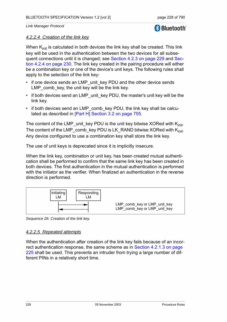
BLUETOOTH SPECIFICATION Version 1.2 [vol 2] page 228 of 790
Link Manager Protocol
4.2.2.4 Creation of the link key
When Kinit is calculated in both devices the link key shall be created. This link key will be used in the authentication between the two devices for all subse-quent connections until it is changed; see Section 4.2.3 on page 229 and Sec-tion 4.2.4 on page 230. The link key created in the pairing procedure will either be a combination key or one of the device's unit keys. The following rules shall apply to the selection of the link key:
• if one device sends an LMP_unit_key PDU and the other device sends LMP_comb_key, the unit key will be the link key.
• if both devices send an LMP_unit_key PDU, the master's unit key will be the link key.
• if both devices send an LMP_comb_key PDU, the link key shall be calcu-lated as described in [Part H] Section 3.2 on page 755.
The content of the LMP_unit_key PDU is the unit key bitwise XORed with Kinit. The content of the LMP_comb_key PDU is LK_RAND bitwise XORed with Kinit. Any device configured to use a combination key shall store the link key.
The use of unit keys is deprecated since it is implicitly insecure.
When the link key, combination or unit key, has been created mutual authenti-cation shall be performed to confirm that the same link key has been created in both devices. The first authentication in the mutual authentication is performed with the initiator as the verifier. When finalized an authentication in the reverse direction is performed.
Sequence 26: Creation of the link key.
4.2.2.5 Repeated attempts
When the authentication after creation of the link key fails because of an incor-rect authentication response, the same scheme as in Section 4.2.1.3 on page 225 shall be used. This prevents an intruder from trying a large number of dif-ferent PINs in a relatively short time.
Initiating LM
RespondingLM
LMP_comb_key or LMP_unit_key LMP_comb_key or LMP_unit_key
228 05 November 2003 Procedure Rules
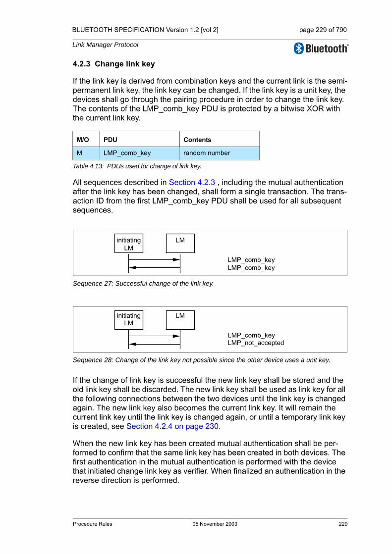
BLUETOOTH SPECIFICATION Version 1.2 [vol 2] page 229 of 790
Link Manager Protocol
4.2.3 Change link key
If the link key is derived from combination keys and the current link is the semi-permanent link key, the link key can be changed. If the link key is a unit key, the devices shall go through the pairing procedure in order to change the link key. The contents of the LMP_comb_key PDU is protected by a bitwise XOR with the current link key.
Sequence 27: Successful change of the link key.
Sequence 28: Change of the link key not possible since the other device uses a unit key.
If the change of link key is successful the new link key shall be stored and the old link key shall be discarded. The new link key shall be used as link key for all the following connections between the two devices until the link key is changed again. The new link key also becomes the current link key. It will remain the current link key until the link key is changed again, or until a temporary link key is created, see Section 4.2.4 on page 230.
When the new link key has been created mutual authentication shall be per-formed to confirm that the same link key has been created in both devices. The first authentication in the mutual authentication is performed with the device that initiated change link key as verifier. When finalized an authentication in the reverse direction is performed.
M/O PDU Contents
M LMP_comb_key random number
Table 4.13: PDUs used for change of link key.
All sequences described in Section 4.2.3 , including the mutual authentication after the link key has been changed, shall form a single transaction. The trans-action ID from the first LMP_comb_key PDU shall be used for all subsequent sequences.
initiatingLM
LM
LMP_comb_keyLMP_comb_key
initiatingLM
LM
LMP_comb_keyLMP_not_accepted
Procedure Rules 05 November 2003 229
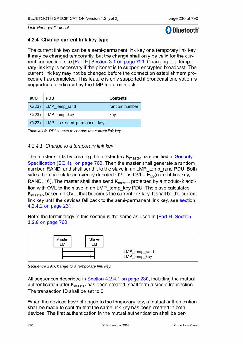
BLUETOOTH SPECIFICATION Version 1.2 [vol 2] page 230 of 790
Link Manager Protocol
4.2.4 Change current link key type
The current link key can be a semi-permanent link key or a temporary link key. It may be changed temporarily, but the change shall only be valid for the cur-rent connection, see [Part H] Section 3.1 on page 753. Changing to a tempo-rary link key is necessary if the piconet is to support encrypted broadcast. The current link key may not be changed before the connection establishment pro-cedure has completed. This feature is only supported if broadcast encryption is supported as indicated by the LMP features mask.
4.2.4.1 Change to a temporary link key
The master starts by creating the master key Kmaster as specified in Security Specification (EQ 4), on page 760. Then the master shall generate a random number, RAND, and shall send it to the slave in an LMP_temp_rand PDU. Both sides then calculate an overlay denoted OVL as OVL= E22(current link key, RAND, 16). The master shall then send Kmaster protected by a modulo-2 addi-tion with OVL to the slave in an LMP_temp_key PDU. The slave calculates Kmaster, based on OVL, that becomes the current link key. It shall be the current link key until the devices fall back to the semi-permanent link key, see section 4.2.4.2 on page 231.
Note: the terminology in this section is the same as used in [Part H] Section 3.2.8 on page 760.
Sequence 29: Change to a temporary link key.
All sequences described in Section 4.2.4.1 on page 230, including the mutual authentication after Kmaster has been created, shall form a single transaction. The transaction ID shall be set to 0.
When the devices have changed to the temporary key, a mutual authentication shall be made to confirm that the same link key has been created in both devices. The first authentication in the mutual authentication shall be per-
M/O PDU Contents
O(23) LMP_temp_rand random number
O(23) LMP_temp_key key
O(23) LMP_use_semi_permanent_key -
Table 4.14: PDUs used to change the current link key.
MasterLM
SlaveLM
LMP_temp_randLMP_temp_key
230 05 November 2003 Procedure Rules

BLUETOOTH SPECIFICATION Version 1.2 [vol 2] page 231 of 790
Link Manager Protocol
formed with the master as verifier. When finalized an authentication in the reverse direction is performed.
Should the mutual authentication fail at either side, the LM of the verifier should start the detach procedure. This will allow the procedure to succeed even though one of the devices may be erroneous.
4.2.4.2 Make the semi-permanent link key the current link key
After the current link key has been changed to Kmaster, this change can be undone and the semi-permanent link key becomes the current link key again. If encryption is used on the link, the procedure to go back to the semi-permanent link key shall be immediately followed by the master stopping encryption using the procedure described in Section 4.2.5.4 on page 235. Encryption may be restarted by the master according to the procedures in section 4.2.5.1 on page 232 subsection 3. This is to assure that encryption with encryption parameters known by other devices in the piconet is not used when the semi-permanent link key is the current link key.
Sequence 30: Link key changed to the semi-permanent link key.
MasterLM
SlaveLM
LMP_use_semi_permanent_keyLMP_accepted
Procedure Rules 05 November 2003 231
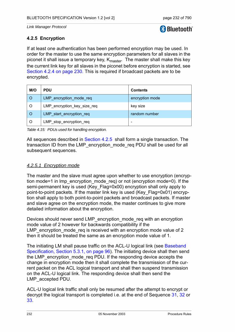
BLUETOOTH SPECIFICATION Version 1.2 [vol 2] page 232 of 790
Link Manager Protocol
4.2.5 Encryption
If at least one authentication has been performed encryption may be used. In order for the master to use the same encryption parameters for all slaves in the piconet it shall issue a temporary key, Kmaster. The master shall make this key the current link key for all slaves in the piconet before encryption is started, see Section 4.2.4 on page 230. This is required if broadcast packets are to be encrypted.
All sequences described in Section 4.2.5 shall form a single transaction. The transaction ID from the LMP_encryption_mode_req PDU shall be used for all subsequent sequences.
4.2.5.1 Encryption mode
The master and the slave must agree upon whether to use encryption (encryp-tion mode=1 in lmp_encryption_mode_req) or not (encryption mode=0). If the semi-permanent key is used (Key_Flag=0x00) encryption shall only apply to point-to-point packets. If the master link key is used (Key_Flag=0x01) encryp-tion shall apply to both point-to-point packets and broadcast packets. If master and slave agree on the encryption mode, the master continues to give more detailed information about the encryption.
Devices should never send LMP_encryption_mode_req with an encryption mode value of 2 however for backwards compatibility if the LMP_encryption_mode_req is received with an encryption mode value of 2 then it should be treated the same as an encryption mode value of 1.
The initiating LM shall pause traffic on the ACL-U logical link (see Baseband Specification, Section 5.3.1, on page 96). The initiating device shall then send the LMP_encryption_mode_req PDU. If the responding device accepts the change in encryption mode then it shall complete the transmission of the cur-rent packet on the ACL logical transport and shall then suspend transmission on the ACL-U logical link. The responding device shall then send the LMP_accepted PDU.
ACL-U logical link traffic shall only be resumed after the attempt to encrypt or decrypt the logical transport is completed i.e. at the end of Sequence 31, 32 or 33.
M/O PDU Contents
O LMP_encryption_mode_req encryption mode
O LMP_encryption_key_size_req key size
O LMP_start_encryption_req random number
O LMP_stop_encryption_req -
Table 4.15: PDUs used for handling encryption.
232 05 November 2003 Procedure Rules
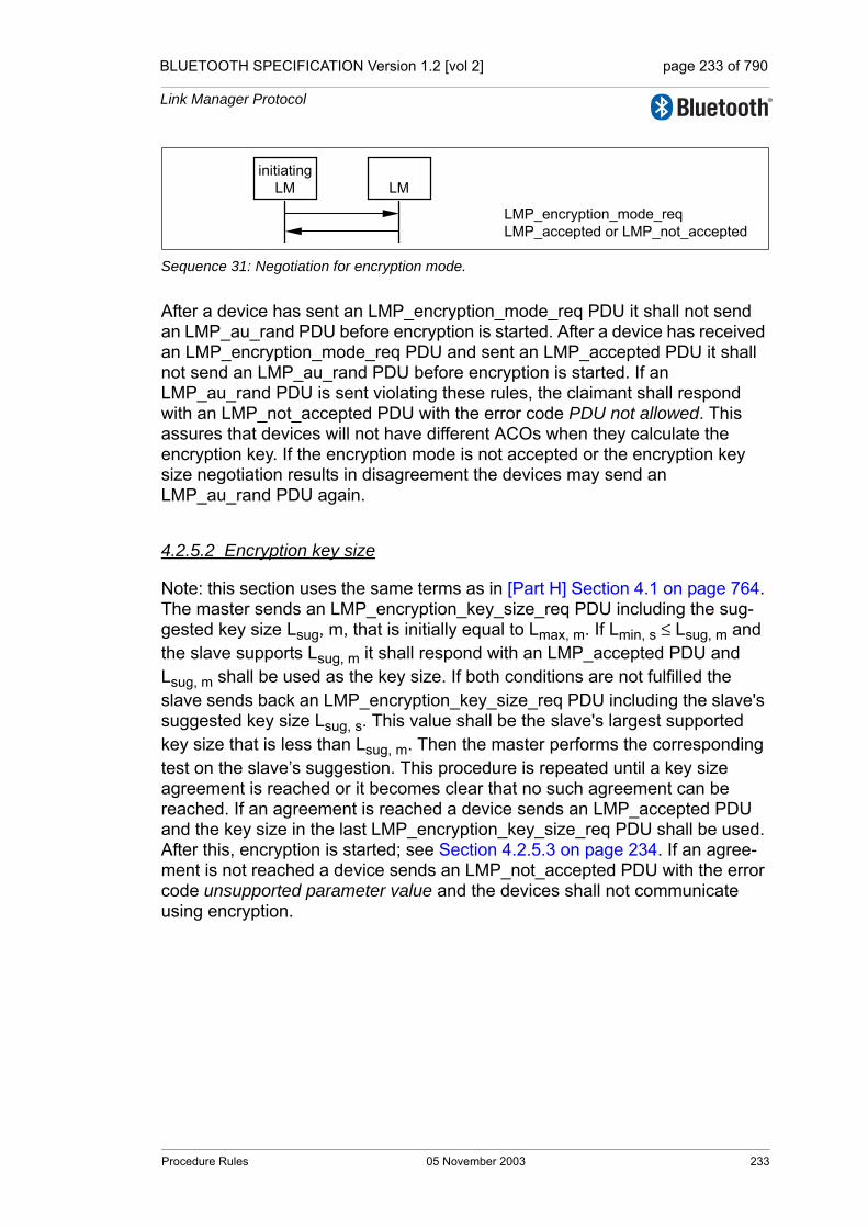
BLUETOOTH SPECIFICATION Version 1.2 [vol 2] page 233 of 790
Link Manager Protocol
Sequence 31: Negotiation for encryption mode.
After a device has sent an LMP_encryption_mode_req PDU it shall not send an LMP_au_rand PDU before encryption is started. After a device has received an LMP_encryption_mode_req PDU and sent an LMP_accepted PDU it shall not send an LMP_au_rand PDU before encryption is started. If an LMP_au_rand PDU is sent violating these rules, the claimant shall respond with an LMP_not_accepted PDU with the error code PDU not allowed. This assures that devices will not have different ACOs when they calculate the encryption key. If the encryption mode is not accepted or the encryption key size negotiation results in disagreement the devices may send an LMP_au_rand PDU again.
4.2.5.2 Encryption key size
Note: this section uses the same terms as in [Part H] Section 4.1 on page 764. The master sends an LMP_encryption_key_size_req PDU including the sug-gested key size Lsug, m, that is initially equal to Lmax, m. If Lmin, s ≤ Lsug, m and the slave supports Lsug, m it shall respond with an LMP_accepted PDU and Lsug, m shall be used as the key size. If both conditions are not fulfilled the slave sends back an LMP_encryption_key_size_req PDU including the slave's suggested key size Lsug, s. This value shall be the slave's largest supported key size that is less than Lsug, m. Then the master performs the corresponding test on the slave’s suggestion. This procedure is repeated until a key size agreement is reached or it becomes clear that no such agreement can be reached. If an agreement is reached a device sends an LMP_accepted PDU and the key size in the last LMP_encryption_key_size_req PDU shall be used. After this, encryption is started; see Section 4.2.5.3 on page 234. If an agree-ment is not reached a device sends an LMP_not_accepted PDU with the error code unsupported parameter value and the devices shall not communicate using encryption.
initiatingLM LM
LMP_encryption_mode_reqLMP_accepted or LMP_not_accepted
Procedure Rules 05 November 2003 233

BLUETOOTH SPECIFICATION Version 1.2 [vol 2] page 234 of 790
Link Manager Protocol
Sequence 32: Encryption key size negotiation successful.
Sequence 33: Encryption key size negotiation failed.
4.2.5.3 Start encryption
To start encryption, the master issues the random number EN_RAND and cal-culates the encryption key. See [Part H] Section 3.2.5 on page 758. The ran-dom number shall be the same for all slaves in the piconet when broadcast encryption is used. The master then sends an LMP_start_encryption_req PDU, that includes EN_RAND. The slave shall calculate the encryption key when this message is received and shall acknowledge with an LMP_accepted PDU.
Sequence 34: Start of encryption.
Starting encryption shall be performed in three steps:
1. Master is configured to transmit unencrypted packets and to receive encrypted packets.
2. Slave is configured to transmit and receive encrypted packets.
3. Master is configured to transmit and receive encrypted packets.
masterLM
slaveLM
LMP_encryption_key_size_reqLMP_encryption_key_size_reqLMP_encryption_key_size_req
LMP_accepted
masterLM
slaveLM
LMP_encryption_key_size_reqLMP_encryption_key_size_reqLMP_encryption_key_size_req
LMP_not_accepted
MasterLM
SlaveLM
LMP_start_encryption_reqLMP_accepted
234 05 November 2003 Procedure Rules
BLUETOOTH SPECIFICATION Version 1.2 [vol 2] page 235 of 790
Link Manager Protocol
Between step 1 and step 2, master-to-slave transmission is possible. This is when an LMP_start_encryption_req PDU is transmitted. Step 2 is triggered when the slave receives this message. Between step 2 and step 3, slave-to-master transmission is possible. This is when an LMP_accepted PDU is transmitted. Step 3 is triggered when the master receives this message.
4.2.5.4 Stop encryption
To stop encryption a device shall send an LMP_encryption_mode_req PDU with the parameter encryption mode equal to 0 (no encryption). The other device responds with an LMP_accepted PDU or an LMP_not_accepted PDU (the procedure is described in Sequence 31 in section 4.2.5.1 on page 232). If accepted, encryption shall be stopped by the master sending an LMP_stop_encryption_req PDU and the slave shall respond with an LMP_accepted PDU according to Sequence 35.
Sequence 35: Stop of encryption.
Stopping encryption shall be performed in three steps, similar to the procedure for starting encryption.
1. Master is configured to transmit encrypted packets and to receive unen-crypted packets.
2. Slave is configured to transmit and receive unencrypted packets.
3. Master is configured to transmit and receive unencrypted packets.
Between step 1 and step 2 master to slave transmission is possible. This is when an LMP_stop_encryption_req PDU is transmitted. Step 2 is triggered when the slave receives this message. Between step 2 and step 3 slave to master transmission is possible. This is when an LMP_accepted PDU is trans-mitted. Step 3 is triggered when the master receives this message.
4.2.5.5 Change encryption mode, key or random number
If the encryption key or encryption random number need to be changed or if the current link key needs to be changed according to the procedures in Section 4.2.4 on page 230, encryption shall be stopped and re-started after completion, using the procedures in Section 4.2.5 on page 232, subsections 3-4 for the new parameters to take effect.
MasterLM
SlaveLM
LMP_stop_encryption_reqLMP_accepted
Procedure Rules 05 November 2003 235
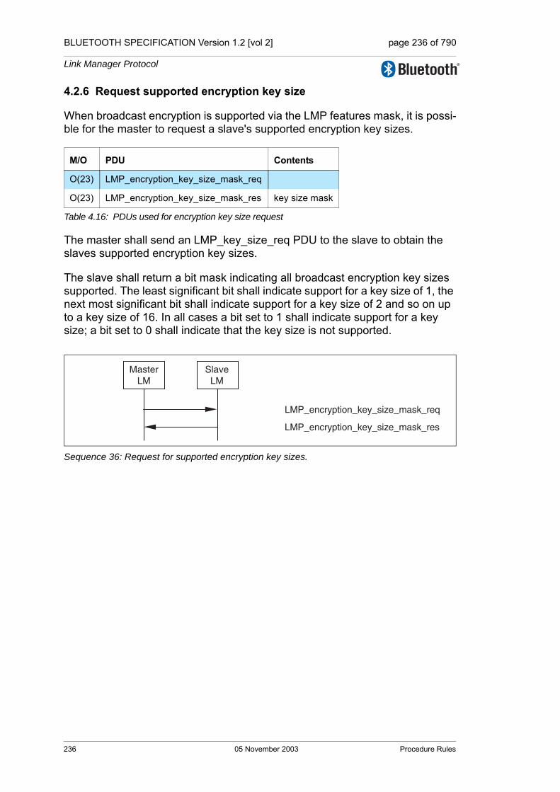
BLUETOOTH SPECIFICATION Version 1.2 [vol 2] page 236 of 790
Link Manager Protocol
4.2.6 Request supported encryption key size
When broadcast encryption is supported via the LMP features mask, it is possi-ble for the master to request a slave's supported encryption key sizes.
The master shall send an LMP_key_size_req PDU to the slave to obtain the slaves supported encryption key sizes.
The slave shall return a bit mask indicating all broadcast encryption key sizes supported. The least significant bit shall indicate support for a key size of 1, the next most significant bit shall indicate support for a key size of 2 and so on up to a key size of 16. In all cases a bit set to 1 shall indicate support for a key size; a bit set to 0 shall indicate that the key size is not supported.
Sequence 36: Request for supported encryption key sizes.
M/O PDU Contents
O(23) LMP_encryption_key_size_mask_req
O(23) LMP_encryption_key_size_mask_res key size mask
Table 4.16: PDUs used for encryption key size request
LMP_encryption_key_size_mask_req
LMP_encryption_key_size_mask_res
MasterLM
SlaveLM
236 05 November 2003 Procedure Rules
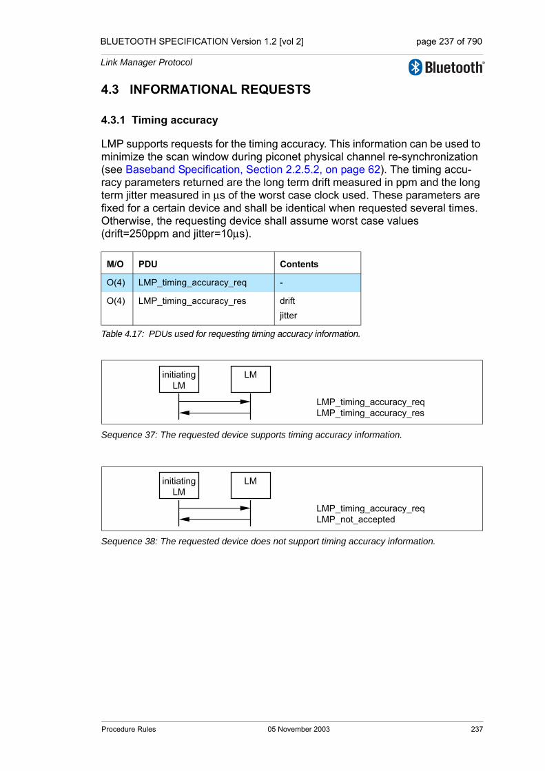
BLUETOOTH SPECIFICATION Version 1.2 [vol 2] page 237 of 790
Link Manager Protocol
4.3 INFORMATIONAL REQUESTS
4.3.1 Timing accuracy
LMP supports requests for the timing accuracy. This information can be used to minimize the scan window during piconet physical channel re-synchronization (see Baseband Specification, Section 2.2.5.2, on page 62). The timing accu-racy parameters returned are the long term drift measured in ppm and the long term jitter measured in µs of the worst case clock used. These parameters are fixed for a certain device and shall be identical when requested several times. Otherwise, the requesting device shall assume worst case values (drift=250ppm and jitter=10µs).
Sequence 37: The requested device supports timing accuracy information.
Sequence 38: The requested device does not support timing accuracy information.
M/O PDU Contents
O(4) LMP_timing_accuracy_req -
O(4) LMP_timing_accuracy_res driftjitter
Table 4.17: PDUs used for requesting timing accuracy information.
initiatingLM
LM
LMP_timing_accuracy_reqLMP_timing_accuracy_res
initiatingLM
LM
LMP_timing_accuracy_reqLMP_not_accepted
Procedure Rules 05 November 2003 237
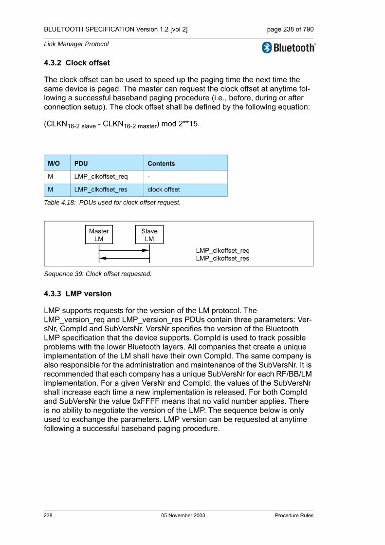
BLUETOOTH SPECIFICATION Version 1.2 [vol 2] page 238 of 790
Link Manager Protocol
4.3.2 Clock offset
The clock offset can be used to speed up the paging time the next time the same device is paged. The master can request the clock offset at anytime fol-lowing a successful baseband paging procedure (i.e., before, during or after connection setup). The clock offset shall be defined by the following equation:
(CLKN16-2 slave - CLKN16-2 master) mod 2**15.
Sequence 39: Clock offset requested.
4.3.3 LMP version
LMP supports requests for the version of the LM protocol. The LMP_version_req and LMP_version_res PDUs contain three parameters: Ver-sNr, CompId and SubVersNr. VersNr specifies the version of the Bluetooth LMP specification that the device supports. CompId is used to track possible problems with the lower Bluetooth layers. All companies that create a unique implementation of the LM shall have their own CompId. The same company is also responsible for the administration and maintenance of the SubVersNr. It is recommended that each company has a unique SubVersNr for each RF/BB/LM implementation. For a given VersNr and CompId, the values of the SubVersNr shall increase each time a new implementation is released. For both CompId and SubVersNr the value 0xFFFF means that no valid number applies. There is no ability to negotiate the version of the LMP. The sequence below is only used to exchange the parameters. LMP version can be requested at anytime following a successful baseband paging procedure.
M/O PDU Contents
M LMP_clkoffset_req -
M LMP_clkoffset_res clock offset
Table 4.18: PDUs used for clock offset request.
MasterLM
SlaveLM
LMP_clkoffset_reqLMP_clkoffset_res
238 05 November 2003 Procedure Rules
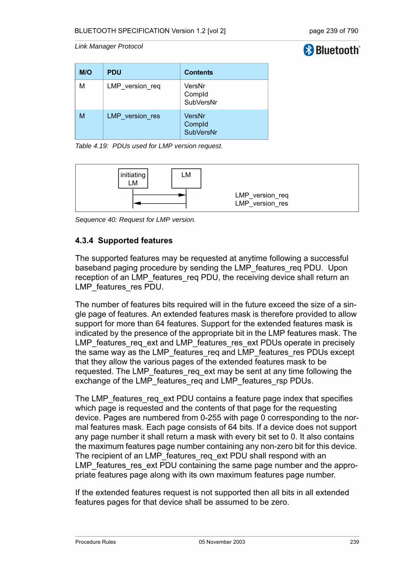
BLUETOOTH SPECIFICATION Version 1.2 [vol 2] page 239 of 790
Link Manager Protocol
Sequence 40: Request for LMP version.
4.3.4 Supported features
The supported features may be requested at anytime following a successful baseband paging procedure by sending the LMP_features_req PDU. Upon reception of an LMP_features_req PDU, the receiving device shall return an LMP_features_res PDU.
The number of features bits required will in the future exceed the size of a sin-gle page of features. An extended features mask is therefore provided to allow support for more than 64 features. Support for the extended features mask is indicated by the presence of the appropriate bit in the LMP features mask. The LMP_features_req_ext and LMP_features_res_ext PDUs operate in precisely the same way as the LMP_features_req and LMP_features_res PDUs except that they allow the various pages of the extended features mask to be requested. The LMP_features_req_ext may be sent at any time following the exchange of the LMP_features_req and LMP_features_rsp PDUs.
The LMP_features_req_ext PDU contains a feature page index that specifies which page is requested and the contents of that page for the requesting device. Pages are numbered from 0-255 with page 0 corresponding to the nor-mal features mask. Each page consists of 64 bits. If a device does not support any page number it shall return a mask with every bit set to 0. It also contains the maximum features page number containing any non-zero bit for this device. The recipient of an LMP_features_req_ext PDU shall respond with an LMP_features_res_ext PDU containing the same page number and the appro-priate features page along with its own maximum features page number.
If the extended features request is not supported then all bits in all extended features pages for that device shall be assumed to be zero.
M/O PDU Contents
M LMP_version_req VersNrCompIdSubVersNr
M LMP_version_res VersNrCompIdSubVersNr
Table 4.19: PDUs used for LMP version request.
initiatingLM
LM
LMP_version_reqLMP_version_res
Procedure Rules 05 November 2003 239
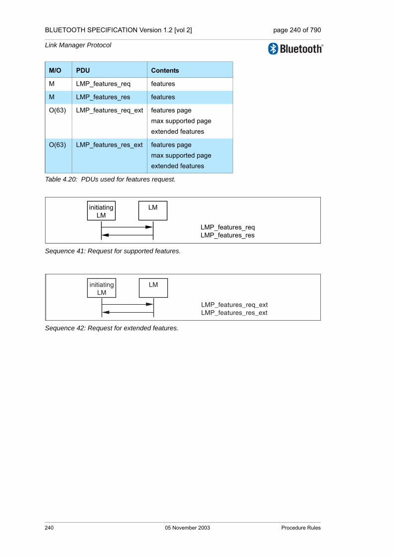
BLUETOOTH SPECIFICATION Version 1.2 [vol 2] page 240 of 790
Link Manager Protocol
Sequence 41: Request for supported features.
Sequence 42: Request for extended features.
M/O PDU Contents
M LMP_features_req features
M LMP_features_res features
O(63) LMP_features_req_ext features pagemax supported pageextended features
O(63) LMP_features_res_ext features pagemax supported pageextended features
Table 4.20: PDUs used for features request.
initiatingLM
LM
LMP_features_reqLMP_features_res
initiatingLM
LM
LMP_features_req_extLMP_features_res_ext
240 05 November 2003 Procedure Rules

BLUETOOTH SPECIFICATION Version 1.2 [vol 2] page 241 of 790
Link Manager Protocol
4.3.5 Name request
LMP supports name request to another device. The name is a user-friendly name associated with the device and consists of a maximum of 248 bytes coded according to the UTF-8 standard. The name is fragmented over one or more DM1 packets. When an LMP_name_req PDU is sent, a name offset indi-cates which fragment is expected. The corresponding LMP_name_res PDU carries the same name offset, the name length indicating the total number of bytes in the name of the device and the name fragment, where:• name fragment(N) = name(N + name offset), if (N + name offset) < name length• name fragment(N) = 0,otherwise.Here 0 ≤ N ≤ 13. In the first sent LMP_name_req PDU, name offset=0. Sequence 43 is then repeated until the initiator has collected all fragments of the name. The name request may be made at any time following a successful baseband paging procedure.
Sequence 43: Device’s name requested and it responses.
M/O PDU Contents
M LMP_name_req name offset
M LMP_name_res name offsetname lengthname fragment
Table 4.21: PDUs used for name request.
initiatingLM
LM
LMP_name_reqLMP_name_res
Procedure Rules 05 November 2003 241
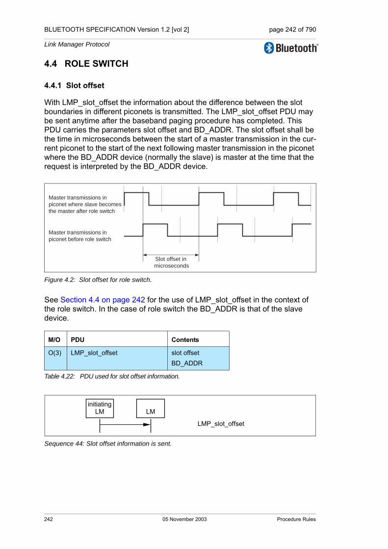
BLUETOOTH SPECIFICATION Version 1.2 [vol 2] page 242 of 790
Link Manager Protocol
4.4 ROLE SWITCH
4.4.1 Slot offset
With LMP_slot_offset the information about the difference between the slot boundaries in different piconets is transmitted. The LMP_slot_offset PDU may be sent anytime after the baseband paging procedure has completed. This PDU carries the parameters slot offset and BD_ADDR. The slot offset shall be the time in microseconds between the start of a master transmission in the cur-rent piconet to the start of the next following master transmission in the piconet where the BD_ADDR device (normally the slave) is master at the time that the request is interpreted by the BD_ADDR device.
Figure 4.2: Slot offset for role switch.
See Section 4.4 on page 242 for the use of LMP_slot_offset in the context of the role switch. In the case of role switch the BD_ADDR is that of the slave device.
Sequence 44: Slot offset information is sent.
M/O PDU Contents
O(3) LMP_slot_offset slot offsetBD_ADDR
Table 4.22: PDU used for slot offset information.
Slot offset in
microseconds
Master transmissions in
piconet where slave becomes
the master after role switch
Master transmissions in
piconet before role switch
initiatingLM LM
LMP_slot_offset
242 05 November 2003 Procedure Rules
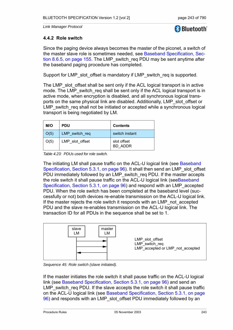
BLUETOOTH SPECIFICATION Version 1.2 [vol 2] page 243 of 790
Link Manager Protocol
4.4.2 Role switch
Since the paging device always becomes the master of the piconet, a switch of the master slave role is sometimes needed, see Baseband Specification, Sec-tion 8.6.5, on page 155. The LMP_switch_req PDU may be sent anytime after the baseband paging procedure has completed.
Support for LMP_slot_offset is mandatory if LMP_switch_req is supported.
The LMP_slot_offset shall be sent only if the ACL logical transport is in active mode. The LMP_switch_req shall be sent only if the ACL logical transport is in active mode, when encryption is disabled, and all synchronous logical trans-ports on the same physical link are disabled. Additionally, LMP_slot_offset or LMP_switch_req shall not be initiated or accepted while a synchronous logical transport is being negotiated by LM.
The initiating LM shall pause traffic on the ACL-U logical link (see Baseband Specification, Section 5.3.1, on page 96). It shall then send an LMP_slot_offset PDU immediately followed by an LMP_switch_req PDU. If the master accepts the role switch it shall pause traffic on the ACL-U logical link (seeBaseband Specification, Section 5.3.1, on page 96) and respond with an LMP_accepted PDU. When the role switch has been completed at the baseband level (suc-cessfully or not) both devices re-enable transmission on the ACL-U logical link. If the master rejects the role switch it responds with an LMP_not_accepted PDU and the slave re-enables transmission on the ACL-U logical link. The transaction ID for all PDUs in the sequence shall be set to 1.
Sequence 45: Role switch (slave initiated).
If the master initiates the role switch it shall pause traffic on the ACL-U logical link (see Baseband Specification, Section 5.3.1, on page 96) and send an LMP_switch_req PDU. If the slave accepts the role switch it shall pause traffic on the ACL-U logical link (see Baseband Specification, Section 5.3.1, on page 96) and responds with an LMP_slot_offset PDU immediately followed by an
M/O PDU Contents
O(5) LMP_switch_req switch instant
O(5) LMP_slot_offset slot offsetBD_ADDR
Table 4.23: PDUs used for role switch.
slave LM
masterLM
LMP_slot_offset LMP_switch_req LMP_accepted or LMP_not_accepted
Procedure Rules 05 November 2003 243

BLUETOOTH SPECIFICATION Version 1.2 [vol 2] page 244 of 790
Link Manager Protocol
LMP_accepted PDU. When the role switch has been completed at the base-band (successfully or not) both devices re-enable transmission on the ACL-U logical link. If the slave rejects the role switch it responds with an LMP_not_accepted PDU and the master re-enables transmission on the ACL-U logical link. The transaction ID for all PDUs in the sequence shall be set to 0.
Sequence 46: Role switch (master initiated).
The LMP_switch_req PDU contains a parameter, switch instant, which speci-fies the instant at which the TDD switch is performed. This is specified as a Bluetooth clock value of the master's clock, that is available to both devices. This instant is chosen by the sender of the message and shall be at least 2*Tpoll or 32 (whichever is greater) slots in the future. The switch instant shall be within 12 hours of the current clock value to avoid clock wrap.
The sender of the LMP_switch_req PDU selects the switch instant and queues the LMP_switch_req PDU to LC for transmission and starts a timer to expire at the switch instant. When the timer expires it initiates the mode switch. In the case of a master initiated switch if the LMP_slot_offset PDU has not been received by the switch instant the role switch is carried out without an estimate of the slave's slot offset. If an LMP_not_accepted PDU is received before the timer expires then the timer is stopped and the role switch shall not be initiated.
When the LMP_switch_req is received the switch instant is compared with the current master clock value. If it is in the past then the instant has been passed and an LMP_not_accepted PDU with the error code instant passed shall be returned. If it is in the future then an LMP_accepted PDU shall be returned assuming the role switch is allowed and a timer is started to expire at the switch instant. When this timer expires the role switch shall be initiated.
After a successful role switch the supervision timeout and poll interval (Tpoll) shall be set to their default values. The authentication state and the ACO shall remain unchanged. Adaptive Frequency Hopping shall follow the procedures described in Baseband Specification, Section 8.6.5, on page 155. The default value for max_slots shall be used.
master LM
slave LM
LMP_switch_req LMP_slot_offset (if LMP_accepted) LMP_accepted or LMP_not_accepted
244 05 November 2003 Procedure Rules
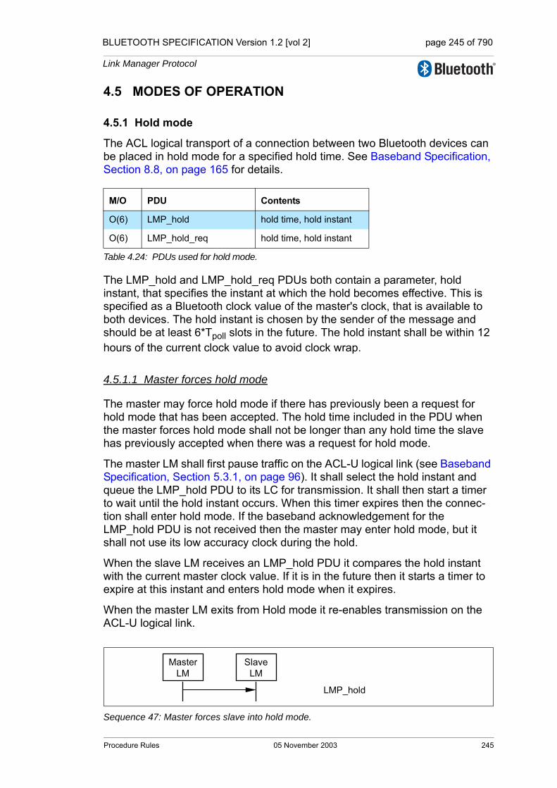
BLUETOOTH SPECIFICATION Version 1.2 [vol 2] page 245 of 790
Link Manager Protocol
4.5 MODES OF OPERATION
4.5.1 Hold mode
The ACL logical transport of a connection between two Bluetooth devices can be placed in hold mode for a specified hold time. See Baseband Specification, Section 8.8, on page 165 for details.
The LMP_hold and LMP_hold_req PDUs both contain a parameter, hold instant, that specifies the instant at which the hold becomes effective. This is specified as a Bluetooth clock value of the master's clock, that is available to both devices. The hold instant is chosen by the sender of the message and should be at least 6*Tpoll slots in the future. The hold instant shall be within 12 hours of the current clock value to avoid clock wrap.
4.5.1.1 Master forces hold mode
The master may force hold mode if there has previously been a request for hold mode that has been accepted. The hold time included in the PDU when the master forces hold mode shall not be longer than any hold time the slave has previously accepted when there was a request for hold mode.
The master LM shall first pause traffic on the ACL-U logical link (see Baseband Specification, Section 5.3.1, on page 96). It shall select the hold instant and queue the LMP_hold PDU to its LC for transmission. It shall then start a timer to wait until the hold instant occurs. When this timer expires then the connec-tion shall enter hold mode. If the baseband acknowledgement for the LMP_hold PDU is not received then the master may enter hold mode, but it shall not use its low accuracy clock during the hold.
When the slave LM receives an LMP_hold PDU it compares the hold instant with the current master clock value. If it is in the future then it starts a timer to expire at this instant and enters hold mode when it expires.
When the master LM exits from Hold mode it re-enables transmission on the ACL-U logical link.
Sequence 47: Master forces slave into hold mode.
M/O PDU Contents
O(6) LMP_hold hold time, hold instant
O(6) LMP_hold_req hold time, hold instant
Table 4.24: PDUs used for hold mode.
MasterLM
SlaveLM
LMP_hold
Procedure Rules 05 November 2003 245
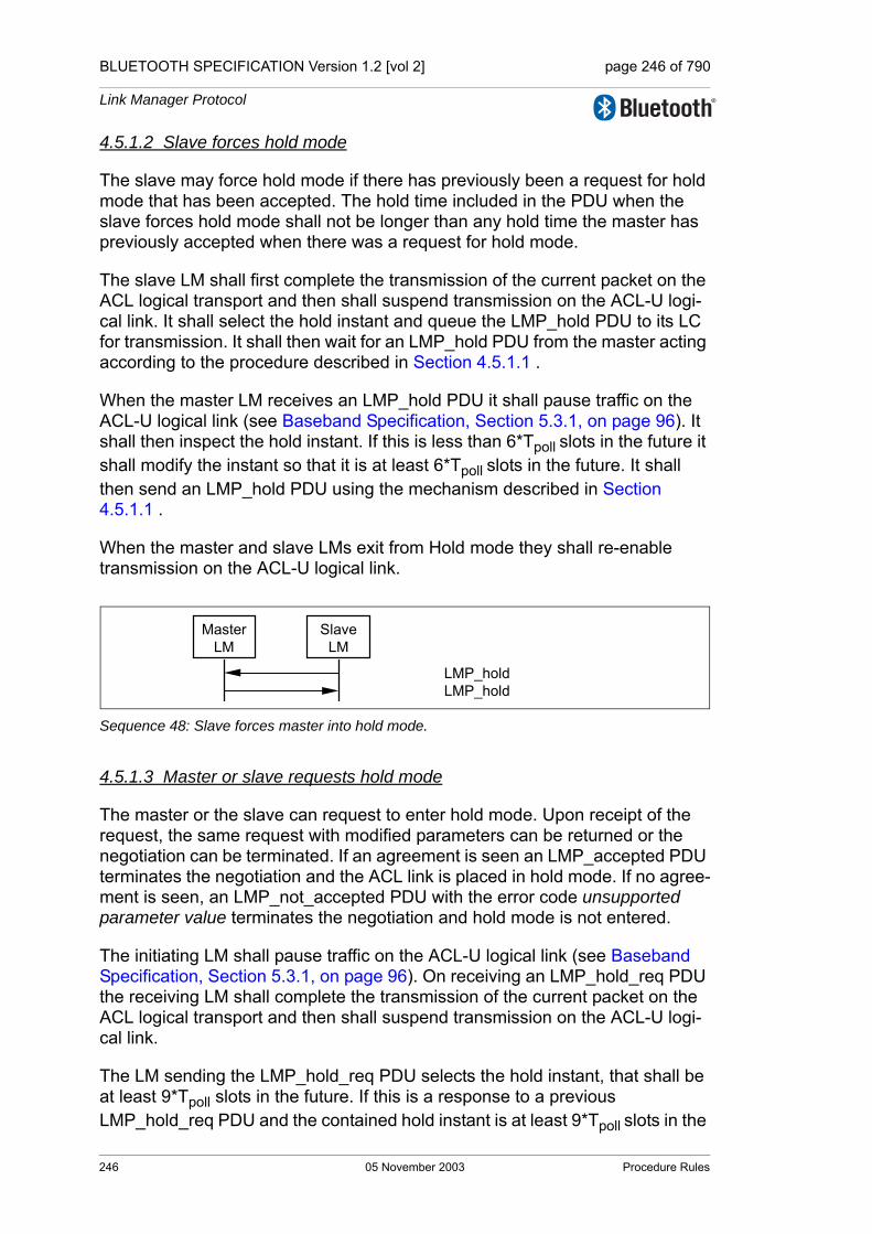
BLUETOOTH SPECIFICATION Version 1.2 [vol 2] page 246 of 790
Link Manager Protocol
4.5.1.2 Slave forces hold mode
The slave may force hold mode if there has previously been a request for hold mode that has been accepted. The hold time included in the PDU when the slave forces hold mode shall not be longer than any hold time the master has previously accepted when there was a request for hold mode.
The slave LM shall first complete the transmission of the current packet on the ACL logical transport and then shall suspend transmission on the ACL-U logi-cal link. It shall select the hold instant and queue the LMP_hold PDU to its LC for transmission. It shall then wait for an LMP_hold PDU from the master acting according to the procedure described in Section 4.5.1.1 .
When the master LM receives an LMP_hold PDU it shall pause traffic on the ACL-U logical link (see Baseband Specification, Section 5.3.1, on page 96). It shall then inspect the hold instant. If this is less than 6*Tpoll slots in the future it shall modify the instant so that it is at least 6*Tpoll slots in the future. It shall then send an LMP_hold PDU using the mechanism described in Section 4.5.1.1 .
When the master and slave LMs exit from Hold mode they shall re-enable transmission on the ACL-U logical link.
Sequence 48: Slave forces master into hold mode.
4.5.1.3 Master or slave requests hold mode
The master or the slave can request to enter hold mode. Upon receipt of the request, the same request with modified parameters can be returned or the negotiation can be terminated. If an agreement is seen an LMP_accepted PDU terminates the negotiation and the ACL link is placed in hold mode. If no agree-ment is seen, an LMP_not_accepted PDU with the error code unsupported parameter value terminates the negotiation and hold mode is not entered.
The initiating LM shall pause traffic on the ACL-U logical link (see Baseband Specification, Section 5.3.1, on page 96). On receiving an LMP_hold_req PDU the receiving LM shall complete the transmission of the current packet on the ACL logical transport and then shall suspend transmission on the ACL-U logi-cal link.
The LM sending the LMP_hold_req PDU selects the hold instant, that shall be at least 9*Tpoll slots in the future. If this is a response to a previous LMP_hold_req PDU and the contained hold instant is at least 9*Tpoll slots in the
MasterLM
SlaveLM
LMP_holdLMP_hold
246 05 November 2003 Procedure Rules

BLUETOOTH SPECIFICATION Version 1.2 [vol 2] page 247 of 790
Link Manager Protocol
future then this shall be used. The LMP_hold_req PDU shall then be queued to its LC for transmission and a timer shall be started to expire at this instant and the connection enters hold mode when it expires unless an LMP_not_accepted or LMP_hold_req PDU is received by its LM before that point. If the LM receiv-ing LMP_hold_req PDU agrees to enter hold mode it shall return an LMP_accepted PDU and shall start a timer to expire at the hold instant. When this timer expires it enters hold mode.
When each LM exits from Hold mode it shall re-enable transmission on the ACL-U logical link.
Sequence 49: Negotiation for hold mode.
4.5.2 Park state
If a slave does not need to participate in the channel, but should still remain synchronized to the master, it may be placed in park state. See Baseband Specification, Section 8.9, on page 165 for details.
Note: to keep a parked slave connected the master shall periodically unpark and repark the slave if the supervision timeout is not set to zero (see Baseband Specification, Section 3.1, on page 83).
All PDUs sent from the master to parked slaves are carried on the PSB-C logi-cal link (LMP link of parked slave broadcast logical transport). These PDUs, LMP_set_broadcast_scan_window, LMP_modify_beacon, LMP_unpark_BD_addr_req and LMP_unpark_PM_addr_req, are the only PDUs that shall be sent to a slave in park state and the only PDUs that shall be broadcast. To increase reliability for broadcast, the packets are as short as possible. Therefore the format for these LMP PDUs are somewhat different. The parameters are not always byte-aligned and the length of the PDUs is vari-able.
The messages for controlling park state include parameters, defined in Base-band Specification, Section 8.9, on page 165. When a slave is placed in park state it is assigned a unique PM_ADDR, that can be used by the master to unpark that slave. The all-zero PM_ADDR has a special meaning; it is not a valid PM_ADDR. If a device is assigned this PM_ADDR, it shall be identified with its BD_ADDR when it is unparked by the master.
initiatingLM LM
LMP_hold_reqLMP_hold_reqLMP_hold_req
LMP_accepted or LMP_not_accepted
Procedure Rules 05 November 2003 247

BLUETOOTH SPECIFICATION Version 1.2 [vol 2] page 248 of 790
Link Manager Protocol
M/O PDU Contents
O(8) LMP_park_req
timing control flags DBTB NB ∆B PM_ADDR AR_ADDR NBsleep DBsleep Daccess Taccess Nacc-slots Npoll Maccess access scheme
O(8) LMP_set_broadcast_scan_windowtiming control flags DB (optional)broadcast scan window
O(8) LMP_modify_beacon
timing control flags DB (optional)TB NB ∆B Daccess Taccess Nacc-slots NpollMaccess access scheme
Table 4.25: PDUs used for park state.
248 05 November 2003 Procedure Rules
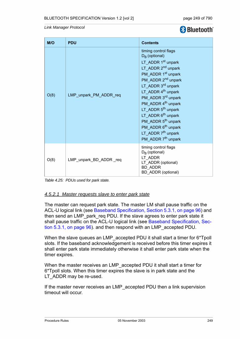
BLUETOOTH SPECIFICATION Version 1.2 [vol 2] page 249 of 790
Link Manager Protocol
4.5.2.1 Master requests slave to enter park state
The master can request park state. The master LM shall pause traffic on the ACL-U logical link (see Baseband Specification, Section 5.3.1, on page 96) and then send an LMP_park_req PDU. If the slave agrees to enter park state it shall pause traffic on the ACL-U logical link (see Baseband Specification, Sec-tion 5.3.1, on page 96). and then respond with an LMP_accepted PDU.
When the slave queues an LMP_accepted PDU it shall start a timer for 6*Tpoll slots. If the baseband acknowledgement is received before this timer expires it shall enter park state immediately otherwise it shall enter park state when the timer expires.
When the master receives an LMP_accepted PDU it shall start a timer for 6*Tpoll slots. When this timer expires the slave is in park state and the LT_ADDR may be re-used.
If the master never receives an LMP_accepted PDU then a link supervision timeout will occur.
O(8) LMP_unpark_PM_ADDR_req
timing control flags DB (optional)LT_ADDR 1st unparkLT_ADDR 2nd unparkPM_ADDR 1st unparkPM_ADDR 2nd unparkLT_ADDR 3rd unparkLT_ADDR 4th unparkPM_ADDR 3rd unparkPM_ADDR 4th unparkLT_ADDR 5th unparkLT_ADDR 6th unparkPM_ADDR 5th unparkPM_ADDR 6th unparkLT_ADDR 7th unparkPM_ADDR 7th unpark
O(8) LMP_unpark_BD_ADDR _req
timing control flags DB (optional)LT_ADDRLT_ADDR (optional)BD_ADDRBD_ADDR (optional)
M/O PDU Contents
Table 4.25: PDUs used for park state.
Procedure Rules 05 November 2003 249
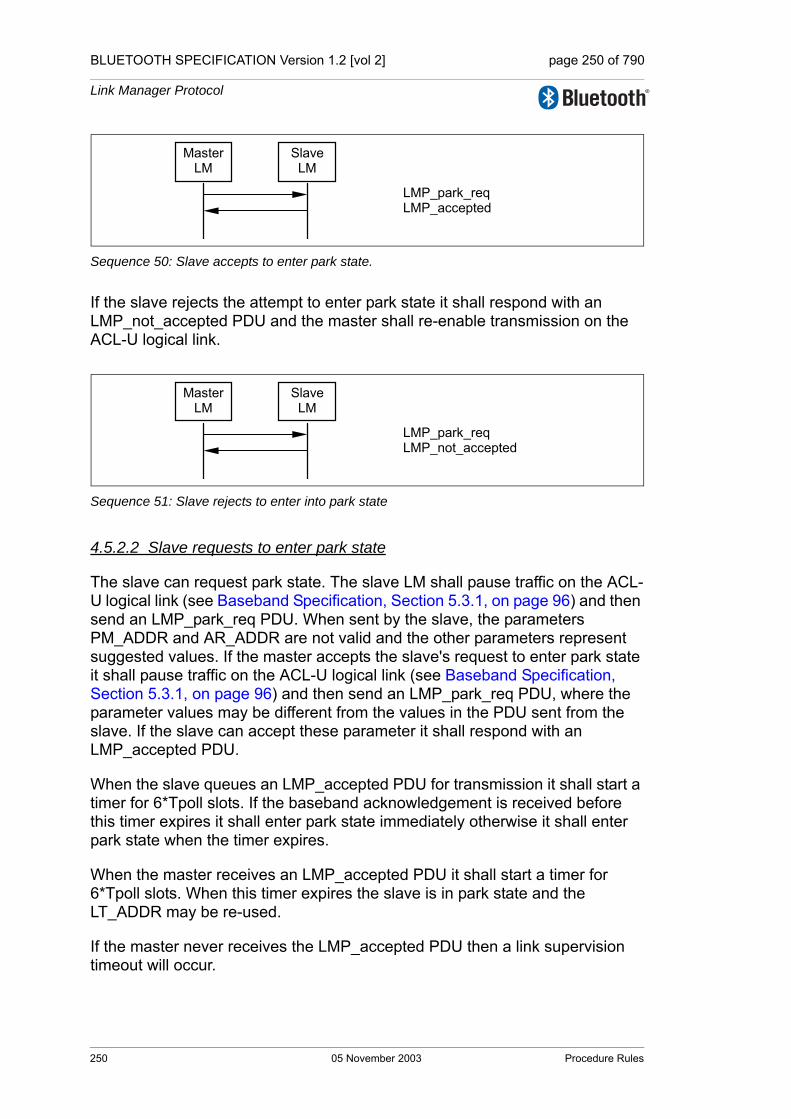
BLUETOOTH SPECIFICATION Version 1.2 [vol 2] page 250 of 790
Link Manager Protocol
Sequence 50: Slave accepts to enter park state.
If the slave rejects the attempt to enter park state it shall respond with an LMP_not_accepted PDU and the master shall re-enable transmission on the ACL-U logical link.
Sequence 51: Slave rejects to enter into park state
4.5.2.2 Slave requests to enter park state
The slave can request park state. The slave LM shall pause traffic on the ACL-U logical link (see Baseband Specification, Section 5.3.1, on page 96) and then send an LMP_park_req PDU. When sent by the slave, the parameters PM_ADDR and AR_ADDR are not valid and the other parameters represent suggested values. If the master accepts the slave's request to enter park state it shall pause traffic on the ACL-U logical link (see Baseband Specification, Section 5.3.1, on page 96) and then send an LMP_park_req PDU, where the parameter values may be different from the values in the PDU sent from the slave. If the slave can accept these parameter it shall respond with an LMP_accepted PDU.
When the slave queues an LMP_accepted PDU for transmission it shall start a timer for 6*Tpoll slots. If the baseband acknowledgement is received before this timer expires it shall enter park state immediately otherwise it shall enter park state when the timer expires.
When the master receives an LMP_accepted PDU it shall start a timer for 6*Tpoll slots. When this timer expires the slave is in park state and the LT_ADDR may be re-used.
If the master never receives the LMP_accepted PDU then a link supervision timeout will occur.
Master LM
Slave LM
LMP_park_req LMP_accepted
Master LM
Slave LM
LMP_park_req LMP_not_accepted
250 05 November 2003 Procedure Rules

BLUETOOTH SPECIFICATION Version 1.2 [vol 2] page 251 of 790
Link Manager Protocol
Sequence 52: Slave requests to enter park state and accepts master's beacon parameters.
If the master does not agree that the slave enters park state it shall send an LMP_not_accepted PDU. The slave shall then re-enable transmission on the ACL-U logical link.
Sequence 53: Master rejects slave's request to enter park state
If the slave does not accept the parameters in the LMP_park_req PDU sent from the master it shall respond with an LMP_not_accepted PDU and both devices shall re-enable transmission on the ACL-U logical link.
Sequence 54: Slave requests to enter park state, but rejects master's beacon parameters.
4.5.2.3 Master sets up broadcast scan window
If more broadcast capacity is needed than the beacon train, the master may indicate to the slaves that more broadcast information will follow the beacon train by sending an LMP_set_broadcast_scan_window PDU. This message shall be sent in a broadcast packet at the beacon slot(s). The scan window shall start in the beacon instant and shall only be valid for the current beacon.
Sequence 55: Master notifies all slaves of increase in broadcast capacity.
Master LM
Slave LM
LMP_park_req LMP_park_req LMP_accepted
Master LM
Slave LM
LMP_park_req LMP_not_accepted
Master LM
Slave LM
LMP_park_req LMP_park_req LMP_not_accepted
MasterLM
All slavesLM
LMP_set_broadcast_scan_window
Procedure Rules 05 November 2003 251
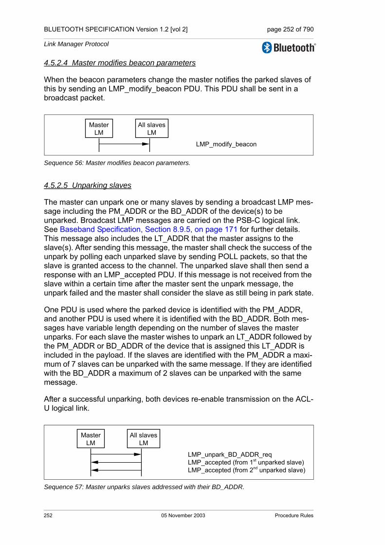
BLUETOOTH SPECIFICATION Version 1.2 [vol 2] page 252 of 790
Link Manager Protocol
4.5.2.4 Master modifies beacon parameters
When the beacon parameters change the master notifies the parked slaves of this by sending an LMP_modify_beacon PDU. This PDU shall be sent in a broadcast packet.
Sequence 56: Master modifies beacon parameters.
4.5.2.5 Unparking slaves
The master can unpark one or many slaves by sending a broadcast LMP mes-sage including the PM_ADDR or the BD_ADDR of the device(s) to be unparked. Broadcast LMP messages are carried on the PSB-C logical link. See Baseband Specification, Section 8.9.5, on page 171 for further details. This message also includes the LT_ADDR that the master assigns to the slave(s). After sending this message, the master shall check the success of the unpark by polling each unparked slave by sending POLL packets, so that the slave is granted access to the channel. The unparked slave shall then send a response with an LMP_accepted PDU. If this message is not received from the slave within a certain time after the master sent the unpark message, the unpark failed and the master shall consider the slave as still being in park state.
One PDU is used where the parked device is identified with the PM_ADDR, and another PDU is used where it is identified with the BD_ADDR. Both mes-sages have variable length depending on the number of slaves the master unparks. For each slave the master wishes to unpark an LT_ADDR followed by the PM_ADDR or BD_ADDR of the device that is assigned this LT_ADDR is included in the payload. If the slaves are identified with the PM_ADDR a maxi-mum of 7 slaves can be unparked with the same message. If they are identified with the BD_ADDR a maximum of 2 slaves can be unparked with the same message.
After a successful unparking, both devices re-enable transmission on the ACL-U logical link.
Sequence 57: Master unparks slaves addressed with their BD_ADDR.
MasterLM
All slavesLM
LMP_modify_beacon
MasterLM
All slavesLM
LMP_unpark_BD_ADDR_reqLMP_accepted (from 1st unparked slave)LMP_accepted (from 2nd unparked slave)
252 05 November 2003 Procedure Rules
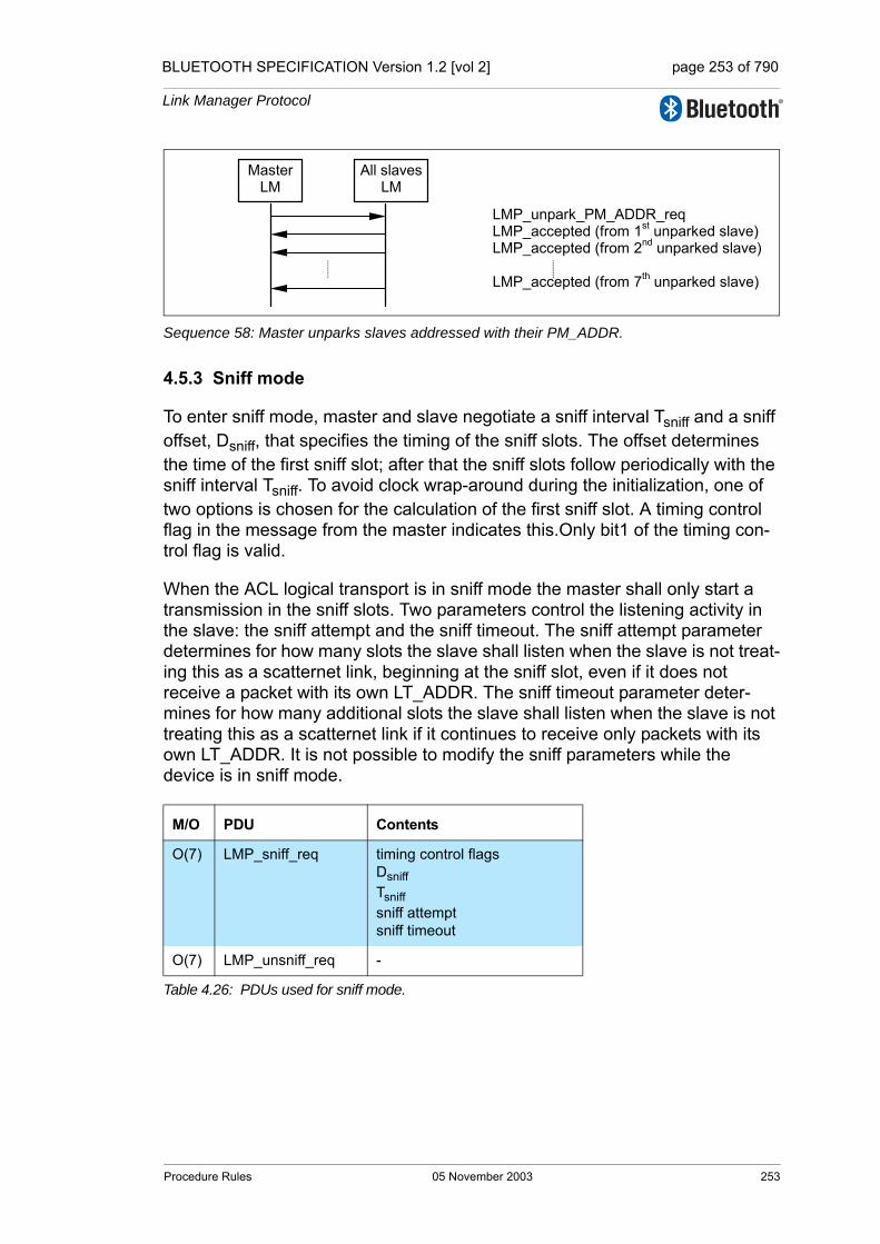
BLUETOOTH SPECIFICATION Version 1.2 [vol 2] page 253 of 790
Link Manager Protocol
Sequence 58: Master unparks slaves addressed with their PM_ADDR.
4.5.3 Sniff mode
To enter sniff mode, master and slave negotiate a sniff interval Tsniff and a sniff offset, Dsniff, that specifies the timing of the sniff slots. The offset determines the time of the first sniff slot; after that the sniff slots follow periodically with the sniff interval Tsniff. To avoid clock wrap-around during the initialization, one of two options is chosen for the calculation of the first sniff slot. A timing control flag in the message from the master indicates this.Only bit1 of the timing con-trol flag is valid.
When the ACL logical transport is in sniff mode the master shall only start a transmission in the sniff slots. Two parameters control the listening activity in the slave: the sniff attempt and the sniff timeout. The sniff attempt parameter determines for how many slots the slave shall listen when the slave is not treat-ing this as a scatternet link, beginning at the sniff slot, even if it does not receive a packet with its own LT_ADDR. The sniff timeout parameter deter-mines for how many additional slots the slave shall listen when the slave is not treating this as a scatternet link if it continues to receive only packets with its own LT_ADDR. It is not possible to modify the sniff parameters while the device is in sniff mode.
M/O PDU Contents
O(7) LMP_sniff_req timing control flagsDsniffTsniffsniff attemptsniff timeout
O(7) LMP_unsniff_req -
Table 4.26: PDUs used for sniff mode.
MasterLM
All slavesLM
LMP_unpark_PM_ADDR_reqLMP_accepted (from 1st unparked slave)LMP_accepted (from 2nd unparked slave)
LMP_accepted (from 7th unparked slave)
Procedure Rules 05 November 2003 253
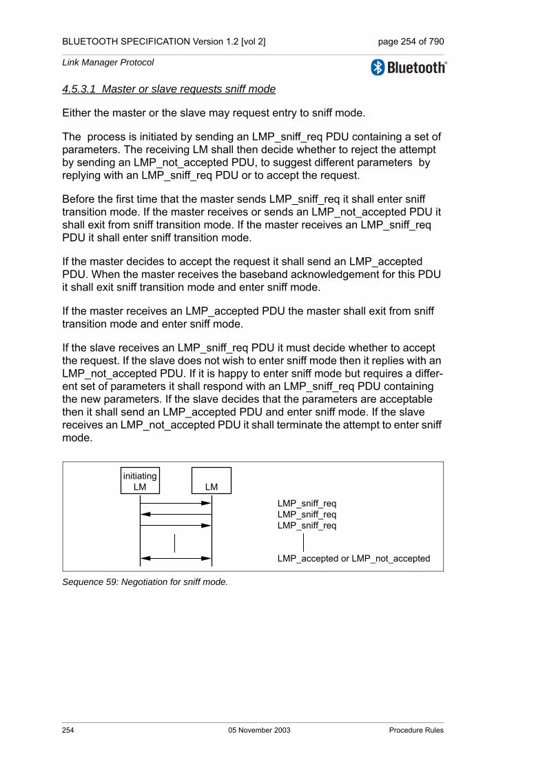
BLUETOOTH SPECIFICATION Version 1.2 [vol 2] page 254 of 790
Link Manager Protocol
4.5.3.1 Master or slave requests sniff mode
Either the master or the slave may request entry to sniff mode.
The process is initiated by sending an LMP_sniff_req PDU containing a set of parameters. The receiving LM shall then decide whether to reject the attempt by sending an LMP_not_accepted PDU, to suggest different parameters by replying with an LMP_sniff_req PDU or to accept the request.
Before the first time that the master sends LMP_sniff_req it shall enter sniff transition mode. If the master receives or sends an LMP_not_accepted PDU it shall exit from sniff transition mode. If the master receives an LMP_sniff_req PDU it shall enter sniff transition mode.
If the master decides to accept the request it shall send an LMP_accepted PDU. When the master receives the baseband acknowledgement for this PDU it shall exit sniff transition mode and enter sniff mode.
If the master receives an LMP_accepted PDU the master shall exit from sniff transition mode and enter sniff mode.
If the slave receives an LMP_sniff_req PDU it must decide whether to accept the request. If the slave does not wish to enter sniff mode then it replies with an LMP_not_accepted PDU. If it is happy to enter sniff mode but requires a differ-ent set of parameters it shall respond with an LMP_sniff_req PDU containing the new parameters. If the slave decides that the parameters are acceptable then it shall send an LMP_accepted PDU and enter sniff mode. If the slave receives an LMP_not_accepted PDU it shall terminate the attempt to enter sniff mode.
Sequence 59: Negotiation for sniff mode.
initiatingLM LM
LMP_sniff_reqLMP_sniff_reqLMP_sniff_req
LMP_accepted or LMP_not_accepted
254 05 November 2003 Procedure Rules
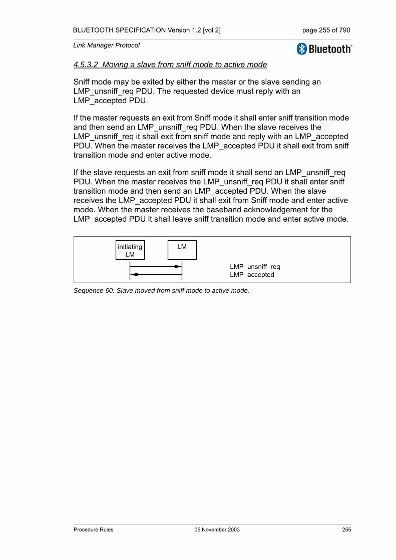
BLUETOOTH SPECIFICATION Version 1.2 [vol 2] page 255 of 790
Link Manager Protocol
4.5.3.2 Moving a slave from sniff mode to active mode
Sniff mode may be exited by either the master or the slave sending an LMP_unsniff_req PDU. The requested device must reply with an LMP_accepted PDU.
If the master requests an exit from Sniff mode it shall enter sniff transition mode and then send an LMP_unsniff_req PDU. When the slave receives the LMP_unsniff_req it shall exit from sniff mode and reply with an LMP_accepted PDU. When the master receives the LMP_accepted PDU it shall exit from sniff transition mode and enter active mode.
If the slave requests an exit from sniff mode it shall send an LMP_unsniff_req PDU. When the master receives the LMP_unsniff_req PDU it shall enter sniff transition mode and then send an LMP_accepted PDU. When the slave receives the LMP_accepted PDU it shall exit from Sniff mode and enter active mode. When the master receives the baseband acknowledgement for the LMP_accepted PDU it shall leave sniff transition mode and enter active mode.
Sequence 60: Slave moved from sniff mode to active mode.
initiatingLM
LM
LMP_unsniff_reqLMP_accepted
Procedure Rules 05 November 2003 255

BLUETOOTH SPECIFICATION Version 1.2 [vol 2] page 256 of 790
Link Manager Protocol
4.6 LOGICAL TRANSPORTS
When a connection is first established between two devices the connection consists of the default ACL logical links: ACL-C (for LMP messages) and ACL-U (for L2CAP data.) One or more synchronous logical transports (SCO or eSCO) may then be added. A new logical transport shall not be created if it would cause all slots to be allocated to reserved slots on secondary LT_ADDRs.
4.6.1 SCO logical transport
The SCO logical transport reserves slots separated by the SCO interval, Tsco. The first slot reserved for the SCO logical transport is defined by Tsco and the SCO offset, Dsco. See Baseband Specification, Section 8.6.2, on page 150 for details. A device shall initiate a request for HV2 or HV3 packet type only if the other device supports it (bits 12, 13) in its features mask. A device shall initiate CVSD, µ-law or A-law coding or uncoded (transparent) data only if the other device supports the corresponding feature. To avoid problems with a wrap-around of the clock during initialization of the SCO logical transport, the timing control flags parameter is used to indicate how the first SCO slot shall be calcu-lated. Only bit1 of the timing control flags parameter is valid. The SCO link is distinguished from all other SCO links by an SCO handle. The SCO handle zero shall not be used.
4.6.1.1 Master initiates an SCO link
When establishing an SCO link the master sends a request, a LMP_SCO_link_req PDU, with parameters that specify the timing, packet type and coding that will be used on the SCO link. Each of the SCO packet types supports three different voice coding formats on the air-interface: µ-law log PCM, A-law log PCM and CVSD. The air coding by log PCM or CVSD may be deactivated to achieve a transparent synchronous data link at 64 kbits/s.
The slots used for the SCO links are determined by three parameters controlled by the master: Tsco, Dsco and a flag indicating how the first SCO slot is calcu-lated. After the first slot, the SCO slots follow periodically at an interval of Tsco.
M/O PDU Contents
O(11) LMP_SCO_link_req
SCO handle timing control flags DscoTscoSCO packet air mode
O(11) LMP_remove_SCO_link_req SCO handleerror
Table 4.27: PDUs used for managing the SCO links.
256 05 November 2003 Procedure Rules

BLUETOOTH SPECIFICATION Version 1.2 [vol 2] page 257 of 790
Link Manager Protocol
If the slave does not accept the SCO link, but is willing to consider another pos-sible set of SCO parameters, it can indicate what it does not accept in the error code field of LMP_not_accepted PDU. The master may then issue a new request with modified parameters.
The SCO handle in the message shall be different from existing SCO link(s).
If the SCO packet type is HV1 the LMP_accepted shall be sent using the DM1 packet.
Sequence 61: Master requests an SCO link.
4.6.1.2 Slave initiates an SCO link
The slave may initiate the establishment of an SCO link. The slave sends an LMP_SCO_link_req PDU, but the parameters timing control flags and Dsco are invalid as well as the SCO handle, that shall be zero. If the master is not capa-ble of establishing an SCO link, it replies with an LMP_not_accepted PDU. Otherwise it sends back an LMP_SCO_link_req PDU. This message includes the assigned SCO handle, Dsco and the timing control flags. The master should try to use the same parameters as in the slave request; if the master cannot meet that request, it is allowed to use other values. The slave shall then reply with LMP_accepted or LMP_not_accepted PDU.
If the SCO packet type is HV1 the LMP_accepted shall be sent using the DM1 packet.
Sequence 62: Master rejects slave’s request for an SCO link.
Sequence 63: Master accepts slave’s request for an SCO link.
masterLM
slaveLM
LMP_SCO_link_reqLMP_accepted or LMP_not_accepted
masterLM
slaveLM
LMP_SCO_link_reqLMP_not_accepted
masterLM
slaveLM
LMP_SCO_link_reqLMP_SCO_link_reqLMP_accepted or LMP_not_accepted
Procedure Rules 05 November 2003 257

BLUETOOTH SPECIFICATION Version 1.2 [vol 2] page 258 of 790
Link Manager Protocol
4.6.1.3 Master requests change of SCO parameters
The master sends an LMP_SCO_link_req PDU, where the SCO handle is the handle of the SCO link the master wishes to change parameters for. If the slave accepts the new parameters, it replies with an LMP_accepted PDU and the SCO link will change to the new parameters. If the slave does not accept the new parameters, it shall reply with an LMP_not_accepted PDU and the SCO link is left unchanged. When the slave replies with an LMP_not_accepted PDU it shall indicate in the error code parameter what it does not accept. The master may then try to change the SCO link again with modified parameters. The sequence is the same as in Section 4.6.1.1 on page 256.
4.6.1.4 Slave requests change of SCO parameters
The slave sends an LMP_SCO_link_req PDU, where the SCO handle is the handle of the SCO link to be changed. The parameters timing control flags and Dsco are not valid in this PDU. If the master does not accept the new parame-ters it shall reply with an LMP_not_accpeted PDU and the SCO link is left unchanged. If the master accepts the new parameters it shall reply with an LMP_SCO_link_req PDU containing the same parameters as in the slave request. When receiving this message the slave replies with an LMP_not_accepted PDU if it does not accept the new parameters. The SCO link is then left unchanged. If the slave accepts the new parameters it replies with an LMP_accepted PDU and the SCO link will change to the new parame-ters. The sequence is the same as in Section 4.6.1.2 on page 257.
4.6.1.5 Remove an SCO link
Master or slave can remove the SCO link by sending a request including the SCO handle of the SCO link to be removed and an error code indicating why the SCO link is removed. The receiving side shall respond with an LMP_accepted PDU.
Sequence 64: SCO link removed.
initiatingLM LM
LMP_remove_SCO_link_reqLMP_accepted
258 05 November 2003 Procedure Rules
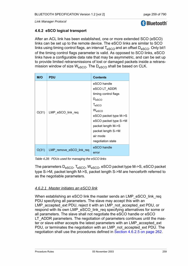
BLUETOOTH SPECIFICATION Version 1.2 [vol 2] page 259 of 790
Link Manager Protocol
4.6.2 eSCO logical transport
After an ACL link has been established, one or more extended SCO (eSCO) links can be set up to the remote device. The eSCO links are similar to SCO links using timing control flags, an interval TeSCO and an offset DeSCO. Only bit1 of the timing control flags parameter is valid. As opposed to SCO links, eSCO links have a configurable data rate that may be asymmetric, and can be set up to provide limited retransmissions of lost or damaged packets inside a retrans-mission window of size WeSCO. The DeSCO shall be based on CLK.
The parameters DeSCO, TeSCO, WeSCO, eSCO packet type M->S, eSCO packet type S->M, packet length M->S, packet length S->M are henceforth referred to as the negotiable parameters.
4.6.2.1 Master initiates an eSCO link
When establishing an eSCO link the master sends an LMP_eSCO_link_req PDU specifying all parameters. The slave may accept this with an LMP_accepted_ext PDU, reject it with an LMP_not_accepted_ext PDU, or respond with its own LMP_eSCO_link_req specifying alternatives for some or all parameters. The slave shall not negotiate the eSCO handle or eSCO LT_ADDR parameters. The negotiation of parameters continues until the mas-ter or slave either accepts the latest parameters with an LMP_accepted_ext PDU, or terminates the negotiation with an LMP_not_accepted_ext PDU. The negotiation shall use the procedures defined in Section 4.6.2.5 on page 262.
M/O PDU Contents
O(31) LMP_eSCO_link_req
eSCO handleeSCO LT_ADDRtiming control flagsDeSCO
TeSCO
WeSCO
eSCO packet type M->SeSCO packet type S->Mpacket length M->Spacket length S->Mair modenegotiation state
O(31) LMP_remove_eSCO_link_reqeSCO handleerror
Table 4.28: PDUs used for managing the eSCO links
Procedure Rules 05 November 2003 259
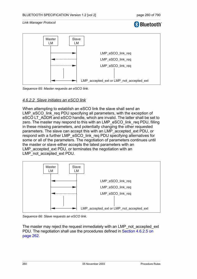
BLUETOOTH SPECIFICATION Version 1.2 [vol 2] page 260 of 790
Link Manager Protocol
Sequence 65: Master requests an eSCO link.
4.6.2.2 Slave initiates an eSCO link
When attempting to establish an eSCO link the slave shall send an LMP_eSCO_link_req PDU specifying all parameters, with the exception of eSCO LT_ADDR and eSCO handle, which are invalid. The latter shall be set to zero. The master may respond to this with an LMP_eSCO_link_req PDU, filling in these missing parameters, and potentially changing the other requested parameters. The slave can accept this with an LMP_accepted_ext PDU, or respond with a further LMP_eSCO_link_req PDU specifying alternatives for some or all of the parameters. The negotiation of parameters continues until the master or slave either accepts the latest parameters with an LMP_accepted_ext PDU, or terminates the negotiation with an LMP_not_accepted_ext PDU.
Sequence 66: Slave requests an eSCO link.
The master may reject the request immediately with an LMP_not_accepted_ext PDU. The negotiation shall use the procedures defined in Section 4.6.2.5 on page 262.
LMP_eSCO_link_req
LMP_eSCO_link_req
LMP_eSCO_link_req
LMP_accepted_ext or LMP_not_accepted_ext
MasterLM
SlaveLM
LMP_eSCO_link_req
LMP_eSCO_link_req
LMP_eSCO_link_req
LMP_accepted_ext or LMP_not_accepted_ext
MasterLM
SlaveLM
260 05 November 2003 Procedure Rules

BLUETOOTH SPECIFICATION Version 1.2 [vol 2] page 261 of 790
Link Manager Protocol
Sequence 67: Master rejects slave’s request for an eSCO link.
4.6.2.3 Master or slave requests change of eSCO parameters
The master or slave may request a renegotiation of the eSCO parameters. The master or slave shall send an LMP_eSCO_link_req PDU with the eSCO han-dle of the eSCO link the device wishes to renegotiate. The remote device may accept the changed parameters immediately with LMP_accepted_ext PDU, or the negotiation may be continued with further LMP_eSCO_link_req PDUs until the master or slave accepts the latest parameters with an LMP_accepted_ext PDU or terminates the negotation with an LMP_not_accepted_ext PDU. In the case of termination with an LMP_not_accepted_ext PDU, the eSCO link con-tinues on the previously negotiated parameters.
The sequence is the same as in Section 4.6.2.2 on page 260.
During re-negotiation, the eSCO LT_ADDR and eSCO handle shall not be re-negotiated and shall be set to the originally negotiated values. The negotiation shall use the procedures defined in Section 4.6.2.5 on page 262.
4.6.2.4 Remove an eSCO link
Either the master or slave may remove the eSCO link by sending a request including the eSCO handle of the eSCO link to be removed and a error code indicating why the eSCO link is removed. The receiving side shall respond with an LMP_accepted_ext PDU.
Sequence 68: eSCO link removed
LMP_eSCO_link_req
LMP_not_accepted_ext
MasterLM
SlaveLM
LMP_remove_eSCO_link_req
LMP_accepted_ext
initiatingLM
LM
Procedure Rules 05 November 2003 261

BLUETOOTH SPECIFICATION Version 1.2 [vol 2] page 262 of 790
Link Manager Protocol
4.6.2.5 Rules for the LMP negotiation and renegotiation
Rule 1: the negotiation_state shall be set to 0 by the initiating LM. After the ini-tial LMP_eSCO_link_req is sent the negotiation_state shall not be set to 0.
Rule 2: if the bandwidth (defined as 1600 times the packet length in bytes divided by TeSCO in slots) for either RX or TX or the air_mode cannot be accepted the device shall send LMP_not_accepted_ext with the appropriate error code.
Rule 3: Bandwidth and air_mode are not negotiable and shall not be changed for the duration of the negotiation. Once one side has rejected the negotiation (with LMP_not_accepted_ext) a new negotiation may be started with different bandwidth and air_mode parameters.
Rule 4: if the parameters will cause a latency violation (TeSCO + WeSCO + reserved synchronous slots > allowed local latency) the device should propose new parameters that shall not cause a reserved slot violation or latency viola-tion for the device that is sending the parameters. In this case the negotiation_state shall be set to 3. Otherwise the device shall send LMP_not_accepted_ext.
Rule 5: once a device has received an LMP_eSCO_link_req with the negotiation_state set to 3 (latency violation), the device shall not propose any combination of packet type, TeSCO, and WeSCO that will give an equal or larger latency than the combination that caused the latency violation for the other device.
Rule 6: if the parameters cause both a reserved slot violation and a latency violation the device shall set the negotiation_state to 3 (latency violation).
Rule 7: if the parameters will cause a reserved slot violation the device should propose new parameters that shall not cause a reserved slot violation. In this case the negotiation_state shall be set to 2. Otherwise the device shall send LMP_not_accepted_ext.
Rule 8: If the requested parameters are not supported the device should pro-pose a setting that is supported, and set the negotiation_state to 4. If it is not possible to find such a parameter set, the device shall send LMP_not_accepted_ext.
Rule 9: when proposing new parameters for reasons other than a latency vio-lation, reserved slot violation, or configuration not supported, the negotiation_state shall be set to 1.
262 05 November 2003 Procedure Rules

BLUETOOTH SPECIFICATION Version 1.2 [vol 2] page 263 of 790
Link Manager Protocol
4.6.2.6 Negotiation state definitions
Reserved Slot Violation: a reserved slot violation is when the receiving LM can-not setup the requested eSCO logical transport because the eSCO reserved slots would overlap with other regularly scheduled slots (e.g. other synchro-nous reserved slots, sniff instants, or park beacons).
Latency Violation: a latency violation is when the receiving LM cannot setup the requested eSCO logical transport because the latency (WeSCO+TeSCO + reserved synchronous slots) is greater than the maximum allowed latency.
Configuration not supported: The combination of parameters requested is not inside the supported range for the device.
Procedure Rules 05 November 2003 263
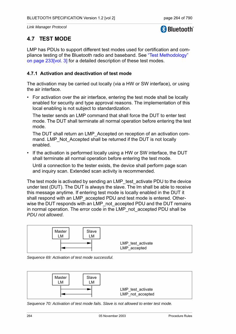
BLUETOOTH SPECIFICATION Version 1.2 [vol 2] page 264 of 790
Link Manager Protocol
4.7 TEST MODE
LMP has PDUs to support different test modes used for certification and com-pliance testing of the Bluetooth radio and baseband. See “Test Methodology” on page 233[vol. 3] for a detailed description of these test modes.
4.7.1 Activation and deactivation of test mode
The activation may be carried out locally (via a HW or SW interface), or using the air interface.
• For activation over the air interface, entering the test mode shall be locally enabled for security and type approval reasons. The implementation of this local enabling is not subject to standardization.The tester sends an LMP command that shall force the DUT to enter test mode. The DUT shall terminate all normal operation before entering the test mode.The DUT shall return an LMP_Accepted on reception of an activation com-mand. LMP_Not_Accepted shall be returned if the DUT is not locally enabled.
• If the activation is performed locally using a HW or SW interface, the DUT shall terminate all normal operation before entering the test mode. Until a connection to the tester exists, the device shall perform page scan and inquiry scan. Extended scan activity is recommended.
The test mode is activated by sending an LMP_test_activate PDU to the device under test (DUT). The DUT is always the slave. The lm shall be able to receive this message anytime. If entering test mode is locally enabled in the DUT it shall respond with an LMP_accepted PDU and test mode is entered. Other-wise the DUT responds with an LMP_not_accepted PDU and the DUT remains in normal operation. The error code in the LMP_not_accepted PDU shall be PDU not allowed.
Sequence 69: Activation of test mode successful.
Sequence 70: Activation of test mode fails. Slave is not allowed to enter test mode.
MasterLM
SlaveLM
LMP_test_activateLMP_accepted
MasterLM
SlaveLM
LMP_test_activateLMP_not_accepted
264 05 November 2003 Procedure Rules
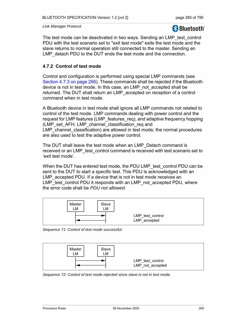
BLUETOOTH SPECIFICATION Version 1.2 [vol 2] page 265 of 790
Link Manager Protocol
The test mode can be deactivated in two ways. Sending an LMP_test_control PDU with the test scenario set to "exit test mode" exits the test mode and the slave returns to normal operation still connected to the master. Sending an LMP_detach PDU to the DUT ends the test mode and the connection.
4.7.2 Control of test mode
Control and configuration is performed using special LMP commands (see Section 4.7.3 on page 266). These commands shall be rejected if the Bluetooth device is not in test mode. In this case, an LMP_not_accepted shall be returned. The DUT shall return an LMP_accepted on reception of a control command when in test mode.
A Bluetooth device in test mode shall ignore all LMP commands not related to control of the test mode. LMP commands dealing with power control and the request for LMP features (LMP_features_req), and adaptive frequency hopping (LMP_set_AFH, LMP_channel_classification_req and LMP_channel_classification) are allowed in test mode; the normal procedures are also used to test the adaptive power control.
The DUT shall leave the test mode when an LMP_Detach command is received or an LMP_test_control command is received with test scenario set to ’exit test mode’.
When the DUT has entered test mode, the PDU LMP_test_control PDU can be sent to the DUT to start a specific test. This PDU is acknowledged with an LMP_accepted PDU. If a device that is not in test mode receives an LMP_test_control PDU it responds with an LMP_not_accepted PDU, where the error code shall be PDU not allowed.
Sequence 71: Control of test mode successful.
Sequence 72: Control of test mode rejected since slave is not in test mode.
MasterLM
SlaveLM
LMP_test_controlLMP_accepted
MasterLM
SlaveLM
LMP_test_controlLMP_not_accepted
Procedure Rules 05 November 2003 265
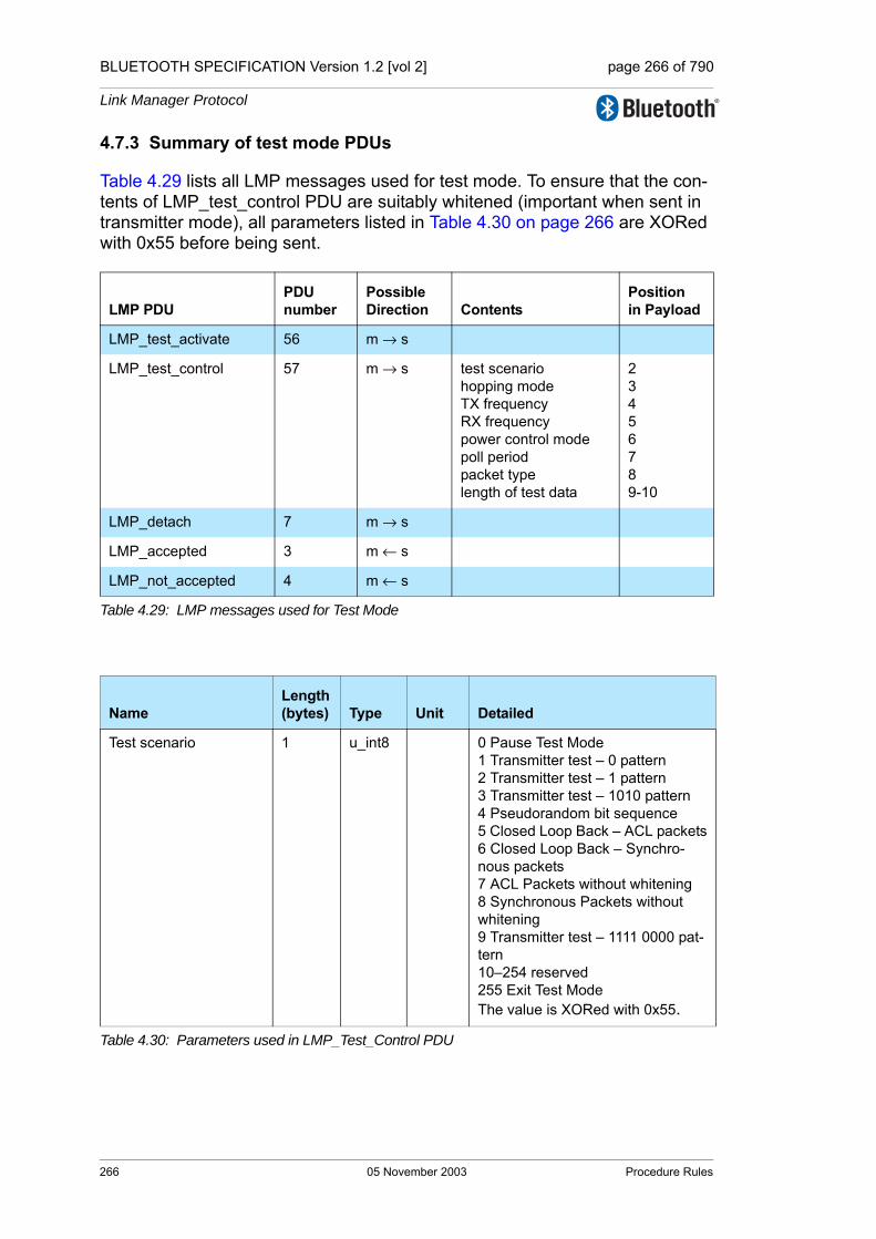
BLUETOOTH SPECIFICATION Version 1.2 [vol 2] page 266 of 790
Link Manager Protocol
4.7.3 Summary of test mode PDUs
Table 4.29 lists all LMP messages used for test mode. To ensure that the con-tents of LMP_test_control PDU are suitably whitened (important when sent in transmitter mode), all parameters listed in Table 4.30 on page 266 are XORed with 0x55 before being sent.
LMP PDUPDUnumber
PossibleDirection Contents
Positionin Payload
LMP_test_activate 56 m → s
LMP_test_control 57 m → s test scenariohopping modeTX frequencyRX frequencypower control modepoll period packet typelength of test data
23456789-10
LMP_detach 7 m → s
LMP_accepted 3 m ← s
LMP_not_accepted 4 m ← s
Table 4.29: LMP messages used for Test Mode
NameLength(bytes) Type Unit Detailed
Test scenario 1 u_int8 0 Pause Test Mode 1 Transmitter test – 0 pattern2 Transmitter test – 1 pattern3 Transmitter test – 1010 pattern4 Pseudorandom bit sequence5 Closed Loop Back – ACL packets6 Closed Loop Back – Synchro-nous packets7 ACL Packets without whitening8 Synchronous Packets without whitening9 Transmitter test – 1111 0000 pat-tern10–254 reserved255 Exit Test ModeThe value is XORed with 0x55.
Table 4.30: Parameters used in LMP_Test_Control PDU
266 05 November 2003 Procedure Rules
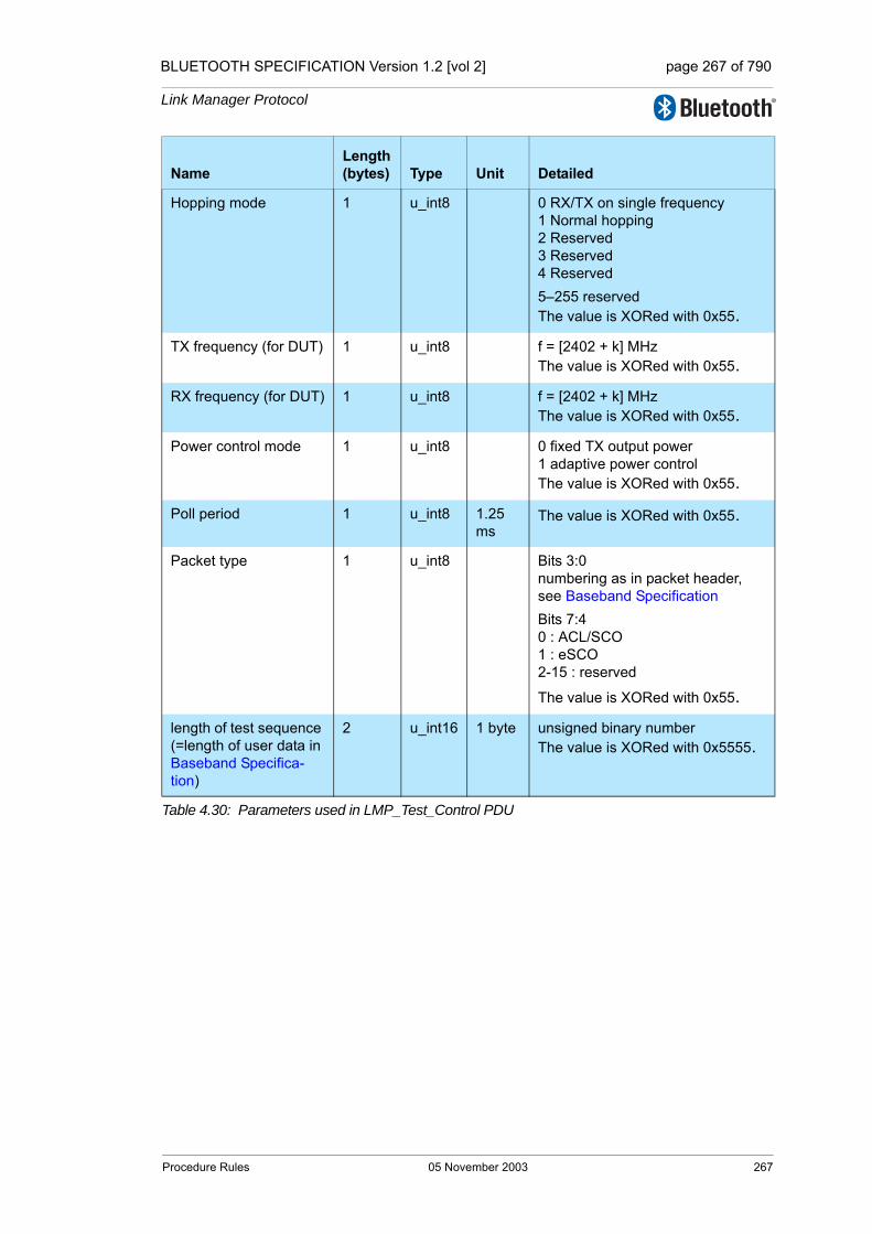
BLUETOOTH SPECIFICATION Version 1.2 [vol 2] page 267 of 790
Link Manager Protocol
Hopping mode 1 u_int8 0 RX/TX on single frequency1 Normal hopping 2 Reserved3 Reserved 4 Reserved 5–255 reservedThe value is XORed with 0x55.
TX frequency (for DUT) 1 u_int8 f = [2402 + k] MHzThe value is XORed with 0x55.
RX frequency (for DUT) 1 u_int8 f = [2402 + k] MHzThe value is XORed with 0x55.
Power control mode 1 u_int8 0 fixed TX output power1 adaptive power controlThe value is XORed with 0x55.
Poll period 1 u_int8 1.25 ms
The value is XORed with 0x55.
Packet type 1 u_int8 Bits 3:0 numbering as in packet header, see Baseband SpecificationBits 7:4 0 : ACL/SCO 1 : eSCO 2-15 : reserved
The value is XORed with 0x55.
length of test sequence (=length of user data in Baseband Specifica-tion)
2 u_int16 1 byte unsigned binary number The value is XORed with 0x5555.
NameLength(bytes) Type Unit Detailed
Table 4.30: Parameters used in LMP_Test_Control PDU
Procedure Rules 05 November 2003 267
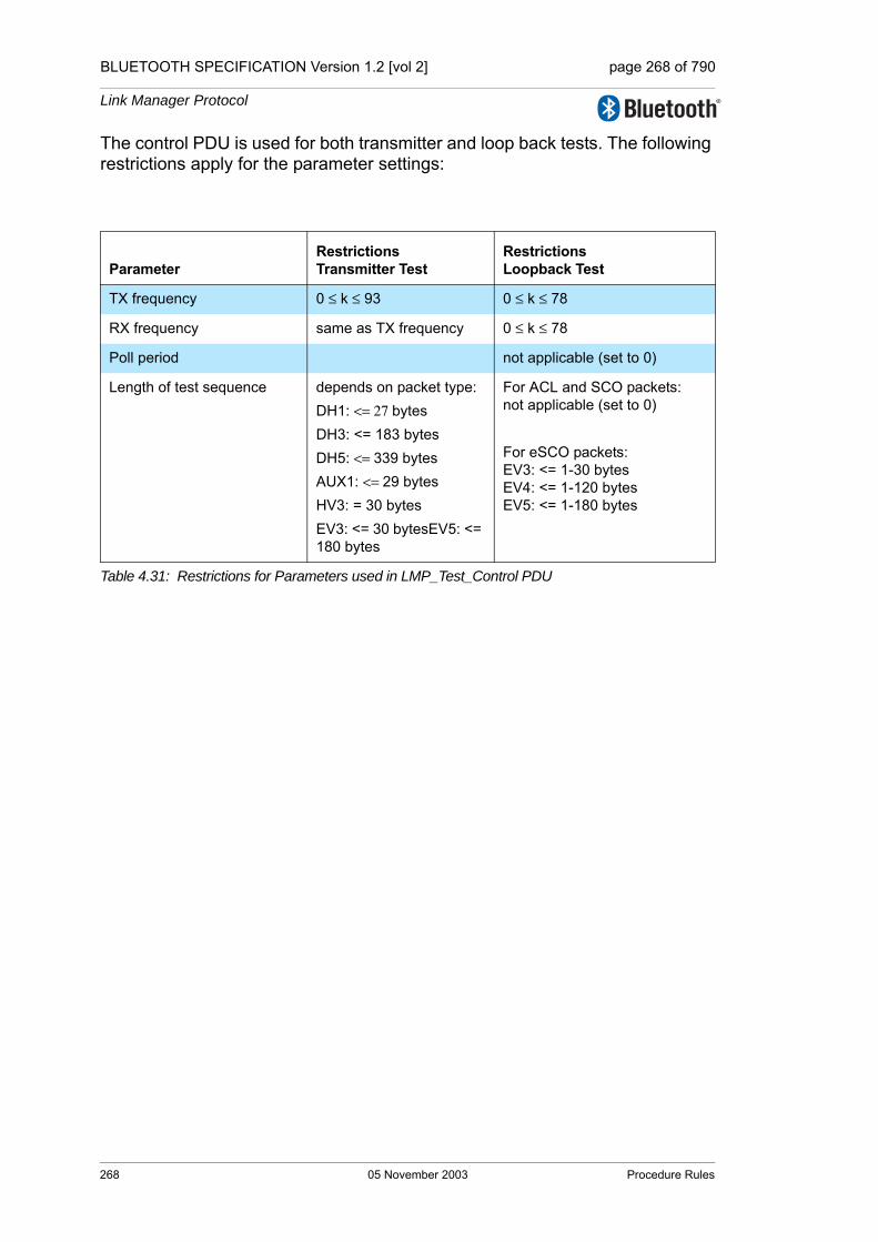
BLUETOOTH SPECIFICATION Version 1.2 [vol 2] page 268 of 790
Link Manager Protocol
The control PDU is used for both transmitter and loop back tests. The following restrictions apply for the parameter settings:
ParameterRestrictionsTransmitter Test
RestrictionsLoopback Test
TX frequency 0 ≤ k ≤ 93 0 ≤ k ≤ 78
RX frequency same as TX frequency 0 ≤ k ≤ 78
Poll period not applicable (set to 0)
Length of test sequence depends on packet type:DH1: <= 27 bytesDH3: <= 183 bytesDH5: <= 339 bytesAUX1: <= 29 bytesHV3: = 30 bytesEV3: <= 30 bytesEV5: <= 180 bytes
For ACL and SCO packets:not applicable (set to 0)
For eSCO packets: EV3: <= 1-30 bytesEV4: <= 1-120 bytesEV5: <= 1-180 bytes
Table 4.31: Restrictions for Parameters used in LMP_Test_Control PDU
268 05 November 2003 Procedure Rules

BLUETOOTH SPECIFICATION Version 1.2 [vol 2] page 269 of 790
Link Manager Protocol
5 SUMMARY
5.1 PDU SUMMARY
LMP PDU Length (bytes)
op code
Packet type
Possible direction Contents
Position in payload
Escape 1 variable 124 DM1 m ↔ sextended op code 2
variable 3-?
Escape 2 variable 125 DM1 m ↔ sextended op code 2
variable 3-?
Escape 3 variable 126 DM1 m ↔ sextended op code 2
variable 3-?
Escape 4 variable 127 DM1 m ↔ sextended op code 2
variable 3-?
LMP_accepted 2 3 DM1/DV m ↔ s op code 2
LMP_accepted_ext 4 127/01 DM1 m ↔ s
escape op code 3
extended op code 4
LMP_au_rand 17 11 DM1 m ↔ s random number 2-17
LMP_auto_rate 1 35 DM1/DV m ↔ s -
LMP_channel_classification_req 7 127/
16 DM1 m s
AFH_reporting_mode 3
AFH_min_interval 4-5
AFH_max_interval 6-7
LMP_channel_classification 12 127/
17 DM1 m ← s AFH_channel_classification 3 – 12
LMP_clkoffset_req 1 5 DM1/DV m → s -
LMP_clkoffset_res 3 6 DM1/DV m ← s clock offset 2–3
LMP_comb_key 17 9 DM1 m ↔ s random number 2-17
LMP_decr_power_req 2 32 DM1/DV m ↔ s for future use 2
LMP_detach 2 7 DM1/DV m ↔ s error code 2
Table 5.1: Coding of the different LM PDUs.
Summary 05 November 2003 269
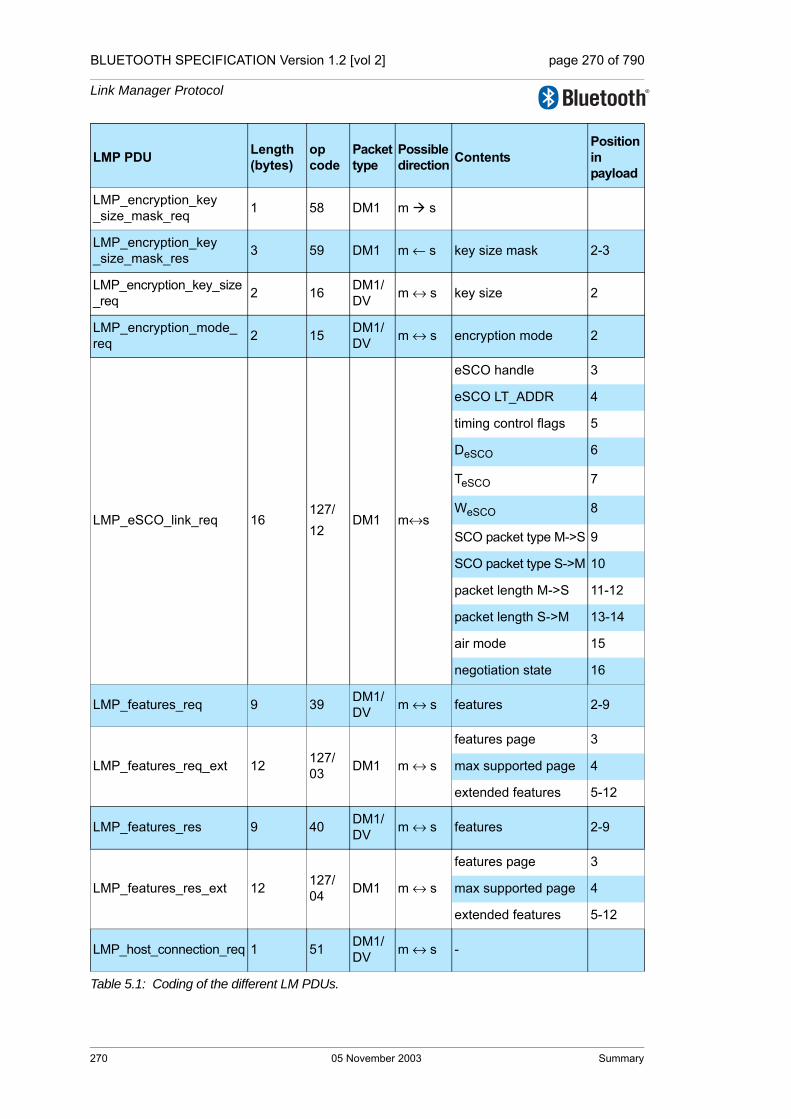
BLUETOOTH SPECIFICATION Version 1.2 [vol 2] page 270 of 790
Link Manager Protocol
LMP_encryption_key_size_mask_req 1 58 DM1 m s
LMP_encryption_key_size_mask_res 3 59 DM1 m ← s key size mask 2-3
LMP_encryption_key_size_req 2 16 DM1/
DV m ↔ s key size 2
LMP_encryption_mode_req 2 15 DM1/
DV m ↔ s encryption mode 2
LMP_eSCO_link_req 16127/12
DM1 m↔s
eSCO handle 3
eSCO LT_ADDR 4
timing control flags 5
DeSCO 6
TeSCO 7
WeSCO 8
SCO packet type M->S 9
SCO packet type S->M 10
packet length M->S 11-12
packet length S->M 13-14
air mode 15
negotiation state 16
LMP_features_req 9 39 DM1/DV m ↔ s features 2-9
LMP_features_req_ext 12 127/03 DM1 m ↔ s
features page 3
max supported page 4
extended features 5-12
LMP_features_res 9 40 DM1/DV m ↔ s features 2-9
LMP_features_res_ext 12 127/04 DM1 m ↔ s
features page 3
max supported page 4
extended features 5-12
LMP_host_connection_req 1 51 DM1/DV m ↔ s -
LMP PDU Length (bytes)
op code
Packet type
Possible direction Contents
Position in payload
Table 5.1: Coding of the different LM PDUs.
270 05 November 2003 Summary

BLUETOOTH SPECIFICATION Version 1.2 [vol 2] page 271 of 790
Link Manager Protocol
LMP_hold 7 20 DM1/DV m ↔ s
hold time 2-3
hold instant 4-7
LMP_hold_req 7 21 DM1/DV m ↔ s
hold time 2-3
hold instant 4-7
LMP_incr_power_req 2 31 DM1/DV m ↔ s for future use 2
LMP_in_rand 17 8 DM1 m ↔ s random number 2-17
LMP_max_power 1 33 DM1/DV m ↔ s -
LMP_max_slot 2 45 DM1/DV m ↔ s max slots 2
LMP_max_slot_req 2 46 DM1/DV m ↔ s max slots 2
LMP_min_power 1 34 DM1/DV m ↔ s -
LMP_modify_beacon11or 13
28 DM1 m → s
timing control flags 2
DB 3-4
TB 5-6
NB 7
∆B 8
Daccess 9
Taccess 10
Nacc-slots 11
Npoll 12
Maccess 13:0-3
access scheme 13:4-7
LMP_name_req 2 1 DM1/DV m ↔ s name offset 2
LMP_name_res 17 2 DM1 m ↔ s
name offset 2
name length 3
name fragment 4-17
LMP PDU Length (bytes)
op code
Packet type
Possible direction Contents
Position in payload
Table 5.1: Coding of the different LM PDUs.
Summary 05 November 2003 271

BLUETOOTH SPECIFICATION Version 1.2 [vol 2] page 272 of 790
Link Manager Protocol
LMP_not_accepted 3 4 DM1/DV m ↔ s
op code 2
error code 3
LMP_not_accepted_ext 5 127/02 DM1 m ↔ s
escape op code 3
extended op code 4
error code 5
LMP_page_mode_req 3 53 DM1/DV m ↔ s
paging scheme 2
paging scheme settings 3
LMP_page_scan_mode_req 3 54 DM1/
DV m ↔ spaging scheme 2
paging scheme settings 3
LMP_park_req 17 25 DM1 m ↔ s
timing control flags 2
DB 3-4
TB 5-6
NB 7
∆B 8
PM_ADDR 9
AR_ADDR 10
NBsleep 11
DBsleep 12
Daccess 13
Taccess 14
Nacc-slots 15
Npoll 16
Maccess 17:0-3
access scheme 17:4-7
LMP_preferred_rate 2 36 DM1/DV m ↔ s data rate 2
LMP_quality_of_service 4 41 DM1/DV m → s
poll interval 2-3
NBC 4
LMP_quality_of_service_req 4 42 DM1/
DV m ↔ spoll interval 2-3
NBC 4
LMP PDU Length (bytes)
op code
Packet type
Possible direction Contents
Position in payload
Table 5.1: Coding of the different LM PDUs.
272 05 November 2003 Summary

BLUETOOTH SPECIFICATION Version 1.2 [vol 2] page 273 of 790
Link Manager Protocol
LMP_remove_eSCO_link_req []see Note4 on page 276
4127/13
DM1 m↔seSCO handle 3
error code 4
LMP_remove_SCO_link_req 3 44 DM1/
DV m ↔ sSCO handle 2
error code 3
LMP_SCO_link_req 7 43 DM1/DV m ↔ s
SCO handle 2
timing control flags 3
Dsco 4
Tsco 5
SCO packet 6
air mode 7
LMP_set_AFH 16 60 DM1 m s
AFH_instant 2-5
AFH_mode 6
AFH_channel_map 7-16
LMP_set_broadcast_scan_window 4 or 6 27 DM1 m → s
timing control flags 2
DB 3-4
broadcast scan window 5-6
LMP_setup_complete 1 49 DM1 m ↔ s -
LMP_slot_offset 9 52 DM1/DV m ↔ s
slot offset 2-3
BD_ADDR 4-9
LMP_sniff_req 10 23 DM1 m ↔ s
timing control flags 2
Dsniff 3-4
Tsniff 5-6
sniff attempt 7-8
sniff timeout 9-10
LMP_sres 5 12 DM1/DV m ↔ s authentication response 2-5
LMP_start_encryption_req 17 17 DM1 m → s random number 2-17
LMP_stop_encryption_req 1 18 DM1/DV m → s -
LMP_supervision_timeout 3 55 DM1/DV m →s supervision timeout 2-3
LMP PDU Length (bytes)
op code
Packet type
Possible direction Contents
Position in payload
Table 5.1: Coding of the different LM PDUs.
Summary 05 November 2003 273
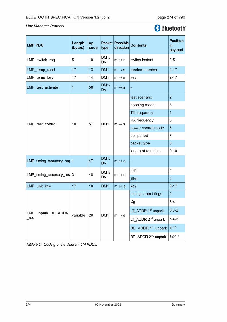
BLUETOOTH SPECIFICATION Version 1.2 [vol 2] page 274 of 790
Link Manager Protocol
LMP_switch_req 5 19 DM1/DV m ↔ s switch instant 2-5
LMP_temp_rand 17 13 DM1 m → s random number 2-17
LMP_temp_key 17 14 DM1 m → s key 2-17
LMP_test_activate 1 56 DM1/DV m → s -
LMP_test_control 10 57 DM1 m → s
test scenario 2
hopping mode 3
TX frequency 4
RX frequency 5
power control mode 6
poll period 7
packet type 8
length of test data 9-10
LMP_timing_accuracy_req 1 47 DM1/DV m ↔ s -
LMP_timing_accuracy_res 3 48 DM1/DV m ↔ s
drift 2
jitter 3
LMP_unit_key 17 10 DM1 m ↔ s key 2-17
LMP_unpark_BD_ADDR_req variable 29 DM1 m → s
timing control flags 2
DB 3-4
LT_ADDR 1st unpark 5:0-2
LT_ADDR 2nd unpark 5:4-6
BD_ADDR 1st unpark 6-11
BD_ADDR 2nd unpark 12-17
LMP PDU Length (bytes)
op code
Packet type
Possible direction Contents
Position in payload
Table 5.1: Coding of the different LM PDUs.
274 05 November 2003 Summary

BLUETOOTH SPECIFICATION Version 1.2 [vol 2] page 275 of 790
Link Manager Protocol
Note1: For LMP_set_broadcast_scan_window, LMP_modify_beacon, LMP_unpark_BD_ADDR_req and LMP_unpark_PM_ADDR_req the parameter DB is optional. This parameter is only present if bit0 of timing control flags is 1.
LMP_unpark_PM_ADDR_req variable 30 DM1 m → s
timing control flags 2
DB 3-4
LT_ADDR 1st unpark 5:0-3
LT_ADDR 2nd unpark 5:4-7
PM_ADDR 1st unpark 6
PM_ADDR 2nd unpark 7
LT_ADDR 3rd unpark 8:0-3
LT_ADDR 4th unpark 8:4-7
PM_ADDR 3rd unpark 9
PM_ADDR 4th unpark 10
LT_ADDR 5th unpark 11:0-3
LT_ADDR 6th unpark 11:4-7
PM_ADDR 6th unpark 12
PM_ADDR 6th unpark 13
LT_ADDR 7th unpark 14:0-3
PM_ADDR 7th unpark 15
LMP_unsniff_req 1 24 DM1/DV m ↔ s -
LMP_use_semi_permanent_key 1 50 DM1/
DV m → s -
LMP_version_req 6 37 DM1/DV m ↔ s
VersNr 2
CompId 3-4
SubVersNr 5-6
LMP_version_res 6 38 DM1/DV m ↔ s
VersNr 2
CompId 3-4
SubVersNr 5-6
LMP PDU Length (bytes)
op code
Packet type
Possible direction Contents
Position in payload
Table 5.1: Coding of the different LM PDUs.
Summary 05 November 2003 275

BLUETOOTH SPECIFICATION Version 1.2 [vol 2] page 276 of 790
Link Manager Protocol
If the parameter is not included, the position in payload for all parameters fol-lowing DB are decreased by 2.
Note2: For LMP_unpark_BD_ADDR the LT_ADDR and the BD_ADDR of the 2nd unparked slave are optional. If only one slave is unparked LT_ADDR 2nd unpark shall be zero and BD_ADDR 2nd unpark is left out.
Note3: For LMP_unpark_PM_ADDR the LT_ADDR and the PM_ADDR of the 2nd – 7th unparked slaves are optional. If N slaves are unparked, the fields up to and including the Nth unparked slave are present. If N is odd, the LT_ADDR (N+1)th unpark shall be zero. The length of the message is x + 3N/2 if N is even and x + 3(N+1)/2 -1 if N is odd, where x = 2 or 4 depending on if the DB is incluDed Or Not (See Note1).
Note4: Parameters coincide with their namesakes in LMP_<remove>_SCO_link_req apart from the following:
1. eSCO_LT_ADDR - the eSCO connection will be active on an additional LT_ADDR that needs to be defined. The master is allowed to re-assign an active eSCO link to a different LT_ADDR.
2. DeSCO, TeSCO - as per LMP_SCO_link_req but with a greater flexibility in values (e.g. no longer fixed with respect to HV1, HV2, and HV3 packet choice).
3. WeSCO - the eSCO retransmission window size (in slots)
4. packet type and packet length may be prescribed differently in Master-to-Slave or Slave-to-Master directions for asynchronous eSCO links
5. packet length (in bytes) - eSCO packet types no longer have fixed length
6. negotiation state – this is used to better enable the negotiation of the nego-tiable parameters: DeSCO, TeSCO, WeSCO, eSCO packet type M->S, eSCO packet type S->M, packet length M->S, packet length S->M. When responding to an eSCO link request with a new suggestion for these parameters, this flag may be set to 1 to indicate that the last received nego-tiable parameters are possible, but the new parameters specified in the response eSCO link request would be preferable, to 2 to indicate that the last received negotiable parameters are not possible as they cause a reserved slot violation or to 3 to indicate that the last received negotiable parameters would cause a latency violation. The flag shall be set to zero in the initiating LMP_eSCO_link_req.
276 05 November 2003 Summary
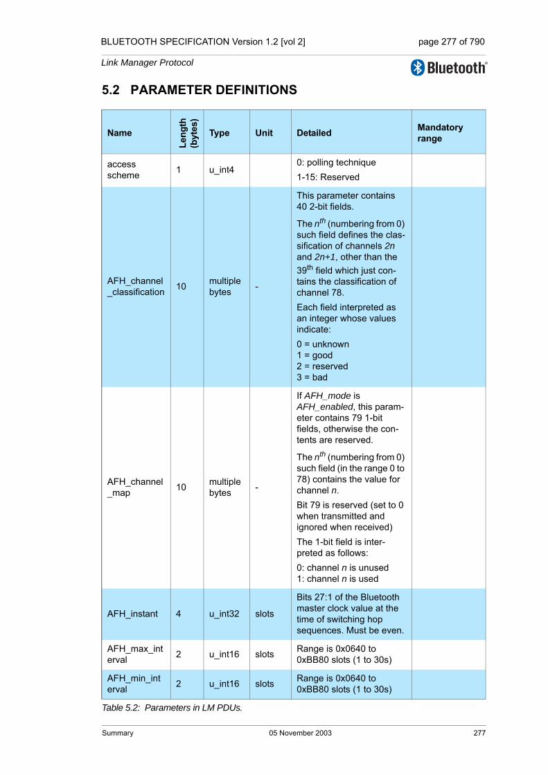
BLUETOOTH SPECIFICATION Version 1.2 [vol 2] page 277 of 790
Link Manager Protocol
5.2 PARAMETER DEFINITIONS
Name
Leng
th
(byt
es)
Type Unit Detailed Mandatory range
access scheme 1 u_int4
0: polling technique1-15: Reserved
AFH_channel_classification 10 multiple
bytes -
This parameter contains 40 2-bit fields.
The nth (numbering from 0) such field defines the clas-sification of channels 2n and 2n+1, other than the 39th field which just con-tains the classification of channel 78.Each field interpreted as an integer whose values indicate:0 = unknown1 = good2 = reserved3 = bad
AFH_channel_map 10 multiple
bytes -
If AFH_mode is AFH_enabled, this param-eter contains 79 1-bit fields, otherwise the con-tents are reserved.
The nth (numbering from 0) such field (in the range 0 to 78) contains the value for channel n.Bit 79 is reserved (set to 0 when transmitted and ignored when received)The 1-bit field is inter-preted as follows:0: channel n is unused1: channel n is used
AFH_instant 4 u_int32 slots
Bits 27:1 of the Bluetooth master clock value at the time of switching hop sequences. Must be even.
AFH_max_interval 2 u_int16 slots Range is 0x0640 to
0xBB80 slots (1 to 30s)
AFH_min_interval 2 u_int16 slots Range is 0x0640 to
0xBB80 slots (1 to 30s)
Table 5.2: Parameters in LM PDUs.
Summary 05 November 2003 277
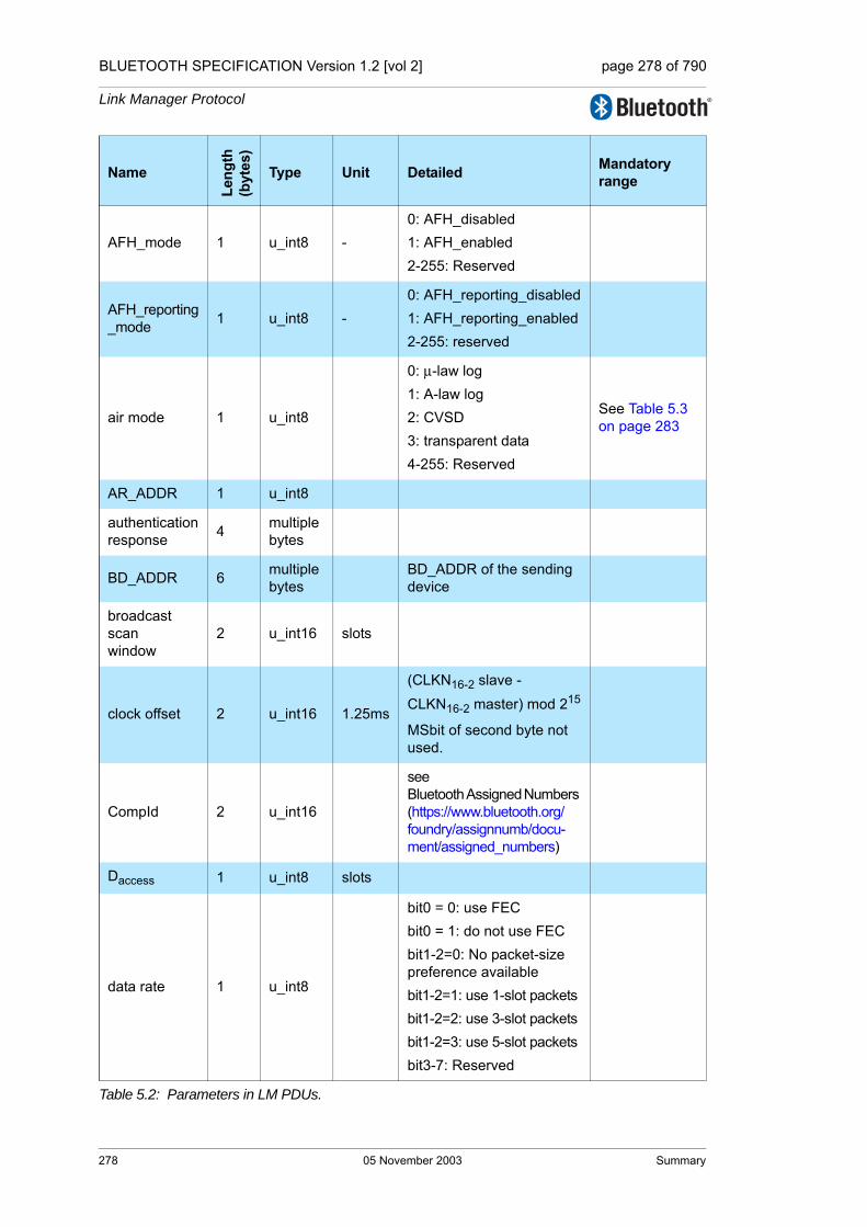
BLUETOOTH SPECIFICATION Version 1.2 [vol 2] page 278 of 790
Link Manager Protocol
AFH_mode 1 u_int8 -0: AFH_disabled1: AFH_enabled2-255: Reserved
AFH_reporting_mode 1 u_int8 -
0: AFH_reporting_disabled1: AFH_reporting_enabled2-255: reserved
air mode 1 u_int8
0: µ-law log1: A-law log2: CVSD 3: transparent data4-255: Reserved
See Table 5.3 on page 283
AR_ADDR 1 u_int8
authentication response 4 multiple
bytes
BD_ADDR 6 multiple bytes
BD_ADDR of the sending device
broadcast scanwindow
2 u_int16 slots
clock offset 2 u_int16 1.25ms
(CLKN16-2 slave - CLKN16-2 master) mod 215
MSbit of second byte not used.
CompId 2 u_int16
see Bluetooth Assigned Numbers (https://www.bluetooth.org/foundry/assignnumb/docu-ment/assigned_numbers)
Daccess 1 u_int8 slots
data rate 1 u_int8
bit0 = 0: use FECbit0 = 1: do not use FECbit1-2=0: No packet-size preference availablebit1-2=1: use 1-slot packetsbit1-2=2: use 3-slot packetsbit1-2=3: use 5-slot packetsbit3-7: Reserved
Name
Leng
th
(byt
es)
Type Unit Detailed Mandatory range
Table 5.2: Parameters in LM PDUs.
278 05 November 2003 Summary
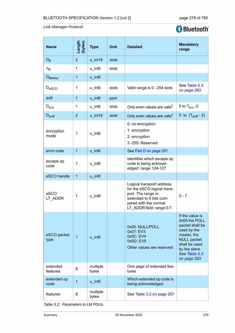
BLUETOOTH SPECIFICATION Version 1.2 [vol 2] page 279 of 790
Link Manager Protocol
DB 2 u_int16 slots
∆B 1 u_int8 slots
DBsleep 1 u_int8
DeSCO 1 u_int8 slots Valid range is 0 - 254 slots See Table 5.3 on page 283
drift 1 u_int8 ppm
Dsco 1 u_int8 slots Only even values are valid1 0 to Tsco -2
Dsniff 2 u_int16 slots Only even values are valid1 0 to (Tsniff - 2)
encryption mode 1 u_int8
0: no encryption1: encryption2: encryption 3 -255: Reserved
error code 1 u_int8 See Part D on page 291
escape op code 1 u_int8
Identifies which escape op code is being acknowl-edged: range 124-127
eSCO handle 1 u_int8
eSCO LT_ADDR 1 u_int8
Logical transport address for the eSCO logical trans-port. The range is extended to 8 bits com-pared with the normal LT_ADDR field: range 0-7.
0 - 7
eSCO packet type 1 u_int8
0x00: NULL/POLL0x07: EV30x0C: EV40x0D: EV5Other values are reserved
If the value is 0x00 the POLL packet shall be used by the master, the NULL packet shall be used by the slave. See Table 5.3 on page 283
extended features 8 multiple
bytesOne page of extended fea-tures
extended op code 1 u_int8 Which extended op code is
being acknowledged
features 8 multiple bytes See Table 3.2 on page 207
Name
Leng
th
(byt
es)
Type Unit Detailed Mandatory range
Table 5.2: Parameters in LM PDUs.
Summary 05 November 2003 279

BLUETOOTH SPECIFICATION Version 1.2 [vol 2] page 280 of 790
Link Manager Protocol
features page 1 u_int8
Identifies which page of extended features is being requested.0 means standard features1-255 other feature pages
hold instant 4 u_int32 slots Bits 27:1 of the master Bluetooth clock value
hold time 2 u_int16 slots Only even values are valid1
0x0014 to 0x8000; shall not exceed (supervisionTO * 0.999)
jitter 1 u_int8 µs
key 16 multiple bytes
key size 1 u_int8 byte
key size mask 2 u_int16
Bit mask of supported broadcast encryption key sizes: least significant bit is support for length 1, and so on. The bit shall be one if the key size is supported.
LT_ADDR 1 u_int4
Maccess 1 u_int4 number of access win-dows
max slots 1 u_int8 slots
max supported page
1 u_int8
Highest page of extended features which contains a non-zero bit for the originat-ing device. Range 0-255
Nacc-slots 1 u_int8 slots
name fragment 14 multiple
bytes UTF-8 characters.
name length 1 u_int8 bytes
name offset 1 u_int8 bytes
NB 1 u_int8
NBC 1 u_int8
NBsleep 1 u_int8
Name
Leng
th
(byt
es)
Type Unit Detailed Mandatory range
Table 5.2: Parameters in LM PDUs.
280 05 November 2003 Summary

BLUETOOTH SPECIFICATION Version 1.2 [vol 2] page 281 of 790
Link Manager Protocol
negotiation state 1 u_int8
0: Initiate negotiation1: the latest received set of negotiable parameters were possible but these parameters are preferred.2: the latest received set of negotiable parameters would cause a reserved slot violation.3: the latest received set of negotiable parameters would cause a latency vio-lation.4: the latest received set of of negotiable parameters are not supported. Other values are reserved
Npoll 1 u_int8
op code 1 u_int8
packet length 2 uint16 bytes
Length of the eSCO payload 0 for POLL/NULL1-30 for EV31-120 for EV41-180 for EV5Other values are invalid
See Table 5.3 on page 283
paging scheme 1 u_int8
0: mandatory scheme1-255: Reserved
paging scheme settings
1 u_int8
For mandatory scheme:0: R01: R12: R23-255: Reserved
PM_ADDR 1 u_int8
poll interval 2 u_int16 slots Only even values are valid1 0x0006 to 0x1000
random number 16 multiple
bytes
Name
Leng
th
(byt
es)
Type Unit Detailed Mandatory range
Table 5.2: Parameters in LM PDUs.
Summary 05 November 2003 281
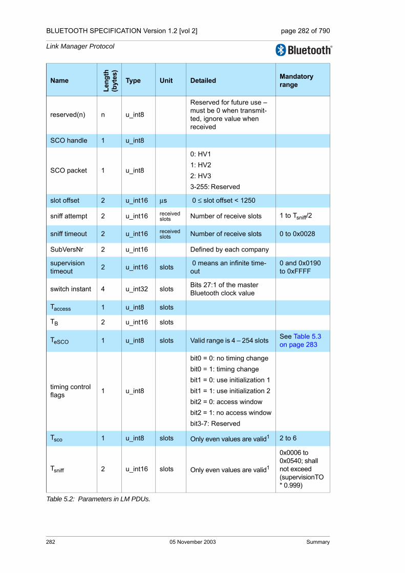
BLUETOOTH SPECIFICATION Version 1.2 [vol 2] page 282 of 790
Link Manager Protocol
reserved(n) n u_int8
Reserved for future use – must be 0 when transmit-ted, ignore value when received
SCO handle 1 u_int8
SCO packet 1 u_int8
0: HV1 1: HV2 2: HV3 3-255: Reserved
slot offset 2 u_int16 µs 0 ≤ slot offset < 1250
sniff attempt 2 u_int16 received slots Number of receive slots 1 to Tsniff/2
sniff timeout 2 u_int16 received slots Number of receive slots 0 to 0x0028
SubVersNr 2 u_int16 Defined by each company
supervision timeout 2 u_int16 slots 0 means an infinite time-
out0 and 0x0190 to 0xFFFF
switch instant 4 u_int32 slots Bits 27:1 of the master Bluetooth clock value
Taccess 1 u_int8 slots
TB 2 u_int16 slots
TeSCO 1 u_int8 slots Valid range is 4 – 254 slots See Table 5.3 on page 283
timing controlflags 1 u_int8
bit0 = 0: no timing changebit0 = 1: timing change bit1 = 0: use initialization 1bit1 = 1: use initialization 2bit2 = 0: access windowbit2 = 1: no access windowbit3-7: Reserved
Tsco 1 u_int8 slots Only even values are valid1 2 to 6
Tsniff 2 u_int16 slots Only even values are valid1
0x0006 to 0x0540; shall not exceed (supervisionTO * 0.999)
Name
Leng
th
(byt
es)
Type Unit Detailed Mandatory range
Table 5.2: Parameters in LM PDUs.
282 05 November 2003 Summary

BLUETOOTH SPECIFICATION Version 1.2 [vol 2] page 283 of 790
Link Manager Protocol
VersNr 1 u_int8
See Bluetooth Assigned Numbers, (http://www.blue-tooth.org/assigned-num-bers.htm)
WeSCO 1 u_int8 slotsNumber of slots in the retransmission windowValid range is 0 – 254 slots
See Table 5.3 on page 283
1. If a device receives an LMP PDU with an odd value in this parameter field the PDU should be rejected with an error code of invalid LMP parameters.
EV3 EV4 EV5
DeSCO 0-4 (even) 0-14 (even) 0-14 (even)
TeSCO 6 16 (even) 16 (even)
WeSCO 0-4 (even) 0-6 (even) 0-6 (even)
eSCO packet type M->S EV3 EV3, EV4 EV3, EV5
eSCO packet type S->M EV3 EV3, EV4 EV3, EV5
packet length M->S 30 1-120 1-180
packet length S->M 30 1-120 1-180
air modeAt least one of A-law, mu-law, CVSD, transparent
transparent transparent
Table 5.3: Mandatory parameter ranges for eSCO packet types
Name
Leng
th
(byt
es)
Type Unit Detailed Mandatory range
Table 5.2: Parameters in LM PDUs.
Summary 05 November 2003 283

BLUETOOTH SPECIFICATION Version 1.2 [vol 2] page 284 of 790
Link Manager Protocol
5.3 DEFAULT VALUES
Devices shall use these values before anything else has been negotiated:
Parameter Value
AFH_mode AFH_disabled
AFH_reporting_mode AFH_reporting_disabled
drift 250
jitter 10
max slots 1
poll interval 40
Table 5.4: Default values.
284 05 November 2003 Summary

BLUETOOTH SPECIFICATION Version 1.2 [vol 2] page 285 of 790
Link Manager Protocol
6 LIST OF FIGURES
Figure 1.1: Link Manager Protocol signalling layer. ...................................195Figure 2.1: Transmission of a message from master to slave. .................198Figure 2.2: Payload body when LMP PDUs are sent. ...............................199Figure 2.3: Symbols used in sequence diagrams. ....................................201Figure 4.1: Connection establishment. ......................................................209Figure 4.2: Slot offset for role switch. ........................................................242
Sequence 1: Connection closed by sending LMP_detach. ......................211Sequence 2: A device requests a change of the other device’s TX power. ..212Sequence 3: The TX power cannot be increased. ...................................212Sequence 4: The TX power cannot be decreased. ..................................212Sequence 5: Master Enables AFH. ..........................................................214Sequence 6: Master disables AFH. .........................................................214Sequence 7: Master Updates AFH. .........................................................215Sequence 8: Channel classification reporting. .........................................217Sequence 9: Setting the link supervision timeout. ...................................218Sequence 10: A notifies B to enable CQDDR ............................................219
Sequence 11: B sends A a preferred packet type .....................................219Sequence 12: Master notifies slave of quality of service. ..........................220Sequence 13: Device accepts new quality of service ................................221Sequence 14: Device rejects new quality of service. .................................221Sequence 15: Negotiation for page mode. ................................................222Sequence 16: Negotiation for page scan mode .........................................222Sequence 17: Device allows Remote Device to use a maximum number of
slots. 223Sequence 18: Device requests a maximum number of slots. Remote Device
accepts. ..............................................................................223Sequence 19: Device requests a maximum number of slots. Remote Device
rejects. ................................................................................223Sequence 20: Authentication. Claimant has link key. ................................224
Sequence 21: Authentication fails. Claimant has no link key. ....................225Sequence 22: Pairing accepted. Responder has a variable PIN. Initiator has a
variable or fixed PIN. ..........................................................226Sequence 23: Responder has a fixed PIN and initiator has a variable PIN. 227Sequence 24: Both devices have a fixed PIN. ...........................................227Sequence 25: Responder rejects pairing. ..................................................227Sequence 26: Creation of the link key. ......................................................228Sequence 27: Successful change of the link key. ......................................229Sequence 28: Change of the link key not possible since the other device uses
List of Figures 05 November 2003 285

BLUETOOTH SPECIFICATION Version 1.2 [vol 2] page 286 of 790
Link Manager Protocol
a unit key. ...........................................................................229Sequence 29: Change to a temporary link key. .........................................230Sequence 30: Link key changed to the semi-permanent link key. .............231
Sequence 31: Negotiation for encryption mode. ........................................233Sequence 32: Encryption key size negotiation successful. .......................234Sequence 33: Encryption key size negotiation failed. ...............................234Sequence 34: Start of encryption. .............................................................234Sequence 35: Stop of encryption. ..............................................................235Sequence 36: Request for supported encryption key sizes. ......................236Sequence 37: The requested device supports timing accuracy information. .237Sequence 38: The requested device does not support timing accuracy infor-
mation. 237Sequence 39: Clock offset requested. .......................................................238Sequence 40: Request for LMP version. ...................................................239Sequence 41: Request for supported features. .........................................240Sequence 42: Request for extended features. ..........................................240
Sequence 43: Device’s name requested and it responses. .......................241Sequence 44: Slot offset information is sent. ............................................242Sequence 45: Role switch (slave initiated). ...............................................243Sequence 46: Role switch (master initiated). ............................................244Sequence 47: Master forces slave into hold mode. ...................................245Sequence 48: Slave forces master into hold mode. ..................................246Sequence 49: Negotiation for hold mode. .................................................247Sequence 50: Slave accepts to enter park state. ......................................250Sequence 51: Slave rejects to enter into park state ..................................250
Sequence 52: Slave requests to enter park state and accepts master's beacon parameters. ........................................................................251
Sequence 53: Master rejects slave's request to enter park state ..............251Sequence 54: Slave requests to enter park state, but rejects master's beacon
parameters. 251Sequence 55: Master notifies all slaves of increase in broadcast capacity. 251Sequence 56: Master modifies beacon parameters. .................................252Sequence 57: Master unparks slaves addressed with their BD_ADDR. ...252Sequence 58: Master unparks slaves addressed with their PM_ADDR. ...253Sequence 59: Negotiation for sniff mode. ..................................................254Sequence 60: Slave moved from sniff mode to active mode. ....................255Sequence 61: Master requests an SCO link. .............................................257Sequence 62: Master rejects slave’s request for an SCO link. ..................257Sequence 63: Master accepts slave’s request for an SCO link. ................257Sequence 64: SCO link removed. .............................................................258
286 05 November 2003 List of Figures

BLUETOOTH SPECIFICATION Version 1.2 [vol 2] page 287 of 790
Link Manager Protocol
Sequence 65: Master requests an eSCO link. ...........................................260Sequence 66: Slave requests an eSCO link. .............................................260
Sequence 67: Master rejects slave’s request for an eSCO link. ................261Sequence 68: eSCO link removed .............................................................261Sequence 69: Activation of test mode successful. .....................................264Sequence 70: Activation of test mode fails. Slave is not allowed to enter test
mode. ..................................................................................264Sequence 71: Control of test mode successful. .........................................265Sequence 72: Control of test mode rejected since slave is not in test mode. .265
List of Figures 05 November 2003 287

BLUETOOTH SPECIFICATION Version 1.2 [vol 2] page 288 of 790
Link Manager Protocol
288 05 November 2003 List of Figures

BLUETOOTH SPECIFICATION Version 1.2 [vol 2] page 289 of 790
Link Manager Protocol
7 LIST OF TABLES
Table 2.1: General response messages. ..................................................202Table 3.1: Feature definitions. ..................................................................203Table 3.2: Feature mask definition............................................................207Table 4.1: PDUs used for connection establishment. ...............................210Table 4.2: PDU used for detach................................................................210Table 4.3: PDUs used for power control. ..................................................211Table 4.4: PDUs used for AFH..................................................................213Table 4.5: PDUs used for Channel Classification Reporting.....................216Table 4.6: PDU used to set the supervision timeout. ................................218Table 4.7: PDUs used for quality driven change of the data rate.............219Table 4.8: PDUs used for quality of service. ............................................220Table 4.9: PDUs used to request paging scheme.....................................222Table 4.10: PDUs used to control the use of multi-slot packets..................223Table 4.11: PDUs used for authentication. .................................................224Table 4.12: PDUs used for pairing ..............................................................226Table 4.13: PDUs used for change of link key. ...........................................229Table 4.14: PDUs used to change the current link key. ..............................230Table 4.15: PDUs used for handling encryption..........................................232Table 4.16: PDUs used for encryption key size request .............................236Table 4.17: PDUs used for requesting timing accuracy information. ..........237Table 4.18: PDUs used for clock offset request..........................................238Table 4.19: PDUs used for LMP version request........................................239Table 4.20: PDUs used for features request...............................................240Table 4.21: PDUs used for name request...................................................241Table 4.22: PDU used for slot offset information. ......................................242Table 4.23: PDUs used for role switch........................................................243Table 4.24: PDUs used for hold mode. .......................................................245Table 4.25: PDUs used for park state. ........................................................248Table 4.26: PDUs used for sniff mode. .......................................................253Table 4.27: PDUs used for managing the SCO links. .................................256Table 4.28: PDUs used for managing the eSCO links ................................259Table 4.29: LMP messages used for Test Mode.........................................266Table 4.30: Parameters used in LMP_Test_Control PDU...........................266Table 4.31: Restrictions for Parameters used in LMP_Test_Control PDU..268Table 5.1: Coding of the different LM PDUs. ............................................269Table 5.2: Parameters in LM PDUs. .........................................................277Table 5.3: Mandatory parameter ranges for eSCO packet types..............283Table 5.4: Default values. .........................................................................284
List of Tables 05 November 2003 289

BLUETOOTH SPECIFICATION Version 1.2 [vol 2] page 290 of 790
Link Manager Protocol
290 05 November 2003 List of Tables

Core System Package [Controller volume]
Part DERROR CODES

BLUETOOTH SPECIFICATION Version 1.2 [vol 2] page 292 of 790
Error Codes
292 05 November 2003
BLUETOOTH SPECIFICATION Version 1.2 [vol 2] page 293 of 790
Error Codes
CONTENTS
1 Overview of Error Codes .................................................................2951.1 Usage Descriptions..................................................................2951.2 HCI Command Errors...............................................................2951.3 List of Error Codes ...................................................................296
2 Error Code Descriptions..................................................................2992.1 Unknown HCI Command (0X01)..............................................2992.2 Unknown Connection Identifier (0X02) ....................................2992.3 Hardware Failure (0X03)..........................................................2992.4 Page Timeout (0X04) ...............................................................2992.5 Authentication Failure (0X05)...................................................2992.6 PIN Missing (0X06) ..................................................................2992.7 Memory Capacity Exceeded (0X07) ........................................2992.8 Connection Timeout (0X08) .....................................................3002.9 Connection Limit Exceeded (0X09)..........................................3002.10 Synchronous Connection Limit to a Device Exceeded (0X0A) 3002.11 ACL Connection Already Exists (0X0B) ...................................3002.12 Command Disallowed (0X0C)..................................................3002.13 Connection Rejected due to Limited Resources (0X0D)..........3002.14 Connection Rejected due to Security Reasons (0X0E) ...........3002.15 Connection Rejected due to Unacceptable BD_ADDR (0X0F)3012.16 Connection Accept Timeout Exceeded (0X10) ........................3012.17 Unsupported Feature or Parameter Value (0X11)....................3012.18 Invalid HCI Command Parameters (0X12)...............................3012.19 Remote User Terminated Connection (0X13) ..........................3012.20 Remote Device Terminated Connection due to Low Resources
(0X14) ......................................................................................3022.21 Remote Device Terminated Connection due to Power Off
(0X15) ......................................................................................3022.22 Connection Terminated by Local Host (0X16)..........................3022.23 Repeated Attempts (0X17).......................................................3022.24 Pairing not Allowed (0X18).......................................................3022.25 Unknown LMP PDU (0X19) .....................................................3022.26 Unsupported Remote Feature (0X1A) .....................................3022.27 SCO Offset Rejected (0X1B) ...................................................3022.28 SCO Interval Rejected (0X1C) .................................................3032.29 SCO Air Mode Rejected (0X1D) ..............................................3032.30 INvalid LMP Parameters (0X1E)..............................................3032.31 Unspecified Error (0X1F) .........................................................3032.32 Unsupported LMP Parameter Value (0X20).............................3032.33 Role Change Not Allowed (0X21) ............................................303
05 November 2003 293
BLUETOOTH SPECIFICATION Version 1.2 [vol 2] page 294 of 790
Error Codes
2.34 LMP Response Timeout (0X22)...............................................3032.35 LMP Error Transaction Collision (0X23) ..................................3042.36 LMP PDU Not Allowed (0X24).................................................3042.37 Encryption Mode Not Acceptable (0X25).................................3042.38 Link Key Can Not be Changed (0X26) ....................................3042.39 Requested Qos is Not Supported (0X27) ................................3042.40 Instant Passed (0X28) .............................................................3042.41 Pairing with Unit Key Not Supported (0X29)............................3042.42 DIFFERENT TRANSACTION COLLISION (0X2A) .................3042.43 QoS Unacceptable Parameter (0X2C).....................................3042.44 QoS Rejected (0X2D) ..............................................................3052.45 Channel Classification Not Supported (0X2E).........................3052.46 Insufficient Security (0X2F)......................................................3052.47 Parameter out of Mandatory Range (0X30).............................3052.48 Role Switch Pending (0X32)....................................................3052.49 Reserved Slot Violation (0X34)................................................3052.50 Role Switch Failed (0X35) .......................................................305
294 05 November 2003

BLUETOOTH SPECIFICATION Version 1.2 [vol 2] page 295 of 790
Error Codes
1 OVERVIEW OF ERROR CODES
This document lists the various possible error codes. When a command fails, or an LMP message needs to indicate a failure, error codes are used to indi-cate the reason for the error. Error codes have a size of one octet.
1.1 USAGE DESCRIPTIONS
The purpose of this section is to give descriptions of how the error codes should be used. It is beyond the scope of this document to give detailed descriptions of all situations where error codes can be used, especially as this may be implementation dependent.
1.2 HCI COMMAND ERRORS
If an HCI Command that should generate an HCI_Command_Complete event generates an error then this error shall be reported in the HCI_Command_Complete event.
If an HCI Command that sent an HCI_Command_Status with the error code ‘Success’ to the host before processing may find an error during execution then the error may be reported in the normal completion command for the original command or in an HCI_Command_Status event.
Some HCI Commands may generate errors that need to be reported to be host, but there is insufficient information to determine how the command would normally be processed. In this case, two events can be used to indicate this to the host, the HCI_Command_Complete event and HCI_Command_Status events. Which of the two events is used is implementation-dependent.
Overview of Error Codes 05 November 2003 295
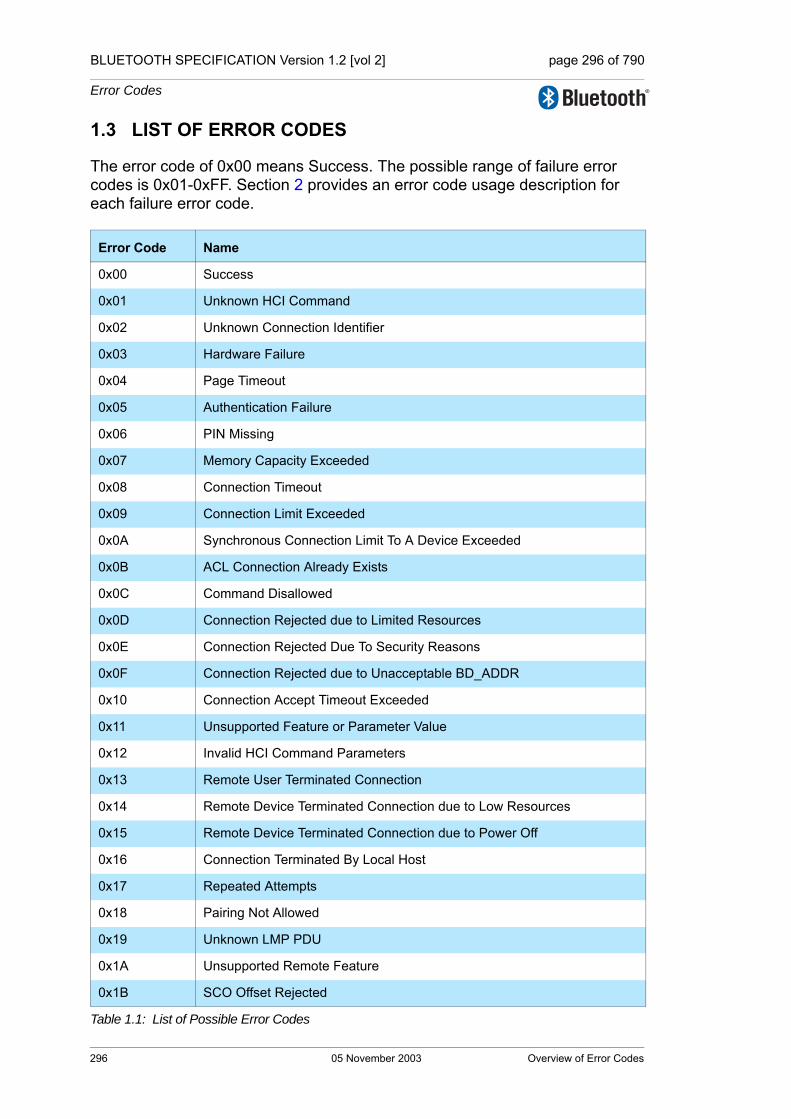
BLUETOOTH SPECIFICATION Version 1.2 [vol 2] page 296 of 790
Error Codes
1.3 LIST OF ERROR CODES
The error code of 0x00 means Success. The possible range of failure error codes is 0x01-0xFF. Section 2 provides an error code usage description for each failure error code.
Error Code Name
0x00 Success
0x01 Unknown HCI Command
0x02 Unknown Connection Identifier
0x03 Hardware Failure
0x04 Page Timeout
0x05 Authentication Failure
0x06 PIN Missing
0x07 Memory Capacity Exceeded
0x08 Connection Timeout
0x09 Connection Limit Exceeded
0x0A Synchronous Connection Limit To A Device Exceeded
0x0B ACL Connection Already Exists
0x0C Command Disallowed
0x0D Connection Rejected due to Limited Resources
0x0E Connection Rejected Due To Security Reasons
0x0F Connection Rejected due to Unacceptable BD_ADDR
0x10 Connection Accept Timeout Exceeded
0x11 Unsupported Feature or Parameter Value
0x12 Invalid HCI Command Parameters
0x13 Remote User Terminated Connection
0x14 Remote Device Terminated Connection due to Low Resources
0x15 Remote Device Terminated Connection due to Power Off
0x16 Connection Terminated By Local Host
0x17 Repeated Attempts
0x18 Pairing Not Allowed
0x19 Unknown LMP PDU
0x1A Unsupported Remote Feature
0x1B SCO Offset Rejected
Table 1.1: List of Possible Error Codes
296 05 November 2003 Overview of Error Codes

BLUETOOTH SPECIFICATION Version 1.2 [vol 2] page 297 of 790
Error Codes
0x1C SCO Interval Rejected
0x1D SCO Air Mode Rejected
0x1E Invalid LMP Parameters
0x1F Unspecified Error
0x20 Unsupported LMP Parameter Value
0x21 Role Change Not Allowed
0x22 LMP Response Timeout
0x23 LMP Error Transaction Collision
0x24 LMP PDU Not Allowed
0x25 Encryption Mode Not Acceptable
0x26 Link Key Can Not be Changed
0x27 Requested QoS Not Supported
0x28 Instant Passed
0x29 Pairing With Unit Key Not Supported
0x2A Different Transaction Collision
0x2B Reserved
0x2C QoS Unacceptable Parameter
0x2D QoS Rejected
0x2E Channel Classification Not Supported
0x2F Insufficient Security
0x30 Parameter Out Of Mandatory Range
0x31 Reserved
0x32 Role Switch Pending
0x33 Reserved
0x34 Reserved Slot Violation
0x35 Role Switch Failed
Error Code Name
Table 1.1: List of Possible Error Codes
Overview of Error Codes 05 November 2003 297

BLUETOOTH SPECIFICATION Version 1.2 [vol 2] page 298 of 790
Error Codes
298 05 November 2003 Overview of Error Codes

BLUETOOTH SPECIFICATION Version 1.2 [vol 2] page 299 of 790
Error Codes
2 ERROR CODE DESCRIPTIONS
2.1 UNKNOWN HCI COMMAND (0X01)
The Unknown HCI Command error code indicates that the controller does not understand the HCI Command Packet OpCode that the host sent. The OpCode given might not correspond to any of the OpCodes specified in this document, or any vendor-specific OpCodes, or the command may not have been implemented.
2.2 UNKNOWN CONNECTION IDENTIFIER (0X02)
The Unknown Connection Identifier error code indicates that a command was sent from the host that should identify a connection, but that connection does not exist.
2.3 HARDWARE FAILURE (0X03)
The Hardware Failure error code indicates to the host that something in the controller has failed in a manner that cannot be described with any other error code. The meaning implied with this error code is implementation dependent.
2.4 PAGE TIMEOUT (0X04)
The Page Timeout error code indicates that a page timed out because of the Page Timeout configuration parameter. This error code may occur only with the HCI_Remote_Name_Request and HCI_Create_Connection commands.
2.5 AUTHENTICATION FAILURE (0X05)
The Authentication Failure error code indicates that pairing or authentication failed due to incorrect results in the pairing or authentication procedure. This could be due to an incorrect PIN or Link Key.
2.6 PIN MISSING (0X06)
The PIN Missing error code is used when pairing failed because of a missing PIN.
2.7 MEMORY CAPACITY EXCEEDED (0X07)
The Memory Capacity Exceeded error code indicates to the host that the con-troller has run out of memory to store new parameters.
Error Code Descriptions 05 November 2003 299

BLUETOOTH SPECIFICATION Version 1.2 [vol 2] page 300 of 790
Error Codes
2.8 CONNECTION TIMEOUT (0X08)
The Connection Timeout error code indicates that the link supervision timeout has expired for a given connection.
2.9 CONNECTION LIMIT EXCEEDED (0X09)
The Connection Limit Exceeded error code indicates that an attempt to create another connection failed because the controller is already at its limit of the number of connections it can support. The number of connections a device can support is implementation dependent.
2.10 SYNCHRONOUS CONNECTION LIMIT TO A DEVICE EXCEEDED (0X0A)
The Synchronous Connection Limit to a Device Exceeded error code indicates that the controller has reached the limit to the number of synchronous connec-tions that can be achieved to a device. The number of synchronous connec-tions a device can support is implementation dependent.
2.11 ACL CONNECTION ALREADY EXISTS (0X0B)
The ACL Connection Already Exists error code indicates that an attempt to cre-ate a new ACL Connection to a device when there is already a connection to this device.
2.12 COMMAND DISALLOWED (0X0C)
The Command Disallowed error code indicates that the command requested cannot be executed because the controller is in a state where it cannot process this command at this time. This error shall not be used for command OpCodes where the error code Unknown HCI Command is valid.
2.13 CONNECTION REJECTED DUE TO LIMITED RESOURCES (0X0D)
The Connection Rejected Due To Limited Resources error code indicates that an incoming connection was rejected due to limited resources.
2.14 CONNECTION REJECTED DUE TO SECURITY REASONS (0X0E)
The Connection Rejected Due To Security Reasons error code indicates that a connection was rejected due to security requirements not being fulfilled, like authentication or pairing.
300 05 November 2003 Error Code Descriptions
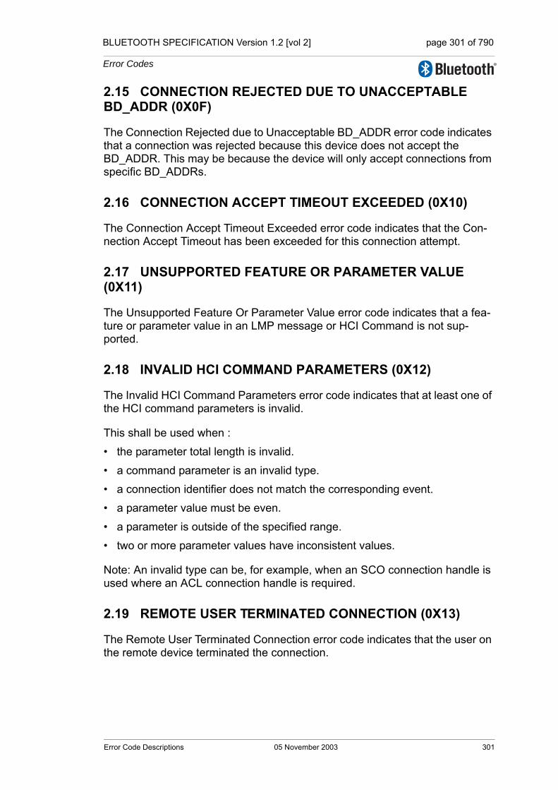
BLUETOOTH SPECIFICATION Version 1.2 [vol 2] page 301 of 790
Error Codes
2.15 CONNECTION REJECTED DUE TO UNACCEPTABLE BD_ADDR (0X0F)
The Connection Rejected due to Unacceptable BD_ADDR error code indicates that a connection was rejected because this device does not accept the BD_ADDR. This may be because the device will only accept connections from specific BD_ADDRs.
2.16 CONNECTION ACCEPT TIMEOUT EXCEEDED (0X10)
The Connection Accept Timeout Exceeded error code indicates that the Con-nection Accept Timeout has been exceeded for this connection attempt.
2.17 UNSUPPORTED FEATURE OR PARAMETER VALUE (0X11)
The Unsupported Feature Or Parameter Value error code indicates that a fea-ture or parameter value in an LMP message or HCI Command is not sup-ported.
2.18 INVALID HCI COMMAND PARAMETERS (0X12)
The Invalid HCI Command Parameters error code indicates that at least one of the HCI command parameters is invalid.
This shall be used when :
• the parameter total length is invalid.
• a command parameter is an invalid type.
• a connection identifier does not match the corresponding event.
• a parameter value must be even.
• a parameter is outside of the specified range.
• two or more parameter values have inconsistent values.
Note: An invalid type can be, for example, when an SCO connection handle is used where an ACL connection handle is required.
2.19 REMOTE USER TERMINATED CONNECTION (0X13)
The Remote User Terminated Connection error code indicates that the user on the remote device terminated the connection.
Error Code Descriptions 05 November 2003 301

BLUETOOTH SPECIFICATION Version 1.2 [vol 2] page 302 of 790
Error Codes
2.20 REMOTE DEVICE TERMINATED CONNECTION DUE TO LOW RESOURCES (0X14)
The Remote Device Terminated Connection due to Low Resources error code indicates that the remote device terminated the connection because of low resources.
2.21 REMOTE DEVICE TERMINATED CONNECTION DUE TO POWER OFF (0X15)
The Remote Device Terminated Connection due to Power Off error code indi-cates that the remote device terminated the connection because the device is about to power off.
2.22 CONNECTION TERMINATED BY LOCAL HOST (0X16)
The Connection Terminated By Local Host error code indicates that the local device terminated the connection.
2.23 REPEATED ATTEMPTS (0X17)
The Repeated Attempts error code indicates that the controller is disallowing an authentication or pairing procedure because too little time has elapsed since the last authentication or pairing attempt failed.
2.24 PAIRING NOT ALLOWED (0X18)
The Pairing Not Allowed error code indicates that the device does not allow pairing. For example, when a device only allows pairing during a certain time window after some user input allows pairing.
2.25 UNKNOWN LMP PDU (0X19)
The Unknown LMP PDU error code indicates that the controller has received an unknown LMP opcode.
2.26 UNSUPPORTED REMOTE FEATURE (0X1A)
The Unsupported Remote Feature error code indicates that the remote device does not support the feature associated with the issued command or LMP PDU.
2.27 SCO OFFSET REJECTED (0X1B)
The SCO Offset Rejected error code indicates that the offset requested in the LMP_SCO_link_req message has been rejected.
302 05 November 2003 Error Code Descriptions

BLUETOOTH SPECIFICATION Version 1.2 [vol 2] page 303 of 790
Error Codes
2.28 SCO INTERVAL REJECTED (0X1C)
The SCO Interval Rejected error code indicates that the interval requested in the LMP_SCO_link_req message has been rejected.
2.29 SCO AIR MODE REJECTED (0X1D)
The SCO Air Mode Rejected error code indicates that the air mode requested in the LMP_SCO_link_req message has been rejected.
2.30 INVALID LMP PARAMETERS (0X1E)
The Invalid LMP Parameters error code indicates that some LMP message parameters were invalid. This shall be used when :
• the PDU length is invalid.
• a parameter value must be even.
• a parameter is outside of the specified range.
• two or more parameters have inconsistent values.
2.31 UNSPECIFIED ERROR (0X1F)
The Unspecified Error error code indicates that no other error code specified is appropriate to use.
2.32 UNSUPPORTED LMP PARAMETER VALUE (0X20)
The Unsupported LMP Parameter Value error code indicates that an LMP mes-sage contains at least one parameter value that is not supported by the control-ler at this time. This is normally used after a long negotiation procedure, for example during an LMP_hold_req, LMP_sniff_req and LMP_encryption_key_size_req message exchanges.
2.33 ROLE CHANGE NOT ALLOWED (0X21)
The Role Change Not Allowed error code indicates that a controller will not allow a role change at this time.
2.34 LMP RESPONSE TIMEOUT (0X22)
The LMP Response Timeout error code indicates that an LMP transaction failed to respond within the LMP response timeout.
Error Code Descriptions 05 November 2003 303

BLUETOOTH SPECIFICATION Version 1.2 [vol 2] page 304 of 790
Error Codes
2.35 LMP ERROR TRANSACTION COLLISION (0X23)
The LMP Error Transaction Collision error code indicates that an LMP transac-tion has collided with the same transaction that is already in progress.
2.36 LMP PDU NOT ALLOWED (0X24)
The LMP PDU Not Allowed error code indicates that a controller sent an LMP message with an opcode that was not allowed.
2.37 ENCRYPTION MODE NOT ACCEPTABLE (0X25)
The Encryption Mode Not Acceptable error code indicates that the requested encryption mode is not acceptable at this time.
2.38 LINK KEY CAN NOT BE CHANGED (0X26)
The Link Key Can Not be Changed error code indicates that a link key can not be changed because a fixed unit key is being used.
2.39 REQUESTED QoS NOT SUPPORTED (0X27)
The Requested QoS Not Supported error code indicates that the requested Quality of Service is not supported.
2.40 INSTANT PASSED (0X28)
The Instant Passed error code indicates that an LMP PDU that includes an instant can not be performed because the instant when this would have occurred has passed.
2.41 PAIRING WITH UNIT KEY NOT SUPPORTED (0X29)
The Pairing With Unit Key Not Supported error code indicates that it was not possible to pair as a unit key was requested and it is not supported.
2.42 DIFFERENT TRANSACTION COLLISION (0X2A)
The Different Transaction Collision error code indicates that an LMP transac-tion was started that collides with an ongoing transaction.
2.43 QoS UNACCEPTABLE PARAMETER (0X2C)
The QoS Unacceptable Parameter error code indicates that the specified qual-ity of service parameters could not be accepted at this time, but other parame-ters may be acceptable.
304 05 November 2003 Error Code Descriptions
BLUETOOTH SPECIFICATION Version 1.2 [vol 2] page 305 of 790
Error Codes
2.44 QoS REJECTED (0X2D)
The QoS Rejected error code indicates that the specified quality of service parameters can not be accepted and QoS negotiation should be terminated.
2.45 CHANNEL CLASSIFICATION NOT SUPPORTED (0X2E)
The Channel Classification Not Supported error code indicates that the control-ler can not perform channel classification because it is not supported.
2.46 INSUFFICIENT SECURITY (0X2F)
The Insufficient Security error code indicates that the HCI command or LMP message sent is only possible on an encrypted link.
2.47 PARAMETER OUT OF MANDATORY RANGE (0X30)
The Parameter Out Of Mandatory Range error code indicates that a parameter value requested is outside the mandatory range of parameters for the given HCI command or LMP message.
2.48 ROLE SWITCH PENDING (0X32)
The Role Switch Pending error code indicates that a Role Switch is pending. This can be used when an HCI command or LMP message can not be accepted because of a pending role switch. This can also be used to notify a peer device about a pending role switch.
2.49 RESERVED SLOT VIOLATION (0X34)
The Reserved Slot Violation error code indicates that the current Synchronous negotiation was terminated with the negotiation state set to Reserved Slot Vio-lation.
2.50 ROLE SWITCH FAILED (0X35)
The Role Switch Failed error code indicates that a role switch was attempted but it failed and the original piconet structure is restored. The switch may have failed because the TDD switch or piconet switch failed.
Error Code Descriptions 05 November 2003 305

BLUETOOTH SPECIFICATION Version 1.2 [vol 2] page 306 of 790
Error Codes
306 05 November 2003 Error Code Descriptions
Core System Package [Controller volume]
Part EHOST CONTROLLER INTERFACEFUNCTIONAL SPECIFICATION
This document describes the functional specification for the Host Controller Interface (HCI). The HCI provides a command interface to the baseband controller and link manager, and access to configuration parameters. This interface provides a uniform method of accessing the Bluetooth baseband capabilities.

BLUETOOTH SPECIFICATION Version 1.2 [vol 2] page 308 of 790
Host Controller Interface Functional Specification
308 05 November 2003
BLUETOOTH SPECIFICATION Version 1.2 [vol 2] page 309 of 790
Host Controller Interface Functional Specification
CONTENTS
1 Introduction ......................................................................................3171.1 Lower Layers of the Bluetooth Software Stack ........................317
2 Overview of Host Controller Transport Layer................................3193 Overview of Commands and Events ..............................................321
3.1 Generic Events.........................................................................3223.2 Device Setup............................................................................3223.3 Controller Flow Control ............................................................3233.4 Controller Information...............................................................3233.5 Controller Configuration ...........................................................3243.6 Device Discovery .....................................................................3253.7 Connection Setup ....................................................................3273.8 Remote Information..................................................................3293.9 Synchronous Connections .......................................................3303.10 Connection State......................................................................3313.11 Piconet Structure......................................................................3323.12 Quality of Service.....................................................................3333.13 Physical Links ..........................................................................3343.14 Host Flow Control.....................................................................3353.15 Link Information .......................................................................3363.16 Authentication and Encryption .................................................3373.17 Testing......................................................................................3393.18 Alphabetical List of Commands and Events ............................340
4 HCI Flow Control ..............................................................................3454.1 Host to Controller Data Flow Control .......................................3454.2 Controller to Host Data Flow Control .......................................3464.3 Disconnection Behaviour .........................................................3474.4 Command Flow Control ...........................................................3474.5 Command Error Handling ........................................................348
5 HCI Data Formats .............................................................................3495.1 Introduction ..............................................................................3495.2 Data and Parameter Formats...................................................3495.3 Connection Handles.................................................................3505.4 Exchange of HCI-Specific Information .....................................351
5.4.1 HCI Command Packet.................................................3515.4.2 HCI ACL Data Packets................................................3535.4.3 HCI Synchronous Data Packets..................................3555.4.4 HCI Event Packet ........................................................356
05 November 2003 309

BLUETOOTH SPECIFICATION Version 1.2 [vol 2] page 310 of 790
Host Controller Interface Functional Specification
6 HCI Configuration Parameters........................................................3576.1 Scan Enable ............................................................................3576.2 Inquiry Scan Interval ................................................................3576.3 Inquiry Scan Window ...............................................................3586.4 Inquiry Scan Type ....................................................................3586.5 Inquiry Mode ............................................................................3586.6 Page Timeout...........................................................................3596.7 Connection Accept Timeout.....................................................3596.8 Page Scan Interval ..................................................................3606.9 Page Scan Window .................................................................3606.10 Page Scan Period Mode..........................................................3606.11 Page Scan Type ......................................................................3616.12 Voice Setting............................................................................3616.13 PIN Type ..................................................................................3626.14 Link Key ...................................................................................3626.15 Authentication Enable..............................................................3626.16 Encryption Mode......................................................................3636.17 Failed Contact Counter ............................................................3646.18 Hold Mode Activity ...................................................................3646.19 Link Policy Settings..................................................................3656.20 Flush Timeout ..........................................................................3666.21 Num Broadcast Retransmissions ............................................3666.22 Link Supervision Timeout.........................................................3676.23 Synchronous Flow Control Enable ..........................................3676.24 Local Name..............................................................................3686.25 Class Of Device .......................................................................3686.26 Supported Commands.............................................................369
7 HCI Commands and Events ............................................................3737.1 Link Control Commands ..........................................................373
7.1.1 Inquiry Command........................................................3737.1.2 Inquiry Cancel Command............................................3757.1.3 Periodic Inquiry Mode Command................................3767.1.4 Exit Periodic Inquiry Mode Command.........................3797.1.5 Create Connection Command.....................................3807.1.6 Disconnect Command.................................................3837.1.7 Create Connection Cancel Command ........................3847.1.8 Accept Connection Request Command......................3867.1.9 Reject Connection Request Command.......................3887.1.10 Link Key Request Reply Command ............................3897.1.11 Link Key Request Negative Reply Command.............3917.1.12 PIN Code Request Reply Command ..........................392
310 05 November 2003

BLUETOOTH SPECIFICATION Version 1.2 [vol 2] page 311 of 790
Host Controller Interface Functional Specification
7.1.13 PIN Code Request Negative Reply Command ...........3947.1.14 Change Connection Packet Type Command ..............3957.1.15 Authentication Requested Command..........................3987.1.16 Set Connection Encryption Command ........................3997.1.17 Change Connection Link Key Command ....................4007.1.18 Master Link Key Command.........................................4017.1.19 Remote Name Request Command .............................4027.1.20 Remote Name Request Cancel Command.................4047.1.21 Read Remote Supported Features Command............4057.1.22 Read Remote Extended Features Command ............4067.1.23 Read Remote Version Information Command.............4077.1.24 Read Clock Offset Command......................................4087.1.25 Read LMP Handle Command ....................................4097.1.26 Setup Synchronous Connection Command ...............4117.1.27 Accept Synchronous Connection Request Command 4157.1.28 Reject Synchronous Connection Request Command.419
7.2 Link Policy Commands.............................................................4207.2.1 Hold Mode Command .................................................4207.2.2 Sniff Mode Command..................................................4227.2.3 Exit Sniff Mode Command...........................................4257.2.4 Park State Command ..................................................4267.2.5 Exit Park State Command ...........................................4287.2.6 QoS Setup Command .................................................4297.2.7 Role Discovery Command...........................................4317.2.8 Switch Role Command................................................4327.2.9 Read Link Policy Settings Command ..........................4337.2.10 Write Link Policy Settings Command ..........................4347.2.11 Read Default Link Policy Settings Command .............4367.2.12 Write Default Link Policy Settings Command .............4377.2.13 Flow Specification Command .....................................438
05 November 2003 311
BLUETOOTH SPECIFICATION Version 1.2 [vol 2] page 312 of 790
Host Controller Interface Functional Specification
7.3 Controller & Baseband Commands .........................................4407.3.1 Set Event Mask Command .........................................4407.3.2 Reset Command .........................................................4427.3.3 Set Event Filter Command..........................................4437.3.4 Flush Command..........................................................4487.3.5 Read PIN Type Command ..........................................4507.3.6 Write PIN Type Command ..........................................4517.3.7 Create New Unit Key Command.................................4527.3.8 Read Stored Link Key Command................................4537.3.9 Write Stored Link Key Command................................4547.3.10 Delete Stored Link Key Command..............................4567.3.11 Write Local Name Command ......................................4577.3.12 Read Local Name Command......................................4587.3.13 Read Connection Accept Timeout Command.............4597.3.14 Write Connection Accept Timeout Command .............4607.3.15 Read Page Timeout Command...................................4617.3.16 Write Page Timeout Command...................................4627.3.17 Read Scan Enable Command.....................................4637.3.18 Write Scan Enable Command.....................................4647.3.19 Read Page Scan Activity Command...........................4657.3.20 Write Page Scan Activity Command ...........................4677.3.21 Read Inquiry Scan Activity Command.........................4687.3.22 Write Inquiry Scan Activity Command.........................4697.3.23 Read Authentication Enable Command......................4707.3.24 Write Authentication Enable Command ......................4717.3.25 Read Encryption Mode Command..............................4727.3.26 Write Encryption Mode Command ..............................4737.3.27 Read Class of Device Command................................4747.3.28 Write Class of Device Command ................................4757.3.29 Read Voice Setting Command....................................4767.3.30 Write Voice Setting Command ....................................4777.3.31 Read Automatic Flush Timeout Command .................4787.3.32 Write Automatic Flush Timeout Command..................4797.3.33 Read Num Broadcast Retransmissions Command.....4807.3.34 Write Num Broadcast Retransmissions Command.....4817.3.35 Read Hold Mode Activity Command ...........................4827.3.36 Write Hold Mode Activity Command ...........................4837.3.37 Read Transmit Power Level Command ......................484
312 05 November 2003

BLUETOOTH SPECIFICATION Version 1.2 [vol 2] page 313 of 790
Host Controller Interface Functional Specification
7.3.38 Read Synchronous Flow Control Enable Command...4867.3.39 Write Synchronous Flow Control Enable Command ...4877.3.40 Set Controller To Host Flow Control Command ..........4887.3.41 Host Buffer Size Command.........................................4897.3.42 Host Number Of Completed Packets Command.........4917.3.43 Read Link Supervision Timeout Command.................4937.3.44 Write Link Supervision Timeout Command .................4947.3.45 Read Number Of Supported IAC Command...............4967.3.46 Read Current IAC LAP Command ..............................4977.3.47 Write Current IAC LAP Command...............................4987.3.48 Read Page Scan Period Mode Command ..................5007.3.49 Write Page Scan Period Mode Command ..................5017.3.50 Set AFH Host Channel Classification Command .......5027.3.51 Read Inquiry Scan Type Command ...........................5037.3.52 Write Inquiry Scan Type Command ............................5047.3.53 Read Inquiry Mode Command ...................................5057.3.54 Write Inquiry Mode Command ....................................5067.3.55 Read Page Scan Type Command ..............................5077.3.56 Write Page Scan Type Command ..............................5087.3.57 Read AFH Channel Assessment Mode Command ....5097.3.58 Write AFH Channel Assessment Mode Command ....510
7.4 Informational Parameters.........................................................5127.4.1 Read Local Version Information Command.................5127.4.2 Read Local Supported Commands Command............5147.4.3 Read Local Supported Features Command................5157.4.4 Read Local Extended Features Command ................5167.4.5 Read Buffer Size Command........................................5187.4.6 Read BD_ADDR Command........................................520
7.5 Status Parameters....................................................................5217.5.1 Read Failed Contact Counter Command ....................5217.5.2 Reset Failed Contact Counter Command ...................5237.5.3 Read Link Quality Command ......................................5247.5.4 Read RSSI Command.................................................5257.5.5 Read AFH Channel Map Command ...........................5277.5.6 Read Clock Command ...............................................529
7.6 Testing Commands ..................................................................5317.6.1 Read Loopback Mode Command ...............................5317.6.2 Write Loopback Mode Command................................5327.6.3 Enable Device Under Test Mode Command ...............535
05 November 2003 313
BLUETOOTH SPECIFICATION Version 1.2 [vol 2] page 314 of 790
Host Controller Interface Functional Specification
7.7 Events......................................................................................5377.7.1 Inquiry Complete Event...............................................5377.7.2 Inquiry Result Event ....................................................5387.7.3 Connection Complete Event .......................................5407.7.4 Connection Request Event .........................................5417.7.5 Disconnection Complete Event ...................................5437.7.6 Authentication Complete Event...................................5447.7.7 Remote Name Request Complete Event ....................5457.7.8 Encryption Change Event ...........................................5467.7.9 Change Connection Link Key Complete Event ...........5477.7.10 Master Link Key Complete Event................................5487.7.11 Read Remote Supported Features Complete Event...5497.7.12 Read Remote Version Information Complete Event ...5507.7.13 QoS Setup Complete Event ........................................5517.7.14 Command Complete Event .........................................5537.7.15 Command Status Event ..............................................5547.7.16 Hardware Error Event .................................................5557.7.17 Flush Occurred Event .................................................5557.7.18 Role Change Event .....................................................5567.7.19 Number Of Completed Packets Event ........................5577.7.20 Mode Change Event ...................................................5587.7.21 Return Link Keys Event...............................................5607.7.22 PIN Code Request Event ............................................5617.7.23 Link Key Request Event..............................................5627.7.24 Link Key Notification Event .........................................5637.7.25 Loopback Command Event.........................................5647.7.26 Data Buffer Overflow Event.........................................5647.7.27 Max Slots Change Event.............................................5657.7.28 Read Clock Offset Complete Event ............................5667.7.29 Connection Packet Type Changed Event ...................5677.7.30 QoS Violation Event ....................................................5697.7.31 Page Scan Repetition Mode Change Event................5707.7.32 Flow Specification Complete Event.............................5717.7.33 Inquiry Result with RSSI Event ..................................5737.7.34 Read Remote Extended Features Complete Event ....5757.7.35 Synchronous Connection Complete Event .................5767.7.36 Synchronous Connection Changed event...................578
314 05 November 2003
BLUETOOTH SPECIFICATION Version 1.2 [vol 2] page 315 of 790
Host Controller Interface Functional Specification
8 List of Figures...................................................................................5819 List of Tables ....................................................................................583
Appendix A: Deprecated Commands, Events and Configuration Parameters ...........585
Contents: ...........................................................................................585Page Scan Mode ....................................................................586Read Page Scan Mode Command .........................................587Write Page Scan Mode Command ..........................................588Read Country Code Command ...............................................589Add SCO Connection Command ............................................590Page Scan Mode Change Event .............................................592
05 November 2003 315

BLUETOOTH SPECIFICATION Version 1.2 [vol 2] page 316 of 790
Host Controller Interface Functional Specification
316 05 November 2003

BLUETOOTH SPECIFICATION Version 1.2 [vol 2] page 317 of 790
Host Controller Interface Functional Specification
1 INTRODUCTION
This document describes the functional specifications for the Host Controller Interface (HCI). The HCI provides a uniform interface method of accessing the Bluetooth controller capabilities. The next two sections provide a brief overview of the lower layers of the Bluetooth software stack and of the Bluetooth hard-ware. Section 2, provides an overview of the Lower HCI Device Driver Interface on the host device. Section 4, describes the flow control used between the Host and the Controller. Section 7, describes each of the HCI Commands in details, identifies parameters for each of the commands, and lists events asso-ciated with each command.
1.1 LOWER LAYERS OF THE BLUETOOTH SOFTWARE STACK
Figure 1.1: Overview of the Lower Software Layers
Figure 1.1, provides an overview of the lower software layers. The HCI firm-ware implements the HCI Commands for the Bluetooth hardware by accessing baseband commands link manager commands, hardware status registers, control registers, and event registers.
Several layers may exist between the HCI driver on the host system and the HCI firmware in the Bluetooth hardware. These intermediate layers, the Host
Physical Bus
Hardware
Bluetooth Host
Bluetooth Controller
Other Higher Layer Driver
HCI Driver
Physical Bus (USB,
PC Card,Other) Driver
Physical Bus (USB,
PC Card, Other) Firmware
HCI Firmware
Baseband Controller
Software
Firmware
Harware
Link Manager
Firmware
Hardware
Introduction 05 November 2003 317
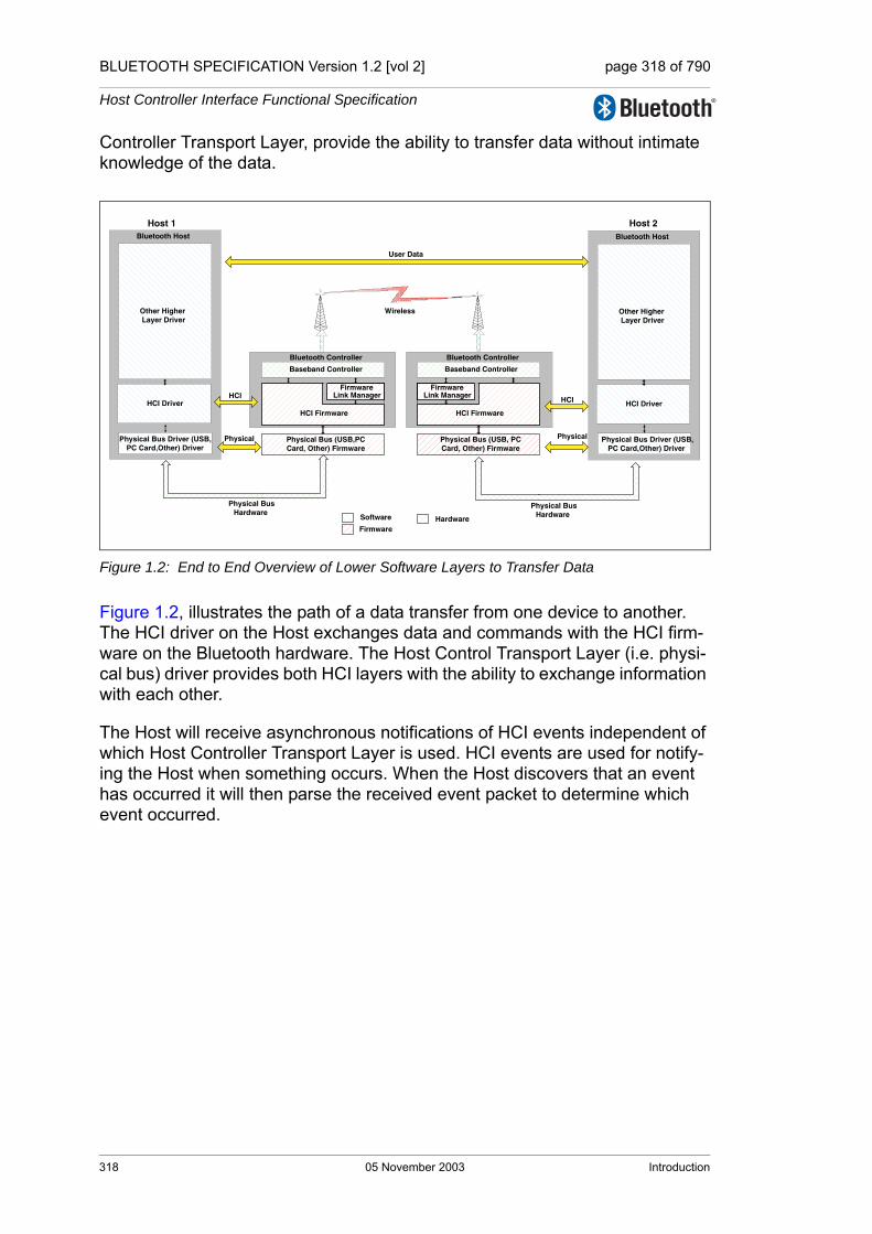
BLUETOOTH SPECIFICATION Version 1.2 [vol 2] page 318 of 790
Host Controller Interface Functional Specification
Controller Transport Layer, provide the ability to transfer data without intimate knowledge of the data.
Figure 1.2: End to End Overview of Lower Software Layers to Transfer Data
Figure 1.2, illustrates the path of a data transfer from one device to another. The HCI driver on the Host exchanges data and commands with the HCI firm-ware on the Bluetooth hardware. The Host Control Transport Layer (i.e. physi-cal bus) driver provides both HCI layers with the ability to exchange information with each other.
The Host will receive asynchronous notifications of HCI events independent of which Host Controller Transport Layer is used. HCI events are used for notify-ing the Host when something occurs. When the Host discovers that an event has occurred it will then parse the received event packet to determine which event occurred.
Physical Bus (USB,PCCard, Other) Firmware
Bluetooth Controller
HCI Firmware
Baseband Controller
Link ManagerFirmware
Physical BusHardware
HCI
Physical Bus (USB, PCCard, Other) Firmware
Bluetooth Controller
HCI Firmware
Baseband Controller
Link ManagerFirmware
HCI
Software
FirmwareHardware
Host 1 Host 2
Physical BusHardware
Bluetooth Host
Other Higher Layer Driver
HCI Driver
Physical Bus Driver (USB,PC Card,Other) Driver
Bluetooth Host
Other Higher Layer Driver
HCI Driver
Physical Bus Driver (USB,PC Card,Other) Driver
Wireless
User Data
Physical Physical
318 05 November 2003 Introduction
BLUETOOTH SPECIFICATION Version 1.2 [vol 2] page 319 of 790
Host Controller Interface Functional Specification
2 OVERVIEW OF HOST CONTROLLER TRANSPORT LAYER
The host driver stack has a transport layer between the Host Controller driver and the Host.
The main goal of this transport layer is transparency. The Host Controller driver (which interaces to the Controller) should be independent of the underlying transport technology. Nor should the transport require any visibility into the data that the Host Controller driver passes to the Controller. This allows the inter-face (HCI) or the Controller to be upgraded without affecting the transport layer.
The specified Host Controller Transport Layers are described in a separate vol-ume. (See specification volume 4)
Overview of Host Controller Transport Layer 05 November 2003 319

BLUETOOTH SPECIFICATION Version 1.2 [vol 2] page 320 of 790
Host Controller Interface Functional Specification
320 05 November 2003 Overview of Host Controller Transport Layer

BLUETOOTH SPECIFICATION Version 1.2 [vol 2] page 321 of 790
Host Controller Interface Functional Specification
3 OVERVIEW OF COMMANDS AND EVENTS
The commands and events are sent between the Host and the Controller. These are grouped into logical groups by function.
The version information in this section denotes the version number of the spec-ification that this command or event was first specified
Generic EventsThe generic events can occur due to multiple com-mands, or events that can occur at any time.
Device SetupThe device setup commands are used to place the Con-troller into a known state.
Controller Flow ControlThe controller flow control commands and events are used to control data flow from the Host to the controller.
Controller InformationThe controller information commands allow the Host to discover local information about the device.
Controller ConfigurationThe controller configuration commands and events allow the global configuration parameters to be configured.
Device DiscoveryThe device discovery commands and events allow a device to discover other devices in the surrounding area.
Connection SetupThe connection setup commands and events allow a device to make a connection to another device.
Remote InformationThe remote information commands and events allow information about a remote device's configuration to be discovered.
Synchronous ConnectionsThe synchronous connection commands and events allow synchronous connections to be created
Connection StateThe connection state commands and events allow the configuration of a link, especially for low power operation.
Piconet StructureThe piconet structure commands and events allow the discovery and reconfiguration of piconet.
Quality of ServiceThe quality of service commands and events allow qual-ity of service parameters to be specified.
Physical LinksThe physical link commands and events allow the con-figuration of a physical link.
Host Flow ControlThe Host flow control commands and events allow flow control to be used towards the Host.
Link InformationThe link information commands and events allow infor-mation about a link to be read.
Authentication and EncryptionThe authentication and encryption commands and events allow authentication of a remote device and then encryption of the link.
TestingThe testing commands and events allow a device to be placed into test mode.
Table 3.1: Overview of commands and events
Overview of Commands and Events 05 November 2003 321

BLUETOOTH SPECIFICATION Version 1.2 [vol 2] page 322 of 790
Host Controller Interface Functional Specification
3.1 GENERIC EVENTS
The generic events occur due to multiple commands, or events that can occur at any time.
3.2 DEVICE SETUP
The device setup group of commands are used to place the Controller into a known state.
Name Vers. Summary description
Command Complete Event 1.1The Command Complete event is used by the Con-troller to pass the return status of a command and the other event parameters for each HCI Command.
Command Status Event 1.1
The Command Status event is used to indicate that the command described by the Command_Opcode parameter has been received and the Controller is currently performing the task for this command.
Hardware Error Event 1.1 The Hardware Error event is used to indicate some type of hardware failure for the Controller.
Table 3.2: Generic events
Name Vers. Summary description
Reset Command 1.1 The Reset command will reset the Controller, Link Manager, and the Bluetooth radio.
Device setup
322 05 November 2003 Overview of Commands and Events

BLUETOOTH SPECIFICATION Version 1.2 [vol 2] page 323 of 790
Host Controller Interface Functional Specification
3.3 CONTROLLER FLOW CONTROL
The controller flow control group of commands and events are used to control data flow from the Host to the Controller.
3.4 CONTROLLER INFORMATION
The controller information group of commands allows the Host to discover local information about the device.
Name Vers. Summary description
Read Buffer Size Com-mand 1.1
The Read_Buffer_Size command returns the size of the HCI buffers. These buffers are used by the Con-troller to buffer data that is to be transmitted.
Number Of Completed Packets Event 1.1
The Number Of Completed Packets event is used by the Controller to indicate to the Host how many HCI Data Packets have been completed for each Connec-tion Handle since the previous Number Of Completed Packets event was sent.
Table 3.3: Controller flow control
Name Vers. Summary description
Read Local Version Infor-mation Command 1.1
The Read Local Version Information command will read the version information for the local Bluetooth device.
Read Local Supported Commands Command 1.2
The Read Local Supported Commands command requests a list of the supported HCI commands for the local device.
Read Local Supported Features Command 1.1
The Read Local Supported Features command requests a list of the supported features for the local device.
Read Local Extended Fea-tures Command 1.2
The Read Local Extended Features command requests a list of the supported extended features for the local device
Read BD_ADDR Com-mand 1.1 The Read BD_ADDR command will read the value
for the BD_ADDR parameter.
Table 3.4: Controller information
Overview of Commands and Events 05 November 2003 323

BLUETOOTH SPECIFICATION Version 1.2 [vol 2] page 324 of 790
Host Controller Interface Functional Specification
3.5 CONTROLLER CONFIGURATION
The controller configuration group of commands and events allows the global configuration parameters to be configured.
Name Vers. Summary description
Read Local Name Com-mand 1.1
The Read Local Name command provides the ability to read the stored user-friendly name for the Blue-tooth device.
Write Local Name Com-mand 1.1
The Write Local Name command provides the ability to modify the user-friendly name for the Bluetooth device.
Read Class of Device Command 1.1
The Read Class of Device command will read the value for the Class of Device configuration parame-ter, which is used to indicate its capabilities to other devices.
Write Class of Device Command 1.1
The Write Class of Device command will write the value for the Class_of_Device configuration parame-ter, which is used to indicate its capabilities to other devices.
Read Number Of Sup-ported IAC Command 1.1
The Read Number of Supported IAC command will read the value for the number of Inquiry Access Codes (IAC) that the local Bluetooth device can simultaneously listen for during an Inquiry Scan.
Read Current IAC LAP Command 1.1
The Read Current IAC LAP command will read the LAP(s) used to create the Inquiry Access Codes (IAC) that the local Bluetooth device is simulta-neously scanning for during Inquiry Scans.
Write Current IAC LAP Command 1.1
The Write Current IAC LAP command will write the LAP(s) used to create the Inquiry Access Codes (IAC) that the local Bluetooth device is simulta-neously scanning for during Inquiry Scans.
Read Scan Enable Com-mand 1.1
The Read Scan Enable command will read the value for the Scan Enable configuration parameter, which controls whether or not the Bluetooth device will peri-odically scan for page attempts and/or inquiry requests from other Bluetooth devices.
Write Scan Enable Com-mand 1.1
The Write Scan Enable command will write the value for the Scan Enable configuration parameter, which controls whether or not the Bluetooth device will peri-odically scan for page attempts and/or inquiry requests from other Bluetooth devices.
Table 3.5: Controller configuration
324 05 November 2003 Overview of Commands and Events

BLUETOOTH SPECIFICATION Version 1.2 [vol 2] page 325 of 790
Host Controller Interface Functional Specification
3.6 DEVICE DISCOVERY
The device discovery group of commands and events allow a device to discov-ery other devices in the surrounding area.
Name Vers. Summary description
Inquiry Command 1.1The Inquiry command will cause the Bluetooth device to enter Inquiry Mode. Inquiry Mode is used to discov-ery other nearby Bluetooth devices.
Inquiry Result Event 1.1The Inquiry Result event indicates that a Bluetooth device or multiple Bluetooth devices have responded so far during the current Inquiry process.
Inquiry Result with RSSI Event 1.2
The Inquiry Result with RSSI event indicates that a Bluetooth device or multiple Bluetooth devices have responded so far during the current Inquiry process.
Inquiry Cancel Command 1.1The Inquiry Cancel command will cause the Blue-tooth device to stop the current Inquiry if the Blue-tooth device is in Inquiry Mode.
Inquiry Complete Event 1.1 The Inquiry Complete event indicates that the Inquiry is finished.
Periodic Inquiry Mode Command 1.1
The Periodic Inquiry Mode command is used to con-figure the Bluetooth device to perform an automatic Inquiry based on a specified period range.
Exit Periodic Inquiry Mode Command 1.1
The Exit Periodic Inquiry Mode command is used to end the Periodic Inquiry mode when the local device is in Periodic Inquiry Mode.
Read Inquiry Scan Activity Command 1.1
The Read Inquiry Scan Activity command will read the value for Inquiry Scan Interval and Inquiry Scan Window configuration parameters. Inquiry Scan Inter-val defines the amount of time between consecutive inquiry scans. Inquiry Scan Window defines the amount of time for the duration of the inquiry scan.
Write Inquiry Scan Activity Command 1.1
The Write Inquiry Scan Activity command will write the value for Inquiry Scan Interval and Inquiry Scan Window configuration parameters. Inquiry Scan Inter-val defines the amount of time between consecutive inquiry scans. Inquiry Scan Window defines the amount of time for the duration of the inquiry scan.
Read Inquiry Scan Type Command 1.2
The Read Inquiry Scan Type command is used to read the Inquiry Scan Type configuration parameter of the local Bluetooth device. The Inquiry Scan Type configuration parameter can set the inquiry scan to either normal or interlaced scan.
Table 3.6: Device discovery
Overview of Commands and Events 05 November 2003 325

BLUETOOTH SPECIFICATION Version 1.2 [vol 2] page 326 of 790
Host Controller Interface Functional Specification
Write Inquiry Scan Type Command 1.2
The Write Inquiry Scan Type command is used to write the Inquiry Scan Type configuration parameter of the local Bluetooth device. The Inquiry Scan Type configuration parameter can set the inquiry scan to either normal or interlaced scan.
Read Inquiry Mode Com-mand 1.2
The Read Inquiry Mode command is used to read the Inquiry Mode configuration parameter of the local Bluetooth device.
Write Inquiry Mode Com-mand 1.2
The Write Inquiry Mode command is used to write the Inquiry Mode configuration parameter of the local Bluetooth device.
Name Vers. Summary description
Table 3.6: Device discovery
326 05 November 2003 Overview of Commands and Events

BLUETOOTH SPECIFICATION Version 1.2 [vol 2] page 327 of 790
Host Controller Interface Functional Specification
3.7 CONNECTION SETUP
The connection setup group of commands and events are used to allow a device to make a connection to another device.
Name Vers. Summary description
Create Connection Com-mand 1.1
The Create Connection command will cause the link manager to create an ACL connection to the Blue-tooth device with the BD_ADDR specified by the command parameters.
Connection Request Event 1.1The Connection Request event is used to indicate that a new incoming connection is trying to be estab-lished.
Accept Connection Request Command 1.1 The Accept Connection Request command is used to
accept a new incoming connection request.
Reject Connection Request Command 1.1 The Reject Connection Request command is used to
decline a new incoming connection request.
Create Connection Cancel Command
1.2 The Create Connection Cancel Command is used to cancel an ongoing Create Connection.
Connection Complete Event 1.1
The Connection Complete event indicates to both of the Hosts forming the connection that a new connec-tion has been established.
Disconnect Command 1.1 The Disconnect command is used to terminate an existing connection.
Disconnection Complete Event 1.1 The Disconnection Complete event occurs when a
connection has been terminated.
Read Page Timeout Com-mand 1.1
The Read Page Timeout command will read the value for the Page Reply Timeout configuration parameter, which determines the time the Bluetooth controller will wait for the remote device to respond to a connection request before the local device returns a connection failure.
Write Page Timeout Com-mand 1.1
The Write Page Timeout command will write the value for the Page Reply Timeout configuration parameter, which allows the Bluetooth hardware to define the amount of time a connection request will wait for the remote device to respond before the local device returns a connection failure.
Read Page Scan Activity Command 1.1
The Read Page Scan Activity command will read the values for the Page Scan Interval and Page Scan Window configuration parameters. Page Scan Inter-val defines the amount of time between consecutive page scans. Page Scan Window defines the duration of the page scan.
Table 3.7: Connection setup
Overview of Commands and Events 05 November 2003 327
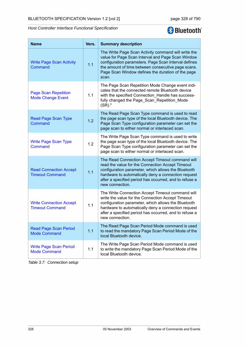
BLUETOOTH SPECIFICATION Version 1.2 [vol 2] page 328 of 790
Host Controller Interface Functional Specification
Write Page Scan Activity Command 1.1
The Write Page Scan Activity command will write the value for Page Scan Interval and Page Scan Window configuration parameters. Page Scan Interval defines the amount of time between consecutive page scans. Page Scan Window defines the duration of the page scan.
Page Scan Repetition Mode Change Event 1.1
The Page Scan Repetition Mode Change event indi-cates that the connected remote Bluetooth device with the specified Connection_Handle has success-fully changed the Page_Scan_Repetition_Mode (SR)."
Read Page Scan Type Command 1.2
The Read Page Scan Type command is used to read the page scan type of the local Bluetooth device. The Page Scan Type configuration parameter can set the page scan to either normal or interlaced scan.
Write Page Scan Type Command 1.2
The Write Page Scan Type command is used to write the page scan type of the local Bluetooth device. The Page Scan Type configuration parameter can set the page scan to either normal or interlaced scan.
Read Connection Accept Timeout Command 1.1
The Read Connection Accept Timeout command will read the value for the Connection Accept Timeout configuration parameter, which allows the Bluetooth hardware to automatically deny a connection request after a specified period has occurred, and to refuse a new connection.
Write Connection Accept Timeout Command 1.1
The Write Connection Accept Timeout command will write the value for the Connection Accept Timeout configuration parameter, which allows the Bluetooth hardware to automatically deny a connection request after a specified period has occurred, and to refuse a new connection.
Read Page Scan Period Mode Command 1.1
The Read Page Scan Period Mode command is used to read the mandatory Page Scan Period Mode of the local Bluetooth device.
Write Page Scan Period Mode Command 1.1
The Write Page Scan Period Mode command is used to write the mandatory Page Scan Period Mode of the local Bluetooth device.
Name Vers. Summary description
Table 3.7: Connection setup
328 05 November 2003 Overview of Commands and Events

BLUETOOTH SPECIFICATION Version 1.2 [vol 2] page 329 of 790
Host Controller Interface Functional Specification
3.8 REMOTE INFORMATION
The remote information group of commands and events allows information about a remote devices configuration to be discovered.
Name Vers. Summary description
Remote Name Request Command 1.1
The Remote Name Request command is used to obtain the user-friendly name of another Bluetooth device.
Remote Name Request Cancel Command
1.2 The Remote Name Request Cancel Command is used to cancel an ongoing Remote Name Request.
Remote Name Request Complete Event 1.1
The Remote Name Request Complete event is used to indicate a remote name request has been com-pleted.
Read Remote Supported Features Command 1.1
The Read Remote Supported Features command requests a list of the supported features of a remote device.
Read Remote Supported Features Complete Event 1.1
The Read Remote Supported Features Complete event is used to indicate the completion of the pro-cess of the Link Manager obtaining the supported features of the remote Bluetooth device specified by the Connection Handle event parameter.
Read Remote Extended Features Command 1.2
The Read Remote Extended Features command requests a list of the supported extended features of a remote device
Read Remote Extended Features Complete Event 1.2
The Read Remote Extended Features Complete Event is used to indicate the completion of the pro-cess of the Link Manager obtaining the supported Extended features of the remote Bluetooth device specified by the connection handle event parameter.
Read Remote Version Information Command 1.1
The Read Remote Version Information command will read the values for the version information for the remote Bluetooth device.
Read Remote Version Information Complete Event
1.1
The Read Remote Version Information Complete event is used to indicate the completion of the pro-cess of the Link Manager obtaining the version infor-mation of the remote Bluetooth device specified by the Connection Handle event parameter.
Table 3.8: Remote information
Overview of Commands and Events 05 November 2003 329

BLUETOOTH SPECIFICATION Version 1.2 [vol 2] page 330 of 790
Host Controller Interface Functional Specification
3.9 SYNCHRONOUS CONNECTIONS
The synchronous connections group of commands and events allows synchro-nous connections to be created.
Name Vers. Summary description
Setup Synchronous Con-nection Command 1.2
The Setup Synchronous Connection command adds a new or modifies an existing synchronous logical transport (SCO or eSCO) on a physical link depend-ing on the Connection Handle parameter specified.
Synchronous Connection Complete Event 1.2
The Synchronous Connection Complete event indi-cates to both the Hosts that a new Synchronous con-nection has been established.
Synchronous Connection Changed event 1.2
The Synchronous Connection Changed event indi-cates to the Host that an existing Synchronous con-nection has been reconfigured.
Accept Synchronous Con-nection Request Command 1.2
The Accept_Synchronous_Connection_Request command is used to accept an incoming request for a synchronous connection and to inform the local Link Manager about the acceptable parameter values for the synchronous connection.
Reject Synchronous Con-nection Request Command 1.2
The Reject_Synchronous_Connection_Request is used to decline an incoming request for a synchro-nous link.
Read Voice Setting Com-mand 1.1
The Read Voice Setting command will read the val-ues for the Voice Setting configuration parameter, which controls all the various settings for the voice connections.
Write Voice Setting Com-mand 1.1
The Write Voice Setting command will write the val-ues for the Voice Setting configuration parameter, which controls all the various settings for the voice connections.
Table 3.9: Synchronous connections
330 05 November 2003 Overview of Commands and Events

BLUETOOTH SPECIFICATION Version 1.2 [vol 2] page 331 of 790
Host Controller Interface Functional Specification
3.10 CONNECTION STATE
The connection state group of commands and events allows the configuration of a link, especially for low power operation.
Name Vers. Summary description
Mode Change Event 1.1 The Mode Change event is used to indicate that the current mode has changed.
Max Slots Change Event 1.1 The Max Slots Change event it used to indicate a change in the max slots by the LM.
Hold Mode Command 1.1 The Hold Mode command is used to initiate Hold Mode.
Sniff Mode Command 1.1The Sniff Mode command is used to alter the behav-ior of the LM and have the LM place the local or remote device into the sniff mode.
Exit Sniff Mode Command 1.1The Exit Sniff Mode command is used to end the sniff mode for a connection handle which is currently in sniff mode.
Park State Command 1.1The Park State command is used to alter the behav-ior of the LM and have the LM place the local or remote device into the park state.
Exit Park State Command 1.1 The Exit Park State command is used to switch the Bluetooth device from park state back to active mode.
Read Link Policy Settings Command 1.1
The Read Link Policy Settings command will read the Link Policy configuration parameter for the specified Connection Handle. The Link Policy settings allow the Host to specify which Link Modes the LM can use for the specified Connection Handle.
Write Link Policy Settings Command 1.1
The Write Link Policy Settings command will write the Link Policy configuration parameter for the specified Connection Handle. The Link Policy settings allow the Host to specify which Link Modes the LM can use for the specified Connection Handle.
Read Default Link Policy Settings Command 1.2
The Read Default Link Policy Settings command will read the Default Link Policy configuration parameter for all new connections.
Write Default Link Policy Settings Command 1.2
The Write Default Link Policy Settings command will write the Default Link Policy configuration parameter for all new connections.
Table 3.10: Connection state
Overview of Commands and Events 05 November 2003 331
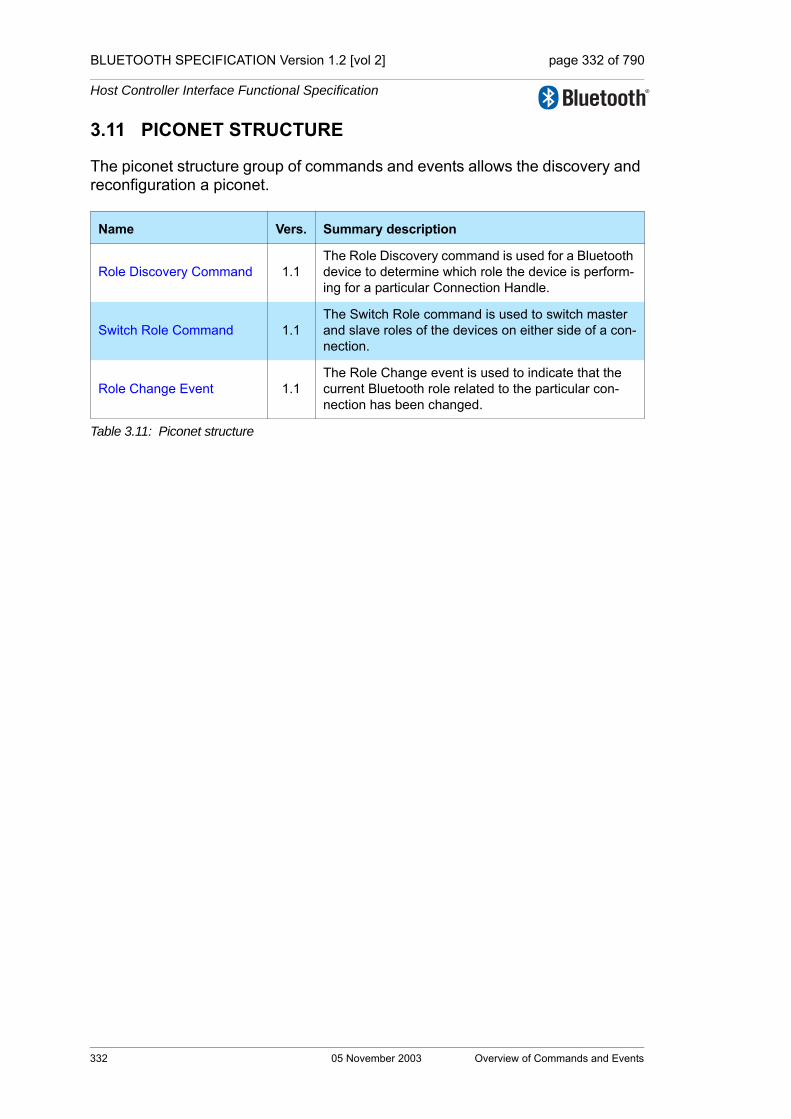
BLUETOOTH SPECIFICATION Version 1.2 [vol 2] page 332 of 790
Host Controller Interface Functional Specification
3.11 PICONET STRUCTURE
The piconet structure group of commands and events allows the discovery and reconfiguration a piconet.
Name Vers. Summary description
Role Discovery Command 1.1The Role Discovery command is used for a Bluetooth device to determine which role the device is perform-ing for a particular Connection Handle.
Switch Role Command 1.1The Switch Role command is used to switch master and slave roles of the devices on either side of a con-nection.
Role Change Event 1.1The Role Change event is used to indicate that the current Bluetooth role related to the particular con-nection has been changed.
Table 3.11: Piconet structure
332 05 November 2003 Overview of Commands and Events

BLUETOOTH SPECIFICATION Version 1.2 [vol 2] page 333 of 790
Host Controller Interface Functional Specification
3.12 QUALITY OF SERVICE
The quality of service group of commands and events allows the configuration of links to allow for quality of service parameters to be specified.
Name Vers. Summary description
Flow Specification Com-mand 1.2
The Flow Specification command is used to specify the flow parameters for the traffic carried over the ACL connection identified by the Connection Handle.
Flow Specification Com-plete Event 1.2
The Flow Specification Complete event is used to inform the Host about the Quality of Service for the ACL connection the Controller is able to support.
QoS Setup Command 1.1 The QoS Setup command is used to specify Quality of Service parameters for a connection handle.
QoS Setup Complete Event 1.1 The QoS Setup Complete event is used to indicate that QoS is setup.
QoS Violation Event 1.1The QoS Violation event is used to indicate the Link Manager is unable to provide the current QoS requirement for the Connection Handle.
Flush Command 1.1The Flush command is used to discard all data that is currently pending for transmission in the Controller for the specified connection handle.
Flush Occurred Event 1.1The Flush Occurred event is used to indicate that, for the specified Connection Handle, the data to be transmitted has been discarded.
Read Automatic Flush Tim-eout Command 1.1
The Read Automatic Flush Timeout will read the value for the Flush Timeout configuration parameter for the specified connection handle. The Flush Time-out parameter is only used for ACL connections.
Write Automatic Flush Tim-eout Command 1.1
The Write Automatic Flush Timeout will write the value for the Flush Timeout configuration parameter for the specified connection handle. The Flush Time-out parameter is only used for ACL connections.
Read Failed Contact Counter Command 1.1
The Read Failed Contact Counter will read the value for the Failed Contact Counter configuration parame-ter for a particular connection to another device.
Reset Failed Contact Counter Command 1.1
The Reset Failed Contact Counter will reset the value for the Failed Contact Counter configuration parame-ter for a particular connection to another device.
Read Num Broadcast Retransmissions Com-mand
1.1The Read Num Broadcast Retransmissions com-mand will read the parameter value for the Number of Broadcast Retransmissions for the device.
Write Num Broadcast Retransmissions Com-mand
1.1The Write Num Broadcast Retransmissions com-mand will write the parameter value for the Number of Broadcast Retransmissions for the device.
Table 3.12: Quality of service
Overview of Commands and Events 05 November 2003 333

BLUETOOTH SPECIFICATION Version 1.2 [vol 2] page 334 of 790
Host Controller Interface Functional Specification
3.13 PHYSICAL LINKS
The physical links commands and events allows configuration of the physical link.
Name Vers. Summary description
Read Link Supervision Timeout Command 1.1
The Read Link Supervision Timeout command will read the value for the Link Supervision Timeout con-figuration parameter for the device. This parameter is used by the device to determine link loss.
Write Link Supervision Tim-eout Command 1.1
The Write Link Supervision Timeout command will write the value for the Link Supervision Timeout con-figuration parameter for the device. This parameter is used by the device to determine link loss.
Read AFH Channel Assessment Mode Com-mand
1.2
The Read AFH Channel Assessment Mode com-mand will read the value for the AFH Channel Classi-fication Mode parameter. This value is used to enable or disable the Controller’s channel assessment scheme.
Write AFH Channel Assessment Mode Com-mand
1.2
The Write AFH Channel Assessment Mode com-mand will write the value for the Channel Classifica-tion Mode configuration parameter. This value is used to enable or disable the Controller’s channel assess-ment scheme.
Set AFH Host Channel Classification Command 1.2
The Set AFH Host Channel Classification command allows the Host to specify a channel classification based on its “local information”.
Change Connection Packet Type Command 1.1
The Change Connection Packet Type command is used to change which packet types can be used for a connection that is currently established.
Connection Packet Type Changed Event 1.1
The Connection Packet Type Changed event is used to indicate the completion of the process of the Link Manager changing the packet type mask used for the specified Connection Handle.
Table 3.13: Physical links
334 05 November 2003 Overview of Commands and Events

BLUETOOTH SPECIFICATION Version 1.2 [vol 2] page 335 of 790
Host Controller Interface Functional Specification
3.14 HOST FLOW CONTROL
The Host flow control group of commands and events allows flow control to be used towards
the Host.
Name Vers. Summary description
Host Buffer Size Command 1.1
The Host Buffer Size command is used by the Host to notify the Controller about its buffer sizes for ACL and synchronous data. The Controller will segment the data to be transmitted from the Controller to the Host, so that data contained in HCI Data Packets will not exceed these sizes.
Set Event Mask Command 1.1 The Set Event Mask command is used to control which events are generated by the HCI for the Host.
Set Event Filter Command 1.1
The Set Event Filter command is used by the Host to specify different event filters. The Host may issue this command multiple times to request various condi-tions for the same type of event filter and for different types of event filters.
Set Controller To Host Flow Control Command 1.1
The Set Controller To Host Flow Control command is used by the Host to turn flow control on or off in the direction from the Controller to the Host.
Host Number Of Com-pleted Packets Command 1.1
The Host Number Of Completed Packets command is used by the Host to indicate to the Controller when the Host is ready to receive more HCI packets for any connection handle.
Data Buffer Overflow Event 1.1
The Data Buffer Overflow event is used to indicate that the Controller's data buffers have overflowed, because the Host has sent more packets than allowed.
Read Synchronous Flow Control Enable Command 1.1
The Read Synchronous Flow Control Enable com-mand provides the ability to read the Synchronous Flow Control Enable setting. By using this setting, the Host can decide if the Controller will send Number Of Completed Packets events for Synchronous Connec-tion Handles.
Write Synchronous Flow Control Enable Command 1.1
The Write Synchronous Flow Control Enable com-mand provides the ability to write the Synchronous Flow Control Enable setting. By using this setting, the Host can decide if the Controller will send Number Of Completed Packets events for Synchronous Connec-tion Handles.
Table 3.14: Controller flow control.
Overview of Commands and Events 05 November 2003 335

BLUETOOTH SPECIFICATION Version 1.2 [vol 2] page 336 of 790
Host Controller Interface Functional Specification
3.15 LINK INFORMATION
The link information group of commands and events allows information about a link to be read.
Name Vers. Summary description
Read LMP Handle Com-mand 1.2
The Read LMP Handle command will read the cur-rent LMP Handle associated with the Connection Handle.
Read Transmit Power Level Command 1.1
The Read Transmit Power Level command will read the values for the Transmit Power Level parameter for the specified Connection Handle.
Read Link Quality Com-mand 1.1
The Read Link Quality command will read the value for the Link Quality for the specified Connection Han-dle.
Read RSSI Command 1.1The Read RSSI command will read the value for the Received Signal Strength Indication (RSSI) for a con-nection handle to another Bluetooth device.
Read Clock Offset Com-mand 1.1 The Read Clock Offset command allows the Host to
read the clock offset of remote devices.
Read Clock Offset Com-plete Event 1.1
The Read Clock Offset Complete event is used to indicate the completion of the process of the LM obtaining the Clock offset information.
Read Clock Command 1.2 The Read Clock command will read an estimate of a piconet or the local Bluetooth Clock.
Read AFH Channel Map Command 1.2 The Read AFH Channel Map command will read the
current state of the channel map for a connection.
Table 3.15: Link information
336 05 November 2003 Overview of Commands and Events
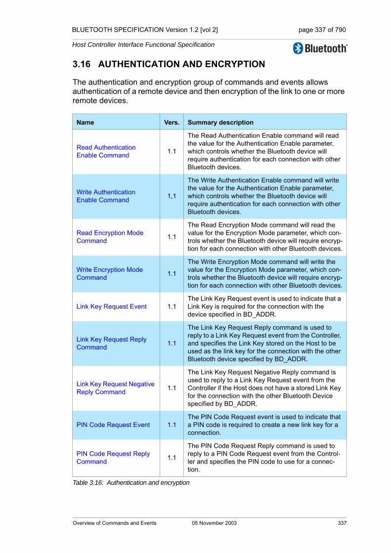
BLUETOOTH SPECIFICATION Version 1.2 [vol 2] page 337 of 790
Host Controller Interface Functional Specification
3.16 AUTHENTICATION AND ENCRYPTION
The authentication and encryption group of commands and events allows authentication of a remote device and then encryption of the link to one or more remote devices.
Name Vers. Summary description
Read Authentication Enable Command 1.1
The Read Authentication Enable command will read the value for the Authentication Enable parameter, which controls whether the Bluetooth device will require authentication for each connection with other Bluetooth devices.
Write Authentication Enable Command 1,1
The Write Authentication Enable command will write the value for the Authentication Enable parameter, which controls whether the Bluetooth device will require authentication for each connection with other Bluetooth devices.
Read Encryption Mode Command 1.1
The Read Encryption Mode command will read the value for the Encryption Mode parameter, which con-trols whether the Bluetooth device will require encryp-tion for each connection with other Bluetooth devices.
Write Encryption Mode Command 1.1
The Write Encryption Mode command will write the value for the Encryption Mode parameter, which con-trols whether the Bluetooth device will require encryp-tion for each connection with other Bluetooth devices.
Link Key Request Event 1.1The Link Key Request event is used to indicate that a Link Key is required for the connection with the device specified in BD_ADDR.
Link Key Request Reply Command 1.1
The Link Key Request Reply command is used to reply to a Link Key Request event from the Controller, and specifies the Link Key stored on the Host to be used as the link key for the connection with the other Bluetooth device specified by BD_ADDR.
Link Key Request Negative Reply Command 1.1
The Link Key Request Negative Reply command is used to reply to a Link Key Request event from the Controller if the Host does not have a stored Link Key for the connection with the other Bluetooth Device specified by BD_ADDR.
PIN Code Request Event 1.1The PIN Code Request event is used to indicate that a PIN code is required to create a new link key for a connection.
PIN Code Request Reply Command 1.1
The PIN Code Request Reply command is used to reply to a PIN Code Request event from the Control-ler and specifies the PIN code to use for a connec-tion.
Table 3.16: Authentication and encryption
Overview of Commands and Events 05 November 2003 337

BLUETOOTH SPECIFICATION Version 1.2 [vol 2] page 338 of 790
Host Controller Interface Functional Specification
PIN Code Request Nega-tive Reply Command 1.1
The PIN Code Request Negative Reply command is used to reply to a PIN Code Request event from the Controller when the Host cannot specify a PIN code to use for a connection.
Link Key Notification Event 1.1The Link Key Notification event is used to indicate to the Host that a new Link Key has been created for the connection with the device specified in BD_ADDR.
Authentication Requested Command 1.1
The Authentication Requested command is used to establish authentication between the two devices associated with the specified Connection Handle.
Authentication Complete Event 1.1
The Authentication Complete event occurs when authentication has been completed for the specified connection.
Set Connection Encryption Command 1.1 The Set Connection Encryption command is used to
enable and disable the link level encryption.
Encryption Change Event 1.1
The Encryption Change event is used to indicate that the change in the encryption has been completed for the Connection Handle specified by the Connection Handle event parameter.
Change Connection Link Key Command 1.1
The Change Connection Link Key command is used to force both devices of a connection associated to the connection handle, to generate a new link key.
Change Connection Link Key Complete Event 1.1
The Change Connection Link Key Complete event is used to indicate that the change in the Link Key for the Connection Handle specified by the Connection Handle event parameter had been completed.
Master Link Key Command 1.1
The Master Link Key command is used to force both devices of a connection associated to the connection handle to use the temporary link key of the Master device or the regular link keys.
Master Link Key Complete Event 1.1
The Master Link Key Complete event is used to indi-cate that the change in the temporary Link Key or in the semi-permanent link keys on the Bluetooth mas-ter side has been completed.
Read PIN Type Command 1.1The Read PIN Type command is used for the Host to read the value that is specified to indicate whether the Host supports variable PIN or only fixed PINs.
Write PIN Type Command 1.1The Write PIN Type command is used for the Host to specify whether the Host supports variable PIN or only fixed PINs.
Read Stored Link Key Command 1.1
The Read Stored Link Key command provides the ability to read one or more link keys stored in the Controller.
Name Vers. Summary description
Table 3.16: Authentication and encryption
338 05 November 2003 Overview of Commands and Events

BLUETOOTH SPECIFICATION Version 1.2 [vol 2] page 339 of 790
Host Controller Interface Functional Specification
3.17 TESTING
The testing group of commands and events allows a device to be placed into a special testing mode to allow for testing to be performed.
Return Link Keys Event 1.1The Return Link Keys event is used to return stored link keys after a Read Stored Link Key command is used.
Write Stored Link Key Command 1.1
The Write Stored Link Key command provides the ability to write one or more link keys to be stored in the Controller.
Delete Stored Link Key Command 1.1
The Delete Stored Link Key command provides the ability to remove one or more of the link keys stored in the Controller.
Create New Unit Key Com-mand 1.1 The Create New Unit Key command is used to create
a new unit key.
Name Vers. Summary description
Read Loopback Mode Command 1.1
The Read Loopback Mode will read the value for the setting of the Controllers Loopback Mode. The setting of the Loopback Mode will determine the path of information.
Write Loopback Mode Command 1.1
The Write Loopback Mode will write the value for the setting of the Controllers Loopback Mode. The setting of the Loopback Mode will determine the path of information.
Loopback Command Event 1.1The Loopback Command event is used to loop back all commands that the Host sends to the Controller with some exceptions.
Enable Device Under Test Mode Command 1.1
The Enable Device Under Test Mode command will allow the local Bluetooth module to enter test mode via LMP test commands. The Host issues this com-mand when it wants the local device to be the DUT for the Testing scenarios as described in the Blue-tooth Test Mode document.
Table 3.17: Testing
Name Vers. Summary description
Table 3.16: Authentication and encryption
Overview of Commands and Events 05 November 2003 339
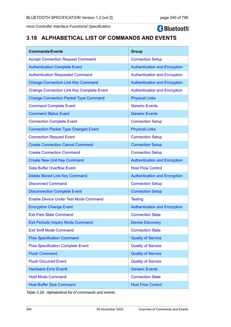
BLUETOOTH SPECIFICATION Version 1.2 [vol 2] page 340 of 790
Host Controller Interface Functional Specification
3.18 ALPHABETICAL LIST OF COMMANDS AND EVENTS
Commands/Events Group
Accept Connection Request Command Connection Setup
Authentication Complete Event Authentication and Encryption
Authentication Requested Command Authentication and Encryption
Change Connection Link Key Command Authentication and Encryption
Change Connection Link Key Complete Event Authentication and Encryption
Change Connection Packet Type Command Physical Links
Command Complete Event Generic Events
Command Status Event Generic Events
Connection Complete Event Connection Setup
Connection Packet Type Changed Event Physical Links
Connection Request Event Connection Setup
Create Connection Cancel Command Connection Setup
Create Connection Command Connection Setup
Create New Unit Key Command Authentication and Encryption
Data Buffer Overflow Event Host Flow Control
Delete Stored Link Key Command Authentication and Encryption
Disconnect Command Connection Setup
Disconnection Complete Event Connection Setup
Enable Device Under Test Mode Command Testing
Encryption Change Event Authentication and Encryption
Exit Park State Command Connection State
Exit Periodic Inquiry Mode Command Device Discovery
Exit Sniff Mode Command Connection State
Flow Specification Command Quality of Service
Flow Specification Complete Event Quality of Service
Flush Command Quality of Service
Flush Occurred Event Quality of Service
Hardware Error Eventt Generic Events
Hold Mode Command Connection State
Host Buffer Size Command Host Flow Control
Table 3.18: Alphabetical list of commands and events.
340 05 November 2003 Overview of Commands and Events

BLUETOOTH SPECIFICATION Version 1.2 [vol 2] page 341 of 790
Host Controller Interface Functional Specification
Host Number Of Completed Packets Command Host Flow Control
Inquiry Cancel Command Device Discovery
Inquiry Command Device Discovery
Inquiry Complete Event Device Discovery
Inquiry Result Event Device Discovery
Inquiry Result with RSSI Event Device Discovery
Link Key Notification Event Authentication and Encryption
Link Key Request Event Authentication and Encryption
Link Key Request Negative Reply Command Authentication and Encryption
Link Key Request Reply Command Authentication and Encryption
Loopback Command Event Testing
Master Link Key Command Authentication and Encryption
Master Link Key Complete Event Authentication and Encryption
Max Slots Change Event Connection State
Mode Change Event Connection State
Number Of Completed Packets Event Controller Flow Control
Page Scan Repetition Mode Change Event Connection Setup
Park State Command Connection State
Periodic Inquiry Mode Command Device Discovery
PIN Code Request Event Authentication and Encryption
PIN Code Request Negative Reply Command Authentication and Encryption
PIN Code Request Reply Command Authentication and Encryption
QoS Setup Command Quality of Service
QoS Setup Complete Event Quality of Service
QoS Violation Event Quality of Service
Read AFH Channel Assessment Mode Command Physical Links
Read AFH Channel Map Command Link Information
Read Authentication Enable Command Authentication and Encryption
Read Automatic Flush Timeout Command Quality of Service
Read BD_ADDR Command Controller Information
Read Buffer Size Command Controller Flow Control
Read Class of Device Command Controller Information
Commands/Events Group
Table 3.18: Alphabetical list of commands and events.
Overview of Commands and Events 05 November 2003 341
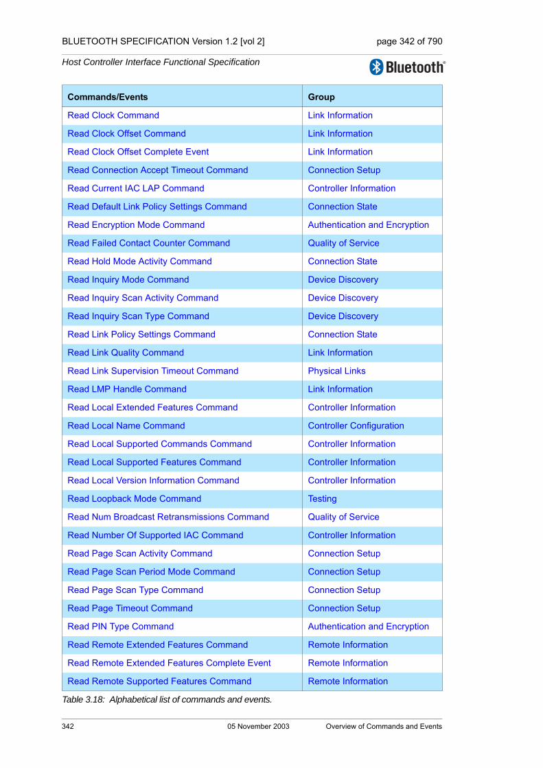
BLUETOOTH SPECIFICATION Version 1.2 [vol 2] page 342 of 790
Host Controller Interface Functional Specification
Read Clock Command Link Information
Read Clock Offset Command Link Information
Read Clock Offset Complete Event Link Information
Read Connection Accept Timeout Command Connection Setup
Read Current IAC LAP Command Controller Information
Read Default Link Policy Settings Command Connection State
Read Encryption Mode Command Authentication and Encryption
Read Failed Contact Counter Command Quality of Service
Read Hold Mode Activity Command Connection State
Read Inquiry Mode Command Device Discovery
Read Inquiry Scan Activity Command Device Discovery
Read Inquiry Scan Type Command Device Discovery
Read Link Policy Settings Command Connection State
Read Link Quality Command Link Information
Read Link Supervision Timeout Command Physical Links
Read LMP Handle Command Link Information
Read Local Extended Features Command Controller Information
Read Local Name Command Controller Configuration
Read Local Supported Commands Command Controller Information
Read Local Supported Features Command Controller Information
Read Local Version Information Command Controller Information
Read Loopback Mode Command Testing
Read Num Broadcast Retransmissions Command Quality of Service
Read Number Of Supported IAC Command Controller Information
Read Page Scan Activity Command Connection Setup
Read Page Scan Period Mode Command Connection Setup
Read Page Scan Type Command Connection Setup
Read Page Timeout Command Connection Setup
Read PIN Type Command Authentication and Encryption
Read Remote Extended Features Command Remote Information
Read Remote Extended Features Complete Event Remote Information
Read Remote Supported Features Command Remote Information
Commands/Events Group
Table 3.18: Alphabetical list of commands and events.
342 05 November 2003 Overview of Commands and Events

BLUETOOTH SPECIFICATION Version 1.2 [vol 2] page 343 of 790
Host Controller Interface Functional Specification
Read Remote Supported Features Complete Event Remote Information
Read Remote Version Information Command Remote Information
Read Remote Version Information Complete Event Remote Information
Read RSSI Command Link Information
Read Scan Enable Command Controller Information
Read Stored Link Key Command Authentication and Encryption
Read Synchronous Flow Control Enable Command Host Flow Control
Read Transmit Power Level Command Link Information
Read Voice Setting Command Synchronous Connections
Reject Connection Request Command Connection Setup
Remote Name Request Cancel Command Remote Information
Remote Name Request Command Remote Information
Remote Name Request Complete Event Remote Information
Reset Command Device Setup
Reset Failed Contact Counter Command Quality of Service
Return Link Keys Event Authentication and Encryption
Role Change Event Piconet Structure
Role Discovery Command Piconet Structure
Set AFH Host Channel Classification Command Physical Links
Set Connection Encryption Command Authentication and Encryption
Set Controller To Host Flow Control Command Host Flow Control
Set Event Filter Command Host Flow Control
Set Event Mask Command Host Flow Control
Setup Synchronous Connection Command Synchronous Connections
Sniff Mode Command Connection State
Switch Role Command Piconet Structure
Synchronous Connection Changed event Synchronous Connections
Synchronous Connection Complete Event Synchronous Connections
Write AFH Channel Assessment Mode Command Physical Links
Write Authentication Enable Command Authentication and Encryption
Write Automatic Flush Timeout Command Quality of Service
Write Class of Device Command Controller Information
Commands/Events Group
Table 3.18: Alphabetical list of commands and events.
Overview of Commands and Events 05 November 2003 343
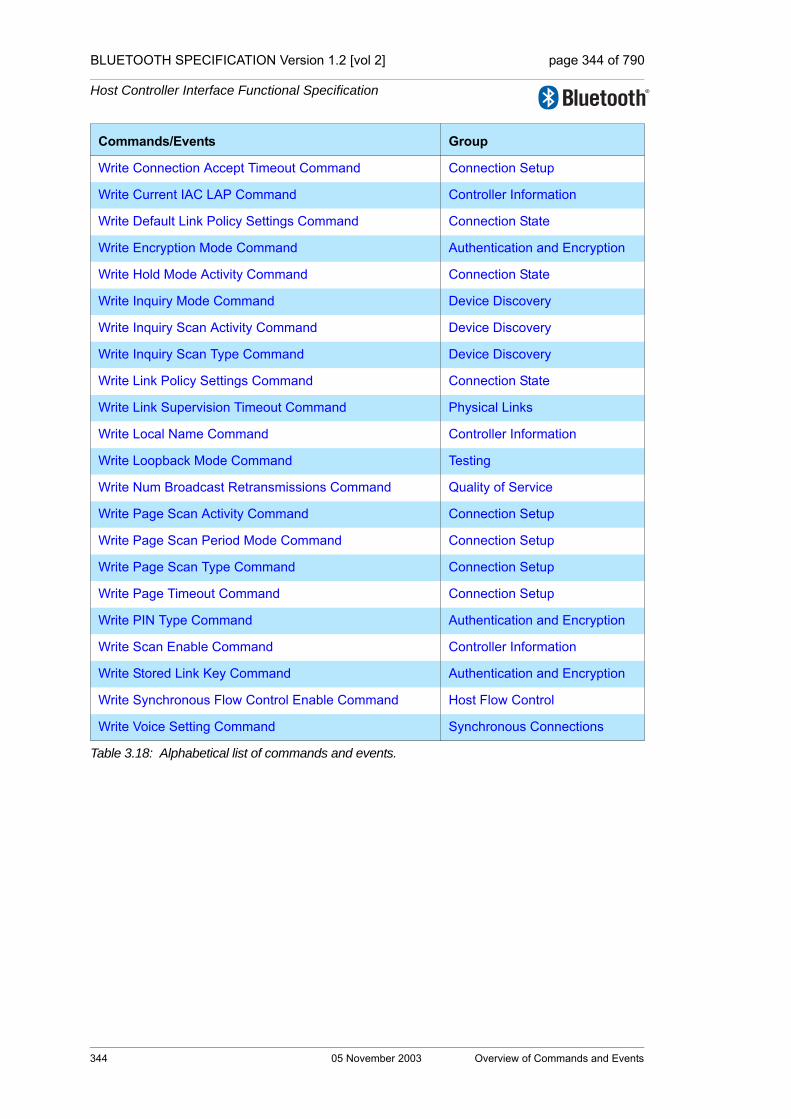
BLUETOOTH SPECIFICATION Version 1.2 [vol 2] page 344 of 790
Host Controller Interface Functional Specification
Write Connection Accept Timeout Command Connection Setup
Write Current IAC LAP Command Controller Information
Write Default Link Policy Settings Command Connection State
Write Encryption Mode Command Authentication and Encryption
Write Hold Mode Activity Command Connection State
Write Inquiry Mode Command Device Discovery
Write Inquiry Scan Activity Command Device Discovery
Write Inquiry Scan Type Command Device Discovery
Write Link Policy Settings Command Connection State
Write Link Supervision Timeout Command Physical Links
Write Local Name Command Controller Information
Write Loopback Mode Command Testing
Write Num Broadcast Retransmissions Command Quality of Service
Write Page Scan Activity Command Connection Setup
Write Page Scan Period Mode Command Connection Setup
Write Page Scan Type Command Connection Setup
Write Page Timeout Command Connection Setup
Write PIN Type Command Authentication and Encryption
Write Scan Enable Command Controller Information
Write Stored Link Key Command Authentication and Encryption
Write Synchronous Flow Control Enable Command Host Flow Control
Write Voice Setting Command Synchronous Connections
Commands/Events Group
Table 3.18: Alphabetical list of commands and events.
344 05 November 2003 Overview of Commands and Events
BLUETOOTH SPECIFICATION Version 1.2 [vol 2] page 345 of 790
Host Controller Interface Functional Specification
4 HCI FLOW CONTROL
Flow control shall be used in the direction from the Host to the Controller to avoid overflowing the Controller data buffers with ACL data destined for a remote device (using a connection handle) that is not responding. The Host manages the data buffers of the Controller.
4.1 HOST TO CONTROLLER DATA FLOW CONTROL
On initialization, the Host shall issue the Read Buffer Size command. Two of the return parameters of this command determine the maximum size of HCI ACL and synchronous Data Packets (excluding header) sent from the Host to the Controller. There are also two additional return parameters that specify the total number of HCI ACL and synchronous Data Packets that the Controller may have waiting for transmission in its buffers.
When there is at least one connection to another device, or when in local loop-back mode, the Controller shall use the Number Of Completed Packets event to control the flow of data from the Host. This event contains a list of connection handles and a corresponding number of HCI Data Packets that have been completed (transmitted, flushed, or looped back to the Host) since the previous time the event was returned (or since the connection was established, if the event has not been returned before for a particular connection handle).
Based on the information returned in this event, and the return parameters of the Read Buffer Size command that specify the total number of HCI ACL and synchronous Data Packets that can be stored in the Controller, the Host decides for which Connection Handles the following HCI Data Packets should be sent.
Every time it has sent an HCI Data Packet, the Host shall assume that the free buffer space for the corresponding link type (ACL, SCO or eSCO) in the Con-troller has decreased by one HCI Data Packet.
Each Number Of Completed Packets event received by the Host provides information about how many HCI Data Packets have been completed (trans-mitted or flushed) for each Connection Handle since the previous Number Of Completed Packets event was sent to the Host. It can then calculate the actual current buffer usage.
When the Controller has completed one or more HCI Data Packet(s) it shall send a Number Of Completed Packets event to the Host, until it finally reports that all the pending HCI Data Packets have been completed. The frequency at which this event is sent is manufacturer specific.
Note: The Number Of Completed Packets events will not report on synchro-nous connection handles if Synchronous Flow Control is disabled. (See Read/
HCI Flow Control 05 November 2003 345

BLUETOOTH SPECIFICATION Version 1.2 [vol 2] page 346 of 790
Host Controller Interface Functional Specification
Write Synchronous Flow Control Enable, Section 7.3.38 on page 486 and Sec-tion 7.3.39 on page 487)
For each individual Connection Handle, the data must be sent to the Controller in HCI Data Packets in the order in which it was created in the Host. The Con-troller shall also transmit data on the air that is received from the Host for a given Connection Handle in the same order as it is received from the Host.
Data that is received on the air from another device shall, for the corresponding Connection Handle, be sent in HCI Data Packets to the Host in the same order as it is received. This means the scheduling shall be decided separately for each Connection Handle basis. For each individual Connection Handle, the order of the data shall not be changed from the order in which the data has been created.
4.2 CONTROLLER TO HOST DATA FLOW CONTROL
In some implementations, flow control may also be necessary in the direction from the Controller to the Host. The Set Host Controller To Host Flow Control command can be used to turn flow control on or off in that direction.
On initialization, the Host uses the Host Buffer Size command to notify the Controller about the maximum size of HCI ACL and synchronous Data Packets sent from the Controller to the Host. The command also contains two additional command parameters to notify the Controller about the total number of ACL and synchronous Data Packets that can be stored in the data buffers of the Host.
The Host uses the Host Number Of Completed Packets command in exactly the same way as the Controller uses the Number Of Completed Packets event as was previously described in this section.
The Host Number Of Completed Packets command is a special command for which no command flow control is used, and which can be sent anytime there is a connection or when in local loopback mode. The command also has no event after the command has completed. This makes it possible for the flow control to work in exactly the same way in both directions, and the flow of nor-mal commands will not be disturbed.
346 05 November 2003 HCI Flow Control
BLUETOOTH SPECIFICATION Version 1.2 [vol 2] page 347 of 790
Host Controller Interface Functional Specification
4.3 DISCONNECTION BEHAVIOUR
When the Host receives a Disconnection Complete event, the Host shall assume that all unacknowledged HCI Data Packets that have been sent to the Controller for the returned Connection Handle have been flushed, and that the corresponding data buffers have been freed. The Controller does not have to notify the Host about this in a Number Of Completed Packets event.
If flow control is also enabled in the direction from the Controller to the Host, the Controller may, after it has sent a Disconnection Complete event, assume that the Host will flush its data buffers for the sent Connection Handle when it receives the Disconnection Complete event. The Host does not have to notify the Controller about this in a Host Number Of Completed Packets command.
4.4 COMMAND FLOW CONTROL
On initial power-on, and after a reset, the Host shall send a maximum of one outstanding HCI Command Packet until a Command Complete or Command Status event has been received.
The Command Complete and Command Status events contain a parameter called Num HCI Command Packets, which indicates the number of HCI Com-mand Packets the Host is currently allowed to send to the Controller. The Con-troller may buffer one or more HCI command packets, but the Controller must start performing the commands in the order in which they are received. The Con-troller can start performing a command before it completes previous commands. Therefore, the commands do not always complete in the order they are started.
To indicate to the Host that the Controller is ready to receive HCI command packets, the Controller may generate a Command Complete event with the Command Opcode 0x0000, and the Num HCI Command Packets event parameter is set to 1 or more. Command Opcode 0x0000 is a NOP (No OPera-tion), and can be used to change the number of outstanding HCI command packets that the Host can send. The Controller may generate a Command Complete event with the Num HCI Command Packets event parameter set to zero to inform Host it must stop sending commands.
For most commands, a Command Complete event shall be sent to the Host when the Controller completes the command. Some commands are executed in the background and do not return a Command Complete event when they have been completed. Instead, the Controller shall send a Command Status event back to the Host when it has begun to execute the command. When the actions associated with the command have finished, an event that is associ-ated with the command shall be sent by the Controller to the Host.
If the command does not begin to execute (for example, if there was a parame-ter error or the command is currently not allowed), the Command Status event shall be returned with the appropriate error code in the Status parameter, and the event associated with the sent command shall not be returned.
HCI Flow Control 05 November 2003 347

BLUETOOTH SPECIFICATION Version 1.2 [vol 2] page 348 of 790
Host Controller Interface Functional Specification
4.5 COMMAND ERROR HANDLING
If an error occurs for a command for which a Command Complete event is returned, the Return Parameters field may not contain all the return parameters specified for the command. The Status parameter, which explains the error rea-son and which is the first return parameter, shall always be returned. If there is a Connection Handle parameter or a BD_ADDR parameter right after the Sta-tus parameter, this parameter shall also be returned so that the Host can iden-tify to which instance of a command the Command Complete event belongs. In this case, the Connection Handle or BD_ADDR parameter shall have exactly the same value as that in the corresponding command parameter. It is imple-mentation specific whether more parameters will be returned in case of an error.
The above also applies to commands that have associated command specific completion events with a status parameter in their completion event, with two exceptions. The exceptions are the Connection Complete and the Synchro-nous Connection Complete events. On failure, for these two events only, the second parameter, Connection_Handle, is not valid and the third parameter, BD_ADDR, is valid for identification purposes. The validity of other parameters is likewise implementation specific for failed commands in this group.
Note: The BD_ADDR return parameter of the command Read BD_ADDR is not used to identify to which instance of the Read BD ADDR command the Com-mand Complete event belongs. It is optional for the Controller to return this parameter in case of an error.
348 05 November 2003 HCI Flow Control
BLUETOOTH SPECIFICATION Version 1.2 [vol 2] page 349 of 790
Host Controller Interface Functional Specification
5 HCI DATA FORMATS
5.1 INTRODUCTIONThe HCI provides a uniform command method of accessing the Bluetooth capabil-ities. The HCI Link commands provide the Host with the ability to control the link layer connections to other Bluetooth devices. These commands typically involve the Link Manager (LM) to exchange LMP commands with remote Bluetooth devices. For details see “Link Manager Protocol” on page 189 [Part C].
The HCI Policy commands are used to affect the behavior of the local and remote LM. These Policy commands provide the Host with methods of influ-encing how the LM manages the piconet. The Controller & Baseband, Informa-tional, and Status commands provide the Host access to various registers in the Controller.
HCI commands may take different amounts of time to be completed. Therefore, the results of commands will be reported back to the Host in the form of an event. For example, for most HCI commands the Controller will generate the Command Complete event when a command is completed. This event con-tains the return parameters for the completed HCI command. For enabling the Host to detect errors on the HCI-Transport Layer, there needs to be a timeout between the transmission of the Host’s command and the reception of the Con-troller’s response (e.g. a Command Complete or Command Status event). Since the maximum response timeout is strongly dependent on the HCI-Trans-port Layer used, it is recommended to use a default value of one second for this timer. This amount of time is also dependent on the number of commands unprocessed in the command queue.
5.2 DATA AND PARAMETER FORMATS• All values are in Binary and Hexadecimal Little Endian formats unless other-
wise noted
• In addition, all parameters which can have negative values must use 2’s complement when specifying values
• Arrayed parameters are specified using the following notation: Parame-terA[i]. If more than one set of arrayed parameters are specified (e.g. ParameterA[i], ParameterB[i]), then the order of the parameters are as fol-lows: ParameterA[0], ParameterB[0], ParameterA[1], ParameterB[1], ParameterA[2], ParameterB[2], … ParameterA[n], ParameterB[n]
• Unless noted otherwise, all parameter values are sent and received in Little Endian format (i.e. for multi-octet parameters the rightmost (Least Significa-tion Octet) is transmitted first)
• All command and event parameters that are not-arrayed and all elements in an arrayed parameter have fixed sizes (an integer number of octets). The parameters and the size of each not arrayed parameter (or of each element in an arrayed parameter) contained in a command or an event is specified
HCI Data Formats 05 November 2003 349

BLUETOOTH SPECIFICATION Version 1.2 [vol 2] page 350 of 790
Host Controller Interface Functional Specification
for each command or event. The number of elements in an arrayed parame-ter is not fixed.
• Where bit strings are specified, the low order bit is the right hand bit, e.g. 0 is the low order bit in ‘10’.
5.3 CONNECTION HANDLES
Connection Handles are used to identify logical channels between the Host and Controller. Connection Handles are assigned by the Controller when a new logical link is created, using the Connection Complete or Synchronous Con-nection Complete events. Broadcast Connection Handles are handled differ-ently, and are described below.
The first time the Host sends an HCI Data Packet with Broadcast_Flag set to 01b (active broadcast) or 10b (piconet broadcast) after a power-on or a reset, the value of the Connection Handle parameter must be a value which is not currently assigned by the Host Controller. The Host must use different connec-tion handles for active broadcast and piconet broadcast.
The Host Controller must then continue to use the same connection handles for each type of broadcast until a reset is made. Note: The Host Controller must not send a Connection Complete event containing a new Connection_Handle that it knows is used for broadcast.
Note: In some situations, it may happen that the Host Controller sends a Con-nection Complete event before having interpreted a Broadcast packet received from the Host, and that the Connection_Handles of both Connection Complete event and HCI Data packet are the same. This conflict has to be avoided as fol-lows:
If a Connection Complete event is received containing one of the connection handles used for broadcast, the Host has to wait before sending any packets for the new connection until it receives a Number Of Completed Packets event indicating that there are no pending broadcast packets belonging to the con-nection handle. In addition, the Host must change the Connection_Handle used for the corresponding type of broadcast to a Connection_Handle which is currently not assigned by the Host Controller.
This Connection_Handle must then be used for all the following broadcasts of that type until a reset is performed or the same conflict situation happens again. However, this will occur very rarely.
The Host Controller must, in the above conflict case, be able to distinguish between the Broadcast message sent by the Host and the new connection made (this could be even a new synchronous link) even though the connection handles are the same.
For an HCI Data Packet sent from the Host Controller to the Host where the Broadcast_Flag is 01 or 10, the Connection_Handle parameter should contain
350 05 November 2003 HCI Data Formats
BLUETOOTH SPECIFICATION Version 1.2 [vol 2] page 351 of 790
Host Controller Interface Functional Specification
the connection handle for the ACL connection to the master that sent the broadcast.
Note: Connection handles used for Broadcast do not identify an ACL point-to-point connection, so they must not be used in any command having a Connection_Handle parameter and they will not be returned in any event hav-ing a Connection_Handle parameter except the Number Of Completed Pack-ets event.
5.4 EXCHANGE OF HCI-SPECIFIC INFORMATION
The Host Controller Transport Layer provides transparent exchange of HCI specific information. These transporting mechanisms provide the ability for the Host to send HCI commands, ACL data and synchronous data to the Control-ler. These transport mechanisms also provide the ability for the Host to receive HCI events, ACL data and synchronous data from the Controller. Since the Host Controller Transport Layer provides transparent exchange of HCI-specific information, the HCI specification specifies the format of the commands, events, and data exchange between the Host and the Controller. The next sec-tions specify the HCI packet formats.
5.4.1 HCI Command Packet
The HCI Command Packet is used to send commands to the Controller from the Host. The format of the HCI Command Packet is shown in Figure 5.1, and the definition of each field is explained below.
The Controller must be able to accept HCI Command Packets with up to 255 bytes of data excluding the HCI Command Packet header.
Each command is assigned a 2 byte Opcode used to uniquely identify different types of commands. The Opcode parameter is divided into two fields, called the OpCode Group Field (OGF) and OpCode Command Field (OCF). The OGF occupies the upper 6 bits of the Opcode, while the OCF occupies the remaining 10 bits. The OGF of 0x3F is reserved for vendor-specific debug commands. The OGF of 0x3E is reserved for Bluetooth Logo Testing. The organization of the Opcodes allows additional information to be inferred without fully decoding the entire Opcode.
Note: the OGF composed of all ‘ones’ has been reserved for vendor-specific debug commands. These commands are vendor-specific and are used during manufacturing, for a possible method for updating firmware, and for debugging.
Note: the OGF composed of all ‘zeros’ and an OCF or all ‘zeros’ is the NOP command. This command Opcode may be used in Command Flow Control. (See Section 4.4 on page 347)
HCI Data Formats 05 November 2003 351

BLUETOOTH SPECIFICATION Version 1.2 [vol 2] page 352 of 790
Host Controller Interface Functional Specification
Figure 5.1: HCI Command Packet
Op_Code: Size: 2 Octets
Parameter_Total_Length: Size: 1 Octet
Parameter 0 - N: Size: Parameter Total Length
Value Parameter Description
0xXXXX OGFRange (6 bits): 0x00-0x3F (0x3E reserved for Bluetooth logo testing and 0x3F reserved for vendor-specific debug commands) OCF Range (10 bits): 0x0000-0x03FF
Value Parameter Description
0xXX Lengths of all of the parameters contained in this packet measured in octets. (N.B.: total length of parameters, not number of parameters)
Value Parameter Description
0xXX Each command has a specific number of parameters associated with it. These parameters and the size of each of the parameters are defined for each command. Each parameter is an integer number of octets in size.
4 8 12 16 20 24 28 31
OGFOCFParameter Total
LengthParameter 0
Parameter 1 Parameter ...
Parameter N-1
OpCode
Parameter N
0
352 05 November 2003 HCI Data Formats

BLUETOOTH SPECIFICATION Version 1.2 [vol 2] page 353 of 790
Host Controller Interface Functional Specification
5.4.2 HCI ACL Data Packets
HCI ACL Data Packets are used to exchange data between the Host and Con-troller. The format of the HCI ACL Data Packet is shown in Figure 5.2. The def-inition for each of the fields in the data packets is explained below.
Figure 5.2: HCI ACL Data Packet
Connection_Handle: Size: 12 Bits
Flags: Size: 2 Bits
The Flag Bits consist of the Packet_Boundary_Flag and Broadcast_Flag. The Packet_Boundary_Flag is located in bit 4 and bit 5, and the Broadcast_Flag is located in bit 6 and 7 in the second octet of the HCI ACL Data packet.
Packet_Boundary_Flag: Size: 2 Bits
Value Parameter Description
0xXXX Connection Handle to be used for transmitting a data packet or segment.Range: 0x0000-0x0EFF (0x0F00 - 0x0FFF Reserved for future use)
Value Parameter Description
00 Reserved for future use
01 Continuing fragment packet of Higher Layer Message
10 First packet of Higher Layer Message (i.e. start of an L2CAP packet)
11 Reserved for future use
Data
0 4 8 12 16 20 24 28 31
Connection Handle PBFlag
BCFlag
Data Total Length
HCI Data Formats 05 November 2003 353

BLUETOOTH SPECIFICATION Version 1.2 [vol 2] page 354 of 790
Host Controller Interface Functional Specification
Broadcast_Flag (in packet from Host to Controller): Size: 2 Bits
Broadcast_Flag (in packet from Controller to Host ): Size: 2 Bits
Note: active slave broadcast packets may be sent in park beacon slots.
Note: slaves in sniff mode may or may not receive a broadcast packet depend-ing on whether they happen to be listening at sniff slots, when the packet is sent.
Data_Total_Length: Size: 2 Octets
Value Parameter Description
00 No broadcast. Only point-to-point.
01 Active Slave Broadcast: packet is sent to all active slaves (i.e. packet is usually not sent during park beacon slots), and it may be received by slaves in sniff mode or park state.
10 Parked Slave Broadcast: packet is sent to all slaves and all slaves in park state (i.e. packet is sent during park beacon slots if there are parked slaves), and it may be received by slaves in sniff mode.
11 Reserved for future use.
Value Parameter Description
00 Point-to-point
01 Packet received as a slave not in park state (either Active Slave Broadcast or Parked Slave Broadcast)
10 Packet received as a slave in park state (Parked Slave Broadcast)
11 Reserved for future use.
Value Parameter Description
0xXXXX Length of data measured in octets.
354 05 November 2003 HCI Data Formats
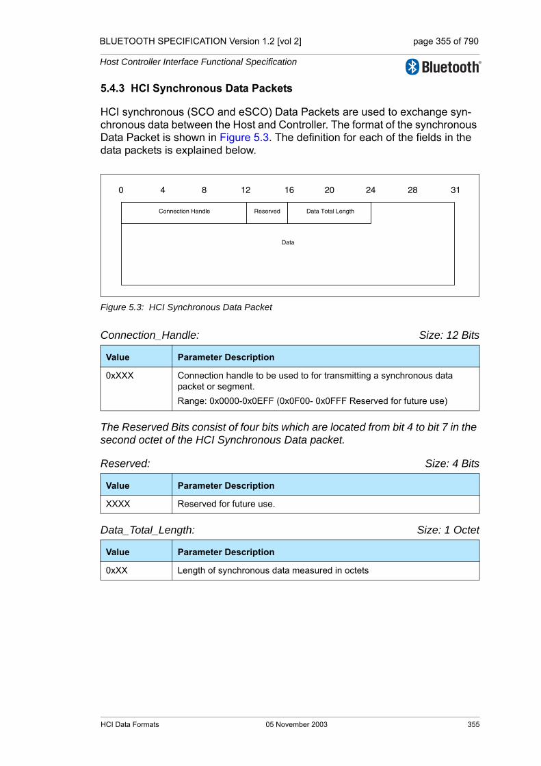
BLUETOOTH SPECIFICATION Version 1.2 [vol 2] page 355 of 790
Host Controller Interface Functional Specification
5.4.3 HCI Synchronous Data Packets
HCI synchronous (SCO and eSCO) Data Packets are used to exchange syn-chronous data between the Host and Controller. The format of the synchronous Data Packet is shown in Figure 5.3. The definition for each of the fields in the data packets is explained below.
Figure 5.3: HCI Synchronous Data Packet
Connection_Handle: Size: 12 Bits
The Reserved Bits consist of four bits which are located from bit 4 to bit 7 in the second octet of the HCI Synchronous Data packet.
Reserved: Size: 4 Bits
Data_Total_Length: Size: 1 Octet
Value Parameter Description
0xXXX Connection handle to be used to for transmitting a synchronous data packet or segment.Range: 0x0000-0x0EFF (0x0F00- 0x0FFF Reserved for future use)
Value Parameter Description
XXXX Reserved for future use.
Value Parameter Description
0xXX Length of synchronous data measured in octets
Data
0 4 8 12 16 20 24 28 31
Connection Handle Reserved Data Total Length
HCI Data Formats 05 November 2003 355

BLUETOOTH SPECIFICATION Version 1.2 [vol 2] page 356 of 790
Host Controller Interface Functional Specification
5.4.4 HCI Event Packet
The HCI Event Packet is used by the Controller to notify the Host when events occur. The Host must be able to accept HCI Event Packets with up to 255 octets of data excluding the HCI Event Packet header. The format of the HCI Event Packet is shown in Figure 5.4, and the definition of each field is explained below.
Figure 5.4: HCI Event Packet
Event_Code: Size: 1 Octet
Parameter_Total_Length: Size: 1 Octet
Event_Parameter 0 - N: Size: Parameter Total Length
Value Parameter Description
0xXX Each event is assigned a 1-Octet event code used to uniquely identify dif-ferent types of events.Range: 0x00-0xFF (The event code 0xFF is reserved for the event code used for vendor-specific debug events. In addition, the event code 0xFE is also reserved for Bluetooth Logo Testing)
Value Parameter Description
0xXX Length of all of the parameters contained in this packet, measured in octets
Value Parameter Description
0xXX Each event has a specific number of parameters associated with it. These parameters and the size of each of the parameters are defined for each event. Each parameter is an integer number of octets in size.
0 4 8 12 16 20 24 28 31
Event Code Event Parameter 0
Event Parameter 1
Parameter TotalLength
Event Parameter 3Event Parameter 2
Event Parameter N-1 Event Parameter N
356 05 November 2003 HCI Data Formats
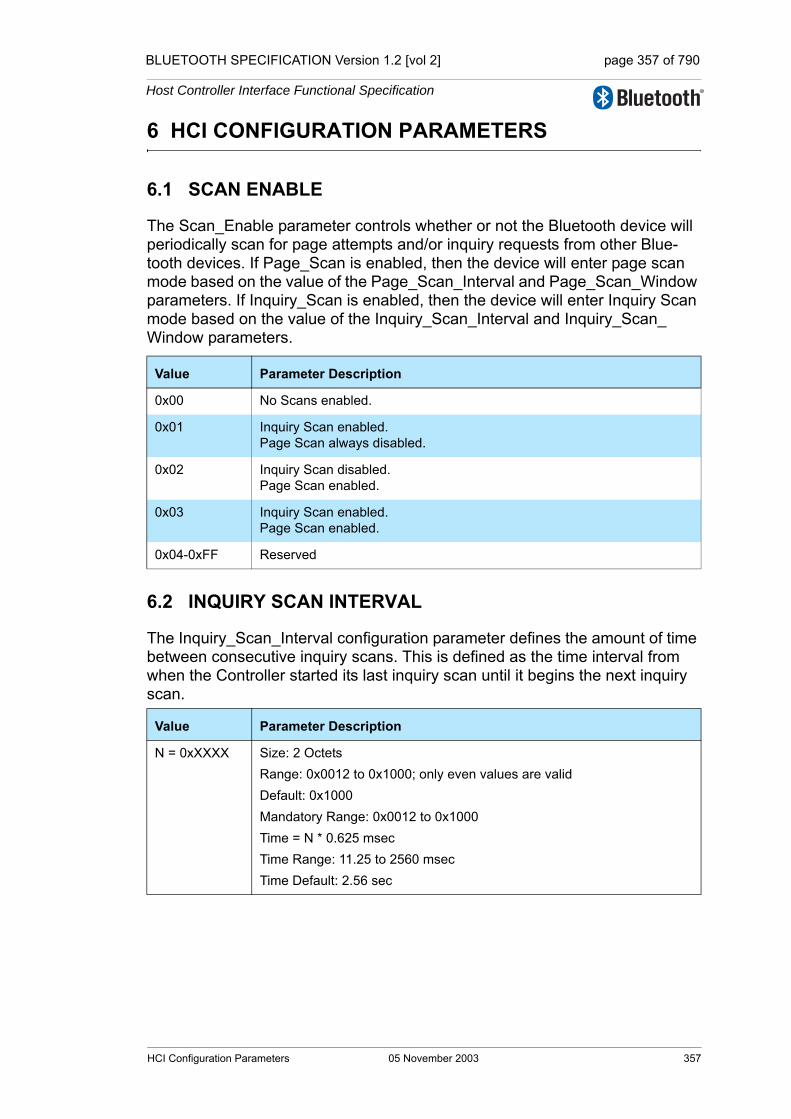
BLUETOOTH SPECIFICATION Version 1.2 [vol 2] page 357 of 790
Host Controller Interface Functional Specification
6 HCI CONFIGURATION PARAMETERS
6.1 SCAN ENABLE
The Scan_Enable parameter controls whether or not the Bluetooth device will periodically scan for page attempts and/or inquiry requests from other Blue-tooth devices. If Page_Scan is enabled, then the device will enter page scan mode based on the value of the Page_Scan_Interval and Page_Scan_Window parameters. If Inquiry_Scan is enabled, then the device will enter Inquiry Scan mode based on the value of the Inquiry_Scan_Interval and Inquiry_Scan_Window parameters.
6.2 INQUIRY SCAN INTERVAL
The Inquiry_Scan_Interval configuration parameter defines the amount of time between consecutive inquiry scans. This is defined as the time interval from when the Controller started its last inquiry scan until it begins the next inquiry scan.
Value Parameter Description
0x00 No Scans enabled.
0x01 Inquiry Scan enabled.Page Scan always disabled.
0x02 Inquiry Scan disabled.Page Scan enabled.
0x03 Inquiry Scan enabled.Page Scan enabled.
0x04-0xFF Reserved
Value Parameter Description
N = 0xXXXX Size: 2 OctetsRange: 0x0012 to 0x1000; only even values are validDefault: 0x1000Mandatory Range: 0x0012 to 0x1000Time = N * 0.625 msecTime Range: 11.25 to 2560 msecTime Default: 2.56 sec
HCI Configuration Parameters 05 November 2003 357

BLUETOOTH SPECIFICATION Version 1.2 [vol 2] page 358 of 790
Host Controller Interface Functional Specification
6.3 INQUIRY SCAN WINDOW
The Inquiry_Scan_Window configuration parameter defines the amount of time for the duration of the inquiry scan. The Inquiry_Scan_Window can only be less than or equal to the Inquiry_Scan_Interval.
6.4 INQUIRY SCAN TYPE
The Inquiry_Scan_Type configuration parameter indicates whether inquiry scanning will be done using non-interlaced scan or interlaced scan. Currently, one mandatory inquiry scan type and one optional inquiry scan type are defined. For details, see the Baseband Specification, “Inquiry scan substate” on page 144 [Part B].
6.5 INQUIRY MODE
The Inquiry_Mode configuration parameter indicates whether inquiry returns Inquiry Result events in the standard format or with RSSI.
Value Parameter Description
N = 0xXXXX Size: 2 OctetsRange: 0x0011 to 0x1000Default: 0x0012Mandatory Range: 0x0011 to Inquiry Scan IntervalTime = N * 0.625 msecTime Range: 10.625 msec to 2560 msecTime Default: 11.25 msec
Value Parameter Description
0x00 Mandatory: Standard Scan (default)
0x01 Optional: Interlaced Scan
0x02-0xFF Reserved
Value Parameter Description
0x00 Standard Inquiry Result event format
0x01 Inquiry Result format with RSSI
0x02-0xFF Reserved
358 05 November 2003 HCI Configuration Parameters
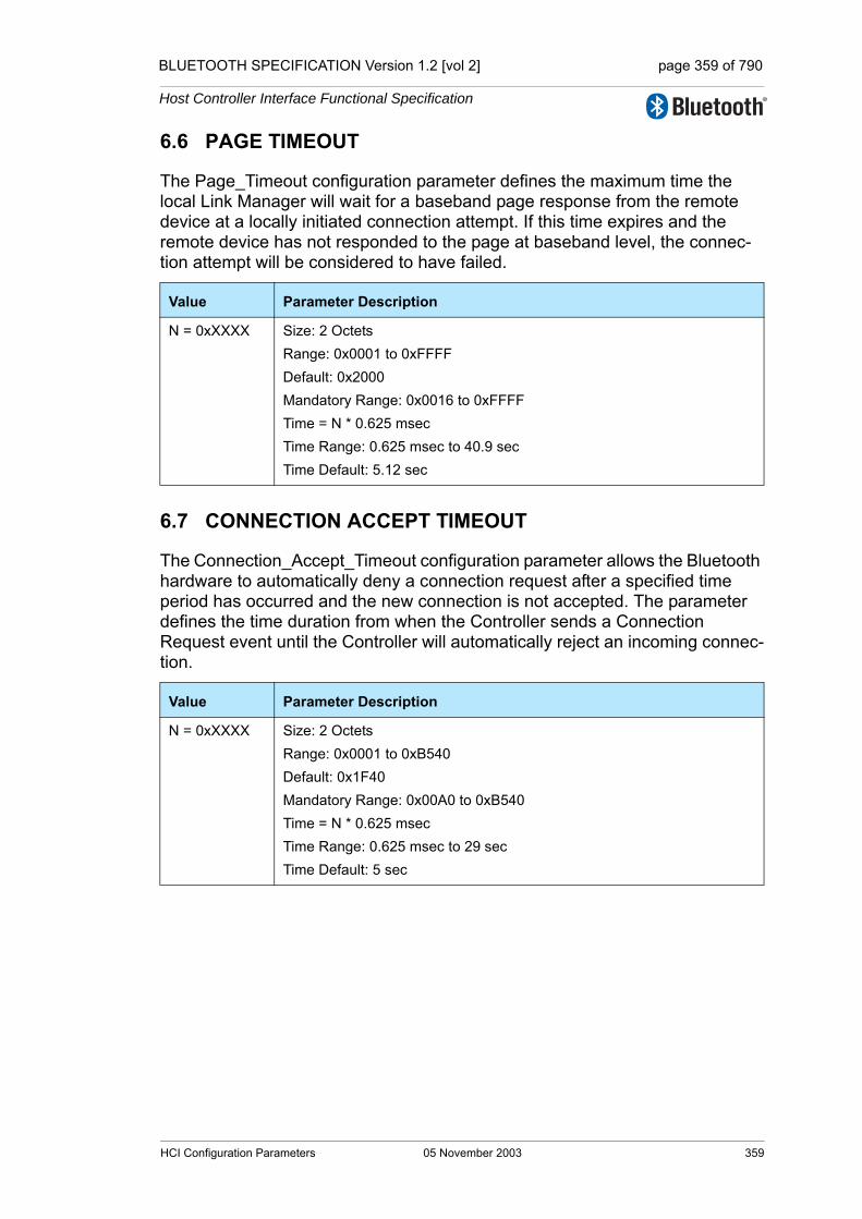
BLUETOOTH SPECIFICATION Version 1.2 [vol 2] page 359 of 790
Host Controller Interface Functional Specification
6.6 PAGE TIMEOUT
The Page_Timeout configuration parameter defines the maximum time the local Link Manager will wait for a baseband page response from the remote device at a locally initiated connection attempt. If this time expires and the remote device has not responded to the page at baseband level, the connec-tion attempt will be considered to have failed.
6.7 CONNECTION ACCEPT TIMEOUT
The Connection_Accept_Timeout configuration parameter allows the Bluetooth hardware to automatically deny a connection request after a specified time period has occurred and the new connection is not accepted. The parameter defines the time duration from when the Controller sends a Connection Request event until the Controller will automatically reject an incoming connec-tion.
Value Parameter Description
N = 0xXXXX Size: 2 OctetsRange: 0x0001 to 0xFFFFDefault: 0x2000Mandatory Range: 0x0016 to 0xFFFFTime = N * 0.625 msecTime Range: 0.625 msec to 40.9 secTime Default: 5.12 sec
Value Parameter Description
N = 0xXXXX Size: 2 OctetsRange: 0x0001 to 0xB540Default: 0x1F40Mandatory Range: 0x00A0 to 0xB540Time = N * 0.625 msecTime Range: 0.625 msec to 29 secTime Default: 5 sec
HCI Configuration Parameters 05 November 2003 359

BLUETOOTH SPECIFICATION Version 1.2 [vol 2] page 360 of 790
Host Controller Interface Functional Specification
6.8 PAGE SCAN INTERVALThe Page_Scan_Interval configuration parameter defines the amount of time between consecutive page scans. This time interval is defined from when the Controller started its last page scan until it begins the next page scan.
6.9 PAGE SCAN WINDOWThe Page_Scan_Window configuration parameter defines the amount of time for the duration of the page scan. The Page_Scan_Window can only be less than or equal to the Page_Scan_Interval.
6.10 PAGE SCAN PERIOD MODEEvery time an inquiry response message is sent, the Bluetooth device will start a timer (T_mandatory_pscan), the value of which is dependent on the Page_Scan_Period_Mode. As long as this timer has not expired, the Bluetooth device will use the mandatory page scan mode for all following page scans. Note: the timer T_mandatory_pscan will be reset at each new inquiry response. For details see the “Baseband Specification” on page 45 [Part B]. (Keyword: SP-Mode, FHS-Packet, T_mandatory_pscan, Inquiry-Response).
Value Parameter Description
N = 0xXXXX Size: 2 OctetsRange: 0x0012 to 0x1000; only even values are validDefault: 0x0800Mandatory Range: 0x0012 to 0x1000Time = N * 0.625 msecTime Range: 11.25 msec to 2560 msecTime Default: 1.28 sec
Value Parameter Description
N = 0xXXXX Size: 2 OctetsRange: 0x0011 to 0x1000Default: 0x0012Mandatory Range: 0x0011 to Page Scan IntervalTime = N * 0.625 msecTime Range: 10.625 msec to Page Scan IntervalTime Default: 11.25 msec
Value Parameter Description
0x00 P0
0x01 P1
0x02 P2
0x03-0xFF Reserved.
360 05 November 2003 HCI Configuration Parameters

BLUETOOTH SPECIFICATION Version 1.2 [vol 2] page 361 of 790
Host Controller Interface Functional Specification
6.11 PAGE SCAN TYPE
The Page_Scan_Type parameter indicates whether inquiry scanning will be done using non-interlaced scan or interlaced scan. For details, see the Base-band Specification, “Page scan substate” on page 134 [Part B].
6.12 VOICE SETTING
The Voice_Setting parameter controls all the various settings for voice connec-tions. The input settings apply to all voice connections, and cannot be set for individual voice connections. The Voice_Setting parameter controls the config-uration for voice connections: Input Coding, Air coding format, input data for-mat, Input sample size, and linear PCM parameter.The air coding format bits in the Voice_Setting command parameter specify which air coding format the local device requests. The air coding format bits do not specify which air coding format(s) the local device accepts when a remote device requests an air coding format. This is determined by the hardware capabilities of the local device.
Value Parameter Description
0x00 Mandatory: Standard Scan (default)
0x01 Optional: Interlaced Scan
0x02-0xFF Reserved
Value Parameter Description
00XXXXXXXX Input Coding: Linear
01XXXXXXXX Input Coding: µ-law Input Coding
10XXXXXXXX Input Coding: A-law Input Coding
11XXXXXXXX Reserved for Future Use
XX00XXXXXX Input Data Format: 1’s complement
XX01XXXXXX Input Data Format: 2’s complement
XX10XXXXXX Input Data Format: Sign-Magnitude
XX11XXXXXX Input Data Format: Unsigned
XXXX0XXXXX Input Sample Size: 8-bit (only for linear PCM)
XXXX1XXXXX Input Sample Size: 16-bit (only for linear PCM)
XXXXXnnnXX Linear_PCM_Bit_Pos: # bit positions that MSB of sample is away from starting at MSB (only for Liner PCM).
XXXXXXXX00 Air Coding Format: CVSD
XXXXXXXX01 Air Coding Format: µ-law
XXXXXXXX10 Air Coding Format: A-law
XXXXXXXX11 Air Coding Format: Transparent Data
HCI Configuration Parameters 05 November 2003 361
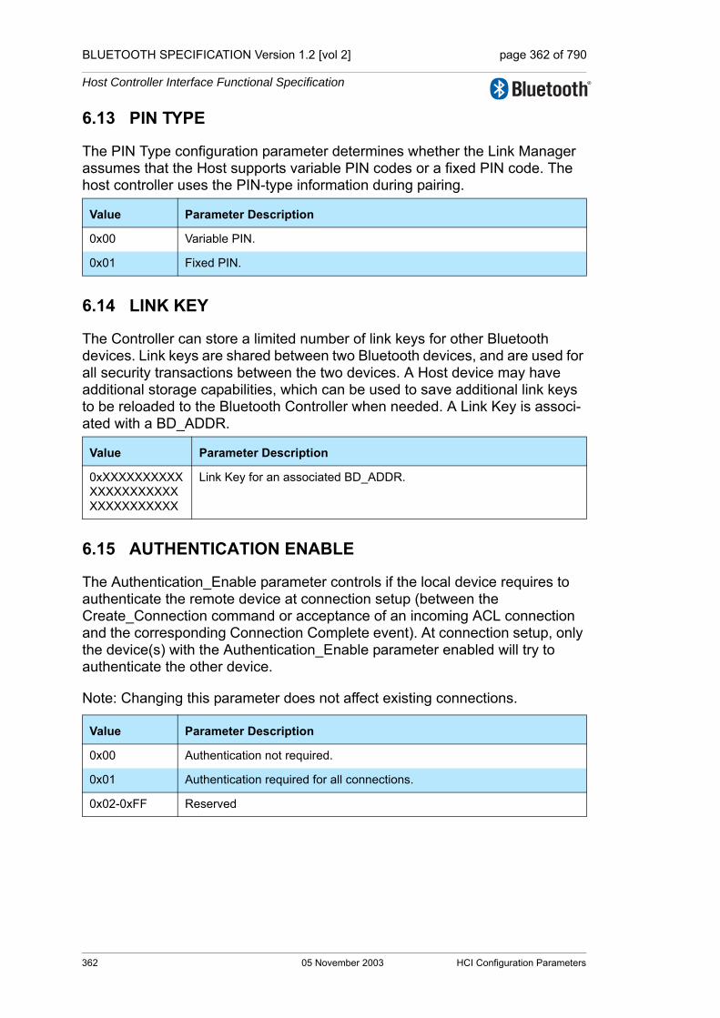
BLUETOOTH SPECIFICATION Version 1.2 [vol 2] page 362 of 790
Host Controller Interface Functional Specification
6.13 PIN TYPE
The PIN Type configuration parameter determines whether the Link Manager assumes that the Host supports variable PIN codes or a fixed PIN code. The host controller uses the PIN-type information during pairing.
6.14 LINK KEY
The Controller can store a limited number of link keys for other Bluetooth devices. Link keys are shared between two Bluetooth devices, and are used for all security transactions between the two devices. A Host device may have additional storage capabilities, which can be used to save additional link keys to be reloaded to the Bluetooth Controller when needed. A Link Key is associ-ated with a BD_ADDR.
6.15 AUTHENTICATION ENABLE
The Authentication_Enable parameter controls if the local device requires to authenticate the remote device at connection setup (between the Create_Connection command or acceptance of an incoming ACL connection and the corresponding Connection Complete event). At connection setup, only the device(s) with the Authentication_Enable parameter enabled will try to authenticate the other device.
Note: Changing this parameter does not affect existing connections.
Value Parameter Description
0x00 Variable PIN.
0x01 Fixed PIN.
Value Parameter Description
0xXXXXXXXXXXXXXXXXXXXXXXXXXXXXXXXX
Link Key for an associated BD_ADDR.
Value Parameter Description
0x00 Authentication not required.
0x01 Authentication required for all connections.
0x02-0xFF Reserved
362 05 November 2003 HCI Configuration Parameters

BLUETOOTH SPECIFICATION Version 1.2 [vol 2] page 363 of 790
Host Controller Interface Functional Specification
6.16 ENCRYPTION MODE
The Encryption_Mode parameter controls if the local device requires encryp-tion to the remote device at connection setup (between the Create_Connection command or acceptance of an incoming ACL connection and the correspond-ing Connection Complete event). At connection setup, only devices with the Authentication_Enabled configuration parameter set to required and the Encryption_Mode configuration parameter set to required will try to encrypt the physical link to the other device.
Note: Changing this parameter does not affect existing connections.
A temporary link key is used when both broadcast and point-to-point traffic are encrypted.
The Host must not specify the Encryption_Mode parameter with more encryp-tion capability than its local device currently supports, although the parameter is used to request the encryption capability to the remote device. Note that the Host must not request the command with the Encryption_Mode parameter set to 0x01, when the local device does not support encryption.
Note: for encryption to be used, both devices must support and enable encryp-tion.
Note: in the Connection Complete event the Encryption_Mode parameter will show whether encryption was successfully turned on. The remote device may not support encryption or may have set Encryption_Mode to 0x01 when the local device has not, so the encryption mode returned in the Connection Com-plete event may not equal the encryption mode set in the HCI_Write_Encryption_Mode Command.
Value Parameter Description
0x00 Encryption not required.
0x01 Encryption required for all connections.
0x02-0xFF Reserved.
HCI Configuration Parameters 05 November 2003 363
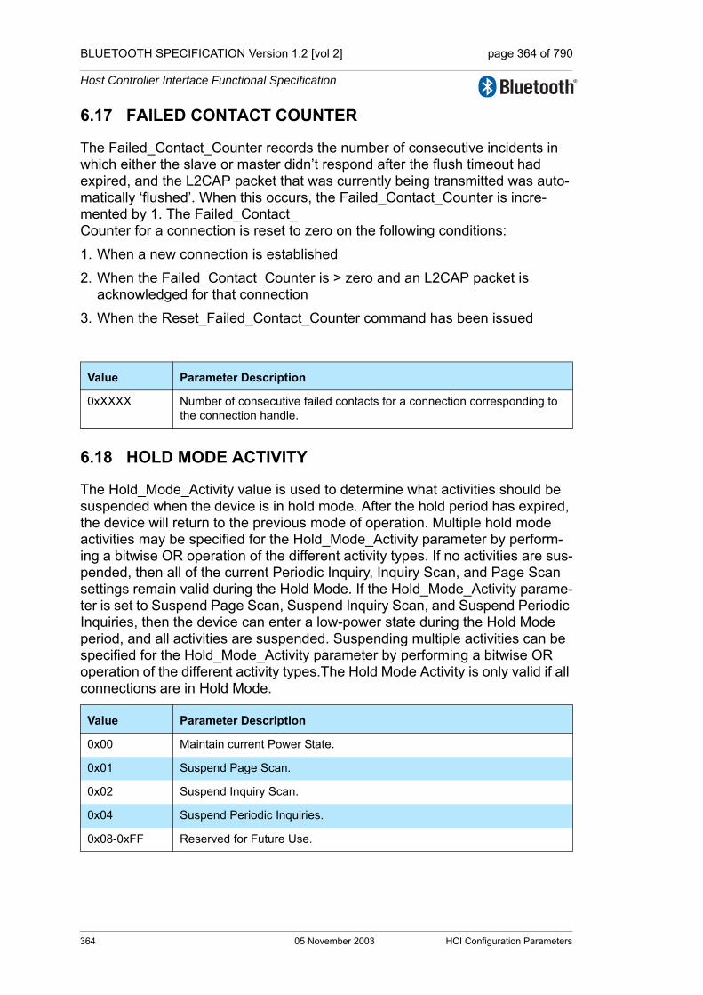
BLUETOOTH SPECIFICATION Version 1.2 [vol 2] page 364 of 790
Host Controller Interface Functional Specification
6.17 FAILED CONTACT COUNTER
The Failed_Contact_Counter records the number of consecutive incidents in which either the slave or master didn’t respond after the flush timeout had expired, and the L2CAP packet that was currently being transmitted was auto-matically ‘flushed’. When this occurs, the Failed_Contact_Counter is incre-mented by 1. The Failed_Contact_Counter for a connection is reset to zero on the following conditions:
1. When a new connection is established
2. When the Failed_Contact_Counter is > zero and an L2CAP packet is acknowledged for that connection
3. When the Reset_Failed_Contact_Counter command has been issued
6.18 HOLD MODE ACTIVITY
The Hold_Mode_Activity value is used to determine what activities should be suspended when the device is in hold mode. After the hold period has expired, the device will return to the previous mode of operation. Multiple hold mode activities may be specified for the Hold_Mode_Activity parameter by perform-ing a bitwise OR operation of the different activity types. If no activities are sus-pended, then all of the current Periodic Inquiry, Inquiry Scan, and Page Scan settings remain valid during the Hold Mode. If the Hold_Mode_Activity parame-ter is set to Suspend Page Scan, Suspend Inquiry Scan, and Suspend Periodic Inquiries, then the device can enter a low-power state during the Hold Mode period, and all activities are suspended. Suspending multiple activities can be specified for the Hold_Mode_Activity parameter by performing a bitwise OR operation of the different activity types.The Hold Mode Activity is only valid if all connections are in Hold Mode.
Value Parameter Description
0xXXXX Number of consecutive failed contacts for a connection corresponding to the connection handle.
Value Parameter Description
0x00 Maintain current Power State.
0x01 Suspend Page Scan.
0x02 Suspend Inquiry Scan.
0x04 Suspend Periodic Inquiries.
0x08-0xFF Reserved for Future Use.
364 05 November 2003 HCI Configuration Parameters

BLUETOOTH SPECIFICATION Version 1.2 [vol 2] page 365 of 790
Host Controller Interface Functional Specification
6.19 LINK POLICY SETTINGS
The Link_Policy_Settings parameter determines the behavior of the local Link Manager when it receives a request from a remote device or it determines itself to change the master-slave role or to enter park state, hold, or sniff mode. The local Link Manager will automatically accept or reject such a request from the remote device, and may even autonomously request itself, depending on the value of the Link_Policy_Settings parameter for the corresponding Connection_Handle. When the value of the Link_Policy_Settings parameter is changed for a certain Connection_Handle, the new value will only be used for requests from a remote device or from the local Link Manager itself made after this command has been completed. By enabling each mode individually, the Host can choose any combination needed to support various modes of opera-tion. Multiple LM policies may be specified for the Link_Policy_Settings param-eter by performing a bitwise OR operation of the different activity types.
Note: The local device may be forced into hold mode (regardless of whether the local device is master or slave) by the remote device regardless of the value of the Link_Policy_Settings parameter. The forcing of hold mode can however only be done once the connection has already been placed into hold mode through an LMP request (the Link_Policy_Settings determine if requests from a remote device should be accepted or rejected). The forcing of hold mode can after that be done as long as the connection lasts regardless of the setting for hold mode in the Link_Policy_Settings parameter.
Note that the previous description implies that if the implementation in the remote device is a "polite" implementation that does not force another device into hold mode via LMP PDUs, then the Link_Policy_Settings will never be overruled.
Value Parameter Description
0x0000 Disable All LM Modes Default
0x0001 Enable Role switch.
0x0002 Enable Hold Mode.
0x0004 Enable Sniff Mode.
0x0008 Enable Park State.
0x0010 – 0x8000
Reserved for Future Use.
HCI Configuration Parameters 05 November 2003 365

BLUETOOTH SPECIFICATION Version 1.2 [vol 2] page 366 of 790
Host Controller Interface Functional Specification
6.20 FLUSH TIMEOUT
The Flush_Timeout configuration parameter is used for ACL connections only. The Flush Timeout is defined in the Baseband specification Section 7.6.3, “Flushing payloads,” on page 130. This parameter allows ACL packets to be automatically flushed without the Host device issuing a Flush command. This provides support for isochronous data, such as audio. When the L2CAP packet that is currently being transmitted is automatically ‘flushed’, the Failed Contact Counter is incremented by one.
6.21 NUM BROADCAST RETRANSMISSIONS
Broadcast packets are not acknowledged and are unreliable. The Number of Broadcast Retransmissions parameter, N, is used to increase the reliability of a broadcast message by retransmitting the broadcast message multiple times. This parameter defines the number of times the device will retransmit a broad-cast data packet. This sets the value NBC in the baseband to one greater than the Num Broadcast Retransmissions value. (See Baseband Specification, Sec-tion 7.6.5, on page 130) This parameter should be adjusted as the link quality measurement changes.
Value Parameter Description
0 Timeout = ∞; No Automatic Flush
N = 0xXXXX Size: 2 OctetsRange: 0x0001 to 0x07FFMandatory Range: 0x0002 to 0x07FFTime = N * 0.625 msecTime Range: 0.625 msec to 1279.375 msec
Value Parameter Description
N = 0xXX NBC = N + 1
Range 0x00-0xFE
366 05 November 2003 HCI Configuration Parameters

BLUETOOTH SPECIFICATION Version 1.2 [vol 2] page 367 of 790
Host Controller Interface Functional Specification
6.22 LINK SUPERVISION TIMEOUT
The Link_Supervision_Timeout parameter is used by the master or slave Blue-tooth device to monitor link loss. If, for any reason, no Baseband packets are received from that Connection Handle for a duration longer than the Link_Supervision_Timeout, the connection is disconnected. The same timeout value is used for both synchronous and ACL connections for the device specified by the Connection Handle.
Note: Setting the Link_Supervision_Timeout to No Link_Supervision_Timeout (0x0000) will disable the Link_Supervision_Timeout check for the specified Connection Handle. This makes it unnecessary for the master of the piconet to unpark and then park each Bluetooth Device every ~40 seconds. By using the No Link_Supervision_Timeout setting, the scalability of the Park state is not limited.
6.23 SYNCHRONOUS FLOW CONTROL ENABLE
The Synchronous Flow Control Enable confirguration parameter allows the Host to decide if the Controller will send Number Of Completed Packets events for synchronous Connection Handles. This setting allows the Host to enable and disable synchronous flow control.
Value Parameter Description
0x0000 No Link_Supervision_Timeout.
N = 0xXXXX Size: 2 OctetsRange: 0x0001 to 0xFFFFDefault: 0x7D00Mandatory Range: 0x0190 to 0xFFFFTime = N * 0.625 msecTime Range: 0.625 msec to 40.9 secTime Default: 20 sec
Value Parameter Description
0x00 Synchronous Flow Control is disabled. No Number of Completed Packets events will be sent from the Controller for synchronous Connection Han-dles.
0x01 Synchronous Flow Control is enabled. Number of Completed Packets events will be sent from the Controller for synchronous Connection Han-dles.
HCI Configuration Parameters 05 November 2003 367
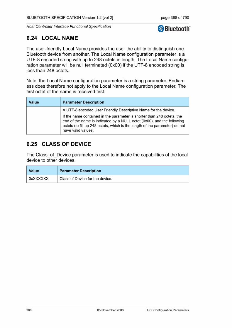
BLUETOOTH SPECIFICATION Version 1.2 [vol 2] page 368 of 790
Host Controller Interface Functional Specification
6.24 LOCAL NAME
The user-friendly Local Name provides the user the ability to distinguish one Bluetooth device from another. The Local Name configuration parameter is a UTF-8 encoded string with up to 248 octets in length. The Local Name configu-ration parameter will be null terminated (0x00) if the UTF-8 encoded string is less than 248 octets.
Note: the Local Name configuration parameter is a string parameter. Endian-ess does therefore not apply to the Local Name configuration parameter. The first octet of the name is received first.
6.25 CLASS OF DEVICE
The Class_of_Device parameter is used to indicate the capabilities of the local device to other devices.
Value Parameter Description
A UTF-8 encoded User Friendly Descriptive Name for the device.If the name contained in the parameter is shorter than 248 octets, the end of the name is indicated by a NULL octet (0x00), and the following octets (to fill up 248 octets, which is the length of the parameter) do not have valid values.
Value Parameter Description
0xXXXXXX Class of Device for the device.
368 05 November 2003 HCI Configuration Parameters
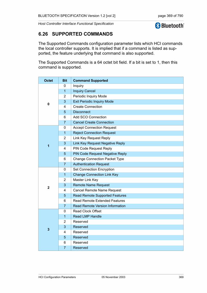
BLUETOOTH SPECIFICATION Version 1.2 [vol 2] page 369 of 790
Host Controller Interface Functional Specification
6.26 SUPPORTED COMMANDS
The Supported Commands configuration parameter lists which HCI commands the local controller supports. It is implied that if a command is listed as sup-ported, the feature underlying that command is also supported.
The Supported Commands is a 64 octet bit field. If a bit is set to 1, then this command is supported.
Octet Bit Command Supported
0
0 Inquiry1 Inquiry Cancel2 Periodic Inquiry Mode3 Exit Periodic Inquiry Mode4 Create Connection5 Disconnect6 Add SCO Connection7 Cancel Create Connection
1
0 Accept Connection Request1 Reject Connection Request2 Link Key Request Reply3 Link Key Request Negative Reply4 PIN Code Request Reply5 PIN Code Request Negative Reply6 Change Connection Packet Type7 Authentication Request
2
0 Set Connection Encryption1 Change Connection Link Key2 Master Link Key3 Remote Name Request4 Cancel Remote Name Request5 Read Remote Supported Features6 Read Remote Extended Features7 Read Remote Version Information
3
0 Read Clock Offset1 Read LMP Handle2 Reserved3 Reserved4 Reserved5 Reserved6 Reserved7 Reserved
HCI Configuration Parameters 05 November 2003 369
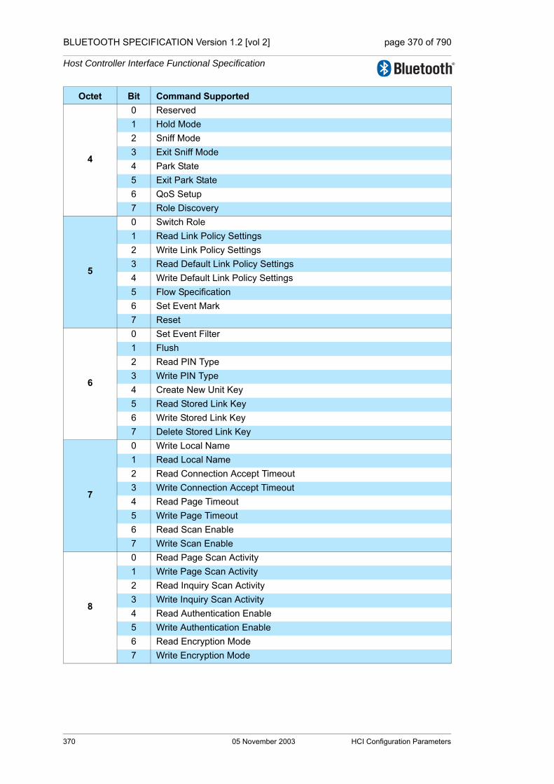
BLUETOOTH SPECIFICATION Version 1.2 [vol 2] page 370 of 790
Host Controller Interface Functional Specification
4
0 Reserved1 Hold Mode2 Sniff Mode3 Exit Sniff Mode4 Park State5 Exit Park State6 QoS Setup7 Role Discovery
5
0 Switch Role1 Read Link Policy Settings2 Write Link Policy Settings3 Read Default Link Policy Settings4 Write Default Link Policy Settings5 Flow Specification6 Set Event Mark7 Reset
6
0 Set Event Filter1 Flush2 Read PIN Type3 Write PIN Type4 Create New Unit Key5 Read Stored Link Key6 Write Stored Link Key7 Delete Stored Link Key
7
0 Write Local Name1 Read Local Name2 Read Connection Accept Timeout3 Write Connection Accept Timeout4 Read Page Timeout5 Write Page Timeout6 Read Scan Enable7 Write Scan Enable
8
0 Read Page Scan Activity1 Write Page Scan Activity2 Read Inquiry Scan Activity3 Write Inquiry Scan Activity4 Read Authentication Enable5 Write Authentication Enable6 Read Encryption Mode7 Write Encryption Mode
Octet Bit Command Supported
370 05 November 2003 HCI Configuration Parameters

BLUETOOTH SPECIFICATION Version 1.2 [vol 2] page 371 of 790
Host Controller Interface Functional Specification
9
0 Read Class Of Device1 Write Class Of Device2 Read Voice Setting3 Write Voice Setting4 Read Automatic Flush Timeout5 Write Automatic Flush Timeout6 Read Num Broadcast Retransmissions7 Write Num Broadcast Retransmissions
10
0 Read Hold Mode Activity1 Write Hold Mode Activity2 Read Transmit Power Level3 Read Synchronous Flow Control Enable4 Write Synchronous Flow Control Enable5 Set Host Controller To Host Flow Control6 Host Buffer Size7 Host Number Of Completed Packets
11
0 Read Link Supervision Timeout1 Write Link Supervision Timeout2 Read Number of Supported IAC3 Read Current IAC LAP4 Write Current IAC LAP5 Read Page Scan Period Mode6 Write Page Scan Period Mode7 Read Page Scan Mode
12
0 Write Page Scan Mode1 Set AFH Channel Classification2 reserved 3 reserved 4 Read Inquiry Scan Type5 Write Inquiry Scan Type6 Read Inquiry Mode7 Write Inquiry Mode
13
0 Read Page Scan Type1 Write Page Scan Type2 Read AFH Channel Assessment Mode3 Write AFH Channel Assessment Mode4 Reserved5 Reserved6 Reserved7 Reserved
Octet Bit Command Supported
HCI Configuration Parameters 05 November 2003 371

BLUETOOTH SPECIFICATION Version 1.2 [vol 2] page 372 of 790
Host Controller Interface Functional Specification
14
0 Reserved1 Reserved2 Reserved3 Read Local Version Information4 Reserved5 Read Local Supported Features6 Read Local Extended Features7 Read Buffer Size
15
0 Read Country Code1 Read BD ADDR2 Read Failed Contact Count3 Reset Failed Contact Count4 Get Link Quality5 Read RSSI6 Read AFH Channel Map7 Read BD Clock
16
0 Read Loopback Mode1 Write Loopback Mode2 Enable Device Under Test Mode3 Setup Synchronous Connection 4 Accept Synchronous Connection 5 Reject Synchronous Connection[6 Reserved7 Reserved
Octet Bit Command Supported
372 05 November 2003 HCI Configuration Parameters

BLUETOOTH SPECIFICATION Version 1.2 [vol 2] page 373 of 790
Host Controller Interface Functional Specification
7 HCI COMMANDS AND EVENTS
7.1 LINK CONTROL COMMANDS
The Link Control commands allow the Controller to control connections to other Bluetooth devices. When the Link Control commands are used, the Link Man-ager (LM) controls how the Bluetooth piconets and scatternets are established and maintained. These commands instruct the LM to create and modify link layer connections with Bluetooth remote devices, perform Inquiries of other Bluetooth devices in range, and other LMP commands. For the Link Control commands, the OGF is defined as 0x01.
7.1.1 Inquiry Command
Description:
This command will cause the Bluetooth device to enter Inquiry Mode. Inquiry Mode is used to discover other nearby Bluetooth devices. The LAP input parameter contains the LAP from which the inquiry access code shall be derived when the inquiry procedure is made. The Inquiry_Length parameter specifies the total duration of the Inquiry Mode and, when this time expires, Inquiry will be halted. The Num_Responses parameter specifies the number of responses that can be received before the Inquiry is halted. A Command Sta-tus event is sent from the Controller to the Host when the Inquiry command has been started by the Bluetooth device. When the Inquiry process is completed, the Controller will send an Inquiry Complete event to the Host indicating that the Inquiry has finished. The event parameters of Inquiry Complete event will have a summary of the result from the Inquiry process, which reports the num-ber of nearby Bluetooth devices that responded. When a Bluetooth device responds to the Inquiry message, an Inquiry Result event will occur to notify the Host of the discovery.
A device which responds during an inquiry or inquiry period should always be reported to the Host in an Inquiry Result event if the device has not been reported earlier during the current inquiry or inquiry period and the device has not been filtered out using the command Set_Event_Filter. If the device has been reported earlier during the current inquiry or inquiry period, it may or may not be reported depending on the implementation (depending on if earlier results have been saved in the Controller and in that case how many responses that have been saved). It is recommended that the Controller tries to report a particular device only once during an inquiry or inquiry period.
Command OCF Command Parameters Return Parameters
HCI_Inquiry 0x0001 LAP, Inquiry_Length,Num_Responses
HCI Commands and Events 05 November 2003 373

BLUETOOTH SPECIFICATION Version 1.2 [vol 2] page 374 of 790
Host Controller Interface Functional Specification
Command Parameters:
LAP: Size: 3 Octets
Inquiry_Length: Size: 1 Octet
Num_Responses: Size: 1 Octet
Return Parameters:
None.
Event(s) generated (unless masked away):
A Command Status event is sent from the Controller to the Host when the Con-troller has started the Inquiry process. An Inquiry Result event will be created for each Bluetooth device which responds to the Inquiry message. In addition, multiple Bluetooth devices which respond to the Inquire message may be com-bined into the same event. An Inquiry Complete event is generated when the Inquiry process has completed. Note: no Command Complete event will be sent by the Controller to indicate that this command has been completed. Instead, the Inquiry Complete event will indicate that this command has been completed. No Inquiry Com-plete event will be generated for the canceled Inquiry process.
Value Parameter Description
0x9E8B00–0X9E8B3F
This is the LAP from which the inquiry access code should be derived when the inquiry procedure is made; see “Bluetooth Assigned Numbers” (https://www.bluetooth.org/foundry/assignnumb/document/assigned_numbers).
Value Parameter Description
N = 0xXX Maximum amount of time specified before the Inquiry is halted.Size: 1 octetRange: 0x01 – 0x30Time = N * 1.28 secRange: 1.28 – 61.44 Sec
Value Parameter Description
0x00 Unlimited number of responses.
0xXX Maximum number of responses from the Inquiry before the Inquiry is halted.Range: 0x01 – 0xFF
374 05 November 2003 HCI Commands and Events
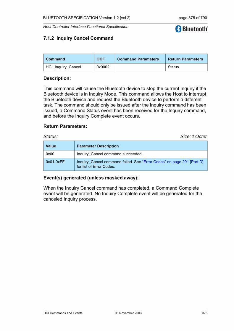
BLUETOOTH SPECIFICATION Version 1.2 [vol 2] page 375 of 790
Host Controller Interface Functional Specification
7.1.2 Inquiry Cancel Command
Description:
This command will cause the Bluetooth device to stop the current Inquiry if the Bluetooth device is in Inquiry Mode. This command allows the Host to interrupt the Bluetooth device and request the Bluetooth device to perform a different task. The command should only be issued after the Inquiry command has been issued, a Command Status event has been received for the Inquiry command, and before the Inquiry Complete event occurs.
Return Parameters:
Status: Size: 1 Octet
Event(s) generated (unless masked away):
When the Inquiry Cancel command has completed, a Command Complete event will be generated. No Inquiry Complete event will be generated for the canceled Inquiry process.
Command OCF Command Parameters Return Parameters
HCI_Inquiry_Cancel 0x0002 Status
Value Parameter Description
0x00 Inquiry_Cancel command succeeded.
0x01-0xFF Inquiry_Cancel command failed. See “Error Codes” on page 291 [Part D] for list of Error Codes.
HCI Commands and Events 05 November 2003 375

BLUETOOTH SPECIFICATION Version 1.2 [vol 2] page 376 of 790
Host Controller Interface Functional Specification
7.1.3 Periodic Inquiry Mode Command
Description:
The Periodic_Inquiry_Mode command is used to configure the Bluetooth device to enter the Periodic Inquiry Mode that performs an automatic Inquiry. Max_Period_Length and Min_Period_Length define the time range between two consecutive inquiries, from the beginning of an inquiry until the start of the next inquiry. The Controller will use this range to determine a new random time between two consecutive inquiries for each Inquiry. The LAP input parameter contains the LAP from which the inquiry access code shall be derived when the inquiry procedure is made. The Inquiry_Length parameter specifies the total duration of the InquiryMode and, when time expires, Inquiry will be halted. The Num_Responses parameter specifies the number of responses that can be received before the Inquiry is halted. This command is completed when the Inquiry process has been started by the Bluetooth device, and a Command Complete event is sent from the Controller to the Host. When each of the peri-odic Inquiry processes are completed, the Controller will send an Inquiry Com-plete event to the Host indicating that the latest periodic Inquiry process has finished. When a Bluetooth device responds to the Inquiry message an Inquiry Result event will occur to notify the Host of the discovery. Note: Max_Period_Length > Min_Period_Length > Inquiry_Length
A device which responds during an inquiry or inquiry period should always be reported to the Host in an Inquiry Result event if the device has not been reported earlier during the current inquiry or inquiry period and the device has not been filtered out using the command Set_Event_Filter. If the device has been reported earlier during the current inquiry or inquiry period, it may or may not be reported depending on the implementation (depending on if earlier results have been saved in the Controller and in that case how many responses that have been saved). It is recommended that the Controller tries to report a particular device only once during an inquiry or inquiry period.
Command OCF Command Parameters Return Parameters
HCI_Periodic_Inquiry_Mode
0x0003 Max_Period_Length,Min_Period_Length,LAP,Inquiry_Length,Num_Responses
Status
376 05 November 2003 HCI Commands and Events
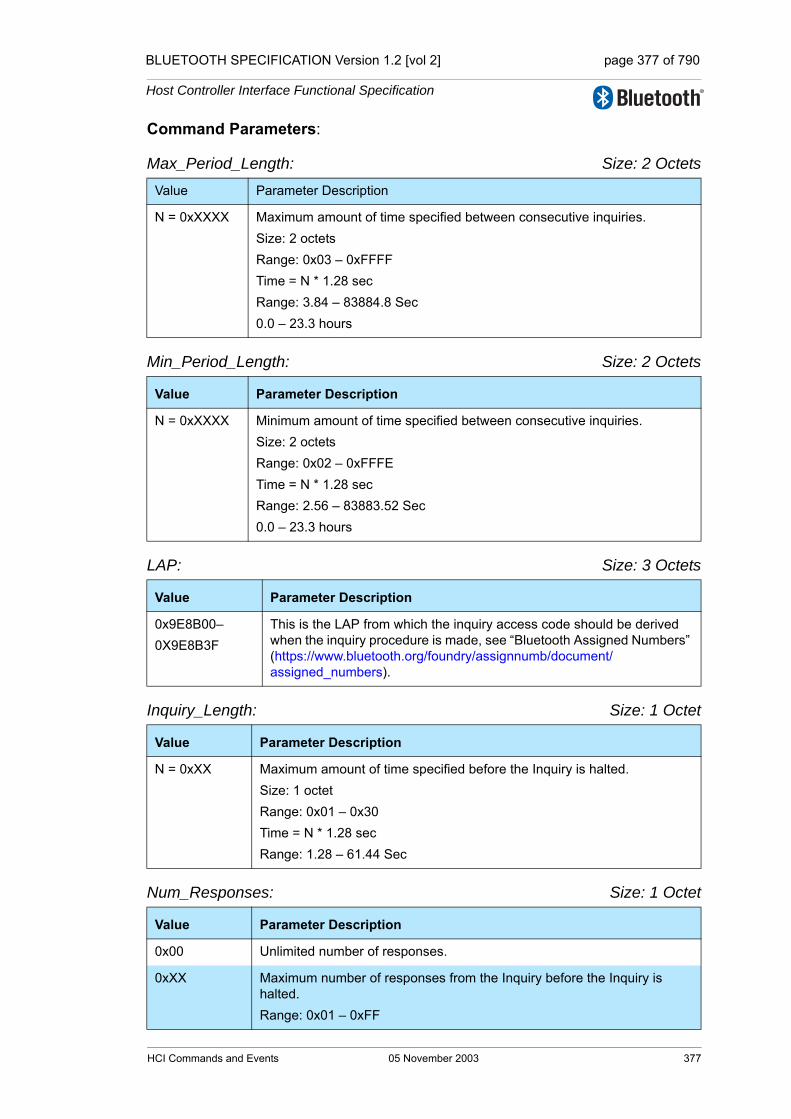
BLUETOOTH SPECIFICATION Version 1.2 [vol 2] page 377 of 790
Host Controller Interface Functional Specification
Command Parameters:
Max_Period_Length: Size: 2 Octets
Min_Period_Length: Size: 2 Octets
LAP: Size: 3 Octets
Inquiry_Length: Size: 1 Octet
Num_Responses: Size: 1 Octet
Value Parameter Description
N = 0xXXXX Maximum amount of time specified between consecutive inquiries.Size: 2 octetsRange: 0x03 – 0xFFFFTime = N * 1.28 secRange: 3.84 – 83884.8 Sec0.0 – 23.3 hours
Value Parameter Description
N = 0xXXXX Minimum amount of time specified between consecutive inquiries.Size: 2 octetsRange: 0x02 – 0xFFFETime = N * 1.28 secRange: 2.56 – 83883.52 Sec0.0 – 23.3 hours
Value Parameter Description
0x9E8B00–0X9E8B3F
This is the LAP from which the inquiry access code should be derived when the inquiry procedure is made, see “Bluetooth Assigned Numbers” (https://www.bluetooth.org/foundry/assignnumb/document/assigned_numbers).
Value Parameter Description
N = 0xXX Maximum amount of time specified before the Inquiry is halted.Size: 1 octetRange: 0x01 – 0x30Time = N * 1.28 secRange: 1.28 – 61.44 Sec
Value Parameter Description
0x00 Unlimited number of responses.
0xXX Maximum number of responses from the Inquiry before the Inquiry is halted.Range: 0x01 – 0xFF
HCI Commands and Events 05 November 2003 377

BLUETOOTH SPECIFICATION Version 1.2 [vol 2] page 378 of 790
Host Controller Interface Functional Specification
Return Parameters:
Status: Size: 1 Octet
Event(s) generated (unless masked away):
The Periodic Inquiry Mode begins when the Controller sends the Command Complete event for this command to the Host. An Inquiry Result event will be created for each Bluetooth device which responds to the Inquiry message. In addition, multiple Bluetooth devices which response to the Inquiry message may be combined into the same event. An Inquiry Complete event is generated when each of the periodic Inquiry processes has completed. No Inquiry Com-plete event will be generated for the canceled Inquiry process.
Value Parameter Description
0x00 Periodic Inquiry Mode command succeeded.
0x01-0xFF Periodic Inquiry Mode command failed. See “Error Codes” on page 291 [Part D] for list of Error Codes.
378 05 November 2003 HCI Commands and Events

BLUETOOTH SPECIFICATION Version 1.2 [vol 2] page 379 of 790
Host Controller Interface Functional Specification
7.1.4 Exit Periodic Inquiry Mode Command
Description:
The Exit Periodic Inquiry Mode command is used to end the Periodic Inquiry mode when the local device is in Periodic Inquiry Mode. If the local device is currently in an Inquiry process, the Inquiry process will be stopped directly and the Controller will no longer perform periodic inquiries until the Periodic Inquiry Mode command is reissued.
Command Parameters:
None.
Return Parameters:
Status: Size: 1 Octet
Event(s) generated (unless masked away):
A Command Complete event for this command will occur when the local device is no longer in Periodic Inquiry Mode. No Inquiry Complete event will be gener-ated for the canceled Inquiry process.
Command OCF Command Parameters Return Parameters
HCI_Exit_Periodic_Inquiry_Mode 0x0004 Status
Value Parameter Description
0x00 Exit Periodic Inquiry Mode command succeeded.
0x01-0xFF Exit Periodic Inquiry Mode command failed. See “Error Codes” on page 291 [Part D] for list of Error Codes.
HCI Commands and Events 05 November 2003 379
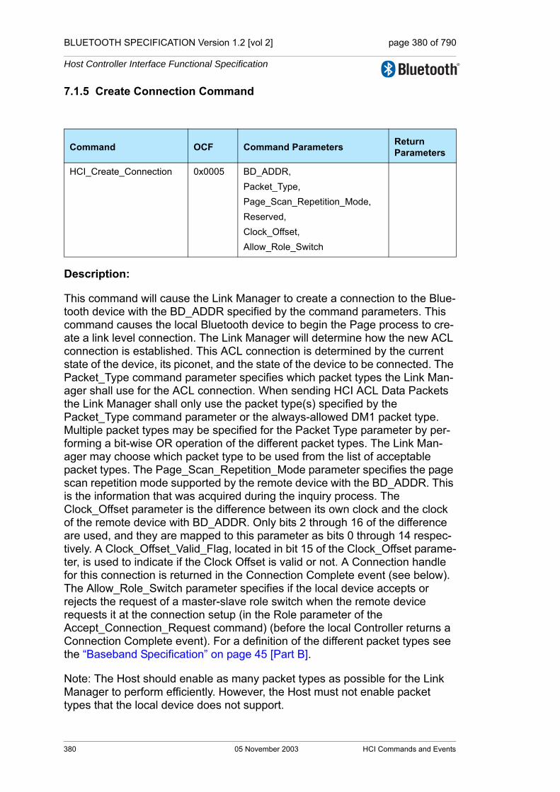
BLUETOOTH SPECIFICATION Version 1.2 [vol 2] page 380 of 790
Host Controller Interface Functional Specification
7.1.5 Create Connection Command
Description:
This command will cause the Link Manager to create a connection to the Blue-tooth device with the BD_ADDR specified by the command parameters. This command causes the local Bluetooth device to begin the Page process to cre-ate a link level connection. The Link Manager will determine how the new ACL connection is established. This ACL connection is determined by the current state of the device, its piconet, and the state of the device to be connected. The Packet_Type command parameter specifies which packet types the Link Man-ager shall use for the ACL connection. When sending HCI ACL Data Packets the Link Manager shall only use the packet type(s) specified by the Packet_Type command parameter or the always-allowed DM1 packet type. Multiple packet types may be specified for the Packet Type parameter by per-forming a bit-wise OR operation of the different packet types. The Link Man-ager may choose which packet type to be used from the list of acceptable packet types. The Page_Scan_Repetition_Mode parameter specifies the page scan repetition mode supported by the remote device with the BD_ADDR. This is the information that was acquired during the inquiry process. The Clock_Offset parameter is the difference between its own clock and the clock of the remote device with BD_ADDR. Only bits 2 through 16 of the difference are used, and they are mapped to this parameter as bits 0 through 14 respec-tively. A Clock_Offset_Valid_Flag, located in bit 15 of the Clock_Offset parame-ter, is used to indicate if the Clock Offset is valid or not. A Connection handle for this connection is returned in the Connection Complete event (see below). The Allow_Role_Switch parameter specifies if the local device accepts or rejects the request of a master-slave role switch when the remote device requests it at the connection setup (in the Role parameter of the Accept_Connection_Request command) (before the local Controller returns a Connection Complete event). For a definition of the different packet types see the “Baseband Specification” on page 45 [Part B].
Note: The Host should enable as many packet types as possible for the Link Manager to perform efficiently. However, the Host must not enable packet types that the local device does not support.
Command OCF Command Parameters Return Parameters
HCI_Create_Connection 0x0005 BD_ADDR,Packet_Type,Page_Scan_Repetition_Mode,Reserved,Clock_Offset,Allow_Role_Switch
380 05 November 2003 HCI Commands and Events
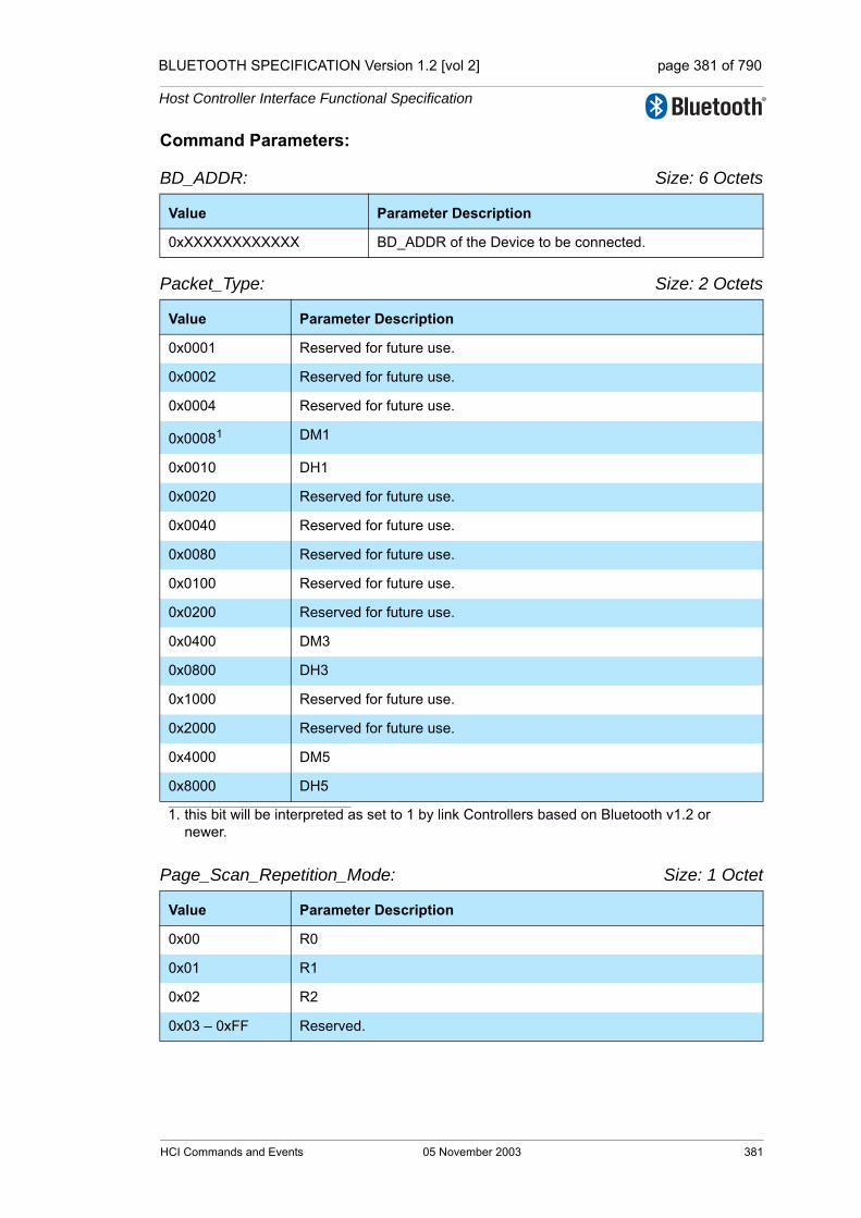
BLUETOOTH SPECIFICATION Version 1.2 [vol 2] page 381 of 790
Host Controller Interface Functional Specification
Command Parameters:
BD_ADDR: Size: 6 Octets
Packet_Type: Size: 2 Octets
Page_Scan_Repetition_Mode: Size: 1 Octet
Value Parameter Description
0xXXXXXXXXXXXX BD_ADDR of the Device to be connected.
Value Parameter Description
0x0001 Reserved for future use.
0x0002 Reserved for future use.
0x0004 Reserved for future use.
0x00081
1. this bit will be interpreted as set to 1 by link Controllers based on Bluetooth v1.2 or newer.
DM1
0x0010 DH1
0x0020 Reserved for future use.
0x0040 Reserved for future use.
0x0080 Reserved for future use.
0x0100 Reserved for future use.
0x0200 Reserved for future use.
0x0400 DM3
0x0800 DH3
0x1000 Reserved for future use.
0x2000 Reserved for future use.
0x4000 DM5
0x8000 DH5
Value Parameter Description
0x00 R0
0x01 R1
0x02 R2
0x03 – 0xFF Reserved.
HCI Commands and Events 05 November 2003 381

BLUETOOTH SPECIFICATION Version 1.2 [vol 2] page 382 of 790
Host Controller Interface Functional Specification
Reserved: Size: 1 Octet
Clock_Offset: Size: 2 Octets
Allow_Role_Switch: Size: 1 Octet
Return Parameters:
None.
Event(s) generated (unless masked away):
When the Controller receives the Create Connection command, the Controller sends the Command Status event to the Host. In addition, when the LM deter-mines the connection is established, the Controller, on both Bluetooth devices that form the connection, will send a Connection Complete event to each Host. The Connection Complete event contains the Connection Handle if this com-mand is successful. Note: no Command Complete event will be sent by the Controller to indicate that this command has been completed. Instead, the Connection Complete event will indicate that this command has been completed.
Value Parameter Description
0x00 Reserved, must be set to 0x00. See “Page Scan Mode” on page 586.
Bit format Parameter Description
Bit 14-0 Bit 16-2 of CLKslave-CLKmaster.
Bit 15 Clock_Offset_Valid_FlagInvalid Clock Offfset = 0Valid Clock Offset = 1
Value Parameter Description
0x00 The local device will be a master, and will not accept a role switch requested by the remote device at the connection setup.
0x01 The local device may be a master, or may become a slave after accepting a role switch requested by the remote device at the connec-tion setup.
0x02-0xFF Reserved for future use.
382 05 November 2003 HCI Commands and Events

BLUETOOTH SPECIFICATION Version 1.2 [vol 2] page 383 of 790
Host Controller Interface Functional Specification
7.1.6 Disconnect Command
Description:
The Disconnection command is used to terminate an existing connection. The Connection_Handle command parameter indicates which connection is to be disconnected. The Reason command parameter indicates the reason for end-ing the connection. The remote Bluetooth device will receive the Reason com-mand parameter in the Disconnection Complete event. All synchronous connections on a physical link should be disconnected before the ACL connec-tion on the same physical connection is disconnected.
Command Parameters:
Connection_Handle: Size: 2 Octets (12 Bits meaningful)
Reason: Size: 1 Octet
Return Parameters:
None.
Event(s) generated (unless masked away):
When the Controller receives the Disconnect command, it sends the Command Status event to the Host. The Disconnection Complete event will occur at each Host when the termination of the connection has completed, and indicates that this command has been completed. Note: No Command Complete event will be sent by the Controller to indicate that this command has been completed. Instead, the Disconnection Complete event will indicate that this command has been completed.
Command OCF Command Parameters Return Parameters
HCI_Disconnect 0x0006 Connection_Handle,Reason
Value Parameter Description
0xXXXX Connection Handle for the connection being disconnected.Range: 0x0000-0x0EFF (0x0F00 - 0x0FFF Reserved for future use)
Value Parameter Description
0x05, 0x13-0x15, 0x1A, 0x29
Authentication Failure error code (0x05), Other End Terminated Connec-tion error codes (0x13-0x15), Unsupported Remote Feature error code (0x1A) and Pairing with Unit Key Not Supported error code (0x29), see “Error Codes” on page 291 [Part D] for list of Error Codes.
HCI Commands and Events 05 November 2003 383
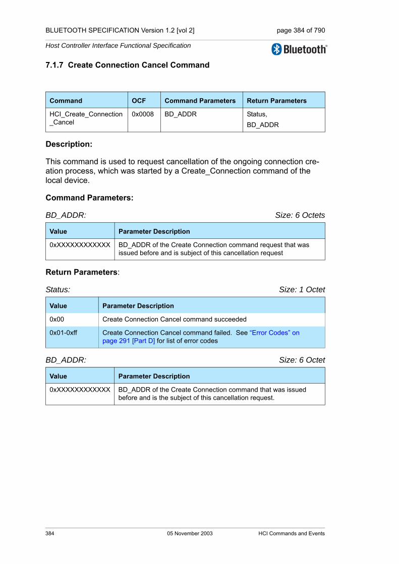
BLUETOOTH SPECIFICATION Version 1.2 [vol 2] page 384 of 790
Host Controller Interface Functional Specification
7.1.7 Create Connection Cancel Command
Description:
This command is used to request cancellation of the ongoing connection cre-ation process, which was started by a Create_Connection command of the local device.
Command Parameters:
BD_ADDR: Size: 6 Octets
Return Parameters:
Status: Size: 1 Octet
BD_ADDR: Size: 6 Octet
Command OCF Command Parameters Return Parameters
HCI_Create_Connection_Cancel
0x0008 BD_ADDR Status,BD_ADDR
Value Parameter Description
0xXXXXXXXXXXXX BD_ADDR of the Create Connection command request that was issued before and is subject of this cancellation request
Value Parameter Description
0x00 Create Connection Cancel command succeeded
0x01-0xff Create Connection Cancel command failed. See “Error Codes” on page 291 [Part D] for list of error codes
Value Parameter Description
0xXXXXXXXXXXXX BD_ADDR of the Create Connection command that was issued before and is the subject of this cancellation request.
384 05 November 2003 HCI Commands and Events
BLUETOOTH SPECIFICATION Version 1.2 [vol 2] page 385 of 790
Host Controller Interface Functional Specification
Event(s) generated (unless masked away):
When the Create Connection Cancel command has completed, a Command Complete event shall be generated.
If the connection is already established by the baseband, but the Controller has not yet sent the Connection Complete event, then the local device shall detach the link and return a Command Complete event with the status “Success”.
If the connection is already established, and the Connection Complete event has been sent, then the Controller shall return a Command Complete event with the error code ACL Connection already exists (0x0B).
If the Create Connection Cancel command is sent to the Controller without a preceding Create Connection command to the same device, the Controller shall return a Command Complete event with the error code Unknown Connec-tion Identifier (0x02).
The error codes Unspecified Error (0x1F) and Command Disallowed (0x0C) may be used if the Controller does not support this command.
The Connection Complete event for the corresponding Create Connection Command shall always be sent. The Connection Complete event shall be sent after the Command Complete event for the Create Connection Cancel com-mand. If the cancellation was successful, the Connection Complete event will be generated with the error code Unknown Connection Identifier (0x02).
HCI Commands and Events 05 November 2003 385

BLUETOOTH SPECIFICATION Version 1.2 [vol 2] page 386 of 790
Host Controller Interface Functional Specification
7.1.8 Accept Connection Request Command
Description:
The Accept_Connection_Request command is used to accept a new incoming connection request. The Accept_Connection_Request command shall only be issued after a Connection Request event has occurred. The Connection Request event will return the BD_ADDR of the device which is requesting the connection. This command will cause the Link Manager to create a connection to the Bluetooth device, with the BD_ADDR specified by the command param-eters. The Link Manager will determine how the new connection will be estab-lished. This will be determined by the current state of the device, its piconet, and the state of the device to be connected. The Role command parameter allows the Host to specify if the Link Manager shall request a role switch and become the Master for this connection. This is a preference and not a require-ment. If the Role Switch fails then the connection will still be accepted, and the Role Discovery Command will reflect the current role. Note: The Link Manager may terminate the connection if it would be low on resources if the role switch fails. The decision to accept a connection must be completed before the connection accept timeout expires on the local Bluetooth Module.Note: when accepting synchronous connection request, the Role parameter is not used and will be ignored by the Controller.
Command Parameters:
BD_ADDR: Size: 6 Octets
Role: Size: 1 Octet
Return Parameters:
None.
Command OCF Command Parameters Return Parameters
HCI_Accept_ConnectionRequest
0x0009 BD_ADDR, Role
Value Parameter Description
0xXXXXXXXXXXXX BD_ADDR of the Device to be connected
Value Parameter Description
0x00 Become the Master for this connection. The LM will perform the role switch.
0x01 Remain the Slave for this connection. The LM will NOT perform the role switch.
386 05 November 2003 HCI Commands and Events

BLUETOOTH SPECIFICATION Version 1.2 [vol 2] page 387 of 790
Host Controller Interface Functional Specification
Event(s) generated (unless masked away):
The Accept_Connection_Request command will cause the Command Status event to be sent from the Controller when the Controller begins setting up the connection. In addition, when the Link Manager determines the connection is established,the local Controller will send a Connection Complete event to its Host, and the remote Controller will send a Connection Complete event or a Synchronous Connection Complete event to the Host. The Connection Com-plete event contains the Connection Handle if this command is successful. Note: no Command Complete event will be sent by the Controller to indicate that this command has been completed. Instead, the Connection Complete event will indicate that this command has been completed.
HCI Commands and Events 05 November 2003 387

BLUETOOTH SPECIFICATION Version 1.2 [vol 2] page 388 of 790
Host Controller Interface Functional Specification
7.1.9 Reject Connection Request Command
Description:
The Reject_Connection_Request command is used to decline a new incoming connection request. The Reject_Connection_Request command shall only be called after a Connection Request event has occurred. The Connection Request event will return the BD_ADDR of the device that is requesting the connection. The Reason command parameter will be returned to the connect-ing device in the Status parameter of the Connection Complete event returned to the Host of the connection device, to indicate why the connection was declined.
Command Parameters:
BD_ADDR: Size: 6 Octets
Reason: Size: 1 Octet
Return Parameters:
None.
Event(s) generated (unless masked away):
When the Controller receives the Reject_Connection_Request command, the Controller sends the Command Status event to the Host. Then, the local Con-troller will send a Connection Complete event to its host, and the remote Con-troller will send a Connection Complete event or a Synchronous Connection Complete event to the host. The Status parameter of the Connection Complete event, which is sent to the Host of the device attempting to make the connec-tion, will contain the Reason command parameter from this command. Note: no Command Complete event will be sent by the Controller to indicate that this command has been completed. Instead, the Connection Complete event will indicate that this command has been completed.
Command OCF Command Parameters Return Parameters
HCI_Reject_Connection_Request
0x000A BD_ADDR, Reason
Value Parameter Description
0xXXXXXXXXXXXX BD_ADDR of the Device to reject the connection from.
Value Parameter Description
0x0D-0x0F Host Reject Error Code. See “Error Codes” on page 291 [Part D] for list of Error Codes and descriptions.
388 05 November 2003 HCI Commands and Events

BLUETOOTH SPECIFICATION Version 1.2 [vol 2] page 389 of 790
Host Controller Interface Functional Specification
7.1.10 Link Key Request Reply Command
Description:
The Link_Key_Request_Reply command is used to reply to a Link Key Request event from the Controller, and specifies the Link Key stored on the Host to be used as the link key for the connection with the other Bluetooth Device specified by BD_ADDR. The Link Key Request event will be generated when the Controller needs a Link Key for a connection.
When the Controller generates a Link Key Request event in order for the local Link Manager to respond to the request from the remote Link Manager (as a result of a Create_Connection or Authentication_Requested command from the remote Host), the local Host must respond with either a Link_Key_Request_Reply or Link_Key_Request_Negative_Reply command before the remote Link Manager detects LMP response timeout. (See “Link Manager Protocol” on page 189 [Part C].)
Command Parameters:
BD_ADDR: Size: 6 Octets
Link_Key: Size: 16 Octets
Return Parameters:
Status: Size: 1 Octet
Command OCF Command Parameters Return Parameters
HCI_Link_Key_Request_Reply 0x000B BD_ADDR, Link_Key Status, BD_ADDR
Value Parameter Description
0xXXXXXXXXXXXX BD_ADDR of the Device of which the Link Key is for.
Value Parameter Description
0xXXXXXXXXXXXXXXXXXXXXXXXXXXXXXXXX
Link Key for the associated BD_ADDR.
Value Parameter Description
0x00 Link_Key_Request_Reply command succeeded.
0x01-0xFF Link_Key_Request_Reply command failed. See “Error Codes” on page 291 [Part D] for error codes and description.
HCI Commands and Events 05 November 2003 389
BLUETOOTH SPECIFICATION Version 1.2 [vol 2] page 390 of 790
Host Controller Interface Functional Specification
BD_ADDR: Size: 6 Octets
Event(s) generated (unless masked away):
The Link_Key_Request_Reply command will cause a Command Complete event to be generated.
Value Parameter Description
0xXXXXXXXXXXXX
BD_ADDR of the Device of which the Link Key request reply has completed.
390 05 November 2003 HCI Commands and Events
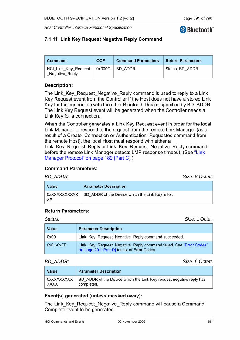
BLUETOOTH SPECIFICATION Version 1.2 [vol 2] page 391 of 790
Host Controller Interface Functional Specification
7.1.11 Link Key Request Negative Reply Command
Description: The Link_Key_Request_Negative_Reply command is used to reply to a Link Key Request event from the Controller if the Host does not have a stored Link Key for the connection with the other Bluetooth Device specified by BD_ADDR. The Link Key Request event will be generated when the Controller needs a Link Key for a connection.
When the Controller generates a Link Key Request event in order for the local Link Manager to respond to the request from the remote Link Manager (as a result of a Create_Connection or Authentication_Requested command from the remote Host), the local Host must respond with either a Link_Key_Request_Reply or Link_Key_Request_Negative_Reply command before the remote Link Manager detects LMP response timeout. (See “Link Manager Protocol” on page 189 [Part C].)
Command Parameters: BD_ADDR: Size: 6 Octets
Return Parameters:Status: Size: 1 Octet
BD_ADDR: Size: 6 Octets
Event(s) generated (unless masked away): The Link_Key_Request_Negative_Reply command will cause a Command Complete event to be generated.
Command OCF Command Parameters Return Parameters
HCI_Link_Key_Request_Negative_Reply
0x000C BD_ADDR Status, BD_ADDR
Value Parameter Description
0xXXXXXXXXXXXX
BD_ADDR of the Device which the Link Key is for.
Value Parameter Description
0x00 Link_Key_Request_Negative_Reply command succeeded.
0x01-0xFF Link_Key_Request_Negative_Reply command failed. See “Error Codes” on page 291 [Part D] for list of Error Codes.
Value Parameter Description
0xXXXXXXXXXXXX
BD_ADDR of the Device which the Link Key request negative reply has completed.
HCI Commands and Events 05 November 2003 391

BLUETOOTH SPECIFICATION Version 1.2 [vol 2] page 392 of 790
Host Controller Interface Functional Specification
7.1.12 PIN Code Request Reply Command
Description:
The PIN_Code_Request_Reply command is used to reply to a PIN Code request event from the Controller, and specifies the PIN code to use for a con-nection. The PIN Code Request event will be generated when a connection with remote initiating device has requested pairing.
When the Controller generates a PIN Code Request event in order for the local Link Manager to respond to the request from the remote Link Manager (as a result of a Create_Connection or Authentication_Requested command from the remote Host), the local Host must respond with either a PIN_Code_Request_Reply or PIN_Code_Request_Negative_Reply com-mand before the remote Link Manager detects LMP response timeout. (See “Link Manager Protocol” on page 189 [Part C].)
Command Parameters:
BD_ADDR: Size: 6 Octets
PIN_Code_Length: Size: 1 Octet
PIN_Code: Size: 16 Octets
Command OCF Command Parameters Return Parameters
HCI_PIN_Code_Request_Reply 0x000D BD_ADDR,PIN_Code_Length,PIN_Code
Status, BD_ADDR
Value Parameter Description
0xXXXXXXXXXXXX
BD_ADDR of the Device which the PIN code is for.
Value Parameter Description
0xXX The PIN code length specifics the length, in octets, of the PIN code to be used. Range: 0x01-0x10
Value Parameter Description
0xXXXXXXXXXXXXXXXXXXXXXXXXXXXXXXXX
PIN code for the device that is to be connected. The Host should insure that strong PIN Codes are used. PIN Codes can be up to a maximum of 128 bits. Note: the PIN_Code Parameter is a string parameter. Endian-ess does therefore not apply to the PIN_Code Parameter. The first octet of the PIN code should be transmitted first.
392 05 November 2003 HCI Commands and Events
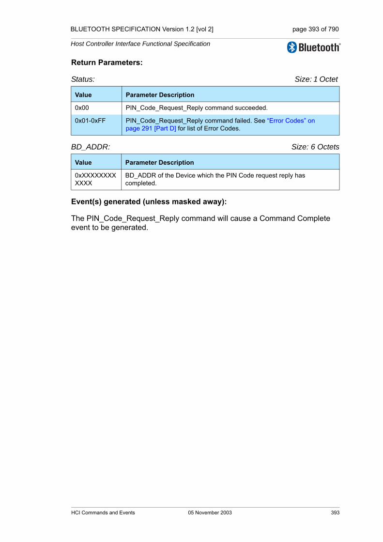
BLUETOOTH SPECIFICATION Version 1.2 [vol 2] page 393 of 790
Host Controller Interface Functional Specification
Return Parameters:
Status: Size: 1 Octet
BD_ADDR: Size: 6 Octets
Event(s) generated (unless masked away):
The PIN_Code_Request_Reply command will cause a Command Complete event to be generated.
Value Parameter Description
0x00 PIN_Code_Request_Reply command succeeded.
0x01-0xFF PIN_Code_Request_Reply command failed. See “Error Codes” on page 291 [Part D] for list of Error Codes.
Value Parameter Description
0xXXXXXXXXXXXX
BD_ADDR of the Device which the PIN Code request reply has completed.
HCI Commands and Events 05 November 2003 393

BLUETOOTH SPECIFICATION Version 1.2 [vol 2] page 394 of 790
Host Controller Interface Functional Specification
7.1.13 PIN Code Request Negative Reply Command
Description:
The PIN_Code_Request_Negative_Reply command is used to reply to a PIN Code request event from the Controller when the Host cannot specify a PIN code to use for a connection. This command will cause the pair request with remote device to fail.
When the Controller generates a PIN Code Request event in order for the local Link Manager to respond to the request from the remote Link Manager (as a result of a Create_Connection or Authentication_Requested command from the remote Host), the local Host must respond with either a PIN_Code_Request_Reply or PIN_Code_Request_Negative_Reply com-mand before the remote Link Manager detects LMP response timeout. (See “Link Manager Protocol” on page 189 [Part C].)
Command Parameters: BD_ADDR: Size: 6 Octets
Return Parameters:Status: Size: 1 Octet
BD_ADDR: Size: 6 Octets
Event(s) generated (unless masked away):
The PIN_Code_Request_Negative_Reply command will cause a Command Complete event to be generated.
Command OCF Command Parameters Return Parameters
HCI_PIN_Code_Request_Negative Reply
0x000E BD_ADDR Status, BD_ADDR
Value Parameter Description
0xXXXXXXXXXXXX BD_ADDR of the Device which this command is responding to.
Value Parameter Description
0x00 PIN_Code_Request_Negative_Reply command succeeded.
0x01-0xFF PIN_Code_Request_Negative_Reply command failed. See “Error Codes” on page 291 [Part D] for list of Error Codes.
Value Parameter Description
0xXXXXXXXXXXXX
BD_ADDR of the Device which the PIN Code request negative reply has completed.
394 05 November 2003 HCI Commands and Events

BLUETOOTH SPECIFICATION Version 1.2 [vol 2] page 395 of 790
Host Controller Interface Functional Specification
7.1.14 Change Connection Packet Type Command
Description:
The Change_Connection_Packet_Type command is used to change which packet types can be used for a connection that is currently established. This allows current connections to be dynamically modified to support different types of user data. The Packet_Type command parameter specifies which packet types the Link Manager can use for the connection. When sending HCI ACL Data Packets the Link Manager shall only use the packet type(s) specified by the Packet_Type command parameter or the always-allowed DM1 packet type. The interpretation of the value for the Packet_Type command parameter will depend on the Link_Type command parameter returned in the Connection Complete event at the connection setup. Multiple packet types may be speci-fied for the Packet_Type command parameter by bitwise OR operation of the different packet types. For a definition of the different packet types see the “Baseband Specification” on page 45 [Part B].
Note: The Host should enable as many packet types as possible for the Link Manager to perform efficiently. However, the Host must not enable packet types that the local device does not support.
Note: to change an eSCO connection, use the Setup Synchronous Connection command.
Command Parameters:
Connection_Handle: Size: 2 Octets (12 Bits meaningful)
Command OCF Command Parameters Return Parameters
HCI_Change_Connection_Packet_Type
0x000F Connection_Handle,Packet_Type
Value Parameter Description
0xXXXX Connection Handle to be used to for transmitting and receiving voice or data. Returned from creating a connection.Range: 0x0000-0x0EFF (0x0F00 - 0x0FFF Reserved for future use)
HCI Commands and Events 05 November 2003 395

BLUETOOTH SPECIFICATION Version 1.2 [vol 2] page 396 of 790
Host Controller Interface Functional Specification
Packet_Type: Size: 2 Octets
For ACL Link_Type
Value Parameter Description
0x0001 Reserved for future use.
0x0002 Reserved for future use.
0x0004 Reserved for future use.
0x00081
1. this bit will be interpreted as set to 1 by link Controllers based on Bluetooth v1.2 or newer.
DM1
0x0010 DH1
0x0020 Reserved for future use.
0x0040 Reserved for future use.
0x0080 Reserved for future use.
0x0100 Reserved for future use.
0x0200 Reserved for future use.
0x0400 DM3
0x0800 DH3
0x1000 Reserved for future use.
0x2000 Reserved for future use.
0x4000 DM5
0x8000 DH5
396 05 November 2003 HCI Commands and Events
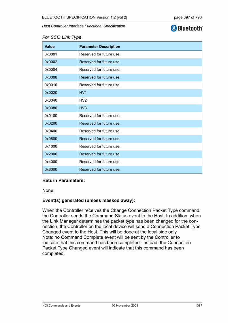
BLUETOOTH SPECIFICATION Version 1.2 [vol 2] page 397 of 790
Host Controller Interface Functional Specification
For SCO Link Type
Return Parameters:
None.
Event(s) generated (unless masked away):
When the Controller receives the Change Connection Packet Type command, the Controller sends the Command Status event to the Host. In addition, when the Link Manager determines the packet type has been changed for the con-nection, the Controller on the local device will send a Connection Packet Type Changed event to the Host. This will be done at the local side only. Note: no Command Complete event will be sent by the Controller to indicate that this command has been completed. Instead, the Connection Packet Type Changed event will indicate that this command has been completed.
Value Parameter Description
0x0001 Reserved for future use.
0x0002 Reserved for future use.
0x0004 Reserved for future use.
0x0008 Reserved for future use.
0x0010 Reserved for future use.
0x0020 HV1
0x0040 HV2
0x0080 HV3
0x0100 Reserved for future use.
0x0200 Reserved for future use.
0x0400 Reserved for future use.
0x0800 Reserved for future use.
0x1000 Reserved for future use.
0x2000 Reserved for future use.
0x4000 Reserved for future use.
0x8000 Reserved for future use.
HCI Commands and Events 05 November 2003 397

BLUETOOTH SPECIFICATION Version 1.2 [vol 2] page 398 of 790
Host Controller Interface Functional Specification
7.1.15 Authentication Requested Command
Description:
The Authentication_Requested command is used to try to authenticate the remote device associated with the specified Connection Handle. On an authen-tication failure, the Controller or Link Manager shall not automatically detach the link. The Host is responsible for issuing a Disconnect command to termi-nate the link if the action is appropriate.Note: the Connection_Handle command parameter is used to identify the other Bluetooth device, which forms the connection. The Connection Handle should be a Connection Handle for an ACL connection.
Command Parameters:
Connection_Handle: Size 2 Octets (12 Bits meaningful)
Return Parameters:
None.
Event(s) generated (unless masked away):
When the Controller receives the Authentication_Requested command, it sends the Command Status event to the Host. The Authentication Complete event will occur when the authentication has been completed for the connec-tion and is indication that this command has been completed. Note: no Command Complete event will be sent by the Controller to indicate that this command has been completed. Instead, the Authentication Complete event will indicate that this command has been completed.
Note: When the local or remote Controller does not have a link key for the specified Connection_Handle, it will request the link key from its Host, before the local Host finally receives the Authentication Complete event.
Command OCF Command Parameters Return Parameters
HCI_Authentication_Requested
0x0011 Connection_Handle
Value Parameter Description
0xXXXX Connection Handle to be used to set up authentication for all Connection Handles with the same Bluetooth device end-point as the specified Con-nection Handle.Range: 0x0000-0x0EFF (0x0F00 - 0x0FFF Reserved for future use)
398 05 November 2003 HCI Commands and Events
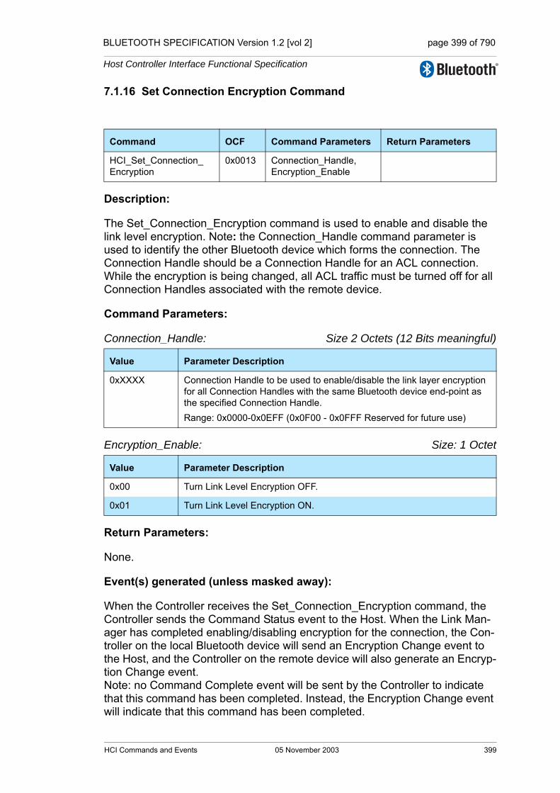
BLUETOOTH SPECIFICATION Version 1.2 [vol 2] page 399 of 790
Host Controller Interface Functional Specification
7.1.16 Set Connection Encryption Command
Description:
The Set_Connection_Encryption command is used to enable and disable the link level encryption. Note: the Connection_Handle command parameter is used to identify the other Bluetooth device which forms the connection. The Connection Handle should be a Connection Handle for an ACL connection. While the encryption is being changed, all ACL traffic must be turned off for all Connection Handles associated with the remote device.
Command Parameters:
Connection_Handle: Size 2 Octets (12 Bits meaningful)
Encryption_Enable: Size: 1 Octet
Return Parameters:
None.
Event(s) generated (unless masked away):
When the Controller receives the Set_Connection_Encryption command, the Controller sends the Command Status event to the Host. When the Link Man-ager has completed enabling/disabling encryption for the connection, the Con-troller on the local Bluetooth device will send an Encryption Change event to the Host, and the Controller on the remote device will also generate an Encryp-tion Change event. Note: no Command Complete event will be sent by the Controller to indicate that this command has been completed. Instead, the Encryption Change event will indicate that this command has been completed.
Command OCF Command Parameters Return Parameters
HCI_Set_Connection_Encryption
0x0013 Connection_Handle,Encryption_Enable
Value Parameter Description
0xXXXX Connection Handle to be used to enable/disable the link layer encryption for all Connection Handles with the same Bluetooth device end-point as the specified Connection Handle.Range: 0x0000-0x0EFF (0x0F00 - 0x0FFF Reserved for future use)
Value Parameter Description
0x00 Turn Link Level Encryption OFF.
0x01 Turn Link Level Encryption ON.
HCI Commands and Events 05 November 2003 399

BLUETOOTH SPECIFICATION Version 1.2 [vol 2] page 400 of 790
Host Controller Interface Functional Specification
7.1.17 Change Connection Link Key Command
Description:
The Change_Connection_Link_Key command is used to force both devices of a connection associated with the connection handle to generate a new link key. The link key is used for authentication and encryption of connections. Note: the Connection_Handle command parameter is used to identify the other Bluetooth device forming the connection. The Connection Handle should be a Connection Handle for an ACL connection.
Command Parameters:
Connection_Handle: Size 2 Octets (12 Bits meaningful)
Return Parameters:
None.
Event(s) generated (unless masked away):
When the Controller receives the Change_Connection_Link_Key command, the Controller sends the Command Status event to the Host. When the Link Manager has changed the Link Key for the connection, the Controller on the local Bluetooth device will send a Link Key Notification event and a Change Connection Link Key Complete event to the Host, and the Controller on the remote device will also generate a Link Key Notification event. The Link Key Notification event indicates that a new connection link key is valid for the con-nection. Note: no Command Complete event will be sent by the Controller to indicate that this command has been completed. Instead, the Change Connection Link Key Complete event will indicate that this command has been completed.
Command OCF Command Parameters Return Parameters
HCI_Change_Connection_Link_Key
0x0015 Connection_Handle
Value Parameter Description
0xXXXX Connection Handle used to identify a connection.Range: 0x0000-0x0EFF (0x0F00 - 0x0FFF Reserved for future use)
400 05 November 2003 HCI Commands and Events
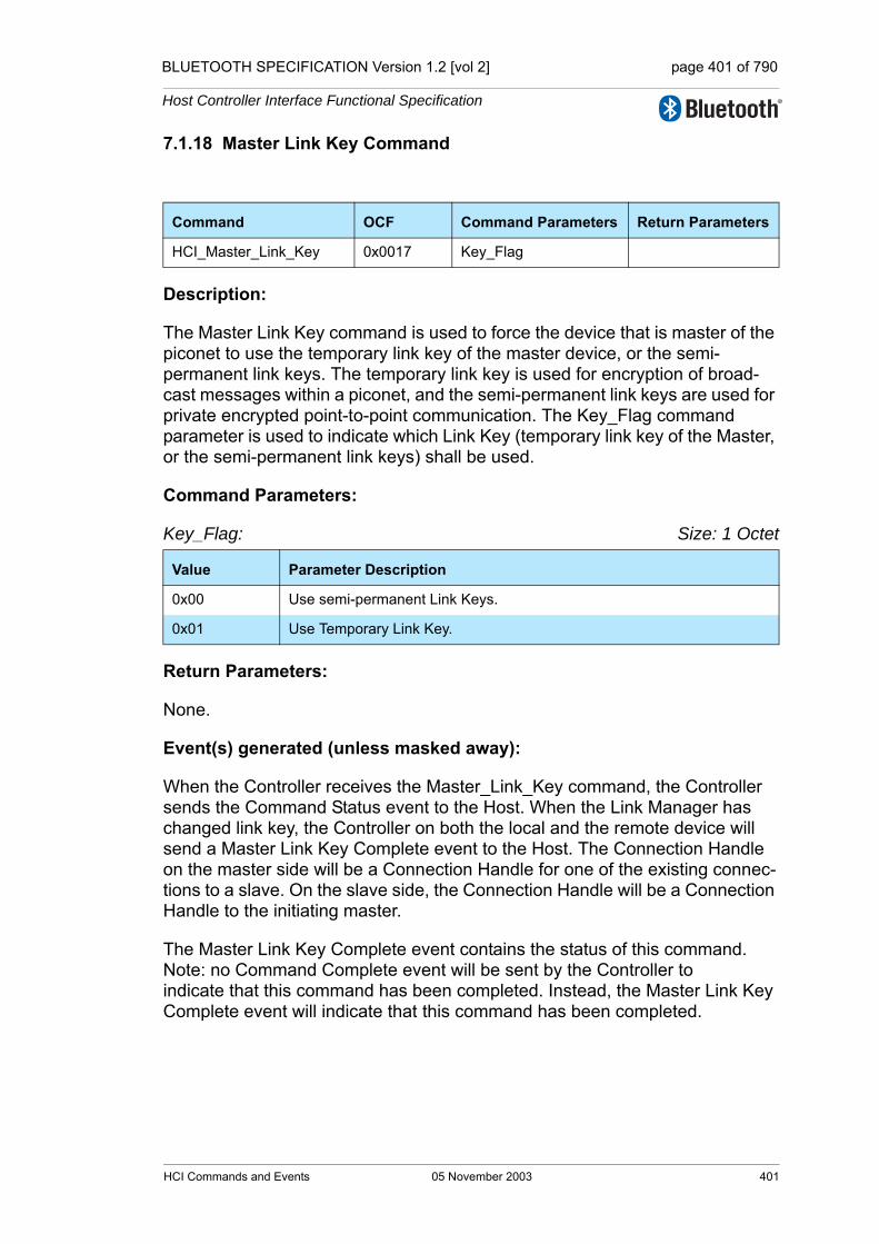
BLUETOOTH SPECIFICATION Version 1.2 [vol 2] page 401 of 790
Host Controller Interface Functional Specification
7.1.18 Master Link Key Command
Description:
The Master Link Key command is used to force the device that is master of the piconet to use the temporary link key of the master device, or the semi-permanent link keys. The temporary link key is used for encryption of broad-cast messages within a piconet, and the semi-permanent link keys are used for private encrypted point-to-point communication. The Key_Flag command parameter is used to indicate which Link Key (temporary link key of the Master, or the semi-permanent link keys) shall be used.
Command Parameters:
Key_Flag: Size: 1 Octet
Return Parameters:
None.
Event(s) generated (unless masked away):
When the Controller receives the Master_Link_Key command, the Controller sends the Command Status event to the Host. When the Link Manager has changed link key, the Controller on both the local and the remote device will send a Master Link Key Complete event to the Host. The Connection Handle on the master side will be a Connection Handle for one of the existing connec-tions to a slave. On the slave side, the Connection Handle will be a Connection Handle to the initiating master.
The Master Link Key Complete event contains the status of this command.Note: no Command Complete event will be sent by the Controller to indicate that this command has been completed. Instead, the Master Link Key Complete event will indicate that this command has been completed.
Command OCF Command Parameters Return Parameters
HCI_Master_Link_Key 0x0017 Key_Flag
Value Parameter Description
0x00 Use semi-permanent Link Keys.
0x01 Use Temporary Link Key.
HCI Commands and Events 05 November 2003 401
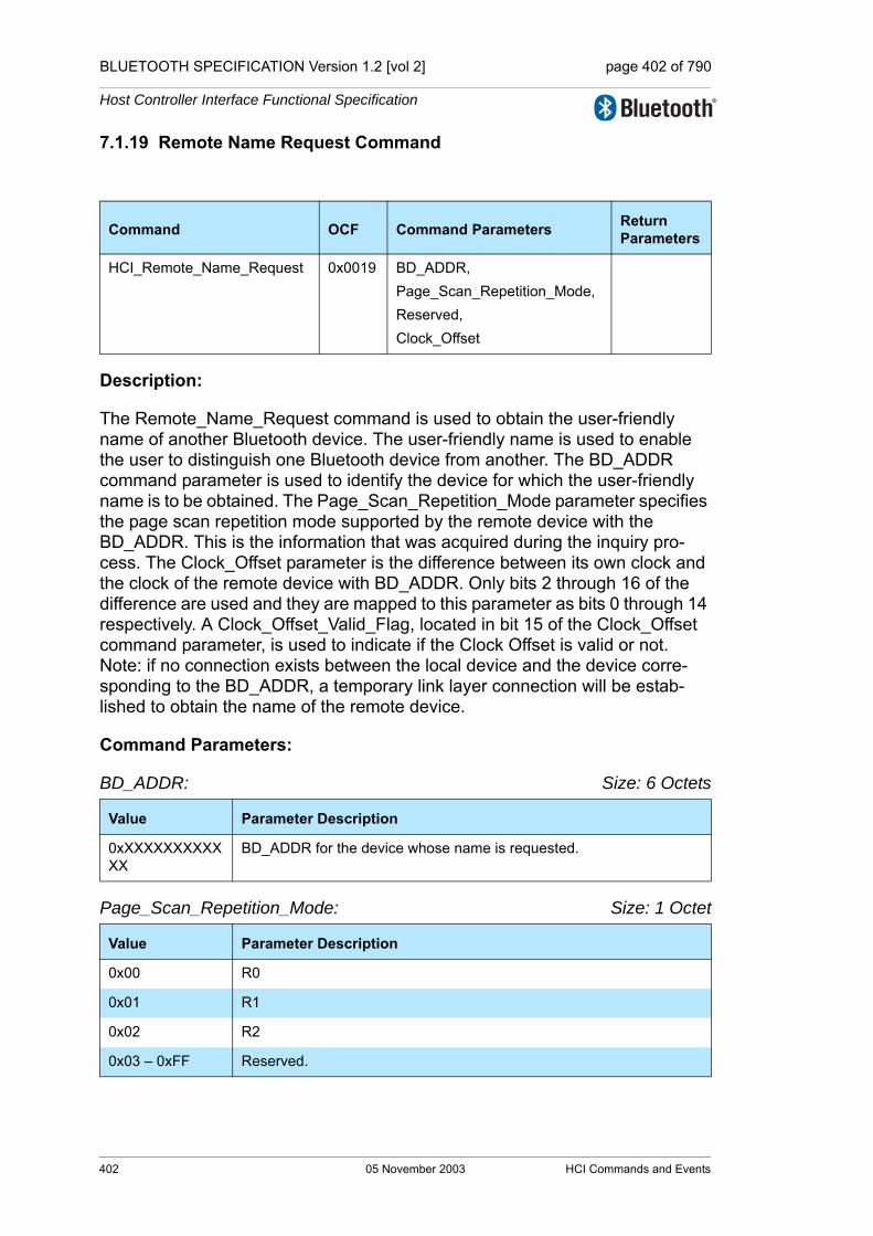
BLUETOOTH SPECIFICATION Version 1.2 [vol 2] page 402 of 790
Host Controller Interface Functional Specification
7.1.19 Remote Name Request Command
Description:
The Remote_Name_Request command is used to obtain the user-friendly name of another Bluetooth device. The user-friendly name is used to enable the user to distinguish one Bluetooth device from another. The BD_ADDR command parameter is used to identify the device for which the user-friendly name is to be obtained. The Page_Scan_Repetition_Mode parameter specifies the page scan repetition mode supported by the remote device with the BD_ADDR. This is the information that was acquired during the inquiry pro-cess. The Clock_Offset parameter is the difference between its own clock and the clock of the remote device with BD_ADDR. Only bits 2 through 16 of the difference are used and they are mapped to this parameter as bits 0 through 14 respectively. A Clock_Offset_Valid_Flag, located in bit 15 of the Clock_Offset command parameter, is used to indicate if the Clock Offset is valid or not. Note: if no connection exists between the local device and the device corre-sponding to the BD_ADDR, a temporary link layer connection will be estab-lished to obtain the name of the remote device.
Command Parameters:
BD_ADDR: Size: 6 Octets
Page_Scan_Repetition_Mode: Size: 1 Octet
Command OCF Command Parameters Return Parameters
HCI_Remote_Name_Request 0x0019 BD_ADDR,Page_Scan_Repetition_Mode,Reserved, Clock_Offset
Value Parameter Description
0xXXXXXXXXXXXX
BD_ADDR for the device whose name is requested.
Value Parameter Description
0x00 R0
0x01 R1
0x02 R2
0x03 – 0xFF Reserved.
402 05 November 2003 HCI Commands and Events

BLUETOOTH SPECIFICATION Version 1.2 [vol 2] page 403 of 790
Host Controller Interface Functional Specification
Reserved: Size: 1 Octet
Clock_Offset: Size: 2 Octets
Return Parameters:
None.
Event(s) generated (unless masked away):
When the Controller receives the Remote_Name_Request command, the Con-troller sends the Command Status event to the Host. When the Link Manager has completed the LMP messages to obtain the remote name, the Controller on the local Bluetooth device will send a Remote Name Request Complete event to the Host. Note: no Command Complete event will be sent by the Con-troller to indicate that this command has been completed. Instead, only the Remote Name Request Complete event will indicate that this command has been completed.
Value Parameter Description
0x00 Reserved, must be set to 0x00. See “Page Scan Mode” on page 586.
Bit format Parameter Description
Bit 14.0 Bit 16.2 of CLKslave-CLKmaster.
Bit 15 Clock_Offset_Valid_FlagInvalid Clock Offfset = 0Valid Clock Offset = 1
HCI Commands and Events 05 November 2003 403

BLUETOOTH SPECIFICATION Version 1.2 [vol 2] page 404 of 790
Host Controller Interface Functional Specification
7.1.20 Remote Name Request Cancel Command
Description:
This command is used to request cancellation of the ongoing remote name request process, which was started by the Remote Name Request command.
Command Parameters:
BD_ADDR: Size: 6 Octets
Return Parameters:
Status: Size: 1 Octet
BD_ADDR: Size: 6 Octets
Event(s) generated (unless masked away):
When the Remote Name Request Cancel command has completed, a Com-mand Complete event shall be generated.
If the Remote Name Request Cancel command is sent to the Controller without a preceding Remote Name Request command to the same device, the Con-troller will return a Command Complete event with the error code Invalid HCI Command Parameters (0x12).
The error codes Unspecified Error (0x1F) and Command Disallowed (0x0C) may be used if the Controller does not support this command.
Command OCF Command Parameters
ReturnParameters
HCI_Remote_Name_Request_Cancel 0x001A BD_ADDR Status,BD_ADDR
Value Parameter Description
0xXXXXXXXXXXXX BD_ADDR of the Remote Name Request command that was issued before and that is subject of this cancellation request
Value Parameter Description
0x00 Remote Name Request Cancel command succeeded
0x01-0xff Remote Name Request Cancel command failed. See “Error Codes” on page 291 [Part D] for list of error codes
Value Parameter Description
0xXXXXXXXXXXXX BD_ADDR of the Remote Name Request Cancel command that was issued before and that was subject of this cancellation request
404 05 November 2003 HCI Commands and Events
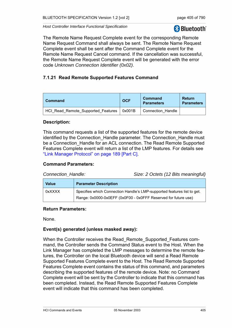
BLUETOOTH SPECIFICATION Version 1.2 [vol 2] page 405 of 790
Host Controller Interface Functional Specification
The Remote Name Request Complete event for the corresponding Remote Name Request Command shall always be sent. The Remote Name Request Complete event shall be sent after the Command Complete event for the Remote Name Request Cancel command. If the cancellation was successful, the Remote Name Request Complete event will be generated with the error code Unknown Connection Identifier (0x02).
7.1.21 Read Remote Supported Features Command
Description:
This command requests a list of the supported features for the remote device identified by the Connection_Handle parameter. The Connection_Handle must be a Connection_Handle for an ACL connection. The Read Remote Supported Features Complete event will return a list of the LMP features. For details see “Link Manager Protocol” on page 189 [Part C].
Command Parameters:
Connection_Handle: Size: 2 Octets (12 Bits meaningful)
Return Parameters:
None.
Event(s) generated (unless masked away):
When the Controller receives the Read_Remote_Supported_Features com-mand, the Controller sends the Command Status event to the Host. When the Link Manager has completed the LMP messages to determine the remote fea-tures, the Controller on the local Bluetooth device will send a Read Remote Supported Features Complete event to the Host. The Read Remote Supported Features Complete event contains the status of this command, and parameters describing the supported features of the remote device. Note: no Command Complete event will be sent by the Controller to indicate that this command has been completed. Instead, the Read Remote Supported Features Complete event will indicate that this command has been completed.
Command OCF Command Parameters
ReturnParameters
HCI_Read_Remote_Supported_Features 0x001B Connection_Handle
Value Parameter Description
0xXXXX Specifies which Connection Handle’s LMP-supported features list to get.Range: 0x0000-0x0EFF (0x0F00 - 0x0FFF Reserved for future use)
HCI Commands and Events 05 November 2003 405

BLUETOOTH SPECIFICATION Version 1.2 [vol 2] page 406 of 790
Host Controller Interface Functional Specification
7.1.22 Read Remote Extended Features Command
Description:
The HCI_Read_Remote_Extended_Features command returns the requested page of the extended LMP features for the remote device identified by the specified connection handle. The connection handle must be the connection handle for an ACL connection. This command is only available if the extended features feature is implemented by the remote device. The Read Remote Extended Features Complete event will return the requested information. For details see “Link Manager Protocol” on page 189 [Part C].
Command Parameters:
Connection_Handle: Size: 2 Octets (12 Bits meaningful)
Page Number: Size: 1 Octet
Return Parameters:
None.
Event(s) generated (unless masked away):
When the Controller receives the HCI_Read_Remote_Extended_Features command the Controller sends the Command Status command to the Host. When the Link Manager has completed the LMP sequence to determine the remote extended features the controller on the local device will generate a Read Remote Extended Features Complete event to the host. The Read Remote Extended Features Complete event contains the page number and the remote features returned by the remote device.
Command OCF Command Parameters
ReturnParameters
HCI_Read_Remote_Extended_Features 0x001C Connection_Handle,Page Number
Value Parameter Description
0xXXXX The connection handle identifying the remote device for which extended feature information is required. Range: 0x0000-0x0EFF (0x0F00-0x0FFF Reserved for future use)
Value Parameter Description
0x00 Requests the normal LMP features as returned by HCI_Read_Remote_Supported_Features
0x01-0xFF Return the corresponding page of features
406 05 November 2003 HCI Commands and Events

BLUETOOTH SPECIFICATION Version 1.2 [vol 2] page 407 of 790
Host Controller Interface Functional Specification
Note: no Command Complete event will ever be sent by the Controller to indi-cate that this command has been completed. Instead the Read Remote Extended Features Complete event will indicate that this command has been completed.
7.1.23 Read Remote Version Information Command
Description:
This command will obtain the values for the version information for the remote Bluetooth device identified by the Connection_Handle parameter. The Connection_Handle must be a Connection_Handle for an ACL connection.
Command Parameters:
Connection_Handle: Size: 2 Octets (12 Bits meaningful)
Return Parameters:
None.
Event(s) generated (unless masked away):
When the Controller receives the Read_Remote_Version_Information com-mand, the Controller sends the Command Status event to the Host. When the Link Manager has completed the LMP messages to determine the remote ver-sion information, the Controller on the local Bluetooth device will send a Read Remote Version Information Complete event to the Host. The Read Remote Version Information Complete event contains the status of this command, and parameters describing the version and subversion of the LMP used by the remote device. Note: no Command Complete event will be sent by the Controller to indicate that this command has been completed. Instead, the Read Remote Version Information Complete event will indicate that this command has been completed.
Command OCF Command Parameters Return Parameters
HCI_Read_Remote_Version_Information
0x001D Connection_Handle
Value Parameter Description
0xXXXX Specifies which Connection Handle’s version information to get.Range: 0x0000-0x0EFF (0x0F00 - 0x0FFF Reserved for future use)
HCI Commands and Events 05 November 2003 407
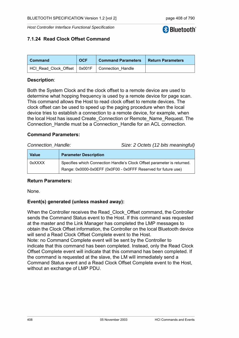
BLUETOOTH SPECIFICATION Version 1.2 [vol 2] page 408 of 790
Host Controller Interface Functional Specification
7.1.24 Read Clock Offset Command
Description:
Both the System Clock and the clock offset to a remote device are used to determine what hopping frequency is used by a remote device for page scan. This command allows the Host to read clock offset to remote devices. The clock offset can be used to speed up the paging procedure when the local device tries to establish a connection to a remote device, for example, when the local Host has issued Create_Connection or Remote_Name_Request. The Connection_Handle must be a Connection_Handle for an ACL connection.
Command Parameters:
Connection_Handle: Size: 2 Octets (12 bits meaningful)
Return Parameters:
None.
Event(s) generated (unless masked away):
When the Controller receives the Read_Clock_Offset command, the Controller sends the Command Status event to the Host. If this command was requested at the master and the Link Manager has completed the LMP messages to obtain the Clock Offset information, the Controller on the local Bluetooth device will send a Read Clock Offset Complete event to the Host.Note: no Command Complete event will be sent by the Controller to indicate that this command has been completed. Instead, only the Read Clock Offset Complete event will indicate that this command has been completed. If the command is requested at the slave, the LM will immediately send a Command Status event and a Read Clock Offset Complete event to the Host, without an exchange of LMP PDU.
Command OCF Command Parameters Return Parameters
HCI_Read_Clock_Offset 0x001F Connection_Handle
Value Parameter Description
0xXXXX Specifies which Connection Handle’s Clock Offset parameter is returned. Range: 0x0000-0x0EFF (0x0F00 - 0x0FFF Reserved for future use)
408 05 November 2003 HCI Commands and Events

BLUETOOTH SPECIFICATION Version 1.2 [vol 2] page 409 of 790
Host Controller Interface Functional Specification
7.1.25 Read LMP Handle Command
Description:
This command will read the current LMP Handle associated with the Connection_Handle. The Connection_Handle must be a SCO or eSCO Han-dle. If the Connection_Handle is a SCO connection handle, then this command shall read the LMP SCO Handle for this connection. If the Connection_Handle is an eSCO connection handle, then this command shall read the LMP eSCO Handle for this connection.
Command Parameters:
Connection_Handle: Size 2 Octets (12 bits meaningful)
Return Parameters:
Status: Size: 1 Octet
Connection_Handle: Size: 2 Octets (12 bits meaningful)
Command OCF Command Parameters Return Parameters
HCI_Read_LMP_Handle 0x0020 Connection_Handle Status, Connection_Handle, LMP_Handle,Reserved
Value Parameter Description
0xXXXX Connection Handle to be used to identify which connection to be used for reading the LMP Handle. This must be a synchronous handle.Range: 0x0000-0x0EFF (0x0F00 – 0x0FFF Reserved for future use)
Value Parameter Description
0x00 Read_LMP_Handle command succeeded.
0x01 – 0xFF Read_LMP_Handle command failed. See “Error Codes” on page 291 [Part D] for list of Error Codes.
Value Parameter Description
0xXXXX The Connection Handle for the Connection for which the LMP_Handle has been read.Range: 0x0000-0x0EFF (0x0F00 – 0x0FFF Reserved for future use)
HCI Commands and Events 05 November 2003 409
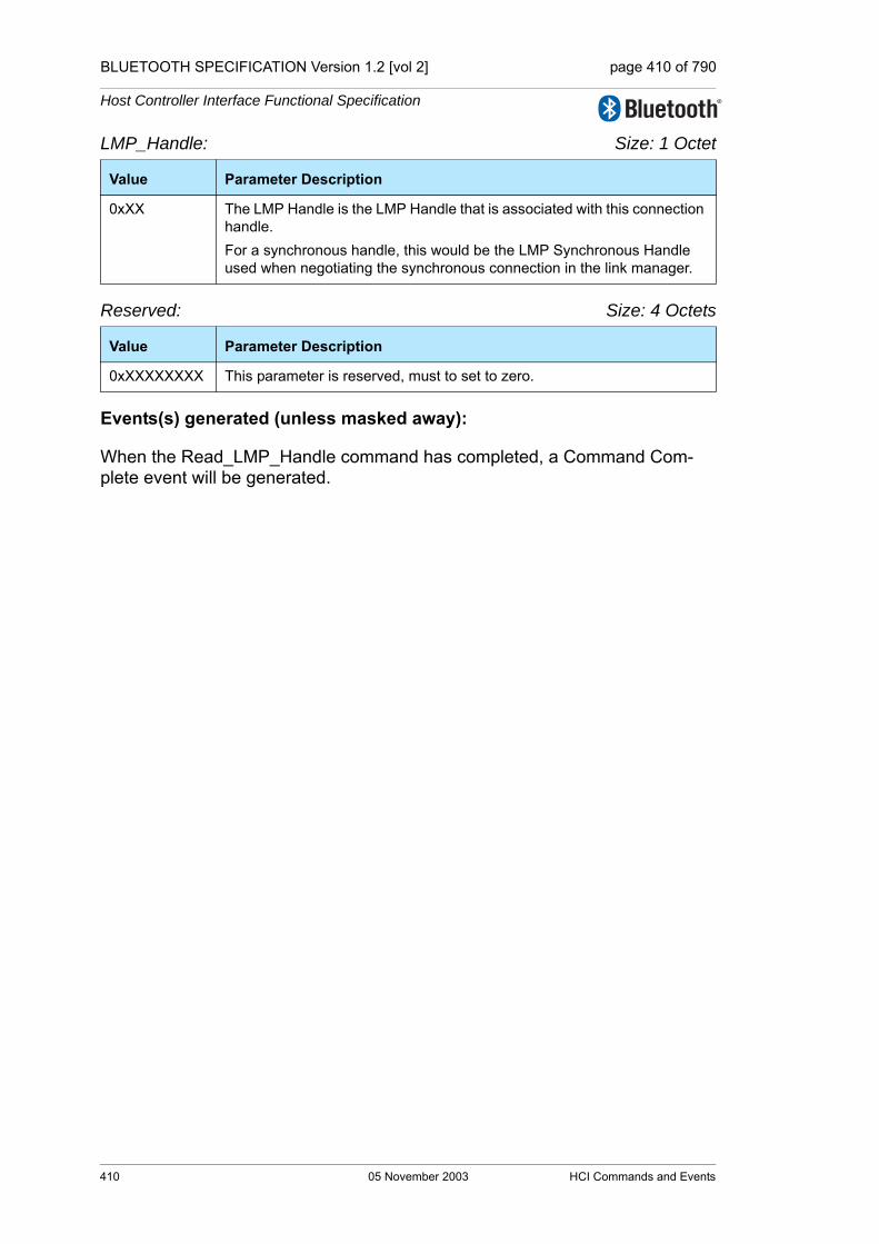
BLUETOOTH SPECIFICATION Version 1.2 [vol 2] page 410 of 790
Host Controller Interface Functional Specification
LMP_Handle: Size: 1 Octet
Reserved: Size: 4 Octets
Events(s) generated (unless masked away):
When the Read_LMP_Handle command has completed, a Command Com-plete event will be generated.
Value Parameter Description
0xXX The LMP Handle is the LMP Handle that is associated with this connection handle.For a synchronous handle, this would be the LMP Synchronous Handle used when negotiating the synchronous connection in the link manager.
Value Parameter Description
0xXXXXXXXX This parameter is reserved, must to set to zero.
410 05 November 2003 HCI Commands and Events

BLUETOOTH SPECIFICATION Version 1.2 [vol 2] page 411 of 790
Host Controller Interface Functional Specification
7.1.26 Setup Synchronous Connection Command
Description:
The HCI Setup Synchronous Connection command adds a new or modifies an existing synchronous logical transport (SCO or eSCO) on a physical link depending on the Connection_Handle parameter specified. If the Connection_Handle refers to an ACL link a new synchronous logical transport will be added. If the Connection_Handle refers to an already existing synchro-nous logical transport (eSCO only) this link will be modified.The parameters are specified per connection. This synchronous connection can be used to transfer synchronous voice at 64kbps or transparent synchronous data.
When used to setup a new synchronous logical transport, the Connection_Handle parameter shall specify an ACL connection with which the new synchronous con-nection will be associated. The other parameters relate to the negotiation of the link, and may be reconfigured during the lifetime of the link. The transmit and receive bandwidth specify how much bandwidth shall be available for transmitting and for receiving data. While in many cases the receive and transmit bandwidth parameters may be equal, they may be different. The latency specifies an upper limit to the time in milliseconds between the eSCO (or SCO) instants, plus the size of the retransmission window, plus the length of the reserved synchronous slots for this logical transport. The content format specifies the settings for voice or transparent data on this connection. The retransmission effort specifies the extra resources that are allocated to this connection if a packet may need to be retrans-mitted. The Retransmission_Effort parameter shall be set to indicate the required behaviour, or to don't care.
When used to modify an existing synchronous logical transport, the Transmit_Bandwidth, Receive_Bandwidth and Voice_Settings shall be set to the same values as were used during the initial setup. The Packet_Type, Retransmission_Effort and Max_Latency parameters may be modified.
The Packet_Type field is a bitmap specifying which packet types the LM shall accept in the negotiation of the link parameters. Multiple packet types are spec-ified by bitwise OR of the packet type codes in the table. At least one packet type must be specified for each negotiation. It is recommended to enable as many packet types as possible. Note that it is allowed to enable packet types that are not supported by the local device.
Command OCF Command Parameters Return Parameters
HCI_Setup_Synchronous_Connection
0x0028 Connection_HandleTransmit_BandwidthReceive_BandwidthMax_LatencyVoice_SettingRetransmission_EffortPacket Type
HCI Commands and Events 05 November 2003 411
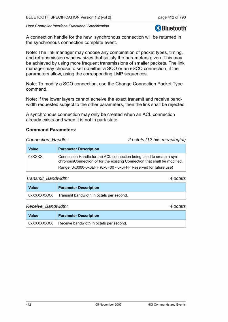
BLUETOOTH SPECIFICATION Version 1.2 [vol 2] page 412 of 790
Host Controller Interface Functional Specification
A connection handle for the new synchronous connection will be returned in the synchronous connection complete event.
Note: The link manager may choose any combination of packet types, timing, and retransmission window sizes that satisfy the parameters given. This may be achieved by using more frequent transmissions of smaller packets. The link manager may choose to set up either a SCO or an eSCO connection, if the parameters allow, using the corresponding LMP sequences.
Note: To modify a SCO connection, use the Change Connection Packet Type command.
Note: If the lower layers cannot acheive the exact transmit and receive band-width requested subject to the other parameters, then the link shall be rejected.
A synchronous connection may only be created when an ACL connection already exists and when it is not in park state.
Command Parameters:
Connection_Handle: 2 octets (12 bits meaningful)
Transmit_Bandwidth: 4 octets
Receive_Bandwidth: 4 octets
Value Parameter Description
0xXXXX Connection Handle for the ACL connection being used to create a syn-chronousConnection or for the existing Connection that shall be modified.Range: 0x0000-0x0EFF (0x0F00 - 0x0FFF Reserved for future use)
Value Parameter Description
0xXXXXXXXX Transmit bandwidth in octets per second.
Value Parameter Description
0xXXXXXXXX Receive bandwidth in octets per second.
412 05 November 2003 HCI Commands and Events

BLUETOOTH SPECIFICATION Version 1.2 [vol 2] page 413 of 790
Host Controller Interface Functional Specification
Max_Latency: 2 octets
Voice_Setting: 2 octets (10 bits meaningful)
Retransmission_Effort: 1 octet
Value Parameter Description
0x0000-0x0003
Reserved
0x0004-0xFFFE
This is a value in milliseconds representing the upper limit of the sum of the synchronous interval and the size of the eSCO window.
0xFFFF Don't care.
Value Parameter Description
See Section 6.12 on page 361.
Value Parameter Description
0x00 No retransmissions
0x01 At least one retransmission, optimize for power consumption.
0x02 At least one retransmission, optimize for link quality
0xFF Don’t care
0x03 – 0xFE Reserved
HCI Commands and Events 05 November 2003 413

BLUETOOTH SPECIFICATION Version 1.2 [vol 2] page 414 of 790
Host Controller Interface Functional Specification
Packet_Type: 2 octets
Return Parameters:
None
Event(s) generated (unless masked away)
When the Controller receives the Setup_Synchronous_Connection command, it sends the Command Status event to the Host. In addition, when the LM determines the connection is established, the local Controller will send a Syn-chronous Connection Complete event to the local Host, and the remote Con-troller will send a Synchronous Connection Complete event or a Connection Complete event to the remote Host. The synchronous Connection Complete event contains the Connection Handle if this command is successful.
If this command is used to change the parameters of an existing eSCO link, the Synchronous Connection Changed Event is sent to both hosts. In this case no Connection Setup Complete Event or Connection Request Event will be sent to either host. This command cannot be used to change the parameters of an SCO link.
Note: no Command Complete event will be sent by the Controller to indicate that this command has been completed. Instead, the synchronous Connection Complete event will indicate that this command has been completed.
Value Parameter Description
0x0001 HV1
0x0002 HV2
0x0004 HV3
0x0008 EV3
0x0010 EV4
0x0020 EV5
0x0040 Reserved for future use
0x0080 Reserved for future use
0x0100 Reserved for future use
0x0200 Reserved for future use
0x0400 Reserved for future use
0x0800 Reserved for future use
0x1000 Reserved for future use
0x2000 Reserved for future use
0x4000 Reserved for future use
0x8000 Reserved for future use
414 05 November 2003 HCI Commands and Events

BLUETOOTH SPECIFICATION Version 1.2 [vol 2] page 415 of 790
Host Controller Interface Functional Specification
7.1.27 Accept Synchronous Connection Request Command
Description:
The Accept_Synchronous_Connection_Request command is used to accept an incoming request for a synchronous connection and to inform the local Link Manager about the acceptable parameter values for the synchronous connec-tion. The Command shall only be issued after a Connection_Request event with link type SCO or eSCO has occurred. Connection_Request event contains the BD_ADDR of the device requesting the connection. The decision to accept a connection must be taken before the connection accept timeout expires on the local device.
The parameter set of the Accept_Synchronous_Connection_Request com-mand is the same as for the Setup_Synchronous_Connection command. The Transmit_Bandwidth and Receive_Bandwidth values are required values for the new link and shall be met. The Max_Latency is an upper bound to the acceptable latency for the Link, as defined in Section 7.1.26 on page 411 Setup_Synchronous_Connection and shall not be exceeded. Content_Format specifies the encoding in the same way as in the Setup_Synchronous_Connection command and shall be met. The Retransmission_Effort parameter shall be set to indicate the required behav-iour, or to don't care. The Packet_Type parameter is a bit mask specifying the synchronous packet types that are allowed on the link and shall be met. The reserved bits in the Packet_Type field shall be set to one.
If the Link Type of the incoming request is SCO, then only the Transmit_Bandwidth, Max_Latency, Content_Format, and Packet_Type fields are valid.
If the Connection_Request event is masked away, and the Controller is not set to auto-accept this connection attempt, the Controller will automatically reject it. If the controller is set to automatically accept the connection attempt, the LM should assume default parameters. In that case the Synchronous_Connection_Complete Event shall be generated, unless masked away.
Command OCF Command Parameters Return Parameters
HCI_Accept_Synchronous_Connection_Request
0x0029 BD_ADDRTransmit_BandwidthReceive_BandwidthMax_LatencyContent_FormatRetransmission_EffortPacket_Type
HCI Commands and Events 05 November 2003 415

BLUETOOTH SPECIFICATION Version 1.2 [vol 2] page 416 of 790
Host Controller Interface Functional Specification
Command Parameters:
BD_ADDR: 6 octets
Transmit_Bandwidth: 4 octets
Default: Don’t care
Receive_Bandwidth: 4 octets
Default: Don’t care
Max_Latency: 2 octets
Default: Don't care
Value Parameter Description
0xXXXXXXXXXXXXX BD_ADDR of the device requesting the connection
Value Parameter Description
0x00000000-0xFFFFFFFE Maximum possible transmit bandwidth in octets per second.
0xFFFFFFFF Don’t care
Value Parameter Description
0x00000000-0xFFFFFFFE Maximum possible receive bandwidth in octets per second.
0xFFFFFFFF Don’t care
Value Parameter Description
0x0000-0x0003
Reserved
0x0004-0xFFFE
This is a value in milliseconds representing the upper limit of the sum of the synchronous interval and the size of the eSCO window.
0xFFFF Don't care.
416 05 November 2003 HCI Commands and Events

BLUETOOTH SPECIFICATION Version 1.2 [vol 2] page 417 of 790
Host Controller Interface Functional Specification
Content_Format: 2 octets (10 bits meaningful)
Default: When links are auto-accepted, the values written by the HCI_Write_Voice_Settings are used.
Retransmission_Effort: 1 octet
Default: Don't care
Value Parameter Description
00XXXXXXXX Input Coding: Linear
01XXXXXXXX Input Coding: u-law
10XXXXXXXX Input Coding: A-law
11XXXXXXXX Reserved for future use.
XX00XXXXXX Input Data Format: 1’s complement
XX01XXXXXX Input Data Format: 2’s complement
XX10XXXXXX Input Data Format: Sign-Magnitude
XX11XXXXXX Input Data Format: Unsigned
XXXX0XXXXX Input Sample Size: 8 bit (only for Linear PCM)
XXXX1XXXXX Input Sample Size: 16 bit (only for Linear PCM)
XXXXXnnnXX Linear PCM Bit Position: number of bit positions that MSB of sample is away from starting at MSB (only for Linear PCM)
XXXXXXXX00 Air Coding Format: CVSD
XXXXXXXX01 Air Coding Format: u-law
XXXXXXXX10 Air Coding Format: A-law
XXXXXXXX11 Air Coding Format: Transparent Data
Value Parameter Description
0x00 No retransmissions
0x01 At least one retransmission, optimize for power consumption.
0x02 At least one retransmission, optimize for link quality.
0x03-0xFE Reserved
0xFF Don’t care
HCI Commands and Events 05 November 2003 417

BLUETOOTH SPECIFICATION Version 1.2 [vol 2] page 418 of 790
Host Controller Interface Functional Specification
Packet_Type: 2 octets
Default: 0xFFFF
Return Parameters:
None
Event(s) generated (unless masked away):
The Accept_Synchronous_Request command will cause the Command Status event to be sent from the Host Controller when the Host Controller starts set-ting up the connection. When the link setup is complete, the local Controller will send a Synchronous Connection Complete event to its Host, and the remote Controller will send a Connection Complete event or a Synchronous Connec-tion Complete event to the Host. The Synchronous Connection Complete will contain the connection handle and the link parameters if the setup is success-ful. No Command Complete event will be sent by the host controller as the result of this command.
Value Parameter Description
0x0001 HV1
0x0002 HV2
0x0004 HV3
0x0008 EV3
0x0010 EV4
0x0020 EV5
0x0040 Reserved for future use
0x0080 Reserved for future use
0x0100 Reserved for future use
0x0200 Reserved for future use
0x0400 Reserved for future use
0x0800 Reserved for future use
0x1000 Reserved for future use
0x2000 Reserved for future use
0x4000 Reserved for future use
0x8000 Reserved for future use
418 05 November 2003 HCI Commands and Events

BLUETOOTH SPECIFICATION Version 1.2 [vol 2] page 419 of 790
Host Controller Interface Functional Specification
7.1.28 Reject Synchronous Connection Request Command
Description:
The Reject_Synchronous_Connection_Request is used to decline an incoming request for a synchronous link. It shall only be issued after a Connection Request Event with Link Type equal to SCO or eSCO has occurred. The Con-nection Request Event contains the BD_ADDR of the device requesting the connection. The Reason parameter will be returned to the initiating host in the Status parameter of the Synchronous connection complete event on the remote side.
Command Parameters:
BD_ADDR: 6 octets
Reason: 1 octet
Return Parameters:
None.
Event(s) Generated (unless masked away):
When the Host Controller receives the Reject_Synchronous_Connection_Request, it sends a Command Status Event to the Host. When the setup is terminated, the local Controller will send a Syn-chronous Connection Complete event to its Host, and the remote Controller will send a Connection Complete event or a Synchronous Connection Complete event to the Host with the Reason code from this command. No Command complete Event will be sent by the Host Controller to indicate that this com-mand has been completed.
Command OCF Command Parameters Return Parameters
HCI_Reject_Synchronous_Connection_Request
0x002A BD_ADDRReason
Value Parameter Description
0xXXXXXXXXXXXXX BD_ADDR of the device requesting the connection
Value Parameter Description
0x0D-0x0F Host Reject Error Code. See “Error Codes” on page 291 [Part D] for error codes and description.
HCI Commands and Events 05 November 2003 419

BLUETOOTH SPECIFICATION Version 1.2 [vol 2] page 420 of 790
Host Controller Interface Functional Specification
7.2 LINK POLICY COMMANDS
The Link Policy Commands provide methods for the Host to affect how the Link Manager manages the piconet. When Link Policy Commands are used, the LM still controls how Bluetooth piconets and scatternets are established and main-tained, depending on adjustable policy parameters. These policy commands modify the Link Manager behavior that can result in changes to the link layer connections with Bluetooth remote devices. Note: only one ACL connection can exist between two Bluetooth Devices, and therefore there can only be one ACL HCI Connection Handle for each physical link layer Connection. The Bluetooth Controller provides policy adjustment mechanisms to provide support for a number of different policies. This capabil-ity allows one Bluetooth module to be used to support many different usage models, and the same Bluetooth module can be incorporated in many different types of Bluetooth devices. For the Link Policy Commands, the OGF is defined as 0x02.
7.2.1 Hold Mode Command
Description:
The Hold_Mode command is used to alter the behavior of the Link Manager, and have it place the ACL baseband connection associated by the specified Connection Handle into the hold mode. The Hold_Mode_Max_Interval and Hold_Mode_Min_Interval command parameters specify the length of time the Host wants to put the connection into the hold mode. The local and remote devices will negotiate the length in the hold mode. The Hold_Mode_Max_Interval parameter is used to specify the maximum length of the Hold interval for which the Host may actually enter into the hold mode after negotiation with the remote device. The Hold interval defines the amount of time between when the Hold Mode begins and when the Hold Mode is completed. The Hold_Mode_Min_Interval parameter is used to specify the minimum length of the Hold interval for which the Host may actually enter into the hold mode after the negotiation with the remote device. Therefore the Hold_Mode_Min_Interval cannot be greater than the Hold_Mode_Max_Interval. The Controller will return the actual Hold interval in the Interval parameter of the Mode Change event, if the command is successful. This command enables the Host to support a low-power policy for itself or several other Bluetooth devices, and allows the devices to enter Inquiry Scan, Page Scan, and a number of other possible actions. Note: the connection handle cannot be of the SCO or eSCO link type
Command OCF Command Parameters Return Parameters
HCI_Hold_Mode 0x0001 Connection_Handle, Hold_Mode_Max_Interval,Hold_Mode_Min_Interval
420 05 November 2003 HCI Commands and Events
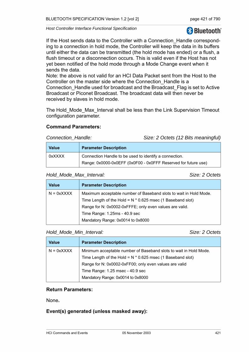
BLUETOOTH SPECIFICATION Version 1.2 [vol 2] page 421 of 790
Host Controller Interface Functional Specification
If the Host sends data to the Controller with a Connection_Handle correspond-ing to a connection in hold mode, the Controller will keep the data in its buffers until either the data can be transmitted (the hold mode has ended) or a flush, a flush timeout or a disconnection occurs. This is valid even if the Host has not yet been notified of the hold mode through a Mode Change event when it sends the data.Note: the above is not valid for an HCI Data Packet sent from the Host to the Controller on the master side where the Connection_Handle is a Connection_Handle used for broadcast and the Broadcast_Flag is set to Active Broadcast or Piconet Broadcast. The broadcast data will then never be received by slaves in hold mode.
The Hold_Mode_Max_Interval shall be less than the Link Supervision Timeout configuration parameter.
Command Parameters:
Connection_Handle: Size: 2 Octets (12 Bits meaningful)
Hold_Mode_Max_Interval: Size: 2 Octets
Hold_Mode_Min_Interval: Size: 2 Octets
Return Parameters:
None.
Event(s) generated (unless masked away):
Value Parameter Description
0xXXXX Connection Handle to be used to identify a connection.Range: 0x0000-0x0EFF (0x0F00 - 0x0FFF Reserved for future use)
Value Parameter Description
N = 0xXXXX Maximum acceptable number of Baseband slots to wait in Hold Mode.Time Length of the Hold = N * 0.625 msec (1 Baseband slot)Range for N: 0x0002-0xFFFE; only even values are valid.Time Range: 1.25ms - 40.9 secMandatory Range: 0x0014 to 0x8000
Value Parameter Description
N = 0xXXXX Minimum acceptable number of Baseband slots to wait in Hold Mode.Time Length of the Hold = N * 0.625 msec (1 Baseband slot)Range for N: 0x0002-0xFF00; only even values are validTime Range: 1.25 msec - 40.9 sec Mandatory Range: 0x0014 to 0x8000
HCI Commands and Events 05 November 2003 421

BLUETOOTH SPECIFICATION Version 1.2 [vol 2] page 422 of 790
Host Controller Interface Functional Specification
The Controller sends the Command Status event for this command to the Host when it has received the Hold_Mode command. The Mode Change event will occur when the Hold Mode has started and the Mode Change event will occur again when the Hold Mode has completed for the specified connection handle. The Mode Change event signaling the end of the Hold Mode is an estimation of the hold mode ending if the event is for a remote Bluetooth device.Note: no Command Complete event will be sent by the Controller to indicate that this command has been completed. Instead, only the Mode Change event will indicate that this command has been completed. If an error occurs after the Command Status event has occurred, then the status in the Mode Change event will indicate the error.
7.2.2 Sniff Mode Command
Description: The Sniff Mode command is used to alter the behavior of the Link Manager and have it place the ACL baseband connection associated with the specified Con-nection Handle into the sniff mode. The Connection_Handle command param-eter is used to identify which ACL link connection is to be placed in sniff mode. The Sniff_Max_Interval and Sniff_Min_Interval command parameters are used to specify the requested acceptable maximum and minimum periods in the Sniff Mode. The Sniff_Min_Interval shall not be greater than the Sniff_Max_Interval. The sniff interval defines the amount of time between each consecutive sniff period. The Controller will return the actual sniff interval in the Interval parameter of the Mode Change event, if the command is successful. For a description of the meaning of the Sniff_Attempt and Sniff_Timeout parameters, see Baseband Specification, Section 8.7, on page 163. Sniff_Attempt is there called Nsniff attempt and Sniff_Timeout is called Nsniff time-out. This command enables the Host to support a low-power policy for itself or several other Bluetooth devices, and allows the devices to enter Inquiry Scan, Page Scan, and a number of other possible actions.Note: in addition, the connection handle cannot be one of the synchronous link types. If the Host sends data to the Controller with a Connection_Handle corre-sponding to a connection in sniff mode, the Controller will keep the data in its buffers until either the data can be transmitted or a flush, a flush timeout or a disconnection occurs. This is valid even if the Host has not yet been notified of the sniff mode through a Mode Change event when it sends the data. Note that it is possible for the master to transmit data to a slave without exiting sniff mode
Command OCF Command Parameters Return Parameters
HCI_Sniff_Mode 0x0003 Connection_Handle,Sniff_Max_Interval,Sniff_Min_Interval,Sniff_Attempt,Sniff_Timeout
422 05 November 2003 HCI Commands and Events

BLUETOOTH SPECIFICATION Version 1.2 [vol 2] page 423 of 790
Host Controller Interface Functional Specification
(see description in Baseband Specification, Section 8.7, on page 163 ).Note: the above is not valid for an HCI Data Packet sent from the Host to the Controller on the master side where the Connection_Handle is a Connection_Handle used for broadcast and the Broadcast_Flag is set to Active Broadcast or Piconet Broadcast. In that case, the broadcast data will only be received by a slave in sniff mode if that slave happens to listen to the master when the broadcast is made.The Sniff_Max_Interval shall be less than the Link Supervision Timeout config-uration parameter.
Command Parameters: Connection_Handle: Size: 2 Octets (12 Bits meaningful)
Sniff_Max_Interval: Size: 2 Octets
Sniff_Min_Interval: Size: 2 Octets
Sniff_Attempt: Size: 2 Octets
Value Parameter Description
0xXXXX Connection Handle to be used to identify a connection.Range: 0x0000-0x0EFF (0x0F00 - 0x0FFF Reserved for future use)
Value Parameter Description
N = 0xXXXX Range: 0x0002 to 0xFFFE; only even values are validMandatory Range: 0x0006 to 0x0540Time = N * 0.625 msecTime Range: 1.25 msec to 40.9 sec
Value Parameter Description
N = 0xXXXX Range: 0x0002 to 0xFFFE; only even values are validMandatory Range: 0x0006 to 0x0540Time = N * 0.625 msecTime Range: 1.25 msec to 40.9 sec)
Value Parameter Description
N = 0xXXXX Number of Baseband receive slots for sniff attempt.Length = N* 1.25 msec Range for N: 0x0001 – 0x7FFFTime Range: 0.625msec - 40.9 SecondsMandatory Range for Controller: 1 to Tsniff/2
HCI Commands and Events 05 November 2003 423

BLUETOOTH SPECIFICATION Version 1.2 [vol 2] page 424 of 790
Host Controller Interface Functional Specification
Sniff_Timeout: Size: 2 Octets
Return Parameters:
None.
Event(s) generated (unless masked away):
The Controller sends the Command Status event for this command to the Host when it has received the Sniff_Mode command. The Mode Change event will occur when the Sniff Mode has started for the specified connection handle.Note: no Command Complete event will be sent by the Controller to indicate that this command has been completed. Instead only the Mode Change event will indicate that this command has been completed. If an error occurs after the Command Status event has occurred, then the status in the Mode Change event will indicate the error.
Value Parameter Description
N = 0xXXXX Number of Baseband receive slots for sniff timeout. Length = N * 1.25 msecRange for N: 0x0000 – 0x7FFFTime Range: 0 msec - 40.9 SecondsMandatory Range for Controller: 0 to 0x0028
424 05 November 2003 HCI Commands and Events
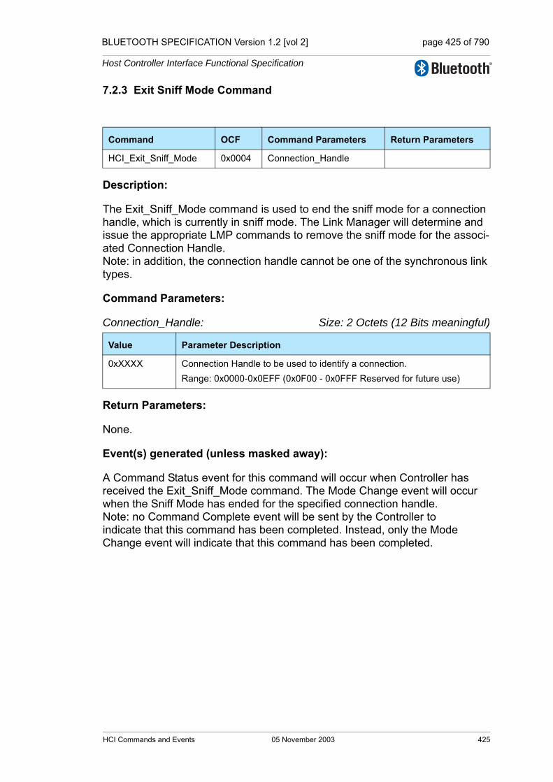
BLUETOOTH SPECIFICATION Version 1.2 [vol 2] page 425 of 790
Host Controller Interface Functional Specification
7.2.3 Exit Sniff Mode Command
Description:
The Exit_Sniff_Mode command is used to end the sniff mode for a connection handle, which is currently in sniff mode. The Link Manager will determine and issue the appropriate LMP commands to remove the sniff mode for the associ-ated Connection Handle. Note: in addition, the connection handle cannot be one of the synchronous link types.
Command Parameters:
Connection_Handle: Size: 2 Octets (12 Bits meaningful)
Return Parameters:
None.
Event(s) generated (unless masked away):
A Command Status event for this command will occur when Controller has received the Exit_Sniff_Mode command. The Mode Change event will occur when the Sniff Mode has ended for the specified connection handle.Note: no Command Complete event will be sent by the Controller to indicate that this command has been completed. Instead, only the Mode Change event will indicate that this command has been completed.
Command OCF Command Parameters Return Parameters
HCI_Exit_Sniff_Mode 0x0004 Connection_Handle
Value Parameter Description
0xXXXX Connection Handle to be used to identify a connection.Range: 0x0000-0x0EFF (0x0F00 - 0x0FFF Reserved for future use)
HCI Commands and Events 05 November 2003 425

BLUETOOTH SPECIFICATION Version 1.2 [vol 2] page 426 of 790
Host Controller Interface Functional Specification
7.2.4 Park State Command
Description:
The Park State command is used to alter the behavior of the Link Manager, and have the LM place the baseband connection associated by the specified Connec-tion Handle into Park state. The Connection_Handle command parameter is used to identify which connection is to be placed in Park state. The Connection_Handle must be a Connection_Handle for an ACL connection. The Beacon Interval com-mand parameters specify the acceptable length of the interval between beacons. However, the remote device may request shorter interval. The Beacon_Max_Interval parameter specifies the acceptable longest length of the interval between beacons. The Beacon_Min_Interval parameter specifies the acceptable shortest length of the interval between beacons. Therefore, the Beacon Min Interval cannot be greater than the Beacon Max Interval. The Controller will return the actual Beacon interval in the Interval parameter of the Mode Change event, if the command is successful. This command enables the Host to support a low-power policy for itself or several other Bluetooth devices, allows the devices to enter Inquiry Scan, Page Scan, provides support for large number of Bluetooth Devices in a single piconet, and a number of other possible activities.Note: when the Host issues the Park State command, no Connection Handles for synchronous connections are allowed to exist to the remote device that is identified by the Connection_Handle parameter. If one or more Connection Handles for syn-chronous connections exist to that device, depending on the implementation, a Command Status event or a Mode Change event (following a Command Status event where Status=0x00) will be returned with the error code 0x0C Command Disallowed.If the Host sends data to the Controller with a Connection_Handle corresponding to a parked connection, the Controller will keep the data in its buffers until either the data can be transmitted (after unpark) or a flush, a flush timeout or a disconnection occurs. This is valid even if the Host has not yet been notified of park state through a Mode Change event when it sends the data.Note: the above is not valid for an HCI Data Packet sent from the Host to the Con-troller on the master side where the Connection_Handle is a Connection_Handle used for Piconet Broadcast and the Broadcast_Flag is set to Piconet Broadcast. In that case, slaves in park state will also receive the broadcast data. (If the Broadcast_Flag is set to Active Broadcast, the broadcast data will usually not be received by slaves in park state.)It is possible for the Controller to do an automatic unpark to transmit data and then park the connection again depending on the value of the Link_Policy_Settings parameter (see Write_Link_Policy_Settings) and depending on whether the imple-
Command OCF Command Parameters Return Parameters
HCI_Park_State 0x0005 Connection_Handle,Beacon_Max_Interval,Beacon_Min_Interval
426 05 November 2003 HCI Commands and Events
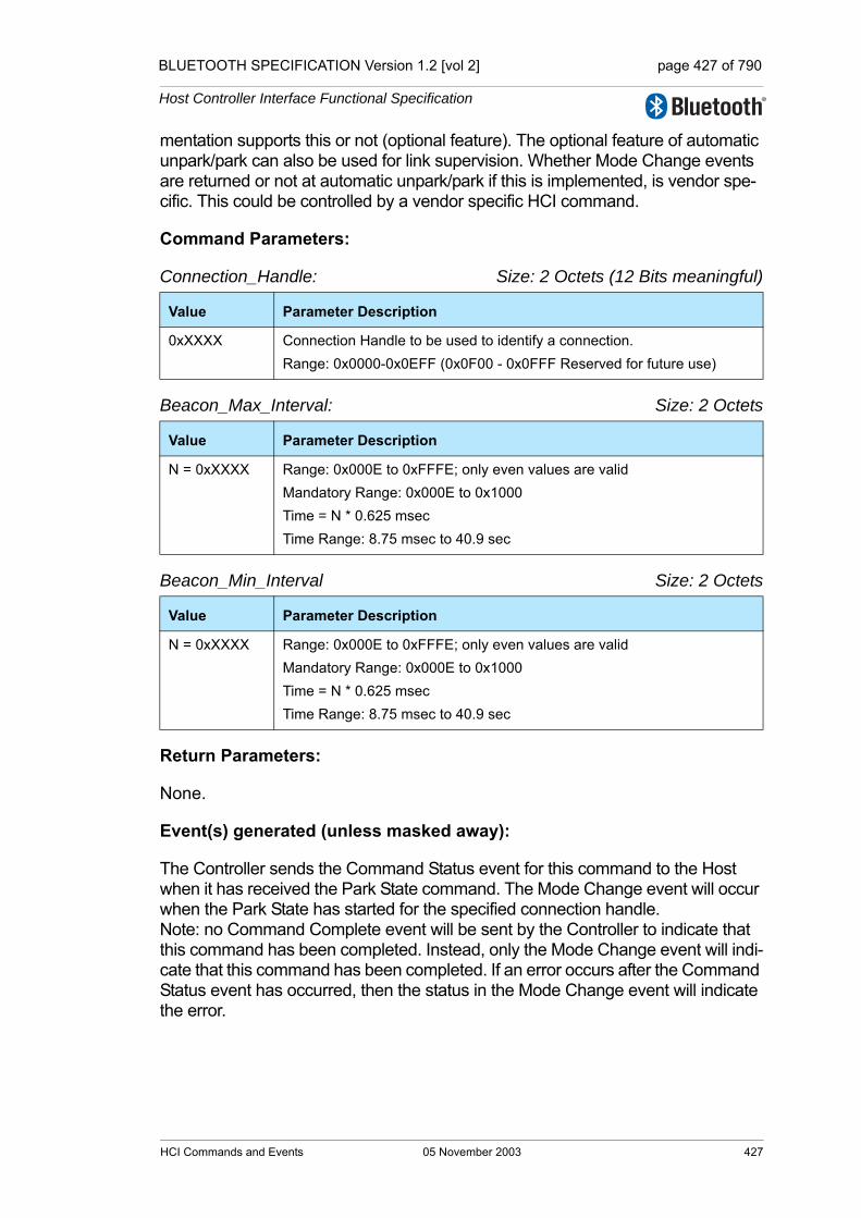
BLUETOOTH SPECIFICATION Version 1.2 [vol 2] page 427 of 790
Host Controller Interface Functional Specification
mentation supports this or not (optional feature). The optional feature of automatic unpark/park can also be used for link supervision. Whether Mode Change events are returned or not at automatic unpark/park if this is implemented, is vendor spe-cific. This could be controlled by a vendor specific HCI command.
Command Parameters:
Connection_Handle: Size: 2 Octets (12 Bits meaningful)
Beacon_Max_Interval: Size: 2 Octets
Beacon_Min_Interval Size: 2 Octets
Return Parameters:
None.
Event(s) generated (unless masked away):
The Controller sends the Command Status event for this command to the Host when it has received the Park State command. The Mode Change event will occur when the Park State has started for the specified connection handle.Note: no Command Complete event will be sent by the Controller to indicate that this command has been completed. Instead, only the Mode Change event will indi-cate that this command has been completed. If an error occurs after the Command Status event has occurred, then the status in the Mode Change event will indicate the error.
Value Parameter Description
0xXXXX Connection Handle to be used to identify a connection.Range: 0x0000-0x0EFF (0x0F00 - 0x0FFF Reserved for future use)
Value Parameter Description
N = 0xXXXX Range: 0x000E to 0xFFFE; only even values are validMandatory Range: 0x000E to 0x1000Time = N * 0.625 msecTime Range: 8.75 msec to 40.9 sec
Value Parameter Description
N = 0xXXXX Range: 0x000E to 0xFFFE; only even values are validMandatory Range: 0x000E to 0x1000Time = N * 0.625 msecTime Range: 8.75 msec to 40.9 sec
HCI Commands and Events 05 November 2003 427

BLUETOOTH SPECIFICATION Version 1.2 [vol 2] page 428 of 790
Host Controller Interface Functional Specification
7.2.5 Exit Park State Command
Description:
The Exit_Park_State command is used to switch the Bluetooth device from park state back to the active mode. This command may only be issued when the device associated with the specified Connection Handle is in park state. The Connection_Handle must be a Connection_Handle for an ACL connection. This function does not complete immediately.
Command Parameters:
Connection_Handle: Size: 2 Octets (12 Bits meaningful)
Return Parameters:
None.
Event(s) generated (unless masked away):
A Command Status event for this command will occur when the Controller has received the Exit_Park_State command. The Mode Change event will occur when park state has ended for the specified connection handle.Note: no Command Complete event will be sent by the Controller to indicate that this command has been completed. Instead, only the Mode Change event will indicate that this command has been completed.
Command OCF Command Parameters Return Parameters
HCI_Exit_Park_State 0x0006 Connection_Handle
Value Parameter Description
0xXXXX Connection Handle to be used to identify a connection.Range: 0x0000-0x0EFF (0x0F00 - 0x0FFF Reserved for future use)
428 05 November 2003 HCI Commands and Events

BLUETOOTH SPECIFICATION Version 1.2 [vol 2] page 429 of 790
Host Controller Interface Functional Specification
7.2.6 QoS Setup Command
Description:
The QoS_Setup command is used to specify Quality of Service parameters for a connection handle. The Connection_Handle must be a Connection_Handle for an ACL connection. These QoS parameter are the same parameters as L2CAP QoS. For more detail see “Logical Link Control and Adaptation Protocol Specification” on page 15[vol. 3]. This allows the Link Manager to have all of the information about what the Host is requesting for each connection. The LM will determine if the QoS parameters can be met. Bluetooth devices that are both slaves and masters can use this command. When a device is a slave, this command will trigger an LMP request to the master to provide the slave with the specified QoS as determined by the LM. When a device is a master, this command is used to request a slave device to accept the specified QoS as determined by the LM of the master. The Connection_Handle command parameter is used to identify for which connection the QoS request is requested.
Command Parameters:
Connection_Handle: Size: 2 Octets (12 Bits meaningful)
Flags: Size: 1 Octet
Command OCF Command Parameters Return Parameters
HCI_QoS_Setup 0x0007 Connection_Handle,Flags,Service_Type,Token_Rate,Peak_Bandwidth,Latency,Delay_Variation
Value Parameter Description
0xXXXX Connection Handle to be used to identify which connection for the QoS Setup.Range: 0x0000-0x0EFF (0x0F00 - 0x0FFF Reserved for future use)
Value Parameter Description
0x00 – 0xFF Reserved for Future Use.
HCI Commands and Events 05 November 2003 429
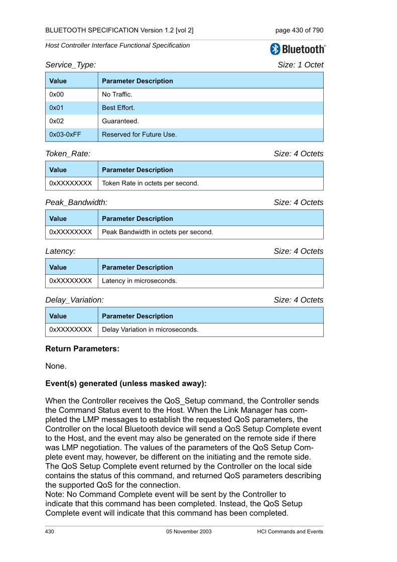
BLUETOOTH SPECIFICATION Version 1.2 [vol 2] page 430 of 790
Host Controller Interface Functional Specification
Service_Type: Size: 1 Octet
Token_Rate: Size: 4 Octets
Peak_Bandwidth: Size: 4 Octets
Latency: Size: 4 Octets
Delay_Variation: Size: 4 Octets
Return Parameters:
None.
Event(s) generated (unless masked away):
When the Controller receives the QoS_Setup command, the Controller sends the Command Status event to the Host. When the Link Manager has com-pleted the LMP messages to establish the requested QoS parameters, the Controller on the local Bluetooth device will send a QoS Setup Complete event to the Host, and the event may also be generated on the remote side if there was LMP negotiation. The values of the parameters of the QoS Setup Com-plete event may, however, be different on the initiating and the remote side. The QoS Setup Complete event returned by the Controller on the local side contains the status of this command, and returned QoS parameters describing the supported QoS for the connection. Note: No Command Complete event will be sent by the Controller to indicate that this command has been completed. Instead, the QoS Setup Complete event will indicate that this command has been completed.
Value Parameter Description
0x00 No Traffic.
0x01 Best Effort.
0x02 Guaranteed.
0x03-0xFF Reserved for Future Use.
Value Parameter Description
0xXXXXXXXX Token Rate in octets per second.
Value Parameter Description
0xXXXXXXXX Peak Bandwidth in octets per second.
Value Parameter Description
0xXXXXXXXX Latency in microseconds.
Value Parameter Description
0xXXXXXXXX Delay Variation in microseconds.
430 05 November 2003 HCI Commands and Events

BLUETOOTH SPECIFICATION Version 1.2 [vol 2] page 431 of 790
Host Controller Interface Functional Specification
7.2.7 Role Discovery Command
Description:
The Role_Discovery command is used for a Bluetooth device to determine which role the device is performing for a particular Connection Handle. The Connection_Handle must be a Connection_Handle for an ACL connection.
Command Parameters: Connection_Handle: Size: 2 Octets (12 Bits meaningful)
Return Parameters:Status: Size: 1 Octet
Connection_Handle: Size: 2 Octets (12 Bits meaningful)
Current_Role: Size: 1 Octet
Event(s) generated (unless masked away):
When the Role_Discovery command has completed, a Command Complete event will be generated.
Command OCF Command Parameters Return Parameters
HCI_Role_Discovery 0x0009 Connection_Handle Status, Connection_Handle,Current_Role
Value Parameter Description
0xXXXX Connection Handle to be used to identify a connection.Range: 0x0000-0x0EFF (0x0F00 - 0x0FFF Reserved for future use)
Value Parameter Description
0x00 Role_Discovery command succeeded,
0x01-0xFF Role_Discovery command failed. See “Error Codes” on page 291 [Part D] for list of Error Codes.
Value Parameter Description
0xXXXX Connection Handle to be used to identify which connection the Role_Discovery command was issued on.Range: 0x0000-0x0EFF (0x0F00 - 0x0FFF Reserved for future use)
Value Parameter Description
0x00 Current Role is Master for this Connection Handle.
0x01 Current Role is Slave for this Connection Handle.
HCI Commands and Events 05 November 2003 431

BLUETOOTH SPECIFICATION Version 1.2 [vol 2] page 432 of 790
Host Controller Interface Functional Specification
7.2.8 Switch Role Command
Description: The Switch_Role command is used for a Bluetooth device to switch the current role the device is performing for a particular connection with another specified Bluetooth device. The BD_ADDR command parameter indicates for which con-nection the role switch is to be performed. The Role indicates the requested new role that the local device performs. Note: the BD_ADDR command parameter must specify a Bluetooth device for which a connection already exists.
Note: If there is an SCO connection between the local device and the device identified by the BD_ADDR parameter, an attempt to perform a role switch shall be rejected by the local device.
]Note: If the connection between the local device and the device identified by the BD_ADDR parameter is placed in Sniff Mode, an attempt to perform a role switch will be rejected by the local device.
Command Parameters:
BD_ADDR: Size: 6 Octets
Role: Size: 1 Octet
Return Parameters:None.
Event(s) generated (unless masked away): A Command Status event for this command will occur when the Controller has received the Switch_Role command. When the role switch is performed, a Role Change event will occur to indicate that the roles have been changed, and will be communicated to both Hosts. Note: no Command Complete event will be sent by the Controller to indicate that this command has been completed. Instead, only the Role Change event will indicate that this command has been completed.
Command OCF Command Parameters Return Parameters
HCI_Switch_Role 0x000B BD_ADDR, Role
Value Parameter Description
0xXXXXXXXXXXXX
BD_ADDR for the connected device with which a role switch is to be performed.
Value Parameter Description
0x00 Change own Role to Master for this BD_ADDR.
0x01 Change own Role to Slave for this BD_ADDR.
432 05 November 2003 HCI Commands and Events

BLUETOOTH SPECIFICATION Version 1.2 [vol 2] page 433 of 790
Host Controller Interface Functional Specification
7.2.9 Read Link Policy Settings Command
Description:
This command will read the Link Policy setting for the specified Connection Handle. The Connection_Handle must be a Connection_Handle for an ACL connection. Section 6.19 on page 365.
Command Parameters:
Connection_Handle: Size: 2 Octets (12 Bits meaningful)
Return Parameters:
Status: Size: 1 Octet
Connection_Handle: Size: 2 Octets (12 Bits meaningful)
Command OCF Command Parameters Return Parameters
HCI_Read_Link_Policy_Settings
0x000C Connection_Handle Status, Connection_HandleLink_Policy_Settings
Value Parameter Description
0xXXXX Connection Handle to be used to identify a connection.Range: 0x0000-0x0EFF (0x0F00 - 0x0FFF Reserved for future use)
Value Parameter Description
0x00 Read_Link_Policy_Settings command succeeded.
0x01-0xFF Read_Link_Policy_Settings command failed. See “Error Codes” on page 291 [Part D] for list of Error Codes.
Value Parameter Description
0xXXXX Connection Handle to be used to identify a connection.Range: 0x0000-0x0EFF (0x0F00 - 0x0FFF Reserved for future use)
HCI Commands and Events 05 November 2003 433

BLUETOOTH SPECIFICATION Version 1.2 [vol 2] page 434 of 790
Host Controller Interface Functional Specification
Link_Policy_Settings Size: 2 Octets
Event(s) generated (unless masked away):
When the Read_Link_Policy_Settings command has completed, a Command Complete event will be generated.
7.2.10 Write Link Policy Settings Command
Description:
This command will write the Link Policy setting for the specified Connection Handle. The Connection_Handle must be a Connection_Handle for an ACL connection. See Section 6.19 on page 365.
The default value is the value set by the Write Default Link Policy Settings Command.
Command Parameters:
Connection_Handle: Size: 2 Octets (12 Bits meaningful)
Value Parameter Description
0x0000 Disable All LM Modes Default.
0x0001 Enable Role Switch.
0x0002 Enable Hold Mode.
0x0004 Enable Sniff Mode.
0x0008 Enable Park State.
0x0010 – 0x8000
Reserved for Future Use.
Command OCF Command Parameters Return Parameters
HCI_Write_Link_Policy_Settings
0x000D Connection_Handle,Link_Policy_Settings
Status,Connection_Handle
Value Parameter Description
0xXXXX Connection Handle to be used to identify a connection.Range: 0x0000-0x0EFF (0x0F00 - 0x0FFF Reserved for future use)
434 05 November 2003 HCI Commands and Events

BLUETOOTH SPECIFICATION Version 1.2 [vol 2] page 435 of 790
Host Controller Interface Functional Specification
Link_Policy_Settings Size: 2 Octets
Return Parameters:
Status: Size: 1 Octet
Connection_Handle: Size: 2 Octets (12 Bits meaningful)
Event(s) generated (unless masked away):
When the Write_Link_Policy_Settings command has completed, a Command Complete event will be generated.
Value Parameter Description
0x0000 Disable All LM Modes.
0x0001 Enable Role Switch.
0x0002 Enable Hold Mode.
0x0004 Enable Sniff Mode.
0x0008 Enable Park State.
0x0010 – 0x8000
Reserved for Future Use.
Value Parameter Description
0x00 Write_Link_Policy_Settings command succeeded.
0x01-0xFF Write_Link_Policy_Settings command failed. See “Error Codes” on page 291 [Part D] for error codes and description.
Value Parameter Description
0xXXXX Connection Handle to be used to identify a connection.Range: 0x0000-0x0EFF (0x0F00 - 0x0FFF Reserved for future use)
HCI Commands and Events 05 November 2003 435
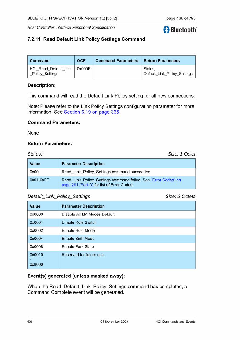
BLUETOOTH SPECIFICATION Version 1.2 [vol 2] page 436 of 790
Host Controller Interface Functional Specification
7.2.11 Read Default Link Policy Settings Command
Description:
This command will read the Default Link Policy setting for all new connections.
Note: Please refer to the Link Policy Settings configuration parameter for more information. See Section 6.19 on page 365.
Command Parameters:
None
Return Parameters:
Status: Size: 1 Octet
Default_Link_Policy_Settings Size: 2 Octets
Event(s) generated (unless masked away):
When the Read_Default_Link_Policy_Settings command has completed, a Command Complete event will be generated.
Command OCF Command Parameters Return Parameters
HCI_Read_Default_Link_Policy_Settings
0x000E Status,Default_Link_Policy_Settings
Value Parameter Description
0x00 Read_Link_Policy_Settings command succeeded
0x01-0xFF Read_Link_Policy_Settings command failed. See “Error Codes” on page 291 [Part D] for list of Error Codes.
Value Parameter Description
0x0000 Disable All LM Modes Default
0x0001 Enable Role Switch
0x0002 Enable Hold Mode
0x0004 Enable Sniff Mode
0x0008 Enable Park State
0x0010-0x8000
Reserved for future use.
436 05 November 2003 HCI Commands and Events
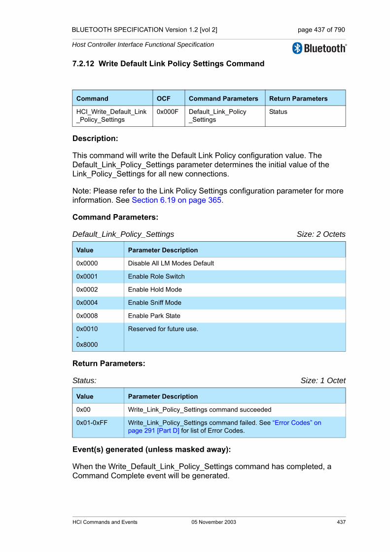
BLUETOOTH SPECIFICATION Version 1.2 [vol 2] page 437 of 790
Host Controller Interface Functional Specification
7.2.12 Write Default Link Policy Settings Command
Description:
This command will write the Default Link Policy configuration value. The Default_Link_Policy_Settings parameter determines the initial value of the Link_Policy_Settings for all new connections.
Note: Please refer to the Link Policy Settings configuration parameter for more information. See Section 6.19 on page 365.
Command Parameters:
Default_Link_Policy_Settings Size: 2 Octets
Return Parameters:
Status: Size: 1 Octet
Event(s) generated (unless masked away):
When the Write_Default_Link_Policy_Settings command has completed, a Command Complete event will be generated.
Command OCF Command Parameters Return Parameters
HCI_Write_Default_Link_Policy_Settings
0x000F Default_Link_Policy_Settings
Status
Value Parameter Description
0x0000 Disable All LM Modes Default
0x0001 Enable Role Switch
0x0002 Enable Hold Mode
0x0004 Enable Sniff Mode
0x0008 Enable Park State
0x0010-0x8000
Reserved for future use.
Value Parameter Description
0x00 Write_Link_Policy_Settings command succeeded
0x01-0xFF Write_Link_Policy_Settings command failed. See “Error Codes” on page 291 [Part D] for list of Error Codes.
HCI Commands and Events 05 November 2003 437

BLUETOOTH SPECIFICATION Version 1.2 [vol 2] page 438 of 790
Host Controller Interface Functional Specification
7.2.13 Flow Specification Command
Description: The Flow_Specification command is used to specify the flow parameters for the traffic carried over the ACL connection identified by the Connection_Handle. The Connection_Handle must be a Connection_Handle for an ACL connection. The Connection_Handle command parameter is used to identify for which connection the Flow Specification is requested. The flow parameters refer to the outgoing or incoming traffic of the ACL link, as indicated by the Flow_direction field. The Flow Specification command allows the Link Manager to have the parameters of the outgoing as well as the incoming flow for the ACL connection. The flow parame-ters are defined in the L2CAP specification “Quality of Service (QoS) Option” on page 60[vol. 3]. The Link Manager will determine if the flow parameters can be supported. Bluetooth devices that are both master and slave can use this com-mand.
Command Parameters:
Connection_Handle: Size: 2 Octets (12 Bits meaningful)
Flags: Size: 1 Octet
Flow_direction: Size: 1 Octet
Command OCF Command Parameters Return Parameters
HCI_Flow_Specification 0x0010 Connection_Handle,Flags,Flow_direction,Service_Type,Token_Rate,Token_Bucket_Size,Peak_Bandwidth,Access Latency
Value Parameter Description
0xXXXX Connection Handle used to identify for which ACL connection the Flow is specified. Range: 0x0000 - 0x0EFF (0x0F00 – 0x0FFF Reserved for future use)
Value Parameter Description
0x00 – 0xFF Reserved for Future Use.
Value Parameter Description
0x00 Outgoing Flow i.e. traffic send over the ACL connection
0x01 Incoming Flow i.e. traffic received over the ACL connection
0x02 – 0xFF Reserved for Future Use.
438 05 November 2003 HCI Commands and Events

BLUETOOTH SPECIFICATION Version 1.2 [vol 2] page 439 of 790
Host Controller Interface Functional Specification
Service_Type: Size: 1 Octet
Token Rate: Size: 4 Octets
Token Bucket Size: Size: 4 Octets
Peak_Bandwidth: Size: 4 Octets
Access Latency: Size: 4 Octets
Return Parameters:
None.
Event(s) generated (unless masked away):
When the Controller receives the Flow Specification command, the Controller sends the Command Status event to the Host. When the Link Manager has determined if the Flow specification can be supported, the Controller on the local Bluetooth device sends a Flow Specification Complete event to the Host. The Flow Specification Complete event returned by the Controller on the local side contains the status of this command, and returned Flow parameters describing the supported QoS for the ACL connection.
Note: No Command Complete event will be sent by the Controller to indicate that this command has been completed. Instead, the Flow Specification Com-plete event will indicate that this command has been completed.
Value Parameter Description
0x00 No Traffic
0x01 Best Effort
0x02 Guaranteed
0x03 – 0xFF Reserved for Future Use
Value Parameter Description
0xXXXXXXXX Token Rate in octets per second
Value Parameter Description
0xXXXXXXXX Token Bucket Size in octets
Value Parameter Description
0xXXXXXXXX Peak Bandwidth in octets per second
Value Parameter Description
0xXXXXXXXX Latency in microseconds
HCI Commands and Events 05 November 2003 439

BLUETOOTH SPECIFICATION Version 1.2 [vol 2] page 440 of 790
Host Controller Interface Functional Specification
7.3 CONTROLLER & BASEBAND COMMANDS
The Controller & Baseband Commands provide access and control to various capabilities of the Bluetooth hardware. These parameters provide control of Bluetooth devices and of the capabilities of the Controller, Link Manager, and Baseband. The host device can use these commands to modify the behavior of the local device. For the HCI Control and Baseband Commands, the OGF is defined as 0x03.
7.3.1 Set Event Mask Command
Description:
The Set_Event_Mask command is used to control which events are generated by the HCI for the Host. If the bit in the Event_Mask is set to a one, then the event associated with that bit will be enabled. The Host has to deal with each event that occurs by the Bluetooth devices. The event mask allows the Host to control how much it is interrupted.Command Parameters:
Event_Mask: Size: 8 Octets
Command OCF Command Parameters Return Parameters
HCI_Set_Event_Mask 0x0001 Event_Mask Status
Value Parameter Description
0x0000000000000000 No events specified
0x0000000000000001 Inquiry Complete Event
0x0000000000000002 Inquiry Result Event
0x0000000000000004 Connection Complete Event
0x0000000000000008 Connection Request Event
0x0000000000000010 Disconnection Complete Event
0x0000000000000020 Authentication Complete Event
0x0000000000000040 Remote Name Request Complete Event
0x0000000000000080 Encryption Change Event
0x0000000000000100 Change Connection Link Key Complete Event
0x0000000000000200 Master Link Key Complete Event
0x0000000000000400 Read Remote Supported Features Complete Event
0x0000000000000800 Read Remote Version Information Complete Event
0x0000000000001000 QoS Setup Complete Event
0x0000000000002000 Reserved
0x0000000000004000 Reserved
0x0000000000008000 Hardware Error Event
440 05 November 2003 HCI Commands and Events

BLUETOOTH SPECIFICATION Version 1.2 [vol 2] page 441 of 790
Host Controller Interface Functional Specification
0x0000000000010000 Flush Occurred Event
0x0000000000020000 Role Change Event
0x0000000000040000 Reserved
0x0000000000080000 Mode Change Event
0x0000000000100000 Return Link Keys Event
0x0000000000200000 PIN Code Request Event
0x0000000000400000 Link Key Request Event
0x0000000000800000 Link Key Notification Event
0x0000000001000000 Loopback Command Event
0x0000000002000000 Data Buffer Overflow Event
0x0000000004000000 Max Slots Change Event
0x0000000008000000 Read Clock Offset Complete Event
0x0000000010000000 Connection Packet Type Changed Event
0x0000000020000000 QoS Violation Event
0x0000000040000000 Page Scan Mode Change Event [deprecated]
0x0000000080000000 Page Scan Repetition Mode Change Event
0x0000000100000000 Flow Specification Complete Event
0x0000000200000000 Inquiry Result with RSSI Event
0x0000000400000000 Read Remote Extended Features Complete Event
0x0000000800000000 Reserved
0x0000001000000000 Reserved
0x0000002000000000 Reserved
0x0000004000000000 Reserved
0x0000008000000000 Reserved
0x0000010000000000 Reserved
0x0000020000000000 Reserved
0x0000040000000000 Reserved
0x0000080000000000 Synchronous Connection Complete Event
0x0000100000000000 Synchronous Connection Changed event
0xFFFFE00000000000 Reserved for future use
0x00001FFFFFFFFFFF Default (All events enabled)
Value Parameter Description
HCI Commands and Events 05 November 2003 441
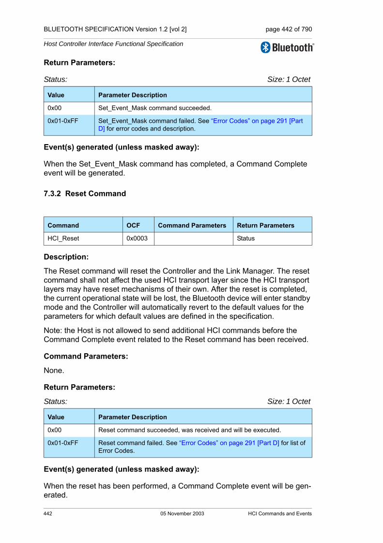
BLUETOOTH SPECIFICATION Version 1.2 [vol 2] page 442 of 790
Host Controller Interface Functional Specification
Return Parameters:
Status: Size: 1 Octet
Event(s) generated (unless masked away):
When the Set_Event_Mask command has completed, a Command Complete event will be generated.
7.3.2 Reset Command
Description:
The Reset command will reset the Controller and the Link Manager. The reset command shall not affect the used HCI transport layer since the HCI transport layers may have reset mechanisms of their own. After the reset is completed, the current operational state will be lost, the Bluetooth device will enter standby mode and the Controller will automatically revert to the default values for the parameters for which default values are defined in the specification.
Note: the Host is not allowed to send additional HCI commands before the Command Complete event related to the Reset command has been received.
Command Parameters:
None.
Return Parameters:
Status: Size: 1 Octet
Event(s) generated (unless masked away):
When the reset has been performed, a Command Complete event will be gen-erated.
Value Parameter Description
0x00 Set_Event_Mask command succeeded.
0x01-0xFF Set_Event_Mask command failed. See “Error Codes” on page 291 [Part D] for error codes and description.
Command OCF Command Parameters Return Parameters
HCI_Reset 0x0003 Status
Value Parameter Description
0x00 Reset command succeeded, was received and will be executed.
0x01-0xFF Reset command failed. See “Error Codes” on page 291 [Part D] for list of Error Codes.
442 05 November 2003 HCI Commands and Events
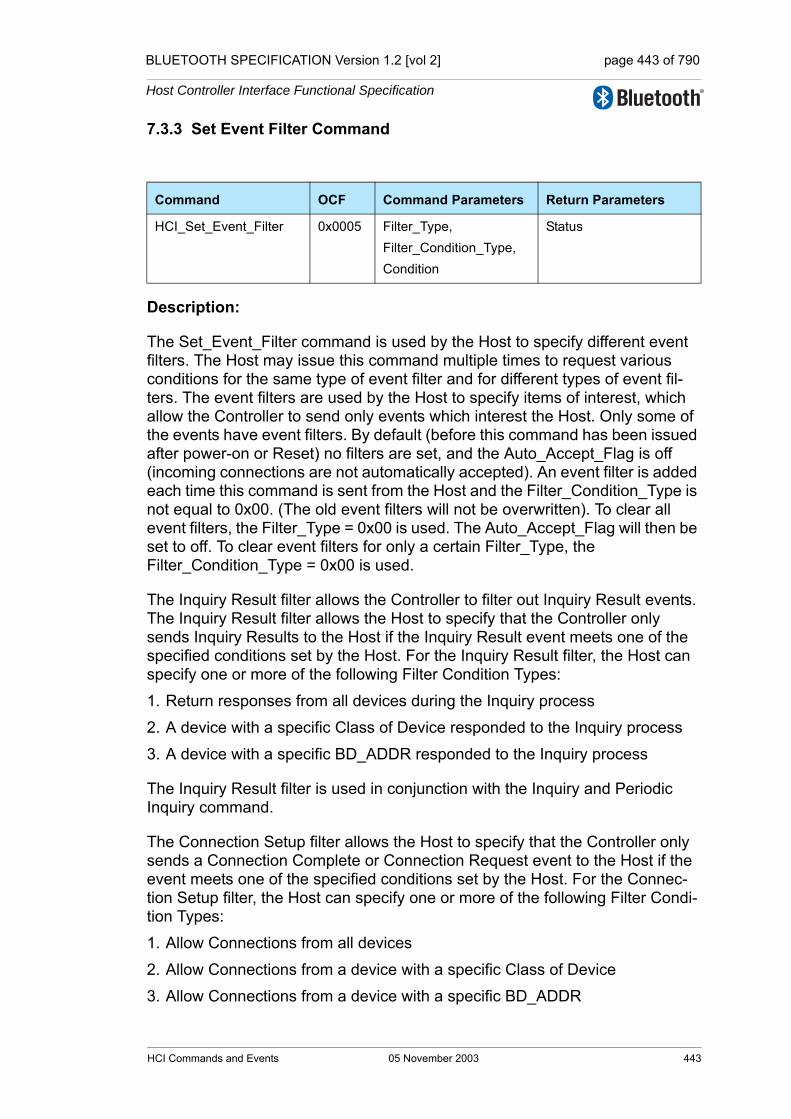
BLUETOOTH SPECIFICATION Version 1.2 [vol 2] page 443 of 790
Host Controller Interface Functional Specification
7.3.3 Set Event Filter Command
Description:
The Set_Event_Filter command is used by the Host to specify different event filters. The Host may issue this command multiple times to request various conditions for the same type of event filter and for different types of event fil-ters. The event filters are used by the Host to specify items of interest, which allow the Controller to send only events which interest the Host. Only some of the events have event filters. By default (before this command has been issued after power-on or Reset) no filters are set, and the Auto_Accept_Flag is off (incoming connections are not automatically accepted). An event filter is added each time this command is sent from the Host and the Filter_Condition_Type is not equal to 0x00. (The old event filters will not be overwritten). To clear all event filters, the Filter_Type = 0x00 is used. The Auto_Accept_Flag will then be set to off. To clear event filters for only a certain Filter_Type, the Filter_Condition_Type = 0x00 is used.
The Inquiry Result filter allows the Controller to filter out Inquiry Result events. The Inquiry Result filter allows the Host to specify that the Controller only sends Inquiry Results to the Host if the Inquiry Result event meets one of the specified conditions set by the Host. For the Inquiry Result filter, the Host can specify one or more of the following Filter Condition Types:
1. Return responses from all devices during the Inquiry process
2. A device with a specific Class of Device responded to the Inquiry process
3. A device with a specific BD_ADDR responded to the Inquiry process
The Inquiry Result filter is used in conjunction with the Inquiry and Periodic Inquiry command.
The Connection Setup filter allows the Host to specify that the Controller only sends a Connection Complete or Connection Request event to the Host if the event meets one of the specified conditions set by the Host. For the Connec-tion Setup filter, the Host can specify one or more of the following Filter Condi-tion Types:
1. Allow Connections from all devices
2. Allow Connections from a device with a specific Class of Device
3. Allow Connections from a device with a specific BD_ADDR
Command OCF Command Parameters Return Parameters
HCI_Set_Event_Filter 0x0005 Filter_Type,Filter_Condition_Type,Condition
Status
HCI Commands and Events 05 November 2003 443

BLUETOOTH SPECIFICATION Version 1.2 [vol 2] page 444 of 790
Host Controller Interface Functional Specification
For each of these conditions, an Auto_Accept_Flag parameter allows the Host to specify what action should be done when the condition is met. The Auto_Accept_Flag allows the Host to specify if the incoming connection should be auto accepted (in which case the Controller will send the Connection Complete event to the Host when the connection is completed) or if the Host should make the decision (in which case the Controller will send the Connection Request event to the Host, to elicit a decision on the connection).
The Connection Setup filter is used in conjunction with the Read/Write_Scan_Enable commands. If the local device is in the process of a page scan, and is paged by another device which meets one on the conditions set by the Host, and the Auto_Accept_Flag is off for this device, then a Connection Request event will be sent to the Host by the Controller. A Connection Com-plete event will be sent later on after the Host has responded to the incoming connection attempt. In this same example, if the Auto_Accept_Flag is on, then a Connection Complete event will be sent to the Host by the Controller. (No Connection Request event will be sent in that case.)
The Controller will store these filters in volatile memory until the Host clears the event filters using the Set_Event_Filter command or until the Reset command is issued. The number of event filters the Controller can store is implementation dependent. If the Host tries to set more filters than the Controller can store, the Controller will return the Memory Full error code and the filter will not be installed.Note: the Clear All Filters has no Filter Condition Types or Conditions. Note: In the condition that a connection is auto accepted, a Link Key Request event and possibly also a PIN Code Request event and a Link Key Notification event could be sent to the Host by the Controller before the Connection Com-plete event is sent.
If there is a contradiction between event filters, the latest set event filter will override older ones. An example is an incoming connection attempt where more than one Connection Setup filter matches the incoming connection attempt, but the Auto-Accept_Flag has different values in the different filters.
Command Parameters:
Filter_Type: Size: 1 Octet
Value Parameter Description
0x00 Clear All Filters (Note: In this case, the Filter_Condition_type and Condi-tion parameters should not be given, they should have a length of 0 octets. Filter_Type should be the only parameter.)
0x01 Inquiry Result.
0x02 Connection Setup.
0x03-0xFF Reserved for Future Use.
444 05 November 2003 HCI Commands and Events
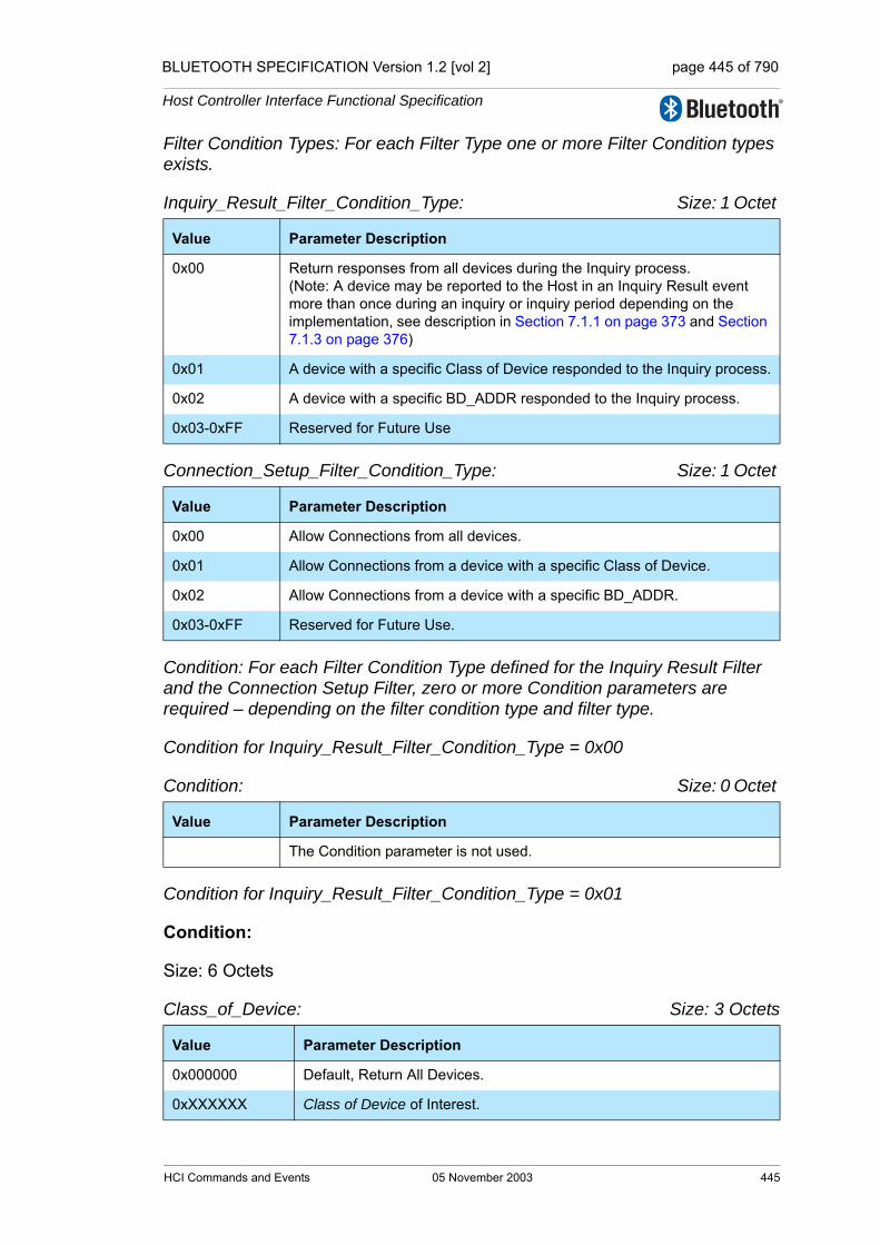
BLUETOOTH SPECIFICATION Version 1.2 [vol 2] page 445 of 790
Host Controller Interface Functional Specification
Filter Condition Types: For each Filter Type one or more Filter Condition types exists.
Inquiry_Result_Filter_Condition_Type: Size: 1 Octet
Connection_Setup_Filter_Condition_Type: Size: 1 Octet
Condition: For each Filter Condition Type defined for the Inquiry Result Filter and the Connection Setup Filter, zero or more Condition parameters are required – depending on the filter condition type and filter type.
Condition for Inquiry_Result_Filter_Condition_Type = 0x00
Condition: Size: 0 Octet
Condition for Inquiry_Result_Filter_Condition_Type = 0x01
Condition:
Size: 6 Octets
Class_of_Device: Size: 3 Octets
Value Parameter Description
0x00 Return responses from all devices during the Inquiry process.(Note: A device may be reported to the Host in an Inquiry Result event more than once during an inquiry or inquiry period depending on the implementation, see description in Section 7.1.1 on page 373 and Section 7.1.3 on page 376)
0x01 A device with a specific Class of Device responded to the Inquiry process.
0x02 A device with a specific BD_ADDR responded to the Inquiry process.
0x03-0xFF Reserved for Future Use
Value Parameter Description
0x00 Allow Connections from all devices.
0x01 Allow Connections from a device with a specific Class of Device.
0x02 Allow Connections from a device with a specific BD_ADDR.
0x03-0xFF Reserved for Future Use.
Value Parameter Description
The Condition parameter is not used.
Value Parameter Description
0x000000 Default, Return All Devices.
0xXXXXXX Class of Device of Interest.
HCI Commands and Events 05 November 2003 445
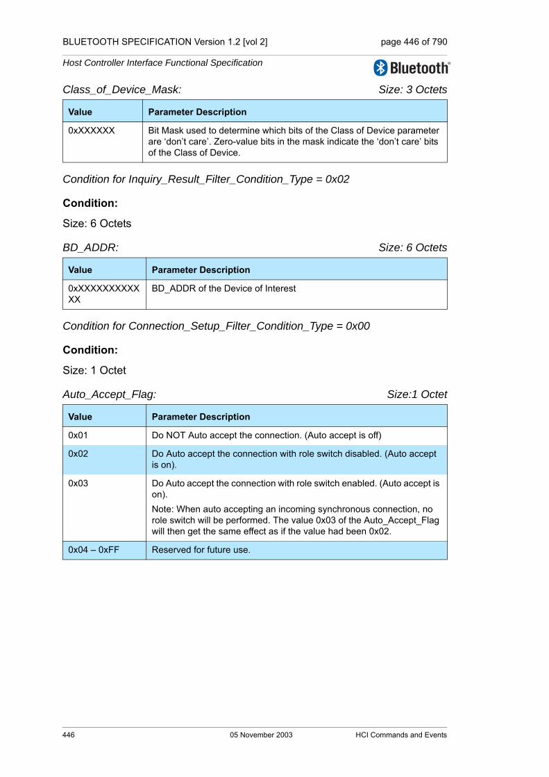
BLUETOOTH SPECIFICATION Version 1.2 [vol 2] page 446 of 790
Host Controller Interface Functional Specification
Class_of_Device_Mask: Size: 3 Octets
Condition for Inquiry_Result_Filter_Condition_Type = 0x02
Condition:
Size: 6 Octets
BD_ADDR: Size: 6 Octets
Condition for Connection_Setup_Filter_Condition_Type = 0x00
Condition:
Size: 1 Octet
Auto_Accept_Flag: Size:1 Octet
Value Parameter Description
0xXXXXXX Bit Mask used to determine which bits of the Class of Device parameter are ‘don’t care’. Zero-value bits in the mask indicate the ‘don’t care’ bits of the Class of Device.
Value Parameter Description
0xXXXXXXXXXXXX
BD_ADDR of the Device of Interest
Value Parameter Description
0x01 Do NOT Auto accept the connection. (Auto accept is off)
0x02 Do Auto accept the connection with role switch disabled. (Auto accept is on).
0x03 Do Auto accept the connection with role switch enabled. (Auto accept is on). Note: When auto accepting an incoming synchronous connection, no role switch will be performed. The value 0x03 of the Auto_Accept_Flag will then get the same effect as if the value had been 0x02.
0x04 – 0xFF Reserved for future use.
446 05 November 2003 HCI Commands and Events
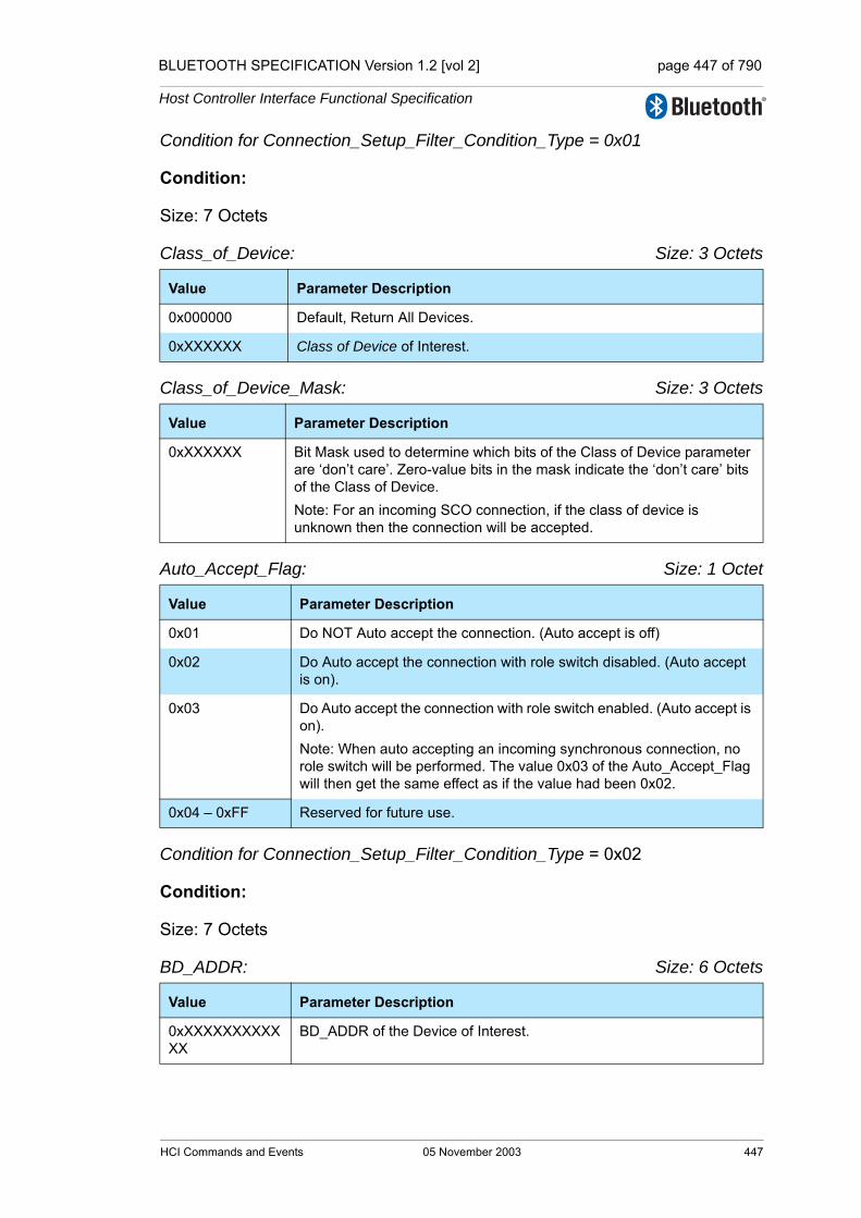
BLUETOOTH SPECIFICATION Version 1.2 [vol 2] page 447 of 790
Host Controller Interface Functional Specification
Condition for Connection_Setup_Filter_Condition_Type = 0x01
Condition:
Size: 7 Octets
Class_of_Device: Size: 3 Octets
Class_of_Device_Mask: Size: 3 Octets
Auto_Accept_Flag: Size: 1 Octet
Condition for Connection_Setup_Filter_Condition_Type = 0x02
Condition:
Size: 7 Octets
BD_ADDR: Size: 6 Octets
Value Parameter Description
0x000000 Default, Return All Devices.
0xXXXXXX Class of Device of Interest.
Value Parameter Description
0xXXXXXX Bit Mask used to determine which bits of the Class of Device parameter are ‘don’t care’. Zero-value bits in the mask indicate the ‘don’t care’ bits of the Class of Device.Note: For an incoming SCO connection, if the class of device is unknown then the connection will be accepted.
Value Parameter Description
0x01 Do NOT Auto accept the connection. (Auto accept is off)
0x02 Do Auto accept the connection with role switch disabled. (Auto accept is on).
0x03 Do Auto accept the connection with role switch enabled. (Auto accept is on). Note: When auto accepting an incoming synchronous connection, no role switch will be performed. The value 0x03 of the Auto_Accept_Flag will then get the same effect as if the value had been 0x02.
0x04 – 0xFF Reserved for future use.
Value Parameter Description
0xXXXXXXXXXXXX
BD_ADDR of the Device of Interest.
HCI Commands and Events 05 November 2003 447

BLUETOOTH SPECIFICATION Version 1.2 [vol 2] page 448 of 790
Host Controller Interface Functional Specification
Auto_Accept_Flag: Size: 1 Octet
Return Parameters:
Status: Size: 1 Octet
Event(s) generated (unless masked away):
A Command Complete event for this command will occur when the Controller has enabled the filtering of events. When one of the conditions are met, a spe-cific event will occur.
7.3.4 Flush Command
Description:
The Flush command is used to discard all data that is currently pending for transmission in the Controller for the specified connection handle, even if there currently are chunks of data that belong to more than one L2CAP packet in the Controller. After this, all data that is sent to the Controller for the same connec-tion handle will be discarded by the Controller until an HCI Data Packet with the start Packet_Boundary_Flag (0x02) is received. When this happens, a new transmission attempt can be made. This command will allow higher-level soft-ware to control how long the baseband should try to retransmit a baseband packet for a connection handle before all data that is currently pending for transmission in the Controller should be flushed. Note that the Flush command
Value Parameter Description
0x01 Do NOT Auto accept the connection. (Auto accept is off)
0x02 Do Auto accept the connection with role switch disabled. (Auto accept is on).
0x03 Do Auto accept the connection with role switch enabled. (Auto accept is on). Note: When auto accepting an incoming synchronous con-nection, no role switch will be performed. The value 0x03 of the Auto_Accept_Flag will then get the same effect as if the value had been 0x02.
0x04 – 0xFF Reserved for future use.
Value Parameter Description
0x00 Set_Event_Filter command succeeded.
0x01-0xFF Set_Event_Filter command failed. See “Error Codes” on page 291 [Part D] for list of Error Codes.
Command OCF Command Parameters Return Parameters
HCI_Flush 0x0008 Connection_Handle Status, Connection_Handle
448 05 November 2003 HCI Commands and Events
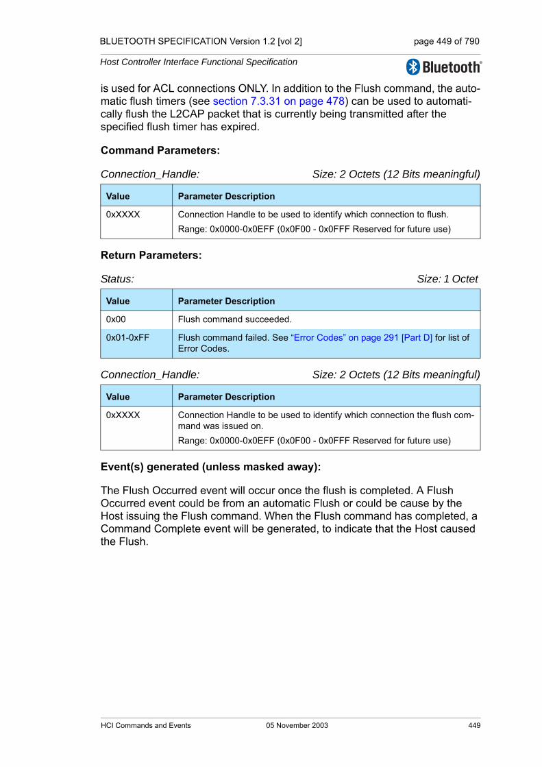
BLUETOOTH SPECIFICATION Version 1.2 [vol 2] page 449 of 790
Host Controller Interface Functional Specification
is used for ACL connections ONLY. In addition to the Flush command, the auto-matic flush timers (see section 7.3.31 on page 478) can be used to automati-cally flush the L2CAP packet that is currently being transmitted after the specified flush timer has expired.
Command Parameters:
Connection_Handle: Size: 2 Octets (12 Bits meaningful)
Return Parameters:
Status: Size: 1 Octet
Connection_Handle: Size: 2 Octets (12 Bits meaningful)
Event(s) generated (unless masked away):
The Flush Occurred event will occur once the flush is completed. A Flush Occurred event could be from an automatic Flush or could be cause by the Host issuing the Flush command. When the Flush command has completed, a Command Complete event will be generated, to indicate that the Host caused the Flush.
Value Parameter Description
0xXXXX Connection Handle to be used to identify which connection to flush.Range: 0x0000-0x0EFF (0x0F00 - 0x0FFF Reserved for future use)
Value Parameter Description
0x00 Flush command succeeded.
0x01-0xFF Flush command failed. See “Error Codes” on page 291 [Part D] for list of Error Codes.
Value Parameter Description
0xXXXX Connection Handle to be used to identify which connection the flush com-mand was issued on.Range: 0x0000-0x0EFF (0x0F00 - 0x0FFF Reserved for future use)
HCI Commands and Events 05 November 2003 449
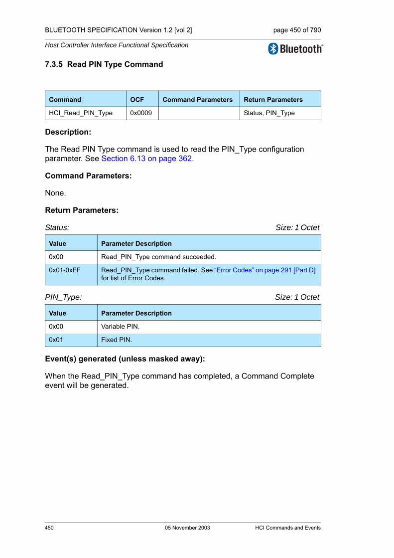
BLUETOOTH SPECIFICATION Version 1.2 [vol 2] page 450 of 790
Host Controller Interface Functional Specification
7.3.5 Read PIN Type Command
Description:
The Read PIN Type command is used to read the PIN_Type configuration parameter. See Section 6.13 on page 362.
Command Parameters:
None.
Return Parameters:
Status: Size: 1 Octet
PIN_Type: Size: 1 Octet
Event(s) generated (unless masked away):
When the Read_PIN_Type command has completed, a Command Complete event will be generated.
Command OCF Command Parameters Return Parameters
HCI_Read_PIN_Type 0x0009 Status, PIN_Type
Value Parameter Description
0x00 Read_PIN_Type command succeeded.
0x01-0xFF Read_PIN_Type command failed. See “Error Codes” on page 291 [Part D] for list of Error Codes.
Value Parameter Description
0x00 Variable PIN.
0x01 Fixed PIN.
450 05 November 2003 HCI Commands and Events
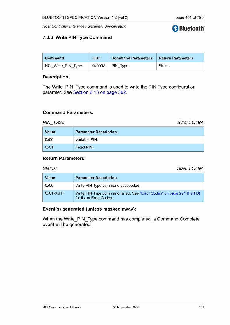
BLUETOOTH SPECIFICATION Version 1.2 [vol 2] page 451 of 790
Host Controller Interface Functional Specification
7.3.6 Write PIN Type Command
Description:
The Write_PIN_Type command is used to write the PIN Type configuration paramter. See Section 6.13 on page 362.
Command Parameters:
PIN_Type: Size: 1 Octet
Return Parameters:
Status: Size: 1 Octet
Event(s) generated (unless masked away):
When the Write_PIN_Type command has completed, a Command Complete event will be generated.
Command OCF Command Parameters Return Parameters
HCI_Write_PIN_Type 0x000A PIN_Type Status
Value Parameter Description
0x00 Variable PIN.
0x01 Fixed PIN.
Value Parameter Description
0x00 Write PIN Type command succeeded.
0x01-0xFF Write PIN Type command failed. See “Error Codes” on page 291 [Part D] for list of Error Codes.
HCI Commands and Events 05 November 2003 451
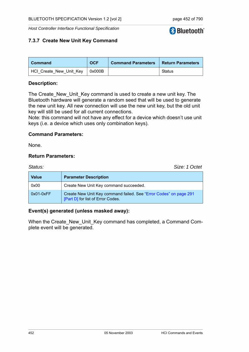
BLUETOOTH SPECIFICATION Version 1.2 [vol 2] page 452 of 790
Host Controller Interface Functional Specification
7.3.7 Create New Unit Key Command
Description:
The Create_New_Unit_Key command is used to create a new unit key. The Bluetooth hardware will generate a random seed that will be used to generate the new unit key. All new connection will use the new unit key, but the old unit key will still be used for all current connections. Note: this command will not have any effect for a device which doesn’t use unit keys (i.e. a device which uses only combination keys).
Command Parameters:
None.
Return Parameters:
Status: Size: 1 Octet
Event(s) generated (unless masked away):
When the Create_New_Unit_Key command has completed, a Command Com-plete event will be generated.
Command OCF Command Parameters Return Parameters
HCI_Create_New_Unit_Key 0x000B Status
Value Parameter Description
0x00 Create New Unit Key command succeeded.
0x01-0xFF Create New Unit Key command failed. See “Error Codes” on page 291 [Part D] for list of Error Codes.
452 05 November 2003 HCI Commands and Events
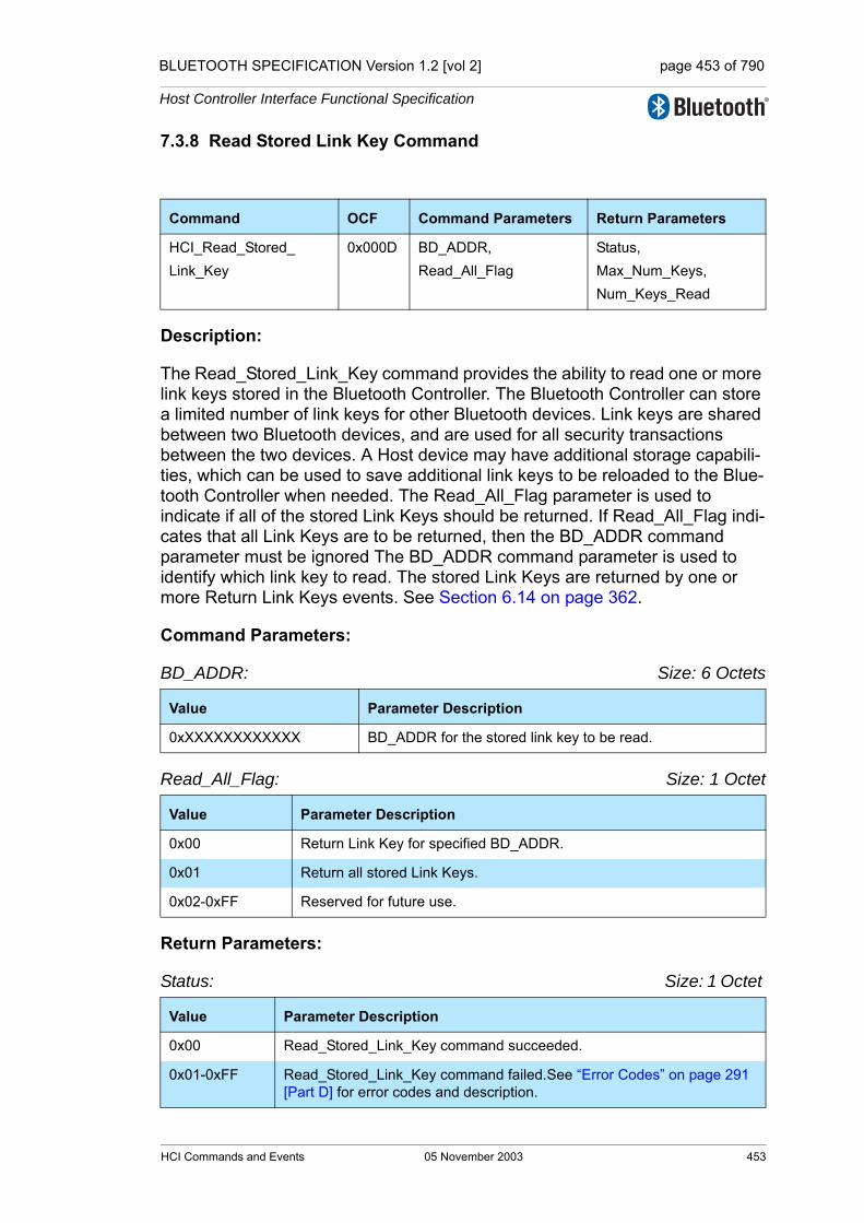
BLUETOOTH SPECIFICATION Version 1.2 [vol 2] page 453 of 790
Host Controller Interface Functional Specification
7.3.8 Read Stored Link Key Command
Description:
The Read_Stored_Link_Key command provides the ability to read one or more link keys stored in the Bluetooth Controller. The Bluetooth Controller can store a limited number of link keys for other Bluetooth devices. Link keys are shared between two Bluetooth devices, and are used for all security transactions between the two devices. A Host device may have additional storage capabili-ties, which can be used to save additional link keys to be reloaded to the Blue-tooth Controller when needed. The Read_All_Flag parameter is used to indicate if all of the stored Link Keys should be returned. If Read_All_Flag indi-cates that all Link Keys are to be returned, then the BD_ADDR command parameter must be ignored The BD_ADDR command parameter is used to identify which link key to read. The stored Link Keys are returned by one or more Return Link Keys events. See Section 6.14 on page 362.
Command Parameters:
BD_ADDR: Size: 6 Octets
Read_All_Flag: Size: 1 Octet
Return Parameters:
Status: Size: 1 Octet
Command OCF Command Parameters Return Parameters
HCI_Read_Stored_Link_Key
0x000D BD_ADDR,Read_All_Flag
Status,Max_Num_Keys,Num_Keys_Read
Value Parameter Description
0xXXXXXXXXXXXX BD_ADDR for the stored link key to be read.
Value Parameter Description
0x00 Return Link Key for specified BD_ADDR.
0x01 Return all stored Link Keys.
0x02-0xFF Reserved for future use.
Value Parameter Description
0x00 Read_Stored_Link_Key command succeeded.
0x01-0xFF Read_Stored_Link_Key command failed.See “Error Codes” on page 291 [Part D] for error codes and description.
HCI Commands and Events 05 November 2003 453

BLUETOOTH SPECIFICATION Version 1.2 [vol 2] page 454 of 790
Host Controller Interface Functional Specification
Max_Num_Keys: Size: 2 Octets
Num_Keys_Read: Size: 2 Octets
Event(s) generated (unless masked away):
Zero or more instances of the Return Link Keys event will occur after the com-mand is issued. When there are no link keys stored, no Return Link Keys events will be returned. When there are link keys stored, the number of link keys returned in each Return Link Keys event is implementation specific. When the Read Stored Link Key command has completed a Command Com-plete event will be generated.
7.3.9 Write Stored Link Key Command
Description:
The Write_Stored_Link_Key command provides the ability to write one or more link keys to be stored in the Bluetooth Controller. The Bluetooth Controller can store a limited number of link keys for other Bluetooth devices. If no additional space is available in the Bluetooth Controller then no additional link keys will be stored. If space is limited and if all the link keys to be stored will not fit in the limited space, then the order of the list of link keys without any error will determine which link keys are stored. Link keys at the beginning of the list will be stored first. The Num_Keys_Written parameter will return the number of link keys that were suc-cessfully stored. If no additional space is available, then the Host must delete one or more stored link keys before any additional link keys are stored. The link key replacement algorithm is implemented by the Host and not the Controller. Link keys are shared between two Bluetooth devices and are used for all security trans-actions between the two devices. A Host device may have additional storage capabilities, which can be used to save additional link keys to be reloaded to the
Value Parameter Description
0xXXXX Total Number of Link Keys that the Controller can store.Range: 0x0000 – 0xFFFF
Value Parameter Description
0xXXXX Number of Link Keys Read.Range: 0x0000 – 0xFFFF
Command OCF Command Parameters Return Parameters
HCI_Write_Stored_Link_Key 0x0011 Num_Keys_To_Write,BD_ADDR[i],Link_Key[i]
Status,Num_Keys_Written
454 05 November 2003 HCI Commands and Events

BLUETOOTH SPECIFICATION Version 1.2 [vol 2] page 455 of 790
Host Controller Interface Functional Specification
Bluetooth Controller when needed. See Section 6.14 on page 362.Note: Link Keys are only stored by issuing this command.
Command Parameters:
Num_Keys_To_Write: Size: 1 Octet
BD_ADDR [i]: Size: 6 Octets * Num_Keys_To_Write
Link_Key: Size: 16 Octets
Return Parameters:
Status: Size: 1 Octet
Num_Keys_Written: Size: 1 Octets
Event(s) generated (unless masked away):
When the Write_Stored_Link_Key command has completed, a Command Complete event will be generated.
Value Parameter Description
0xXX Number of Link Keys to Write.Range: 0x01 - 0x0B
Value Parameter Description
0xXXXXXXXXXXXX BD_ADDR for the associated Link Key.
Value Parameter Description
0xXXXXXXXXXXXXXXXXXXXXXXXXXXXXXXXX
Link Key for an associated BD_ADDR.
Value Parameter Description
0x00 Write_Stored_Link_Key command succeeded.
0x01-0xFF Write_Stored_Link_Key command failed. See “Error Codes” on page 291 [Part D] for list of Error Codes.
Value Parameter Description
0xXX Number of Link Keys successfully written.Range: 0x00 – 0x0B
HCI Commands and Events 05 November 2003 455

BLUETOOTH SPECIFICATION Version 1.2 [vol 2] page 456 of 790
Host Controller Interface Functional Specification
7.3.10 Delete Stored Link Key Command
Description:
The Delete_Stored_Link_Key command provides the ability to remove one or more of the link keys stored in the Bluetooth Controller. The Bluetooth Control-ler can store a limited number of link keys for other Bluetooth devices. Link keys are shared between two Bluetooth devices and are used for all security transactions between the two devices. The Delete_All_Flag parameter is used to indicate if all of the stored Link Keys should be deleted. If the Delete_All_Flag indicates that all Link Keys are to be deleted, then the BD_ADDR command parameter must be ignored This command provides the ability to negate all security agreements between two devices. The BD_ADDR command parameter is used to identify which link key to delete. If a link key is currently in use for a connection, then the link key will be deleted when all of the connections are disconnected. See Section 6.14 on page 362.
Command Parameters:
BD_ADDR: Size: 6 Octets
Delete_All_Flag: Size: 1 Octet
Return Parameters:
Status: Size: 1 Octet
Command OCF Command Parameters Return Parameters
HCI_Delete_Stored_Link_Key
0x0012 BD_ADDR,Delete_All_Flag
Status,Num_Keys_Deleted
Value Parameter Description
0xXXXXXXXXXXXX BD_ADDR for the link key to be deleted.
Value Parameter Description
0x00 Delete only the Link Key for specified BD_ADDR.
0x01 Delete all stored Link Keys.
0x02-0xFF Reserved for future use.
Value Parameter Description
0x00 Delete_Stored_Link_Key command succeeded.
0x01-0xFF Delete_Stored_Link_Key command failed. See “Error Codes” on page 291 [Part D] for error codes and description.
456 05 November 2003 HCI Commands and Events

BLUETOOTH SPECIFICATION Version 1.2 [vol 2] page 457 of 790
Host Controller Interface Functional Specification
Num_Keys_Deleted: Size: 2 Octets
Event(s) generated (unless masked away):
When the Delete_Stored_Link_Key command has completed, a Command Complete event will be generated.
7.3.11 Write Local Name Command
Description:
The Write_Local_Name command provides the ability to modify the user-friendly name for the Bluetooth device. See Section 6.24 on page 368.
Command Parameters:
Local Name: Size: 248 Octets
Return Parameters:
Status: Size: 1 Octet
Event(s) generated (unless masked away):
When the Write_Local_Name command has completed, a Command Com-plete event will be generated.
Value Parameter Description
0xXXXX Number of Link Keys Deleted
Command OCF Command Parameters Return Parameters
HCI_Write_Local_Name 0x0013 Local Name Status
Value Parameter Description
A UTF-8 encoded User-Friendly Descriptive Name for the device.If the name contained in the parameter is shorter than 248 octets, the end of the name is indicated by a NULL octet (0x00), and the following octets (to fill up 248 octets, which is the length of the parameter) do not have valid values.
Null terminated Zero length String. Default.
Value Parameter Description
0x00 Write_Local_Name command succeeded.
0x01-0xFF Write_Local_Name command failed. See “Error Codes” on page 291 [Part D] for list of Error Codes.
HCI Commands and Events 05 November 2003 457
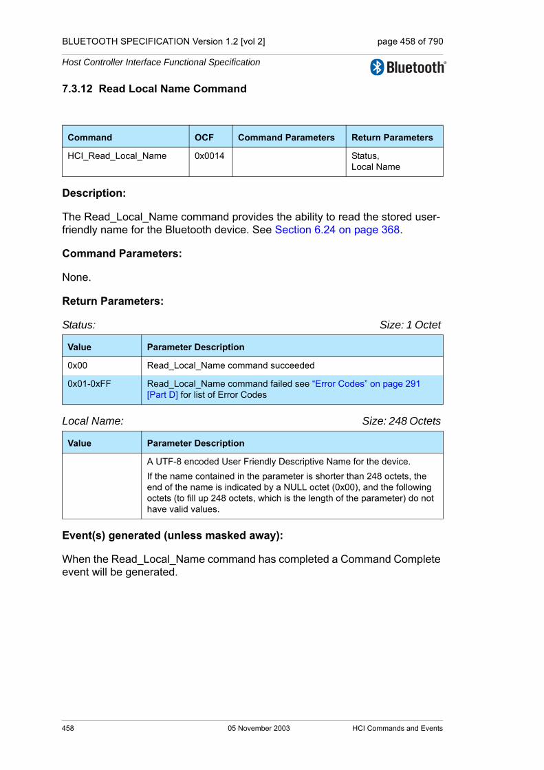
BLUETOOTH SPECIFICATION Version 1.2 [vol 2] page 458 of 790
Host Controller Interface Functional Specification
7.3.12 Read Local Name Command
Description:
The Read_Local_Name command provides the ability to read the stored user-friendly name for the Bluetooth device. See Section 6.24 on page 368.
Command Parameters:
None.
Return Parameters:
Status: Size: 1 Octet
Local Name: Size: 248 Octets
Event(s) generated (unless masked away):
When the Read_Local_Name command has completed a Command Complete event will be generated.
Command OCF Command Parameters Return Parameters
HCI_Read_Local_Name 0x0014 Status, Local Name
Value Parameter Description
0x00 Read_Local_Name command succeeded
0x01-0xFF Read_Local_Name command failed see “Error Codes” on page 291 [Part D] for list of Error Codes
Value Parameter Description
A UTF-8 encoded User Friendly Descriptive Name for the device.If the name contained in the parameter is shorter than 248 octets, the end of the name is indicated by a NULL octet (0x00), and the following octets (to fill up 248 octets, which is the length of the parameter) do not have valid values.
458 05 November 2003 HCI Commands and Events

BLUETOOTH SPECIFICATION Version 1.2 [vol 2] page 459 of 790
Host Controller Interface Functional Specification
7.3.13 Read Connection Accept Timeout Command
Description:
This command will read the value for the Connection_Accept_Timeout configu-ration parameter. See Section 6.7 on page 359.
Command Parameters:
None.
Return Parameters:
Status: Size: 1 Octet
Conn_Accept_Timeout: Size: 2 Octets
Event(s) generated (unless masked away):
When the Read_Connection_Timeout command has completed, a Command Complete event will be generated.
Command OCF Command Parameters Return Parameters
HCI_Read_Connection_Accept_Timeout
0x0015 Status,Conn_Accept_Timeout
Value Parameter Description
0x00 Read_Connection_Accept_Timeout command succeeded.
0x01-0xFF Read_Connection_Accept_Timeout command failed. See “Error Codes” on page 291 [Part D] for list of Error Codes.
Value Parameter Description
N = 0xXXXX Connection Accept Timeout measured in Number of Baseband slots. Interval Length = N * 0.625 msec (1 Baseband slot)Range for N: 0x0001 – 0xB540Time Range: 0.625 msec -29 seconds
HCI Commands and Events 05 November 2003 459
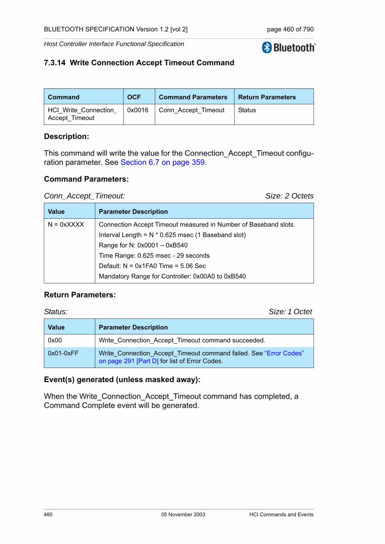
BLUETOOTH SPECIFICATION Version 1.2 [vol 2] page 460 of 790
Host Controller Interface Functional Specification
7.3.14 Write Connection Accept Timeout Command
Description:
This command will write the value for the Connection_Accept_Timeout configu-ration parameter. See Section 6.7 on page 359.
Command Parameters:
Conn_Accept_Timeout: Size: 2 Octets
Return Parameters:
Status: Size: 1 Octet
Event(s) generated (unless masked away):
When the Write_Connection_Accept_Timeout command has completed, a Command Complete event will be generated.
Command OCF Command Parameters Return Parameters
HCI_Write_Connection_Accept_Timeout
0x0016 Conn_Accept_Timeout Status
Value Parameter Description
N = 0xXXXX Connection Accept Timeout measured in Number of Baseband slots. Interval Length = N * 0.625 msec (1 Baseband slot)Range for N: 0x0001 – 0xB540Time Range: 0.625 msec - 29 secondsDefault: N = 0x1FA0 Time = 5.06 SecMandatory Range for Controller: 0x00A0 to 0xB540
Value Parameter Description
0x00 Write_Connection_Accept_Timeout command succeeded.
0x01-0xFF Write_Connection_Accept_Timeout command failed. See “Error Codes” on page 291 [Part D] for list of Error Codes.
460 05 November 2003 HCI Commands and Events

BLUETOOTH SPECIFICATION Version 1.2 [vol 2] page 461 of 790
Host Controller Interface Functional Specification
7.3.15 Read Page Timeout Command
Description:
This command will read the value for the Page_Timeout configuration parame-ter. See Section 6.6 on page 359.
Command Parameters:
None.
Return Parameters:
Status: Size: 1 Octet
Page_Timeout: Size: 2 Octets
Event(s) generated (unless masked away):
When the Read_Page_Timeout command has completed, a Command Com-plete event will be generated.
Command OCF Command Parameters Return Parameters
HCI_Read_Page_Timeout 0x0017 Status,Page_Timeout
Value Parameter Description
0x00 Read_Page_Timeout command succeeded.
0x01-0xFF Read_Page_Timeout command failed. See “Error Codes” on page 291 [Part D] for list of Error Codes.
Value Parameter Description
N = 0xXXXX Page Timeout measured in Number of Baseband slots. Interval Length = N * 0.625 msec (1 Baseband slot)Range for N: 0x0001 – 0xFFFFTime Range: 0.625 msec -40.9 Seconds
HCI Commands and Events 05 November 2003 461

BLUETOOTH SPECIFICATION Version 1.2 [vol 2] page 462 of 790
Host Controller Interface Functional Specification
7.3.16 Write Page Timeout Command
Description:
This command will write the value for the Page_Timeout configuration parame-ter. The Page_Timeout configuration parameter defines the maximum time the local Link Manager will wait for a baseband page response from the remote device at a locally initiated connection attempt. If this time expires and the remote device has not responded to the page at baseband level, the connec-tion attempt will be considered to have failed.
Command Parameters:
Page_Timeout: Size: 2 Octets
Return Parameters:
Status: Size: 1 Octet
Event(s) generated (unless masked away):
When the Write_Page_Timeout command has completed, a Command Com-plete event will be generated.
Command OCF Command Parameters Return Parameters
HCI_Write_Page_Timeout 0x0018 Page_Timeout Status
Value Parameter Description
0 Illegal Page Timeout. Must be larger than 0.
N = 0xXXXX Page Timeout measured in Number of Baseband slots. Interval Length = N * 0.625 msec (1 Baseband slot)Range for N: 0x0001 – 0xFFFFTime Range: 0.625 msec -40.9 Seconds Default: N = 0x2000 Time = 5.12 SecMandatory Range for Controller: 0x0016 to 0xFFFF
Value Parameter Description
0x00 Write_Page_Timeout command succeeded.
0x01-0xFF Write_Page_Timeout command failed. See “Error Codes” on page 291 [Part D] for list of Error Codes.
462 05 November 2003 HCI Commands and Events

BLUETOOTH SPECIFICATION Version 1.2 [vol 2] page 463 of 790
Host Controller Interface Functional Specification
7.3.17 Read Scan Enable Command
Description:
This command will read the value for the Scan_Enable parameter configuration parameter. See Section 6.1 on page 357.
Command Parameters:
None.
Return Parameters:
Status: Size: 1 Octet
Scan_Enable: Size: 1 Octet
Event(s) generated (unless masked away):
When the Read_Scan_Enable command has completed, a Command Com-plete event will be generated.
Command OCF Command Parameters Return Parameters
HCI_Read_Scan_Enable 0x0019 Status, Scan_Enable
Value Parameter Description
0x00 Read_Scan_Enable command succeeded.
0x01-0xFF Read_Scan_Enable command failed. See “Error Codes” on page 291 [Part D] for list of Error Codes.
Value Parameter Description
0x00 No Scans enabled.
0x01 Inquiry Scan enabled.Page Scan disabled.
0x02 Inquiry Scan disabled.Page Scan enabled.
0x03 Inquiry Scan enabled.Page Scan enabled.
0x04-0xFF Reserved
HCI Commands and Events 05 November 2003 463

BLUETOOTH SPECIFICATION Version 1.2 [vol 2] page 464 of 790
Host Controller Interface Functional Specification
7.3.18 Write Scan Enable Command
Description:
This command will write the value for the Scan_Enable configuration parame-ter. See Section 6.1 on page 357.
Command Parameters:
Scan_Enable: Size: 1 Octet
Return Parameters:
Status: Size: 1 Octet
Event(s) generated (unless masked away):
When the Write_Scan_Enable command has completed, a Command Com-plete event will be generated.
Command OCF Command Parameters Return Parameters
HCI_Write_Scan_Enable 0x001A Scan_Enable Status
Value Parameter Description
0x00 No Scans enabled. Default.
0x01 Inquiry Scan enabled.Page Scan disabled.
0x02 Inquiry Scan disabled.Page Scan enabled.
0x03 Inquiry Scan enabled.Page Scan enabled.
0x04-0xFF Reserved
Value Parameter Description
0x00 Write_Scan_Enable command succeeded.
0x01-0xFF Write_Scan_Enable command failed. See “Error Codes” on page 291 [Part D] for list of Error Codes.
464 05 November 2003 HCI Commands and Events
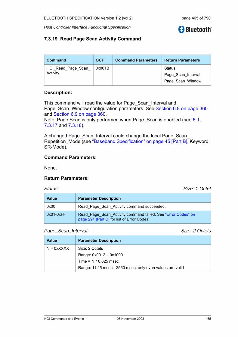
BLUETOOTH SPECIFICATION Version 1.2 [vol 2] page 465 of 790
Host Controller Interface Functional Specification
7.3.19 Read Page Scan Activity Command
Description:
This command will read the value for Page_Scan_Interval and Page_Scan_Window configuration parameters. See Section 6.8 on page 360 and Section 6.9 on page 360.Note: Page Scan is only performed when Page_Scan is enabled (see 6.1, 7.3.17 and 7.3.18).
A changed Page_Scan_Interval could change the local Page_Scan_Repetition_Mode (see “Baseband Specification” on page 45 [Part B], Keyword: SR-Mode).
Command Parameters:
None.
Return Parameters:
Status: Size: 1 Octet
Page_Scan_Interval: Size: 2 Octets
Command OCF Command Parameters Return Parameters
HCI_Read_Page_Scan_Activity
0x001B Status,Page_Scan_Interval,Page_Scan_Window
Value Parameter Description
0x00 Read_Page_Scan_Activity command succeeded.
0x01-0xFF Read_Page_Scan_Activity command failed. See “Error Codes” on page 291 [Part D] for list of Error Codes.
Value Parameter Description
N = 0xXXXX Size: 2 Octets Range: 0x0012 – 0x1000Time = N * 0.625 msec Range: 11.25 msec - 2560 msec; only even values are valid
HCI Commands and Events 05 November 2003 465
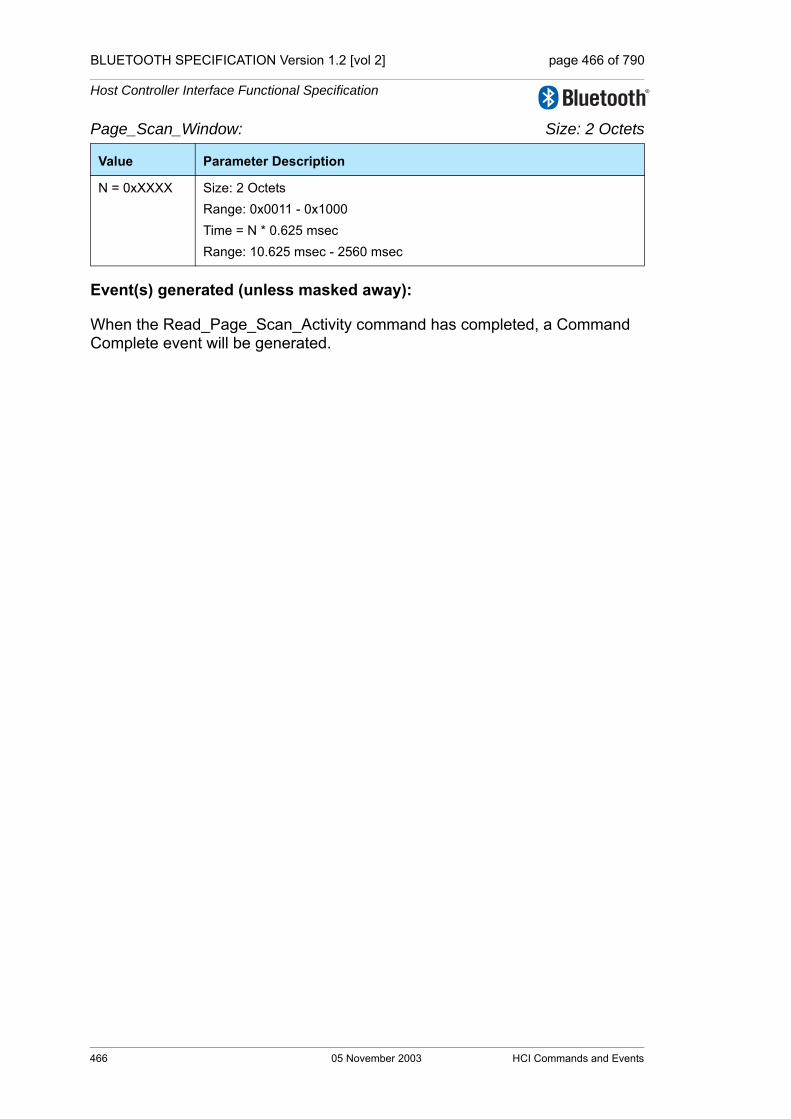
BLUETOOTH SPECIFICATION Version 1.2 [vol 2] page 466 of 790
Host Controller Interface Functional Specification
Page_Scan_Window: Size: 2 Octets
Event(s) generated (unless masked away):
When the Read_Page_Scan_Activity command has completed, a Command Complete event will be generated.
Value Parameter Description
N = 0xXXXX Size: 2 OctetsRange: 0x0011 - 0x1000Time = N * 0.625 msecRange: 10.625 msec - 2560 msec
466 05 November 2003 HCI Commands and Events
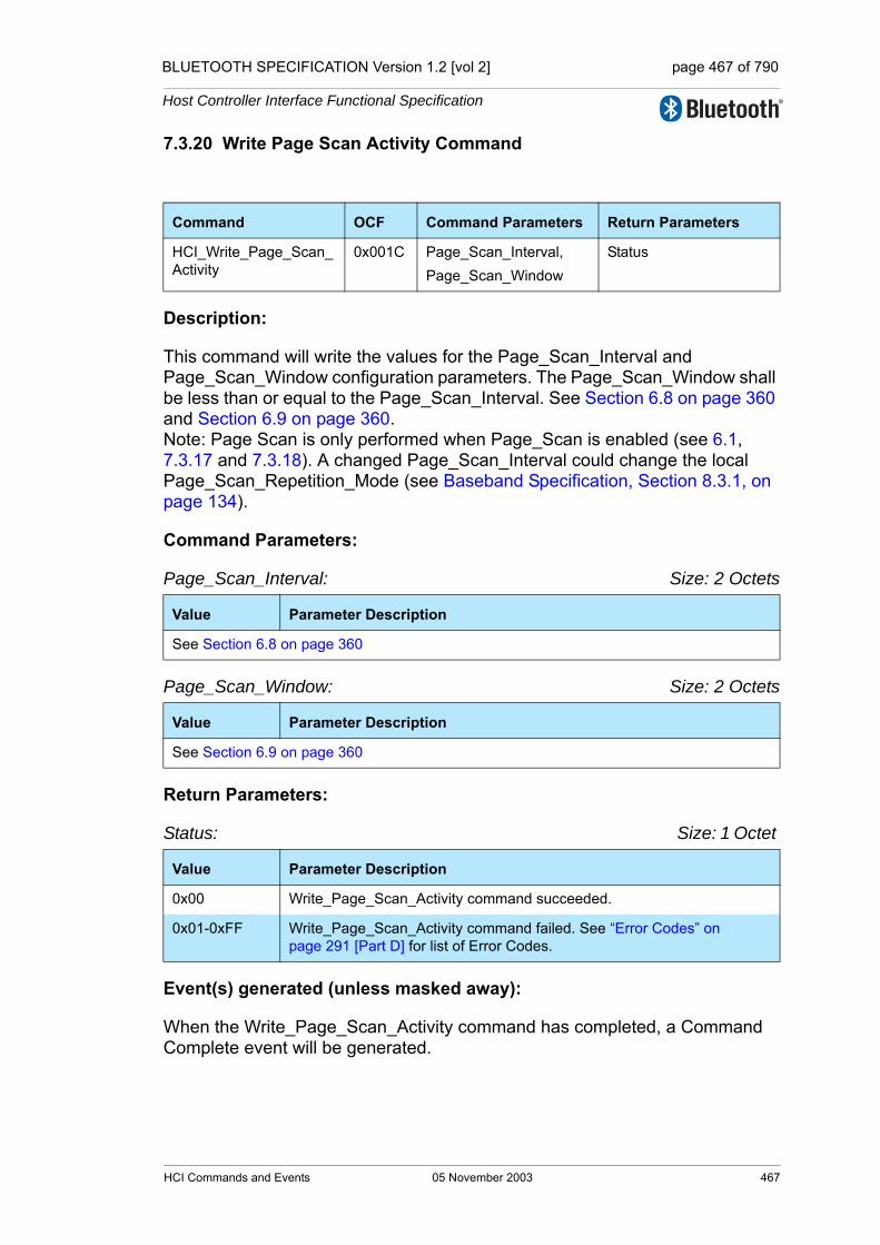
BLUETOOTH SPECIFICATION Version 1.2 [vol 2] page 467 of 790
Host Controller Interface Functional Specification
7.3.20 Write Page Scan Activity Command
Description:
This command will write the values for the Page_Scan_Interval and Page_Scan_Window configuration parameters. The Page_Scan_Window shall be less than or equal to the Page_Scan_Interval. See Section 6.8 on page 360 and Section 6.9 on page 360.Note: Page Scan is only performed when Page_Scan is enabled (see 6.1, 7.3.17 and 7.3.18). A changed Page_Scan_Interval could change the local Page_Scan_Repetition_Mode (see Baseband Specification, Section 8.3.1, on page 134).
Command Parameters:
Page_Scan_Interval: Size: 2 Octets
Page_Scan_Window: Size: 2 Octets
Return Parameters:
Status: Size: 1 Octet
Event(s) generated (unless masked away):
When the Write_Page_Scan_Activity command has completed, a Command Complete event will be generated.
Command OCF Command Parameters Return Parameters
HCI_Write_Page_Scan_Activity
0x001C Page_Scan_Interval,Page_Scan_Window
Status
Value Parameter Description
See Section 6.8 on page 360
Value Parameter Description
See Section 6.9 on page 360
Value Parameter Description
0x00 Write_Page_Scan_Activity command succeeded.
0x01-0xFF Write_Page_Scan_Activity command failed. See “Error Codes” on page 291 [Part D] for list of Error Codes.
HCI Commands and Events 05 November 2003 467
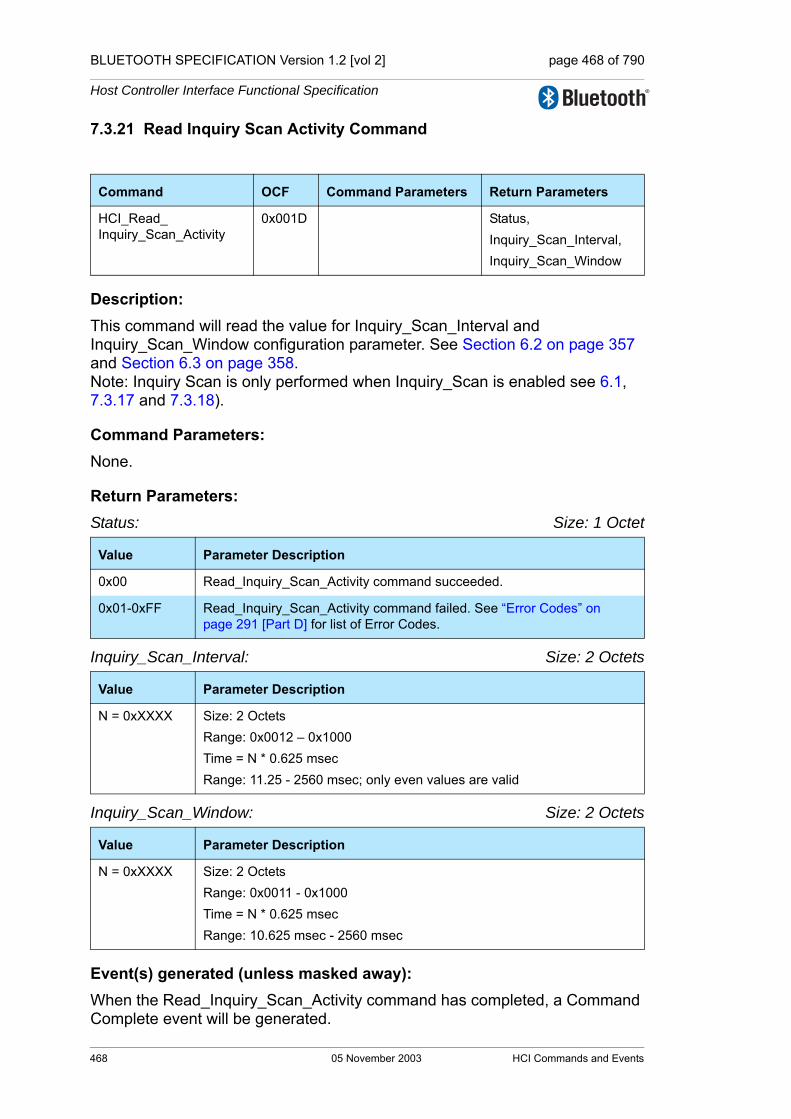
BLUETOOTH SPECIFICATION Version 1.2 [vol 2] page 468 of 790
Host Controller Interface Functional Specification
7.3.21 Read Inquiry Scan Activity Command
Description: This command will read the value for Inquiry_Scan_Interval and Inquiry_Scan_Window configuration parameter. See Section 6.2 on page 357 and Section 6.3 on page 358.Note: Inquiry Scan is only performed when Inquiry_Scan is enabled see 6.1, 7.3.17 and 7.3.18).
Command Parameters: None.
Return Parameters:Status: Size: 1 Octet
Inquiry_Scan_Interval: Size: 2 Octets
Inquiry_Scan_Window: Size: 2 Octets
Event(s) generated (unless masked away): When the Read_Inquiry_Scan_Activity command has completed, a Command Complete event will be generated.
Command OCF Command Parameters Return Parameters
HCI_Read_Inquiry_Scan_Activity
0x001D Status,Inquiry_Scan_Interval,Inquiry_Scan_Window
Value Parameter Description
0x00 Read_Inquiry_Scan_Activity command succeeded.
0x01-0xFF Read_Inquiry_Scan_Activity command failed. See “Error Codes” on page 291 [Part D] for list of Error Codes.
Value Parameter Description
N = 0xXXXX Size: 2 OctetsRange: 0x0012 – 0x1000Time = N * 0.625 msecRange: 11.25 - 2560 msec; only even values are valid
Value Parameter Description
N = 0xXXXX Size: 2 OctetsRange: 0x0011 - 0x1000Time = N * 0.625 msecRange: 10.625 msec - 2560 msec
468 05 November 2003 HCI Commands and Events

BLUETOOTH SPECIFICATION Version 1.2 [vol 2] page 469 of 790
Host Controller Interface Functional Specification
7.3.22 Write Inquiry Scan Activity Command
Description:
This command will write the values for the Inquiry_Scan_Interval and Inquiry_Scan_Window configuration parameters. The Inquiry_Scan_Window shall be less than or equal to the Inquiry_Scan_Interval. See Section 6.2 on page 357 and Section 6.3 on page 358.Note: Inquiry Scan is only performed when Inquiry_Scan is enabled (see 6.1, 7.3.17 and 7.3.18).
Command Parameters:
Inquiry_Scan_Interval: Size: 2 Octets
Inquiry_Scan_Window: Size: 2 Octets
Return Parameters:
Status: Size: 1 Octet
Event(s) generated (unless masked away):
When the Write_Inquiry_Scan_Activity command has completed, a Command Complete event will be generated.
Command OCF Command Parameters Return Parameters
HCI_Write_Inquiry_Scan_Activity
0x001E Inquiry_Scan_Interval,Inquiry_Scan_Window
Status
Value Parameter Description
See Section 6.2 on page 357.
Value Parameter Description
See Section 6.3 on page 358.
Value Parameter Description
0x00 Write_Inquiry_Scan_Activity command succeeded.
0x01-0xFF Write_Inquiry_Scan_Activity command failed. See “Error Codes” on page 291 [Part D] for list of Error Codes.
HCI Commands and Events 05 November 2003 469
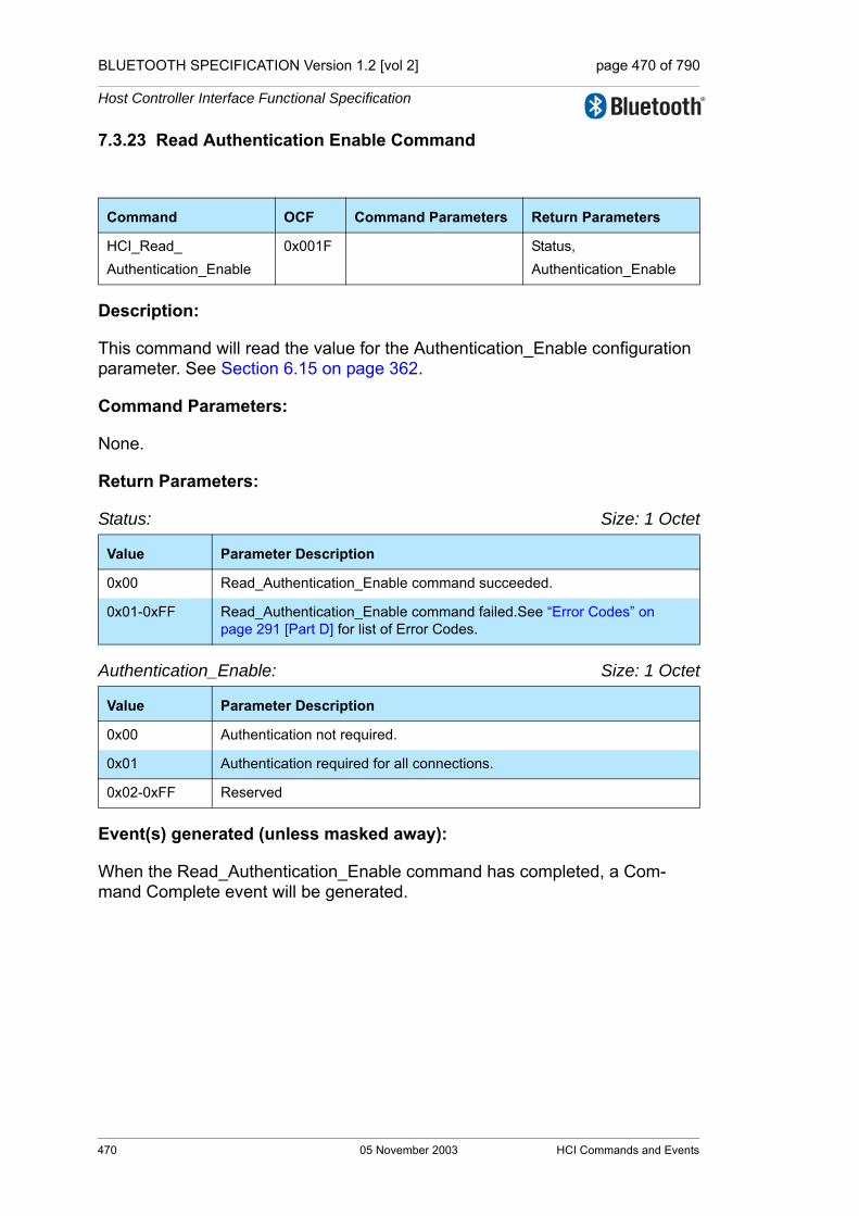
BLUETOOTH SPECIFICATION Version 1.2 [vol 2] page 470 of 790
Host Controller Interface Functional Specification
7.3.23 Read Authentication Enable Command
Description:
This command will read the value for the Authentication_Enable configuration parameter. See Section 6.15 on page 362.
Command Parameters:
None.
Return Parameters:
Status: Size: 1 Octet
Authentication_Enable: Size: 1 Octet
Event(s) generated (unless masked away):
When the Read_Authentication_Enable command has completed, a Com-mand Complete event will be generated.
Command OCF Command Parameters Return Parameters
HCI_Read_Authentication_Enable
0x001F Status,Authentication_Enable
Value Parameter Description
0x00 Read_Authentication_Enable command succeeded.
0x01-0xFF Read_Authentication_Enable command failed.See “Error Codes” on page 291 [Part D] for list of Error Codes.
Value Parameter Description
0x00 Authentication not required.
0x01 Authentication required for all connections.
0x02-0xFF Reserved
470 05 November 2003 HCI Commands and Events
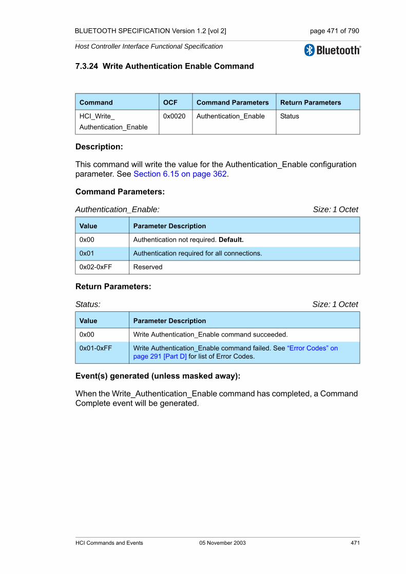
BLUETOOTH SPECIFICATION Version 1.2 [vol 2] page 471 of 790
Host Controller Interface Functional Specification
7.3.24 Write Authentication Enable Command
Description:
This command will write the value for the Authentication_Enable configuration parameter. See Section 6.15 on page 362.
Command Parameters:
Authentication_Enable: Size: 1 Octet
Return Parameters:
Status: Size: 1 Octet
Event(s) generated (unless masked away):
When the Write_Authentication_Enable command has completed, a Command Complete event will be generated.
Command OCF Command Parameters Return Parameters
HCI_Write_Authentication_Enable
0x0020 Authentication_Enable Status
Value Parameter Description
0x00 Authentication not required. Default.
0x01 Authentication required for all connections.
0x02-0xFF Reserved
Value Parameter Description
0x00 Write Authentication_Enable command succeeded.
0x01-0xFF Write Authentication_Enable command failed. See “Error Codes” on page 291 [Part D] for list of Error Codes.
HCI Commands and Events 05 November 2003 471
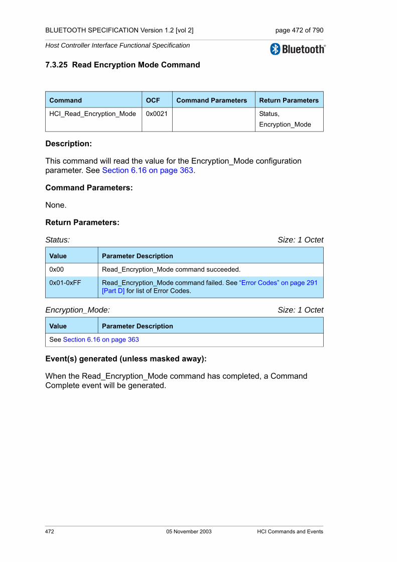
BLUETOOTH SPECIFICATION Version 1.2 [vol 2] page 472 of 790
Host Controller Interface Functional Specification
7.3.25 Read Encryption Mode Command
Description:
This command will read the value for the Encryption_Mode configuration parameter. See Section 6.16 on page 363.
Command Parameters:
None.
Return Parameters:
Status: Size: 1 Octet
Encryption_Mode: Size: 1 Octet
Event(s) generated (unless masked away):
When the Read_Encryption_Mode command has completed, a Command Complete event will be generated.
Command OCF Command Parameters Return Parameters
HCI_Read_Encryption_Mode 0x0021 Status,Encryption_Mode
Value Parameter Description
0x00 Read_Encryption_Mode command succeeded.
0x01-0xFF Read_Encryption_Mode command failed. See “Error Codes” on page 291 [Part D] for list of Error Codes.
Value Parameter Description
See Section 6.16 on page 363
472 05 November 2003 HCI Commands and Events

BLUETOOTH SPECIFICATION Version 1.2 [vol 2] page 473 of 790
Host Controller Interface Functional Specification
7.3.26 Write Encryption Mode Command
Description:
This command will write the value for the Encryption_Mode configuration parameter. See Section 6.16 on page 363.
Command Parameters:
Encryption_Mode: Size: 1 Octet
Return Parameters:
Status: Size: 1 Octet
Event(s) generated (unless masked away):
When the Write_Encryption_Mode command has completed, a Command Complete event will be generated.
Command OCF Command Parameters Return Parameters
HCI_Write_Encryption_Mode 0x0022 Encryption_Mode Status
Value Parameter Description
See Section 6.16 on page 363.
Value Parameter Description
0x00 Write_Encryption_Mode command succeeded.
0x01-0xFF Write_Encryption_Mode command failed. See “Error Codes” on page 291 [Part D] for list of Error Codes.
HCI Commands and Events 05 November 2003 473

BLUETOOTH SPECIFICATION Version 1.2 [vol 2] page 474 of 790
Host Controller Interface Functional Specification
7.3.27 Read Class of Device Command
Description:
This command will read the value for the Class_of_Device parameter. See Section 6.25 on page 368.
Command Parameters:
None.
Return Parameters:
Status: Size: 1 Octet
Class_of_Device: Size: 3 Octets
Event(s) generated (unless masked away):
When the Read_Class_of_Device command has completed, a Command Complete event will be generated.
Command OCF Command Parameters Return Parameters
HCI_Read_Class_of_Device 0x0023 Status,Class_of_Device
Value Parameter Description
0x00 Read_Class_of_Device command succeeded.
0x01-0xFF Read_Class_of_Device command failed. See “Error Codes” on page 291 [Part D] for list of Error Codes.
Value Parameter Description
0xXXXXXX Class of Device for the device.
474 05 November 2003 HCI Commands and Events

BLUETOOTH SPECIFICATION Version 1.2 [vol 2] page 475 of 790
Host Controller Interface Functional Specification
7.3.28 Write Class of Device Command
Description:
This command will write the value for the Class_of_Device parameter. See Section 6.25 on page 368.
Command Parameters:
Class_of_Device: Size: 3 Octets
Return Parameters:
Status: Size: 1 Octet
Event(s) generated (unless masked away):
When the Write_Class_of_Device command has completed, a Command Complete event will be generated.
Command OCF Command Parameters Return Parameters
HCI_Write_Class_of_Device 0x0024 Class_of_Device Status
Value Parameter Description
0xXXXXXX Class of Device for the device.
Value Parameter Description
0x00 Write_Class_of_Device command succeeded.
0x01-0xFF Write_Class_of_Device command failed. See “Error Codes” on page 291 [Part D] for list of Error Codes.
HCI Commands and Events 05 November 2003 475
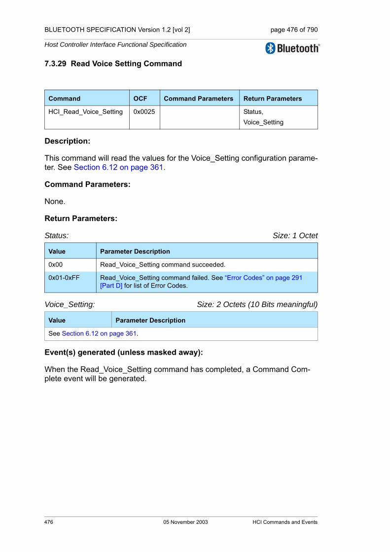
BLUETOOTH SPECIFICATION Version 1.2 [vol 2] page 476 of 790
Host Controller Interface Functional Specification
7.3.29 Read Voice Setting Command
Description:
This command will read the values for the Voice_Setting configuration parame-ter. See Section 6.12 on page 361.
Command Parameters:
None.
Return Parameters:
Status: Size: 1 Octet
Voice_Setting: Size: 2 Octets (10 Bits meaningful)
Event(s) generated (unless masked away):
When the Read_Voice_Setting command has completed, a Command Com-plete event will be generated.
Command OCF Command Parameters Return Parameters
HCI_Read_Voice_Setting 0x0025 Status,Voice_Setting
Value Parameter Description
0x00 Read_Voice_Setting command succeeded.
0x01-0xFF Read_Voice_Setting command failed. See “Error Codes” on page 291 [Part D] for list of Error Codes.
Value Parameter Description
See Section 6.12 on page 361.
476 05 November 2003 HCI Commands and Events
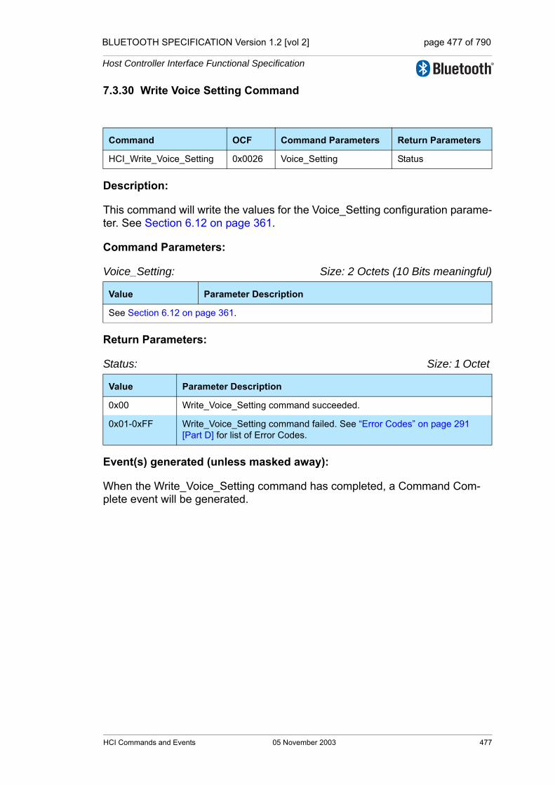
BLUETOOTH SPECIFICATION Version 1.2 [vol 2] page 477 of 790
Host Controller Interface Functional Specification
7.3.30 Write Voice Setting Command
Description:
This command will write the values for the Voice_Setting configuration parame-ter. See Section 6.12 on page 361.
Command Parameters:
Voice_Setting: Size: 2 Octets (10 Bits meaningful)
Return Parameters:
Status: Size: 1 Octet
Event(s) generated (unless masked away):
When the Write_Voice_Setting command has completed, a Command Com-plete event will be generated.
Command OCF Command Parameters Return Parameters
HCI_Write_Voice_Setting 0x0026 Voice_Setting Status
Value Parameter Description
See Section 6.12 on page 361.
Value Parameter Description
0x00 Write_Voice_Setting command succeeded.
0x01-0xFF Write_Voice_Setting command failed. See “Error Codes” on page 291 [Part D] for list of Error Codes.
HCI Commands and Events 05 November 2003 477

BLUETOOTH SPECIFICATION Version 1.2 [vol 2] page 478 of 790
Host Controller Interface Functional Specification
7.3.31 Read Automatic Flush Timeout Command
Description: This command will read the value for the Flush_Timeout parameter for the specified connection handle. See Section 6.20 on page 366.
Command Parameters: Connection_Handle: Size: 2 Octets (12 Bits meaningful)
Return Parameters:Status: Size: 1 Octet
Connection_Handle: Size: 2 Octets (12 Bits meaningful)
Flush_Timeout: Size: 2 Octets
Event(s) generated (unless masked away): When the Read_Automatic_Flush_Timeout command has completed, a Command Complete event will be generated.
Command OCF Command Parameters Return Parameters
HCI_Read_Automatic_Flush_Timeout
0x0027 Connection_Handle Status,Connection_Handle,Flush_Timeout
Value Parameter Description
0xXXXX Specifies which Connection Handle’s Flush Timeout to read.Range: 0x0000-0x0EFF (0x0F00 - 0x0FFF Reserved for future use)
Value Parameter Description
0x00 Read_Automatic_Flush_Timeout command succeeded.
0x01-0xFF Read_Automatic_Flush_Timeout command failed. See “Error Codes” on page 291 [Part D] for list of Error Codes.
Value Parameter Description
0xXXXX Specifies which Connection Handle’s Flush Timeout has been read.Range: 0x0000-0x0EFF (0x0F00 - 0x0FFF Reserved for future use)
Value Parameter Description
0 Timeout = ∞; No Automatic Flush
N = 0xXXXX Flush Timeout = N * 0.625 msecSize: 11 bits Range: 0x0001 – 0x07FF
478 05 November 2003 HCI Commands and Events
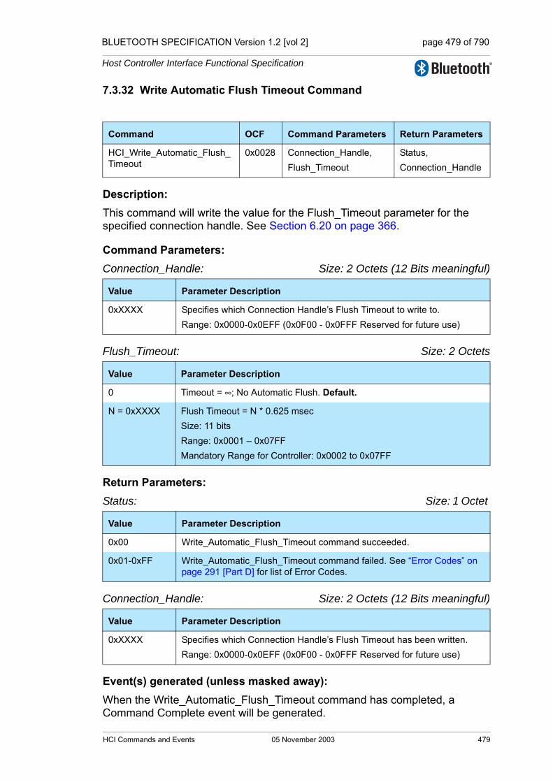
BLUETOOTH SPECIFICATION Version 1.2 [vol 2] page 479 of 790
Host Controller Interface Functional Specification
7.3.32 Write Automatic Flush Timeout Command
Description: This command will write the value for the Flush_Timeout parameter for the specified connection handle. See Section 6.20 on page 366.
Command Parameters: Connection_Handle: Size: 2 Octets (12 Bits meaningful)
Flush_Timeout: Size: 2 Octets
Return Parameters:Status: Size: 1 Octet
Connection_Handle: Size: 2 Octets (12 Bits meaningful)
Event(s) generated (unless masked away): When the Write_Automatic_Flush_Timeout command has completed, a Command Complete event will be generated.
Command OCF Command Parameters Return Parameters
HCI_Write_Automatic_Flush_Timeout
0x0028 Connection_Handle,Flush_Timeout
Status,Connection_Handle
Value Parameter Description
0xXXXX Specifies which Connection Handle’s Flush Timeout to write to.Range: 0x0000-0x0EFF (0x0F00 - 0x0FFF Reserved for future use)
Value Parameter Description
0 Timeout = ∞; No Automatic Flush. Default.
N = 0xXXXX Flush Timeout = N * 0.625 msec Size: 11 bits Range: 0x0001 – 0x07FF Mandatory Range for Controller: 0x0002 to 0x07FF
Value Parameter Description
0x00 Write_Automatic_Flush_Timeout command succeeded.
0x01-0xFF Write_Automatic_Flush_Timeout command failed. See “Error Codes” on page 291 [Part D] for list of Error Codes.
Value Parameter Description
0xXXXX Specifies which Connection Handle’s Flush Timeout has been written.Range: 0x0000-0x0EFF (0x0F00 - 0x0FFF Reserved for future use)
HCI Commands and Events 05 November 2003 479
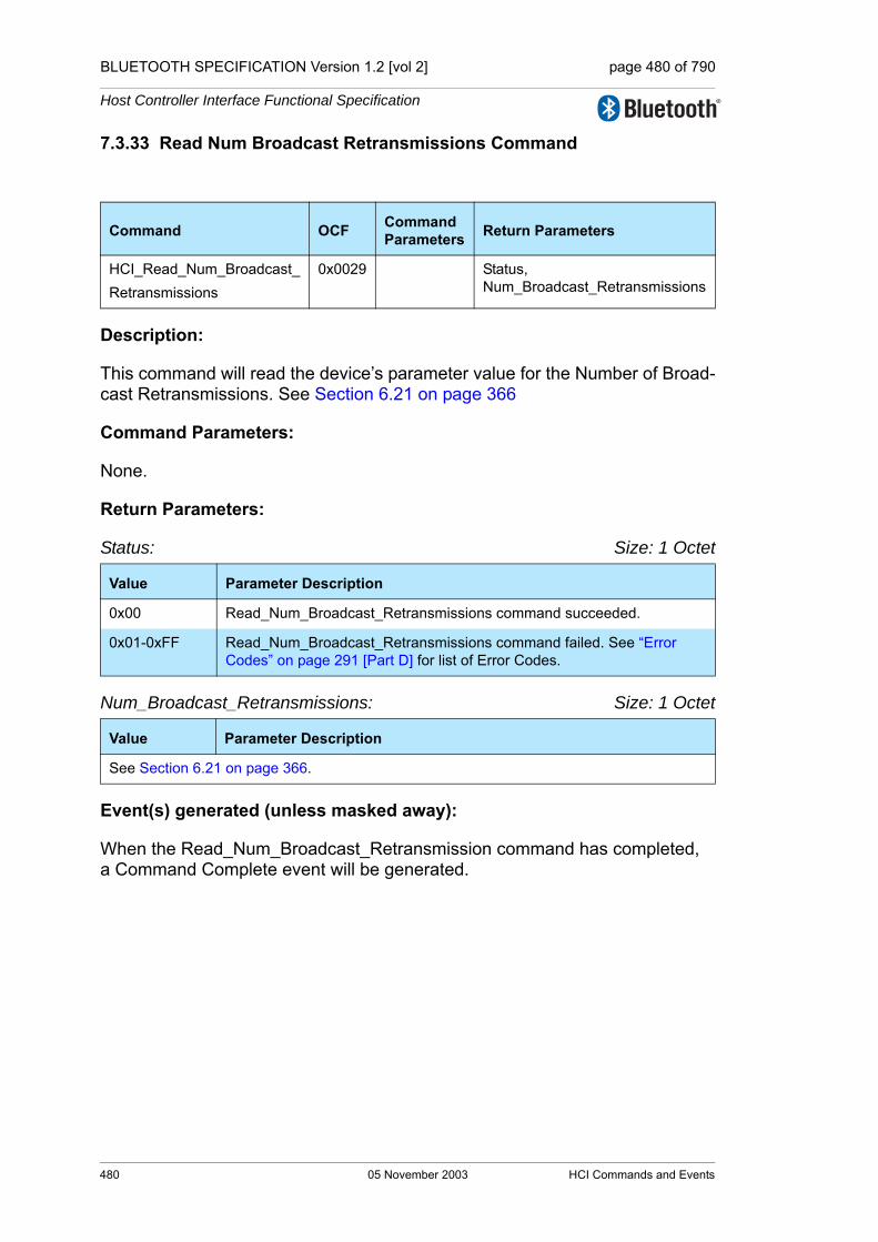
BLUETOOTH SPECIFICATION Version 1.2 [vol 2] page 480 of 790
Host Controller Interface Functional Specification
7.3.33 Read Num Broadcast Retransmissions Command
Description:
This command will read the device’s parameter value for the Number of Broad-cast Retransmissions. See Section 6.21 on page 366
Command Parameters:
None.
Return Parameters:
Status: Size: 1 Octet
Num_Broadcast_Retransmissions: Size: 1 Octet
Event(s) generated (unless masked away):
When the Read_Num_Broadcast_Retransmission command has completed, a Command Complete event will be generated.
Command OCF Command Parameters Return Parameters
HCI_Read_Num_Broadcast_Retransmissions
0x0029 Status, Num_Broadcast_Retransmissions
Value Parameter Description
0x00 Read_Num_Broadcast_Retransmissions command succeeded.
0x01-0xFF Read_Num_Broadcast_Retransmissions command failed. See “Error Codes” on page 291 [Part D] for list of Error Codes.
Value Parameter Description
See Section 6.21 on page 366.
480 05 November 2003 HCI Commands and Events

BLUETOOTH SPECIFICATION Version 1.2 [vol 2] page 481 of 790
Host Controller Interface Functional Specification
7.3.34 Write Num Broadcast Retransmissions Command
Description:
This command will write the device’s parameter value for the Number of Broad-cast Retransmissions. See Section 6.21 on page 366.
Command Parameters:
Num_Broadcast_Retransmissions: Size: 1 Octet
Return Parameters:
Status: Size: 1 Octet
Event(s) generated (unless masked away):
When the Write_Num_Broadcast_Retransmissions command has completed, a Command Complete event will be generated.
Command OCF Command Parameters Return Parameters
HCI_Write_Num_Broadcast_Retransmissions
0x002A Num_Broadcast_Retransmissions
Status
Value Parameter Description
See Section 6.21 on page 366.
Value Parameter Description
0x00 Write_Num_Broadcast_Retransmissions command succeeded.
0x01-0xFF Write_Num_Broadcast_Retransmissions command failed. See “Error Codes” on page 291 [Part D] for list of Error Codes.
HCI Commands and Events 05 November 2003 481
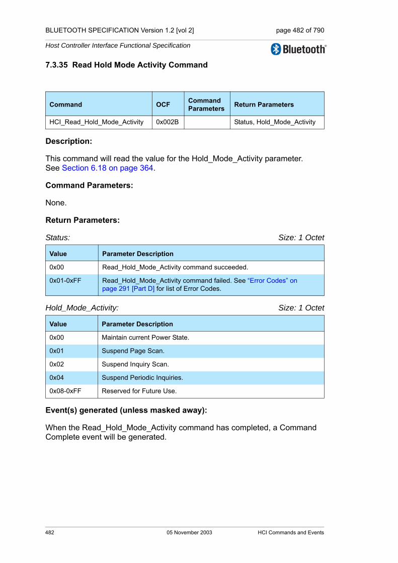
BLUETOOTH SPECIFICATION Version 1.2 [vol 2] page 482 of 790
Host Controller Interface Functional Specification
7.3.35 Read Hold Mode Activity Command
Description:
This command will read the value for the Hold_Mode_Activity parameter. See Section 6.18 on page 364.
Command Parameters:
None.
Return Parameters:
Status: Size: 1 Octet
Hold_Mode_Activity: Size: 1 Octet
Event(s) generated (unless masked away):
When the Read_Hold_Mode_Activity command has completed, a Command Complete event will be generated.
Command OCF Command Parameters Return Parameters
HCI_Read_Hold_Mode_Activity 0x002B Status, Hold_Mode_Activity
Value Parameter Description
0x00 Read_Hold_Mode_Activity command succeeded.
0x01-0xFF Read_Hold_Mode_Activity command failed. See “Error Codes” on page 291 [Part D] for list of Error Codes.
Value Parameter Description
0x00 Maintain current Power State.
0x01 Suspend Page Scan.
0x02 Suspend Inquiry Scan.
0x04 Suspend Periodic Inquiries.
0x08-0xFF Reserved for Future Use.
482 05 November 2003 HCI Commands and Events

BLUETOOTH SPECIFICATION Version 1.2 [vol 2] page 483 of 790
Host Controller Interface Functional Specification
7.3.36 Write Hold Mode Activity Command
Description: This command will write the value for the Hold_Mode_Activity parameter. See Section 6.18 on page 364.
Command Parameters: Hold_Mode_Activity: Size: 1 Octet
Return Parameters:Status: Size: 1 Octet
Event(s) generated (unless masked away): When the Write_Hold_Mode_Activity command has completed, a Command Complete event will be generated.
Command OCF Command Parameters
Return Parameters
HCI_Write_Hold_Mode_Activity 0x002C Hold_Mode_Activity Status
Value Parameter Description
0x00 Maintain current Power State. Default.
0x01 Suspend Page Scan.
0x02 Suspend Inquiry Scan.
0x04 Suspend Periodic Inquiries.
0x08-0xFF Reserved for Future Use.
Value Parameter Description
0x00 Write_Hold_Mode_Activity command succeeded.
0x01-0xFF Write_Hold_Mode_Activity command failed. See “Error Codes” on page 291 [Part D] for list of Error Codes.
HCI Commands and Events 05 November 2003 483

BLUETOOTH SPECIFICATION Version 1.2 [vol 2] page 484 of 790
Host Controller Interface Functional Specification
7.3.37 Read Transmit Power Level Command
Description:
This command will read the values for the Transmit_Power_Level parameter for the specified Connection Handle. The Connection_Handle must be a Connection_Handle for an ACL connection.
Command Parameters:
Connection_Handle: Size: 2 Octets (12 Bits meaningful)
Type: Size: 1 Octet
Return Parameters:
Status: Size: 1 Octet
Connection_Handle: Size: 2 Octets (12 Bits meaningful)
Command OCF Command Parameters Return Parameters
HCI_Read_Transmit_Power_Level
0x002D Connection_Handle,Type
Status,Connection_Handle,Transmit_Power_Level
Value Parameter Description
0xXXXX Specifies which Connection Handle’s Transmit Power Level setting to read.Range: 0x0000-0x0EFF (0x0F00 - 0x0FFF Reserved for future use)
Value Parameter Description
0x00 Read Current Transmit Power Level.
0x01 Read Maximum Transmit Power Level.
0x02-0xFF Reserved
Value Parameter Description
0x00 Read_Transmit_Power_Level command succeeded.
0x01-0xFF Read_Transmit_Power_Level command failed. See “Error Codes” on page 291 [Part D] for list of Error Codes.
Value Parameter Description
0xXXXX Specifies which Connection Handle’s Transmit Power Level setting is returned.Range: 0x0000-0x0EFF (0x0F00 - 0x0FFF Reserved for future use)
484 05 November 2003 HCI Commands and Events

BLUETOOTH SPECIFICATION Version 1.2 [vol 2] page 485 of 790
Host Controller Interface Functional Specification
Transmit_Power_Level: Size: 1 Octet
Event(s) generated (unless masked away):
When the Read_Transmit_Power_Level command has completed, a Com-mand Complete event will be generated.
Value Parameter Description
N = 0xXX Size: 1 Octet (signed integer)
Range: -30 ≤ N ≤ 20
Units: dBm
HCI Commands and Events 05 November 2003 485

BLUETOOTH SPECIFICATION Version 1.2 [vol 2] page 486 of 790
Host Controller Interface Functional Specification
7.3.38 Read Synchronous Flow Control Enable Command
Description:
The Read_Synchronous_Flow_Control_Enable command provides the ability to read the Synchronous_Flow_Control_Enable setting. See Section 6.23 on page 367.Note: the Synchronous_Flow_Control_Enable setting can only be changed if no connections exist.
Command Parameters:
None.
Return Parameters:
Status: Size: 1 Octet
Synchronous_Flow_Control_Enable: Size: 1 Octet
Event(s) generated (unless masked away):
When the Read_Synchronous_Flow_Control_Enable command has com-pleted a Command Complete event will be generated.
Command OCF Command Parameters Return Parameters
HCI_Read_Synchronous_Flow_Control_Enable
0x002E Status, Synchronous_Flow_Control_Enable
Value Parameter Description
0x00 Read_Synchronous_Flow_Control_Enable command succeeded
0x01-0xFF Read_Synchronous_Flow_Control_Enable command failed see “Error Codes” on page 291 [Part D] for list of Error Codes
Value Parameter Description
0x00 Synchronous Flow Control is disabled. No Number of Completed Packets events will be sent from the Controller for Synchronous Connection Han-dles.
0x01 Synchronous Flow Control is enabled. Number of Completed Packets events will be sent from the Controller for Synchronous Connection Han-dles.
486 05 November 2003 HCI Commands and Events
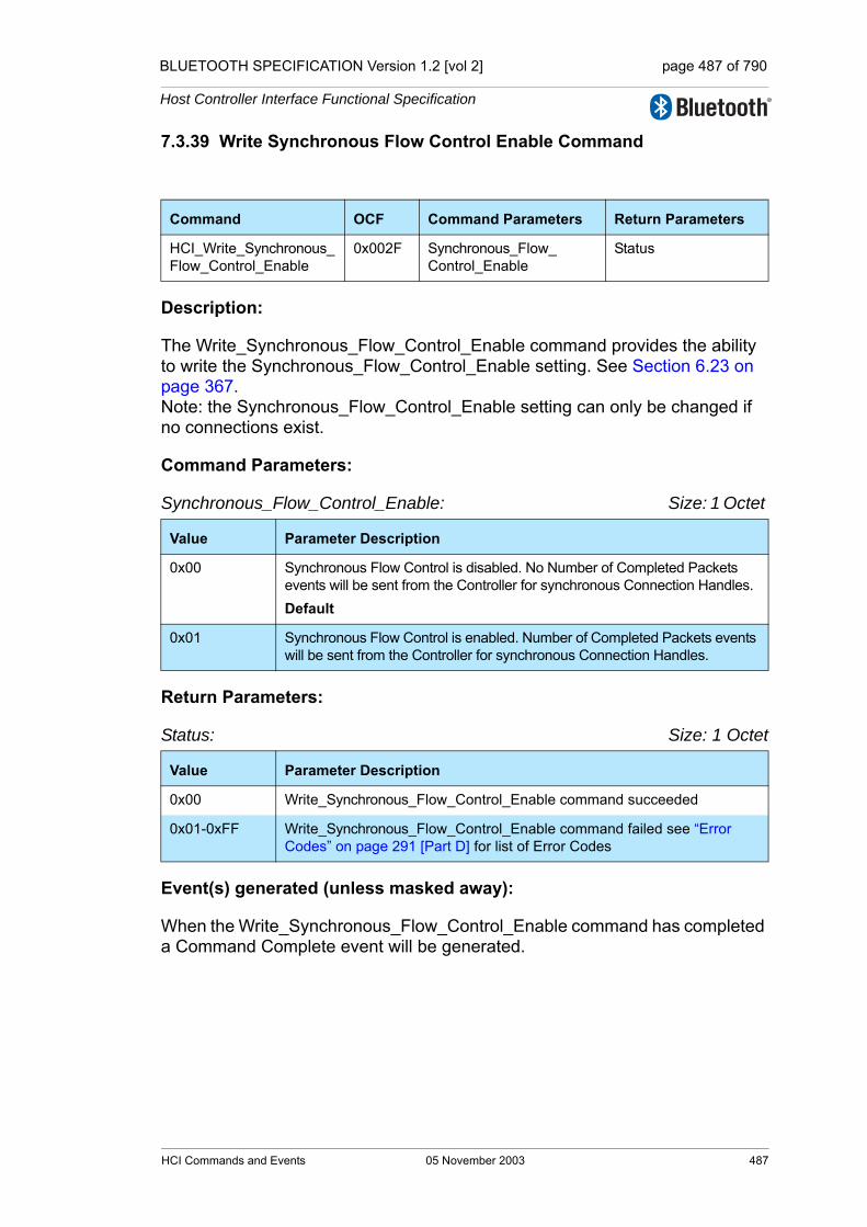
BLUETOOTH SPECIFICATION Version 1.2 [vol 2] page 487 of 790
Host Controller Interface Functional Specification
7.3.39 Write Synchronous Flow Control Enable Command
Description:
The Write_Synchronous_Flow_Control_Enable command provides the ability to write the Synchronous_Flow_Control_Enable setting. See Section 6.23 on page 367. Note: the Synchronous_Flow_Control_Enable setting can only be changed if no connections exist.
Command Parameters:
Synchronous_Flow_Control_Enable: Size: 1 Octet
Return Parameters:
Status: Size: 1 Octet
Event(s) generated (unless masked away):
When the Write_Synchronous_Flow_Control_Enable command has completed a Command Complete event will be generated.
Command OCF Command Parameters Return Parameters
HCI_Write_Synchronous_Flow_Control_Enable
0x002F Synchronous_Flow_Control_Enable
Status
Value Parameter Description
0x00 Synchronous Flow Control is disabled. No Number of Completed Packets events will be sent from the Controller for synchronous Connection Handles.Default
0x01 Synchronous Flow Control is enabled. Number of Completed Packets events will be sent from the Controller for synchronous Connection Handles.
Value Parameter Description
0x00 Write_Synchronous_Flow_Control_Enable command succeeded
0x01-0xFF Write_Synchronous_Flow_Control_Enable command failed see “Error Codes” on page 291 [Part D] for list of Error Codes
HCI Commands and Events 05 November 2003 487

BLUETOOTH SPECIFICATION Version 1.2 [vol 2] page 488 of 790
Host Controller Interface Functional Specification
7.3.40 Set Controller To Host Flow Control Command
Description:This command is used by the Host to turn flow control on or off for data and/or voice sent in the direction from the Controller to the Host. If flow control is turned off, the Host should not send the Host_Number_Of_Completed_Packets com-mand. That command will be ignored by the Controller if it is sent by the Host and flow control is off. If flow control is turned on for HCI ACL Data Packets and off for HCI synchronous Data Packets, Host_Number_Of_Completed_Packets commands sent by the Host should only contain Connection Handles for ACL connections. If flow control is turned off for HCI ACL Data Packets and on for HCI synchronous Data Packets, Host_Number_Of_Completed_Packets commands sent by the Host should only contain Connection Handles for synchronous con-nections. If flow control is turned on for HCI ACL Data Packets and HCI synchro-nous Data Packets, the Host will send Host_Number_Of_Completed_Packets commands both for ACL connections and synchronous connections.The Flow_Control_Enable setting shall only be changed if no connections exist.
Command Parameters: Flow_Control_Enable: Size: 1 Octet
Return Parameters:Status: Size: 1 Octet
Event(s) generated (unless masked away): When the Set_Controller_To_Host_Flow_Control command has completed, a Command Complete event will be generated.
Command OCF Command Parameters Return Parameters
HCI_Set_Controller_To_Host_Flow_Control
0x0031 Flow_Control_Enable Status
Value Parameter Description
0x00 Flow control off in direction from Controller to Host. Default.
0x01 Flow control on for HCI ACL Data Packets and off for HCI synchronous Data Packets in direction from Controller to Host.
0x02 Flow control off for HCI ACL Data Packets and on for HCI synchronous Data Packets in direction from Controller to Host.
0x03 Flow control on both for HCI ACL Data Packets and HCI synchronous Data Packets in direction from Controller to Host.
0x04-0xFF Reserved
Value Parameter Description
0x00 Set_Controller_To_Host_Flow_Control command succeeded.
0x01-0xFF Set_Controller_To_Host_Flow_Control command failed. See “Error Codes” on page 291 [Part D] for list of Error Codes.
488 05 November 2003 HCI Commands and Events
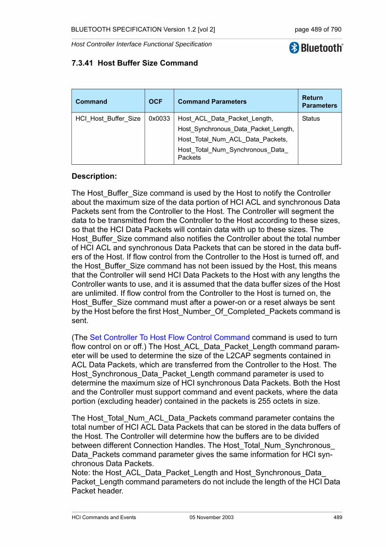
BLUETOOTH SPECIFICATION Version 1.2 [vol 2] page 489 of 790
Host Controller Interface Functional Specification
7.3.41 Host Buffer Size Command
Description:
The Host_Buffer_Size command is used by the Host to notify the Controller about the maximum size of the data portion of HCI ACL and synchronous Data Packets sent from the Controller to the Host. The Controller will segment the data to be transmitted from the Controller to the Host according to these sizes, so that the HCI Data Packets will contain data with up to these sizes. The Host_Buffer_Size command also notifies the Controller about the total number of HCI ACL and synchronous Data Packets that can be stored in the data buff-ers of the Host. If flow control from the Controller to the Host is turned off, and the Host_Buffer_Size command has not been issued by the Host, this means that the Controller will send HCI Data Packets to the Host with any lengths the Controller wants to use, and it is assumed that the data buffer sizes of the Host are unlimited. If flow control from the Controller to the Host is turned on, the Host_Buffer_Size command must after a power-on or a reset always be sent by the Host before the first Host_Number_Of_Completed_Packets command is sent.
(The Set Controller To Host Flow Control Command command is used to turn flow control on or off.) The Host_ACL_Data_Packet_Length command param-eter will be used to determine the size of the L2CAP segments contained in ACL Data Packets, which are transferred from the Controller to the Host. The Host_Synchronous_Data_Packet_Length command parameter is used to determine the maximum size of HCI synchronous Data Packets. Both the Host and the Controller must support command and event packets, where the data portion (excluding header) contained in the packets is 255 octets in size.
The Host_Total_Num_ACL_Data_Packets command parameter contains the total number of HCI ACL Data Packets that can be stored in the data buffers of the Host. The Controller will determine how the buffers are to be divided between different Connection Handles. The Host_Total_Num_Synchronous_Data_Packets command parameter gives the same information for HCI syn-chronous Data Packets. Note: the Host_ACL_Data_Packet_Length and Host_Synchronous_Data_Packet_Length command parameters do not include the length of the HCI Data Packet header.
Command OCF Command Parameters Return Parameters
HCI_Host_Buffer_Size 0x0033 Host_ACL_Data_Packet_Length,Host_Synchronous_Data_Packet_Length,Host_Total_Num_ACL_Data_Packets,Host_Total_Num_Synchronous_Data_Packets
Status
HCI Commands and Events 05 November 2003 489
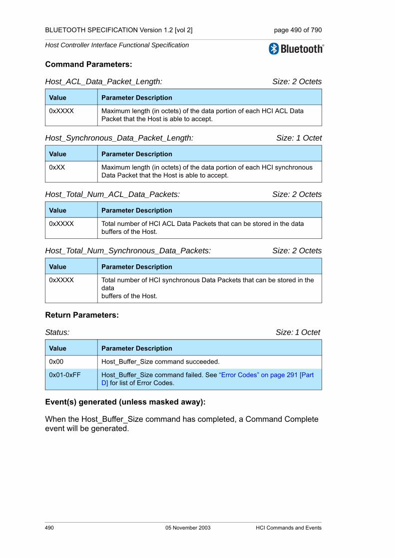
BLUETOOTH SPECIFICATION Version 1.2 [vol 2] page 490 of 790
Host Controller Interface Functional Specification
Command Parameters:
Host_ACL_Data_Packet_Length: Size: 2 Octets
Host_Synchronous_Data_Packet_Length: Size: 1 Octet
Host_Total_Num_ACL_Data_Packets: Size: 2 Octets
Host_Total_Num_Synchronous_Data_Packets: Size: 2 Octets
Return Parameters:
Status: Size: 1 Octet
Event(s) generated (unless masked away):
When the Host_Buffer_Size command has completed, a Command Complete event will be generated.
Value Parameter Description
0xXXXX Maximum length (in octets) of the data portion of each HCI ACL Data Packet that the Host is able to accept.
Value Parameter Description
0xXX Maximum length (in octets) of the data portion of each HCI synchronous Data Packet that the Host is able to accept.
Value Parameter Description
0xXXXX Total number of HCI ACL Data Packets that can be stored in the data buffers of the Host.
Value Parameter Description
0xXXXX Total number of HCI synchronous Data Packets that can be stored in the data buffers of the Host.
Value Parameter Description
0x00 Host_Buffer_Size command succeeded.
0x01-0xFF Host_Buffer_Size command failed. See “Error Codes” on page 291 [Part D] for list of Error Codes.
490 05 November 2003 HCI Commands and Events

BLUETOOTH SPECIFICATION Version 1.2 [vol 2] page 491 of 790
Host Controller Interface Functional Specification
7.3.42 Host Number Of Completed Packets Command
Description:
The Host_Number_Of_Completed_Packets command is used by the Host to indicate to the Controller the number of HCI Data Packets that have been com-pleted for each Connection Handle since the previous Host_Number_Of_Completed_Packetscommand was sent to the Controller. This means that the corresponding buffer space has been freed in the Host. Based on this informa-tion, and the Host_Total_Num_ACL_Data_Packets and Host_Total_Num_Synchronous_Data_Packets command parameters of the Host_Buffer_Size command, the Controller can determine for which Connection Handles the fol-lowing HCI Data Packets should be sent to the Host. The command should only be issued by the Host if flow control in the direction from the Controller to the Host is on and there is at least one connection, or if the Controller is in local loopback mode. Otherwise, the command will be ignored by the Controller. When the Host has completed one or more HCI Data Packet(s) it shall send a Host_Number_Of_Completed_Packets command to the Controller, until it finally reports that all pending HCI Data Packets have been completed. The frequency at which this command is sent is manufacturer specific.
(The Set Controller To Host Flow Control Command command is used to turn flow control on or off.) If flow control from the Controller to the Host is turned on, the Host_Buffer_Size command must after a power-on or a reset always be sent by the Host before the first Host_Number_Of_Completed_Packets com-mand is sent. Note: the Host_Number_Of_Completed_Packets command is a special com-mand in the sense that no event is normally generated after the command has completed. The command may be sent at any time by the Host when there is at least one connection, or if the Controller is in local loopback mode independent of other commands. The normal flow control for commands is not used for the Host_Number_Of_Completed_Packets command.
Command OCF Command Parameters Return Parameters
HCI_Host_Number_Of_Completed_Packets
0x0035 Number_Of_Handles, Connection_Handle[i],Host_Num_Of_Completed_Packets [i]
HCI Commands and Events 05 November 2003 491

BLUETOOTH SPECIFICATION Version 1.2 [vol 2] page 492 of 790
Host Controller Interface Functional Specification
Command Parameters:
Number_Of_Handles: Size: 1 Octet
Connection_Handle[i]: Size: Number_Of_Handles*2 Octets (12 Bits meaning-ful)
Host_Num_Of_Completed_Packets [i]: Size: Number_Of_Handles * 2 Octets
Return Parameters:
None.
Event(s) generated (unless masked away):
Normally, no event is generated after the Host_Number_Of_Completed_Packets command has completed. However, if the Host_Number_Of_Completed_Packets command contains one or more invalid parameters, the Controller will return a Command Complete event with a failure status indicat-ing the Invalid HCI Command Parameters error code. The Host may send the Host_Number_Of_Completed_Packets command at any time when there is at least one connection, or if the Controller is in local loopback mode. The normal flow control for commands is not used for this command.
Value Parameter Description
0xXX The number of Connection Handles and Host_Num_Of_Completed_Packets parameters pairs contained in this command.Range: 0-255
Value Parameter Description
0xXXXX Connection Handle Range: 0x0000-0x0EFF (0x0F00 - 0x0FFF Reserved for future use)
Value Parameter Description
N = 0xXXXX The number of HCI Data Packets that have been completed for the asso-ciated Connection Handle since the previous time the event was returned.Range for N: 0x0000-0xFFFF
492 05 November 2003 HCI Commands and Events
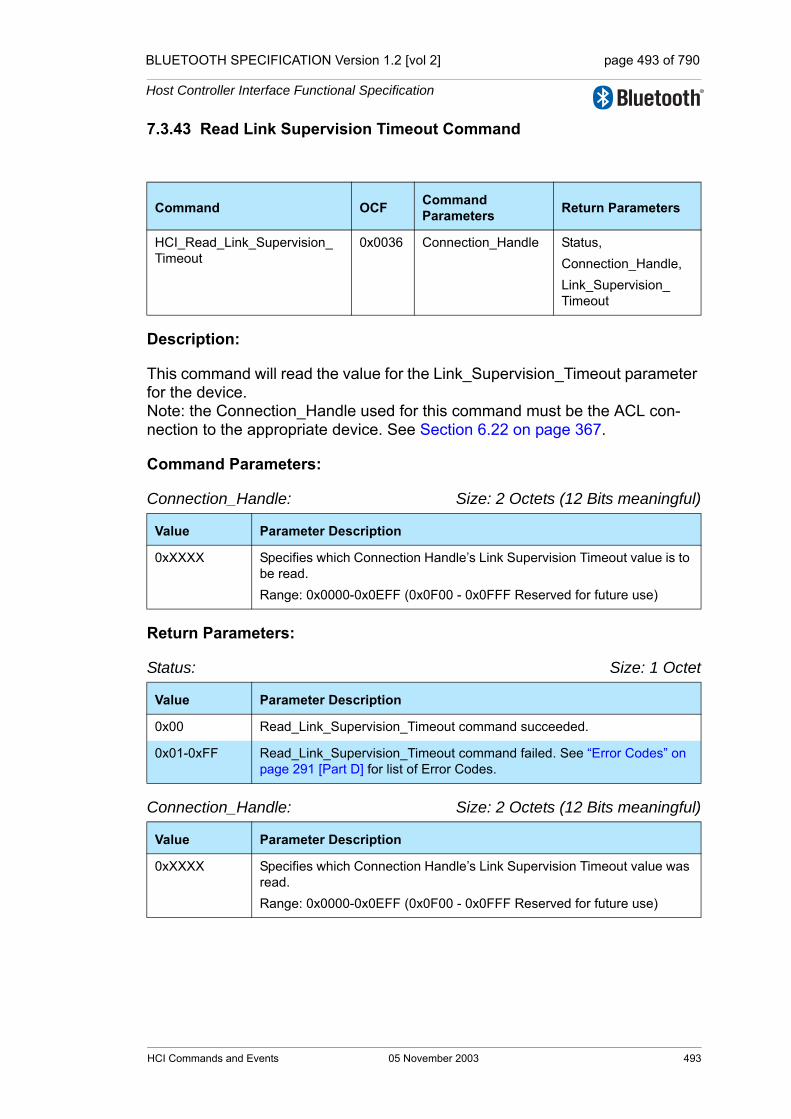
BLUETOOTH SPECIFICATION Version 1.2 [vol 2] page 493 of 790
Host Controller Interface Functional Specification
7.3.43 Read Link Supervision Timeout Command
Description:
This command will read the value for the Link_Supervision_Timeout parameter for the device. Note: the Connection_Handle used for this command must be the ACL con-nection to the appropriate device. See Section 6.22 on page 367.
Command Parameters:
Connection_Handle: Size: 2 Octets (12 Bits meaningful)
Return Parameters:
Status: Size: 1 Octet
Connection_Handle: Size: 2 Octets (12 Bits meaningful)
Command OCF Command Parameters Return Parameters
HCI_Read_Link_Supervision_Timeout
0x0036 Connection_Handle Status, Connection_Handle, Link_Supervision_Timeout
Value Parameter Description
0xXXXX Specifies which Connection Handle’s Link Supervision Timeout value is to be read.Range: 0x0000-0x0EFF (0x0F00 - 0x0FFF Reserved for future use)
Value Parameter Description
0x00 Read_Link_Supervision_Timeout command succeeded.
0x01-0xFF Read_Link_Supervision_Timeout command failed. See “Error Codes” on page 291 [Part D] for list of Error Codes.
Value Parameter Description
0xXXXX Specifies which Connection Handle’s Link Supervision Timeout value was read.Range: 0x0000-0x0EFF (0x0F00 - 0x0FFF Reserved for future use)
HCI Commands and Events 05 November 2003 493

BLUETOOTH SPECIFICATION Version 1.2 [vol 2] page 494 of 790
Host Controller Interface Functional Specification
Link_Supervision_Timeout: Size: 2 Octets
Event(s) generated (unless masked away):
When the Read_Link_Supervision_Timeout command has completed, a Com-mand Complete event will be generated.
7.3.44 Write Link Supervision Timeout Command
Description:
This command will write the value for the Link_Supervision_Timeout parameter for the device. Note: the Connection_Handle used for this command must be the ACL con-nection to the appropriate device. This command will set the Link_Supervision_Timeout values for other Synchronous Connection_Handles to that device. See Section 6.22 on page 367.
Command Parameters:
Connection_Handle: Size: 2 Octets (12 Bits meaningful)
Value Parameter Description
0x0000 No Link_Supervision_Timeout.
N = 0xXXXX Measured in Number of Baseband slotsLink_Supervision_Timeout = N * 0.625 msec (1 Baseband slot)Range for N: 0x0001 – 0xFFFFTime Range: 0.625ms - 40.9 sec
Command OCF Command Parameters Return Parameters
HCI_Write_Link_Supervision_Timeout
0x0037 Connection_Handle,Link_Supervision_Timeout
Status,Connection_Handle
Value Parameter Description
0xXXXX Specifies which Connection Handle’s Link Supervision Timeout value is to be written.Range: 0x0000-0x0EFF (0x0F00 - 0x0FFF Reserved for future use)
494 05 November 2003 HCI Commands and Events
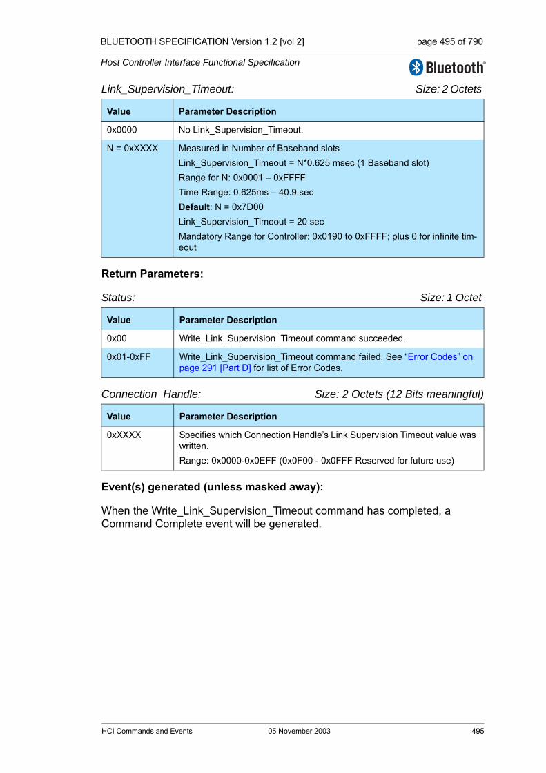
BLUETOOTH SPECIFICATION Version 1.2 [vol 2] page 495 of 790
Host Controller Interface Functional Specification
Link_Supervision_Timeout: Size: 2 Octets
Return Parameters:
Status: Size: 1 Octet
Connection_Handle: Size: 2 Octets (12 Bits meaningful)
Event(s) generated (unless masked away):
When the Write_Link_Supervision_Timeout command has completed, a Command Complete event will be generated.
Value Parameter Description
0x0000 No Link_Supervision_Timeout.
N = 0xXXXX Measured in Number of Baseband slotsLink_Supervision_Timeout = N*0.625 msec (1 Baseband slot)Range for N: 0x0001 – 0xFFFFTime Range: 0.625ms – 40.9 secDefault: N = 0x7D00 Link_Supervision_Timeout = 20 sec Mandatory Range for Controller: 0x0190 to 0xFFFF; plus 0 for infinite tim-eout
Value Parameter Description
0x00 Write_Link_Supervision_Timeout command succeeded.
0x01-0xFF Write_Link_Supervision_Timeout command failed. See “Error Codes” on page 291 [Part D] for list of Error Codes.
Value Parameter Description
0xXXXX Specifies which Connection Handle’s Link Supervision Timeout value was written.Range: 0x0000-0x0EFF (0x0F00 - 0x0FFF Reserved for future use)
HCI Commands and Events 05 November 2003 495
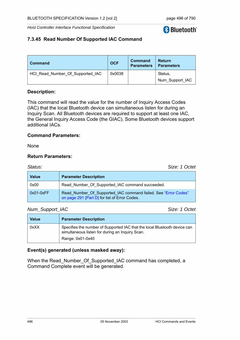
BLUETOOTH SPECIFICATION Version 1.2 [vol 2] page 496 of 790
Host Controller Interface Functional Specification
7.3.45 Read Number Of Supported IAC Command
Description:
This command will read the value for the number of Inquiry Access Codes (IAC) that the local Bluetooth device can simultaneous listen for during an Inquiry Scan. All Bluetooth devices are required to support at least one IAC, the General Inquiry Access Code (the GIAC). Some Bluetooth devices support additional IACs.
Command Parameters:
None
Return Parameters:
Status: Size: 1 Octet
Num_Support_IAC Size: 1 Octet
Event(s) generated (unless masked away):
When the Read_Number_Of_Supported_IAC command has completed, a Command Complete event will be generated.
Command OCF Command Parameters
Return Parameters
HCI_Read_Number_Of_Supported_IAC 0x0038 Status, Num_Support_IAC
Value Parameter Description
0x00 Read_Number_Of_Supported_IAC command succeeded.
0x01-0xFF Read_Number_Of_Supported_IAC command failed. See “Error Codes” on page 291 [Part D] for list of Error Codes.
Value Parameter Description
0xXX Specifies the number of Supported IAC that the local Bluetooth device can simultaneous listen for during an Inquiry Scan.Range: 0x01-0x40
496 05 November 2003 HCI Commands and Events
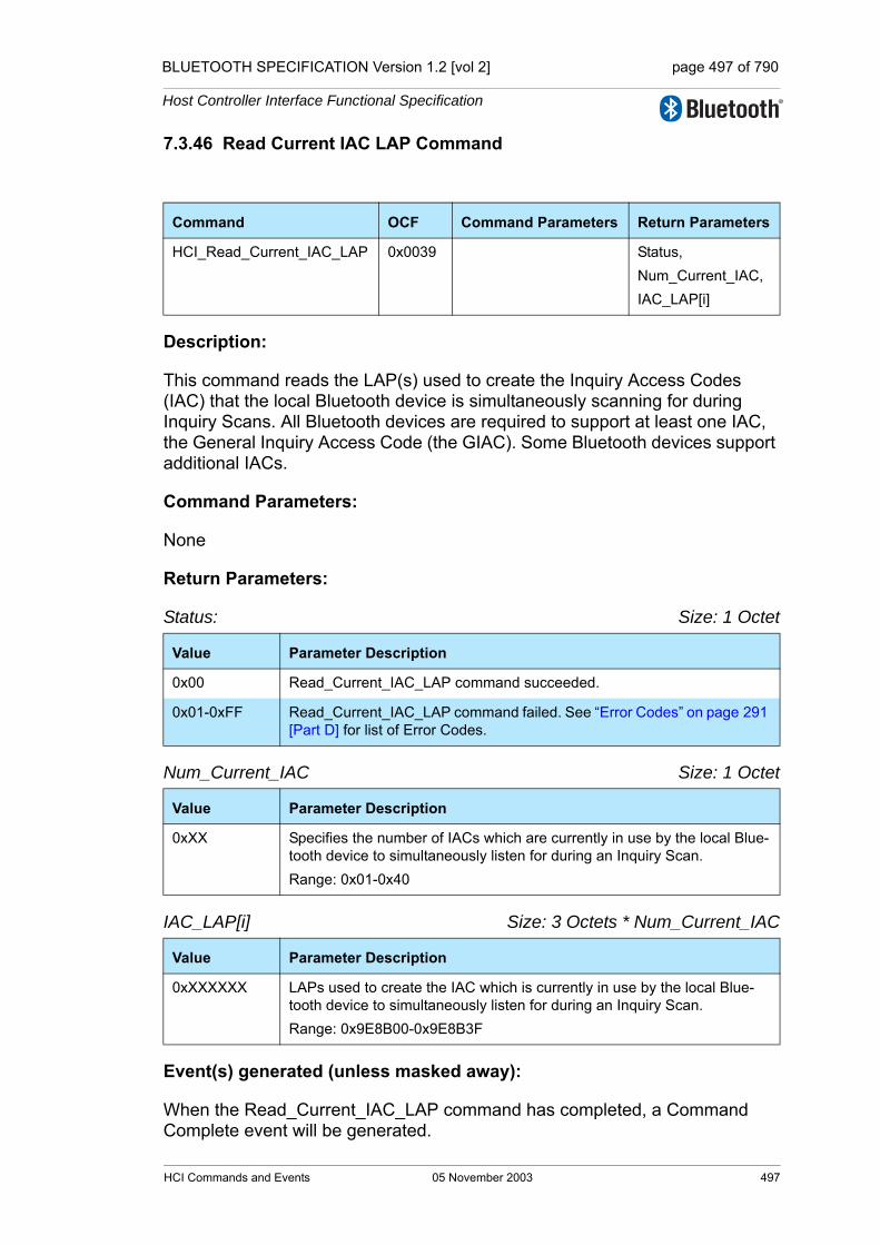
BLUETOOTH SPECIFICATION Version 1.2 [vol 2] page 497 of 790
Host Controller Interface Functional Specification
7.3.46 Read Current IAC LAP Command
Description:
This command reads the LAP(s) used to create the Inquiry Access Codes (IAC) that the local Bluetooth device is simultaneously scanning for during Inquiry Scans. All Bluetooth devices are required to support at least one IAC, the General Inquiry Access Code (the GIAC). Some Bluetooth devices support additional IACs.
Command Parameters:
None
Return Parameters:
Status: Size: 1 Octet
Num_Current_IAC Size: 1 Octet
IAC_LAP[i] Size: 3 Octets * Num_Current_IAC
Event(s) generated (unless masked away):
When the Read_Current_IAC_LAP command has completed, a Command Complete event will be generated.
Command OCF Command Parameters Return Parameters
HCI_Read_Current_IAC_LAP 0x0039 Status, Num_Current_IAC,IAC_LAP[i]
Value Parameter Description
0x00 Read_Current_IAC_LAP command succeeded.
0x01-0xFF Read_Current_IAC_LAP command failed. See “Error Codes” on page 291 [Part D] for list of Error Codes.
Value Parameter Description
0xXX Specifies the number of IACs which are currently in use by the local Blue-tooth device to simultaneously listen for during an Inquiry Scan.Range: 0x01-0x40
Value Parameter Description
0xXXXXXX LAPs used to create the IAC which is currently in use by the local Blue-tooth device to simultaneously listen for during an Inquiry Scan.Range: 0x9E8B00-0x9E8B3F
HCI Commands and Events 05 November 2003 497

BLUETOOTH SPECIFICATION Version 1.2 [vol 2] page 498 of 790
Host Controller Interface Functional Specification
7.3.47 Write Current IAC LAP Command
Description:
This command writes the LAP(s) used to create the Inquiry Access Codes (IAC) that the local Bluetooth device is simultaneously scanning for during Inquiry Scans. All Bluetooth devices are required to support at least one IAC, the General Inquiry Access Code (the GIAC). Some Bluetooth devices support additional IACs.
This command shall clear any existing IACs and stores Num_Current_IAC and the IAC_LAPs in to the controller. If Num_Current_IAC is greater than Num_Support_IAC then only the first Num_Support_IACs shall be stored in the controller, and a Command Complete event with error code Success (0x00) shall be generated.
Command Parameters:
Num_Current_IAC Size: 1 Octet
IAC_LAP[i] Size: 3 Octets * Num_Current_IAC
Command OCF Command Parameters Return Parameters
HCI_Write_Current_IAC_LAP 0x003A Num_Current_IAC,IAC_LAP[i]
Status
Value Parameter Description
0xXX Specifies the number of IACs which are currently in use by the local Blue-tooth device to simultaneously listen for during an Inquiry Scan.Range: 0x01-0x40
Value Parameter Description
0xXXXXXX LAP(s) used to create IAC which is currently in use by the local Bluetooth device to simultaneously listen for during an Inquiry Scan.Range: 0x9E8B00-0x9E8B3F.The GIAC is the default IAC to be used. If additional IACs are supported, additional default IAC will be determined by the manufacturer.
498 05 November 2003 HCI Commands and Events
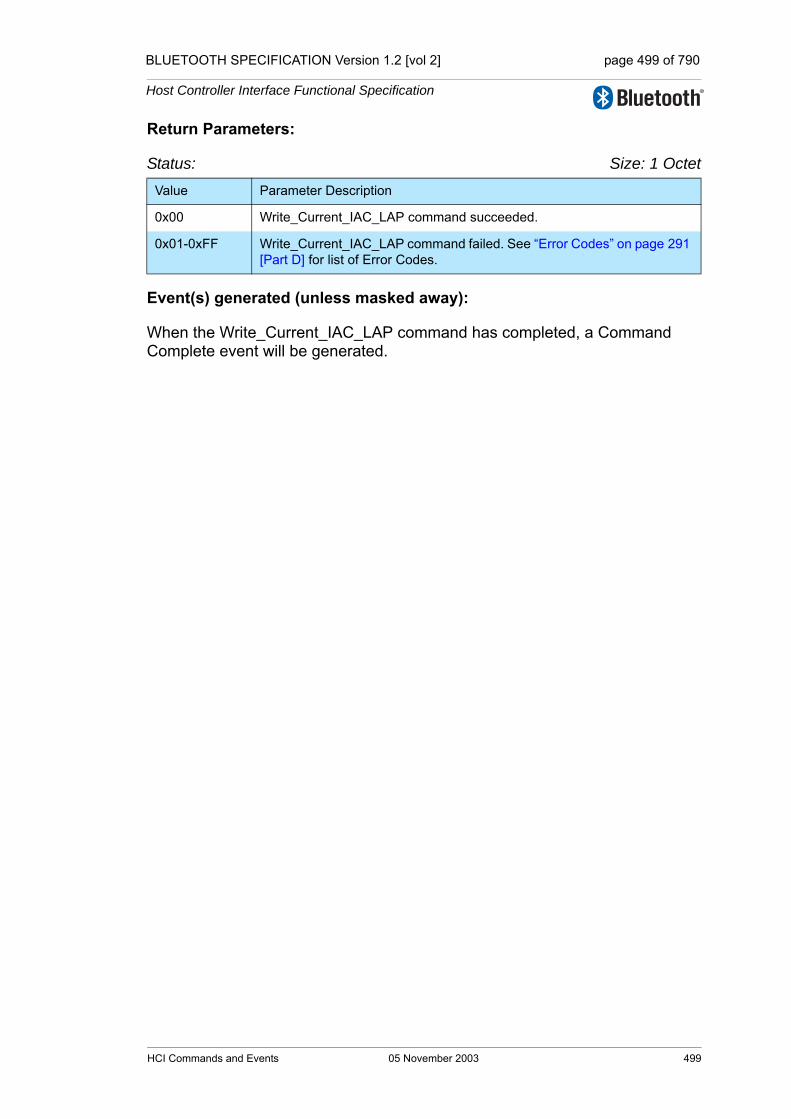
BLUETOOTH SPECIFICATION Version 1.2 [vol 2] page 499 of 790
Host Controller Interface Functional Specification
Return Parameters:
Status: Size: 1 Octet
Event(s) generated (unless masked away):
When the Write_Current_IAC_LAP command has completed, a Command Complete event will be generated.
Value Parameter Description
0x00 Write_Current_IAC_LAP command succeeded.
0x01-0xFF Write_Current_IAC_LAP command failed. See “Error Codes” on page 291 [Part D] for list of Error Codes.
HCI Commands and Events 05 November 2003 499
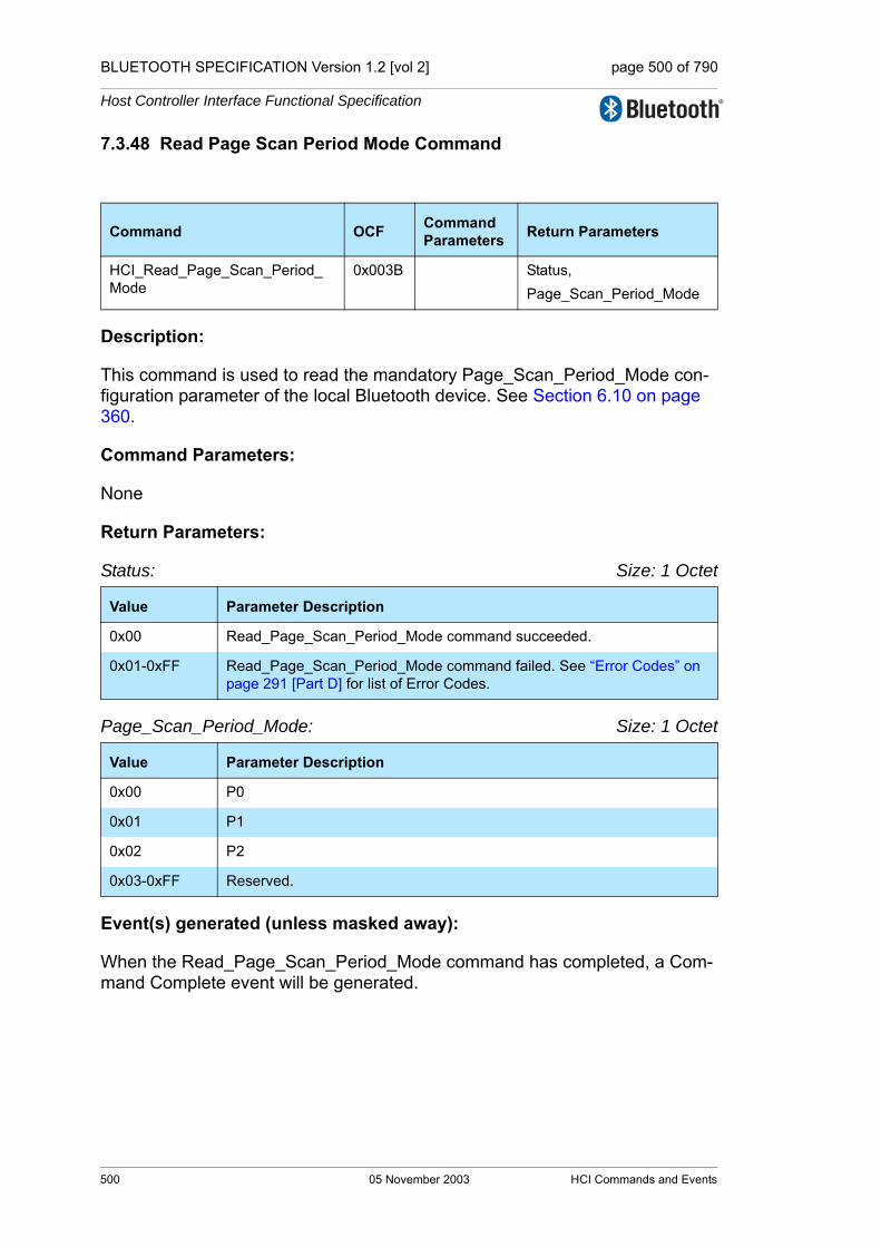
BLUETOOTH SPECIFICATION Version 1.2 [vol 2] page 500 of 790
Host Controller Interface Functional Specification
7.3.48 Read Page Scan Period Mode Command
Description:
This command is used to read the mandatory Page_Scan_Period_Mode con-figuration parameter of the local Bluetooth device. See Section 6.10 on page 360.
Command Parameters:
None
Return Parameters:
Status: Size: 1 Octet
Page_Scan_Period_Mode: Size: 1 Octet
Event(s) generated (unless masked away):
When the Read_Page_Scan_Period_Mode command has completed, a Com-mand Complete event will be generated.
Command OCF Command Parameters Return Parameters
HCI_Read_Page_Scan_Period_Mode
0x003B Status,Page_Scan_Period_Mode
Value Parameter Description
0x00 Read_Page_Scan_Period_Mode command succeeded.
0x01-0xFF Read_Page_Scan_Period_Mode command failed. See “Error Codes” on page 291 [Part D] for list of Error Codes.
Value Parameter Description
0x00 P0
0x01 P1
0x02 P2
0x03-0xFF Reserved.
500 05 November 2003 HCI Commands and Events
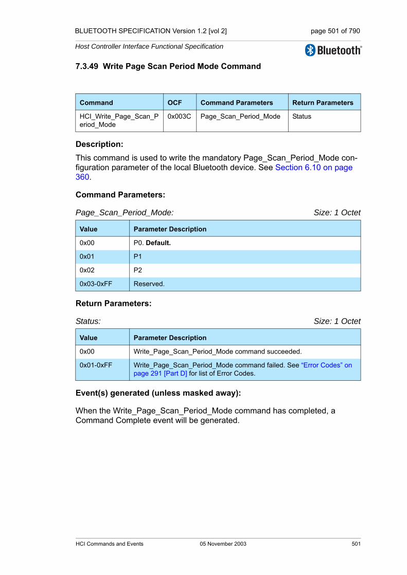
BLUETOOTH SPECIFICATION Version 1.2 [vol 2] page 501 of 790
Host Controller Interface Functional Specification
7.3.49 Write Page Scan Period Mode Command
Description: This command is used to write the mandatory Page_Scan_Period_Mode con-figuration parameter of the local Bluetooth device. See Section 6.10 on page 360.
Command Parameters:
Page_Scan_Period_Mode: Size: 1 Octet
Return Parameters:
Status: Size: 1 Octet
Event(s) generated (unless masked away):
When the Write_Page_Scan_Period_Mode command has completed, a Command Complete event will be generated.
Command OCF Command Parameters Return Parameters
HCI_Write_Page_Scan_Period_Mode
0x003C Page_Scan_Period_Mode Status
Value Parameter Description
0x00 P0. Default.
0x01 P1
0x02 P2
0x03-0xFF Reserved.
Value Parameter Description
0x00 Write_Page_Scan_Period_Mode command succeeded.
0x01-0xFF Write_Page_Scan_Period_Mode command failed. See “Error Codes” on page 291 [Part D] for list of Error Codes.
HCI Commands and Events 05 November 2003 501

BLUETOOTH SPECIFICATION Version 1.2 [vol 2] page 502 of 790
Host Controller Interface Functional Specification
7.3.50 Set AFH Host Channel Classification Command
Description:
The Set_AFH_Host_Channel_Classification command allows the Bluetooth host to specify a channel classification based on its “local information”. This classifica-tion persists until overwritten with a subsequent HCI Set_AFH_Host_Channel_Classification command or until the Controller is reset.
This command shall be supported by a device that declares support for any of the AFH_capable_master, AFH_classification_slave or AFH_classification_master features.
If this command is used, then updates should be sent within 10 seconds, of the host knowing that the channel classification has changed. The interval between two successive commands sent shall be at least 1 second.
Command Parameters:
AFH_Host_Channel_Classification: Size: 10 Octets (79 Bits meaningful)
Return Parameters:
Status: Size: 1 Octet
Event(s) generated (unless masked away):
When the Set_AFH_Host_Channel_Classification command has completed, a Command Complete event will be generated.
Command OCF Command Parameters Return Parameters
Set_AFH_Host_Channel_Classification
0x003F AFH_Host_Channel_Classification
Status
Value Parameter Description
0xXXXXXXXXXXXXXXXXXXXX
This parameter contains 79 1-bit field.
The nth such field (in the range 0 to 78) contains the value for channel n:Channel n is bad = 0Channel n is unknown = 1The most significant bit is reserved and shall be set to 0At least Nmin channels shall be marked as unknown. (See Baseband Specification, Section 2.3.1, on page 63)
Value Parameter Description
0x00 Set_AFH_Host_Channel_Classification command succeeded.
0x01-0xFF Set_AFH_Host_Channel_Classification command failed. “Error Codes” on page 291 [Part D] for list of Error Codes.
502 05 November 2003 HCI Commands and Events

BLUETOOTH SPECIFICATION Version 1.2 [vol 2] page 503 of 790
Host Controller Interface Functional Specification
7.3.51 Read Inquiry Scan Type Command
Description:
This command is used to read the Inquiry_Scan_Type configuration parameter of the local Bluetooth device. See Section 6.4 on page 358. For details, see the Baseband Specification, “Inquiry scan substate” on page 144 [Part B].
Command Parameters:
None
Return Parameters:
Status: Size: 1 Octet
Inquiry_Scan_Type: Size: 1 Octet
Event(s) generated (unless masked away):
When the Read_Inquiry_Scan_Type command has completed, a Command Complete event will be generated.
Command OCF Command Parameters
Return Parameters
HCI_Read_Inquiry_Scan_Type 0x0042 Status, Inquiry_Scan_Type
Value Parameter Description
0x00 Read_Inquiry_Scan_Type command succeeded
0x01-0xFF Read_Inquiry_Scan_Type command failed. See “Error Codes” on page 291 [Part D] for list of Error Codes.
Value Parameter Description
0x00 Mandatory: Standard Scan (default)
0x01 Optional: Interlaced Scan
0x02-0xFF Reserved
HCI Commands and Events 05 November 2003 503

BLUETOOTH SPECIFICATION Version 1.2 [vol 2] page 504 of 790
Host Controller Interface Functional Specification
7.3.52 Write Inquiry Scan Type Command
Description:
This command is used to write the Inquiry Scan Type configuration parameter of the local Bluetooth device. See Section 6.4 on page 358. For details, see the Baseband Specification, “Inquiry scan substate” on page 144 [Part B].
Command Parameters:
Scan_Type: Size: 1 Octet
Return Parameters:
Status: Size: 1 Octet
Event(s) generated (unless masked away):
When the Write_Inquiry_Scan_Type command has completed, a Command Complete event will be generated.
Command OCF Command Parameters Return Parameters
HCI_Write_Inquiry_Scan_Type 0x0043 Scan_Type Status
Value Parameter Description
0x00 Mandatory: Standard Scan (default)
0x01 Optional: Interlaced Scan
0x02-0xFF Reserved
Value Parameter Description
0x00 Write_Inquiry_Scan_Type command succeeded
0x01-0xFF Write_Inquiry_Scan_Type command failed. See “Error Codes” on page 291 [Part D] for list of Error Codes.
504 05 November 2003 HCI Commands and Events
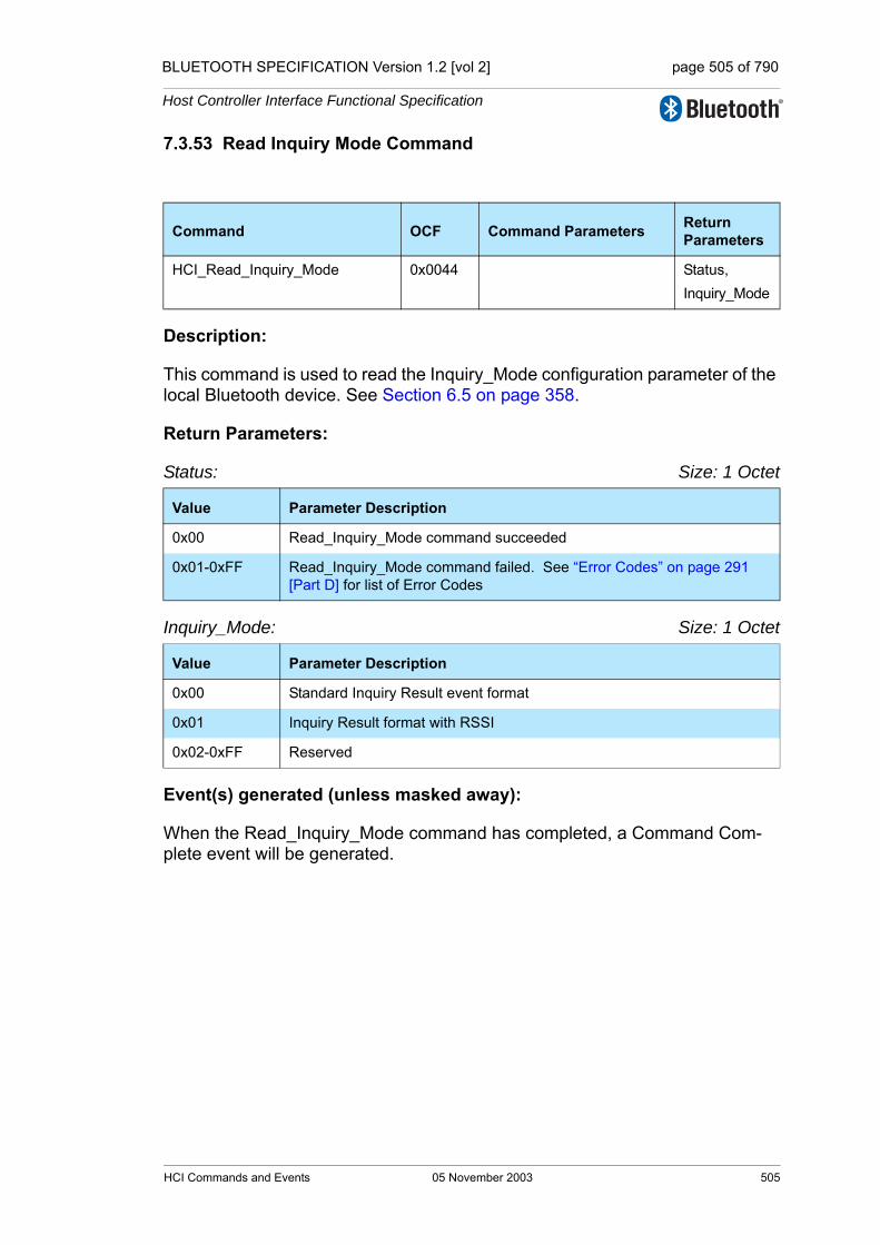
BLUETOOTH SPECIFICATION Version 1.2 [vol 2] page 505 of 790
Host Controller Interface Functional Specification
7.3.53 Read Inquiry Mode Command
Description:
This command is used to read the Inquiry_Mode configuration parameter of the local Bluetooth device. See Section 6.5 on page 358.
Return Parameters:
Status: Size: 1 Octet
Inquiry_Mode: Size: 1 Octet
Event(s) generated (unless masked away):
When the Read_Inquiry_Mode command has completed, a Command Com-plete event will be generated.
Command OCF Command Parameters Return Parameters
HCI_Read_Inquiry_Mode 0x0044 Status, Inquiry_Mode
Value Parameter Description
0x00 Read_Inquiry_Mode command succeeded
0x01-0xFF Read_Inquiry_Mode command failed. See “Error Codes” on page 291 [Part D] for list of Error Codes
Value Parameter Description
0x00 Standard Inquiry Result event format
0x01 Inquiry Result format with RSSI
0x02-0xFF Reserved
HCI Commands and Events 05 November 2003 505
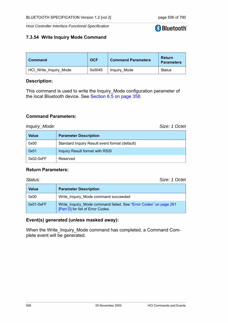
BLUETOOTH SPECIFICATION Version 1.2 [vol 2] page 506 of 790
Host Controller Interface Functional Specification
7.3.54 Write Inquiry Mode Command
Description:
This command is used to write the Inquiry_Mode configuration parameter of the local Bluetooth device. See Section 6.5 on page 358.
Command Parameters:
Inquiry_Mode: Size: 1 Octet
Return Parameters:
Status: Size: 1 Octet
Event(s) generated (unless masked away):
When the Write_Inquiry_Mode command has completed, a Command Com-plete event will be generated.
Command OCF Command Parameters Return Parameters
HCI_Write_Inquiry_Mode 0x0045 Inquiry_Mode Status
Value Parameter Description
0x00 Standard Inquiry Result event format (default)
0x01 Inquiry Result format with RSSI
0x02-0xFF Reserved
Value Parameter Description
0x00 Write_Inquiry_Mode command succeeded
0x01-0xFF Write_Inquiry_Mode command failed. See “Error Codes” on page 291 [Part D] for list of Error Codes.
506 05 November 2003 HCI Commands and Events
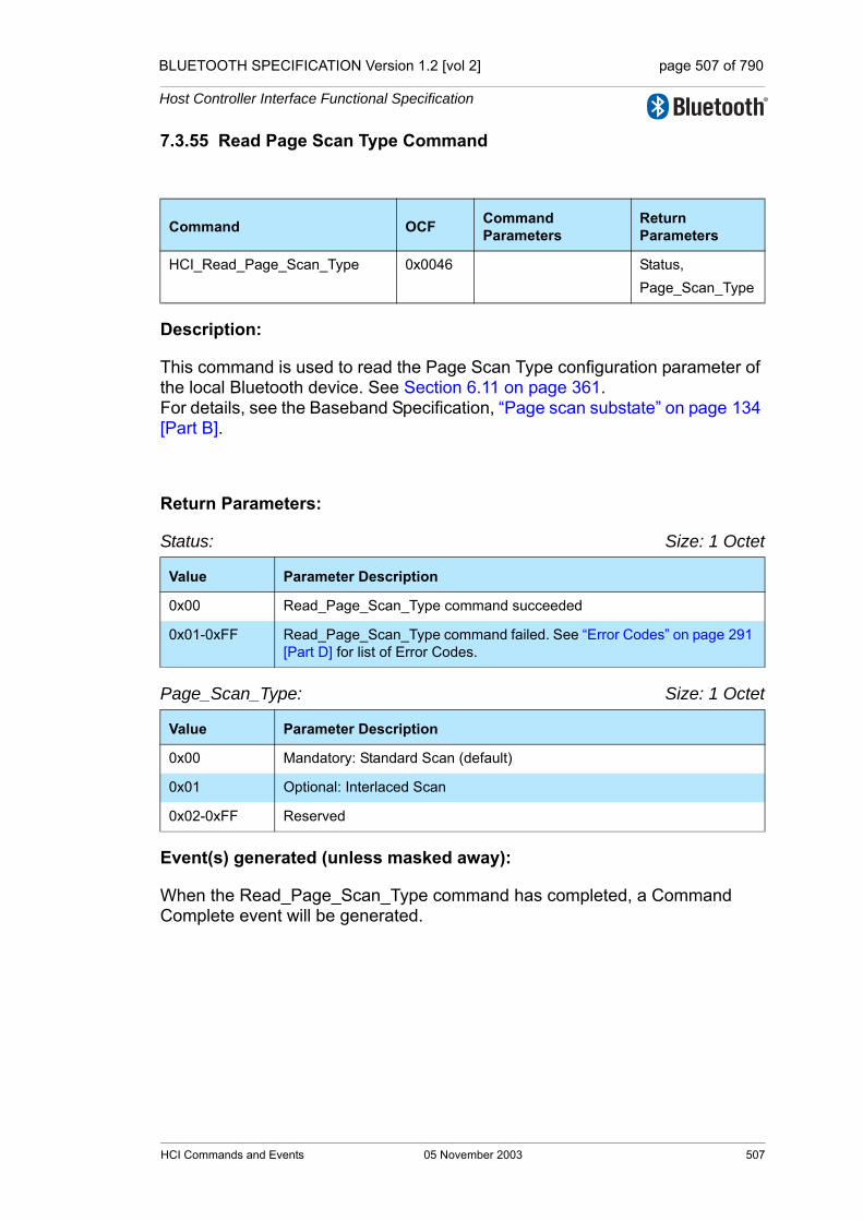
BLUETOOTH SPECIFICATION Version 1.2 [vol 2] page 507 of 790
Host Controller Interface Functional Specification
7.3.55 Read Page Scan Type Command
Description:
This command is used to read the Page Scan Type configuration parameter of the local Bluetooth device. See Section 6.11 on page 361. For details, see the Baseband Specification, “Page scan substate” on page 134 [Part B].
Return Parameters:
Status: Size: 1 Octet
Page_Scan_Type: Size: 1 Octet
Event(s) generated (unless masked away):
When the Read_Page_Scan_Type command has completed, a Command Complete event will be generated.
Command OCF Command Parameters
Return Parameters
HCI_Read_Page_Scan_Type 0x0046 Status,Page_Scan_Type
Value Parameter Description
0x00 Read_Page_Scan_Type command succeeded
0x01-0xFF Read_Page_Scan_Type command failed. See “Error Codes” on page 291 [Part D] for list of Error Codes.
Value Parameter Description
0x00 Mandatory: Standard Scan (default)
0x01 Optional: Interlaced Scan
0x02-0xFF Reserved
HCI Commands and Events 05 November 2003 507
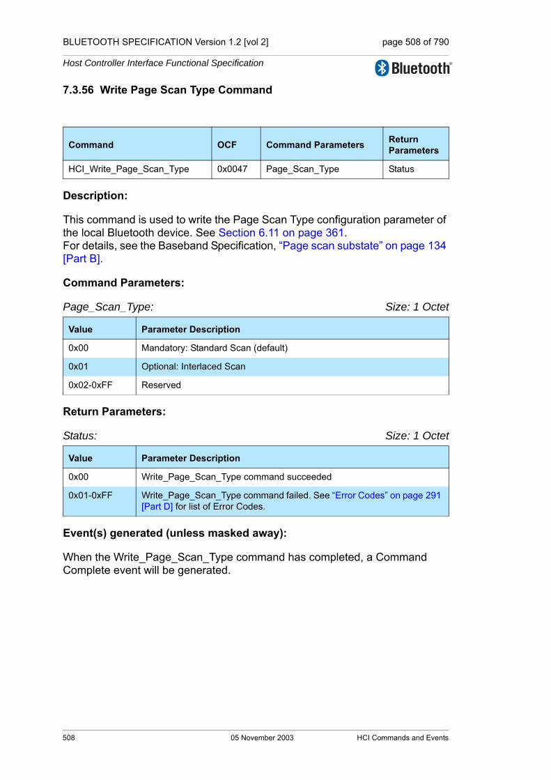
BLUETOOTH SPECIFICATION Version 1.2 [vol 2] page 508 of 790
Host Controller Interface Functional Specification
7.3.56 Write Page Scan Type Command
Description:
This command is used to write the Page Scan Type configuration parameter of the local Bluetooth device. See Section 6.11 on page 361.For details, see the Baseband Specification, “Page scan substate” on page 134 [Part B].
Command Parameters:
Page_Scan_Type: Size: 1 Octet
Return Parameters:
Status: Size: 1 Octet
Event(s) generated (unless masked away):
When the Write_Page_Scan_Type command has completed, a Command Complete event will be generated.
Command OCF Command Parameters Return Parameters
HCI_Write_Page_Scan_Type 0x0047 Page_Scan_Type Status
Value Parameter Description
0x00 Mandatory: Standard Scan (default)
0x01 Optional: Interlaced Scan
0x02-0xFF Reserved
Value Parameter Description
0x00 Write_Page_Scan_Type command succeeded
0x01-0xFF Write_Page_Scan_Type command failed. See “Error Codes” on page 291 [Part D] for list of Error Codes.
508 05 November 2003 HCI Commands and Events

BLUETOOTH SPECIFICATION Version 1.2 [vol 2] page 509 of 790
Host Controller Interface Functional Specification
7.3.57 Read AFH Channel Assessment Mode Command
Description:
The Read_AFH_Channel_Assessment_Mode command reads the value for the AFH_Channel_Assessment_Mode parameter. The AFH_Channel_Assessment_Mode parameter controls whether the controller’s channel assessment scheme is enabled or disabled.
This command shall be supported by a device that declares support for any of the AFH_capable_master, AFH_classification_slave or AFH_classification_master features.
Return Parameters:
Status: Size: 1 Octet
AFH_Channel_Assessment_Mode:: Size: 1 Octet
Event(s) generated (unless masked away):
When the Read_AFH_Channel_Assessment_Mode command has completed, a Command Complete event will be generated.
Command OCF Command Parameters
Return Parameters
Read_AFH_Channel_Assessment_Mode
0x0048 Status, AFH_Channel_Assessment_Mode
Value Parameter Description
0x00 Read_AFH_Channel_Assessment_Mode command succeeded.
0x01-0xFF Read_AFH_Channel_Assessment_Mode command failed. See “Error Codes” on page 291 [Part D] for list of Error Codes.
Value Parameter Description
0x00 Controller channel assessment disabled.
0x01 Controller channel assessment enabled.
0x02-0xFF Reserved for future use.
HCI Commands and Events 05 November 2003 509

BLUETOOTH SPECIFICATION Version 1.2 [vol 2] page 510 of 790
Host Controller Interface Functional Specification
7.3.58 Write AFH Channel Assessment Mode Command
Description:
The Write_AFH_Channel_Assessment_Mode command writes the value for the AFH_Channel_Assessment_Mode parameter. The AFH_Channel_Assessment_Mode parameter controls whether the Controller’s channel assessment scheme is enabled or disabled.
Disabling channel assessment forces all channels to be unknown in the local classification, but does not affect the AFH_reporting_mode or support for the Set_AFH_Host_Channel_Classification command. A slave in the AFH_reporting_enabled state shall continue to send LMP channel classifica-tion messages for any changes to the channel classification caused by either this command (altering the AFH_Channel_Assessment_Mode) or HCI Set_AFH_Host_Channel_Classification command (providing a new channel classification from the Host).
This command shall be supported by a device that declares support for any of the AFH_capable_master, AFH_classification_slave or AFH_classification_master features.
If the AFH_Channel_Assessment_Mode parameter is enabled and the Control-ler does not support a channel assessment scheme, other than via the Set_AFH_Host_Channel_Classification command, then a Status parameter of ‘Channel Assessment Not Supported’ should be returned. See “Error Codes” on page 291 [Part D] for list of Error Codes.
If the Controller supports a channel assessment scheme then the default AFH_Channel_Assessment_Mode is enabled, otherwise the default is dis-abled.
Command Parameters:
AFH_Channel_Assessment_Mode: Size: 1 Octet
Command OCF Command Parameters Return Parameters
Write_AFH_Channel_Assessment_Mode
0x0049 AFH_Channel_Assessment_Mode
Status
Value Parameter Description
0x00 Controller channel assessment disabled.
0x01 Controller channel assessment enabled.
0x02-0xFF Reserved for future use.
510 05 November 2003 HCI Commands and Events
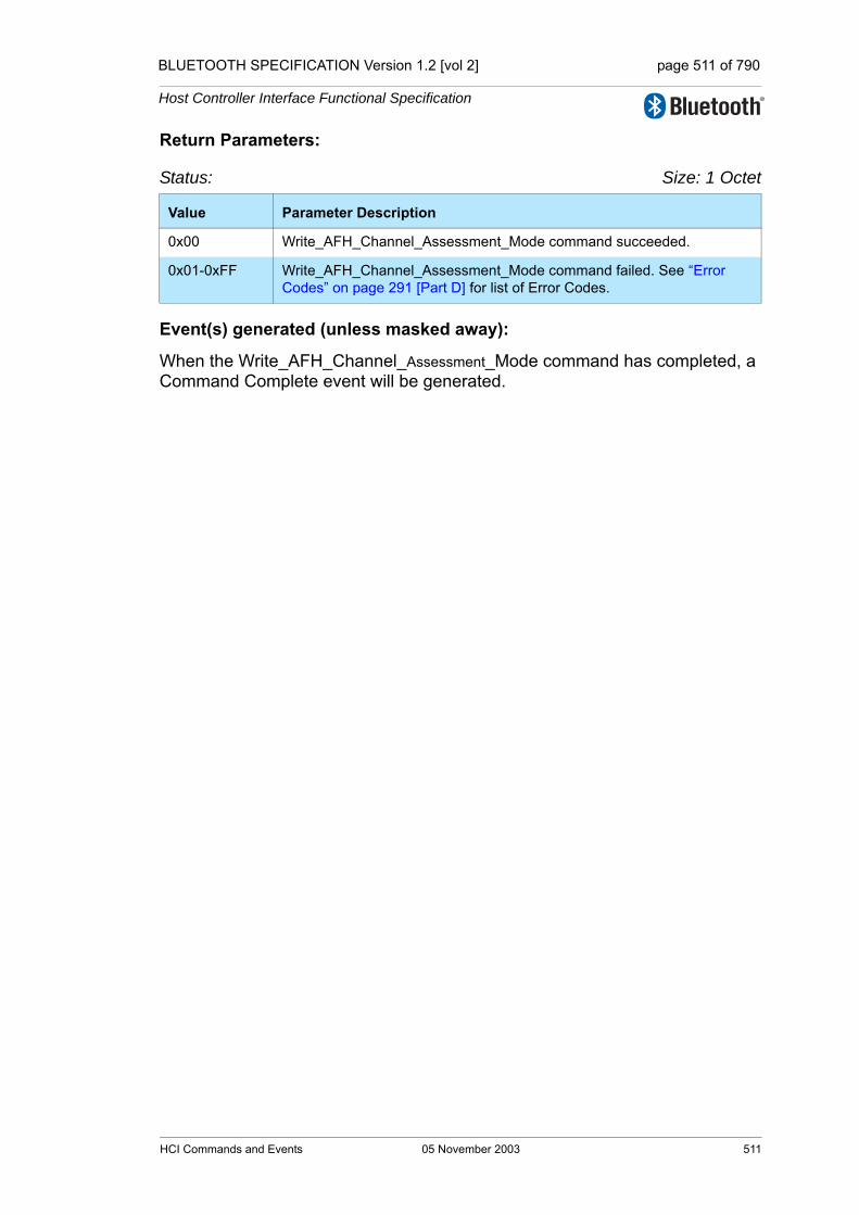
BLUETOOTH SPECIFICATION Version 1.2 [vol 2] page 511 of 790
Host Controller Interface Functional Specification
Return Parameters:
Status: Size: 1 Octet
Event(s) generated (unless masked away):
When the Write_AFH_Channel_Assessment_Mode command has completed, a Command Complete event will be generated.
Value Parameter Description
0x00 Write_AFH_Channel_Assessment_Mode command succeeded.
0x01-0xFF Write_AFH_Channel_Assessment_Mode command failed. See “Error Codes” on page 291 [Part D] for list of Error Codes.
HCI Commands and Events 05 November 2003 511
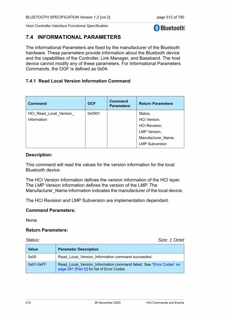
BLUETOOTH SPECIFICATION Version 1.2 [vol 2] page 512 of 790
Host Controller Interface Functional Specification
7.4 INFORMATIONAL PARAMETERS
The Informational Parameters are fixed by the manufacturer of the Bluetooth hardware. These parameters provide information about the Bluetooth device and the capabilities of the Controller, Link Manager, and Baseband. The host device cannot modify any of these parameters. For Informational Parameters Commands, the OGF is defined as 0x04.
7.4.1 Read Local Version Information Command
Description:
This command will read the values for the version information for the local Bluetooth device.
The HCI Version information defines the version information of the HCI layer. The LMP Version information defines the version of the LMP. The Manufacturer_Name information indicates the manufacturer of the local device.
The HCI Revision and LMP Subversion are implementation dependant.
Command Parameters:
None.
Return Parameters:
Status: Size: 1 Octet
Command OCF Command Parameters Return Parameters
HCI_Read_Local_Version_Information
0x0001 Status,HCI Version,HCI Revision,LMP Version,Manufacturer_Name,LMP Subversion
Value Parameter Description
0x00 Read_Local_Version_Information command succeeded.
0x01-0xFF Read_Local_Version_Information command failed. See “Error Codes” on page 291 [Part D] for list of Error Codes.
512 05 November 2003 HCI Commands and Events
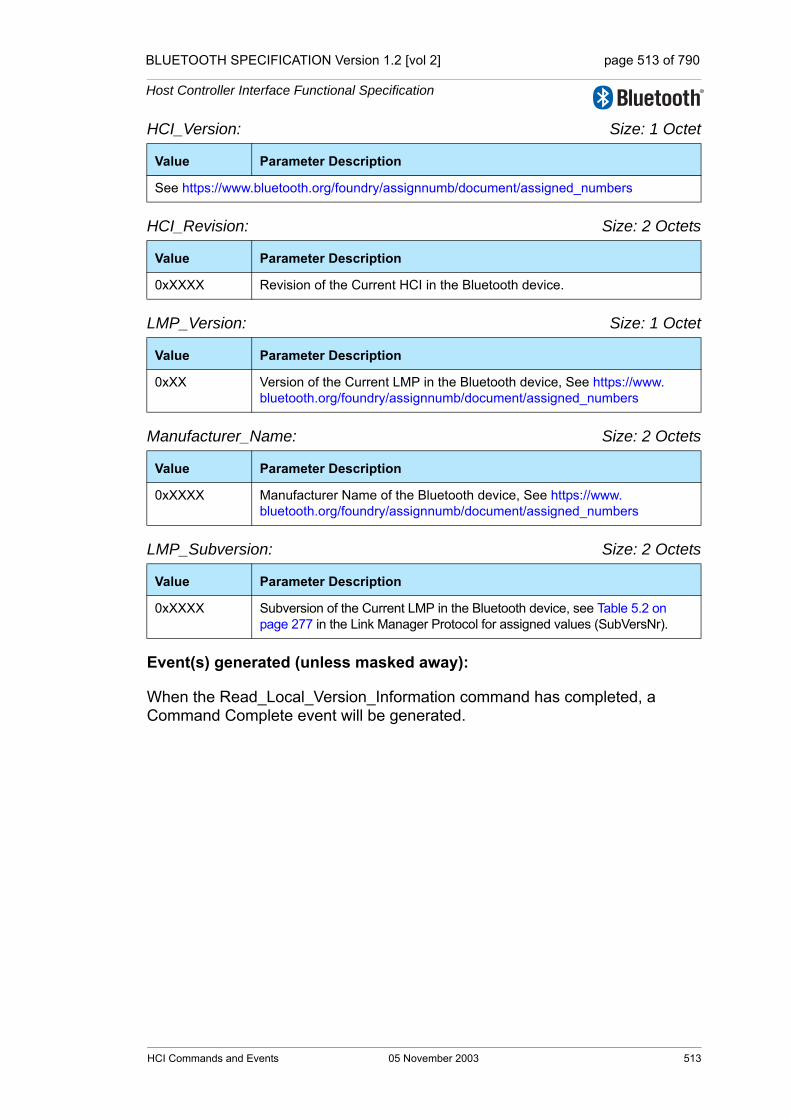
BLUETOOTH SPECIFICATION Version 1.2 [vol 2] page 513 of 790
Host Controller Interface Functional Specification
HCI_Version: Size: 1 Octet
HCI_Revision: Size: 2 Octets
LMP_Version: Size: 1 Octet
Manufacturer_Name: Size: 2 Octets
LMP_Subversion: Size: 2 Octets
Event(s) generated (unless masked away):
When the Read_Local_Version_Information command has completed, a Command Complete event will be generated.
Value Parameter Description
See https://www.bluetooth.org/foundry/assignnumb/document/assigned_numbers
Value Parameter Description
0xXXXX Revision of the Current HCI in the Bluetooth device.
Value Parameter Description
0xXX Version of the Current LMP in the Bluetooth device, See https://www.bluetooth.org/foundry/assignnumb/document/assigned_numbers
Value Parameter Description
0xXXXX Manufacturer Name of the Bluetooth device, See https://www.bluetooth.org/foundry/assignnumb/document/assigned_numbers
Value Parameter Description
0xXXXX Subversion of the Current LMP in the Bluetooth device, see Table 5.2 on page 277 in the Link Manager Protocol for assigned values (SubVersNr).
HCI Commands and Events 05 November 2003 513

BLUETOOTH SPECIFICATION Version 1.2 [vol 2] page 514 of 790
Host Controller Interface Functional Specification
7.4.2 Read Local Supported Commands Command
Description:
This command reads the list of HCI commands supported for the local device.
This command will return the Supported Commands configuration parameter. It is implied that if a command is listed as supported, the feature underlying that command is also supported.
See Section 6.26 on page 369 for more information.
Command Parameters:
None.
Return Parameters:
Status: Size: 1 Octet
Supported Commands: Size: 64 Octets
Event(s) generated (unless masked away):
When the Read Local Supported Commands command has completed a Com-mand Complete event will be generated.
Command OCF Command Parameters Return Parameters
HCI_ Read_Local_Supported_Commands 0x0002 Status,
Supported Commands
Value Parameter Description
0 Read Local Supported Commands command succeeded
0x01-0xff Read Local Supported Commands command failed. See “Error Codes” on page 291 [Part D] for list of Error Codes.
Value Parameter Description
Bit mask for each HCI Command. If a bit is 1, the radio supports the corre-sponding command and the features required for the command. Unsup-ported or undefined commands shall be set to 0.See Section 6.26, “Supported Commands,” on page 369.
514 05 November 2003 HCI Commands and Events
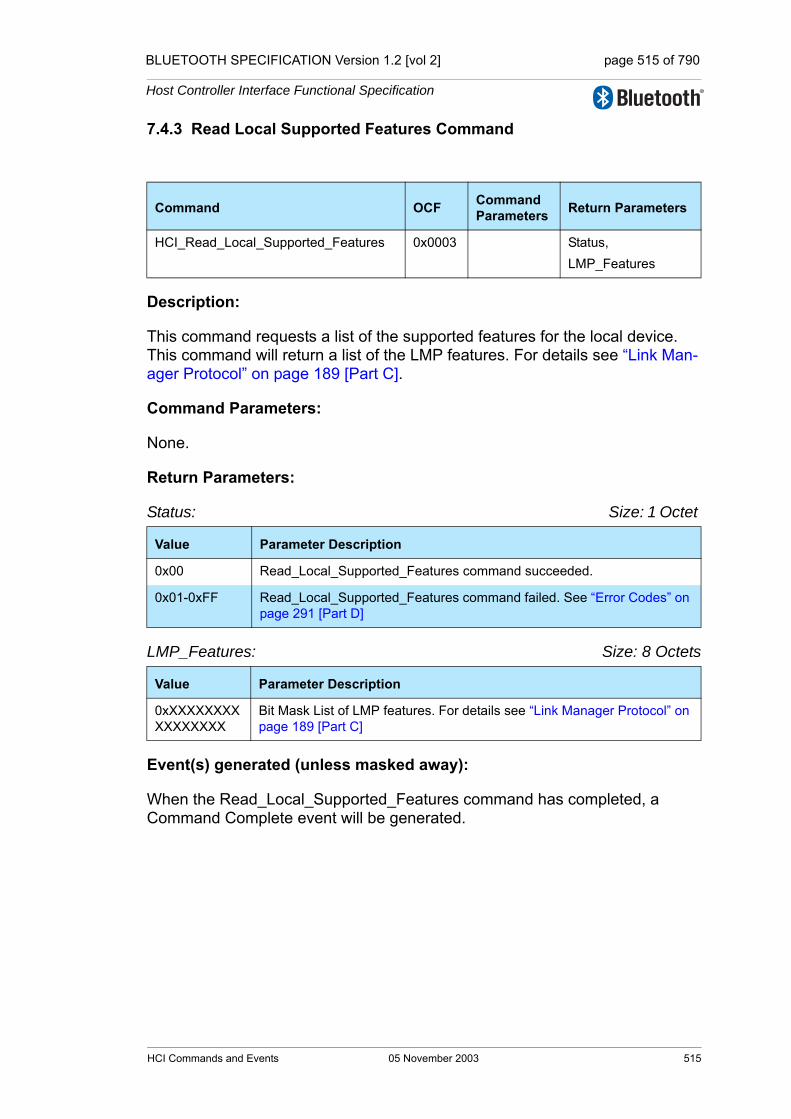
BLUETOOTH SPECIFICATION Version 1.2 [vol 2] page 515 of 790
Host Controller Interface Functional Specification
7.4.3 Read Local Supported Features Command
Description:
This command requests a list of the supported features for the local device. This command will return a list of the LMP features. For details see “Link Man-ager Protocol” on page 189 [Part C].
Command Parameters:
None.
Return Parameters:
Status: Size: 1 Octet
LMP_Features: Size: 8 Octets
Event(s) generated (unless masked away):
When the Read_Local_Supported_Features command has completed, a Command Complete event will be generated.
Command OCF Command Parameters Return Parameters
HCI_Read_Local_Supported_Features 0x0003 Status,LMP_Features
Value Parameter Description
0x00 Read_Local_Supported_Features command succeeded.
0x01-0xFF Read_Local_Supported_Features command failed. See “Error Codes” on page 291 [Part D]
Value Parameter Description
0xXXXXXXXXXXXXXXXX
Bit Mask List of LMP features. For details see “Link Manager Protocol” on page 189 [Part C]
HCI Commands and Events 05 November 2003 515

BLUETOOTH SPECIFICATION Version 1.2 [vol 2] page 516 of 790
Host Controller Interface Functional Specification
7.4.4 Read Local Extended Features Command
Description:
The HCI_Read_Local_Extended_Features command returns the requested page of the extended LMP features.
Command Parameters:
Page Number: Size: 1 Octet
Return Parameters:
Status: Size: 1 Octet
Page Number: Size: 1 Octet
Maximum Page Number: Size: 1 Octet
Command OCF Command Parameters Return Parameters
HCI_Read_Local_Extended_Features
0x0004 Page number Status, Page number, Maximum Page Number, Extended_LMP_Features
Value Parameter Description
0x00 Requests the normal LMP features as returned by HCI_Read_Local_Supported_Features
0x01-0xFF Return the corresponding page of features
Value Parameter Description
0x00 HCI_Read_Local_Extended_Features command succeeded
0x01-0xFF HCI_Read_Local_Extended_Features command failed. See “Error Codes” on page 291 [Part D] for list of error codes
Value Parameter Description
0x00 The normal LMP features as returned by HCI_Read_Local_Supported_Features
0x01-0xFF The page number of the features returned
Value Parameter Description
0x00-0xFF The highest features page number which contains non-zero bits for the local device
516 05 November 2003 HCI Commands and Events

BLUETOOTH SPECIFICATION Version 1.2 [vol 2] page 517 of 790
Host Controller Interface Functional Specification
Extended_LMP_Features: Size: 8 Octets
Event(s) generated (unless masked away):
When the Controller receives the HCI_Read_Local_Extended_Features com-mand the Controller sends the Command Complete command to the Host con-taining the requested information.
Value Parameter Description
0xFFFFFFFFFFFFFFFF Bit map of requested page of LMP features. See LMP specification for details
HCI Commands and Events 05 November 2003 517

BLUETOOTH SPECIFICATION Version 1.2 [vol 2] page 518 of 790
Host Controller Interface Functional Specification
7.4.5 Read Buffer Size Command
Description:
The Read_Buffer_Size command is used to read the maximum size of the data portion of HCI ACL and synchronous Data Packets sent from the Host to the Controller. The Host will segment the data to be transmitted from the Host to the Controller according to these sizes, so that the HCI Data Packets will con-tain data with up to these sizes. The Read_Buffer_Size command also returns the total number of HCI ACL and synchronous Data Packets that can be stored in the data buffers of the Controller. The Read_Buffer_Size command must be issued by the Host before it sends any data to the Controller.
The HC_ACL_Data_Packet_Length return parameter will be used to determine the size of the L2CAP segments contained in ACL Data Packets, which are transferred from the Host to the Controller to be broken up into baseband pack-ets by the Link Manager. The HC_Synchronous_Data_Packet_Length return parameter is used to determine the maximum size of HCI synchronous Data Packets. Both the Host and the Controller must support command and event packets, where the data portion (excluding header) contained in the packets is 255 octets in size. The HC_Total_Num_ACL_Data_Packets return parameter contains the total number of HCI ACL Data Packets that can be stored in the data buffers of the Controller. The Host will determine how the buffers are to be divided between different Connection Handles. The HC_Total_Num_Synchronous_Data_Packets return parameter gives the same information but for HCI synchronous Data Packets. Note: the HC_ACL_Data_Packet_Length and HC_Synchronous_Data_Packet_Length return parameters do not include the length of the HCI Data Packet header.
Command Parameters:
None.
Command OCF Command Parameters Return Parameters
HCI_Read_Buffer_Size 0x0005 Status, HC_ACL_Data_Packet_Length,HC_Synchronous_Data_Packet_Length, HC_Total_Num_ACL_Data_Packets,HC_Total_Num_Synchronous_Data_Packets
518 05 November 2003 HCI Commands and Events
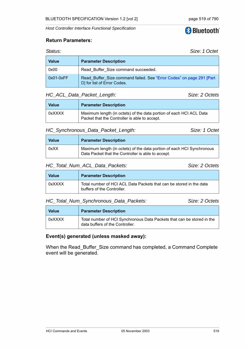
BLUETOOTH SPECIFICATION Version 1.2 [vol 2] page 519 of 790
Host Controller Interface Functional Specification
Return Parameters:
Status: Size: 1 Octet
HC_ACL_Data_Packet_Length: Size: 2 Octets
HC_Synchronous_Data_Packet_Length: Size: 1 Octet
HC_Total_Num_ACL_Data_Packets: Size: 2 Octets
HC_Total_Num_Synchronous_Data_Packets: Size: 2 Octets
Event(s) generated (unless masked away):
When the Read_Buffer_Size command has completed, a Command Complete event will be generated.
Value Parameter Description
0x00 Read_Buffer_Size command succeeded.
0x01-0xFF Read_Buffer_Size command failed. See “Error Codes” on page 291 [Part D] for list of Error Codes.
Value Parameter Description
0xXXXX Maximum length (in octets) of the data portion of each HCI ACL Data Packet that the Controller is able to accept.
Value Parameter Description
0xXX Maximum length (in octets) of the data portion of each HCI Synchronous Data Packet that the Controller is able to accept.
Value Parameter Description
0xXXXX Total number of HCI ACL Data Packets that can be stored in the data buffers of the Controller.
Value Parameter Description
0xXXXX Total number of HCI Synchronous Data Packets that can be stored in the data buffers of the Controller.
HCI Commands and Events 05 November 2003 519
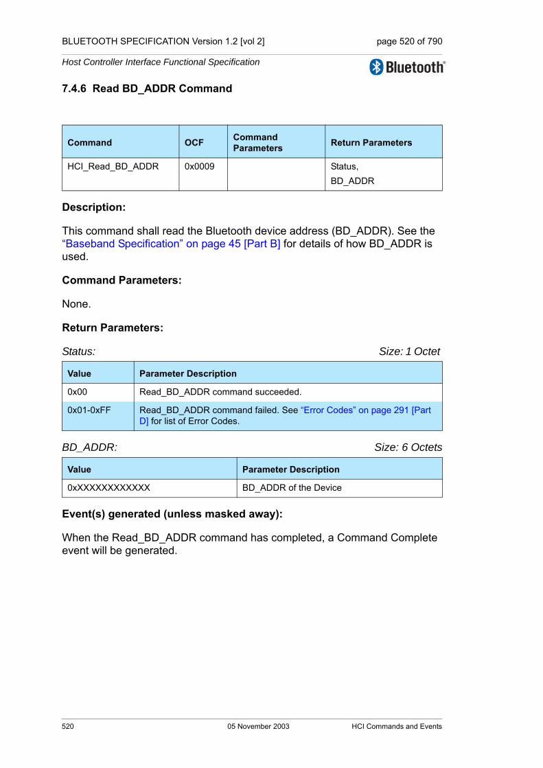
BLUETOOTH SPECIFICATION Version 1.2 [vol 2] page 520 of 790
Host Controller Interface Functional Specification
7.4.6 Read BD_ADDR Command
Description:
This command shall read the Bluetooth device address (BD_ADDR). See the “Baseband Specification” on page 45 [Part B] for details of how BD_ADDR is used.
Command Parameters:
None.
Return Parameters:
Status: Size: 1 Octet
BD_ADDR: Size: 6 Octets
Event(s) generated (unless masked away):
When the Read_BD_ADDR command has completed, a Command Complete event will be generated.
Command OCF Command Parameters Return Parameters
HCI_Read_BD_ADDR 0x0009 Status,BD_ADDR
Value Parameter Description
0x00 Read_BD_ADDR command succeeded.
0x01-0xFF Read_BD_ADDR command failed. See “Error Codes” on page 291 [Part D] for list of Error Codes.
Value Parameter Description
0xXXXXXXXXXXXX BD_ADDR of the Device
520 05 November 2003 HCI Commands and Events
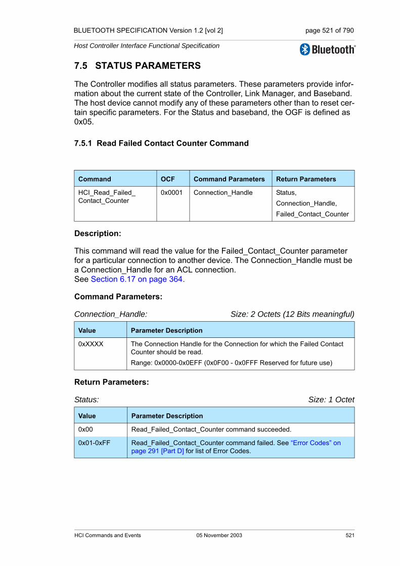
BLUETOOTH SPECIFICATION Version 1.2 [vol 2] page 521 of 790
Host Controller Interface Functional Specification
7.5 STATUS PARAMETERS
The Controller modifies all status parameters. These parameters provide infor-mation about the current state of the Controller, Link Manager, and Baseband. The host device cannot modify any of these parameters other than to reset cer-tain specific parameters. For the Status and baseband, the OGF is defined as 0x05.
7.5.1 Read Failed Contact Counter Command
Description:
This command will read the value for the Failed_Contact_Counter parameter for a particular connection to another device. The Connection_Handle must be a Connection_Handle for an ACL connection. See Section 6.17 on page 364.
Command Parameters:
Connection_Handle: Size: 2 Octets (12 Bits meaningful)
Return Parameters:
Status: Size: 1 Octet
Command OCF Command Parameters Return Parameters
HCI_Read_Failed_Contact_Counter
0x0001 Connection_Handle Status,Connection_Handle,Failed_Contact_Counter
Value Parameter Description
0xXXXX The Connection Handle for the Connection for which the Failed Contact Counter should be read.Range: 0x0000-0x0EFF (0x0F00 - 0x0FFF Reserved for future use)
Value Parameter Description
0x00 Read_Failed_Contact_Counter command succeeded.
0x01-0xFF Read_Failed_Contact_Counter command failed. See “Error Codes” on page 291 [Part D] for list of Error Codes.
HCI Commands and Events 05 November 2003 521

BLUETOOTH SPECIFICATION Version 1.2 [vol 2] page 522 of 790
Host Controller Interface Functional Specification
Connection_Handle: Size: 2 Octets (12 Bits meaningful)
Failed_Contact_Counter: Size: 2 Octets
Event(s) generated (unless masked away):
When the Read_Failed_Contact_Counter command has completed, a Com-mand Complete event will be generated.
Value Parameter Description
0xXXXX The Connection Handle for the Connection for which the Failed Contact Counter has been read.Range: 0x0000-0x0EFF (0x0F00 - 0x0FFF Reserved for future use)
Value Parameter Description
0xXXXX Number of consecutive failed contacts for a connection corresponding to the connection handle.
522 05 November 2003 HCI Commands and Events

BLUETOOTH SPECIFICATION Version 1.2 [vol 2] page 523 of 790
Host Controller Interface Functional Specification
7.5.2 Reset Failed Contact Counter Command
Description:
This command will reset the value for the Failed_Contact_Counter parameter for a particular connection to another device. The Connection_Handle must be a Connection_Handle for an ACL connection. See Section 6.17 on page 364.
Command Parameters:
Connection_Handle: Size: 2 Octets (12 Bits meaningful)
Return Parameters:
Status: Size: 1 Octet
Connection_Handle: Size: 2 Octets (12 Bits meaningful)
Event(s) generated (unless masked away):
When the Reset_Failed_Contact_Counter command has completed, a Com-mand Complete event will be generated.
Command OCF Command Parameters Return Parameters
HCI_Reset_Failed_Contact_Counter
0x0002 Connection_Handle Status,Connection_Handle
Value Parameter Description
0xXXXX The Connection Handle for the Connection for which the Failed Contact Counter should be reset.Range: 0x0000-0x0EFF (0x0F00 - 0x0FFF Reserved for future use)
Value Parameter Description
0x00 Reset_Failed_Contact_Counter command succeeded.
0x01-0xFF Reset_Failed_Contact_Counter command failed. See “Error Codes” on page 291 [Part D] for list of Error Codes.
Value Parameter Description
0xXXXX The Connection Handle for the Connection for which the Failed Contact Counter has been reset.Range: 0x0000-0x0EFF (0x0F00 - 0x0FFF Reserved for future use)
HCI Commands and Events 05 November 2003 523
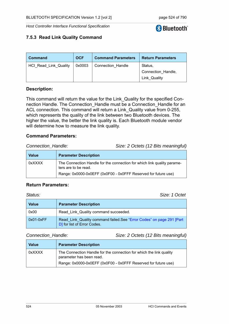
BLUETOOTH SPECIFICATION Version 1.2 [vol 2] page 524 of 790
Host Controller Interface Functional Specification
7.5.3 Read Link Quality Command
Description:
This command will return the value for the Link_Quality for the specified Con-nection Handle. The Connection_Handle must be a Connection_Handle for an ACL connection. This command will return a Link_Quality value from 0-255, which represents the quality of the link between two Bluetooth devices. The higher the value, the better the link quality is. Each Bluetooth module vendor will determine how to measure the link quality.
Command Parameters:
Connection_Handle: Size: 2 Octets (12 Bits meaningful)
Return Parameters:
Status: Size: 1 Octet
Connection_Handle: Size: 2 Octets (12 Bits meaningful)
Command OCF Command Parameters Return Parameters
HCI_Read_Link_Quality 0x0003 Connection_Handle Status,Connection_Handle,Link_Quality
Value Parameter Description
0xXXXX The Connection Handle for the connection for which link quality parame-ters are to be read.Range: 0x0000-0x0EFF (0x0F00 - 0x0FFF Reserved for future use)
Value Parameter Description
0x00 Read_Link_Quality command succeeded.
0x01-0xFF Read_Link_Quality command failed.See “Error Codes” on page 291 [Part D] for list of Error Codes.
Value Parameter Description
0xXXXX The Connection Handle for the connection for which the link quality parameter has been read.Range: 0x0000-0x0EFF (0x0F00 - 0x0FFF Reserved for future use)
524 05 November 2003 HCI Commands and Events
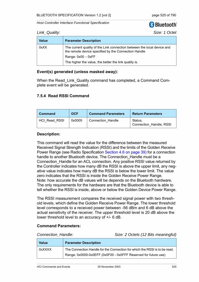
BLUETOOTH SPECIFICATION Version 1.2 [vol 2] page 525 of 790
Host Controller Interface Functional Specification
Link_Quality: Size: 1 Octet
Event(s) generated (unless masked away):
When the Read_Link_Quality command has completed, a Command Com-plete event will be generated.
7.5.4 Read RSSI Command
Description:
This command will read the value for the difference between the measured Received Signal Strength Indication (RSSI) and the limits of the Golden Receive Power Range (see Radio Specification Section 4.6 on page 39) for a connection handle to another Bluetooth device. The Connection_Handle must be a Connection_Handle for an ACL connection. Any positive RSSI value returned by the Controller indicates how many dB the RSSI is above the upper limit, any neg-ative value indicates how many dB the RSSI is below the lower limit. The value zero indicates that the RSSI is inside the Golden Receive Power Range. Note: how accurate the dB values will be depends on the Bluetooth hardware. The only requirements for the hardware are that the Bluetooth device is able to tell whether the RSSI is inside, above or below the Golden Device Power Range.
The RSSI measurement compares the received signal power with two thresh-old levels, which define the Golden Receive Power Range. The lower threshold level corresponds to a received power between -56 dBm and 6 dB above the actual sensitivity of the receiver. The upper threshold level is 20 dB above the lower threshold level to an accuracy of +/- 6 dB.
Command Parameters:
Connection_Handle: Size: 2 Octets (12 Bits meaningful)
Value Parameter Description
0xXX The current quality of the Link connection between the local device and the remote device specified by the Connection HandleRange: 0x00 – 0xFFThe higher the value, the better the link quality is.
Command OCF Command Parameters Return Parameters
HCI_Read_RSSI 0x0005 Connection_Handle Status,Connection_Handle, RSSI
Value Parameter Description
0xXXXX The Connection Handle for the Connection for which the RSSI is to be read. Range: 0x0000-0x0EFF (0x0F00 - 0x0FFF Reserved for future use)
HCI Commands and Events 05 November 2003 525

BLUETOOTH SPECIFICATION Version 1.2 [vol 2] page 526 of 790
Host Controller Interface Functional Specification
Return Parameters:
Status: Size: 1 Octet
Connection_Handle: Size: 2 Octets (12 Bits meaningful)
RSSI: Size: 1 Octet
Event(s) generated (unless masked away):
When the Read_RSSI command has completed, a Command Complete event will be generated.
Value Parameter Description
0x00 Read_RSSI command succeeded.
0x01-0xFF Read_RSSI command failed. See “Error Codes” on page 291 [Part D] for list of Error Codes.
Value Parameter Description
0xXXXX The Connection Handle for the Connection for which the RSSI has been read. Range: 0x0000-0x0EFF (0x0F00 - 0x0FFF Reserved for future use)
Value Parameter Description
N = 0xXX Size: 1 Octet (signed integer)
Range: -128 ≤ N ≤ 127
Units: dB
526 05 November 2003 HCI Commands and Events
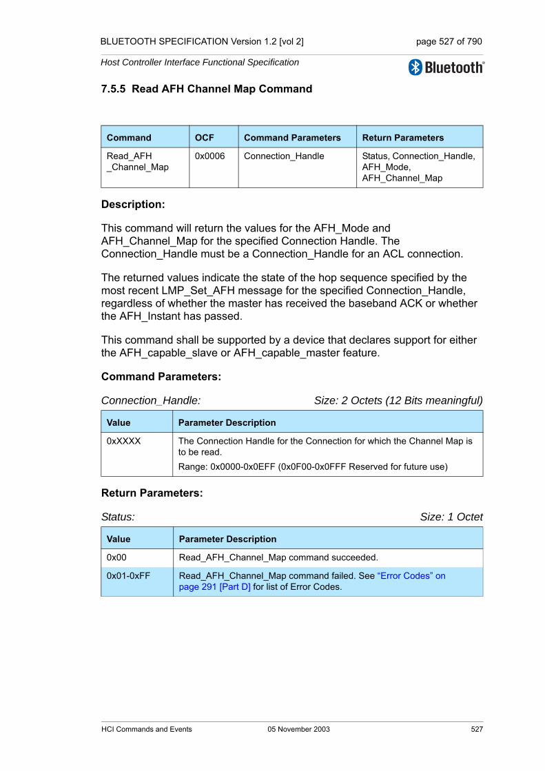
BLUETOOTH SPECIFICATION Version 1.2 [vol 2] page 527 of 790
Host Controller Interface Functional Specification
7.5.5 Read AFH Channel Map Command
Description:
This command will return the values for the AFH_Mode and AFH_Channel_Map for the specified Connection Handle. The Connection_Handle must be a Connection_Handle for an ACL connection.
The returned values indicate the state of the hop sequence specified by the most recent LMP_Set_AFH message for the specified Connection_Handle, regardless of whether the master has received the baseband ACK or whether the AFH_Instant has passed.
This command shall be supported by a device that declares support for either the AFH_capable_slave or AFH_capable_master feature.
Command Parameters:
Connection_Handle: Size: 2 Octets (12 Bits meaningful)
Return Parameters:
Status: Size: 1 Octet
Command OCF Command Parameters Return Parameters
Read_AFH_Channel_Map
0x0006 Connection_Handle Status, Connection_Handle, AFH_Mode, AFH_Channel_Map
Value Parameter Description
0xXXXX The Connection Handle for the Connection for which the Channel Map is to be read.Range: 0x0000-0x0EFF (0x0F00-0x0FFF Reserved for future use)
Value Parameter Description
0x00 Read_AFH_Channel_Map command succeeded.
0x01-0xFF Read_AFH_Channel_Map command failed. See “Error Codes” on page 291 [Part D] for list of Error Codes.
HCI Commands and Events 05 November 2003 527

BLUETOOTH SPECIFICATION Version 1.2 [vol 2] page 528 of 790
Host Controller Interface Functional Specification
Connection_Handle: Size: 2 Octets (12 Bits meaningful)
AFH_Mode: Size: 1 Octet
AFH_Channel_Map: Size: 10 Octets (79 Bits meaningful)
Event(s) generated (unless masked away):
When the Read_AFH_Channel_Map command has completed, a Command Complete event will be generated.
Value Parameter Description
0xXXXX The Connection Handle for the Connection for which the Channel Map is to be read.Range: 0x0000-0x0EFF (0x0F00-0x0FFF Reserved for future use)
Value Parameter Description
0x00 AFH disabled.
0x01 AFH enabled.
0x02-0xFF Reserved for future use.
Value Parameter Description
0xXXXXXXXXXXXXXXXXXXXX
If AFH_Mode is AFH enabled then this parameter contains 79 1-bit fields, otherwise the contents are reserved.
The nth such field (in the range 0 to 78) contains the value for channel n:Channel n is unused = 0Channel n is used = 1 Range: 0x00000000000000000000-0x7FFFFFFFFFFFFFFFFFFF (0x80000000000000000000-0xFFFFFFFFFFFFFFFFFFFF Reserved for future use)
528 05 November 2003 HCI Commands and Events
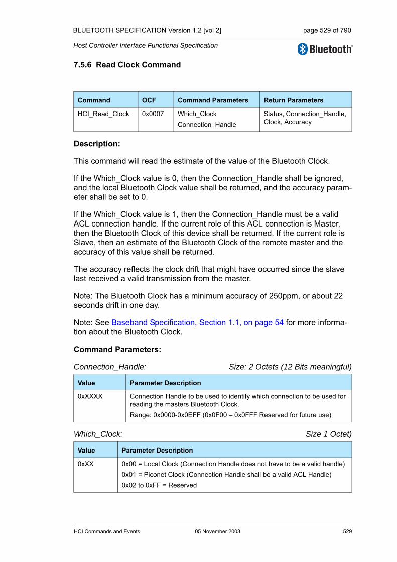
BLUETOOTH SPECIFICATION Version 1.2 [vol 2] page 529 of 790
Host Controller Interface Functional Specification
7.5.6 Read Clock Command
Description:
This command will read the estimate of the value of the Bluetooth Clock.
If the Which_Clock value is 0, then the Connection_Handle shall be ignored, and the local Bluetooth Clock value shall be returned, and the accuracy param-eter shall be set to 0.
If the Which_Clock value is 1, then the Connection_Handle must be a valid ACL connection handle. If the current role of this ACL connection is Master, then the Bluetooth Clock of this device shall be returned. If the current role is Slave, then an estimate of the Bluetooth Clock of the remote master and the accuracy of this value shall be returned.
The accuracy reflects the clock drift that might have occurred since the slave last received a valid transmission from the master.
Note: The Bluetooth Clock has a minimum accuracy of 250ppm, or about 22 seconds drift in one day.
Note: See Baseband Specification, Section 1.1, on page 54 for more informa-tion about the Bluetooth Clock.
Command Parameters:
Connection_Handle: Size: 2 Octets (12 Bits meaningful)
Which_Clock: Size 1 Octet)
Command OCF Command Parameters Return Parameters
HCI_Read_Clock 0x0007 Which_ClockConnection_Handle
Status, Connection_Handle, Clock, Accuracy
Value Parameter Description
0xXXXX Connection Handle to be used to identify which connection to be used for reading the masters Bluetooth Clock.Range: 0x0000-0x0EFF (0x0F00 – 0x0FFF Reserved for future use)
Value Parameter Description
0xXX 0x00 = Local Clock (Connection Handle does not have to be a valid handle)0x01 = Piconet Clock (Connection Handle shall be a valid ACL Handle)0x02 to 0xFF = Reserved
HCI Commands and Events 05 November 2003 529

BLUETOOTH SPECIFICATION Version 1.2 [vol 2] page 530 of 790
Host Controller Interface Functional Specification
Return Parameters:
Status: Size: 1 Octet
Connection_Handle: Size: 2 Octets (12 Bits meaningful)
Clock: Size: 4 Octets (28 bits meaningful)
Accuracy: Size: 2 Octets
Event(s) generated (unless masked away):
When the Read_Clock command has completed, a Command Complete event will be generated.
Value Parameter Description
0x00 Read_BD_CLOCK command succeeded.
0x01 – 0xFF Read_BD_CLOCK command failed. See “Error Codes” on page 291 [Part D] for list of Error Codes.
Value Parameter Description
0xXXXX The Connection Handle for the Connection for which the master clock has been read. If the Which_Clock was 0, then the Connection_Handle shall be set to 0 and ignored upon receiptRange: 0x0000-0x0EFF (0x0F00 – 0x0FFF Reserved for future use)
Value Parameter Description
0xXXXXXXXX Bluetooth Clock of the device requested.
Value Parameter Description
0xXX +/- maximum Bluetooth Clock error. Value of 0xFFFF means Unknown.Accuracy = +/- N * 0.3125 msec (1 Bluetooth Clock)Range for N: 0x00-0xFFFE, 0xFFFFTime Range for N: 0 - 20479.375 sec
530 05 November 2003 HCI Commands and Events
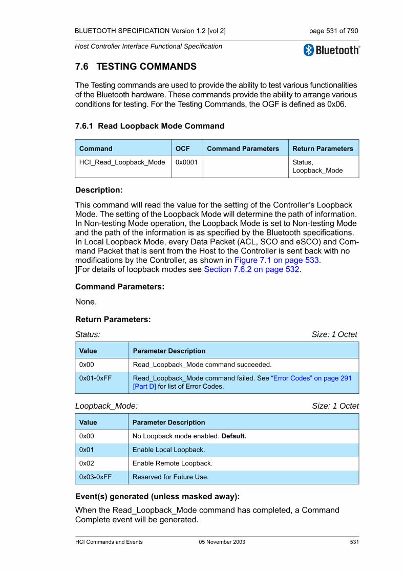
BLUETOOTH SPECIFICATION Version 1.2 [vol 2] page 531 of 790
Host Controller Interface Functional Specification
7.6 TESTING COMMANDS
The Testing commands are used to provide the ability to test various functionalities of the Bluetooth hardware. These commands provide the ability to arrange various conditions for testing. For the Testing Commands, the OGF is defined as 0x06.
7.6.1 Read Loopback Mode Command
Description:
This command will read the value for the setting of the Controller’s Loopback Mode. The setting of the Loopback Mode will determine the path of information. In Non-testing Mode operation, the Loopback Mode is set to Non-testing Mode and the path of the information is as specified by the Bluetooth specifications. In Local Loopback Mode, every Data Packet (ACL, SCO and eSCO) and Com-mand Packet that is sent from the Host to the Controller is sent back with no modifications by the Controller, as shown in Figure 7.1 on page 533. ]For details of loopback modes see Section 7.6.2 on page 532.
Command Parameters:
None.
Return Parameters:
Status: Size: 1 Octet
Loopback_Mode: Size: 1 Octet
Event(s) generated (unless masked away): When the Read_Loopback_Mode command has completed, a Command Complete event will be generated.
Command OCF Command Parameters Return Parameters
HCI_Read_Loopback_Mode 0x0001 Status,Loopback_Mode
Value Parameter Description
0x00 Read_Loopback_Mode command succeeded.
0x01-0xFF Read_Loopback_Mode command failed. See “Error Codes” on page 291 [Part D] for list of Error Codes.
Value Parameter Description
0x00 No Loopback mode enabled. Default.
0x01 Enable Local Loopback.
0x02 Enable Remote Loopback.
0x03-0xFF Reserved for Future Use.
HCI Commands and Events 05 November 2003 531

BLUETOOTH SPECIFICATION Version 1.2 [vol 2] page 532 of 790
Host Controller Interface Functional Specification
7.6.2 Write Loopback Mode Command
Description:
This command will write the value for the setting of the Controller’s Loopback Mode. The setting of the Loopback Mode will determine the path of information. In Non-testing Mode operation, the Loopback Mode is set to Non-testing Mode and the path of the information as specified by the Bluetooth specifications. In Local Loopback Mode, every Data Packet (ACL, SCO and eSCO) and Com-mand Packet that is sent from the Host to the Controller is sent back with no modifications by the Controller, as shown in Figure 7.1 on page 533.
When the Bluetooth Host Controller enters Local Loopback Mode, it shall respond with one to four connection handles, one for an ACL connection and zero to three for synchronous connections. The Host should use these connec-tion handles when sending data in Local Loopback Mode. The number of con-nection handles returned for synchronous connections (between zero and three) is implementation specific. When in Local Loopback Mode, the Controller loops back commands and data to the Host. The Loopback Command event is used to loop back commands that the Host sends to the Controller.
There are some commands that are not looped back in Local Loopback Mode: Reset, Set_Controller_To_Host_Flow_Control, Host_Buffer_Size, Host_Number_Of_Completed_Packets, Read_Buffer_Size, Read_Loopback_Mode and Write_Loopback_Mode. These commands should be executed in the way they are normally executed. The commands Reset and Write_Loopback_Mode can be used to exit local loopback mode.
If Write_Loopback_Mode is used to exit Local Loopback Mode, Disconnection Complete events corresponding to the Connection Complete events that were sent when entering Local Loopback Mode should be sent to the Host. Further-more, no connections are allowed in Local Loopback mode. If there is a con-nection, and there is an attempt to set the device to Local Loopback Mode, the attempt will be refused. When the device is in Local Loopback Mode, the Con-troller will refuse incoming connection attempts. This allows the Host Controller Transport Layer to be tested without any other variables.
If a device is set to Remote Loopback Mode, it will send back all data (ACL, SCO and eSCO) that comes over the air. It will only allow a maximum of one ACL connection and three synchronous connections, and these shall all be to the same remote device. If there are existing connections to a remote device and there is an attempt to set the local device to Remote Loopback Mode, the attempt shall be refused.
Command OCF Command Parameters Return Parameters
HCI_Write_Loopback_Mode 0x0002 Loopback_Mode Status
532 05 November 2003 HCI Commands and Events
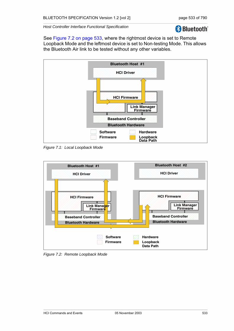
BLUETOOTH SPECIFICATION Version 1.2 [vol 2] page 533 of 790
Host Controller Interface Functional Specification
See Figure 7.2 on page 533, where the rightmost device is set to Remote Loopback Mode and the leftmost device is set to Non-testing Mode. This allows the Bluetooth Air link to be tested without any other variables.
Figure 7.1: Local Loopback Mode
Figure 7.2: Remote Loopback Mode
Bluetooth Host #1
Bluetooth Hardware
HCI Driver
HCI Firmware
Baseband Controller
SoftwareFirmware
Hardware
Link ManagerFirmware
LoopbackData Path
Bluetooth Host #1
Bluetooth Hardware
HCI Driver
HCI Firmware
Baseband Controller
SoftwareFirmware
HardwareLoopbackData Path
Bluetooth Host #2
Bluetooth Hardware
HCI Driver
HCI Firmware
Baseband Controller
Link ManagerFirmware
Link ManagerFirmware
HCI Commands and Events 05 November 2003 533

BLUETOOTH SPECIFICATION Version 1.2 [vol 2] page 534 of 790
Host Controller Interface Functional Specification
Command Parameters:
Loopback_Mode: Size: 1 Octet
Return Parameters:
Status: Size: 1 Octet
Event(s) generated (unless masked away):
When the Write_Loopback_Mode command has completed, a Command Complete event will be generated.
Value Parameter Description
0x00 No Loopback mode enabled. Default.
0x01 Enable Local Loopback.
0x02 Enable Remote Loopback.
0x03-0xFF Reserved for Future Use.
Value Parameter Description
0x00 Write_Loopback_Mode command succeeded.
0x01-0xFF Write_Loopback_Mode command failed. See “Error Codes” on page 291 [Part D] for list of Error Codes.
534 05 November 2003 HCI Commands and Events

BLUETOOTH SPECIFICATION Version 1.2 [vol 2] page 535 of 790
Host Controller Interface Functional Specification
7.6.3 Enable Device Under Test Mode Command
Description:
The Enable_Device_Under_Test_Mode command will allow the local Bluetooth module to enter test mode via LMP test commands. For details see “Link Man-ager Protocol” on page 189 [Part C]. The Host issues this command when it wants the local device to be the DUT for the Testing scenarios as described in the “Test Methodology” on page 233[vol. 3]. When the Controller receives this command, it will complete the command with a Command Complete event. The Controller functions as normal until the remote tester issues the LMP test command to place the local device into Device Under Test mode. To disable and exit the Device Under Test Mode, the Host can issue the HCI_Reset com-mand. This command prevents remote Bluetooth devices from causing the local Bluetooth device to enter test mode without first issuing this command.
Command Parameters:
None.
Return Parameters:
Status: Size: 1 Octet
Event(s) generated (unless masked away):
When the Enter_Device_Under_Test_Mode command has completed, a Command Complete event will be generated.
Command OCF Command Parameters Return Parameters
HCI_Enable_Device_Under_Test_Mode
0x0003 Status
Value Parameter Description
0x00 Enter_Device_Under_Test_Mode command succeeded.
0x01-0xFF Enter_Device_Under_Test_Mode command failed. See “Error Codes” on page 291 [Part D] for list of Error Codes.
HCI Commands and Events 05 November 2003 535

BLUETOOTH SPECIFICATION Version 1.2 [vol 2] page 536 of 790
Host Controller Interface Functional Specification
536 05 November 2003 HCI Commands and Events

BLUETOOTH SPECIFICATION Version 1.2 [vol 2] page 537 of 790
Host Controller Interface Functional Specification
7.7 EVENTS
7.7.1 Inquiry Complete Event
Description:
The Inquiry Complete event indicates that the Inquiry is finished. This event contains a status parameter, which is used to indicate if the Inquiry completed successfully or if the Inquiry was not completed.
Event Parameters:
Status: Size: 1 Octet
Event Event Code Event Parameters
Inquiry Complete 0x01 Status
Value Parameter Description
0x00 Inquiry command completed successfully.
0x01-0xFF Inquiry command failed. See “Error Codes” on page 291 [Part D] for list of Error Codes.
HCI Commands and Events 05 November 2003 537

BLUETOOTH SPECIFICATION Version 1.2 [vol 2] page 538 of 790
Host Controller Interface Functional Specification
7.7.2 Inquiry Result Event
Description:
The Inquiry Result event indicates that a Bluetooth device or multiple Bluetooth devices have responded so far during the current Inquiry process. This event will be sent from the Controller to the Host as soon as an Inquiry Response from a remote device is received if the remote device supports only mandatory paging scheme. The Controller may queue these Inquiry Responses and send multiple Bluetooth devices information in one Inquiry Result event. The event can be used to return one or more Inquiry responses in one event.
Event Parameters:
Num_Responses: Size: 1 Octet
BD_ADDR[i]: Size: 6 Octets * Num_Responses
Event Event Code Event Parameters
Inquiry Result 0x02 Num_Responses,BD_ADDR[i],Page_Scan_Repetition_Mode[i],Page_Scan_Period_Mode[i],Reserved[i],Class_of_Device[i]Clock_Offset[i]
Value Parameter Description
0xXX Number of responses from the Inquiry.
Value Parameter Description
0xXXXXXXXXXXXX
BD_ADDR for each device which responded.
538 05 November 2003 HCI Commands and Events
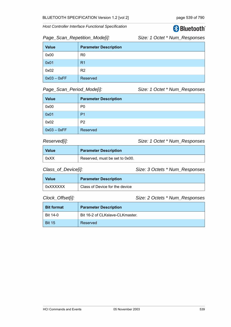
BLUETOOTH SPECIFICATION Version 1.2 [vol 2] page 539 of 790
Host Controller Interface Functional Specification
Page_Scan_Repetition_Mode[i]: Size: 1 Octet * Num_Responses
Page_Scan_Period_Mode[i]: Size: 1 Octet * Num_Responses
Reserved[i]: Size: 1 Octet * Num_Responses
Class_of_Device[i]: Size: 3 Octets * Num_Responses
Clock_Offset[i]: Size: 2 Octets * Num_Responses
Value Parameter Description
0x00 R0
0x01 R1
0x02 R2
0x03 – 0xFF Reserved
Value Parameter Description
0x00 P0
0x01 P1
0x02 P2
0x03 – 0xFF Reserved
Value Parameter Description
0xXX Reserved, must be set to 0x00.
Value Parameter Description
0xXXXXXX Class of Device for the device
Bit format Parameter Description
Bit 14-0 Bit 16-2 of CLKslave-CLKmaster.
Bit 15 Reserved
HCI Commands and Events 05 November 2003 539

BLUETOOTH SPECIFICATION Version 1.2 [vol 2] page 540 of 790
Host Controller Interface Functional Specification
7.7.3 Connection Complete Event
Description:
The Connection Complete event indicates to both of the Hosts forming the con-nection that a new connection has been established. This event also indicates to the Host, which issued the Create Connection, or Accept_Connection_Request or Reject_Connection_Request command and then received a Com-mand Status event, if the issued command failed or was successful.
Event Parameters:
Status: Size: 1 Octet
Connection_Handle: Size: 2 Octets (12 Bits meaningful)
BD_ADDR: Size: 6 Octets
Link_Type: Size: 1 Octet
Event Event Code Event Parameters
Connection Complete 0x03 Status,Connection_Handle,BD_ADDR,Link_Type,Encryption_Mode
Value Parameter Description
0x00 Connection successfully completed.
0x01-0xFF Connection failed to Complete. See “Error Codes” on page 291 [Part D] for list of Error Codes.
Value Parameter Description
0xXXXX Connection Handle to be used to identify a connection between two Blue-tooth devices. The Connection Handle is used as an identifier for transmit-ting and receiving voice or data.Range: 0x0000-0x0EFF (0x0F00 - 0x0FFF Reserved for future use)
Value Parameter Description
0xXXXXXXXXXXXX BD_ADDR of the other connected Device forming the connection.
Value Parameter Description
0x00 SCO connection.
0x01 ACL connection (Data Channels).
0x02-0xFF Reserved for future use.
540 05 November 2003 HCI Commands and Events

BLUETOOTH SPECIFICATION Version 1.2 [vol 2] page 541 of 790
Host Controller Interface Functional Specification
Encryption_Mode: Size: 1 Octet
7.7.4 Connection Request Event
Description:
The Connection Request event is used to indicate that a new incoming connec-tion is trying to be established. The connection may either be accepted or rejected. If this event is masked away and there is an incoming connection attempt and the Controller is not set to auto-accept this connection attempt, the Controller will automatically refuse the connection attempt. When the Host receives this event and the link type parameter is ACL, it should respond with either an Accept_Connection_Request or Reject_Connection_Request com-mand before the timer Conn_Accept_Timeout expires. If the link type is SCO or eSCO, the Host should reply with the Accept_Synchronous_Connection_Request or the Reject_Synchronous_Connection_Request Command. If the link type is SCO, the host may respond with Accept_Connection_Request. If the Event is responded to with Accept_Connection_Request, then the default parameter settings of the Accept_Synchronous_Connection_Request (see Section 7.1.27 on page 415) should be used by the local LM when negotiating the SCO or eSCO link parameters. In that case, the Connection_Complete Event and not the Synchronous_Connection_Complete Event, shall be returned on completion of the connection.
Event Parameters:
BD_ADDR: Size: 6 Octets
Value Parameter Description
See Section 6.16 on page 363.
Event Event Code Event Parameters
Connection Request 0x04 BD_ADDR,Class_of_Device,Link_Type
Value Parameter Description
0xXXXXXXXXXXXX BD_ADDR of the device that requests the connection.
HCI Commands and Events 05 November 2003 541
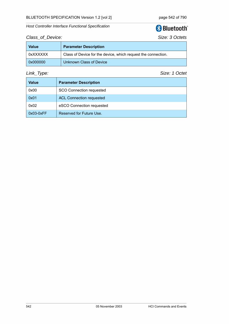
BLUETOOTH SPECIFICATION Version 1.2 [vol 2] page 542 of 790
Host Controller Interface Functional Specification
Class_of_Device: Size: 3 Octets
Link_Type: Size: 1 Octet
Value Parameter Description
0xXXXXXX Class of Device for the device, which request the connection.
0x000000 Unknown Class of Device
Value Parameter Description
0x00 SCO Connection requested
0x01 ACL Connection requested
0x02 eSCO Connection requested
0x03-0xFF Reserved for Future Use.
542 05 November 2003 HCI Commands and Events
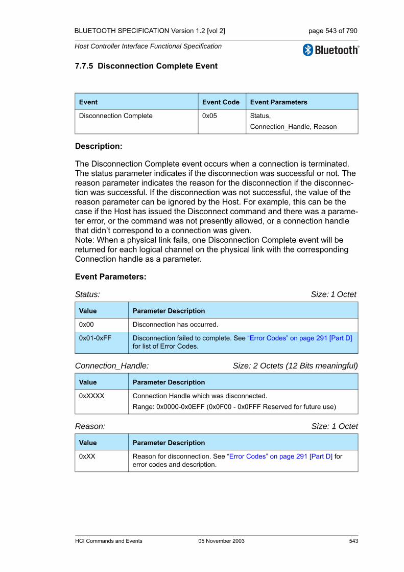
BLUETOOTH SPECIFICATION Version 1.2 [vol 2] page 543 of 790
Host Controller Interface Functional Specification
7.7.5 Disconnection Complete Event
Description:
The Disconnection Complete event occurs when a connection is terminated. The status parameter indicates if the disconnection was successful or not. The reason parameter indicates the reason for the disconnection if the disconnec-tion was successful. If the disconnection was not successful, the value of the reason parameter can be ignored by the Host. For example, this can be the case if the Host has issued the Disconnect command and there was a parame-ter error, or the command was not presently allowed, or a connection handle that didn’t correspond to a connection was given. Note: When a physical link fails, one Disconnection Complete event will be returned for each logical channel on the physical link with the corresponding Connection handle as a parameter.
Event Parameters:
Status: Size: 1 Octet
Connection_Handle: Size: 2 Octets (12 Bits meaningful)
Reason: Size: 1 Octet
Event Event Code Event Parameters
Disconnection Complete 0x05 Status,Connection_Handle, Reason
Value Parameter Description
0x00 Disconnection has occurred.
0x01-0xFF Disconnection failed to complete. See “Error Codes” on page 291 [Part D] for list of Error Codes.
Value Parameter Description
0xXXXX Connection Handle which was disconnected.Range: 0x0000-0x0EFF (0x0F00 - 0x0FFF Reserved for future use)
Value Parameter Description
0xXX Reason for disconnection. See “Error Codes” on page 291 [Part D] for error codes and description.
HCI Commands and Events 05 November 2003 543

BLUETOOTH SPECIFICATION Version 1.2 [vol 2] page 544 of 790
Host Controller Interface Functional Specification
7.7.6 Authentication Complete Event
Description:
The Authentication Complete event occurs when authentication has been com-pleted for the specified connection. The Connection_Handle must be a Connection_Handle for an ACL connection.
Event Parameters:
Status: Size: 1 Octet
Connection_Handle: Size: 2 Octets (12 Bits meaningful)
Event Event Code Event Parameters
Authentication Complete 0x06 Status, Connection_Handle
Value Parameter Description
0x00 Authentication Request successfully completed.
0x01-0xFF Authentication Request failed to complete. See “Error Codes” on page 291 [Part D] for list of Error Codes.
Value Parameter Description
0xXXXX Connection Handle for which Authentication has been performed. Range: 0x0000-0x0EFF (0x0F00 - 0x0FFF Reserved for future use)
544 05 November 2003 HCI Commands and Events

BLUETOOTH SPECIFICATION Version 1.2 [vol 2] page 545 of 790
Host Controller Interface Functional Specification
7.7.7 Remote Name Request Complete Event
Description:
The Remote Name Request Complete event is used to indicate that a remote name request has been completed. The Remote_Name event parameter is a UTF-8 encoded string with up to 248 octets in length. The Remote_Name event parameter will be null-terminated (0x00) if the UTF-8 encoded string is less than 248 octets. The BD_ADDR event parameter is used to identify which device the user-friendly name was obtained from. Note: the Remote_Name Parameter is a string parameter. Endianess does therefore not apply to the Remote_Name Parameter. The first octet of the name is received first.
Event Parameters:
Status: Size: 1 Octet
BD_ADDR: Size: 6 Octets
Remote_Name: Size: 248 Octets
Event Event Code Event Parameters
Remote Name Request Complete 0x07 Status,BD_ADDR, Remote_Name
Value Parameter Description
0x00 Remote_Name_Request command succeeded.
0x01-0xFF Remote_Name_Request command failed. See “Error Codes” on page 291 [Part D] for list of Error Codes.
Value Parameter Description
0xXXXXXXXXXXXX BD_ADDR for the device whose name was requested.
Value Parameter Description
Name[248] A UTF-8 encoded user-friendly descriptive name for the remote device. If the name contained in the parameter is shorter than 248 octets, the end of the name is indicated by a NULL octet (0x00), and the following octets (to fill up 248 octets, which is the length of the parameter) do not have valid values.
HCI Commands and Events 05 November 2003 545

BLUETOOTH SPECIFICATION Version 1.2 [vol 2] page 546 of 790
Host Controller Interface Functional Specification
7.7.8 Encryption Change Event
Description:
The Encryption Change event is used to indicate that the change in the encryp-tion has been completed for the Connection Handle specified by the Connection_Handle event parameter. The Connection_Handle will be a Connection_Handle for an ACL connection. The Encryption_Enable event parameter specifies the new Encryption Enable for the Connection Handle specified by the Connection_Handle event parameter. This event will occur on both devices to notify the Hosts when Encryption has changed for the specified Connection Handle between two devices.
Event Parameters:
Status: Size: 1 Octet
Connection_Handle: Size: 2 Octets (12 Bits meaningful)
Encryption_Enable: Size: 1 Octet
Event Event Code Event Parameters
Encryption Change 0x08 Status,Connection_Handle,Encryption_Enable
Value Parameter Description
0x00 Encryption Change has occurred.
0x01-0xFF Encryption Change failed. See “Error Codes” on page 291 [Part D] for list of Error Codes.
Value Parameter Description
0xXXXX Connection Handle for which the link layer encryption has been enabled/disabled for all Connection Handles with the same Bluetooth device end-point as the specified Connection Handle.Range: 0x0000-0x0EFF (0x0F00 - 0x0FFF Reserved for future use)
Value Parameter Description
0x00 Link Level Encryption is OFF.
0x01 Link Level Encryption is ON.
546 05 November 2003 HCI Commands and Events

BLUETOOTH SPECIFICATION Version 1.2 [vol 2] page 547 of 790
Host Controller Interface Functional Specification
7.7.9 Change Connection Link Key Complete Event
Description:
The Change Connection Link Key Complete event is used to indicate that the change in the Link Key for the Connection Handle specified by the Connection_Handle event parameter has been completed. The Connection_Handle will be a Connection_Handle for an ACL connection. The Change Connection Link Key Complete event is sent only to the Host which issued the Change_Connection_Link_Key command.
Event Parameters:
Status: Size: 1 Octet
Connection_Handle: Size: 2 Octets (12 Bits meaningful)
Event Event Code Event Parameters
Change Connection Link Key Complete 0x09 Status, Connection_Handle
Value Parameter Description
0x00 Change_Connection_Link_Key command succeeded.
0x01-0xFF Change_Connection_Link_Key command failed. See “Error Codes” on page 291 [Part D] for list of Error Codes.
Value Parameter Description
0xXXXX Connection Handle which the Link Key has been change for all Connec-tion Handles with the same Bluetooth device end point as the specified Connection Handle.Range: 0x0000-0x0EFF (0x0F00 - 0x0FFF Reserved for future use)
HCI Commands and Events 05 November 2003 547

BLUETOOTH SPECIFICATION Version 1.2 [vol 2] page 548 of 790
Host Controller Interface Functional Specification
7.7.10 Master Link Key Complete Event
Description:
The Master Link Key Complete event is used to indicate that the Link Key man-aged by the master of the piconet has been changed. The Connection_Handle will be a Connection_Handle for an ACL connection. The link key used for the connection will be the temporary link key of the master device or the semi-permanent link key indicated by the Key_Flag. The Key_Flag event parameter is used to indicate which Link Key (temporary link key of the Master, or the semi-permanent link keys) is now being used in the piconet. Note: for a master, the change from a semi-permanent Link Key to temporary Link Key will affect all Connection Handles related to the piconet. For a slave, this change affects only this particular connection handle. A temporary link key must be used when both broadcast and point-to-point traffic shall be encrypted.
Event Parameters:
Status: Size: 1 Octet
Connection_Handle: Size: 2 Octets (12 Bits meaningful)
Key_Flag: Size: 1 Octet
Event Event Code Event Parameters
Master Link Key Complete 0x0A Status,Connection_Handle, Key_Flag
Value Parameter Description
0x00 Master_Link_Key command succeeded.
0x01-0xFF Master_Link_Key command failed. See “Error Codes” on page 291 [Part D] for list of Error Codes.
Value Parameter Description
0xXXXX Connection Handle for which the Link Key has been changed for all devices in the same piconet.Range: 0x0000-0x0EFF (0x0F00 - 0x0FFF Reserved for future use)
Value Parameter Description
0x00 Using Semi-permanent Link Key.
0x01 Using Temporary Link Key.
548 05 November 2003 HCI Commands and Events
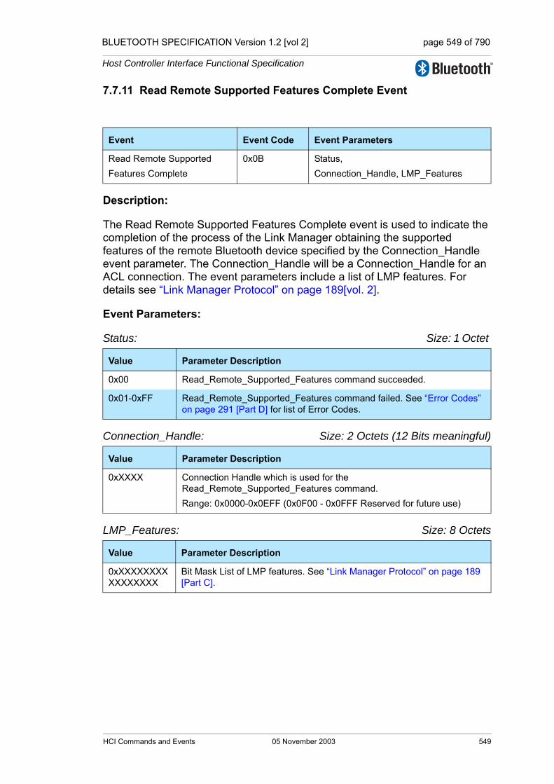
BLUETOOTH SPECIFICATION Version 1.2 [vol 2] page 549 of 790
Host Controller Interface Functional Specification
7.7.11 Read Remote Supported Features Complete Event
Description:
The Read Remote Supported Features Complete event is used to indicate the completion of the process of the Link Manager obtaining the supported features of the remote Bluetooth device specified by the Connection_Handle event parameter. The Connection_Handle will be a Connection_Handle for an ACL connection. The event parameters include a list of LMP features. For details see “Link Manager Protocol” on page 189[vol. 2].
Event Parameters:
Status: Size: 1 Octet
Connection_Handle: Size: 2 Octets (12 Bits meaningful)
LMP_Features: Size: 8 Octets
Event Event Code Event Parameters
Read Remote Supported Features Complete
0x0B Status,Connection_Handle, LMP_Features
Value Parameter Description
0x00 Read_Remote_Supported_Features command succeeded.
0x01-0xFF Read_Remote_Supported_Features command failed. See “Error Codes” on page 291 [Part D] for list of Error Codes.
Value Parameter Description
0xXXXX Connection Handle which is used for the Read_Remote_Supported_Features command.Range: 0x0000-0x0EFF (0x0F00 - 0x0FFF Reserved for future use)
Value Parameter Description
0xXXXXXXXXXXXXXXXX
Bit Mask List of LMP features. See “Link Manager Protocol” on page 189 [Part C].
HCI Commands and Events 05 November 2003 549

BLUETOOTH SPECIFICATION Version 1.2 [vol 2] page 550 of 790
Host Controller Interface Functional Specification
7.7.12 Read Remote Version Information Complete Event
Description:
The Read Remote Version Information Complete event is used to indicate the completion of the process of the Link Manager obtaining the version informa-tion of the remote Bluetooth device specified by the Connection_Handle event parameter. The Connection_Handle will be a Connection_Handle for an ACL connection. The LMP_Version event parameter defines the specification ver-sion of the Bluetooth device. The Manufacturer_Name event parameter indi-cates the manufacturer of the remote Bluetooth device. The LMP_Subversion event parameter is controlled by the manufacturer and is implementation dependant. The LMP_Subversion event parameter defines the various revi-sions that each version of the Bluetooth hardware will go through as design processes change and errors are fixed. This allows the software to determine what Bluetooth hardware is being used and, if necessary, to work around vari-ous bugs in the hardware.
Event Parameters:
Status: Size: 1 Octet
Connection_Handle: Size: 2 Octets (12 Bits meaningful)
Event Event Code Event Parameters
Read Remote Version Information Complete
0x0C Status,Connection_Handle,LMP_Version,Manufacturer_Name,LMP_Subversion
Value Parameter Description
0x00 Read_Remote_Version_Information command succeeded.
0x01-0xFF Read_Remote_Version_Information command failed. See “Error Codes” on page 291 [Part D] for list of Error Codes.
Value Parameter Description
0xXXXX Connection Handle which is used for the Read_Remote_Version_Information command. Range: 0x0000-0x0EFF (0x0F00 - 0x0FFF Reserved for future use)
550 05 November 2003 HCI Commands and Events

BLUETOOTH SPECIFICATION Version 1.2 [vol 2] page 551 of 790
Host Controller Interface Functional Specification
LMP_Version: Size: 1 Octet
Manufacturer_Name: Size: 2 Octets
LMP_Subversion: Size: 2 Octets
7.7.13 QoS Setup Complete Event
Description:
The QoS Setup Complete event is used to indicate the completion of the process of the Link Manager setting up QoS with the remote Bluetooth device specified by the Connection_Handle event parameter. The Connection_Handle will be a Connection_Handle for an ACL connection. For more detail see “Logical Link Control and Adaptation Protocol Specification” on page 15[vol. 3].
Value Parameter Description
0xXX Version of the Current LMP in the remote Bluetooth device. For LMP_Version information see https://www.bluetooth.org/foundry/assign-numb/document/assigned_numbers
Value Parameter Description
0xXXXX Manufacturer Name of the remote Bluetooth device, see Table 5.2 on page 277 in the Link Manager Protocol for assigned val-ues (CompId).
Value Parameter Description
0xXXXX Subversion of the Current LMP in the remote Bluetooth device, see Table 5.2 on page 277 in the Link Manager Protocol for assigned values (Sub-VersNr).
Event Event Code Event Parameters
QoS Setup Complete 0x0D Status,Connection_Handle,Flags,Service_Type,Token_Rate,Peak_Bandwidth,Latency,Delay_Variation
HCI Commands and Events 05 November 2003 551
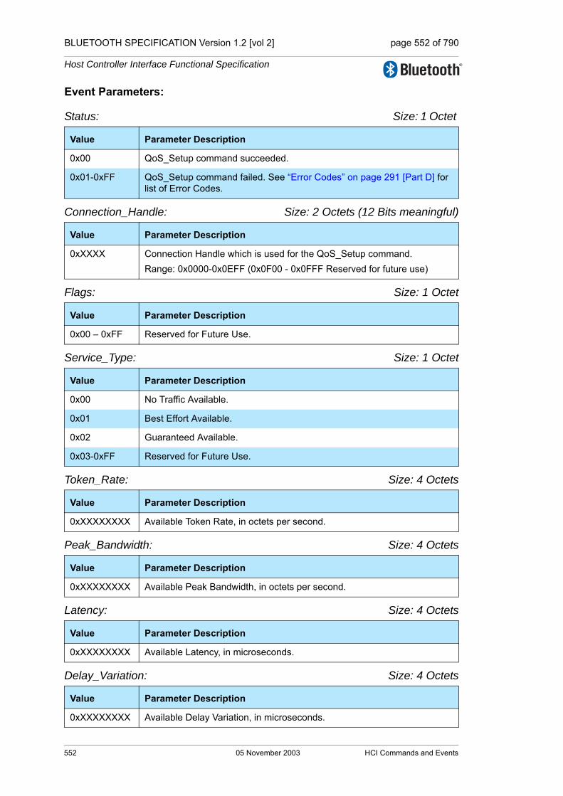
BLUETOOTH SPECIFICATION Version 1.2 [vol 2] page 552 of 790
Host Controller Interface Functional Specification
Event Parameters:
Status: Size: 1 Octet
Connection_Handle: Size: 2 Octets (12 Bits meaningful)
Flags: Size: 1 Octet
Service_Type: Size: 1 Octet
Token_Rate: Size: 4 Octets
Peak_Bandwidth: Size: 4 Octets
Latency: Size: 4 Octets
Delay_Variation: Size: 4 Octets
Value Parameter Description
0x00 QoS_Setup command succeeded.
0x01-0xFF QoS_Setup command failed. See “Error Codes” on page 291 [Part D] for list of Error Codes.
Value Parameter Description
0xXXXX Connection Handle which is used for the QoS_Setup command. Range: 0x0000-0x0EFF (0x0F00 - 0x0FFF Reserved for future use)
Value Parameter Description
0x00 – 0xFF Reserved for Future Use.
Value Parameter Description
0x00 No Traffic Available.
0x01 Best Effort Available.
0x02 Guaranteed Available.
0x03-0xFF Reserved for Future Use.
Value Parameter Description
0xXXXXXXXX Available Token Rate, in octets per second.
Value Parameter Description
0xXXXXXXXX Available Peak Bandwidth, in octets per second.
Value Parameter Description
0xXXXXXXXX Available Latency, in microseconds.
Value Parameter Description
0xXXXXXXXX Available Delay Variation, in microseconds.
552 05 November 2003 HCI Commands and Events
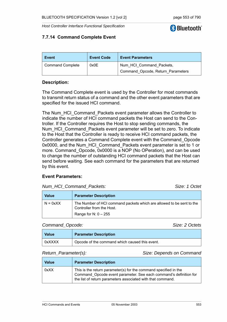
BLUETOOTH SPECIFICATION Version 1.2 [vol 2] page 553 of 790
Host Controller Interface Functional Specification
7.7.14 Command Complete Event
Description:
The Command Complete event is used by the Controller for most commands to transmit return status of a command and the other event parameters that are specified for the issued HCI command.
The Num_HCI_Command_Packets event parameter allows the Controller to indicate the number of HCI command packets the Host can send to the Con-troller. If the Controller requires the Host to stop sending commands, the Num_HCI_Command_Packets event parameter will be set to zero. To indicate to the Host that the Controller is ready to receive HCI command packets, the Controller generates a Command Complete event with the Command_Opcode 0x0000, and the Num_HCI_Command_Packets event parameter is set to 1 or more. Command_Opcode, 0x0000 is a NOP (No OPeration), and can be used to change the number of outstanding HCI command packets that the Host can send before waiting. See each command for the parameters that are returned by this event.
Event Parameters:
Num_HCI_Command_Packets: Size: 1 Octet
Command_Opcode: Size: 2 Octets
Return_Parameter(s): Size: Depends on Command
Event Event Code Event Parameters
Command Complete 0x0E Num_HCI_Command_Packets,Command_Opcode, Return_Parameters
Value Parameter Description
N = 0xXX The Number of HCI command packets which are allowed to be sent to the Controller from the Host.Range for N: 0 – 255
Value Parameter Description
0xXXXX Opcode of the command which caused this event.
Value Parameter Description
0xXX This is the return parameter(s) for the command specified in the Command_Opcode event parameter. See each command’s definition for the list of return parameters associated with that command.
HCI Commands and Events 05 November 2003 553

BLUETOOTH SPECIFICATION Version 1.2 [vol 2] page 554 of 790
Host Controller Interface Functional Specification
7.7.15 Command Status Event
Description:
The Command Status event is used to indicate that the command described by the Command_Opcode parameter has been received, and that the Controller is currently performing the task for this command. This event is needed to pro-vide mechanisms for asynchronous operation, which makes it possible to pre-vent the Host from waiting for a command to finish. If the command can not begin to execute (a parameter error may have occurred, or the command may currently not be allowed), the Status event parameter will contain the corre-sponding error code, and no complete event will follow since the command was not started. The Num_HCI_Command_Packets event parameter allows the Controller to indicate the number of HCI command packets the Host can send to the Controller. If the Controller requires the Host to stop sending commands, the Num_HCI_Command_Packets event parameter will be set to zero. To indi-cate to the Host that the Controller is ready to receive HCI command packets, the Controller generates a Command Status event with Status 0x00 and Command_Opcode 0x0000, and the Num_HCI_Command_Packets event parameter is set to 1 or more. Command_Opcode, 0x0000 is a NOP (No OPer-ation) and can be used to change the number of outstanding HCI command packets that the Host can send before waiting.
Event Parameters:Status: Size: 1 Octet
Num_HCI_Command_Packets: Size: 1 Octet
Command_Opcode: Size: 2 Octets
Event Event Code Event Parameters
Command Status 0x0F Status,Num_HCI_Command_Packets,Command_Opcode
Value Parameter Description
0x00 Command currently in pending.
0x01-0xFF Command failed. See “Error Codes” on page 291 [Part D] for list of Error Codes.
Value Parameter Description
N = 0xXX The Number of HCI command packets which are allowed to be sent to the Controller from the Host. Range for N: 0 – 255
Value Parameter Description
0xXXXX Opcode of the command which caused this event and is pending completion.
554 05 November 2003 HCI Commands and Events
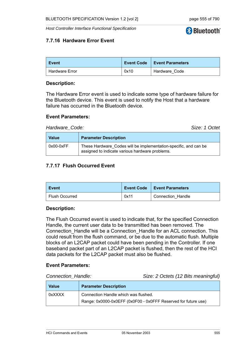
BLUETOOTH SPECIFICATION Version 1.2 [vol 2] page 555 of 790
Host Controller Interface Functional Specification
7.7.16 Hardware Error Event
Description:
The Hardware Error event is used to indicate some type of hardware failure for the Bluetooth device. This event is used to notify the Host that a hardware failure has occurred in the Bluetooth device.
Event Parameters:
Hardware_Code: Size: 1 Octet
7.7.17 Flush Occurred Event
Description:
The Flush Occurred event is used to indicate that, for the specified Connection Handle, the current user data to be transmitted has been removed. The Connection_Handle will be a Connection_Handle for an ACL connection. This could result from the flush command, or be due to the automatic flush. Multiple blocks of an L2CAP packet could have been pending in the Controller. If one baseband packet part of an L2CAP packet is flushed, then the rest of the HCI data packets for the L2CAP packet must also be flushed.
Event Parameters:
Connection_Handle: Size: 2 Octets (12 Bits meaningful)
Event Event Code Event Parameters
Hardware Error 0x10 Hardware_Code
Value Parameter Description
0x00-0xFF These Hardware_Codes will be implementation-specific, and can be assigned to indicate various hardware problems.
Event Event Code Event Parameters
Flush Occurred 0x11 Connection_Handle
Value Parameter Description
0xXXXX Connection Handle which was flushed.Range: 0x0000-0x0EFF (0x0F00 - 0x0FFF Reserved for future use)
HCI Commands and Events 05 November 2003 555

BLUETOOTH SPECIFICATION Version 1.2 [vol 2] page 556 of 790
Host Controller Interface Functional Specification
7.7.18 Role Change Event
Description:
The Role Change event is used to indicate that the current Bluetooth role related to the particular connection has changed. This event only occurs when both the remote and local Bluetooth devices have completed their role change for the Bluetooth device associated with the BD_ADDR event parameter. This event allows both affected Hosts to be notified when the Role has been changed.
Event Parameters:
Status: Size: 1 Octet
BD_ADDR: Size: 6 Octets
New_Role: Size: 1 Octet
Event Event Code Event Parameters
Role Change 0x12 Status,BD_ADDR, New_Role
Value Parameter Description
0x00 Role change has occurred.
0x01-0xFF Role change failed. See “Error Codes” on page 291 [Part D] for list of Error Codes.
Value Parameter Description
0xXXXXXXXXXXXX BD_ADDR of the Device for which a role change has completed.
Value Parameter Description
0x00 Currently the Master for specified BD_ADDR.
0x01 Currently the Slave for specified BD_ADDR.
556 05 November 2003 HCI Commands and Events

BLUETOOTH SPECIFICATION Version 1.2 [vol 2] page 557 of 790
Host Controller Interface Functional Specification
7.7.19 Number Of Completed Packets Event
Description:
The Number Of Completed Packets event is used by the Controller to indicate to the Host how many HCI Data Packets have been completed (transmitted or flushed) for each Connection Handle since the previous Number Of Completed Packets event was sent to the Host. This means that the corresponding buffer space has been freed in the Controller. Based on this information, and the HC_Total_Num_ACL_Data_Packets and HC_Total_Num_Synchronous_Data_Packets return parameter of the Read_Buffer_Size command, the Host can determine for which Connection Handles the following HCI Data Packets should be sent to the Controller.The Number Of Completed Packets event must not be sent before the corresponding Connec-tion Complete event. While the Controller has HCI data packets in its buffer, it must keep sending the Number Of Completed Packets event to the Host at least periodically, until it finally reports that all the pending ACL Data Packets have been transmitted or flushed. The rate with which this event is sent is man-ufacturer specific.Note that Number Of Completed Packets events will not report on synchronous connection handles if synchronous Flow Control is disabled. (See Read/Write_Synchronous_Flow_Control_Enable on page 486 and page 487.)
Event Parameters:
Number_of_Handles: Size: 1 Octet
Connection_Handle[i]: Size: Number_of_Handles * 2 Octets(12 Bits meaning-ful)
Event Event Code Event Parameters
Number Of Completed Packets 0x13 Number_of_Handles, Connection_Handle[i],HC_Num_Of_Completed_Packets[i]
Value Parameter Description
0xXX The number of Connection Handles and Num_HCI_Data_Packets parameters pairs contained in this event.Range: 0-255
Value Parameter Description
0xXXXX Connection Handle. Range: 0x0000-0x0EFF (0x0F00 - 0x0FFF Reserved for future use)
HCI Commands and Events 05 November 2003 557
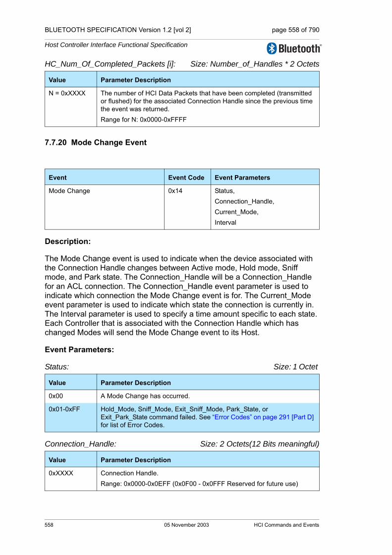
BLUETOOTH SPECIFICATION Version 1.2 [vol 2] page 558 of 790
Host Controller Interface Functional Specification
HC_Num_Of_Completed_Packets [i]: Size: Number_of_Handles * 2 Octets
7.7.20 Mode Change Event
Description:
The Mode Change event is used to indicate when the device associated with the Connection Handle changes between Active mode, Hold mode, Sniff mode, and Park state. The Connection_Handle will be a Connection_Handle for an ACL connection. The Connection_Handle event parameter is used to indicate which connection the Mode Change event is for. The Current_Mode event parameter is used to indicate which state the connection is currently in. The Interval parameter is used to specify a time amount specific to each state. Each Controller that is associated with the Connection Handle which has changed Modes will send the Mode Change event to its Host.
Event Parameters:
Status: Size: 1 Octet
Connection_Handle: Size: 2 Octets(12 Bits meaningful)
Value Parameter Description
N = 0xXXXX The number of HCI Data Packets that have been completed (transmitted or flushed) for the associated Connection Handle since the previous time the event was returned.Range for N: 0x0000-0xFFFF
Event Event Code Event Parameters
Mode Change 0x14 Status, Connection_Handle,Current_Mode, Interval
Value Parameter Description
0x00 A Mode Change has occurred.
0x01-0xFF Hold_Mode, Sniff_Mode, Exit_Sniff_Mode, Park_State, or Exit_Park_State command failed. See “Error Codes” on page 291 [Part D] for list of Error Codes.
Value Parameter Description
0xXXXX Connection Handle. Range: 0x0000-0x0EFF (0x0F00 - 0x0FFF Reserved for future use)
558 05 November 2003 HCI Commands and Events
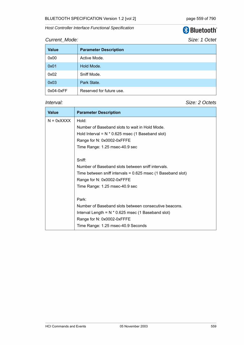
BLUETOOTH SPECIFICATION Version 1.2 [vol 2] page 559 of 790
Host Controller Interface Functional Specification
Current_Mode: Size: 1 Octet
Interval: Size: 2 Octets
Value Parameter Description
0x00 Active Mode.
0x01 Hold Mode.
0x02 Sniff Mode.
0x03 Park State.
0x04-0xFF Reserved for future use.
Value Parameter Description
N = 0xXXXX Hold:Number of Baseband slots to wait in Hold Mode.Hold Interval = N * 0.625 msec (1 Baseband slot)Range for N: 0x0002-0xFFFETime Range: 1.25 msec-40.9 sec
Sniff:Number of Baseband slots between sniff intervals.Time between sniff intervals = 0.625 msec (1 Baseband slot)Range for N: 0x0002-0xFFFETime Range: 1.25 msec-40.9 sec
Park:Number of Baseband slots between consecutive beacons.Interval Length = N * 0.625 msec (1 Baseband slot)Range for N: 0x0002-0xFFFETime Range: 1.25 msec-40.9 Seconds
HCI Commands and Events 05 November 2003 559
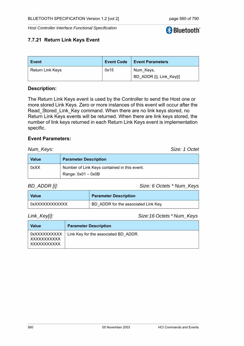
BLUETOOTH SPECIFICATION Version 1.2 [vol 2] page 560 of 790
Host Controller Interface Functional Specification
7.7.21 Return Link Keys Event
Description:
The Return Link Keys event is used by the Controller to send the Host one or more stored Link Keys. Zero or more instances of this event will occur after the Read_Stored_Link_Key command. When there are no link keys stored, no Return Link Keys events will be returned. When there are link keys stored, the number of link keys returned in each Return Link Keys event is implementation specific.
Event Parameters:
Num_Keys: Size: 1 Octet
BD_ADDR [i]: Size: 6 Octets * Num_Keys
Link_Key[i]: Size:16 Octets * Num_Keys
Event Event Code Event Parameters
Return Link Keys 0x15 Num_Keys,BD_ADDR [i], Link_Key[i]
Value Parameter Description
0xXX Number of Link Keys contained in this event.Range: 0x01 – 0x0B
Value Parameter Description
0xXXXXXXXXXXXX BD_ADDR for the associated Link Key.
Value Parameter Description
0xXXXXXXXXXXXXXXXXXXXXXXXXXXXXXXXX
Link Key for the associated BD_ADDR.
560 05 November 2003 HCI Commands and Events
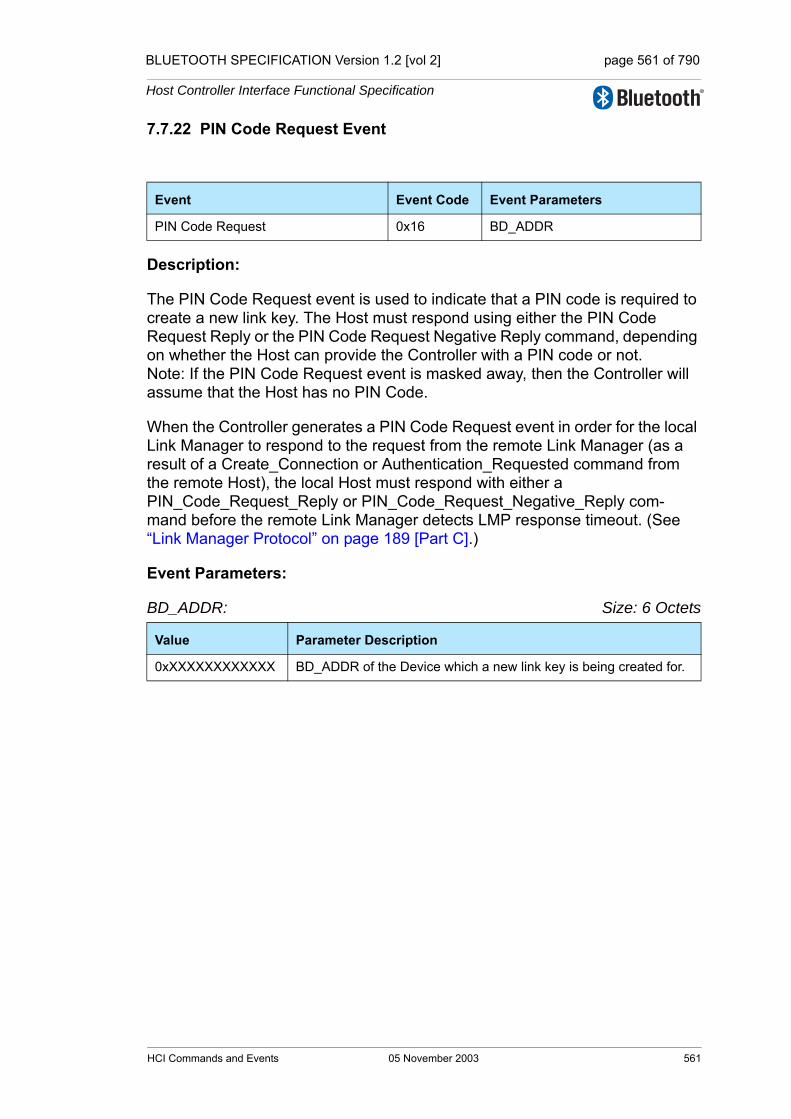
BLUETOOTH SPECIFICATION Version 1.2 [vol 2] page 561 of 790
Host Controller Interface Functional Specification
7.7.22 PIN Code Request Event
Description:
The PIN Code Request event is used to indicate that a PIN code is required to create a new link key. The Host must respond using either the PIN Code Request Reply or the PIN Code Request Negative Reply command, depending on whether the Host can provide the Controller with a PIN code or not.Note: If the PIN Code Request event is masked away, then the Controller will assume that the Host has no PIN Code.
When the Controller generates a PIN Code Request event in order for the local Link Manager to respond to the request from the remote Link Manager (as a result of a Create_Connection or Authentication_Requested command from the remote Host), the local Host must respond with either a PIN_Code_Request_Reply or PIN_Code_Request_Negative_Reply com-mand before the remote Link Manager detects LMP response timeout. (See “Link Manager Protocol” on page 189 [Part C].)
Event Parameters:
BD_ADDR: Size: 6 Octets
Event Event Code Event Parameters
PIN Code Request 0x16 BD_ADDR
Value Parameter Description
0xXXXXXXXXXXXX BD_ADDR of the Device which a new link key is being created for.
HCI Commands and Events 05 November 2003 561
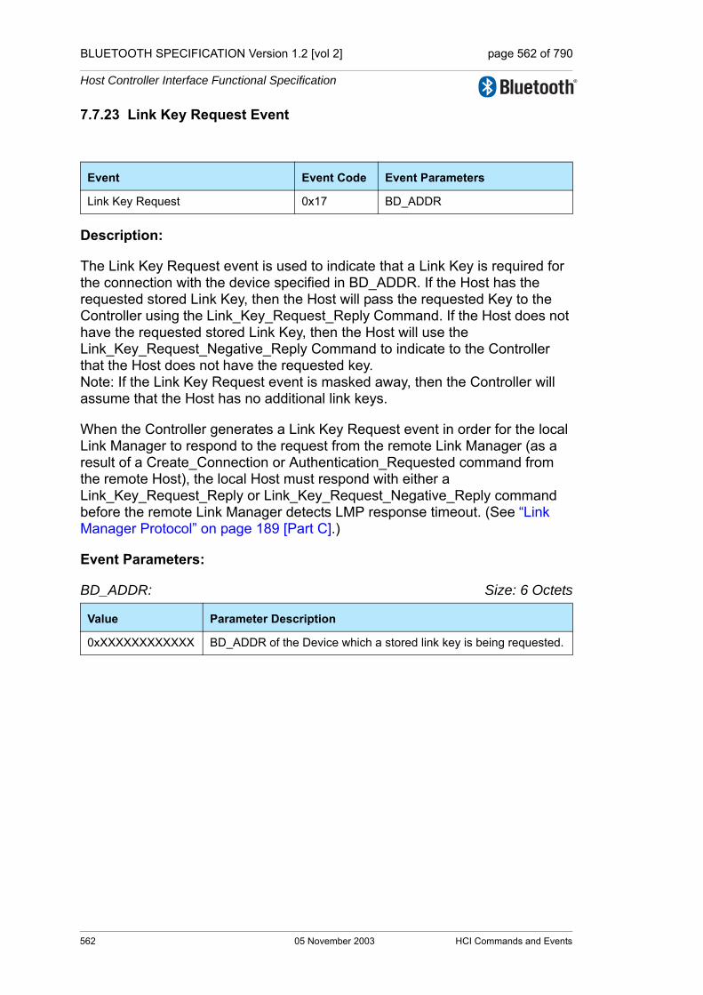
BLUETOOTH SPECIFICATION Version 1.2 [vol 2] page 562 of 790
Host Controller Interface Functional Specification
7.7.23 Link Key Request Event
Description:
The Link Key Request event is used to indicate that a Link Key is required for the connection with the device specified in BD_ADDR. If the Host has the requested stored Link Key, then the Host will pass the requested Key to the Controller using the Link_Key_Request_Reply Command. If the Host does not have the requested stored Link Key, then the Host will use the Link_Key_Request_Negative_Reply Command to indicate to the Controller that the Host does not have the requested key. Note: If the Link Key Request event is masked away, then the Controller will assume that the Host has no additional link keys.
When the Controller generates a Link Key Request event in order for the local Link Manager to respond to the request from the remote Link Manager (as a result of a Create_Connection or Authentication_Requested command from the remote Host), the local Host must respond with either a Link_Key_Request_Reply or Link_Key_Request_Negative_Reply command before the remote Link Manager detects LMP response timeout. (See “Link Manager Protocol” on page 189 [Part C].)
Event Parameters:
BD_ADDR: Size: 6 Octets
Event Event Code Event Parameters
Link Key Request 0x17 BD_ADDR
Value Parameter Description
0xXXXXXXXXXXXX BD_ADDR of the Device which a stored link key is being requested.
562 05 November 2003 HCI Commands and Events
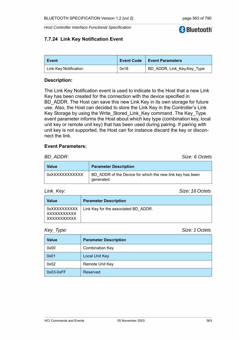
BLUETOOTH SPECIFICATION Version 1.2 [vol 2] page 563 of 790
Host Controller Interface Functional Specification
7.7.24 Link Key Notification Event
Description:
The Link Key Notification event is used to indicate to the Host that a new Link Key has been created for the connection with the device specified in BD_ADDR. The Host can save this new Link Key in its own storage for future use. Also, the Host can decided to store the Link Key in the Controller’s Link Key Storage by using the Write_Stored_Link_Key command. The Key_Type event parameter informs the Host about which key type (combination key, local unit key or remote unit key) that has been used during pairing. If pairing with unit key is not supported, the Host can for instance discard the key or discon-nect the link.
Event Parameters:
BD_ADDR: Size: 6 Octets
Link_Key: Size: 16 Octets
Key_Type: Size: 1 Octets
Event Event Code Event Parameters
Link Key Notification 0x18 BD_ADDR, Link_Key,Key_Type
Value Parameter Description
0xXXXXXXXXXXXX BD_ADDR of the Device for which the new link key has been generated.
Value Parameter Description
0xXXXXXXXXXXXXXXXXXXXXXXXXXXXXXXXX
Link Key for the associated BD_ADDR.
Value Parameter Description
0x00 Combination Key
0x01 Local Unit Key
0x02 Remote Unit Key
0x03-0xFF Reserved
HCI Commands and Events 05 November 2003 563

BLUETOOTH SPECIFICATION Version 1.2 [vol 2] page 564 of 790
Host Controller Interface Functional Specification
7.7.25 Loopback Command Event
Description: When in Local Loopback mode, the Controller loops back commands and data to the Host. The Loopback Command event is used to loop back all commands that the Host sends to the Controller with some exceptions. See Section 7.6.1, “Read Loopback Mode Command,” on page 531 for a description of which commands that are not looped back. The HCI_Command_Packet event parameter contains the entire HCI Command Packet including the header. Note: the event packet is limited to a maximum of 255 octets in the payload; since an HCI Command Packet has 3 octets of header data, only the first 252 octets of the command parameters will be returned.
Event Parameters:
HCI_Command_Packet: Size: Depends on Command
7.7.26 Data Buffer Overflow Event
Description:
This event is used to indicate that the Controller’s data buffers have been over-flowed. This can occur if the Host has sent more packets than allowed. The Link_Type parameter is used to indicate that the overflow was caused by ACL or synchronous data.
Event Parameters:
Link_Type: Size: 1 Octet
Event Event Code Event Parameters
Loopback Command 0x19 HCI_Command_Packet
Value Parameter Description
0xXXXXXX HCI Command Packet, including header.
Event Event Code Event Parameters
Data Buffer Overflow 0x1A Link_Type
Value Parameter Description
0x00 Synchronous Buffer Overflow (Voice Channels).
0x01 ACL Buffer Overflow (Data Channels).
0x02-0xFF Reserved for Future Use.
564 05 November 2003 HCI Commands and Events
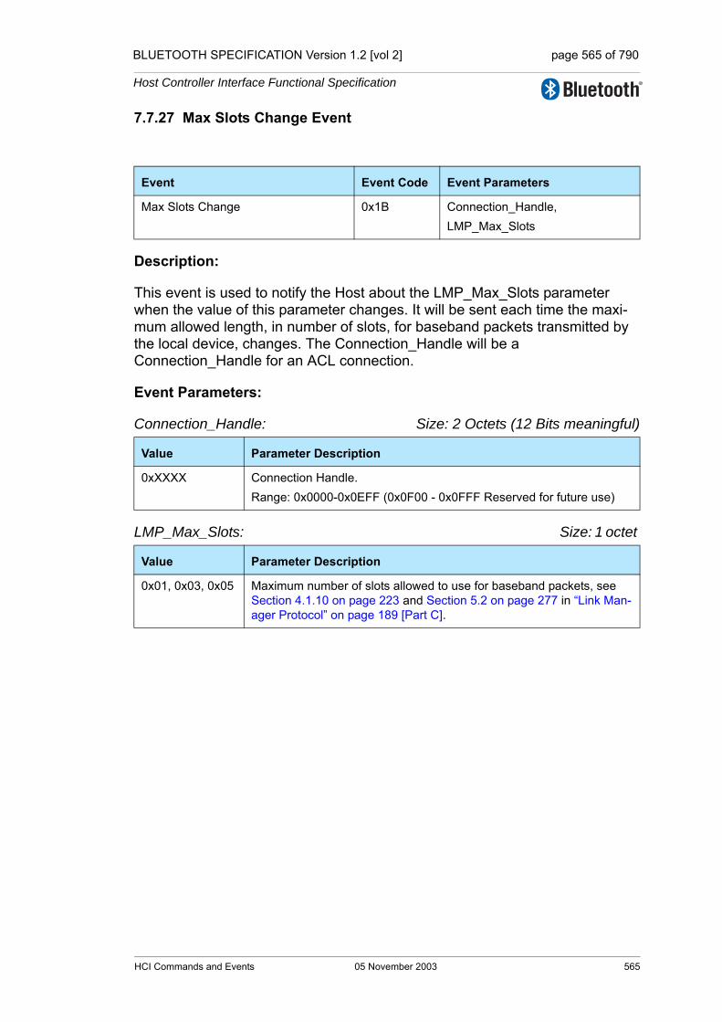
BLUETOOTH SPECIFICATION Version 1.2 [vol 2] page 565 of 790
Host Controller Interface Functional Specification
7.7.27 Max Slots Change Event
Description:
This event is used to notify the Host about the LMP_Max_Slots parameter when the value of this parameter changes. It will be sent each time the maxi-mum allowed length, in number of slots, for baseband packets transmitted by the local device, changes. The Connection_Handle will be a Connection_Handle for an ACL connection.
Event Parameters:
Connection_Handle: Size: 2 Octets (12 Bits meaningful)
LMP_Max_Slots: Size: 1 octet
Event Event Code Event Parameters
Max Slots Change 0x1B Connection_Handle,LMP_Max_Slots
Value Parameter Description
0xXXXX Connection Handle. Range: 0x0000-0x0EFF (0x0F00 - 0x0FFF Reserved for future use)
Value Parameter Description
0x01, 0x03, 0x05 Maximum number of slots allowed to use for baseband packets, see Section 4.1.10 on page 223 and Section 5.2 on page 277 in “Link Man-ager Protocol” on page 189 [Part C].
HCI Commands and Events 05 November 2003 565

BLUETOOTH SPECIFICATION Version 1.2 [vol 2] page 566 of 790
Host Controller Interface Functional Specification
7.7.28 Read Clock Offset Complete Event
Description:
The Read Clock Offset Complete event is used to indicate the completion of the process of the Link Manager obtaining the Clock Offset information of the Bluetooth device specified by the Connection_Handle event parameter. The Connection_Handle will be a Connection_Handle for an ACL connection.
Event Parameters:
Status: Size: 1 Octet
Connection_Handle: Size: 2 Octets (12 bits meaningful)
Clock_Offset: Size: 2 Octets
Event Event Code Event Parameters
Read Clock Offset Complete 0x1C Status,Connection_Handle, Clock_Offset
Value Parameter Description
0x00 Read_Clock_Offset command succeeded.
0x01-0xFF Read_Clock_Offset command failed. See “Error Codes” on page 291 [Part D] for list of Error Codes.
Value Parameter Description
0xXXXX Specifies which Connection Handle’s Clock Offset parameter is returned.Range: 0x0000-0x0EFF (0x0F00 - 0x0FFF Reserved for future use)
Bit format Parameter Description
Bit 14-0 Bit 16-2 of CLKslave-CLKmaster.
Bit 15 Reserved.
566 05 November 2003 HCI Commands and Events
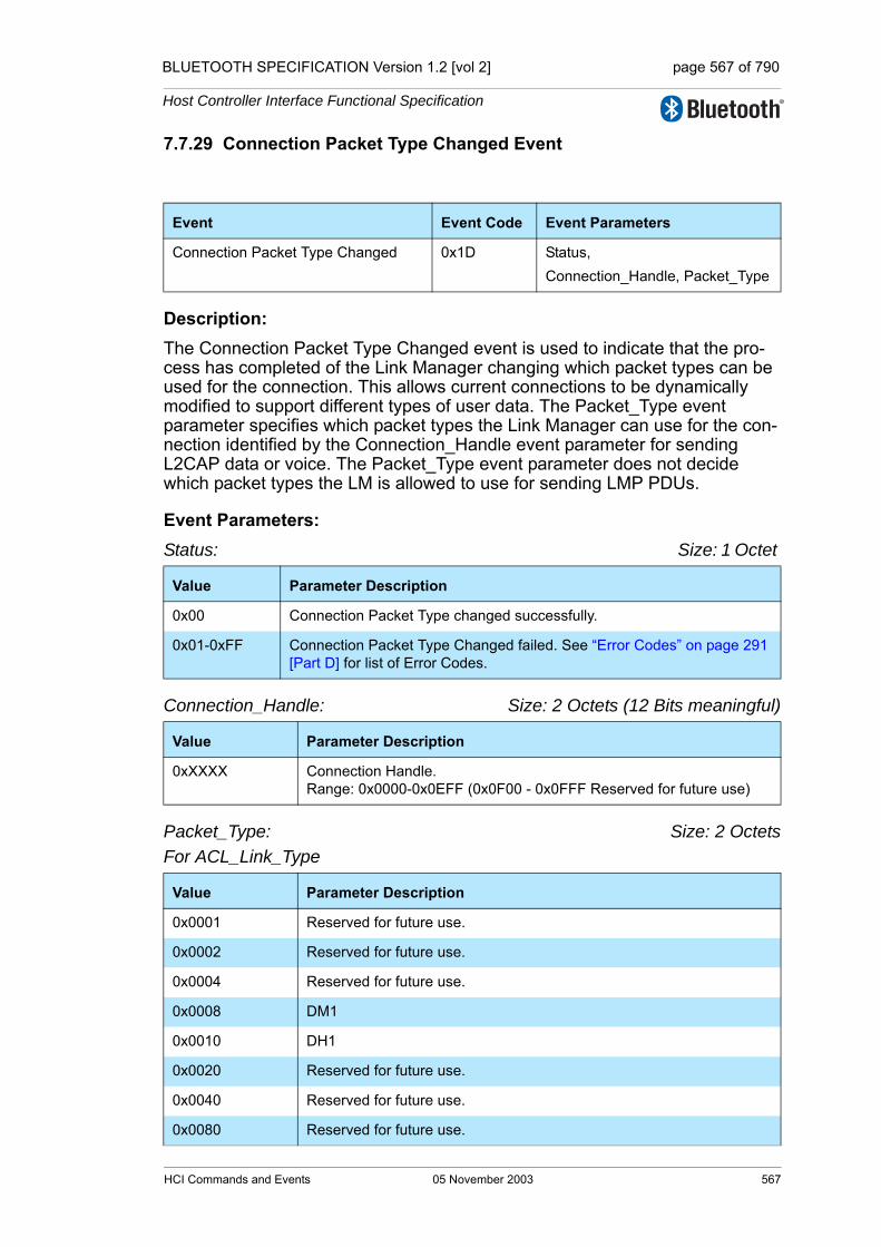
BLUETOOTH SPECIFICATION Version 1.2 [vol 2] page 567 of 790
Host Controller Interface Functional Specification
7.7.29 Connection Packet Type Changed Event
Description: The Connection Packet Type Changed event is used to indicate that the pro-cess has completed of the Link Manager changing which packet types can be used for the connection. This allows current connections to be dynamically modified to support different types of user data. The Packet_Type event parameter specifies which packet types the Link Manager can use for the con-nection identified by the Connection_Handle event parameter for sending L2CAP data or voice. The Packet_Type event parameter does not decide which packet types the LM is allowed to use for sending LMP PDUs.
Event Parameters:Status: Size: 1 Octet
Connection_Handle: Size: 2 Octets (12 Bits meaningful)
Packet_Type: Size: 2 OctetsFor ACL_Link_Type
Event Event Code Event Parameters
Connection Packet Type Changed 0x1D Status,Connection_Handle, Packet_Type
Value Parameter Description
0x00 Connection Packet Type changed successfully.
0x01-0xFF Connection Packet Type Changed failed. See “Error Codes” on page 291 [Part D] for list of Error Codes.
Value Parameter Description
0xXXXX Connection Handle. Range: 0x0000-0x0EFF (0x0F00 - 0x0FFF Reserved for future use)
Value Parameter Description
0x0001 Reserved for future use.
0x0002 Reserved for future use.
0x0004 Reserved for future use.
0x0008 DM1
0x0010 DH1
0x0020 Reserved for future use.
0x0040 Reserved for future use.
0x0080 Reserved for future use.
HCI Commands and Events 05 November 2003 567

BLUETOOTH SPECIFICATION Version 1.2 [vol 2] page 568 of 790
Host Controller Interface Functional Specification
For SCO_Link_Type
Value Parameter Description
0x0100 Reserved for future use.
0x0200 Reserved for future use.
0x0400 DM3
0x0800 DH3
0x1000 Reserved for future use.
0x2000 Reserved for future use.
0x4000 DM5
0x8000 DH5
Value Parameter Description
0x0001 Reserved for future use.
0x0002 Reserved for future use.
0x0004 Reserved for future use.
0x0008 Reserved for future use.
0x0010 Reserved for future use.
0x0020 HV1
0x0040 HV2
0x0080 HV3
0x0100 Reserved for future use.
0x0200 Reserved for future use.
0x0400 Reserved for future use.
0x0800 Reserved for future use.
0x1000 Reserved for future use.
0x2000 Reserved for future use.
0x4000 Reserved for future use.
0x8000 Reserved for future use.
568 05 November 2003 HCI Commands and Events

BLUETOOTH SPECIFICATION Version 1.2 [vol 2] page 569 of 790
Host Controller Interface Functional Specification
7.7.30 QoS Violation Event
Description:
The QoS Violation event is used to indicate the Link Manager is unable to pro-vide the current QoS requirement for the Connection Handle. This event indi-cates that the Link Manager is unable to provide one or more of the agreed QoS parameters. The Host chooses what action should be done. The Host can reissue QoS_Setup command to renegotiate the QoS setting for Connection Handle. The Connection_Handle will be a Connection_Handle for an ACL con-nection.
Event Parameters:
Connection_Handle: Size: 2 Octets (12 Bits meaningful)
Event Event Code Event Parameters
QoS Violation 0x1E Connection_Handle
Value Parameter Description
0xXXXX Connection Handle that the LM is unable to provide the current QoS requested for.Range: 0x0000-0x0EFF (0x0F00 - 0x0FFF Reserved for future use)
HCI Commands and Events 05 November 2003 569
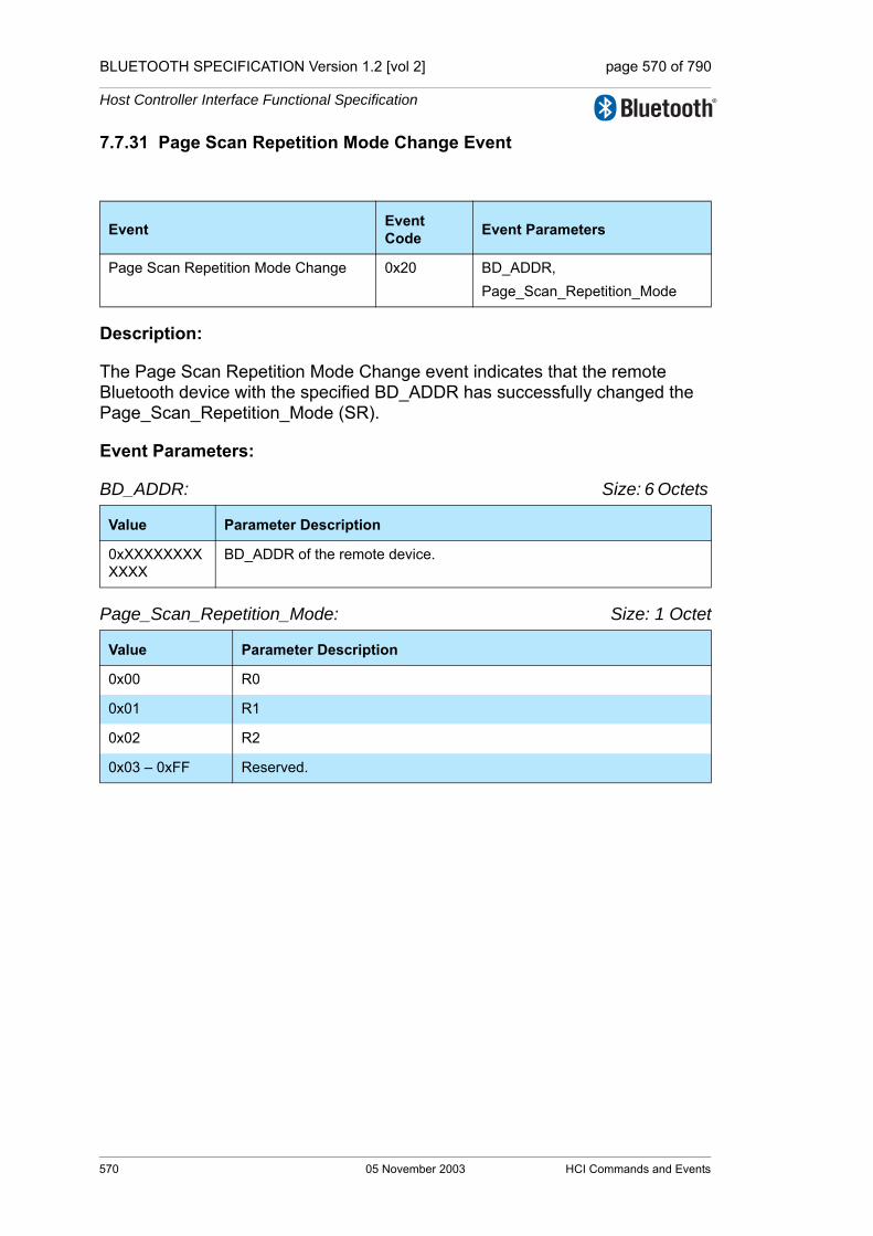
BLUETOOTH SPECIFICATION Version 1.2 [vol 2] page 570 of 790
Host Controller Interface Functional Specification
7.7.31 Page Scan Repetition Mode Change Event
Description:
The Page Scan Repetition Mode Change event indicates that the remote Bluetooth device with the specified BD_ADDR has successfully changed the Page_Scan_Repetition_Mode (SR).
Event Parameters:
BD_ADDR: Size: 6 Octets
Page_Scan_Repetition_Mode: Size: 1 Octet
Event Event Code Event Parameters
Page Scan Repetition Mode Change 0x20 BD_ADDR,Page_Scan_Repetition_Mode
Value Parameter Description
0xXXXXXXXXXXXX
BD_ADDR of the remote device.
Value Parameter Description
0x00 R0
0x01 R1
0x02 R2
0x03 – 0xFF Reserved.
570 05 November 2003 HCI Commands and Events
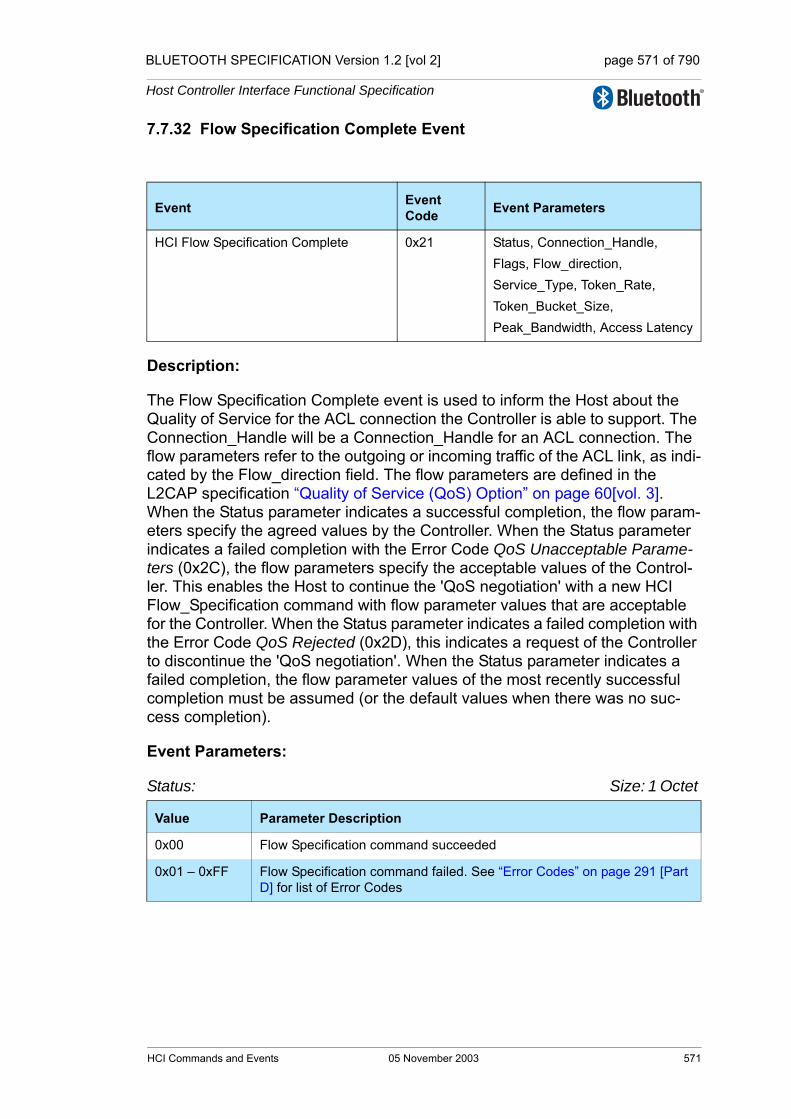
BLUETOOTH SPECIFICATION Version 1.2 [vol 2] page 571 of 790
Host Controller Interface Functional Specification
7.7.32 Flow Specification Complete Event
Description:
The Flow Specification Complete event is used to inform the Host about the Quality of Service for the ACL connection the Controller is able to support. The Connection_Handle will be a Connection_Handle for an ACL connection. The flow parameters refer to the outgoing or incoming traffic of the ACL link, as indi-cated by the Flow_direction field. The flow parameters are defined in the L2CAP specification “Quality of Service (QoS) Option” on page 60[vol. 3]. When the Status parameter indicates a successful completion, the flow param-eters specify the agreed values by the Controller. When the Status parameter indicates a failed completion with the Error Code QoS Unacceptable Parame-ters (0x2C), the flow parameters specify the acceptable values of the Control-ler. This enables the Host to continue the 'QoS negotiation' with a new HCI Flow_Specification command with flow parameter values that are acceptable for the Controller. When the Status parameter indicates a failed completion with the Error Code QoS Rejected (0x2D), this indicates a request of the Controller to discontinue the 'QoS negotiation'. When the Status parameter indicates a failed completion, the flow parameter values of the most recently successful completion must be assumed (or the default values when there was no suc-cess completion).
Event Parameters:
Status: Size: 1 Octet
Event Event Code Event Parameters
HCI Flow Specification Complete 0x21 Status, Connection_Handle,Flags, Flow_direction,Service_Type, Token_Rate,Token_Bucket_Size,Peak_Bandwidth, Access Latency
Value Parameter Description
0x00 Flow Specification command succeeded
0x01 – 0xFF Flow Specification command failed. See “Error Codes” on page 291 [Part D] for list of Error Codes
HCI Commands and Events 05 November 2003 571
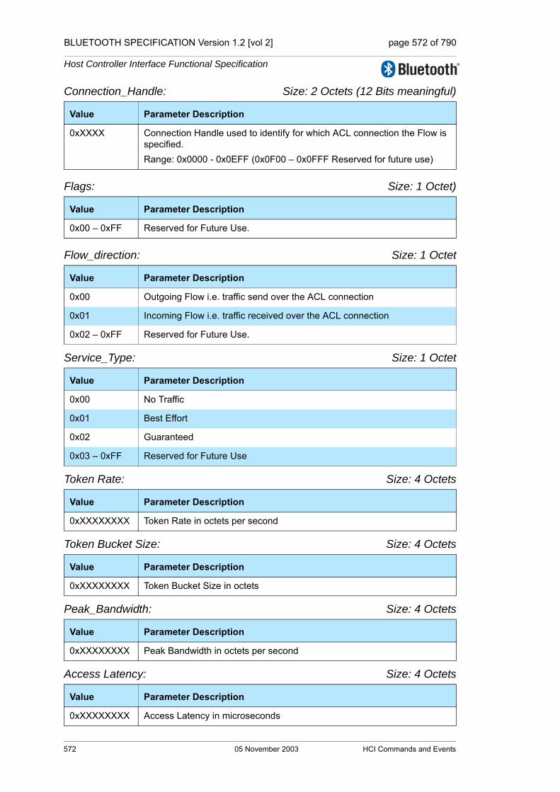
BLUETOOTH SPECIFICATION Version 1.2 [vol 2] page 572 of 790
Host Controller Interface Functional Specification
Connection_Handle: Size: 2 Octets (12 Bits meaningful)
Flags: Size: 1 Octet)
Flow_direction: Size: 1 Octet
Service_Type: Size: 1 Octet
Token Rate: Size: 4 Octets
Token Bucket Size: Size: 4 Octets
Peak_Bandwidth: Size: 4 Octets
Access Latency: Size: 4 Octets
Value Parameter Description
0xXXXX Connection Handle used to identify for which ACL connection the Flow is specified. Range: 0x0000 - 0x0EFF (0x0F00 – 0x0FFF Reserved for future use)
Value Parameter Description
0x00 – 0xFF Reserved for Future Use.
Value Parameter Description
0x00 Outgoing Flow i.e. traffic send over the ACL connection
0x01 Incoming Flow i.e. traffic received over the ACL connection
0x02 – 0xFF Reserved for Future Use.
Value Parameter Description
0x00 No Traffic
0x01 Best Effort
0x02 Guaranteed
0x03 – 0xFF Reserved for Future Use
Value Parameter Description
0xXXXXXXXX Token Rate in octets per second
Value Parameter Description
0xXXXXXXXX Token Bucket Size in octets
Value Parameter Description
0xXXXXXXXX Peak Bandwidth in octets per second
Value Parameter Description
0xXXXXXXXX Access Latency in microseconds
572 05 November 2003 HCI Commands and Events

BLUETOOTH SPECIFICATION Version 1.2 [vol 2] page 573 of 790
Host Controller Interface Functional Specification
7.7.33 Inquiry Result with RSSI Event
Description: The Inquiry Result with RSSI event indicates that a Bluetooth device or multiple Bluetooth devices have responded so far during the current Inquiry process. This event will be sent from the Controller to the Host as soon as an Inquiry Response from a remote device is received if the remote device supports only mandatory paging scheme. This Controller may queue these Inquiry Responses and send multiple Bluetooth devices information in one Inquiry Result event. The event can be used to return one or more Inquiry responses in one event. The RSSI parameter is measured during the FHS packet returned by each responding slave.
This event shall only be generated if the Inquiry Mode parameter of the last Write_Inquiry_Mode command was set to 0x01 (Inquiry Result format with RSSI).
Note: the only difference between the Inquiry Result with RSSI event and the Inquiry Result event is the additional RSSI parameter.
Event Parameters:
Num_Responses: Size: 1 Octet
BD_ADDR[i]: Size: 6 Octets * Num_Responses
Event Event Code Event Parameters
Inquiry Result with RSSI 0x22 Num_responses,BD_ADDR[i],Page_Scan_Repetition_Mode[i],Page_Scan_Period_Mode[i],Class_of_Device[i],Clock_Offset[i],RSSI[i]
Value Parameter Description
0xXX Number of responses from the Inquiry.
Value Parameter Description
0xXXXXXXXXXXXX
BD_ADDR for each device which responded.
HCI Commands and Events 05 November 2003 573

BLUETOOTH SPECIFICATION Version 1.2 [vol 2] page 574 of 790
Host Controller Interface Functional Specification
Page_Scan_Repetition_Mode[i]: Size: 1 Octet* Num_Responses
Page_Scan_Period_Mode[i]: Size: 1 Octet* Num_Responses
Class_of_Device[i]: Size: 3 Octets * Num_Responses
Clock_Offset[i]: Size: 2 Octets * Num_Responses
RSSI[i]: Size: 1 Octet * Num_Responses
Value Parameter Description
0x00 R0
0x01 R1
0x02 R2
0x03 – 0xFF Reserved
Value Parameter Description
0x00 P0
0x01 P1
0x02 P2
0x03 – 0xFF Reserved
Value Parameter Description
0xXXXXXX Class of Device for the device
Bit format Parameter Description
Bit 14-0 Bit 16-2 of CLKslave-CLKmaster.
Bit 15 Reserved
Value Parameter Description
0xXX Range: -127 to +20Units: dBm
574 05 November 2003 HCI Commands and Events
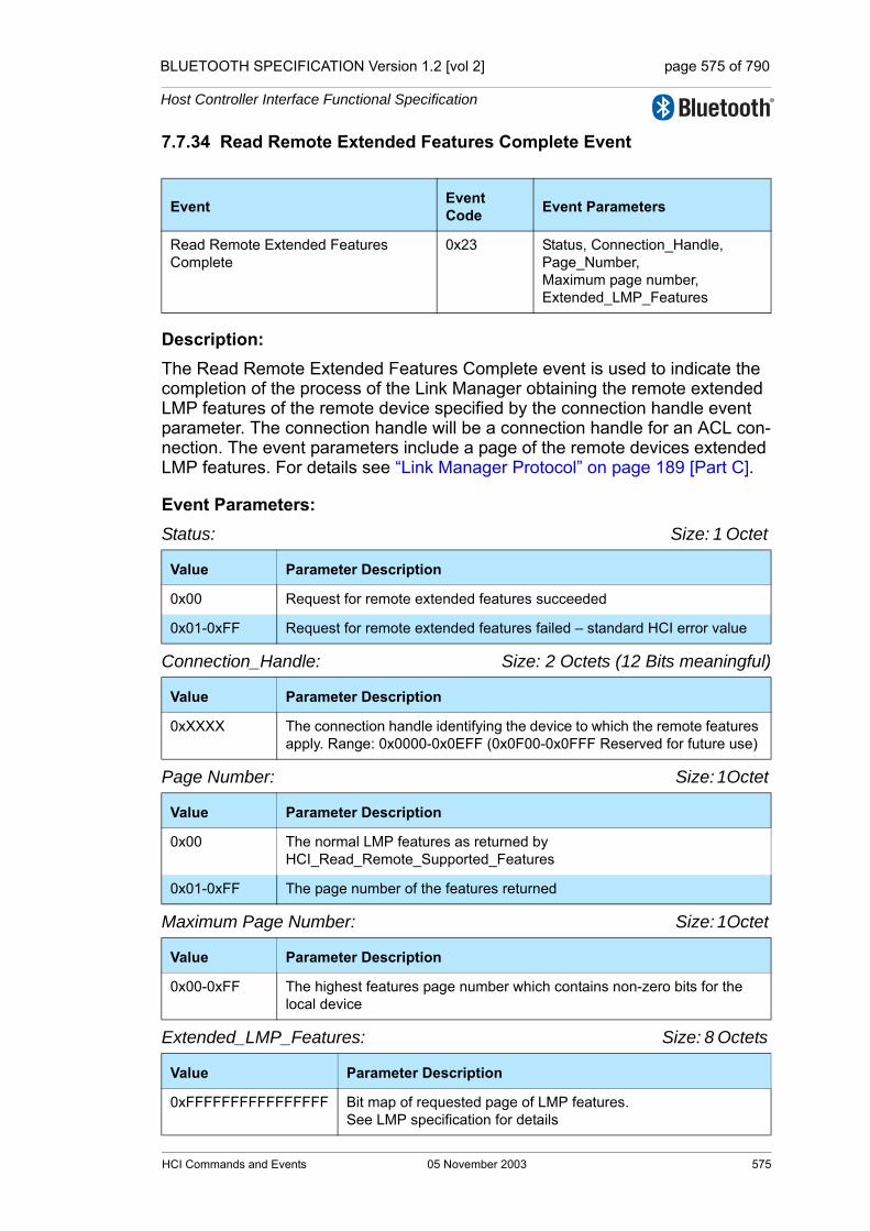
BLUETOOTH SPECIFICATION Version 1.2 [vol 2] page 575 of 790
Host Controller Interface Functional Specification
7.7.34 Read Remote Extended Features Complete Event
Description: The Read Remote Extended Features Complete event is used to indicate the completion of the process of the Link Manager obtaining the remote extended LMP features of the remote device specified by the connection handle event parameter. The connection handle will be a connection handle for an ACL con-nection. The event parameters include a page of the remote devices extended LMP features. For details see “Link Manager Protocol” on page 189 [Part C].
Event Parameters:Status: Size: 1 Octet
Connection_Handle: Size: 2 Octets (12 Bits meaningful)
Page Number: Size: 1Octet
Maximum Page Number: Size: 1Octet
Extended_LMP_Features: Size: 8 Octets
Event Event Code Event Parameters
Read Remote Extended Features Complete
0x23 Status, Connection_Handle, Page_Number, Maximum page number, Extended_LMP_Features
Value Parameter Description
0x00 Request for remote extended features succeeded
0x01-0xFF Request for remote extended features failed – standard HCI error value
Value Parameter Description
0xXXXX The connection handle identifying the device to which the remote features apply. Range: 0x0000-0x0EFF (0x0F00-0x0FFF Reserved for future use)
Value Parameter Description
0x00 The normal LMP features as returned by HCI_Read_Remote_Supported_Features
0x01-0xFF The page number of the features returned
Value Parameter Description
0x00-0xFF The highest features page number which contains non-zero bits for the local device
Value Parameter Description
0xFFFFFFFFFFFFFFFF Bit map of requested page of LMP features. See LMP specification for details
HCI Commands and Events 05 November 2003 575
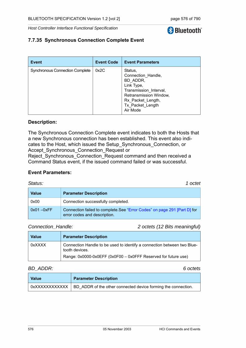
BLUETOOTH SPECIFICATION Version 1.2 [vol 2] page 576 of 790
Host Controller Interface Functional Specification
7.7.35 Synchronous Connection Complete Event
Description:
The Synchronous Connection Complete event indicates to both the Hosts that a new Synchronous connection has been established. This event also indi-cates to the Host, which issued the Setup_Synchronous_Connection, or Accept_Synchronous_Connection_Request or Reject_Synchronous_Connection_Request command and then received a Command Status event, if the issued command failed or was successful.
Event Parameters:
Status: 1 octet
Connection_Handle: 2 octets (12 Bits meaningful)
BD_ADDR: 6 octets
Event Event Code Event Parameters
Synchronous Connection Complete 0x2C Status,Connection_Handle, BD_ADDR, Link Type, Transmission_Interval,Retransmission Window,Rx_Packet_Length, Tx_Packet_LengthAir Mode
Value Parameter Description
0x00 Connection successfully completed.
0x01 –0xFF Connection failed to complete.See “Error Codes” on page 291 [Part D] for error codes and description.
Value Parameter Description
0xXXXX Connection Handle to be used to identify a connection between two Blue-tooth devices. Range: 0x0000-0x0EFF (0x0F00 – 0x0FFF Reserved for future use)
Value Parameter Description
0xXXXXXXXXXXXX BD_ADDR of the other connected device forming the connection.
576 05 November 2003 HCI Commands and Events

BLUETOOTH SPECIFICATION Version 1.2 [vol 2] page 577 of 790
Host Controller Interface Functional Specification
Link_Type: Size: 1 Octet
Transmission_Interval: 1 octets
Retransmission window: 1 octets
Rx_Packet_Length: 2 octets
Tx_Packet_Length: 2 octets
Air Mode: Size: 1 Octet
Value Parameter Description
0x00 SCO Connection
0x01 Reserved
0x02 eSCO Connection
0x03 – 0xFF Reserved
Value Parameter Description
0xXX Time between two consecutive eSCO instants measured in slots. Must be zero for SCO links.
Value Parameter Description
0xXX The size of the retransmission window measured in slots. Must be zero for SCO links.
Value Parameter Description
0xXXXX Length in bytes of the eSCO payload in the receive direction. Must be zero for SCO links.
Value Parameter Description
0xXXXX Length in bytes of the eSCO payload in the transmit direction. Must be zero for SCO links.
Value Parameter Description
0x00 µ-law log
0x01 A-law log
0x02 CVSD
0x03 Transparent Data
0x04 – 0xFF Reserved
HCI Commands and Events 05 November 2003 577

BLUETOOTH SPECIFICATION Version 1.2 [vol 2] page 578 of 790
Host Controller Interface Functional Specification
7.7.36 Synchronous Connection Changed event
Description:
The Synchronous Connection Changed event indicates to the Host that an existing Synchronous connection has been reconfigured. This event also indi-cates to the initiating Host (if the change was host initiated) if the issued com-mand failed or was successful.
Command Parameters:
Status: 1 octet
Connection_Handle: 2 octets (12 Bits meaningful)
Transmission_Interval: 1 octet
Retransmission window: 1 octet
Event Event Code Event Parameters
Synchronous Connection Changed 0x2D Status,Connection_Handle, Transmission_Interval,Retransmission Window,Rx_Packet_Length, Tx_Packet_Length
Value Parameter Description
0x00 Connection successfully reconfigured.
0x01 –0xFF Reconfiguration failed to complete. See “Error Codes” on page 291 [Part D] for error codes and description.
Value Parameter Description
0xXXXX Connection Handle to be used to identify a connection between two Bluetooth devices. Range: 0x0000-0x0EFF (0x0F00 – 0x0FFF Reserved for future use)
Value Parameter Description
0xXX Time between two consecutive SCO/eSCO instants measured in slots.
Value Parameter Description
0xXX The size of the retransmission window measured in slots. Must be zero for SCO links.
578 05 November 2003 HCI Commands and Events
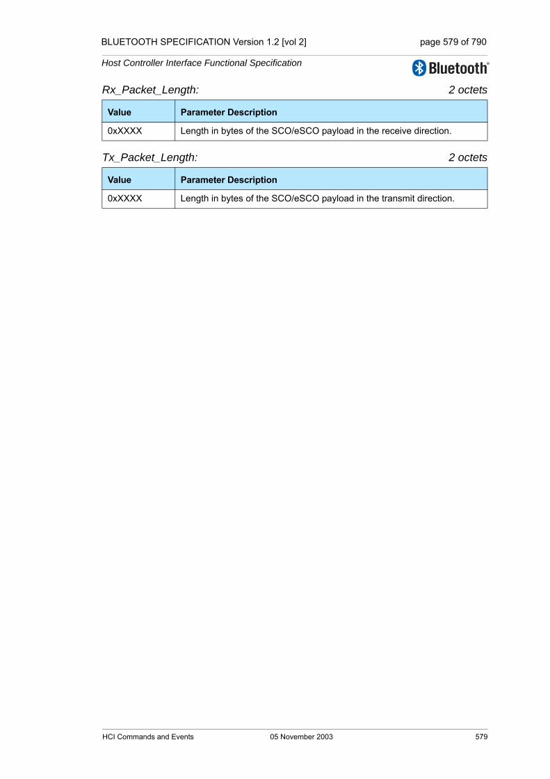
BLUETOOTH SPECIFICATION Version 1.2 [vol 2] page 579 of 790
Host Controller Interface Functional Specification
Rx_Packet_Length: 2 octets
Tx_Packet_Length: 2 octets
Value Parameter Description
0xXXXX Length in bytes of the SCO/eSCO payload in the receive direction.
Value Parameter Description
0xXXXX Length in bytes of the SCO/eSCO payload in the transmit direction.
HCI Commands and Events 05 November 2003 579

BLUETOOTH SPECIFICATION Version 1.2 [vol 2] page 580 of 790
Host Controller Interface Functional Specification
580 05 November 2003 HCI Commands and Events

BLUETOOTH SPECIFICATION Version 1.2 [vol 2] page 581 of 790
Host Controller Interface Functional Specification
8 LIST OF FIGURES
Figure 1.1: Overview of the Lower Software Layers .................................317Figure 1.2: End to End Overview of Lower Software Layers to Transfer
Data .........................................................................................318Figure 5.1: HCI Command Packet ............................................................352Figure 5.2: HCI ACL Data Packet .............................................................353Figure 5.3: HCI Synchronous Data Packet ...............................................355Figure 5.4: HCI Event Packet ....................................................................356Figure 7.1: Local Loopback Mode .............................................................533Figure 7.2: Remote Loopback Mode .........................................................533
List of Figures 05 November 2003 581

BLUETOOTH SPECIFICATION Version 1.2 [vol 2] page 582 of 790
Host Controller Interface Functional Specification
582 05 November 2003 List of Figures

BLUETOOTH SPECIFICATION Version 1.2 [vol 2] page 583 of 790
Host Controller Interface Functional Specification
9 LIST OF TABLES
Table 3.1: Overview of commands and events .........................................321Table 3.2: Generic events .........................................................................322Table 3.3: Controller flow control ..............................................................323Table 3.4: Controller information...............................................................323Table 3.5: Controller configuration............................................................324Table 3.6: Device discovery ......................................................................325Table 3.7: Connection setup .....................................................................327Table 3.8: Remote information..................................................................329Table 3.9: Synchronous connections........................................................330Table 3.10: Connection state ......................................................................331Table 3.11: Piconet structure ......................................................................332Table 3.12: Quality of service......................................................................333Table 3.13: Physical links............................................................................334Table 3.14: Controller flow control. .............................................................335Table 3.15: Link information........................................................................336Table 3.16: Authentication and encryption..................................................337Table 3.17: Testing......................................................................................339Table 3.18: Alphabetical list of commands and events. ..............................340
10 APPENDIX
List of Tables 05 November 2003 583

BLUETOOTH SPECIFICATION Version 1.2 [vol 2] page 584 of 790
Host Controller Interface Functional Specification
584 05 November 2003 Appendix

BLUETOOTH SPECIFICATION Version 1.2 [vol 2] page 585 of 790
Host Controller Interface Functional Specification
APPENDIX A: DEPRECATED COMMANDS, EVENTS AND CONFIGURATION PARAMETERS
Commands, events and configuration parameters in this section were in prior versions of the specification, but have been determined not to be required.
They may be implemented by a controller to allow for backwards compatibility with a host utilizing a prior version of the specification.
A host should not use these commands.
Contents:Page Scan Mode .........................................................................................658
Read Page Scan Mode Command ............................................................659Write Page Scan Mode Command ............................................................660Read Country Code Command .................................................................661Add SCO Connection Command ..............................................................662
Page Scan Mode Change Event ................................................................664
Appendix 05 November 2003 585
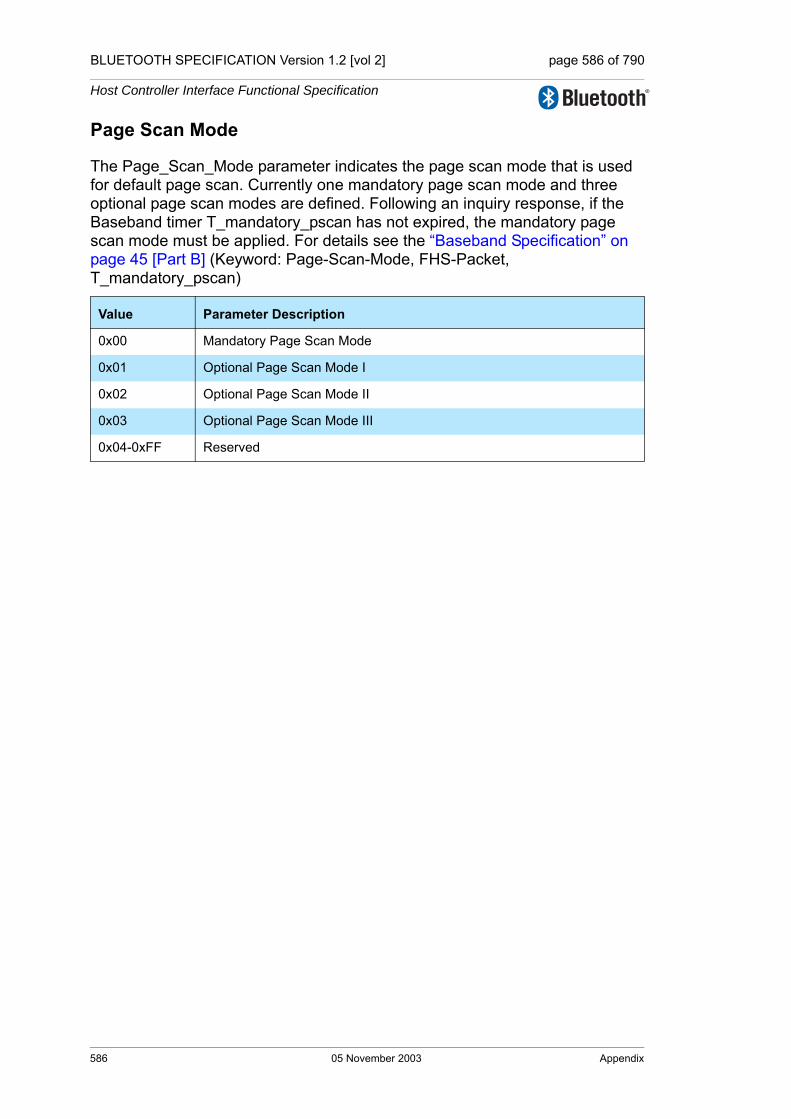
BLUETOOTH SPECIFICATION Version 1.2 [vol 2] page 586 of 790
Host Controller Interface Functional Specification
Page Scan Mode
The Page_Scan_Mode parameter indicates the page scan mode that is used for default page scan. Currently one mandatory page scan mode and three optional page scan modes are defined. Following an inquiry response, if the Baseband timer T_mandatory_pscan has not expired, the mandatory page scan mode must be applied. For details see the “Baseband Specification” on page 45 [Part B] (Keyword: Page-Scan-Mode, FHS-Packet, T_mandatory_pscan)
Value Parameter Description
0x00 Mandatory Page Scan Mode
0x01 Optional Page Scan Mode I
0x02 Optional Page Scan Mode II
0x03 Optional Page Scan Mode III
0x04-0xFF Reserved
586 05 November 2003 Appendix

BLUETOOTH SPECIFICATION Version 1.2 [vol 2] page 587 of 790
Host Controller Interface Functional Specification
Read Page Scan Mode Command
Description:
This command is used to read the default Page Scan Mode configuration parameter of the local Bluetooth device. See “Page Scan Mode” on page 586..
Command Parameters:
None
Return Parameters:
Status: Size: 1 Octet
Page_Scan_Mode: Size: 1 Octet
Event(s) generated (unless masked away):
When the Read_Page_Scan_Mode command has completed, a Command Complete event will be generated.
Command OGF OCF Command Parameters Return Parameters
HCI_Read_Page_Scan_Mode 0x03 0x003D Status,Page_Scan_Mode
Value Parameter Description
0x00 Read_Page_Scan_Mode command succeeded.
0x01-0xFF Read_Page_Scan_Mode command failed. See “Error Codes” on page 291 [Part D] for list of Error Codes.
Value Parameter Description
See Appendix A, “Page Scan Mode” on page 586.
Appendix 05 November 2003 587

BLUETOOTH SPECIFICATION Version 1.2 [vol 2] page 588 of 790
Host Controller Interface Functional Specification
Write Page Scan Mode Command
OGF: 0x03 (Controller and baseband commands)
Description:
This command is used to write the default Page Scan Mode configuration parameter of the local Bluetooth device. See “Page Scan Mode” on page 586.
Command Parameters:
Page_Scan_Mode: Size: 1 Octet
Return Parameters:
Status: Size: 1 Octet
Event(s) generated (unless masked away):
When the Write_Page_Scan_Mode command has completed, a Command Complete event will be generated.
Command OGF OCF Command Parameters Return Parameters
HCI_Write_Page_Scan_Mode 0x03 0x003E Page_Scan_Mode Status
Value Parameter Description
See Appendix A, “Page Scan Mode” on page 586.
Value Parameter Description
0x00 Write_Page_Scan_Mode command succeeded.
0x01-0xFF Write_Page_Scan_Mode command failed. See “Error Codes” on page 291 [Part D] for list of Error Codes.
588 05 November 2003 Appendix
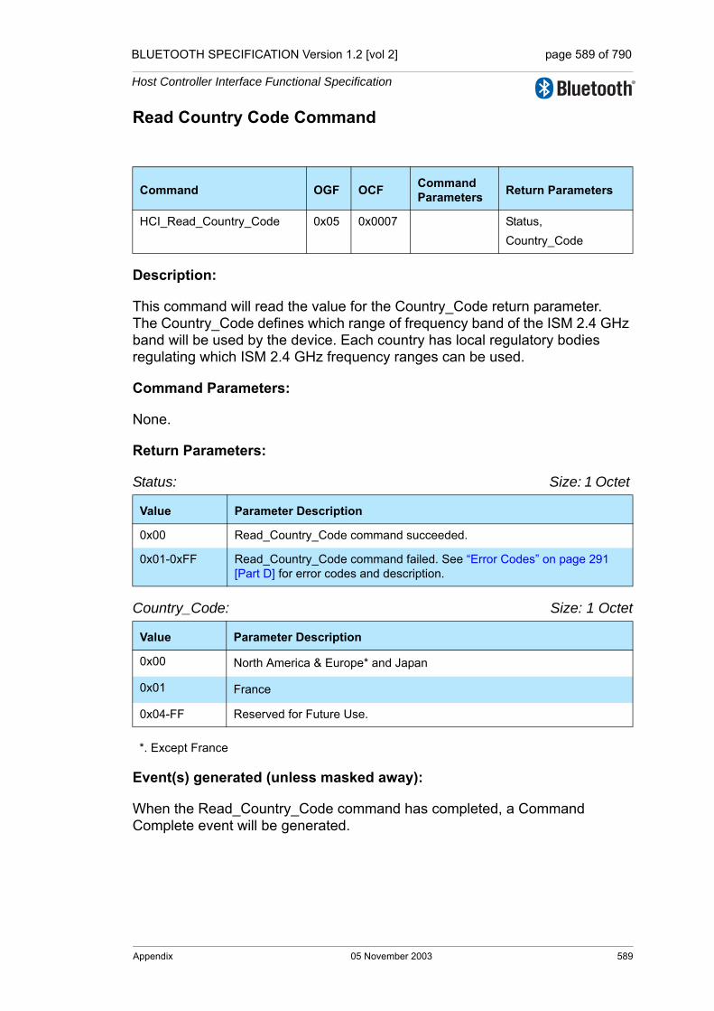
BLUETOOTH SPECIFICATION Version 1.2 [vol 2] page 589 of 790
Host Controller Interface Functional Specification
Read Country Code Command
Description:
This command will read the value for the Country_Code return parameter. The Country_Code defines which range of frequency band of the ISM 2.4 GHz band will be used by the device. Each country has local regulatory bodies regulating which ISM 2.4 GHz frequency ranges can be used.
Command Parameters:
None.
Return Parameters:
Status: Size: 1 Octet
Country_Code: Size: 1 Octet
*. Except France
Event(s) generated (unless masked away):
When the Read_Country_Code command has completed, a Command Complete event will be generated.
Command OGF OCF Command Parameters Return Parameters
HCI_Read_Country_Code 0x05 0x0007 Status,Country_Code
Value Parameter Description
0x00 Read_Country_Code command succeeded.
0x01-0xFF Read_Country_Code command failed. See “Error Codes” on page 291 [Part D] for error codes and description.
Value Parameter Description
0x00 North America & Europe* and Japan
0x01 France
0x04-FF Reserved for Future Use.
Appendix 05 November 2003 589

BLUETOOTH SPECIFICATION Version 1.2 [vol 2] page 590 of 790
Host Controller Interface Functional Specification
Add SCO Connection Command
Description:
This command will cause the link manager to create a SCO connection using the ACL connection specified by the Connection_Handle command parameter. This command causes the local Bluetooth device to create a SCO connection. The Link Manager will determine how the new connection is established. This connection is determined by the current state of the device, its piconet, and the state of the device to be connected. The Packet_Type command parameter specifies which packet types the Link Manager should use for the connection. The Link Manager must only use the packet type(s) specified by the Packet_Type command parameter for sending HCI SCO Data Packets. Multi-ple packet types may be specified for the Packet_Type command parameter by performing a bitwise OR operation of the different packet types. The Link Man-ager may choose which packet type is to be used from the list of acceptable packet types. A Connection Handle for this connection is returned in the Con-nection Complete event (see below).Note: An SCO connection can only be created when an ACL connection already exists and when it is not put in park. For a definition of the different packet types, see the “Baseband Specification” on page 45 [Part B].
Note: At least one packet type must be specified. The Host should enable as many packet types as possible for the Link Manager to perform efficiently. However, the Host must not enable packet types that the local device does not support.
Command Parameters:
Connection_Handle Size 2 Octets (12 Bits meaningful)
Command OGF OCF Command Parameters
Return Parameters
HCI_Add_SCO_Connection 0x01 0x0007 Connection_Handle,Packet_Type
Value Parameter Description
0xXXXX Connection Handle for the ACL connection being used to create an SCO connection.Range: 0x0000-0x0EFF (0x0F00 - 0x0FFF Reserved for future use)
590 05 November 2003 Appendix
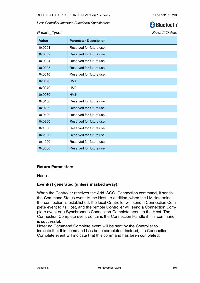
BLUETOOTH SPECIFICATION Version 1.2 [vol 2] page 591 of 790
Host Controller Interface Functional Specification
Packet_Type: Size: 2 Octets
Return Parameters:
None.
Event(s) generated (unless masked away):
When the Controller receives the Add_SCO_Connection command, it sends the Command Status event to the Host. In addition, when the LM determines the connection is established, the local Controller will send a Connection Com-plete event to its Host, and the remote Controller will send a Connection Com-plete event or a Synchronous Connection Complete event to the Host. The Connection Complete event contains the Connection Handle if this command is successful. Note: no Command Complete event will be sent by the Controller to indicate that this command has been completed. Instead, the Connection Complete event will indicate that this command has been completed.
Value Parameter Description
0x0001 Reserved for future use.
0x0002 Reserved for future use.
0x0004 Reserved for future use.
0x0008 Reserved for future use.
0x0010 Reserved for future use.
0x0020 HV1
0x0040 HV2
0x0080 HV3
0x0100 Reserved for future use.
0x0200 Reserved for future use.
0x0400 Reserved for future use.
0x0800 Reserved for future use.
0x1000 Reserved for future use.
0x2000 Reserved for future use.
0x4000 Reserved for future use.
0x8000 Reserved for future use.
Appendix 05 November 2003 591

BLUETOOTH SPECIFICATION Version 1.2 [vol 2] page 592 of 790
Host Controller Interface Functional Specification
Page Scan Mode Change Event
Description:
The Page Scan Mode Change event indicates that the connected remote Blue-tooth device with the specified BD_ADDR has successfully changed the Page_Scan_Mode.
Event Parameters:
BD_ADDR: Size: 6 Octets
Page_Scan_Mode: Size: 1 Octet
Event Event Code Event Parameters
Page Scan Mode Change 0x1F BD_ADDR, Page_Scan_Mode
Value Parameter Description
0xXXXXXXXXXXXX
BD_ADDR of the remote device.
Value Parameter Description
0x00 Mandatory Page Scan Mode.
0x01 Optional Page Scan Mode I.
0x02 Optional Page Scan Mode II.
0x03 Optional Page Scan Mode III.
0x04 – 0xFF Reserved.
592 05 November 2003 Appendix

Core System Package [Controller volume]
Part FMESSAGE SEQUENCE CHARTSBetween Host and Host Controller/Link Manager
Examples of interactions between Host Controller Interface Commands and Events and Link Manager Protocol Data Units are represented in the form of message sequence charts. These charts show typical interactions and do not indicate all possible protocol behavior.

BLUETOOTH SPECIFICATION Version 1.2 [vol 2] page 594 of 790
Message Sequence Charts
594 05 November 2003

BLUETOOTH SPECIFICATION Version 1.2 [vol 2] page 595 of 790
Message Sequence Charts
CONTENTS
1 1Introduction ....................................................................................5991.1 Notation....................................................................................5991.2 Flow of Control .........................................................................6001.3 Example MSC ..........................................................................600
2 Services Without Connection Request ..........................................6012.1 Remote Name Request............................................................601
Step 1: ....................................................................................601Step 2a: ...................................................................................601Step 2b: ...................................................................................602
2.2 One-time Inquiry.......................................................................602Step 1: ....................................................................................602Step 2: ....................................................................................603Step 3a: ...................................................................................603Step 3b: ...................................................................................604
2.3 Periodic Inquiry ........................................................................604Step 1: ....................................................................................604Step 2: ....................................................................................605Step 3: ....................................................................................605Step 4: ....................................................................................605
3 ACL Connection Establishment and Detachment.........................6073.1 Connection Setup ....................................................................608
Step 1: ....................................................................................608Step 2: ....................................................................................608Step 3: ....................................................................................608Step 4a: ...................................................................................609Step 4b: ...................................................................................609Step 4c: ...................................................................................610Step 5: ....................................................................................610Step 6: ....................................................................................611Step 7a: ...................................................................................612Step 7b: ...................................................................................613Step 8: ....................................................................................613Step 9: ....................................................................................614Step 10: ...................................................................................614
05 November 2003 595

BLUETOOTH SPECIFICATION Version 1.2 [vol 2] page 596 of 790
Message Sequence Charts
4 Optional Activities After ACL Connection Establishment............6154.1 Authentication Requested........................................................615
Step 1: ....................................................................................6154.2 Set Connection Encryption ......................................................616
Step 1: ....................................................................................616Step 2: ....................................................................................616
4.3 Change Connection Link Key ..................................................617Step 1: ....................................................................................617
4.4 Master Link Key .......................................................................618Step 1: ....................................................................................618Step 2: ....................................................................................619
4.5 Read Remote Supported Features..........................................620Step 1: ....................................................................................620
4.6 Read Remote Extended Features ..........................................620Step 1: ....................................................................................620
4.7 Read Clock Offset....................................................................621Step 1: ....................................................................................621
4.8 Read Remote Version Information...........................................621Step 1: ....................................................................................621
4.9 QOS Setup ..............................................................................622Step 1: ....................................................................................622
4.10 Switch Role..............................................................................622Step 1a: ..................................................................................622Step 1b: ..................................................................................623Step 2: ....................................................................................623
5 Synchronous Connection Establishment and Detachment.........6255.1 Synchronous Connection Setup ..............................................625
Step 1a: ..................................................................................625Step 1b: ..................................................................................626Step 1c: ...................................................................................626Step 1d: ..................................................................................627Step 1e: ..................................................................................627Step 2a: ..................................................................................628Step 2b: ..................................................................................628Step 3a: ..................................................................................629Step 3b: ..................................................................................629
596 05 November 2003
BLUETOOTH SPECIFICATION Version 1.2 [vol 2] page 597 of 790
Message Sequence Charts
6 Sniff, Hold and Park .........................................................................6316.1 Sniff Mode ................................................................................631
Step 1: ....................................................................................631Step 2: ....................................................................................631
6.2 Hold Mode................................................................................632Step 1a: ...................................................................................632Step 1b: ...................................................................................632Step 1c: ...................................................................................633Step 2: ....................................................................................633
6.3 Park State.................................................................................634Step 1a: ...................................................................................634Step 1b: ...................................................................................634Step 2: ....................................................................................635Step 3a: ...................................................................................635Step 3b: ...................................................................................636
7 Buffer Management, Flow Control..................................................637Step 1: ....................................................................................637Step 2: ....................................................................................638
8 Loopback Mode................................................................................6398.1 Local Loopback Mode..............................................................639
Step 1: ....................................................................................639Step 2a: ...................................................................................639Step 2b: ...................................................................................640Step 3: ....................................................................................640
8.2 Remote Loopback Mode..........................................................641Step 1: ....................................................................................641Step 2: ....................................................................................641Step 3: ....................................................................................642
9 List of Figures...................................................................................643
05 November 2003 597

BLUETOOTH SPECIFICATION Version 1.2 [vol 2] page 598 of 790
Message Sequence Charts
598 05 November 2003
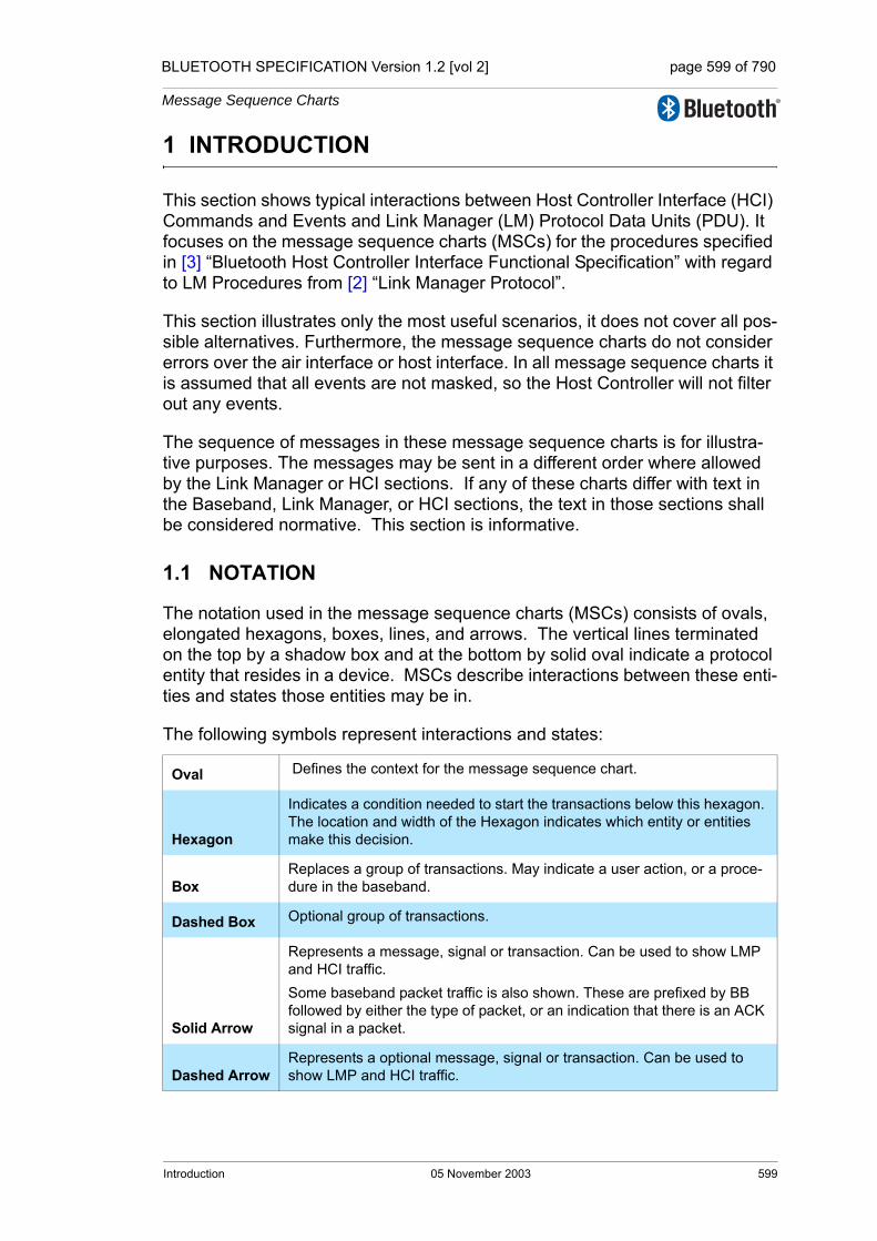
BLUETOOTH SPECIFICATION Version 1.2 [vol 2] page 599 of 790
Message Sequence Charts
1 INTRODUCTION
This section shows typical interactions between Host Controller Interface (HCI) Commands and Events and Link Manager (LM) Protocol Data Units (PDU). It focuses on the message sequence charts (MSCs) for the procedures specified in [3] “Bluetooth Host Controller Interface Functional Specification” with regard to LM Procedures from [2] “Link Manager Protocol”.
This section illustrates only the most useful scenarios, it does not cover all pos-sible alternatives. Furthermore, the message sequence charts do not consider errors over the air interface or host interface. In all message sequence charts it is assumed that all events are not masked, so the Host Controller will not filter out any events.
The sequence of messages in these message sequence charts is for illustra-tive purposes. The messages may be sent in a different order where allowed by the Link Manager or HCI sections. If any of these charts differ with text in the Baseband, Link Manager, or HCI sections, the text in those sections shall be considered normative. This section is informative.
1.1 NOTATION
The notation used in the message sequence charts (MSCs) consists of ovals, elongated hexagons, boxes, lines, and arrows. The vertical lines terminated on the top by a shadow box and at the bottom by solid oval indicate a protocol entity that resides in a device. MSCs describe interactions between these enti-ties and states those entities may be in.
The following symbols represent interactions and states:
Oval Defines the context for the message sequence chart.
Hexagon
Indicates a condition needed to start the transactions below this hexagon. The location and width of the Hexagon indicates which entity or entities make this decision.
BoxReplaces a group of transactions. May indicate a user action, or a proce-dure in the baseband.
Dashed Box Optional group of transactions.
Solid Arrow
Represents a message, signal or transaction. Can be used to show LMP and HCI traffic.Some baseband packet traffic is also shown. These are prefixed by BB followed by either the type of packet, or an indication that there is an ACK signal in a packet.
Dashed ArrowRepresents a optional message, signal or transaction. Can be used to show LMP and HCI traffic.
Introduction 05 November 2003 599
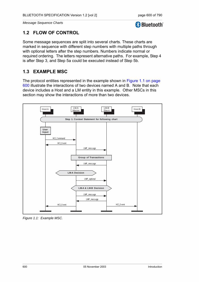
BLUETOOTH SPECIFICATION Version 1.2 [vol 2] page 600 of 790
Message Sequence Charts
1.2 FLOW OF CONTROL
Some message sequences are split into several charts. These charts are marked in sequence with different step numbers with multiple paths through with optional letters after the step numbers. Numbers indicate normal or required ordering. The letters represent alternative paths. For example, Step 4 is after Step 3, and Step 5a could be executed instead of Step 5b.
1.3 EXAMPLE MSC
The protocol entities represented in the example shown in Figure 1.1 on page 600 illustrate the interactions of two devices named A and B. Note that each device includes a Host and a LM entity in this example. Other MSCs in this section may show the interactions of more than two devices.
Figure 1.1: Example MSC.
LM-AMaster
LM-BSlav e
Host A Host B
Group of Transactions
LMP_message
LMP_message
HCI_Event
HCI_Command
LMP_optional
LM-A Decision
LM-A & LM-B Decision
LMP_message
LMP_message
HCI_Event HCI_Event
UserInput
Step 1: Context Statement for following chart
600 05 November 2003 Introduction
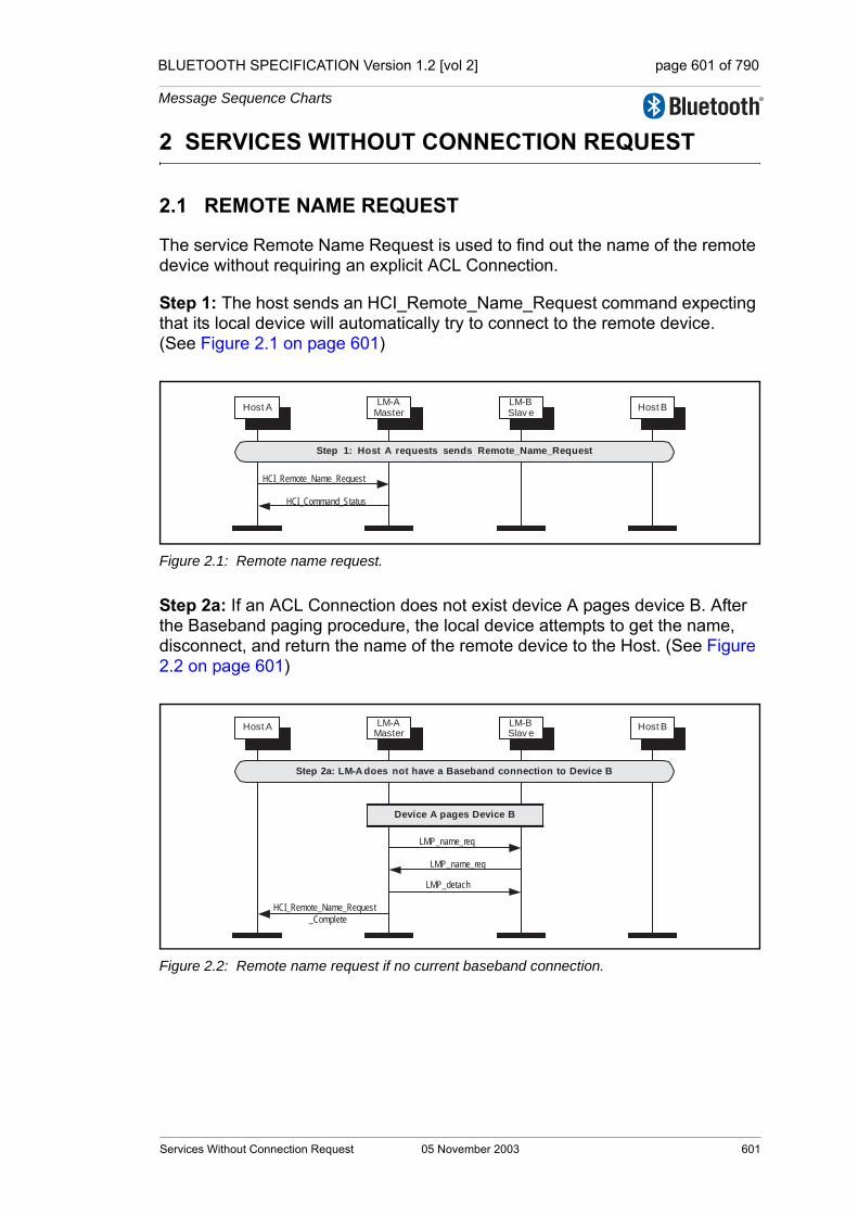
BLUETOOTH SPECIFICATION Version 1.2 [vol 2] page 601 of 790
Message Sequence Charts
2 SERVICES WITHOUT CONNECTION REQUEST
2.1 REMOTE NAME REQUEST
The service Remote Name Request is used to find out the name of the remote device without requiring an explicit ACL Connection.
Step 1: The host sends an HCI_Remote_Name_Request command expecting that its local device will automatically try to connect to the remote device. (See Figure 2.1 on page 601)
Figure 2.1: Remote name request.
Step 2a: If an ACL Connection does not exist device A pages device B. After the Baseband paging procedure, the local device attempts to get the name, disconnect, and return the name of the remote device to the Host. (See Figure 2.2 on page 601)
Figure 2.2: Remote name request if no current baseband connection.
HCI_Remote_Name_Request
LM-AMaster
LM-BSlav e
Host A Host B
HCI_Command_Status
Step 1: Host A requests sends Remote_Name_Request
LM-AMaster
LM-BSlav e
Host A Host B
Device A pages Device B
LMP_name_req
LMP_name_req
LMP_detach
HCI_Remote_Name_Request
_Complete
Step 2a: LM-A does not have a Baseband connection to Device B
Services Without Connection Request 05 November 2003 601

BLUETOOTH SPECIFICATION Version 1.2 [vol 2] page 602 of 790
Message Sequence Charts
Step 2b: If an ACL Connection exists when the request is made, then the Remote Name Request procedure will be executed like an optional service. No Paging and no ACL disconnect is done. (See Figure 2.3 on page 602)
Figure 2.3: Remote name request with baseband connection.
2.2 ONE-TIME INQUIRY
Inquiry is used to detect and collect nearby devices.
Step 1: The host sends an HCI_Inquiry command. (See Figure 2.4 on page 602)
Figure 2.4: Host A starts inquiry procedure.
LM-A⇒BB-A Master
LM-B⇒BB-B Master
Host A Host B
LMP_name_req
LMP_name_req
HCI_Remote_Name_Request
_Complete
Step 2b: LM-A already has a Baseband connection to Device B
HCI_Inquiry
Host A BB-C
HCI_Command_Status
Step 1: Host A starts Inquiry Procedure
LM-A⇒BB-A Master
LM-B⇒BB-B Master
602 05 November 2003 Services Without Connection Request
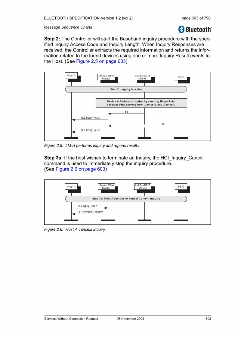
BLUETOOTH SPECIFICATION Version 1.2 [vol 2] page 603 of 790
Message Sequence Charts
Step 2: The Controller will start the Baseband inquiry procedure with the spec-ified Inquiry Access Code and Inquiry Length. When Inquiry Responses are received, the Controller extracts the required information and returns the infor-mation related to the found devices using one or more Inquiry Result events to the Host. (See Figure 2.5 on page 603)
Figure 2.5: LM-A performs inquiry and reports result..
Step 3a: If the host wishes to terminate an Inquiry, the HCI_Inquiry_Cancel command is used to immediately stop the inquiry procedure. (See Figure 2.6 on page 603)
Figure 2.6: Host A cancels inquiry.
Host ABB-C
Device A Performs Inquiry by sending ID packets,
receives FHS packets from Device B and Device C
BB
BB
HCI_Inquiry_Result
HCI_Inquiry_Result
Step 2: Inquiry is active
LM-A⇒BB-A Master
LM-B⇒BB-B Master
Host A BB-C
HCI_Inquiry_Cancel
HCI_Command_Complete
Step 3a: Host A decides to cancel Current Inquiry
LM-A⇒BB-A Master
LM-B⇒BB-B Master
Services Without Connection Request 05 November 2003 603
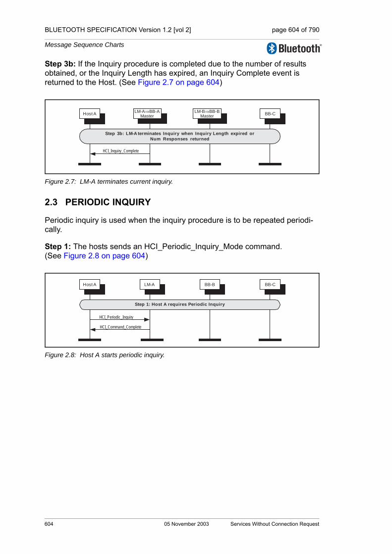
BLUETOOTH SPECIFICATION Version 1.2 [vol 2] page 604 of 790
Message Sequence Charts
Step 3b: If the Inquiry procedure is completed due to the number of results obtained, or the Inquiry Length has expired, an Inquiry Complete event is returned to the Host. (See Figure 2.7 on page 604)
Figure 2.7: LM-A terminates current inquiry.
2.3 PERIODIC INQUIRY
Periodic inquiry is used when the inquiry procedure is to be repeated periodi-cally.
Step 1: The hosts sends an HCI_Periodic_Inquiry_Mode command. (See Figure 2.8 on page 604)
Figure 2.8: Host A starts periodic inquiry.
Host A BB-C
HCI_Inquiry_Complete
Step 3b: LM-A terminates Inquiry when Inquiry Length expired or
Num Responses returned
LM-A⇒BB-A Master
LM-B⇒BB-B Master
HCI_Periodic_Inquiry
LM-A BB-BHost A BB-C
HCI_Command_Complete
Step 1: Host A requires Periodic Inquiry
604 05 November 2003 Services Without Connection Request

BLUETOOTH SPECIFICATION Version 1.2 [vol 2] page 605 of 790
Message Sequence Charts
Step 2: The Controller will start a periodic Inquiry. In the inquiry cycle, one or several Inquiry Result events will be returned. (See Figure 2.9 on page 605)
Figure 2.9: LM-A periodically performs an inquiry and reports result.
Step 3: An Inquiry Complete event will be returned to the Host when the cur-rent periodic inquiry has finished. (See Figure 2.10 on page 605)
Figure 2.10: LM-A terminates current inquiry.
Step 4: The periodic Inquiry can be stopped using the HCI_Exit_Periodic_Inquiry_Mode command. (See Figure 2.11 on page 605)
Figure 2.11: Host A decides to exit periodic inquiry.
LM-A BB-BHost A BB-C
Device A Performs Inquiry
Receives FHS packets from Device B and Device C
BB
BB
HCI_Inquiry_Result
HCI_Inquiry_Result
Step 2: Periodically an Inquiry is Performed
LM-A BB-BHost A BB-C
HCI_Inquiry_Complete
Step 3: LM-A terminates Inquiry when Inquiry Length or Num Responses reached
LM-A BB-BHost A BB-C
HCI_Ex it_Periodic_Inquiry
HCI_Command_Complete
Step 3: Host A decides to cancel Current Periodic Inquiry
Services Without Connection Request 05 November 2003 605

BLUETOOTH SPECIFICATION Version 1.2 [vol 2] page 606 of 790
Message Sequence Charts
606 05 November 2003 Services Without Connection Request
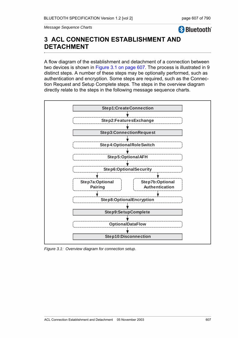
BLUETOOTH SPECIFICATION Version 1.2 [vol 2] page 607 of 790
Message Sequence Charts
3 ACL CONNECTION ESTABLISHMENT AND DETACHMENT
A flow diagram of the establishment and detachment of a connection between two devices is shown in Figure 3.1 on page 607. The process is illustrated in 9 distinct steps. A number of these steps may be optionally performed, such as authentication and encryption. Some steps are required, such as the Connec-tion Request and Setup Complete steps. The steps in the overview diagram directly relate to the steps in the following message sequence charts.
Figure 3.1: Overview diagram for connection setup.
Step 1: Create Connection
Step 9: Setup Complete
Step 10: Disconnection
Step 5: Optional AFH
Step 4: Optional Role Switch
Step 7a: Optional
Pairing
Step 7b: Optional
Authentication
Step 8: Optional Encryption
Optional Data Flow
Step 2: Features Exchange
Step 3: Connection Request
Step 6: Optional Security
ACL Connection Establishment and Detachment 05 November 2003 607
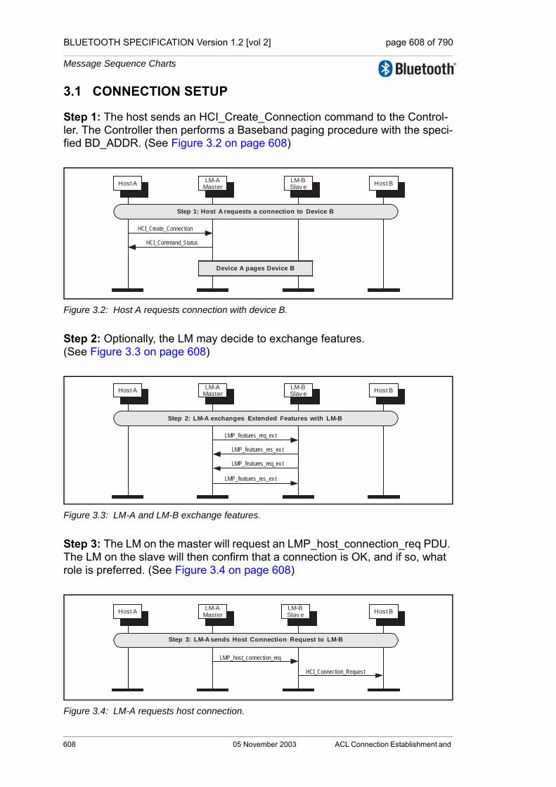
BLUETOOTH SPECIFICATION Version 1.2 [vol 2] page 608 of 790
Message Sequence Charts
3.1 CONNECTION SETUP
Step 1: The host sends an HCI_Create_Connection command to the Control-ler. The Controller then performs a Baseband paging procedure with the speci-fied BD_ADDR. (See Figure 3.2 on page 608)
Figure 3.2: Host A requests connection with device B.
Step 2: Optionally, the LM may decide to exchange features. (See Figure 3.3 on page 608)
Figure 3.3: LM-A and LM-B exchange features.
Step 3: The LM on the master will request an LMP_host_connection_req PDU. The LM on the slave will then confirm that a connection is OK, and if so, what role is preferred. (See Figure 3.4 on page 608)
Figure 3.4: LM-A requests host connection.
HCI_Create_Connection
LM-AMaster
LM-BSlav e
Host A Host B
HCI_Command_Status
Device A pages Device B
Step 1: Host A requests a connection to Device B
LMP_features_req_ex t
LM-AMaster
LM-BSlav e
Host A Host B
LMP_features_res_ex t
LMP_features_res_ex t
LMP_features_req_ex t
Step 2: LM-A exchanges Extended Features with LM-B
LMP_host_connection_req
LM-AMaster
LM-BSlav e
Host A Host B
HCI_Connection_Request
Step 3: LM-A sends Host Connection Request to LM-B
608 05 November 2003 ACL Connection Establishment and

BLUETOOTH SPECIFICATION Version 1.2 [vol 2] page 609 of 790
Message Sequence Charts
Step 4a: The remote host rejects this connection, and the link is terminated. (See Figure 3.5 on page 609)
Figure 3.5: Device B rejects connection request.
Step 4b: The remote host accepts this connection. (See Figure 3.6 on page 609)
Figure 3.6: Device B accepts connection request.
LMP_not_accepted
LM-AMaster
LM-BSlav e
Host A Host B
HCI_Reject_Connection_Request
LMP_detach
HCI_Connection_Complete
(Host Rejected)
HCI_Connection_Complete
(Host Rejected)
Step 4a: LM-B rejects Connection Request from LM-A
LMP_accepted
LM-AMaster
LM-BSlav e
Host A Host B
HCI_Accept_Connection_Request
(Slave Preferred)
HCI_Command_Status
Step 4b: LM-B accepts Connection Request from LM-A as a slave
ACL Connection Establishment and Detachment 05 November 2003 609

BLUETOOTH SPECIFICATION Version 1.2 [vol 2] page 610 of 790
Message Sequence Charts
Step 4c: The remote host accepts this connection but with the preference of being a master. This will cause a role switch to occur before the LMP_accepted for the LMP_host_connection_req PDU is sent. (See Figure 3.7 on page 610)
Figure 3.7: Device B accepts connection requests as master.
Step 5: After the features have been exchanged and AFH support is deter-mined to be available, the master may at any time send an LMP_set_AFH and LMP_channel_classification_req PDU. (See Figure 3.8 on page 610)
Figure 3.8: LM-A starts adaptive frequency hopping.
LMP_slot_offset
LM-AMaster
LM-BSlav e
Host A Host B
HCI_Accept_Connection_Request
(Master Preferred)
LMP_switch_req
LMP_accepted
HCI_Command_Status
Role Switch
LMP_accepted
(LMP_host_connection_req)HCI_Role_Change (Master)HCI_Role_Change (Slave)
Step 4c: LM-B accepts Connection Request from LM-A as a master
LM-AMaster
LM-BSlav e
Host A Host B
LMP_set_AFH
Step 5: LM-A may enable AFH
LMP_channel_classification_req
LM-A may enable channel classification
LMP_channel_classification
LMP_channel_classification
610 05 November 2003 ACL Connection Establishment and

BLUETOOTH SPECIFICATION Version 1.2 [vol 2] page 611 of 790
Message Sequence Charts
Step 6: The LM will request if authentication is required. It does this by requesting the Link Key for this connection from the Host. (See Figure 3.9 on page 611)
Figure 3.9: Authentication initiated.
LM-AMaster
LM-BSlav e
Host A Host B
HCI_Link_Key_Request
Step 6: Authentication required
ACL Connection Establishment and Detachment 05 November 2003 611

BLUETOOTH SPECIFICATION Version 1.2 [vol 2] page 612 of 790
Message Sequence Charts
Step 7a: If authentication is required by the higher layers and the devices to be connected do not have a common link key, a pairing procedure will be used. The LM will have requested a link key from the host for this connection. If there is a negative reply, then a PIN code will be requested. This PIN code will be requested on both sides of the connection, and authentication performed based on this PIN code. The last step is for the new link key for this connection is passed to the host so that it may store it for future connections. (See Figure 3.10 on page 612)
Figure 3.10: Pairing during connection setup.
LMP_accepted
LM-AMaster
LM-BSlav e
Host A Host B
LMP_in_rand
HCI_PIN_Code_Request
HCI_PIN_Code_Request_Reply
HCI_Command_Complete
HCI_Link_Key_Request_Negative_Reply
HCI_Command_Complete
HCI_PIN_Code_Request
HCI_Command_Complete
HCI_PIN_Code_Request_Reply
LMP_comb_key
LMP_sres
LMP_au_rand
LMP_comb_key
LMP_au_rand
LMP_sres
HCI_Link_Key_NotificationHCI_Link_Key_Notification
UserInputs PIN
Code
UserInputs PIN
Code
Step 6a: Pairing during connection establishment
612 05 November 2003 ACL Connection Establishment and
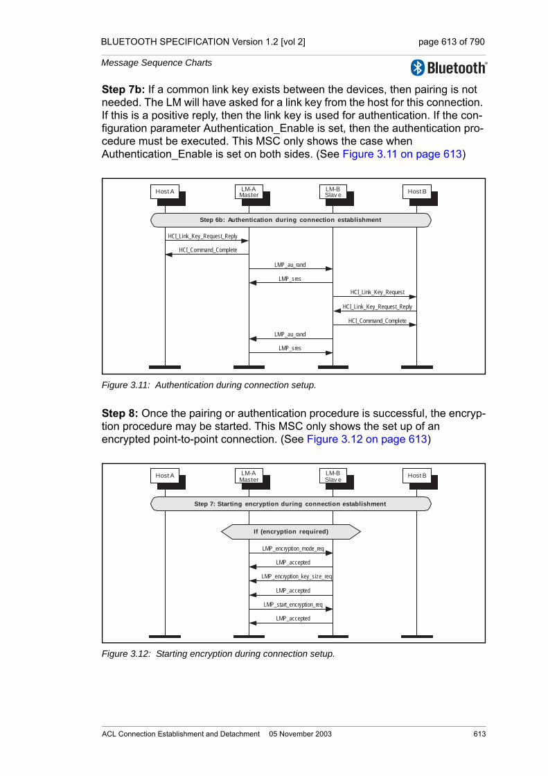
BLUETOOTH SPECIFICATION Version 1.2 [vol 2] page 613 of 790
Message Sequence Charts
Step 7b: If a common link key exists between the devices, then pairing is not needed. The LM will have asked for a link key from the host for this connection. If this is a positive reply, then the link key is used for authentication. If the con-figuration parameter Authentication_Enable is set, then the authentication pro-cedure must be executed. This MSC only shows the case when Authentication_Enable is set on both sides. (See Figure 3.11 on page 613)
Figure 3.11: Authentication during connection setup.
Step 8: Once the pairing or authentication procedure is successful, the encryp-tion procedure may be started. This MSC only shows the set up of an encrypted point-to-point connection. (See Figure 3.12 on page 613)
Figure 3.12: Starting encryption during connection setup.
LM-AMaster
LM-BSlav e
Host A Host B
HCI_Link_Key_Request_Reply
HCI_Command_Complete
LMP_sres
LMP_au_rand
LMP_au_rand
LMP_sres
HCI_Link_Key_Request
HCI_Link_Key_Request_Reply
HCI_Command_Complete
Step 6b: Authentication during connection establishment
LM-AMaster
LM-BSlav e
Host A Host B
If (encryption required)
LMP_accepted
LMP_encryption_key_size_req
LMP_encryption_mode_req
LMP_accepted
LMP_accepted
LMP_start_encryption_req
Step 7: Starting encryption during connection establishment
ACL Connection Establishment and Detachment 05 November 2003 613
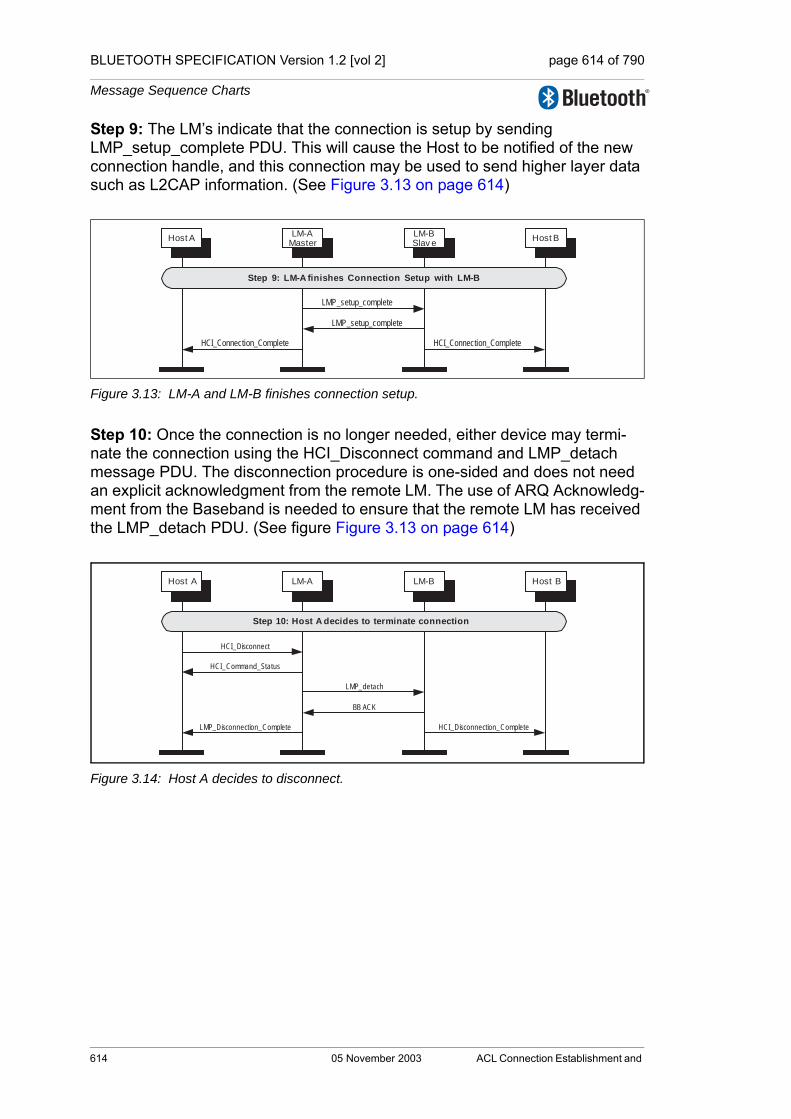
BLUETOOTH SPECIFICATION Version 1.2 [vol 2] page 614 of 790
Message Sequence Charts
Step 9: The LM’s indicate that the connection is setup by sending LMP_setup_complete PDU. This will cause the Host to be notified of the new connection handle, and this connection may be used to send higher layer data such as L2CAP information. (See Figure 3.13 on page 614)
Figure 3.13: LM-A and LM-B finishes connection setup.
Step 10: Once the connection is no longer needed, either device may termi-nate the connection using the HCI_Disconnect command and LMP_detach message PDU. The disconnection procedure is one-sided and does not need an explicit acknowledgment from the remote LM. The use of ARQ Acknowledg-ment from the Baseband is needed to ensure that the remote LM has received the LMP_detach PDU. (See figure Figure 3.13 on page 614)
Figure 3.14: Host A decides to disconnect.
LMP_setup_complete
LM-AMaster
LM-BSlav e
Host A Host B
LMP_setup_complete
HCI_Connection_Complete HCI_Connection_Complete
Step 9: LM-A finishes Connection Setup with LM-B
BB ACK
LM-A LM-BHost A Host B
LMP_detach
HCI_Command_Status
HCI_Disconnection_Complete
HCI_Disconnect
LMP_Disconnection_Complete
Step 10: Host A decides to terminate connection
614 05 November 2003 ACL Connection Establishment and

BLUETOOTH SPECIFICATION Version 1.2 [vol 2] page 615 of 790
Message Sequence Charts
4 OPTIONAL ACTIVITIES AFTER ACL CONNECTION ESTABLISHMENT
4.1 AUTHENTICATION REQUESTED
Step 1: Authentication can be explicitly executed at any time after a connection has been established. If no Link Key is available then the Link Key is required from the Host. (See Figure 4.1 on page 615)
Note: If the Controller or LM and the Host do not have the Link Key a PIN Code Request event will be sent to the Host to request a PIN Code for pairing. A pro-cedure identical to that used during Connection Setup (Section 3.1, Step 7a:) will be used. (See Figure 3.9 on page 611)
Figure 4.1: Authentication requested.
HCI_Authentication_Requested
LM-A LM-BHost A Host B
HCI_Command_Status
If (link key missing) thenLink Key Required
HCI_Link_Key_Request
HCI_Link_Key_Request_Reply
HCI_Command_Complete
LMP_sres
LMP_au_rand
HCI_Link_Key_Request
HCI_Link_Key_Request_Reply
HCI_Command_Complete
HCI_Authentication_Complete
Step 1: Host A requests authentication
Optional Activities After ACL Connection Establishment05 November 2003 615

BLUETOOTH SPECIFICATION Version 1.2 [vol 2] page 616 of 790
Message Sequence Charts
4.2 SET CONNECTION ENCRYPTION
Step 1: The host may at any time turn on encryption using the HCI_Set_Connection_Encryption command. This command can be originated from either the master or slave sides. Only the master side is shown in figure 4.2. If this command is sent from a slave, the only difference is that the LMP_encryption_mode_req PDU will be sent from the slave. The LMP_encryption_key_size_req and LMP_start_encryption_req PDUs will always be requested from the master. (See Figure 4.2 on page 616)
Figure 4.2: Encryption requested.
Step 2: To terminate the use of encryption, The HCI_Set_Connection_Encryption command is used. (See Figure 4.3 on page 616)
Figure 4.3: Encryption off requested.
HCI_Set_Connection_Encryption
(on)
LM-AMaster
LM-BSlav e
Host A Host B
HCI_Command_Status
HCI_Encryption_Change (on)
LMP_accepted
LMP_encryption_key_size_req
LMP_encryption_mode_req
LMP_accepted
LMP_accepted
LMP_start_encryption_req
HCI_Encryption_Change (on)
Step 1: Host A requests encryption on
HCI_Set_Connection_Encryption
(off)
LM-A
Master
LM-B
Slav eHost A Host B
HCI_Command_Status
HCI_Encryption_Change (off)
LMP_accepted
LMP_stop_encryption_req
LMP_encryption_mode_req
LMP_accepted
HCI_Encryption_Change (off)
Step 2: Host A requests encryption off
616 05 November 2003 Optional Activities After ACL Connection
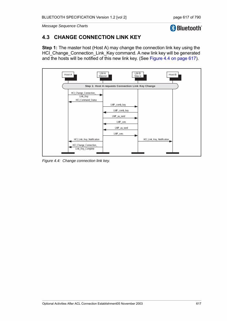
BLUETOOTH SPECIFICATION Version 1.2 [vol 2] page 617 of 790
Message Sequence Charts
4.3 CHANGE CONNECTION LINK KEY
Step 1: The master host (Host A) may change the connection link key using the HCI_Change_Connection_Link_Key command. A new link key will be generated and the hosts will be notified of this new link key. (See Figure 4.4 on page 617).
Figure 4.4: Change connection link key.
HCI_Change_Connection_
Link_Key
LM-AMaster
LM-BSlav e
Host A Host B
HCI_Command_Status
HCI_Link_Key_Notification HCI_Link_Key_Notification
HCI_Change_Connection_
Link_Key_Complete
LMP_comb_key
LMP_sres
LMP_au_rand
LMP_comb_key
LMP_au_rand
LMP_sres
Step 1: Host A requests Connection Link Key Change
Optional Activities After ACL Connection Establishment05 November 2003 617
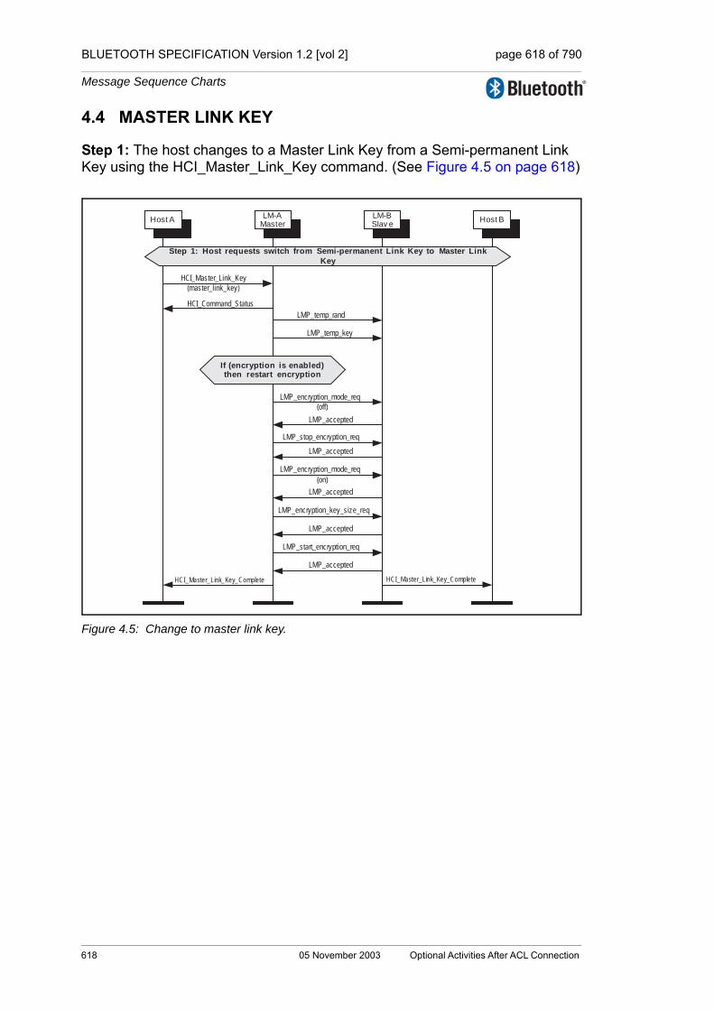
BLUETOOTH SPECIFICATION Version 1.2 [vol 2] page 618 of 790
Message Sequence Charts
4.4 MASTER LINK KEY
Step 1: The host changes to a Master Link Key from a Semi-permanent Link Key using the HCI_Master_Link_Key command. (See Figure 4.5 on page 618)
Figure 4.5: Change to master link key.
HCI_Master_Link_Key
(master_link_key)
Step 1: Host requests switch from Semi-permanent Link Key to Master Link
Key
LM-AMaster
LM-BSlav e
Host A Host B
HCI_Command_Status
LMP_temp_key
LMP_temp_rand
If (encryption is enabled)then restart encryption
LMP_accepted
LMP_stop_encryption_req
LMP_accepted
LMP_accepted
LMP_encryption_key_size_req
LMP_encryption_mode_req
(on)
LMP_accepted
LMP_accepted
LMP_start_encryption_req
HCI_Master_Link_Key_Complete HCI_Master_Link_Key_Complete
LMP_encryption_mode_req
(off)
618 05 November 2003 Optional Activities After ACL Connection

BLUETOOTH SPECIFICATION Version 1.2 [vol 2] page 619 of 790
Message Sequence Charts
Step 2: The host changes to a Semi-permanent Link Key from a Master Link Key using the HCI_Master_Link_Key command. (See Figure 4.6 on page 619)
Figure 4.6: Change to semi permanent link key.
HCI_Master_Link_Key
(semi_permanent_link_key)
LM-AMaster
LM-BSlav e
Host A Host B
HCI_Command_Status
LMP_accepted
LMP_use_semi_permanent_key
If (encryption is enabled)then restart encryption
LMP_accepted
LMP_stop_encryption_req
LMP_accepted
LMP_accepted
LMP_encryption_key_size_req
LMP_encryption_mode_req
(on)
LMP_accepted
LMP_accepted
LMP_start_encryption_req
HCI_Master_Link_Key_Complete HCI_Master_Link_Key_Complete
LMP_encryption_mode_req
(off)
Step 2: Host requests switch from Master Link Key to Semi-permanent Link Key
Optional Activities After ACL Connection Establishment05 November 2003 619

BLUETOOTH SPECIFICATION Version 1.2 [vol 2] page 620 of 790
Message Sequence Charts
4.5 READ REMOTE SUPPORTED FEATURES
Using the HCI_Read_Remote_Supported_Features command the supported LMP Features of a remote device can be read. (See Figure 4.7 on page 620)
If the remote supported features have been obtained previously then the Con-troller may return them without sending any LMP PDUs.
Step 1: The host requests the supported features of a remote device.
Figure 4.7: Read remote supported features.
4.6 READ REMOTE EXTENDED FEATURES
Using the HCI_Read_Remote_Extended_Features command the extended LMP features of a remote device can be read. (See Figure 4.8 on page 620)
If the remote extended features have been obtained previously then the Con-troller may return them without sending any LMP PDUs.
Step 1: The host requests the extended features of a remote device.
Figure 4.8: Read remote extended features.
HCI_Read_Supported_Features
LM-A LM-BHost A Host B
HCI_Command_Status
LMP_features_res
LMP_features_req
HCI_Read_Remote_Supported
_Features_Complete
Step 1: Host A requests Supported Features from Device B
HCI_Read_Remote_Ex tended
_Features
LM-A LM-BHost A Host B
HCI_Command_Status
LMP_features_res_ex t
LMP_features_req_ex t
HCI_Read_Remote_Ex tended
_Features_Complete
Step 1: Host A requests Extended Features from Device B
620 05 November 2003 Optional Activities After ACL Connection

BLUETOOTH SPECIFICATION Version 1.2 [vol 2] page 621 of 790
Message Sequence Charts
4.7 READ CLOCK OFFSET
Using the HCI_Read_Clock_Offset command the device acting as the master can read the Clock Offset of a slave. The Clock Offset can be used to speed up the paging procedure in a later connection attempt. If the command is requested from the slave device, the Controller will directly return a Command Status event and a Read Clock Offset Complete event without sending any LMP PDUs. (See Figure 4.9 on page 621)
Step 1: The host requests the clock offset of a remote device.
Figure 4.9: Read clock offset.
4.8 READ REMOTE VERSION INFORMATION
Using the HCI_Read_Remote_Version_Information command the version information of a remote device can be read. (See Figure 4.10 on page 621)
If the remote version information has been obtained previously then the Con-troller may return them without sending any LMP PDUs.
Step 1: The host requests the version information of a remote device.
Figure 4.10: Read remote version information.
HCI_Read_Clock_Offset
LM-A LM-BHost A Host B
Command_Status
HCI_Read_Clock_Offset
_Complete
LMP_clkoffset_req
LMP_clkoffset_res
Step 1: Host A requests Clock Offset from Device B
Read_Remote_Version
_Information
LM-A LM-BHost A Host B
HCI_Command_Status
HCI_Read_Remote_Version
_Information_Complete
LMP_version_req
LMP_version_res
Step 1: Host A requests Remote Version Information from Host B
Optional Activities After ACL Connection Establishment05 November 2003 621
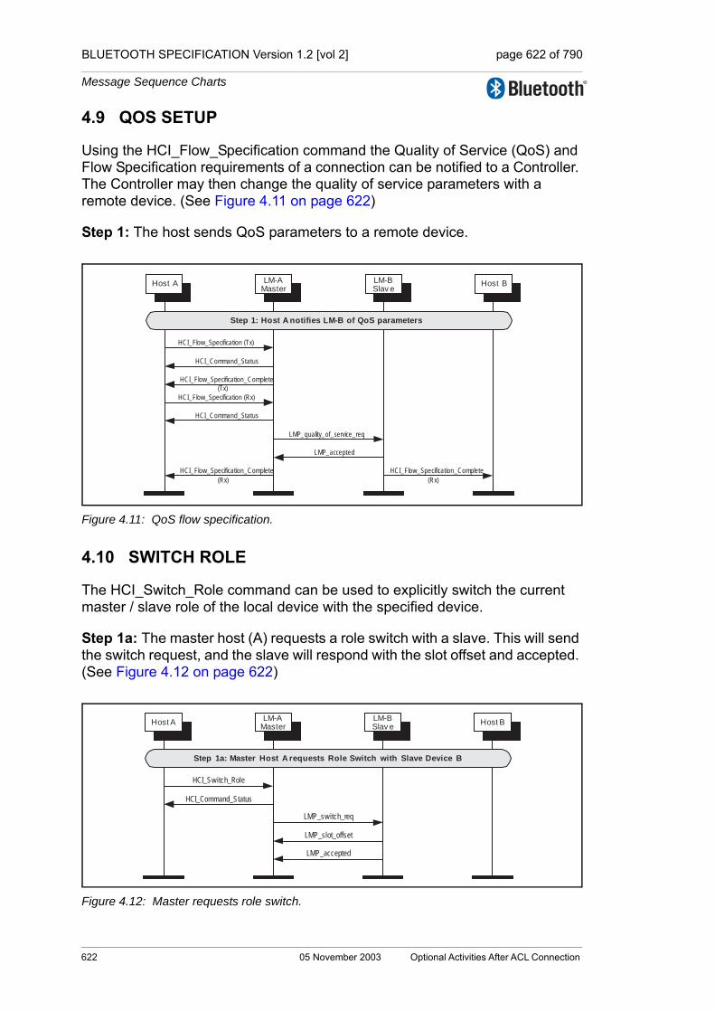
BLUETOOTH SPECIFICATION Version 1.2 [vol 2] page 622 of 790
Message Sequence Charts
4.9 QOS SETUP
Using the HCI_Flow_Specification command the Quality of Service (QoS) and Flow Specification requirements of a connection can be notified to a Controller. The Controller may then change the quality of service parameters with a remote device. (See Figure 4.11 on page 622)
Step 1: The host sends QoS parameters to a remote device.
Figure 4.11: QoS flow specification.
4.10 SWITCH ROLE
The HCI_Switch_Role command can be used to explicitly switch the current master / slave role of the local device with the specified device.
Step 1a: The master host (A) requests a role switch with a slave. This will send the switch request, and the slave will respond with the slot offset and accepted. (See Figure 4.12 on page 622)
Figure 4.12: Master requests role switch.
LM-AMaster
LM-BSlav e
Host A Host B
HCI_Flow_Specification (Tx)
Step 1: Host A notifies LM-B of QoS parameters
HCI_Flow_Specification_Complete
(Tx)
HCI_Command_Status
HCI_Flow_Specification (Rx)
HCI_Command_Status
LMP_accepted
LMP_quality_of_service_req
HCI_Flow_Specification_Complete
(Rx)
HCI_Flow_Specification_Complete
(Rx)
HCI_Switch_Role
LM-AMaster
LM-BSlav e
Host A Host B
HCI_Command_Status
LMP_switch_req
LMP_slot_offset
LMP_accepted
Step 1a: Master Host A requests Role Switch with Slave Device B
622 05 November 2003 Optional Activities After ACL Connection

BLUETOOTH SPECIFICATION Version 1.2 [vol 2] page 623 of 790
Message Sequence Charts
Step 1b: The slave host (B) requests a role switch with a master. This will send the slot offset and the switch request, and the master will respond with a LMP_accepted PDU. (See Figure 4.13 on page 623)
Figure 4.13: Slave requests role switch.
Step 2: The role switch is performed by doing the TDD switch and piconet switch. Finally an HCI_Role_Change event is sent on both sides. (See Figure 4.14 on page 623)
Figure 4.14: Role switch is performed.
LM-AMaster
LM-BSlav e
Host A Host B
LMP_switch_req
LMP_slot_of f set
LMP_accepted
HCI_Switch_Role
HCI_Command_Status
Step 1b: Slave Host B requests Role Switch with Master Device B
LM-AMaster
LM-BSlav e
Host A Host B
HCI_Role_Change (slave) HCI_Role_Change (master)
Role Switch performed using TDD
Switch
Step 2: Role Switch is performed
Piconet Switch
Optional Activities After ACL Connection Establishment05 November 2003 623

BLUETOOTH SPECIFICATION Version 1.2 [vol 2] page 624 of 790
Message Sequence Charts
624 05 November 2003 Optional Activities After ACL Connection

BLUETOOTH SPECIFICATION Version 1.2 [vol 2] page 625 of 790
Message Sequence Charts
5 SYNCHRONOUS CONNECTION ESTABLISHMENT AND DETACHMENT
5.1 SYNCHRONOUS CONNECTION SETUP
Using the HCI_Setup_Synchronous_Connection command, a host can add a synchronous logical channel to the link. A synchronous logical link can be pro-vided by creating a SCO or an eSCO logical transport.
Note: An ACL Connection must be established before a synchonous connec-tion can be created.
Step 1a: Master device requests a synchronous connection with a device. (See Figure 5.1 on page 625)
Figure 5.1: Master requests synchronous EV3, EV4 OR EV5 connection.
HCI_Setup_Synchronous_Connection
(EV3 | EV4 | EV5)
LM-AMaster
LM-BSlav e
Host A Host B
HCI_Command_Status
LMP_eSCO_link_req
HCI_Synchronous_Connection
_Complete (eSCO)
HCI_Connection_Request
(eSCO)
HCI_Accept_Synchronous
_Connection_Request
(EV3 | EV4 | EV5)
HCI_Command_Status
HCI_Synchronous_Connection
_Complete (eSCO)
LMP_eSCO_link_req
LMP_accepted_ex t
LMP_eSCO_link_req
Synchronous Connection started
Step 1a: Host A requests Synchronous Connection with Device B
Synchronous Connection Establishment and Detachment05 November 2003 625
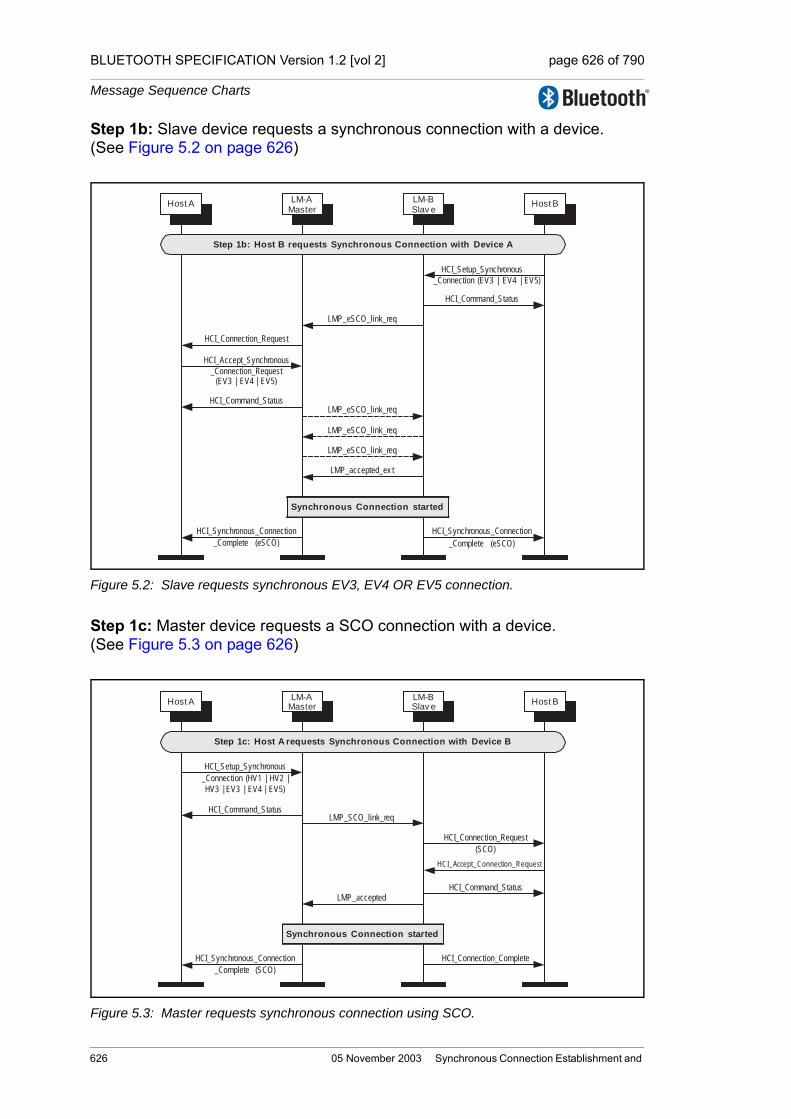
BLUETOOTH SPECIFICATION Version 1.2 [vol 2] page 626 of 790
Message Sequence Charts
Step 1b: Slave device requests a synchronous connection with a device. (See Figure 5.2 on page 626)
Figure 5.2: Slave requests synchronous EV3, EV4 OR EV5 connection.
Step 1c: Master device requests a SCO connection with a device. (See Figure 5.3 on page 626)
Figure 5.3: Master requests synchronous connection using SCO.
HCI_Setup_Synchronous
_Connection (EV3 | EV4 | EV5)
LM-AMaster
LM-BSlav e
Host A Host B
HCI_Command_Status
LMP_eSCO_link_req
HCI_Synchronous_Connection
_Complete (eSCO)
HCI_Connection_Request
HCI_Accept_Synchronous
_Connection_Request(EV3 | EV4 | EV5)
HCI_Command_Status
HCI_Synchronous_Connection
_Complete (eSCO)
LMP_eSCO_link_req
LMP_accepted_ex t
LMP_eSCO_link_req
LMP_eSCO_link_req
Synchronous Connection started
Step 1b: Host B requests Synchronous Connection with Device A
HCI_Setup_Synchronous
_Connection (HV1 | HV2 |
HV3 | EV3 | EV4 | EV5)
LM-AMaster
LM-BSlav e
Host A Host B
HCI_Command_Status
HCI_Synchronous_Connection
_Complete (SCO)
HCI_Connection_Request
(SCO)
HCI_Accept_Connection_Request
HCI_Command_Status
HCI_Connection_Complete
LMP_SCO_link_req
LMP_accepted
Synchronous Connection started
Step 1c: Host A requests Synchronous Connection with Device B
626 05 November 2003 Synchronous Connection Establishment and
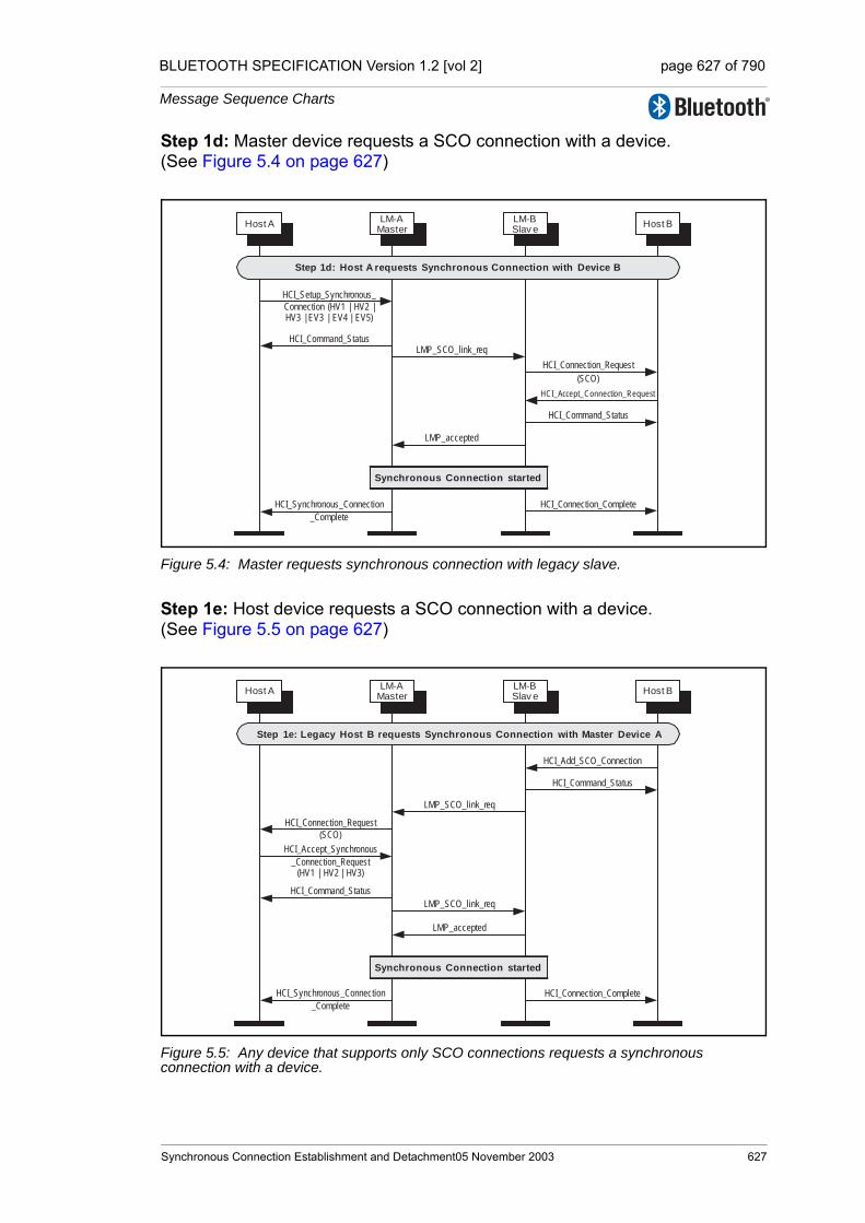
BLUETOOTH SPECIFICATION Version 1.2 [vol 2] page 627 of 790
Message Sequence Charts
Step 1d: Master device requests a SCO connection with a device. (See Figure 5.4 on page 627)
Figure 5.4: Master requests synchronous connection with legacy slave.
Step 1e: Host device requests a SCO connection with a device. (See Figure 5.5 on page 627)
Figure 5.5: Any device that supports only SCO connections requests a synchronous connection with a device.
HCI_Setup_Synchronous_
Connection (HV1 | HV2 |HV3 | EV3 | EV4 | EV5)
LM-AMaster
LM-BSlav e
Host A Host B
HCI_Command_Status
HCI_Synchronous_Connection
_Complete
HCI_Connection_Request
(SCO)
HCI_Accept_Connection_Request
HCI_Command_Status
HCI_Connection_Complete
LMP_SCO_link_req
LMP_accepted
Synchronous Connection started
Step 1d: Host A requests Synchronous Connection with Device B
HCI_Add_SCO_Connection
LM-AMaster
LM-BSlav e
Host A Host B
HCI_Command_Status
HCI_Synchronous_Connection
_Complete
HCI_Connection_Complete
LMP_SCO_link_req
LMP_accepted
Synchronous Connection started
HCI_Connection_Request
(SCO)
HCI_Accept_Synchronous
_Connection_Request(HV1 | HV2 | HV3)
HCI_Command_Status
LMP_SCO_link_req
Step 1e: Legacy Host B requests Synchronous Connection with Master Device A
Synchronous Connection Establishment and Detachment05 November 2003 627

BLUETOOTH SPECIFICATION Version 1.2 [vol 2] page 628 of 790
Message Sequence Charts
Step 2a: Master renegotiates eSCO connection (See Figure 5.6 on page 628).
Figure 5.6: Master renegotiates eSCO connection.
Step 2b: Slave renegotiates eSCO connection (See Figure 5.7 on page 628).
Figure 5.7: Slave renegotiates eSCO connection.
LM-AMaster
LM-BSlav e
Host A Host B
HCI_Command_Status
LMP_eSCO_link_req
LMP_accepted_ext
Synchronous Connectionchanged
Synchronous Connection existswith EV3, Tesco=6, and Wesco=4
HCI_Synchronous_Connection_Changed
HCI_Synchronous_Connection_Changed
HCI_Setup_Synchronous_Connection (Retransmission_effort = 0x00 )
LMP_eSCO_link_req
LMP_eSCO_link_req
Step 2a: Host-A changes Synchronous Connection with Device B
LM-AMaster
LM-BSlav eHost A Host B
HCI_Command_Status
LMP_eSCO_link_req
LMP_accepted_ext
Synchronous Connectionchanged
Synchronous Connection existswith EV3, Tesco=6, and Wesco=4
HCI_Synchronous_Connection_Changed
HCI_Synchronous_Connection_Changed
HCI_Setup_Synchronous_Connection(EV3, Retransmission_effort = 0x00)
LMP_eSCO_link_req
Step 2b: Host-B changes Synchronous Connection with Device A
628 05 November 2003 Synchronous Connection Establishment and
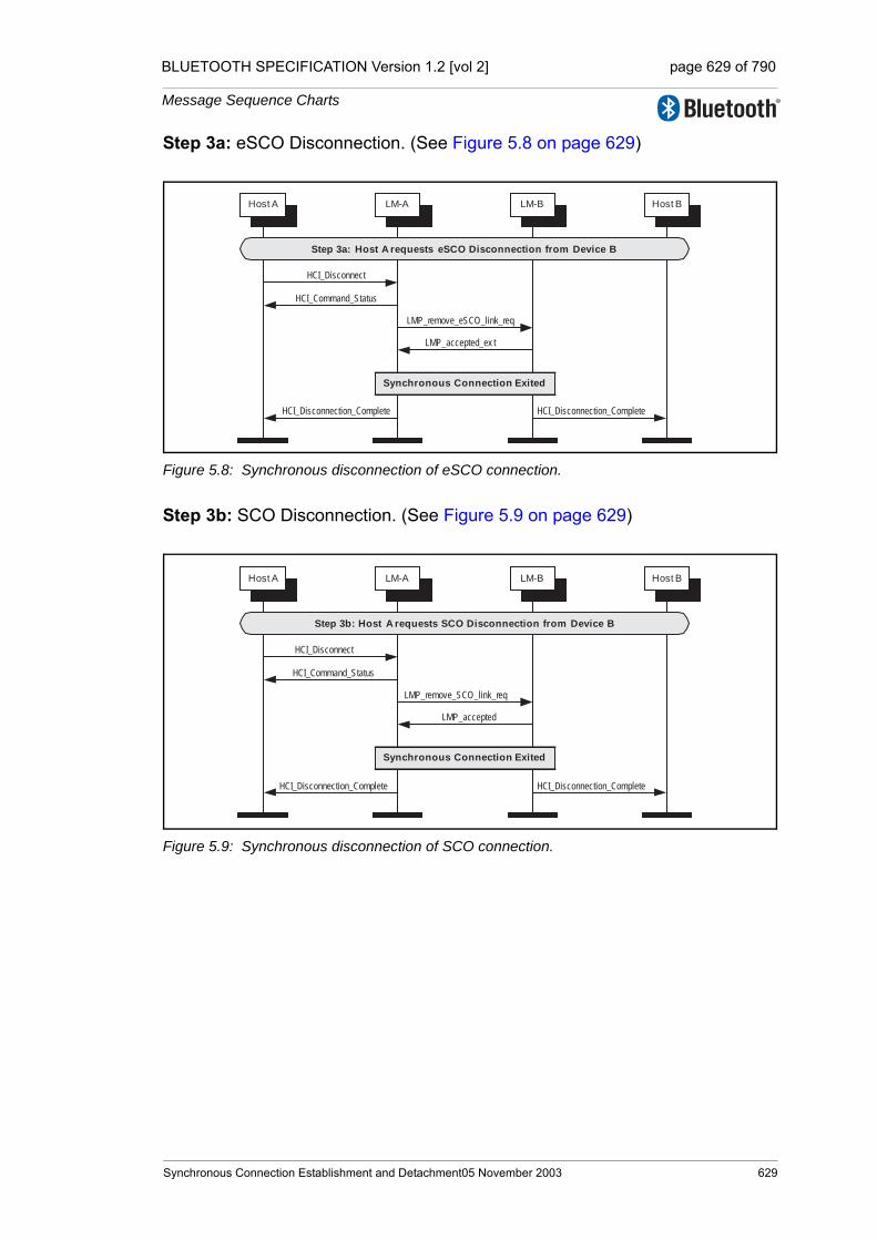
BLUETOOTH SPECIFICATION Version 1.2 [vol 2] page 629 of 790
Message Sequence Charts
Step 3a: eSCO Disconnection. (See Figure 5.8 on page 629)
Figure 5.8: Synchronous disconnection of eSCO connection.
Step 3b: SCO Disconnection. (See Figure 5.9 on page 629)
Figure 5.9: Synchronous disconnection of SCO connection.
HCI_Disconnect
LM-A LM-BHost A Host B
HCI_Command_Status
LMP_remove_eSCO_link_req
LMP_accepted_ex t
HCI_Disconnection_Complete HCI_Disconnection_Complete
Synchronous Connection Exited
Step 3a: Host A requests eSCO Disconnection from Device B
HCI_Disconnect
LM-A LM-BHost A Host B
HCI_Command_Status
LMP_remove_SCO_link_req
LMP_accepted
HCI_Disconnection_Complete HCI_Disconnection_Complete
Synchronous Connection Exited
Step 3b: Host A requests SCO Disconnection from Device B
Synchronous Connection Establishment and Detachment05 November 2003 629

BLUETOOTH SPECIFICATION Version 1.2 [vol 2] page 630 of 790
Message Sequence Charts
630 05 November 2003 Synchronous Connection Establishment and

BLUETOOTH SPECIFICATION Version 1.2 [vol 2] page 631 of 790
Message Sequence Charts
6 SNIFF, HOLD AND PARK
Entry into sniff mode, hold mode or park state requires an established ACL Connection.
6.1 SNIFF MODE
The HCI_Sniff_Mode command is used to enter sniff mode. The HCI_Exit_Sniff_Mode command is used to exit sniff mode.
Step 1: Host requests to enter sniff mode. Multiple LMP_sniff_req PDUs may be sent as the parameters for sniff mode are negotiated. (See Figure 6.1 on page 631)
Figure 6.1: Sniff mode request.
Step 2: Host requests to exit sniff mode. (See Figure 6.2 on page 631)
Figure 6.2: Exit sniff mode request.
HCI_Sniff_Mode
LM-A LM-BHost A Host B
HCI_Command_Status
LMP_sniff_req
LMP_accepted
HCI_Mode_Change (sniff) HCI_Mode_Change (sniff)
Sniff mode started
Step 1a: Host A requests Sniff Mode with Device B
HCI_Ex it_Sniff_Mode
LM-A LM-BHost A Host B
HCI_Command_Status
LMP_unsniff_req
HCI_Mode_Change (active) HCI_Mode_Change (active)
Sniff mode exited
LMP_accepted
Step 2: Host A exits Sniff Mode with Device B
Sniff, Hold and Park 05 November 2003 631

BLUETOOTH SPECIFICATION Version 1.2 [vol 2] page 632 of 790
Message Sequence Charts
6.2 HOLD MODE
The HCI_Hold_Mode command can be used to place a device into hold mode. The Controller may do this by either negotiating the hold mode parameters or forcing hold mode. Hold mode will automatically end after the negotiated length of time.
Step 1a: A host requests hold mode. (See Figure 6.3 on page 632)
Figure 6.3: Hold request.
Step 1b: A host may force hold mode. (See Figure 6.4 on page 632)
Figure 6.4: Master forces hold mode.
HCI_Hold_Mode
LM-A
Master
LM-B
Slav eHost A Host B
HCI_Command_Status
LMP_hold_req
LMP_accepted
HCI_Mode_Change (hold) HCI_Mode_Change (hold)
Hold mode started
LMP_set_AFH (AHS(79))
Step 1a: Host A requests Hold Mode with Device B
HCI_Hold_Mode
LM-A
Master
LM-B
Slav eHost A Host B
HCI_Command_Status
LMP_hold
HCI_Mode_Change (hold) HCI_Mode_Change (hold)
Hold mode started
LMP_set_AFH (AHS(79))
Step 1b: Master Host A forces Hold Mode with Slave Device B
632 05 November 2003 Sniff, Hold and Park
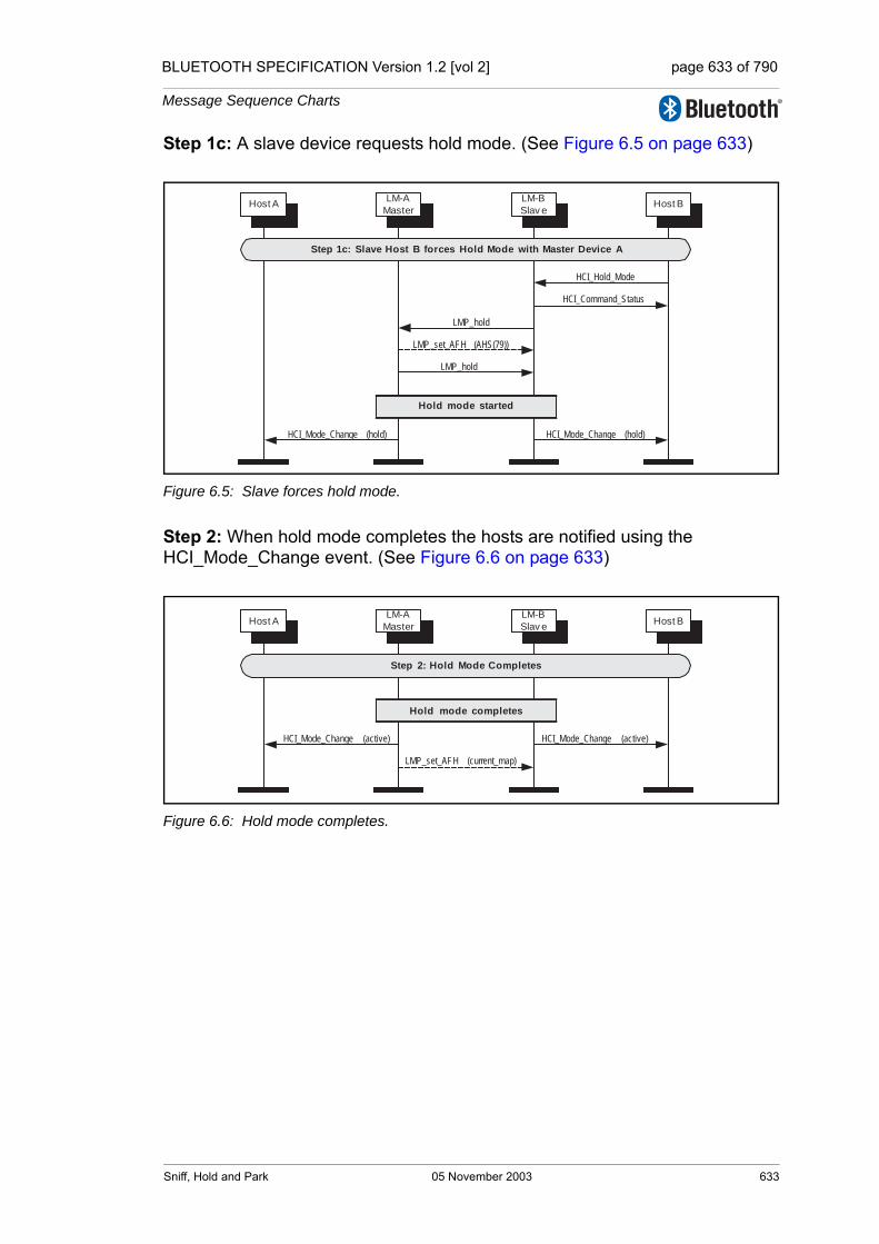
BLUETOOTH SPECIFICATION Version 1.2 [vol 2] page 633 of 790
Message Sequence Charts
Step 1c: A slave device requests hold mode. (See Figure 6.5 on page 633)
Figure 6.5: Slave forces hold mode.
Step 2: When hold mode completes the hosts are notified using the HCI_Mode_Change event. (See Figure 6.6 on page 633)
Figure 6.6: Hold mode completes.
HCI_Hold_Mode
LM-A
Master
LM-B
Slav eHost A Host B
HCI_Command_Status
LMP_hold
HCI_Mode_Change (hold) HCI_Mode_Change (hold)
Hold mode started
LMP_hold
LMP_set_AFH (AHS(79))
Step 1c: Slave Host B forces Hold Mode with Master Device A
LM-A
Master
LM-B
Slav eHost A Host B
HCI_Mode_Change (active) HCI_Mode_Change (active)
Hold mode completes
LMP_set_AFH (current_map)
Step 2: Hold Mode Completes
Sniff, Hold and Park 05 November 2003 633
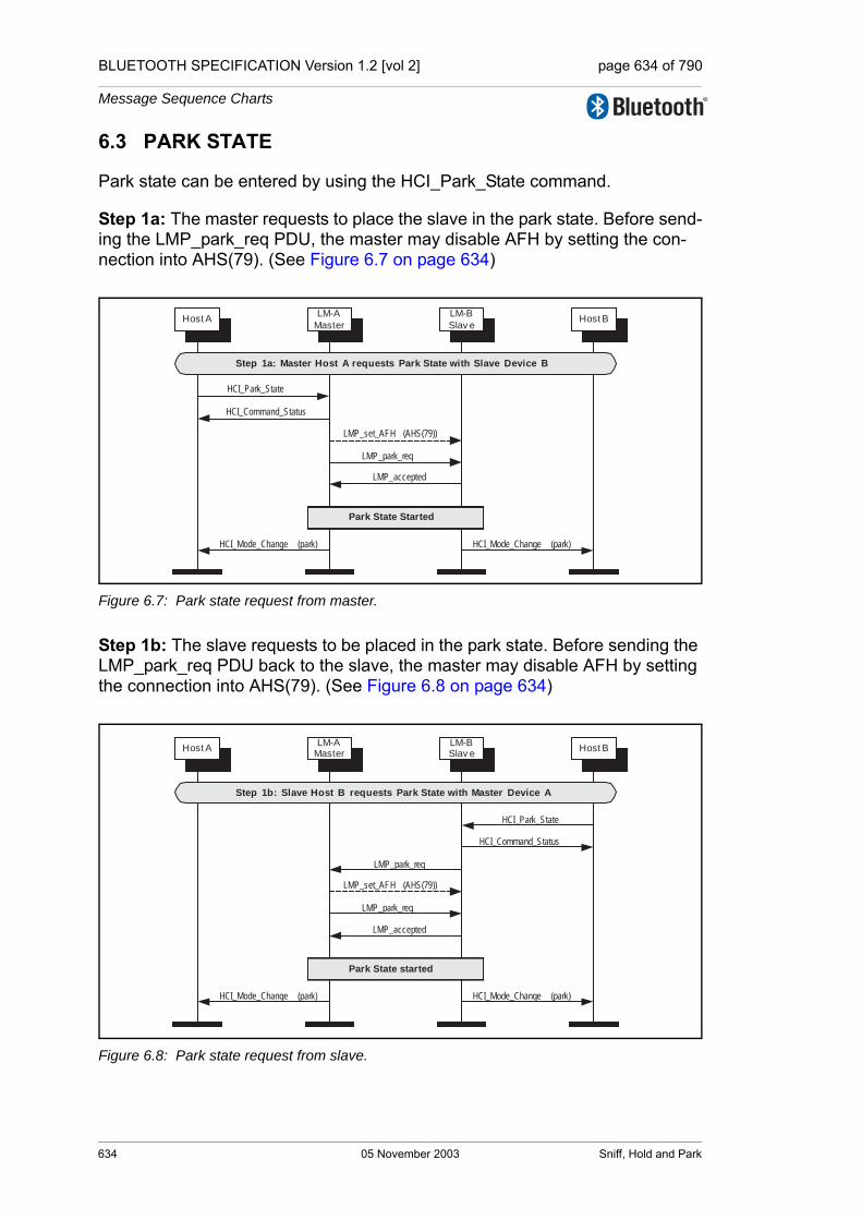
BLUETOOTH SPECIFICATION Version 1.2 [vol 2] page 634 of 790
Message Sequence Charts
6.3 PARK STATE
Park state can be entered by using the HCI_Park_State command.
Step 1a: The master requests to place the slave in the park state. Before send-ing the LMP_park_req PDU, the master may disable AFH by setting the con-nection into AHS(79). (See Figure 6.7 on page 634)
Figure 6.7: Park state request from master.
Step 1b: The slave requests to be placed in the park state. Before sending the LMP_park_req PDU back to the slave, the master may disable AFH by setting the connection into AHS(79). (See Figure 6.8 on page 634)
Figure 6.8: Park state request from slave.
HCI_Park_State
LM-A
Master
LM-B
Slav eHost A Host B
HCI_Command_Status
LMP_park_req
LMP_accepted
HCI_Mode_Change (park) HCI_Mode_Change (park)
Park State Started
LMP_set_AFH (AHS(79))
Step 1a: Master Host A requests Park State with Slave Device B
HCI_Park_State
LM-AMaster
LM-BSlav e
Host A Host B
HCI_Command_Status
LMP_park_req
HCI_Mode_Change (park) HCI_Mode_Change (park)
Park State started
LMP_set_AFH (AHS(79))
LMP_park_req
LMP_accepted
Step 1b: Slave Host B requests Park State with Master Device A
634 05 November 2003 Sniff, Hold and Park
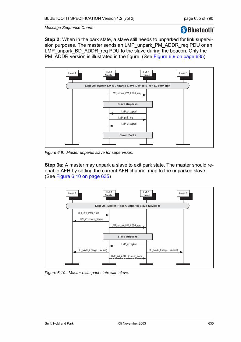
BLUETOOTH SPECIFICATION Version 1.2 [vol 2] page 635 of 790
Message Sequence Charts
Step 2: When in the park state, a slave still needs to unparked for link supervi-sion purposes. The master sends an LMP_unpark_PM_ADDR_req PDU or an LMP_unpark_BD_ADDR_req PDU to the slave during the beacon. Only the PM_ADDR version is illustrated in the figure. (See Figure 6.9 on page 635)
Figure 6.9: Master unparks slave for supervision.
Step 3a: A master may unpark a slave to exit park state. The master should re-enable AFH by setting the current AFH channel map to the unparked slave. (See Figure 6.10 on page 635)
Figure 6.10: Master exits park state with slave.
LM-AMaster
LM-BSlav e
Host A Host B
LMP_unpark_PM_ADDR_req
LMP_accepted
Slave Unparks
LMP_park_req
Slave Parks
LMP_accepted
Step 2a: Master LM-A unparks Slave Device B for Supervision
LM-AMaster
LM-BSlav e
Host A Host B
LMP_unpark_PM_ADDR_req
LMP_accepted
Slave Unparks
HCI_Ex it_Park_State
HCI_Command_Status
HCI_Mode_Change (active) HCI_Mode_Change (active)
LMP_set_AFH (current_map)
Step 2b: Master Host A unparks Slave Device B
Sniff, Hold and Park 05 November 2003 635

BLUETOOTH SPECIFICATION Version 1.2 [vol 2] page 636 of 790
Message Sequence Charts
Step 3b: A slave may unpark itself by sending a message in an access win-dow. It will then receive instructions from the master to unpark. The master should re-enable AFH by setting the current AFH channel map to the unparked slave. (See Figure 6.11 on page 636)
Figure 6.11: Slave exits park state with master.
LM-AMaster
LM-BSlav e
Host A Host B
Slave Unparks
HCI_Ex it_Park_State
HCI_Command_Status
HCI_Mode_Change (active) HCI_Mode_Change (active)
LMP_set_AFH (current_map)
Slave sends ID during Access
Window
LMP_unpark_PMADDR_req
LMP_accepted
Step 2c: Slave Host B Exits Park State with Master Device A
636 05 November 2003 Sniff, Hold and Park

BLUETOOTH SPECIFICATION Version 1.2 [vol 2] page 637 of 790
Message Sequence Charts
7 BUFFER MANAGEMENT, FLOW CONTROL
Buffer management is very important for resource limited devices. This can be achieved on the Host Controller Interface using the HCI_Read_Buffer_Size command, and the HCI_Number_Of_Completed_Packets event, and the HCI_Set_Host_Controller_To_Host_Flow_Control, HCI_Host_Buffer_Size and HCI_Host_Number_Of_Completed_Packets commands.
Step 1: During initialization, the host reads the buffer sizes available in the Controller. When an HCI Data Packet has been transferred to the remote device, and a Baseband acknowledgement has been received for this data, then an HCI_Number_Of_Completed_Packets event will be generated. (See Figure 7.1 on page 637)
Figure 7.1: Host to Controller flow control.
HCI_Read_Buffer_Size
Host A Host B
HCI_Command_Complete
Data Packet
HCI_Number_Of_
Completed_Packets
After an ACL connection is established
ACL Data Packet
BB ACK
ACL Data Packet
Step 1: Host A Initializes and uses Flow Control
LM-A⇒BB-A LM-B⇒BB-B
Buffer Management, Flow Control 05 November 2003 637
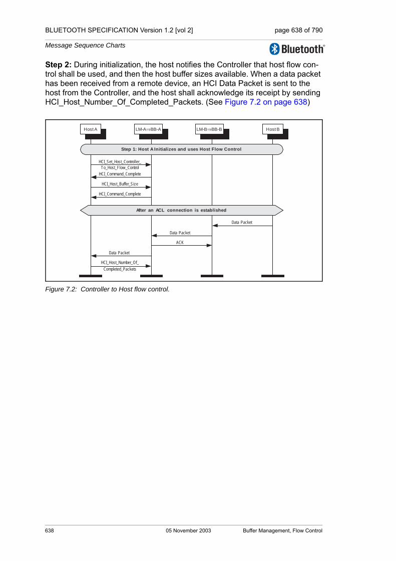
BLUETOOTH SPECIFICATION Version 1.2 [vol 2] page 638 of 790
Message Sequence Charts
Step 2: During initialization, the host notifies the Controller that host flow con-trol shall be used, and then the host buffer sizes available. When a data packet has been received from a remote device, an HCI Data Packet is sent to the host from the Controller, and the host shall acknowledge its receipt by sending HCI_Host_Number_Of_Completed_Packets. (See Figure 7.2 on page 638)
Figure 7.2: Controller to Host flow control.
HCI_Set_Host_Controller_
To_Host_Flow_Control
Host A Host B
HCI_Command_Complete
Data Packet
After an ACL connection is established
ACK
Data Packet
HCI_Host_Buffer_Size
HCI_Command_Complete
Data Packet
HCI_Host_Number_Of_
Completed_Packets
Step 1: Host A Initializes and uses Host Flow Control
LM-A⇒BB-A LM-B⇒BB-B
638 05 November 2003 Buffer Management, Flow Control

BLUETOOTH SPECIFICATION Version 1.2 [vol 2] page 639 of 790
Message Sequence Charts
8 LOOPBACK MODE
The loopback modes are used for testing of a device only.
8.1 LOCAL LOOPBACK MODE
The local loopback mode is used to loopback received HCI Commands, and HCI ACL and HCI Synchronous packets sent from the Host to the Controller.
Step 1: The host enters local loopback mode. Four connection complete events are generated and then a command complete event. (See Figure 8.1 on page 639)
Figure 8.1: Entering local loopback mode.
Step 2a: The host sending HCI Data Packet will receive the exact same data back in HCI Data Packets from the Controller. (See Figure 8.2 on page 639)
Figure 8.2: Looping back data in local loopback mode.
HCI_Write_Loopback_Mode
(local)
Host A Host B
HCI_Command_Complete
HCI_Connection_Complete
(ACL)HCI_Connection_Complete
(SCO or eSCO) HCI_Connection_Complete
(SCO or eSCO)
HCI_Connection_Complete
(SCO or eSCO)
Step 1: Host enters Local Loopback Mode
LM-A⇒BB-A LM-B⇒BB-B
Host A Host B
ACL Data Packet
ACL Data Packet
ACL Data Packet
ACL Data Packet
Step 2a: Host enters sends data to Controller while in Local Loopback Mode
LM-A⇒BB-A LM-B⇒BB-B
Loopback Mode 05 November 2003 639

BLUETOOTH SPECIFICATION Version 1.2 [vol 2] page 640 of 790
Message Sequence Charts
Step 2b: The host sending most HCI Command Packets to the Controller will receive an HCI_Loopback_Command event with the contents of the HCI Com-mand Packet in the payload. (See Figure 8.3 on page 640)
Figure 8.3: Looping back commands in local loopback mode.
Step 3: The host exits local loopback mode. Multiple disconnection complete events are generated before the command complete event. (See Figure 8.4 on page 640)
Figure 8.4: Exiting local loopback mode.
Host A Host B
HCI Command Packet
HCI_Loopback_Command
HCI Command Packet
HCI_Loopback_Command
Step 2b: Host enters sends HCI Commands to Controller while in Local Loopback
Mode
LM-A⇒BB-A LM-B⇒BB-B
HCI_Write_Loopback_Mode
(no loopback)
HCI_Command_Complete
HCI_Disconnection_Complete
(ACL)
HCI_Disconnection_Complete
(SCO or eSCO)
HCI_Disconnection_Complete
(SCO or eSCO)HCI_Disconnection_Complete
(SCO or eSCO))
Host A Host B
Step 2: Host Exits Local Loopback Mode
LM-A⇒BB-A LM-B⇒BB-B
640 05 November 2003 Loopback Mode

BLUETOOTH SPECIFICATION Version 1.2 [vol 2] page 641 of 790
Message Sequence Charts
8.2 REMOTE LOOPBACK MODE
The remote loopback mode is used to lookback data to a remote device over the air.
Step 1: The remote host first sets up an connection to the local device. The local device then enables remote loopback. (See Figure 8.5 on page 641)
Figure 8.5: Entering remote loopback mode.
Step 2: Any data received from the remote host will be loopbacked in the Con-troller of the local device. (See Figure 8.6 on page 641)
Figure 8.6: Looping back data in Remote Loopback Mode.
HCI_Write_Loopback_Mode
(remote)
Host A Host B
HCI_Command_Complete
Host B creates ACL Connection
Step 1: Hosts enters Remote Loopback Mode
LM-A⇒BB-A LM-B⇒BB-B
HCI Data Packet
Data Packet
Data Packet
HCI Data Packet
ACK
HCI_Number_Of_Completed
_Packets
Host A Host B
Step 2: Host B sends data packets that will loopback through Device A
LM-A⇒BB-A LM-B⇒BB-B
Loopback Mode 05 November 2003 641
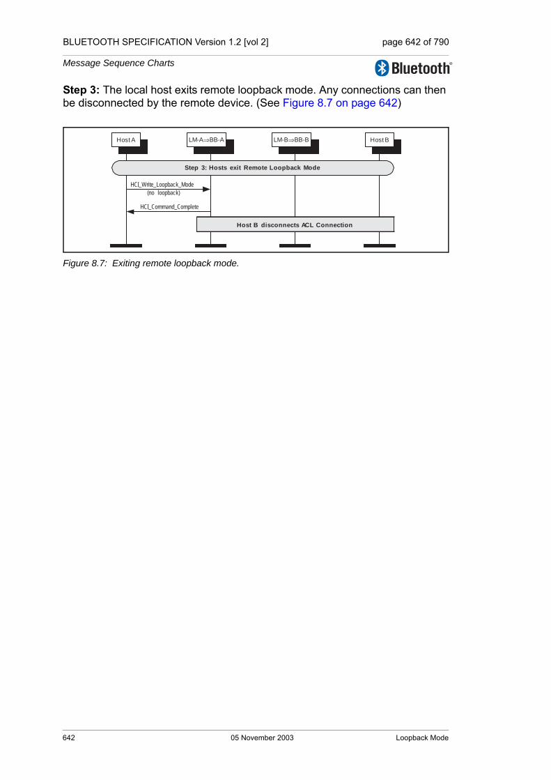
BLUETOOTH SPECIFICATION Version 1.2 [vol 2] page 642 of 790
Message Sequence Charts
Step 3: The local host exits remote loopback mode. Any connections can then be disconnected by the remote device. (See Figure 8.7 on page 642)
Figure 8.7: Exiting remote loopback mode.
HCI_Write_Loopback_Mode
(no loopback)
Host A Host B
HCI_Command_Complete
Host B disconnects ACL Connection
Step 3: Hosts exit Remote Loopback Mode
LM-A⇒BB-A LM-B⇒BB-B
642 05 November 2003 Loopback Mode

BLUETOOTH SPECIFICATION Version 1.2 [vol 2] page 643 of 790
Message Sequence Charts
9 LIST OF FIGURES
Figure 1.1: Example MSC. ........................................................................600
Figure 2.1: Remote name request. ............................................................601Figure 2.2: Remote name request if no current baseband connection. ....601Figure 2.3: Remote name request with baseband connection. .................602Figure 2.4: Host A starts inquiry procedure. ..............................................602Figure 2.5: LM-A performs inquiry and reports result.. ..............................603Figure 2.6: Host A cancels inquiry. ............................................................603Figure 2.7: LM-A terminates current inquiry. .............................................604Figure 2.8: Host A starts periodic inquiry. ..................................................604Figure 2.9: LM-A periodically performs an inquiry and reports result. .......605Figure 2.10: LM-A terminates current inquiry. .............................................605Figure 2.11: Host A decides to exit periodic inquiry. ...................................605
Figure 3.1: Overview diagram for connection setup. .................................607Figure 3.2: Host A requests connection with device B. .............................608Figure 3.3: LM-A and LM-B exchange features. .......................................608Figure 3.4: LM-A requests host connection. ..............................................608Figure 3.5: Device B rejects connection request. ......................................609Figure 3.6: Device B accepts connection request. ....................................609Figure 3.7: Device B accepts connection requests as master. ..................610Figure 3.8: LM-A starts adaptive frequency hopping. ................................610Figure 3.9: Authentication initiated. ...........................................................611Figure 3.10: Pairing during connection setup. .............................................612Figure 3.11: Authentication during connection setup. .................................613Figure 3.12: Starting encryption during connection setup. ..........................613Figure 3.13: LM-A and LM-B finishes connection setup. .............................614Figure 3.14: Host A decides to disconnect. .................................................614
Figure 4.1: Authentication requested. .......................................................615Figure 4.2: Encryption requested. .............................................................616Figure 4.3: Encryption off requested. ........................................................616Figure 4.4: Change connection link key. ...................................................617Figure 4.5: Change to master link key. ......................................................618Figure 4.6: Change to semi permanent link key. .......................................619Figure 4.7: Read remote supported features. ...........................................620Figure 4.8: Read remote extended features. .............................................620Figure 4.9: Read clock offset. ....................................................................621Figure 4.10: Read remote version information. ...........................................621Figure 4.11: QoS flow specification. ............................................................622
List of Figures 05 November 2003 643
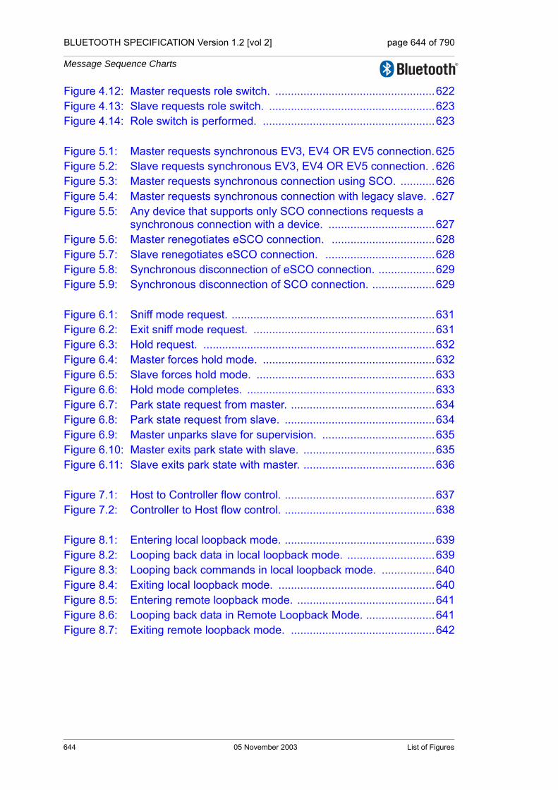
BLUETOOTH SPECIFICATION Version 1.2 [vol 2] page 644 of 790
Message Sequence Charts
Figure 4.12: Master requests role switch. ...................................................622Figure 4.13: Slave requests role switch. .....................................................623Figure 4.14: Role switch is performed. .......................................................623
Figure 5.1: Master requests synchronous EV3, EV4 OR EV5 connection.625Figure 5.2: Slave requests synchronous EV3, EV4 OR EV5 connection. .626Figure 5.3: Master requests synchronous connection using SCO. ...........626Figure 5.4: Master requests synchronous connection with legacy slave. .627Figure 5.5: Any device that supports only SCO connections requests a
synchronous connection with a device. ..................................627Figure 5.6: Master renegotiates eSCO connection. .................................628Figure 5.7: Slave renegotiates eSCO connection. ...................................628Figure 5.8: Synchronous disconnection of eSCO connection. ..................629Figure 5.9: Synchronous disconnection of SCO connection. ....................629
Figure 6.1: Sniff mode request. .................................................................631Figure 6.2: Exit sniff mode request. ..........................................................631Figure 6.3: Hold request. ..........................................................................632Figure 6.4: Master forces hold mode. .......................................................632Figure 6.5: Slave forces hold mode. .........................................................633Figure 6.6: Hold mode completes. ............................................................633Figure 6.7: Park state request from master. ..............................................634Figure 6.8: Park state request from slave. ................................................634Figure 6.9: Master unparks slave for supervision. ....................................635Figure 6.10: Master exits park state with slave. ..........................................635Figure 6.11: Slave exits park state with master. ..........................................636
Figure 7.1: Host to Controller flow control. ................................................637Figure 7.2: Controller to Host flow control. ................................................638
Figure 8.1: Entering local loopback mode. ................................................639Figure 8.2: Looping back data in local loopback mode. ............................639Figure 8.3: Looping back commands in local loopback mode. .................640Figure 8.4: Exiting local loopback mode. ..................................................640Figure 8.5: Entering remote loopback mode. ............................................641Figure 8.6: Looping back data in Remote Loopback Mode. ......................641Figure 8.7: Exiting remote loopback mode. ..............................................642
644 05 November 2003 List of Figures

Core System Package [Controller volume]
Part GSAMPLE DATA
This appendix contains sample data for various parts of the Bluetooth baseband specification. All sample data are provided for reference purpose only; they are intended as a complement to the definitions provided elsewhere in the specification. They can be used to check the behavior of an implementation and avoid misunderstandings. Fulfilling these sample data is a necessary but not sufficient condition for an implementation to be fully Bluetooth compliant.

BLUETOOTH SPECIFICATION Version 1.2 [vol 2] page 646 of 790
Sample Data
646 05 November 2003

BLUETOOTH SPECIFICATION Version 1.2 [vol 2] page 647 of 790
Sample Data
CONTENTS
1 Encryption Sample Data ..................................................................6491.1 Generating Kc' from Kc, ...........................................................6491.2 First Set of Sample Data ..........................................................6521.3 Second Set of Sample Data.....................................................6601.4 Third Set of Samples................................................................6681.5 Fourth Set of Samples .............................................................676
2 Frequency Hopping Sample Data ...................................................6852.1 First set ....................................................................................6862.2 Second set ...............................................................................6922.3 Third set ...................................................................................698
3 Access Code Sample Data ..............................................................7054 HEC and Packet Header Sample Data ............................................7095 CRC Sample Data .............................................................................7116 Complete Sample Packets...............................................................713
6.1 Example of DH1 Packet ...........................................................7136.2 Example of DM1 Packet...........................................................714
7 Whitening Sequence Sample Data .................................................7158 FEC Sample Data..............................................................................7199 Encryption Key Sample Data ..........................................................721
9.1 Four Tests of E1 .......................................................................7219.2 Four Tests of E21 .....................................................................7269.3 Three Tests of E22 ...................................................................7289.4 Tests of E22 With Pin Augmenting...........................................7309.5 Four Tests of E3 .......................................................................740
05 November 2003 647

BLUETOOTH SPECIFICATION Version 1.2 [vol 2] page 648 of 790
Sample Data
648 05 November 2003

BLUETOOTH SPECIFICATION Version 1.2 [vol 2] page 649 of 790
Sample Data
1 ENCRYPTION SAMPLE DATA
This section contains four sets of sample data for the encryption process.
With respect to the functional description of the encryption engine in the Blue-tooth baseband specification, the contents of registers and resulting concurrent values are listed as well. This by no means excludes different implementations (as far as they produce the same encryption stream) but is intended to describe the functional behavior.
In case of misunderstandings or inconsistencies, these sample data form the normative reference.
1.1 GENERATING KC' FROM KC,
where Kc'(x) = g2(x)(Kc(x) mod g1(x)).
Note: All polynomials are in hexadecimal notation.
'L' is the effective key length in bytes.
The notation 'p: [m]' implies that deg(p(x)) = m.
MSB LSB
L = 1
g1: [8] 00000000 00000000 00000000 0000011d
g2: [119] 00e275a0 abd218d4 cf928b9b bf6cb08f
Kc: a2b230a4 93f281bb 61a85b82 a9d4a30e
Kc mod g1: [7] 00000000 00000000 00000000 0000009f
g2(Kc mod g1): [126] 7aa16f39 59836ba3 22049a7b 87f1d8a5
-----------------------------------------------------------
L = 2
g1: [16] 00000000 00000000 00000000 0001003f
g2: [112] 0001e3f6 3d7659b3 7f18c258 cff6efef
Kc: 64e7df78 bb7ccaa4 61433123 5b3222ad
Kc mod g1: [12] 00000000 00000000 00000000 00001ff0
g2(Kc mod g1): [124] 142057bb 0bceac4c 58bd142e 1e710a50
-----------------------------------------------------------
L = 3
g1: [24] 00000000 00000000 00000000 010000db
g2: [104] 000001be f66c6c3a b1030a5a 1919808b
Kc: 575e5156 ba685dc6 112124ac edb2c179
Kc mod g1: [23] 00000000 00000000 00000000 008ddbc8
g2(Kc mod g1): [127] d56d0adb 8216cb39 7fe3c591 1ff95618
-----------------------------------------------------------
L = 4
g1: [32] 00000000 00000000 00000001 000000af
g2: [96] 00000001 6ab89969 de17467f d3736ad9
Kc: 8917b4fc 403b6db2 1596b86d 1cb8adab
Kc mod g1: [31] 00000000 00000000 00000000 aa1e78aa
g2(Kc mod g1): [127] 91910128 b0e2f5ed a132a03e af3d8cda
-----------------------------------------------------------
Encryption Sample Data 05 November 2003 649
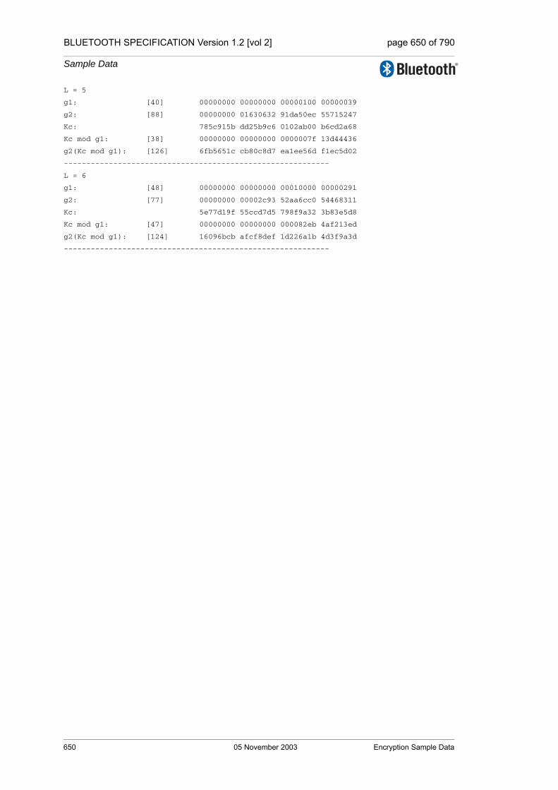
BLUETOOTH SPECIFICATION Version 1.2 [vol 2] page 650 of 790
Sample Data
L = 5
g1: [40] 00000000 00000000 00000100 00000039
g2: [88] 00000000 01630632 91da50ec 55715247
Kc: 785c915b dd25b9c6 0102ab00 b6cd2a68
Kc mod g1: [38] 00000000 00000000 0000007f 13d44436
g2(Kc mod g1): [126] 6fb5651c cb80c8d7 ea1ee56d f1ec5d02
-----------------------------------------------------------
L = 6
g1: [48] 00000000 00000000 00010000 00000291
g2: [77] 00000000 00002c93 52aa6cc0 54468311
Kc: 5e77d19f 55ccd7d5 798f9a32 3b83e5d8
Kc mod g1: [47] 00000000 00000000 000082eb 4af213ed
g2(Kc mod g1): [124] 16096bcb afcf8def 1d226a1b 4d3f9a3d
-----------------------------------------------------------
650 05 November 2003 Encryption Sample Data

BLUETOOTH SPECIFICATION Version 1.2 [vol 2] page 651 of 790
Sample Data
L = 7
g1: [56] 00000000 00000000 01000000 00000095
g2: [71] 00000000 000000b3 f7fffce2 79f3a073
Kc: 05454e03 8ddcfbe3 ed024b2d 92b7f54c
Kc mod g1: [55] 00000000 00000000 0095b8a4 8eb816da
g2(Kc mod g1): [126] 50f9c0d4 e3178da9 4a09fe0d 34f67b0e
-----------------------------------------------------------
L = 8
g1: [64] 00000000 00000001 00000000 0000001b
g2: [63] 00000000 00000000 a1ab815b c7ec8025
Kc: 7ce149fc f4b38ad7 2a5d8a41 eb15ba31
Kc mod g1: [63] 00000000 00000000 8660806c 1865deec
g2(Kc mod g1): [126] 532c36d4 5d0954e0 922989b6 826f78dc
-----------------------------------------------------------
L = 9
g1: [72] 00000000 00000100 00000000 00000609
g2: [49] 00000000 00000000 0002c980 11d8b04d
Kc: 5eeff7ca 84fc2782 9c051726 3df6f36e
Kc mod g1: [71] 00000000 00000083 58ccb7d0 b95d3c71
g2(Kc mod g1): [120] 016313f6 0d3771cf 7f8e4bb9 4aa6827d
-----------------------------------------------------------
L = 10
g1: [80] 00000000 00010000 00000000 00000215
g2: [42] 00000000 00000000 0000058e 24f9a4bb
Kc: 7b13846e 88beb4de 34e7160a fd44dc65
Kc mod g1: [79] 00000000 0000b4de 34171767 f36981c3
g2(Kc mod g1): [121] 023bc1ec 34a0029e f798dcfb 618ba58d
-----------------------------------------------------------
L = 11
g1: [88] 00000000 01000000 00000000 0000013b
g2: [35] 00000000 00000000 0000000c a76024d7
Kc: bda6de6c 6e7d757e 8dfe2d49 9a181193
Kc mod g1: [86] 00000000 007d757e 8dfe88aa 2fcee371
g2(Kc mod g1): [121] 022e08a9 3aa51d8d 2f93fa78 85cc1f87
-----------------------------------------------------------
L = 12
g1: [96] 00000001 00000000 00000000 000000dd
g2: [28] 00000000 00000000 00000000 1c9c26b9
Kc: e6483b1c 2cdb1040 9a658f97 c4efd90d
Kc mod g1: [93] 00000000 2cdb1040 9a658fd7 5b562e41
g2(Kc mod g1): [121] 030d752b 216fe29b b880275c d7e6f6f9
-----------------------------------------------------------
L = 13
g1: [104] 00000100 00000000 00000000 0000049d
g2: [21] 00000000 00000000 00000000 0026d9e3
Kc: d79d281d a2266847 6b223c46 dc0ab9ee
Kc mod g1: [100] 0000001d a2266847 6b223c45 e1fc5fa6
g2(Kc mod g1): [121] 03f11138 9cebf919 00b93808 4ac158aa
-----------------------------------------------------------
Encryption Sample Data 05 November 2003 651

BLUETOOTH SPECIFICATION Version 1.2 [vol 2] page 652 of 790
Sample Data
L = 14
g1: [112] 00010000 00000000 00000000 0000014f
g2: [14] 00000000 00000000 00000000 00004377
Kc: cad9a65b 9fca1c1d a2320fcf 7c4ae48e
Kc mod g1: [111] 0000a65b 9fca1c1d a2320fcf 7cb6a909
g2(Kc mod g1): [125] 284840fd f1305f3c 529f5703 76adf7cf
-----------------------------------------------------------
L = 15
g1: [120] 01000000 00000000 00000000 000000e7
g2: [7] 00000000 00000000 00000000 00000089
Kc: 21f0cc31 049b7163 d375e9e1 06029809
Kc mod g1: [119] 00f0cc31 049b7163 d375e9e1 0602840e
g2(Kc mod g1): [126] 7f10b53b 6df84b94 f22e566a 3754a37e
-----------------------------------------------------------
L = 16
g1: [128] 00000001 00000000 00000000 00000000 00000000
g2: [0] 00000000 00000000 00000000 00000001
Kc: 35ec8fc3 d50ccd32 5f2fd907 bde206de
Kc mod g1: [125] 35ec8fc3 d50ccd32 5f2fd907 bde206de
g2(Kc mod g1): [125] 35ec8fc3 d50ccd32 5f2fd907 bde206de
-----------------------------------------------------------
1.2 FIRST SET OF SAMPLE DATA
Initial values for the key, pan address and clock
K’c1[0] = 00 K’c1[1] = 00 K’c1[2] = 00 K’c1[3] = 00
K’c1[4] = 00 K’c1[5] = 00 K’c1[6] = 00 K’c1[7] = 00
K’c1[8] = 00 K’c1[9] = 00 K’c1[10] = 00 K’c1[11] = 00
K’c1[12] = 00 K’c1[13] = 00 K’c1[14] = 00 K’c1[15] = 00
Addr1[0] = 00 Addr1[1] = 00 Addr1[2] = 00
Addr1[3] = 00 Addr1[4] = 00 Addr1[5] = 00
CL1[0] = 00 CL1[1] = 00 CL1[2] = 00 CL1[3] = 00
===============================================================================================
Fill LFSRs with initial data
===============================================================================================
t clk# LFSR1 LFSR2 LFSR3 LFSR4 X1 X2 X3 X4 Z C[t+1] C[t] C[t-1]
0 0 0000000* 00000000* 000000000* 0000000000* 0 0 0 0 0 00 00 00
1 1 0000000* 00000001* 000000000* 0000000001* 0 0 0 0 0 00 00 00
2 2 0000000* 00000002* 000000000* 0000000003* 0 0 0 0 0 00 00 00
3 3 0000000* 00000004* 000000000* 0000000007* 0 0 0 0 0 00 00 00
4 4 0000000* 00000008* 000000000* 000000000E* 0 0 0 0 0 00 00 00
5 5 0000000* 00000010* 000000000* 000000001C* 0 0 0 0 0 00 00 00
6 6 0000000* 00000020* 000000000* 0000000038* 0 0 0 0 0 00 00 00
652 05 November 2003 Encryption Sample Data

BLUETOOTH SPECIFICATION Version 1.2 [vol 2] page 653 of 790
Sample Data
7 7 0000000* 00000040* 000000000* 0000000070* 0 0 0 0 0 00 00 00
8 8 0000000* 00000080* 000000000* 00000000E0* 0 0 0 0 0 00 00 00
9 9 0000000* 00000100* 000000000* 00000001C0* 0 0 0 0 0 00 00 00
10 10 0000000* 00000200* 000000000* 0000000380* 0 0 0 0 0 00 00 00
11 11 0000000* 00000400* 000000000* 0000000700* 0 0 0 0 0 00 00 00
12 12 0000000* 00000800* 000000000* 0000000E00* 0 0 0 0 0 00 00 00
13 13 0000000* 00001000* 000000000* 0000001C00* 0 0 0 0 0 00 00 00
14 14 0000000* 00002000* 000000000* 0000003800* 0 0 0 0 0 00 00 00
15 15 0000000* 00004000* 000000000* 0000007000* 0 0 0 0 0 00 00 00
16 16 0000000* 00008000* 000000000* 000000E000* 0 0 0 0 0 00 00 00
17 17 0000000* 00010000* 000000000* 000001C000* 0 0 0 0 0 00 00 00
18 18 0000000* 00020000* 000000000* 0000038000* 0 0 0 0 0 00 00 00
19 19 0000000* 00040000* 000000000* 0000070000* 0 0 0 0 0 00 00 00
20 20 0000000* 00080000* 000000000* 00000E0000* 0 0 0 0 0 00 00 00
21 21 0000000* 00100000* 000000000* 00001C0000* 0 0 0 0 0 00 00 00
22 22 0000000* 00200000* 000000000* 0000380000* 0 0 0 0 0 00 00 00
23 23 0000000* 00400000* 000000000* 0000700000* 0 0 0 0 0 00 00 00
24 24 0000000* 00800000* 000000000* 0000E00000* 0 1 0 0 1 00 00 00
25 25 0000000* 01000000* 000000000* 0001C00000* 0 0 0 0 0 00 00 00
26 26 0000000 02000000* 000000000* 0003800000* 0 0 0 0 0 00 00 00
27 27 0000000 04000000* 000000000* 0007000000* 0 0 0 0 0 00 00 00
28 28 0000000 08000000* 000000000* 000E000000* 0 0 0 0 0 00 00 00
29 29 0000000 10000000* 000000000* 001C000000* 0 0 0 0 0 00 00 00
30 30 0000000 20000000* 000000000* 0038000000* 0 0 0 0 0 00 00 00
31 31 0000000 40000000* 000000000* 0070000000* 0 0 0 0 0 00 00 00
32 32 0000000 00000001 000000000* 00E0000000* 0 0 0 1 1 00 00 00
33 33 0000000 00000002 000000000* 01C0000000* 0 0 0 1 1 00 00 00
34 34 0000000 00000004 000000000 0380000000* 0 0 0 1 1 00 00 00
35 35 0000000 00000008 000000000 0700000000* 0 0 0 0 0 00 00 00
36 36 0000000 00000010 000000000 0E00000000* 0 0 0 0 0 00 00 00
37 37 0000000 00000020 000000000 1C00000000* 0 0 0 0 0 00 00 00
38 38 0000000 00000040 000000000 3800000000* 0 0 0 0 0 00 00 00
39 39 0000000 00000080 000000000 7000000000* 0 0 0 0 0 00 00 00
===============================================================================================
Start clocking Summation Combiner
===============================================================================================
40 1 0000000 00000100 000000000 6000000001 0 0 0 0 0 00 00 00
41 2 0000000 00000200 000000000 4000000003 0 0 0 0 0 00 00 00
42 3 0000000 00000400 000000000 0000000007 0 0 0 0 0 00 00 00
43 4 0000000 00000800 000000000 000000000E 0 0 0 0 0 00 00 00
44 5 0000000 00001001 000000000 000000001D 0 0 0 0 0 00 00 00
45 6 0000000 00002002 000000000 000000003B 0 0 0 0 0 00 00 00
46 7 0000000 00004004 000000000 0000000077 0 0 0 0 0 00 00 00
47 8 0000000 00008008 000000000 00000000EE 0 0 0 0 0 00 00 00
48 9 0000000 00010011 000000000 00000001DD 0 0 0 0 0 00 00 00
49 10 0000000 00020022 000000000 00000003BB 0 0 0 0 0 00 00 00
50 11 0000000 00040044 000000000 0000000777 0 0 0 0 0 00 00 00
51 12 0000000 00080088 000000000 0000000EEE 0 0 0 0 0 00 00 00
52 13 0000000 00100110 000000000 0000001DDD 0 0 0 0 0 00 00 00
53 14 0000000 00200220 000000000 0000003BBB 0 0 0 0 0 00 00 00
54 15 0000000 00400440 000000000 0000007777 0 0 0 0 0 00 00 00
55 16 0000000 00800880 000000000 000000EEEE 0 1 0 0 1 00 00 00
56 17 0000000 01001100 000000000 000001DDDD 0 0 0 0 0 00 00 00
57 18 0000000 02002200 000000000 000003BBBB 0 0 0 0 0 00 00 00
58 19 0000000 04004400 000000000 0000077777 0 0 0 0 0 00 00 00
59 20 0000000 08008800 000000000 00000EEEEE 0 0 0 0 0 00 00 00
60 21 0000000 10011000 000000000 00001DDDDD 0 0 0 0 0 00 00 00
Encryption Sample Data 05 November 2003 653

BLUETOOTH SPECIFICATION Version 1.2 [vol 2] page 654 of 790
Sample Data
61 22 0000000 20022000 000000000 00003BBBBB 0 0 0 0 0 00 00 00
62 23 0000000 40044000 000000000 0000777777 0 0 0 0 0 00 00 00
63 24 0000000 00088001 000000000 0000EEEEEE 0 0 0 0 0 00 00 00
64 25 0000000 00110003 000000000 0001DDDDDD 0 0 0 0 0 00 00 00
65 26 0000000 00220006 000000000 0003BBBBBB 0 0 0 0 0 00 00 00
66 27 0000000 0044000C 000000000 0007777777 0 0 0 0 0 00 00 00
67 28 0000000 00880018 000000000 000EEEEEEE 0 1 0 0 1 00 00 00
68 29 0000000 01100031 000000000 001DDDDDDC 0 0 0 0 0 00 00 00
69 30 0000000 02200062 000000000 003BBBBBB8 0 0 0 0 0 00 00 00
70 31 0000000 044000C4 000000000 0077777770 0 0 0 0 0 00 00 00
71 32 0000000 08800188 000000000 00EEEEEEE0 0 1 0 1 0 01 00 00
72 33 0000000 11000311 000000000 01DDDDDDC1 0 0 0 1 0 00 01 00
73 34 0000000 22000622 000000000 03BBBBBB83 0 0 0 1 1 11 00 01
74 35 0000000 44000C44 000000000 0777777707 0 0 0 0 1 10 11 00
75 36 0000000 08001888 000000000 0EEEEEEE0E 0 0 0 1 1 01 10 11
76 37 0000000 10003111 000000000 1DDDDDDC1D 0 0 0 1 0 01 01 10
77 38 0000000 20006222 000000000 3BBBBBB83B 0 0 0 1 0 11 01 01
78 39 0000000 4000C444 000000000 7777777077 0 0 0 0 1 01 11 01
79 40 0000000 00018888 000000000 6EEEEEE0EF 0 0 0 1 0 10 01 11
80 41 0000000 00031110 000000000 5DDDDDC1DE 0 0 0 1 1 00 10 01
81 42 0000000 00062220 000000000 3BBBBB83BC 0 0 0 1 1 01 00 10
82 43 0000000 000C4440 000000000 7777770779 0 0 0 0 1 01 01 00
83 44 0000000 00188880 000000000 6EEEEE0EF2 0 0 0 1 0 11 01 01
84 45 0000000 00311100 000000000 5DDDDC1DE5 0 0 0 1 0 10 11 01
85 46 0000000 00622200 000000000 3BBBB83BCB 0 0 0 1 1 01 10 11
86 47 0000000 00C44400 000000000 7777707797 0 1 0 0 0 01 01 10
87 48 0000000 01888801 000000000 6EEEE0EF2F 0 1 0 1 1 11 01 01
88 49 0000000 03111003 000000000 5DDDC1DE5E 0 0 0 1 0 10 11 01
89 50 0000000 06222006 000000000 3BBB83BCBC 0 0 0 1 1 01 10 11
90 51 0000000 0C44400C 000000000 7777077979 0 0 0 0 1 00 01 10
91 52 0000000 18888018 000000000 6EEE0EF2F2 0 1 0 1 0 10 00 01
92 53 0000000 31110030 000000000 5DDC1DE5E5 0 0 0 1 1 11 10 00
93 54 0000000 62220060 000000000 3BB83BCBCB 0 0 0 1 0 00 11 10
94 55 0000000 444400C1 000000000 7770779797 0 0 0 0 0 10 00 11
95 56 0000000 08880183 000000000 6EE0EF2F2F 0 1 0 1 0 00 10 00
96 57 0000000 11100307 000000000 5DC1DE5E5F 0 0 0 1 1 01 00 10
97 58 0000000 2220060E 000000000 3B83BCBCBF 0 0 0 1 0 00 01 00
98 59 0000000 44400C1C 000000000 770779797E 0 0 0 0 0 11 00 01
99 60 0000000 08801838 000000000 6E0EF2F2FC 0 1 0 0 0 01 11 00
100 61 0000000 11003070 000000000 5C1DE5E5F8 0 0 0 0 1 11 01 11
101 62 0000000 220060E0 000000000 383BCBCBF0 0 0 0 0 1 01 11 01
102 63 0000000 4400C1C0 000000000 70779797E0 0 0 0 0 1 11 01 11
103 64 0000000 08018380 000000000 60EF2F2FC1 0 0 0 1 0 10 11 01
104 65 0000000 10030701 000000000 41DE5E5F82 0 0 0 1 1 01 10 11
105 66 0000000 20060E02 000000000 03BCBCBF04 0 0 0 1 0 01 01 10
106 67 0000000 400C1C05 000000000 0779797E09 0 0 0 0 1 10 01 01
107 68 0000000 0018380A 000000000 0EF2F2FC12 0 0 0 1 1 00 10 01
108 69 0000000 00307015 000000000 1DE5E5F825 0 0 0 1 1 01 00 10
109 70 0000000 0060E02A 000000000 3BCBCBF04B 0 0 0 1 0 00 01 00
110 71 0000000 00C1C055 000000000 779797E097 0 1 0 1 0 10 00 01
111 72 0000000 018380AA 000000000 6F2F2FC12F 0 1 0 0 1 11 10 00
112 73 0000000 03070154 000000000 5E5E5F825E 0 0 0 0 1 11 11 10
113 74 0000000 060E02A8 000000000 3CBCBF04BC 0 0 0 1 0 11 11 11
114 75 0000000 0C1C0550 000000000 79797E0979 0 0 0 0 1 00 11 11
115 76 0000000 18380AA0 000000000 72F2FC12F2 0 0 0 1 1 10 00 11
116 77 0000000 30701541 000000000 65E5F825E5 0 0 0 1 1 11 10 00
117 78 0000000 60E02A82 000000000 4BCBF04BCB 0 1 0 1 1 00 11 10
654 05 November 2003 Encryption Sample Data

BLUETOOTH SPECIFICATION Version 1.2 [vol 2] page 655 of 790
Sample Data
118 79 0000000 41C05505 000000000 1797E09796 0 1 0 1 0 11 00 11
119 80 0000000 0380AA0A 000000000 2F2FC12F2C 0 1 0 0 0 01 11 00
120 81 0000000 07015415 000000000 5E5F825E59 0 0 0 0 1 11 01 11
121 82 0000000 0E02A82A 000000000 3CBF04BCB2 0 0 0 1 0 10 11 01
122 83 0000000 1C055054 000000000 797E097964 0 0 0 0 0 01 10 11
123 84 0000000 380AA0A8 000000000 72FC12F2C9 0 0 0 1 0 01 01 10
124 85 0000000 70154151 000000000 65F825E593 0 0 0 1 0 11 01 01
125 86 0000000 602A82A3 000000000 4BF04BCB26 0 0 0 1 0 10 11 01
126 87 0000000 40550546 000000000 17E097964C 0 0 0 1 1 01 10 11
127 88 0000000 00AA0A8D 000000000 2FC12F2C99 0 1 0 1 1 01 01 10
128 89 0000000 0154151A 000000000 5F825E5932 0 0 0 1 0 11 01 01
129 90 0000000 02A82A34 000000000 3F04BCB264 0 1 0 0 0 10 11 01
130 91 0000000 05505468 000000000 7E097964C9 0 0 0 0 0 01 10 11
131 92 0000000 0AA0A8D0 000000000 7C12F2C992 0 1 0 0 0 01 01 10
132 93 0000000 154151A1 000000000 7825E59324 0 0 0 0 1 10 01 01
133 94 0000000 2A82A342 000000000 704BCB2648 0 1 0 0 1 00 10 01
134 95 0000000 55054684 000000000 6097964C91 0 0 0 1 1 01 00 10
135 96 0000000 2A0A8D09 000000000 412F2C9923 0 0 0 0 1 01 01 00
136 97 0000000 54151A12 000000000 025E593246 0 0 0 0 1 10 01 01
137 98 0000000 282A3424 000000000 04BCB2648D 0 0 0 1 1 00 10 01
138 99 0000000 50546848 000000000 097964C91A 0 0 0 0 0 01 00 10
139 100 0000000 20A8D090 000000000 12F2C99235 0 1 0 1 1 00 01 00
140 101 0000000 4151A120 000000000 25E593246A 0 0 0 1 1 11 00 01
141 102 0000000 02A34240 000000000 4BCB2648D5 0 1 0 1 1 01 11 00
142 103 0000000 05468481 000000000 17964C91AB 0 0 0 1 0 10 01 11
143 104 0000000 0A8D0903 000000000 2F2C992357 0 1 0 0 1 00 10 01
144 105 0000000 151A1206 000000000 5E593246AE 0 0 0 0 0 01 00 10
145 106 0000000 2A34240C 000000000 3CB2648D5C 0 0 0 1 0 00 01 00
146 107 0000000 54684818 000000000 7964C91AB8 0 0 0 0 0 11 00 01
147 108 0000000 28D09030 000000000 72C9923571 0 1 0 1 1 01 11 00
148 109 0000000 51A12060 000000000 6593246AE2 0 1 0 1 1 10 01 11
149 110 0000000 234240C0 000000000 4B2648D5C5 0 0 0 0 0 00 10 01
150 111 0000000 46848180 000000000 164C91AB8A 0 1 0 0 1 01 00 10
151 112 0000000 0D090301 000000000 2C99235714 0 0 0 1 0 00 01 00
152 113 0000000 1A120602 000000000 593246AE28 0 0 0 0 0 11 00 01
153 114 0000000 34240C04 000000000 32648D5C51 0 0 0 0 1 10 11 00
154 115 0000000 68481809 000000000 64C91AB8A2 0 0 0 1 1 01 10 11
155 116 0000000 50903012 000000000 4992357144 0 1 0 1 1 01 01 10
156 117 0000000 21206024 000000000 13246AE288 0 0 0 0 1 10 01 01
157 118 0000000 4240C048 000000000 2648D5C511 0 0 0 0 0 00 10 01
158 119 0000000 04818090 000000000 4C91AB8A23 0 1 0 1 0 00 00 10
159 120 0000000 09030120 000000000 1923571446 0 0 0 0 0 00 00 00
160 121 0000000 12060240 000000000 3246AE288D 0 0 0 0 0 00 00 00
161 122 0000000 240C0480 000000000 648D5C511B 0 0 0 1 1 00 00 00
162 123 0000000 48180900 000000000 491AB8A237 0 0 0 0 0 00 00 00
163 124 0000000 10301200 000000000 123571446F 0 0 0 0 0 00 00 00
164 125 0000000 20602400 000000000 246AE288DF 0 0 0 0 0 00 00 00
165 126 0000000 40C04800 000000000 48D5C511BE 0 1 0 1 0 01 00 00
166 127 0000000 01809001 000000000 11AB8A237D 0 1 0 1 1 00 01 00
167 128 0000000 03012002 000000000 23571446FA 0 0 0 0 0 11 00 01
168 129 0000000 06024004 000000000 46AE288DF5 0 0 0 1 0 01 11 00
169 130 0000000 0C048008 000000000 0D5C511BEA 0 0 0 0 1 11 01 11
170 131 0000000 18090011 000000000 1AB8A237D5 0 0 0 1 0 10 11 01
171 132 0000000 30120022 000000000 3571446FAA 0 0 0 0 0 01 10 11
172 133 0000000 60240044 000000000 6AE288DF55 0 0 0 1 0 01 01 10
173 134 0000000 40480089 000000000 55C511BEAA 0 0 0 1 0 11 01 01
174 135 0000000 00900113 000000000 2B8A237D54 0 1 0 1 1 10 11 01
Encryption Sample Data 05 November 2003 655
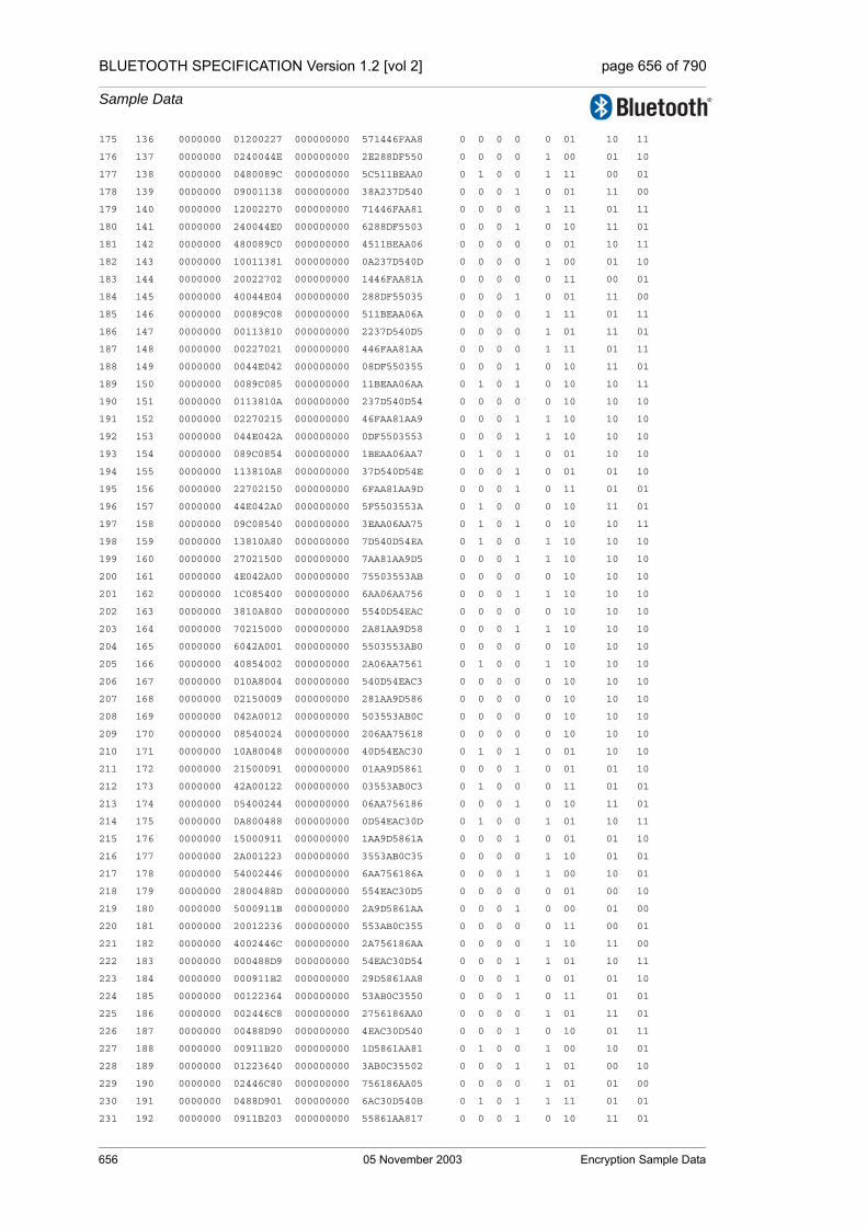
BLUETOOTH SPECIFICATION Version 1.2 [vol 2] page 656 of 790
Sample Data
175 136 0000000 01200227 000000000 571446FAA8 0 0 0 0 0 01 10 11
176 137 0000000 0240044E 000000000 2E288DF550 0 0 0 0 1 00 01 10
177 138 0000000 0480089C 000000000 5C511BEAA0 0 1 0 0 1 11 00 01
178 139 0000000 09001138 000000000 38A237D540 0 0 0 1 0 01 11 00
179 140 0000000 12002270 000000000 71446FAA81 0 0 0 0 1 11 01 11
180 141 0000000 240044E0 000000000 6288DF5503 0 0 0 1 0 10 11 01
181 142 0000000 480089C0 000000000 4511BEAA06 0 0 0 0 0 01 10 11
182 143 0000000 10011381 000000000 0A237D540D 0 0 0 0 1 00 01 10
183 144 0000000 20022702 000000000 1446FAA81A 0 0 0 0 0 11 00 01
184 145 0000000 40044E04 000000000 288DF55035 0 0 0 1 0 01 11 00
185 146 0000000 00089C08 000000000 511BEAA06A 0 0 0 0 1 11 01 11
186 147 0000000 00113810 000000000 2237D540D5 0 0 0 0 1 01 11 01
187 148 0000000 00227021 000000000 446FAA81AA 0 0 0 0 1 11 01 11
188 149 0000000 0044E042 000000000 08DF550355 0 0 0 1 0 10 11 01
189 150 0000000 0089C085 000000000 11BEAA06AA 0 1 0 1 0 10 10 11
190 151 0000000 0113810A 000000000 237D540D54 0 0 0 0 0 10 10 10
191 152 0000000 02270215 000000000 46FAA81AA9 0 0 0 1 1 10 10 10
192 153 0000000 044E042A 000000000 0DF5503553 0 0 0 1 1 10 10 10
193 154 0000000 089C0854 000000000 1BEAA06AA7 0 1 0 1 0 01 10 10
194 155 0000000 113810A8 000000000 37D540D54E 0 0 0 1 0 01 01 10
195 156 0000000 22702150 000000000 6FAA81AA9D 0 0 0 1 0 11 01 01
196 157 0000000 44E042A0 000000000 5F5503553A 0 1 0 0 0 10 11 01
197 158 0000000 09C08540 000000000 3EAA06AA75 0 1 0 1 0 10 10 11
198 159 0000000 13810A80 000000000 7D540D54EA 0 1 0 0 1 10 10 10
199 160 0000000 27021500 000000000 7AA81AA9D5 0 0 0 1 1 10 10 10
200 161 0000000 4E042A00 000000000 75503553AB 0 0 0 0 0 10 10 10
201 162 0000000 1C085400 000000000 6AA06AA756 0 0 0 1 1 10 10 10
202 163 0000000 3810A800 000000000 5540D54EAC 0 0 0 0 0 10 10 10
203 164 0000000 70215000 000000000 2A81AA9D58 0 0 0 1 1 10 10 10
204 165 0000000 6042A001 000000000 5503553AB0 0 0 0 0 0 10 10 10
205 166 0000000 40854002 000000000 2A06AA7561 0 1 0 0 1 10 10 10
206 167 0000000 010A8004 000000000 540D54EAC3 0 0 0 0 0 10 10 10
207 168 0000000 02150009 000000000 281AA9D586 0 0 0 0 0 10 10 10
208 169 0000000 042A0012 000000000 503553AB0C 0 0 0 0 0 10 10 10
209 170 0000000 08540024 000000000 206AA75618 0 0 0 0 0 10 10 10
210 171 0000000 10A80048 000000000 40D54EAC30 0 1 0 1 0 01 10 10
211 172 0000000 21500091 000000000 01AA9D5861 0 0 0 1 0 01 01 10
212 173 0000000 42A00122 000000000 03553AB0C3 0 1 0 0 0 11 01 01
213 174 0000000 05400244 000000000 06AA756186 0 0 0 1 0 10 11 01
214 175 0000000 0A800488 000000000 0D54EAC30D 0 1 0 0 1 01 10 11
215 176 0000000 15000911 000000000 1AA9D5861A 0 0 0 1 0 01 01 10
216 177 0000000 2A001223 000000000 3553AB0C35 0 0 0 0 1 10 01 01
217 178 0000000 54002446 000000000 6AA756186A 0 0 0 1 1 00 10 01
218 179 0000000 2800488D 000000000 554EAC30D5 0 0 0 0 0 01 00 10
219 180 0000000 5000911B 000000000 2A9D5861AA 0 0 0 1 0 00 01 00
220 181 0000000 20012236 000000000 553AB0C355 0 0 0 0 0 11 00 01
221 182 0000000 4002446C 000000000 2A756186AA 0 0 0 0 1 10 11 00
222 183 0000000 000488D9 000000000 54EAC30D54 0 0 0 1 1 01 10 11
223 184 0000000 000911B2 000000000 29D5861AA8 0 0 0 1 0 01 01 10
224 185 0000000 00122364 000000000 53AB0C3550 0 0 0 1 0 11 01 01
225 186 0000000 002446C8 000000000 2756186AA0 0 0 0 0 1 01 11 01
226 187 0000000 00488D90 000000000 4EAC30D540 0 0 0 1 0 10 01 11
227 188 0000000 00911B20 000000000 1D5861AA81 0 1 0 0 1 00 10 01
228 189 0000000 01223640 000000000 3AB0C35502 0 0 0 1 1 01 00 10
229 190 0000000 02446C80 000000000 756186AA05 0 0 0 0 1 01 01 00
230 191 0000000 0488D901 000000000 6AC30D540B 0 1 0 1 1 11 01 01
231 192 0000000 0911B203 000000000 55861AA817 0 0 0 1 0 10 11 01
656 05 November 2003 Encryption Sample Data

BLUETOOTH SPECIFICATION Version 1.2 [vol 2] page 657 of 790
Sample Data
232 193 0000000 12236407 000000000 2B0C35502F 0 0 0 0 0 01 10 11
233 194 0000000 2446C80E 000000000 56186AA05F 0 0 0 0 1 00 01 10
234 195 0000000 488D901C 000000000 2C30D540BF 0 1 0 0 1 11 00 01
235 196 0000000 111B2039 000000000 5861AA817E 0 0 0 0 1 10 11 00
236 197 0000000 22364072 000000000 30C35502FD 0 0 0 1 1 01 10 11
237 198 0000000 446C80E4 000000000 6186AA05FB 0 0 0 1 0 01 01 10
238 199 0000000 08D901C8 000000000 430D540BF6 0 1 0 0 0 11 01 01
239 200 0000000 11B20391 000000000 061AA817EC 0 1 0 0 0 10 11 01
Z[0] = 3D
Z[1] = C1
Z[2] = F0
Z[3] = BB
Z[4] = 58
Z[5] = 1E
Z[6] = 42
Z[7] = 42
Z[8] = 4B
Z[9] = 8E
Z[10] = C1
Z[11] = 2A
Z[12] = 40
Z[13] = 63
Z[14] = 7A
Z[15] = 1E
===============================================================================================
Reload this pattern into the LFSRs
Hold content of Summation Combiner regs and calculate new C[t+1] and Z values
===============================================================================================
LFSR1 <= 04B583D
LFSR2 <= 208E1EC1
LFSR3 <= 063C142F0
LFSR4 <= 0F7A2A42BB
C[t+1] <= 10
===============================================================================================
Generating 125 key symbols (encryption/decryption sequence)
===============================================================================================
240 1 04B583D 208E1EC1 063C142F0 0F7A2A42BB 0 1 0 0 0 10 11 01
241 2 096B07A 411C3D82 0C78285E1 1EF4548577 1 0 1 1 1 10 10 11
242 3 12D60F4 02387B04 18F050BC3 3DE8A90AEF 0 0 1 1 0 01 10 10
243 4 05AC1E9 0470F609 11E0A1786 7BD15215DF 0 0 0 1 0 01 01 10
244 5 0B583D2 08E1EC13 03C142F0C 77A2A42BBF 1 1 0 1 0 00 01 01
245 6 16B07A5 11C3D827 078285E18 6F4548577E 0 1 0 0 1 11 00 01
246 7 0D60F4B 2387B04F 0F050BC30 5E8A90AEFD 1 1 1 1 1 00 11 00
247 8 1AC1E97 470F609E 1E0A17860 3D15215DFA 1 0 1 0 0 11 00 11
248 9 1583D2E 0E1EC13D 1C142F0C0 7A2A42BBF4 0 0 1 0 0 01 11 00
249 10 0B07A5D 1C3D827B 18285E181 74548577E9 1 0 1 0 1 10 01 11
250 11 160F4BB 387B04F7 1050BC302 68A90AEFD2 0 0 0 1 1 00 10 01
251 12 0C1E976 70F609EE 00A178605 515215DFA5 1 1 0 0 0 00 00 10
252 13 183D2ED 61EC13DD 0142F0C0B 22A42BBF4B 1 1 0 1 1 01 00 00
253 14 107A5DA 43D827BA 0285E1817 4548577E97 0 1 0 0 0 00 01 00
254 15 00F4BB4 07B04F74 050BC302F 0A90AEFD2E 0 1 0 1 0 10 00 01
255 16 01E9769 0F609EE8 0A178605E 15215DFA5C 0 0 1 0 1 11 10 00
256 17 03D2ED3 1EC13DD0 142F0C0BD 2A42BBF4B9 0 1 0 0 0 00 11 10
257 18 07A5DA7 3D827BA0 085E1817B 548577E972 0 1 1 1 1 11 00 11
Encryption Sample Data 05 November 2003 657
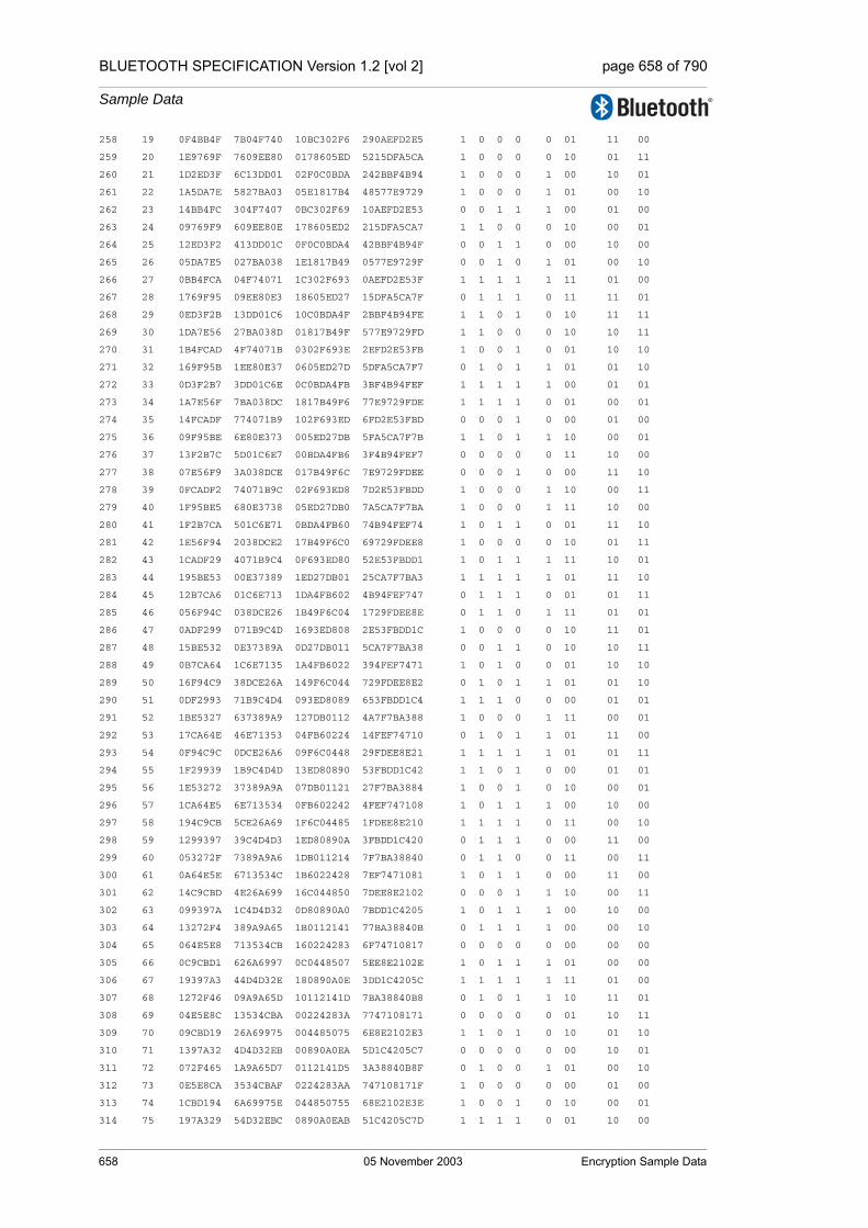
BLUETOOTH SPECIFICATION Version 1.2 [vol 2] page 658 of 790
Sample Data
258 19 0F4BB4F 7B04F740 10BC302F6 290AEFD2E5 1 0 0 0 0 01 11 00
259 20 1E9769F 7609EE80 0178605ED 5215DFA5CA 1 0 0 0 0 10 01 11
260 21 1D2ED3F 6C13DD01 02F0C0BDA 242BBF4B94 1 0 0 0 1 00 10 01
261 22 1A5DA7E 5827BA03 05E1817B4 48577E9729 1 0 0 0 1 01 00 10
262 23 14BB4FC 304F7407 0BC302F69 10AEFD2E53 0 0 1 1 1 00 01 00
263 24 09769F9 609EE80E 178605ED2 215DFA5CA7 1 1 0 0 0 10 00 01
264 25 12ED3F2 413DD01C 0F0C0BDA4 42BBF4B94F 0 0 1 1 0 00 10 00
265 26 05DA7E5 027BA038 1E1817B49 0577E9729F 0 0 1 0 1 01 00 10
266 27 0BB4FCA 04F74071 1C302F693 0AEFD2E53F 1 1 1 1 1 11 01 00
267 28 1769F95 09EE80E3 18605ED27 15DFA5CA7F 0 1 1 1 0 11 11 01
268 29 0ED3F2B 13DD01C6 10C0BDA4F 2BBF4B94FE 1 1 0 1 0 10 11 11
269 30 1DA7E56 27BA038D 01817B49F 577E9729FD 1 1 0 0 0 10 10 11
270 31 1B4FCAD 4F74071B 0302F693E 2EFD2E53FB 1 0 0 1 0 01 10 10
271 32 169F95B 1EE80E37 0605ED27D 5DFA5CA7F7 0 1 0 1 1 01 01 10
272 33 0D3F2B7 3DD01C6E 0C0BDA4FB 3BF4B94FEF 1 1 1 1 1 00 01 01
273 34 1A7E56F 7BA038DC 1817B49F6 77E9729FDE 1 1 1 1 0 01 00 01
274 35 14FCADF 774071B9 102F693ED 6FD2E53FBD 0 0 0 1 0 00 01 00
275 36 09F95BE 6E80E373 005ED27DB 5FA5CA7F7B 1 1 0 1 1 10 00 01
276 37 13F2B7C 5D01C6E7 00BDA4FB6 3F4B94FEF7 0 0 0 0 0 11 10 00
277 38 07E56F9 3A038DCE 017B49F6C 7E9729FDEE 0 0 0 1 0 00 11 10
278 39 0FCADF2 74071B9C 02F693ED8 7D2E53FBDD 1 0 0 0 1 10 00 11
279 40 1F95BE5 680E3738 05ED27DB0 7A5CA7F7BA 1 0 0 0 1 11 10 00
280 41 1F2B7CA 501C6E71 0BDA4FB60 74B94FEF74 1 0 1 1 0 01 11 10
281 42 1E56F94 2038DCE2 17B49F6C0 69729FDEE8 1 0 0 0 0 10 01 11
282 43 1CADF29 4071B9C4 0F693ED80 52E53FBDD1 1 0 1 1 1 11 10 01
283 44 195BE53 00E37389 1ED27DB01 25CA7F7BA3 1 1 1 1 1 01 11 10
284 45 12B7CA6 01C6E713 1DA4FB602 4B94FEF747 0 1 1 1 0 01 01 11
285 46 056F94C 038DCE26 1B49F6C04 1729FDEE8E 0 1 1 0 1 11 01 01
286 47 0ADF299 071B9C4D 1693ED808 2E53FBDD1C 1 0 0 0 0 10 11 01
287 48 15BE532 0E37389A 0D27DB011 5CA7F7BA38 0 0 1 1 0 10 10 11
288 49 0B7CA64 1C6E7135 1A4FB6022 394FEF7471 1 0 1 0 0 01 10 10
289 50 16F94C9 38DCE26A 149F6C044 729FDEE8E2 0 1 0 1 1 01 01 10
290 51 0DF2993 71B9C4D4 093ED8089 653FBDD1C4 1 1 1 0 0 00 01 01
291 52 1BE5327 637389A9 127DB0112 4A7F7BA388 1 0 0 0 1 11 00 01
292 53 17CA64E 46E71353 04FB60224 14FEF74710 0 1 0 1 1 01 11 00
293 54 0F94C9C 0DCE26A6 09F6C0448 29FDEE8E21 1 1 1 1 1 01 01 11
294 55 1F29939 1B9C4D4D 13ED80890 53FBDD1C42 1 1 0 1 0 00 01 01
295 56 1E53272 37389A9A 07DB01121 27F7BA3884 1 0 0 1 0 10 00 01
296 57 1CA64E5 6E713534 0FB602242 4FEF747108 1 0 1 1 1 00 10 00
297 58 194C9CB 5CE26A69 1F6C04485 1FDEE8E210 1 1 1 1 0 11 00 10
298 59 1299397 39C4D4D3 1ED80890A 3FBDD1C420 0 1 1 1 0 00 11 00
299 60 053272F 7389A9A6 1DB011214 7F7BA38840 0 1 1 0 0 11 00 11
300 61 0A64E5E 6713534C 1B6022428 7EF7471081 1 0 1 1 0 00 11 00
301 62 14C9CBD 4E26A699 16C044850 7DEE8E2102 0 0 0 1 1 10 00 11
302 63 099397A 1C4D4D32 0D80890A0 7BDD1C4205 1 0 1 1 1 00 10 00
303 64 13272F4 389A9A65 1B0112141 77BA38840B 0 1 1 1 1 00 00 10
304 65 064E5E8 713534CB 160224283 6F74710817 0 0 0 0 0 00 00 00
305 66 0C9CBD1 626A6997 0C0448507 5EE8E2102E 1 0 1 1 1 01 00 00
306 67 19397A3 44D4D32E 180890A0E 3DD1C4205C 1 1 1 1 1 11 01 00
307 68 1272F46 09A9A65D 10112141D 7BA38840B8 0 1 0 1 1 10 11 01
308 69 04E5E8C 13534CBA 00224283A 7747108171 0 0 0 0 0 01 10 11
309 70 09CBD19 26A69975 004485075 6E8E2102E3 1 1 0 1 0 10 01 10
310 71 1397A32 4D4D32EB 00890A0EA 5D1C4205C7 0 0 0 0 0 00 10 01
311 72 072F465 1A9A65D7 0112141D5 3A38840B8F 0 1 0 0 1 01 00 10
312 73 0E5E8CA 3534CBAF 0224283AA 747108171F 1 0 0 0 0 00 01 00
313 74 1CBD194 6A69975E 044850755 68E2102E3E 1 0 0 1 0 10 00 01
314 75 197A329 54D32EBC 0890A0EAB 51C4205C7D 1 1 1 1 0 01 10 00
658 05 November 2003 Encryption Sample Data

BLUETOOTH SPECIFICATION Version 1.2 [vol 2] page 659 of 790
Sample Data
315 76 12F4653 29A65D79 112141D56 238840B8FA 0 1 0 1 1 01 01 10
316 77 05E8CA6 534CBAF2 024283AAD 47108171F4 0 0 0 0 1 10 01 01
317 78 0BD194D 269975E5 04850755B 0E2102E3E9 1 1 0 0 0 11 10 01
318 79 17A329A 4D32EBCB 090A0EAB6 1C4205C7D2 0 0 1 0 0 00 11 10
319 80 0F46535 1A65D797 12141D56D 38840B8FA5 1 0 0 1 0 11 00 11
320 81 1E8CA6A 34CBAF2F 04283AADA 7108171F4B 1 1 0 0 1 01 11 00
321 82 1D194D5 69975E5F 0850755B4 62102E3E97 1 1 1 0 0 01 01 11
322 83 1A329AA 532EBCBF 10A0EAB68 44205C7D2F 1 0 0 0 0 11 01 01
323 84 1465355 265D797F 0141D56D1 0840B8FA5E 0 0 0 0 1 01 11 01
324 85 08CA6AB 4CBAF2FF 0283AADA2 108171F4BC 1 1 0 1 0 01 01 11
325 86 1194D56 1975E5FF 050755B45 2102E3E979 0 0 0 0 1 10 01 01
326 87 0329AAD 32EBCBFF 0A0EAB68A 4205C7D2F3 0 1 1 0 0 11 10 01
327 88 065355A 65D797FF 141D56D14 040B8FA5E7 0 1 0 0 0 00 11 10
328 89 0CA6AB4 4BAF2FFF 083AADA28 08171F4BCF 1 1 1 0 1 11 00 11
329 90 194D569 175E5FFF 10755B450 102E3E979E 1 0 0 0 0 01 11 00
330 91 129AAD3 2EBCBFFF 00EAB68A1 205C7D2F3C 0 1 0 0 0 10 01 11
331 92 05355A6 5D797FFF 01D56D142 40B8FA5E78 0 0 0 1 1 00 10 01
332 93 0A6AB4D 3AF2FFFE 03AADA285 0171F4BCF1 1 1 0 0 0 00 00 10
333 94 14D569B 75E5FFFD 0755B450A 02E3E979E2 0 1 0 1 0 01 00 00
334 95 09AAD37 6BCBFFFA 0EAB68A15 05C7D2F3C4 1 1 1 1 1 11 01 00
335 96 1355A6E 5797FFF4 1D56D142A 0B8FA5E788 0 1 1 1 0 11 11 01
336 97 06AB4DC 2F2FFFE8 1AADA2854 171F4BCF11 0 0 1 0 0 11 11 11
337 98 0D569B8 5E5FFFD0 155B450A9 2E3E979E23 1 0 0 0 0 11 11 11
338 99 1AAD370 3CBFFFA1 0AB68A153 5C7D2F3C46 1 1 1 0 0 10 11 11
339 100 155A6E0 797FFF43 156D142A7 38FA5E788D 0 0 0 1 1 01 10 11
340 101 0AB4DC0 72FFFE87 0ADA2854E 71F4BCF11B 1 1 1 1 1 10 01 10
341 102 1569B81 65FFFD0E 15B450A9D 63E979E236 0 1 0 1 0 11 10 01
342 103 0AD3703 4BFFFA1C 0B68A153B 47D2F3C46C 1 1 1 1 1 01 11 10
343 104 15A6E07 17FFF438 16D142A76 0FA5E788D8 0 1 0 1 1 10 01 11
344 105 0B4DC0F 2FFFE870 0DA2854EC 1F4BCF11B0 1 1 1 0 1 11 10 01
345 106 169B81F 5FFFD0E1 1B450A9D8 3E979E2360 0 1 1 1 0 01 11 10
346 107 0D3703F 3FFFA1C3 168A153B0 7D2F3C46C1 1 1 0 0 1 10 01 11
347 108 1A6E07E 7FFF4386 0D142A761 7A5E788D83 1 1 1 0 1 11 10 01
348 109 14DC0FD 7FFE870C 1A2854EC2 74BCF11B07 0 1 1 1 0 01 11 10
349 110 09B81FB 7FFD0E19 1450A9D84 6979E2360E 1 1 0 0 1 10 01 11
350 111 13703F6 7FFA1C33 08A153B09 52F3C46C1C 0 1 1 1 1 11 10 01
351 112 06E07EC 7FF43867 1142A7612 25E788D838 0 1 0 1 1 00 11 10
352 113 0DC0FD8 7FE870CF 02854EC25 4BCF11B071 1 1 0 1 1 11 00 11
353 114 1B81FB1 7FD0E19E 050A9D84B 179E2360E3 1 1 0 1 0 00 11 00
354 115 1703F62 7FA1C33D 0A153B096 2F3C46C1C7 0 1 1 0 0 11 00 11
355 116 0E07EC4 7F43867B 142A7612C 5E788D838E 1 0 0 0 0 01 11 00
356 117 1C0FD88 7E870CF6 0854EC259 3CF11B071C 1 1 1 1 1 01 01 11
357 118 181FB11 7D0E19ED 10A9D84B3 79E2360E38 1 0 0 1 1 11 01 01
358 119 103F622 7A1C33DA 0153B0967 73C46C1C71 0 0 0 1 0 10 11 01
359 120 007EC45 743867B5 02A7612CE 6788D838E3 0 0 0 1 1 01 10 11
360 121 00FD88B 6870CF6B 054EC259C 4F11B071C6 0 0 0 0 1 00 01 10
361 122 01FB117 50E19ED7 0A9D84B38 1E2360E38C 0 1 1 0 0 10 00 01
362 123 03F622F 21C33DAE 153B09671 3C46C1C718 0 1 0 0 1 11 10 00
363 124 07EC45F 43867B5C 0A7612CE2 788D838E30 0 1 1 1 0 01 11 10
364 125 0FD88BF 070CF6B9 14EC259C4 711B071C61 1 0 0 0 0 10 01 11
Encryption Sample Data 05 November 2003 659

BLUETOOTH SPECIFICATION Version 1.2 [vol 2] page 660 of 790
Sample Data
1.3 SECOND SET OF SAMPLE DATA
Initial values for the key, BD_ADDR and clock
K’c2[0] = 00 K’c2[1] = 00 K’c2[2] = 00 K’c2[3] = 00
K’c2[4] = 00 K’c2[5] = 00 K’c2[6] = 00 K’c2[7] = 00
K’c2[8] = 00 K’c2[9] = 00 K’c2[10] = 00 K’c2[11] = 00
K’c2[12] = 00 K’c2[13] = 00 K’c2[14] = 00 K’c2[15] = 00
Addr2[0] = 00 Addr2[1] = 00 Addr2[2] = 00
Addr2[3] = 00 Addr2[4] = 00 Addr2[5] = 00
CL2[0] = 00 CL2[1] = 00 CL2[2] = 00 CL2[3] = 03
===============================================================================================
Fill LFSRs with initial data
===============================================================================================
t clk# LFSR1 LFSR2 LFSR3 LFSR4 X1 X2 X3 X4 Z C[t+1] C[t] C[t-1]
0 0 0000000* 00000000* 000000000* 0000000000* 0 0 0 0 0 00 00 00
1 1 0000001* 00000001* 000000001* 0000000001* 0 0 0 0 0 00 00 00
2 2 0000002* 00000002* 000000002* 0000000003* 0 0 0 0 0 00 00 00
3 3 0000004* 00000004* 000000004* 0000000007* 0 0 0 0 0 00 00 00
4 4 0000008* 00000008* 000000008* 000000000E* 0 0 0 0 0 00 00 00
5 5 0000010* 00000010* 000000010* 000000001C* 0 0 0 0 0 00 00 00
6 6 0000020* 00000020* 000000020* 0000000038* 0 0 0 0 0 00 00 00
7 7 0000040* 00000040* 000000040* 0000000070* 0 0 0 0 0 00 00 00
8 8 0000080* 00000080* 000000080* 00000000E0* 0 0 0 0 0 00 00 00
9 9 0000100* 00000100* 000000100* 00000001C0* 0 0 0 0 0 00 00 00
10 10 0000200* 00000200* 000000200* 0000000380* 0 0 0 0 0 00 00 00
11 11 0000400* 00000400* 000000400* 0000000700* 0 0 0 0 0 00 00 00
12 12 0000800* 00000800* 000000800* 0000000E00* 0 0 0 0 0 00 00 00
13 13 0001000* 00001000* 000001000* 0000001C00* 0 0 0 0 0 00 00 00
14 14 0002000* 00002000* 000002000* 0000003800* 0 0 0 0 0 00 00 00
15 15 0004000* 00004000* 000004000* 0000007000* 0 0 0 0 0 00 00 00
16 16 0008000* 00008000* 000008000* 000000E000* 0 0 0 0 0 00 00 00
17 17 0010000* 00010000* 000010000* 000001C000* 0 0 0 0 0 00 00 00
18 18 0020000* 00020000* 000020000* 0000038000* 0 0 0 0 0 00 00 00
19 19 0040000* 00040000* 000040000* 0000070000* 0 0 0 0 0 00 00 00
20 20 0080000* 00080000* 000080000* 00000E0000* 0 0 0 0 0 00 00 00
21 21 0100000* 00100000* 000100000* 00001C0000* 0 0 0 0 0 00 00 00
22 22 0200000* 00200000* 000200000* 0000380000* 0 0 0 0 0 00 00 00
23 23 0400000* 00400000* 000400000* 0000700000* 0 0 0 0 0 00 00 00
24 24 0800000* 00800000* 000800000* 0000E00000* 1 1 0 0 0 01 00 00
25 25 1000000* 01000000* 001000000* 0001C00000* 0 0 0 0 0 00 00 00
26 26 0000001 02000000* 002000000* 0003800000* 0 0 0 0 0 00 00 00
27 27 0000002 04000000* 004000000* 0007000000* 0 0 0 0 0 00 00 00
28 28 0000004 08000000* 008000000* 000E000000* 0 0 0 0 0 00 00 00
29 29 0000008 10000000* 010000000* 001C000000* 0 0 0 0 0 00 00 00
30 30 0000010 20000000* 020000000* 0038000000* 0 0 0 0 0 00 00 00
31 31 0000020 40000000* 040000000* 0070000000* 0 0 0 0 0 00 00 00
32 32 0000040 00000001 080000000* 00E0000000* 0 0 1 1 0 01 00 00
33 33 0000080 00000002 100000000* 01C0000000* 0 0 0 1 1 00 00 00
34 34 0000101 00000004 000000001 0380000000* 0 0 0 1 1 00 00 00
660 05 November 2003 Encryption Sample Data

BLUETOOTH SPECIFICATION Version 1.2 [vol 2] page 661 of 790
Sample Data
35 35 0000202 00000008 000000002 0700000000* 0 0 0 0 0 00 00 00
36 36 0000404 00000010 000000004 0E00000000* 0 0 0 0 0 00 00 00
37 37 0000808 00000020 000000008 1C00000000* 0 0 0 0 0 00 00 00
38 38 0001011 00000040 000000011 3800000000* 0 0 0 0 0 00 00 00
39 39 0002022 00000080 000000022 7000000000* 0 0 0 0 0 00 00 00
===============================================================================================
Start clocking Summation Combiner
===============================================================================================
40 1 0004044 00000100 000000044 6000000001 0 0 0 0 0 00 00 00
41 2 0008088 00000200 000000088 4000000003 0 0 0 0 0 00 00 00
42 3 0010111 00000400 000000111 0000000007 0 0 0 0 0 00 00 00
43 4 0020222 00000800 000000222 000000000E 0 0 0 0 0 00 00 00
44 5 0040444 00001001 000000444 000000001D 0 0 0 0 0 00 00 00
45 6 0080888 00002002 000000888 000000003B 0 0 0 0 0 00 00 00
46 7 0101111 00004004 000001111 0000000077 0 0 0 0 0 00 00 00
47 8 0202222 00008008 000002222 00000000EE 0 0 0 0 0 00 00 00
48 9 0404444 00010011 000004444 00000001DD 0 0 0 0 0 00 00 00
49 10 0808888 00020022 000008888 00000003BB 1 0 0 0 1 00 00 00
50 11 1011110 00040044 000011111 0000000777 0 0 0 0 0 00 00 00
51 12 0022221 00080088 000022222 0000000EEE 0 0 0 0 0 00 00 00
52 13 0044442 00100110 000044444 0000001DDD 0 0 0 0 0 00 00 00
53 14 0088884 00200220 000088888 0000003BBB 0 0 0 0 0 00 00 00
54 15 0111109 00400440 000111111 0000007777 0 0 0 0 0 00 00 00
55 16 0222212 00800880 000222222 000000EEEE 0 1 0 0 1 00 00 00
56 17 0444424 01001100 000444444 000001DDDD 0 0 0 0 0 00 00 00
57 18 0888848 02002200 000888888 000003BBBB 1 0 0 0 1 00 00 00
58 19 1111090 04004400 001111110 0000077777 0 0 0 0 0 00 00 00
59 20 0222120 08008800 002222220 00000EEEEE 0 0 0 0 0 00 00 00
60 21 0444240 10011000 004444440 00001DDDDD 0 0 0 0 0 00 00 00
61 22 0888480 20022000 008888880 00003BBBBB 1 0 0 0 1 00 00 00
62 23 1110900 40044000 011111100 0000777777 0 0 0 0 0 00 00 00
63 24 0221200 00088001 022222200 0000EEEEEE 0 0 0 0 0 00 00 00
64 25 0442400 00110003 044444400 0001DDDDDD 0 0 0 0 0 00 00 00
65 26 0884800 00220006 088888800 0003BBBBBB 1 0 1 0 0 01 00 00
66 27 1109000 0044000C 111111000 0007777777 0 0 0 0 1 01 01 00
67 28 0212001 00880018 022222001 000EEEEEEE 0 1 0 0 0 11 01 01
68 29 0424002 01100031 044444002 001DDDDDDC 0 0 0 0 1 01 11 01
69 30 0848004 02200062 088888004 003BBBBBB8 1 0 1 0 1 10 01 11
70 31 1090008 044000C4 111110008 0077777770 0 0 0 0 0 00 10 01
71 32 0120010 08800188 022220010 00EEEEEEE0 0 1 0 1 0 00 00 10
72 33 0240020 11000311 044440020 01DDDDDDC1 0 0 0 1 1 00 00 00
73 34 0480040 22000622 088880040 03BBBBBB83 0 0 1 1 0 01 00 00
74 35 0900081 44000C44 111100080 0777777707 1 0 0 0 0 00 01 00
75 36 1200103 08001888 022200101 0EEEEEEE0E 0 0 0 1 1 11 00 01
76 37 0400207 10003111 044400202 1DDDDDDC1D 0 0 0 1 0 01 11 00
77 38 080040E 20006222 088800404 3BBBBBB83B 1 0 1 1 0 01 01 11
78 39 100081C 4000C444 111000808 7777777077 0 0 0 0 1 10 01 01
79 40 0001038 00018888 022001010 6EEEEEE0EF 0 0 0 1 1 00 10 01
80 41 0002070 00031110 044002020 5DDDDDC1DE 0 0 0 1 1 01 00 10
81 42 00040E0 00062220 088004040 3BBBBB83BC 0 0 1 1 1 00 01 00
82 43 00081C1 000C4440 110008081 7777770779 0 0 0 0 0 11 00 01
83 44 0010383 00188880 020010103 6EEEEE0EF2 0 0 0 1 0 01 11 00
84 45 0020707 00311100 040020206 5DDDDC1DE5 0 0 0 1 0 10 01 11
85 46 0040E0E 00622200 08004040C 3BBBB83BCB 0 0 1 1 0 11 10 01
86 47 0081C1D 00C44400 100080819 7777707797 0 1 0 0 0 00 11 10
87 48 010383A 01888801 000101032 6EEEE0EF2F 0 1 0 1 0 11 00 11
88 49 0207075 03111003 000202064 5DDDC1DE5E 0 0 0 1 0 01 11 00
Encryption Sample Data 05 November 2003 661

BLUETOOTH SPECIFICATION Version 1.2 [vol 2] page 662 of 790
Sample Data
89 50 040E0EA 06222006 0004040C8 3BBB83BCBC 0 0 0 1 0 10 01 11
90 51 081C1D5 0C44400C 000808191 7777077979 1 0 0 0 1 00 10 01
91 52 10383AB 18888018 001010323 6EEE0EF2F2 0 1 0 1 0 00 00 10
92 53 0070756 31110030 002020646 5DDC1DE5E5 0 0 0 1 1 00 00 00
93 54 00E0EAC 62220060 004040C8C 3BB83BCBCB 0 0 0 1 1 00 00 00
94 55 01C1D59 444400C1 008081919 7770779797 0 0 0 0 0 00 00 00
95 56 0383AB2 08880183 010103232 6EE0EF2F2F 0 1 0 1 0 01 00 00
96 57 0707565 11100307 020206464 5DC1DE5E5F 0 0 0 1 0 00 01 00
97 58 0E0EACA 2220060E 04040C8C8 3B83BCBCBF 1 0 0 1 0 10 00 01
98 59 1C1D594 44400C1C 080819191 770779797E 1 0 1 0 0 00 10 00
99 60 183AB28 08801838 101032323 6E0EF2F2FC 1 1 0 0 0 00 00 10
100 61 1075650 11003070 002064647 5C1DE5E5F8 0 0 0 0 0 00 00 00
101 62 00EACA1 220060E0 0040C8C8E 383BCBCBF0 0 0 0 0 0 00 00 00
102 63 01D5943 4400C1C0 00819191D 70779797E0 0 0 0 0 0 00 00 00
103 64 03AB286 08018380 01032323A 60EF2F2FC1 0 0 0 1 1 00 00 00
104 65 075650C 10030701 020646475 41DE5E5F82 0 0 0 1 1 00 00 00
105 66 0EACA18 20060E02 040C8C8EA 03BCBCBF04 1 0 0 1 0 01 00 00
106 67 1D59430 400C1C05 0819191D4 0779797E09 1 0 1 0 1 00 01 00
107 68 1AB2861 0018380A 1032323A9 0EF2F2FC12 1 0 0 1 0 10 00 01
108 69 15650C3 00307015 006464752 1DE5E5F825 0 0 0 1 1 11 10 00
109 70 0ACA186 0060E02A 00C8C8EA4 3BCBCBF04B 1 0 0 1 1 00 11 10
110 71 159430C 00C1C055 019191D48 779797E097 0 1 0 1 0 11 00 11
111 72 0B28618 018380AA 032323A90 6F2F2FC12F 1 1 0 0 1 01 11 00
112 73 1650C30 03070154 064647520 5E5E5F825E 0 0 0 0 1 11 01 11
113 74 0CA1860 060E02A8 0C8C8EA40 3CBCBF04BC 1 0 1 1 0 11 11 01
114 75 19430C0 0C1C0550 19191D480 79797E0979 1 0 1 0 1 11 11 11
115 76 1286180 18380AA0 12323A900 72F2FC12F2 0 0 0 1 0 11 11 11
116 77 050C301 30701541 046475201 65E5F825E5 0 0 0 1 0 11 11 11
117 78 0A18602 60E02A82 08C8EA402 4BCBF04BCB 1 1 1 1 1 10 11 11
118 79 1430C04 41C05505 1191D4804 1797E09796 0 1 0 1 0 10 10 11
119 80 0861808 0380AA0A 0323A9008 2F2FC12F2C 1 1 0 0 0 01 10 10
120 81 10C3011 07015415 064752011 5E5F825E59 0 0 0 0 1 00 01 10
121 82 0186022 0E02A82A 0C8EA4022 3CBF04BCB2 0 0 1 1 0 10 00 01
122 83 030C045 1C055054 191D48044 797E097964 0 0 1 0 1 11 10 00
123 84 061808A 380AA0A8 123A90088 72FC12F2C9 0 0 0 1 0 00 11 10
124 85 0C30115 70154151 047520111 65F825E593 1 0 0 1 0 11 00 11
125 86 186022A 602A82A3 08EA40222 4BF04BCB26 1 0 1 1 0 00 11 00
126 87 10C0455 40550546 11D480444 17E097964C 0 0 0 1 1 10 00 11
127 88 01808AA 00AA0A8D 03A900888 2FC12F2C99 0 1 0 1 0 00 10 00
128 89 0301155 0154151A 075201111 5F825E5932 0 0 0 1 1 01 00 10
129 90 06022AA 02A82A34 0EA402222 3F04BCB264 0 1 1 0 1 00 01 00
130 91 0C04555 05505468 1D4804445 7E097964C9 1 0 1 0 0 10 00 01
131 92 1808AAA 0AA0A8D0 1A900888A 7C12F2C992 1 1 1 0 1 00 10 00
132 93 1011555 154151A1 152011115 7825E59324 0 0 0 0 0 01 00 10
133 94 0022AAB 2A82A342 0A402222B 704BCB2648 0 1 1 0 1 00 01 00
134 95 0045556 55054684 148044457 6097964C91 0 0 0 1 1 11 00 01
135 96 008AAAC 2A0A8D09 0900888AE 412F2C9923 0 0 1 0 0 01 11 00
136 97 0115559 54151A12 12011115D 025E593246 0 0 0 0 1 11 01 11
137 98 022AAB2 282A3424 0402222BA 04BCB2648D 0 0 0 1 0 10 11 01
138 99 0455564 50546848 080444575 097964C91A 0 0 1 0 1 01 10 11
139 100 08AAAC8 20A8D090 100888AEA 12F2C99235 1 1 0 1 0 10 01 10
140 101 1155591 4151A120 0011115D5 25E593246A 0 0 0 1 1 00 10 01
141 102 02AAB22 02A34240 002222BAA 4BCB2648D5 0 1 0 1 0 00 00 10
142 103 0555644 05468481 004445755 17964C91AB 0 0 0 1 1 00 00 00
143 104 0AAAC88 0A8D0903 00888AEAA 2F2C992357 1 1 0 0 0 01 00 00
144 105 1555911 151A1206 011115D55 5E593246AE 0 0 0 0 1 01 01 00
145 106 0AAB222 2A34240C 02222BAAA 3CB2648D5C 1 0 0 1 1 11 01 01
662 05 November 2003 Encryption Sample Data
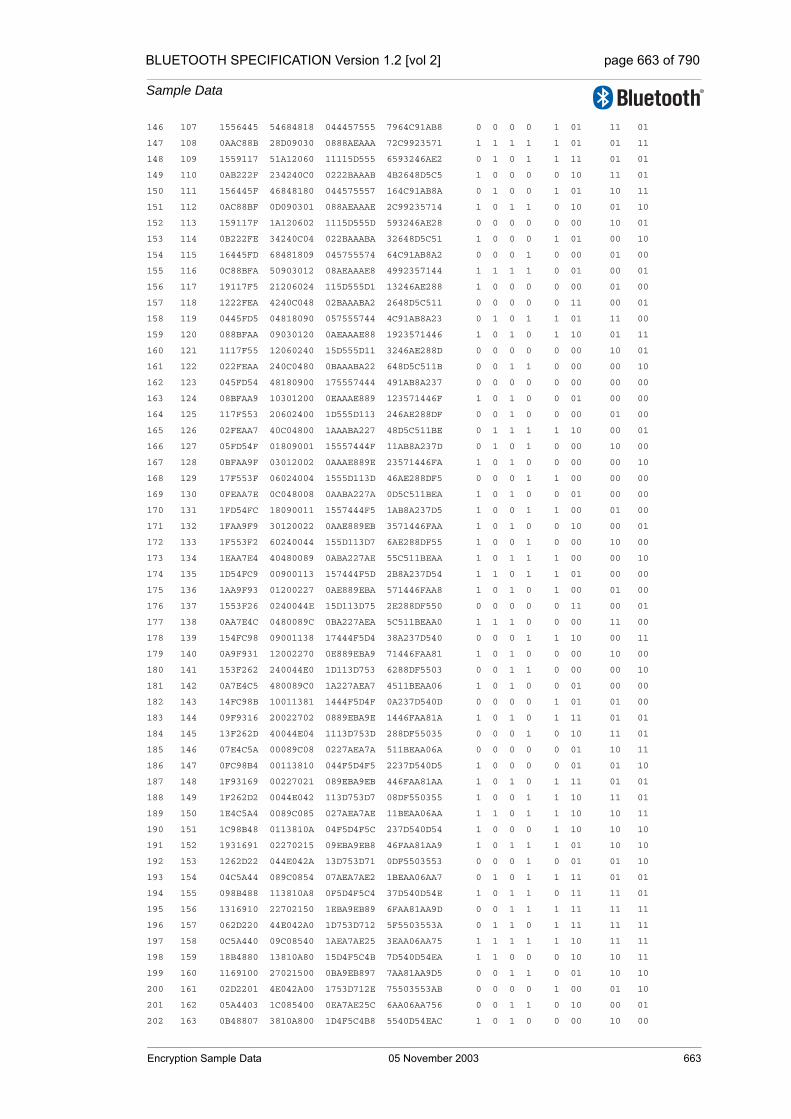
BLUETOOTH SPECIFICATION Version 1.2 [vol 2] page 663 of 790
Sample Data
146 107 1556445 54684818 044457555 7964C91AB8 0 0 0 0 1 01 11 01
147 108 0AAC88B 28D09030 0888AEAAA 72C9923571 1 1 1 1 1 01 01 11
148 109 1559117 51A12060 11115D555 6593246AE2 0 1 0 1 1 11 01 01
149 110 0AB222F 234240C0 0222BAAAB 4B2648D5C5 1 0 0 0 0 10 11 01
150 111 156445F 46848180 044575557 164C91AB8A 0 1 0 0 1 01 10 11
151 112 0AC88BF 0D090301 088AEAAAE 2C99235714 1 0 1 1 0 10 01 10
152 113 159117F 1A120602 1115D555D 593246AE28 0 0 0 0 0 00 10 01
153 114 0B222FE 34240C04 022BAAABA 32648D5C51 1 0 0 0 1 01 00 10
154 115 16445FD 68481809 045755574 64C91AB8A2 0 0 0 1 0 00 01 00
155 116 0C88BFA 50903012 08AEAAAE8 4992357144 1 1 1 1 0 01 00 01
156 117 19117F5 21206024 115D555D1 13246AE288 1 0 0 0 0 00 01 00
157 118 1222FEA 4240C048 02BAAABA2 2648D5C511 0 0 0 0 0 11 00 01
158 119 0445FD5 04818090 057555744 4C91AB8A23 0 1 0 1 1 01 11 00
159 120 088BFAA 09030120 0AEAAAE88 1923571446 1 0 1 0 1 10 01 11
160 121 1117F55 12060240 15D555D11 3246AE288D 0 0 0 0 0 00 10 01
161 122 022FEAA 240C0480 0BAAABA22 648D5C511B 0 0 1 1 0 00 00 10
162 123 045FD54 48180900 175557444 491AB8A237 0 0 0 0 0 00 00 00
163 124 08BFAA9 10301200 0EAAAE889 123571446F 1 0 1 0 0 01 00 00
164 125 117F553 20602400 1D555D113 246AE288DF 0 0 1 0 0 00 01 00
165 126 02FEAA7 40C04800 1AAABA227 48D5C511BE 0 1 1 1 1 10 00 01
166 127 05FD54F 01809001 15557444F 11AB8A237D 0 1 0 1 0 00 10 00
167 128 0BFAA9F 03012002 0AAAE889E 23571446FA 1 0 1 0 0 00 00 10
168 129 17F553F 06024004 1555D113D 46AE288DF5 0 0 0 1 1 00 00 00
169 130 0FEAA7E 0C048008 0AABA227A 0D5C511BEA 1 0 1 0 0 01 00 00
170 131 1FD54FC 18090011 1557444F5 1AB8A237D5 1 0 0 1 1 00 01 00
171 132 1FAA9F9 30120022 0AAE889EB 3571446FAA 1 0 1 0 0 10 00 01
172 133 1F553F2 60240044 155D113D7 6AE288DF55 1 0 0 1 0 00 10 00
173 134 1EAA7E4 40480089 0ABA227AE 55C511BEAA 1 0 1 1 1 00 00 10
174 135 1D54FC9 00900113 157444F5D 2B8A237D54 1 1 0 1 1 01 00 00
175 136 1AA9F93 01200227 0AE889EBA 571446FAA8 1 0 1 0 1 00 01 00
176 137 1553F26 0240044E 15D113D75 2E288DF550 0 0 0 0 0 11 00 01
177 138 0AA7E4C 0480089C 0BA227AEA 5C511BEAA0 1 1 1 0 0 00 11 00
178 139 154FC98 09001138 17444F5D4 38A237D540 0 0 0 1 1 10 00 11
179 140 0A9F931 12002270 0E889EBA9 71446FAA81 1 0 1 0 0 00 10 00
180 141 153F262 240044E0 1D113D753 6288DF5503 0 0 1 1 0 00 00 10
181 142 0A7E4C5 480089C0 1A227AEA7 4511BEAA06 1 0 1 0 0 01 00 00
182 143 14FC98B 10011381 1444F5D4F 0A237D540D 0 0 0 0 1 01 01 00
183 144 09F9316 20022702 0889EBA9E 1446FAA81A 1 0 1 0 1 11 01 01
184 145 13F262D 40044E04 1113D753D 288DF55035 0 0 0 1 0 10 11 01
185 146 07E4C5A 00089C08 0227AEA7A 511BEAA06A 0 0 0 0 0 01 10 11
186 147 0FC98B4 00113810 044F5D4F5 2237D540D5 1 0 0 0 0 01 01 10
187 148 1F93169 00227021 089EBA9EB 446FAA81AA 1 0 1 0 1 11 01 01
188 149 1F262D2 0044E042 113D753D7 08DF550355 1 0 0 1 1 10 11 01
189 150 1E4C5A4 0089C085 027AEA7AE 11BEAA06AA 1 1 0 1 1 10 10 11
190 151 1C98B48 0113810A 04F5D4F5C 237D540D54 1 0 0 0 1 10 10 10
191 152 1931691 02270215 09EBA9EB8 46FAA81AA9 1 0 1 1 1 01 10 10
192 153 1262D22 044E042A 13D753D71 0DF5503553 0 0 0 1 0 01 01 10
193 154 04C5A44 089C0854 07AEA7AE2 1BEAA06AA7 0 1 0 1 1 11 01 01
194 155 098B488 113810A8 0F5D4F5C4 37D540D54E 1 0 1 1 0 11 11 01
195 156 1316910 22702150 1EBA9EB89 6FAA81AA9D 0 0 1 1 1 11 11 11
196 157 062D220 44E042A0 1D753D712 5F5503553A 0 1 1 0 1 11 11 11
197 158 0C5A440 09C08540 1AEA7AE25 3EAA06AA75 1 1 1 1 1 10 11 11
198 159 18B4880 13810A80 15D4F5C4B 7D540D54EA 1 1 0 0 0 10 10 11
199 160 1169100 27021500 0BA9EB897 7AA81AA9D5 0 0 1 1 0 01 10 10
200 161 02D2201 4E042A00 1753D712E 75503553AB 0 0 0 0 1 00 01 10
201 162 05A4403 1C085400 0EA7AE25C 6AA06AA756 0 0 1 1 0 10 00 01
202 163 0B48807 3810A800 1D4F5C4B8 5540D54EAC 1 0 1 0 0 00 10 00
Encryption Sample Data 05 November 2003 663
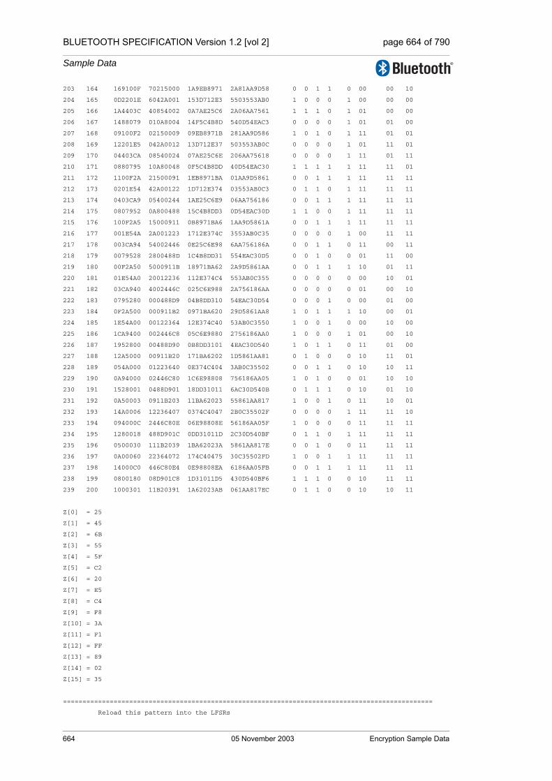
BLUETOOTH SPECIFICATION Version 1.2 [vol 2] page 664 of 790
Sample Data
203 164 169100F 70215000 1A9EB8971 2A81AA9D58 0 0 1 1 0 00 00 10
204 165 0D2201E 6042A001 153D712E3 5503553AB0 1 0 0 0 1 00 00 00
205 166 1A4403C 40854002 0A7AE25C6 2A06AA7561 1 1 1 0 1 01 00 00
206 167 1488079 010A8004 14F5C4B8D 540D54EAC3 0 0 0 0 1 01 01 00
207 168 09100F2 02150009 09EB8971B 281AA9D586 1 0 1 0 1 11 01 01
208 169 12201E5 042A0012 13D712E37 503553AB0C 0 0 0 0 1 01 11 01
209 170 04403CA 08540024 07AE25C6E 206AA75618 0 0 0 0 1 11 01 11
210 171 0880795 10A80048 0F5C4B8DD 40D54EAC30 1 1 1 1 1 11 11 01
211 172 1100F2A 21500091 1EB8971BA 01AA9D5861 0 0 1 1 1 11 11 11
212 173 0201E54 42A00122 1D712E374 03553AB0C3 0 1 1 0 1 11 11 11
213 174 0403CA9 05400244 1AE25C6E9 06AA756186 0 0 1 1 1 11 11 11
214 175 0807952 0A800488 15C4B8DD3 0D54EAC30D 1 1 0 0 1 11 11 11
215 176 100F2A5 15000911 0B8971BA6 1AA9D5861A 0 0 1 1 1 11 11 11
216 177 001E54A 2A001223 1712E374C 3553AB0C35 0 0 0 0 1 00 11 11
217 178 003CA94 54002446 0E25C6E98 6AA756186A 0 0 1 1 0 11 00 11
218 179 0079528 2800488D 1C4B8DD31 554EAC30D5 0 0 1 0 0 01 11 00
219 180 00F2A50 5000911B 18971BA62 2A9D5861AA 0 0 1 1 1 10 01 11
220 181 01E54A0 20012236 112E374C4 553AB0C355 0 0 0 0 0 00 10 01
221 182 03CA940 4002446C 025C6E988 2A756186AA 0 0 0 0 0 01 00 10
222 183 0795280 000488D9 04B8DD310 54EAC30D54 0 0 0 1 0 00 01 00
223 184 0F2A500 000911B2 0971BA620 29D5861AA8 1 0 1 1 1 10 00 01
224 185 1E54A00 00122364 12E374C40 53AB0C3550 1 0 0 1 0 00 10 00
225 186 1CA9400 002446C8 05C6E9880 2756186AA0 1 0 0 0 1 01 00 10
226 187 1952800 00488D90 0B8DD3101 4EAC30D540 1 0 1 1 0 11 01 00
227 188 12A5000 00911B20 171BA6202 1D5861AA81 0 1 0 0 0 10 11 01
228 189 054A000 01223640 0E374C404 3AB0C35502 0 0 1 1 0 10 10 11
229 190 0A94000 02446C80 1C6E98808 756186AA05 1 0 1 0 0 01 10 10
230 191 1528001 0488D901 18DD31011 6AC30D540B 0 1 1 1 0 10 01 10
231 192 0A50003 0911B203 11BA62023 55861AA817 1 0 0 1 0 11 10 01
232 193 14A0006 12236407 0374C4047 2B0C35502F 0 0 0 0 1 11 11 10
233 194 094000C 2446C80E 06E98808E 56186AA05F 1 0 0 0 0 11 11 11
234 195 1280018 488D901C 0DD31011D 2C30D540BF 0 1 1 0 1 11 11 11
235 196 0500030 111B2039 1BA62023A 5861AA817E 0 0 1 0 0 11 11 11
236 197 0A00060 22364072 174C40475 30C35502FD 1 0 0 1 1 11 11 11
237 198 14000C0 446C80E4 0E98808EA 6186AA05FB 0 0 1 1 1 11 11 11
238 199 0800180 08D901C8 1D31011D5 430D540BF6 1 1 1 0 0 10 11 11
239 200 1000301 11B20391 1A62023AB 061AA817EC 0 1 1 0 0 10 10 11
Z[0] = 25
Z[1] = 45
Z[2] = 6B
Z[3] = 55
Z[4] = 5F
Z[5] = C2
Z[6] = 20
Z[7] = E5
Z[8] = C4
Z[9] = F8
Z[10] = 3A
Z[11] = F1
Z[12] = FF
Z[13] = 89
Z[14] = 02
Z[15] = 35
===============================================================================================
Reload this pattern into the LFSRs
664 05 November 2003 Encryption Sample Data

BLUETOOTH SPECIFICATION Version 1.2 [vol 2] page 665 of 790
Sample Data
Hold content of Summation Combiner regs and calculate new C[t+1] and Z values
===============================================================================================
LFSR1 <= 1C45F25
LFSR2 <= 7FF8C245
LFSR3 <= 1893A206B
LFSR4 <= 1A02F1E555
C[t+1] <= 10
===============================================================================================
Generating 125 key symbols (encryption/decryption sequence)
===============================================================================================
240 1 1C45F25 7FF8C245 1893A206B 1A02F1E555 1 1 1 0 1 10 10 11
241 2 188BE4A 7FF1848B 1127440D7 3405E3CAAB 1 1 0 0 0 01 10 10
242 3 1117C95 7FE30917 024E881AF 680BC79557 0 1 0 0 0 01 01 10
243 4 022F92B 7FC6122F 049D1035E 50178F2AAF 0 1 0 0 0 11 01 01
244 5 045F257 7F8C245E 093A206BD 202F1E555E 0 1 1 0 1 10 11 01
245 6 08BE4AE 7F1848BC 127440D7A 405E3CAABC 1 0 0 0 1 01 10 11
246 7 117C95C 7E309178 04E881AF4 00BC795579 0 0 0 1 0 01 01 10
247 8 02F92B8 7C6122F0 09D1035E8 0178F2AAF2 0 0 1 0 0 11 01 01
248 9 05F2570 78C245E1 13A206BD0 02F1E555E5 0 1 0 1 1 10 11 01
249 10 0BE4AE1 71848BC2 07440D7A0 05E3CAABCA 1 1 0 1 1 10 10 11
250 11 17C95C3 63091784 0E881AF40 0BC7955795 0 0 1 1 0 01 10 10
251 12 0F92B87 46122F09 1D1035E80 178F2AAF2B 1 0 1 1 0 10 01 10
252 13 1F2570F 0C245E12 1A206BD01 2F1E555E56 1 0 1 0 0 11 10 01
253 14 1E4AE1F 1848BC25 1440D7A03 5E3CAABCAC 1 0 0 0 0 00 11 10
254 15 1C95C3E 3091784A 0881AF407 3C79557958 1 1 1 0 1 11 00 11
255 16 192B87D 6122F094 11035E80F 78F2AAF2B1 1 0 0 1 1 01 11 00
256 17 12570FA 4245E128 0206BD01E 71E555E562 0 0 0 1 0 10 01 11
257 18 04AE1F4 048BC250 040D7A03D 63CAABCAC5 0 1 0 1 0 11 10 01
258 19 095C3E8 091784A0 081AF407A 479557958A 1 0 1 1 0 01 11 10
259 20 12B87D1 122F0941 1035E80F4 0F2AAF2B14 0 0 0 0 1 11 01 11
260 21 0570FA3 245E1283 006BD01E9 1E555E5628 0 0 0 0 1 01 11 01
261 22 0AE1F46 48BC2506 00D7A03D2 3CAABCAC50 1 1 0 1 0 01 01 11
262 23 15C3E8C 11784A0C 01AF407A5 79557958A0 0 0 0 0 1 10 01 01
263 24 0B87D18 22F09419 035E80F4A 72AAF2B140 1 1 0 1 1 11 10 01
264 25 170FA30 45E12832 06BD01E94 6555E56280 0 1 0 0 0 00 11 10
265 26 0E1F460 0BC25065 0D7A03D28 4AABCAC501 1 1 1 1 0 00 00 11
266 27 1C3E8C0 1784A0CB 1AF407A50 1557958A03 1 1 1 0 1 01 00 00
267 28 187D181 2F094196 15E80F4A0 2AAF2B1406 1 0 0 1 1 00 01 00
268 29 10FA302 5E12832C 0BD01E941 555E56280C 0 0 1 0 1 11 00 01
269 30 01F4604 3C250658 17A03D283 2ABCAC5019 0 0 0 1 0 01 11 00
270 31 03E8C09 784A0CB0 0F407A506 557958A033 0 0 1 0 0 10 01 11
271 32 07D1812 70941960 1E80F4A0C 2AF2B14066 0 1 1 1 1 11 10 01
272 33 0FA3024 612832C1 1D01E9419 55E56280CD 1 0 1 1 0 01 11 10
273 34 1F46049 42506583 1A03D2832 2BCAC5019A 1 0 1 1 0 01 01 11
274 35 1E8C093 04A0CB07 1407A5065 57958A0335 1 1 0 1 0 00 01 01
275 36 1D18127 0941960F 080F4A0CB 2F2B14066B 1 0 1 0 0 10 00 01
276 37 1A3024F 12832C1F 101E94196 5E56280CD7 1 1 0 0 0 00 10 00
277 38 146049F 2506583E 003D2832C 3CAC5019AE 0 0 0 1 1 01 00 10
278 39 08C093E 4A0CB07D 007A50658 7958A0335D 1 0 0 0 0 00 01 00
279 40 118127C 141960FA 00F4A0CB0 72B14066BA 0 0 0 1 1 11 00 01
280 41 03024F8 2832C1F4 01E941961 656280CD74 0 0 0 0 1 10 11 00
281 42 06049F1 506583E9 03D2832C2 4AC5019AE9 0 0 0 1 1 01 10 11
282 43 0C093E2 20CB07D2 07A506585 158A0335D3 1 1 0 1 0 10 01 10
283 44 18127C5 41960FA5 0F4A0CB0B 2B14066BA7 1 1 1 0 1 11 10 01
284 45 1024F8A 032C1F4B 1E9419616 56280CD74F 0 0 1 0 0 00 11 10
285 46 0049F15 06583E97 1D2832C2C 2C5019AE9F 0 0 1 0 1 10 00 11
Encryption Sample Data 05 November 2003 665

BLUETOOTH SPECIFICATION Version 1.2 [vol 2] page 666 of 790
Sample Data
286 47 0093E2B 0CB07D2F 1A5065859 58A0335D3E 0 1 1 1 1 00 10 00
287 48 0127C56 1960FA5E 14A0CB0B2 314066BA7D 0 0 0 0 0 01 00 10
288 49 024F8AD 32C1F4BC 094196164 6280CD74FB 0 1 1 1 0 11 01 00
289 50 049F15A 6583E978 12832C2C8 45019AE9F6 0 1 0 0 0 10 11 01
290 51 093E2B5 4B07D2F0 050658591 0A0335D3ED 1 0 0 0 1 01 10 11
291 52 127C56B 160FA5E0 0A0CB0B22 14066BA7DA 0 0 1 0 0 01 01 10
292 53 04F8AD7 2C1F4BC1 141961645 280CD74FB5 0 0 0 0 1 10 01 01
293 54 09F15AF 583E9783 0832C2C8A 5019AE9F6A 1 0 1 0 0 11 10 01
294 55 13E2B5E 307D2F06 106585915 20335D3ED5 0 0 0 0 1 11 11 10
295 56 07C56BD 60FA5E0D 00CB0B22B 4066BA7DAA 0 1 0 0 0 11 11 11
296 57 0F8AD7A 41F4BC1B 019616457 00CD74FB54 1 1 0 1 0 10 11 11
297 58 1F15AF4 03E97836 032C2C8AF 019AE9F6A9 1 1 0 1 1 10 10 11
298 59 1E2B5E9 07D2F06C 06585915E 0335D3ED52 1 1 0 0 0 01 10 10
299 60 1C56BD2 0FA5E0D8 0CB0B22BC 066BA7DAA4 1 1 1 0 0 10 01 10
300 61 18AD7A5 1F4BC1B0 196164578 0CD74FB549 1 0 1 1 1 11 10 01
301 62 115AF4B 3E978361 12C2C8AF0 19AE9F6A92 0 1 0 1 1 00 11 10
302 63 02B5E96 7D2F06C2 0585915E0 335D3ED524 0 0 0 0 0 10 00 11
303 64 056BD2D 7A5E0D85 0B0B22BC1 66BA7DAA49 0 0 1 1 0 00 10 00
304 65 0AD7A5B 74BC1B0A 161645783 4D74FB5493 1 1 0 0 0 00 00 10
305 66 15AF4B6 69783615 0C2C8AF07 1AE9F6A926 0 0 1 1 0 01 00 00
306 67 0B5E96D 52F06C2B 185915E0F 35D3ED524C 1 1 1 1 1 11 01 00
307 68 16BD2DB 25E0D857 10B22BC1F 6BA7DAA499 0 1 0 1 1 10 11 01
308 69 0D7A5B7 4BC1B0AF 01645783F 574FB54933 1 1 0 0 0 10 10 11
309 70 1AF4B6F 1783615F 02C8AF07F 2E9F6A9266 1 1 0 1 1 01 10 10
310 71 15E96DF 2F06C2BF 05915E0FF 5D3ED524CC 0 0 0 0 1 00 01 10
311 72 0BD2DBF 5E0D857F 0B22BC1FE 3A7DAA4998 1 0 1 0 0 10 00 01
312 73 17A5B7F 3C1B0AFE 1645783FD 74FB549331 0 0 0 1 1 11 10 00
313 74 0F4B6FF 783615FD 0C8AF07FA 69F6A92662 1 0 1 1 0 01 11 10
314 75 1E96DFF 706C2BFB 1915E0FF5 53ED524CC4 1 0 1 1 0 01 01 11
315 76 1D2DBFE 60D857F6 122BC1FEB 27DAA49988 1 1 0 1 0 00 01 01
316 77 1A5B7FD 41B0AFEC 045783FD7 4FB5493310 1 1 0 1 1 10 00 01
317 78 14B6FFA 03615FD8 08AF07FAE 1F6A926620 0 0 1 0 1 11 10 00
318 79 096DFF4 06C2BFB1 115E0FF5D 3ED524CC40 1 1 0 1 0 01 11 10
319 80 12DBFE8 0D857F63 02BC1FEBB 7DAA499881 0 1 0 1 1 10 01 11
320 81 05B7FD0 1B0AFEC6 05783FD77 7B54933103 0 0 0 0 0 00 10 01
321 82 0B6FFA1 3615FD8C 0AF07FAEF 76A9266206 1 0 1 1 1 00 00 10
322 83 16DFF42 6C2BFB18 15E0FF5DE 6D524CC40C 0 0 0 0 0 00 00 00
323 84 0DBFE85 5857F631 0BC1FEBBD 5AA4998819 1 0 1 1 1 01 00 00
324 85 1B7FD0B 30AFEC62 1783FD77A 3549331033 1 1 0 0 1 00 01 00
325 86 16FFA16 615FD8C5 0F07FAEF5 6A92662067 0 0 1 1 0 10 00 01
326 87 0DFF42D 42BFB18B 1E0FF5DEA 5524CC40CE 1 1 1 0 1 00 10 00
327 88 1BFE85B 057F6317 1C1FEBBD5 2A4998819C 1 0 1 0 0 00 00 10
328 89 17FD0B7 0AFEC62E 183FD77AA 5493310339 0 1 1 1 1 01 00 00
329 90 0FFA16F 15FD8C5C 107FAEF55 2926620672 1 1 0 0 1 00 01 00
330 91 1FF42DF 2BFB18B9 00FF5DEAA 524CC40CE5 1 1 0 0 0 10 00 01
331 92 1FE85BF 57F63172 01FEBBD55 24998819CA 1 1 0 1 1 00 10 00
332 93 1FD0B7F 2FEC62E4 03FD77AAA 4933103394 1 1 0 0 0 00 00 10
333 94 1FA16FF 5FD8C5C9 07FAEF555 1266206728 1 1 0 0 0 01 00 00
334 95 1F42DFF 3FB18B93 0FF5DEAAA 24CC40CE51 1 1 1 1 1 11 01 00
335 96 1E85BFF 7F631727 1FEBBD554 4998819CA3 1 0 1 1 0 11 11 01
336 97 1D0B7FE 7EC62E4F 1FD77AAA9 1331033947 1 1 1 0 0 10 11 11
337 98 1A16FFC 7D8C5C9F 1FAEF5553 266206728E 1 1 1 0 1 10 10 11
338 99 142DFF9 7B18B93F 1F5DEAAA7 4CC40CE51D 0 0 1 1 0 01 10 10
339 100 085BFF3 7631727F 1EBBD554E 198819CA3B 1 0 1 1 0 10 01 10
340 101 10B7FE6 6C62E4FF 1D77AAA9C 3310339477 0 0 1 0 1 00 10 01
341 102 016FFCC 58C5C9FE 1AEF55538 66206728EE 0 1 1 0 0 00 00 10
342 103 02DFF98 318B93FC 15DEAAA70 4C40CE51DC 0 1 0 0 1 00 00 00
666 05 November 2003 Encryption Sample Data
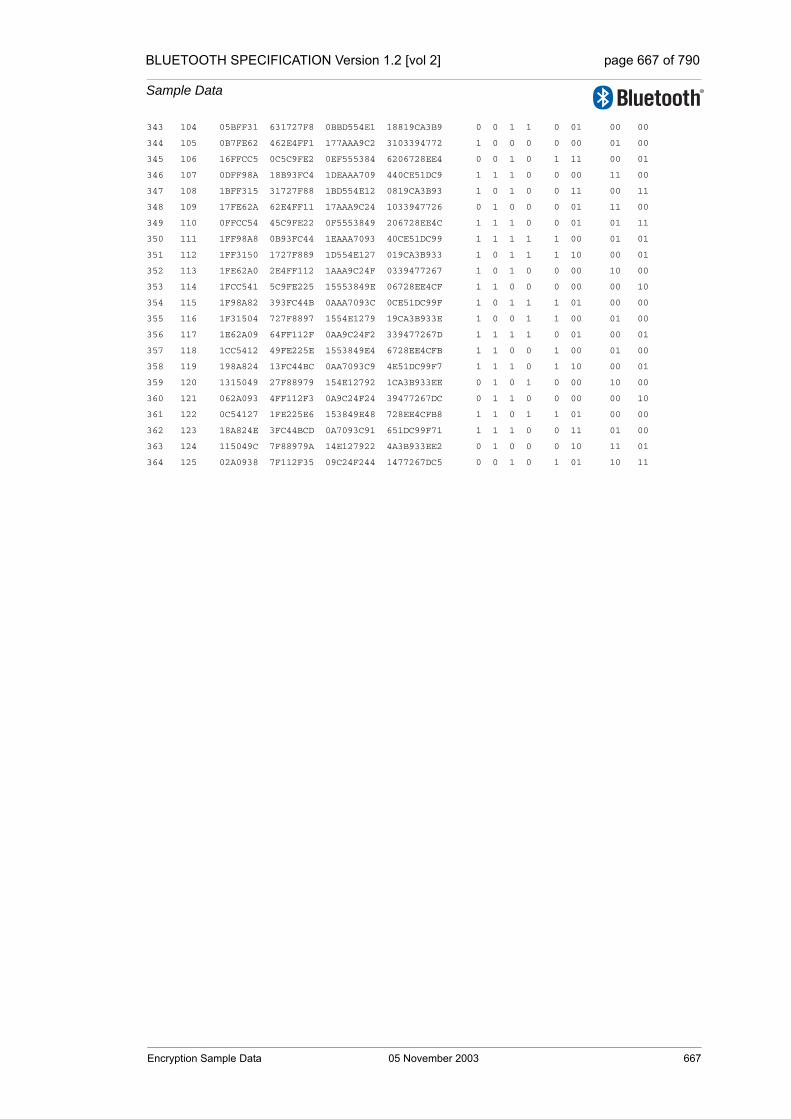
BLUETOOTH SPECIFICATION Version 1.2 [vol 2] page 667 of 790
Sample Data
343 104 05BFF31 631727F8 0BBD554E1 18819CA3B9 0 0 1 1 0 01 00 00
344 105 0B7FE62 462E4FF1 177AAA9C2 3103394772 1 0 0 0 0 00 01 00
345 106 16FFCC5 0C5C9FE2 0EF555384 6206728EE4 0 0 1 0 1 11 00 01
346 107 0DFF98A 18B93FC4 1DEAAA709 440CE51DC9 1 1 1 0 0 00 11 00
347 108 1BFF315 31727F88 1BD554E12 0819CA3B93 1 0 1 0 0 11 00 11
348 109 17FE62A 62E4FF11 17AAA9C24 1033947726 0 1 0 0 0 01 11 00
349 110 0FFCC54 45C9FE22 0F5553849 206728EE4C 1 1 1 0 0 01 01 11
350 111 1FF98A8 0B93FC44 1EAAA7093 40CE51DC99 1 1 1 1 1 00 01 01
351 112 1FF3150 1727F889 1D554E127 019CA3B933 1 0 1 1 1 10 00 01
352 113 1FE62A0 2E4FF112 1AAA9C24F 0339477267 1 0 1 0 0 00 10 00
353 114 1FCC541 5C9FE225 15553849E 06728EE4CF 1 1 0 0 0 00 00 10
354 115 1F98A82 393FC44B 0AAA7093C 0CE51DC99F 1 0 1 1 1 01 00 00
355 116 1F31504 727F8897 1554E1279 19CA3B933E 1 0 0 1 1 00 01 00
356 117 1E62A09 64FF112F 0AA9C24F2 339477267D 1 1 1 1 0 01 00 01
357 118 1CC5412 49FE225E 1553849E4 6728EE4CFB 1 1 0 0 1 00 01 00
358 119 198A824 13FC44BC 0AA7093C9 4E51DC99F7 1 1 1 0 1 10 00 01
359 120 1315049 27F88979 154E12792 1CA3B933EE 0 1 0 1 0 00 10 00
360 121 062A093 4FF112F3 0A9C24F24 39477267DC 0 1 1 0 0 00 00 10
361 122 0C54127 1FE225E6 153849E48 728EE4CFB8 1 1 0 1 1 01 00 00
362 123 18A824E 3FC44BCD 0A7093C91 651DC99F71 1 1 1 0 0 11 01 00
363 124 115049C 7F88979A 14E127922 4A3B933EE2 0 1 0 0 0 10 11 01
364 125 02A0938 7F112F35 09C24F244 1477267DC5 0 0 1 0 1 01 10 11
Encryption Sample Data 05 November 2003 667
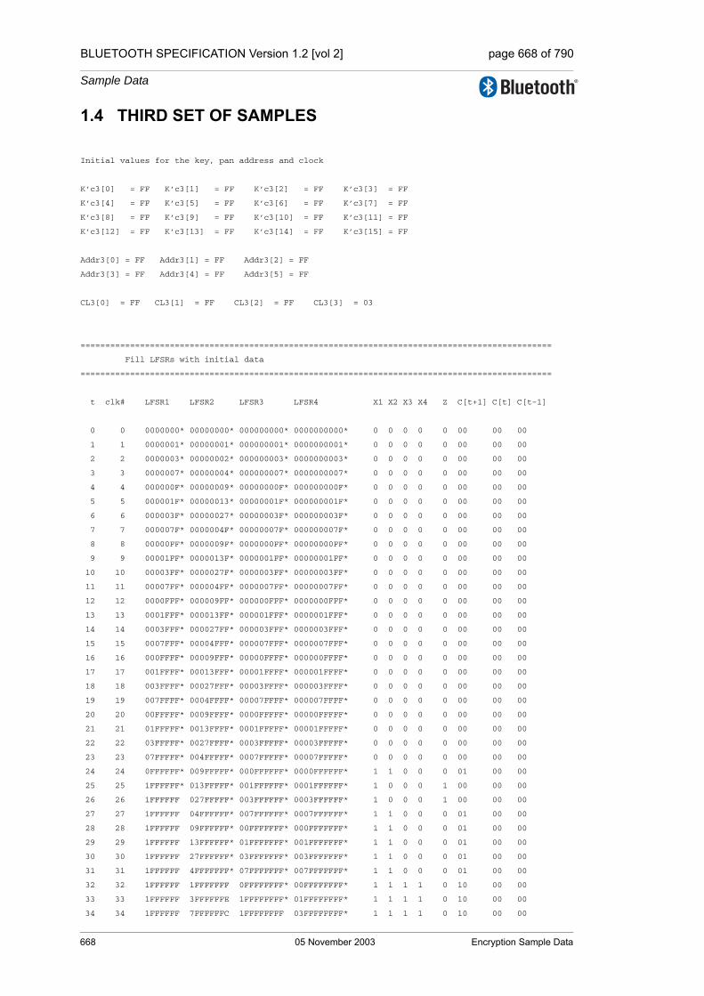
BLUETOOTH SPECIFICATION Version 1.2 [vol 2] page 668 of 790
Sample Data
1.4 THIRD SET OF SAMPLES
Initial values for the key, pan address and clock
K’c3[0] = FF K’c3[1] = FF K’c3[2] = FF K’c3[3] = FF
K’c3[4] = FF K’c3[5] = FF K’c3[6] = FF K’c3[7] = FF
K’c3[8] = FF K’c3[9] = FF K’c3[10] = FF K’c3[11] = FF
K’c3[12] = FF K’c3[13] = FF K’c3[14] = FF K’c3[15] = FF
Addr3[0] = FF Addr3[1] = FF Addr3[2] = FF
Addr3[3] = FF Addr3[4] = FF Addr3[5] = FF
CL3[0] = FF CL3[1] = FF CL3[2] = FF CL3[3] = 03
===============================================================================================
Fill LFSRs with initial data
===============================================================================================
t clk# LFSR1 LFSR2 LFSR3 LFSR4 X1 X2 X3 X4 Z C[t+1] C[t] C[t-1]
0 0 0000000* 00000000* 000000000* 0000000000* 0 0 0 0 0 00 00 00
1 1 0000001* 00000001* 000000001* 0000000001* 0 0 0 0 0 00 00 00
2 2 0000003* 00000002* 000000003* 0000000003* 0 0 0 0 0 00 00 00
3 3 0000007* 00000004* 000000007* 0000000007* 0 0 0 0 0 00 00 00
4 4 000000F* 00000009* 00000000F* 000000000F* 0 0 0 0 0 00 00 00
5 5 000001F* 00000013* 00000001F* 000000001F* 0 0 0 0 0 00 00 00
6 6 000003F* 00000027* 00000003F* 000000003F* 0 0 0 0 0 00 00 00
7 7 000007F* 0000004F* 00000007F* 000000007F* 0 0 0 0 0 00 00 00
8 8 00000FF* 0000009F* 0000000FF* 00000000FF* 0 0 0 0 0 00 00 00
9 9 00001FF* 0000013F* 0000001FF* 00000001FF* 0 0 0 0 0 00 00 00
10 10 00003FF* 0000027F* 0000003FF* 00000003FF* 0 0 0 0 0 00 00 00
11 11 00007FF* 000004FF* 0000007FF* 00000007FF* 0 0 0 0 0 00 00 00
12 12 0000FFF* 000009FF* 000000FFF* 0000000FFF* 0 0 0 0 0 00 00 00
13 13 0001FFF* 000013FF* 000001FFF* 0000001FFF* 0 0 0 0 0 00 00 00
14 14 0003FFF* 000027FF* 000003FFF* 0000003FFF* 0 0 0 0 0 00 00 00
15 15 0007FFF* 00004FFF* 000007FFF* 0000007FFF* 0 0 0 0 0 00 00 00
16 16 000FFFF* 00009FFF* 00000FFFF* 000000FFFF* 0 0 0 0 0 00 00 00
17 17 001FFFF* 00013FFF* 00001FFFF* 000001FFFF* 0 0 0 0 0 00 00 00
18 18 003FFFF* 00027FFF* 00003FFFF* 000003FFFF* 0 0 0 0 0 00 00 00
19 19 007FFFF* 0004FFFF* 00007FFFF* 000007FFFF* 0 0 0 0 0 00 00 00
20 20 00FFFFF* 0009FFFF* 0000FFFFF* 00000FFFFF* 0 0 0 0 0 00 00 00
21 21 01FFFFF* 0013FFFF* 0001FFFFF* 00001FFFFF* 0 0 0 0 0 00 00 00
22 22 03FFFFF* 0027FFFF* 0003FFFFF* 00003FFFFF* 0 0 0 0 0 00 00 00
23 23 07FFFFF* 004FFFFF* 0007FFFFF* 00007FFFFF* 0 0 0 0 0 00 00 00
24 24 0FFFFFF* 009FFFFF* 000FFFFFF* 0000FFFFFF* 1 1 0 0 0 01 00 00
25 25 1FFFFFF* 013FFFFF* 001FFFFFF* 0001FFFFFF* 1 0 0 0 1 00 00 00
26 26 1FFFFFF 027FFFFF* 003FFFFFF* 0003FFFFFF* 1 0 0 0 1 00 00 00
27 27 1FFFFFF 04FFFFFF* 007FFFFFF* 0007FFFFFF* 1 1 0 0 0 01 00 00
28 28 1FFFFFF 09FFFFFF* 00FFFFFFF* 000FFFFFFF* 1 1 0 0 0 01 00 00
29 29 1FFFFFF 13FFFFFF* 01FFFFFFF* 001FFFFFFF* 1 1 0 0 0 01 00 00
30 30 1FFFFFF 27FFFFFF* 03FFFFFFF* 003FFFFFFF* 1 1 0 0 0 01 00 00
31 31 1FFFFFF 4FFFFFFF* 07FFFFFFF* 007FFFFFFF* 1 1 0 0 0 01 00 00
32 32 1FFFFFF 1FFFFFFF 0FFFFFFFF* 00FFFFFFFF* 1 1 1 1 0 10 00 00
33 33 1FFFFFF 3FFFFFFE 1FFFFFFFF* 01FFFFFFFF* 1 1 1 1 0 10 00 00
34 34 1FFFFFF 7FFFFFFC 1FFFFFFFF 03FFFFFFFF* 1 1 1 1 0 10 00 00
668 05 November 2003 Encryption Sample Data

BLUETOOTH SPECIFICATION Version 1.2 [vol 2] page 669 of 790
Sample Data
35 35 1FFFFFF 7FFFFFF9 1FFFFFFFF 07FFFFFFFF* 1 1 1 1 0 10 00 00
36 36 1FFFFFF 7FFFFFF3 1FFFFFFFF 0FFFFFFFFF* 1 1 1 1 0 10 00 00
37 37 1FFFFFF 7FFFFFE7 1FFFFFFFF 1FFFFFFFFF* 1 1 1 1 0 10 00 00
38 38 1FFFFFF 7FFFFFCF 1FFFFFFFF 3FFFFFFFFF* 1 1 1 1 0 10 00 00
39 39 1FFFFFF 7FFFFF9F 1FFFFFFFF 7FFFFFFFFF* 1 1 1 1 0 10 00 00
===============================================================================================
Start clocking Summation Combiner
===============================================================================================
40 1 1FFFFFF 7FFFFF3F 1FFFFFFFF 7FFFFFFFFF 1 1 1 1 0 01 10 00
41 2 1FFFFFF 7FFFFE7F 1FFFFFFFF 7FFFFFFFFF 1 1 1 1 1 10 01 10
42 3 1FFFFFF 7FFFFCFF 1FFFFFFFF 7FFFFFFFFF 1 1 1 1 0 10 10 01
43 4 1FFFFFF 7FFFF9FF 1FFFFFFFF 7FFFFFFFFF 1 1 1 1 0 00 10 10
44 5 1FFFFFF 7FFFF3FF 1FFFFFFFF 7FFFFFFFFF 1 1 1 1 0 11 00 10
45 6 1FFFFFF 7FFFE7FE 1FFFFFFFF 7FFFFFFFFF 1 1 1 1 1 00 11 00
46 7 1FFFFFF 7FFFCFFC 1FFFFFFFF 7FFFFFFFFF 1 1 1 1 0 00 00 11
47 8 1FFFFFF 7FFF9FF9 1FFFFFFFF 7FFFFFFFFF 1 1 1 1 0 10 00 00
48 9 1FFFFFF 7FFF3FF3 1FFFFFFFF 7FFFFFFFFF 1 1 1 1 0 01 10 00
49 10 1FFFFFF 7FFE7FE6 1FFFFFFFF 7FFFFFFFFF 1 1 1 1 1 10 01 10
50 11 1FFFFFE 7FFCFFCC 1FFFFFFFE 7FFFFFFFFF 1 1 1 1 0 10 10 01
51 12 1FFFFFC 7FF9FF99 1FFFFFFFC 7FFFFFFFFF 1 1 1 1 0 00 10 10
52 13 1FFFFF8 7FF3FF33 1FFFFFFF8 7FFFFFFFFF 1 1 1 1 0 11 00 10
53 14 1FFFFF0 7FE7FE67 1FFFFFFF0 7FFFFFFFFF 1 1 1 1 1 00 11 00
54 15 1FFFFE0 7FCFFCCF 1FFFFFFE1 7FFFFFFFFF 1 1 1 1 0 00 00 11
55 16 1FFFFC0 7F9FF99F 1FFFFFFC3 7FFFFFFFFF 1 1 1 1 0 10 00 00
56 17 1FFFF80 7F3FF33E 1FFFFFF87 7FFFFFFFFE 1 0 1 1 1 00 10 00
57 18 1FFFF00 7E7FE67C 1FFFFFF0F 7FFFFFFFFC 1 0 1 1 1 00 00 10
58 19 1FFFE01 7CFFCCF8 1FFFFFE1E 7FFFFFFFF8 1 1 1 1 0 10 00 00
59 20 1FFFC03 79FF99F0 1FFFFFC3C 7FFFFFFFF0 1 1 1 1 0 01 10 00
60 21 1FFF807 73FF33E0 1FFFFF878 7FFFFFFFE1 1 1 1 1 1 10 01 10
61 22 1FFF00F 67FE67C0 1FFFFF0F0 7FFFFFFFC3 1 1 1 1 0 10 10 01
62 23 1FFE01E 4FFCCF80 1FFFFE1E1 7FFFFFFF87 1 1 1 1 0 00 10 10
63 24 1FFC03C 1FF99F00 1FFFFC3C3 7FFFFFFF0F 1 1 1 1 0 11 00 10
64 25 1FF8078 3FF33E01 1FFFF8787 7FFFFFFE1E 1 1 1 1 1 00 11 00
65 26 1FF00F0 7FE67C02 1FFFF0F0F 7FFFFFFC3C 1 1 1 1 0 00 00 11
66 27 1FE01E1 7FCCF805 1FFFE1E1E 7FFFFFF878 1 1 1 1 0 10 00 00
67 28 1FC03C3 7F99F00A 1FFFC3C3C 7FFFFFF0F0 1 1 1 1 0 01 10 00
68 29 1F80787 7F33E015 1FFF87878 7FFFFFE1E1 1 0 1 1 0 10 01 10
69 30 1F00F0F 7E67C02A 1FFF0F0F0 7FFFFFC3C3 1 0 1 1 1 11 10 01
70 31 1E01E1E 7CCF8054 1FFE1E1E1 7FFFFF8787 1 1 1 1 1 01 11 10
71 32 1C03C3C 799F00A9 1FFC3C3C3 7FFFFF0F0F 1 1 1 1 1 01 01 11
72 33 1807878 733E0152 1FF878787 7FFFFE1E1E 1 0 1 1 0 00 01 01
73 34 100F0F0 667C02A5 1FF0F0F0F 7FFFFC3C3C 0 0 1 1 0 10 00 01
74 35 001E1E0 4CF8054B 1FE1E1E1F 7FFFF87878 0 1 1 1 1 00 10 00
75 36 003C3C1 19F00A96 1FC3C3C3F 7FFFF0F0F0 0 1 1 1 1 00 00 10
76 37 0078783 33E0152C 1F878787F 7FFFE1E1E1 0 1 1 1 1 01 00 00
77 38 00F0F07 67C02A59 1F0F0F0FF 7FFFC3C3C3 0 1 1 1 0 11 01 00
78 39 01E1E0E 4F8054B3 1E1E1E1FF 7FFF878787 0 1 1 1 0 11 11 01
79 40 03C3C1C 1F00A966 1C3C3C3FF 7FFF0F0F0F 0 0 1 1 1 11 11 11
80 41 0787838 3E0152CC 1878787FF 7FFE1E1E1E 0 0 1 1 1 11 11 11
81 42 0F0F070 7C02A598 10F0F0FFF 7FFC3C3C3C 1 0 0 1 1 11 11 11
82 43 1E1E0E0 78054B30 01E1E1FFF 7FF8787878 1 0 0 1 1 11 11 11
83 44 1C3C1C0 700A9660 03C3C3FFE 7FF0F0F0F0 1 0 0 1 1 11 11 11
84 45 1878380 60152CC0 078787FFC 7FE1E1E1E0 1 0 0 1 1 11 11 11
85 46 10F0700 402A5980 0F0F0FFF8 7FC3C3C3C0 0 0 1 1 1 11 11 11
86 47 01E0E00 0054B300 1E1E1FFF0 7F87878780 0 0 1 1 1 11 11 11
87 48 03C1C00 00A96601 1C3C3FFE0 7F0F0F0F00 0 1 1 0 1 11 11 11
88 49 0783800 0152CC03 18787FFC0 7E1E1E1E01 0 0 1 0 0 11 11 11
Encryption Sample Data 05 November 2003 669
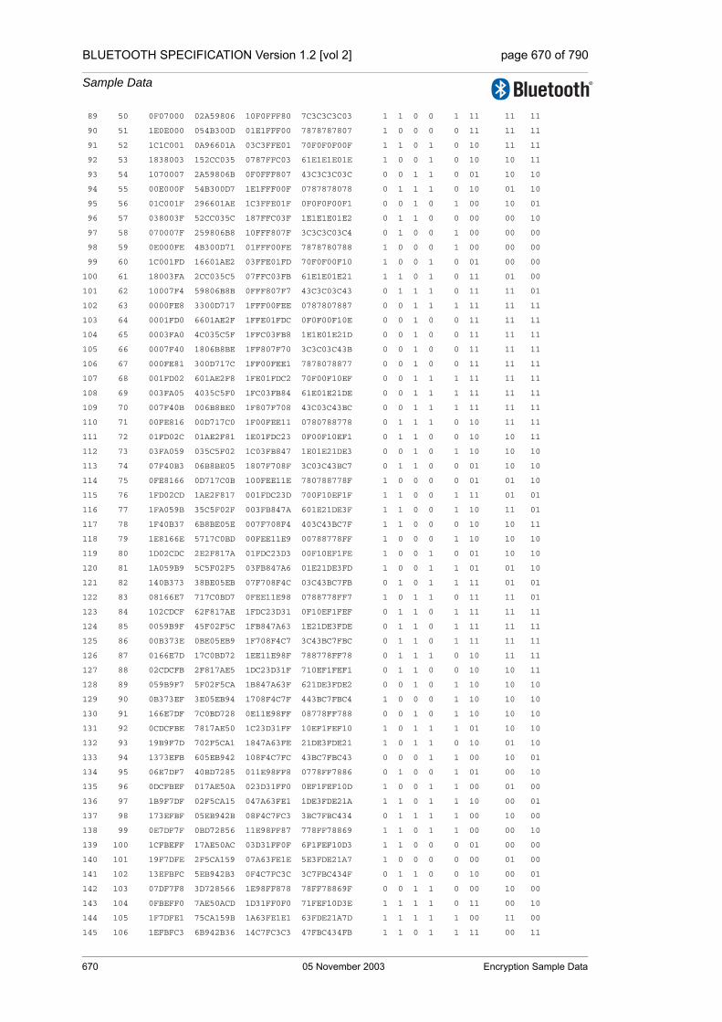
BLUETOOTH SPECIFICATION Version 1.2 [vol 2] page 670 of 790
Sample Data
89 50 0F07000 02A59806 10F0FFF80 7C3C3C3C03 1 1 0 0 1 11 11 11
90 51 1E0E000 054B300D 01E1FFF00 7878787807 1 0 0 0 0 11 11 11
91 52 1C1C001 0A96601A 03C3FFE01 70F0F0F00F 1 1 0 1 0 10 11 11
92 53 1838003 152CC035 0787FFC03 61E1E1E01E 1 0 0 1 0 10 10 11
93 54 1070007 2A59806B 0F0FFF807 43C3C3C03C 0 0 1 1 0 01 10 10
94 55 00E000F 54B300D7 1E1FFF00F 0787878078 0 1 1 1 0 10 01 10
95 56 01C001F 296601AE 1C3FFE01F 0F0F0F00F1 0 0 1 0 1 00 10 01
96 57 038003F 52CC035C 187FFC03F 1E1E1E01E2 0 1 1 0 0 00 00 10
97 58 070007F 259806B8 10FFF807F 3C3C3C03C4 0 1 0 0 1 00 00 00
98 59 0E000FE 4B300D71 01FFF00FE 7878780788 1 0 0 0 1 00 00 00
99 60 1C001FD 16601AE2 03FFE01FD 70F0F00F10 1 0 0 1 0 01 00 00
100 61 18003FA 2CC035C5 07FFC03FB 61E1E01E21 1 1 0 1 0 11 01 00
101 62 10007F4 59806B8B 0FFF807F7 43C3C03C43 0 1 1 1 0 11 11 01
102 63 0000FE8 3300D717 1FFF00FEE 0787807887 0 0 1 1 1 11 11 11
103 64 0001FD0 6601AE2F 1FFE01FDC 0F0F00F10E 0 0 1 0 0 11 11 11
104 65 0003FA0 4C035C5F 1FFC03FB8 1E1E01E21D 0 0 1 0 0 11 11 11
105 66 0007F40 1806B8BE 1FF807F70 3C3C03C43B 0 0 1 0 0 11 11 11
106 67 000FE81 300D717C 1FF00FEE1 7878078877 0 0 1 0 0 11 11 11
107 68 001FD02 601AE2F8 1FE01FDC2 70F00F10EF 0 0 1 1 1 11 11 11
108 69 003FA05 4035C5F0 1FC03FB84 61E01E21DE 0 0 1 1 1 11 11 11
109 70 007F40B 006B8BE0 1F807F708 43C03C43BC 0 0 1 1 1 11 11 11
110 71 00FE816 00D717C0 1F00FEE11 0780788778 0 1 1 1 0 10 11 11
111 72 01FD02C 01AE2F81 1E01FDC23 0F00F10EF1 0 1 1 0 0 10 10 11
112 73 03FA059 035C5F02 1C03FB847 1E01E21DE3 0 0 1 0 1 10 10 10
113 74 07F40B3 06B8BE05 1807F708F 3C03C43BC7 0 1 1 0 0 01 10 10
114 75 0FE8166 0D717C0B 100FEE11E 780788778F 1 0 0 0 0 01 01 10
115 76 1FD02CD 1AE2F817 001FDC23D 700F10EF1F 1 1 0 0 1 11 01 01
116 77 1FA059B 35C5F02F 003FB847A 601E21DE3F 1 1 0 0 1 10 11 01
117 78 1F40B37 6B8BE05E 007F708F4 403C43BC7F 1 1 0 0 0 10 10 11
118 79 1E8166E 5717C0BD 00FEE11E9 00788778FF 1 0 0 0 1 10 10 10
119 80 1D02CDC 2E2F817A 01FDC23D3 00F10EF1FE 1 0 0 1 0 01 10 10
120 81 1A059B9 5C5F02F5 03FB847A6 01E21DE3FD 1 0 0 1 1 01 01 10
121 82 140B373 38BE05EB 07F708F4C 03C43BC7FB 0 1 0 1 1 11 01 01
122 83 08166E7 717C0BD7 0FEE11E98 0788778FF7 1 0 1 1 0 11 11 01
123 84 102CDCF 62F817AE 1FDC23D31 0F10EF1FEF 0 1 1 0 1 11 11 11
124 85 0059B9F 45F02F5C 1FB847A63 1E21DE3FDE 0 1 1 0 1 11 11 11
125 86 00B373E 0BE05EB9 1F708F4C7 3C43BC7FBC 0 1 1 0 1 11 11 11
126 87 0166E7D 17C0BD72 1EE11E98F 788778FF78 0 1 1 1 0 10 11 11
127 88 02CDCFB 2F817AE5 1DC23D31F 710EF1FEF1 0 1 1 0 0 10 10 11
128 89 059B9F7 5F02F5CA 1B847A63F 621DE3FDE2 0 0 1 0 1 10 10 10
129 90 0B373EF 3E05EB94 1708F4C7F 443BC7FBC4 1 0 0 0 1 10 10 10
130 91 166E7DF 7C0BD728 0E11E98FF 08778FF788 0 0 1 0 1 10 10 10
131 92 0CDCFBE 7817AE50 1C23D31FF 10EF1FEF10 1 0 1 1 1 01 10 10
132 93 19B9F7D 702F5CA1 1847A63FE 21DE3FDE21 1 0 1 1 0 10 01 10
133 94 1373EFB 605EB942 108F4C7FC 43BC7FBC43 0 0 0 1 1 00 10 01
134 95 06E7DF7 40BD7285 011E98FF8 0778FF7886 0 1 0 0 1 01 00 10
135 96 0DCFBEF 017AE50A 023D31FF0 0EF1FEF10D 1 0 0 1 1 00 01 00
136 97 1B9F7DF 02F5CA15 047A63FE1 1DE3FDE21A 1 1 0 1 1 10 00 01
137 98 173EFBF 05EB942B 08F4C7FC3 3BC7FBC434 0 1 1 1 1 00 10 00
138 99 0E7DF7F 0BD72856 11E98FF87 778FF78869 1 1 0 1 1 00 00 10
139 100 1CFBEFF 17AE50AC 03D31FF0F 6F1FEF10D3 1 1 0 0 0 01 00 00
140 101 19F7DFE 2F5CA159 07A63FE1E 5E3FDE21A7 1 0 0 0 0 00 01 00
141 102 13EFBFC 5EB942B3 0F4C7FC3C 3C7FBC434F 0 1 1 0 0 10 00 01
142 103 07DF7F8 3D728566 1E98FF878 78FF78869F 0 0 1 1 0 00 10 00
143 104 0FBEFF0 7AE50ACD 1D31FF0F0 71FEF10D3E 1 1 1 1 0 11 00 10
144 105 1F7DFE1 75CA159B 1A63FE1E1 63FDE21A7D 1 1 1 1 1 00 11 00
145 106 1EFBFC3 6B942B36 14C7FC3C3 47FBC434FB 1 1 0 1 1 11 00 11
670 05 November 2003 Encryption Sample Data

BLUETOOTH SPECIFICATION Version 1.2 [vol 2] page 671 of 790
Sample Data
146 107 1DF7F86 5728566D 098FF8786 0FF78869F7 1 0 1 1 0 00 11 00
147 108 1BEFF0C 2E50ACDB 131FF0F0C 1FEF10D3EF 1 0 0 1 0 11 00 11
148 109 17DFE19 5CA159B6 063FE1E19 3FDE21A7DF 0 1 0 1 1 01 11 00
149 110 0FBFC33 3942B36D 0C7FC3C32 7FBC434FBF 1 0 1 1 0 01 01 11
150 111 1F7F866 728566DB 18FF87865 7F78869F7E 1 1 1 0 0 00 01 01
151 112 1EFF0CC 650ACDB6 11FF0F0CB 7EF10D3EFC 1 0 0 1 0 10 00 01
152 113 1DFE199 4A159B6D 03FE1E196 7DE21A7DF9 1 0 0 1 0 00 10 00
153 114 1BFC333 142B36DB 07FC3C32C 7BC434FBF3 1 0 0 1 0 00 00 10
154 115 17F8666 28566DB6 0FF878659 778869F7E6 0 0 1 1 0 01 00 00
155 116 0FF0CCC 50ACDB6D 1FF0F0CB3 6F10D3EFCC 1 1 1 0 0 11 01 00
156 117 1FE1999 2159B6DA 1FE1E1966 5E21A7DF99 1 0 1 0 1 10 11 01
157 118 1FC3332 42B36DB5 1FC3C32CC 3C434FBF33 1 1 1 0 1 10 10 11
158 119 1F86664 0566DB6B 1F8786599 78869F7E67 1 0 1 1 1 01 10 10
159 120 1F0CCC8 0ACDB6D6 1F0F0CB33 710D3EFCCE 1 1 1 0 0 10 01 10
160 121 1E19991 159B6DAC 1E1E19666 621A7DF99D 1 1 1 0 1 11 10 01
161 122 1C33323 2B36DB58 1C3C32CCC 4434FBF33B 1 0 1 0 1 00 11 10
162 123 1866647 566DB6B0 187865999 0869F7E676 1 0 1 0 0 11 00 11
163 124 10CCC8F 2CDB6D60 10F0CB333 10D3EFCCEC 0 1 0 1 1 01 11 00
164 125 019991E 59B6DAC0 01E196666 21A7DF99D9 0 1 0 1 1 10 01 11
165 126 033323C 336DB580 03C32CCCD 434FBF33B3 0 0 0 0 0 00 10 01
166 127 0666478 66DB6B01 07865999A 069F7E6766 0 1 0 1 0 00 00 10
167 128 0CCC8F0 4DB6D603 0F0CB3334 0D3EFCCECD 1 1 1 0 1 01 00 00
168 129 19991E1 1B6DAC07 1E1966669 1A7DF99D9B 1 0 1 0 1 00 01 00
169 130 13323C3 36DB580E 1C32CCCD3 34FBF33B37 0 1 1 1 1 10 00 01
170 131 0664786 6DB6B01C 1865999A7 69F7E6766F 0 1 1 1 1 00 10 00
171 132 0CC8F0D 5B6D6039 10CB3334F 53EFCCECDF 1 0 0 1 0 00 00 10
172 133 1991E1A 36DAC073 01966669E 27DF99D9BF 1 1 0 1 1 01 00 00
173 134 1323C35 6DB580E6 032CCCD3C 4FBF33B37E 0 1 0 1 1 00 01 00
174 135 064786A 5B6B01CD 065999A78 1F7E6766FC 0 0 0 0 0 11 00 01
175 136 0C8F0D5 36D6039B 0CB3334F0 3EFCCECDF9 1 1 1 1 1 00 11 00
176 137 191E1AA 6DAC0737 1966669E1 7DF99D9BF3 1 1 1 1 0 00 00 11
177 138 123C354 5B580E6E 12CCCD3C3 7BF33B37E7 0 0 0 1 1 00 00 00
178 139 04786A9 36B01CDC 05999A787 77E6766FCE 0 1 0 1 0 01 00 00
179 140 08F0D53 6D6039B8 0B3334F0E 6FCCECDF9C 1 0 1 1 0 11 01 00
180 141 11E1AA6 5AC07370 166669E1D 5F99D9BF38 0 1 0 1 1 10 11 01
181 142 03C354C 3580E6E0 0CCCD3C3A 3F33B37E70 0 1 1 0 0 10 10 11
182 143 0786A99 6B01CDC0 1999A7875 7E6766FCE1 0 0 1 0 1 10 10 10
183 144 0F0D533 56039B81 13334F0EB 7CCECDF9C2 1 0 0 1 0 01 10 10
184 145 1E1AA66 2C073703 06669E1D6 799D9BF385 1 0 0 1 1 01 01 10
185 146 1C354CC 580E6E06 0CCD3C3AC 733B37E70B 1 0 1 0 1 11 01 01
186 147 186A998 301CDC0C 199A78759 66766FCE17 1 0 1 0 1 10 11 01
187 148 10D5331 6039B818 1334F0EB2 4CECDF9C2F 0 0 0 1 1 01 10 11
188 149 01AA662 40737031 0669E1D65 19D9BF385E 0 0 0 1 0 01 01 10
189 150 0354CC5 00E6E063 0CD3C3ACB 33B37E70BD 0 1 1 1 0 00 01 01
190 151 06A998A 01CDC0C6 19A787596 6766FCE17B 0 1 1 0 0 10 00 01
191 152 0D53315 039B818C 134F0EB2C 4ECDF9C2F6 1 1 0 1 1 00 10 00
192 153 1AA662A 07370318 069E1D659 1D9BF385ED 1 0 0 1 0 00 00 10
193 154 154CC54 0E6E0630 0D3C3ACB3 3B37E70BDB 0 0 1 0 1 00 00 00
194 155 0A998A8 1CDC0C60 1A7875967 766FCE17B6 1 1 1 0 1 01 00 00
195 156 1533151 39B818C0 14F0EB2CE 6CDF9C2F6C 0 1 0 1 1 00 01 00
196 157 0A662A3 73703180 09E1D659D 59BF385ED8 1 0 1 1 1 10 00 01
197 158 14CC547 66E06301 13C3ACB3A 337E70BDB0 0 1 0 0 1 11 10 00
198 159 0998A8E 4DC0C602 078759675 66FCE17B61 1 1 0 1 0 01 11 10
199 160 133151D 1B818C05 0F0EB2CEB 4DF9C2F6C2 0 1 1 1 0 01 01 11
200 161 0662A3B 3703180B 1E1D659D6 1BF385ED85 0 0 1 1 1 11 01 01
201 162 0CC5477 6E063017 1C3ACB3AC 37E70BDB0B 1 0 1 1 0 11 11 01
202 163 198A8EF 5C0C602F 187596759 6FCE17B617 1 0 1 1 0 10 11 11
Encryption Sample Data 05 November 2003 671
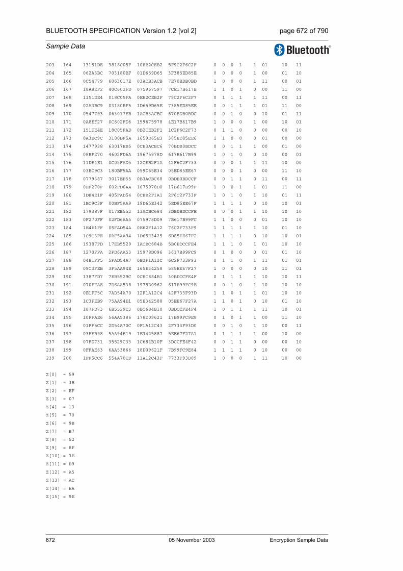
BLUETOOTH SPECIFICATION Version 1.2 [vol 2] page 672 of 790
Sample Data
203 164 13151DE 3818C05F 10EB2CEB2 5F9C2F6C2F 0 0 0 1 1 01 10 11
204 165 062A3BC 703180BF 01D659D65 3F385ED85E 0 0 0 0 1 00 01 10
205 166 0C54779 6063017E 03ACB3ACB 7E70BDB0BD 1 0 0 0 1 11 00 01
206 167 18A8EF2 40C602FD 075967597 7CE17B617B 1 1 0 1 0 00 11 00
207 168 1151DE4 018C05FA 0EB2CEB2F 79C2F6C2F7 0 1 1 1 1 11 00 11
208 169 02A3BC9 03180BF5 1D659D65E 7385ED85EE 0 0 1 1 1 01 11 00
209 170 0547793 063017EB 1ACB3ACBC 670BDB0BDC 0 0 1 0 0 10 01 11
210 171 0A8EF27 0C602FD6 159675978 4E17B617B9 1 0 0 0 1 00 10 01
211 172 151DE4E 18C05FAD 0B2CEB2F1 1C2F6C2F73 0 1 1 0 0 00 00 10
212 173 0A3BC9C 3180BF5A 1659D65E3 385ED85EE6 1 1 0 0 0 01 00 00
213 174 1477938 63017EB5 0CB3ACBC6 70BDB0BDCC 0 0 1 1 1 00 01 00
214 175 08EF270 4602FD6A 19675978D 617B617B99 1 0 1 0 0 10 00 01
215 176 11DE4E1 0C05FAD5 12CEB2F1A 42F6C2F733 0 0 0 1 1 11 10 00
216 177 03BC9C3 180BF5AA 059D65E34 05ED85EE67 0 0 0 1 0 00 11 10
217 178 0779387 3017EB55 0B3ACBC68 0BDB0BDCCF 0 0 1 1 0 11 00 11
218 179 0EF270F 602FD6AA 1675978D0 17B617B99F 1 0 0 1 1 01 11 00
219 180 1DE4E1F 405FAD54 0CEB2F1A1 2F6C2F733F 1 0 1 0 1 10 01 11
220 181 1BC9C3F 00BF5AA9 19D65E342 5ED85EE67F 1 1 1 1 0 10 10 01
221 182 179387F 017EB552 13ACBC684 3DB0BDCCFE 0 0 0 1 1 10 10 10
222 183 0F270FF 02FD6AA5 075978D09 7B617B99FC 1 1 0 0 0 01 10 10
223 184 1E4E1FF 05FAD54A 0EB2F1A12 76C2F733F9 1 1 1 1 1 10 01 10
224 185 1C9C3FE 0BF5AA94 1D65E3425 6D85EE67F2 1 1 1 1 0 10 10 01
225 186 19387FD 17EB5529 1ACBC684B 5B0BDCCFE4 1 1 1 0 1 01 10 10
226 187 1270FFA 2FD6AA53 15978D096 3617B99FC9 0 1 0 0 0 01 01 10
227 188 04E1FF5 5FAD54A7 0B2F1A12C 6C2F733F93 0 1 1 0 1 11 01 01
228 189 09C3FEB 3F5AA94E 165E34258 585EE67F27 1 0 0 0 0 10 11 01
229 190 1387FD7 7EB5529C 0CBC684B1 30BDCCFE4F 0 1 1 1 1 10 10 11
230 191 070FFAE 7D6AA538 1978D0962 617B99FC9E 0 0 1 0 1 10 10 10
231 192 0E1FF5C 7AD54A70 12F1A12C4 42F733F93D 1 1 0 1 1 01 10 10
232 193 1C3FEB9 75AA94E1 05E342588 05EE67F27A 1 1 0 1 0 10 01 10
233 194 187FD73 6B5529C3 0BC684B10 0BDCCFE4F4 1 0 1 1 1 11 10 01
234 195 10FFAE6 56AA5386 178D09621 17B99FC9E8 0 1 0 1 1 00 11 10
235 196 01FF5CC 2D54A70C 0F1A12C43 2F733F93D0 0 0 1 0 1 10 00 11
236 197 03FEB98 5AA94E19 1E3425887 5EE67F27A1 0 1 1 1 1 00 10 00
237 198 07FD731 35529C33 1C684B10F 3DCCFE4F42 0 0 1 1 0 00 00 10
238 199 0FFAE63 6AA53866 18D09621F 7B99FC9E84 1 1 1 1 0 10 00 00
239 200 1FF5CC6 554A70CD 11A12C43F 7733F93D09 1 0 0 0 1 11 10 00
Z[0] = 59
Z[1] = 3B
Z[2] = EF
Z[3] = 07
Z[4] = 13
Z[5] = 70
Z[6] = 9B
Z[7] = B7
Z[8] = 52
Z[9] = 8F
Z[10] = 3E
Z[11] = B9
Z[12] = A5
Z[13] = AC
Z[14] = EA
Z[15] = 9E
672 05 November 2003 Encryption Sample Data
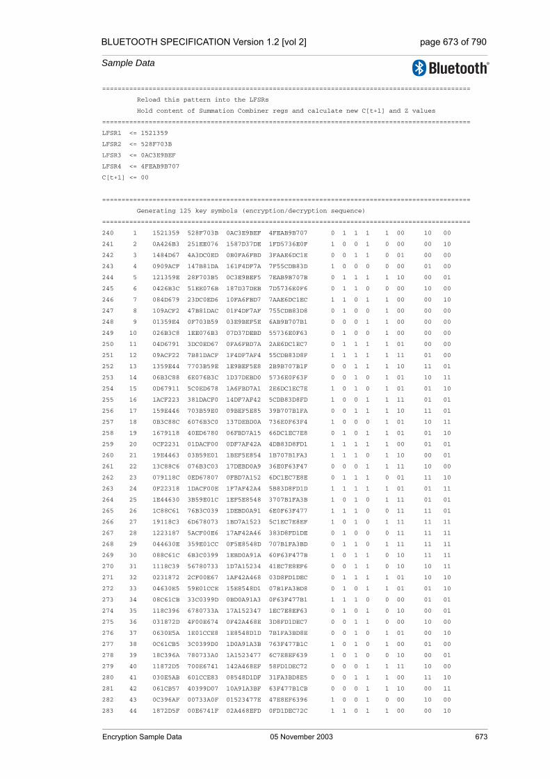
BLUETOOTH SPECIFICATION Version 1.2 [vol 2] page 673 of 790
Sample Data
===============================================================================================
Reload this pattern into the LFSRs
Hold content of Summation Combiner regs and calculate new C[t+1] and Z values
===============================================================================================
LFSR1 <= 1521359
LFSR2 <= 528F703B
LFSR3 <= 0AC3E9BEF
LFSR4 <= 4FEAB9B707
C[t+1] <= 00
===============================================================================================
Generating 125 key symbols (encryption/decryption sequence)
===============================================================================================
240 1 1521359 528F703B 0AC3E9BEF 4FEAB9B707 0 1 1 1 1 00 10 00
241 2 0A426B3 251EE076 1587D37DE 1FD5736E0F 1 0 0 1 0 00 00 10
242 3 1484D67 4A3DC0ED 0B0FA6FBD 3FAAE6DC1E 0 0 1 1 0 01 00 00
243 4 0909ACF 147B81DA 161F4DF7A 7F55CDB83D 1 0 0 0 0 00 01 00
244 5 121359E 28F703B5 0C3E9BEF5 7EAB9B707B 0 1 1 1 1 10 00 01
245 6 0426B3C 51EE076B 187D37DEB 7D5736E0F6 0 1 1 0 0 00 10 00
246 7 084D679 23DC0ED6 10FA6FBD7 7AAE6DC1EC 1 1 0 1 1 00 00 10
247 8 109ACF2 47B81DAC 01F4DF7AF 755CDB83D8 0 1 0 0 1 00 00 00
248 9 01359E4 0F703B59 03E9BEF5E 6AB9B707B1 0 0 0 1 1 00 00 00
249 10 026B3C8 1EE076B3 07D37DEBD 55736E0F63 0 1 0 0 1 00 00 00
250 11 04D6791 3DC0ED67 0FA6FBD7A 2AE6DC1EC7 0 1 1 1 1 01 00 00
251 12 09ACF22 7B81DACF 1F4DF7AF4 55CDB83D8F 1 1 1 1 1 11 01 00
252 13 1359E44 7703B59E 1E9BEF5E8 2B9B707B1F 0 0 1 1 1 10 11 01
253 14 06B3C88 6E076B3C 1D37DEBD0 5736E0F63F 0 0 1 0 1 01 10 11
254 15 0D67911 5C0ED678 1A6FBD7A1 2E6DC1EC7E 1 0 1 0 1 01 01 10
255 16 1ACF223 381DACF0 14DF7AF42 5CDB83D8FD 1 0 0 1 1 11 01 01
256 17 159E446 703B59E0 09BEF5E85 39B707B1FA 0 0 1 1 1 10 11 01
257 18 0B3C88C 6076B3C0 137DEBD0A 736E0F63F4 1 0 0 0 1 01 10 11
258 19 1679118 40ED6780 06FBD7A15 66DC1EC7E8 0 1 0 1 1 01 01 10
259 20 0CF2231 01DACF00 0DF7AF42A 4DB83D8FD1 1 1 1 1 1 00 01 01
260 21 19E4463 03B59E01 1BEF5E854 1B707B1FA3 1 1 1 0 1 10 00 01
261 22 13C88C6 076B3C03 17DEBD0A9 36E0F63F47 0 0 0 1 1 11 10 00
262 23 079118C 0ED67807 0FBD7A152 6DC1EC7E8E 0 1 1 1 0 01 11 10
263 24 0F22318 1DACF00E 1F7AF42A4 5B83D8FD1D 1 1 1 1 1 01 01 11
264 25 1E44630 3B59E01C 1EF5E8548 3707B1FA3B 1 0 1 0 1 11 01 01
265 26 1C88C61 76B3C039 1DEBD0A91 6E0F63F477 1 1 1 0 0 11 11 01
266 27 19118C3 6D678073 1BD7A1523 5C1EC7E8EF 1 0 1 0 1 11 11 11
267 28 1223187 5ACF00E6 17AF42A46 383D8FD1DE 0 1 0 0 0 11 11 11
268 29 044630E 359E01CC 0F5E8548D 707B1FA3BD 0 1 1 0 1 11 11 11
269 30 088C61C 6B3C0399 1EBD0A91A 60F63F477B 1 0 1 1 0 10 11 11
270 31 1118C39 56780733 1D7A15234 41EC7E8EF6 0 0 1 1 0 10 10 11
271 32 0231872 2CF00E67 1AF42A468 03D8FD1DEC 0 1 1 1 1 01 10 10
272 33 04630E5 59E01CCE 15E8548D1 07B1FA3BD8 0 1 0 1 1 01 01 10
273 34 08C61CB 33C0399D 0BD0A91A3 0F63F477B1 1 1 1 0 0 00 01 01
274 35 118C396 6780733A 17A152347 1EC7E8EF63 0 1 0 1 0 10 00 01
275 36 031872D 4F00E674 0F42A468E 3D8FD1DEC7 0 0 1 1 0 00 10 00
276 37 0630E5A 1E01CCE8 1E8548D1D 7B1FA3BD8E 0 0 1 0 1 01 00 10
277 38 0C61CB5 3C0399D0 1D0A91A3B 763F477B1C 1 0 1 0 1 00 01 00
278 39 18C396A 780733A0 1A1523477 6C7E8EF639 1 0 1 0 0 10 00 01
279 40 11872D5 700E6741 142A468EF 58FD1DEC72 0 0 0 1 1 11 10 00
280 41 030E5AB 601CCE83 08548D1DF 31FA3BD8E5 0 0 1 1 1 00 11 10
281 42 061CB57 40399D07 10A91A3BF 63F477B1CB 0 0 0 1 1 10 00 11
282 43 0C396AF 00733A0F 01523477E 47E8EF6396 1 0 0 1 0 00 10 00
283 44 1872D5F 00E6741F 02A468EFD 0FD1DEC72C 1 1 0 1 1 00 00 10
Encryption Sample Data 05 November 2003 673

BLUETOOTH SPECIFICATION Version 1.2 [vol 2] page 674 of 790
Sample Data
284 45 10E5ABE 01CCE83F 0548D1DFA 1FA3BD8E58 0 1 0 1 0 01 00 00
285 46 01CB57C 0399D07F 0A91A3BF4 3F477B1CB0 0 1 1 0 1 00 01 00
286 47 0396AF9 0733A0FE 1523477E9 7E8EF63961 0 0 0 1 1 11 00 01
287 48 072D5F3 0E6741FD 0A468EFD2 7D1DEC72C3 0 0 1 0 0 01 11 00
288 49 0E5ABE7 1CCE83FA 148D1DFA4 7A3BD8E587 1 1 0 0 1 10 01 11
289 50 1CB57CE 399D07F4 091A3BF49 7477B1CB0F 1 1 1 0 1 11 10 01
290 51 196AF9D 733A0FE9 123477E92 68EF63961E 1 0 0 1 1 00 11 10
291 52 12D5F3B 66741FD2 0468EFD25 51DEC72C3C 0 0 0 1 1 10 00 11
292 53 05ABE77 4CE83FA4 08D1DFA4B 23BD8E5879 0 1 1 1 1 00 10 00
293 54 0B57CEE 19D07F49 11A3BF496 477B1CB0F2 1 1 0 0 0 00 00 10
294 55 16AF9DC 33A0FE92 03477E92C 0EF63961E4 0 1 0 1 0 01 00 00
295 56 0D5F3B8 6741FD25 068EFD259 1DEC72C3C9 1 0 0 1 1 00 01 00
296 57 1ABE771 4E83FA4B 0D1DFA4B3 3BD8E58793 1 1 1 1 0 01 00 01
297 58 157CEE2 1D07F496 1A3BF4967 77B1CB0F26 0 0 1 1 1 00 01 00
298 59 0AF9DC5 3A0FE92D 1477E92CE 6F63961E4D 1 0 0 0 1 11 00 01
299 60 15F3B8B 741FD25A 08EFD259C 5EC72C3C9B 0 0 1 1 1 01 11 00
300 61 0BE7716 683FA4B4 11DFA4B39 3D8E587937 1 0 0 1 1 10 01 11
301 62 17CEE2D 507F4968 03BF49672 7B1CB0F26E 0 0 0 0 0 00 10 01
302 63 0F9DC5B 20FE92D0 077E92CE4 763961E4DC 1 1 0 0 0 00 00 10
303 64 1F3B8B6 41FD25A0 0EFD259C9 6C72C3C9B9 1 1 1 0 1 01 00 00
304 65 1E7716D 03FA4B40 1DFA4B393 58E5879373 1 1 1 1 1 11 01 00
305 66 1CEE2DB 07F49680 1BF496727 31CB0F26E6 1 1 1 1 1 11 11 01
306 67 19DC5B7 0FE92D00 17E92CE4E 63961E4DCD 1 1 0 1 0 10 11 11
307 68 13B8B6F 1FD25A00 0FD259C9C 472C3C9B9A 0 1 1 0 0 10 10 11
308 69 07716DF 3FA4B400 1FA4B3938 0E58793735 0 1 1 0 0 01 10 10
309 70 0EE2DBF 7F496800 1F4967271 1CB0F26E6A 1 0 1 1 0 10 01 10
310 71 1DC5B7F 7E92D000 1E92CE4E2 3961E4DCD4 1 1 1 0 1 11 10 01
311 72 1B8B6FF 7D25A001 1D259C9C4 72C3C9B9A9 1 0 1 1 0 01 11 10
312 73 1716DFF 7A4B4002 1A4B39389 6587937352 0 0 1 1 1 10 01 11
313 74 0E2DBFF 74968005 149672713 4B0F26E6A5 1 1 0 0 0 11 10 01
314 75 1C5B7FE 692D000B 092CE4E26 161E4DCD4B 1 0 1 0 1 00 11 10
315 76 18B6FFC 525A0017 1259C9C4D 2C3C9B9A96 1 0 0 0 1 10 00 11
316 77 116DFF8 24B4002F 04B39389B 587937352C 0 1 0 0 1 11 10 00
317 78 02DBFF1 4968005F 096727136 30F26E6A58 0 0 1 1 1 00 11 10
318 79 05B7FE3 12D000BF 12CE4E26C 61E4DCD4B1 0 1 0 1 0 11 00 11
319 80 0B6FFC7 25A0017F 059C9C4D8 43C9B9A963 1 1 0 1 0 00 11 00
320 81 16DFF8E 4B4002FF 0B39389B1 07937352C6 0 0 1 1 0 11 00 11
321 82 0DBFF1C 168005FF 167271363 0F26E6A58C 1 1 0 0 1 01 11 00
322 83 1B7FE38 2D000BFF 0CE4E26C7 1E4DCD4B18 1 0 1 0 1 10 01 11
323 84 16FFC70 5A0017FF 19C9C4D8F 3C9B9A9631 0 0 1 1 0 11 10 01
324 85 0DFF8E1 34002FFF 139389B1E 7937352C62 1 0 0 0 0 00 11 10
325 86 1BFF1C3 68005FFF 07271363D 726E6A58C4 1 0 0 0 1 10 00 11
326 87 17FE387 5000BFFE 0E4E26C7B 64DCD4B188 0 0 1 1 0 00 10 00
327 88 0FFC70F 20017FFD 1C9C4D8F6 49B9A96311 1 0 1 1 1 00 00 10
328 89 1FF8E1F 4002FFFB 19389B1ED 137352C623 1 0 1 0 0 01 00 00
329 90 1FF1C3F 0005FFF7 1271363DB 26E6A58C46 1 0 0 1 1 00 01 00
330 91 1FE387F 000BFFEE 04E26C7B6 4DCD4B188C 1 0 0 1 0 10 00 01
331 92 1FC70FF 0017FFDC 09C4D8F6D 1B9A963118 1 0 1 1 1 00 10 00
332 93 1F8E1FF 002FFFB8 1389B1EDA 37352C6231 1 0 0 0 1 01 00 10
333 94 1F1C3FF 005FFF70 071363DB4 6E6A58C462 1 0 0 0 0 00 01 00
334 95 1E387FE 00BFFEE0 0E26C7B68 5CD4B188C5 1 1 1 1 0 01 00 01
335 96 1C70FFC 017FFDC1 1C4D8F6D1 39A963118A 1 0 1 1 0 11 01 00
336 97 18E1FF9 02FFFB82 189B1EDA2 7352C62315 1 1 1 0 0 11 11 01
337 98 11C3FF2 05FFF705 11363DB45 66A58C462B 0 1 0 1 1 11 11 11
338 99 0387FE4 0BFFEE0A 026C7B68B 4D4B188C56 0 1 0 0 0 11 11 11
339 100 070FFC9 17FFDC15 04D8F6D16 1A963118AD 0 1 0 1 1 11 11 11
340 101 0E1FF92 2FFFB82B 09B1EDA2C 352C62315A 1 1 1 0 0 10 11 11
674 05 November 2003 Encryption Sample Data
BLUETOOTH SPECIFICATION Version 1.2 [vol 2] page 675 of 790
Sample Data
341 102 1C3FF24 5FFF7057 1363DB458 6A58C462B4 1 1 0 0 0 10 10 11
342 103 187FE48 3FFEE0AE 06C7B68B0 54B188C569 1 1 0 1 1 01 10 10
343 104 10FFC90 7FFDC15C 0D8F6D161 2963118AD2 0 1 1 0 1 01 01 10
344 105 01FF920 7FFB82B9 1B1EDA2C2 52C62315A5 0 1 1 1 0 00 01 01
345 106 03FF240 7FF70573 163DB4584 258C462B4B 0 1 0 1 0 10 00 01
346 107 07FE481 7FEE0AE6 0C7B68B08 4B188C5696 0 1 1 0 0 00 10 00
347 108 0FFC902 7FDC15CD 18F6D1610 163118AD2D 1 1 1 0 1 00 00 10
348 109 1FF9204 7FB82B9A 11EDA2C20 2C62315A5B 1 1 0 0 0 01 00 00
349 110 1FF2408 7F705735 03DB45841 58C462B4B6 1 0 0 1 1 00 01 00
350 111 1FE4810 7EE0AE6B 07B68B082 3188C5696C 1 1 0 1 1 10 00 01
351 112 1FC9021 7DC15CD6 0F6D16105 63118AD2D8 1 1 1 0 1 00 10 00
352 113 1F92042 7B82B9AD 1EDA2C20B 462315A5B0 1 1 1 0 1 00 00 10
353 114 1F24084 7705735A 1DB458416 0C462B4B61 1 0 1 0 0 01 00 00
354 115 1E48108 6E0AE6B5 1B68B082C 188C5696C3 1 0 1 1 0 11 01 00
355 116 1C90211 5C15CD6A 16D161059 3118AD2D86 1 0 0 0 0 10 11 01
356 117 1920422 382B9AD5 0DA2C20B3 62315A5B0D 1 0 1 0 0 10 10 11
357 118 1240845 705735AA 1B4584167 4462B4B61A 0 0 1 0 1 10 10 10
358 119 048108A 60AE6B55 168B082CF 08C5696C34 0 1 0 1 0 01 10 10
359 120 0902114 415CD6AB 0D161059E 118AD2D869 1 0 1 1 0 10 01 10
360 121 1204228 02B9AD56 1A2C20B3D 2315A5B0D2 0 1 1 0 0 11 10 01
361 122 0408451 05735AAD 14584167B 462B4B61A4 0 0 0 0 1 11 11 10
362 123 08108A2 0AE6B55B 08B082CF7 0C5696C348 1 1 1 0 0 10 11 11
363 124 1021144 15CD6AB6 1161059EF 18AD2D8690 0 1 0 1 0 10 10 11
364 125 0042289 2B9AD56C 02C20B3DE 315A5B0D20 0 1 0 0 1 10 10 10
Encryption Sample Data 05 November 2003 675

BLUETOOTH SPECIFICATION Version 1.2 [vol 2] page 676 of 790
Sample Data
1.5 FOURTH SET OF SAMPLES
Initial values for the key, pan address and clock
K’c4[0] = 21 K’c4[1] = 87 K’c4[2] = F0 K’c4[3] = 4A
K’c4[4] = BA K’c4[5] = 90 K’c4[6] = 31 K’c4[7] = D0
K’c4[8] = 78 K’c4[9] = 0D K’c4[10] = 4C K’c4[11] = 53
K’c4[12] = E0 K’c4[13] = 15 K’c4[14] = 3A K’c4[15] = 63
Addr4[0] = 2C Addr4[1] = 7F Addr4[2] = 94
Addr4[3] = 56 Addr4[4] = 0F Addr4[5] = 1B
CL4[0] = 5F CL4[1] = 1A CL4[2] = 00 CL4[3] = 02
===============================================================================================
Fill LFSRs with initial data
===============================================================================================
t clk# LFSR1 LFSR2 LFSR3 LFSR4 X1 X2 X3 X4 Z C[t+1] C[t] C[t-1]
0 0 0000000* 00000000* 000000000* 0000000000* 0 0 0 0 0 00 00 00
1 1 0000000* 00000001* 000000001* 0000000001* 0 0 0 0 0 00 00 00
2 2 0000001* 00000002* 000000002* 0000000003* 0 0 0 0 0 00 00 00
3 3 0000002* 00000004* 000000004* 0000000007* 0 0 0 0 0 00 00 00
4 4 0000004* 00000009* 000000008* 000000000F* 0 0 0 0 0 00 00 00
5 5 0000008* 00000013* 000000010* 000000001E* 0 0 0 0 0 00 00 00
6 6 0000010* 00000027* 000000021* 000000003D* 0 0 0 0 0 00 00 00
7 7 0000021* 0000004F* 000000043* 000000007A* 0 0 0 0 0 00 00 00
8 8 0000042* 0000009F* 000000087* 00000000F4* 0 0 0 0 0 00 00 00
9 9 0000084* 0000013F* 00000010F* 00000001E9* 0 0 0 0 0 00 00 00
10 10 0000108* 0000027F* 00000021F* 00000003D2* 0 0 0 0 0 00 00 00
11 11 0000211* 000004FE* 00000043E* 00000007A5* 0 0 0 0 0 00 00 00
12 12 0000422* 000009FC* 00000087C* 0000000F4A* 0 0 0 0 0 00 00 00
13 13 0000845* 000013F8* 0000010F8* 0000001E94* 0 0 0 0 0 00 00 00
14 14 000108B* 000027F0* 0000021F1* 0000003D29* 0 0 0 0 0 00 00 00
15 15 0002117* 00004FE1* 0000043E3* 0000007A52* 0 0 0 0 0 00 00 00
16 16 000422E* 00009FC2* 0000087C6* 000000F4A4* 0 0 0 0 0 00 00 00
17 17 000845D* 00013F84* 000010F8C* 000001E948* 0 0 0 0 0 00 00 00
18 18 00108BA* 00027F08* 000021F18* 000003D290* 0 0 0 0 0 00 00 00
19 19 0021174* 0004FE10* 000043E30* 000007A520* 0 0 0 0 0 00 00 00
20 20 00422E8* 0009FC21* 000087C61* 00000F4A41* 0 0 0 0 0 00 00 00
21 21 00845D1* 0013F842* 00010F8C3* 00001E9482* 0 0 0 0 0 00 00 00
22 22 0108BA3* 0027F084* 00021F186* 00003D2905* 0 0 0 0 0 00 00 00
23 23 0211747* 004FE109* 00043E30C* 00007A520B* 0 0 0 0 0 00 00 00
24 24 0422E8F* 009FC213* 00087C619* 0000F4A417* 0 1 0 0 1 00 00 00
25 25 0845D1E* 013F8426* 0010F8C32* 0001E9482F* 1 0 0 0 1 00 00 00
26 26 108BA3D 027F084D* 0021F1864* 0003D2905E* 0 0 0 0 0 00 00 00
27 27 011747B 04FE109B* 0043E30C9* 0007A520BC* 0 1 0 0 1 00 00 00
28 28 022E8F6 09FC2136* 0087C6192* 000F4A4179* 0 1 0 0 1 00 00 00
29 29 045D1EC 13F8426C* 010F8C325* 001E9482F2* 0 1 0 0 1 00 00 00
30 30 08BA3D9 27F084D8* 021F1864B* 003D2905E5* 1 1 0 0 0 01 00 00
31 31 11747B3 4FE109B0* 043E30C97* 007A520BCA* 0 1 0 0 1 00 00 00
32 32 02E8F67 1FC21360 087C6192E* 00F4A41795* 0 1 1 1 1 01 00 00
33 33 05D1ECF 3F8426C1 10F8C325C* 01E9482F2B* 0 1 0 1 0 01 00 00
34 34 0BA3D9F 7F084D82 01F1864B8 03D2905E56* 1 0 0 1 0 01 00 00
676 05 November 2003 Encryption Sample Data
BLUETOOTH SPECIFICATION Version 1.2 [vol 2] page 677 of 790
Sample Data
35 35 1747B3E 7E109B04 03E30C970 07A520BCAC* 0 0 0 1 1 00 00 00
36 36 0E8F67C 7C213608 07C6192E1 0F4A417958* 1 0 0 0 1 00 00 00
37 37 1D1ECF8 78426C11 0F8C325C3 1E9482F2B1* 1 0 1 1 1 01 00 00
38 38 1A3D9F0 7084D822 1F1864B86 3D2905E563* 1 1 1 0 1 01 00 00
39 39 147B3E1 6109B044 1E30C970C 7A520BCAC6* 0 0 1 0 1 00 00 00
===============================================================================================
Start clocking Summation Combiner
===============================================================================================
40 1 08F67C2 42136088 1C6192E18 74A417958D 1 0 1 1 1 01 00 00
41 2 11ECF84 0426C111 18C325C30 69482F2B1B 0 0 1 0 0 00 01 00
42 3 03D9F08 084D8222 11864B861 52905E5637 0 0 0 1 1 11 00 01
43 4 07B3E10 109B0444 030C970C3 2520BCAC6E 0 1 0 0 0 01 11 00
44 5 0F67C21 21360889 06192E186 4A417958DC 1 0 0 0 0 10 01 11
45 6 1ECF843 426C1112 0C325C30C 1482F2B1B8 1 0 1 1 1 11 10 01
46 7 1D9F086 04D82225 1864B8619 2905E56370 1 1 1 0 0 01 11 10
47 8 1B3E10D 09B0444B 10C970C32 520BCAC6E1 1 1 0 0 1 10 01 11
48 9 167C21B 13608897 0192E1865 2417958DC3 0 0 0 0 0 00 10 01
49 10 0CF8436 26C1112F 0325C30CB 482F2B1B87 1 1 0 0 0 00 00 10
50 11 19F086D 4D82225E 064B86197 105E56370F 1 1 0 0 0 01 00 00
51 12 13E10DB 1B0444BC 0C970C32F 20BCAC6E1F 0 0 1 1 1 00 01 00
52 13 07C21B7 36088979 192E1865E 417958DC3F 0 0 1 0 1 11 00 01
53 14 0F8436E 6C1112F2 125C30CBD 02F2B1B87F 1 0 0 1 1 01 11 00
54 15 1F086DD 582225E4 04B86197B 05E56370FF 1 0 0 1 1 10 01 11
55 16 1E10DBA 30444BC9 0970C32F7 0BCAC6E1FF 1 0 1 1 1 11 10 01
56 17 1C21B75 60889793 12E1865EE 17958DC3FF 1 1 0 1 0 01 11 10
57 18 18436EA 41112F27 05C30CBDD 2F2B1B87FF 1 0 0 0 0 10 01 11
58 19 1086DD4 02225E4E 0B86197BA 5E56370FFF 0 0 1 0 1 00 10 01
59 20 010DBA8 0444BC9D 170C32F74 3CAC6E1FFF 0 0 0 1 1 01 00 10
60 21 021B750 0889793A 0E1865EE8 7958DC3FFF 0 1 1 0 1 00 01 00
61 22 0436EA0 1112F274 1C30CBDD0 72B1B87FFE 0 0 1 1 0 10 00 01
62 23 086DD40 2225E4E9 186197BA1 656370FFFC 1 0 1 0 0 00 10 00
63 24 10DBA81 444BC9D3 10C32F743 4AC6E1FFF8 0 0 0 1 1 01 00 10
64 25 01B7502 089793A7 01865EE86 158DC3FFF1 0 1 0 1 1 00 01 00
65 26 036EA05 112F274E 030CBDD0D 2B1B87FFE3 0 0 0 0 0 11 00 01
66 27 06DD40B 225E4E9C 06197BA1A 56370FFFC6 0 0 0 0 1 10 11 00
67 28 0DBA817 44BC9D39 0C32F7434 2C6E1FFF8D 1 1 1 0 1 10 10 11
68 29 1B7502E 09793A72 1865EE868 58DC3FFF1B 1 0 1 1 1 01 10 10
69 30 16EA05D 12F274E5 10CBDD0D0 31B87FFE36 0 1 0 1 1 01 01 10
70 31 0DD40BA 25E4E9CB 0197BA1A1 6370FFFC6D 1 1 0 0 1 11 01 01
71 32 1BA8174 4BC9D397 032F74343 46E1FFF8DA 1 1 0 1 0 11 11 01
72 33 17502E8 1793A72F 065EE8687 0DC3FFF1B4 0 1 0 1 1 11 11 11
73 34 0EA05D0 2F274E5E 0CBDD0D0F 1B87FFE369 1 0 1 1 0 10 11 11
74 35 1D40BA0 5E4E9CBD 197BA1A1F 370FFFC6D2 1 0 1 0 0 10 10 11
75 36 1A81741 3C9D397B 12F74343F 6E1FFF8DA5 1 1 0 0 0 01 10 10
76 37 1502E82 793A72F6 05EE8687F 5C3FFF1B4B 0 0 0 0 1 00 01 10
77 38 0A05D05 7274E5ED 0BDD0D0FF 387FFE3696 1 0 1 0 0 10 00 01
78 39 140BA0B 64E9CBDA 17BA1A1FF 70FFFC6D2C 0 1 0 1 0 00 10 00
79 40 0817416 49D397B4 0F74343FE 61FFF8DA59 1 1 1 1 0 11 00 10
80 41 102E82C 13A72F69 1EE8687FD 43FFF1B4B3 0 1 1 1 0 00 11 00
81 42 005D058 274E5ED2 1DD0D0FFA 07FFE36966 0 0 1 1 0 11 00 11
82 43 00BA0B0 4E9CBDA5 1BA1A1FF5 0FFFC6D2CD 0 1 1 1 0 00 11 00
83 44 0174160 1D397B4A 174343FEA 1FFF8DA59B 0 0 0 1 1 10 00 11
84 45 02E82C0 3A72F695 0E8687FD4 3FFF1B4B37 0 0 1 1 0 00 10 00
85 46 05D0580 74E5ED2B 1D0D0FFA9 7FFE36966E 0 1 1 1 1 00 00 10
86 47 0BA0B00 69CBDA56 1A1A1FF53 7FFC6D2CDC 1 1 1 1 0 10 00 00
87 48 1741600 5397B4AC 14343FEA6 7FF8DA59B8 0 1 0 1 0 00 10 00
88 49 0E82C01 272F6959 08687FD4D 7FF1B4B370 1 0 1 1 1 00 00 10
Encryption Sample Data 05 November 2003 677
BLUETOOTH SPECIFICATION Version 1.2 [vol 2] page 678 of 790
Sample Data
89 50 1D05802 4E5ED2B3 10D0FFA9A 7FE36966E0 1 0 0 1 0 01 00 00
90 51 1A0B004 1CBDA566 01A1FF535 7FC6D2CDC0 1 1 0 1 0 11 01 00
91 52 1416009 397B4ACC 0343FEA6B 7F8DA59B80 0 0 0 1 0 10 11 01
92 53 082C013 72F69599 0687FD4D7 7F1B4B3701 1 1 0 0 0 10 10 11
93 54 1058026 65ED2B33 0D0FFA9AF 7E36966E03 0 1 1 0 0 01 10 10
94 55 00B004D 4BDA5667 1A1FF535E 7C6D2CDC06 0 1 1 0 1 01 01 10
95 56 016009B 17B4ACCE 143FEA6BD 78DA59B80D 0 1 0 1 1 11 01 01
96 57 02C0137 2F69599D 087FD4D7B 71B4B3701A 0 0 1 1 1 10 11 01
97 58 058026F 5ED2B33B 10FFA9AF6 636966E034 0 1 0 0 1 01 10 11
98 59 0B004DF 3DA56677 01FF535ED 46D2CDC068 1 1 0 1 0 10 01 10
99 60 16009BF 7B4ACCEF 03FEA6BDB 0DA59B80D0 0 0 0 1 1 00 10 01
100 61 0C0137F 769599DF 07FD4D7B7 1B4B3701A1 1 1 0 0 0 00 00 10
101 62 18026FE 6D2B33BE 0FFA9AF6E 36966E0342 1 0 1 1 1 01 00 00
102 63 1004DFC 5A56677D 1FF535EDD 6D2CDC0684 0 0 1 0 0 00 01 00
103 64 0009BF9 34ACCEFB 1FEA6BDBB 5A59B80D09 0 1 1 0 0 10 00 01
104 65 00137F2 69599DF7 1FD4D7B76 34B3701A12 0 0 1 1 0 00 10 00
105 66 0026FE5 52B33BEF 1FA9AF6EC 6966E03424 0 1 1 0 0 00 00 10
106 67 004DFCA 256677DF 1F535EDD8 52CDC06848 0 0 1 1 0 01 00 00
107 68 009BF94 4ACCEFBE 1EA6BDBB0 259B80D091 0 1 1 1 0 11 01 00
108 69 0137F29 1599DF7C 1D4D7B760 4B3701A123 0 1 1 0 1 10 11 01
109 70 026FE53 2B33BEF9 1A9AF6EC0 166E034246 0 0 1 0 1 01 10 11
110 71 04DFCA7 56677DF2 1535EDD81 2CDC06848D 0 0 0 1 0 01 01 10
111 72 09BF94F 2CCEFBE4 0A6BDBB03 59B80D091B 1 1 1 1 1 00 01 01
112 73 137F29E 599DF7C9 14D7B7607 33701A1236 0 1 0 0 1 11 00 01
113 74 06FE53C 333BEF93 09AF6EC0E 66E034246C 0 0 1 1 1 01 11 00
114 75 0DFCA79 6677DF26 135EDD81D 4DC06848D8 1 0 0 1 1 10 01 11
115 76 1BF94F2 4CEFBE4D 06BDBB03B 1B80D091B1 1 1 0 1 1 11 10 01
116 77 17F29E5 19DF7C9A 0D7B76077 3701A12363 0 1 1 0 1 00 11 10
117 78 0FE53CA 33BEF934 1AF6EC0EF 6E034246C6 1 1 1 0 1 11 00 11
118 79 1FCA794 677DF269 15EDD81DF 5C06848D8C 1 0 0 0 0 01 11 00
119 80 1F94F29 4EFBE4D2 0BDBB03BE 380D091B19 1 1 1 0 0 01 01 11
120 81 1F29E53 1DF7C9A5 17B76077D 701A123633 1 1 0 0 1 11 01 01
121 82 1E53CA6 3BEF934B 0F6EC0EFB 6034246C66 1 1 1 0 0 11 11 01
122 83 1CA794D 77DF2696 1EDD81DF6 406848D8CD 1 1 1 0 0 10 11 11
123 84 194F29B 6FBE4D2C 1DBB03BED 00D091B19B 1 1 1 1 0 11 10 11
124 85 129E536 5F7C9A59 1B76077DA 01A1236337 0 0 1 1 1 00 11 10
125 86 053CA6C 3EF934B3 16EC0EFB4 034246C66E 0 1 0 0 1 10 00 11
126 87 0A794D9 7DF26967 0DD81DF69 06848D8CDD 1 1 1 1 0 01 10 00
127 88 14F29B3 7BE4D2CF 1BB03BED3 0D091B19BB 0 1 1 0 1 01 01 10
128 89 09E5366 77C9A59F 176077DA6 1A12363377 1 1 0 0 1 11 01 01
129 90 13CA6CD 6F934B3F 0EC0EFB4D 34246C66EF 0 1 1 0 1 10 11 01
130 91 0794D9B 5F26967F 1D81DF69A 6848D8CDDF 0 0 1 0 1 01 10 11
131 92 0F29B37 3E4D2CFE 1B03BED35 5091B19BBE 1 0 1 1 0 10 01 10
132 93 1E5366F 7C9A59FD 16077DA6B 212363377C 1 1 0 0 0 11 10 01
133 94 1CA6CDF 7934B3FB 0C0EFB4D6 4246C66EF9 1 0 1 0 1 00 11 10
134 95 194D9BE 726967F6 181DF69AD 048D8CDDF2 1 0 1 1 1 11 00 11
135 96 129B37D 64D2CFED 103BED35B 091B19BBE5 0 1 0 0 0 01 11 00
136 97 05366FA 49A59FDA 0077DA6B7 12363377CA 0 1 0 0 0 10 01 11
137 98 0A6CDF5 134B3FB4 00EFB4D6E 246C66EF95 1 0 0 0 1 00 10 01
138 99 14D9BEA 26967F69 01DF69ADD 48D8CDDF2B 0 1 0 1 0 00 00 10
139 100 09B37D4 4D2CFED2 03BED35BB 11B19BBE56 1 0 0 1 0 01 00 00
140 101 1366FA8 1A59FDA5 077DA6B77 2363377CAC 0 0 0 0 1 01 01 00
141 102 06CDF51 34B3FB4A 0EFB4D6EF 46C66EF959 0 1 1 1 0 00 01 01
142 103 0D9BEA2 6967F695 1DF69ADDF 0D8CDDF2B2 1 0 1 1 1 10 00 01
143 104 1B37D45 52CFED2A 1BED35BBF 1B19BBE564 1 1 1 0 1 00 10 00
144 105 166FA8A 259FDA54 17DA6B77E 363377CAC8 0 1 0 0 1 01 00 10
145 106 0CDF515 4B3FB4A9 0FB4D6EFC 6C66EF9591 1 0 1 0 1 00 01 00
678 05 November 2003 Encryption Sample Data

BLUETOOTH SPECIFICATION Version 1.2 [vol 2] page 679 of 790
Sample Data
146 107 19BEA2B 167F6952 1F69ADDF8 58CDDF2B22 1 0 1 1 1 10 00 01
147 108 137D457 2CFED2A5 1ED35BBF1 319BBE5645 0 1 1 1 1 00 10 00
148 109 06FA8AF 59FDA54A 1DA6B77E2 63377CAC8B 0 1 1 0 0 00 00 10
149 110 0DF515F 33FB4A95 1B4D6EFC4 466EF95916 1 1 1 0 1 01 00 00
150 111 1BEA2BF 67F6952A 169ADDF88 0CDDF2B22C 1 1 0 1 0 11 01 00
151 112 17D457F 4FED2A55 0D35BBF10 19BBE56459 0 1 1 1 0 11 11 01
152 113 0FA8AFE 1FDA54AB 1A6B77E20 3377CAC8B3 1 1 1 0 0 10 11 11
153 114 1F515FD 3FB4A957 14D6EFC40 66EF959166 1 1 0 1 1 10 10 11
154 115 1EA2BFA 7F6952AF 09ADDF880 4DDF2B22CC 1 0 1 1 1 01 10 10
155 116 1D457F4 7ED2A55F 135BBF100 1BBE564598 1 1 0 1 0 10 01 10
156 117 1A8AFE8 7DA54ABF 06B77E200 377CAC8B31 1 1 0 0 0 11 10 01
157 118 1515FD0 7B4A957F 0D6EFC401 6EF9591663 0 0 1 1 1 00 11 10
158 119 0A2BFA1 76952AFE 1ADDF8803 5DF2B22CC7 1 1 1 1 0 00 00 11
159 120 1457F42 6D2A55FD 15BBF1007 3BE564598E 0 0 0 1 1 00 00 00
160 121 08AFE84 5A54ABFB 0B77E200F 77CAC8B31C 1 0 1 1 1 01 00 00
161 122 115FD09 34A957F7 16EFC401F 6F95916639 0 1 0 1 1 00 01 00
162 123 02BFA12 6952AFEF 0DDF8803E 5F2B22CC73 0 0 1 0 1 11 00 01
163 124 057F424 52A55FDF 1BBF1007D 3E564598E7 0 1 1 0 1 01 11 00
164 125 0AFE848 254ABFBF 177E200FA 7CAC8B31CF 1 0 0 1 1 10 01 11
165 126 15FD090 4A957F7E 0EFC401F5 795916639E 0 1 1 0 0 11 10 01
166 127 0BFA121 152AFEFD 1DF8803EA 72B22CC73C 1 0 1 1 0 01 11 10
167 128 17F4243 2A55FDFA 1BF1007D4 6564598E78 0 0 1 0 0 10 01 11
168 129 0FE8486 54ABFBF4 17E200FA8 4AC8B31CF0 1 1 0 1 1 11 10 01
169 130 1FD090C 2957F7E8 0FC401F51 15916639E1 1 0 1 1 0 01 11 10
170 131 1FA1219 52AFEFD1 1F8803EA3 2B22CC73C2 1 1 1 0 0 01 01 11
171 132 1F42432 255FDFA2 1F1007D47 564598E785 1 0 1 0 1 11 01 01
172 133 1E84865 4ABFBF44 1E200FA8F 2C8B31CF0B 1 1 1 1 1 11 11 01
173 134 1D090CB 157F7E88 1C401F51E 5916639E17 1 0 1 0 1 11 11 11
174 135 1A12196 2AFEFD11 18803EA3C 322CC73C2E 1 1 1 0 0 10 11 11
175 136 142432C 55FDFA23 11007D479 64598E785C 0 1 0 0 1 01 10 11
176 137 0848659 2BFBF446 0200FA8F2 48B31CF0B9 1 1 0 1 0 10 01 10
177 138 1090CB2 57F7E88C 0401F51E4 116639E173 0 1 0 0 1 00 10 01
178 139 0121964 2FEFD118 0803EA3C8 22CC73C2E6 0 1 1 1 1 00 00 10
179 140 02432C9 5FDFA230 1007D4791 4598E785CD 0 1 0 1 0 01 00 00
180 141 0486593 3FBF4461 000FA8F23 0B31CF0B9B 0 1 0 0 0 00 01 00
181 142 090CB26 7F7E88C3 001F51E47 16639E1736 1 0 0 0 1 11 00 01
182 143 121964D 7EFD1187 003EA3C8F 2CC73C2E6C 0 1 0 1 1 01 11 00
183 144 0432C9B 7DFA230E 007D4791E 598E785CD8 0 1 0 1 1 10 01 11
184 145 0865936 7BF4461C 00FA8F23C 331CF0B9B0 1 1 0 0 0 11 10 01
185 146 10CB26D 77E88C38 01F51E479 6639E17361 0 1 0 0 0 00 11 10
186 147 01964DA 6FD11870 03EA3C8F2 4C73C2E6C2 0 1 0 0 1 10 00 11
187 148 032C9B4 5FA230E1 07D4791E4 18E785CD84 0 1 0 1 0 00 10 00
188 149 0659368 3F4461C2 0FA8F23C9 31CF0B9B09 0 0 1 1 0 00 00 10
189 150 0CB26D0 7E88C384 1F51E4793 639E173612 1 1 1 1 0 10 00 00
190 151 1964DA0 7D118709 1EA3C8F27 473C2E6C24 1 0 1 0 0 00 10 00
191 152 12C9B41 7A230E12 1D4791E4E 0E785CD848 0 0 1 0 1 01 00 10
192 153 0593683 74461C24 1A8F23C9C 1CF0B9B091 0 0 1 1 1 00 01 00
193 154 0B26D06 688C3848 151E47938 39E1736123 1 1 0 1 1 10 00 01
194 155 164DA0D 51187091 0A3C8F271 73C2E6C247 0 0 1 1 0 00 10 00
195 156 0C9B41A 2230E123 14791E4E3 6785CD848F 1 0 0 1 0 00 00 10
196 157 1936835 4461C247 08F23C9C6 4F0B9B091E 1 0 1 0 0 01 00 00
197 158 126D06A 08C3848E 11E47938D 1E1736123C 0 1 0 0 0 00 01 00
198 159 04DA0D5 1187091C 03C8F271B 3C2E6C2478 0 1 0 0 1 11 00 01
199 160 09B41AA 230E1238 0791E4E37 785CD848F1 1 0 0 0 0 01 11 00
200 161 1368354 461C2470 0F23C9C6F 70B9B091E3 0 0 1 1 1 10 01 11
201 162 06D06A9 0C3848E1 1E47938DF 61736123C6 0 0 1 0 1 00 10 01
202 163 0DA0D52 187091C3 1C8F271BE 42E6C2478D 1 0 1 1 1 00 00 10
Encryption Sample Data 05 November 2003 679

BLUETOOTH SPECIFICATION Version 1.2 [vol 2] page 680 of 790
Sample Data
203 164 1B41AA4 30E12387 191E4E37C 05CD848F1A 1 1 1 1 0 10 00 00
204 165 1683549 61C2470F 123C9C6F9 0B9B091E34 0 1 0 1 0 00 10 00
205 166 0D06A92 43848E1E 047938DF3 1736123C68 1 1 0 0 0 00 00 10
206 167 1A0D524 07091C3C 08F271BE7 2E6C2478D1 1 0 1 0 0 01 00 00
207 168 141AA49 0E123879 11E4E37CF 5CD848F1A2 0 0 0 1 0 00 01 00
208 169 0835492 1C2470F3 03C9C6F9F 39B091E345 1 0 0 1 0 10 00 01
209 170 106A925 3848E1E6 07938DF3F 736123C68B 0 0 0 0 0 11 10 00
210 171 00D524A 7091C3CD 0F271BE7E 66C2478D16 0 1 1 1 0 01 11 10
211 172 01AA495 6123879B 1E4E37CFD 4D848F1A2D 0 0 1 1 1 10 01 11
212 173 035492A 42470F36 1C9C6F9FB 1B091E345B 0 0 1 0 1 00 10 01
213 174 06A9255 048E1E6C 1938DF3F6 36123C68B7 0 1 1 0 0 00 00 10
214 175 0D524AB 091C3CD8 1271BE7EC 6C2478D16E 1 0 0 0 1 00 00 00
215 176 1AA4957 123879B1 04E37CFD8 5848F1A2DD 1 0 0 0 1 00 00 00
216 177 15492AF 2470F363 09C6F9FB0 3091E345BA 0 0 1 1 0 01 00 00
217 178 0A9255E 48E1E6C7 138DF3F61 6123C68B75 1 1 0 0 1 00 01 00
218 179 1524ABD 11C3CD8F 071BE7EC3 42478D16EB 0 1 0 0 1 11 00 01
219 180 0A4957B 23879B1F 0E37CFD87 048F1A2DD6 1 1 1 1 1 00 11 00
220 181 1492AF6 470F363F 1C6F9FB0E 091E345BAD 0 0 1 0 1 10 00 11
221 182 09255EC 0E1E6C7F 18DF3F61D 123C68B75B 1 0 1 0 0 00 10 00
222 183 124ABD9 1C3CD8FF 11BE7EC3A 2478D16EB6 0 0 0 0 0 01 00 10
223 184 04957B3 3879B1FE 037CFD874 48F1A2DD6D 0 0 0 1 0 00 01 00
224 185 092AF66 70F363FD 06F9FB0E9 11E345BADB 1 1 0 1 1 10 00 01
225 186 1255ECD 61E6C7FA 0DF3F61D3 23C68B75B7 0 1 1 1 1 00 10 00
226 187 04ABD9B 43CD8FF5 1BE7EC3A7 478D16EB6E 0 1 1 1 1 00 00 10
227 188 0957B37 079B1FEA 17CFD874E 0F1A2DD6DD 1 1 0 0 0 01 00 00
228 189 12AF66F 0F363FD4 0F9FB0E9C 1E345BADBB 0 0 1 0 0 00 01 00
229 190 055ECDE 1E6C7FA9 1F3F61D39 3C68B75B76 0 0 1 0 1 11 00 01
230 191 0ABD9BC 3CD8FF53 1E7EC3A73 78D16EB6EC 1 1 1 1 1 00 11 00
231 192 157B379 79B1FEA7 1CFD874E6 71A2DD6DD9 0 1 1 1 1 11 00 11
232 193 0AF66F3 7363FD4E 19FB0E9CD 6345BADBB2 1 0 1 0 1 01 11 00
233 194 15ECDE6 66C7FA9D 13F61D39A 468B75B765 0 1 0 1 1 10 01 11
234 195 0BD9BCC 4D8FF53A 07EC3A735 0D16EB6ECA 1 1 0 0 0 11 10 01
235 196 17B3799 1B1FEA75 0FD874E6A 1A2DD6DD94 0 0 1 0 0 00 11 10
236 197 0F66F33 363FD4EA 1FB0E9CD5 345BADBB28 1 0 1 0 0 11 00 11
237 198 1ECDE67 6C7FA9D5 1F61D39AA 68B75B7650 1 0 1 1 0 00 11 00
238 199 1D9BCCF 58FF53AB 1EC3A7354 516EB6ECA0 1 1 1 0 1 11 00 11
239 200 1B3799E 31FEA756 1D874E6A8 22DD6DD940 1 1 1 1 1 00 11 00
Z[0] = 3F
Z[1] = B1
Z[2] = 67
Z[3] = D2
Z[4] = 2F
Z[5] = A6
Z[6] = 1F
Z[7] = B9
Z[8] = E6
Z[9] = 84
Z[10] = 43
Z[11] = 07
Z[12] = D8
Z[13] = 1E
Z[14] = E7
Z[15] = C3
680 05 November 2003 Encryption Sample Data

BLUETOOTH SPECIFICATION Version 1.2 [vol 2] page 681 of 790
Sample Data
===============================================================================================
Reload this pattern into the LFSRs
Hold content of Summation Combiner regs and calculate new C[t+1] and Z values
===============================================================================================
LFSR1 <= 0E62F3F
LFSR2 <= 6C84A6B1
LFSR3 <= 11E431F67
LFSR4 <= 61E707B9D2
C[t+1] <= 00
===============================================================================================
Generating 125 key symbols (encryption/decryption sequence)
===============================================================================================
240 1 0E62F3F 6C84A6B1 11E431F67 61E707B9D2 1 1 0 1 0 00 11 00
241 2 1CC5E7F 59094D63 03C863ECE 43CE0F73A5 1 0 0 1 0 11 00 11
242 3 198BCFF 32129AC6 0790C7D9D 079C1EE74A 1 0 0 1 1 01 11 00
243 4 13179FE 6425358C 0F218FB3A 0F383DCE94 0 0 1 0 0 10 01 11
244 5 062F3FD 484A6B19 1E431F675 1E707B9D28 0 0 1 0 1 00 10 01
245 6 0C5E7FB 1094D632 1C863ECEB 3CE0F73A50 1 1 1 1 0 11 00 10
246 7 18BCFF7 2129AC64 190C7D9D7 79C1EE74A1 1 0 1 1 0 00 11 00
247 8 1179FEE 425358C8 1218FB3AE 7383DCE942 0 0 0 1 1 10 00 11
248 9 02F3FDD 04A6B190 0431F675D 6707B9D285 0 1 0 0 1 11 10 00
249 10 05E7FBB 094D6320 0863ECEBB 4E0F73A50B 0 0 1 0 0 00 11 10
250 11 0BCFF77 129AC640 10C7D9D77 1C1EE74A16 1 1 0 0 0 11 00 11
251 12 179FEEE 25358C80 018FB3AEE 383DCE942C 0 0 0 0 1 10 11 00
252 13 0F3FDDC 4A6B1900 031F675DD 707B9D2859 1 0 0 0 1 01 10 11
253 14 1E7FBB8 14D63200 063ECEBBA 60F73A50B3 1 1 0 1 0 10 01 10
254 15 1CFF771 29AC6401 0C7D9D774 41EE74A167 1 1 1 1 0 10 10 01
255 16 19FEEE2 5358C803 18FB3AEE9 03DCE942CE 1 0 1 1 1 01 10 10
256 17 13FDDC4 26B19007 11F675DD2 07B9D2859C 0 1 0 1 1 01 01 10
257 18 07FBB88 4D63200E 03ECEBBA4 0F73A50B38 0 0 0 0 1 10 01 01
258 19 0FF7711 1AC6401D 07D9D7748 1EE74A1670 1 1 0 1 1 11 10 01
259 20 1FEEE23 358C803B 0FB3AEE91 3DCE942CE1 1 1 1 1 1 01 11 10
260 21 1FDDC47 6B190076 1F675DD23 7B9D2859C2 1 0 1 1 0 01 01 11
261 22 1FBB88F 563200ED 1ECEBBA47 773A50B385 1 0 1 0 1 11 01 01
262 23 1F7711E 2C6401DB 1D9D7748F 6E74A1670A 1 0 1 0 1 10 11 01
263 24 1EEE23D 58C803B6 1B3AEE91E 5CE942CE15 1 1 1 1 0 11 10 11
264 25 1DDC47A 3190076C 1675DD23D 39D2859C2B 1 1 0 1 0 01 11 10
265 26 1BB88F4 63200ED9 0CEBBA47A 73A50B3856 1 0 1 1 0 01 01 11
266 27 17711E8 46401DB2 19D7748F5 674A1670AD 0 0 1 0 0 11 01 01
267 28 0EE23D0 0C803B64 13AEE91EA 4E942CE15B 1 1 0 1 0 11 11 01
268 29 1DC47A0 190076C8 075DD23D4 1D2859C2B7 1 0 0 0 0 11 11 11
269 30 1B88F41 3200ED90 0EBBA47A9 3A50B3856E 1 0 1 0 1 11 11 11
270 31 1711E83 6401DB20 1D7748F53 74A1670ADC 0 0 1 1 1 11 11 11
271 32 0E23D07 4803B641 1AEE91EA7 6942CE15B8 1 0 1 0 1 11 11 11
272 33 1C47A0F 10076C82 15DD23D4F 52859C2B71 1 0 0 1 1 11 11 11
273 34 188F41E 200ED905 0BBA47A9E 250B3856E3 1 0 1 0 1 11 11 11
274 35 111E83C 401DB20A 17748F53D 4A1670ADC7 0 0 0 0 1 00 11 11
275 36 023D078 003B6414 0EE91EA7A 142CE15B8E 0 0 1 0 1 10 00 11
276 37 047A0F0 0076C828 1DD23D4F5 2859C2B71C 0 0 1 0 1 11 10 00
277 38 08F41E1 00ED9050 1BA47A9EA 50B3856E39 1 1 1 1 1 01 11 10
278 39 11E83C2 01DB20A0 1748F53D5 21670ADC72 0 1 0 0 0 10 01 11
279 40 03D0785 03B64141 0E91EA7AA 42CE15B8E4 0 1 1 1 1 11 10 01
280 41 07A0F0A 076C8283 1D23D4F54 059C2B71C8 0 0 1 1 1 00 11 10
281 42 0F41E14 0ED90507 1A47A9EA9 0B3856E390 1 1 1 0 1 11 00 11
282 43 1E83C29 1DB20A0F 148F53D52 1670ADC720 1 1 0 0 1 01 11 00
283 44 1D07853 3B64141E 091EA7AA5 2CE15B8E40 1 0 1 1 0 01 01 11
Encryption Sample Data 05 November 2003 681
BLUETOOTH SPECIFICATION Version 1.2 [vol 2] page 682 of 790
Sample Data
284 45 1A0F0A6 76C8283C 123D4F54B 59C2B71C81 1 1 0 1 0 00 01 01
285 46 141E14C 6D905079 047A9EA97 33856E3902 0 1 0 1 0 10 00 01
286 47 083C299 5B20A0F2 08F53D52F 670ADC7204 1 0 1 0 0 00 10 00
287 48 1078533 364141E4 11EA7AA5E 4E15B8E408 0 0 0 0 0 01 00 10
288 49 00F0A67 6C8283C8 03D4F54BC 1C2B71C811 0 1 0 0 0 00 01 00
289 50 01E14CE 59050791 07A9EA978 3856E39022 0 0 0 0 0 11 00 01
290 51 03C299C 320A0F23 0F53D52F1 70ADC72045 0 0 1 1 1 01 11 00
291 52 0785339 64141E47 1EA7AA5E2 615B8E408A 0 0 1 0 0 10 01 11
292 53 0F0A673 48283C8E 1D4F54BC4 42B71C8115 1 0 1 1 1 11 10 01
293 54 1E14CE6 1050791C 1A9EA9788 056E39022B 1 0 1 0 1 00 11 10
294 55 1C299CD 20A0F239 153D52F10 0ADC720456 1 1 0 1 1 11 00 11
295 56 185339B 4141E472 0A7AA5E20 15B8E408AC 1 0 1 1 0 00 11 00
296 57 10A6736 0283C8E4 14F54BC41 2B71C81158 0 1 0 0 1 10 00 11
297 58 014CE6C 050791C9 09EA97882 56E39022B0 0 0 1 1 0 00 10 00
298 59 0299CD9 0A0F2393 13D52F104 2DC7204561 0 0 0 1 1 01 00 10
299 60 05339B3 141E4726 07AA5E208 5B8E408AC3 0 0 0 1 0 00 01 00
300 61 0A67366 283C8E4C 0F54BC411 371C811587 1 0 1 0 0 10 00 01
301 62 14CE6CC 50791C98 1EA978822 6E39022B0F 0 0 1 0 1 11 10 00
302 63 099CD99 20F23930 1D52F1045 5C7204561E 1 1 1 0 0 01 11 10
303 64 1339B33 41E47260 1AA5E208B 38E408AC3D 0 1 1 1 0 01 01 11
304 65 0673666 03C8E4C0 154BC4117 71C811587A 0 1 0 1 1 11 01 01
305 66 0CE6CCC 0791C980 0A978822E 639022B0F5 1 1 1 1 1 11 11 01
306 67 19CD999 0F239301 152F1045C 47204561EB 1 0 0 0 0 11 11 11
307 68 139B332 1E472603 0A5E208B9 0E408AC3D6 0 0 1 0 0 11 11 11
308 69 0736664 3C8E4C06 14BC41172 1C811587AD 0 1 0 1 1 11 11 11
309 70 0E6CCC8 791C980C 0978822E5 39022B0F5A 1 0 1 0 1 11 11 11
310 71 1CD9990 72393019 12F1045CB 7204561EB4 1 0 0 0 0 11 11 11
311 72 19B3320 64726033 05E208B97 6408AC3D69 1 0 0 0 0 11 11 11
312 73 1366640 48E4C067 0BC41172F 4811587AD3 0 1 1 0 1 11 11 11
313 74 06CCC81 11C980CF 178822E5E 1022B0F5A6 0 1 0 0 0 11 11 11
314 75 0D99903 2393019E 0F1045CBC 204561EB4C 1 1 1 0 0 10 11 11
315 76 1B33206 4726033D 1E208B979 408AC3D699 1 0 1 1 1 10 10 11
316 77 166640D 0E4C067B 1C41172F2 011587AD33 0 0 1 0 1 10 10 10
317 78 0CCC81B 1C980CF6 18822E5E5 022B0F5A66 1 1 1 0 1 01 10 10
318 79 1999036 393019EC 11045CBCA 04561EB4CD 1 0 0 0 0 01 01 10
319 80 133206C 726033D9 0208B9794 08AC3D699B 0 0 0 1 0 11 01 01
320 81 06640D9 64C067B3 041172F29 11587AD337 0 1 0 0 0 10 11 01
321 82 0CC81B3 4980CF66 0822E5E53 22B0F5A66F 1 1 1 1 0 11 10 11
322 83 1990366 13019ECC 1045CBCA6 4561EB4CDF 1 0 0 0 0 00 11 10
323 84 13206CC 26033D98 008B9794D 0AC3D699BE 0 0 0 1 1 10 00 11
324 85 0640D98 4C067B31 01172F29B 1587AD337C 0 0 0 1 1 11 10 00
325 86 0C81B30 180CF662 022E5E537 2B0F5A66F9 1 0 0 0 0 00 11 10
326 87 1903660 3019ECC5 045CBCA6F 561EB4CDF3 1 0 0 0 1 10 00 11
327 88 1206CC1 6033D98A 08B9794DE 2C3D699BE6 0 0 1 0 1 11 10 00
328 89 040D983 4067B315 1172F29BD 587AD337CC 0 0 0 0 1 11 11 10
329 90 081B306 00CF662A 02E5E537A 30F5A66F98 1 1 0 1 0 10 11 11
330 91 103660C 019ECC55 05CBCA6F4 61EB4CDF31 0 1 0 1 0 10 10 11
331 92 006CC19 033D98AB 0B9794DE8 43D699BE62 0 0 1 1 0 01 10 10
332 93 00D9833 067B3156 172F29BD0 07AD337CC5 0 0 0 1 0 01 01 10
333 94 01B3066 0CF662AC 0E5E537A0 0F5A66F98B 0 1 1 0 1 11 01 01
334 95 03660CD 19ECC559 1CBCA6F41 1EB4CDF317 0 1 1 1 0 11 11 01
335 96 06CC19B 33D98AB2 19794DE83 3D699BE62F 0 1 1 0 1 11 11 11
336 97 0D98336 67B31565 12F29BD06 7AD337CC5F 1 1 0 1 0 10 11 11
337 98 1B3066D 4F662ACA 05E537A0C 75A66F98BF 1 0 0 1 0 10 10 11
338 99 1660CDB 1ECC5594 0BCA6F418 6B4CDF317E 0 1 1 0 0 01 10 10
339 100 0CC19B7 3D98AB29 1794DE831 5699BE62FC 1 1 0 1 0 10 01 10
340 101 198336F 7B315653 0F29BD062 2D337CC5F9 1 0 1 0 0 11 10 01
682 05 November 2003 Encryption Sample Data
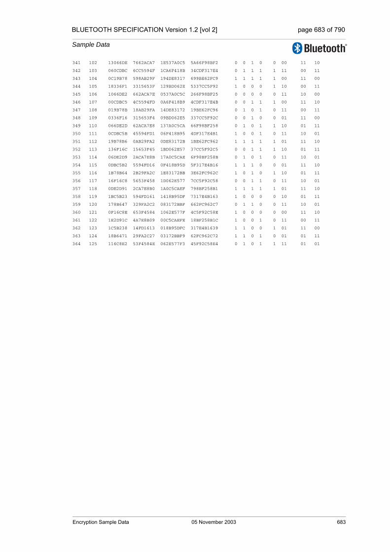
BLUETOOTH SPECIFICATION Version 1.2 [vol 2] page 683 of 790
Sample Data
341 102 13066DE 7662ACA7 1E537A0C5 5A66F98BF2 0 0 1 0 0 00 11 10
342 103 060CDBC 6CC5594F 1CA6F418B 34CDF317E4 0 1 1 1 1 11 00 11
343 104 0C19B78 598AB29F 194DE8317 699BE62FC9 1 1 1 1 1 00 11 00
344 105 18336F1 3315653F 129BD062E 5337CC5F92 1 0 0 0 1 10 00 11
345 106 1066DE2 662ACA7E 0537A0C5C 266F98BF25 0 0 0 0 0 11 10 00
346 107 00CDBC5 4C5594FD 0A6F418B9 4CDF317E4B 0 0 1 1 1 00 11 10
347 108 019B78B 18AB29FA 14DE83172 19BE62FC96 0 1 0 1 0 11 00 11
348 109 0336F16 315653F4 09BD062E5 337CC5F92C 0 0 1 0 0 01 11 00
349 110 066DE2D 62ACA7E8 137A0C5CA 66F98BF258 0 1 0 1 1 10 01 11
350 111 0CDBC5B 45594FD1 06F418B95 4DF317E4B1 1 0 0 1 0 11 10 01
351 112 19B78B6 0AB29FA2 0DE83172B 1BE62FC962 1 1 1 1 1 01 11 10
352 113 136F16C 15653F45 1BD062E57 37CC5F92C5 0 0 1 1 1 10 01 11
353 114 06DE2D9 2ACA7E8B 17A0C5CAE 6F98BF258B 0 1 0 1 0 11 10 01
354 115 0DBC5B2 5594FD16 0F418B95D 5F317E4B16 1 1 1 0 0 01 11 10
355 116 1B78B64 2B29FA2C 1E83172BB 3E62FC962C 1 0 1 0 1 10 01 11
356 117 16F16C8 5653F458 1D062E577 7CC5F92C58 0 0 1 1 0 11 10 01
357 118 0DE2D91 2CA7E8B0 1A0C5CAEF 798BF258B1 1 1 1 1 1 01 11 10
358 119 1BC5B23 594FD161 1418B95DF 7317E4B163 1 0 0 0 0 10 01 11
359 120 178B647 329FA2C2 083172BBF 662FC962C7 0 1 1 0 0 11 10 01
360 121 0F16C8E 653F4584 1062E577F 4C5F92C58E 1 0 0 0 0 00 11 10
361 122 1E2D91C 4A7E8B09 00C5CAEFE 18BF258B1C 1 0 0 1 0 11 00 11
362 123 1C5B238 14FD1613 018B95DFC 317E4B1639 1 1 0 0 1 01 11 00
363 124 18B6471 29FA2C27 03172BBF9 62FC962C72 1 1 0 1 0 01 01 11
364 125 116C8E2 53F4584E 062E577F3 45F92C58E4 0 1 0 1 1 11 01 01
Encryption Sample Data 05 November 2003 683

BLUETOOTH SPECIFICATION Version 1.2 [vol 2] page 684 of 790
Sample Data
684 05 November 2003 Encryption Sample Data
BLUETOOTH SPECIFICATION Version 1.2 [vol 2] page 685 of 790
Sample Data
2 FREQUENCY HOPPING SAMPLE DATA
The section contains three sets of sample data showing the basic and adapted hopping schemes for different combinations of addresses and initial clock val-ues.
Frequency Hopping Sample Data 05 November 2003 685
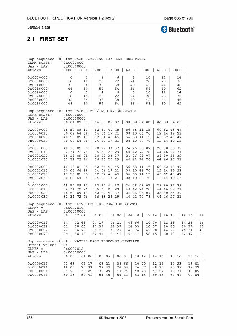
BLUETOOTH SPECIFICATION Version 1.2 [vol 2] page 686 of 790
Sample Data
1e ---- 16 32 48 00
e | ----1 | 2 | 9 | 4 |
2.1 FIRST SET
Hop sequence {k} for PAGE SCAN/INQUIRY SCAN SUBSTATE:CLKN start: 0x0000000UAP / LAP: 0x00000000#ticks: 0000 | 1000 | 2000 | 3000 | 4000 | 5000 | 6000 | 7000 |
--------------------------------------------------------0x0000000: 0 | 2 | 4 | 6 | 8 | 10 | 12 | 14 | 0x0008000: 16 | 18 | 20 | 22 | 24 | 26 | 28 | 30 | 0x0010000: 32 | 34 | 36 | 38 | 40 | 42 | 44 | 46 | 0x0018000: 48 | 50 | 52 | 54 | 56 | 58 | 60 | 62 | 0x0020000: 0 | 2 | 4 | 6 | 8 | 10 | 12 | 14 | 0x0028000: 16 | 18 | 20 | 22 | 24 | 26 | 28 | 30 | 0x0030000: 32 | 34 | 36 | 38 | 40 | 42 | 44 | 46 | 0x0038000: 48 | 50 | 52 | 54 | 56 | 58 | 60 | 62 |
Hop sequence {k} for PAGE STATE/INQUIRY SUBSTATE:CLKE start: 0x0000000UAP / LAP: 0x00000000#ticks: 00 01 02 03 | 04 05 06 07 | 08 09 0a 0b | 0c 0d 0e 0f |
--------------------------------------------------------0x0000000: 48 50 09 13 | 52 54 41 45 | 56 58 11 15 | 60 62 43 47 | 0x0000010: 00 02 64 68 | 04 06 17 21 | 08 10 66 70 | 12 14 19 23 | 0x0000020: 48 50 09 13 | 52 54 41 45 | 56 58 11 15 | 60 62 43 47 | 0x0000030: 00 02 64 68 | 04 06 17 21 | 08 10 66 70 | 12 14 19 23 | ...0x0001000: 48 18 09 05 | 20 22 33 37 | 24 26 03 07 | 28 30 35 39 | 0x0001010: 32 34 72 76 | 36 38 25 29 | 40 42 74 78 | 44 46 27 31 | 0x0001020: 48 18 09 05 | 20 22 33 37 | 24 26 03 07 | 28 30 35 39 | 0x0001030: 32 34 72 76 | 36 38 25 29 | 40 42 74 78 | 44 46 27 31 | ...0x0002000: 16 18 01 05 | 52 54 41 45 | 56 58 11 15 | 60 62 43 47 | 0x0002010: 00 02 64 68 | 04 06 17 21 | 08 10 66 70 | 12 14 19 23 | 0x0002020: 16 18 01 05 | 52 54 41 45 | 56 58 11 15 | 60 62 43 47 | 0x0002030: 00 02 64 68 | 04 06 17 21 | 08 10 66 70 | 12 14 19 23 | ...0x0003000: 48 50 09 13 | 52 22 41 37 | 24 26 03 07 | 28 30 35 39 | 0x0003010: 32 34 72 76 | 36 38 25 29 | 40 42 74 78 | 44 46 27 31 | 0x0003020: 48 50 09 13 | 52 22 41 37 | 24 26 03 07 | 28 30 35 39 | 0x0003030: 32 34 72 76 | 36 38 25 29 | 40 42 74 78 | 44 46 27 31 |
Hop sequence {k} for SLAVE PAGE RESPONSE SUBSTATE:CLKN* = 0x0000010UAP / LAP: 0x00000000#ticks: 00 | 02 04 | 06 08 | 0a 0c | 0e 10 | 12 14 | 16 18 | 1a 1c |
------------------------------------------------------------0x0000012: 64 | 02 68 | 04 17 | 06 21 | 08 66 | 10 70 | 12 19 | 14 23 |0x0000032: 01 | 18 05 | 20 33 | 22 37 | 24 03 | 26 07 | 28 35 | 30 39 |0x0000052: 72 | 34 76 | 36 25 | 38 29 | 40 74 | 42 78 | 44 27 | 46 31 |0x0000072: 09 | 50 13 | 52 41 | 54 45 | 56 11 | 58 15 | 60 43 | 62 47 |
Hop sequence {k} for MASTER PAGE RESPONSE SUBSTATE:Offset value: 24CLKE* = 0x0000012UAP / LAP: 0x00000000#ticks: 00 02 | 04 06 | 08 0a | 0c 0e | 10 12 | 14 16 | 18 1a | 1c 1
------------------------------------------------------------0x0000014: 02 68 | 04 17 | 06 21 | 08 66 | 10 70 | 12 19 | 14 23 | 16 00x0000034: 18 05 | 20 33 | 22 37 | 24 03 | 26 07 | 28 35 | 30 39 | 32 70x0000054: 34 76 | 36 25 | 38 29 | 40 74 | 42 78 | 44 27 | 46 31 | 48 00x0000074: 50 13 | 52 41 | 54 45 | 56 11 | 58 15 | 60 43 | 62 47 | 00 6
P 1
686 05 November 2003 Frequency Hopping Sample Data
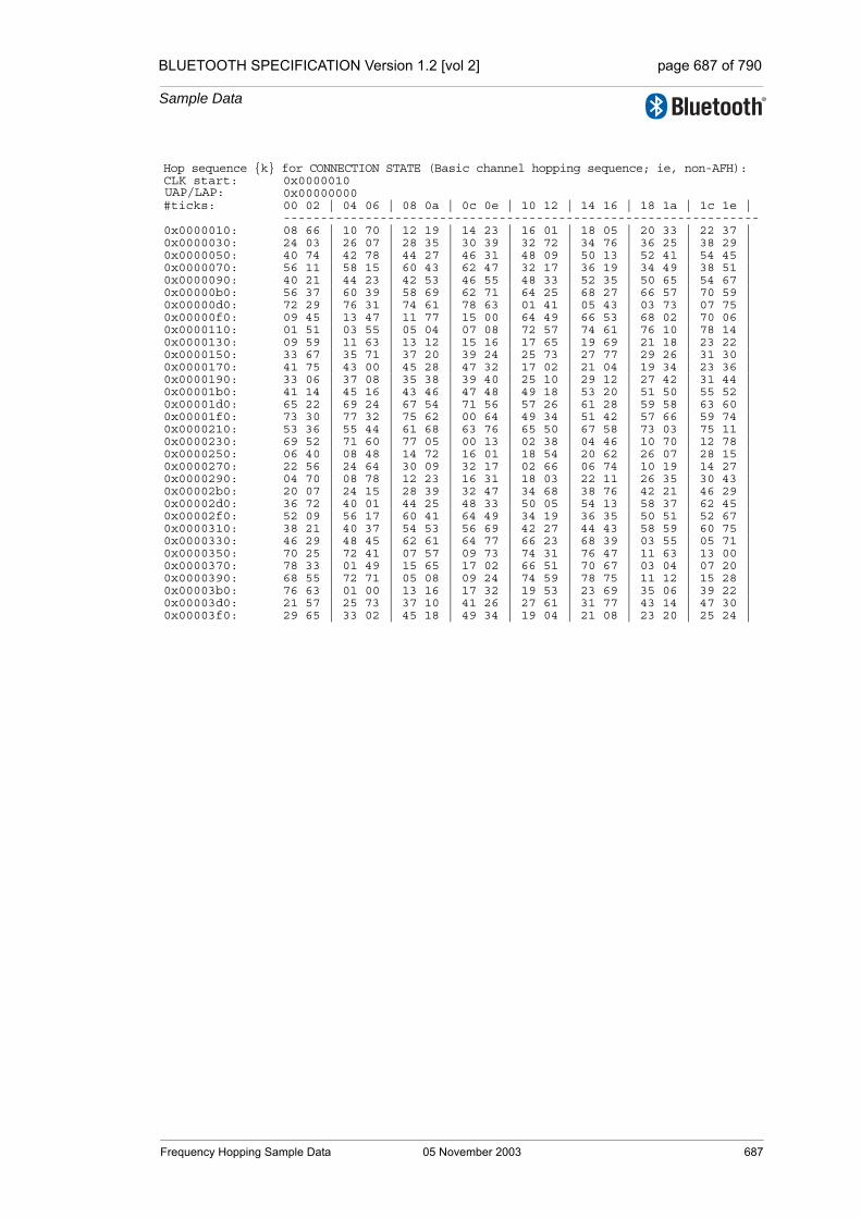
BLUETOOTH SPECIFICATION Version 1.2 [vol 2] page 687 of 790
Sample Data
Hop sequence {k} for CONNECTION STATE (Basic channel hopping sequence; ie, non-AFH):CLK start: 0x0000010
0x00000000#ticks: 00 02 | 04 06 | 08 0a | 0c 0e | 10 12 | 14 16 | 18 1a | 1c 1e |
----------------------------------------------------------------0x0000010: 08 66 | 10 70 | 12 19 | 14 23 | 16 01 | 18 05 | 20 33 | 22 37 | 0x0000030: 24 03 | 26 07 | 28 35 | 30 39 | 32 72 | 34 76 | 36 25 | 38 29 | 0x0000050: 40 74 | 42 78 | 44 27 | 46 31 | 48 09 | 50 13 | 52 41 | 54 45 | 0x0000070: 56 11 | 58 15 | 60 43 | 62 47 | 32 17 | 36 19 | 34 49 | 38 51 | 0x0000090: 40 21 | 44 23 | 42 53 | 46 55 | 48 33 | 52 35 | 50 65 | 54 67 | 0x00000b0: 56 37 | 60 39 | 58 69 | 62 71 | 64 25 | 68 27 | 66 57 | 70 59 | 0x00000d0: 72 29 | 76 31 | 74 61 | 78 63 | 01 41 | 05 43 | 03 73 | 07 75 | 0x00000f0: 09 45 | 13 47 | 11 77 | 15 00 | 64 49 | 66 53 | 68 02 | 70 06 | 0x0000110: 01 51 | 03 55 | 05 04 | 07 08 | 72 57 | 74 61 | 76 10 | 78 14 | 0x0000130: 09 59 | 11 63 | 13 12 | 15 16 | 17 65 | 19 69 | 21 18 | 23 22 | 0x0000150: 33 67 | 35 71 | 37 20 | 39 24 | 25 73 | 27 77 | 29 26 | 31 30 | 0x0000170: 41 75 | 43 00 | 45 28 | 47 32 | 17 02 | 21 04 | 19 34 | 23 36 | 0x0000190: 33 06 | 37 08 | 35 38 | 39 40 | 25 10 | 29 12 | 27 42 | 31 44 | 0x00001b0: 41 14 | 45 16 | 43 46 | 47 48 | 49 18 | 53 20 | 51 50 | 55 52 | 0x00001d0: 65 22 | 69 24 | 67 54 | 71 56 | 57 26 | 61 28 | 59 58 | 63 60 | 0x00001f0: 73 30 | 77 32 | 75 62 | 00 64 | 49 34 | 51 42 | 57 66 | 59 74 | 0x0000210: 53 36 | 55 44 | 61 68 | 63 76 | 65 50 | 67 58 | 73 03 | 75 11 | 0x0000230: 69 52 | 71 60 | 77 05 | 00 13 | 02 38 | 04 46 | 10 70 | 12 78 | 0x0000250: 06 40 | 08 48 | 14 72 | 16 01 | 18 54 | 20 62 | 26 07 | 28 15 | 0x0000270: 22 56 | 24 64 | 30 09 | 32 17 | 02 66 | 06 74 | 10 19 | 14 27 | 0x0000290: 04 70 | 08 78 | 12 23 | 16 31 | 18 03 | 22 11 | 26 35 | 30 43 | 0x00002b0: 20 07 | 24 15 | 28 39 | 32 47 | 34 68 | 38 76 | 42 21 | 46 29 | 0x00002d0: 36 72 | 40 01 | 44 25 | 48 33 | 50 05 | 54 13 | 58 37 | 62 45 | 0x00002f0: 52 09 | 56 17 | 60 41 | 64 49 | 34 19 | 36 35 | 50 51 | 52 67 | 0x0000310: 38 21 | 40 37 | 54 53 | 56 69 | 42 27 | 44 43 | 58 59 | 60 75 | 0x0000330: 46 29 | 48 45 | 62 61 | 64 77 | 66 23 | 68 39 | 03 55 | 05 71 | 0x0000350: 70 25 | 72 41 | 07 57 | 09 73 | 74 31 | 76 47 | 11 63 | 13 00 | 0x0000370: 78 33 | 01 49 | 15 65 | 17 02 | 66 51 | 70 67 | 03 04 | 07 20 | 0x0000390: 68 55 | 72 71 | 05 08 | 09 24 | 74 59 | 78 75 | 11 12 | 15 28 | 0x00003b0: 76 63 | 01 00 | 13 16 | 17 32 | 19 53 | 23 69 | 35 06 | 39 22 | 0x00003d0: 21 57 | 25 73 | 37 10 | 41 26 | 27 61 | 31 77 | 43 14 | 47 30 | 0x00003f0: 29 65 | 33 02 | 45 18 | 49 34 | 19 04 | 21 08 | 23 20 | 25 24 |
UAP/LAP:
Frequency Hopping Sample Data 05 November 2003 687
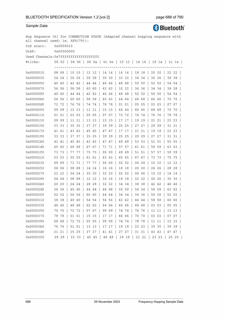
BLUETOOTH SPECIFICATION Version 1.2 [vol 2] page 688 of 790
Sample Data
Hop Sequence {k} for CONNECTION STATE (Adapted channel hopping sequence with all channel used; ie, AFH(79)):
CLK start: 0x0000010
ULAP: 0x00000000
Used Channels:0x7fffffffffffffffffff
#ticks: 00 02 | 04 06 | 08 0a | 0c 0e | 10 12 | 14 16 | 18 1a | 1c 1e |
---------------------------------------------------------------
0x0000010 08 08 | 10 10 | 12 12 | 14 14 | 16 16 | 18 18 | 20 20 | 22 22 |
0x0000030 24 24 | 26 26 | 28 28 | 30 30 | 32 32 | 34 34 | 36 36 | 38 38 |
0x0000050 40 40 | 42 42 | 44 44 | 46 46 | 48 48 | 50 50 | 52 52 | 54 54 |
0x0000070 56 56 | 58 58 | 60 60 | 62 62 | 32 32 | 36 36 | 34 34 | 38 38 |
0x0000090 40 40 | 44 44 | 42 42 | 46 46 | 48 48 | 52 52 | 50 50 | 54 54 |
0x00000b0 56 56 | 60 60 | 58 58 | 62 62 | 64 64 | 68 68 | 66 66 | 70 70 |
0x00000d0 72 72 | 76 76 | 74 74 | 78 78 | 01 01 | 05 05 | 03 03 | 07 07 |
0x00000f0 09 09 | 13 13 | 11 11 | 15 15 | 64 64 | 66 66 | 68 68 | 70 70 |
0x0000110 01 01 | 03 03 | 05 05 | 07 07 | 72 72 | 74 74 | 76 76 | 78 78 |
0x0000130 09 09 | 11 11 | 13 13 | 15 15 | 17 17 | 19 19 | 21 21 | 23 23 |
0x0000150 33 33 | 35 35 | 37 37 | 39 39 | 25 25 | 27 27 | 29 29 | 31 31 |
0x0000170 41 41 | 43 43 | 45 45 | 47 47 | 17 17 | 21 21 | 19 19 | 23 23 |
0x0000190 33 33 | 37 37 | 35 35 | 39 39 | 25 25 | 29 29 | 27 27 | 31 31 |
0x00001b0 41 41 | 45 45 | 43 43 | 47 47 | 49 49 | 53 53 | 51 51 | 55 55 |
0x00001d0 65 65 | 69 69 | 67 67 | 71 71 | 57 57 | 61 61 | 59 59 | 63 63 |
0x00001f0 73 73 | 77 77 | 75 75 | 00 00 | 49 49 | 51 51 | 57 57 | 59 59 |
0x0000210 53 53 | 55 55 | 61 61 | 63 63 | 65 65 | 67 67 | 73 73 | 75 75 |
0x0000230 69 69 | 71 71 | 77 77 | 00 00 | 02 02 | 04 04 | 10 10 | 12 12 |
0x0000250 06 06 | 08 08 | 14 14 | 16 16 | 18 18 | 20 20 | 26 26 | 28 28 |
0x0000270 22 22 | 24 24 | 30 30 | 32 32 | 02 02 | 06 06 | 10 10 | 14 14 |
0x0000290 04 04 | 08 08 | 12 12 | 16 16 | 18 18 | 22 22 | 26 26 | 30 30 |
0x00002b0 20 20 | 24 24 | 28 28 | 32 32 | 34 34 | 38 38 | 42 42 | 46 46 |
0x00002d0 36 36 | 40 40 | 44 44 | 48 48 | 50 50 | 54 54 | 58 58 | 62 62 |
0x00002f0 52 52 | 56 56 | 60 60 | 64 64 | 34 34 | 36 36 | 50 50 | 52 52 |
0x0000310 38 38 | 40 40 | 54 54 | 56 56 | 42 42 | 44 44 | 58 58 | 60 60 |
0x0000330 46 46 | 48 48 | 62 62 | 64 64 | 66 66 | 68 68 | 03 03 | 05 05 |
0x0000350 70 70 | 72 72 | 07 07 | 09 09 | 74 74 | 76 76 | 11 11 | 13 13 |
0x0000370 78 78 | 01 01 | 15 15 | 17 17 | 66 66 | 70 70 | 03 03 | 07 07 |
0x0000390 68 68 | 72 72 | 05 05 | 09 09 | 74 74 | 78 78 | 11 11 | 15 15 |
0x00003b0 76 76 | 01 01 | 13 13 | 17 17 | 19 19 | 23 23 | 35 35 | 39 39 |
0x00003d0 21 21 | 25 25 | 37 37 | 41 41 | 27 27 | 31 31 | 43 43 | 47 47 |
0x00003f0 29 29 | 33 33 | 45 45 | 49 49 | 19 19 | 21 21 | 23 23 | 25 25 |
688 05 November 2003 Frequency Hopping Sample Data

BLUETOOTH SPECIFICATION Version 1.2 [vol 2] page 689 of 790
Sample Data
Hop Sequence {k} for CONNECTION STATE (Adapted channel hopping sequence with channels 0 to 21 unused):
CLK start: 0x0000010
ULAP: 0x00000000
Used Channels:0x7fffffffffffffc00000
#ticks: 00 02 | 04 06 | 08 0a | 0c 0e | 10 12 | 14 16 | 18 1a | 1c 1e |
---------------------------------------------------------------
0x0000010 30 30 | 32 32 | 34 34 | 36 36 | 38 38 | 40 40 | 42 42 | 22 22 |
0x0000030 24 24 | 26 26 | 28 28 | 30 30 | 32 32 | 34 34 | 36 36 | 38 38 |
0x0000050 40 40 | 42 42 | 44 44 | 46 46 | 48 48 | 50 50 | 52 52 | 54 54 |
0x0000070 56 56 | 58 58 | 60 60 | 62 62 | 32 32 | 36 36 | 34 34 | 38 38 |
0x0000090 40 40 | 44 44 | 42 42 | 46 46 | 48 48 | 52 52 | 50 50 | 54 54 |
0x00000b0 56 56 | 60 60 | 58 58 | 62 62 | 64 64 | 68 68 | 66 66 | 70 70 |
0x00000d0 72 72 | 76 76 | 74 74 | 78 78 | 45 45 | 49 49 | 47 47 | 51 51 |
0x00000f0 53 53 | 57 57 | 55 55 | 59 59 | 64 64 | 66 66 | 68 68 | 70 70 |
0x0000110 45 45 | 47 47 | 49 49 | 51 51 | 72 72 | 74 74 | 76 76 | 78 78 |
0x0000130 53 53 | 55 55 | 57 57 | 59 59 | 61 61 | 63 63 | 65 65 | 23 23 |
0x0000150 33 33 | 35 35 | 37 37 | 39 39 | 25 25 | 27 27 | 29 29 | 31 31 |
0x0000170 41 41 | 43 43 | 45 45 | 47 47 | 61 61 | 65 65 | 63 63 | 23 23 |
0x0000190 33 33 | 37 37 | 35 35 | 39 39 | 25 25 | 29 29 | 27 27 | 31 31 |
0x00001b0 41 41 | 45 45 | 43 43 | 47 47 | 49 49 | 53 53 | 51 51 | 55 55 |
0x00001d0 65 65 | 69 69 | 67 67 | 71 71 | 57 57 | 61 61 | 59 59 | 63 63 |
0x00001f0 73 73 | 77 77 | 75 75 | 66 66 | 49 49 | 51 51 | 57 57 | 59 59 |
0x0000210 53 53 | 55 55 | 61 61 | 63 63 | 65 65 | 67 67 | 73 73 | 75 75 |
0x0000230 69 69 | 71 71 | 77 77 | 66 66 | 68 68 | 70 70 | 76 76 | 78 78 |
0x0000250 72 72 | 74 74 | 23 23 | 25 25 | 27 27 | 29 29 | 26 26 | 28 28 |
0x0000270 22 22 | 24 24 | 30 30 | 32 32 | 68 68 | 72 72 | 76 76 | 23 23 |
0x0000290 70 70 | 74 74 | 78 78 | 25 25 | 27 27 | 22 22 | 26 26 | 30 30 |
0x00002b0 29 29 | 24 24 | 28 28 | 32 32 | 34 34 | 38 38 | 42 42 | 46 46 |
0x00002d0 36 36 | 40 40 | 44 44 | 48 48 | 50 50 | 54 54 | 58 58 | 62 62 |
0x00002f0 52 52 | 56 56 | 60 60 | 64 64 | 34 34 | 36 36 | 50 50 | 52 52 |
0x0000310 38 38 | 40 40 | 54 54 | 56 56 | 42 42 | 44 44 | 58 58 | 60 60 |
0x0000330 46 46 | 48 48 | 62 62 | 64 64 | 66 66 | 68 68 | 34 34 | 36 36 |
0x0000350 70 70 | 72 72 | 38 38 | 40 40 | 74 74 | 76 76 | 42 42 | 44 44 |
0x0000370 78 78 | 32 32 | 46 46 | 48 48 | 66 66 | 70 70 | 34 34 | 38 38 |
0x0000390 68 68 | 72 72 | 36 36 | 40 40 | 74 74 | 78 78 | 42 42 | 46 46 |
0x00003b0 76 76 | 32 32 | 44 44 | 48 48 | 50 50 | 23 23 | 35 35 | 39 39 |
0x00003d0 52 52 | 25 25 | 37 37 | 41 41 | 27 27 | 31 31 | 43 43 | 47 47 |
0x00003f0 29 29 | 33 33 | 45 45 | 49 49 | 50 50 | 52 52 | 23 23 | 25 25 |
Frequency Hopping Sample Data 05 November 2003 689

BLUETOOTH SPECIFICATION Version 1.2 [vol 2] page 690 of 790
Sample Data
Hop Sequence {k} for CONNECTION STATE (Adapted channel hopping sequence with even channels used):
CLK start: 0x0000010
ULAP: 0x00000000
Used Channels:0x55555555555555555555
#ticks: 00 02 | 04 06 | 08 0a | 0c 0e | 10 12 | 14 16 | 18 1a | 1c 1e |
---------------------------------------------------------------
0x0000010 08 08 | 10 10 | 12 12 | 14 14 | 16 16 | 18 18 | 20 20 | 22 22 |
0x0000030 24 24 | 26 26 | 28 28 | 30 30 | 32 32 | 34 34 | 36 36 | 38 38 |
0x0000050 40 40 | 42 42 | 44 44 | 46 46 | 48 48 | 50 50 | 52 52 | 54 54 |
0x0000070 56 56 | 58 58 | 60 60 | 62 62 | 32 32 | 36 36 | 34 34 | 38 38 |
0x0000090 40 40 | 44 44 | 42 42 | 46 46 | 48 48 | 52 52 | 50 50 | 54 54 |
0x00000b0 56 56 | 60 60 | 58 58 | 62 62 | 64 64 | 68 68 | 66 66 | 70 70 |
0x00000d0 72 72 | 76 76 | 74 74 | 78 78 | 00 00 | 04 04 | 02 02 | 06 06 |
0x00000f0 08 08 | 12 12 | 10 10 | 14 14 | 64 64 | 66 66 | 68 68 | 70 70 |
0x0000110 00 00 | 02 02 | 04 04 | 06 06 | 72 72 | 74 74 | 76 76 | 78 78 |
0x0000130 08 08 | 10 10 | 12 12 | 14 14 | 16 16 | 18 18 | 20 20 | 22 22 |
0x0000150 32 32 | 34 34 | 36 36 | 38 38 | 24 24 | 26 26 | 28 28 | 30 30 |
0x0000170 40 40 | 42 42 | 44 44 | 46 46 | 16 16 | 20 20 | 18 18 | 22 22 |
0x0000190 32 32 | 36 36 | 34 34 | 38 38 | 24 24 | 28 28 | 26 26 | 30 30 |
0x00001b0 40 40 | 44 44 | 42 42 | 46 46 | 48 48 | 52 52 | 50 50 | 54 54 |
0x00001d0 64 64 | 68 68 | 66 66 | 70 70 | 56 56 | 60 60 | 58 58 | 62 62 |
0x00001f0 72 72 | 76 76 | 74 74 | 00 00 | 48 48 | 50 50 | 56 56 | 58 58 |
0x0000210 52 52 | 54 54 | 60 60 | 62 62 | 64 64 | 66 66 | 72 72 | 74 74 |
0x0000230 68 68 | 70 70 | 76 76 | 00 00 | 02 02 | 04 04 | 10 10 | 12 12 |
0x0000250 06 06 | 08 08 | 14 14 | 16 16 | 18 18 | 20 20 | 26 26 | 28 28 |
0x0000270 22 22 | 24 24 | 30 30 | 32 32 | 02 02 | 06 06 | 10 10 | 14 14 |
0x0000290 04 04 | 08 08 | 12 12 | 16 16 | 18 18 | 22 22 | 26 26 | 30 30 |
0x00002b0 20 20 | 24 24 | 28 28 | 32 32 | 34 34 | 38 38 | 42 42 | 46 46 |
0x00002d0 36 36 | 40 40 | 44 44 | 48 48 | 50 50 | 54 54 | 58 58 | 62 62 |
0x00002f0 52 52 | 56 56 | 60 60 | 64 64 | 34 34 | 36 36 | 50 50 | 52 52 |
0x0000310 38 38 | 40 40 | 54 54 | 56 56 | 42 42 | 44 44 | 58 58 | 60 60 |
0x0000330 46 46 | 48 48 | 62 62 | 64 64 | 66 66 | 68 68 | 00 00 | 02 02 |
0x0000350 70 70 | 72 72 | 04 04 | 06 06 | 74 74 | 76 76 | 08 08 | 10 10 |
0x0000370 78 78 | 78 78 | 12 12 | 14 14 | 66 66 | 70 70 | 00 00 | 04 04 |
0x0000390 68 68 | 72 72 | 02 02 | 06 06 | 74 74 | 78 78 | 08 08 | 12 12 |
0x00003b0 76 76 | 78 78 | 10 10 | 14 14 | 16 16 | 20 20 | 32 32 | 36 36 |
0x00003d0 18 18 | 22 22 | 34 34 | 38 38 | 24 24 | 28 28 | 40 40 | 44 44 |
0x00003f0 26 26 | 30 30 | 42 42 | 46 46 | 16 16 | 18 18 | 20 20 | 22 22 |
690 05 November 2003 Frequency Hopping Sample Data

BLUETOOTH SPECIFICATION Version 1.2 [vol 2] page 691 of 790
Sample Data
Hop Sequence {k} for CONNECTION STATE (Adapted channel hopping sequence with odd channels used):
CLK start: 0x0000010
ULAP: 0x00000000
Used Channels:0x2aaaaaaaaaaaaaaaaaaa
#ticks: 00 02 | 04 06 | 08 0a | 0c 0e | 10 12 | 14 16 | 18 1a | 1c 1e |
---------------------------------------------------------------
0x0000010 09 09 | 11 11 | 13 13 | 15 15 | 17 17 | 19 19 | 21 21 | 23 23 |
0x0000030 25 25 | 27 27 | 29 29 | 31 31 | 33 33 | 35 35 | 37 37 | 39 39 |
0x0000050 41 41 | 43 43 | 45 45 | 47 47 | 49 49 | 51 51 | 53 53 | 55 55 |
0x0000070 57 57 | 59 59 | 61 61 | 63 63 | 33 33 | 37 37 | 35 35 | 39 39 |
0x0000090 41 41 | 45 45 | 43 43 | 47 47 | 49 49 | 53 53 | 51 51 | 55 55 |
0x00000b0 57 57 | 61 61 | 59 59 | 63 63 | 65 65 | 69 69 | 67 67 | 71 71 |
0x00000d0 73 73 | 77 77 | 75 75 | 01 01 | 01 01 | 05 05 | 03 03 | 07 07 |
0x00000f0 09 09 | 13 13 | 11 11 | 15 15 | 65 65 | 67 67 | 69 69 | 71 71 |
0x0000110 01 01 | 03 03 | 05 05 | 07 07 | 73 73 | 75 75 | 77 77 | 01 01 |
0x0000130 09 09 | 11 11 | 13 13 | 15 15 | 17 17 | 19 19 | 21 21 | 23 23 |
0x0000150 33 33 | 35 35 | 37 37 | 39 39 | 25 25 | 27 27 | 29 29 | 31 31 |
0x0000170 41 41 | 43 43 | 45 45 | 47 47 | 17 17 | 21 21 | 19 19 | 23 23 |
0x0000190 33 33 | 37 37 | 35 35 | 39 39 | 25 25 | 29 29 | 27 27 | 31 31 |
0x00001b0 41 41 | 45 45 | 43 43 | 47 47 | 49 49 | 53 53 | 51 51 | 55 55 |
0x00001d0 65 65 | 69 69 | 67 67 | 71 71 | 57 57 | 61 61 | 59 59 | 63 63 |
0x00001f0 73 73 | 77 77 | 75 75 | 03 03 | 49 49 | 51 51 | 57 57 | 59 59 |
0x0000210 53 53 | 55 55 | 61 61 | 63 63 | 65 65 | 67 67 | 73 73 | 75 75 |
0x0000230 69 69 | 71 71 | 77 77 | 03 03 | 05 05 | 07 07 | 13 13 | 15 15 |
0x0000250 09 09 | 11 11 | 17 17 | 19 19 | 21 21 | 23 23 | 29 29 | 31 31 |
0x0000270 25 25 | 27 27 | 33 33 | 35 35 | 05 05 | 09 09 | 13 13 | 17 17 |
0x0000290 07 07 | 11 11 | 15 15 | 19 19 | 21 21 | 25 25 | 29 29 | 33 33 |
0x00002b0 23 23 | 27 27 | 31 31 | 35 35 | 37 37 | 41 41 | 45 45 | 49 49 |
0x00002d0 39 39 | 43 43 | 47 47 | 51 51 | 53 53 | 57 57 | 61 61 | 65 65 |
0x00002f0 55 55 | 59 59 | 63 63 | 67 67 | 37 37 | 39 39 | 53 53 | 55 55 |
0x0000310 41 41 | 43 43 | 57 57 | 59 59 | 45 45 | 47 47 | 61 61 | 63 63 |
0x0000330 49 49 | 51 51 | 65 65 | 67 67 | 69 69 | 71 71 | 03 03 | 05 05 |
0x0000350 73 73 | 75 75 | 07 07 | 09 09 | 77 77 | 01 01 | 11 11 | 13 13 |
0x0000370 03 03 | 01 01 | 15 15 | 17 17 | 69 69 | 73 73 | 03 03 | 07 07 |
0x0000390 71 71 | 75 75 | 05 05 | 09 09 | 77 77 | 03 03 | 11 11 | 15 15 |
0x00003b0 01 01 | 01 01 | 13 13 | 17 17 | 19 19 | 23 23 | 35 35 | 39 39 |
0x00003d0 21 21 | 25 25 | 37 37 | 41 41 | 27 27 | 31 31 | 43 43 | 47 47 |
0x00003f0 29 29 | 33 33 | 45 45 | 49 49 | 19 19 | 21 21 | 23 23 | 25 25 |
Frequency Hopping Sample Data 05 November 2003 691
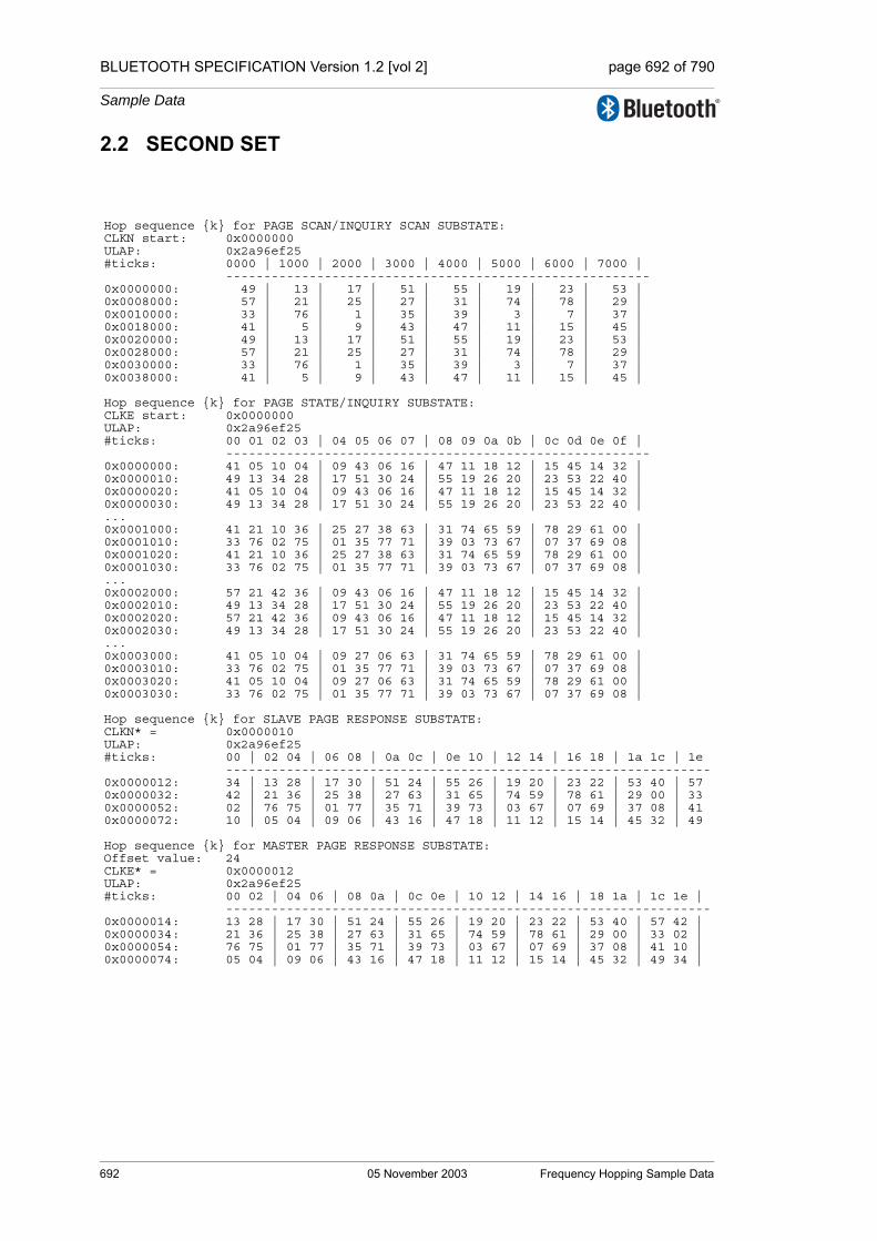
BLUETOOTH SPECIFICATION Version 1.2 [vol 2] page 692 of 790
Sample Data
2.2 SECOND SET
Hop sequence {k} for PAGE SCAN/INQUIRY SCAN SUBSTATE:CLKN start: 0x0000000ULAP: 0x2a96ef25#ticks: 0000 | 1000 | 2000 | 3000 | 4000 | 5000 | 6000 | 7000 |
--------------------------------------------------------0x0000000: 49 | 13 | 17 | 51 | 55 | 19 | 23 | 53 | 0x0008000: 57 | 21 | 25 | 27 | 31 | 74 | 78 | 29 | 0x0010000: 33 | 76 | 1 | 35 | 39 | 3 | 7 | 37 | 0x0018000: 41 | 5 | 9 | 43 | 47 | 11 | 15 | 45 | 0x0020000: 49 | 13 | 17 | 51 | 55 | 19 | 23 | 53 | 0x0028000: 57 | 21 | 25 | 27 | 31 | 74 | 78 | 29 | 0x0030000: 33 | 76 | 1 | 35 | 39 | 3 | 7 | 37 | 0x0038000: 41 | 5 | 9 | 43 | 47 | 11 | 15 | 45 |
Hop sequence {k} for PAGE STATE/INQUIRY SUBSTATE:CLKE start: 0x0000000ULAP: 0x2a96ef25#ticks: 00 01 02 03 | 04 05 06 07 | 08 09 0a 0b | 0c 0d 0e 0f |
--------------------------------------------------------0x0000000: 41 05 10 04 | 09 43 06 16 | 47 11 18 12 | 15 45 14 32 | 0x0000010: 49 13 34 28 | 17 51 30 24 | 55 19 26 20 | 23 53 22 40 | 0x0000020: 41 05 10 04 | 09 43 06 16 | 47 11 18 12 | 15 45 14 32 | 0x0000030: 49 13 34 28 | 17 51 30 24 | 55 19 26 20 | 23 53 22 40 | ...0x0001000: 41 21 10 36 | 25 27 38 63 | 31 74 65 59 | 78 29 61 00 | 0x0001010: 33 76 02 75 | 01 35 77 71 | 39 03 73 67 | 07 37 69 08 | 0x0001020: 41 21 10 36 | 25 27 38 63 | 31 74 65 59 | 78 29 61 00 | 0x0001030: 33 76 02 75 | 01 35 77 71 | 39 03 73 67 | 07 37 69 08 | ...0x0002000: 57 21 42 36 | 09 43 06 16 | 47 11 18 12 | 15 45 14 32 | 0x0002010: 49 13 34 28 | 17 51 30 24 | 55 19 26 20 | 23 53 22 40 | 0x0002020: 57 21 42 36 | 09 43 06 16 | 47 11 18 12 | 15 45 14 32 | 0x0002030: 49 13 34 28 | 17 51 30 24 | 55 19 26 20 | 23 53 22 40 | ...0x0003000: 41 05 10 04 | 09 27 06 63 | 31 74 65 59 | 78 29 61 00 | 0x0003010: 33 76 02 75 | 01 35 77 71 | 39 03 73 67 | 07 37 69 08 | 0x0003020: 41 05 10 04 | 09 27 06 63 | 31 74 65 59 | 78 29 61 00 | 0x0003030: 33 76 02 75 | 01 35 77 71 | 39 03 73 67 | 07 37 69 08 |
Hop sequence {k} for SLAVE PAGE RESPONSE SUBSTATE:CLKN* = 0x0000010ULAP: 0x2a96ef25#ticks: 00 | 02 04 | 06 08 | 0a 0c | 0e 10 | 12 14 | 16 18 | 1a 1c | 1e
----------------------------------------------------------------0x0000012: 34 | 13 28 | 17 30 | 51 24 | 55 26 | 19 20 | 23 22 | 53 40 | 57 0x0000032: 42 | 21 36 | 25 38 | 27 63 | 31 65 | 74 59 | 78 61 | 29 00 | 33 0x0000052: 02 | 76 75 | 01 77 | 35 71 | 39 73 | 03 67 | 07 69 | 37 08 | 41 0x0000072: 10 | 05 04 | 09 06 | 43 16 | 47 18 | 11 12 | 15 14 | 45 32 | 49
Hop sequence {k} for MASTER PAGE RESPONSE SUBSTATE:Offset value: 24CLKE* = 0x0000012ULAP: 0x2a96ef25#ticks: 00 02 | 04 06 | 08 0a | 0c 0e | 10 12 | 14 16 | 18 1a | 1c 1e |
----------------------------------------------------------------0x0000014: 13 28 | 17 30 | 51 24 | 55 26 | 19 20 | 23 22 | 53 40 | 57 42 | 0x0000034: 21 36 | 25 38 | 27 63 | 31 65 | 74 59 | 78 61 | 29 00 | 33 02 | 0x0000054: 76 75 | 01 77 | 35 71 | 39 73 | 03 67 | 07 69 | 37 08 | 41 10 | 0x0000074: 05 04 | 09 06 | 43 16 | 47 18 | 11 12 | 15 14 | 45 32 | 49 34 |
692 05 November 2003 Frequency Hopping Sample Data

BLUETOOTH SPECIFICATION Version 1.2 [vol 2] page 693 of 790
Sample Data
Hop sequence {k} for CONNECTION STATE (Basic channel hopping sequence; ie, non-AFH):CLK start: 0x0000010ULAP: 0x2a96ef25#ticks: 00 02 | 04 06 | 08 0a | 0c 0e | 10 12 | 14 16 | 18 1a | 1c 1e |
----------------------------------------------------------------0x0000010: 55 26 | 19 20 | 23 22 | 53 40 | 57 42 | 21 36 | 25 38 | 27 63 | 0x0000030: 31 65 | 74 59 | 78 61 | 29 00 | 33 02 | 76 75 | 01 77 | 35 71 | 0x0000050: 39 73 | 03 67 | 07 69 | 37 08 | 41 10 | 05 04 | 09 06 | 43 16 | 0x0000070: 47 18 | 11 12 | 15 14 | 45 32 | 02 66 | 47 60 | 49 64 | 04 54 | 0x0000090: 06 58 | 51 52 | 53 56 | 08 70 | 10 74 | 55 68 | 57 72 | 59 14 | 0x00000b0: 61 18 | 27 12 | 29 16 | 63 30 | 65 34 | 31 28 | 33 32 | 67 22 | 0x00000d0: 69 26 | 35 20 | 37 24 | 71 38 | 73 42 | 39 36 | 41 40 | 75 46 | 0x00000f0: 77 50 | 43 44 | 45 48 | 00 62 | 26 11 | 69 05 | 73 07 | 36 17 | 0x0000110: 40 19 | 04 13 | 08 15 | 38 25 | 42 27 | 06 21 | 10 23 | 12 48 | 0x0000130: 16 50 | 59 44 | 63 46 | 14 56 | 18 58 | 61 52 | 65 54 | 28 64 | 0x0000150: 32 66 | 75 60 | 00 62 | 30 72 | 34 74 | 77 68 | 02 70 | 20 01 | 0x0000170: 24 03 | 67 76 | 71 78 | 22 09 | 58 43 | 24 37 | 26 41 | 68 47 | 0x0000190: 70 51 | 36 45 | 38 49 | 72 55 | 74 59 | 40 53 | 42 57 | 44 78 | 0x00001b0: 46 03 | 12 76 | 14 01 | 48 07 | 50 11 | 16 05 | 18 09 | 60 15 | 0x00001d0: 62 19 | 28 13 | 30 17 | 64 23 | 66 27 | 32 21 | 34 25 | 52 31 | 0x00001f0: 54 35 | 20 29 | 22 33 | 56 39 | 19 04 | 62 63 | 66 00 | 07 73 | 0x0000210: 11 10 | 54 69 | 58 06 | 23 75 | 27 12 | 70 71 | 74 08 | 76 33 | 0x0000230: 01 49 | 44 29 | 48 45 | 13 35 | 17 51 | 60 31 | 64 47 | 05 41 | 0x0000250: 09 57 | 52 37 | 56 53 | 21 43 | 25 59 | 68 39 | 72 55 | 78 65 | 0x0000270: 03 02 | 46 61 | 50 77 | 15 67 | 51 36 | 17 18 | 19 34 | 41 24 | 0x0000290: 43 40 | 09 22 | 11 38 | 57 28 | 59 44 | 25 26 | 27 42 | 29 63 | 0x00002b0: 31 00 | 76 61 | 78 77 | 45 67 | 47 04 | 13 65 | 15 02 | 37 71 | 0x00002d0: 39 08 | 05 69 | 07 06 | 53 75 | 55 12 | 21 73 | 23 10 | 33 16 | 0x00002f0: 35 32 | 01 14 | 03 30 | 49 20 | 75 60 | 39 48 | 43 56 | 00 66 | 0x0000310: 04 74 | 47 62 | 51 70 | 08 68 | 12 76 | 55 64 | 59 72 | 61 18 | 0x0000330: 65 26 | 29 14 | 33 22 | 69 20 | 73 28 | 37 16 | 41 24 | 77 34 | 0x0000350: 02 42 | 45 30 | 49 38 | 06 36 | 10 44 | 53 32 | 57 40 | 63 50 | 0x0000370: 67 58 | 31 46 | 35 54 | 71 52 | 28 13 | 73 03 | 75 11 | 34 17 | 0x0000390: 36 25 | 02 15 | 04 23 | 42 21 | 44 29 | 10 19 | 12 27 | 14 48 | 0x00003b0: 16 56 | 61 46 | 63 54 | 22 52 | 24 60 | 69 50 | 71 58 | 30 64 | 0x00003d0: 32 72 | 77 62 | 00 70 | 38 68 | 40 76 | 06 66 | 08 74 | 18 01 | 0x00003f0: 20 09 | 65 78 | 67 07 | 26 05 | 44 29 | 32 23 | 36 25 | 70 43 |
Frequency Hopping Sample Data 05 November 2003 693
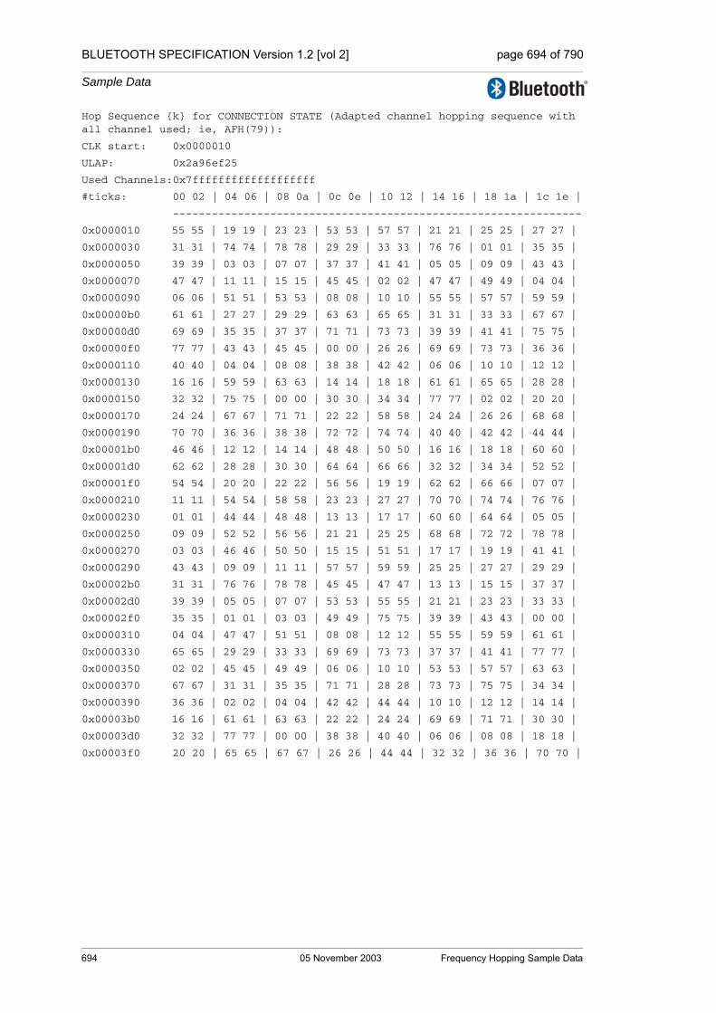
BLUETOOTH SPECIFICATION Version 1.2 [vol 2] page 694 of 790
Sample Data
Hop Sequence {k} for CONNECTION STATE (Adapted channel hopping sequence with all channel used; ie, AFH(79)):
CLK start: 0x0000010
ULAP: 0x2a96ef25
Used Channels:0x7fffffffffffffffffff
#ticks: 00 02 | 04 06 | 08 0a | 0c 0e | 10 12 | 14 16 | 18 1a | 1c 1e |
---------------------------------------------------------------
0x0000010 55 55 | 19 19 | 23 23 | 53 53 | 57 57 | 21 21 | 25 25 | 27 27 |
0x0000030 31 31 | 74 74 | 78 78 | 29 29 | 33 33 | 76 76 | 01 01 | 35 35 |
0x0000050 39 39 | 03 03 | 07 07 | 37 37 | 41 41 | 05 05 | 09 09 | 43 43 |
0x0000070 47 47 | 11 11 | 15 15 | 45 45 | 02 02 | 47 47 | 49 49 | 04 04 |
0x0000090 06 06 | 51 51 | 53 53 | 08 08 | 10 10 | 55 55 | 57 57 | 59 59 |
0x00000b0 61 61 | 27 27 | 29 29 | 63 63 | 65 65 | 31 31 | 33 33 | 67 67 |
0x00000d0 69 69 | 35 35 | 37 37 | 71 71 | 73 73 | 39 39 | 41 41 | 75 75 |
0x00000f0 77 77 | 43 43 | 45 45 | 00 00 | 26 26 | 69 69 | 73 73 | 36 36 |
0x0000110 40 40 | 04 04 | 08 08 | 38 38 | 42 42 | 06 06 | 10 10 | 12 12 |
0x0000130 16 16 | 59 59 | 63 63 | 14 14 | 18 18 | 61 61 | 65 65 | 28 28 |
0x0000150 32 32 | 75 75 | 00 00 | 30 30 | 34 34 | 77 77 | 02 02 | 20 20 |
0x0000170 24 24 | 67 67 | 71 71 | 22 22 | 58 58 | 24 24 | 26 26 | 68 68 |
0x0000190 70 70 | 36 36 | 38 38 | 72 72 | 74 74 | 40 40 | 42 42 | 44 44 |
0x00001b0 46 46 | 12 12 | 14 14 | 48 48 | 50 50 | 16 16 | 18 18 | 60 60 |
0x00001d0 62 62 | 28 28 | 30 30 | 64 64 | 66 66 | 32 32 | 34 34 | 52 52 |
0x00001f0 54 54 | 20 20 | 22 22 | 56 56 | 19 19 | 62 62 | 66 66 | 07 07 |
0x0000210 11 11 | 54 54 | 58 58 | 23 23 | 27 27 | 70 70 | 74 74 | 76 76 |
0x0000230 01 01 | 44 44 | 48 48 | 13 13 | 17 17 | 60 60 | 64 64 | 05 05 |
0x0000250 09 09 | 52 52 | 56 56 | 21 21 | 25 25 | 68 68 | 72 72 | 78 78 |
0x0000270 03 03 | 46 46 | 50 50 | 15 15 | 51 51 | 17 17 | 19 19 | 41 41 |
0x0000290 43 43 | 09 09 | 11 11 | 57 57 | 59 59 | 25 25 | 27 27 | 29 29 |
0x00002b0 31 31 | 76 76 | 78 78 | 45 45 | 47 47 | 13 13 | 15 15 | 37 37 |
0x00002d0 39 39 | 05 05 | 07 07 | 53 53 | 55 55 | 21 21 | 23 23 | 33 33 |
0x00002f0 35 35 | 01 01 | 03 03 | 49 49 | 75 75 | 39 39 | 43 43 | 00 00 |
0x0000310 04 04 | 47 47 | 51 51 | 08 08 | 12 12 | 55 55 | 59 59 | 61 61 |
0x0000330 65 65 | 29 29 | 33 33 | 69 69 | 73 73 | 37 37 | 41 41 | 77 77 |
0x0000350 02 02 | 45 45 | 49 49 | 06 06 | 10 10 | 53 53 | 57 57 | 63 63 |
0x0000370 67 67 | 31 31 | 35 35 | 71 71 | 28 28 | 73 73 | 75 75 | 34 34 |
0x0000390 36 36 | 02 02 | 04 04 | 42 42 | 44 44 | 10 10 | 12 12 | 14 14 |
0x00003b0 16 16 | 61 61 | 63 63 | 22 22 | 24 24 | 69 69 | 71 71 | 30 30 |
0x00003d0 32 32 | 77 77 | 00 00 | 38 38 | 40 40 | 06 06 | 08 08 | 18 18 |
0x00003f0 20 20 | 65 65 | 67 67 | 26 26 | 44 44 | 32 32 | 36 36 | 70 70 |
694 05 November 2003 Frequency Hopping Sample Data

BLUETOOTH SPECIFICATION Version 1.2 [vol 2] page 695 of 790
Sample Data
Hop Sequence {k} for CONNECTION STATE (Adapted channel hopping sequence with channels 0 to 21 unused):
CLK start: 0x0000010
ULAP: 0x2a96ef25
Used Channels:0x7fffffffffffffc00000
#ticks: 00 02 | 04 06 | 08 0a | 0c 0e | 10 12 | 14 16 | 18 1a | 1c 1e |
---------------------------------------------------------------
0x0000010 55 55 | 50 50 | 23 23 | 53 53 | 57 57 | 52 52 | 25 25 | 27 27 |
0x0000030 31 31 | 74 74 | 78 78 | 29 29 | 33 33 | 76 76 | 32 32 | 35 35 |
0x0000050 39 39 | 34 34 | 38 38 | 37 37 | 41 41 | 36 36 | 40 40 | 43 43 |
0x0000070 47 47 | 42 42 | 46 46 | 45 45 | 55 55 | 47 47 | 49 49 | 57 57 |
0x0000090 59 59 | 51 51 | 53 53 | 61 61 | 63 63 | 55 55 | 57 57 | 59 59 |
0x00000b0 61 61 | 27 27 | 29 29 | 63 63 | 65 65 | 31 31 | 33 33 | 67 67 |
0x00000d0 69 69 | 35 35 | 37 37 | 71 71 | 73 73 | 39 39 | 41 41 | 75 75 |
0x00000f0 77 77 | 43 43 | 45 45 | 53 53 | 26 26 | 69 69 | 73 73 | 36 36 |
0x0000110 40 40 | 57 57 | 61 61 | 38 38 | 42 42 | 59 59 | 63 63 | 65 65 |
0x0000130 69 69 | 59 59 | 63 63 | 67 67 | 71 71 | 61 61 | 65 65 | 28 28 |
0x0000150 32 32 | 75 75 | 53 53 | 30 30 | 34 34 | 77 77 | 55 55 | 73 73 |
0x0000170 24 24 | 67 67 | 71 71 | 22 22 | 58 58 | 24 24 | 26 26 | 68 68 |
0x0000190 70 70 | 36 36 | 38 38 | 72 72 | 74 74 | 40 40 | 42 42 | 44 44 |
0x00001b0 46 46 | 65 65 | 67 67 | 48 48 | 50 50 | 69 69 | 71 71 | 60 60 |
0x00001d0 62 62 | 28 28 | 30 30 | 64 64 | 66 66 | 32 32 | 34 34 | 52 52 |
0x00001f0 54 54 | 73 73 | 22 22 | 56 56 | 37 37 | 62 62 | 66 66 | 25 25 |
0x0000210 29 29 | 54 54 | 58 58 | 23 23 | 27 27 | 70 70 | 74 74 | 76 76 |
0x0000230 76 76 | 44 44 | 48 48 | 31 31 | 35 35 | 60 60 | 64 64 | 23 23 |
0x0000250 27 27 | 52 52 | 56 56 | 39 39 | 25 25 | 68 68 | 72 72 | 78 78 |
0x0000270 78 78 | 46 46 | 50 50 | 33 33 | 51 51 | 35 35 | 37 37 | 41 41 |
0x0000290 43 43 | 27 27 | 29 29 | 57 57 | 59 59 | 25 25 | 27 27 | 29 29 |
0x00002b0 31 31 | 76 76 | 78 78 | 45 45 | 47 47 | 31 31 | 33 33 | 37 37 |
0x00002d0 39 39 | 23 23 | 25 25 | 53 53 | 55 55 | 39 39 | 23 23 | 33 33 |
0x00002f0 35 35 | 76 76 | 78 78 | 49 49 | 75 75 | 39 39 | 43 43 | 40 40 |
0x0000310 44 44 | 47 47 | 51 51 | 48 48 | 52 52 | 55 55 | 59 59 | 61 61 |
0x0000330 65 65 | 29 29 | 33 33 | 69 69 | 73 73 | 37 37 | 41 41 | 77 77 |
0x0000350 42 42 | 45 45 | 49 49 | 46 46 | 50 50 | 53 53 | 57 57 | 63 63 |
0x0000370 67 67 | 31 31 | 35 35 | 71 71 | 28 28 | 73 73 | 75 75 | 34 34 |
0x0000390 36 36 | 42 42 | 44 44 | 42 42 | 44 44 | 50 50 | 52 52 | 54 54 |
0x00003b0 56 56 | 61 61 | 63 63 | 22 22 | 24 24 | 69 69 | 71 71 | 30 30 |
0x00003d0 32 32 | 77 77 | 40 40 | 38 38 | 40 40 | 46 46 | 48 48 | 58 58 |
0x00003f0 60 60 | 65 65 | 67 67 | 26 26 | 44 44 | 32 32 | 36 36 | 70 70 |
Frequency Hopping Sample Data 05 November 2003 695

BLUETOOTH SPECIFICATION Version 1.2 [vol 2] page 696 of 790
Sample Data
Hop Sequence {k} for CONNECTION STATE (Adapted channel hopping sequence with even channels used):
CLK start: 0x0000010
ULAP: 0x2a96ef25
Used Channels:0x55555555555555555555
#ticks: 00 02 | 04 06 | 08 0a | 0c 0e | 10 12 | 14 16 | 18 1a | 1c 1e |
---------------------------------------------------------------
0x0000010 52 52 | 16 16 | 20 20 | 50 50 | 54 54 | 18 18 | 22 22 | 24 24 |
0x0000030 28 28 | 74 74 | 78 78 | 26 26 | 30 30 | 76 76 | 78 78 | 32 32 |
0x0000050 36 36 | 00 00 | 04 04 | 34 34 | 38 38 | 02 02 | 06 06 | 40 40 |
0x0000070 44 44 | 08 08 | 12 12 | 42 42 | 02 02 | 44 44 | 46 46 | 04 04 |
0x0000090 06 06 | 48 48 | 50 50 | 08 08 | 10 10 | 52 52 | 54 54 | 56 56 |
0x00000b0 58 58 | 24 24 | 26 26 | 60 60 | 62 62 | 28 28 | 30 30 | 64 64 |
0x00000d0 66 66 | 32 32 | 34 34 | 68 68 | 70 70 | 36 36 | 38 38 | 72 72 |
0x00000f0 74 74 | 40 40 | 42 42 | 00 00 | 26 26 | 66 66 | 70 70 | 36 36 |
0x0000110 40 40 | 04 04 | 08 08 | 38 38 | 42 42 | 06 06 | 10 10 | 12 12 |
0x0000130 16 16 | 56 56 | 60 60 | 14 14 | 18 18 | 58 58 | 62 62 | 28 28 |
0x0000150 32 32 | 72 72 | 00 00 | 30 30 | 34 34 | 74 74 | 02 02 | 20 20 |
0x0000170 24 24 | 64 64 | 68 68 | 22 22 | 58 58 | 24 24 | 26 26 | 68 68 |
0x0000190 70 70 | 36 36 | 38 38 | 72 72 | 74 74 | 40 40 | 42 42 | 44 44 |
0x00001b0 46 46 | 12 12 | 14 14 | 48 48 | 50 50 | 16 16 | 18 18 | 60 60 |
0x00001d0 62 62 | 28 28 | 30 30 | 64 64 | 66 66 | 32 32 | 34 34 | 52 52 |
0x00001f0 54 54 | 20 20 | 22 22 | 56 56 | 14 14 | 62 62 | 66 66 | 02 02 |
0x0000210 06 06 | 54 54 | 58 58 | 18 18 | 22 22 | 70 70 | 74 74 | 76 76 |
0x0000230 76 76 | 44 44 | 48 48 | 08 08 | 12 12 | 60 60 | 64 64 | 00 00 |
0x0000250 04 04 | 52 52 | 56 56 | 16 16 | 20 20 | 68 68 | 72 72 | 78 78 |
0x0000270 78 78 | 46 46 | 50 50 | 10 10 | 46 46 | 12 12 | 14 14 | 36 36 |
0x0000290 38 38 | 04 04 | 06 06 | 52 52 | 54 54 | 20 20 | 22 22 | 24 24 |
0x00002b0 26 26 | 76 76 | 78 78 | 40 40 | 42 42 | 08 08 | 10 10 | 32 32 |
0x00002d0 34 34 | 00 00 | 02 02 | 48 48 | 50 50 | 16 16 | 18 18 | 28 28 |
0x00002f0 30 30 | 76 76 | 78 78 | 44 44 | 70 70 | 34 34 | 38 38 | 00 00 |
0x0000310 04 04 | 42 42 | 46 46 | 08 08 | 12 12 | 50 50 | 54 54 | 56 56 |
0x0000330 60 60 | 24 24 | 28 28 | 64 64 | 68 68 | 32 32 | 36 36 | 72 72 |
0x0000350 02 02 | 40 40 | 44 44 | 06 06 | 10 10 | 48 48 | 52 52 | 58 58 |
0x0000370 62 62 | 26 26 | 30 30 | 66 66 | 28 28 | 68 68 | 70 70 | 34 34 |
0x0000390 36 36 | 02 02 | 04 04 | 42 42 | 44 44 | 10 10 | 12 12 | 14 14 |
0x00003b0 16 16 | 56 56 | 58 58 | 22 22 | 24 24 | 64 64 | 66 66 | 30 30 |
0x00003d0 32 32 | 72 72 | 00 00 | 38 38 | 40 40 | 06 06 | 08 08 | 18 18 |
0x00003f0 20 20 | 60 60 | 62 62 | 26 26 | 44 44 | 32 32 | 36 36 | 70 70 |
696 05 November 2003 Frequency Hopping Sample Data

BLUETOOTH SPECIFICATION Version 1.2 [vol 2] page 697 of 790
Sample Data
Hop Sequence {k} for CONNECTION STATE (Adapted channel hopping sequence with odd channels used):
CLK start: 0x0000010
ULAP: 0x2a96ef25
Used Channels:0x2aaaaaaaaaaaaaaaaaaa
#ticks: 00 02 | 04 06 | 08 0a | 0c 0e | 10 12 | 14 16 | 18 1a | 1c 1e |
---------------------------------------------------------------
0x0000010 55 55 | 19 19 | 23 23 | 53 53 | 57 57 | 21 21 | 25 25 | 27 27 |
0x0000030 31 31 | 77 77 | 03 03 | 29 29 | 33 33 | 01 01 | 01 01 | 35 35 |
0x0000050 39 39 | 03 03 | 07 07 | 37 37 | 41 41 | 05 05 | 09 09 | 43 43 |
0x0000070 47 47 | 11 11 | 15 15 | 45 45 | 07 07 | 47 47 | 49 49 | 09 09 |
0x0000090 11 11 | 51 51 | 53 53 | 13 13 | 15 15 | 55 55 | 57 57 | 59 59 |
0x00000b0 61 61 | 27 27 | 29 29 | 63 63 | 65 65 | 31 31 | 33 33 | 67 67 |
0x00000d0 69 69 | 35 35 | 37 37 | 71 71 | 73 73 | 39 39 | 41 41 | 75 75 |
0x00000f0 77 77 | 43 43 | 45 45 | 05 05 | 31 31 | 69 69 | 73 73 | 41 41 |
0x0000110 45 45 | 09 09 | 13 13 | 43 43 | 47 47 | 11 11 | 15 15 | 17 17 |
0x0000130 21 21 | 59 59 | 63 63 | 19 19 | 23 23 | 61 61 | 65 65 | 33 33 |
0x0000150 37 37 | 75 75 | 05 05 | 35 35 | 39 39 | 77 77 | 07 07 | 25 25 |
0x0000170 29 29 | 67 67 | 71 71 | 27 27 | 63 63 | 29 29 | 31 31 | 73 73 |
0x0000190 75 75 | 41 41 | 43 43 | 77 77 | 01 01 | 45 45 | 47 47 | 49 49 |
0x00001b0 51 51 | 17 17 | 19 19 | 53 53 | 55 55 | 21 21 | 23 23 | 65 65 |
0x00001d0 67 67 | 33 33 | 35 35 | 69 69 | 71 71 | 37 37 | 39 39 | 57 57 |
0x00001f0 59 59 | 25 25 | 27 27 | 61 61 | 19 19 | 67 67 | 71 71 | 07 07 |
0x0000210 11 11 | 59 59 | 63 63 | 23 23 | 27 27 | 75 75 | 01 01 | 03 03 |
0x0000230 01 01 | 49 49 | 53 53 | 13 13 | 17 17 | 65 65 | 69 69 | 05 05 |
0x0000250 09 09 | 57 57 | 61 61 | 21 21 | 25 25 | 73 73 | 77 77 | 05 05 |
0x0000270 03 03 | 51 51 | 55 55 | 15 15 | 51 51 | 17 17 | 19 19 | 41 41 |
0x0000290 43 43 | 09 09 | 11 11 | 57 57 | 59 59 | 25 25 | 27 27 | 29 29 |
0x00002b0 31 31 | 03 03 | 05 05 | 45 45 | 47 47 | 13 13 | 15 15 | 37 37 |
0x00002d0 39 39 | 05 05 | 07 07 | 53 53 | 55 55 | 21 21 | 23 23 | 33 33 |
0x00002f0 35 35 | 01 01 | 03 03 | 49 49 | 75 75 | 39 39 | 43 43 | 07 07 |
0x0000310 11 11 | 47 47 | 51 51 | 15 15 | 19 19 | 55 55 | 59 59 | 61 61 |
0x0000330 65 65 | 29 29 | 33 33 | 69 69 | 73 73 | 37 37 | 41 41 | 77 77 |
0x0000350 09 09 | 45 45 | 49 49 | 13 13 | 17 17 | 53 53 | 57 57 | 63 63 |
0x0000370 67 67 | 31 31 | 35 35 | 71 71 | 35 35 | 73 73 | 75 75 | 41 41 |
0x0000390 43 43 | 09 09 | 11 11 | 49 49 | 51 51 | 17 17 | 19 19 | 21 21 |
0x00003b0 23 23 | 61 61 | 63 63 | 29 29 | 31 31 | 69 69 | 71 71 | 37 37 |
0x00003d0 39 39 | 77 77 | 07 07 | 45 45 | 47 47 | 13 13 | 15 15 | 25 25 |
0x00003f0 27 27 | 65 65 | 67 67 | 33 33 | 51 51 | 39 39 | 43 43 | 77 77 |
Frequency Hopping Sample Data 05 November 2003 697

BLUETOOTH SPECIFICATION Version 1.2 [vol 2] page 698 of 790
Sample Data
2.3 THIRD SET
Hop sequence {k} for PAGE SCAN/INQUIRY SCAN SUBSTATE:CLKN start: 0x0000000ULAP: 0x6587cba9#ticks: 0000 | 1000 | 2000 | 3000 | 4000 | 5000 | 6000 | 7000 |
--------------------------------------------------------0x0000000: 16 | 65 | 67 | 18 | 20 | 53 | 55 | 6 | 0x0008000: 8 | 57 | 59 | 10 | 12 | 69 | 71 | 22 | 0x0010000: 24 | 73 | 75 | 26 | 28 | 45 | 47 | 77 | 0x0018000: 0 | 49 | 51 | 2 | 4 | 61 | 63 | 14 | 0x0020000: 16 | 65 | 67 | 18 | 20 | 53 | 55 | 6 | 0x0028000: 8 | 57 | 59 | 10 | 12 | 69 | 71 | 22 | 0x0030000: 24 | 73 | 75 | 26 | 28 | 45 | 47 | 77 | 0x0038000: 0 | 49 | 51 | 2 | 4 | 61 | 63 | 14 |
Hop sequence {k} for PAGE STATE/INQUIRY SUBSTATE:CLKE start: 0x0000000ULAP: 0x6587cba9#ticks: 00 01 02 03 | 04 05 06 07 | 08 09 0a 0b | 0c 0d 0e 0f |
--------------------------------------------------------0x0000000: 00 49 36 38 | 51 02 42 40 | 04 61 44 46 | 63 14 50 48 | 0x0000010: 16 65 52 54 | 67 18 58 56 | 20 53 60 62 | 55 06 66 64 | 0x0000020: 00 49 36 38 | 51 02 42 40 | 04 61 44 46 | 63 14 50 48 | 0x0000030: 16 65 52 54 | 67 18 58 56 | 20 53 60 62 | 55 06 66 64 | ...0x0001000: 00 57 36 70 | 59 10 74 72 | 12 69 76 78 | 71 22 03 01 | 0x0001010: 24 73 05 07 | 75 26 11 09 | 28 45 13 30 | 47 77 34 32 | 0x0001020: 00 57 36 70 | 59 10 74 72 | 12 69 76 78 | 71 22 03 01 | 0x0001030: 24 73 05 07 | 75 26 11 09 | 28 45 13 30 | 47 77 34 32 | ...0x0002000: 08 57 68 70 | 51 02 42 40 | 04 61 44 46 | 63 14 50 48 | 0x0002010: 16 65 52 54 | 67 18 58 56 | 20 53 60 62 | 55 06 66 64 | 0x0002020: 08 57 68 70 | 51 02 42 40 | 04 61 44 46 | 63 14 50 48 | 0x0002030: 16 65 52 54 | 67 18 58 56 | 20 53 60 62 | 55 06 66 64 | ...0x0003000: 00 49 36 38 | 51 10 42 72 | 12 69 76 78 | 71 22 03 01 | 0x0003010: 24 73 05 07 | 75 26 11 09 | 28 45 13 30 | 47 77 34 32 | 0x0003020: 00 49 36 38 | 51 10 42 72 | 12 69 76 78 | 71 22 03 01 | 0x0003030: 24 73 05 07 | 75 26 11 09 | 28 45 13 30 | 47 77 34 32 |
Hop sequence {k} for SLAVE PAGE RESPONSE SUBSTATE:CLKN* = 0x0000010ULAP: 0x6587cba9#ticks: 00 | 02 04 | 06 08 | 0a 0c | 0e 10 | 12 14 | 16 18 | 1a 1c | 1e
----------------------------------------------------------------0x0000012: 52 | 65 54 | 67 58 | 18 56 | 20 60 | 53 62 | 55 66 | 06 64 | 08 0x0000032: 68 | 57 70 | 59 74 | 10 72 | 12 76 | 69 78 | 71 03 | 22 01 | 24 0x0000052: 05 | 73 07 | 75 11 | 26 09 | 28 13 | 45 30 | 47 34 | 77 32 | 00 0x0000072: 36 | 49 38 | 51 42 | 02 40 | 04 44 | 61 46 | 63 50 | 14 48 | 16
Hop sequence {k} for MASTER PAGE RESPONSE SUBSTATE:Offset value: 24CLKE* = 0x0000012ULAP: 0x6587cba9#ticks: 00 02 | 04 06 | 08 0a | 0c 0e | 10 12 | 14 16 | 18 1a | 1c 1e |
----------------------------------------------------------------0x0000014: 65 54 | 67 58 | 18 56 | 20 60 | 53 62 | 55 66 | 06 64 | 08 68 | 0x0000034: 57 70 | 59 74 | 10 72 | 12 76 | 69 78 | 71 03 | 22 01 | 24 05 | 0x0000054: 73 07 | 75 11 | 26 09 | 28 13 | 45 30 | 47 34 | 77 32 | 00 36 | 0x0000074: 49 38 | 51 42 | 02 40 | 04 44 | 61 46 | 63 50 | 14 48 | 16 52 |
698 05 November 2003 Frequency Hopping Sample Data

BLUETOOTH SPECIFICATION Version 1.2 [vol 2] page 699 of 790
Sample Data
Hop sequence {k} for CONNECTION STATE (Basic channel hopping sequence; ie, non-AFH):CLK start: 0x0000010ULAP: 0x6587cba9#ticks: 00 02 | 04 06 | 08 0a | 0c 0e | 10 12 | 14 16 | 18 1a | 1c 1e |
----------------------------------------------------------------0x0000010: 20 60 | 53 62 | 55 66 | 06 64 | 08 68 | 57 70 | 59 74 | 10 72 | 0x0000030: 12 76 | 69 78 | 71 03 | 22 01 | 24 05 | 73 07 | 75 11 | 26 09 | 0x0000050: 28 13 | 45 30 | 47 34 | 77 32 | 00 36 | 49 38 | 51 42 | 02 40 | 0x0000070: 04 44 | 61 46 | 63 50 | 14 48 | 50 05 | 16 07 | 20 09 | 48 11 | 0x0000090: 52 13 | 06 15 | 10 17 | 38 19 | 42 21 | 08 23 | 12 25 | 40 27 | 0x00000b0: 44 29 | 22 31 | 26 33 | 54 35 | 58 37 | 24 39 | 28 41 | 56 43 | 0x00000d0: 60 45 | 77 62 | 02 64 | 30 66 | 34 68 | 00 70 | 04 72 | 32 74 | 0x00000f0: 36 76 | 14 78 | 18 01 | 46 03 | 72 29 | 42 39 | 44 43 | 74 41 | 0x0000110: 76 45 | 46 47 | 48 51 | 78 49 | 01 53 | 50 63 | 52 67 | 03 65 | 0x0000130: 05 69 | 54 55 | 56 59 | 07 57 | 09 61 | 58 71 | 60 75 | 11 73 | 0x0000150: 13 77 | 30 15 | 32 19 | 62 17 | 64 21 | 34 31 | 36 35 | 66 33 | 0x0000170: 68 37 | 38 23 | 40 27 | 70 25 | 27 61 | 72 71 | 76 73 | 25 75 | 0x0000190: 29 77 | 78 00 | 03 02 | 31 04 | 35 06 | 01 16 | 05 18 | 33 20 | 0x00001b0: 37 22 | 07 08 | 11 10 | 39 12 | 43 14 | 09 24 | 13 26 | 41 28 | 0x00001d0: 45 30 | 62 47 | 66 49 | 15 51 | 19 53 | 64 63 | 68 65 | 17 67 | 0x00001f0: 21 69 | 70 55 | 74 57 | 23 59 | 53 22 | 35 12 | 37 28 | 67 14 | 0x0000210: 69 30 | 23 32 | 25 48 | 55 34 | 57 50 | 39 40 | 41 56 | 71 42 | 0x0000230: 73 58 | 27 36 | 29 52 | 59 38 | 61 54 | 43 44 | 45 60 | 75 46 | 0x0000250: 77 62 | 15 00 | 17 16 | 47 02 | 49 18 | 31 08 | 33 24 | 63 10 | 0x0000270: 65 26 | 19 04 | 21 20 | 51 06 | 06 54 | 65 42 | 69 58 | 18 46 | 0x0000290: 22 62 | 55 64 | 59 01 | 08 68 | 12 05 | 71 72 | 75 09 | 24 76 | 0x00002b0: 28 13 | 57 66 | 61 03 | 10 70 | 14 07 | 73 74 | 77 11 | 26 78 | 0x00002d0: 30 15 | 47 32 | 51 48 | 00 36 | 04 52 | 63 40 | 67 56 | 16 44 | 0x00002f0: 20 60 | 49 34 | 53 50 | 02 38 | 38 78 | 12 05 | 14 13 | 44 07 | 0x0000310: 46 15 | 16 17 | 18 25 | 48 19 | 50 27 | 24 33 | 26 41 | 56 35 | 0x0000330: 58 43 | 20 21 | 22 29 | 52 23 | 54 31 | 28 37 | 30 45 | 60 39 | 0x0000350: 62 47 | 00 64 | 02 72 | 32 66 | 34 74 | 08 01 | 10 09 | 40 03 | 0x0000370: 42 11 | 04 68 | 06 76 | 36 70 | 70 31 | 42 35 | 46 43 | 74 39 | 0x0000390: 78 47 | 48 49 | 52 57 | 01 53 | 05 61 | 56 65 | 60 73 | 09 69 | 0x00003b0: 13 77 | 50 51 | 54 59 | 03 55 | 07 63 | 58 67 | 62 75 | 11 71 | 0x00003d0: 15 00 | 32 17 | 36 25 | 64 21 | 68 29 | 40 33 | 44 41 | 72 37 | 0x00003f0: 76 45 | 34 19 | 38 27 | 66 23 | 11 71 | 05 18 | 07 22 | 13 20 |
Frequency Hopping Sample Data 05 November 2003 699

BLUETOOTH SPECIFICATION Version 1.2 [vol 2] page 700 of 790
Sample Data
Hop Sequence {k} for CONNECTION STATE (Adapted channel hopping sequence with all channel used; ie, AFH(79)):
CLK start: 0x0000010
ULAP: 0x6587cba9
Used Channels:0x7fffffffffffffffffff
#ticks: 00 02 | 04 06 | 08 0a | 0c 0e | 10 12 | 14 16 | 18 1a | 1c 1e |
---------------------------------------------------------------
0x0000010 20 20 | 53 53 | 55 55 | 06 06 | 08 08 | 57 57 | 59 59 | 10 10 |
0x0000030 12 12 | 69 69 | 71 71 | 22 22 | 24 24 | 73 73 | 75 75 | 26 26 |
0x0000050 28 28 | 45 45 | 47 47 | 77 77 | 00 00 | 49 49 | 51 51 | 02 02 |
0x0000070 04 04 | 61 61 | 63 63 | 14 14 | 50 50 | 16 16 | 20 20 | 48 48 |
0x0000090 52 52 | 06 06 | 10 10 | 38 38 | 42 42 | 08 08 | 12 12 | 40 40 |
0x00000b0 44 44 | 22 22 | 26 26 | 54 54 | 58 58 | 24 24 | 28 28 | 56 56 |
0x00000d0 60 60 | 77 77 | 02 02 | 30 30 | 34 34 | 00 00 | 04 04 | 32 32 |
0x00000f0 36 36 | 14 14 | 18 18 | 46 46 | 72 72 | 42 42 | 44 44 | 74 74 |
0x0000110 76 76 | 46 46 | 48 48 | 78 78 | 01 01 | 50 50 | 52 52 | 03 03 |
0x0000130 05 05 | 54 54 | 56 56 | 07 07 | 09 09 | 58 58 | 60 60 | 11 11 |
0x0000150 13 13 | 30 30 | 32 32 | 62 62 | 64 64 | 34 34 | 36 36 | 66 66 |
0x0000170 68 68 | 38 38 | 40 40 | 70 70 | 27 27 | 72 72 | 76 76 | 25 25 |
0x0000190 29 29 | 78 78 | 03 03 | 31 31 | 35 35 | 01 01 | 05 05 | 33 33 |
0x00001b0 37 37 | 07 07 | 11 11 | 39 39 | 43 43 | 09 09 | 13 13 | 41 41 |
0x00001d0 45 45 | 62 62 | 66 66 | 15 15 | 19 19 | 64 64 | 68 68 | 17 17 |
0x00001f0 21 21 | 70 70 | 74 74 | 23 23 | 53 53 | 35 35 | 37 37 | 67 67 |
0x0000210 69 69 | 23 23 | 25 25 | 55 55 | 57 57 | 39 39 | 41 41 | 71 71 |
0x0000230 73 73 | 27 27 | 29 29 | 59 59 | 61 61 | 43 43 | 45 45 | 75 75 |
0x0000250 77 77 | 15 15 | 17 17 | 47 47 | 49 49 | 31 31 | 33 33 | 63 63 |
0x0000270 65 65 | 19 19 | 21 21 | 51 51 | 06 06 | 65 65 | 69 69 | 18 18 |
0x0000290 22 22 | 55 55 | 59 59 | 08 08 | 12 12 | 71 71 | 75 75 | 24 24 |
0x00002b0 28 28 | 57 57 | 61 61 | 10 10 | 14 14 | 73 73 | 77 77 | 26 26 |
0x00002d0 30 30 | 47 47 | 51 51 | 00 00 | 04 04 | 63 63 | 67 67 | 16 16 |
0x00002f0 20 20 | 49 49 | 53 53 | 02 02 | 38 38 | 12 12 | 14 14 | 44 44 |
0x0000310 46 46 | 16 16 | 18 18 | 48 48 | 50 50 | 24 24 | 26 26 | 56 56 |
0x0000330 58 58 | 20 20 | 22 22 | 52 52 | 54 54 | 28 28 | 30 30 | 60 60 |
0x0000350 62 62 | 00 00 | 02 02 | 32 32 | 34 34 | 08 08 | 10 10 | 40 40 |
0x0000370 42 42 | 04 04 | 06 06 | 36 36 | 70 70 | 42 42 | 46 46 | 74 74 |
0x0000390 78 78 | 48 48 | 52 52 | 01 01 | 05 05 | 56 56 | 60 60 | 09 09 |
0x00003b0 13 13 | 50 50 | 54 54 | 03 03 | 07 07 | 58 58 | 62 62 | 11 11 |
0x00003d0 15 15 | 32 32 | 36 36 | 64 64 | 68 68 | 40 40 | 44 44 | 72 72 |
0x00003f0 76 76 | 34 34 | 38 38 | 66 66 | 11 11 | 05 05 | 07 07 | 13 13 |
700 05 November 2003 Frequency Hopping Sample Data

BLUETOOTH SPECIFICATION Version 1.2 [vol 2] page 701 of 790
Sample Data
Hop Sequence {k} for CONNECTION STATE (Adapted channel hopping sequence with channels 0 to 21 unused):
CLK start: 0x0000010
ULAP: 0x6587cba9
Used Channels:0x7fffffffffffffc00000
#ticks: 00 02 | 04 06 | 08 0a | 0c 0e | 10 12 | 14 16 | 18 1a | 1c 1e |
---------------------------------------------------------------
0x0000010 29 29 | 53 53 | 55 55 | 72 72 | 74 74 | 57 57 | 59 59 | 76 76 |
0x0000030 78 78 | 69 69 | 71 71 | 22 22 | 24 24 | 73 73 | 75 75 | 26 26 |
0x0000050 28 28 | 45 45 | 47 47 | 77 77 | 66 66 | 49 49 | 51 51 | 68 68 |
0x0000070 70 70 | 61 61 | 63 63 | 23 23 | 50 50 | 25 25 | 29 29 | 48 48 |
0x0000090 52 52 | 72 72 | 76 76 | 38 38 | 42 42 | 74 74 | 78 78 | 40 40 |
0x00000b0 44 44 | 22 22 | 26 26 | 54 54 | 58 58 | 24 24 | 28 28 | 56 56 |
0x00000d0 60 60 | 77 77 | 68 68 | 30 30 | 34 34 | 66 66 | 70 70 | 32 32 |
0x00000f0 36 36 | 23 23 | 27 27 | 46 46 | 72 72 | 42 42 | 44 44 | 74 74 |
0x0000110 76 76 | 46 46 | 48 48 | 78 78 | 32 32 | 50 50 | 52 52 | 34 34 |
0x0000130 36 36 | 54 54 | 56 56 | 38 38 | 40 40 | 58 58 | 60 60 | 42 42 |
0x0000150 44 44 | 30 30 | 32 32 | 62 62 | 64 64 | 34 34 | 36 36 | 66 66 |
0x0000170 68 68 | 38 38 | 40 40 | 70 70 | 27 27 | 72 72 | 76 76 | 25 25 |
0x0000190 29 29 | 78 78 | 34 34 | 31 31 | 35 35 | 32 32 | 36 36 | 33 33 |
0x00001b0 37 37 | 38 38 | 42 42 | 39 39 | 43 43 | 40 40 | 44 44 | 41 41 |
0x00001d0 45 45 | 62 62 | 66 66 | 46 46 | 50 50 | 64 64 | 68 68 | 48 48 |
0x00001f0 52 52 | 70 70 | 74 74 | 23 23 | 53 53 | 35 35 | 37 37 | 67 67 |
0x0000210 69 69 | 23 23 | 25 25 | 55 55 | 57 57 | 39 39 | 41 41 | 71 71 |
0x0000230 73 73 | 27 27 | 29 29 | 59 59 | 61 61 | 43 43 | 45 45 | 75 75 |
0x0000250 77 77 | 46 46 | 48 48 | 47 47 | 49 49 | 31 31 | 33 33 | 63 63 |
0x0000270 65 65 | 50 50 | 52 52 | 51 51 | 59 59 | 65 65 | 69 69 | 71 71 |
0x0000290 22 22 | 55 55 | 59 59 | 61 61 | 65 65 | 71 71 | 75 75 | 24 24 |
0x00002b0 28 28 | 57 57 | 61 61 | 63 63 | 67 67 | 73 73 | 77 77 | 26 26 |
0x00002d0 30 30 | 47 47 | 51 51 | 53 53 | 57 57 | 63 63 | 67 67 | 69 69 |
0x00002f0 73 73 | 49 49 | 53 53 | 55 55 | 38 38 | 65 65 | 67 67 | 44 44 |
0x0000310 46 46 | 69 69 | 71 71 | 48 48 | 50 50 | 24 24 | 26 26 | 56 56 |
0x0000330 58 58 | 73 73 | 22 22 | 52 52 | 54 54 | 28 28 | 30 30 | 60 60 |
0x0000350 62 62 | 53 53 | 55 55 | 32 32 | 34 34 | 61 61 | 63 63 | 40 40 |
0x0000370 42 42 | 57 57 | 59 59 | 36 36 | 70 70 | 42 42 | 46 46 | 74 74 |
0x0000390 78 78 | 48 48 | 52 52 | 76 76 | 23 23 | 56 56 | 60 60 | 27 27 |
0x00003b0 31 31 | 50 50 | 54 54 | 78 78 | 25 25 | 58 58 | 62 62 | 29 29 |
0x00003d0 33 33 | 32 32 | 36 36 | 64 64 | 68 68 | 40 40 | 44 44 | 72 72 |
0x00003f0 76 76 | 34 34 | 38 38 | 66 66 | 29 29 | 23 23 | 25 25 | 31 31 |
Frequency Hopping Sample Data 05 November 2003 701
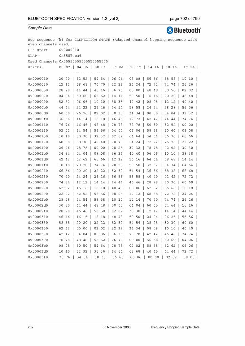
BLUETOOTH SPECIFICATION Version 1.2 [vol 2] page 702 of 790
Sample Data
Hop Sequence {k} for CONNECTION STATE (Adapted channel hopping sequence with even channels used):
CLK start: 0x0000010
ULAP: 0x6587cba9
Used Channels:0x55555555555555555555
#ticks: 00 02 | 04 06 | 08 0a | 0c 0e | 10 12 | 14 16 | 18 1a | 1c 1e |
---------------------------------------------------------------
0x0000010 20 20 | 52 52 | 54 54 | 06 06 | 08 08 | 56 56 | 58 58 | 10 10 |
0x0000030 12 12 | 68 68 | 70 70 | 22 22 | 24 24 | 72 72 | 74 74 | 26 26 |
0x0000050 28 28 | 44 44 | 46 46 | 76 76 | 00 00 | 48 48 | 50 50 | 02 02 |
0x0000070 04 04 | 60 60 | 62 62 | 14 14 | 50 50 | 16 16 | 20 20 | 48 48 |
0x0000090 52 52 | 06 06 | 10 10 | 38 38 | 42 42 | 08 08 | 12 12 | 40 40 |
0x00000b0 44 44 | 22 22 | 26 26 | 54 54 | 58 58 | 24 24 | 28 28 | 56 56 |
0x00000d0 60 60 | 76 76 | 02 02 | 30 30 | 34 34 | 00 00 | 04 04 | 32 32 |
0x00000f0 36 36 | 14 14 | 18 18 | 46 46 | 72 72 | 42 42 | 44 44 | 74 74 |
0x0000110 76 76 | 46 46 | 48 48 | 78 78 | 78 78 | 50 50 | 52 52 | 00 00 |
0x0000130 02 02 | 54 54 | 56 56 | 04 04 | 06 06 | 58 58 | 60 60 | 08 08 |
0x0000150 10 10 | 30 30 | 32 32 | 62 62 | 64 64 | 34 34 | 36 36 | 66 66 |
0x0000170 68 68 | 38 38 | 40 40 | 70 70 | 24 24 | 72 72 | 76 76 | 22 22 |
0x0000190 26 26 | 78 78 | 00 00 | 28 28 | 32 32 | 78 78 | 02 02 | 30 30 |
0x00001b0 34 34 | 04 04 | 08 08 | 36 36 | 40 40 | 06 06 | 10 10 | 38 38 |
0x00001d0 42 42 | 62 62 | 66 66 | 12 12 | 16 16 | 64 64 | 68 68 | 14 14 |
0x00001f0 18 18 | 70 70 | 74 74 | 20 20 | 50 50 | 32 32 | 34 34 | 64 64 |
0x0000210 66 66 | 20 20 | 22 22 | 52 52 | 54 54 | 36 36 | 38 38 | 68 68 |
0x0000230 70 70 | 24 24 | 26 26 | 56 56 | 58 58 | 40 40 | 42 42 | 72 72 |
0x0000250 74 74 | 12 12 | 14 14 | 44 44 | 46 46 | 28 28 | 30 30 | 60 60 |
0x0000270 62 62 | 16 16 | 18 18 | 48 48 | 06 06 | 62 62 | 66 66 | 18 18 |
0x0000290 22 22 | 52 52 | 56 56 | 08 08 | 12 12 | 68 68 | 72 72 | 24 24 |
0x00002b0 28 28 | 54 54 | 58 58 | 10 10 | 14 14 | 70 70 | 74 74 | 26 26 |
0x00002d0 30 30 | 44 44 | 48 48 | 00 00 | 04 04 | 60 60 | 64 64 | 16 16 |
0x00002f0 20 20 | 46 46 | 50 50 | 02 02 | 38 38 | 12 12 | 14 14 | 44 44 |
0x0000310 46 46 | 16 16 | 18 18 | 48 48 | 50 50 | 24 24 | 26 26 | 56 56 |
0x0000330 58 58 | 20 20 | 22 22 | 52 52 | 54 54 | 28 28 | 30 30 | 60 60 |
0x0000350 62 62 | 00 00 | 02 02 | 32 32 | 34 34 | 08 08 | 10 10 | 40 40 |
0x0000370 42 42 | 04 04 | 06 06 | 36 36 | 70 70 | 42 42 | 46 46 | 74 74 |
0x0000390 78 78 | 48 48 | 52 52 | 76 76 | 00 00 | 56 56 | 60 60 | 04 04 |
0x00003b0 08 08 | 50 50 | 54 54 | 78 78 | 02 02 | 58 58 | 62 62 | 06 06 |
0x00003d0 10 10 | 32 32 | 36 36 | 64 64 | 68 68 | 40 40 | 44 44 | 72 72 |
0x00003f0 76 76 | 34 34 | 38 38 | 66 66 | 06 06 | 00 00 | 02 02 | 08 08 |
702 05 November 2003 Frequency Hopping Sample Data
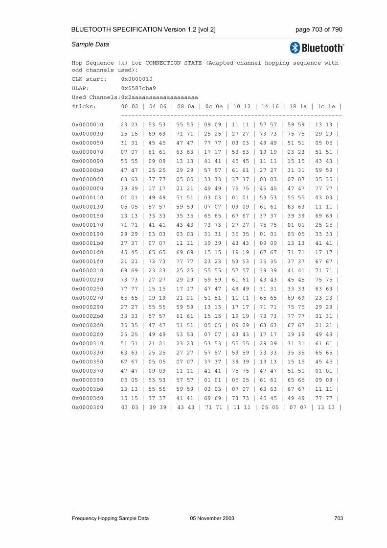
BLUETOOTH SPECIFICATION Version 1.2 [vol 2] page 703 of 790
Sample Data
Hop Sequence {k} for CONNECTION STATE (Adapted channel hopping sequence with odd channels used):
CLK start: 0x0000010
ULAP: 0x6587cba9
Used Channels:0x2aaaaaaaaaaaaaaaaaaa
#ticks: 00 02 | 04 06 | 08 0a | 0c 0e | 10 12 | 14 16 | 18 1a | 1c 1e |
---------------------------------------------------------------
0x0000010 23 23 | 53 53 | 55 55 | 09 09 | 11 11 | 57 57 | 59 59 | 13 13 |
0x0000030 15 15 | 69 69 | 71 71 | 25 25 | 27 27 | 73 73 | 75 75 | 29 29 |
0x0000050 31 31 | 45 45 | 47 47 | 77 77 | 03 03 | 49 49 | 51 51 | 05 05 |
0x0000070 07 07 | 61 61 | 63 63 | 17 17 | 53 53 | 19 19 | 23 23 | 51 51 |
0x0000090 55 55 | 09 09 | 13 13 | 41 41 | 45 45 | 11 11 | 15 15 | 43 43 |
0x00000b0 47 47 | 25 25 | 29 29 | 57 57 | 61 61 | 27 27 | 31 31 | 59 59 |
0x00000d0 63 63 | 77 77 | 05 05 | 33 33 | 37 37 | 03 03 | 07 07 | 35 35 |
0x00000f0 39 39 | 17 17 | 21 21 | 49 49 | 75 75 | 45 45 | 47 47 | 77 77 |
0x0000110 01 01 | 49 49 | 51 51 | 03 03 | 01 01 | 53 53 | 55 55 | 03 03 |
0x0000130 05 05 | 57 57 | 59 59 | 07 07 | 09 09 | 61 61 | 63 63 | 11 11 |
0x0000150 13 13 | 33 33 | 35 35 | 65 65 | 67 67 | 37 37 | 39 39 | 69 69 |
0x0000170 71 71 | 41 41 | 43 43 | 73 73 | 27 27 | 75 75 | 01 01 | 25 25 |
0x0000190 29 29 | 03 03 | 03 03 | 31 31 | 35 35 | 01 01 | 05 05 | 33 33 |
0x00001b0 37 37 | 07 07 | 11 11 | 39 39 | 43 43 | 09 09 | 13 13 | 41 41 |
0x00001d0 45 45 | 65 65 | 69 69 | 15 15 | 19 19 | 67 67 | 71 71 | 17 17 |
0x00001f0 21 21 | 73 73 | 77 77 | 23 23 | 53 53 | 35 35 | 37 37 | 67 67 |
0x0000210 69 69 | 23 23 | 25 25 | 55 55 | 57 57 | 39 39 | 41 41 | 71 71 |
0x0000230 73 73 | 27 27 | 29 29 | 59 59 | 61 61 | 43 43 | 45 45 | 75 75 |
0x0000250 77 77 | 15 15 | 17 17 | 47 47 | 49 49 | 31 31 | 33 33 | 63 63 |
0x0000270 65 65 | 19 19 | 21 21 | 51 51 | 11 11 | 65 65 | 69 69 | 23 23 |
0x0000290 27 27 | 55 55 | 59 59 | 13 13 | 17 17 | 71 71 | 75 75 | 29 29 |
0x00002b0 33 33 | 57 57 | 61 61 | 15 15 | 19 19 | 73 73 | 77 77 | 31 31 |
0x00002d0 35 35 | 47 47 | 51 51 | 05 05 | 09 09 | 63 63 | 67 67 | 21 21 |
0x00002f0 25 25 | 49 49 | 53 53 | 07 07 | 43 43 | 17 17 | 19 19 | 49 49 |
0x0000310 51 51 | 21 21 | 23 23 | 53 53 | 55 55 | 29 29 | 31 31 | 61 61 |
0x0000330 63 63 | 25 25 | 27 27 | 57 57 | 59 59 | 33 33 | 35 35 | 65 65 |
0x0000350 67 67 | 05 05 | 07 07 | 37 37 | 39 39 | 13 13 | 15 15 | 45 45 |
0x0000370 47 47 | 09 09 | 11 11 | 41 41 | 75 75 | 47 47 | 51 51 | 01 01 |
0x0000390 05 05 | 53 53 | 57 57 | 01 01 | 05 05 | 61 61 | 65 65 | 09 09 |
0x00003b0 13 13 | 55 55 | 59 59 | 03 03 | 07 07 | 63 63 | 67 67 | 11 11 |
0x00003d0 15 15 | 37 37 | 41 41 | 69 69 | 73 73 | 45 45 | 49 49 | 77 77 |
0x00003f0 03 03 | 39 39 | 43 43 | 71 71 | 11 11 | 05 05 | 07 07 | 13 13 |
Frequency Hopping Sample Data 05 November 2003 703

BLUETOOTH SPECIFICATION Version 1.2 [vol 2] page 704 of 790
Sample Data
704 05 November 2003 Frequency Hopping Sample Data
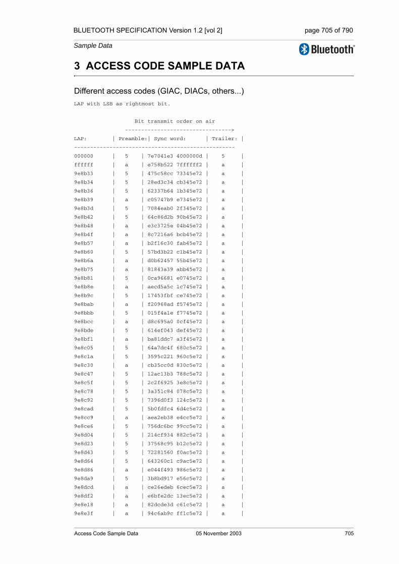
BLUETOOTH SPECIFICATION Version 1.2 [vol 2] page 705 of 790
Sample Data
3 ACCESS CODE SAMPLE DATA
Different access codes (GIAC, DIACs, others...)LAP with LSB as rightmost bit.
Bit transmit order on air
--------------------------------->
LAP: | Preamble:| Sync word: | Trailer: |
--------------------------------------------------
000000 | 5 | 7e7041e3 4000000d | 5 |
ffffff | a | e758b522 7ffffff2 | a |
9e8b33 | 5 | 475c58cc 73345e72 | a |
9e8b34 | 5 | 28ed3c34 cb345e72 | a |
9e8b36 | 5 | 62337b64 1b345e72 | a |
9e8b39 | a | c05747b9 e7345e72 | a |
9e8b3d | 5 | 7084eab0 2f345e72 | a |
9e8b42 | 5 | 64c86d2b 90b45e72 | a |
9e8b48 | a | e3c3725e 04b45e72 | a |
9e8b4f | a | 8c7216a6 bcb45e72 | a |
9e8b57 | a | b2f16c30 fab45e72 | a |
9e8b60 | 5 | 57bd3b22 c1b45e72 | a |
9e8b6a | a | d0b62457 55b45e72 | a |
9e8b75 | a | 81843a39 abb45e72 | a |
9e8b81 | 5 | 0ca96681 e0745e72 | a |
9e8b8e | a | aecd5a5c 1c745e72 | a |
9e8b9c | 5 | 17453fbf ce745e72 | a |
9e8bab | a | f20968ad f5745e72 | a |
9e8bbb | 5 | 015f4a1e f7745e72 | a |
9e8bcc | a | d8c695a0 0cf45e72 | a |
9e8bde | 5 | 614ef043 def45e72 | a |
9e8bf1 | a | ba81ddc7 a3f45e72 | a |
9e8c05 | 5 | 64a7dc4f 680c5e72 | a |
9e8c1a | 5 | 3595c221 960c5e72 | a |
9e8c30 | a | cb35cc0d 830c5e72 | a |
9e8c47 | 5 | 12ac13b3 788c5e72 | a |
9e8c5f | 5 | 2c2f6925 3e8c5e72 | a |
9e8c78 | 5 | 3a351c84 078c5e72 | a |
9e8c92 | 5 | 7396d0f3 124c5e72 | a |
9e8cad | 5 | 5b0fdfc4 6d4c5e72 | a |
9e8cc9 | a | aea2eb38 e4cc5e72 | a |
9e8ce6 | 5 | 756dc6bc 99cc5e72 | a |
9e8d04 | 5 | 214cf934 882c5e72 | a |
9e8d23 | 5 | 37568c95 b12c5e72 | a |
9e8d43 | 5 | 72281560 f0ac5e72 | a |
9e8d64 | 5 | 643260c1 c9ac5e72 | a |
9e8d86 | a | e044f493 986c5e72 | a |
9e8da9 | 5 | 3b8bd917 e56c5e72 | a |
9e8dcd | a | ce26edeb 6cec5e72 | a |
9e8df2 | a | e6bfe2dc 13ec5e72 | a |
9e8e18 | a | 82dcde3d c61c5e72 | a |
9e8e3f | a | 94c6ab9c ff1c5e72 | a |
Access Code Sample Data 05 November 2003 705
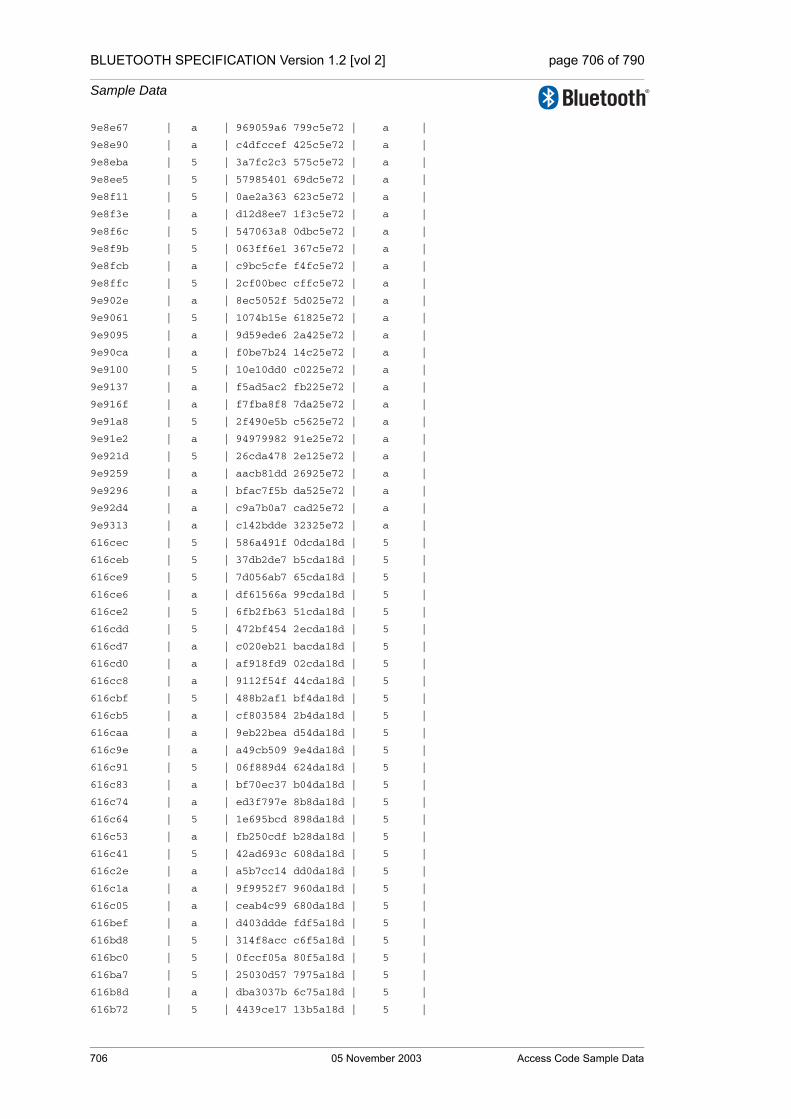
BLUETOOTH SPECIFICATION Version 1.2 [vol 2] page 706 of 790
Sample Data
9e8e67 | a | 969059a6 799c5e72 | a |
9e8e90 | a | c4dfccef 425c5e72 | a |
9e8eba | 5 | 3a7fc2c3 575c5e72 | a |
9e8ee5 | 5 | 57985401 69dc5e72 | a |
9e8f11 | 5 | 0ae2a363 623c5e72 | a |
9e8f3e | a | d12d8ee7 1f3c5e72 | a |
9e8f6c | 5 | 547063a8 0dbc5e72 | a |
9e8f9b | 5 | 063ff6e1 367c5e72 | a |
9e8fcb | a | c9bc5cfe f4fc5e72 | a |
9e8ffc | 5 | 2cf00bec cffc5e72 | a |
9e902e | a | 8ec5052f 5d025e72 | a |
9e9061 | 5 | 1074b15e 61825e72 | a |
9e9095 | a | 9d59ede6 2a425e72 | a |
9e90ca | a | f0be7b24 14c25e72 | a |
9e9100 | 5 | 10e10dd0 c0225e72 | a |
9e9137 | a | f5ad5ac2 fb225e72 | a |
9e916f | a | f7fba8f8 7da25e72 | a |
9e91a8 | 5 | 2f490e5b c5625e72 | a |
9e91e2 | a | 94979982 91e25e72 | a |
9e921d | 5 | 26cda478 2e125e72 | a |
9e9259 | a | aacb81dd 26925e72 | a |
9e9296 | a | bfac7f5b da525e72 | a |
9e92d4 | a | c9a7b0a7 cad25e72 | a |
9e9313 | a | c142bdde 32325e72 | a |
616cec | 5 | 586a491f 0dcda18d | 5 |
616ceb | 5 | 37db2de7 b5cda18d | 5 |
616ce9 | 5 | 7d056ab7 65cda18d | 5 |
616ce6 | a | df61566a 99cda18d | 5 |
616ce2 | 5 | 6fb2fb63 51cda18d | 5 |
616cdd | 5 | 472bf454 2ecda18d | 5 |
616cd7 | a | c020eb21 bacda18d | 5 |
616cd0 | a | af918fd9 02cda18d | 5 |
616cc8 | a | 9112f54f 44cda18d | 5 |
616cbf | 5 | 488b2af1 bf4da18d | 5 |
616cb5 | a | cf803584 2b4da18d | 5 |
616caa | a | 9eb22bea d54da18d | 5 |
616c9e | a | a49cb509 9e4da18d | 5 |
616c91 | 5 | 06f889d4 624da18d | 5 |
616c83 | a | bf70ec37 b04da18d | 5 |
616c74 | a | ed3f797e 8b8da18d | 5 |
616c64 | 5 | 1e695bcd 898da18d | 5 |
616c53 | a | fb250cdf b28da18d | 5 |
616c41 | 5 | 42ad693c 608da18d | 5 |
616c2e | a | a5b7cc14 dd0da18d | 5 |
616c1a | a | 9f9952f7 960da18d | 5 |
616c05 | a | ceab4c99 680da18d | 5 |
616bef | a | d403ddde fdf5a18d | 5 |
616bd8 | 5 | 314f8acc c6f5a18d | 5 |
616bc0 | 5 | 0fccf05a 80f5a18d | 5 |
616ba7 | 5 | 25030d57 7975a18d | 5 |
616b8d | a | dba3037b 6c75a18d | 5 |
616b72 | 5 | 4439ce17 13b5a18d | 5 |
706 05 November 2003 Access Code Sample Data

BLUETOOTH SPECIFICATION Version 1.2 [vol 2] page 707 of 790
Sample Data
616b56 | a | 8d417247 5ab5a18d | 5 |
616b39 | 5 | 6a5bd76f e735a18d | 5 |
616b1b | 5 | 592e8166 b635a18d | 5 |
616afc | 5 | 28609d46 cfd5a18d | 5 |
616adc | 5 | 51cb8c1f 4ed5a18d | 5 |
616abb | 5 | 7b047112 b755a18d | 5 |
616a99 | 5 | 4871271b e655a18d | 5 |
616a76 | 5 | 24bdc8c4 9b95a18d | 5 |
616a52 | a | edc57494 d295a18d | 5 |
616a2d | a | f989f30f 6d15a18d | 5 |
616a07 | 5 | 0729fd23 7815a18d | 5 |
6169e0 | a | 8bf0ba4f 81e5a18d | 5 |
6169b8 | a | 89a64875 0765a18d | 5 |
61698f | 5 | 6cea1f67 3c65a18d | 5 |
616965 | 5 | 2549d310 29a5a18d | 5 |
61693a | 5 | 48ae45d2 1725a18d | 5 |
61690e | 5 | 7280db31 5c25a18d | 5 |
6168e1 | a | ce1b9f34 61c5a18d | 5 |
6168b3 | 5 | 4b46727b 7345a18d | 5 |
616884 | a | ae0a2569 4845a18d | 5 |
616854 | a | ea5fc581 4a85a18d | 5 |
616823 | 5 | 33c61a3f b105a18d | 5 |
6167f1 | a | c49fb8c5 63f9a18d | 5 |
6167be | 5 | 5a2e0cb4 5f79a18d | 5 |
61678a | 5 | 60009257 1479a18d | 5 |
616755 | a | 86314e62 eab9a18d | 5 |
61671f | 5 | 3defd9bb be39a18d | 5 |
6166e8 | a | bff7e728 c5d9a18d | 5 |
6166b0 | a | bda11512 4359a18d | 5 |
616677 | 5 | 6513b3b1 fb99a18d | 5 |
61663d | a | decd2468 af19a18d | 5 |
616602 | a | f6542b5f d019a18d | 5 |
6165c6 | a | dc44b49b d8e9a18d | 5 |
616589 | 5 | 42f500ea e469a18d | 5 |
61654b | a | bf2885e1 34a9a18d | 5 |
61650c | a | ec4c69b5 4c29a18d | 5 |
Access Code Sample Data 05 November 2003 707

BLUETOOTH SPECIFICATION Version 1.2 [vol 2] page 708 of 790
Sample Data
708 05 November 2003 Access Code Sample Data
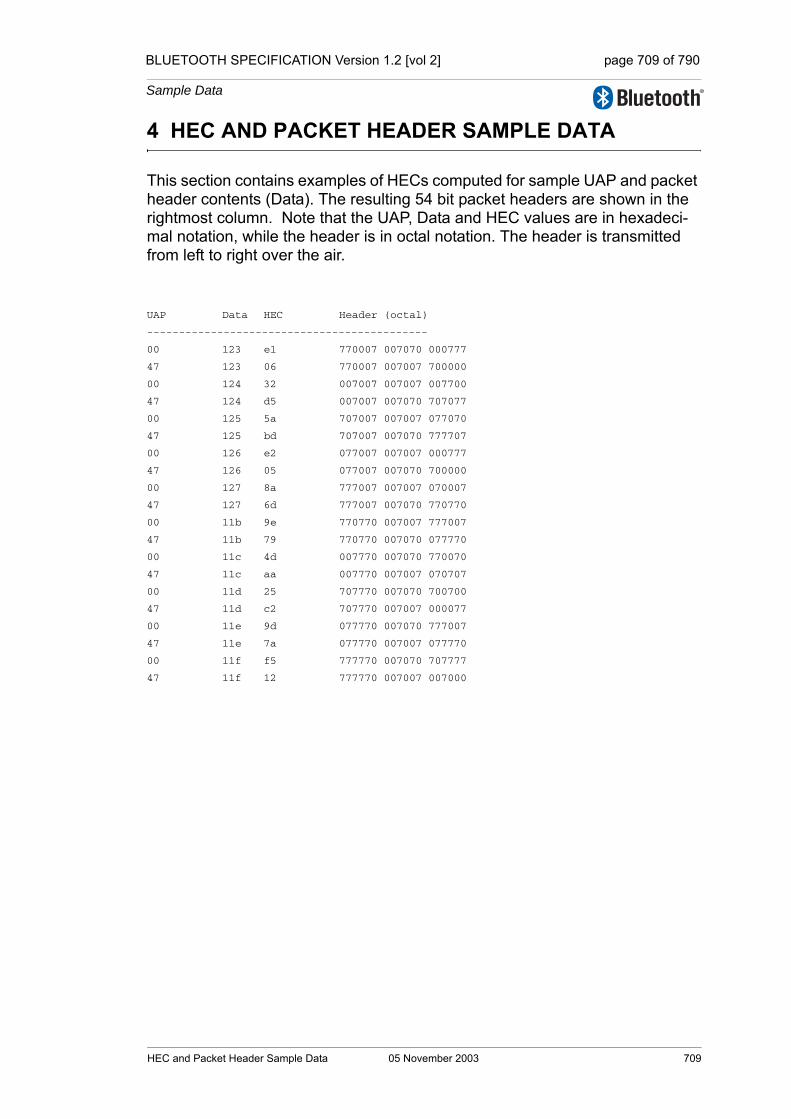
BLUETOOTH SPECIFICATION Version 1.2 [vol 2] page 709 of 790
Sample Data
4 HEC AND PACKET HEADER SAMPLE DATA
This section contains examples of HECs computed for sample UAP and packet header contents (Data). The resulting 54 bit packet headers are shown in the rightmost column. Note that the UAP, Data and HEC values are in hexadeci-mal notation, while the header is in octal notation. The header is transmitted from left to right over the air.
UAP Data HEC Header (octal)
--------------------------------------------
00 123 e1 770007 007070 000777
47 123 06 770007 007007 700000
00 124 32 007007 007007 007700
47 124 d5 007007 007070 707077
00 125 5a 707007 007007 077070
47 125 bd 707007 007070 777707
00 126 e2 077007 007007 000777
47 126 05 077007 007070 700000
00 127 8a 777007 007007 070007
47 127 6d 777007 007070 770770
00 11b 9e 770770 007007 777007
47 11b 79 770770 007070 077770
00 11c 4d 007770 007070 770070
47 11c aa 007770 007007 070707
00 11d 25 707770 007070 700700
47 11d c2 707770 007007 000077
00 11e 9d 077770 007070 777007
47 11e 7a 077770 007007 077770
00 11f f5 777770 007070 707777
47 11f 12 777770 007007 007000
HEC and Packet Header Sample Data 05 November 2003 709

BLUETOOTH SPECIFICATION Version 1.2 [vol 2] page 710 of 790
Sample Data
710 05 November 2003 HEC and Packet Header Sample Data
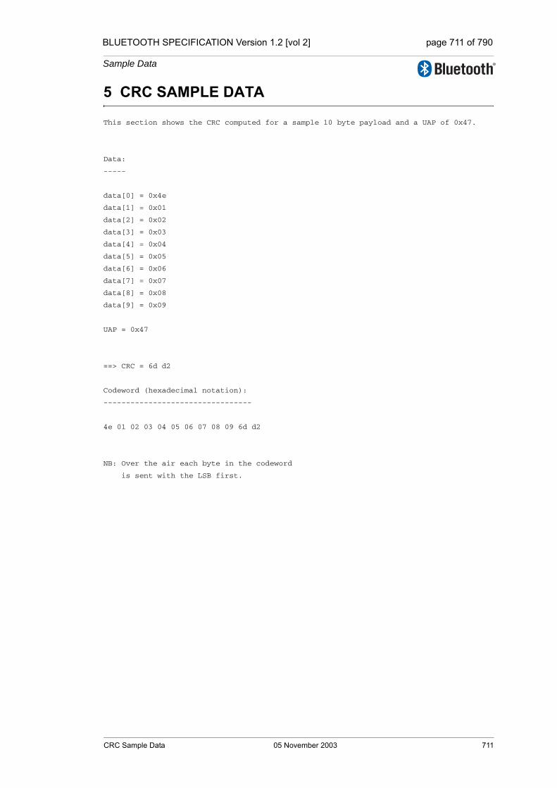
BLUETOOTH SPECIFICATION Version 1.2 [vol 2] page 711 of 790
Sample Data
5 CRC SAMPLE DATA
This section shows the CRC computed for a sample 10 byte payload and a UAP of 0x47.
Data:
-----
data[0] = 0x4e
data[1] = 0x01
data[2] = 0x02
data[3] = 0x03
data[4] = 0x04
data[5] = 0x05
data[6] = 0x06
data[7] = 0x07
data[8] = 0x08
data[9] = 0x09
UAP = 0x47
==> CRC = 6d d2
Codeword (hexadecimal notation):
---------------------------------
4e 01 02 03 04 05 06 07 08 09 6d d2
NB: Over the air each byte in the codeword
is sent with the LSB first.
CRC Sample Data 05 November 2003 711

BLUETOOTH SPECIFICATION Version 1.2 [vol 2] page 712 of 790
Sample Data
712 05 November 2003 CRC Sample Data
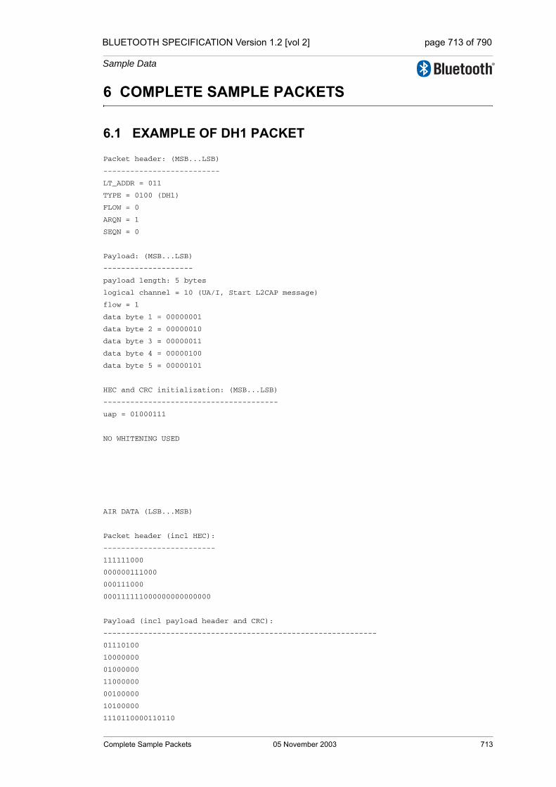
BLUETOOTH SPECIFICATION Version 1.2 [vol 2] page 713 of 790
Sample Data
6 COMPLETE SAMPLE PACKETS
6.1 EXAMPLE OF DH1 PACKET
Packet header: (MSB...LSB)
--------------------------
LT_ADDR = 011
TYPE = 0100 (DH1)
FLOW = 0
ARQN = 1
SEQN = 0
Payload: (MSB...LSB)
--------------------
payload length: 5 bytes
logical channel = 10 (UA/I, Start L2CAP message)
flow = 1
data byte 1 = 00000001
data byte 2 = 00000010
data byte 3 = 00000011
data byte 4 = 00000100
data byte 5 = 00000101
HEC and CRC initialization: (MSB...LSB)
---------------------------------------
uap = 01000111
NO WHITENING USED
AIR DATA (LSB...MSB)
Packet header (incl HEC):
-------------------------
111111000
000000111000
000111000
000111111000000000000000
Payload (incl payload header and CRC):
-------------------------------------------------------------
01110100
10000000
01000000
11000000
00100000
10100000
1110110000110110
Complete Sample Packets 05 November 2003 713
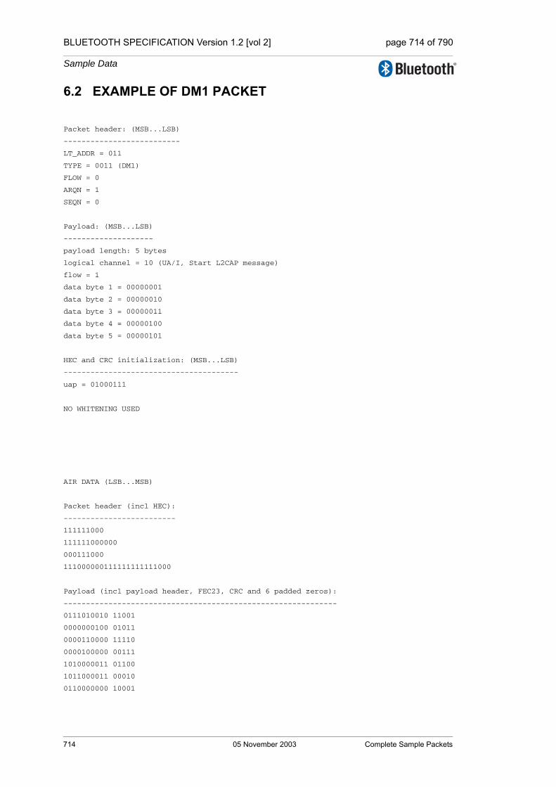
BLUETOOTH SPECIFICATION Version 1.2 [vol 2] page 714 of 790
Sample Data
6.2 EXAMPLE OF DM1 PACKET
Packet header: (MSB...LSB)
--------------------------
LT_ADDR = 011
TYPE = 0011 (DM1)
FLOW = 0
ARQN = 1
SEQN = 0
Payload: (MSB...LSB)
--------------------
payload length: 5 bytes
logical channel = 10 (UA/I, Start L2CAP message)
flow = 1
data byte 1 = 00000001
data byte 2 = 00000010
data byte 3 = 00000011
data byte 4 = 00000100
data byte 5 = 00000101
HEC and CRC initialization: (MSB...LSB)
---------------------------------------
uap = 01000111
NO WHITENING USED
AIR DATA (LSB...MSB)
Packet header (incl HEC):
-------------------------
111111000
111111000000
000111000
111000000111111111111000
Payload (incl payload header, FEC23, CRC and 6 padded zeros):
-------------------------------------------------------------
0111010010 11001
0000000100 01011
0000110000 11110
0000100000 00111
1010000011 01100
1011000011 00010
0110000000 10001
714 05 November 2003 Complete Sample Packets

BLUETOOTH SPECIFICATION Version 1.2 [vol 2] page 715 of 790
Sample Data
7 WHITENING SEQUENCE SAMPLE DATA
This section shows the output of the whitening sequence generator.
Whitening Whitening
Sequence LFSR
(=D7) D7.....D0
-----------------------
1 1111111
1 1101111
1 1001111
0 0001111
0 0011110
0 0111100
1 1111000
1 1100001
1 1010011
0 0110111
1 1101110
1 1001101
0 0001011
0 0010110
0 0101100
1 1011000
0 0100001
1 1000010
0 0010101
0 0101010
1 1010100
0 0111001
1 1110010
1 1110101
1 1111011
1 1100111
1 1011111
0 0101111
1 1011110
0 0101101
1 1011010
0 0100101
1 1001010
0 0000101
0 0001010
0 0010100
0 0101000
1 1010000
0 0110001
1 1100010
1 1010101
0 0111011
1 1110110
Whitening Sequence Sample Data 05 November 2003 715
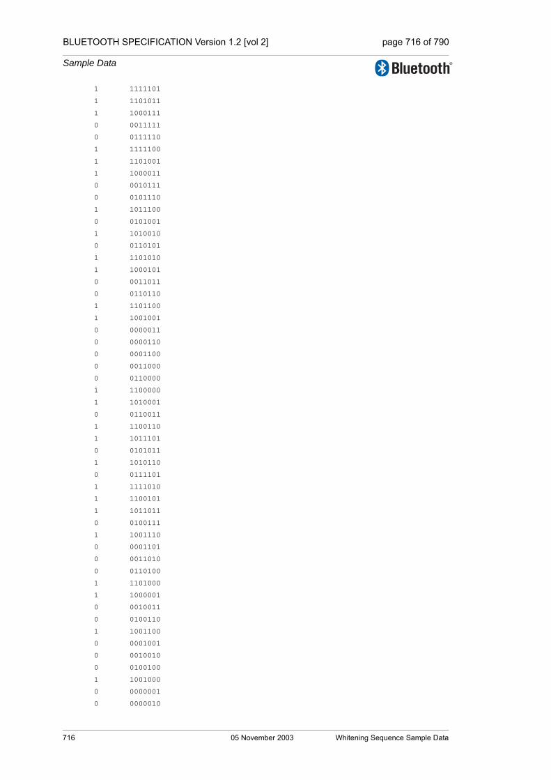
BLUETOOTH SPECIFICATION Version 1.2 [vol 2] page 716 of 790
Sample Data
1 1111101
1 1101011
1 1000111
0 0011111
0 0111110
1 1111100
1 1101001
1 1000011
0 0010111
0 0101110
1 1011100
0 0101001
1 1010010
0 0110101
1 1101010
1 1000101
0 0011011
0 0110110
1 1101100
1 1001001
0 0000011
0 0000110
0 0001100
0 0011000
0 0110000
1 1100000
1 1010001
0 0110011
1 1100110
1 1011101
0 0101011
1 1010110
0 0111101
1 1111010
1 1100101
1 1011011
0 0100111
1 1001110
0 0001101
0 0011010
0 0110100
1 1101000
1 1000001
0 0010011
0 0100110
1 1001100
0 0001001
0 0010010
0 0100100
1 1001000
0 0000001
0 0000010
716 05 November 2003 Whitening Sequence Sample Data

BLUETOOTH SPECIFICATION Version 1.2 [vol 2] page 717 of 790
Sample Data
0 0000100
0 0001000
0 0010000
0 0100000
1 1000000
0 0010001
0 0100010
1 1000100
0 0011001
0 0110010
1 1100100
1 1011001
0 0100011
1 1000110
0 0011101
0 0111010
1 1110100
1 1111001
1 1100011
1 1010111
0 0111111
1 1111110
1 1101101
1 1001011
0 0000111
0 0001110
0 0011100
0 0111000
1 1110000
1 1110001
1 1110011
1 1110111
1 1111111
Whitening Sequence Sample Data 05 November 2003 717

BLUETOOTH SPECIFICATION Version 1.2 [vol 2] page 718 of 790
Sample Data
718 05 November 2003 Whitening Sequence Sample Data

BLUETOOTH SPECIFICATION Version 1.2 [vol 2] page 719 of 790
Sample Data
8 FEC SAMPLE DATA
================================================
Rate 2/3 FEC -- (15,10) Shortened Hamming Code
================================================
Data is in hexadecimal notation, the codewords are in binary notation. The codeword bits are sent from left to right over the air interface. The space in the codeword indicates the start of parity bits.
Data: Codeword:
0x001 1000000000 11010
0x002 0100000000 01101
0x004 0010000000 11100
0x008 0001000000 01110
0x010 0000100000 00111
0x020 0000010000 11001
0x040 0000001000 10110
0x080 0000000100 01011
0x100 0000000010 11111
0x200 0000000001 10101
FEC Sample Data 05 November 2003 719

BLUETOOTH SPECIFICATION Version 1.2 [vol 2] page 720 of 790
Sample Data
720 05 November 2003 FEC Sample Data

BLUETOOTH SPECIFICATION Version 1.2 [vol 2] page 721 of 790
Sample Data
9 ENCRYPTION KEY SAMPLE DATA
Explanation:
For the sections 9.1 - 9.5, the hexadecimal sample data is written with the least significant byte at the leftmost position and the most significant byte at the rightmost position. Within each byte, the least significant bit (LSB) is at the rightmost position and the most significant bit (MSB) is at the leftmost position Thus, a line reading:
aco: 48afcdd4bd40fef76693b113
means aco[0]=0x48, ac[1]=0xaf, ..., aco[11]=0x13. The LSB of aco[11] is ‘1’ and the MSB of aco[11] is ‘0’.
Key [ i]: denotes the ith sub-key in Ar or A'r;round r: denotes the input to the rth round;added ->: denotes the input to round 3 in
A'r after adding original input (of round 1).
9.1 FOUR TESTS OF E1
rand :00000000000000000000000000000000
address :000000000000
key :00000000000000000000000000000000
round 1:00000000000000000000000000000000
Key [ 1]:00000000000000000000000000000000
Key [ 2]:4697b1baa3b7100ac537b3c95a28ac64
round 2:78d19f9307d2476a523ec7a8a026042a
Key [ 3]:ecabaac66795580df89af66e66dc053d
Key [ 4]:8ac3d8896ae9364943bfebd4969b68a0
round 3:600265247668dda0e81c07bbb30ed503
Key [ 5]:5d57921fd5715cbb22c1be7bbc996394
Key [ 6]:2a61b8343219fdfb1740e6511d41448f
round 4:d7552ef7cc9dbde568d80c2215bc4277
Key [ 7]:dd0480dee731d67f01a2f739da6f23ca
Key [ 8]:3ad01cd1303e12a1cd0fe0a8af82592c
round 5:fb06bef32b52ab8f2a4f2b6ef7f6d0cd
Key [ 9]:7dadb2efc287ce75061302904f2e7233
Key [10]:c08dcfa981e2c4272f6c7a9f52e11538
round 6:b46b711ebb3cf69e847a75f0ab884bdd
Key [11]:fc2042c708e409555e8c147660ffdfd7
Key [12]:fa0b21001af9a6b9e89e624cd99150d2
round 7:c585f308ff19404294f06b292e978994
Key [13]:18b40784ea5ba4c80ecb48694b4e9c35
Key [14]:454d54e5253c0c4a8b3fcca7db6baef4
round 8:2665fadb13acf952bf74b4ab12264b9f
Key [15]:2df37c6d9db52674f29353b0f011ed83
Key [16]:b60316733b1e8e70bd861b477e2456f1
Key [17]:884697b1baa3b7100ac537b3c95a28ac
Encryption Key Sample Data 05 November 2003 721

BLUETOOTH SPECIFICATION Version 1.2 [vol 2] page 722 of 790
Sample Data
round 1:158ffe43352085e8a5ec7a88e1ff2ba8
Key [ 1]:e9e5dfc1b3a79583e9e5dfc1b3a79583
Key [ 2]:7595bf57e0632c59f435c16697d4c864
round 2:0b5cc75febcdf7827ca29ec0901b6b5b
Key [ 3]:e31b96afcc75d286ef0ae257cbbc05b7
Key [ 4]:0d2a27b471bc0108c6263aff9d9b3b6b
round 3:e4278526c8429211f7f2f0016220aef4
added ->:f1b68365fd6217f952de6a89831fd95c
Key [ 5]:98d1eb5773cf59d75d3b17b3bc37c191
Key [ 6]:fd2b79282408ddd4ea0aa7511133336f
round 4:d0304ad18337f86040145d27aa5c8153
Key [ 7]:331227756638a41d57b0f7e071ee2a98
Key [ 8]:aa0dd8cc68b406533d0f1d64aabacf20
round 5:84db909d213bb0172b8b6aaf71bf1472
Key [ 9]:669291b0752e63f806fce76f10e119c8
Key [10]:ef8bdd46be8ee0277e9b78adef1ec154
round 6:f835f52921e903dfa762f1df5abd7f95
Key [11]:f3902eb06dc409cfd78384624964bf51
Key [12]:7d72702b21f97984a721c99b0498239d
round 7:ae6c0b4bb09f25c6a5d9788a31b605d1
Key [13]:532e60bceaf902c52a06c2c283ecfa32
Key [14]:181715e5192efb2a64129668cf5d9dd4
round 8:744a6235b86cc0b853cc9f74f6b65311
Key [15]:83017c1434342d4290e961578790f451
Key [16]:2603532f365604646ff65803795ccce5
Key [17]:882f7c907b565ea58dae1c928a0dcf41
sres :056c0fe6
aco :48afcdd4bd40fef76693b113
-----------------------------------------
rand :bc3f30689647c8d7c5a03ca80a91eceb
address :7ca89b233c2d
key :159dd9f43fc3d328efba0cd8a861fa57
round 1:bc3f30689647c8d7c5a03ca80a91eceb
Key [ 1]:159dd9f43fc3d328efba0cd8a861fa57
Key [ 2]:326558b3c15551899a97790e65ff669e
round 2:3e950edf197615638cc19c09f8fedc9b
Key [ 3]:62e879b65b9f53bbfbd020c624b1d682
Key [ 4]:73415f30bac8ab61f410adc9442992db
round 3:6a7640791cb536678936c5ecd4ae5a73
Key [ 5]:5093cfa1d31c1c48acd76df030ea3c31
Key [ 6]:0b4acc2b8f1f694fc7bd91f4a70f3009
round 4:fca2c022a577e2ffb2aa007589693ec7
Key [ 7]:2ca43fc817947804ecff148d50d6f6c6
Key [ 8]:3fcd73524b533e00b7f7825bea2040a4
round 5:e97f8ea4ed1a6f4a36ffc179dc6bb563
Key [ 9]:6c67bec76ae8c8cc4d289f69436d3506
Key [10]:95ed95ee8cb97e61d75848464bffb379
round 6:38b07261d7340d028749de1773a415c7
Key [11]:ff566c1fc6b9da9ac502514550f3e9d2
Key [12]:ab5ce3f5c887d0f49b87e0d380e12f47
round 7:58241f1aed7c1c3e047d724331a0b774
Key [13]:a2cab6f95eac7d655dbe84a6cd4c47f5
722 05 November 2003 Encryption Key Sample Data

BLUETOOTH SPECIFICATION Version 1.2 [vol 2] page 723 of 790
Sample Data
Key [14]:f5caff88af0af8c42a20b5bbd2c8b460
round 8:3d1aaeff53c0910de63b9788b13c490f
Key [15]:185099c1131cf97001e2f36fda415025
Key [16]:a0ebb82676bc75e8378b189eff3f6b1d
Key [17]:cf5b348aaee27ae332b4f1bfa10289a6
round 1:2e4b417b9a2a9cfd7d8417d9a6a556eb
Key [ 1]:fe78b835f26468ab069fd3991b086fda
Key [ 2]:095c5a51c6fa6d3ac1d57fa19aa382bd
round 2:b8bca81d6bb45af9d92beadd9300f5ed
Key [ 3]:1af866df817fd9f4ec00bc704192cffc
Key [ 4]:f4a8a059c1f575f076f5fbb24bf16590
round 3:351aa16dec2c3a4787080249ed323eae
added ->:1b65e2167656d6bafa8c19904bd79445
Key [ 5]:8c9d18d9356a9954d341b4286e88ea1f
Key [ 6]:5c958d370102c9881bf753e69c7da029
round 4:2ce8fef47dda6a5bee74372e33e478a2
Key [ 7]:7eb2985c3697429fbe0da334bb51f795
Key [ 8]:af900f4b63a1138e2874bfb7c628b7b8
round 5:572787f563e1643c1c862b7555637fb4
Key [ 9]:834c8588dd8f3d4f31117a488420d69b
Key [10]:bc2b9b81c15d9a80262f3f48e9045895
round 6:16b4968c5d02853c3a43aa4cdb5f26ac
Key [11]:f08608c9e39ad3147cba61327919c958
Key [12]:2d4131decf4fa3a959084714a9e85c11
round 7:10e4120c7cccef9dd4ba4e6da8571b01
Key [13]:c934fd319c4a2b5361fa8eef05ae9572
Key [14]:4904c17aa47868e40471007cde3a97c0
round 8:f9081772498fed41b6ffd72b71fcf6c6
Key [15]:ea5e28687e97fa3f833401c86e6053ef
Key [16]:1168f58252c4ecfccafbdb3af857b9f2
Key [17]:b3440f69ef951b78b5cbd6866275301b
sres :8d5205c5
aco :3ed75df4abd9af638d144e94
-----------------------------------------
rand :0891caee063f5da1809577ff94ccdcfb
address :c62f19f6ce98
key :45298d06e46bac21421ddfbed94c032b
round 1:0891caee063f5da1809577ff94ccdcfb
Key [ 1]:45298d06e46bac21421ddfbed94c032b
Key [ 2]:8f03e1e1fe1c191cad35a897bc400597
round 2:1c6ca013480a685c1b28e0317f7167e1
Key [ 3]:4f2ce3a092dde854ef496c8126a69e8e
Key [ 4]:968caee2ac6d7008c07283daec67f2f2
round 3:06b4915f5fcc1fc551a52048f0af8a26
Key [ 5]:ab0d5c31f94259a6bf85ee2d22edf56c
Key [ 6]:dfb74855c0085ce73dc17b84bfd50a92
round 4:077a92b040acc86e6e0a877db197a167
Key [ 7]:8f888952662b3db00d4e904e7ea53b5d
Key [ 8]:5e18bfcc07799b0132db88cd6042f599
round 5:7204881fb300914825fdc863e8ceadf3
Key [ 9]:bfca91ad9bd3d1a06c582b1d5512dddf
Key [10]:a88bc477e3fa1d5a59b5e6cf793c7a41
Encryption Key Sample Data 05 November 2003 723
BLUETOOTH SPECIFICATION Version 1.2 [vol 2] page 724 of 790
Sample Data
round 6:27031131d86cea2d747deb4f756143aa
Key [11]:f3cfb8dac8aea2a6a8ef95af3a2a2767
Key [12]:77beb90670c5300b03aa2b2232d3d40c
round 7:fc8c13d49149b1ce8d86f96e44a00065
Key [13]:b578373650af36a06e19fe335d726d32
Key [14]:6bcee918c7d0d24dfdf42237fcf99d53
round 8:04ef5f5a7ddf846cda0a07782fc23866
Key [15]:399f158241eb3e079f45d7b96490e7ea
Key [16]:1bcfbe98ecde2add52aa63ea79fb917a
Key [17]:ee8bc03ec08722bc2b075492873374af
round 1:d989d7a40cde7032d17b52f8117b69d5
Key [ 1]:2ecc6cc797cc41a2ab02007f6af396ae
Key [ 2]:acfaef7609c12567d537ae1cf9dc2198
round 2:8e76eb9a29b2ad5eea790db97aee37c1
Key [ 3]:079c8ff9b73d428df879906a0b87a6c8
Key [ 4]:19f2710baf403a494193d201f3a8c439
round 3:346bb7c35b2539676375aafe3af69089
added ->:edf48e675703a955b2f0fc062b71f95c
Key [ 5]:d623a6498f915cb2c8002765247b2f5a
Key [ 6]:900109093319bc30108b3d9434a77a72
round 4:fafb6c1f3ebbd2477be2da49dd923f69
Key [ 7]:e28e2ee6e72e7f4e5b5c11f10d204228
Key [ 8]:8e455cd11f8b9073a2dfa5413c7a4bc5
round 5:7c72230df588060a3cf920f9b0a08f06
Key [ 9]:28afb26e2c7a64238c41cefc16c53e74
Key [10]:d08dcafc2096395ba0d2dddd0e471f4d
round 6:55991df991db26ff00073a12baa3031d
Key [11]:fcffdcc3ad8faae091a7055b934f87c1
Key [12]:f8df082d77060252c02d91e55bd6a7d6
round 7:70ec682ff864375f63701fa4f6be5377
Key [13]:bef3706e523d708e8a44147d7508bc35
Key [14]:3e98ab283ca2422d56a56cf8b06caeb3
round 8:172f12ec933da85504b4ea5c90f8f0ea
Key [15]:87ad9625d06645d22598dd5ef811ea2c
Key [16]:8bd3db0cc8168009e5da90877e13a36f
Key [17]:0e74631d813a8351ac7039b348c41b42
sres :00507e5f
aco :2a5f19fbf60907e69f39ca9f
-----------------------------------------
rand :0ecd61782b4128480c05dc45542b1b8c
address :f428f0e624b3
key :35949a914225fabad91995d226de1d92
round 1:0ecd61782b4128480c05dc45542b1b8c
Key [ 1]:35949a914225fabad91995d226de1d92
Key [ 2]:ea6b3dcccc8ee5d88de349fa5010404f
round 2:8935e2e263fbc4b9302cabdfc06bce3e
Key [ 3]:920f3a0f2543ce535d4e7f25ad80648a
Key [ 4]:ad47227edf9c6874e80ba80ebb95d2c9
round 3:b4c8b878675f184a0c72f3dab51f8f05
Key [ 5]:81a941ca7202b5e884ae8fa493ecac3d
Key [ 6]:bcde1520bee3660e86ce2f0fb78b9157
round 4:77ced9f2fc42bdd5c6312b87fc2377c5
724 05 November 2003 Encryption Key Sample Data

BLUETOOTH SPECIFICATION Version 1.2 [vol 2] page 725 of 790
Sample Data
Key [ 7]:c8eee7423d7c6efa75ecec0d2cd969d3
Key [ 8]:910b3f838a02ed441fbe863a02b4a1d0
round 5:fe28e8056f3004d60bb207e628b39cf2
Key [ 9]:56c647c1e865eb078348962ae070972d
Key [10]:883965da77ca5812d8104e2b640aec0d
round 6:1f2ba92259d9e88101518f145a33840f
Key [11]:61d4cb7e4f8868a283327806a9bd8d4d
Key [12]:9f57de3a3ff310e21dc1e696ce060304
round 7:cc9b5d0218d29037e88475152ebebb2f
Key [13]:7aa1d8adc1aeed7127ef9a18f6eb2d8e
Key [14]:b4db9da3bf865912acd14904c7f7785d
round 8:b04d352bedc02682e4a7f59d7cda1dba
Key [15]:a13d7141ef1f6c7d867e3d175467381b
Key [16]:08b2bc058e50d6141cdd566a307e1acc
Key [17]:057b2b4b4be5dc0ac49e50489b8006c9
round 1:5cfacc773bae995cd7f1b81e7c9ec7df
Key [ 1]:1e717950f5828f3930fe4a9395858815
Key [ 2]:d1623369b733d98bbc894f75866c544c
round 2:d571ffa21d9daa797b1a0a3c962fc64c
Key [ 3]:4abf27664ae364cc8a7e5bcf88214cc4
Key [ 4]:2aaedda8dc4933dd6aeaf6e5c0d5a482
round 3:e17c8e498a00f125bf654c938c23f36d
added ->:bd765a3eb1ae8a796856048df0c1bab2
Key [ 5]:bc7f8ab2d86000f47b1946cc8d7a7a2b
Key [ 6]:6b28544cb13ec6c5d98470df2cf900b7
round 4:a9727c26f2f06bd9920e83c8605dcd76
Key [ 7]:1be840d9107f2c9523f66bb19f5464a1
Key [ 8]:61d6fb1aa2f0c2b26fb2a3d6de8c177c
round 5:aeff751f146eab7e4626b2e2c9e2fb39
Key [ 9]:adabfc82570c568a233173099f23f4c2
Key [10]:b7df6b55ad266c0f1ff7452101f59101
round 6:cf412b95f454d5185e67ca671892e5bd
Key [11]:8e04a7282a2950dcbaea28f300e22de3
Key [12]:21362c114433e29bda3e4d51f803b0cf
round 7:16165722fe4e07ef88f8056b17d89567
Key [13]:710c8fd5bb3cbb5f132a7061de518bd9
Key [14]:0791de7334f4c87285809343f3ead3bd
round 8:28854cd6ad4a3c572b15490d4b81bc3f
Key [15]:4f47f0e5629a674bfcd13770eb3a3bd9
Key [16]:58a6d9a16a284cc0aead2126c79608a1
Key [17]:a564082a0a98399f43f535fd5cefad34
sres :80e5629c
aco :a6fe4dcde3924611d3cc6ba1
=========================================
Encryption Key Sample Data 05 November 2003 725
BLUETOOTH SPECIFICATION Version 1.2 [vol 2] page 726 of 790
Sample Data
9.2 FOUR TESTS OF E21
rand :00000000000000000000000000000000
address :000000000000
round 1:00000000000000000000000000000000
Key [ 1]:00000000000000000000000000000006
Key [ 2]:4697b1baa3b7100ac537b3c95a28dc94
round 2:98611307ab76bbde9a86af1ce8cad412
Key [ 3]:ecabaac66795580df89af66e665d863d
Key [ 4]:8ac3d8896ae9364943bfebd4a2a768a0
round 3:820999ad2e6618f4b578974beeedf9e7
added ->:820999ad2e6618f4b578974beeedf9e7
Key [ 5]:5d57921fd5715cbb22c1bedb1c996394
Key [ 6]:2a61b8343219fdfb1740e9541d41448f
round 4:acd6edec87581ac22dbdc64ea4ced3a2
Key [ 7]:dd0480dee731d67f01ba0f39da6f23ca
Key [ 8]:3ad01cd1303e12a18dcfe0a8af82592c
round 5:1c7798732f09fbfe25795a4a2fbc93c2
Key [ 9]:7dadb2efc287ce7b0c1302904f2e7233
Key [10]:c08dcfa981e2f4572f6c7a9f52e11538
round 6:c05b88b56aa70e9c40c79bb81cd911bd
Key [11]:fc2042c708658a555e8c147660ffdfd7
Key [12]:fa0b21002605a6b9e89e624cd99150d2
round 7:abacc71b481c84c798d1bdf3d62f7e20
Key [13]:18b407e44a5ba4c80ecb48694b4e9c35
Key [14]:454d57e8253c0c4a8b3fcca7db6baef4
round 8:e8204e1183ae85cf19edb2c86215b700
Key [15]:2d0b946d9db52674f29353b0f011ed83
Key [16]:76c316733b1e8e70bd861b477e2456f1
Key [17]:8e4697b1baa3b7100ac537b3c95a28ac
Ka :d14ca028545ec262cee700e39b5c39ee
-----------------------------------------
rand :2dd9a550343191304013b2d7e1189d09
address :cac4364303b6
round 1:cac4364303b6cac4364303b6cac43643
Key [ 1]:2dd9a550343191304013b2d7e1189d0f
Key [ 2]:14c4335b2c43910c5dcc71d81a14242b
round 2:e169f788aad45a9011f11db5270b1277
Key [ 3]:55bfb712cba168d1a48f6e74cd9f4388
Key [ 4]:2a2b3aacca695caef2821b0fb48cc253
round 3:540f9c76652e92c44987c617035037bf
added ->:9ed3d23566e45c007fcac9a1c9146dfc
Key [ 5]:a06aab22d9a287384042976b4b6b00ee
Key [ 6]:c229d054bb72e8eb230e6dcdb32d16b7
round 4:83659a41675f7171ea57909dc5a79ab4
Key [ 7]:23c4812ab1905ddf77dedaed4105649a
Key [ 8]:40d87e272a7a1554ae2e85e3638cdf52
round 5:0b9382d0ed4f2fccdbb69d0db7b130a4
Key [ 9]:bdc064c6a39f6b84fe40db359f62a3c4
Key [10]:58228db841ce3cee983aa721f36aa1b9
round 6:c6ebda0f8f489792f09c189568226c1f
Key [11]:a815bacd6fa747a0d4f52883ac63ebe7
726 05 November 2003 Encryption Key Sample Data

BLUETOOTH SPECIFICATION Version 1.2 [vol 2] page 727 of 790
Sample Data
Key [12]:a9ce513b38ea006c333ecaaefcf1d0f8
round 7:75a8aba07e69c9065bcd831c40115116
Key [13]:3635e074792d4122130e5b824e52cd60
Key [14]:511bdb61bb28de72a5d794bffbf407df
round 8:57a6e279dcb764cf7dd6a749dd60c735
Key [15]:a32f5f21044b6744b6d913b13cdb4c0a
Key [16]:9722bbaeef281496ef8c23a9d41e92f4
Key [17]:807370560ad7e8a13a054a65a03b4049
Ka :e62f8bac609139b3999aedbc9d228042
-----------------------------------------
rand :dab3cffe9d5739d1b7bf4a667ae5ee24
address :02f8fd4cd661
round 1:02f8fd4cd66102f8fd4cd66102f8fd4c
Key [ 1]:dab3cffe9d5739d1b7bf4a667ae5ee22
Key [ 2]:e315a8a65d809ec7c289e69c899fbdcc
round 2:ef85ff081b8709405e19f3e275cec7dc
Key [ 3]:df6a119bb50945fc8a3394e7216448f3
Key [ 4]:87fe86fb0d58b5dd0fb3b6b1dab51d07
round 3:aa25c21bf577d92dd97381e3e9edcc54
added ->:a81dbf5723d8dbd524bf5782ebe5c918
Key [ 5]:36cc253c506c0021c91fac9d8c469e90
Key [ 6]:d5fda00f113e303809b7f7d78a1a2b0e
round 4:9e69ce9b53caec3990894d2baed41e0d
Key [ 7]:c14b5edc10cabf16bc2a2ba4a8ae1e40
Key [ 8]:74c6131afc8dce7e11b03b1ea8610c16
round 5:a5460fa8cedca48a14fd02209e01f02e
Key [ 9]:346cfc553c6cbc9713edb55f4dcbc96c
Key [10]:bddf027cb059d58f0509f8963e9bdec6
round 6:92b33f11eadcacc5a43dd05f13d334dd
Key [11]:8eb9e040c36c4c0b4a7fd3dd354d53c4
Key [12]:c6ffecdd5e135b20879b9dfa4b34bf51
round 7:fb0541aa5e5df1a61c51aef606eb5a41
Key [13]:bf12f5a6ba08dfc4fda4bdfc68c997d9
Key [14]:37c4656b9215f3c959ea688fb64ad327
round 8:f0bbd2b94ae374346730581fc77a9c98
Key [15]:e87bb0d86bf421ea4f779a8eee3a866c
Key [16]:faa471e934fd415ae4c0113ec7f0a5ad
Key [17]:95204a80b8400e49db7cf6fd2fd40d9a
Ka :b0376d0a9b338c2e133c32b69cb816b3
-----------------------------------------
rand :13ecad08ad63c37f8a54dc56e82f4dc1
address :9846c5ead4d9
round 1:9846c5ead4d99846c5ead4d99846c5ea
Key [ 1]:13ecad08ad63c37f8a54dc56e82f4dc7
Key [ 2]:ad04f127bed50b5e671d6510d392eaed
round 2:97374e18cdd0a6f7a5aa49d1ac875c84
Key [ 3]:57ad159e5774fa222f2f3039b9cd5101
Key [ 4]:9a1e9e1068fede02ef90496e25fd8e79
round 3:9dd3260373edd9d5f4e774826b88fd2d
added ->:0519ebe9a7c6719331d1485bf3cec2c7
Key [ 5]:378dce167db62920b0b392f7cfca316e
Key [ 6]:db4277795c87286faee6c9e9a6b71a93
Encryption Key Sample Data 05 November 2003 727

BLUETOOTH SPECIFICATION Version 1.2 [vol 2] page 728 of 790
Sample Data
round 4:40ec6563450299ac4e120d88672504d6
Key [ 7]:ec01aa2f5a8a793b36c1bb858d254380
Key [ 8]:2921a66cfa5bf74ac535424564830e98
round 5:57287bbb041bd6a56c2bd931ed410cd4
Key [ 9]:07018e45aab61b3c3726ee3d57dbd5f6
Key [10]:627381f0fa4c02b0c7d3e7dfbffc3333
round 6:66affa66a8dcd36e36bf6c3f1c6a276e
Key [11]:33b57c925bd5551999f716e138efbe79
Key [12]:a6dc7f9aa95bcc9243aebd12608f657a
round 7:450e65184fd8c72c578d5cdecb286743
Key [13]:a6a6db00fd8c72a28ea57ea542f6e102
Key [14]:dcf3377daeb2e24e61f0ad6620951c1f
round 8:e5eb180b519a4e673f21b7c4f4573f3d
Key [15]:621240b9506b462a7fa250da41844626
Key [16]:ae297810f01f43dc35756cd119ee73d6
Key [17]:b959835ec2501ad3894f8b8f1f4257f9
Ka :5b61e83ad04d23e9d1c698851fa30447
=========================================
9.3 THREE TESTS OF E22
(for K_master and overlay generation)
rand :001de169248850245a5f7cc7f0d6d633
PIN :d5a51083a04a1971f18649ea8b79311a
round 1:001de169248850245a5f7cc7f0d6d623
Key [ 1]:d5a51083a04a1971f18649ea8b79311a
Key [ 2]:7317cdbff57f9b99f9810a2525b17cc7
round 2:5f05c143347b59acae3cb002db23830f
Key [ 3]:f08bd258adf1d4ae4a54d8ccb26220b2
Key [ 4]:91046cbb4ccc43db18d6dd36ca7313eb
round 3:c8f3e3300541a25b6ac5a80c3105f3c4
added ->:c810c45921c9f27f302424cbc1dbc9e7
Key [ 5]:67fb2336f4d9f069da58d11c82f6bd95
Key [ 6]:4fed702c75bd72c0d3d8f38707134c50
round 4:bd5e0c3a97fa55b91a3bbbf306ebb978
Key [ 7]:41c947f80cdc0464c50aa89070af314c
Key [ 8]:680eecfa8daf41c7109c9a5cb1f26d75
round 5:21c1a762c3cc33e75ce8976a73983087
Key [ 9]:6e33fbd94d00ff8f72e8a7a0d2cebc4c
Key [10]:f4d726054c6b948add99fabb5733ddc3
round 6:56d0df484345582f6b574a449ba155eb
Key [11]:4eda2425546a24cac790f49ef2453b53
Key [12]:cf2213624ed1510408a5a3e00b7333df
round 7:120cf9963fe9ff22993f7fdf9600d9b8
Key [13]:d04b1a25b0b8fec946d5ecfa626d04c9
Key [14]:01e5611b0f0e140bdb64585fd3ae5269
round 8:a6337400ad8cb47fefb91332f5cb2713
Key [15]:f15b2dc433f534f61bf718770a3698b1
Key [16]:f990d0273d8ea2b9e0b45917a781c720
Key [17]:f41b3cc13d4301297bb6bdfcb3e5a1dd
Ka :539e4f2732e5ae2de1e0401f0813bd0d
728 05 November 2003 Encryption Key Sample Data

BLUETOOTH SPECIFICATION Version 1.2 [vol 2] page 729 of 790
Sample Data
-----------------------------------------
rand :67ed56bfcf99825f0c6b349369da30ab
PIN :7885b515e84b1f082cc499976f1725ce
round 1:67ed56bfcf99825f0c6b349369da30bb
Key [ 1]:7885b515e84b1f082cc499976f1725ce
Key [ 2]:72445901fdaf506beb036f4412512248
round 2:6b160b66a1f6c26c1f3432f463ef5aa1
Key [ 3]:59f0e4982e97633e5e7fd133af8f2c5b
Key [ 4]:b4946ec77a41bf7c729d191e33d458ab
round 3:3f22046c964c3e5ca2a26ec9a76a9f67
added ->:580f5ad359e5c003ae0da25ace44cfdc
Key [ 5]:eb0b839f97bdf534183210678520bbef
Key [ 6]:cff0bc4a94e5c8b2a2d24d9f59031e19
round 4:87aa61fc0ff88e744c195249b9a33632
Key [ 7]:592430f14d8f93db95dd691af045776d
Key [ 8]:3b55b404222bf445a6a2ef5865247695
round 5:83dcf592a854226c4dcd94e1ecf1bc75
Key [ 9]:a9714b86319ef343a28b87456416bd52
Key [10]:e6598b24390b3a0bf2982747993b0d78
round 6:dee0d13a52e96bcf7c72045a21609fc6
Key [11]:62051d8c51973073bff959b032c6e1e2
Key [12]:29e94f4ab73296c453c833e217a1a85b
round 7:08488005761e6c7c4dbb203ae453fe3a
Key [13]:0e255970b3e2fc235f59fc5acb10e8ce
Key [14]:d0dfbb3361fee6d4ffe45babf1cd7abf
round 8:0d81e89bddde7a7065316c47574feb8f
Key [15]:c12eee4eb38b7a171f0f736003774b40
Key [16]:8f962523f1c0abd9a087a0dfb11643d3
Key [17]:24be1c66cf8b022f12f1fb4c60c93fd1
Ka :04435771e03a9daceb8bb1a493ee9bd8
-----------------------------------------
rand :40a94509238664f244ff8e3d13b119d3
PIN :1ce44839badde30396d03c4c36f23006
round 1:40a94509238664f244ff8e3d13b119c3
Key [ 1]:1ce44839badde30396d03c4c36f23006
Key [ 2]:6dd97a8f91d628be4b18157af1a9dcba
round 2:0eac5288057d9947a24eabc1744c4582
Key [ 3]:fef9583d5f55fd4107ad832a725db744
Key [ 4]:fc3893507016d7c1db2bd034a230a069
round 3:60b424f1082b0cc3bd61be7b4c0155f0
added ->:205d69f82bb17031f9604c465fb26e33
Key [ 5]:0834d04f3e7e1f7f85f0c1db685ab118
Key [ 6]:1852397f9a3723169058e9b62bb3682b
round 4:2c6b65a49d66af6566675afdd6fa7d7d
Key [ 7]:6c10da21d762ae4ac1ba22a96d9007b4
Key [ 8]:9aa23658b90470a78d686344b8a9b0e7
round 5:a2c537899665113a42f1ac24773bdc31
Key [ 9]:137dee3bf879fe7bd02fe6d888e84f16
Key [10]:466e315a1863f47d0f93bc6827cf3450
round 6:e26982980d79b21ed3e20f8c3e71ba96
Key [11]:0b33cf831465bb5c979e6224d7f79f7c
Key [12]:92770660268ede827810d707a0977d73
Encryption Key Sample Data 05 November 2003 729

BLUETOOTH SPECIFICATION Version 1.2 [vol 2] page 730 of 790
Sample Data
round 7:e7b063c4e2e3110b89b7e1631c762dd5
Key [13]:7be30ae4961cf24ca17625a77bb7a9f8
Key [14]:be65574a33ae30e6e82dbd2826d3cc1a
round 8:7a963e37b2c2e76b489cfe40a2cf00e5
Key [15]:ed0ba7dd30d60a5e69225f0a33011e5b
Key [16]:765c990f4445e52b39e6ed6105ad1c4f
Key [17]:52627bf9f35d94f30d5b07ef15901adc
Ka :9cde4b60f9b5861ed9df80858bac6f7f
=========================================
9.4 TESTS OF E22 WITH PIN AUGMENTING
for PIN lengths 1,...,16 bytes
rand :24b101fd56117d42c0545a4247357048
PIN length =16 octets
PIN :fd397c7f5c1f937cdf82d8816cc377e2
round 1:24b101fd56117d42c0545a4247357058
Key [ 1]:fd397c7f5c1f937cdf82d8816cc377e2
Key [ 2]:0f7aac9c9b53f308d9fdbf2c78e3c30e
round 2:838edfe1226266953ccba8379d873107
Key [ 3]:0b8ac18d4bb44fad2efa115e43945abc
Key [ 4]:887b16b062a83bfa469772c25b456312
round 3:8cd0c9283120aba89a7f9d635dd4fe3f
added ->:a881cad5673128ea5ad3f7211a096e67
Key [ 5]:2248cbe6d299e9d3e8fd35a91178f65b
Key [ 6]:b92af6237385bd31f8fb57fb1bdd824e
round 4:2648d9c618a622b10ef80c4dbaf68b99
Key [ 7]:2bf5ffe84a37878ede2d4c30be60203b
Key [ 8]:c9cb6cec60cb8a8f29b99fcf3e71e40f
round 5:b5a7d9e96f68b14ccebf361de3914d0f
Key [ 9]:5c2f8a702e4a45575b103b0cce8a91c6
Key [10]:d453db0c9f9ddbd11e355d9a34d9b11b
round 6:632a091e7eefe1336857ddafd1ff3265
Key [11]:32805db7e59c5ed4acabf38d27e3fece
Key [12]:fde3a8eedfa3a12be09c1a8a00890fd7
round 7:048531e9fd3efa95910540150f8b137b
Key [13]:def07eb23f3a378f059039a2124bc4c2
Key [14]:2608c58f23d84a09b9ce95e5caac1ab4
round 8:461814ec7439d412d0732f0a6f799a6a
Key [15]:0a7ed16481a623e56ee1442ffa74f334
Key [16]:12add59aca0d19532f1516979954e369
Key [17]:dd43d02d39ffd6a386a4b98b4ac6eb23
Ka :a5f2adf328e4e6a2b42f19c8b74ba884
-----------------------------------------
rand :321964061ac49a436f9fb9824ac63f8b
PIN length =15 octets
PIN :ad955d58b6b8857820ac1262d617a6
address :0314c0642543
round 1:321964061ac49a436f9fb9824ac63f9b
730 05 November 2003 Encryption Key Sample Data

BLUETOOTH SPECIFICATION Version 1.2 [vol 2] page 731 of 790
Sample Data
Key [ 1]:ad955d58b6b8857820ac1262d617a603
Key [ 2]:f281736f68e3d30b2ac7c67f125dc416
round 2:7c4a4ece1398681f4bafd309328b7770
Key [ 3]:43c157f4c8b360387c32ab330f9c9aa8
Key [ 4]:3a3049945a298f6d076c19219c47c3cb
round 3:9672b00738bdfaf9bd92a855bc6f3afb
added ->:a48b1401228194bad23161d7f6357960
Key [ 5]:c8e2eaa6d73b7de18f3228ab2173bc69
Key [ 6]:8623f44488222e66a293677cf30bf2bb
round 4:9b30247aad3bf133712d034b46d21c68
Key [ 7]:f3e500902fba31db9bae50ef30e484a4
Key [ 8]:49d4b1137c18f4752dd9955a5a8d2f43
round 5:4492c25fda08083a768b4b5588966b23
Key [ 9]:9d59c451989e74785cc097eda7e42ab8
Key [10]:251de25f3917dcd99c18646107a641fb
round 6:21ae346635714d2623041f269978c0ee
Key [11]:80b8f78cb1a49ec0c3e32a238e60fddf
Key [12]:beb84f4d20a501e4a24ecfbde481902b
round 7:9b56a3d0f8932f20c6a77a229514fb00
Key [13]:852571b44f35fd9d9336d3c1d2506656
Key [14]:d0a0d510fb06ba76e69b8ee3ebc1b725
round 8:6cd8492b2fd31a86978bcdf644eb08a8
Key [15]:c7ffd523f32a874ed4a93430a25976de
Key [16]:16cdcb25e62964876d951fdcc07030d3
Key [17]:def32c0e12596f9582e5e3c52b303f52
Ka :c0ec1a5694e2b48d54297911e6c98b8f
-----------------------------------------
rand :d4ae20c80094547d7051931b5cc2a8d6
PIN length =14 octets
PIN :e1232e2c5f3b833b3309088a87b6
address :fabecc58e609
round 1:d4ae20c80094547d7051931b5cc2a8c6
Key [ 1]:e1232e2c5f3b833b3309088a87b6fabe
Key [ 2]:5f0812b47cd3e9a30d7707050fffa1f2
round 2:1f45f16be89794bef33e4547c9c0916a
Key [ 3]:77b681944763244ffa3cd71b248b79b5
Key [ 4]:e2814e90e04f485958ce58c9133e2be6
round 3:b10d2f4ac941035263cee3552d774d2f
added ->:65bb4f82c9d5572f131f764e7139f5e9
Key [ 5]:520acad20801dc639a2c6d66d9b79576
Key [ 6]:c72255cdb61d42be72bd45390dd25ba5
round 4:ead4dc34207b6ea721c62166e155aaad
Key [ 7]:ebf04c02075bf459ec9c3ec06627d347
Key [ 8]:a1363dd2812ee800a4491c0c74074493
round 5:f507944f3018e20586d81d7f326aae9d
Key [ 9]:b0b6ba79493dc833d7f425be7b8dadb6
Key [10]:08cd23e536b9b9b53e85eb004cba3111
round 6:fff450f4302a2b3571e8405e148346da
Key [11]:fec22374c6937dcd26171f4d2edfada3
Key [12]:0f1a8ef5979c69ff44f620c2e007b6e4
round 7:de558779589897f3402a90ee78c3f921
Key [13]:901fb66f0779d6aad0c0fba1fe812cb5
Encryption Key Sample Data 05 November 2003 731
BLUETOOTH SPECIFICATION Version 1.2 [vol 2] page 732 of 790
Sample Data
Key [14]:a0cab3cd15cd23603adc8d4474efb239
round 8:b2df0aa0c9f07fbbaa02f510a29cf540
Key [15]:18edc3f4296dd6f1dea13f7c143117a1
Key [16]:8d3d52d700a379d72ded81687f7546c7
Key [17]:5927badfe602f29345f840bb53e1dea6
Ka :d7b39be13e3692c65b4a9e17a9c55e17
-----------------------------------------
rand :272b73a2e40db52a6a61c6520549794a
PIN length =13 octets
PIN :549f2694f353f5145772d8ae1e
address :20487681eb9f
round 1:272b73a2e40db52a6a61c6520549795a
Key [ 1]:549f2694f353f5145772d8ae1e204876
Key [ 2]:42c855593d66b0c458fd28b95b6a5fbf
round 2:d7276dc8073f7677c31f855bde9501e2
Key [ 3]:75d0a69ae49a2da92e457d767879df52
Key [ 4]:b3aa7e7492971afaa0fb2b64827110df
round 3:71aae503831133d19bc452da4d0e409b
added ->:56d558a1671ee8fbf12518884857b9c1
Key [ 5]:9c8cf1604a98e9a503c342e272de5cf6
Key [ 6]:d35bc2df6b85540a27642106471057d9
round 4:f41a709c89ea80481aa3d2b9b2a9f8ca
Key [ 7]:b454dda74aeb4eff227ba48a58077599
Key [ 8]:bcba6aec050116aa9b7c6a9b7314d796
round 5:20fdda20f4a26b1bd38eb7f355a7be87
Key [ 9]:d41f8a9de0a716eb7167a1b6e321c528
Key [10]:5353449982247782d168ab43f17bc4d8
round 6:a70e316997eeed49a5a9ef9ba5e913b5
Key [11]:32cbc9cf1a81e36a45153972347ce4ac
Key [12]:5747619006cf4ef834c749f2c4b9feb6
round 7:e66f2317a825f589f76b47b6aa6e73fb
Key [13]:f9b68beba0a09d2a570a7dc88cc3c3c2
Key [14]:55718f9a4f0b1f9484e8c6b186a41a4b
round 8:5f68f940440a9798e074776019804ada
Key [15]:4ecc29be1b4d78433f6aa30db974a7fb
Key [16]:8470a066ffb00cda7b08059599f919f5
Key [17]:f39a36d74e960a051e1ca98b777848f4
Ka :9ac64309a37c25c3b4a584fc002a1618
-----------------------------------------
rand :7edb65f01a2f45a2bc9b24fb3390667e
PIN length =12 octets
PIN :2e5a42797958557b23447ca8
address :04f0d2737f02
round 1:7edb65f01a2f45a2bc9b24fb3390666e
Key [ 1]:2e5a42797958557b23447ca804f0d273
Key [ 2]:18a97c856561eb23e71af8e9e1be4799
round 2:3436e12db8ffdc1265cb5a86da2fed0b
Key [ 3]:7c0908dcbc73201e17c4f7aa1ab8aec8
Key [ 4]:7cb58833602fbe4194c7cc797ce8c454
round 3:caed6af4226f67e4ad1914620803ef2a
added ->:b4c8cf04389eac4611b438993b935544
Key [ 5]:f4dce7d607b5234562d0ebb2267b08b8
732 05 November 2003 Encryption Key Sample Data
BLUETOOTH SPECIFICATION Version 1.2 [vol 2] page 733 of 790
Sample Data
Key [ 6]:560b75c5545751fd8fa99fa4346e654b
round 4:ee67c87d6f74bb75db98f68bff0192c1
Key [ 7]:32f10cefd8d3e6424c6f91f1437808af
Key [ 8]:a934a46045be30fb3be3a5f3f7b18837
round 5:792398dcbeb8d10bdb07ae3c819e943c
Key [ 9]:a0f12e97c677a0e8ac415cd2c8a7ca88
Key [10]:e27014c908785f5ca03e8c6a1da3bf13
round 6:e778b6e0c3e8e7edf90861c7916d97a8
Key [11]:1b4a4303bcc0b2e0f41c72d47654bd9f
Key [12]:4b1302a50046026d6c9054fc8387965a
round 7:1fafddc7efa5f04c1dec1869d3f2d9bb
Key [13]:58c334bb543d49eca562cdbe0280e0fc
Key [14]:bdb60d383c692d06476b76646c8dec48
round 8:3d7c326d074bd6aa222ea050f04a3c7f
Key [15]:78c0162506be0b5953e8403c01028f93
Key [16]:24d7dbbe834dbd7b67f57fcf0d39d60f
Key [17]:2e74f1f3331c0f6585e87b2f715e187e
Ka :d3af4c81e3f482f062999dee7882a73b
-----------------------------------------
rand :26a92358294dce97b1d79ec32a67e81a
PIN length =11 octets
PIN :05fbad03f52fa9324f7732
address :b9ac071f9d70
round 1:26a92358294dce97b1d79ec32a67e80a
Key [ 1]:05fbad03f52fa9324f7732b9ac071f9d
Key [ 2]:2504c9691c04a18480c8802e922098c0
round 2:0be20e3d76888e57b6bf77f97a8714fb
Key [ 3]:576b2791d1212bea8408212f2d43e77e
Key [ 4]:90ae36dcce8724adb618f912d1b27297
round 3:1969667060764453257d906b7e58bd5b
added ->:3f12892849c312c494542ea854bfa551
Key [ 5]:bc492c42c9e87f56ec31af5474e9226e
Key [ 6]:c135d1dbed32d9519acfb4169f3e1a10
round 4:ac404205118fe771e54aa6f392da1153
Key [ 7]:83ccbdbbaf17889b7d18254dc9252fa1
Key [ 8]:80b90a1767d3f2848080802764e21711
round 5:41795e89ae9a0cf776ffece76f47fd7a
Key [ 9]:cc24e4a86e8eed129118fd3d5223a1dc
Key [10]:7b1e9c0eb9dab083574be7b7015a62c9
round 6:29ca9e2f87ca00370ef1633505bfba4b
Key [11]:888e6d88cf4beb965cf7d4f32b696baa
Key [12]:6d642f3e5510b0b043a44daa2cf5eec0
round 7:81fc891c3c6fd99acc00028a387e2366
Key [13]:e224f85da2ab63a23e2a3a036e421358
Key [14]:c8dc22aaa739e2cb85d6a0c08226c7d0
round 8:e30b537e7a000e3d2424a9c0f04c4042
Key [15]:a969aa818c6b324bae391bedcdd9d335
Key [16]:6974b6f2f07e4c55f2cc0435c45bebd1
Key [17]:134b925ebd98e6b93c14aee582062fcb
Ka :be87b44d079d45a08a71d15208c5cb50
-----------------------------------------
rand :0edef05327eab5262430f21fc91ce682
Encryption Key Sample Data 05 November 2003 733

BLUETOOTH SPECIFICATION Version 1.2 [vol 2] page 734 of 790
Sample Data
PIN length =10 octets
PIN :8210e47390f3f48c32b3
address :7a3cdfe377d1
round 1:0edef05327eab5262430f21fc91ce692
Key [ 1]:8210e47390f3f48c32b37a3cdfe377d1
Key [ 2]:c6be4c3e425e749b620a94c779e33a7e
round 2:07ca3c7a7a6bcbc31d79a856d9cffc0e
Key [ 3]:2587cec2a4b8e4f996a9ed664350d5dd
Key [ 4]:70e4bf72834d9d3dbb7eb2c239216dc0
round 3:792ad2ac4e4559d1463714d2f161b6f4
added ->:7708c2ff692f0ef7626706cd387d9c66
Key [ 5]:6696e1e7f8ac037e1fff3598f0c164e2
Key [ 6]:23dbfe4d0b561bea08fbcef25e49b648
round 4:7d8c71a9d7fbdcbd851bdf074550b100
Key [ 7]:b03648acd021550edee904431a02f00c
Key [ 8]:cb169220b7398e8f077730aa4bf06baa
round 5:b6fcaa45064ffd557e4b7b30cfbb83e0
Key [ 9]:af602c2ba16a454649951274c2be6527
Key [10]:5d60b0a7a09d524143eca13ad680bc9c
round 6:b3416d391a0c26c558843debd0601e9e
Key [11]:9a2f39bfe558d9f562c5f09a5c3c0263
Key [12]:72cae8eebd7fabd9b1848333c2aab439
round 7:abe4b498d9c36ea97b8fd27d7f813913
Key [13]:15f27ea11e83a51645d487b81371d7dc
Key [14]:36083c8666447e03d33846edf444eb12
round 8:8032104338a945ba044d102eabda3b22
Key [15]:0a3a8977dd48f3b6c1668578befadd02
Key [16]:f06b6675d78ca0ee5b1761bdcdab516d
Key [17]:cbc8a7952d33aa0496f7ea2d05390b23
Ka :bf0706d76ec3b11cce724b311bf71ff5
-----------------------------------------
rand :86290e2892f278ff6c3fb917b020576a
PIN length = 9 octets
PIN :3dcdffcfd086802107
address :791a6a2c5cc3
round 1:86290e2892f278ff6c3fb917b0205765
Key [ 1]:3dcdffcfd086802107791a6a2c5cc33d
Key [ 2]:b4962f40d7bb19429007062a3c469521
round 2:1ec59ffd3065f19991872a7863b0ef02
Key [ 3]:eb9ede6787dd196b7e340185562bf28c
Key [ 4]:2964e58aacf7287d1717a35b100ae23b
round 3:f817406f1423fc2fe33e25152679eaaf
added ->:7e404e47861574d08f7dde02969941ca
Key [ 5]:6abf9a314508fd61e486fa4e376c3f93
Key [ 6]:6da148b7ee2632114521842cbb274376
round 4:e9c2a8fac22b8c7cf0c619e2b3f890ed
Key [ 7]:df889cc34fda86f01096d52d116e620d
Key [ 8]:5eb04b147dc39d1974058761ae7b73fc
round 5:444a8aac0efee1c02f8d38f8274b7b28
Key [ 9]:8426cc59eee391b2bd50cf8f1efef8b3
Key [10]:8b5d220a6300ade418da791dd8151941
round 6:9185f983db150b1bccab1e5c12eb63a1
734 05 November 2003 Encryption Key Sample Data

BLUETOOTH SPECIFICATION Version 1.2 [vol 2] page 735 of 790
Sample Data
Key [11]:82ba4ddef833f6a4d18b07aa011f2798
Key [12]:ce63d98794682054e73d0359dad35ec4
round 7:5eded2668f5916dfd036c09e87902886
Key [13]:da794357652e80c70ad8b0715dbe33d6
Key [14]:732ef2c0c3220b31f3820c375e27bb29
round 8:88a5291b4acbba009a85b7dd6a834b3b
Key [15]:3ce75a61d4b465b70c95d7ccd5799633
Key [16]:5df9bd2c3a17a840cdaafb76c171db7c
Key [17]:3f8364b089733d902bccb0cd3386846f
Ka :cdb0cc68f6f6fbd70b46652de3ef3ffb
-----------------------------------------
rand :3ab52a65bb3b24a08eb6cd284b4b9d4b
PIN length = 8 octets
PIN :d0fb9b6838d464d8
address :25a868db91ab
round 1:3ab52a65bb3b24a08eb6cd284b4b9d45
Key [ 1]:d0fb9b6838d464d825a868db91abd0fb
Key [ 2]:2573f47b49dad6330a7a9155b7ae8ba1
round 2:ad2ffdff408fcfab44941016a9199251
Key [ 3]:d2c5b8fb80cba13712905a589adaee71
Key [ 4]:5a3381511b338719fae242758dea0997
round 3:2ddc17e570d7931a2b1d13f6ace928a5
added ->:17914180cb12b7baa5d3e0dee734c5e0
Key [ 5]:e0a4d8ac27fbe2783b7bcb3a36a6224d
Key [ 6]:949324c6864deac3eca8e324853e11c3
round 4:62c1db5cf31590d331ec40ad692e8df5
Key [ 7]:6e67148088a01c2d4491957cc9ddc4aa
Key [ 8]:557431deab7087bb4c03fa27228f60c6
round 5:9c8933bc361f4bde4d1bda2b5f8bb235
Key [ 9]:a2551aca53329e70ade3fd2bb7664697
Key [10]:05d0ad35de68a364b54b56e2138738fe
round 6:9156db34136aa06655bf28a05be0596a
Key [11]:1616a6b13ce2f2895c722e8495181520
Key [12]:b12e78a1114847b01f6ed2f5a1429a23
round 7:84dcc292ed836c1c2d523f2a899a2ad5
Key [13]:316e144364686381944e95afd8a026bb
Key [14]:1ab551b88d39d97ea7a9fe136dbfe2e1
round 8:87bdcac878d777877f4eccf042cfee5e
Key [15]:70e21ab08c23c7544524b64492b25cc9
Key [16]:35f730f2ae2b950a49a1bf5c8b9f8866
Key [17]:2f16924c22db8b74e2eadf1ba4ebd37c
Ka :983218718ca9aa97892e312d86dd9516
-----------------------------------------
rand :a6dc447ff08d4b366ff96e6cf207e179
PIN length = 7 octets
PIN :9c57e10b4766cc
address :54ebd9328cb6
round 1:a6dc447ff08d4b366ff96e6cf207e174
Key [ 1]:9c57e10b4766cc54ebd9328cb69c57e1
Key [ 2]:00a609f4d61db26993c8177e3ee2bba8
round 2:1ed26b96a306d7014f4e5c9ee523b73d
Key [ 3]:646d7b5f9aaa528384bda3953b542764
Encryption Key Sample Data 05 November 2003 735
BLUETOOTH SPECIFICATION Version 1.2 [vol 2] page 736 of 790
Sample Data
Key [ 4]:a051a42212c0e9ad5c2c248259aca14e
round 3:a53f526db18e3d7d53edbfc9711041ed
added ->:031b9612411b884b3ce62da583172299
Key [ 5]:d1bd5e64930e7f838d8a33994462d8b2
Key [ 6]:5dc7e2291e32435665ebd6956bec3414
round 4:9438be308ec83f35c560e2796f4e0559
Key [ 7]:10552f45af63b0f15e2919ab37f64fe7
Key [ 8]:c44d5717c114a58b09207392ebe341f8
round 5:b79a7b14386066d339f799c40479cb3d
Key [ 9]:6886e47b782325568eaf59715a75d8ff
Key [10]:8e1e335e659cd36b132689f78c147bda
round 6:ef232462228aa166438d10c34e17424b
Key [11]:8843efeedd5c2b7c3304d647f932f4d1
Key [12]:13785aaedd0adf67abb4f01872392785
round 7:02d133fe40d15f1073673b36bba35abd
Key [13]:837d7ca2722419e6be3fae35900c3958
Key [14]:93f8442973e7fccf2e7232d1d057c73a
round 8:275506a3d08c84e94cc58ed60054505e
Key [15]:8a7a9edffa3c52918bc6a45f57d91f5d
Key [16]:f214a95d777f763c56109882c4b52c84
Key [17]:10e2ee92c5ea1ddc5eb010e55510c403
Ka :9cd6650ead86323e87cafb1ff516d1e0
-----------------------------------------
rand :3348470a7ea6cc6eb81b40472133262c
PIN length = 6 octets
PIN :fcad169d7295
address :430d572f8842
round 1:3348470a7ea6cc6eb81b404721332620
Key [ 1]:fcad169d7295430d572f8842fcad169d
Key [ 2]:b3479d4d4fd178c43e7bc5b0c7d8983c
round 2:af976da9225066d563e10ab955e6fc32
Key [ 3]:7112462b37d82dd81a2a35d9eb43cb7c
Key [ 4]:c5a7030f8497945ac7b84600d1d161fb
round 3:d08f826ebd55a0bd7591c19a89ed9bde
added ->:e3d7c964c3fb6cd3cdac01dda820c1fe
Key [ 5]:84b0c6ef4a63e4dff19b1f546d683df5
Key [ 6]:f4023edfc95d1e79ed4bb4de9b174f5d
round 4:6cd952785630dfc7cf81eea625e42c5c
Key [ 7]:ea38dd9a093ac9355918632c90c79993
Key [ 8]:dbba01e278ddc76380727f5d7135a7de
round 5:93573b2971515495978264b88f330f7f
Key [ 9]:d4dc3a31be34e412210fafa6eca00776
Key [10]:39d1e190ee92b0ff16d92a8be58d2fa0
round 6:b3f01d5e7fe1ce6da7b46d8c389baf47
Key [11]:1eb081328d4bcf94c9117b12c5cf22ac
Key [12]:7e047c2c552f9f1414d946775fabfe30
round 7:0b833bff6106d5bae033b4ce5af5a924
Key [13]:e78e685d9b2a7e29e7f2a19d1bc38ebd
Key [14]:1b582272a3121718c4096d2d8602f215
round 8:23de0bbdc70850a7803f4f10c63b2c0f
Key [15]:8569e860530d9c3d48a0870dac33f676
Key [16]:6966b528fdd1dc222527052c8f6cf5a6
736 05 November 2003 Encryption Key Sample Data
BLUETOOTH SPECIFICATION Version 1.2 [vol 2] page 737 of 790
Sample Data
Key [17]:a34244c757154c53171c663b0b56d5c2
Ka :98f1543ab4d87bd5ef5296fb5e3d3a21
-----------------------------------------
rand :0f5bb150b4371ae4e5785293d22b7b0c
PIN length = 5 octets
PIN :b10d068bca
address :b44775199f29
round 1:0f5bb150b4371ae4e5785293d22b7b07
Key [ 1]:b10d068bcab44775199f29b10d068bca
Key [ 2]:aec70d1048f1bbd2c18040318a8402ad
round 2:342d2b79d7fb7cd110379742b9842c79
Key [ 3]:6d8d5cf338f29ef4420639ef488e4fa9
Key [ 4]:a1584117541b759ba6d9f7eb2bedcbba
round 3:9407e8e3e810603921bf81cfda62770a
added ->:9b6299b35c477addc437d35c088df20d
Key [ 5]:09a20676666aeed6f22176274eb433f4
Key [ 6]:840472c001add5811a054be5f5c74754
round 4:9a3ba953225a7862c0a842ed3d0b2679
Key [ 7]:fad9e45c8bf70a972fcd9bff0e8751f5
Key [ 8]:e8f30ff666dfd212263416496ff3b2c2
round 5:2c573b6480852e875df34b28a5c44509
Key [ 9]:964cdba0cf8d593f2fc40f96daf8267a
Key [10]:bcd65c11b13e1a70bcd4aafba8864fe3
round 6:21b0cc49e880c5811d24dee0194e6e9e
Key [11]:468c8548ea9653c1a10df6288dd03c1d
Key [12]:5d252d17af4b09d3f4b5f7b5677b8211
round 7:e6d6bdcd63e1d37d9883543ba86392fd
Key [13]:e814bf307c767428c67793dda2df95c7
Key [14]:4812b979fdc20f0ff0996f61673a42cc
round 8:e3dde7ce6bd7d8a34599aa04d6a760ab
Key [15]:5b1e2033d1cd549fc4b028146eb5b3b7
Key [16]:0f284c14fb8fe706a5343e3aa35af7b1
Key [17]:b1f7a4b7456d6b577fded6dc7a672e37
Ka :c55070b72bc982adb972ed05d1a74ddb
-----------------------------------------
rand :148662a4baa73cfadb55489159e476e1
PIN length = 4 octets
PIN :fb20f177
address :a683bd0b1896
round 1:148662a4baa73cfadb55489159e476eb
Key [ 1]:fb20f177a683bd0b1896fb20f177a683
Key [ 2]:47266cefbfa468ca7916b458155dc825
round 2:3a942eb6271c3f4e433838a5d3fcbd27
Key [ 3]:688853a6d6575eb2f6a2724b0fbc133b
Key [ 4]:7810df048019634083a2d9219d0b5fe0
round 3:9c835b98a063701c0887943596780769
added ->:8809bd3c1a0aace6d3dcdca4cf5c7d82
Key [ 5]:c78f6dcf56da1bbd413828b33f5865b3
Key [ 6]:eb3f3d407d160df3d293a76d1a513c4a
round 4:7e68c4bafa020a4a59b5a1968105bab5
Key [ 7]:d330e038d6b19d5c9bb0d7285a360064
Key [ 8]:9bd3ee50347c00753d165faced702d9c
Encryption Key Sample Data 05 November 2003 737

BLUETOOTH SPECIFICATION Version 1.2 [vol 2] page 738 of 790
Sample Data
round 5:227bad0cf0838bdb15b3b3872c24f592
Key [ 9]:9543ad0fb3fe74f83e0e2281c6d4f5f0
Key [10]:746cd0383c17e0e80e6d095a87fd0290
round 6:e026e98c71121a0cb739ef6f59e14d26
Key [11]:fa28bea4b1c417536608f11f406ea1dd
Key [12]:3aee0f4d21699df9cb8caf5354a780ff
round 7:cd6a6d8137d55140046f8991da1fa40a
Key [13]:372b71bc6d1aa6e785358044fbcf05f4
Key [14]:00a01501224c0405de00aa2ce7b6ab04
round 8:52cd7257fe8d0c782c259bcb6c9f5942
Key [15]:c7015c5c1d7c030e00897f104a006d4a
Key [16]:260a9577790c62e074e71e19fd2894df
Key [17]:c041b7a231493acd15ddcdaee94b9f52
Ka :7ec864df2f1637c7e81f2319ae8f4671
-----------------------------------------
rand :193a1b84376c88882c8d3b4ee93ba8d5
PIN length = 3 octets
PIN :a123b9
address :4459a44610f6
round 1:193a1b84376c88882c8d3b4ee93ba8dc
Key [ 1]:a123b94459a44610f6a123b94459a446
Key [ 2]:5f64d384c8e990c1d25080eb244dde9b
round 2:3badbd58f100831d781ddd3ccedefd3f
Key [ 3]:5abc00eff8991575c00807c48f6dbea5
Key [ 4]:127521158ad6798fb6479d1d2268abe6
round 3:0b53075a49c6bf2df2421c655fdedf68
added ->:128d22de7e3247a5decf572bb61987b4
Key [ 5]:f2a1f620448b8e56665608df2ab3952f
Key [ 6]:7c84c0af02aad91dc39209c4edd220b1
round 4:793f4484fb592e7a78756fd4662f990d
Key [ 7]:f6445b647317e7e493bb92bf6655342f
Key [ 8]:3cae503567c63d3595eb140ce60a84c0
round 5:9e46a8df925916a342f299a8306220a0
Key [ 9]:734ed5a806e072bbecb4254993871679
Key [10]:cda69ccb4b07f65e3c8547c11c0647b8
round 6:6bf9cd82c9e1be13fc58eae0b936c75a
Key [11]:c48e531d3175c2bd26fa25cc8990e394
Key [12]:6d93d349a6c6e9ff5b26149565b13d15
round 7:e96a9871471240f198811d4b8311e9a6
Key [13]:5c4951e85875d663526092cd4cbdb667
Key [14]:f19f7758f5cde86c3791efaf563b3fd0
round 8:e94ca67d3721d5fb08ec069191801a46
Key [15]:bf0c17f3299b37d984ac938b769dd394
Key [16]:7edf4ad772a6b9048588f97be25bde1c
Key [17]:6ee7ba6afefc5b561abbd8d6829e8150
Ka :ac0daabf17732f632e34ef193658bf5d
-----------------------------------------
rand :1453db4d057654e8eb62d7d62ec3608c
PIN length = 2 octets
PIN :3eaf
address :411fbbb51d1e
round 1:1453db4d057654e8eb62d7d62ec36084
738 05 November 2003 Encryption Key Sample Data
BLUETOOTH SPECIFICATION Version 1.2 [vol 2] page 739 of 790
Sample Data
Key [ 1]:3eaf411fbbb51d1e3eaf411fbbb51d1e
Key [ 2]:c3a1a997509f00fb4241aba607109c64
round 2:0b78276c1ebc65707d38c9c5fa1372bd
Key [ 3]:3c729833ae1ce7f84861e4dbad6305cc
Key [ 4]:c83a43c3a66595cb8136560ed29be4ff
round 3:23f3f0f6441563d4c202cee0e5cb2335
added ->:3746cbbb418bb73c2964a536cb8e83b1
Key [ 5]:18b26300b86b70acdd1c8f5cbc7c5da8
Key [ 6]:04efc75309b98cd8f1cef5513c18e41e
round 4:c61afa90d3c14bdf588320e857afdc00
Key [ 7]:517c789cecadc455751af73198749fb8
Key [ 8]:fd9711f913b5c844900fa79dd765d0e2
round 5:a8a0e02ceb556af8bfa321789801183a
Key [ 9]:bb5cf30e7d3ceb930651b1d16ee92750
Key [10]:3d97c7862ecab42720e984972f8efd28
round 6:0b58e922438d224db34b68fca9a5ea12
Key [11]:4ce730344f6b09e449dcdb64cd466666
Key [12]:38828c3a56f922186adcd9b713cdcc31
round 7:b90664c4ac29a8b4bb26debec9ffc5f2
Key [13]:d30fd865ea3e9edcff86a33a2c319649
Key [14]:1fdb63e54413acd968195ab6fa424e83
round 8:6934de3067817cefd811abc5736c163b
Key [15]:a16b7c655bbaa262c807cba8ae166971
Key [16]:7903dd68630105266049e23ca607cda7
Key [17]:888446f2d95e6c2d2803e6f4e815ddc9
Ka :1674f9dc2063cc2b83d3ef8ba692ebef
-----------------------------------------
rand :1313f7115a9db842fcedc4b10088b48d
PIN length = 1 octets
PIN :6d
address :008aa9be62d5
round 1:1313f7115a9db842fcedc4b10088b48a
Key [ 1]:6d008aa9be62d56d008aa9be62d56d00
Key [ 2]:46ebfeafb6657b0a1984a8dc0893accf
round 2:839b23b83b5701ab095bafd162ec0ac7
Key [ 3]:8e15595edcf058af62498ee3c1dc6098
Key [ 4]:dd409c3444e94b9cc08396ae967542a0
round 3:c0a2010cc44f2139427f093f4f97ae68
added ->:d3b5f81d9eecd97bbe6ccd8e4f1f62e2
Key [ 5]:487deff5d519f6a6481e947b926f633c
Key [ 6]:5b4b6e3477ed5c2c01f6e607d3418963
round 4:1a5517a0efad3575931d8ea3bee8bd07
Key [ 7]:34b980088d2b5fd6b6a2aceeda99c9c4
Key [ 8]:e7d06d06078acc4ecdbc8da800b73078
round 5:d3ce1fdfe716d72c1075ff37a8a2093f
Key [ 9]:7d375bad245c3b757380021af8ecd408
Key [10]:14dac4bc2f4dc4929a6cceec47f4c3a3
round 6:47e90cb55be6e8dd0f583623c2f2257b
Key [11]:66cfda3c63e464b05e2e7e25f8743ad7
Key [12]:77cfccda1ad380b9fdf1df10846b50e7
round 7:f866ae6624f7abd4a4f5bd24b04b6d43
Key [13]:3e11dd84c031a470a8b66ec6214e44cf
Encryption Key Sample Data 05 November 2003 739
BLUETOOTH SPECIFICATION Version 1.2 [vol 2] page 740 of 790
Sample Data
Key [14]:2f03549bdb3c511eea70b65ddbb08253
round 8:02e8e17cf8be4837c9c40706b613dfa8
Key [15]:e2f331229ddfcc6e7bea08b01ab7e70c
Key [16]:b6b0c3738c5365bc77331b98b3fba2ab
Key [17]:f5b3973b636119e577c5c15c87bcfd19
Ka :38ec0258134ec3f08461ae5c328968a1
=========================================
9.5 FOUR TESTS OF E3
rand :00000000000000000000000000000000
aco :48afcdd4bd40fef76693b113
key :00000000000000000000000000000000
round 1:00000000000000000000000000000000
Key [ 1]:00000000000000000000000000000000
Key [ 2]:4697b1baa3b7100ac537b3c95a28ac64
round 2:78d19f9307d2476a523ec7a8a026042a
Key [ 3]:ecabaac66795580df89af66e66dc053d
Key [ 4]:8ac3d8896ae9364943bfebd4969b68a0
round 3:600265247668dda0e81c07bbb30ed503
Key [ 5]:5d57921fd5715cbb22c1be7bbc996394
Key [ 6]:2a61b8343219fdfb1740e6511d41448f
round 4:d7552ef7cc9dbde568d80c2215bc4277
Key [ 7]:dd0480dee731d67f01a2f739da6f23ca
Key [ 8]:3ad01cd1303e12a1cd0fe0a8af82592c
round 5:fb06bef32b52ab8f2a4f2b6ef7f6d0cd
Key [ 9]:7dadb2efc287ce75061302904f2e7233
Key [10]:c08dcfa981e2c4272f6c7a9f52e11538
round 6:b46b711ebb3cf69e847a75f0ab884bdd
Key [11]:fc2042c708e409555e8c147660ffdfd7
Key [12]:fa0b21001af9a6b9e89e624cd99150d2
round 7:c585f308ff19404294f06b292e978994
Key [13]:18b40784ea5ba4c80ecb48694b4e9c35
Key [14]:454d54e5253c0c4a8b3fcca7db6baef4
round 8:2665fadb13acf952bf74b4ab12264b9f
Key [15]:2df37c6d9db52674f29353b0f011ed83
Key [16]:b60316733b1e8e70bd861b477e2456f1
Key [17]:884697b1baa3b7100ac537b3c95a28ac
round 1:5d3ecb17f26083df0b7f2b9b29aef87c
Key [ 1]:e9e5dfc1b3a79583e9e5dfc1b3a79583
Key [ 2]:7595bf57e0632c59f435c16697d4c864
round 2:de6fe85c5827233fe22514a16f321bd8
Key [ 3]:e31b96afcc75d286ef0ae257cbbc05b7
Key [ 4]:0d2a27b471bc0108c6263aff9d9b3b6b
round 3:7cd335b50d09d139ea6702623af85edb
added ->:211100a2ff6954e6e1e62df913a656a7
Key [ 5]:98d1eb5773cf59d75d3b17b3bc37c191
Key [ 6]:fd2b79282408ddd4ea0aa7511133336f
round 4:991dccb3201b5b1c4ceff65a3711e1e9
Key [ 7]:331227756638a41d57b0f7e071ee2a98
740 05 November 2003 Encryption Key Sample Data

BLUETOOTH SPECIFICATION Version 1.2 [vol 2] page 741 of 790
Sample Data
Key [ 8]:aa0dd8cc68b406533d0f1d64aabacf20
round 5:18768c7964818805fe4c6ecae8a38599
Key [ 9]:669291b0752e63f806fce76f10e119c8
Key [10]:ef8bdd46be8ee0277e9b78adef1ec154
round 6:82f9aa127a72632af43d1a17e7bd3a09
Key [11]:f3902eb06dc409cfd78384624964bf51
Key [12]:7d72702b21f97984a721c99b0498239d
round 7:1543d7870bf2d6d6efab3cbf62dca97d
Key [13]:532e60bceaf902c52a06c2c283ecfa32
Key [14]:181715e5192efb2a64129668cf5d9dd4
round 8:eee3e8744a5f8896de95831ed837ffd5
Key [15]:83017c1434342d4290e961578790f451
Key [16]:2603532f365604646ff65803795ccce5
Key [17]:882f7c907b565ea58dae1c928a0dcf41
kc :cc802aecc7312285912e90af6a1e1154
-----------------------------------------
rand :950e604e655ea3800fe3eb4a28918087
aco :68f4f472b5586ac5850f5f74
key :34e86915d20c485090a6977931f96df5
round 1:950e604e655ea3800fe3eb4a28918087
Key [ 1]:34e86915d20c485090a6977931f96df5
Key [ 2]:8de2595003f9928efaf37e5229935bdb
round 2:d46f5a04c967f55840f83d1cdb5f9afc
Key [ 3]:46f05ec979a97cb6ddf842ecc159c04a
Key [ 4]:b468f0190a0a83783521deae8178d071
round 3:e16edede9cb6297f32e1203e442ac73a
Key [ 5]:8a171624dedbd552356094daaadcf12a
Key [ 6]:3085e07c85e4b99313f6e0c837b5f819
round 4:805144e55e1ece96683d23366fc7d24b
Key [ 7]:fe45c27845169a66b679b2097d147715
Key [ 8]:44e2f0c35f64514e8bec66c5dc24b3ad
round 5:edbaf77af070bd22e9304398471042f1
Key [ 9]:0d534968f3803b6af447eaf964007e7b
Key [10]:f5499a32504d739ed0b3c547e84157ba
round 6:0dab1a4c846aef0b65b1498812a73b50
Key [11]:e17e8e456361c46298e6592a6311f3fb
Key [12]:ec6d14da05d60e8abac807646931711f
round 7:1e7793cac7f55a8ab48bd33bc9c649e0
Key [13]:2b53dde3d89e325e5ff808ed505706ae
Key [14]:41034e5c3fb0c0d4f445f0cf23be79b0
round 8:3723768baa78b6a23ade095d995404da
Key [15]:e2ca373d405a7abf22b494f28a6fd247
Key [16]:74e09c9068c0e8f1c6902d1b70537c30
Key [17]:767a7f1acf75c3585a55dd4a428b2119
round 1:39809afb773efd1b7510cd4cb7c49f34
Key [ 1]:1d0d48d485abddd3798b483a82a0f878
Key [ 2]:aed957e600a5aed5217984dd5fef6fd8
round 2:6436ddbabe92655c87a7d0c12ae5e5f6
Key [ 3]:fee00bb0de89b6ef0a289696a4faa884
Key [ 4]:33ce2f4411db4dd9b7c42cc586b8a2ba
round 3:cec690f7e0aa5f063062301e049a5cc5
added ->:f7462a0c97e85c1d4572fd52b35efbf1
Encryption Key Sample Data 05 November 2003 741

BLUETOOTH SPECIFICATION Version 1.2 [vol 2] page 742 of 790
Sample Data
Key [ 5]:b5116f5c6c29e05e4acb4d02a46a3318
Key [ 6]:ff4fa1f0f73d1a3c67bc2298abc768f9
round 4:dcdfe942e9f0163fc24a4718844b417d
Key [ 7]:5453650c0819e001e48331ad0e9076e0
Key [ 8]:b4ff8dda778e26c0dce08349b81c09a1
round 5:265a16b2f766afae396e7a98c189fda9
Key [ 9]:f638fa294427c6ed94300fd823b31d10
Key [10]:1ccfa0bd86a9879b17d4bc457e3e03d6
round 6:628576b5291d53d1eb8611c8624e863e
Key [11]:0eaee2ef4602ac9ca19e49d74a76d335
Key [12]:6e1062f10a16e0d378476da3943842e9
round 7:d7b9c2e9b2d5ea5c27019324cae882b3
Key [13]:40be960bd22c744c5b23024688e554b9
Key [14]:95c9902cb3c230b44d14ba909730d211
round 8:97fb6065498385e47eb3df6e2ca439dd
Key [15]:10d4b6e1d1d6798aa00aa2951e32d58d
Key [16]:c5d4b91444b83ee578004ab8876ba605
Key [17]:1663a4f98e2862eddd3ec2fb03dcc8a4
kc :c1beafea6e747e304cf0bd7734b0a9e2
-----------------------------------------
rand :6a8ebcf5e6e471505be68d5eb8a3200c
aco :658d791a9554b77c0b2f7b9f
key :35cf77b333c294671d426fa79993a133
round 1:6a8ebcf5e6e471505be68d5eb8a3200c
Key [ 1]:35cf77b333c294671d426fa79993a133
Key [ 2]:c4524e53b95b4bf2d7b2f095f63545fd
round 2:ade94ec585db0d27e17474b58192c87a
Key [ 3]:c99776768c6e9f9dd3835c52cea8d18a
Key [ 4]:f1295db23823ba2792f21217fc01d23f
round 3:da8dc1a10241ef9e6e069267cd2c6825
Key [ 5]:9083db95a6955235bbfad8aeefec5f0b
Key [ 6]:8bab6bc253d0d0c7e0107feab728ff68
round 4:e6665ca0772ceecbc21222ff7be074f8
Key [ 7]:2fa1f4e7a4cf3ccd876ec30d194cf196
Key [ 8]:267364be247184d5337586a19df8bf84
round 5:a857a9326c9ae908f53fee511c5f4242
Key [ 9]:9aef21965b1a6fa83948d107026134c7
Key [10]:d2080c751def5dc0d8ea353cebf7b973
round 6:6678748a1b5f21ac05cf1b117a7c342f
Key [11]:d709a8ab70b0d5a2516900421024b81e
Key [12]:493e4843805f1058d605c8d1025f8a56
round 7:766c66fe9c460bb2ae39ec01e435f725
Key [13]:b1ed21b71daea03f49fe74b2c11fc02b
Key [14]:0e1ded7ebf23c72324a0165a698c65c7
round 8:396e0ff7b2b9b7a3b35c9810882c7596
Key [15]:b3bf4841dc92f440fde5f024f9ce8be9
Key [16]:1c69bc6c2994f4c84f72be8f6b188963
Key [17]:bb7b66286dd679a471e2792270f3bb4d
round 1:45654f2f26549675287200f07cb10ec9
Key [ 1]:1e2a5672e66529e4f427b0682a3a34b6
Key [ 2]:974944f1ce0037b1febcf61a2bc961a2
round 2:990cd869c534e76ed4f4af7b3bfbc6c8
742 05 November 2003 Encryption Key Sample Data
BLUETOOTH SPECIFICATION Version 1.2 [vol 2] page 743 of 790
Sample Data
Key [ 3]:8147631fb1ce95d624b480fc7389f6c4
Key [ 4]:6e90a2db33d284aa13135f3c032aa4f4
round 3:ceb662f875aa6b94e8192b5989abf975
added ->:8b1bb1d753fe01e1c08b2ba9f55c07bc
Key [ 5]:cbad246d24e36741c46401e6387a05f9
Key [ 6]:dcf52aaec5713110345a41342c566fc8
round 4:d4e000be5de78c0f56ff218f3c1df61b
Key [ 7]:8197537aa9d27e67d17c16b182c8ec65
Key [ 8]:d66e00e73d835927a307a3ed79d035d8
round 5:9a4603bdef954cfaade2052604bed4e4
Key [ 9]:71d46257ecc1022bcd312ce6c114d75c
Key [10]:f91212fa528379651fbd2c32890c5e5f
round 6:09a0fd197ab81eb933eece2fe0132dbb
Key [11]:283acc551591fadce821b02fb9491814
Key [12]:ca5f95688788e20d94822f162b5a3920
round 7:494f455a2e7a5db861ece816d4e363e4
Key [13]:ba574aef663c462d35399efb999d0e40
Key [14]:6267afc834513783fef1601955fe0628
round 8:37a819f91c8380fb7880e640e99ca947
Key [15]:fdcd9be5450eef0f8737e6838cd38e2b
Key [16]:8cfbd9b8056c6a1ce222b92b94319b38
Key [17]:4f64c1072c891c39eeb95e63318462e0
kc :a3032b4df1cceba8adc1a04427224299
-----------------------------------------
rand :5ecd6d75db322c75b6afbd799cb18668
aco :63f701c7013238bbf88714ee
key :b9f90c53206792b1826838b435b87d4d
round 1:5ecd6d75db322c75b6afbd799cb18668
Key [ 1]:b9f90c53206792b1826838b435b87d4d
Key [ 2]:15f74bbbde4b9d1e08f858721f131669
round 2:72abb85fc80c15ec2b00d72873ef9ad4
Key [ 3]:ef7fb29f0b01f82706c7439cc52f2dab
Key [ 4]:3003a6aecdee06b9ac295cce30dcdb93
round 3:2f10bab93a0f73742183c68f712dfa24
Key [ 5]:5fcdbb3afdf7df06754c954fc6340254
Key [ 6]:ddaa90756635579573fe8ca1f93d4a38
round 4:183b145312fd99d5ad08e7ca4a52f04e
Key [ 7]:27ca8a7fc703aa61f6d7791fc19f704a
Key [ 8]:702029d8c6e42950762317e730ec5d18
round 5:cbad52d3a026b2e38b9ae6fefffecc32
Key [ 9]:ff15eaa3f73f4bc2a6ccfb9ca24ed9c5
Key [10]:034e745246cd2e2cfc3bda39531ca9c5
round 6:ce5f159d0a1acaacd9fb4643272033a7
Key [11]:0a4d8ff5673731c3dc8fe87e39a34b77
Key [12]:637592fab43a19ac0044a21afef455a2
round 7:8a49424a10c0bea5aba52dbbffcbcce8
Key [13]:6b3fde58f4f6438843cdbe92667622b8
Key [14]:a10bfa35013812f39bf2157f1c9fca4e
round 8:f5e12da0e93e26a5850251697ec0b917
Key [15]:2228fe5384e573f48fdd19ba91f1bf57
Key [16]:5f174db2bc88925c0fbc6b5485bafc08
Key [17]:28ff90bd0dc31ea2bb479feb7d8fe029
Encryption Key Sample Data 05 November 2003 743
BLUETOOTH SPECIFICATION Version 1.2 [vol 2] page 744 of 790
Sample Data
round 1:0c75eed2b54c1cfb9ff522daef94ed4d
Key [ 1]:a21ceb92d3c027326b4de775865fe8d0
Key [ 2]:26f64558a9f0a1652f765efd546f3208
round 2:48d537ac209a6aa07b70000016c602e8
Key [ 3]:e64f9ef630213260f1f79745a0102ae5
Key [ 4]:af6a59d7cebfd0182dcca9a537c4add8
round 3:8b6d517ac893743a401b3fb7911b64e1
added ->:87e23fa87ddf90c1df10616d7eaf51ac
Key [ 5]:9a6304428b45da128ab64c8805c32452
Key [ 6]:8af4d1e9d80cb73ec6b44e9b6e4f39d8
round 4:9f0512260a2f7a5067efc35bf1706831
Key [ 7]:79cc2d138606f0fca4e549c34a1e6d19
Key [ 8]:803dc5cdde0efdbee7a1342b2cd4d344
round 5:0cfd7856edfafac51f29e86365de6f57
Key [ 9]:e8fa996448e6b6459ab51e7be101325a
Key [10]:2acc7add7b294acb444cd933f0e74ec9
round 6:2f1fa34bf352dc77c0983a01e8b7d622
Key [11]:f57de39e42182efd6586b86a90c86bb1
Key [12]:e418dfd1bb22ebf1bfc309cd27f5266c
round 7:ee4f7a53849bf73a747065d35f3752b1
Key [13]:80a9959133856586370854db6e0470b3
Key [14]:f4c1bc2f764a0193749f5fc09011a1ae
round 8:8fec6f7249760ebf69e370e9a4b80a92
Key [15]:d036cef70d6470c3f52f1b5d25b0c29d
Key [16]:d0956af6b8700888a1cc88f07ad226dc
Key [17]:1ce8b39c4c7677373c30849a3ee08794
kc :ea520cfc546b00eb7c3a6cea3ecb39ed
=========================================
744 05 November 2003 Encryption Key Sample Data
Core System Package [Controller volume]
Part HSECURITY SPECIFICATION
This document describes the specification of the security system which may be used at the link layer. The Encryption, Authentication and Key Generation schemes are specified. The requirements for the supporting process of random number generation are also specified.

BLUETOOTH SPECIFICATION Version 1.2 [vol 2] page 746 of 790
Security Specification
746 05 November 2003

BLUETOOTH SPECIFICATION Version 1.2 [vol 2] page 747 of 790
Security Specification
CONTENTS
1 Security Overview ............................................................................7492 Random Number Generation ..........................................................7513 Key Management..............................................................................753
3.1 Key Types ................................................................................7533.2 Key Generation and Initialization .............................................755
3.2.1 Generation of initialization key, ...................................7563.2.2 Authentication..............................................................7563.2.3 Generation of a unit key ..............................................7563.2.4 Generation of a combination key.................................7573.2.5 Generating the encryption key ....................................7583.2.6 Point-to-multipoint configuration..................................7593.2.7 Modifying the link keys ................................................7603.2.8 Generating a master key .............................................760
4 Encryption.........................................................................................7634.1 Encryption Key Size Negotiation..............................................7644.2 Encryption of Broadcast Messages..........................................7644.3 Encryption Concept..................................................................7654.4 Encryption Algorithm................................................................766
4.4.1 The operation of the cipher .........................................7684.5 LFSR Initialization ....................................................................7694.6 Key Stream Sequence .............................................................772
5 Authentication ..................................................................................7735.1 Repeated Attempts ..................................................................775
6 The Authentication And Key-Generating Functions.....................7776.1 The Authentication Function E1...............................................7776.2 The Functions Ar and A’r..........................................................779
6.2.1 The round computations..............................................7796.2.2 The substitution boxes “e” and “l”................................7796.2.3 Key scheduling ............................................................780
6.3 E2-Key Generation Function for Authentication.......................7816.4 E3-Key Generation Function for Encryption.............................783
7 List of Figures...................................................................................7858 List of Tables ....................................................................................787
05 November 2003 747

BLUETOOTH SPECIFICATION Version 1.2 [vol 2] page 748 of 790
Security Specification
748 05 November 2003
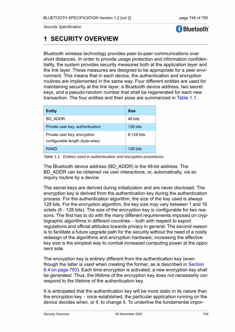
BLUETOOTH SPECIFICATION Version 1.2 [vol 2] page 749 of 790
Security Specification
1 SECURITY OVERVIEW
Bluetooth wireless technology provides peer-to-peer communications over short distances. In order to provide usage protection and information confiden-tiality, the system provides security measures both at the application layer and the link layer. These measures are designed to be appropriate for a peer envi-ronment. This means that in each device, the authentication and encryption routines are implemented in the same way. Four different entities are used for maintaining security at the link layer: a Bluetooth device address, two secret keys, and a pseudo-random number that shall be regenerated for each new transaction. The four entities and their sizes are summarized in Table 1.1.
The Bluetooth device address (BD_ADDR) is the 48-bit address. The BD_ADDR can be obtained via user interactions, or, automatically, via an inquiry routine by a device.
The secret keys are derived during initialization and are never disclosed. The encryption key is derived from the authentication key during the authentication process. For the authentication algorithm, the size of the key used is always 128 bits. For the encryption algorithm, the key size may vary between 1 and 16 octets (8 - 128 bits). The size of the encryption key is configurable for two rea-sons. The first has to do with the many different requirements imposed on cryp-tographic algorithms in different countries − both with respect to export regulations and official attitudes towards privacy in general. The second reason is to facilitate a future upgrade path for the security without the need of a costly redesign of the algorithms and encryption hardware; increasing the effective key size is the simplest way to combat increased computing power at the oppo-nent side.
The encryption key is entirely different from the authentication key (even though the latter is used when creating the former, as is described in Section 6.4 on page 783). Each time encryption is activated, a new encryption key shall be generated. Thus, the lifetime of the encryption key does not necessarily cor-respond to the lifetime of the authentication key.
It is anticipated that the authentication key will be more static in its nature than the encryption key − once established, the particular application running on the device decides when, or if, to change it. To underline the fundamental impor-
Entity Size
BD_ADDR 48 bits
Private user key, authentication 128 bits
Private user key, encryptionconfigurable length (byte-wise)
8-128 bits
RAND 128 bits
Table 1.1: Entities used in authentication and encryption procedures.
Security Overview 05 November 2003 749

BLUETOOTH SPECIFICATION Version 1.2 [vol 2] page 750 of 790
Security Specification
tance of the authentication key to a specific link, it is often be referred to as the link key.
The RAND is a pseudo-random number which can be derived from a random or pseudo-random process in the device. This is not a static parameter, it will change frequently.
In the remainder of this chapter, the terms user and application will be used interchangeably to designate the entity that is at either side.
750 05 November 2003 Security Overview
BLUETOOTH SPECIFICATION Version 1.2 [vol 2] page 751 of 790
Security Specification
2 RANDOM NUMBER GENERATION
Each device has a pseudo-random number generator. Pseudo-random num-bers are used for many purposes within the security functions − for instance, for the challenge-response scheme, for generating authentication and encryp-tion keys, etc. Ideally, a true random generator based on some physical pro-cess with inherent randomness should be used as a seed. Examples of such processes are thermal noise from a semiconductor or resistor and the fre-quency instability of a free running oscillator. For practical reasons, a software based solution with a pseudo-random generator is probably preferable. In gen-eral, it is quite difficult to classify the randomness of a pseudo-random sequence. Within this specification, the requirements placed on the random numbers used are non-repeating and randomly generated.
The expression ‘non-repeating’ means that it shall be highly unlikely that the value will repeat itself within the lifetime of the authentication key. For example, a non-repeating value could be the output of a counter that is unlikely to repeat during the lifetime of the authentication key, or a date/time stamp.
The expression ‘randomly generated’ means that it shall not be possible to pre-dict its value with a chance that is significantly larger than 0 (e.g., greater than
for a key length of L bits).
The LM may use such a generator for various purposes; i.e. whenever a ran-dom number is needed (such as the RANDs, the unit keys, Kinit, Kmaster, and random back-off or waiting intervals).
1 2L⁄
Random Number Generation 05 November 2003 751

BLUETOOTH SPECIFICATION Version 1.2 [vol 2] page 752 of 790
Security Specification
752 05 November 2003 Random Number Generation

BLUETOOTH SPECIFICATION Version 1.2 [vol 2] page 753 of 790
Security Specification
3 KEY MANAGEMENT
It is important that the encryption key size within a specific device cannot be set by the user − this should be a factory preset entity. In order to prevent the user from over-riding the permitted key size, the Bluetooth baseband processing shall not accept an encryption key given from higher software layers. When-ever a new encryption key is required, it shall be created as defined in Section 6.4 on page 783.
Changing a link key shall also be done through the defined baseband proce-dures. Depending on what kind of link key it is, different approaches are required. The details are found in Section 3.2.7 on page 760.
3.1 KEY TYPES
The link key is a 128-bit random number which is shared between two or more parties and is the base for all security transactions between these parties. The link key itself is used in the authentication routine. Moreover, the link key is used as one of the parameters when the encryption key is derived.
In the following, a session is defined as the time interval for which the device is a member of a particular piconet. Thus, the session terminates when the device disconnects from the piconet.
The link keys are either semi-permanent or temporary. A semi-permanent link key may be stored in non-volatile memory and may be used after the current session is terminated. Consequently, once a semi-permanent link key is defined, it may be used in the authentication of several subsequent connec-tions between the devices sharing it. The designation semi-permanent is justi-fied by the possibility of changing it. How to do this is described in Section 3.2.7 on page 760.
The lifetime of a temporary link key is limited by the lifetime of the current ses-sion − it shall not be reused in a later session. Typically, in a point-to-multipoint configuration where the same information is to be distributed securely to sev-eral recipients, a common encryption key is useful. To achieve this, a special link key (denoted master key) may temporarily replace the current link keys. The details of this procedure are found in Section 3.2.6 on page 759.
In the following, the current link key is the link key in use at the current moment. It can be semi-permanent or temporary. Thus, the current link key is used for all authentications and all generation of encryption keys in the on-going connec-tion (session).
Key Management 05 November 2003 753
BLUETOOTH SPECIFICATION Version 1.2 [vol 2] page 754 of 790
Security Specification
In order to accommodate different types of applications, four types of link keys have been defined:
• the combination key KAB
• the unit key KA
• the temporary key Kmaster
• the initialization key Kinit
Note: the use of unit keys is deprecated since it is implicitly insecure.
In addition to these keys there is an encryption key, denoted Kc. This key is derived from the current link key. Whenever encryption is activated by an LM command, the encryption key shall be changed automatically. The purpose of separating the authentication key and encryption key is to facilitate the use of a shorter encryption key without weakening the strength of the authentication procedure. There are no governmental restrictions on the strength of authenti-cation algorithms. However, in some countries, such restrictions exist on the strength of encryption algorithms.
The combination key KAB and the unit key KA are functionally indistinguishable; the difference is in the way they are generated. The unit key KA is generated in, and therefore dependent on, a single device A. The unit key shall be generated once at installation of the device; thereafter, it is very rarely changed. The com-bination key is derived from information in both devices A and B, and is there-fore always dependent on two devices. The combination key is derived for each new combination of two devices.
It depends on the application or the device whether a unit key or a combination key is used. Devices which have little memory to store keys, or are installed in equipment that will be accessible to a large group of users, should use their own unit key. In that case, they only have to store a single key. Applications that require a higher security level should use the combination keys. These applications will require more memory since a combination key for each link to a different device has to be stored.
The master key, Kmaster, shall only be used during the current session. It shall only replace the original link key temporarily. For example, this may be utilized when a master wants to reach more than two devices simultaneously using the same encryption key, see Section 3.2.6 on page 759.
The initialization key, Kinit, shall be used as the link key during the initialization process when no combination or unit keys have been defined and exchanged yet or when a link key has been lost. The initialization key protects the transfer of initialization parameters. The key is derived from a random number, an L-octet PIN code, and a BD_ADDR. This key shall only be used during initialization.
754 05 November 2003 Key Management
BLUETOOTH SPECIFICATION Version 1.2 [vol 2] page 755 of 790
Security Specification
The PIN may be a fixed number provided with the device (for example when there is no user interface as in a PSTN plug). Alternatively, the PIN can be selected by the user, and then entered in both devices that are to be matched. The latter procedure should be used when both devices have a user interface, for example a phone and a laptop. Entering a PIN in both devices is more secure than using a fixed PIN in one of the devices, and should be used when-ever possible. Even if a fixed PIN is used, it shall be possible to change the PIN; this is in order to prevent re-initialization by users who once got hold of the PIN. If no PIN is available, a default value of zero may be used. The length of this default PIN is one byte, PIN(default) = 0x00. This default PIN may be pro-vided by the host.
For many applications the PIN code will be a relatively short string of numbers. Typically, it may consist of only four decimal digits. Even though this gives suffi-cient security in many cases, there exist countless other, more sensitive, situa-tions where this is not reliable enough. Therefore, the PIN code may be chosen to be any length from 1 to 16 octets. For the longer lengths, the devices exchanging PIN codes may not use mechanical (i.e. human) interaction, but rather may use software at the application layer. For example, this can be a Dif-fie-Hellman key agreement, where the exchanged key is passed on to the generation process in both devices, just as in the case of a shorter PIN code.
3.2 KEY GENERATION AND INITIALIZATIONThe link keys must be generated and distributed among the devices in order to be used in the authentication procedure. Since the link keys shall be secret, they shall not be obtainable through an inquiry routine in the same way as the Bluetooth device addresses. The exchange of the keys takes place during an initialization phase which shall be carried out separately for each two devices that are using authentication and encryption. The initialization procedures con-sist of the following five parts:• generation of an initialization key
• generation of link key
• link key exchange
• authentication
• generation of encryption key in each device (optional)
After the initialization procedure, the devices can proceed to communicate, or the link can be disconnected. If encryption is implemented, the E0 algorithm shall be used with the proper encryption key derived from the current link key. For any new connection established between devices A and B, they should use the common link key for authentication, instead of once more deriving Kinit from the PIN. A new encryption key derived from that particular link key shall be cre-ated next time encryption is activated.
If no link key is available, the LM shall automatically start an initialization proce-dure.
Kinit
Key Management 05 November 2003 755

BLUETOOTH SPECIFICATION Version 1.2 [vol 2] page 756 of 790
Security Specification
3.2.1 Generation of initialization key,
A link key is used temporarily during initialization, the initialization key . This key shall be derived by the algorithm from a BD_ADDR, a PIN code, the length of the PIN (in octets), and a random number IN_RAND. The princi-ple is depicted in Figure 6.4 on page 783. The 128-bit output from shall be used for key exchange during the generation of a link key. When the devices have performed the link key exchange, the initialization key shall be discarded.
When the initialization key is generated, the PIN is augmented with the BD_ADDR. If one device has a fixed PIN the BD_ADDR of the other device shall be used. If both devices have a variable PIN the BD_ADDR of the device that received IN_RAND shall be used. If both devices have a fixed PIN they cannot be paired. Since the maximum length of the PIN used in the algorithm cannot exceed 16 octets, it is possible that not all octets of BD_ADDR will be used. This procedure ensures that depends on the identity of the device with a variable PIN. A fraudulent device may try to test a large number of PINs by claiming another BD_ADDR each time. It is the application’s responsibility to take countermeasures against this threat. If the device address is kept fixed, the waiting interval before the next try may be increased exponentially (see Section 5.1 on page 775).
The details of the algorithm can be found in Section 6.3 on page 781.
3.2.2 Authentication
The authentication procedure shall be carried out as described in Section 5 on page 773. During each authentication, a new AU_RANDA shall be issued.
Mutual authentication is achieved by first performing the authentication proce-dure in one direction and then immediately performing the authentication pro-cedure in the opposite direction.
As a side effect of a successful authentication procedure an auxiliary parame-ter, the Authenticated Ciphering Offset (ACO), will be computed. The ACO shall be used for ciphering key generation as described in Section 3.2.5 on page 758.
The claimant/verifier status is determined by the LM.
3.2.3 Generation of a unit key
A unit key shall be generated when the device is in operation for the first time; i.e. not during each initialization. The unit key shall be generated by the algo-rithm as described in Section 6.3 on page 781. Once created, the unit key should be stored in non-volatile memory and very rarely changed. If after initialization
Kinit
Kinit
E22
E22
Kinit
E22
KA
E21
756 05 November 2003 Key Management

BLUETOOTH SPECIFICATION Version 1.2 [vol 2] page 757 of 790
Security Specification
the unit key is changed, any previously initialized devices will possess a wrong link key. At initialization, the application must determine which of the two parties will provide the unit key as the link key. Typically, this will be the device with restricted memory capabilities, since this device only has to remember its own unit key. The unit key shall be transferred to the other party and then stored as the link key for that particular party. So, for example in Figure 3.1 on page 757, the unit key of device A, , is being used as the link key for the connection A-B; device A sends the unit key to device B; device B will store as the link key
. For another initialization, for example with device C, device A will reuse its unit key , whereas device C stores it as .
Figure 3.1: Generation of unit key. When the unit key has been exchanged, the initialization key is discarded in both devices.
3.2.4 Generation of a combination key
To use a combination key, it is first generated during the initialization proce-dure. The combination key is the combination of two numbers generated in device A and B, respectively. First, each device shall generate a random num-ber, LK_RANDA and LK_RANDB. Then, utilizing with the random number and their own BD_ADDRs, the two random numbers
(EQ 1)
and
(EQ 2)
shall be created in device A and device B, respectively. These numbers consti-tute the devices’ contribution to the combination key that is to be created. Then, the two random numbers LK_RANDA and LK_RANDB shall be exchanged securely by XORing with the current link key, . Thus, device A shall send to device B, while device B shall send
to device A. If this is done during the initialization phase the link key .
KA
KA KA
KBA
KA KCA
KA
UNIT BUNIT A
Kinit
K K = BA A
initK
E21
LK_KA E21 LK_RANDA BD_ADDRA,( ),=
LK_KB E21 LK_RANDB BD_ADDRB,( ),=
KK LK_RANDA⊕
K LK_RANDB⊕
K Kinit=
Key Management 05 November 2003 757

BLUETOOTH SPECIFICATION Version 1.2 [vol 2] page 758 of 790
Security Specification
When the random numbers and have been mutually exchanged, each device shall recalculate the other device’s contribution to the combination key. This is possible since each device knows the Bluetooth device address of the other device. Thus, device A shall calculate (EQ 2) on page 757 and device B shall calculate (EQ 1) on page 757. After this, both devices shall combine the two numbers to generate the 128-bit link key. The combining operation is a simple bitwise modulo-2 addition (i.e. XOR). The result shall be stored in device A as the link key and in device B as the link key . When both devices have derived the new combination key, a mutual authentication procedure shall be initiated to confirm the success of the trans-action. The old link key shall be discarded after a successful exchange of a new combination key. The message flow between master and slave and the principle for creating the combination key is depicted in Figure 3.2 on page 758.
Figure 3.2: Generating a combination key. The old link key (K) is discarded after the exchange of a new combination key has succeeded
3.2.5 Generating the encryption key
The encryption key, , is derived by algorithm from the current link key, a 96-bit Ciphering OFfset number (COF), and a 128-bit random number. The COF is determined in one of two ways. If the current link key is a master key, then COF shall be derived from the master BD_ADDR. Otherwise the value of COF shall be set to the value of ACO as computed during the authentication procedure. Therefore:1
1. denotes the concatenation of and .
LK_RANDA LK_RANDB
KAB
KBA
Unit B
LK_KA E21 LK_RANDA BD_ADDRA,( )=
CA
CA LK_RANDA K⊕=
Authentication
LK_KB E21 LK_RANDB BD_ADDRB,( )=
LK_KB E21 LK_RANDB BD_ADDRB,( )=
LK_RANDA CA K⊕=
CB LK_RANDB K⊕=
CB
LK_RANDB CB K⊕=
LK_KA E21 LK_RANDA BD_ADDRA,( )=
KAB LK_KA LK_KB⊕= KBA LK_KA LK_KB⊕ KAB= =
Unit A
KC E3
x y∪ x y
758 05 November 2003 Key Management

BLUETOOTH SPECIFICATION Version 1.2 [vol 2] page 759 of 790
Security Specification
(EQ 3)
There is an explicit call of when the LM activates encryption. Consequently, the encryption key is automatically changed each time the device enters encryption mode. The details of the key generating function can be found in Section 6.4 on page 783.
3.2.6 Point-to-multipoint configuration
It is possible for the master to use separate encryption keys for each slave in a point-to-multipoint configuration with ciphering activated. Then, if the applica-tion requires more than one slave to listen to the same payload, each slave must be addressed individually. This can cause unwanted capacity loss for the piconet. Moreover, a slave might not be capable of switching between two or more encryption keys in real time (e.g., after looking at the LT_ADDR in the header). Thus, the master cannot use different encryption keys for broadcast messages and individually addressed traffic. Therefore, the master may tell several slave devices to use a common link key (and, hence, indirectly also to use a common encryption key) and may then broadcast the information encrypted. For many applications, this key is only of temporary interest. In the following discussion, this key is denoted by .
The transfer of necessary parameters shall be protected by the routine described in Section 3.2.8 on page 760. After the confirmation of successful reception in each slave, the master shall issue a command to the slaves to replace their respective current link key by the new (temporary) master key. Before encryption can be activated, the master shall also generate and distrib-ute a common EN_RAND to all participating slaves. Using this random number and the newly derived master key, each slave shall generate a new encryption key.
Note that the master must negotiate the encryption key length to use individu-ally with each slave that will use the master key. If the master has already negotiated with some of these slaves, it has knowledge of the sizes that can be accepted. There may be situations where the permitted key lengths of some devices are incompatible. In that case, the master must exclude the limiting device from the group.
When all slaves have received the necessary data, the master can communi-cate information on the piconet securely using the encryption key derived from the new temporary link key. Each slave in possession of the master key can eavesdrop on all encrypted traffic, not only the traffic intended for itself. The master may tell all participants to fall back to their old link keys simultaneously.
COF BD_ADDR BD_ADDR,∪ if link key is a master key ACO, otherwise.⎩
⎨⎧
=
E3
E3
Kmaster
Key Management 05 November 2003 759
BLUETOOTH SPECIFICATION Version 1.2 [vol 2] page 760 of 790
Security Specification
3.2.7 Modifying the link keys
A link key based on a unit key can be changed. The unit key is created once during first use. Typically, the link key should be changed rather than the unit key, as several devices may share the same unit key as link key (e.g. a printer whose unit key is distributed to all users using the printer’s unit key as link key). Changing the unit key will require re-initialization of all devices connecting. Changing the unit key can be justified in some circumstances, e.g. to deny access to all previously allowed devices.
If the key change concerns combination keys, then the procedure is straightfor-ward. The change procedure is identical to the procedure described in Figure 3.2 on page 758, using the current value of the combination key as link key. This procedure can be carried out at any time after the authentication and encryption start. Since the combination key corresponds to a single link, it can be modified each time this link is established. This will improve the security of the system since then old keys lose their validity after each session.
Starting up an entirely new initialization procedure is also possible. In that case, user interaction is necessary since a PIN will be required in the authentication and encryption procedures.
3.2.8 Generating a master key
The key-change routines described so far are semi-permanent. To create the master link key, which can replace the current link key during a session (see Section 3.2.6 on page 759), other means are needed. First, the master shall create a new link key from two 128-bit random numbers, RAND1 and RAND2. This shall be done by
(EQ 4)
This key is a 128-bit random number. The reason for using the output of and not directly choosing a random number as the key, is to avoid possible problems with degraded randomness due to a poor implementation of the ran-dom number generator within the device.
Then, a third random number, RAND, shall be transmitted to the slave. Using with the current link key and RAND as inputs, both the master and the
slave shall compute a 128-bit overlay. The master shall send the bitwise XOR of the overlay and the new link key to the slave. The slave, who knows the overlay, shall recalculate . To confirm the success of this transaction, the devices shall perform a mutual authentication procedure using the new link key. This procedure shall then be repeated for each slave that receives the new link key. The ACO values from the authentications shall not replace the current ACO, as this ACO is needed to (re)compute a ciphering key when the master falls back to the previous (non-temporary) link key.
Kmaster E22 RAND1 RAND2 16, ,( ).=
E22
E22
Kmaster
760 05 November 2003 Key Management
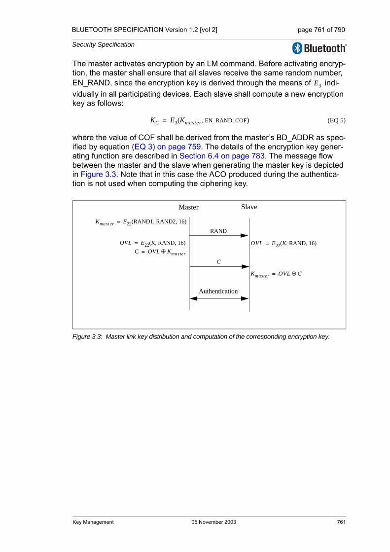
BLUETOOTH SPECIFICATION Version 1.2 [vol 2] page 761 of 790
Security Specification
The master activates encryption by an LM command. Before activating encryp-tion, the master shall ensure that all slaves receive the same random number, EN_RAND, since the encryption key is derived through the means of indi-vidually in all participating devices. Each slave shall compute a new encryption key as follows:
(EQ 5)
where the value of COF shall be derived from the master’s BD_ADDR as spec-ified by equation (EQ 3) on page 759. The details of the encryption key gener-ating function are described in Section 6.4 on page 783. The message flow between the master and the slave when generating the master key is depicted in Figure 3.3. Note that in this case the ACO produced during the authentica-tion is not used when computing the ciphering key.
Figure 3.3: Master link key distribution and computation of the corresponding encryption key.
E3
KC E3 Kmaster EN_RAND, COF,( )=
Master Slave
RANDKmaster E22 RAND1 RAND2, 16,( )=
OVL E22 K RAND, 16,( )= OVL E22 K RAND, 16,( )=C OVL Kmaster⊕=
Kmaster OVL C⊕=
C
Authentication
Key Management 05 November 2003 761

BLUETOOTH SPECIFICATION Version 1.2 [vol 2] page 762 of 790
Security Specification
762 05 November 2003 Key Management
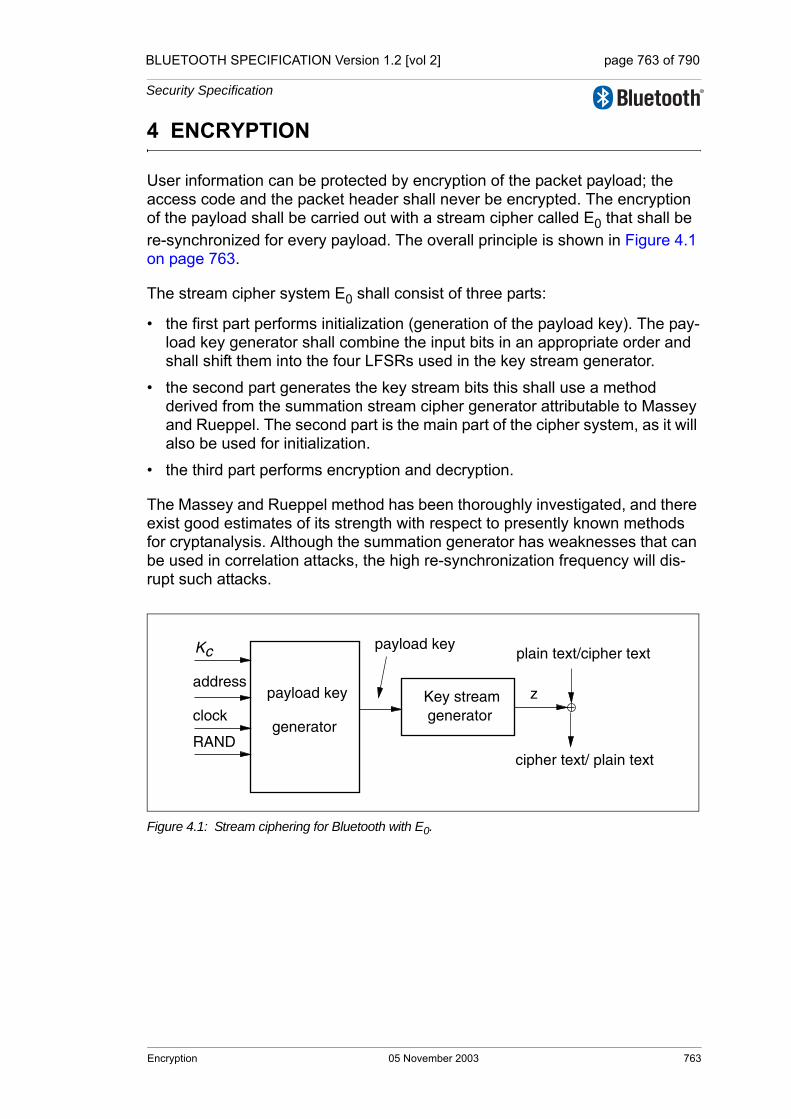
BLUETOOTH SPECIFICATION Version 1.2 [vol 2] page 763 of 790
Security Specification
4 ENCRYPTION
User information can be protected by encryption of the packet payload; the access code and the packet header shall never be encrypted. The encryption of the payload shall be carried out with a stream cipher called E0 that shall be re-synchronized for every payload. The overall principle is shown in Figure 4.1 on page 763.
The stream cipher system E0 shall consist of three parts:
• the first part performs initialization (generation of the payload key). The pay-load key generator shall combine the input bits in an appropriate order and shall shift them into the four LFSRs used in the key stream generator.
• the second part generates the key stream bits this shall use a method derived from the summation stream cipher generator attributable to Massey and Rueppel. The second part is the main part of the cipher system, as it will also be used for initialization.
• the third part performs encryption and decryption.
The Massey and Rueppel method has been thoroughly investigated, and there exist good estimates of its strength with respect to presently known methods for cryptanalysis. Although the summation generator has weaknesses that can be used in correlation attacks, the high re-synchronization frequency will dis-rupt such attacks.
Figure 4.1: Stream ciphering for Bluetooth with E0.
generatorKey stream z
plain text/cipher text
cipher text/ plain text
address
generator
payload key
payload key
clock
Kc
RAND
Encryption 05 November 2003 763
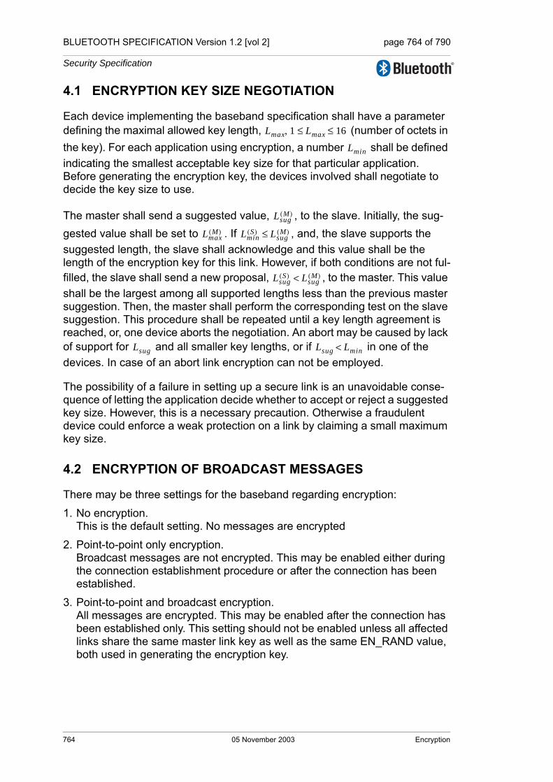
BLUETOOTH SPECIFICATION Version 1.2 [vol 2] page 764 of 790
Security Specification
4.1 ENCRYPTION KEY SIZE NEGOTIATION
Each device implementing the baseband specification shall have a parameter defining the maximal allowed key length, (number of octets in the key). For each application using encryption, a number shall be defined indicating the smallest acceptable key size for that particular application. Before generating the encryption key, the devices involved shall negotiate to decide the key size to use.
The master shall send a suggested value, , to the slave. Initially, the sug-gested value shall be set to . If , and, the slave supports the suggested length, the slave shall acknowledge and this value shall be the length of the encryption key for this link. However, if both conditions are not ful-filled, the slave shall send a new proposal, , to the master. This value shall be the largest among all supported lengths less than the previous master suggestion. Then, the master shall perform the corresponding test on the slave suggestion. This procedure shall be repeated until a key length agreement is reached, or, one device aborts the negotiation. An abort may be caused by lack of support for and all smaller key lengths, or if in one of the devices. In case of an abort link encryption can not be employed.
The possibility of a failure in setting up a secure link is an unavoidable conse-quence of letting the application decide whether to accept or reject a suggested key size. However, this is a necessary precaution. Otherwise a fraudulent device could enforce a weak protection on a link by claiming a small maximum key size.
4.2 ENCRYPTION OF BROADCAST MESSAGES
There may be three settings for the baseband regarding encryption:
1. No encryption. This is the default setting. No messages are encrypted
2. Point-to-point only encryption. Broadcast messages are not encrypted. This may be enabled either during the connection establishment procedure or after the connection has been established.
3. Point-to-point and broadcast encryption. All messages are encrypted. This may be enabled after the connection has been established only. This setting should not be enabled unless all affected links share the same master link key as well as the same EN_RAND value, both used in generating the encryption key.
Lmax 1 Lmax 16≤ ≤,
Lmin
LsugM( )
LmaxM( ) Lmin
S( ) LsugM( )≤
LsugS( ) Lsug
M( )<
Lsug Lsug Lmin<
764 05 November 2003 Encryption

BLUETOOTH SPECIFICATION Version 1.2 [vol 2] page 765 of 790
Security Specification
4.3 ENCRYPTION CONCEPT
For the encryption routine, a stream cipher algorithm is used in which ciphering bits are bit-wise modulo-2 added to the data stream to be sent over the air interface. The payload is ciphered after the CRC bits are appended, but, prior to the FEC encoding.
Each packet payload shall be ciphered separately. The cipher algorithm uses the master Bluetooth device address (BD_ADDR), 26 bits of the master real-time clock (CLK 26-1) and the encryption key as input, see Figure 4.2 on page 766 (where it is assumed that device A is the master).
The encryption key KC is derived from the current link key, COF, and a random number, EN_RANDA (see Section 6.4 on page 783). The random number shall be issued by the master before entering encryption mode. Note that EN_RANDA is publicly known since it is transmitted as plain text over the air.
Within the algorithm, the encryption key is modified into another key denoted . The maximum effective size of this key shall be factory preset and may be set to any multiple of eight between one and sixteen (8-128 bits). The procedure for deriving the key is described in Section 4.5 on page 769.
The real-time clock is incremented for each slot. The algorithm shall be re-initialized at the start of each new packet (i.e. for Master-to-Slave as well as for Slave-to-Master transmission). By using CLK26-1 at least one bit is changed between two transmissions. Thus, a new keystream is generated after each re-initialization. For packets covering more than a single slot, the Bluetooth clock as found in the first slot shall be used for the entire packet.
The encryption algorithm generates a binary keystream, , which shall be modulo-2 added to the data to be encrypted. The cipher is symmetric; decryption shall be performed in exactly the same way using the same key as used for encryption.
Broadcast traffic Individually addressed traffic
No encryption No encryption
No encryption Encryption,
Encryption, Encryption,
Table 4.1: Possible encryption modes for a slave in possession of a master key.
Kmaster
Kmaster Kmaster
E0
KC
E0 KC
K′C
E0
E0 Kcipher
Encryption 05 November 2003 765

BLUETOOTH SPECIFICATION Version 1.2 [vol 2] page 766 of 790
Security Specification
Figure 4.2: Functional description of the encryption procedure
4.4 ENCRYPTION ALGORITHM
The system uses linear feedback shift registers (LFSRs) whose output is com-bined by a simple finite state machine (called the summation combiner) with 16 states. The output of this state machine is the key stream sequence, or, during initialization phase, the randomized initial start value. The algorithm uses an encryption key , a 48-bit Bluetooth address, the master clock bits CLK26-1, and a 128-bit RAND value. Figure 4.3 on page 767 shows the setup.
There are four LFSRs (LFSR1,...,LFSR4) of lengths , , , and, , with feedback polynomials as specified in Table 4.2 on page 767. The total length of the registers is 128. These polynomials are all primitive. The Hamming weight of all the feedback polynomials is chosen to be five − a rea-sonable trade-off between reducing the number of required XOR gates in the hardware implementation and obtaining good statistical properties of the gen-erated sequences.
dataB-A
dataA-B
Kcipher Kcipher
E0
E0
Device BDevice A (master)
data
clockA
Kc
BD_ADDRA
clockA
BD_ADDRA
EN_RANDA
Kc
KC
L1 25= L2 31= L3 33=
L4 39=
766 05 November 2003 Encryption

BLUETOOTH SPECIFICATION Version 1.2 [vol 2] page 767 of 790
Security Specification
Figure 4.3: Concept of the encryption engine.
Let denote the symbol of LFSRi. The value is derived from the four-tuple using the following equation:
(EQ 6)
where the sum is over the integers. Thus can take the values 0,1,2,3, or 4. The output of the summation generator is obtained by the following equations:
(EQ 7)
feedback weight
1 25 5
2 31 5
3 33 5
4 39 5
Table 4.2: The four primitive feedback polynomials.
LFSR1
LFSR2
LFSR3
LFSR4
initi
al v
alue
s x1t
x2t
x3t
x4t
c0t
Encryption Stream Zt
Summation Combiner Logic
+
XOR
+ /2
21
3
2
2
3 2
T1
T2
blend
z-1
z-1
ct
ct+1
st+1
yt
XOR
2
2
x1t
x2t
x3t
x4t
i Li fi t( )
t25 t20 t12 t8 1+ + + +
t31 t24 t16 t12 1+ + + +
t33 t28 t24 t4 1+ + + +
t39 t36 t28 t4 1+ + + +
xti tth yt
xt1 … xt
4, ,
yt xti
i 1=
4
∑= ,
yt
zt xt1 xt
2 xt3 xt
4 ct0⊕ ⊕ ⊕ ⊕ 0 1,{ },∈=
Encryption 05 November 2003 767

BLUETOOTH SPECIFICATION Version 1.2 [vol 2] page 768 of 790
Security Specification
(EQ 8)
(EQ 9)
where and are two different linear bijections over GF(4). Suppose GF(4) is generated by the irreducible polynomial , and let be a zero of this polynomial in GF(4). The mappings and are now defined as:
The elements of GF(4) can be written as binary vectors. This is summarized in Table 4.3.
Since the mappings are linear, they can be implemented using XOR gates; i.e.
4.4.1 The operation of the cipher
Figure 4.4 on page 768 gives an overview of the operation in time. The encryp-tion algorithm shall run through the initialization phase before the start of trans-mission or reception of a new packet. Thus, for multislot packets the cipher is initialized using the clock value of the first slot in the multislot sequence.
Figure 4.4: Overview of the operation of the encryption engine. Between each start of a packet (TX or RX), the LFSRs are re-initialized.
00 00 00
01 01 11
10 10 01
11 11 10
Table 4.3: The mappings T1 and T2.
st 1+ st 1+1 st 1+
0,( ) yt ct+
2-------------- 0 1 2 3, , ,{ },∈= =
ct 1+ ct 1+1 ct 1+
0,( ) st 1+ T1 ct[ ] T2 ct 1–[ ],⊕ ⊕= =
T1 .[ ] T2 .[ ]
x2 x 1+ + αT1 T2
T1: GF 4( ) GF 4( )→
x x|→
T2: GF 4( ) GF 4( )→
x α 1+( )x.|→
x T1 x[ ] T2 x[ ]
T1: x1 x0,( ) x1 x0,( ),|→
T2: x1 x0,( ) x0 x1 x0⊕,( ).|→
768 05 November 2003 Encryption
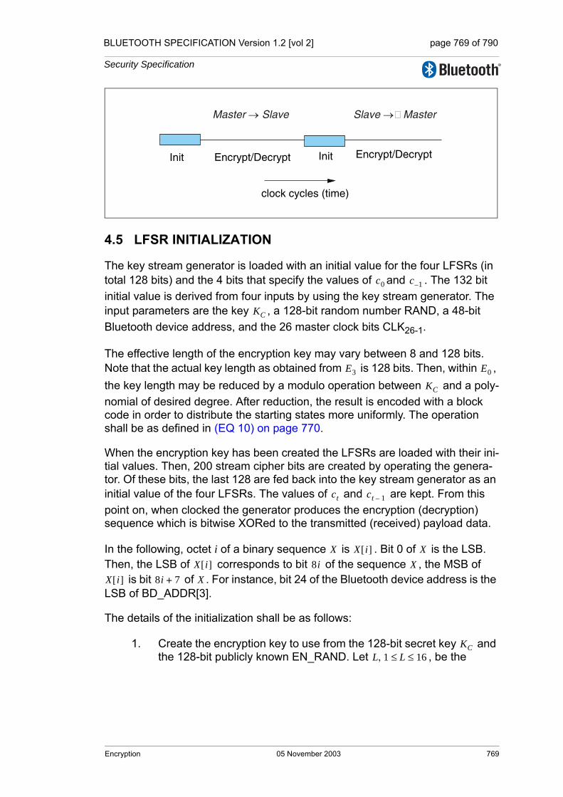
BLUETOOTH SPECIFICATION Version 1.2 [vol 2] page 769 of 790
Security Specification
4.5 LFSR INITIALIZATION
The key stream generator is loaded with an initial value for the four LFSRs (in total 128 bits) and the 4 bits that specify the values of and . The 132 bit initial value is derived from four inputs by using the key stream generator. The input parameters are the key , a 128-bit random number RAND, a 48-bit Bluetooth device address, and the 26 master clock bits CLK26-1.
The effective length of the encryption key may vary between 8 and 128 bits. Note that the actual key length as obtained from is 128 bits. Then, within , the key length may be reduced by a modulo operation between and a poly-nomial of desired degree. After reduction, the result is encoded with a block code in order to distribute the starting states more uniformly. The operation shall be as defined in (EQ 10) on page 770.
When the encryption key has been created the LFSRs are loaded with their ini-tial values. Then, 200 stream cipher bits are created by operating the genera-tor. Of these bits, the last 128 are fed back into the key stream generator as an initial value of the four LFSRs. The values of and are kept. From this point on, when clocked the generator produces the encryption (decryption) sequence which is bitwise XORed to the transmitted (received) payload data.
In the following, octet i of a binary sequence is . Bit 0 of is the LSB. Then, the LSB of corresponds to bit of the sequence , the MSB of
is bit of . For instance, bit 24 of the Bluetooth device address is the LSB of BD_ADDR[3].
The details of the initialization shall be as follows:
1. Create the encryption key to use from the 128-bit secret key and the 128-bit publicly known EN_RAND. Let , be the
clock cycles (time)
Init Encrypt/Decrypt Encrypt/DecryptInit
Master → Slave Slave → Master
c0 c 1–
KC
E3 E0
KC
ct ct 1–
X X i[ ] XX i[ ] 8i X
X i[ ] 8i 7+ X
KCL 1 L 16≤ ≤,
Encryption 05 November 2003 769
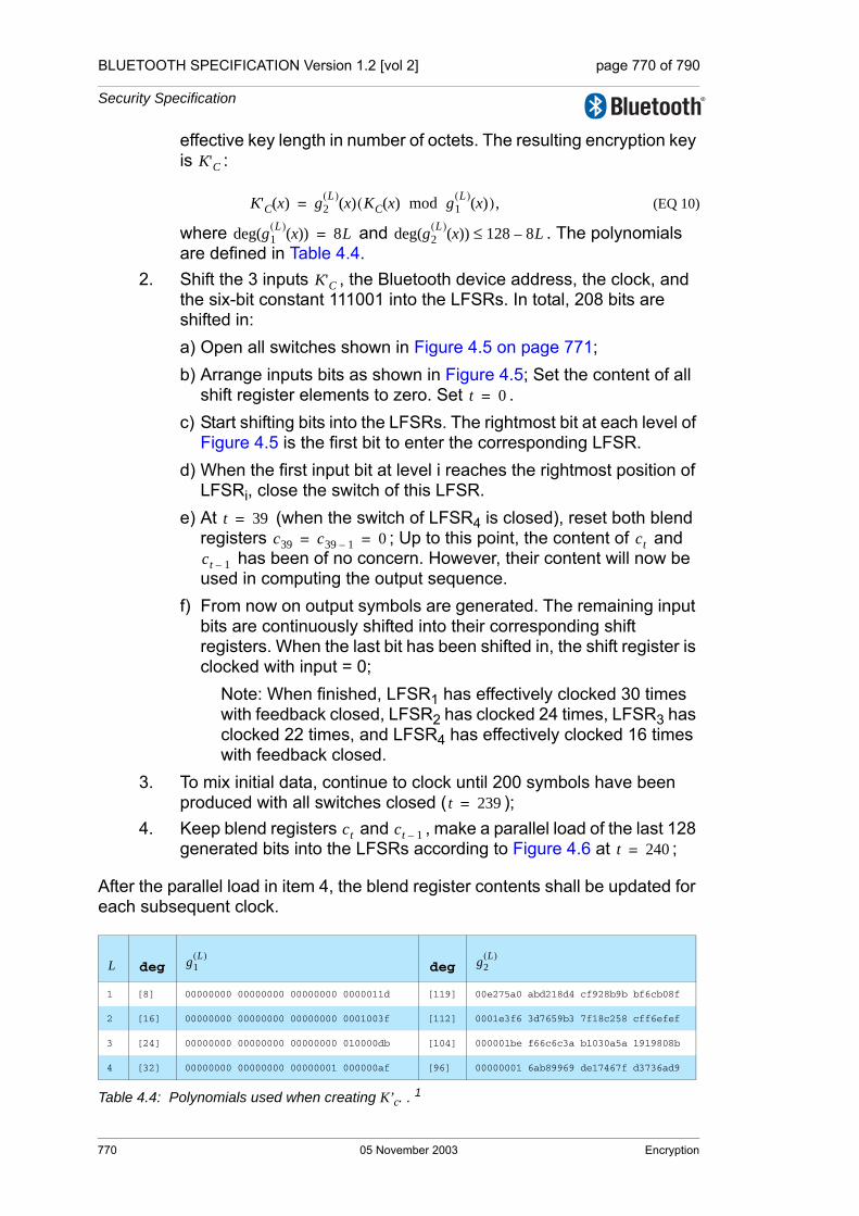
BLUETOOTH SPECIFICATION Version 1.2 [vol 2] page 770 of 790
Security Specification
effective key length in number of octets. The resulting encryption key is :
(EQ 10)
where and . The polynomials are defined in Table 4.4.
2. Shift the 3 inputs , the Bluetooth device address, the clock, and the six-bit constant 111001 into the LFSRs. In total, 208 bits are shifted in:a) Open all switches shown in Figure 4.5 on page 771;b) Arrange inputs bits as shown in Figure 4.5; Set the content of all
shift register elements to zero. Set . c) Start shifting bits into the LFSRs. The rightmost bit at each level of
Figure 4.5 is the first bit to enter the corresponding LFSR.d) When the first input bit at level i reaches the rightmost position of
LFSRi, close the switch of this LFSR.e) At (when the switch of LFSR4 is closed), reset both blend
registers ; Up to this point, the content of and has been of no concern. However, their content will now be
used in computing the output sequence.f) From now on output symbols are generated. The remaining input
bits are continuously shifted into their corresponding shift registers. When the last bit has been shifted in, the shift register is clocked with input = 0;
Note: When finished, LFSR1 has effectively clocked 30 times with feedback closed, LFSR2 has clocked 24 times, LFSR3 has clocked 22 times, and LFSR4 has effectively clocked 16 times with feedback closed.
3. To mix initial data, continue to clock until 200 symbols have been produced with all switches closed ( );
4. Keep blend registers and , make a parallel load of the last 128 generated bits into the LFSRs according to Figure 4.6 at ;
After the parallel load in item 4, the blend register contents shall be updated for each subsequent clock.
deg deg
1 [8] 00000000 00000000 00000000 0000011d [119] 00e275a0 abd218d4 cf928b9b bf6cb08f
2 [16] 00000000 00000000 00000000 0001003f [112] 0001e3f6 3d7659b3 7f18c258 cff6efef
3 [24] 00000000 00000000 00000000 010000db [104] 000001be f66c6c3a b1030a5a 1919808b
4 [32] 00000000 00000000 00000001 000000af [96] 00000001 6ab89969 de17467f d3736ad9
Table 4.4: Polynomials used when creating K’c. . 1
K'C
K'C x( ) g2L( ) x( ) KC x( ) mod g1
L( ) x( )( ),=
deg g1L( ) x( )( ) 8L= deg g2
L( ) x( )( ) 128 8L–≤
K'C
t 0=
t 39=c39 c39 1– 0= = ct
ct 1–
t 239=
ct ct 1–t 240=
L g1L( ) g2
L( )
770 05 November 2003 Encryption

BLUETOOTH SPECIFICATION Version 1.2 [vol 2] page 771 of 790
Security Specification
In Figure 4.5, all bits are shifted into the LFSRs, starting with the least signifi-cant bit (LSB). For instance, from the third octet of the address, BD_ADDR[2], first BD_ADDR16 is entered, followed by BD_ADDR17, etc. Furthermore, CL0 corresponds to CLK1,..., CL25 corresponds to CLK26.
Note that the output symbols are taken from the positions 24, 24, 32, and 32 for LFSR1, LFSR2,LFSR3, and LFSR4, respectively (counting the leftmost position as number 1).
Figure 4.5: Arranging the input to the LFSRs.
5 [40] 00000000 00000000 00000100 00000039 [88] 00000000 01630632 91da50ec 55715247
6 [48] 00000000 00000000 00010000 00000291 [77] 00000000 00002c93 52aa6cc0 54468311
7 [56] 00000000 00000000 01000000 00000095 [71] 00000000 000000b3 f7fffce2 79f3a073
8 [64] 00000000 00000001 00000000 0000001b [63] 00000000 00000000 a1ab815b c7ec8025
9 [72] 00000000 00000100 00000000 00000609 [49] 00000000 00000000 0002c980 11d8b04d
10 [80] 00000000 00010000 00000000 00000215 [42] 00000000 00000000 0000058e 24f9a4bb
11 [88] 00000000 01000000 00000000 0000013b [35] 00000000 00000000 0000000c a76024d7
12 [96] 00000001 00000000 00000000 000000dd [28] 00000000 00000000 00000000 1c9c26b9
13 [104] 00000100 00000000 00000000 0000049d [21] 00000000 00000000 00000000 0026d9e3
14 [112] 00010000 00000000 00000000 0000014f [14] 00000000 00000000 00000000 00004377
15 [120] 01000000 00000000 00000000 000000e7 [7] 00000000 00000000 00000000 00000089
16 [128] 1 00000000 00000000 00000000 00000000 [0] 00000000 00000000 00000000 00000001
1. All polynomials are in hexadecimal notation. The LSB is in the rightmost position.
deg deg
Table 4.4: Polynomials used when creating K’c. . 1
L g1L( ) g2
L( )
xti i, 1 … 4, ,=
= CLCL ...CL[0]
= CLCL ...CL[0]L
U
3 0
7 4
CL24
CL[0]L
CL25
UCL[0]
X 4
X
X
X 1
2
3
0 0 116 24
24
36
8 12 20
12
24
24
32
32
28
284
4
t
t
t
t
Kc'[0]Kc'[4]Kc'[8]Kc'[12]CL[1]ADR[2]
Kc'[1]Kc'[5]Kc'[9]Kc'[13]ADR[0]ADR[3]
Kc'[2]Kc'[6]Kc'[10]Kc'[14]CL[2]ADR[4]
Kc'[11] Kc'[7] Kc'[3] 1 1 1Kc'[15]ADR[1]ADR[5]
Encryption 05 November 2003 771

BLUETOOTH SPECIFICATION Version 1.2 [vol 2] page 772 of 790
Security Specification
In Figure 4.6, the 128 binary output symbols Z0,..., Z127 are arranged in octets denoted Z[0],..., Z[15]. The LSB of Z[0] corresponds to the first of these sym-bols, the MSB of Z[15] is the last output from the generator. These bits shall be loaded into the LFSRs according to the figure. It is a parallel load and no update of the blend registers is done. The first output symbol is generated at the same time. The octets shall be written into the registers with the LSB in the leftmost position (i.e. the opposite of before). For example, Z24 is loaded into position 1 of LFSR4.
Figure 4.6: Distribution of the 128 last generated output symbols within the LFSRs.
4.6 KEY STREAM SEQUENCE
When the initialization is finished, the output from the summation combiner is used for encryption/decryption. The first bit to use shall be the one produced at the parallel load, i.e. at . The circuit shall be run for the entire length of the current payload. Then, before the reverse direction is started, the entire ini-tialization process shall be repeated with updated values on the input parame-ters.
Sample data of the encryption output sequence can be found in [Part G] Sec-tion 1 on page 649. A necessary, but not sufficient, condition for all Bluetooth compliant implementations of encryption is to produce these encryption streams for identical initialization values.
Z[3]
Xt
4
Xt
Xt
Xt
1
2
3
Z[4] Z[8]
Z[5]
Z[13]
Z[9]
Z[14]
Z[10]
Z[11]
Z[0]
Z[12]7-1
Z[6]
Z[7] Z[15]7-1
Z[2]
Z[1]
Z[12]0
Z[15]0
24
24
32
32
24
20128
12 16
4
4
24
28 36
28
t 240=
772 05 November 2003 Encryption

BLUETOOTH SPECIFICATION Version 1.2 [vol 2] page 773 of 790
Security Specification
5 AUTHENTICATION
Authentication uses a challenge-response scheme in which a claimant’s knowl-edge of a secret key is checked through a 2-move protocol using symmetric secret keys. The latter implies that a correct claimant/verifier pair share the same secret key, for example K. In the challenge-response scheme the verifier challenges the claimant to authenticate a random input (the challenge), denoted by AU_RANDA, with an authentication code, denoted by , and return the result SRES to the verifier, see Figure 5.1 on page 773. This figure also shows that the input to E1 consists of the tuple AU_RANDA and the Blue-tooth device address (BD_ADDR) of the claimant. The use of this address pre-vents a simple reflection attack1. The secret K shared by devices A and B is the current link key.
Figure 5.1: Challenge-response for the Bluetooth.
The challenge-response scheme for symmetric keys is depicted in Figure 5.2 on page 774.
1. The reflection attack actually forms no threat because all service requests are dealt with on a FIFO bases. When preemption is introduced, this attack is potentially dangerous.
E1
E1 E1
AU_RANDA
BD_ADDRB
Link key
AU_RANDA
BD_ADDRB
SRES’
AU_RANDA
SRES
?=SRES
Verifier (Device A) Claimant (Device B)
Link key
SRES
ACO ACO
Authentication 05 November 2003 773

BLUETOOTH SPECIFICATION Version 1.2 [vol 2] page 774 of 790
Security Specification
Figure 5.2: Challenge-response for symmetric key systems.
The verifier is not required to be the master. The application indicates which device has to be authenticated. Some applications only require a one-way authentication. However, some peer-to-peer communications, should use a mutual authentication in which each device is subsequently the challenger (verifier) in two authentication procedures. The LM shall process authentication preferences from the application to determine in which direction(s) the authen-tication(s) takes place. For mutual authentication with the devices of Figure 5.1 on page 773, after device A has successfully authenticated device B, device B could authenticate device A by sending an AU_RANDB (different from the AU_RANDA that device A issued) to device A, and deriving the SRES and SRES’ from the new AU_RANDB, the address of device A, and the link key KAB.
If an authentication is successful the value of ACO as produced by shall be retained.
Verifier(User A)
Claimant(User B, with identity IDB)
RAND
SRESSRES E key IDB RAND, ,( )=
SRES' E key IDB RAND, ,( )=
Check: SRES' SRES=
E1
774 05 November 2003 Authentication
BLUETOOTH SPECIFICATION Version 1.2 [vol 2] page 775 of 790
Security Specification
5.1 REPEATED ATTEMPTS
When the authentication attempt fails, a waiting interval shall pass before the verifier will initiate a new authentication attempt to the same claimant, or before it will respond to an authentication attempt initiated by a device claiming the same identity as the failed device. For each subsequent authentication failure with the same Bluetooth device address, the waiting interval shall be increased exponentially. That is, after each failure, the waiting interval before a new attempt can be made, could be for example, twice as long as the waiting inter-val prior to the previous attempt1. The waiting interval shall be limited to a max-imum. The maximum waiting interval depends on the implementation. The waiting time shall exponentially decrease to a minimum when no new failed attempts are made during a certain time period. This procedure prevents an intruder from repeating the authentication procedure with a large number of dif-ferent keys.
To make the system less vulnerable to denial-of-service attacks, the devices should keep a list of individual waiting intervals for each device it has established contact with. The size of this list may be restricted to only contain the N devices with which the most recent contacts have been made. The number N may vary for different devices depending on available memory size and user environment.
1. Another appropriate value larger than 1 may be used.
Authentication 05 November 2003 775

BLUETOOTH SPECIFICATION Version 1.2 [vol 2] page 776 of 790
Security Specification
776 05 November 2003 Authentication
BLUETOOTH SPECIFICATION Version 1.2 [vol 2] page 777 of 790
Security Specification
6 THE AUTHENTICATION AND KEY-GENERATING FUNCTIONS
This section describes the algorithms used for authentication and key genera-tion.
6.1 THE AUTHENTICATION FUNCTION E1
The authentication function is a computationally secure authentication code. uses the encryption function SAFER+. The algorithm is an enhanced version of an existing 64-bit block cipher SAFER-SK128, and it is freely avail-able. In the following discussion, the block cipher will be denoted as the func-tion which maps using a 128-bit key, a 128-bit input to a 128-bit output, i.e.
(EQ 11)
The details of are given in the next section. The function is constructed using as follows
(EQ 12)
where , where is a keyed hash function defined as1,
(EQ 13)
and where
(EQ 14)
is an expansion of the octet word into a 128-bit word. The function is
evaluated twice for each evaluation of . The key for the second use of
(actually ) is offset from as follows2
1. The operator +16 denotes bytewise addition mod 256 of the 16 octets, and the operator ⊕16 denotes bytewise XORing of the 16 octets.
2. The constants are the largest primes below 257 for which 10 is a primitive root.
E1
E1
Ar
Ar: 0 1,{ }128 0 1,{ }128× 0 1,{ }128→
k x×( ) t.|→
Ar E1
Ar
E1: 0 1,{ }128 0 1,{ }128 0 1,{ }48×× 0 1,{ }32 0 1,{ }96×→
K RAND address, ,( ) SRES ACO,( ),|→
SRES Hash K RAND,address 6,,( ) 0 … 3, ,[ ]= Hash
Hash: 0 1,{ }128 0 1,{ }128 0 1,{ }8 L× 6 12,{ }××× 0 1,{ }128→
K I1 I2 L, , ,( ) A'r K[ ] E I2 L,( ) Ar K I1,( )⊕16 I1( )+16[ ],( ),|→
E: 0 1,{ }8 L× 6 12,{ }× 0 1,{ }8 16×→
X 0 … L, , 1–[ ] L,( ) X i(mod L)[ ] for i = 0...15( ),|→
L X Ar
E1 K Ar
A'r K
The Authentication And Key-Generating Functions 05 November 2003 777

BLUETOOTH SPECIFICATION Version 1.2 [vol 2] page 778 of 790
Security Specification
(EQ 15)
A data flowchart of the computation of is shown in Figure 6.1 on page 778. is also used to deliver the parameter ACO (Authenticated Ciphering Offset)
that is used in the generation of the ciphering key by , see equations (EQ 3) on page 759 and (EQ 23) on page 783. The value of ACO is formed by the octets 4 through 15 of the output of the hash function defined in (EQ 13) on page 777, i.e.
. (EQ 16)
Figure 6.1: Flow of data for the computation of .
K 0[ ] K 0[ ] 233+( )= mod 256, K 1[ ] K 1[ ] 229,⊕=
K 2[ ] K 2[ ] 223+( )= mod 256, K 3[ ] K 3[ ] 193,⊕=
K 4[ ] K 4[ ] 179+( )= mod 256, K 5[ ] K 5[ ] 167,⊕=
K 6[ ] K 6[ ] 149+( )= mod 256, K 7[ ] K 7[ ] 131,⊕=
K 8{ } K 8[ ] 233,⊕= K 9[ ] K 9[ ] 229+( )= mod 256,K 10[ ] K 10[ ] 223,⊕= K 11[ ] K 11[ ] 193+( )= mod 256,K 12[ ] K 12[ ] 179,⊕= K 13[ ] K 13[ ] 167+( )= mod 256,K 14[ ] K 14[ ] 149,⊕= K 15[ ] K 15[ ] 131+( )= mod 256.
E1
E1
E3
ACO Hash K RAND,address 6,,( ) 4 … 15, ,[ ]=
+16offset
RAND
E
32 96
SRES ACO
address
+16
xor
add
xor :16 8-bit xor-ings
add: 16 8-bit additions mod 256
Ar
A'r
K
K
48
128
L 6=
E1
778 05 November 2003 The Authentication And Key-Generating
BLUETOOTH SPECIFICATION Version 1.2 [vol 2] page 779 of 790
Security Specification
6.2 THE FUNCTIONS Ar AND A’r
The function is identical to SAFER+. It consists of a set of 8 layers, (each layer is called a round) and a parallel mechanism for generating the sub keys
, , which are the round keys to be used in each round. The function will produce a 128-bit result from a 128-bit random input string and a 128-bit key. Besides the function , a slightly modified version referred to as
is used in which the input of round 1 is added to the input of round 3. This is done to make the modified version non-invertible and prevents the use of (especially in ) as an encryption function. See Figure 6.2 on page 780 for details.
6.2.1 The round computations
The computations in each round are a composition of encryption with a round key, substitution, encryption with the next round key, and, finally, a Pseudo Hadamard Transform (PHT). The computations in a round shall be as shown in Figure 6.2 on page 780. The sub keys for round are denoted
, , . After the last round is applied identically to all previous odd numbered keys.
6.2.2 The substitution boxes “e” and “l”
In Figure 6.2 on page 780 two boxes are shown, marked “e” and “l”. These boxes implement the same substitutions as are used in SAFER+; i.e. they implement
Their role, as in the SAFER+ algorithm, is to introduce non-linearity.
Ar
Kp j[ ] p 1 2 … 17, , ,=
Ar
A′rA′r
E2x
r r, 1 2 … 8, , ,=
K2r 1– j[ ] K2r j[ ] j 0 1 … 15, , ,= K17 j[ ]
e l, : 0 … 255, ,{ } 0 … 255, ,{ },→
e : i 45i (mod 257)( ) (mod 256),|→
l : i j s.t. i|→ e j( ).=
The Authentication And Key-Generating Functions 05 November 2003 779

BLUETOOTH SPECIFICATION Version 1.2 [vol 2] page 780 of 790
Security Specification
Figure 6.2: One round in and . The permutation boxes show how input byte indices are mapped onto output byte indices. Thus, position 8 is mapped on position 0 (leftmost), position 11 is mapped on position 1, et cetera.
6.2.3 Key scheduling
In each round, 2 batches of 16 octet-wide keys are needed. These round keys are derived as specified by the key scheduling in SAFER+. Figure 6.3 on page 781 gives an overview of how the round keys are determined. The bias vectors B2, B3, ..., B17 shall be computed according to following equation:
(EQ 17)
e e e e e e e e
PHT PHT PHT PHT PHT PHT
PHT PHT
PHT
PHT PHT
PHT
PHT PHT PHT PHT
PHT PHT PHT PHT PHT PHT PHT PHT
addition mod 256
bitwise XOR
PHT(x,y)= (2x+y mod 256, x+y mod 256)
2rK [0..15]
2r
l l l l l l l l
Only for A’r in round 3
A input[0..15]
128
128
PERMUTE: 8 11 12 15 2 1 6 5 10 9 14 13 0 7 4 3
PERMUTE: 8 11 12 15 2 1 6 5 10 9 14 13 0 7 4 3
PERMUTE: 8 11 12 15 2 1 6 5 10 9 14 13 0 7 4 3
PHT PHT PHT PHT PHT PHT PHT PHT
128 K [0..15]17
128
Only after last round
2r-1K [0..15]
RO
UN
D r
, r=1
,2,..
.,8
60 1 2 3 4 5 7 8 9 10 11 12 13 14 15
2rK [15]K [0]
Ar A'r
Kp j[ ]
Bp i[ ] 45 4517p i 1+ + mod 257( ) mod 257( ) mod 256( ), for i 0 … 15., ,= =
780 05 November 2003 The Authentication And Key-Generating

BLUETOOTH SPECIFICATION Version 1.2 [vol 2] page 781 of 790
Security Specification
Figure 6.3: Key scheduling in .
6.3 E2-KEY GENERATION FUNCTION FOR AUTHENTICATION
The key used for authentication shall be derived through the procedure that is shown in Figure 6.4 on page 783. The figure shows two modes of operation for the algorithm. In the first mode, produces a 128-bit kink key, , using a 128-bit RAND value and a 48-bit address. This mode shall be utilized when creating unit keys and combination keys. In the second mode, produces a 128-bit link key, , using a 128-bit RAND value and an octet user PIN. The second mode shall be used to create the initialization key, and also when a master key is to be generated.
When the initialization key is generated, the PIN is augmented with the BD_ADDR, see Section 3.2.1 on page 756 for which address to use. The aug-mentation shall always start with the least significant octet of the address immediately following the most significant octet of the PIN. Since the maximum length of the PIN used in the algorithm cannot exceed 16 octets, it is possible that not all octets of BD_ADDR will be used.
1
16
K
16
160 1 14
0 1514
0 1 1514
0 1 1514
0 1 1514
+
+
+15
1
...
bit-by-bitmodulo two
1,2,3,...,15,16
2,3,4,...,16,0
Select Bytes
16,0,1,...,13,14
16
16
160,1,2,...,14,15
16
B
B
B
2
3
17
K
K
2
3
17
K
Rotate each octet left by 3 bit positions
Rotate each octet left by 3 bit positions
Rotate each octet left by 3 bit positions
128 bit Key grouped in 16 octets
sum octets
Select octets
Select octets
Select octets
Ar
E21 K
E22
K L
The Authentication And Key-Generating Functions 05 November 2003 781
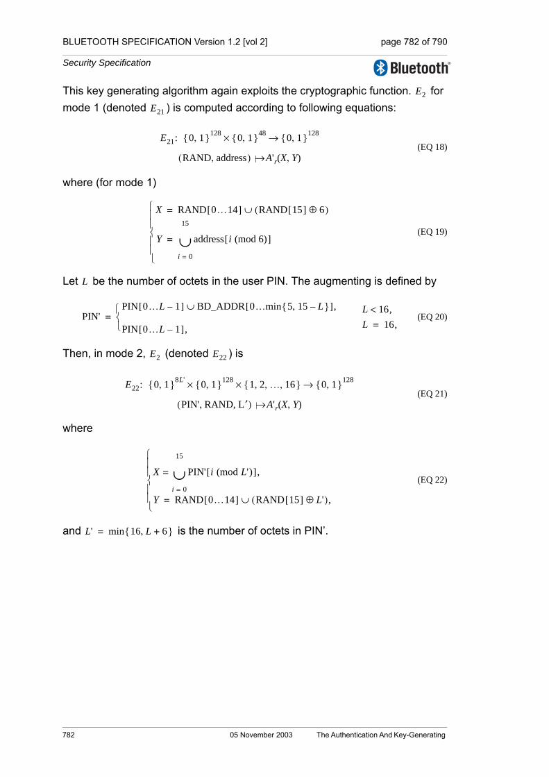
BLUETOOTH SPECIFICATION Version 1.2 [vol 2] page 782 of 790
Security Specification
This key generating algorithm again exploits the cryptographic function. for mode 1 (denoted ) is computed according to following equations:
(EQ 18)
where (for mode 1)
(EQ 19)
Let be the number of octets in the user PIN. The augmenting is defined by
(EQ 20)
Then, in mode 2, (denoted ) is
(EQ 21)
where
(EQ 22)
and is the number of octets in PIN’.
E2
E21
E21: 0 1,{ }128 0 1,{ }48× 0 1,{ }128→
RAND address,( ) A'r X Y,( )|→
X RAND 0…14[ ] RAND 15[ ] 6⊕( )∪=
Y address i (mod 6)[ ]
i 0=
15
∪=
⎩⎪⎪⎨⎪⎪⎧
L
PIN'PIN 0…L 1–[ ] BD_ADDR 0… 5 15 L–,{ }min[ ],∪
PIN 0…L 1–[ ],⎩⎨⎧
=L 16,<L 16,=
E2 E22
E22: 0 1,{ }8L' 0 1,{ }128 1 2 … 16, , ,{ }×× 0 1,{ }128→
PIN' RAND, L′,( ) A'r X Y,( )|→
X PIN' i (mod L')[ ]
i 0=
15
∪= ,
Y RAND 0…14[ ] RAND 15[ ] L'⊕( ),∪=⎩⎪⎪⎨⎪⎪⎧
L' min 16 L 6+,{ }=
782 05 November 2003 The Authentication And Key-Generating
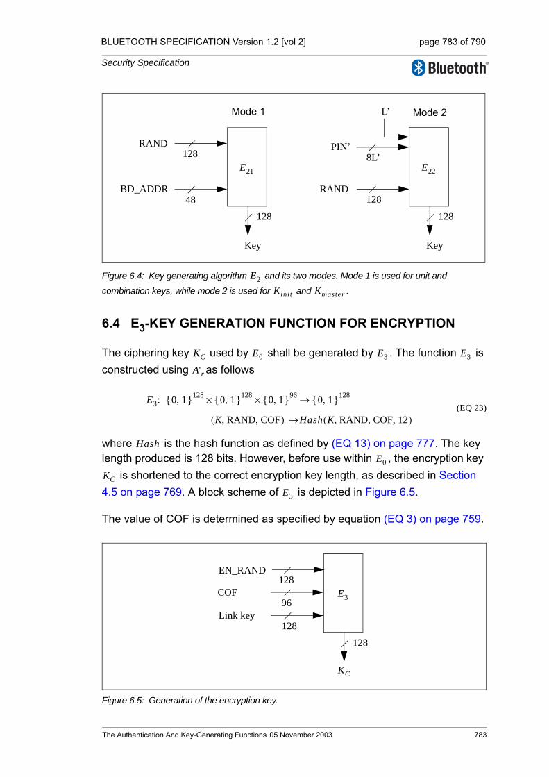
BLUETOOTH SPECIFICATION Version 1.2 [vol 2] page 783 of 790
Security Specification
Figure 6.4: Key generating algorithm and its two modes. Mode 1 is used for unit and combination keys, while mode 2 is used for and .
6.4 E3-KEY GENERATION FUNCTION FOR ENCRYPTION
The ciphering key used by shall be generated by . The function is constructed using as follows
(EQ 23)
where is the hash function as defined by (EQ 13) on page 777. The key length produced is 128 bits. However, before use within , the encryption key
is shortened to the correct encryption key length, as described in Section 4.5 on page 769. A block scheme of is depicted in Figure 6.5.
The value of COF is determined as specified by equation (EQ 3) on page 759.
Figure 6.5: Generation of the encryption key.
E22
RAND
PIN’
128
8L’
Key
128
E21
RAND
BD_ADDR
128
48
Key
128
Mode 1 Mode 2L’
E2
Kinit Kmaster
KC E0 E3 E3
A'r
E3: 0 1,{ }128 0 1,{ }128 0 1,{ }96×× 0 1,{ }128→
K RAND COF,,( ) Hash K RAND COF, 12, ,( )|→
HashE0
KC
E3
E3
EN_RAND128
128
128
96
KC
Link key
COF
The Authentication And Key-Generating Functions 05 November 2003 783

BLUETOOTH SPECIFICATION Version 1.2 [vol 2] page 784 of 790
Security Specification
784 05 November 2003 The Authentication And Key-Generating
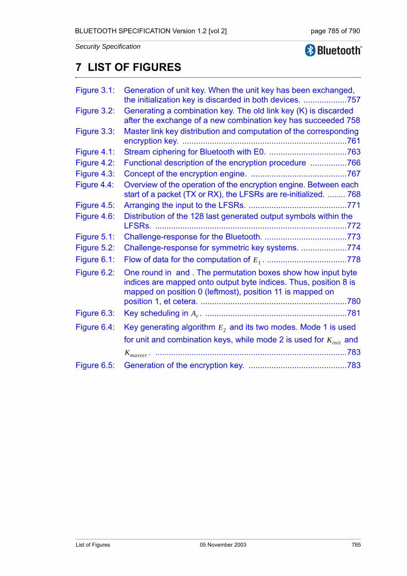
BLUETOOTH SPECIFICATION Version 1.2 [vol 2] page 785 of 790
Security Specification
7 LIST OF FIGURES
Figure 3.1: Generation of unit key. When the unit key has been exchanged, the initialization key is discarded in both devices. ...................757
Figure 3.2: Generating a combination key. The old link key (K) is discarded after the exchange of a new combination key has succeeded 758
Figure 3.3: Master link key distribution and computation of the corresponding encryption key. ........................................................................761
Figure 4.1: Stream ciphering for Bluetooth with E0. ..................................763Figure 4.2: Functional description of the encryption procedure ................766Figure 4.3: Concept of the encryption engine. ..........................................767Figure 4.4: Overview of the operation of the encryption engine. Between each
start of a packet (TX or RX), the LFSRs are re-initialized. ........ 768Figure 4.5: Arranging the input to the LFSRs. ...........................................771Figure 4.6: Distribution of the 128 last generated output symbols within the
LFSRs. ....................................................................................772Figure 5.1: Challenge-response for the Bluetooth. ....................................773Figure 5.2: Challenge-response for symmetric key systems. ....................774Figure 6.1: Flow of data for the computation of . ...................................778Figure 6.2: One round in and . The permutation boxes show how input byte
indices are mapped onto output byte indices. Thus, position 8 is mapped on position 0 (leftmost), position 11 is mapped on position 1, et cetera. ................................................................780
Figure 6.3: Key scheduling in . ..............................................................781
Figure 6.4: Key generating algorithm and its two modes. Mode 1 is used for unit and combination keys, while mode 2 is used for and
. ....................................................................................783Figure 6.5: Generation of the encryption key. ...........................................783
E1
Ar
E2
Kinit
Kmaster
List of Figures 05 November 2003 785

BLUETOOTH SPECIFICATION Version 1.2 [vol 2] page 786 of 790
Security Specification
786 05 November 2003 List of Figures
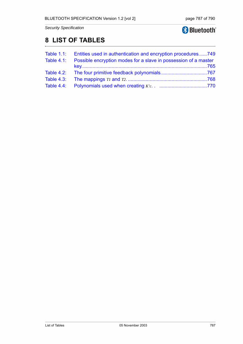
BLUETOOTH SPECIFICATION Version 1.2 [vol 2] page 787 of 790
Security Specification
8 LIST OF TABLES
Table 1.1: Entities used in authentication and encryption procedures......749Table 4.1: Possible encryption modes for a slave in possession of a master
key............................................................................................765Table 4.2: The four primitive feedback polynomials..................................767Table 4.3: The mappings T1 and T2. ..........................................................768Table 4.4: Polynomials used when creating K’c. . ...................................770
List of Tables 05 November 2003 787

BLUETOOTH SPECIFICATION Version 1.2 [vol 2] page 788 of 790
Security Specification
788 05 November 2003 List of Tables


790

1.2
Specificationof the Bluetooth System
Wireless connections made easy
Core SystemPackage[Host volume]
Version 1.2 05 November 2003
Specification Volume 3

BLUETOOTH SPECIFICATION Version 1.2 [vol 3] page 2 of 252
Revision History
The Revision History is shown in the “Appendix” on page 53[vol. 0].
Contributors
The persons who contributed to this specification are listed in the “Appendix” on page 53[vol. 0].
Web Site
This specification can also be found on the official Bluetooth website: http://www.bluetooth.com
Disclaimer and Copyright Notice
The copyright in these specifications is owned by the Promoter Members of Bluetooth SIG, Inc. (“Bluetooth SIG”). Use of these specifications and any related intellectual property (collectively, the “Specification”), is governed by the Promoters Membership Agreement among the Promoter Members and Blue-tooth SIG (the “Promoters Agreement”), certain membership agreements between Bluetooth SIG and its Adopter and Associate Members (the “Member-ship Agreements”) and the Bluetooth Specification Early Adopters Agreements (“1.2 Early Adopters Agreements”) among Early Adopter members of the unin-corporated Bluetooth special interest group and the Promoter Members (the “Early Adopters Agreement”). Certain rights and obligations of the Promoter Members under the Early Adopters Agreements have been assigned to Blue-tooth SIG by the Promoter Members.
Use of the Specification by anyone who is not a member of Bluetooth SIG or a party to an Early Adopters Agreement (each such person or party, a “Mem-ber”), is prohibited. The legal rights and obligations of each Member are gov-erned by their applicable Membership Agreement, Early Adopters Agreement or Promoters Agreement. No license, express or implied, by estoppel or other-wise, to any intellectual property rights are granted herein.
Any use of the Specification not in compliance with the terms of the applicable Membership Agreement, Early Adopters Agreement or Promoters Agreement is prohibited and any such prohibited use may result in termination of the appli-cable Membership Agreement or Early Adopters Agreement and other liability permitted by the applicable agreement or by applicable law to Bluetooth SIG or any of its members for patent, copyright and/or trademark infringement.
2 05 November 2003

BLUETOOTH SPECIFICATION Version 1.2 [vol 3] page 3 of 252
THE SPECIFICATION IS PROVIDED “AS IS” WITH NO WARRANTIES WHATSOEVER, INCLUDING ANY WARRANTY OF MERCHANTABILITY, NONINFRINGEMENT, FITNESS FOR ANY PARTICULAR PURPOSE, SATIS-FACTORY QUALITY, OR REASONABLE SKILL OR CARE, OR ANY WAR-RANTY ARISING OUT OF ANY COURSE OF DEALING, USAGE, TRADE PRACTICE, PROPOSAL, SPECIFICATION OR SAMPLE.
Each Member hereby acknowledges that products equipped with the Blue-tooth® technology (“Bluetooth® Products”) may be subject to various regula-tory controls under the laws and regulations of various governments worldwide. Such laws and regulatory controls may govern, among other things, the combi-nation, operation, use, implementation and distribution of Bluetooth® Prod-ucts. Examples of such laws and regulatory controls include, but are not limited to, airline regulatory controls, telecommunications regulations, technology transfer controls and health and safety regulations. Each Member is solely responsible for the compliance by their Bluetooth® Products with any such laws and regulations and for obtaining any and all required authorizations, per-mits, or licenses for their Bluetooth® Products related to such regulations within the applicable jurisdictions. Each Member acknowledges that nothing in the Specification provides any information or assistance in connection with securing such compliance, authorizations or licenses. NOTHING IN THE SPECIFICATION CREATES ANY WARRANTIES, EITHER EXPRESS OR IMPLIED, REGARDING SUCH LAWS OR REGULATIONS.
ALL LIABILITY, INCLUDING LIABILITY FOR INFRINGEMENT OF ANY INTELLECTUAL PROPERTY RIGHTS OR FOR NONCOMPLIANCE WITH LAWS, RELATING TO USE OF THE SPECIFICATION IS EXPRESSLY DIS-CLAIMED. BY USE OF THE SPECIFICATION, EACH MEMBER EXPRESSLY WAIVES ANY CLAIM AGAINST BLUETOOTH SIG AND ITS PROMOTER MEMBERS RELATED TO USE OF THE SPECIFICATION.
Bluetooth SIG reserves the right to adopt any changes or alterations to the Specification as it deems necessary or appropriate and to adopt a process for adding new Bluetooth® profiles after the release of the Specification.
Copyright © 1999, 2000, 2001, 2002, 2003
Agere Systems, Inc.,Ericsson Technology Licensing, AB,IBM Corporation,Intel Corporation,Microsoft Corporation,Motorola, Inc.,Nokia Corporation,Toshiba Corporation
*Third-party brands and names are the property of their respective owners.
05 November 2003 3

BLUETOOTH SPECIFICATION Version 1.2 [vol 3] page 4 of 252
4 05 November 2003
BLUETOOTH SPECIFICATION Version 1.2 [vol 3] page 5 of 252
TABLE OF CONTENTS
Part ALOGICAL LINK CONTROL AND ADAPTATION PROTOCOL SPECIFICATION
Contents ........................................................................................................171 Introduction ........................................................................................21
1.1 L2CAP Features ........................................................................211.2 Assumptions ..............................................................................251.3 Scope.........................................................................................251.4 Terminology................................................................................26
2 General Operation..............................................................................292.1 Channel Identifiers .....................................................................292.2 Operation Between Devices.......................................................292.3 Operation Between Layers.........................................................312.4 Modes of Operation ...................................................................31
3 Data Packet Format............................................................................333.1 Connection-oriented Channel in Basic L2CAP Mode ................333.2 Connectionless Data Channel in Basic L2CAP Mode................343.3 Connection-oriented Channel in Retransmission/Flow Control
Modes .......................................................................................353.3.1 L2CAP header fields .....................................................353.3.2 Control field (2 octets) ...................................................363.3.3 L2CAP SDU length field (2 octets) ................................383.3.4 Information payload field (0 to 65531 octets) ................383.3.5 Frame check sequence (2 octets) .................................393.3.6 Invalid frame detection ..................................................40
4 Signalling Packet Formats ................................................................414.1 Command Reject (code 0x01) ...................................................434.2 Connection Request (code 0x02)...............................................444.3 Connection Response (code 0x03)............................................464.4 Configuration Request (code 0x04) ...........................................474.5 Configure Response (code 0x05) ..............................................504.6 Disconnection Request (code 0x06) ..........................................524.7 Disconnection Response (code 0x07) .......................................534.8 Echo Request (code 0x08).........................................................534.9 Echo Response (code 0x09)......................................................544.10 Information Request (code 0x0A) ..............................................544.11 Information Response (code 0x0B)............................................554.12 Extended Feature Mask.............................................................56
05 November 2003 5

BLUETOOTH SPECIFICATION Version 1.2 [vol 3] page 6 of 252
5 Configuration Parameter Options ....................................................575.1 Maximum Transmission Unit (MTU) ..........................................575.2 Flush Timeout Option.................................................................595.3 Quality of Service (QoS) Option ................................................605.4 Retransmission and Flow Control Option ..................................64
6 State Machine .....................................................................................676.1 General rules for the state machine:..........................................67
6.1.1 CLOSED state ..............................................................686.1.2 WAIT_CONNECT_RSP state ......................................696.1.3 WAIT_CONNECT state ................................................696.1.4 CONFIG state ...............................................................706.1.5 OPEN state ..................................................................736.1.6 WAIT_DISCONNECT state ..........................................73
6.2 Timers events ............................................................................746.2.1 RTX...............................................................................746.2.2 ERTX.............................................................................75
7 General Procedures...........................................................................797.1 Configuration Process ...............................................................79
7.1.1 Request path.................................................................807.1.2 Response path ..............................................................80
7.2 Fragmentation and Recombination............................................817.2.1 Fragmentation of L2CAP PDUs ....................................817.2.2 Recombination of L2CAP PDUs ...................................82
7.3 Encapsulation of SDUs..............................................................837.3.1 Segmentation of L2CAP SDUs .....................................837.3.2 Reassembly of L2CAP SDUs........................................847.3.3 Segmentation and fragmentation ..................................84
7.4 Delivery of Erroneous L2CAP SDUs .........................................857.5 Operation with Flushing .............................................................857.6 Connectionless Data Channel ...................................................86
8 Procedures for Flow Control and Retransmission .........................878.1 Information Retrieval..................................................................878.2 Function of PDU Types for Flow Control and Retransmission...87
8.2.1 Information frame (I-frame) ...........................................878.2.2 Supervisory Frame (S-frame)........................................87
8.3 Variables and Sequence Numbers ............................................898.3.1 Sending peer.................................................................898.3.2 Receiving peer ..............................................................91
6 05 November 2003
BLUETOOTH SPECIFICATION Version 1.2 [vol 3] page 7 of 252
8.4 Retransmission Mode ................................................................938.4.1 Transmitting frames.......................................................938.4.2 Receiving I-frames ........................................................958.4.3 I-frames pulled by the SDU reassembly function ..........958.4.4 Sending and receiving acknowledgements ...................968.4.5 Receiving REJ frames...................................................978.4.6 Waiting acknowledgements...........................................978.4.7 Exception conditions .....................................................97
8.5 Flow Control Mode.....................................................................998.5.1 Transmitting I-frames ....................................................998.5.2 Receiving I-frames ......................................................1008.5.3 I-frames pulled by the SDU reassembly function ........1008.5.4 Sending and receiving acknowledgements .................1008.5.5 Waiting acknowledgements.........................................1018.5.6 Exception conditions ...................................................101
9 List of Figures...................................................................................10310 List of Tables ....................................................................................105
Appendix A: Configuration MSCs ...................................................................................107
05 November 2003 7

BLUETOOTH SPECIFICATION Version 1.2 [vol 3] page 8 of 252
Part BSERVICE DISCOVERY PROTOCOL (SDP)
Contents ......................................................................................................1131 Introduction ...................................................................................... 115
1.1 General Description ................................................................. 1151.2 Motivation ................................................................................ 1151.3 Requirements........................................................................... 1151.4 Non-requirements and Deferred Requirements....................... 1161.5 Conventions............................................................................. 116
1.5.1 Bit And Byte Ordering Conventions ............................ 116
2 Overview ........................................................................................... 1172.1 SDP Client-Server Interaction.................................................. 1172.2 Service Record ........................................................................ 1182.3 Service Attribute ......................................................................1202.4 Attribute ID...............................................................................1202.5 Attribute Value..........................................................................1212.6 Service Class...........................................................................121
2.6.1 A Printer Service Class Example ................................1222.7 Searching for Services.............................................................123
2.7.1 UUID ...........................................................................1232.7.2 Service Search Patterns .............................................124
2.8 Browsing for Services ..............................................................1242.8.1 Example Service Browsing Hierarchy .........................125
3 Data Representation ........................................................................1273.1 Data Element ...........................................................................1273.2 Data Element Type Descriptor .................................................1273.3 Data Element Size Descriptor..................................................1283.4 Data Element Examples ..........................................................129
4 Protocol Description........................................................................1314.1 Transfer Byte Order .................................................................1314.2 Protocol Data Unit Format .......................................................1314.3 Partial Responses and Continuation State ..............................1334.4 Error Handling..........................................................................133
4.4.1 SDP_ErrorResponse PDU..........................................1344.5 ServiceSearch Transaction......................................................135
4.5.1 SDP_ServiceSearchRequest PDU .............................1354.5.2 SDP_ServiceSearchResponse PDU...........................136
4.6 ServiceAttribute Transaction....................................................1384.6.1 SDP_ServiceAttributeRequest PDU ...........................1384.6.2 SDP_ServiceAttributeResponse PDU.........................140
8 05 November 2003

BLUETOOTH SPECIFICATION Version 1.2 [vol 3] page 9 of 252
4.7 ServiceSearchAttribute Transaction.........................................1414.7.1 SDP_ServiceSearchAttributeRequest PDU ................1414.7.2 SDP_ServiceSearchAttributeResponse PDU .............143
5 Service Attribute Definitions ...........................................................1455.1 Universal Attribute Definitions..................................................145
5.1.1 ServiceRecordHandle Attribute ...................................1455.1.2 ServiceClassIDList Attribute........................................1465.1.3 ServiceRecordState Attribute ......................................1465.1.4 ServiceID Attribute ......................................................1465.1.5 ProtocolDescriptorList Attribute...................................1475.1.6 BrowseGroupList Attribute ..........................................1485.1.7 LanguageBaseAttributeIDList Attribute .......................1485.1.8 ServiceInfoTimeToLive Attribute..................................1495.1.9 ServiceAvailability Attribute .........................................1505.1.10 BluetoothProfileDescriptorList Attribute.......................1505.1.11 DocumentationURL Attribute.......................................1515.1.12 ClientExecutableURL Attribute....................................1515.1.13 IconURL Attribute ........................................................1525.1.14 ServiceName Attribute ................................................1525.1.15 ServiceDescription Attribute ........................................1535.1.16 ProviderName Attribute ...............................................1535.1.17 Reserved Universal Attribute IDs ................................153
5.2 ServiceDiscoveryServer Service Class Attribute Definitions....1545.2.1 ServiceRecordHandle Attribute ...................................1545.2.2 ServiceClassIDList Attribute........................................1545.2.3 VersionNumberList Attribute........................................1545.2.4 ServiceDatabaseState Attribute ..................................1555.2.5 Reserved Attribute IDs ................................................155
5.3 BrowseGroupDescriptor Service Class Attribute Definitions....1555.3.1 ServiceClassIDList Attribute........................................1555.3.2 GroupID Attribute ........................................................1565.3.3 Reserved Attribute IDs ................................................156
Appendix A:Background Information ............................................................................157
Appendix B:Example SDP Transactions .......................................................................158
05 November 2003 9

BLUETOOTH SPECIFICATION Version 1.2 [vol 3] page 10 of 252
Part CGENERIC ACCESS PROFILE
Contents ......................................................................................................173Foreword .....................................................................................................1771 Introduction ......................................................................................179
1.1 Scope.......................................................................................1791.2 Symbols and conventions........................................................179
1.2.1 Requirement status symbols.......................................1791.2.2 Signaling diagram conventions ...................................1801.2.3 Notation for timers and counters .................................180
2 Profile overview ...............................................................................1812.1 Profile stack .............................................................................1812.2 Configurations and roles..........................................................1812.3 User requirements and scenarios ............................................1822.4 Profile fundamentals ................................................................1832.5 Conformance ...........................................................................183
3 User interface aspects.....................................................................1853.1 The user interface level ...........................................................1853.2 Representation of Bluetooth parameters .................................185
3.2.1 Bluetooth device address (BD_ADDR) .......................1853.2.2 Bluetooth device name (the user-friendly name) ........1853.2.3 Bluetooth passkey (Bluetooth PIN) .............................1863.2.4 Class of Device ...........................................................187
3.3 Pairing......................................................................................188
4 Modes................................................................................................1894.1 Discoverability modes..............................................................189
4.1.1 Non-discoverable mode ..............................................1904.1.2 Limited discoverable mode .........................................1904.1.3 General discoverable mode ........................................191
4.2 Connectability modes...............................................................1934.2.1 Non-connectable mode ...............................................1934.2.2 Connectable mode ......................................................193
4.3 Pairing modes..........................................................................1954.3.1 Non-pairable mode......................................................1954.3.2 Pairable mode.............................................................195
10 05 November 2003
BLUETOOTH SPECIFICATION Version 1.2 [vol 3] page 11 of 252
5 Security aspects...............................................................................1975.1 Authentication ..........................................................................197
5.1.1 Purpose .......................................................................1975.1.2 Term on UI level ..........................................................1975.1.3 Procedure....................................................................1985.1.4 Conditions ...................................................................198
5.2 Security modes ........................................................................1985.2.1 Security mode 1 (non-secure) .....................................2005.2.2 Security mode 2 (service level enforced security).......2005.2.3 Security modes 3 (link level enforced security) ...........200
6 Idle mode procedures......................................................................2016.1 General inquiry.........................................................................201
6.1.1 Purpose .......................................................................2016.1.2 Term on UI level ..........................................................2016.1.3 Description ..................................................................2026.1.4 Conditions ...................................................................202
6.2 Limited inquiry ..........................................................................2026.2.1 Purpose .......................................................................2026.2.2 Term on UI level ..........................................................2036.2.3 Description ..................................................................2036.2.4 Conditions ...................................................................203
6.3 Name discovery .......................................................................2046.3.1 Purpose .......................................................................2046.3.2 Term on UI level ..........................................................2046.3.3 Description ..................................................................2046.3.4 Conditions ...................................................................205
6.4 Device discovery ......................................................................2056.4.1 Purpose .......................................................................2056.4.2 Term on UI level ..........................................................2056.4.3 Description ..................................................................2066.4.4 Conditions ...................................................................206
6.5 Bonding....................................................................................2066.5.1 Purpose .......................................................................2066.5.2 Term on UI level ..........................................................2066.5.3 Description ..................................................................2076.5.4 Conditions ...................................................................208
05 November 2003 11
BLUETOOTH SPECIFICATION Version 1.2 [vol 3] page 12 of 252
7 Establishment procedures ..............................................................2097.1 Link establishment ...................................................................209
7.1.1 Purpose.......................................................................2097.1.2 Term on UI level ..........................................................2097.1.3 Description ..................................................................2107.1.4 Conditions ................................................................... 211
7.2 Channel establishment ............................................................2127.2.1 Purpose.......................................................................2127.2.2 Term on UI level ..........................................................2127.2.3 Description ..................................................................2127.2.4 Conditions ...................................................................213
7.3 Connection establishment........................................................2147.3.1 Purpose.......................................................................2147.3.2 Term on UI level ..........................................................2147.3.3 Description ..................................................................2147.3.4 Conditions ...................................................................215
7.4 Establishment of additional connection....................................215
8 Definitions ........................................................................................2178.1 General definitions...................................................................2178.2 Connection-related definitions .................................................2178.3 Device-related definitions ........................................................2188.4 Procedure-related definitions...................................................2198.5 Security-related definitions ......................................................219
9 Appendix A (Normative): Timers and constants ......................................................................221
10 Appendix B (Informative): Information flows of related procedures .......................................223
11 References........................................................................................227
12 05 November 2003
BLUETOOTH SPECIFICATION Version 1.2 [vol 3] page 13 of 252
Part DTEST SUPPORT
Contents ......................................................................................................2311 Test Methodology.............................................................................233
1.1 Test Scenarios .........................................................................2331.1.1 Test setup ....................................................................2331.1.2 Transmitter Test...........................................................2341.1.3 LoopBack test..............................................................2391.1.4 Pause test ...................................................................242
1.2 References...............................................................................242
2 Test Control Interface (TCI) .............................................................2432.1 Introduction ..............................................................................243
2.1.1 Terms used..................................................................2432.1.2 Usage of the interface .................................................243
2.2 TCI Configurations ...................................................................2442.2.1 Bluetooth RF requirements .........................................2442.2.2 Bluetooth protocol requirements .................................2452.2.3 Bluetooth profile requirements ....................................246
2.3 TCI Configuration and Usage...................................................2472.3.1 Transport layers ..........................................................2472.3.2 Baseband and link manager qualification....................2482.3.3 HCI qualification ..........................................................250
05 November 2003 13

BLUETOOTH SPECIFICATION Version 1.2 [vol 3] page 14 of 252
14 05 November 2003
Core System Package [Host volume]
Part ALOGICAL LINK CONTROL ANDADAPTATION PROTOCOL
SPECIFICATION
The Bluetooth logical link control and adaptation protocol (L2CAP) supports higher level protocol multiplexing, packet segmentation and reassembly, and the conveying of quality of service information. The protocol state machine, packet format and composition are described in this document.

BLUETOOTH SPECIFICATION Version 1.2 [vol 3] page 16 of 252
Logical Link Control and Adaptation Protocol Specification
16 05 November 2003
BLUETOOTH SPECIFICATION Version 1.2 [vol 3] page 17 of 252
Logical Link Control and Adaptation Protocol Specification
CONTENTS
1 Introduction ........................................................................................211.1 L2CAP Features ........................................................................211.2 Assumptions ..............................................................................251.3 Scope.........................................................................................251.4 Terminology................................................................................26
2 General Operation..............................................................................292.1 Channel Identifiers .....................................................................292.2 Operation Between Devices.......................................................292.3 Operation Between Layers.........................................................312.4 Modes of Operation ...................................................................31
3 Data Packet Format............................................................................333.1 Connection-oriented Channel in Basic L2CAP Mode ................333.2 Connectionless Data Channel in Basic L2CAP Mode................343.3 Connection-oriented Channel in Retransmission/Flow Control
Modes .......................................................................................353.3.1 L2CAP header fields .....................................................353.3.2 Control field (2 octets) ...................................................363.3.3 L2CAP SDU length field (2 octets) ................................383.3.4 Information payload field (0 to 65531 octets) ................383.3.5 Frame check sequence (2 octets) .................................393.3.6 Invalid frame detection ..................................................40
4 Signalling Packet Formats ................................................................414.1 Command Reject (code 0x01) ...................................................434.2 Connection Request (code 0x02)...............................................444.3 Connection Response (code 0x03)............................................464.4 Configuration Request (code 0x04) ...........................................474.5 Configuration Response (code 0x05).........................................504.6 Disconnection Request (code 0x06) ..........................................524.7 Disconnection Response (code 0x07) .......................................534.8 Echo Request (code 0x08).........................................................534.9 Echo Response (code 0x09)......................................................544.10 Information Request (code 0x0A) ..............................................544.11 Information Response (code 0x0B)............................................554.12 Extended Feature Mask.............................................................56
5 Configuration Parameter Options.....................................................575.1 Maximum Transmission Unit (MTU)...........................................575.2 Flush Timeout Option.................................................................595.3 Quality of Service (QoS) Option.................................................605.4 Retransmission and Flow Control Option...................................64
05 November 2003 17

BLUETOOTH SPECIFICATION Version 1.2 [vol 3] page 18 of 252
Logical Link Control and Adaptation Protocol Specification
6 State Machine .....................................................................................676.1 General rules for the state machine:..........................................67
6.1.1 CLOSED state ..............................................................686.1.2 WAIT_CONNECT_RSP state ......................................696.1.3 WAIT_CONNECT state ................................................696.1.4 CONFIG state ...............................................................706.1.5 OPEN state ..................................................................736.1.6 WAIT_DISCONNECT state ..........................................73
6.2 Timers events ............................................................................746.2.1 RTX...............................................................................746.2.2 ERTX.............................................................................75
7 General Procedures...........................................................................797.1 Configuration Process ...............................................................79
7.1.1 Request path.................................................................807.1.2 Response path ..............................................................80
7.2 Fragmentation and Recombination............................................817.2.1 Fragmentation of L2CAP PDUs ....................................817.2.2 Recombination of L2CAP PDUs ...................................82
7.3 Encapsulation of SDUs..............................................................837.3.1 Segmentation of L2CAP SDUs .....................................837.3.2 Reassembly of L2CAP SDUs........................................847.3.3 Segmentation and fragmentation ..................................84
7.4 Delivery of Erroneous L2CAP SDUs .........................................857.5 Operation with Flushing .............................................................857.6 Connectionless Data Channel ...................................................86
8 Procedures for Flow Control and Retransmission .........................878.1 Information Retrieval..................................................................878.2 Function of PDU Types for Flow Control and Retransmission...87
8.2.1 Information frame (I-frame) ...........................................878.2.2 Supervisory Frame (S-frame)........................................87
8.2.2.1 Receiver Ready (RR) .....................................878.2.2.2 Reject (REJ) ...................................................88
8.3 Variables and Sequence Numbers ............................................898.3.1 Sending peer.................................................................89
8.3.1.1 Send sequence number TxSeq ......................898.3.1.2 Send state variable NextTXSeq......................898.3.1.3 Acknowledge state variable ExpectedAckSeq90
18 05 November 2003
BLUETOOTH SPECIFICATION Version 1.2 [vol 3] page 19 of 252
Logical Link Control and Adaptation Protocol Specification
8.3.2 Receiving peer ..............................................................918.3.2.1 Receive sequence number ReqSeq ...............918.3.2.2 Receive state variable, ExpectedTxSeq .........918.3.2.3 Buffer state variable BufferSeq .......................91
8.4 Retransmission Mode ................................................................938.4.1 Transmitting frames.......................................................93
8.4.1.1 Last received R was set to zero......................938.4.1.2 Last received R was set to one.......................95
8.4.2 Receiving I-frames ........................................................958.4.3 I-frames pulled by the SDU reassembly function ..........958.4.4 Sending and receiving acknowledgements ...................96
8.4.4.1 Sending acknowledgements ...........................968.4.4.2 Receiving acknowledgements ........................96
8.4.5 Receiving REJ frames...................................................978.4.6 Waiting acknowledgements...........................................978.4.7 Exception conditions .....................................................97
8.4.7.1 TxSeq Sequence error....................................978.4.7.2 ReqSeq Sequence error .................................988.4.7.3 Timer recovery error .......................................988.4.7.4 Invalid frame ...................................................98
8.5 Flow Control Mode.....................................................................998.5.1 Transmitting I-frames ....................................................998.5.2 Receiving I-frames ......................................................1008.5.3 I-frames pulled by the SDU reassembly function ........1008.5.4 Sending and receiving acknowledgements .................100
8.5.4.1 Sending acknowledgements .........................1008.5.4.2 Receiving acknowledgements ......................100
8.5.5 Waiting acknowledgements.........................................1018.5.6 Exception conditions ...................................................101
8.5.6.1 TxSeq Sequence error..................................1018.5.6.2 ReqSeq Sequence error ...............................1028.5.6.3 Timer recovery error .....................................1028.5.6.4 Invalid frame .................................................102
9 List of Figures...................................................................................10310 List of Tables ....................................................................................105
Appendix A: Configuration MSCs ...................................................................................107
05 November 2003 19

BLUETOOTH SPECIFICATION Version 1.2 [vol 3] page 20 of 252
Logical Link Control and Adaptation Protocol Specification
20 05 November 2003

BLUETOOTH SPECIFICATION Version 1.2 [vol 3] page 21 of 252
Logical Link Control and Adaptation Protocol Specification
1 INTRODUCTION
This section of the Bluetooth Specification defines the Logical Link Control and Adaptation Layer Protocol, referred to as L2CAP. L2CAP is layered over the Link Controller Protocol and resides in the data link layer as shown in Figure 1.1. L2CAP provides connection-oriented and connectionless data services to upper layer protocols with protocol multiplexing capability, segmentation and reassembly operation, and group abstractions. L2CAP permits higher level protocols and applications to transmit and receive upper layer data packets (L2CAP Service Data Units, SDU) up to 64 kilobytes in length. L2CAP also per-mits per-channel flow control and retransmission via the Flow Control and Retransmission Modes.
Figure 1.1: L2CAP within protocol layers
The L2CAP layer provides logical channels, named L2CAP channels, which are mapped to L2CAP logical links supported by an ACL logical transport, see baseband specification [vol.2, part B] Section 4.4 on page 86.
1.1 L2CAP FEATURES
The functional requirements for L2CAP include protocol/channel multiplexing, segmentation and reassembly (SAR), per-channel flow control, error control and group management. Figure 1.2 on page 22 illustrates how L2CAP data flows fit into the Bluetooth Protocol Stack. L2CAP lies above the Link Controller Protocol and interfaces with other communication protocols such as the Blue-tooth Service Discovery Protocol (SDP), RFCOMM, Telephony Control (TCS) and Bluetooth Network Encapsulation Protocol (BNEP). Voice-quality channels for audio and telephony applications and synchronous transparent connections are usually run over synchronous logical transports, see [vol.2, part B] Section 4.3 on page 86. Packetized audio data, such as IP Telephony, may be sent using communication protocols running over L2CAP.
High level protocol or applications high level protocol or applications
Network Layer Network Layer
L2CAP
Baseband Baseband
L2CAP
Physical
Data Link
LMP LMP
Device #1 Device #2
Introduction 05 November 2003 21

BLUETOOTH SPECIFICATION Version 1.2 [vol 3] page 22 of 252
Logical Link Control and Adaptation Protocol Specification
Figure 1.2: L2CAP data flows in Bluetooth Protocol Architecture
Figure 1.3 on page 22 breaks down L2CAP into its architectural components. The Channel Manager provides the control plane functionality and is responsi-ble for all internal signalling, L2CAP peer-to-peer signalling and signalling with higher and lower layers. It performs the state machine functionality described in Section 6 on page 67 and uses message formats described in Section 4 on page 41, Section 5 on page 57. The Retransmission and Flow Control block provides per-channel flow control and optional retransmission for applications that require it. The Resource Manager is responsible for providing a frame relay service to the Channel Manager, the Retransmission and Flow Control block and those application data streams that do not require Retransmission and Flow Control services. It is responsible for coordinating the transmission and reception of packets related to multiple L2CAP channels over the facilities offered at the lower layer interface.
Figure 1.3: L2CAP architectural blocks
SDP RFCOMM
L2CAPLMP Voice
ACL SCO / eSCO
Audio
Baseband
TCS
Fragmentation (Recombination)
ChannelManager
Upperlayer
controldata
Res
ourc
eM
anag
er
L2CAPlayer
Lowerlayer
(HCI/BB)
Segmentation (Reassembly )
Retransmission & Flow Control
Encapsulation & Scheduling
Fragmentation (Recombination)
(commands)
(PDUs)
(SDUs)
(f ragments)
Data/packet f low
Controls
datadata
22 05 November 2003 Introduction
BLUETOOTH SPECIFICATION Version 1.2 [vol 3] page 23 of 252
Logical Link Control and Adaptation Protocol Specification
• Protocol/channel multiplexingL2CAP supports multiplexing because the Baseband Protocol does not sup-port any ’type’ field identifying the higher layer protocol being multiplexed above it. During channel setup, protocol multiplexing capability is used to route the connection request to the correct upper layer protocol.For data transfer, logical channel multiplexing is needed to distinguish between multiple upper layer entities. There may be more than one upper layer entity using the same protocol.
• Segmentation and reassemblyWith the frame relay service offered by the Resource Manager, the length of transport frames is controlled by the individual applications running over L2CAP. Many multiplexed applications are better served if L2CAP has con-trol over the PDU length. This provides the following benefits:
a) Segmentation will allow the interleaving of application data units in order to satisfy latency requirements.
b) Memory and buffer management is easier when L2CAP controls the packet size.
c) Error correction by retransmission can be made more efficient.d) The amount of data that is destroyed when an L2CAP PDU is
corrupted or lost can be made smaller than the application's data unit.e) The application is decoupled from the segmentation required to
map the application packets into the lower layer packets.
• Flow control per L2CAP channelWhen several data streams run over the same L2CAP logical link, using separate L2CAP channels, each channel may require individual flow control. Also L2CAP provides flow control services to profiles or applications that need flow control and can avoid having to implement it. Due to the delays between the L2CAP layers, stop-and-go flow control as employed in the baseband is not sufficient. A window based flow control scheme is provided. The use of flow control is an optional aspect of the L2CAP protocol.
• Error control and retransmissionsSome applications require a residual error rate much smaller than the base-band can deliver. L2CAP includes optional error checks and retransmissions of L2CAP PDUs. The error checking in L2CAP protects against errors due to the baseband falsely accepting packet headers and due to failures of the HEC or CRC error checks on the baseband packets. Retransmission Mode also protects against loss of packets due to flush on the same logical trans-port. The error control works in conjunction with flow control in the sense that the flow control mechanism will throttle retransmissions as well as first transmissions. The use of error control and retransmission procedures is optional.
Introduction 05 November 2003 23

BLUETOOTH SPECIFICATION Version 1.2 [vol 3] page 24 of 252
Logical Link Control and Adaptation Protocol Specification
• Fragmentation and RecombinationThe lower layers have limited transmission capabilities and may require fragment sizes different from those created by L2CAP segmentation. There-fore layers below L2CAP may further fragment and recombine L2CAP PDUs to create fragments which fit each layer capabilities. During transmission of an L2CAP PDU, many different levels of fragmentation and recombination may occur in both peer devices.The HCI driver or controller may fragment L2CAP PDUs to honor packet size constraints of a host controller interface transport scheme. This results in HCI data packet payloads carrying start and continuation fragments of the L2CAP PDU. Similarly the link controller may fragment L2CAP PDUs to map them into baseband packets. This results in baseband packet payloads car-rying start and continuation fragments of the L2CAP PDU.Each layer of the protocol stack may pass on diffferent sized fragments of L2CAP PDUs, and the size of fragments created by a layer may be different in each peer device. However the PDU is fragmented within the stack, the receiving L2CAP entity still recombines the fragments to obtain the original L2CAP PDU.
• Quality of ServiceThe L2CAP connection establishment process allows the exchange of infor-mation regarding the quality of service (QoS) expected between two Blue-tooth devices. Each L2CAP implementation monitors the resources used by the protocol and ensures that QoS contracts are honored.
24 05 November 2003 Introduction
BLUETOOTH SPECIFICATION Version 1.2 [vol 3] page 25 of 252
Logical Link Control and Adaptation Protocol Specification
1.2 ASSUMPTIONS
The protocol is designed based on the following assumptions:
1. The ACL logical transport and L2CAP logical link between two devices is set up using the Link Manager Protocol. The baseband provides orderly delivery of data packets, although there might be individual packet corruption and duplicates. No more than 1 unicast ACL logical transport exists between any two devices.
2. The baseband always provides the impression of full-duplex communication channels. This does not imply that all L2CAP communications are bi-direc-tional. Multicasts and unidirectional traffic (e.g., video) do not require duplex channels.
3. The L2CAP layer provides a channel with a degree of reliability based on the mechanisms available at the baseband layer and with optional additional packet segmentation and error detection that can be enabled in the enhanced L2CAP layer. The baseband performs data integrity checks and resends data until it has been successfully acknowledged or a timeout occurs. Because acknowledgements may be lost, timeouts may occur even after the data has been successfully sent. The link controller protocol uses a 1-bit sequence number. Note that the use of baseband broadcast packets is prohibited if reliability is required, since all broadcasts start the first segment of an L2CAP packet with the same sequence bit.
4. Some applications will expect independent flow control, independence from the effects of other traffic and, in some cases, better error control than the baseband provides. The Flow and Error Control block provides two modes. Retransmission Mode offers segmentation, flow control and L2CAP PDU retransmissions. Flow control mode offers just the segmentation and flow control functions. If Basic L2CAP mode is chosen, the Flow and Error Con-trol block is not used.
1.3 SCOPE
The following features are outside the scope of L2CAP’s responsibilities:
• L2CAP does not transport audio or transparent synchronous data desig-nated for SCO or eSCO logical transports.
• L2CAP does not support a reliable multicast channel. See Section 3.2 on page 34.
• L2CAP does not support the concept of a global group name.
Introduction 05 November 2003 25

BLUETOOTH SPECIFICATION Version 1.2 [vol 3] page 26 of 252
Logical Link Control and Adaptation Protocol Specification
1.4 TERMINOLOGY
The following formal definitions apply:
Term Description
Upper layer
The system layer above the L2CAP layer, which exchanges data with L2CAP in the form of SDUs. The upper layer may be represented by an application or higher protocol entity known as the Service Level Protocol. The interface of the L2CAP layer with the upper layer is not specified.
Lower layer
The system layer below the L2CAP layer, which exchanges data with the L2CAP layer in the form of PDUs, or fragments of PDUs. The lower layer is mainly represented within the Bluetooth Controller, how-ever a Host Controller Interface (HCI) may be involved, such that an HCI host driver could also be seen as the lower layer. Except for the HCI functional specification (in case HCI is involved) the interface between L2CAP and the lower layer is not specified.
L2CAP channel
The logical connection between two endpoints in peer devices, char-acterized by their Channel Identifiers (CID), which is multiplexed on the L2CAP logical link, which is supported by an ACL logical trans-port, see [vol.2, part B] Section 4.4 on page 86
SDU, or L2CAP SDU
Service Data Unit: a packet of data that L2CAP exchanges with the upper layer and transports transparently over an L2CAP channel using the procedures specified here. The term SDU is associated with data originating from upper layer entities only, i.e. does not include any protocol information generated by L2CAP procedures.
Segment, or SDU segment
A part of an SDU, as resulting from the Segmentation procedure. An SDU may be split into one or more segments. Note: this term is relevant only to the Retransmission Mode and Flow Control Mode, not to the Basic L2CAP Mode.
Segmentation
A procedure used in the L2CAP Retransmission and Flow Control Modes, resulting in an SDU being split into one or more smaller units, called Segments, as appropriate for the transport over an L2CAP channel. Note: this term is relevant only to the Retransmission Mode and Flow Control Mode, not to the Basic L2CAP Mode.
Reassembly
The reverse procedure corresponding to Segmentation, resulting in an SDU being re-established from the segments received over an L2CAP channel, for use by the upper layer. Note that the interface between the L2CAP and the upper layer is not specified; therefore, reassembly may actually occur within an upper layer entity although it is conceptually part of the L2CAP layer. Note: this term is relevant only to the Retransmission Mode and Flow Control Mode, not to the Basic L2CAP Mode.
PDU, or L2CAP PDU
Protocol Data Unit a packet of data containing L2CAP protocol infor-mation fields, control information, and/or upper layer information data. A PDU is always started by a Basic L2CAP header. Types of PDUs are: B-frames, I-frames, S-frames, C-frames and G-frames.
Table 1.1: Terminology
26 05 November 2003 Introduction
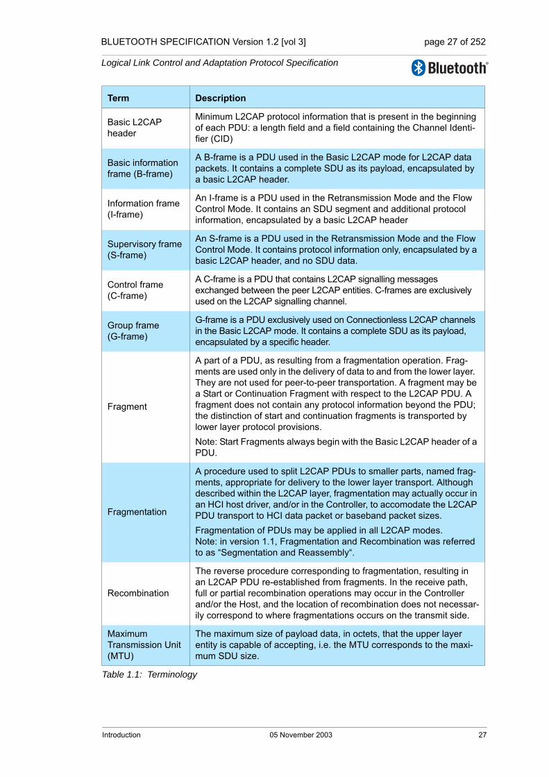
BLUETOOTH SPECIFICATION Version 1.2 [vol 3] page 27 of 252
Logical Link Control and Adaptation Protocol Specification
Basic L2CAP header
Minimum L2CAP protocol information that is present in the beginning of each PDU: a length field and a field containing the Channel Identi-fier (CID)
Basic information frame (B-frame)
A B-frame is a PDU used in the Basic L2CAP mode for L2CAP data packets. It contains a complete SDU as its payload, encapsulated by a basic L2CAP header.
Information frame (I-frame)
An I-frame is a PDU used in the Retransmission Mode and the Flow Control Mode. It contains an SDU segment and additional protocol information, encapsulated by a basic L2CAP header
Supervisory frame (S-frame)
An S-frame is a PDU used in the Retransmission Mode and the Flow Control Mode. It contains protocol information only, encapsulated by a basic L2CAP header, and no SDU data.
Control frame (C-frame)
A C-frame is a PDU that contains L2CAP signalling messages exchanged between the peer L2CAP entities. C-frames are exclusively used on the L2CAP signalling channel.
Group frame (G-frame)
G-frame is a PDU exclusively used on Connectionless L2CAP channels in the Basic L2CAP mode. It contains a complete SDU as its payload, encapsulated by a specific header.
Fragment
A part of a PDU, as resulting from a fragmentation operation. Frag-ments are used only in the delivery of data to and from the lower layer. They are not used for peer-to-peer transportation. A fragment may be a Start or Continuation Fragment with respect to the L2CAP PDU. A fragment does not contain any protocol information beyond the PDU; the distinction of start and continuation fragments is transported by lower layer protocol provisions. Note: Start Fragments always begin with the Basic L2CAP header of a PDU.
Fragmentation
A procedure used to split L2CAP PDUs to smaller parts, named frag-ments, appropriate for delivery to the lower layer transport. Although described within the L2CAP layer, fragmentation may actually occur in an HCI host driver, and/or in the Controller, to accomodate the L2CAP PDU transport to HCI data packet or baseband packet sizes.Fragmentation of PDUs may be applied in all L2CAP modes. Note: in version 1.1, Fragmentation and Recombination was referred to as “Segmentation and Reassembly“.
Recombination
The reverse procedure corresponding to fragmentation, resulting in an L2CAP PDU re-established from fragments. In the receive path, full or partial recombination operations may occur in the Controller and/or the Host, and the location of recombination does not necessar-ily correspond to where fragmentations occurs on the transmit side.
Maximum Transmission Unit (MTU)
The maximum size of payload data, in octets, that the upper layer entity is capable of accepting, i.e. the MTU corresponds to the maxi-mum SDU size.
Term Description
Table 1.1: Terminology
Introduction 05 November 2003 27

BLUETOOTH SPECIFICATION Version 1.2 [vol 3] page 28 of 252
Logical Link Control and Adaptation Protocol Specification
Maximum PDU payload Size (MPS)
The maximum size of payload data in octets that the L2CAP layer entity is capable of accepting, i.e. the MPS corresponds to the maxi-mum PDU payload size. Note: in the absence of segmentation, or in the Basic L2CAP Mode, the Maximum Transmission Unit is the equivalent to the Maximum PDU payload Size and shall be made equal in the configuration parameters.
Signalling MTU (MTUsig)
The maximum size of command information that the L2CAP layer entity is capable of accepting. The MTUsig, refers to the signalling channel only and corresponds to the maximum size of a C-frame, excluding the Basic L2CAP header. The MTUsig value of a peer is dis-covered when a C-frame that is too large is rejected by the peer.
Connectionless MTU (MTUcnl)
The maximum size of the connection packet information that the L2CAP layer entity is capable of accepting. The MTUcnl refers to the connectionless channel only and corresponds to the maximum G-frame, excluding the Basic L2CAP header. The MTUcnl of a peer can be discovered by sending an Information Request.
MaxTransmit
In Retransmission mode, MaxTransmit controls the number of trans-missions of a PDU that L2CAP is allowed to try before assuming that the PDU (and the link) is lost. The minimum value is 1 (only 1 trans-mission permitted).Note: Setting MaxTransmit to 1 prohibits PDU retransmissions. Fail-ure of a single PDU will cause the link to drop. By comparison, in Flow Control mode, failure of a single PDU will not necessarily cause the link to drop.
Term Description
Table 1.1: Terminology
28 05 November 2003 Introduction
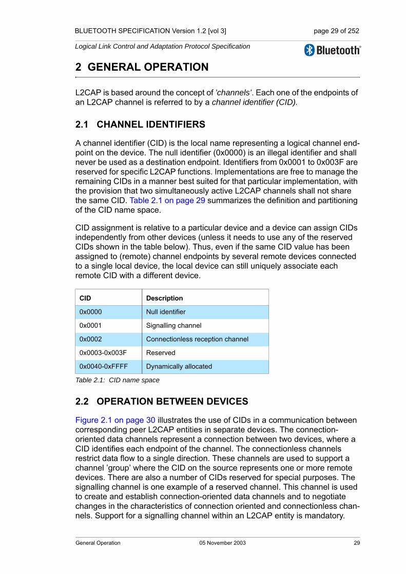
BLUETOOTH SPECIFICATION Version 1.2 [vol 3] page 29 of 252
Logical Link Control and Adaptation Protocol Specification
2 GENERAL OPERATION
L2CAP is based around the concept of ’channels’. Each one of the endpoints of an L2CAP channel is referred to by a channel identifier (CID).
2.1 CHANNEL IDENTIFIERS
A channel identifier (CID) is the local name representing a logical channel end-point on the device. The null identifier (0x0000) is an illegal identifier and shall never be used as a destination endpoint. Identifiers from 0x0001 to 0x003F are reserved for specific L2CAP functions. Implementations are free to manage the remaining CIDs in a manner best suited for that particular implementation, with the provision that two simultaneously active L2CAP channels shall not share the same CID. Table 2.1 on page 29 summarizes the definition and partitioning of the CID name space.
CID assignment is relative to a particular device and a device can assign CIDs independently from other devices (unless it needs to use any of the reserved CIDs shown in the table below). Thus, even if the same CID value has been assigned to (remote) channel endpoints by several remote devices connected to a single local device, the local device can still uniquely associate each remote CID with a different device.
2.2 OPERATION BETWEEN DEVICES
Figure 2.1 on page 30 illustrates the use of CIDs in a communication between corresponding peer L2CAP entities in separate devices. The connection-oriented data channels represent a connection between two devices, where a CID identifies each endpoint of the channel. The connectionless channels restrict data flow to a single direction. These channels are used to support a channel ’group’ where the CID on the source represents one or more remote devices. There are also a number of CIDs reserved for special purposes. The signalling channel is one example of a reserved channel. This channel is used to create and establish connection-oriented data channels and to negotiate changes in the characteristics of connection oriented and connectionless chan-nels. Support for a signalling channel within an L2CAP entity is mandatory.
CID Description
0x0000 Null identifier
0x0001 Signalling channel
0x0002 Connectionless reception channel
0x0003-0x003F Reserved
0x0040-0xFFFF Dynamically allocated
Table 2.1: CID name space
General Operation 05 November 2003 29
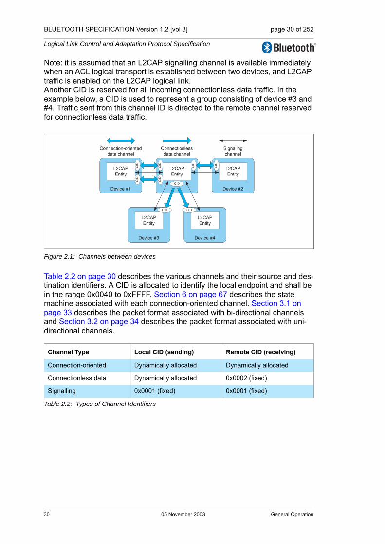
BLUETOOTH SPECIFICATION Version 1.2 [vol 3] page 30 of 252
Logical Link Control and Adaptation Protocol Specification
Note: it is assumed that an L2CAP signalling channel is available immediately when an ACL logical transport is established between two devices, and L2CAP traffic is enabled on the L2CAP logical link.Another CID is reserved for all incoming connectionless data traffic. In the example below, a CID is used to represent a group consisting of device #3 and #4. Traffic sent from this channel ID is directed to the remote channel reserved for connectionless data traffic.
Figure 2.1: Channels between devices
Table 2.2 on page 30 describes the various channels and their source and des-tination identifiers. A CID is allocated to identify the local endpoint and shall be in the range 0x0040 to 0xFFFF. Section 6 on page 67 describes the state machine associated with each connection-oriented channel. Section 3.1 on page 33 describes the packet format associated with bi-directional channels and Section 3.2 on page 34 describes the packet format associated with uni-directional channels.
Channel Type Local CID (sending) Remote CID (receiving)
Connection-oriented Dynamically allocated Dynamically allocated
Connectionless data Dynamically allocated 0x0002 (fixed)
Signalling 0x0001 (fixed) 0x0001 (fixed)
Table 2.2: Types of Channel Identifiers
L2CAPEntity
L2CAPEntity
Device #1
L2CAPEntity
Device #2
L2CAPEntity
Device #3
L2CAPEntity
Device #4
CID
CID
CID
Connection-orienteddata channel
Connectionlessdata channel
Signalingchannel
CID
CID
CID CID
CID
CID
30 05 November 2003 General Operation
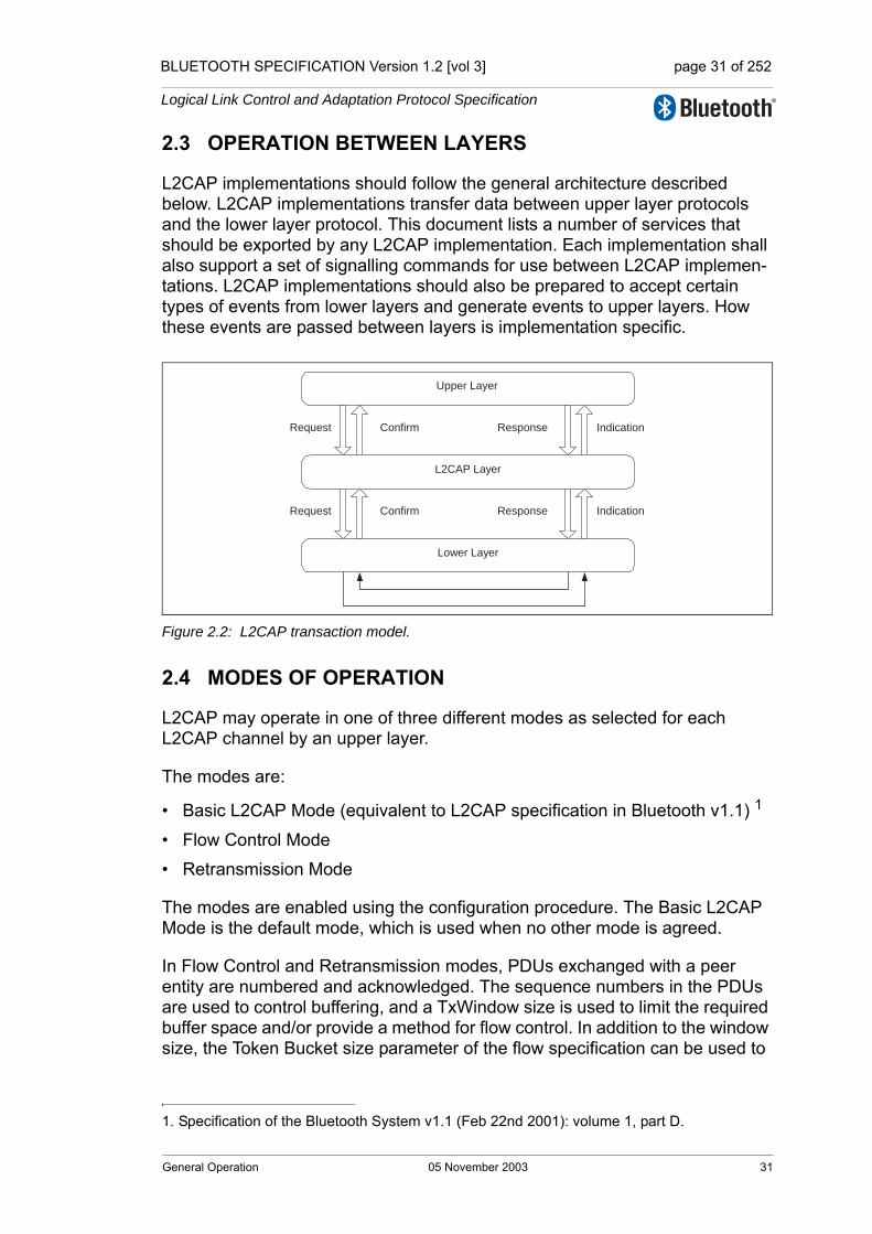
BLUETOOTH SPECIFICATION Version 1.2 [vol 3] page 31 of 252
Logical Link Control and Adaptation Protocol Specification
2.3 OPERATION BETWEEN LAYERS
L2CAP implementations should follow the general architecture described below. L2CAP implementations transfer data between upper layer protocols and the lower layer protocol. This document lists a number of services that should be exported by any L2CAP implementation. Each implementation shall also support a set of signalling commands for use between L2CAP implemen-tations. L2CAP implementations should also be prepared to accept certain types of events from lower layers and generate events to upper layers. How these events are passed between layers is implementation specific.
Figure 2.2: L2CAP transaction model.
2.4 MODES OF OPERATION
L2CAP may operate in one of three different modes as selected for each L2CAP channel by an upper layer.
The modes are:
• Basic L2CAP Mode (equivalent to L2CAP specification in Bluetooth v1.1) 1
• Flow Control Mode
• Retransmission Mode
The modes are enabled using the configuration procedure. The Basic L2CAP Mode is the default mode, which is used when no other mode is agreed.
In Flow Control and Retransmission modes, PDUs exchanged with a peer entity are numbered and acknowledged. The sequence numbers in the PDUs are used to control buffering, and a TxWindow size is used to limit the required buffer space and/or provide a method for flow control. In addition to the window size, the Token Bucket size parameter of the flow specification can be used to
1. Specification of the Bluetooth System v1.1 (Feb 22nd 2001): volume 1, part D.
Lower Layer
L2CAP Layer
Upper Layer
Request IndicationConfirm Response
Response IndicationRequest Confirm
General Operation 05 November 2003 31

BLUETOOTH SPECIFICATION Version 1.2 [vol 3] page 32 of 252
Logical Link Control and Adaptation Protocol Specification
dimension the buffers; in particular on channels that do not use flow and error control.
In Flow Control Mode no retransmissions take place, but missing PDUs are detected and can be reported as lost.
In Retransmission Mode a timer is used to ensure that all PDUs are delivered to the peer, by retransmiting PDUs as needed. A go-back-n repeat mechanism is used to simplify the protocol and limit the buffering requirements.
32 05 November 2003 General Operation

BLUETOOTH SPECIFICATION Version 1.2 [vol 3] page 33 of 252
Logical Link Control and Adaptation Protocol Specification
3 DATA PACKET FORMAT
L2CAP is packet-based but follows a communication model based on chan-nels. A channel represents a data flow between L2CAP entities in remote devices. Channels may be connection-oriented or connectionless. All packet fields shall use Little Endian byte order.
3.1 CONNECTION-ORIENTED CHANNEL IN BASIC L2CAP MODE
Figure 3.1 on page 33 illustrates the format of the L2CAP PDU within a con-nection-oriented channel. In basic L2CAP mode, the L2CAP PDU on a connec-tion-oriented channel is also referred to as a "B-frame".
Figure 3.1: PDU format in Basic L2CAP mode on connection-oriented channels (field sizes in bits)
The fields shown are:
• Length: 2 octets (16 bits)Length indicates the size of the information payload in octets, excluding the length of the L2CAP header. The length of an information payload can be up to 65535 octets. The Length field is used for recombination and serves as a simple integrity check of the recombined L2CAP packet on the receiving end.
• Channel ID: 2 octetsThe channel ID (CID) identifies the destination channel endpoint of the packet.
• Information payload: 0 to 65535 octetsThis contains the payload received from the upper layer protocol (outgoing packet), or delivered to the upper layer protocol (incoming packet). The MTU is determined during channel configuration (see Section 5.1 on page 57). The minimum supported MTU for the signalling PDUs (MTUsig) is 48 octets (see Section 4 on page 41).
LengthChannel
IDInformation payload
Basic L2CAP
header
16 16LSB MSB
Basic information frame (B-frame)
Data Packet Format 05 November 2003 33
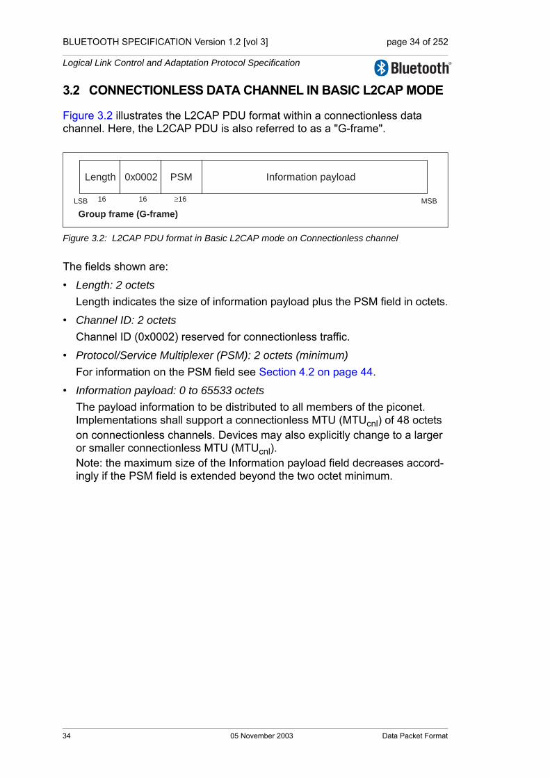
BLUETOOTH SPECIFICATION Version 1.2 [vol 3] page 34 of 252
Logical Link Control and Adaptation Protocol Specification
3.2 CONNECTIONLESS DATA CHANNEL IN BASIC L2CAP MODE
Figure 3.2 illustrates the L2CAP PDU format within a connectionless data channel. Here, the L2CAP PDU is also referred to as a "G-frame".
Figure 3.2: L2CAP PDU format in Basic L2CAP mode on Connectionless channel
The fields shown are:
• Length: 2 octetsLength indicates the size of information payload plus the PSM field in octets.
• Channel ID: 2 octetsChannel ID (0x0002) reserved for connectionless traffic.
• Protocol/Service Multiplexer (PSM): 2 octets (minimum)For information on the PSM field see Section 4.2 on page 44.
• Information payload: 0 to 65533 octetsThe payload information to be distributed to all members of the piconet. Implementations shall support a connectionless MTU (MTUcnl) of 48 octets on connectionless channels. Devices may also explicitly change to a larger or smaller connectionless MTU (MTUcnl).Note: the maximum size of the Information payload field decreases accord-ingly if the PSM field is extended beyond the two octet minimum.
Length 0x0002 Information payload
16 16LSB MSB
PSM
≥16
Group frame (G-frame)
34 05 November 2003 Data Packet Format
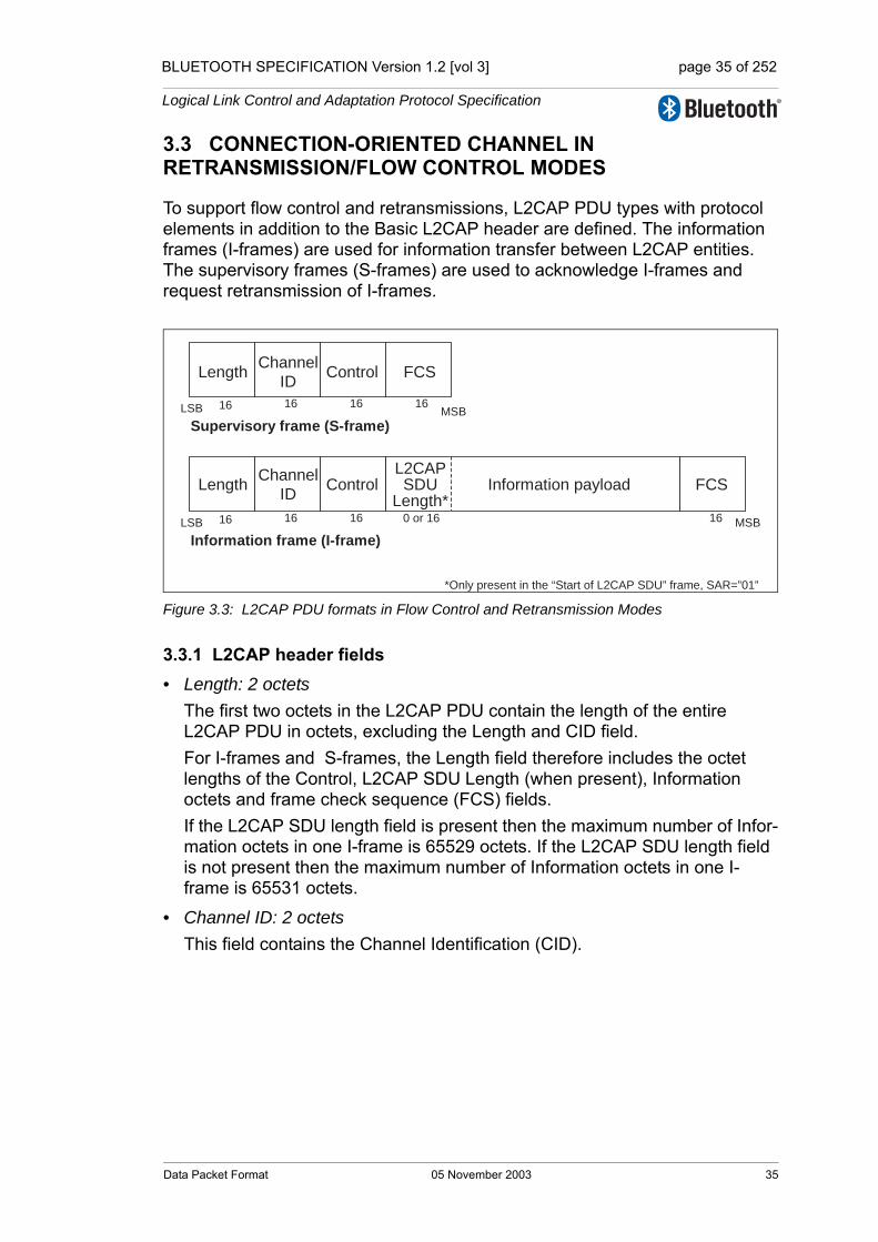
BLUETOOTH SPECIFICATION Version 1.2 [vol 3] page 35 of 252
Logical Link Control and Adaptation Protocol Specification
3.3 CONNECTION-ORIENTED CHANNEL IN RETRANSMISSION/FLOW CONTROL MODES
To support flow control and retransmissions, L2CAP PDU types with protocol elements in addition to the Basic L2CAP header are defined. The information frames (I-frames) are used for information transfer between L2CAP entities. The supervisory frames (S-frames) are used to acknowledge I-frames and request retransmission of I-frames.
Figure 3.3: L2CAP PDU formats in Flow Control and Retransmission Modes
3.3.1 L2CAP header fields• Length: 2 octets
The first two octets in the L2CAP PDU contain the length of the entire L2CAP PDU in octets, excluding the Length and CID field. For I-frames and S-frames, the Length field therefore includes the octet lengths of the Control, L2CAP SDU Length (when present), Information octets and frame check sequence (FCS) fields.If the L2CAP SDU length field is present then the maximum number of Infor-mation octets in one I-frame is 65529 octets. If the L2CAP SDU length field is not present then the maximum number of Information octets in one I-frame is 65531 octets.
• Channel ID: 2 octetsThis field contains the Channel Identification (CID).
LengthChannel
ID
16 16LSB MSB
Control FCS
16 16
LengthChannel
IDInformation payload
16 16LSB MSB
Control FCS
16 16
Supervisory frame (S-frame)
Information frame (I-frame)
L2CAPSDU
Length*0 or 16
*Only present in the “Start of L2CAP SDU” frame, SAR=”01”
Data Packet Format 05 November 2003 35
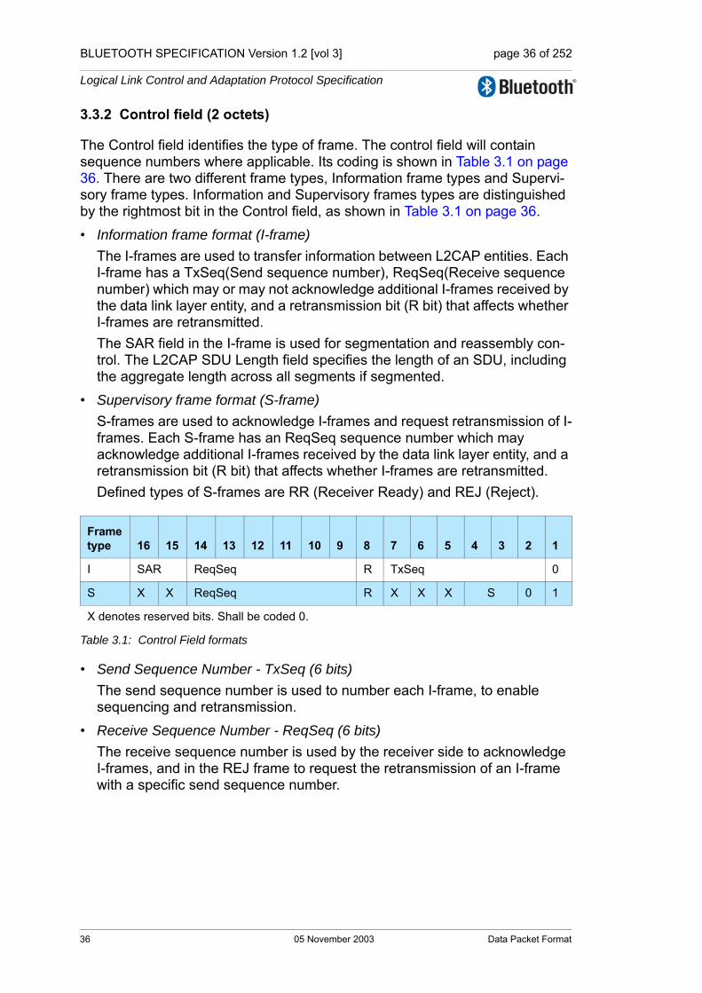
BLUETOOTH SPECIFICATION Version 1.2 [vol 3] page 36 of 252
Logical Link Control and Adaptation Protocol Specification
3.3.2 Control field (2 octets)
The Control field identifies the type of frame. The control field will contain sequence numbers where applicable. Its coding is shown in Table 3.1 on page 36. There are two different frame types, Information frame types and Supervi-sory frame types. Information and Supervisory frames types are distinguished by the rightmost bit in the Control field, as shown in Table 3.1 on page 36.
• Information frame format (I-frame)The I-frames are used to transfer information between L2CAP entities. Each I-frame has a TxSeq(Send sequence number), ReqSeq(Receive sequence number) which may or may not acknowledge additional I-frames received by the data link layer entity, and a retransmission bit (R bit) that affects whether I-frames are retransmitted. The SAR field in the I-frame is used for segmentation and reassembly con-trol. The L2CAP SDU Length field specifies the length of an SDU, including the aggregate length across all segments if segmented.
• Supervisory frame format (S-frame)S-frames are used to acknowledge I-frames and request retransmission of I-frames. Each S-frame has an ReqSeq sequence number which may acknowledge additional I-frames received by the data link layer entity, and a retransmission bit (R bit) that affects whether I-frames are retransmitted. Defined types of S-frames are RR (Receiver Ready) and REJ (Reject).
• Send Sequence Number - TxSeq (6 bits)The send sequence number is used to number each I-frame, to enable sequencing and retransmission.
• Receive Sequence Number - ReqSeq (6 bits)The receive sequence number is used by the receiver side to acknowledge I-frames, and in the REJ frame to request the retransmission of an I-frame with a specific send sequence number.
Frametype 16 15 14 13 12 11 10 9 8 7 6 5 4 3 2 1
I SAR ReqSeq R TxSeq 0
S X X ReqSeq R X X X S 0 1
X denotes reserved bits. Shall be coded 0.
Table 3.1: Control Field formats
36 05 November 2003 Data Packet Format
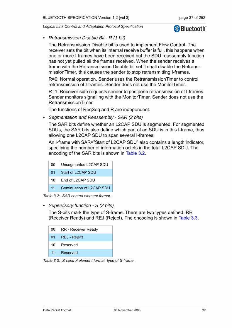
BLUETOOTH SPECIFICATION Version 1.2 [vol 3] page 37 of 252
Logical Link Control and Adaptation Protocol Specification
• Retransmission Disable Bit - R (1 bit)The Retransmission Disable bit is used to implement Flow Control. The receiver sets the bit when its internal receive buffer is full, this happens when one or more I-frames have been received but the SDU reassembly function has not yet pulled all the frames received. When the sender receives a frame with the Retransmission Disable bit set it shall disable the Retrans-missionTimer, this causes the sender to stop retransmitting I-frames.R=0: Normal operation. Sender uses the RetransmissionTimer to control retransmission of I-frames. Sender does not use the MonitorTimer.R=1: Receiver side requests sender to postpone retransmission of I-frames. Sender monitors signalling with the MonitorTimer. Sender does not use the RetransmissionTimer. The functions of ReqSeq and R are independent.
• Segmentation and Reassembly - SAR (2 bits)The SAR bits define whether an L2CAP SDU is segmented. For segmented SDUs, the SAR bits also define which part of an SDU is in this I-frame, thus allowing one L2CAP SDU to span several I-frames. An I-frame with SAR=”Start of L2CAP SDU” also contains a length indicator, specifying the number of information octets in the total L2CAP SDU. The encoding of the SAR bits is shown in Table 3.2.
• Supervisory function - S (2 bits)The S-bits mark the type of S-frame. There are two types defined: RR (Receiver Ready) and REJ (Reject). The encoding is shown in Table 3.3.
00 Unsegmented L2CAP SDU
01 Start of L2CAP SDU
10 End of L2CAP SDU
11 Continuation of L2CAP SDU
Table 3.2: SAR control element format.
00 RR - Receiver Ready
01 REJ - Reject
10 Reserved
11 Reserved
Table 3.3: S control element format: type of S-frame.
Data Packet Format 05 November 2003 37
BLUETOOTH SPECIFICATION Version 1.2 [vol 3] page 38 of 252
Logical Link Control and Adaptation Protocol Specification
3.3.3 L2CAP SDU length field (2 octets)
When a SDU spans more than one I-frame, the first I-frame in the sequence shall be identified by SAR=01=”Start of L2CAP SDU”. The L2CAP SDU Length field shall specify the total number of octets in the SDU. The L2CAP SDU Length field shall be present in I-frames with SAR=01 (Start of L2CAP SDU), and shall not be used in any other I-frames. When the SDU is unsegmented (SAR=00), L2CAP SDU Length field is not needed and shall not be present.
3.3.4 Information payload field (0 to 65531 octets)
The information payload field consists of an integral number of octets. The maximum number of octets in this field is the same as the negotiated value of the MPS configuration parameter. The maximum number of octets in this field is also limited by the range of the basic L2CAP header length field. For I-frames without an SDU length field, this limits the maximum number of octets in the field to 65531. For I-frames with an SDU length field, SAR=01, this limits maximum number of octets in the field to 65529. Thus, even if an MPS of 65531 has been negotiated, the range of the basic L2CAP header length field will restrict the number of octets in this field when an SDU length field is present to 65529.
38 05 November 2003 Data Packet Format
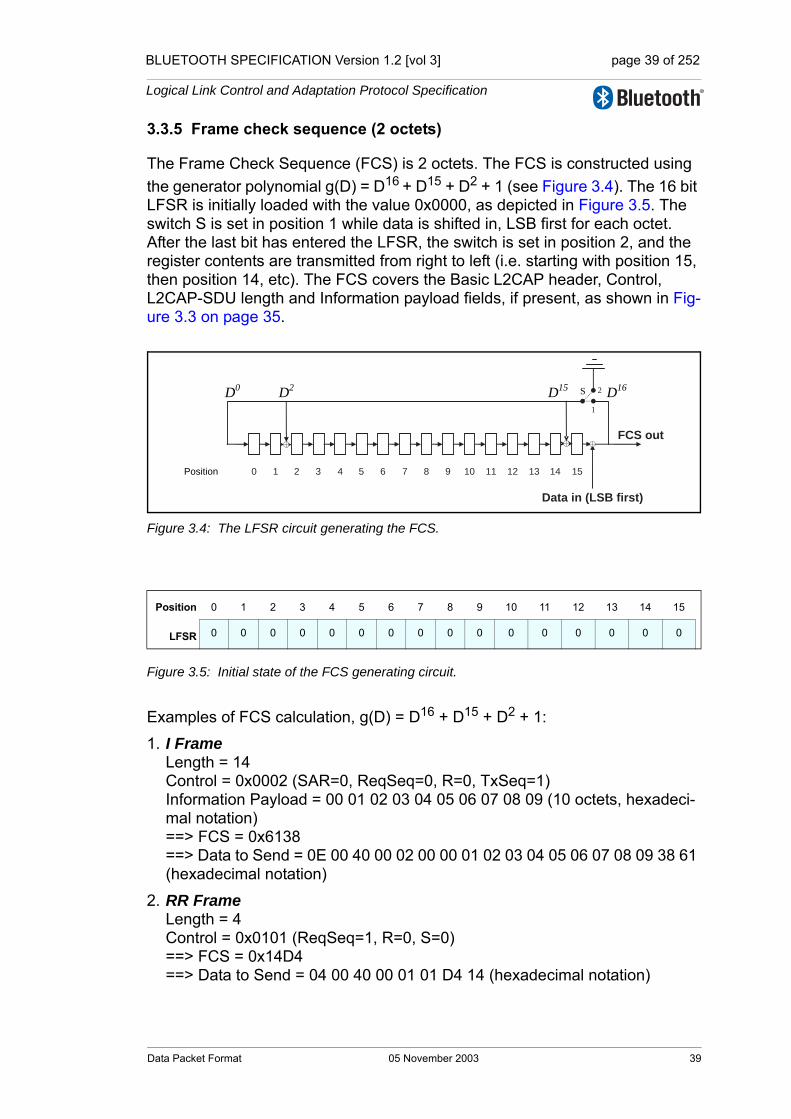
BLUETOOTH SPECIFICATION Version 1.2 [vol 3] page 39 of 252
Logical Link Control and Adaptation Protocol Specification
3.3.5 Frame check sequence (2 octets)
The Frame Check Sequence (FCS) is 2 octets. The FCS is constructed using the generator polynomial g(D) = D16 + D15 + D2 + 1 (see Figure 3.4). The 16 bit LFSR is initially loaded with the value 0x0000, as depicted in Figure 3.5. The switch S is set in position 1 while data is shifted in, LSB first for each octet. After the last bit has entered the LFSR, the switch is set in position 2, and the register contents are transmitted from right to left (i.e. starting with position 15, then position 14, etc). The FCS covers the Basic L2CAP header, Control, L2CAP-SDU length and Information payload fields, if present, as shown in Fig-ure 3.3 on page 35.
Figure 3.4: The LFSR circuit generating the FCS.
Figure 3.5: Initial state of the FCS generating circuit.
Examples of FCS calculation, g(D) = D16 + D15 + D2 + 1:
1. I Frame Length = 14 Control = 0x0002 (SAR=0, ReqSeq=0, R=0, TxSeq=1) Information Payload = 00 01 02 03 04 05 06 07 08 09 (10 octets, hexadeci-mal notation) ==> FCS = 0x6138 ==> Data to Send = 0E 00 40 00 02 00 00 01 02 03 04 05 06 07 08 09 38 61 (hexadecimal notation)
2. RR Frame Length = 4 Control = 0x0101 (ReqSeq=1, R=0, S=0) ==> FCS = 0x14D4 ==> Data to Send = 04 00 40 00 01 01 D4 14 (hexadecimal notation)
Position 0 1 2 3 4 5 6 7 8 9 10 11 12 13 14 15
LFSR 0 0 0 0 0 0 0 0 0 0 0 0 0 0 0 0
D0 D2 D15 D16S
Position 130 1 2 3 4 5 6 7 8 9 10 11 12 14 15
1
2
Data in (LSB first)
FCS out
Data Packet Format 05 November 2003 39

BLUETOOTH SPECIFICATION Version 1.2 [vol 3] page 40 of 252
Logical Link Control and Adaptation Protocol Specification
3.3.6 Invalid frame detection
A received PDU shall be regarded as invalid, if one of the following conditions occurs:
1. Contains an unknown CID.
2. Contains an FCS error. 3. Contains a length greater than the maximum PDU payload size (MPS).4. I-frame that has fewer than 8 octets. 5. I-frame with SAR=01 (Start of L2CAP SDU) that has fewer than 10 octets.6. I-frame with SAR bits that do not correspond to a normal sequence of either
unsegmented or start, continuation, end for the given CID.7. S-frame where the length field is not equal to 4.
These error conditions may be used for error reporting.
40 05 November 2003 Data Packet Format

BLUETOOTH SPECIFICATION Version 1.2 [vol 3] page 41 of 252
Logical Link Control and Adaptation Protocol Specification
4 SIGNALLING PACKET FORMATS
This section describes the signalling commands passed between two L2CAP entities on peer devices. All signalling commands are sent to the signalling channel with CID 0x0001. This signalling channel is available as soon as an ACL logical transport is set up and L2CAP traffic is enabled on the L2CAP log-ical link. Figure 4.1 on page 41 illustrates the general format of L2CAP PDUs containing signalling commands (C-frames). Multiple commands may be sent in a single C-frame. Commands take the form of Requests and Responses. All L2CAP implementations shall support the reception of C-frames with a payload length that does not exceed the signaling MTU. The minimum supported pay-load length for the C-frame (MTUsig) is 48 octets. L2CAP implementations should not use C-frames that exceed the MTUsig of the peer device. If they ever do, the peer device shall send a Command Reject containing the sup-ported MTUsig. Implementations must be able to handle the reception of multi-ple commands in an L2CAP packet.
Figure 4.1: L2CAP PDU format on the signalling channel
Figure 4.2 displays the general format of all signalling commands.
Figure 4.2: Command format
LengthChannel
ID = 0x0001
Commands
16 16LSB MSB
Control frame (C-frame)
LengthCode Identifier
data
LSB MSBoctet 0 octet 1 octet 2 octet 3
Signalling Packet Formats 05 November 2003 41

BLUETOOTH SPECIFICATION Version 1.2 [vol 3] page 42 of 252
Logical Link Control and Adaptation Protocol Specification
The fields shown are:
• Code (1 octet)The Code field is one octet long and identifies the type of command. When a packet is received with an unknown Code field, a Command Reject packet (defined in Section 4.1 on page 43) is sent in response.Table 4.1 on page 42 lists the codes defined by this document. All codes are specified with the most significant bit in the left-most position.
• Identifier (1 octet)The Identifier field is one octet long and matches responses with requests. The requesting device sets this field and the responding device uses the same value in its response. Between any two devices a different Identifier shall be used for each successive command. Following the original trans-mission of an Identifier in a command, the Identifier may be recycled if all other Identifiers have subsequently been used.RTX and ERTX timers are used to determine when the remote end point is not responding to signalling requests. On the expiration of a RTX or ERTX timer, the same identifier shall be used if a duplicate Request is re-sent as stated in Section 6.2 on page 74. A device receiving a duplicate request should reply with a duplicate response. A command response with an invalid identifier is silently dis-carded. Signaling identifier 0x00 is an illegal identifier and shall never be used in any command.
Code Description
0x00 RESERVED
0x01 Command reject
0x02 Connection request
0x03 Connection response
0x04 Configure request
0x05 Configure response
0x06 Disconnection request
0x07 Disconnection response
0x08 Echo request
0x09 Echo response
0x0A Information request
0x0B Information response
Table 4.1: Signalling Command Codes
42 05 November 2003 Signalling Packet Formats
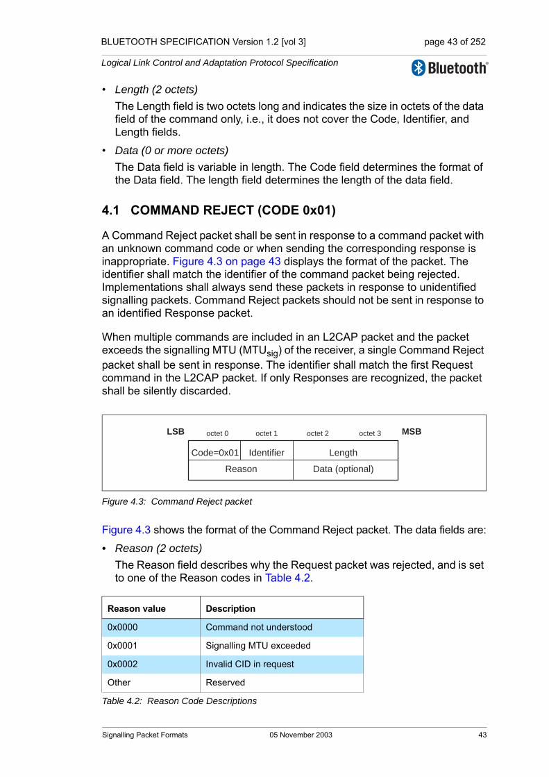
BLUETOOTH SPECIFICATION Version 1.2 [vol 3] page 43 of 252
Logical Link Control and Adaptation Protocol Specification
• Length (2 octets)The Length field is two octets long and indicates the size in octets of the data field of the command only, i.e., it does not cover the Code, Identifier, and Length fields.
• Data (0 or more octets)The Data field is variable in length. The Code field determines the format of the Data field. The length field determines the length of the data field.
4.1 COMMAND REJECT (CODE 0x01)
A Command Reject packet shall be sent in response to a command packet with an unknown command code or when sending the corresponding response is inappropriate. Figure 4.3 on page 43 displays the format of the packet. The identifier shall match the identifier of the command packet being rejected. Implementations shall always send these packets in response to unidentified signalling packets. Command Reject packets should not be sent in response to an identified Response packet.
When multiple commands are included in an L2CAP packet and the packet exceeds the signalling MTU (MTUsig) of the receiver, a single Command Reject packet shall be sent in response. The identifier shall match the first Request command in the L2CAP packet. If only Responses are recognized, the packet shall be silently discarded.
Figure 4.3: Command Reject packet
Figure 4.3 shows the format of the Command Reject packet. The data fields are:
• Reason (2 octets)The Reason field describes why the Request packet was rejected, and is set to one of the Reason codes in Table 4.2.
Reason value Description
0x0000 Command not understood
0x0001 Signalling MTU exceeded
0x0002 Invalid CID in request
Other Reserved
Table 4.2: Reason Code Descriptions
Code=0x01 LengthIdentifier
LSB MSBoctet 0 octet 1 octet 2 octet 3
Reason Data (optional)
Signalling Packet Formats 05 November 2003 43
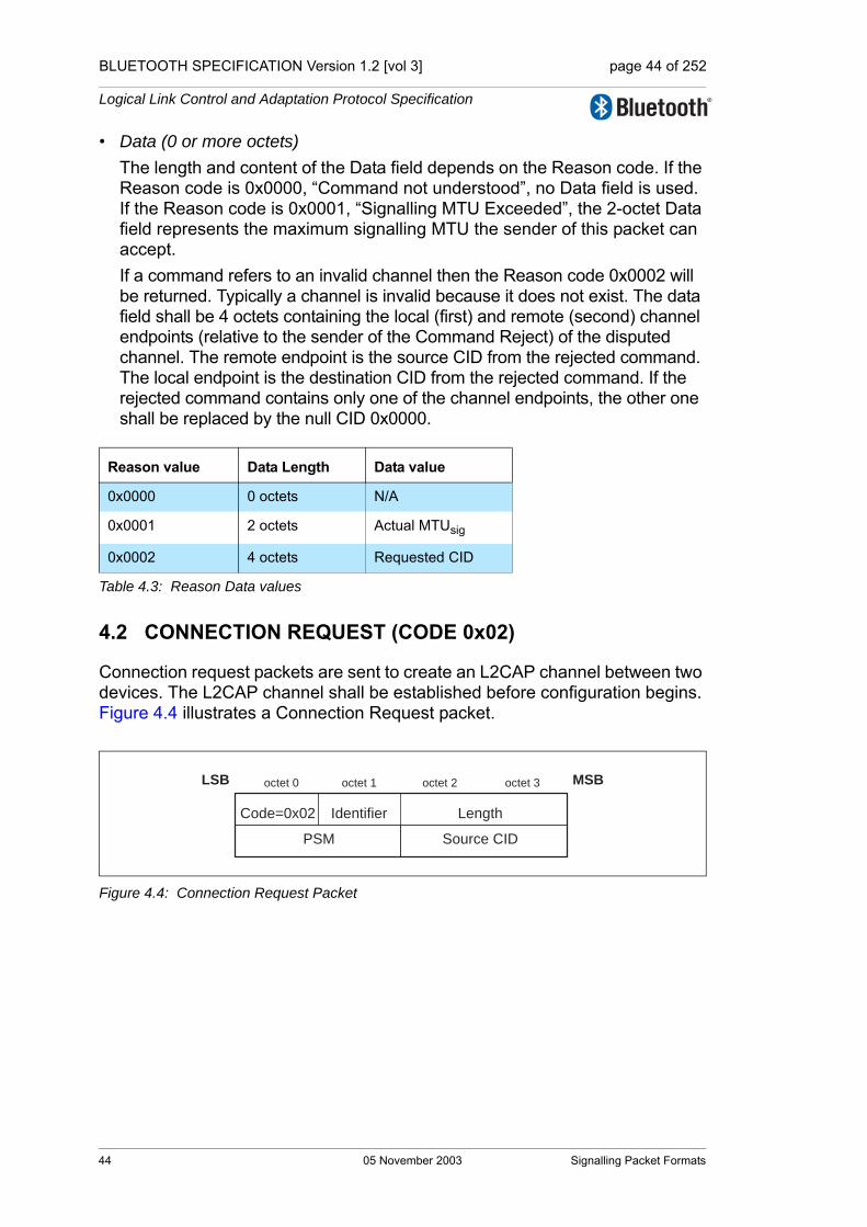
BLUETOOTH SPECIFICATION Version 1.2 [vol 3] page 44 of 252
Logical Link Control and Adaptation Protocol Specification
• Data (0 or more octets)The length and content of the Data field depends on the Reason code. If the Reason code is 0x0000, “Command not understood”, no Data field is used. If the Reason code is 0x0001, “Signalling MTU Exceeded”, the 2-octet Data field represents the maximum signalling MTU the sender of this packet can accept.If a command refers to an invalid channel then the Reason code 0x0002 will be returned. Typically a channel is invalid because it does not exist. The data field shall be 4 octets containing the local (first) and remote (second) channel endpoints (relative to the sender of the Command Reject) of the disputed channel. The remote endpoint is the source CID from the rejected command. The local endpoint is the destination CID from the rejected command. If the rejected command contains only one of the channel endpoints, the other one shall be replaced by the null CID 0x0000.
4.2 CONNECTION REQUEST (CODE 0x02)
Connection request packets are sent to create an L2CAP channel between two devices. The L2CAP channel shall be established before configuration begins. Figure 4.4 illustrates a Connection Request packet.
Figure 4.4: Connection Request Packet
Reason value Data Length Data value
0x0000 0 octets N/A
0x0001 2 octets Actual MTUsig
0x0002 4 octets Requested CID
Table 4.3: Reason Data values
Code=0x02 LengthIdentifier
LSB MSBoctet 0 octet 1 octet 2 octet 3
PSM Source CID
44 05 November 2003 Signalling Packet Formats
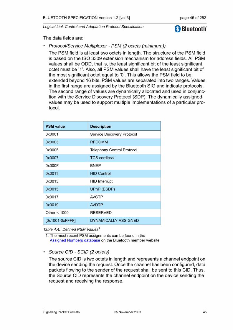
BLUETOOTH SPECIFICATION Version 1.2 [vol 3] page 45 of 252
Logical Link Control and Adaptation Protocol Specification
The data fields are:
• Protocol/Service Multiplexor - PSM (2 octets (minimum))The PSM field is at least two octets in length. The structure of the PSM field is based on the ISO 3309 extension mechanism for address fields. All PSM values shall be ODD, that is, the least significant bit of the least significant octet must be ’1’. Also, all PSM values shall have the least significant bit of the most significant octet equal to ’0’. This allows the PSM field to be extended beyond 16 bits. PSM values are separated into two ranges. Values in the first range are assigned by the Bluetooth SIG and indicate protocols. The second range of values are dynamically allocated and used in conjunc-tion with the Service Discovery Protocol (SDP). The dynamically assigned values may be used to support multiple implementations of a particular pro-tocol.
• Source CID - SCID (2 octets)The source CID is two octets in length and represents a channel endpoint on the device sending the request. Once the channel has been configured, data packets flowing to the sender of the request shall be sent to this CID. Thus, the Source CID represents the channel endpoint on the device sending the request and receiving the response.
PSM value Description
0x0001 Service Discovery Protocol
0x0003 RFCOMM
0x0005 Telephony Control Protocol
0x0007 TCS cordless
0x000F BNEP
0x0011 HID Control
0x0013 HID Interrupt
0x0015 UPnP (ESDP)
0x0017 AVCTP
0x0019 AVDTP
Other < 1000 RESERVED
[0x1001-0xFFFF] DYNAMICALLY ASSIGNED
Table 4.4: Defined PSM Values1
1. The most recent PSM assignments can be found in the Assigned Numbers database on the Bluetooth member website.
Signalling Packet Formats 05 November 2003 45

BLUETOOTH SPECIFICATION Version 1.2 [vol 3] page 46 of 252
Logical Link Control and Adaptation Protocol Specification
4.3 CONNECTION RESPONSE (CODE 0x03)
When a device receives a Connection Request packet, it shall send a Connec-tion Response packet. The format of the connection response packet is shown in Figure 4.5.
Figure 4.5: Connection Response Packet
The data fields are:
• Destination Channel Identifier - DCID (2 octets)This field contains the channel endpoint on the device sending this Response packet. Thus, the Destination CID represents the channel end-point on the device receiving the request and sending the response.
• Source Channel Identifier - SCID (2 octets)This field contains the channel endpoint on the device receiving this Response packet. This is copied from the SCID field of the connection request packet.
• Result (2 octets)The result field indicates the outcome of the connection request. The result value of 0x0000 indicates success while a non-zero value indicates the con-nection request failed or is pending. A logical channel is established on the receipt of a successful result. Table 4.5 on page 46 defines values for this field. The DCID and SCID fields shall be ignored when the result field indi-cates the connection was refused.
Value Description
0x0000 Connection successful.
0x0001 Connection pending
0x0002 Connection refused – PSM not supported.
0x0003 Connection refused – security block.
0x0004 Connection refused – no resources available.
Other Reserved.
Table 4.5: Result values
Code=0x03 LengthIdentifier
LSB MSBoctet 0 octet 1 octet 2 octet 3
Destination CID Source CID
Result Status
46 05 November 2003 Signalling Packet Formats
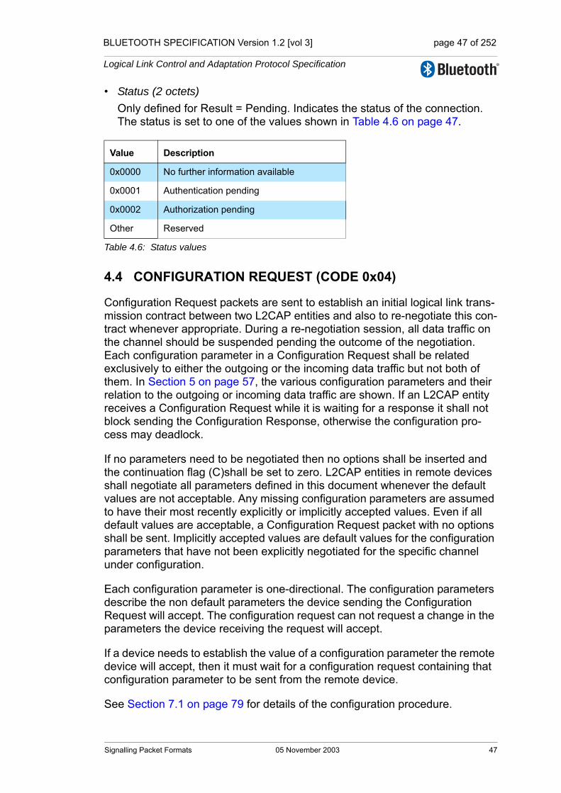
BLUETOOTH SPECIFICATION Version 1.2 [vol 3] page 47 of 252
Logical Link Control and Adaptation Protocol Specification
• Status (2 octets)Only defined for Result = Pending. Indicates the status of the connection. The status is set to one of the values shown in Table 4.6 on page 47.
4.4 CONFIGURATION REQUEST (CODE 0x04)
Configuration Request packets are sent to establish an initial logical link trans-mission contract between two L2CAP entities and also to re-negotiate this con-tract whenever appropriate. During a re-negotiation session, all data traffic on the channel should be suspended pending the outcome of the negotiation. Each configuration parameter in a Configuration Request shall be related exclusively to either the outgoing or the incoming data traffic but not both of them. In Section 5 on page 57, the various configuration parameters and their relation to the outgoing or incoming data traffic are shown. If an L2CAP entity receives a Configuration Request while it is waiting for a response it shall not block sending the Configuration Response, otherwise the configuration pro-cess may deadlock.
If no parameters need to be negotiated then no options shall be inserted and the continuation flag (C)shall be set to zero. L2CAP entities in remote devices shall negotiate all parameters defined in this document whenever the default values are not acceptable. Any missing configuration parameters are assumed to have their most recently explicitly or implicitly accepted values. Even if all default values are acceptable, a Configuration Request packet with no options shall be sent. Implicitly accepted values are default values for the configuration parameters that have not been explicitly negotiated for the specific channel under configuration.
Each configuration parameter is one-directional. The configuration parameters describe the non default parameters the device sending the Configuration Request will accept. The configuration request can not request a change in the parameters the device receiving the request will accept.
If a device needs to establish the value of a configuration parameter the remote device will accept, then it must wait for a configuration request containing that configuration parameter to be sent from the remote device.
See Section 7.1 on page 79 for details of the configuration procedure.
Value Description
0x0000 No further information available
0x0001 Authentication pending
0x0002 Authorization pending
Other Reserved
Table 4.6: Status values
Signalling Packet Formats 05 November 2003 47

BLUETOOTH SPECIFICATION Version 1.2 [vol 3] page 48 of 252
Logical Link Control and Adaptation Protocol Specification
Figure 4.6 defines the format of the Configuration Request packet.
Figure 4.6: Configuration Request Packet
The data fields are:
• Destination CID - DCID (2 octets)This field contains the channel endpoint on the device receiving this Request packet.
• Flags (2 octets)Figure 4.7 shows the two-octet Flags field. Note the most significant bit is shown on the left.
Figure 4.7: Configuration Request Flags field format
Only one flag is defined, the Continuation flag (C).When all configuration options cannot fit into a Configuration Request with length that does not exceed the receiver's MTUsig, the options shall be passed in multiple configuration command packets. If all options fit into the receiver's MTUsig, then they shall be sent in a single configuration request with the continuation flag set to zero. Each Configuration Request shall con-tain an integral number of options - partially formed options shall not be sent in a packet. Each Request shall be tagged with a different Identifier and shall be matched with a Response with the same Identifier. When used in the Configuration Request, the continuation flag indicates the responder should expect to receive multiple request packets. The responder shall reply to each Configuration Request packet. The responder may reply to each Configuration Request with a Configuration Response containing the same option(s) present in the Request (except for those error conditions more appropriate for a Command Reject), or the responder may reply with a "Success" Configuration Response packet containing no options, delaying those options until the full Request has been received. The Configuration Request packet with the continuation flag cleared shall be treated as the Configuration Request event in the channel state machine.
Flags
Code=0x04 LengthIdentifier
LSB MSBoctet 0 octet 1 octet 2 octet 3
Destination CID
Configuration Options
MSB LSB
Reserved C
48 05 November 2003 Signalling Packet Formats

BLUETOOTH SPECIFICATION Version 1.2 [vol 3] page 49 of 252
Logical Link Control and Adaptation Protocol Specification
When used in the Configuration Response, the continuation flag shall be set to one if the flag is set to one in the Request. If the continuation flag is set to one in the Response when the matching Request has the flag set to zero, it indicates the responder has additional options to send to the requestor. In this situation, the requestor shall send null-option Configuration Requests (with continuation flag set to zero) to the responder until the responder replies with a Configuration Response where the continuation flag is set to zero. The Configuration Response packet with the continuation flag set to zero shall be treated as the Configuration Response event in the channel state machine.The result of the configuration transaction is the union of all the result val-ues. All the result values must succeed for the configuration transaction to succeed.Other flags are reserved and shall be set to zero. L2CAP implementations shall ignore these bits.
• Configuration OptionsA list of the parameters and their values to be negotiated shall be provided in the Configuration Options field. These are defined in Section 5 on page 57. A Configuration Request may contain no options (referred to as an empty or null configuration request) and can be used to request a response. For an empty configuration request the length field is set to 0x0004.
Signalling Packet Formats 05 November 2003 49
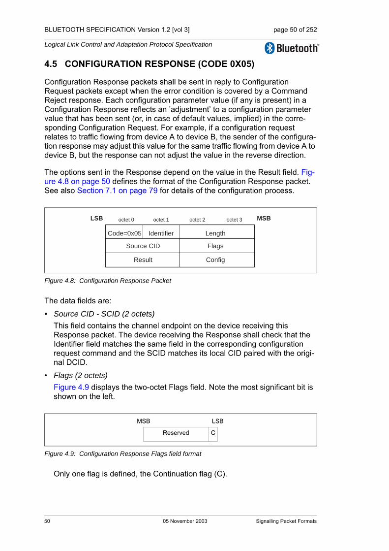
BLUETOOTH SPECIFICATION Version 1.2 [vol 3] page 50 of 252
Logical Link Control and Adaptation Protocol Specification
4.5 CONFIGURATION RESPONSE (CODE 0X05)
Configuration Response packets shall be sent in reply to Configuration Request packets except when the error condition is covered by a Command Reject response. Each configuration parameter value (if any is present) in a Configuration Response reflects an ’adjustment’ to a configuration parameter value that has been sent (or, in case of default values, implied) in the corre-sponding Configuration Request. For example, if a configuration request relates to traffic flowing from device A to device B, the sender of the configura-tion response may adjust this value for the same traffic flowing from device A to device B, but the response can not adjust the value in the reverse direction.
The options sent in the Response depend on the value in the Result field. Fig-ure 4.8 on page 50 defines the format of the Configuration Response packet. See also Section 7.1 on page 79 for details of the configuration process.
Figure 4.8: Configuration Response Packet
The data fields are:
• Source CID - SCID (2 octets)This field contains the channel endpoint on the device receiving this Response packet. The device receiving the Response shall check that the Identifier field matches the same field in the corresponding configuration request command and the SCID matches its local CID paired with the origi-nal DCID.
• Flags (2 octets)Figure 4.9 displays the two-octet Flags field. Note the most significant bit is shown on the left.
Figure 4.9: Configuration Response Flags field format
Only one flag is defined, the Continuation flag (C).
Code=0x05 LengthIdentifier
LSB MSBoctet 0 octet 1 octet 2 octet 3
Source CID Flags
Result Config
MSB LSB
Reserved C
50 05 November 2003 Signalling Packet Formats
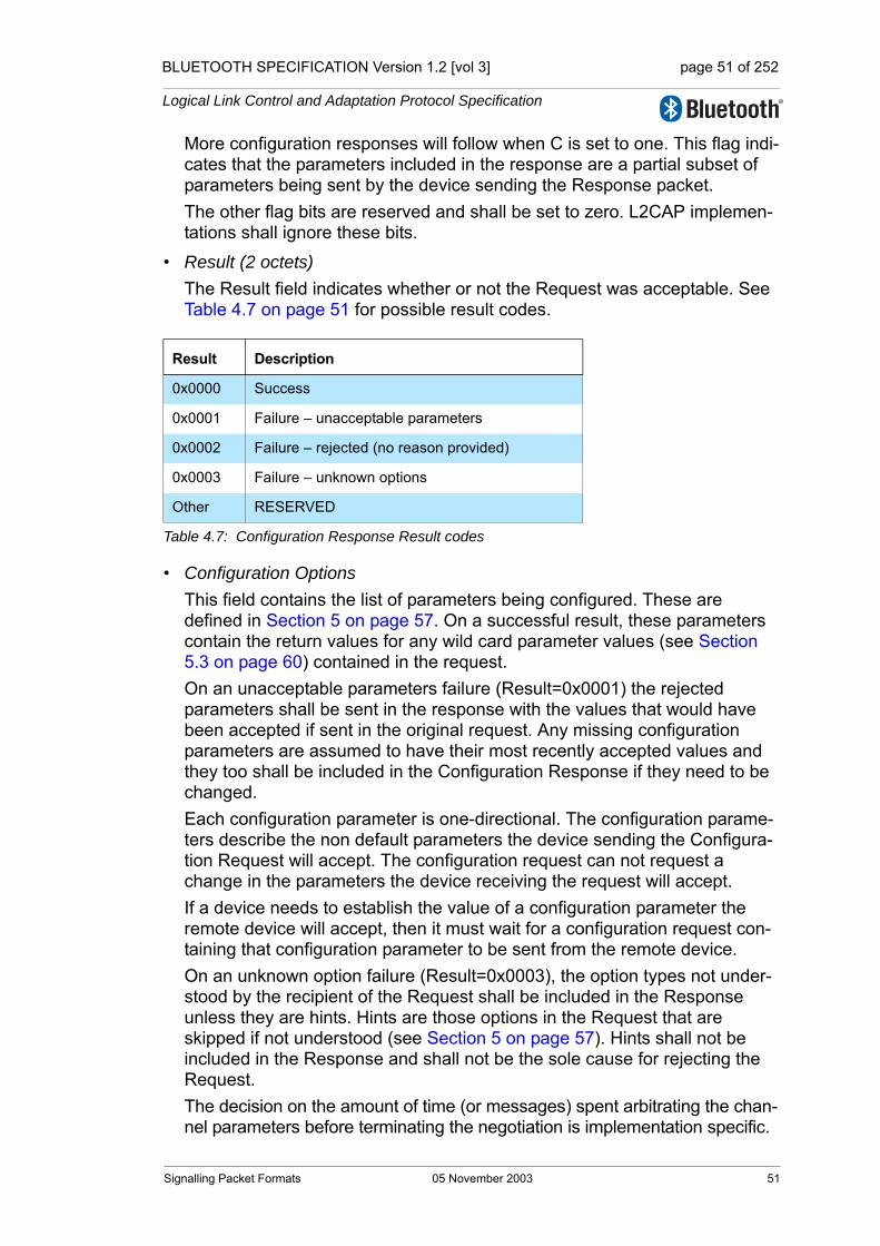
BLUETOOTH SPECIFICATION Version 1.2 [vol 3] page 51 of 252
Logical Link Control and Adaptation Protocol Specification
More configuration responses will follow when C is set to one. This flag indi-cates that the parameters included in the response are a partial subset of parameters being sent by the device sending the Response packet.The other flag bits are reserved and shall be set to zero. L2CAP implemen-tations shall ignore these bits.
• Result (2 octets)The Result field indicates whether or not the Request was acceptable. See Table 4.7 on page 51 for possible result codes.
• Configuration OptionsThis field contains the list of parameters being configured. These are defined in Section 5 on page 57. On a successful result, these parameters contain the return values for any wild card parameter values (see Section 5.3 on page 60) contained in the request.On an unacceptable parameters failure (Result=0x0001) the rejected parameters shall be sent in the response with the values that would have been accepted if sent in the original request. Any missing configuration parameters are assumed to have their most recently accepted values and they too shall be included in the Configuration Response if they need to be changed. Each configuration parameter is one-directional. The configuration parame-ters describe the non default parameters the device sending the Configura-tion Request will accept. The configuration request can not request a change in the parameters the device receiving the request will accept.If a device needs to establish the value of a configuration parameter the remote device will accept, then it must wait for a configuration request con-taining that configuration parameter to be sent from the remote device. On an unknown option failure (Result=0x0003), the option types not under-stood by the recipient of the Request shall be included in the Response unless they are hints. Hints are those options in the Request that are skipped if not understood (see Section 5 on page 57). Hints shall not be included in the Response and shall not be the sole cause for rejecting the Request.The decision on the amount of time (or messages) spent arbitrating the chan-nel parameters before terminating the negotiation is implementation specific.
Result Description
0x0000 Success
0x0001 Failure – unacceptable parameters
0x0002 Failure – rejected (no reason provided)
0x0003 Failure – unknown options
Other RESERVED
Table 4.7: Configuration Response Result codes
Signalling Packet Formats 05 November 2003 51

BLUETOOTH SPECIFICATION Version 1.2 [vol 3] page 52 of 252
Logical Link Control and Adaptation Protocol Specification
4.6 DISCONNECTION REQUEST (CODE 0x06)
Terminating an L2CAP channel requires that a disconnection request be sent and acknowledged by a disconnection response. Figure 4.10 on page 52 shows a disconnection request. The receiver shall ensure that both source and destination CIDs match before initiating a channel disconnection.
Once a Disconnection Request is issued, all incoming data in transit on this L2CAP channel shall be discarded and any new additional outgoing data shall be discarded. Once a disconnection request for a channel has been received, all data queued to be sent out on that channel shall be discarded.
Figure 4.10: Disconnection Request Packet
The data fields are:
• Destination CID - DCID (2 octets)This field specifies the endpoint of the channel to be disconnected on the device receiving this request.
• Source CID - SCID (2 octets)This field specifies the endpoint of the channel to be disconnected on the device sending this request.
The SCID and DCID are relative to the sender of this request and shall match those of the channel to be disconnected. If the DCID is not recognized by the receiver of this message, a CommandReject message with ’invalid CID’ result code shall be sent in response. If the receiver finds a DCID match but the SCID fails to find the same match, the request should be silently discarded.
Length
Source CID
Code=0x06 Identifier
LSB MSBoctet 0 octet 1 octet 2 octet 3
Destination CID
52 05 November 2003 Signalling Packet Formats
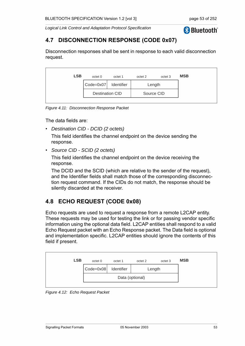
BLUETOOTH SPECIFICATION Version 1.2 [vol 3] page 53 of 252
Logical Link Control and Adaptation Protocol Specification
4.7 DISCONNECTION RESPONSE (CODE 0x07)
Disconnection responses shall be sent in response to each valid disconnection request.
Figure 4.11: Disconnection Response Packet
The data fields are:
• Destination CID - DCID (2 octets)This field identifies the channel endpoint on the device sending the response.
• Source CID - SCID (2 octets)This field identifies the channel endpoint on the device receiving the response.The DCID and the SCID (which are relative to the sender of the request), and the Identifier fields shall match those of the corresponding disconnec-tion request command. If the CIDs do not match, the response should be silently discarded at the receiver.
4.8 ECHO REQUEST (CODE 0x08)
Echo requests are used to request a response from a remote L2CAP entity. These requests may be used for testing the link or for passing vendor specific information using the optional data field. L2CAP entities shall respond to a valid Echo Request packet with an Echo Response packet. The Data field is optional and implementation specific. L2CAP entities should ignore the contents of this field if present.
Figure 4.12: Echo Request Packet
Length
Source CID
Code=0x07 Identifier
LSB MSBoctet 0 octet 1 octet 2 octet 3
Destination CID
LengthCode=0x08 Identifier
LSB MSBoctet 0 octet 1 octet 2 octet 3
Data (optional)
Signalling Packet Formats 05 November 2003 53
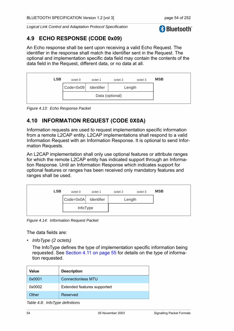
BLUETOOTH SPECIFICATION Version 1.2 [vol 3] page 54 of 252
Logical Link Control and Adaptation Protocol Specification
4.9 ECHO RESPONSE (CODE 0x09)An Echo response shall be sent upon receiving a valid Echo Request. The identifier in the response shall match the identifier sent in the Request. The optional and implementation specific data field may contain the contents of the data field in the Request, different data, or no data at all.
Figure 4.13: Echo Response Packet
4.10 INFORMATION REQUEST (CODE 0X0A) Information requests are used to request implementation specific information from a remote L2CAP entity. L2CAP implementations shall respond to a valid Information Request with an Information Response. It is optional to send Infor-mation Requests.
An L2CAP implementation shall only use optional features or attribute ranges for which the remote L2CAP entity has indicated support through an Informa-tion Response. Until an Information Response which indicates support for optional features or ranges has been received only mandatory features and ranges shall be used.
Figure 4.14: Information Request Packet
The data fields are:
• InfoType (2 octets)The InfoType defines the type of implementation specific information being requested. See Section 4.11 on page 55 for details on the type of informa-tion requested.
Value Description
0x0001 Connectionless MTU
0x0002 Extended features supported
Other Reserved
Table 4.8: InfoType definitions
LengthCode=0x09 Identifier
LSB MSBoctet 0 octet 1 octet 2 octet 3
Data (optional)
LengthCode=0x0A Identifier
LSB MSBoctet 0 octet 1 octet 2 octet 3
InfoType
54 05 November 2003 Signalling Packet Formats

BLUETOOTH SPECIFICATION Version 1.2 [vol 3] page 55 of 252
Logical Link Control and Adaptation Protocol Specification
4.11 INFORMATION RESPONSE (CODE 0X0B)
An information response shall be sent upon receiving a valid Information Request. The identifier in the response shall match the identifier sent in the Request. The data field shall contain the value associated with the InfoType field sent in the Request, or shall be empty if the InfoType is not supported.
Figure 4.15: Information Response Packet
The data fields are:
• InfoType (2 octets)The InfoType defines the type of implementation specific information that was requested. This value shall be copied from the InfoType field in the Information Request.
• Result (2 octets)The Result contains information about the success of the request. If result is "Success", the data field contains the information as specified in Table 4.10 on page 56. If result is "Not supported", no data shall be returned.
• Data (0 or more octets)The contents of the Data field depends on the InfoType. For InfoType = 0x0001 the data field contains the remote entity’s 2-octet acceptable connectionless MTU. The default value is defined in Section 3.2 on page 34. For InfoType = 0x0002, the data field contains the 4 octet L2CAP extended feature mask. The feature mask refers to the extended features that the L2CAP entity sending the Information Response supports. The feature bits contained in the L2CAP feature mask are specified in Section 4.12 on page 56.
Value Description
0x0000 Success
0x0001 Not supported
Other Reserved
Table 4.9: Information Response Result values
Code=0x0B LengthIdentifier
LSB MSBoctet 0 octet 1 octet 2 octet 3
InfoType Result
Data (optional)
Signalling Packet Formats 05 November 2003 55
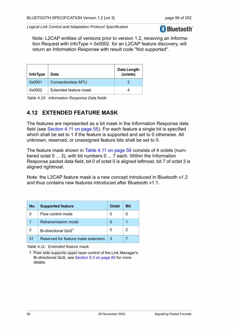
BLUETOOTH SPECIFICATION Version 1.2 [vol 3] page 56 of 252
Logical Link Control and Adaptation Protocol Specification
Note: L2CAP entities of versions prior to version 1.2, receiving an Informa-tion Request with InfoType = 0x0002 for an L2CAP feature discovery, will return an Information Response with result code "Not supported".
4.12 EXTENDED FEATURE MASK
The features are represented as a bit mask in the Information Response data field (see Section 4.11 on page 55). For each feature a single bit is specified which shall be set to 1 if the feature is supported and set to 0 otherwise. All unknown, reserved, or unassigned feature bits shall be set to 0.
The feature mask shown in Table 4.11 on page 56 consists of 4 octets (num-bered octet 0 ... 3), with bit numbers 0 ... 7 each. Within the Information Response packet data field, bit 0 of octet 0 is aligned leftmost, bit 7 of octet 3 is aligned rightmost.
Note: the L2CAP feature mask is a new concept introduced in Bluetooth v1.2 and thus contains new features introduced after Bluetooth v1.1.
InfoType DataData Length
(octets)
0x0001 Connectionless MTU 2
0x0002 Extended feature mask 4
Table 4.10: Information Response Data fields
No. Supported feature Octet Bit
0 Flow control mode 0 0
1 Retransmission mode 0 1
2 Bi-directional QoS1
1. Peer side supports upper layer control of the Link Manager's Bi-directional QoS, see Section 5.3 on page 60 for more details.
0 2
31 Reserved for feature mask extension 3 7
Table 4.11: Extended feature mask.
56 05 November 2003 Signalling Packet Formats

BLUETOOTH SPECIFICATION Version 1.2 [vol 3] page 57 of 252
Logical Link Control and Adaptation Protocol Specification
5 CONFIGURATION PARAMETER OPTIONS
Options are a mechanism to extend the configuration parameters. Options shall be transmitted as information elements containing an option type, an option length, and one or more option data fields. Figure 5.1 illustrates the for-mat of an option.
Figure 5.1: Configuration option format
The configuration option fields are:
• Type (1 octet)The option type field defines the parameters being configured. The most sig-nificant bit of the type determines the action taken if the option is not recog-nized. 0 - option must be recognized; if the option is not recognized then refuse the configuration request1 - option is a hint; if the option is not recognized then skip the option and continue processing
• Length (1 octet)The length field defines the number of octets in the option data. Thus an option type without option data has a length of 0.
• Option dataThe contents of this field are dependent on the option type.
5.1 MAXIMUM TRANSMISSION UNIT (MTU)
This option specifies the maximum SDU size the sender of this option is capa-ble of accepting for a channel. The type is 0x01, and the payload length is 2 octets, carrying the two-octet MTU size value as the only information element (see Figure 5.2 on page 58). Unlike the B-Frame length field, the I-Frame length field may be greater then the configured MTU because it includes the octet lengths of the Control, L2CAP SDU Length (when present), and frame check sequence fields as well as the Information octets.
MTU is not a negotiated value, it is an informational parameter that each device can specify independently. It indicates to the remote device that the local device can receive, in this channel, an MTU larger than the minimum required. All L2CAP implementations shall support a minimum MTU of 48 octets, however some protocols and profiles explicitly require support for a
octet 0 octet 1 octet 2 octet 3
type length option data
LSB MSB
Configuration Parameter Options 05 November 2003 57
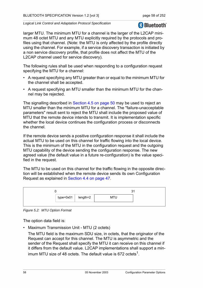
BLUETOOTH SPECIFICATION Version 1.2 [vol 3] page 58 of 252
Logical Link Control and Adaptation Protocol Specification
larger MTU. The minimum MTU for a channel is the larger of the L2CAP mini-mum 48 octet MTU and any MTU explicitly required by the protocols and pro-files using that channel. (Note: the MTU is only affected by the profile directly using the channel. For example, if a service discovery transaction is initiated by a non service discovery profile, that profile does not affect the MTU of the L2CAP channel used for service discovery).
The following rules shall be used when responding to a configuration request specifying the MTU for a channel:
• A request specifying any MTU greater than or equal to the minimum MTU for the channel shall be accepted.
• A request specifying an MTU smaller than the minimum MTU for the chan-nel may be rejected.
The signalling described in Section 4.5 on page 50 may be used to reject an MTU smaller than the minimum MTU for a channel. The "failure-unacceptable parameters" result sent to reject the MTU shall include the proposed value of MTU that the remote device intends to transmit. It is implementation specific whether the local device continues the configuration process or disconnects the channel.
If the remote device sends a positive configuration response it shall include the actual MTU to be used on this channel for traffic flowing into the local device. This is the minimum of the MTU in the configuration request and the outgoing MTU capability of the device sending the configuration response. The new agreed value (the default value in a future re-configuration) is the value speci-fied in the request.
The MTU to be used on this channel for the traffic flowing in the opposite direc-tion will be established when the remote device sends its own Configuration Request as explained in Section 4.4 on page 47.
Figure 5.2: MTU Option Format
The option data field is:
• Maximum Transmission Unit - MTU (2 octets)The MTU field is the maximum SDU size, in octets, that the originator of the Request can accept for this channel. The MTU is asymmetric and the sender of the Request shall specify the MTU it can receive on this channel if it differs from the default value. L2CAP implementations shall support a min-imum MTU size of 48 octets. The default value is 672 octets1.
0 31
type=0x01 length=2 MTU
58 05 November 2003 Configuration Parameter Options
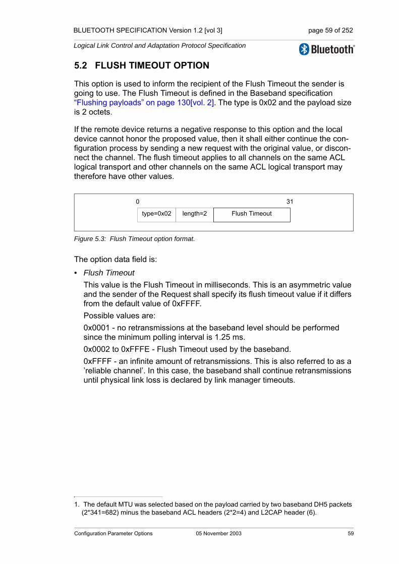
BLUETOOTH SPECIFICATION Version 1.2 [vol 3] page 59 of 252
Logical Link Control and Adaptation Protocol Specification
5.2 FLUSH TIMEOUT OPTION
This option is used to inform the recipient of the Flush Timeout the sender is going to use. The Flush Timeout is defined in the Baseband specification “Flushing payloads” on page 130[vol. 2]. The type is 0x02 and the payload size is 2 octets.
If the remote device returns a negative response to this option and the local device cannot honor the proposed value, then it shall either continue the con-figuration process by sending a new request with the original value, or discon-nect the channel. The flush timeout applies to all channels on the same ACL logical transport and other channels on the same ACL logical transport may therefore have other values.
Figure 5.3: Flush Timeout option format.
The option data field is:
• Flush TimeoutThis value is the Flush Timeout in milliseconds. This is an asymmetric value and the sender of the Request shall specify its flush timeout value if it differs from the default value of 0xFFFF.Possible values are:0x0001 - no retransmissions at the baseband level should be performed since the minimum polling interval is 1.25 ms. 0x0002 to 0xFFFE - Flush Timeout used by the baseband.0xFFFF - an infinite amount of retransmissions. This is also referred to as a ’reliable channel’. In this case, the baseband shall continue retransmissions until physical link loss is declared by link manager timeouts.
1. The default MTU was selected based on the payload carried by two baseband DH5 packets (2*341=682) minus the baseband ACL headers (2*2=4) and L2CAP header (6).
0 31
type=0x02 length=2 Flush Timeout
Configuration Parameter Options 05 November 2003 59
BLUETOOTH SPECIFICATION Version 1.2 [vol 3] page 60 of 252
Logical Link Control and Adaptation Protocol Specification
5.3 QUALITY OF SERVICE (QOS) OPTION
This option specifies a flow specification similar to RFC 13631. Although the RFC flow specification addresses only the transmit characteristics, the Blue-tooth QoS interface can handle the two directions (Tx and Rx) in the negotia-tion as described below.
If no QoS configuration parameter is negotiated the link shall assume the default parameters. The QoS option is type 0x03.
In a configuration request, this option describes the outgoing traffic flow from the device sending the request. In a positive Configuration Response, this option describes the incoming traffic flow agreement to the device sending the response. In a negative Configuration Response, this option describes the pre-ferred incoming traffic flow to the device sending the response.
L2CAP implementations are only required to support ’Best Effort’ service, sup-port for any other service type is optional. Best Effort does not require any guarantees. If no QoS option is placed in the request, Best Effort shall be assumed. If any QoS guarantees are required then a QoS configuration request shall be sent.
The remote device’s Configuration Response contains information that depends on the value of the result field (see Section 4.5 on page 50). If the request was for Guaranteed Service, the response shall include specific values for any wild card parameters (see Token Rate and Token Bucket Size descrip-tions) contained in the request. If the result is “Failure – unacceptable parame-ters”, the response shall include a list of outgoing flow specification parameters and parameter values that would make a new Connection Request from the local device acceptable by the remote device. Both explicitly referenced in a Configuration Request or implied configuration parameters can be included in a Configuration Response. Recall that any missing configuration parameters from a Configuration Request are assumed to have their most recently accepted values.
If a configuration request contains any QoS option parameters set to “do not care” then the configuration response shall set the same parameters to “do not care”. This rule applies for both Best Effort and Guaranteed Service.
1. Internet Engineering Task Force, “A Proposed Flow Specification”, RFC 1363, September 1992.
60 05 November 2003 Configuration Parameter Options

BLUETOOTH SPECIFICATION Version 1.2 [vol 3] page 61 of 252
Logical Link Control and Adaptation Protocol Specification
Figure 5.4: Quality of Service (QoS) option format containing Flow Specification.
The option data fields are:
• Flags (1 octet)Reserved for future use and shall be set to 0 and ignored by the receiver.
• Service Type (1 octet)This field indicates the level of service required. Table 5.1 on page 61 defines the different services available. The default value is ‘Best effort’.If ’Best effort’ is selected, the remaining parameters should be treated as optional by the remote device. The remote device may choose to ignore the fields, try to satisfy the parameters but provide no response (QoS option omitted in the Response message), or respond with the settings it will try to meet.If ’No traffic’ is selected, the remainder of the fields shall be ignored because there is no data being sent across the channel in the outgoing direction.
• Token Rate (4 octets)The value of this field represents the average data rate with which the appli-cation transmits data. The application may send data at this rate continu-ously. On a short time scale the application may send data in excess of the average data rate, dependent on the specified Token Bucket Size and Peak Bandwidth (see below). The Token Bucket Size and Peak Bandwidth allow the application to transmit data in a 'bursty' fashion.
Value Description
0x00 No traffic
0x01 Best effort (Default)
0x02 Guaranteed
Other Reserved
Table 5.1: Service type definitions
Flags service type
Delay Variation (microseconds)
Token Rate
Token Bucket Size (octets)
Peak Bandwidth (octets/second)
Latency (microseconds)
0x03 length=22
310
Configuration Parameter Options 05 November 2003 61
BLUETOOTH SPECIFICATION Version 1.2 [vol 3] page 62 of 252
Logical Link Control and Adaptation Protocol Specification
The Token Rate signalled between two L2CAP peers is the data transmitted by the application and shall exclude the L2CAP protocol overhead. The Token Rate signalled over the interface between L2CAP and the Link Man-ager shall include the L2CAP protocol overhead. Furthermore the Token Rate value signalled over this interface may also include the aggregation of multiple L2CAP channels onto the same ACL logical transport. The Token Rate is the rate with which traffic credits are provided. Credits can be accumulated up to the Token Bucket Size. Traffic credits are con-sumed when data is transmitted by the application. When traffic is transmit-ted, and there are insufficient credits available, the traffic is non-conformant. The Quality of Service guarantees are only provided for conformant traffic. For non-conformant traffic there may not be sufficient resources such as bandwidth and buffer space. Furthermore non-conformant traffic may violate the QoS guarantees of other traffic flows. The Token Rate is specified in octets per second. The value 0x00000000 indicates no token rate is specified. This is the default value and means “do not care”. When the Guaranteed service is selected, the default value shall not be used. The value 0xFFFFFFFF is a wild card matching the maximum token rate available. The meaning of this value depends on the service type. For best effort, the value is a hint that the application wants as much band-width as possible. For Guaranteed service the value represents the maxi-mum bandwidth available at the time of the request.
• Token Bucket Size (4 octets)The Token Bucket Size specifies a limit on the 'burstiness' with which the application may transmit data. The application may offer a burst of data equal to the Token Bucket Size instantaneously, limited by the Peak Band-width (see below). The Token Bucket Size is specified in octets. The Token Bucket Size signalled between two L2CAP peers is the data transmitted by the application and shall exclude the L2CAP protocol over-head. The Token Bucket Size signalled over the interface between L2CAP and Link Manager shall include the L2CAP protocol overhead. Furthermore the Token Bucket Size value over this interface may include the aggregation of multiple L2CAP channels onto the same ACL logical transport.The value of 0x00000000 means that no token bucket is needed; this is the default value. When the Guaranteed service is selected, the default value shall not be used. The value 0xFFFFFFFF is a wild card matching the maxi-mum token bucket available. The meaning of this value depends on the ser-vice type. For best effort, the value indicates the application wants a bucket as big as possible. For Guaranteed service the value represents the maxi-mum L2CAP SDU size. The Token Bucket Size is a property of the traffic carried over the L2CAP channel. The Maximum Transmission Unit (MTU) is a property of an L2CAP implementation. For the Guaranteed service the Token Bucket Size shall be smaller or equal to the MTU.
62 05 November 2003 Configuration Parameter Options
BLUETOOTH SPECIFICATION Version 1.2 [vol 3] page 63 of 252
Logical Link Control and Adaptation Protocol Specification
• Peak Bandwidth (4 octets)The value of this field, expressed in octets per second, limits how fast pack-ets from applications may be sent back-to-back. Some systems can take advantage of this information, resulting in more efficient resource allocation.The Peak Bandwidth signalled between two L2CAP peers specifies the data transmitted by the application and shall exclude the L2CAP protocol over-head. The Peak Bandwidth signalled over the interface between L2CAP and Link Manager shall include the L2CAP protocol overhead. Furthermore the Peak Bandwidth value over this interface may include the aggregation of multiple L2CAP channels onto the same ACL logical transport. The value of 0x00000000 means "don't care". This states that the device has no preference on incoming maximum bandwidth, and is the default value. When the Guaranteed service is selected, the default value shall not be used.
• Access Latency (4 octets)The value of this field is the maximum acceptable delay of an L2CAP packet to the air-interface. The precise interpretation of this number depends on over which interface this flow parameter is signalled. When signalled between two L2CAP peers, the Access Latency is the maximum acceptable delay between the instant when the L2CAP SDU is received from the upper layer and the start of the L2CAP SDU transmission over the air. When sig-nalled over the interface between L2CAP and the Link Manager, it is the maximum delay between the instant the first fragment of an L2CAP PDU is stored in the Host Controller buffer and the initial transmission of the L2CAP packet on the air. Thus the Access Latency value may be different when signalled between L2CAP and the Link Manager to account for any queuing delay at the L2CAP transmit side. Furthermore the Access Latency value may include the aggregation of multiple L2CAP channels onto the same ACL logical transport. The Access Latency is expressed in microseconds. The value 0xFFFFFFFF means “do not care” and is the default value. When the Guaranteed service is selected, the default value shall not be used.
• Delay Variation (4 octets)The value of this field is the difference, in microseconds, between the maxi-mum and minimum possible delay of an L2CAP SDU between two L2CAP peers. The Delay Variation is a purely informational parameter. The value 0xFFFFFFFF means “do not care” and is the default value.
Configuration Parameter Options 05 November 2003 63

BLUETOOTH SPECIFICATION Version 1.2 [vol 3] page 64 of 252
Logical Link Control and Adaptation Protocol Specification
5.4 RETRANSMISSION AND FLOW CONTROL OPTION
This option specifies whether retransmission and flow control is used. If the feature is used incoming parameters are specified by this option.
Figure 5.5: Retransmission and Flow Control option format.
The option data fields are:
• Mode (1 octet) The field contain the requested mode of the link. Possible values are shown in Table 5.2 on page 64.
The Basic L2CAP mode is the default. If Basic L2CAP mode is requested then all other parameters shall be ignored.Retransmission mode should be enabled if a reliable channel has been requested, or if the L2CAP Flush Time-Out is long enough to contain the round-trip delay of a retransmission request.
• TxWindow size (1 octet)This field specifies the size of the transmission window for flow control mode and retransmission mode. The range is 1 to 32. This parameter should be negotiated to reflect the buffer sizes allocated for the connection on both sides. In general, the Tx Window size should be made as large as possible to maximize channel utilization. Tx Window size also controls the delay on flow control action. The transmitting device can send as many PDUs fit within the window.
Value Description
0x00 Basic L2CAP mode
0x01 Retransmission Mode
0x02 Flow control mode
Other values Reserved for future use
Table 5.2: Mode definitions.
0x04
Max Transmit Retransmission time-out
Length=9 Mode TxWindow size
Monitor time-out�(least significant byte)
Monitor time-out�(most significant byte) Maximum PDU size (MPS)
0 31
64 05 November 2003 Configuration Parameter Options

BLUETOOTH SPECIFICATION Version 1.2 [vol 3] page 65 of 252
Logical Link Control and Adaptation Protocol Specification
• MaxTransmit (1 octet)This field controls the number of transmissions of a single I-frame that L2CAP is allowed to try in Retransmission mode. The minimum value is 1 (one transmission is permitted).MaxTransmit controls the number of retransmissions that L2CAP is allowed to try in Retransmission mode before accepting that a packet and the link is lost. Lower values might be appropriate for services requiring low latency. Higher val-ues will be suitable for a link requiring robust operation. A value of 1 means that no retransmissions will be made but also means that the link will be dropped as soon as a packet is lost. MaxTransmit shall not be set to zero.
• Retransmission time-out (2 octets)This is the value in milliseconds of the retransmission time-out (this value is used to initialize the RetransmissionTimer, see below).The purpose of this timer in retransmission mode is to activate a retransmis-sion in some exceptional cases. In such cases, any delay requirements on the channel may be broken, so the value of the timer should be set high enough to avoid unnecessary retransmissions due to delayed acknowledge-ments. Suitable values could be 100’s of milliseconds and up.The purpose of this timer in flow control mode is to supervise I-frame trans-missions. If an acknowledgement for an I-frame is not received within the time specified by the RetransmissionTimer value, either because the I-frame has been lost or the acknowledgement has been lost, the timeout will cause the transmitting side to continue transmissions. Suitable values are imple-mentation dependent.
• Monitor time-out (2 octets)This is the value in milliseconds of the interval at which S-frames should be transmitted on the return channel when no frames are received on the for-ward channel. (this value is used to initialize the MonitorTimer, see below).This timer ensures that lost acknowledgements are retransmitted. Its main use is to recover Retransmission Disable Bit changes in lost frames when no data is being sent. The timer shall be started immediately upon transition-ing to the open state. It shall remain active as long as the connection is in the open state and the retransmission timer is not active. Upon expiration of the Monitor timer an S-frame shall be sent and the timer shall be restarted. If the monitor timer is already active when an S-frame is sent, the timer shall be restarted. An idle connection will have periodic monitor traffic sent in both directions. The value for this time-out should also be set to 100’s of millisec-onds or higher.
• Maximum PDU payload Size - MPS (2 octets)The maximum size of payload data in octets that the L2CAP layer entity is capable of accepting, i.e. the MPS corresponds to the maximum PDU pay-load size.
The settings are configured separately for the two directions of an L2CAP con-nection. For example, an L2CAP connection can be configured as Flow Control
Configuration Parameter Options 05 November 2003 65
BLUETOOTH SPECIFICATION Version 1.2 [vol 3] page 66 of 252
Logical Link Control and Adaptation Protocol Specification
mode in one direction and Retransmission mode in the other direction. If Basic L2CAP mode is configured in one direction and Retransmission mode or Flow control mode is configured in the other direction on the same L2CAP channel then the channel shall not be used. Note: this asymmetric configuration only occurs during configuration.
66 05 November 2003 Configuration Parameter Options
BLUETOOTH SPECIFICATION Version 1.2 [vol 3] page 67 of 252
Logical Link Control and Adaptation Protocol Specification
6 STATE MACHINE
This section is informative. The state machine may not represent all possible scenarios.
6.1 GENERAL RULES FOR THE STATE MACHINE:• It is implementation specific, and outside the scope of this specification, how
the transmissions are triggered. • "Ignore" means that the signal can be silently discarded.
The following states have been defined to clarify the protocol; the actual num-ber of states and naming in a given implementation is outside the scope of this specification:• CLOSED – channel not connected.• WAIT_CONNECT – a connection request has been received, but only a
connection response with indication “pending” can be sent.• WAIT_CONNECT_RSP – a connection request has been sent, pending a
positive connect response.• CONFIG – the different options are being negotiated for both sides; this
state comprises a number of substates, see Section 6.1.3 on page 69• OPEN – user data transfer state.• WAIT_DISCONNECT – a disconnect request has been sent, pending a dis-
connect response.
Below the L2CAP_Data message corresponds to one of the PDU formats used on connection-oriented data channels as described in section 3, including PDUs containing B-frames, I-frames, S-frames.
Some state transitions and actions are triggered only by internal events effect-ing one of the L2CAP entity implementations, not by preceding L2CAP signal-ling messages. It is implementation-specific and out of the scope of this specification, how these internal events are realized; just for the clarity of spec-ifying the state machine, the following abstract internal events are used in the state event tables, as far as needed:• OpenChannel_Req – a local L2CAP entity is requested to set up a new con-
nection-oriented channel.• OpenChannel_Rsp – a local L2CAP entity is requested to finally accept or
refuse a pending connection request.• ConfigureChannel_Req – a local L2CAP entity is requested to initiate an
outgoing configuration request.• CloseChannel_Req – a local L2CAP entity is requested to close a channel.• SendData_Req – a local L2CAP entity is requested to transmit an SDU.• ReconfigureChannel_Req – a local L2CAP entity is requested to reconfigure
the parameters of a connection-oriented channel.
State Machine 05 November 2003 67

BLUETOOTH SPECIFICATION Version 1.2 [vol 3] page 68 of 252
Logical Link Control and Adaptation Protocol Specification
There is a single state machine for each L2CAP connection-oriented channel that is active. A state machine is created for each new L2CAP_ConnectReq received. The state machine always starts in the CLOSED state.
To simplify the state event tables, the RTX and ERTX timers, as well as the handling of request retransmissions are described in Section 6.2 on page 74 and not included in the state tables.
L2CAP messages not bound to a specific data channel and thus not impacting a channel state (e.g. L2CAP_InformationReq, L2CAP_EchoReq) are not cov-ered in this section.
The following states and transitions are illustrated in Figure 6.1 on page 76.
6.1.1 CLOSED state
Notes: - The L2CAP_ConnectReq message is not mentioned in any of the other states apart
from the CLOSED state, as it triggers the establishment of a new channel, thus the branch into a new instance of the state machine.
Event Condition Action Next State
OpenChannel_req - Send L2CAP_ConnectReq
WAIT_CONNECT_RSP
L2CAP_ConnectReq Normal, connec-tion is possible
Send L2CAP_ConnectRsp (success)
CONFIG (substate WAIT_CONFIG)
L2CAP_ConnectReq Need to indicate pending
Send L2CAP_ConnectRsp (pending)
WAIT_CONNECT
L2CAP_ConnectReqNo resource, not approved, etc
Send L2CAP_ConnectRsp (refused)
CLOSED
L2CAP_ConnectRsp - Ignore CLOSED
L2CAP_ConfigReq -
Send L2CAP_CommandReject (with reason Invalid CID)
CLOSED
L2CAP_ConfigRsp - Ignore CLOSED
L2CAP_DisconnectReq - Send L2CAP_DisconnectRsp CLOSED
L2CAP_DisconnectRsp - Ignore CLOSED
L2CAP_Data - Ignore CLOSED
Table 6.1: CLOSED state event table.
68 05 November 2003 State Machine
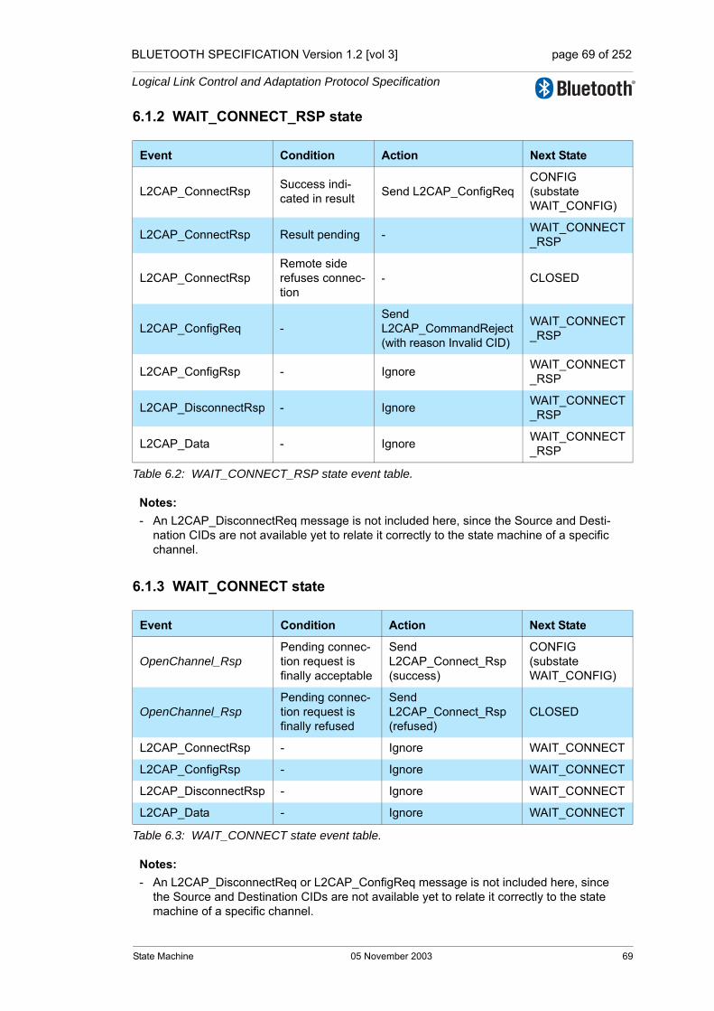
BLUETOOTH SPECIFICATION Version 1.2 [vol 3] page 69 of 252
Logical Link Control and Adaptation Protocol Specification
6.1.2 WAIT_CONNECT_RSP state
Notes:- An L2CAP_DisconnectReq message is not included here, since the Source and Desti-
nation CIDs are not available yet to relate it correctly to the state machine of a specific channel.
6.1.3 WAIT_CONNECT state
Notes:- An L2CAP_DisconnectReq or L2CAP_ConfigReq message is not included here, since
the Source and Destination CIDs are not available yet to relate it correctly to the state machine of a specific channel.
Event Condition Action Next State
L2CAP_ConnectRsp Success indi-cated in result Send L2CAP_ConfigReq
CONFIG (substate WAIT_CONFIG)
L2CAP_ConnectRsp Result pending - WAIT_CONNECT_RSP
L2CAP_ConnectRspRemote side refuses connec-tion
- CLOSED
L2CAP_ConfigReq -Send L2CAP_CommandReject (with reason Invalid CID)
WAIT_CONNECT_RSP
L2CAP_ConfigRsp - Ignore WAIT_CONNECT_RSP
L2CAP_DisconnectRsp - Ignore WAIT_CONNECT_RSP
L2CAP_Data - Ignore WAIT_CONNECT_RSP
Table 6.2: WAIT_CONNECT_RSP state event table.
Event Condition Action Next State
OpenChannel_RspPending connec-tion request is finally acceptable
Send L2CAP_Connect_Rsp (success)
CONFIG (substate WAIT_CONFIG)
OpenChannel_RspPending connec-tion request is finally refused
Send L2CAP_Connect_Rsp (refused)
CLOSED
L2CAP_ConnectRsp - Ignore WAIT_CONNECT
L2CAP_ConfigRsp - Ignore WAIT_CONNECT
L2CAP_DisconnectRsp - Ignore WAIT_CONNECT
L2CAP_Data - Ignore WAIT_CONNECT
Table 6.3: WAIT_CONNECT state event table.
State Machine 05 November 2003 69

BLUETOOTH SPECIFICATION Version 1.2 [vol 3] page 70 of 252
Logical Link Control and Adaptation Protocol Specification
6.1.4 CONFIG state
As it is also described in Section 7.1 on page 79, both L2CAP entities initiate a configuration request during the configuration process. This means that each device adopts an initiator role for the outgoing configuration request, and an acceptor role for the incoming configuration request. Configurations in both directions may occur sequentially, but can also occur in parallel.
The following substates are distinguished within the CONFIG state:• WAIT_CONFIG – a device has sent or received a connection response, but
has neither initiated a configuration request yet, nor received a configuration request with acceptable parameters.
• WAIT_SEND_CONFIG – for the initiator path, a configuration request has not yet been initiated, while for the response path, a request with acceptable options has been received.
• WAIT_CONFIG_REQ_RSP – for the initiator path, a request has been sent but a positive response has not yet been received, and for the acceptor path, a request with acceptable options has not yet been received.
• WAIT_CONFIG_RSP – the acceptor path is complete after having responded to acceptable options, but for the initiator path, a positive response on the recent request has not yet been received.
• WAIT_CONFIG_REQ – the initiator path is complete after having received a positive response, but for the acceptor path, a request with acceptable options has not yet been received.
According to Section 6.1.1 on page 68 and Section 6.1.2 on page 69, the CON-FIG state is entered via WAIT_CONFIG substate from either the CLOSED state, the WAIT_CONNECT state, or the WAIT_CONNECT_RSP state. The CONFIG state is left for the OPEN state if both the initiator and acceptor paths complete successfully.
For better overview, separate tables are given: Table 6.4 shows the success transitions; therein, transitions on one of the minimum paths (no previous non-success transitions) are shaded. Table 6.5 on page 71 shows the non-success transitions within the configuration process, and Table 6.6 on page 72 shows fur-ther transition cause by events not belonging to the configuration process itself.The following configurtion states and transitions are illustrated in Figure 6.2 on page 77.
Previous state Event Condition Action Next State
WAIT_CONFIG ConfigureChannel_Req -
Send L2CAP_ConfigReq
WAIT_CONFIG_REQ_RSP
WAIT_CONFIG L2CAP_ConfigReq Options acceptable
Send L2CAP_ConfigRsp (success)
WAIT_SEND_CONFIG
Table 6.4: CONFIG state/substates event table: success transitions within configuration process.
70 05 November 2003 State Machine
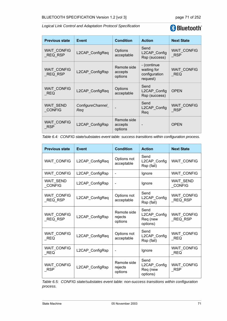
BLUETOOTH SPECIFICATION Version 1.2 [vol 3] page 71 of 252
Logical Link Control and Adaptation Protocol Specification
WAIT_CONFIG_REQ_RSP L2CAP_ConfigReq Options
acceptable
Send L2CAP_ConfigRsp (success)
WAIT_CONFIG_RSP
WAIT_CONFIG_REQ_RSP L2CAP_ConfigRsp
Remote side accepts options
- (continue waiting for configuration request)
WAIT_CONFIG_REQ
WAIT_CONFIG_REQ L2CAP_ConfigReq Options
acceptable
Send L2CAP_ConfigRsp (success)
OPEN
WAIT_SEND_CONFIG
ConfigureChannel_Req -
Send L2CAP_ConfigReq
WAIT_CONFIG_RSP
WAIT_CONFIG_RSP L2CAP_ConfigRsp
Remote side accepts options
- OPEN
Previous state Event Condition Action Next State
WAIT_CONFIG L2CAP_ConfigReq Options not acceptable
Send L2CAP_ConfigRsp (fail)
WAIT_CONFIG
WAIT_CONFIG L2CAP_ConfigRsp - Ignore WAIT_CONFIG
WAIT_SEND_CONFIG L2CAP_ConfigRsp - Ignore WAIT_SEND
_CONFIG
WAIT_CONFIG_REQ_RSP L2CAP_ConfigReq Options not
acceptable
Send L2CAP_ConfigRsp (fail)
WAIT_CONFIG_REQ_RSP
WAIT_CONFIG_REQ_RSP L2CAP_ConfigRsp
Remote side rejects options
Send L2CAP_ConfigReq (new options)
WAIT_CONFIG_REQ_RSP
WAIT_CONFIG_REQ L2CAP_ConfigReq Options not
acceptable
Send L2CAP_ConfigRsp (fail)
WAIT_CONFIG_REQ
WAIT_CONFIG_REQ L2CAP_ConfigRsp - Ignore WAIT_CONFIG
_REQ
WAIT_CONFIG_RSP L2CAP_ConfigRsp
Remote side rejects options
Send L2CAP_ConfigReq (new options)
WAIT_CONFIG_RSP
Table 6.5: CONFIG state/substates event table: non-success transitions within configuration process.
Previous state Event Condition Action Next State
Table 6.4: CONFIG state/substates event table: success transitions within configuration process.
State Machine 05 November 2003 71

BLUETOOTH SPECIFICATION Version 1.2 [vol 3] page 72 of 252
Logical Link Control and Adaptation Protocol Specification
Notes:- Receiving data PDUs (L2CAP_Data) in CONFIG state should be relevant only in case
of a transition to a reconfiguration procedure (from OPEN state). Discarding the received data is allowed only in Retransmission Mode. Discarding an S-frame is allowed but not recommended. If a S-frame is discarded, the monitor timer will cause a new S-frame to be sent after a time out.
- Indicating a failure in a configuration response does not necessarily imply a failure of the overall configuration procedure; instead, based on the information received in the negative response, a modified configuration request may be triggered.
Previous state Event Condition Action Next State
CONFIG(any substate) CloseChannel_Req
Any internal reason to stop
Send L2CAP_DisconnectReq
WAIT_DISCONNECT
CONFIG(any substate)
L2CAP_DisconnectReq -
Send L2CAP_DisconnectRsp
CLOSED
CONFIG(any substate)
L2CAP_DisconnectRsp - Ignore
CONFIG (remain in sub-state)
CONFIG(any substate) L2CAP_Data - Process the
PDU
CONFIG (remain in sub-state)
Table 6.6: CONFIG state/substates event table: events not related to configuration process.
72 05 November 2003 State Machine

BLUETOOTH SPECIFICATION Version 1.2 [vol 3] page 73 of 252
Logical Link Control and Adaptation Protocol Specification
6.1.5 OPEN state
6.1.6 WAIT_DISCONNECT state
Event Condition Action Next State
SendData_req -Send L2CAP_Data packet according to con-figured mode
OPEN
ReconfigureChannel_req -
Complete outgoing SDUSend L2CAP_ConfigReq
CONFIG (sub-state WAIT_CONFIG_RSP)
CloseChannel_req - Send L2CAP_DisconnectReq
WAIT_DISCONNECT
L2CAP_ConnectRsp - Ignore OPEN
L2CAP_ConfigReqIncoming config. options accept-able
Complete outgoing SDU Send L2CAP_ConfigRsp (ok)
CONFIG (substateWAIT_CONFIG_REQ)
L2CAP_ConfigReqIncoming config. options not acceptable
Complete outgoing SDUSend L2CAP_ConfigRsp (fail)
OPEN
L2CAP_DisconnectReq - Send L2CAP_DisconnectRsp CLOSED
L2CAP_DisconnectRsp - Ignore OPEN
L2CAP_Data - Process the PDU OPEN
Table 6.7: OPEN state event table.
Event Condition Action Next State
L2CAP_ConnectRsp - Ignore WAIT_DISCONNECT
L2CAP_ConfigReq -Send L2CAP_CommandRejectwith reason Invalid CID
WAIT_DISCONNECT
L2CAP_ConfigRsp - Ignore WAIT_DISCONNECT
L2CAP_DisconnectReq - Send L2CAP_DisconnectRsp CLOSED
L2CAP_DisconnectRsp - - CLOSED
L2CAP_Data - Ignore WAIT_DISCONNECT
Table 6.8: WAIT_DISCONNECT state event table.
State Machine 05 November 2003 73

BLUETOOTH SPECIFICATION Version 1.2 [vol 3] page 74 of 252
Logical Link Control and Adaptation Protocol Specification
6.2 TIMERS EVENTS
6.2.1 RTX
The Response Timeout eXpired (RTX) timer is used to terminate the channel when the remote endpoint is unresponsive to signalling requests. This timer is started when a signalling request (see Section 7 on page 79) is sent to the remote device. This timer is disabled when the response is received. If the ini-tial timer expires, a duplicate Request message may be sent or the channel identified in the request may be disconnected. If a duplicate Request message is sent, the RTX timeout value shall be reset to a new value at least double the previous value. When retransmitting the Request message, the context of the same state shall be assumed as with the original transmission. If a Request message is received that is identified as a duplicate (retransmission), it shall (should??) be processed in the context of the same state which applied when the original Request message was received.
Implementations have the responsibility to decide on the maximum number of Request retransmissions performed at the L2CAP level before terminating the channel identified by the Requests. The one exception is the signalling CID that should never be terminated. The decision should be based on the flush timeout of the signalling link. The longer the flush timeout, the more retransmis-sions may be performed at the physical layer and the reliability of the channel improves, requiring fewer retransmissions at the L2CAP level.
For example, if the flush timeout is infinite, no retransmissions should be per-formed at the L2CAP level. When terminating the channel, it is not necessary to send a L2CAP_DisconnectReq and enter WAIT_DISCONNECT state. Channels can be transitioned directly to the CLOSED state.
The value of this timer is implementation-dependent but the minimum initial value is 1 second and the maximum initial value is 60 seconds. One RTX timer shall exist for each outstanding signalling request, including each Echo Request. The timer disappears on the final expiration, when the response is received, or the physical link is lost. The maximum elapsed time between the initial start of this timer and the initiation of channel termination (if no response is received) is 60 seconds.
74 05 November 2003 State Machine
BLUETOOTH SPECIFICATION Version 1.2 [vol 3] page 75 of 252
Logical Link Control and Adaptation Protocol Specification
6.2.2 ERTX
The Extended Response Timeout eXpired (ERTX) timer is used in place of the RTX timer when it is suspected the remote endpoint is performing additional processing of a request signal. This timer is started when the remote endpoint responds that a request is pending, e.g., when an L2CAP_ConnectRsp event with a "connect pending" result (0x0001) is received. This timer is disabled when the formal response is received or the physical link is lost. If the initial timer expires, a duplicate Request may be sent or the channel may be discon-nected.
If a duplicate Request is sent, the particular ERTX timer disappears, replaced by a new RTX timer and the whole timing procedure restarts as described pre-viously for the RTX timer.
The value of this timer is implementation-dependent but the minimum initial value is 60 seconds and the maximum initial value is 300 seconds. Similar to RTX, there MUST be at least one ERTX timer for each outstanding request that received a Pending response. There should be at most one (RTX or ERTX) associated with each outstanding request. The maximum elapsed time between the initial start of this timer and the initiation of channel termination (if no response is received) is 300 seconds. When terminating the channel, it is not necessary to send a L2CAP_DisconnectReq and enter WAIT_DISCONNECT state. Channels should be transitioned directly to the CLOSED state.
State Machine 05 November 2003 75

BLUETOOTH SPECIFICATION Version 1.2 [vol 3] page 76 of 252
Logical Link Control and Adaptation Protocol Specification
Figure 6.1: States and transitions.
Ev ent: L2CAP_DisconnectReqAction: L2CAP_DisconnectRsp
Ev ent: L2CAP_DisconnectRspAction: -
Ev ent: L2CAP_DisconnectReqAction: L2CAP_DisconnectRsp
Ev ent: CloseChannelReqAction: L2CAP_DisconnectReq
Ev ent: L2CAP_Conf igReqAction: L2CAP_Conf igRsp
Ev ent: L2CAP_Conf igReqAction: L2CAP_CommandReject (inv alid CID)
Ev ent: L2CAP_ConnectRsp OR L2CAP_Conf igReq OR L2CAP_DataAction: Ignore
Ev ent: Reconf igureChannelReqAction: Complete outgoing SDU L2CAP_Conf igReq
Ev ent: L2CAP_Conf igReq options acceptableAction: L2CAP_Conf igRsp(success)
Ev ent: L2CAP_Conf igReq options not acceptableAction: L2CAP_Conf igRsp (f ail)
Ev ent: CloseChannelReqAction: L2CAP_DisconnectReq
CLOSED
Ev ent: SendDataReqAction: Send L2CAP_Data packet
Ev ent: L2CAP_DataAction: Process the PDU
Ev ent: L2CAP_DisconnectRsp OR L2CAP_ConnectRspAction: Ignore
Ev ent: L2CAP_ConnectRsp (success)Action: -
Ev ent: OpenChannelReqAction: L2CAP_ConnectReq
Ev ent: L2CAP_ConnectReqAction: L2CAP_ConnectRsp (pending)
Ev ent: OpenChannelRes (success)Action: L2CAP_ConnectRsp (success)
Ev ent: L2CAP_DataAction: process the PDU
Ev ent: L2CAP_ConnectReqAction: L2CAP_ConnectRsp (success)
Ev ent: L2CAP_ConnectionRsp (ref used)Action: -
Ev ent: L2CAP_ConnectionRsp (ref used)Action: -
Ev ent: L2CAP_DisconnectReqAction: L2CAP_DisconnectRsp
CLOSED
OPEN
WAIT_DIS-�CONNECT CONFIG
WAIT_CONNECT_
RSP
WAIT_CONNECT
76 05 November 2003 State Machine

BLUETOOTH SPECIFICATION Version 1.2 [vol 3] page 77 of 252
Logical Link Control and Adaptation Protocol Specification
Figure 6.2: Configuration states and transitions.
WAIT_SEND_CONFIG
WAIT_CONFIG_REQ_RSP
WAIT_CONFIG_
RSP
WAIT_CONFIG_
REQ
OPEN
Ev ent: L2CAP_Conf igReq options not acceptableAction: L2CAP_Conf igRsp (f ail)
Ev ent: ConfigureChannelReqAction: L2CAP_Conf igReq
WAIT_CONNECT
WAIT_CONNECT_
RSP
Ev ent: L2CAP_ConnectRsp (success)
Ev ent: L2CAP_ConnectReqAction: L2CAP_ConnectRsp (success)
Ev ent: OpenChannel_Rsp (success)Action: L2CAP_ConnectRsp (success)
Ev ent: L2CAP_Conf igReq options not acceptableAction: L2CAP_Conf igRsp (f ail)
Ev ent: L2CAP_Conf igReq options not acceptableAction: L2CAP_Conf igRsp (f ail)
Ev ent: L2CAP_Conf igReq options acceptableAction: L2CAP_Conf igRsp (success)
Ev ent: ConfigureChannelReqAction: L2CAP_Conf igReq
Ev ent: L2CAP_Conf igRsp (f ail)Action: L2CAP_Conf igReq (new options)
Ev ent: L2CAP_Conf igReq options acceptableAction: L2CAP_Conf igRsp (success)
Ev ent: L2CAP_Conf igRsp options acceptable
Ev ent: L2CAP_Conf igRsp options acceptable
Ev ent: L2CAP_Conf igRsp (f ail)Action: L2CAP_Conf igReq (new options)
Ev ent: L2CAP_Conf igReq options acceptableAction: L2CAP_Conf igRsp (success)
CLOSED
WAIT_CONFIG
State Machine 05 November 2003 77

BLUETOOTH SPECIFICATION Version 1.2 [vol 3] page 78 of 252
Logical Link Control and Adaptation Protocol Specification
78 05 November 2003 State Machine
BLUETOOTH SPECIFICATION Version 1.2 [vol 3] page 79 of 252
Logical Link Control and Adaptation Protocol Specification
7 GENERAL PROCEDURES
This section describes the general operation of L2CAP, including the configura-tion process, the handling and the processing of user data for transportation over the air interface. This section also describes the operation of L2CAP fea-tures including the delivery of erroneous packets, the flushing of expired data and operation in connectionless mode.
Procedures for the flow control and retransmission modes are described in Section 8 on page 87.
7.1 CONFIGURATION PROCESS
Configuring the channel parameters shall be done independently for both directions. Both configurations may be done in parallel. For each direction the following procedure shall be used:
1. Informing the remote side of the non-default parameters that the local side will accept using a Configuration Request
2. Remote side responds, agreeing or disagreeing with these values, including the default ones, using a Configuration Response.
3. The local and remote devices repeat steps (1) and (2) until agreement on all parameters is reached.
This process can be abstracted into the initial Request configuration path and a Response configuration path, followed by the reverse direction phase. Reconfigu-ration follows a similar two-phase process by requiring configuration in both direc-tions.
The decision on the amount of time (or messages) spent configuring the chan-nel parameters before terminating the configuration is left to the implementa-tion, but it shall not last more than 120 seconds.
General Procedures 05 November 2003 79

BLUETOOTH SPECIFICATION Version 1.2 [vol 3] page 80 of 252
Logical Link Control and Adaptation Protocol Specification
7.1.1 Request path
The Request Path can configure the following:
• requester’s incoming MTU.
• requester’s outgoing flush timeout.
• requester’s outgoing QoS.
• requester’s incoming flow and error control information.
Table 7.1 on page 80 defines the configuration options that may be placed in a Configuration Request.
The state machine for the configuration process is described in Section 6 on page 67.
7.1.2 Response path
The Response Path can configure the following:
• responder’s outgoing MTU, that is the remote side’s incoming MTU.
• remote side’s flush timeout.
• responder’s incoming QoS Flow Specification (remote side’s outgoing QoS Flow Specification).
• responder’s Outgoing Flow and Error Control information
If a request-oriented parameter is not present in the Request message (reverts to last agreed value), the remote side may negotiate for a non-default value by including the proposed value in a negative Response message.
Parameter Description
MTU Incoming MTU information
FlushTO Outgoing flush timeout
QoS Outgoing QoS information
RFCMode Incoming Retransmission and Flow Control Mode
Table 7.1: Parameters allowed in Request
Parameter Description
MTU Outgoing MTU information
FlushTO Incoming flush timeout
QoS Incoming QoS information
RFCMode Outgoing Retransmission and Flow Control Mode
Table 7.2: Parameters allowed in Response
80 05 November 2003 General Procedures

BLUETOOTH SPECIFICATION Version 1.2 [vol 3] page 81 of 252
Logical Link Control and Adaptation Protocol Specification
7.2 FRAGMENTATION AND RECOMBINATION
Fragmentation is the breaking down of PDUs into smaller pieces for delivery from L2CAP to the lower layer. Recombination is the process of reassembling a PDU from fragments delivered up from the lower layer. Fragmentation and Recombination may be applied to any L2CAP PDUs.
7.2.1 Fragmentation of L2CAP PDUs
An L2CAP implementation may fragment any L2CAP PDU for delivery to the lower layers. If L2CAP runs directly over the link controller protocol, then an implementation may fragment the PDU into multiple baseband packets for transmission over the air. If L2CAP runs above the host controller interface, then an implementation may send HCI transport sized fragments to the Con-troller which passes them to the baseband. All L2CAP fragments associated with an L2CAP PDU shall be passed to the baseband before any other L2CAP PDU for the same logical transport shall be sent.
The two LLID bits defined in the first octet of baseband payload (also called the frame header) are used to signal the start and continuation of L2CAP PDUs. LLID shall be ’10’ for the first segment in an L2CAP PDU and ’01’ for a continu-ation segment. An illustration of fragmentation is shown in Figure 7.1 on page 81. An example of how fragmentation might be used in a device with HCI is shown in Figure 7.2 on page 82.
Figure 7.1: L2CAP fragmentation.
Note: The link controller is able to impose a different fragmentation on the PDU by using "start" and "continuation" indications as fragments are translated into baseband packets. Thus, both L2CAP and the link controller use the same mechanism to control the size of fragments.
PayloadLength
LLID=10 LLID=01 LLID=01
CID
General Procedures 05 November 2003 81
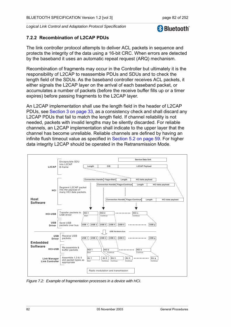
BLUETOOTH SPECIFICATION Version 1.2 [vol 3] page 82 of 252
Logical Link Control and Adaptation Protocol Specification
7.2.2 Recombination of L2CAP PDUs
The link controller protocol attempts to deliver ACL packets in sequence and protects the integrity of the data using a 16-bit CRC. When errors are detected by the baseband it uses an automatic repeat request (ARQ) mechanism.
Recombination of fragments may occur in the Controller but ultimately it is the responsibility of L2CAP to reassemble PDUs and SDUs and to check the length field of the SDUs. As the baseband controller receives ACL packets, it either signals the L2CAP layer on the arrival of each baseband packet, or accumulates a number of packets (before the receive buffer fills up or a timer expires) before passing fragments to the L2CAP layer.
An L2CAP implementation shall use the length field in the header of L2CAP PDUs, see Section 3 on page 33, as a consistency check and shall discard any L2CAP PDUs that fail to match the length field. If channel reliability is not needed, packets with invalid lengths may be silently discarded. For reliable channels, an L2CAP implementation shall indicate to the upper layer that the channel has become unreliable. Reliable channels are defined by having an infinite flush timeout value as specified in Section 5.2 on page 59. For higher data integrity L2CAP should be operated in the Retransmission Mode.
Figure 7.2: Example of fragmentation processes in a device with HCI.
L2CAP PayloadL2CAP
Encapsulate SDU into L2CAP B-frame
HCI-USB
HostSoftware
CID
HCI data payloadFlags=StartConnection Handle Length
HCI data payloadFlags=Continue
HCI data payloadFlags=Continue
Radio modulation and transmission
Segment L2CAP packetinto the payload ofmany HCI data packets.
Transfer packets toUSB driver
USBDriver USB 1 USB 2 USB 3 USB 4 USB 5 USB p
Send USBpackets over bus
USB Hardware bus
USBDriver USB 1 USB 2 USB 3 USB 4 USB 5 USB p
Receive USBpackets.
EmbeddedSoftware
HCI nHCI 2HCI 1Re-assemble &buffer packetsHCI-USB
Air 1 Air 2 Air 3 Air 4 Air qAssemble 1,3 & 5slot packet types asappropriate
Link ManagerLink Controller Continue Continue Continue Continue
Continue ContinueStart
Start
HCI nHCI 2HCI 1Continue ContinueStart
HCI
Length
Length
Connection Handle
Connection Handle
Length
Service Data Unit
82 05 November 2003 General Procedures

BLUETOOTH SPECIFICATION Version 1.2 [vol 3] page 83 of 252
Logical Link Control and Adaptation Protocol Specification
7.3 ENCAPSULATION OF SDUs
All SDUs are encapsulated into one or more L2CAP PDUs.
In Basic L2CAP mode, an SDU shall be encapsulated with a minimum of L2CAP protocol elements, resulting in a type of L2CAP PDU called a Basic Information Frame (B-frame).
Segmentation and Reassembly operations are only used in Retransmission mode and Flow Control mode. SDUs may be segmented into a number of smaller packets called SDU segments. Each segment shall be encapsulated with L2CAP protocol elements resulting in an L2CAP PDU called an Informa-tion Frame (I-frame).
The maximum size of an SDU segment shall be given by the Maximum PDU Payload Size (MPS). The MPS parameter may be exported using an imple-mentation specific interface to the upper layer.
Note that this specification does not have a normative service interface with the upper layer, nor does it assume any specific buffer management scheme of a host implementation. Consequently, a reassembly buffer may be part of the upper layer entity. It is assumed that SDU bounderies shall be preserved between peer upper layer entities.
7.3.1 Segmentation of L2CAP SDUs
In Flow Control or Retransmission modes, incoming SDUs may be broken down into segments, which shall then be individually encapsulated with L2CAP protocol elements (header and checksum fields) to form I-frames. I-frames are subject to flow control and may be subject to retransmission procedures. The header carries a 2 bit SAR field that is used to identify whether the I-frame is a 'start', 'end' or 'continuation' packet or whether it carries a complete, unseg-mented SDU. Figure 7.3 on page 83 illustrates segmentation and fragmentation.
Figure 7.3: Segmentation and fragmentation of an SDU.
L2CAP SDU
I-frame
Fragment/
BB payload
Fragment/
BB payload
HCI
I-frame
Fragment/
BB payload
Fragment/
BB payload
General Procedures 05 November 2003 83

BLUETOOTH SPECIFICATION Version 1.2 [vol 3] page 84 of 252
Logical Link Control and Adaptation Protocol Specification
7.3.2 Reassembly of L2CAP SDUs
The receiving side uses the SAR field of incoming 'I-frames' for the reassembly process. The L2CAP SDU length field, present in the "start of SDU" I-frame, is an extra integrity check, and together with the sequence numbers may be used to indicate lost L2CAP SDUs to the application. Figure 7.3 on page 83 illus-trates segmentation and fragmentation.
7.3.3 Segmentation and fragmentation
Figure 7.4 on page 84 illustrates the use of segmentation and fragmentation operations to transmit a single SDU. Note that while SDUs and L2CAP PDUs are transported in peer-to-peer fashion, the fragment size used by the Frag-mentation and Recombination routines is implementation specific and may not be the same in the sender and the receiver. The over-the-air sequence of baseband packets as created by the sender is common to both devices.
Figure 7.4: Example of segmentation and fragment processes in a device with HCI1
1. For simplicity, the stripping of any additional HCI and USB specific information fields prior to the creation of the baseband packets (Air_1, Air_2, etc.) is not shown in the figure.
L2
CA
P
Segment SDU intothe payload of manyL2CAP I-frames
HCI-USB
Radio modulation and transmission
Fragment L2CAP PDUinto the payload ofmultiple HCI data packets.
Transfer packets toUSB driver
USBDriver USB 1 USB 2 USB 3 USB 4 USB 5 USB p
Send USBpackets over bus
USB Hardware bus
USBDriver USB 1 USB 2 USB 3 USB 4 USB 5 USB p
Receive USBpackets.
HCI nHCI 2HCI 1Re-assemble &buffer packetsHCI-USB
Air 1 Air 2 Air 3 Air 4 Air qAssemble 1,3 & 5slot packet types asappropriate
Link ManagerLink Controller Continue Continue Continue Continue
Continue ContinueStart
Start
HCI nHCI 2HCI 1
Continue ContinueStart
HCI
Length Channel ID Information payloadControl FCSSDU length
Length Channel ID Information payloadControl FCS
Length Channel ID Information payloadControl FCS
Service Data Unit
Connection handle HCI data payloadFlags=continue Length
Connection handle HCI data payloadFlags=start Length
HCI data payloadFlags=continue LengthConnection handle HCI data payloadFlags=continue Length
Host Software
EmbeddedSoftware
84 05 November 2003 General Procedures

BLUETOOTH SPECIFICATION Version 1.2 [vol 3] page 85 of 252
Logical Link Control and Adaptation Protocol Specification
7.4 DELIVERY OF ERRONEOUS L2CAP SDUS
Some applications may require corrupted or incomplete L2CAP SDUs to be delivered to the upper layer. If delivery of erroneous L2CAP SDUs is enabled, the receiving side will pass information to the upper layer on which parts of the L2CAP SDU (i.e., which L2CAP frames) have been lost, failed the error check, or passed the error check. If delivery of erroneous L2CAP SDUs is disabled, the receiver shall discard any L2CAP SDU segment with any missing frames or any frames failing the error checks. L2CAP SDUs whose length field does not match the actual frame length shall also be discarded.
7.5 OPERATION WITH FLUSHING
In the L2CAP configuration, the Flush Time-Out may be set separately per L2CAP channel, but there is only one flush mechanism per ACL logical trans-port in the baseband.
When there is more than one L2CAP channel mapped to the same ACL logical transport, the automatic flush time-out does not discriminate between L2CAP channels. The automatic flush time-out flushes a specific L2CAP PDU. The HCI Flush command flushes all outstanding L2CAP PDUs for the ACL logical transport. Therefore, care has to be taken when using the Automatic Flush Time-out and the HCI Flush command:
1. For any connection to be reliable at the L2CAP level, it should use L2CAP retransmission mode if it is mapped to an ACL logical transport with a finite automatic flush time-out. In retransmission mode, loss of flushed L2CAP PDUs on the channel is detected by the L2CAP ARQ mechanism and they are retransmitted.
2. There is only one automatic flush time-out setting per ACL logical transport. Therefore, all time bounded L2CAP channels on an ACL logical transport with a flush time-out setting should configure the same flush time-out value at the L2CAP level.
3. If Automatic Flush Time-out is used, then it should be taken into account that it only flushes one L2CAP PDU. If one PDU has timed out and needs flush-ing, then others on the same logical transport are also likely to need flush-ing. Therefore, when retransmission mode is used, flushing should be handled by the HCI Flush command so that all outstanding L2CAP PDUs are flushed.
General Procedures 05 November 2003 85
BLUETOOTH SPECIFICATION Version 1.2 [vol 3] page 86 of 252
Logical Link Control and Adaptation Protocol Specification
7.6 CONNECTIONLESS DATA CHANNEL
In addition to connection-oriented channels, L2CAP also has a connectionless channel. The connectionless channel allows transmission to all members of the piconet. Data sent through the connectionless channel is sent in a best-effort manner. The connectionless channel has no quality of service and is unreli-able. L2CAP makes no guarantee that data sent through the connectionless channel successfully reaches all members of the piconet. If reliable group transmission is required, it must be implemented at a higher layer.
Transmissions to the connectionless channel will be sent to all members of the piconet. If this data is not for transmission to all members of the piconet, then higher level encryption is required to support private communication.
The local device will not receive transmissions on the conectionless channel, therefore, higher layer protocols must loopback any data traffic being sent to the local device.
An L2CAP service interface could provide basic group management mecha-nisms including creating a group, adding members to a group, and removing members from a group.
Connectionless data channels shall not be used with Retransmission Mode or Flow Control Mode.
86 05 November 2003 General Procedures

BLUETOOTH SPECIFICATION Version 1.2 [vol 3] page 87 of 252
Logical Link Control and Adaptation Protocol Specification
8 PROCEDURES FOR FLOW CONTROL AND RETRANSMISSION
When Flow Control mode or Retransmission mode is used, the procedures defined in this chapter shall be used. Including the numbering of information frames, the handling of SDU segmentation and reassembly, and the detection and notification of errored frames. Retransmission mode also allows the sender to resend errored frames on request from the receiver.
8.1 INFORMATION RETRIEVAL
Before attempting to configure flow control- or retransmission mode on a chan-nel, it is mandatory to verify that the suggested mode is supported by perform-ing an information retrieval for the "Extended features supported" information type (0x0002). If the information retrieval is not successful or the "Extended features mask" bit is not set for the wanted mode, the mode shall not be sug-gested in a configuration request.
8.2 FUNCTION OF PDU TYPES FOR FLOW CONTROL AND RETRANSMISSION
Two frame formats are defined for flow control and retransmission modes (see Section 3.3 on page 35). The I-frame is used to transport user information instead of the B-frame. The S-frame is used for signalling.
8.2.1 Information frame (I-frame)
I-frames are sequentially numbered frames containing information fields. I-frames also include the functionality of RR frames (see below).
8.2.2 Supervisory Frame (S-frame)
The S-frame is used to control the transmission of I-frames. The S-frame has two formats: Receiver Ready (RR) and Reject (REJ).
8.2.2.1 Receiver Ready (RR)
The receiver ready (RR) S-frame is used to:
1. Acknowledge I-frames numbered up to and including ReqSeq - 1.
2. Enable or disable retransmission of I-frames by updating the receiver with the current status of the Retransmission Disable Bit.
The RR frame has no information field.
Procedures for Flow Control and Retransmission 05 November 2003 87
BLUETOOTH SPECIFICATION Version 1.2 [vol 3] page 88 of 252
Logical Link Control and Adaptation Protocol Specification
8.2.2.2 Reject (REJ)
The reject (REJ) S-frame is used to request retransmission of all I-frames start-ing with the I-frame with TxSeq equal to ReqSeq specified in the REJ. The value of ReqSeq in the REJ frame acknowledges I-frames numbered up to and including ReqSeq - 1. I-frames that have not been transmitted, shall be trans-mitted following the retransmitted I-frames.
When a REJ is transmitted, it triggers a REJ Exception condition. A second REJ frame shall not be transmitted until the REJ Exception condition is cleared. The receipt of an I-frame with a TxSeq equal to the ReqSeq of the REJ frame clears the REJ Exception. The REJ Exception condition only applies to traffic in one direction. Note: this means that only valid I-frames can be rejected.
88 05 November 2003 Procedures for Flow Control and
BLUETOOTH SPECIFICATION Version 1.2 [vol 3] page 89 of 252
Logical Link Control and Adaptation Protocol Specification
8.3 VARIABLES AND SEQUENCE NUMBERS
The sending peer uses the following variables and Sequence numbers:
• TxSeq – the send Sequence number used to sequentially number each new I-frame transmitted.
• NextTxSeq – the Sequence number to be used in the next new I-frame transmitted.
• ExpectedAckSeq – the Sequence number of the next I-frame expected to be acknowledged by the receiving peer.
The receiving peer uses the following variables and Sequence numbers:
• ReqSeq – The Sequence number sent in an acknowledgement frame to request transmission of I-frame with TxSeq = ReqSeq and acknowledge receipt of I-frames up to and including (ReqSeq-1)
• ExpectedTxSeq – the value of TxSeq expected in the next I-frame.
• BufferSeq – When segmented I-frames are buffered this is used to delay acknowledgement of received I-frame so that new I-frame transmissions do not cause buffer overflow.
All variables have the range 0 to 63. Arithmetic operations on state variables (NextTXSeq, ExpectedTxSeq, ExpectedAckSeq, BufferSeq) and sequence numbers (TxSeq, ReqSeq) contained in this document shall be taken modulo 64.
To perform Modulo 64 operation on negative numbers multiples of 64 shall be added to the negative number until the result becomes non-negative.
8.3.1 Sending peer
8.3.1.1 Send sequence number TxSeq
I-frames contain TxSeq, the send sequence number of the I-frame. When an I-frame is first transmitted, TxSeq is set to the value of the send state variable NextTXSeq. TxSeq is not changed if the I-frame is retransmitted.
8.3.1.2 Send state variable NextTXSeq
The CID sent in the information frame is the destination CID and identifies the remote endpoint of the channel. A send state variable NextTxSeq shall be maintained for each remote endpoint. NextTxSeq is the sequence number of the next in-sequence I-frame to be transmitted to that remote endpoint. When the link is created NextTXSeq shall be initialized to 0.
The value of NextTxSeq shall be incremented by 1 after each in-sequence I-frame transmission, and shall not exceed ExpectedAckSeq by more than the maximum number of outstanding I-frames (TxWindow). The value of TxWin-dow shall be in the range 1 to 32.
Procedures for Flow Control and Retransmission 05 November 2003 89

BLUETOOTH SPECIFICATION Version 1.2 [vol 3] page 90 of 252
Logical Link Control and Adaptation Protocol Specification
8.3.1.3 Acknowledge state variable ExpectedAckSeq
The CID sent in the information frame is the destination CID and identifies the remote endpoint of the channel. An acknowledge state variable ExpectedAck-Seq shall be maintained for each remote endpoint. ExpectedAckSeq is the sequence number of the next in-sequence I-frame that the remote receiving peer is expected to acknowledge. (ExpectedAckSeq – 1 equals the TxSeq of the last acknowledged I-frame). When the link is created ExpectedAckSeq shall be ini-tialized to 0. Note that if the next acknowledgement acknowledges a single I-frame then it’s ReqSeq will be expectedAckSeq + 1.
If a valid ReqSeq is received from the peer then ExpectedAckSeq is set to ReqSeq. A valid ReqSeq value is one that is in the range ExpectedAckSeq ≤ ReqSeq ≤ NextTxSeq.
Note: The comparison with NextTXSeq must be ≤ in order to handle the situa-tions where there are no outstanding I-frames.
These inequalities shall be interpreted in the following way: ReqSeq is valid, if and only if (ReqSeq-ExpectedAckSeq) mod 64 ≤ (NextTXSeq-ExpectedAck-Seq) mod 64. Furthermore, from the description of NextTXSeq, it can be seen that (NextTXSeq-ExpectedAckSeq) mod 64 ≤ TxWindow.
Figure 8.1: Example of the transmitter side
Figure 8.1 on page 90 shows TxWindow=5, and three frames awaiting trans-mission. The frame with number F7 may be transmitted when the frame with F2 is acknowledged. When the frame with F7 is transmitted, TxSeq is set to the value of NextTXSeq. After TxSeq has been set, NextTxSeq is incremented.
The sending peer expects to receive legal ReqSeq values, these are in the range ExpectedAckSeq up to and including NextTxSeq. Upon receipt of a ReqSeq value equal to the current NextTxSeq all outstanding I-frames have been acknowledged by the receiver.
Transmitted and acknowledged
Not yet transmitted
Upon transmission: ReqSeq = ExpectedTxSeq; TxSeq = NextTxSeq; INC(NextTxSeq);
Transmitted but not yet acknowledged
F1 F2 F3 F4 F5 F6 F7 F8 F9
ExpectedAckSeq NextTxSeq TxWindow
90 05 November 2003 Procedures for Flow Control and

BLUETOOTH SPECIFICATION Version 1.2 [vol 3] page 91 of 252
Logical Link Control and Adaptation Protocol Specification
8.3.2 Receiving peer
8.3.2.1 Receive sequence number ReqSeq
All I-frames and S-frames contain ReqSeq, the send Sequence number (TxSeq) that the receiving peer requests in the next I-frame.
When an I-frame or an S-frame is transmitted, the value of ReqSeq shall be set to the current value of the receive state variable ExpectedTxSeq or the buffer state variable BufferSeq. The value of ReqSeq shall indicate that the data link layer entity transmitting the ReqSeq has correctly received all I-frames num-bered up to and including ReqSeq – 1.
Note: The option to set ReqSeq to BufferSeq instead of ExpectedTxSeq allows the receiver to impose flow control for buffer management or other purposes. In this situation, if BufferSeq<>ExpectedTxSeq, the receiver should also set the retransmission disable bit to 1 to prevent unnecessary retransmissions.
8.3.2.2 Receive state variable, ExpectedTxSeq
Each channel shall have a receive state variable (ExpectedTxSeq). The receive state variable is the sequence number (TxSeq) of the next in-sequence I-frame expected.
The value of the receive state variable shall be the last in-sequence, valid I-frame received.
8.3.2.3 Buffer state variable BufferSeq
Each channel may have an associated BufferSeq. BufferSeq is used to delay acknowledgement of frames until they have been pulled by the upper layers, thus preventing buffer overflow. BufferSeq and ExpectedTxSeq are equal when there is no extra segmentation performed and frames are pushed to the upper layer immediately on reception. When buffer space is scarce, for example when frames reside in the buffer for a period, the receiver may choose to set ReqSeq to BufferSeq instead of ExpectedTxSeq, incrementing BufferSeq as buffer space is released. The windowing mechanism will ensure that transmis-sion is halted when ExpectedTxSeq - BufferSeq is equal to TxWindow.
Note: Owing to the variable size of I-frames, updates of BufferSeq may be based on changes in available buffer space instead of delivery of I-frame con-tents.
I-Frames shall have sequence numbers in the range ExpectedTxSeq ≤ TxSeq < (BufferSeq + TxWindow).
Procedures for Flow Control and Retransmission 05 November 2003 91
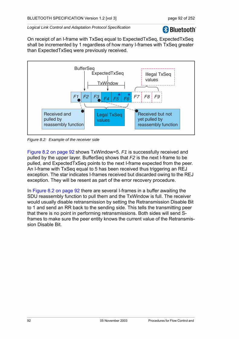
BLUETOOTH SPECIFICATION Version 1.2 [vol 3] page 92 of 252
Logical Link Control and Adaptation Protocol Specification
On receipt of an I-frame with TxSeq equal to ExpectedTxSeq, ExpectedTxSeq shall be incremented by 1 regardless of how many I-frames with TxSeq greater than ExpectedTxSeq were previously received.
Figure 8.2: Example of the receiver side
Figure 8.2 on page 92 shows TxWindow=5. F1 is successfully received and pulled by the upper layer. BufferSeq shows that F2 is the next I-frame to be pulled, and ExpectedTxSeq points to the next I-frame expected from the peer. An I-frame with TxSeq equal to 5 has been received thus triggering an REJ exception. The star indicates I-frames received but discarded owing to the REJ exception. They will be resent as part of the error recovery procedure.
In Figure 8.2 on page 92 there are several I-frames in a buffer awaiting the SDU reassembly function to pull them and the TxWindow is full. The receiver would usually disable retransmission by setting the Retransmission Disable Bit to 1 and send an RR back to the sending side. This tells the transmitting peer that there is no point in performing retransmissions. Both sides will send S-frames to make sure the peer entity knows the current value of the Retransmis-sion Disable Bit.
Received and pulled by reassembly function
Illegal TxSeq values
Legal TxSeq values
Received but not yet pulled by reassembly function
F1
BufferSeqExpectedTxSeq
TxWindow
F2 F3 F4 F5 F6 F7 F8 F9
92 05 November 2003 Procedures for Flow Control and

BLUETOOTH SPECIFICATION Version 1.2 [vol 3] page 93 of 252
Logical Link Control and Adaptation Protocol Specification
8.4 RETRANSMISSION MODE
8.4.1 Transmitting frames
A new I-frame shall only be transmitted when the TxWindow is not full. No I-frames shall be transmitted if the last RetransmissionDisableBit (R) received is set to one.
A previously transmitted I-frame may be retransmitted as a result of an error recovery procedure, even if the TxWindow is full. When an I-frame is retrans-mitted it shall always be sent with the same TxSeq value used in its initial transmission.
The state of the RetransmissionDisableBit (R) is stored and used along with the state of the RetransmissionTimer to decide the actions when transmitting I-frames. The RetransmissionTimer is running whenever I-frames have been sent but not acknowledged.
8.4.1.1 Last received R was set to zero
If the last R received was set to zero, then I-frames may be transmitted. If there are any I-frames which have been sent and not acknowledged then they shall be retransmitted when the RetransmissionTimer elapses. If the retrans-mission timer has not elapsed then a retransmission shall not be sent and only new I-frames may be sent.
a) If unacknowledged I-frames have been sent and the RetransmissionTimer has elapsed then an unacknowledged I-frame shall be retransmitted. The RetransmissionTimer shall be restarted.
b) If unacknowledged I-frames have been sent, the Retransmission timer has not elapsed then a new I-frame shall be sent if one is waiting and no timer action shall be taken.
c) If no unacknowledged I-frames have been sent, and a new I-frame is waiting, then the new I-frame shall be sent, the RetransmissionTimer shall be started and if the MonitorTimer is running, it shall be stopped.
d) If no unacknowledged I-frames have been sent and and no new I-frames are waiting to be transmitted, and the RetransmissionTimer is running, then the retransmission timer shall be stopped and the monitor timer shall be started.
Procedures for Flow Control and Retransmission 05 November 2003 93

BLUETOOTH SPECIFICATION Version 1.2 [vol 3] page 94 of 252
Logical Link Control and Adaptation Protocol Specification
The table below summarizes actions when the RetransmissionTimer is in use and R=0.
If the RetransmissionTimer is not in use, no unacknowledged I-frames have been sent and no new I-frames are waiting to be transmitted
a) If the MonitorTimer is running and has not elapsed then no transmit action shall be taken and no timer action shall be taken.
b) If the MonitorTimer has elapsed then an S-frame shall be sent and the MonitorTimer shall be restarted.
If any I-frames become available for transmission then the MonitorTimer shall be stopped, the RetransmissionTimer shall be started and the rules for when the RetransmissionTimer is in use shall be applied.
When an I-frame is sent ReqSeq shall be set to ExpectedTxSeq, TxSeq shall be set to NextTxSeq and NextTxSeq shall be incremented by one.
Unacknowledged I-frames sent = Retransmission Timer is running
Retrans-mission Timer has elapsed
New I-frames are waiting
Transmit Action
Timer Action
True True True or FalseRetransmit un-acknowledged I-frame
Restart Retransmission Timer
True False True Transmit new I-frame No timer action
True False False No transmit action
No Timer action
False False True Transmit new I-frame
Restart Retransmis-sion Timer
False False False No Transmit action
If MonitorTimer is not running then restart MonitorTimer
Table 8.1: Summary of actions when the RetransmissionTimer is in use and R=0.
94 05 November 2003 Procedures for Flow Control and

BLUETOOTH SPECIFICATION Version 1.2 [vol 3] page 95 of 252
Logical Link Control and Adaptation Protocol Specification
8.4.1.2 Last received R was set to one
If the last R received was set to one, then I-frames shall not be transmitted. The only frames which may be sent are S-frames. An S-frame shall be sent according to the rules below:
a) If the MonitorTimer is running and has not elapsed then no transmit action shall be taken and no timer action shall be taken.
b) If the MonitorTimer has elapsed then an S-frame shall be sent and the MonitorTimer shall be restarted.
8.4.2 Receiving I-frames
Upon receipt of a valid I-frame with TxSeq equal to ExpectedTxSeq, the frame shall be accepted for the SDU reassembly function. ExpectedTxSeq is used by the reassembly function.
The first valid I-frame received after an REJ was sent, with a TxSeq of the received I-frame equal to ReqSeq of the REJ, shall clear the REJ Exception condition.
The ReqSeq shall be processed according to Section 8.4.6 on page 97.
If a valid I-frame with TxSeq ≠ ExpectedTxSeq is received then an exception condition shall be triggered which is handled according to Section 8.4.7 on page 97.
8.4.3 I-frames pulled by the SDU reassembly function
When the L2CAP layer has removed one or more I-frames from the buffer, BufferSeq may be incremented in accordance with the amount of buffer space released. If BufferSeq is incremented, an acknowledgement shall be sent to the peer entity.
Note: Since the primary purpose of BufferSeq is to prevent buffer overflow, an implementation may choose to set BufferSeq in accordance with how many new incoming I-frames could be stored rather than how many have been removed.
The acknowledgement may either be an RR or an I-frame. The acknowledge-ment shall be sent to the peer L2CAP entity with ReqSeq equal to BufferSeq. When there are no I-frames buffered for pulling ExpectedTxSeq is equal to BufferSeq.
If the MonitorTimer is active then it shall be restarted to indicate that a signal has been sent to the peer L2CAP entity.
Procedures for Flow Control and Retransmission 05 November 2003 95

BLUETOOTH SPECIFICATION Version 1.2 [vol 3] page 96 of 252
Logical Link Control and Adaptation Protocol Specification
8.4.4 Sending and receiving acknowledgements
Either the MonitorTimer or the RetransmissionTimer shall be active while in Retransmission Mode. Both timers shall not be active concurrently.
8.4.4.1 Sending acknowledgements
Whenever an L2CAP entity transmits an I-frame or an S-frame, ReqSeq shall be set to ExpectedTxSeq or BufferSeq.
8.4.4.2 Receiving acknowledgements
On receipt of a valid S-frame or I-frame, the ReqSeq contained in the frame shall acknowledge previously transmitted I-frames. ReqSeq acknowledges I-frames with a TxSeq up to and including ReqSeq – 1.
The following rules shall be applied:
1. If the RetransmissionDisableBit changed value from 0 to 1 (stop retransmis-sions) then the receiving entity shall
a) If the RetransmissionTimer is running then stop it and start the MonitorTimer.
b) Store the state of the RetransmissionDisableBit received.
2. If the RetransmissionDisableBit changed value from 1 to 0 (start retransmis-sions) then the receiving entity shall
a) Store the state of the RetransmissionDisableBit received.b) If there are any I-frames that have been sent but not
acknowledged, then stop the MonitorTimer and start the RetransmissionTimer.
c) Any buffered I-frames shall be transmitted according to Section 8.4.1 on page 93.
3. If any unacknowledged I-frames were acknowledged by the ReqSeq con-tained in the frame, and the RetransmissionDisableBit equals 1 (retransmis-sions stopped), then the receiving entity shall
a) Follow the rules in Section 8.4.1 on page 93.
4. If any unacknowledged I-frames were acknowledged by the ReqSeq con-tained in the frame and the RetransmissionDisableBit equals 0 (retransmis-sions started) then the receiving entity shall
a) If the RetransmissionTimer is running, then stop it.b) If any unacknowledged I-frames have been sent then the
RetransmissionTimer shall be restarted.
96 05 November 2003 Procedures for Flow Control and

BLUETOOTH SPECIFICATION Version 1.2 [vol 3] page 97 of 252
Logical Link Control and Adaptation Protocol Specification
c) Follow the rules in Section 8.4.1 on page 93.d) If the RetransmissionTimer is not running and the MonitorTimer is
not running, then start the MonitorTimer.
On receipt of a valid S-frame or I-frame the ReqSeq contained in the frame shall acknowledge previously transmitted I-frames. ExpectedAckSeq shall be set to ReqSeq to indicate that the I-frames with TxSeq up to and including (ReqSeq - 1) have been acknowledged.
8.4.5 Receiving REJ frames
Upon receipt of a valid REJ frame, where ReqSeq identifies an I-frame not yet acknowledged, the ReqSeq acknowledges I-frames with TxSeq up to and including ReqSeq - 1. Therefore the REJ acknowledges all I-frames before the I-frame it is rejecting.
ExpectedAckSeq shall be set equal to ReqSeq to mark I-frames up to and including ReqSeq - 1 as received.
NextTXSeq shall be set to ReqSeq to cause transmissions of I-frames to resume from the point where TxSeq equals ReqSeq.
If ReqSeq equals ExpectedAckSeq then the REJ frame shall be ignored.
8.4.6 Waiting acknowledgements
A counter, TransmitCounter, counts the number of times an L2CAP PDU has been transmitted. This shall be set to 1 after the first transmission. If the RetransmissionTimer expires the following actions shall be taken:
1. If the TransmitCounter is less than MaxTransmit then:a) Increment the TransmitCounterb) Retransmit the last unacknowledged I-frame, according to Section
8.4.1 on page 93.
2. If the TransmitCounter is equal to MaxTransmit this channel to the peer entity shall be assumed lost. The channel shall move to the CLOSED state and appropriate action shall be taken to report this to the upper layers.
8.4.7 Exception conditions
Exception conditions may occur as the result of physical layer errors or L2CAP procedural errors. The error recovery procedures which are available following the detection of an exception condition at the L2CAP layer in Retransmission Mode are defined in this section.
8.4.7.1 TxSeq Sequence error
A TxSeq sequence error exception condition occurs in the receiver when a valid I-frame is received which contains a TxSeq value which is not equal to the expected value, thus TxSeq is not equal to ExpectedTxSeq.
Procedures for Flow Control and Retransmission 05 November 2003 97

BLUETOOTH SPECIFICATION Version 1.2 [vol 3] page 98 of 252
Logical Link Control and Adaptation Protocol Specification
The TxSeq sequence error may be due to three different causes:
• Duplicated I-frameThe duplicated I-frame is identified by a TxSeq in the range BufferSeq to ExpectedTxSeq – 1 (BufferSeq ≤TxSeq<ExpectedTxSeq). The ReqSeq and RetransmissionDisableBit shall be processed according to Section 8.4.4 on page 96. The Information field shall be discarded since it has already been received.
• Out-of-sequence I-frameThe out-of-sequence I-frame is identified by a TxSeq within the legal range. The ReqSeq and RetransmissionDisableBit shall be processed according to Section 8.4.4 on page 96.A REJ exception is triggered, and an REJ frame with ReqSeq equal to ExpectedTxSeq shall be sent to initiate recovery. The received I-frame shall be discarded.
• Invalid TxSeqAn invalid TxSeq value is a value that does not meet either of the above conditions. An I-frame with an invalid TxSeq is likely to have errors in the control field and shall be silently discarded.
8.4.7.2 ReqSeq Sequence error
An ReqSeq sequence error exception condition occurs in the transmitter when a valid S-frame or I-frame is received which contains an invalid ReqSeq value. An invalid ReqSeq is one that is not in the range ExpectedAckSeq ≤ ReqSeq ≤ NextTxSeq.
The L2CAP entity shall close the channel as a consequence of an ReqSeq Sequence error.
8.4.7.3 Timer recovery error
If an L2CAP entity fails to receive an acknowledgement for the last I-frame sent, then it will not detect an out-of-sequence exception condition and there-fore will not transmit an REJ frame.
The L2CAP entity that transmitted an unacknowledged I-frame shall, on the expiry of the RetransmissionTimer, take appropriate recovery action as defined in Section 8.4.6 on page 97.
8.4.7.4 Invalid frame
Any frame received which is invalid (as defined in Section 3.3.6 on page 40) shall be discarded, and no action shall be taken as a result of that frame.
98 05 November 2003 Procedures for Flow Control and

BLUETOOTH SPECIFICATION Version 1.2 [vol 3] page 99 of 252
Logical Link Control and Adaptation Protocol Specification
8.5 FLOW CONTROL MODE
When a link is configured to work in flow control mode, the flow control opera-tion is similar to the procedures in retransmission mode, but all operations dealing with CRC errors in received packets are not used. Therefore
• REJ frames shall not be used in Flow Control Mode.
• The RetransmissionDisableBit shall always be set to zero in the transmitter, and shall be ignored in the receiver.
The behaviour of flow control mode is specified in this section.
Assuming that the TxWindow size is equal to the buffer space available in the receiver (counted in number of I-frames), in flow control mode the number of unacknowledged frames in the transmitter window is always less than or equal to the number of frames for which space is available in the receiver. Note that a missing frame still occupies a place in the window.
Figure 8.3: Overview of the receiver side when operating in flow control mode
8.5.1 Transmitting I-frames
A new I-frame shall only be transmitted when the TxWindow is not full.
Upon transmission of the I-frame the following actions shall be performed:
• If no unacknowledged I-frames have been sent then the MonitorTimer shall be stopped and the RetransmissionTimer shall be started.
• If any I-frames have been sent and not acknowledged then the Retransmis-sionTimer remains active and no timer operation is performed.
The control field parameter ReqSeq shall be set to ExpectedTxSeq, TxSeq shall be set to NextTXSeq and NextTXSeq shall be incremented by one.
Received and pulled by reassembly function
Illegal TxSeq values
Legal TxSeqvalues
Received but not yet pulled by reassembly function
1 2 3 4 5 6 7 8 9
BufferSeqExpectedTxSeq
TxWindow
Missing (lost or corrupted) I-frame
Procedures for Flow Control and Retransmission 05 November 2003 99
BLUETOOTH SPECIFICATION Version 1.2 [vol 3] page 100 of 252
Logical Link Control and Adaptation Protocol Specification
8.5.2 Receiving I-frames
Upon receipt of a valid I-frame with TxSeq equal to ExpectedTxSeq, the frame shall be made available to the reassembly function. ExpectedTxSeq shall be incremented by one. An acknowledgement shall not be sent until the SDU reassembly function has pulled the I-frame.
Upon receipt of a valid I-frame with an out-of-sequence TxSeq (see Section 8.5.6 on page 101) all frames with a sequence number less than TxSeq shall be assumed lost and marked as missing. The missing I-frames are in the range from ExpectedTxSeq (the frame that the device was expecting to receive) up to TxSeq-1, (the frame that the device actually received). ExpectedTxSeq shall be set to TxSeq +1. The received I-frame shall be made available for pulling by the reassembly function. The acknowledgement shall not occur until the SDU reassembly function has pulled the I-frame. The ReqSeq shall be processed according to Section 8.5.4 on page 100.
8.5.3 I-frames pulled by the SDU reassembly function
When the L2CAP layer has removed one or more I-frames from the buffer, BufferSeq may be incremented in accordance with the amount of buffer space released. If BufferSeq is incremented, an acknowledgement shall be sent to the peer entity. If the MonitorTimer is active then it shall be restarted to indicate that a signal has been sent to the peer L2CAP entity.
Note: Since the primary purpose of BufferSeq is to prevent buffer overflow, an implementation may choose to set BufferSeq in accordance with how many new incoming I-frames could be stored rather than how many have been removed.
The acknowledgement may be an RR or an I-frame. The acknowledgement shall be sent to the peer L2CAP entity with ReqSeq equal to BufferSeq. When there is no I-frame buffered for pulling, ExpectedTxSeq is equal to BufferSeq.
8.5.4 Sending and receiving acknowledgements
One of the timers MonitorTimer or RetransmissionTimer shall always be active while in Flow Control mode. Both timers shall never be active concurrently.
8.5.4.1 Sending acknowledgements
Whenever a data link layer entity transmits an I-frame or a S-frame, ReqSeq shall be set to ExpectedTxSeq or BufferSeq.
8.5.4.2 Receiving acknowledgements
On receipt of a valid S-frame or I-frame the ReqSeq contained in the frame shall be used to acknowledge previously transmitted I-frames. ReqSeq acknowledges I-frames with a TxSeq up to and including ReqSeq – 1.
100 05 November 2003 Procedures for Flow Control and

BLUETOOTH SPECIFICATION Version 1.2 [vol 3] page 101 of 252
Logical Link Control and Adaptation Protocol Specification
1. If any outstanding I-frames were acknowledged thena) Stop the RetransmissionTimerb) If there are still unacknowledged I-frames then restart the
RetransmissionTimer, otherwise start the MonitorTimer.c) Transmit any I-frames awaiting transmission according to Section
8.5.1 on page 99.
ExpectedAckSeq shall be set to ReqSeq to indicate that the I-frames with TxSeq up to and including ExpectedAckSeq have been acknowledged.
8.5.5 Waiting acknowledgements
If the RetransmissionTimer expires the following actions shall be taken: The I-frame supervised by the RetransmissionTimer shall be considered lost, and ExpectedAckSeq shall be incremented by one.
1. If I-frames are waiting to be senta) The RetransmissionTimer is restartedb) I-frames awaiting transmission are transmitted according to
Section 8.5.1 on page 99.
2. If there are no I-frames waiting to be senta) If there are still unacknowledged I-frames the RetransmissionTimer
is restarted, otherwise the MonitorTimer is started.
8.5.6 Exception conditions
Exception conditions may occur as the result of physical layer errors or L2CAP procedural errors. The error recovery procedures which are available following the detection of an exception condition at the L2CAP layer in flowcontrol only mode are defined in this section.
8.5.6.1 TxSeq Sequence error
A TxSeq sequence error exception condition occurs in the receiver when a valid I-frame is received which contains a TxSeq value which is not equal to the expected value, thus TxSeq is not equal to ExpectedTxSeq.
The TxSeq sequence error may be due to three different causes:
• Duplicated I-frameThe duplicated I-frame is identified by a TxSeq in the range BufferSeq to ExpectedTxSeq – 1. The ReqSeq shall be processed according to Section 8.5.4 on page 100. The Information field shall be discarded since it has already been received.
Procedures for Flow Control and Retransmission 05 November 2003 101

BLUETOOTH SPECIFICATION Version 1.2 [vol 3] page 102 of 252
Logical Link Control and Adaptation Protocol Specification
• Out-of-sequence I-frameThe out-of-sequence I-frame is identified by a TxSeq within the legal range ExpectedTxSeq < TxSeq < (BufferSeq + TxWindow). The ReqSeq shall be processed according to Section 8.5.4 on page 100.The missing I-frame(s) are considered lost and ExpectedTXSeq is set equal to TxSeq+1 as specified in Section 8.5.2 on page 100. The missing I-frame(s) are reported as lost to the SDU reassembly function.
• Invalid TxSeqAn invalid TxSeq value is a value that does not meet either of the above conditions and TxSeq is not equal to ExpectedTxSeq. An I-frame with an invalid TxSeq is likely to have errors in the control field and shall be silently discarded.
8.5.6.2 ReqSeq Sequence error
An ReqSeq sequence error exception condition occurs in the transmitter when a valid S-frame or I-frame is received which contains an invalid ReqSeq value. An invalid ReqSeq is one that is not in the range ExpectedAckSeq ≤ ReqSeq ≤ NextTXSeq.
The L2CAP entity shall close the channel as a consequence of an ReqSeq Sequence error.
8.5.6.3 Timer recovery error
An L2CAP entity that fails to receive an acknowledgement for an I-frame shall, on the expiry of the RetransmissionTimer, take appropriate recovery action as defined in Section 8.5.5 on page 101.
8.5.6.4 Invalid frame
Any frame received that is invalid (as defined in Section 3.3.6 on page 40) shall be discarded, and no action shall be taken as a result of that frame, unless the receiving L2CAP entity is configured to deliver erroneous frames to the layer above L2CAP. In that case, the data contained in invalid frames may also be added to the receive buffer and made available for pulling from the SDU reas-sembly function.
102 05 November 2003 Procedures for Flow Control and

BLUETOOTH SPECIFICATION Version 1.2 [vol 3] page 103 of 252
Logical Link Control and Adaptation Protocol Specification
9 LIST OF FIGURES
Figure 1.1: L2CAP within protocol layers ....................................................21Figure 1.2: L2CAP data flows in Bluetooth Protocol Architecture ...............22Figure 1.3: L2CAP architectural blocks ......................................................22
Figure 2.1: Channels between devices .......................................................30Figure 2.2: L2CAP transaction model. ........................................................31
Figure 3.1: PDU format in Basic L2CAP mode on connection-oriented channels (field sizes in bits) ......................................................33
Figure 3.2: L2CAP PDU format in Basic L2CAP mode on Connectionless channel 34
Figure 3.3: L2CAP PDU formats in Flow Control and Retransmission Modes 35Figure 3.4: The LFSR circuit generating the FCS. ......................................39Figure 3.5: Initial state of the FCS generating circuit...................................... 39
Figure 4.1: L2CAP PDU format on the signalling channel ..........................41Figure 4.2: Command format ......................................................................41Figure 4.3: Command Reject packet ...........................................................43Figure 4.4: Connection Request Packet ......................................................44Figure 4.5: Connection Response Packet ...................................................46Figure 4.6: Configuration Request Packet ..................................................48Figure 4.7: Configuration Request Flags field format ..................................48Figure 4.8: Configuration Response Packet ................................................50Figure 4.9: Configuration Response Flags field format ...............................50Figure 4.10: Disconnection Request Packet .................................................52Figure 4.11: Disconnection Response Packet ..............................................53Figure 4.12: Echo Request Packet ...............................................................53Figure 4.13: Echo Response Packet .............................................................54Figure 4.14: Information Request Packet ......................................................54Figure 4.15: Information Response Packet ...................................................55
Figure 5.1: Configuration option format .......................................................57Figure 5.2: MTU Option Format ..................................................................58Figure 5.3: Flush Timeout option format. ....................................................59Figure 5.4: Quality of Service (QoS) option format containing Flow
Specification. .............................................................................61Figure 5.5: Retransmission and Flow Control option format. ......................64
Figure 6.1: States and transitions. ...............................................................76Figure 6.2: Configuration states and transitions. .........................................77
List of Figures 05 November 2003 103

BLUETOOTH SPECIFICATION Version 1.2 [vol 3] page 104 of 252
Logical Link Control and Adaptation Protocol Specification
Figure 7.1: L2CAP fragmentation. ...............................................................81Figure 7.2: Example of fragmentation processes in a device with HCI. ......82Figure 7.3: Segmentation and fragmentation of an SDU. ...........................83Figure 7.4: Example of segmentation and fragment processes in a device
with HCI ....................................................................................84
Figure 8.1: Example of the transmitter side ................................................90Figure 8.2: Example of the receiver side ....................................................92Figure 8.3: Overview of the receiver side when operating in flow control
mode .........................................................................................99
104 05 November 2003 List of Figures
BLUETOOTH SPECIFICATION Version 1.2 [vol 3] page 105 of 252
Logical Link Control and Adaptation Protocol Specification
10 LIST OF TABLES
Table 1.1: Terminology................................................................................26
Table 2.1: CID name space ........................................................................29Table 2.2: Types of Channel Identifiers.......................................................30
Table 3.1: Control Field formats..................................................................36Table 3.2: SAR control element format. ......................................................37Table 3.3: S control element format: type of S-frame. ................................37
Table 4.1: Signalling Command Codes.......................................................42Table 4.2: Reason Code Descriptions ........................................................43Table 4.3: Reason Data values...................................................................44Table 4.4: Defined PSM Values ..................................................................45Table 4.5: Result values .............................................................................46Table 4.6: Status values..............................................................................47Table 4.7: Configuration Response Result codes.......................................51Table 4.8: InfoType definitions ....................................................................54Table 4.9: Information Response Result values .........................................55Table 4.10: Information Response Data fields ..............................................56Table 4.11: Extended feature mask. .............................................................56
Table 5.1: Service type definitions ..............................................................61Table 5.2: Mode definitions. ........................................................................64
Table 6.1: CLOSED state event table. ........................................................68Table 6.2: WAIT_CONNECT_RSP state event table..................................69Table 6.3: WAIT_CONNECT state event table. ..........................................69Table 6.4: CONFIG state/substates event table: success transitions within
configuration process. ................................................................70Table 6.5: CONFIG state/substates event table: non-success transitions
within configuration process.......................................................71Table 6.6: CONFIG state/substates event table: events not related to
configuration process. ................................................................72Table 6.7: OPEN state event table..............................................................73Table 6.8: WAIT_DISCONNECT state event table. ....................................73
Table 7.1: Parameters allowed in Request .................................................80Table 7.2: Parameters allowed in Response ..............................................80
Table 8.1: Summary of actions when the RetransmissionTimer is in use and R=0. ...........................................................................................94
List of Tables 05 November 2003 105

BLUETOOTH SPECIFICATION Version 1.2 [vol 3] page 106 of 252
Logical Link Control and Adaptation Protocol Specification
11 APPENDIX
106 05 November 2003 Appendix
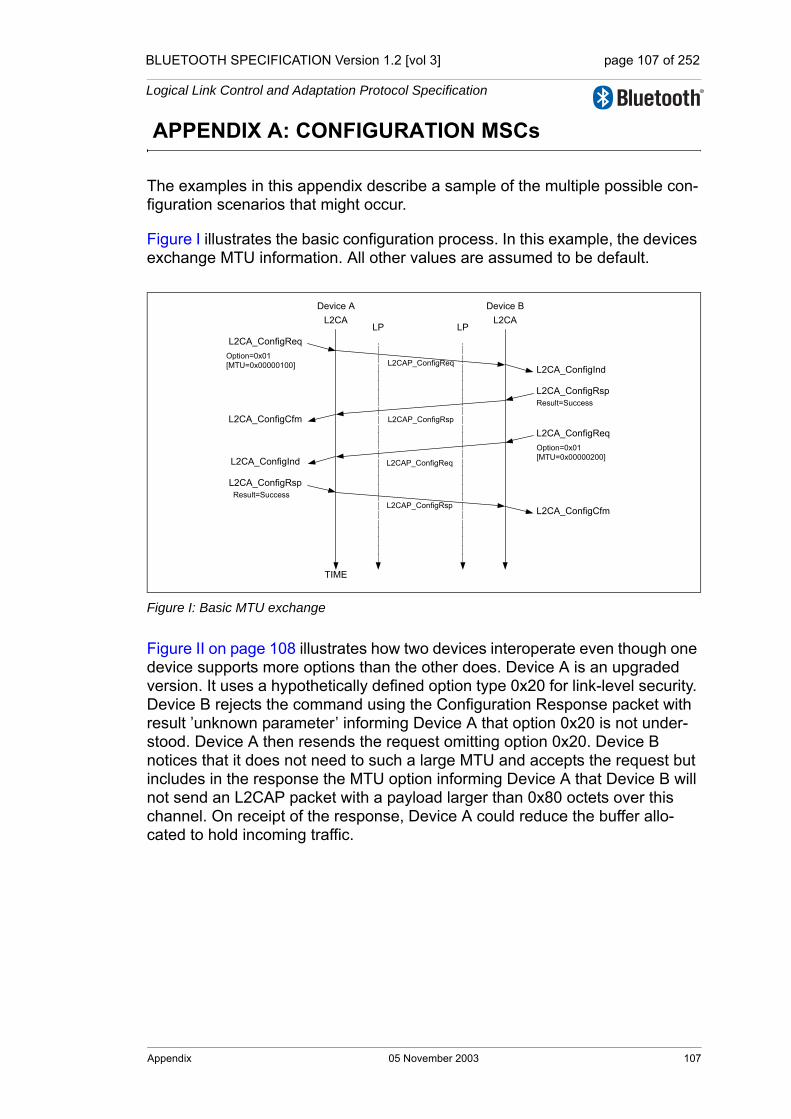
BLUETOOTH SPECIFICATION Version 1.2 [vol 3] page 107 of 252
Logical Link Control and Adaptation Protocol Specification
APPENDIX A: CONFIGURATION MSCs
The examples in this appendix describe a sample of the multiple possible con-figuration scenarios that might occur.
Figure I illustrates the basic configuration process. In this example, the devices exchange MTU information. All other values are assumed to be default.
Figure I: Basic MTU exchange
Figure II on page 108 illustrates how two devices interoperate even though one device supports more options than the other does. Device A is an upgraded version. It uses a hypothetically defined option type 0x20 for link-level security. Device B rejects the command using the Configuration Response packet with result ’unknown parameter’ informing Device A that option 0x20 is not under-stood. Device A then resends the request omitting option 0x20. Device B notices that it does not need to such a large MTU and accepts the request but includes in the response the MTU option informing Device A that Device B will not send an L2CAP packet with a payload larger than 0x80 octets over this channel. On receipt of the response, Device A could reduce the buffer allo-cated to hold incoming traffic.
L2CAP_ConfigReq
Device A Device B
L2CAP_ConfigRsp
L2CA_ConfigReq
L2CA_ConfigInd
L2CA_ConfigRsp
L2CA_ConfigCfm
TIME
LP LPL2CA L2CA
Option=0x01[MTU=0x00000100]
Result=Success
L2CA_ConfigReq
L2CA_ConfigIndOption=0x01[MTU=0x00000200]
L2CA_ConfigRsp
L2CA_ConfigCfm
Result=SuccessL2CAP_ConfigRsp
L2CAP_ConfigReq
Appendix 05 November 2003 107

BLUETOOTH SPECIFICATION Version 1.2 [vol 3] page 108 of 252
Logical Link Control and Adaptation Protocol Specification
Figure II: Dealing with Unknown Options
Figure III on page 109 illustrates an unsuccessful configuration request. There are two problems described by this example. The first problem is that the con-figuration request is placed in an L2CAP packet that cannot be accepted by the remote device, due to its size. The remote device informs the sender of this problem using the Command Reject message. Device A then resends the con-figuration options using two smaller L2CAP_ConfigReq messages.
The second problem is an attempt to configure a channel with an invalid CID. For example device B may not have an open connection on that CID (0x01234567 in this example case).
Device A Device B
TIME
LP LPL2CA L2CA
L2CAP_ConfigReq
L2CAP_ConfigRsp
L2CA_ConfigReq
L2CA_ConfigInd
L2CA_ConfigRsp
L2CA_ConfigCfm
Option=0x01[MTU=0x00000100]Option=0x20[Data=0xFA12D823]
Result=Unknown optionOption=0x20
L2CAP_ConfigReq
L2CAP_ConfigRsp
L2CA_ConfigReq
L2CA_ConfigInd
L2CA_ConfigRsp
L2CA_ConfigCfm
Option=0x01[MTU=0x00000100]
Result=Success[MTU=0x00000080]
L2CA_ConfigReq
L2CA_ConfigIndOption=0x01[MTU=0x00000200]
L2CA_ConfigRsp
L2CA_ConfigCfm
Result=Success
L2CAP_ConfigReq
L2CAP_ConfigRsp
108 05 November 2003 Appendix
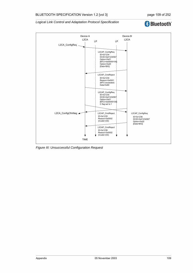
BLUETOOTH SPECIFICATION Version 1.2 [vol 3] page 109 of 252
Logical Link Control and Adaptation Protocol Specification
Figure III: Unsuccessful Configuration Request
Device A Device B
TIME
LP LPL2CA L2CA
L2CAP_ConfigReq
L2CAP_CmdReject
L2CA_ConfigReq
ID=0x1234DCID=0x01234567Option=0x01[MTU=0x00000100]Option=0x20[Data=BIG]
ID=0x1234Reason=0x0001(MTU exceeded)Data=0x80
L2CAP_CmdReject
L2CAP_ConfigReqID=0x1235DCID=0x01234567Option=0x01[MTU=0x00000100]C flag set to 1
ID=0x1235Reason=0x0002(Invalid CID)
L2CAP_CmdRejectID=0x1236Reason=0x0002(Invalid CID)
L2CAP_ConfigReq
ID=0x1236DCID=0x01234567Option=0x20[Data=BIG]
L2CA_ConfigCfmNeg
Appendix 05 November 2003 109

BLUETOOTH SPECIFICATION Version 1.2 [vol 3] page 110 of 252
Logical Link Control and Adaptation Protocol Specification
110 05 November 2003 Appendix
Core System Package [Host volume]
Part BSERVICE DISCOVERYPROTOCOL (SDP)
This specification defines a protocol for locating services provided by or available through a Bluetooth device.

BLUETOOTH SPECIFICATION Version 1.2 [vol 3] page 112 of 252
Service Discovery Protocol (SDP)
112 05 November 2003

BLUETOOTH SPECIFICATION Version 1.2 [vol 3] page 113 of 252
Service Discovery Protocol (SDP)
CONTENTS
1 Introduction ......................................................................................1151.1 General Description .................................................................1151.2 Motivation.................................................................................1151.3 Requirements...........................................................................1151.4 Non-requirements and Deferred Requirements .......................1161.5 Conventions .............................................................................116
1.5.1 Bit And Byte Ordering Conventions.............................116
2 Overview ...........................................................................................1172.1 SDP Client-Server Interaction..................................................1172.2 Service Record.........................................................................1182.3 Service Attribute.......................................................................1202.4 Attribute ID ...............................................................................1202.5 Attribute Value..........................................................................1212.6 Service Class ...........................................................................121
2.6.1 A Printer Service Class Example ................................1222.7 Searching for Services.............................................................123
2.7.1 UUID............................................................................1232.7.2 Service Search Patterns..............................................124
2.8 Browsing for Services ..............................................................1242.8.1 Example Service Browsing Hierarchy .........................125
3 Data Representation.........................................................................1273.1 Data Element ...........................................................................1273.2 Data Element Type Descriptor .................................................1273.3 Data Element Size Descriptor ..................................................1283.4 Data Element Examples...........................................................129
4 Protocol Description........................................................................1314.1 Transfer Byte Order .................................................................1314.2 Protocol Data Unit Format........................................................1314.3 Partial Responses and Continuation State...............................1334.4 Error Handling..........................................................................133
4.4.1 SDP_ErrorResponse PDU ..........................................1344.5 ServiceSearch Transaction ......................................................135
4.5.1 SDP_ServiceSearchRequest PDU..............................1354.5.2 SDP_ServiceSearchResponse PDU...........................136
4.6 ServiceAttribute Transaction ....................................................1384.6.1 SDP_ServiceAttributeRequest PDU............................1384.6.2 SDP_ServiceAttributeResponse PDU.........................140
4.7 ServiceSearchAttribute Transaction.........................................141
05 November 2003 113

BLUETOOTH SPECIFICATION Version 1.2 [vol 3] page 114 of 252
Service Discovery Protocol (SDP)
4.7.1 SDP_ServiceSearchAttributeRequest PDU................1414.7.2 SDP_ServiceSearchAttributeResponse PDU .............143
5 Service Attribute Definitions...........................................................1455.1 Universal Attribute Definitions..................................................145
5.1.1 ServiceRecordHandle Attribute...................................1455.1.2 ServiceClassIDList Attribute........................................1465.1.3 ServiceRecordState Attribute ......................................1465.1.4 ServiceID Attribute ......................................................1465.1.5 ProtocolDescriptorList Attribute...................................1475.1.6 BrowseGroupList Attribute ..........................................1485.1.7 LanguageBaseAttributeIDList Attribute .......................1485.1.8 ServiceInfoTimeToLive Attribute .................................1495.1.9 ServiceAvailability Attribute.........................................1505.1.10 BluetoothProfileDescriptorList Attribute ......................1505.1.11 DocumentationURL Attribute ......................................1515.1.12 ClientExecutableURL Attribute....................................1515.1.13 IconURL Attribute........................................................1525.1.14 ServiceName Attribute ................................................1525.1.15 ServiceDescription Attribute........................................1535.1.16 ProviderName Attribute...............................................1535.1.17 Reserved Universal Attribute IDs ................................153
5.2 ServiceDiscoveryServer Service Class Attribute Definitions ...1545.2.1 ServiceRecordHandle Attribute...................................1545.2.2 ServiceClassIDList Attribute........................................1545.2.3 VersionNumberList Attribute .......................................1545.2.4 ServiceDatabaseState Attribute ..................................1555.2.5 Reserved Attribute IDs ................................................155
5.3 BrowseGroupDescriptor Service Class Attribute Definitions ...1555.3.1 ServiceClassIDList Attribute........................................1555.3.2 GroupID Attribute ........................................................1565.3.3 Reserved Attribute IDs ................................................156
Appendix ABackground Information ...........................................................................157
Appendix B Example SDP Transactions .......................................................................158
114 05 November 2003
BLUETOOTH SPECIFICATION Version 1.2 [vol 3] page 115 of 252
Service Discovery Protocol (SDP)
1 INTRODUCTION
1.1 GENERAL DESCRIPTION
The service discovery protocol (SDP) provides a means for applications to dis-cover which services are available and to determine the characteristics of those available services.
1.2 MOTIVATION
Service Discovery in the Bluetooth environment, where the set of services that are available changes dynamically based on the RF proximity of devices in motion, is qualitatively different from service discovery in traditional network-based environments. The service discovery protocol defined in this specifica-tion is intended to address the unique characteristics of the Bluetooth environ-ment. See Section , “Appendix A – Background Information,” on page 157, for further information on this topic.
1.3 REQUIREMENTS
The following capabilities have been identified as requirements for version 1.0 of the Service Discovery Protocol.
1. SDP shall provide the ability for clients to search for needed services based on specific attributes of those services.
2. SDP shall permit services to be discovered based on the class of service.
3. SDP shall enable browsing of services without a priori knowledge of the spe-cific characteristics of those services.
4. SDP shall provide the means for the discovery of new services that become available when devices enter RF proximity with a client device as well as when a new service is made available on a device that is in RF proximity with the client device.
5. SDP shall provide a mechanism for determining when a service becomes unavailable when devices leave RF proximity with a client device as well as when a service is made unavailable on a device that is in RF proximity with the client device.
6. SDP shall provide for services, classes of services, and attributes of ser-vices to be uniquely identified.
7. SDP shall allow a client on one device to discover a service on another device without consulting a third device.
8. SDP should be suitable for use on devices of limited complexity.
9. SDP shall provide a mechanism to incrementally discover information about the services provided by a device. This is intended to minimize the quantity
Introduction 05 November 2003 115
BLUETOOTH SPECIFICATION Version 1.2 [vol 3] page 116 of 252
Service Discovery Protocol (SDP)
of data that must be exchanged in order to determine that a particular ser-vice is not needed by a client.
10.SDP should support the caching of service discovery information by inter-mediary agents to improve the speed or efficiency of the discovery process.
11.SDP should be transport independent.
12.SDP shall function while using L2CAP as its transport protocol.
13.SDP shall permit the discovery and use of services that provide access to other service discovery protocols.
14.SDP shall support the creation and definition of new services without requir-ing registration with a central authority.
1.4 NON-REQUIREMENTS AND DEFERRED REQUIREMENTS
The Bluetooth SIG recognizes that the following capabilities are related to ser-vice discovery. These items are not addressed in SDP version 1.0. However, some may be addressed in future revisions of the specification.
1. SDP 1.0 does not provide access to services. It only provides access to information about services.
2. SDP 1.0 does not provide brokering of services.
3. SDP 1.0 does not provide for negotiation of service parameters.
4. SDP 1.0 does not provide for billing of service use.
5. SDP 1.0 does not provide the means for a client to control or change the operation of a service.
6. SDP 1.0 does not provide an event notification when services, or information about services, become unavailable.
7. SDP 1.0 does not provide an event notification when attributes of services are modified.
8. This specification does not define an application programming interface for SDP.
9. SDP 1.0 does not provide support for service agent functions such as ser-vice aggregation or service registration.
1.5 CONVENTIONS
1.5.1 Bit And Byte Ordering Conventions
When multiple bit fields are contained in a single byte and represented in a drawing in this specification, the more significant (high-order) bits are shown toward the left and less significant (low-order) bits toward the right.
Multiple-byte fields are drawn with the more significant bytes toward the left and the less significant bytes toward the right. Multiple-byte fields are trans-ferred in network byte order. See section 4.1 on page 131.
116 05 November 2003 Introduction

BLUETOOTH SPECIFICATION Version 1.2 [vol 3] page 117 of 252
Service Discovery Protocol (SDP)
2 OVERVIEW
2.1 SDP CLIENT-SERVER INTERACTION
Figure 2.1:
The service discovery mechanism provides the means for client applications to discover the existence of services provided by server applications as well as the attributes of those services. The attributes of a service include the type or class of service offered and the mechanism or protocol information needed to utilize the service.
As far as the Service Discovery Protocol (SDP) is concerned, the configuration shown in Figure 1 may be simplified to that shown in Figure 2.
Figure 2.2:
SDPClient
SDPServer
SDP requests
SDP responses
ServerApplication
ClientApplication
SDPClient
SDPServer
SDP requests
SDP responses
Overview 05 November 2003 117
BLUETOOTH SPECIFICATION Version 1.2 [vol 3] page 118 of 252
Service Discovery Protocol (SDP)
SDP involves communication between an SDP server and an SDP client. The server maintains a list of service records that describe the characteristics of services associated with the server. Each service record contains information about a single service. A client may retrieve information from a service record maintained by the SDP server by issuing an SDP request.
If the client, or an application associated with the client, decides to use a ser-vice, it must open a separate connection to the service provider in order to uti-lize the service. SDP provides a mechanism for discovering services and their attributes (including associated service access protocols), but it does not pro-vide a mechanism for utilizing those services (such as delivering the service access protocols).
There is a maximum of one SDP server per Bluetooth device. (If a Bluetooth device acts only as a client, it needs no SDP server.) A single Bluetooth device may function both as an SDP server and as an SDP client. If multiple applica-tions on a device provide services, an SDP server may act on behalf of those service providers to handle requests for information about the services that they provide.
Similarly, multiple client applications may utilize an SDP client to query servers on behalf of the client applications.
The set of SDP servers that are available to an SDP client can change dynam-ically based on the RF proximity of the servers to the client. When a server becomes available, a potential client must be notified by a means other than SDP so that the client can use SDP to query the server about its services. Sim-ilarly, when a server leaves proximity or becomes unavailable for any reason, there is no explicit notification via the service discovery protocol. However, the client may use SDP to poll the server and may infer that the server is not avail-able if it no longer responds to requests.
Additional information regarding application interaction with SDP is contained in the Bluetooth Service Discovery Profile document.
2.2 SERVICE RECORD
A service is any entity that can provide information, perform an action, or con-trol a resource on behalf of another entity. A service may be implemented as software, hardware, or a combination of hardware and software.
All of the information about a service that is maintained by an SDP server is contained within a single service record. The service record consists entirely of a list of service attributes.
118 05 November 2003 Overview

BLUETOOTH SPECIFICATION Version 1.2 [vol 3] page 119 of 252
Service Discovery Protocol (SDP)
Figure 2.3: Service Record
A service record handle is a 32-bit number that uniquely identifies each service record within an SDP server. It is important to note that, in general, each han-dle is unique only within each SDP server. If SDP server S1 and SDP server S2 both contain identical service records (representing the same service), the service record handles used to reference these identical service records are completely independent. The handle used to reference the service on S1 will be meaningless if presented to S2.
The service discovery protocol does not provide a mechanism for notifying cli-ents when service records are added to or removed from an SDP server. While an L2CAP (Logical Link Control and Adaptation Protocol) connection is estab-lished to a server, a service record handle acquired from the server will remain valid unless the service record it represents is removed. If a service is removed from the server, further requests to the server (during the L2CAP connection in which the service record handle was acquired) using the service’s (now stale) record handle will result in an error response indicating an invalid service record handle. An SDP server must ensure that no service record handle val-ues are re-used while an L2CAP connection remains established. Note that service record handles are known to remain valid across successive L2CAP connections while the ServiceDatabaseState attribute value remains unchanged. See the ServiceRecordState and ServiceDatabaseState attributes in section 5 on page 145.
There is one service record handle whose meaning is consistent across all SDP servers. This service record handle has the value 0x00000000 and is a handle to the service record that represents the SDP server itself. This service record contains attributes for the SDP server and the protocol it supports. For example, one of its attributes is the list of SDP protocol versions supported by the server. Service record handle values 0x00000001-0x0000FFFF are reserved.
Service Attribute 1
Service Attribute 2
Service Attribute 3
Service Attribute N
Service Record
. . .
Overview 05 November 2003 119
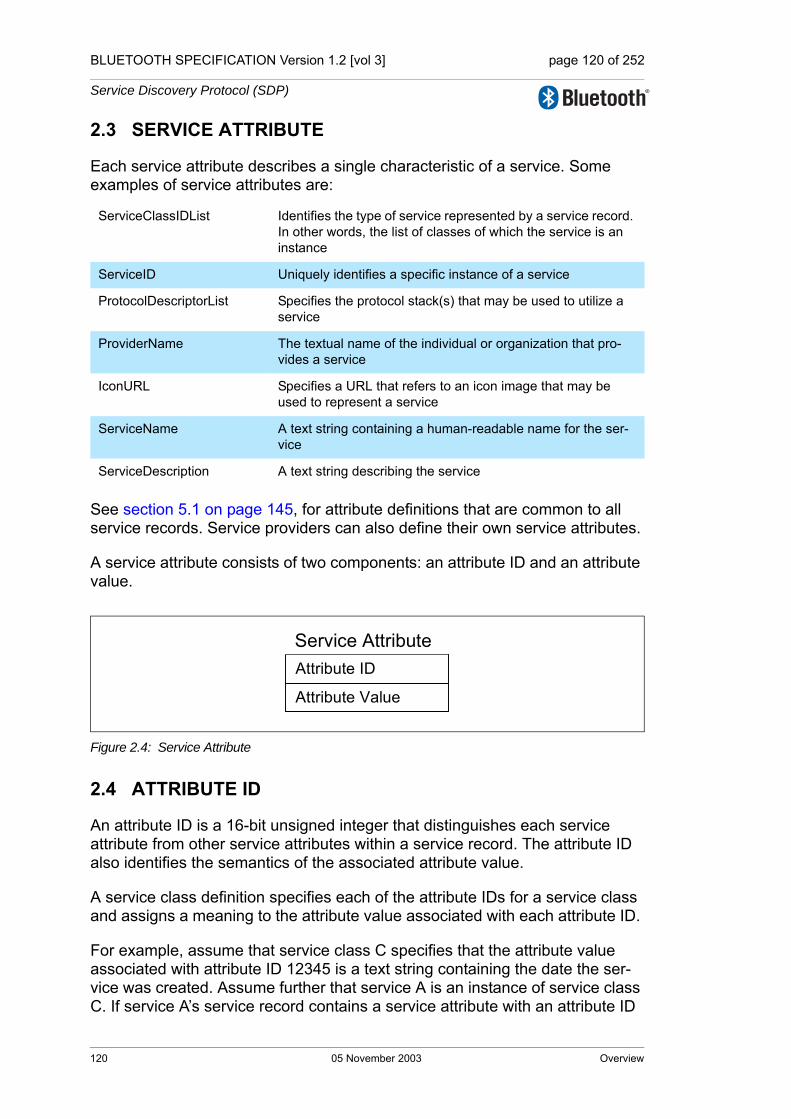
BLUETOOTH SPECIFICATION Version 1.2 [vol 3] page 120 of 252
Service Discovery Protocol (SDP)
2.3 SERVICE ATTRIBUTE
Each service attribute describes a single characteristic of a service. Some examples of service attributes are:
See section 5.1 on page 145, for attribute definitions that are common to all service records. Service providers can also define their own service attributes.
A service attribute consists of two components: an attribute ID and an attribute value.
Figure 2.4: Service Attribute
2.4 ATTRIBUTE ID
An attribute ID is a 16-bit unsigned integer that distinguishes each service attribute from other service attributes within a service record. The attribute ID also identifies the semantics of the associated attribute value.
A service class definition specifies each of the attribute IDs for a service class and assigns a meaning to the attribute value associated with each attribute ID.
For example, assume that service class C specifies that the attribute value associated with attribute ID 12345 is a text string containing the date the ser-vice was created. Assume further that service A is an instance of service class C. If service A’s service record contains a service attribute with an attribute ID
ServiceClassIDList Identifies the type of service represented by a service record. In other words, the list of classes of which the service is an instance
ServiceID Uniquely identifies a specific instance of a service
ProtocolDescriptorList Specifies the protocol stack(s) that may be used to utilize a service
ProviderName The textual name of the individual or organization that pro-vides a service
IconURL Specifies a URL that refers to an icon image that may be used to represent a service
ServiceName A text string containing a human-readable name for the ser-vice
ServiceDescription A text string describing the service
Attribute ID
Attribute Value
Service Attribute
120 05 November 2003 Overview
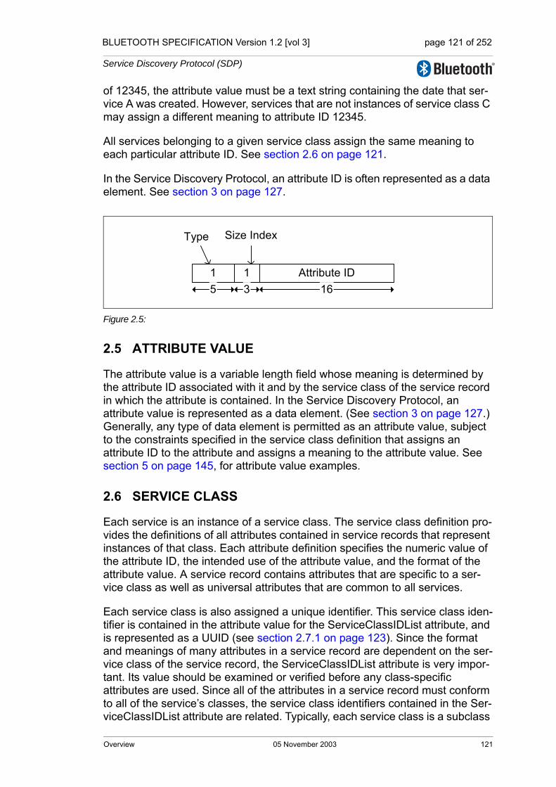
BLUETOOTH SPECIFICATION Version 1.2 [vol 3] page 121 of 252
Service Discovery Protocol (SDP)
of 12345, the attribute value must be a text string containing the date that ser-vice A was created. However, services that are not instances of service class C may assign a different meaning to attribute ID 12345.
All services belonging to a given service class assign the same meaning to each particular attribute ID. See section 2.6 on page 121.
In the Service Discovery Protocol, an attribute ID is often represented as a data element. See section 3 on page 127.
Figure 2.5:
2.5 ATTRIBUTE VALUE
The attribute value is a variable length field whose meaning is determined by the attribute ID associated with it and by the service class of the service record in which the attribute is contained. In the Service Discovery Protocol, an attribute value is represented as a data element. (See section 3 on page 127.) Generally, any type of data element is permitted as an attribute value, subject to the constraints specified in the service class definition that assigns an attribute ID to the attribute and assigns a meaning to the attribute value. See section 5 on page 145, for attribute value examples.
2.6 SERVICE CLASS
Each service is an instance of a service class. The service class definition pro-vides the definitions of all attributes contained in service records that represent instances of that class. Each attribute definition specifies the numeric value of the attribute ID, the intended use of the attribute value, and the format of the attribute value. A service record contains attributes that are specific to a ser-vice class as well as universal attributes that are common to all services.
Each service class is also assigned a unique identifier. This service class iden-tifier is contained in the attribute value for the ServiceClassIDList attribute, and is represented as a UUID (see section 2.7.1 on page 123). Since the format and meanings of many attributes in a service record are dependent on the ser-vice class of the service record, the ServiceClassIDList attribute is very impor-tant. Its value should be examined or verified before any class-specific attributes are used. Since all of the attributes in a service record must conform to all of the service’s classes, the service class identifiers contained in the Ser-viceClassIDList attribute are related. Typically, each service class is a subclass
1 1
Type
Attribute ID
Size Index
5 3 16
Overview 05 November 2003 121

BLUETOOTH SPECIFICATION Version 1.2 [vol 3] page 122 of 252
Service Discovery Protocol (SDP)
of another class whose identifier is contained in the list. A service subclass def-inition differs from its superclass in that the subclass contains additional attribute definitions that are specific to the subclass. The service class identifi-ers in the ServiceClassIDList attribute are listed in order from the most specific class to the most general class.
When a new service class is defined that is a subclass of an existing service class, the new service class retains all of the attributes defined in its super-class. Additional attributes will be defined that are specific to the new service class. In other words, the mechanism for adding new attributes to some of the instances of an existing service class is to create a new service class that is a subclass of the existing service class.
2.6.1 A Printer Service Class Example
A color postscript printer with duplex capability might conform to 4 Service-Class definitions and have a ServiceClassIDList with UUIDs (See section 2.7.1 on page 123.) representing the following ServiceClasses:
DuplexColorPostscriptPrinterServiceClassID,ColorPostscriptPrinterServiceClassID,PostscriptPrinterServiceClassID,PrinterServiceClassID
Note that this example is only illustrative. This may not be a practical printer class hierarchy.
122 05 November 2003 Overview

BLUETOOTH SPECIFICATION Version 1.2 [vol 3] page 123 of 252
Service Discovery Protocol (SDP)
2.7 SEARCHING FOR SERVICES
Once an SDP client has a service record handle, it may easily request the val-ues of specific attributes, but how does a client initially acquire a service record handle for the desired service records? The Service Search transaction allows a client to retrieve the service record handles for particular service records based on the values of attributes contained within those service records.
The capability search for service records based on the values of arbitrary attributes is not provided. Rather, the capability is provided to search only for attributes whose values are Universally Unique Identifiers1 (UUIDs). Important attributes of services that can be used to search for a service are represented as UUIDs.
2.7.1 UUID
A UUID is a universally unique identifier that is guaranteed to be unique across all space and all time. UUIDs can be independently created in a distributed fashion. No central registry of assigned UUIDs is required. A UUID is a 128-bit value.
To reduce the burden of storing and transferring 128-bit UUID values, a range of UUID values has been pre-allocated for assignment to often-used, regis-tered purposes. The first UUID in this pre-allocated range is known as the Bluetooth Base UUID and has the value 00000000-0000-1000-8000-00805F9B34FB, from the Bluetooth Assigned Numbers document. UUID val-ues in the pre-allocated range have aliases that are represented as 16-bit or 32-bit values. These aliases are often called 16-bit and 32-bit UUIDs, but it is important to note that each actually represents a 128-bit UUID value.
The full 128-bit value of a 16-bit or 32-bit UUID may be computed by a simple arithmetic operation.
128_bit_value = 16_bit_value * 296 + Bluetooth_Base_UUID
128_bit_value = 32_bit_value * 296 + Bluetooth_Base_UUID
A 16-bit UUID may be converted to 32-bit UUID format by zero-extending the 16-bit value to 32-bits. An equivalent method is to add the 16-bit UUID value to a zero-valued 32-bit UUID.
Note that two 16-bit UUIDs may be compared directly, as may two 32-bit UUIDs or two 128-bit UUIDs. If two UUIDs of differing sizes are to be com-
1. The format of UUIDs is defined by the International Organization for Standardization in ISO/IEC 11578:1996. “Information technology – Open Systems Interconnection – Remote Proce-dure Call (RPC)”
Overview 05 November 2003 123

BLUETOOTH SPECIFICATION Version 1.2 [vol 3] page 124 of 252
Service Discovery Protocol (SDP)
pared, the shorter UUID must be converted to the longer UUID format before comparison.
2.7.2 Service Search Patterns
A service search pattern is a list of UUIDs used to locate matching service records. A service search pattern is said to match a service record if each and every UUID in the service search pattern is contained within any of the service record’s attribute values. The UUIDs need not be contained within any specific attributes or in any particular order within the service record. The service search pattern matches if the UUIDs it contains constitute a subset of the UUIDs in the service record’s attribute values. The only time a service search pattern does not match a service record is if the service search pattern con-tains at least one UUID that is not contained within the service record’s attribute values. Note also that a valid service search pattern must contain at least one UUID.
2.8 BROWSING FOR SERVICES
Normally, a client searches for services based on some desired characteris-tic(s) (represented by a UUID) of the services. However, there are times when it is desirable to discover which types of services are described by an SDP server’s service records without any a priori information about the services. This process of looking for any offered services is termed browsing. In SDP, the mechanism for browsing for services is based on an attribute shared by all ser-vice classes. This attribute is called the BrowseGroupList attribute. The value of this attribute contains a list of UUIDs. Each UUID represents a browse group with which a service may be associated for the purpose of browsing.
When a client desires to browse an SDP server’s services, it creates a service search pattern containing the UUID that represents the root browse group. All services that may be browsed at the top level are made members of the root browse group by having the root browse group’s UUID as a value within the BrowseGroupList attribute.
Normally, if an SDP server has relatively few services, all of its services will be placed in the root browse group. However, the services offered by an SDP server may be organized in a browse group hierarchy, by defining additional browse groups below the root browse group. Each of these additional browse groups is described by a service record with a service class of BrowseGroupDescriptor.
A browse group descriptor service record defines a new browse group by means of its Group ID attribute. In order for a service contained in one of these newly defined browse groups to be browseable, the browse group descriptor service record that defines the new browse group must in turn be browseable. The hierarchy of browseable services that is provided by the use of browse group descriptor service records allows the services contained in an SDP
124 05 November 2003 Overview
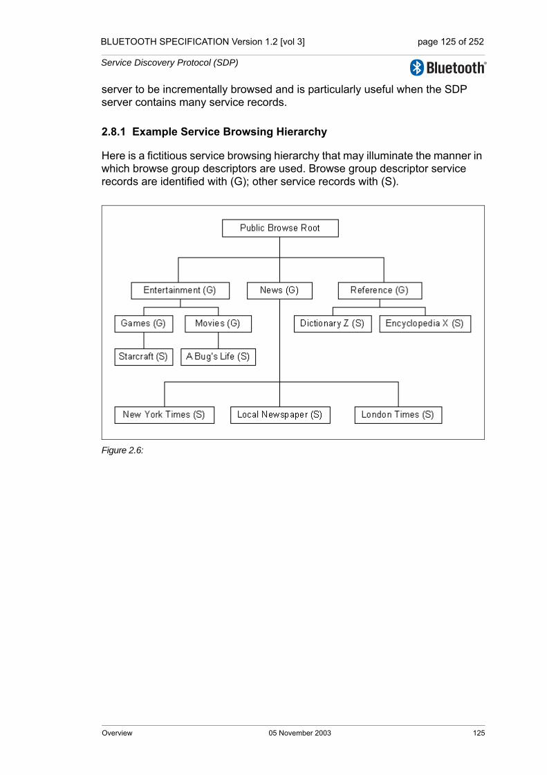
BLUETOOTH SPECIFICATION Version 1.2 [vol 3] page 125 of 252
Service Discovery Protocol (SDP)
server to be incrementally browsed and is particularly useful when the SDP server contains many service records.
2.8.1 Example Service Browsing Hierarchy
Here is a fictitious service browsing hierarchy that may illuminate the manner in which browse group descriptors are used. Browse group descriptor service records are identified with (G); other service records with (S).
Figure 2.6:
Overview 05 November 2003 125

BLUETOOTH SPECIFICATION Version 1.2 [vol 3] page 126 of 252
Service Discovery Protocol (SDP)
This table shows the services records and service attributes necessary to implement the browse hierarchy.
Service Name Service Class Attribute Name Attribute Value
Entertainment BrowseGroupDescriptor BrowseGroupList PublicBrowseRoot
GroupID EntertainmentID
News BrowsegroupDescriptor BrowseGroupList PublicBrowseRoot
GroupID NewsID
Reference BrowseGroupDescriptor BrowseGroupList PublicBrowseRoot
GroupID ReferenceID
Games BrowseGroupDescriptor BrowseGroupList EntertainmentID
GroupID GamesID
Movies BrowseGroupDescriptor BrowseGroupList EntertainmentID
GroupID MoviesID
Starcraft Video Game Class ID BrowseGroupList GamesID
A Bug’s Life Movie Class ID BrowseGroupList MovieID
Dictionary Z Dictionary Class ID BrowseGroupList ReferenceID
Encyclopedia X Encyclopedia Class ID BrowseGroupList ReferenceID
New York Times Newspaper ID BrowseGroupList NewspaperID
London Times Newspaper ID BrowseGroupList NewspaperID
Local Newspaper Newspaper ID BrowseGroupList NewspaperID
Table 2.1:
126 05 November 2003 Overview
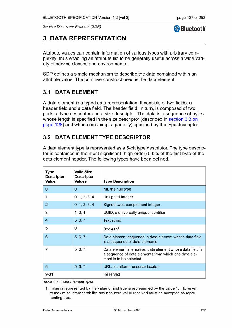
BLUETOOTH SPECIFICATION Version 1.2 [vol 3] page 127 of 252
Service Discovery Protocol (SDP)
3 DATA REPRESENTATION
Attribute values can contain information of various types with arbitrary com-plexity; thus enabling an attribute list to be generally useful across a wide vari-ety of service classes and environments.
SDP defines a simple mechanism to describe the data contained within an attribute value. The primitive construct used is the data element.
3.1 DATA ELEMENT
A data element is a typed data representation. It consists of two fields: a header field and a data field. The header field, in turn, is composed of two parts: a type descriptor and a size descriptor. The data is a sequence of bytes whose length is specified in the size descriptor (described in section 3.3 on page 128) and whose meaning is (partially) specified by the type descriptor.
3.2 DATA ELEMENT TYPE DESCRIPTOR
A data element type is represented as a 5-bit type descriptor. The type descrip-tor is contained in the most significant (high-order) 5 bits of the first byte of the data element header. The following types have been defined.
Type Descriptor Value
Valid Size Descriptor Values Type Description
0 0 Nil, the null type
1 0, 1, 2, 3, 4 Unsigned Integer
2 0, 1, 2, 3, 4 Signed twos-complement integer
3 1, 2, 4 UUID, a universally unique identifier
4 5, 6, 7 Text string
5 0 Boolean1
1. False is represented by the value 0, and true is represented by the value 1. However, to maximise interoperability, any non-zero value received must be accepted as repre-senting true.
6 5, 6, 7 Data element sequence, a data element whose data field is a sequence of data elements
7 5, 6, 7 Data element alternative, data element whose data field is a sequence of data elements from which one data ele-ment is to be selected.
8 5, 6, 7 URL, a uniform resource locator
9-31 Reserved
Table 3.1: Data Element Type.
Data Representation 05 November 2003 127

BLUETOOTH SPECIFICATION Version 1.2 [vol 3] page 128 of 252
Service Discovery Protocol (SDP)
3.3 DATA ELEMENT SIZE DESCRIPTOR
The data element size descriptor is represented as a 3-bit size index followed by 0, 8, 16, or 32 bits. The size index is contained in the least significant (low-order) 3 bits of the first byte of the data element header. The size index is encoded as follows.
Size Index
Additional bits Data Size
0 0 1 byte. Exception: if the data element type is nil, the data size is 0 bytes.
1 0 2 bytes
2 0 4 bytes
3 0 8 bytes
4 0 16 bytes
5 8 The data size is contained in the additional 8 bits, which are inter-preted as an unsigned integer.
6 16 The data size is contained in the additional 16 bits, which are interpreted as an unsigned integer.
7 32 The data size is contained in the additional 32 bits, which are interpreted as an unsigned integer.
Table 3.2:
128 05 November 2003 Data Representation
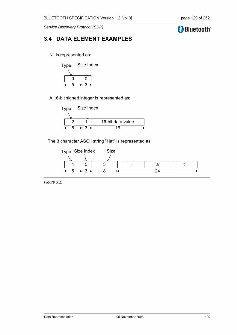
BLUETOOTH SPECIFICATION Version 1.2 [vol 3] page 129 of 252
Service Discovery Protocol (SDP)
3.4 DATA ELEMENT EXAMPLES
Figure 3.1:
0 0
Type
Nil is represented as:
2 1
Type
A 16-bit signed integer is represented as:
16-bit data value
The 3 character ASCII string "Hat" is represented as:
4 5
Type Size Index
Size Index
Size Index
3
Size
'H' 'a' 't'
5 3 16
5 3
5 3 8 24
Data Representation 05 November 2003 129

BLUETOOTH SPECIFICATION Version 1.2 [vol 3] page 130 of 252
Service Discovery Protocol (SDP)
130 05 November 2003 Data Representation
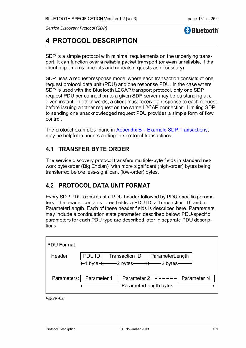
BLUETOOTH SPECIFICATION Version 1.2 [vol 3] page 131 of 252
Service Discovery Protocol (SDP)
4 PROTOCOL DESCRIPTION
SDP is a simple protocol with minimal requirements on the underlying trans-port. It can function over a reliable packet transport (or even unreliable, if the client implements timeouts and repeats requests as necessary).
SDP uses a request/response model where each transaction consists of one request protocol data unit (PDU) and one response PDU. In the case where SDP is used with the Bluetooth L2CAP transport protocol, only one SDP request PDU per connection to a given SDP server may be outstanding at a given instant. In other words, a client must receive a response to each request before issuing another request on the same L2CAP connection. Limiting SDP to sending one unacknowledged request PDU provides a simple form of flow control.
The protocol examples found in Appendix B – Example SDP Transactions, may be helpful in understanding the protocol transactions.
4.1 TRANSFER BYTE ORDER
The service discovery protocol transfers multiple-byte fields in standard net-work byte order (Big Endian), with more significant (high-order) bytes being transferred before less-significant (low-order) bytes.
4.2 PROTOCOL DATA UNIT FORMAT
Every SDP PDU consists of a PDU header followed by PDU-specific parame-ters. The header contains three fields: a PDU ID, a Transaction ID, and a ParameterLength. Each of these header fields is described here. Parameters may include a continuation state parameter, described below; PDU-specific parameters for each PDU type are described later in separate PDU descrip-tions.
Figure 4.1:
PDU Format:
Header:
Parameters:
PDU ID Transaction ID ParameterLength1 byte 2 bytes 2 bytes
Parameter 1 Parameter 2 Parameter NParameterLength bytes
Protocol Description 05 November 2003 131

BLUETOOTH SPECIFICATION Version 1.2 [vol 3] page 132 of 252
Service Discovery Protocol (SDP)
PDU ID: Size: 1 Byte
TransactionID: Size: 2 Bytes
ParameterLength: Size: 2 Bytes
Value Parameter Description
N The PDU ID field identifies the type of PDU. I.e. its meaning and the specific parameters.
0x00 Reserved
0x01 SDP_ErrorResponse
0x02 SDP_ServiceSearchRequest
0x03 SDP_ServiceSearchResponse
0x04 SDP_ServiceAttributeRequest
0x05 SDP_ServiceAttributeResponse
0x06 SDP_ServiceSearchAttributeRequest
0x07 SDP_ServiceSearchAttributeResponse
0x07-0xFF Reserved
Value Parameter Description
N The TransactionID field uniquely identifies request PDUs and is used to match response PDUs to request PDUs. The SDP client can choose any value for a request’s TransactionID provided that it is different from all outstanding requests. The TransactionID value in response PDUs is required to be the same as the request that is being responded to.Range: 0x0000 – 0xFFFF
Value Parameter Description
N The ParameterLength field specifies the length (in bytes) of all parame-ters contained in the PDU.Range: 0x0000 – 0xFFFF
132 05 November 2003 Protocol Description

BLUETOOTH SPECIFICATION Version 1.2 [vol 3] page 133 of 252
Service Discovery Protocol (SDP)
4.3 PARTIAL RESPONSES AND CONTINUATION STATE
Some SDP requests may require responses that are larger than can fit in a sin-gle response PDU. In this case, the SDP server will generate a partial response along with a continuation state parameter. The continuation state parameter can be supplied by the client in a subsequent request to retrieve the next portion of the complete response. The continuation state parameter is a variable length field whose first byte contains the number of additional bytes of continuation information in the field. The format of the continuation information is not standardized among SDP servers. Each continuation state parameter is meaningful only to the SDP server that generated it.
Figure 4.2: Continuation State Format
After a client receives a partial response and the accompanying continuation state parameter, it can re-issue the original request (with a new transaction ID) and include the continuation state in the new request indicating to the server that the remainder of the original response is desired. The maximum allowable value of the InfoLength field is 16 (0x10).
Note that an SDP server can split a response at any arbitrary boundary when it generates a partial response. The SDP server may select the boundary based on the contents of the reply, but is not required to do so.
4.4 ERROR HANDLING
Each transaction consists of a request and a response PDU. Generally, each type of request PDU has a corresponding type of response PDU. However, if the server determines that a request is improperly formatted or for any reason the server cannot respond with the appropriate PDU type, it will respond with an SDP_ErrorResponse PDU.
Figure 4.3:
InfoLength Continuation InformationInfoLength bytes1 byte
Any Request
SDP_ErrorResponseClient Server
Protocol Description 05 November 2003 133

BLUETOOTH SPECIFICATION Version 1.2 [vol 3] page 134 of 252
Service Discovery Protocol (SDP)
4.4.1 SDP_ErrorResponse PDU
Description:
The SDP server generates this PDU type in response to an improperly format-ted request PDU or when the SDP server, for whatever reason, cannot gener-ate an appropriate response PDU.
PDU Parameters:
ErrorCode: Size: 2 Bytes
ErrorInfo: Size: N Bytes
PDU Type PDU ID Parameters
SDP_ErrorResponse 0x01 ErrorCode,ErrorInfo
Value Parameter Description
N The ErrorCode identifies the reason that an SDP_ErrorResponse PDU was generated.
0x0000 Reserved
0x0001 Invalid/unsupported SDP version
0x0002 Invalid Service Record Handle
0x0003 Invalid request syntax
0x0004 Invalid PDU Size
0x0005 Invalid Continuation State
0x0006 Insufficient Resources to satisfy Request
0x0007-0xFFFF Reserved
Value Parameter Description
Error-specific ErrorInfo is an ErrorCode-specific parameter. Its interpretation depends on the ErrorCode parameter. The currently defined ErrorCode values do not specify the format of an ErrorInfo field.
134 05 November 2003 Protocol Description

BLUETOOTH SPECIFICATION Version 1.2 [vol 3] page 135 of 252
Service Discovery Protocol (SDP)
4.5 SERVICESEARCH TRANSACTION
Figure 4.4:
4.5.1 SDP_ServiceSearchRequest PDU
Description:
The SDP client generates an SDP_ServiceSearchRequest to locate service records that match the service search pattern given as the first parameter of the PDU. Upon receipt of this request, the SDP server will examine its service record data base and return an SDP_ServiceSearchResponse containing the service record handles of service records that match the given service search pattern.
Note that no mechanism is provided to request information for all service records. However, see section 2.8 on page 124 for a description of a mecha-nism that permits browsing for non-specific services without a priori knowledge of the services.
PDU Parameters:
ServiceSearchPattern: Size: Varies
PDU Type PDU ID Parameters
SDP_ServiceSearchRequest 0x02 ServiceSearchPattern,MaximumServiceRecordCount,ContinuationState
Value Parameter Description
Data Element Sequence
The ServiceSearchPattern is a data element sequence where each ele-ment in the sequence is a UUID. The sequence must contain at least one UUID. The maximum number of UUIDs in the sequence is 121. The list of UUIDs constitutes a service search pattern.
1. The value of 12 has been selected as a compromise between the scope of a service search and the size of a search request PDU. It is not expected that more than 12 UUIDs will be useful in a service search pattern.
SDP_ServiceSearchRequet
SDP_ServiceSearchResponClient Server
Protocol Description 05 November 2003 135
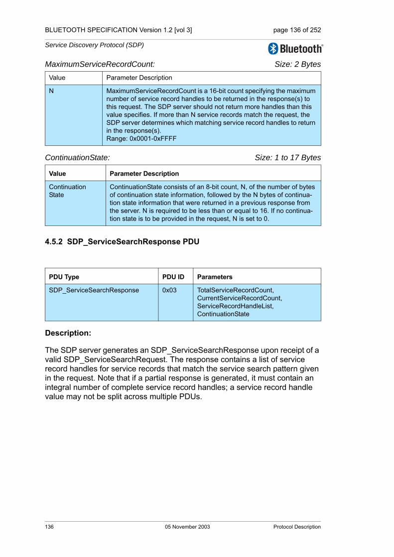
BLUETOOTH SPECIFICATION Version 1.2 [vol 3] page 136 of 252
Service Discovery Protocol (SDP)
MaximumServiceRecordCount: Size: 2 Bytes
ContinuationState: Size: 1 to 17 Bytes
4.5.2 SDP_ServiceSearchResponse PDU
Description:
The SDP server generates an SDP_ServiceSearchResponse upon receipt of a valid SDP_ServiceSearchRequest. The response contains a list of service record handles for service records that match the service search pattern given in the request. Note that if a partial response is generated, it must contain an integral number of complete service record handles; a service record handle value may not be split across multiple PDUs.
Value Parameter Description
N MaximumServiceRecordCount is a 16-bit count specifying the maximum number of service record handles to be returned in the response(s) to this request. The SDP server should not return more handles than this value specifies. If more than N service records match the request, the SDP server determines which matching service record handles to return in the response(s).Range: 0x0001-0xFFFF
Value Parameter Description
Continuation State
ContinuationState consists of an 8-bit count, N, of the number of bytes of continuation state information, followed by the N bytes of continua-tion state information that were returned in a previous response from the server. N is required to be less than or equal to 16. If no continua-tion state is to be provided in the request, N is set to 0.
PDU Type PDU ID Parameters
SDP_ServiceSearchResponse 0x03 TotalServiceRecordCount,CurrentServiceRecordCount,ServiceRecordHandleList,ContinuationState
136 05 November 2003 Protocol Description

BLUETOOTH SPECIFICATION Version 1.2 [vol 3] page 137 of 252
Service Discovery Protocol (SDP)
PDU Parameters:
TotalServiceRecordCount: Size: 2 Bytes
CurrentServiceRecordCount: Size: 2 Bytes
ServiceRecordHandleList: Size: (CurrentServiceRecordCount*4) Bytes
ContinuationState: Size: 1 to 17 Bytes
Value Parameter Description
N The TotalServiceRecordCount is an integer containing the number of service records that match the requested service search pattern. If no service records match the requested service search pattern, this param-eter is set to 0. N should never be larger than the MaximumServiceRe-cordCount value specified in the SDP_ServiceSearchRequest. When multiple partial responses are used, each partial response contains the same value for TotalServiceRecordCount.Range: 0x0000-0xFFFF
Value Parameter Description
N The CurrentServiceRecordCount is an integer indicating the number of service record handles that are contained in the next parameter. If no service records match the requested service search pattern, this param-eter is set to 0. N should never be larger than the TotalServiceRecord-Count value specified in the current response.Range: 0x0000-0xFFFF
Value Parameter Description
List of32-bit handles
The ServiceRecordHandleList contains a list of service record handles. The number of handles in the list is given in the CurrentServiceRecord-Count parameter. Each of the handles in the list refers to a service record that matches the requested service search pattern. Note that this list of service record handles does not have the format of a data ele-ment. It contains no header fields, only the 32-bit service record han-dles.
Value Parameter Description
Continuation State
ContinuationState consists of an 8-bit count, N, of the number of bytes of continuation state information, followed by the N bytes of continua-tion information. If the current response is complete, this parameter consists of a single byte with the value 0. If a partial response is con-tained in the PDU, the ContinuationState parameter may be supplied in a subsequent request to retrieve the remainder of the response.
Protocol Description 05 November 2003 137
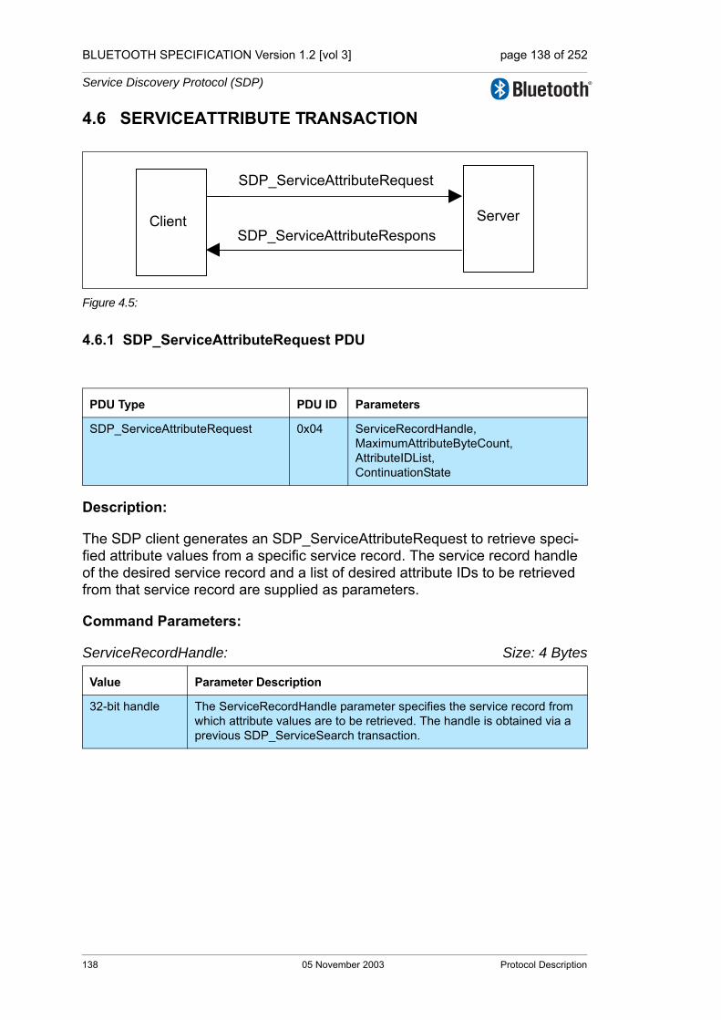
BLUETOOTH SPECIFICATION Version 1.2 [vol 3] page 138 of 252
Service Discovery Protocol (SDP)
4.6 SERVICEATTRIBUTE TRANSACTION
Figure 4.5:
4.6.1 SDP_ServiceAttributeRequest PDU
Description:
The SDP client generates an SDP_ServiceAttributeRequest to retrieve speci-fied attribute values from a specific service record. The service record handle of the desired service record and a list of desired attribute IDs to be retrieved from that service record are supplied as parameters.
Command Parameters:
ServiceRecordHandle: Size: 4 Bytes
PDU Type PDU ID Parameters
SDP_ServiceAttributeRequest 0x04 ServiceRecordHandle,MaximumAttributeByteCount,AttributeIDList,ContinuationState
Value Parameter Description
32-bit handle The ServiceRecordHandle parameter specifies the service record from which attribute values are to be retrieved. The handle is obtained via a previous SDP_ServiceSearch transaction.
SDP_ServiceAttributeRequest
SDP_ServiceAttributeResponsClient Server
138 05 November 2003 Protocol Description

BLUETOOTH SPECIFICATION Version 1.2 [vol 3] page 139 of 252
Service Discovery Protocol (SDP)
MaximumAttributeByteCount: Size: 2 Bytes
AttributeIDList: Size: Varies
ContinuationState: Size: 1 to 17 Bytes
Value Parameter Description
N MaximumAttributeByteCount specifies the maximum number of bytes of attribute data to be returned in the response to this request. The SDP server should not return more than N bytes of attribute data in the response PDU. If the requested attributes require more than N bytes, the SDP server determines how to segment the list. In this case the cli-ent may request each successive segment by issuing a request contain-ing the continuation state that was returned in the previous response PDU. Note that in the case where multiple response PDUs are needed to return the attribute data, MaximumAttributeByteCount specifies the maximum size of the portion of the attribute data contained in each response PDU.Range: 0x0007-0xFFFF
Value Parameter Description
Data Element Sequence
The AttributeIDList is a data element sequence where each element in the list is either an attribute ID or a range of attribute IDs. Each attribute ID is encoded as a 16-bit unsigned integer data element. Each attribute ID range is encoded as a 32-bit unsigned integer data element, where the high order 16 bits are interpreted as the beginning attribute ID of the range and the low order 16 bits are interpreted as the ending attribute ID of the range. The attribute IDs contained in the AttributeIDList must be listed in ascending order without duplication of any attribute ID values. Note that all attributes may be requested by specifying a range of 0x0000-0xFFFF.
Value Parameter Description
Continuation State
ContinuationState consists of an 8-bit count, N, of the number of bytes of continuation state information, followed by the N bytes of continua-tion state information that were returned in a previous response from the server. N is required to be less than or equal to 16. If no continua-tion state is to be provided in the request, N is set to 0.
Protocol Description 05 November 2003 139
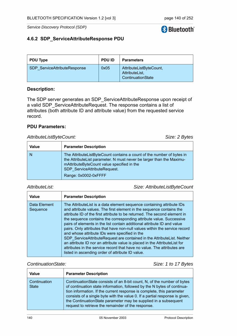
BLUETOOTH SPECIFICATION Version 1.2 [vol 3] page 140 of 252
Service Discovery Protocol (SDP)
4.6.2 SDP_ServiceAttributeResponse PDU
Description:
The SDP server generates an SDP_ServiceAttributeResponse upon receipt of a valid SDP_ServiceAttributeRequest. The response contains a list of attributes (both attribute ID and attribute value) from the requested service record.
PDU Parameters:
AttributeListByteCount: Size: 2 Bytes
AttributeList: Size: AttributeListByteCount
ContinuationState: Size: 1 to 17 Bytes
PDU Type PDU ID Parameters
SDP_ServiceAttributeResponse 0x05 AttributeListByteCount,AttributeList,ContinuationState
Value Parameter Description
N The AttributeListByteCount contains a count of the number of bytes in the AttributeList parameter. N must never be larger than the Maximu-mAttributeByteCount value specified in the SDP_ServiceAttributeRequest.Range: 0x0002-0xFFFF
Value Parameter Description
Data Element Sequence
The AttributeList is a data element sequence containing attribute IDs and attribute values. The first element in the sequence contains the attribute ID of the first attribute to be returned. The second element in the sequence contains the corresponding attribute value. Successive pairs of elements in the list contain additional attribute ID and value pairs. Only attributes that have non-null values within the service record and whose attribute IDs were specified in the SDP_ServiceAttributeRequest are contained in the AttributeList. Neither an attribute ID nor an attribute value is placed in the AttributeList for attributes in the service record that have no value. The attributes are listed in ascending order of attribute ID value.
Value Parameter Description
Continuation State
ContinuationState consists of an 8-bit count, N, of the number of bytes of continuation state information, followed by the N bytes of continua-tion information. If the current response is complete, this parameter consists of a single byte with the value 0. If a partial response is given, the ContinuationState parameter may be supplied in a subsequent request to retrieve the remainder of the response.
140 05 November 2003 Protocol Description

BLUETOOTH SPECIFICATION Version 1.2 [vol 3] page 141 of 252
Service Discovery Protocol (SDP)
4.7 SERVICESEARCHATTRIBUTE TRANSACTION
Figure 4.6:
4.7.1 SDP_ServiceSearchAttributeRequest PDU
Description:
The SDP_ServiceSearchAttributeRequest transaction combines the capabili-ties of the SDP_ServiceSearchRequest and the SDP_ServiceAttributeRequest into a single request. As parameters, it contains both a service search pattern and a list of attributes to be retrieved from service records that match the ser-vice search pattern. The SDP_ServiceSearchAttributeRequest and its response are more complex and may require more bytes than separate SDP_ServiceSearch and SDP_ServiceAttribute transactions. However, using SDP_ServiceSearchAttributeRequest may reduce the total number of SDP transactions, particularly when retrieving multiple service records.
Note that the service record handle for each service record is contained in the ServiceRecordHandle attribute of that service and may be requested along with other attributes.
PDU Parameters:
ServiceSearchPattern: Size: Varies
PDU Type PDU ID Parameters
SDP_ServiceSearchAttributeRequest 0x06 ServiceSearchPattern,MaximumAttributeByteCount,AttributeIDList,ContinuationState
Value Parameter Description
Data Element Sequence
The ServiceSearchPattern is a data element sequence where each ele-ment in the sequence is a UUID. The sequence must contain at leastone UUID. The maximum number of UUIDs in the sequence is 121. The list of UUIDs constitutes a service search pattern.
1. The value of 12 has been selected as a compromise between the scope of a service search and the size of a search request PDU. It is not expected that more than 12 UUIDs will be useful in a service search pattern.
SDP_ServiceSearchAttributeRequest
SDP_ServiceSearchAttributeResponseClient Server
Protocol Description 05 November 2003 141
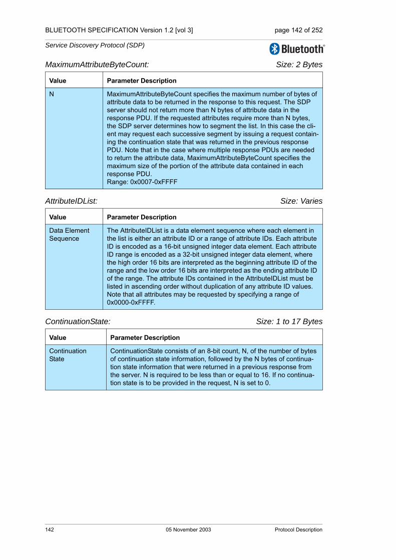
BLUETOOTH SPECIFICATION Version 1.2 [vol 3] page 142 of 252
Service Discovery Protocol (SDP)
MaximumAttributeByteCount: Size: 2 Bytes
AttributeIDList: Size: Varies
ContinuationState: Size: 1 to 17 Bytes
Value Parameter Description
N MaximumAttributeByteCount specifies the maximum number of bytes of attribute data to be returned in the response to this request. The SDP server should not return more than N bytes of attribute data in the response PDU. If the requested attributes require more than N bytes, the SDP server determines how to segment the list. In this case the cli-ent may request each successive segment by issuing a request contain-ing the continuation state that was returned in the previous response PDU. Note that in the case where multiple response PDUs are needed to return the attribute data, MaximumAttributeByteCount specifies the maximum size of the portion of the attribute data contained in each response PDU.Range: 0x0007-0xFFFF
Value Parameter Description
Data Element Sequence
The AttributeIDList is a data element sequence where each element in the list is either an attribute ID or a range of attribute IDs. Each attribute ID is encoded as a 16-bit unsigned integer data element. Each attribute ID range is encoded as a 32-bit unsigned integer data element, where the high order 16 bits are interpreted as the beginning attribute ID of the range and the low order 16 bits are interpreted as the ending attribute ID of the range. The attribute IDs contained in the AttributeIDList must be listed in ascending order without duplication of any attribute ID values. Note that all attributes may be requested by specifying a range of 0x0000-0xFFFF.
Value Parameter Description
Continuation State
ContinuationState consists of an 8-bit count, N, of the number of bytes of continuation state information, followed by the N bytes of continua-tion state information that were returned in a previous response from the server. N is required to be less than or equal to 16. If no continua-tion state is to be provided in the request, N is set to 0.
142 05 November 2003 Protocol Description
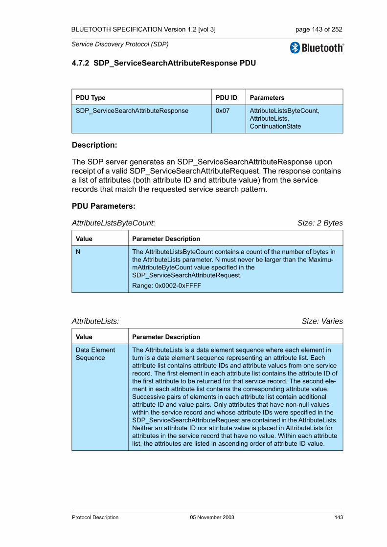
BLUETOOTH SPECIFICATION Version 1.2 [vol 3] page 143 of 252
Service Discovery Protocol (SDP)
4.7.2 SDP_ServiceSearchAttributeResponse PDU
Description:
The SDP server generates an SDP_ServiceSearchAttributeResponse upon receipt of a valid SDP_ServiceSearchAttributeRequest. The response contains a list of attributes (both attribute ID and attribute value) from the service records that match the requested service search pattern.
PDU Parameters:
AttributeListsByteCount: Size: 2 Bytes
AttributeLists: Size: Varies
PDU Type PDU ID Parameters
SDP_ServiceSearchAttributeResponse 0x07 AttributeListsByteCount,AttributeLists,ContinuationState
Value Parameter Description
N The AttributeListsByteCount contains a count of the number of bytes in the AttributeLists parameter. N must never be larger than the Maximu-mAttributeByteCount value specified in the SDP_ServiceSearchAttributeRequest.Range: 0x0002-0xFFFF
Value Parameter Description
Data Element Sequence
The AttributeLists is a data element sequence where each element in turn is a data element sequence representing an attribute list. Each attribute list contains attribute IDs and attribute values from one service record. The first element in each attribute list contains the attribute ID of the first attribute to be returned for that service record. The second ele-ment in each attribute list contains the corresponding attribute value. Successive pairs of elements in each attribute list contain additional attribute ID and value pairs. Only attributes that have non-null values within the service record and whose attribute IDs were specified in the SDP_ServiceSearchAttributeRequest are contained in the AttributeLists. Neither an attribute ID nor attribute value is placed in AttributeLists for attributes in the service record that have no value. Within each attribute list, the attributes are listed in ascending order of attribute ID value.
Protocol Description 05 November 2003 143