Embed Size (px)
Citation preview
1
Master Sync / Master Clock Reference Generator SPG8000A datasheet
The SPG8000A is a precision multiformat video signal generator, suitable for master synchronization and reference applications. It provides multiple video reference signals, such as black burst, HD tri-level sync, and serial digital and composite analog test patterns, and it provides time reference signals such as time code, NTP (Network Time Protocol), and IEEE 1588 PTP (Precision Time Protocol).
Key features
Multiple independent black burst and HD tri-level sync outputs provide all the video reference signals required in a video broadcast or production facility
Four LTC outputs, VITC on black burst outputs, and NTP server provide time reference signals in a variety of formats
PTP (IEEE 1588) support, including SMPTE ST 2059-2 and AES67 profiles
GPS/GLONASS-based synchronization gives an accurate time-of-day reference and deterministic video phase reference across multiple independent systems
Stay GenLock® and Holdover Recovery prevent synchronization shock when the external reference input, PTP, or GPS/GLONASS signal is temporarily lost
Wide selection of video test patterns in serial digital formats (SD, HD and 3G-SDI) and composite analog formats (NTSC and PAL)
4K/UHD formats support with full frame 100% and 75% color bars (Quad Link Square Division)
Dual hot-swappable power supplies ensure continuous availability of reference signals
Easy to manage with Web-based interface for remote configuration and SNMP for status and alert information
Applications
Sync generator and time reference generator for broadcast, studio, mobile, and post-production facilities
Master or slave (genlock) operation for distributed system architectures
Video equipment verification, facility link testing, and display calibration
Master video synchronization and time reference generator The base configuration includes three sync outputs that can be configured with independent output formats and independently adjustable timing offsets. With Option BG, four more analog outputs can be added. A high- accuracy, oven-controlled crystal oscillator provides a stable frequency reference for the system, or the pass-through genlock input can be used to lock to an external video reference or 10 MHz continuous wave signal.
The SPG8000A’s Stay GenLock® feature avoids “synchronization shock” if the external reference suffers a temporary disturbance, by maintaining the frequency and phase of each output signal. When the external reference is restored, Stay GenLock® ensures that any accumulated clock drift is removed by slowly adjusting the system clock within standard limits instead of “jamming” back to the correct phase.
2
SPG8000A Datasheet
Time reference outputs are available in multiple formats. Three independent linear time code (LTC) outputs are available, and a fourth LTC connection can be used as input or output. Each LTC output has independent frame rate selection, time source (time-of-day or program time) and time zone offset. Vertical interval time code (VITC) is available on each NTSC or PAL black output, also with independent time sources and offsets. The SPG8000A can also serve as a Network Time Protocol (NTP) server or as a Precision Time Protocol (PTP) grandmaster clock, providing the time-of-day reference to network-attached devices.
Optional GPS / GLONASS receiver Option GPS adds an integrated receiver to the SPG8000A that is capable of receiving both GPS and GLONASS signals. When connected to an external antenna that supplies the standard GPS and/or GLONASS RF signal (for example, SPG8000ANT), the SPG8000A can use the GPS/GLONASS system’s stable frequency reference.
The GPS/GLONASS signal also includes a precise time-of-day reference that can be used for all time code outputs. Similar to the Stay GenLock® feature, the SPG8000A can maintain the video frequency and phase when the GPS/GLONASS signal is interrupted, and the Holdover Recovery mode will ensure a shock-free realignment of frequency and phase when the GPS/GLONASS signal is restored.
Optional PTP support Option PTP adds two Precision Time Protocol (PTP) engines to the SPG system. The primary PTP engine has the capability to be a master PTP source or lock the SPG to the PTP as a slave. The secondary PTP engine can only be a master. The secondary engine allows implementing two masters when in Internal mode or locked to GPS, and simultaneous Master and Slave operation.
The black outputs support a 1pps mode. This is useful for measuring timing between systems.
Test signal outputs The SPG8000A can be optionally configured with a variety of test signal outputs. Option BG includes two composite analog outputs (NTSC or PAL) that can be used to generate test patterns such as color bars, or serve as additional black burst outputs.
Option SDI adds two fully independent serial digital video generator channels of two outputs each. Each channel can be configured to any standard 3G/HD/SD-SDI format and frame rate. The selected test pattern can be generated on both outputs per channel, or one output can generate digital black.
A wide variety of standard test patterns are included, such as color bars, convergence grid, step scales, ramps, multiburst, SDI pathological test matrix and a real-time programmable zone plate generator. Bitmap images can be downloaded to the SPG8000A’s flash memory for arbitrary user- defined test patterns. ID text, burn-in time code, circle, and color logo overlays can be added to any test pattern, and several ancillary data packet types, including ancillary time code and user-defined packets, can be inserted into the SDI output signal.
The four SDI outputs can be configured to support 4K/UHD full frame, 100% and 75% color bars for quad link square division mode. This allows simple verification of your 4K/UHD workflow within the production studio or mobile truck. Note: VPIDs are compliant only to HD and 3G formats in 4K/ UHD formats.
Also included is an audio/video delay test sequence, which in conjunction with a Telestream waveform monitor, can be used to ensure A/V delay compliance.
Audio reference signals Several audio reference signals are available on the SPG8000A. The base configuration includes a 48 kHz word clock output, and Option AG adds five AES/EBU output pairs. One pair is dedicated to a Digital Audio Reference Signal (DARS) output, and the other four pairs are used for test tone generation, with independent tone frequency and amplitude settings for each of the 8 channels.
Audio tone generation, including Dolby E format, is provided with Option SDI as embedded audio on each of the SDI outputs. Various Dolby E audio frame start locations can be set to test the error handling ability of the signal processing equipment in the signal path. Embedded Dolby E metadata are also included in the Dolby E test stream. Supported Dolby E program configurations include mono, stereo, 5.1 and 7.1 surround sound audio.
Remote access The SPG8000A includes a 10/100/1000BASE-T Ethernet interface for remote access to the instrument. A web-based user interface can be used for all configuration settings and for monitoring system status.
Alarm and key status information is also available using Simple Network Management Protocol (SNMP) messaging, enabling easy integration with network management systems. Remote control and alarm reporting is also available using a general purpose interface (GPI). The SPG8000A has a front-panel USB port that can be used to backup and restore presets and other user data, and to perform system firmware upgrades.

SPG8000A Datasheet
3
Optional backup power supply For mission-critical applications, the SPG8000A can be configured with a second power supply module. Under normal operation, the designated backup supply is seldom used, ensuring that it has maximum remaining life should the primary supply fail. The backup supply is load-tested once each day to verify that it can serve as the primary supply if necessary.
The usage time of each supply is logged as “temperature-weighted hours”, a metric that best estimates the calculated life of the supply. A front-panel LED will indicate when the supply is nearing its end-of-life.
If the primary supply is interrupted for any reason, the system will switch to the backup without any disruption to system operation. Power supply modules are hot-swappable for easy replacement, and feature a locking mechanism to prevent the power cable from accidental disconnection.
SPG8000A Datasheet
4
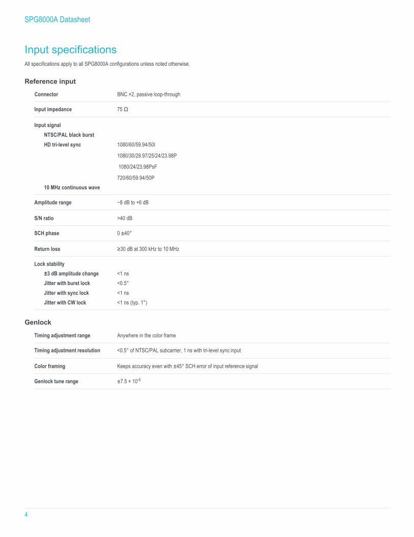
Input specifications All specifications apply to all SPG8000A configurations unless noted otherwise.
Reference input
Connector BNC ×2, passive loop-through
Input impedance 75 Ω
Input signal NTSC/PAL black burst HD tri-level sync 1080/60/59.94/50I
1080/30/29.97/25/24/23.98P
1080/24/23.98PsF
720/60/59.94/50P 10 MHz continuous wave
Amplitude range −8 dB to +6 dB
S/N ratio >40 dB
SCH phase 0 ±40°
Return loss ≥30 dB at 300 kHz to 10 MHz
Lock stability ±3 dB amplitude change <1 ns Jitter with burst lock <0.5° Jitter with sync lock <1 ns Jitter with CW lock <1 ns (typ. 1°)
Genlock
Timing adjustment range Anywhere in the color frame
Timing adjustment resolution <0.5° of NTSC/PAL subcarrier, 1 ns with tri-level sync input
Color framing Keeps accuracy even with ±45° SCH error of input reference signal
Genlock tune range ±7.5 × 10⁻⁶
SPG8000A Datasheet
5
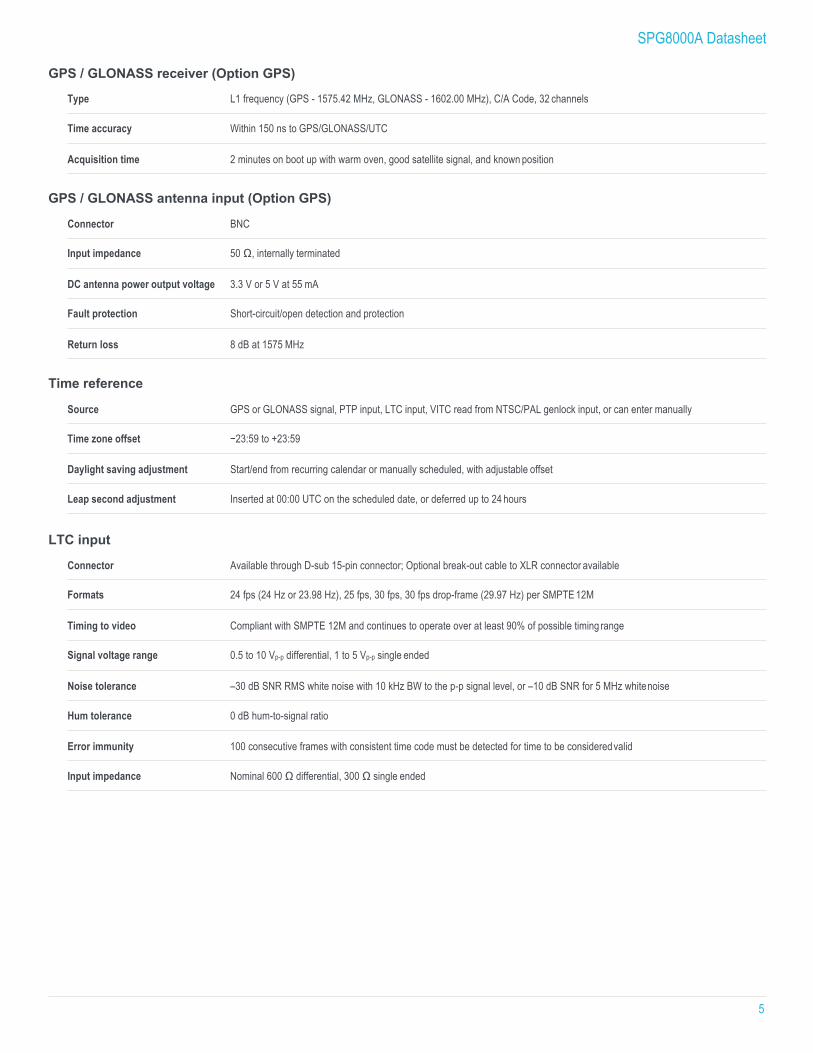
GPS / GLONASS receiver (Option GPS)
Type L1 frequency (GPS - 1575.42 MHz, GLONASS - 1602.00 MHz), C/A Code, 32 channels
Time accuracy Within 150 ns to GPS/GLONASS/UTC
Acquisition time 2 minutes on boot up with warm oven, good satellite signal, and known position
GPS / GLONASS antenna input (Option GPS)
Connector BNC
Input impedance 50 Ω, internally terminated
DC antenna power output voltage 3.3 V or 5 V at 55 mA
Fault protection Short-circuit/open detection and protection
Return loss 8 dB at 1575 MHz
Time reference
Source GPS or GLONASS signal, PTP input, LTC input, VITC read from NTSC/PAL genlock input, or can enter manually
Time zone offset −23:59 to +23:59
Daylight saving adjustment Start/end from recurring calendar or manually scheduled, with adjustable offset
Leap second adjustment Inserted at 00:00 UTC on the scheduled date, or deferred up to 24 hours
LTC input
Connector Available through D-sub 15-pin connector; Optional break-out cable to XLR connector available
Formats 24 fps (24 Hz or 23.98 Hz), 25 fps, 30 fps, 30 fps drop-frame (29.97 Hz) per SMPTE 12M
Timing to video Compliant with SMPTE 12M and continues to operate over at least 90% of possible timing range
Signal voltage range 0.5 to 10 Vp-p differential, 1 to 5 Vp-p single ended
Noise tolerance –30 dB SNR RMS white noise with 10 kHz BW to the p-p signal level, or –10 dB SNR for 5 MHz white noise
Hum tolerance 0 dB hum-to-signal ratio
Error immunity 100 consecutive frames with consistent time code must be detected for time to be considered valid
Input impedance Nominal 600 Ω differential, 300 Ω single ended
SPG8000A Datasheet
6
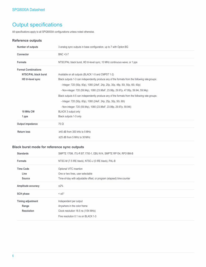
Output specifications All specifications apply to all SPG8000A configurations unless noted otherwise.
Reference outputs
Number of outputs 3 analog sync outputs in base configuration, up to 7 with Option BG
Connector BNC ×3-7
Formats NTSC/PAL black burst, HD tri-level sync, 10 MHz continuous wave, or 1 pps
Format Combinations NTSC/PAL black burst Available on all outputs (BLACK 1-5 and CMPST 1-2) HD tri-level sync Black outputs 1-3 can independently produce any of the formats from the following rate groups:
- Integer: 720 (50p, 60p), 1080 (24sF, 24p, 25p, 30p, 48p, 50i, 50p, 60i, 60p)
- Non-integer: 720 (59.94p), 1080 (23.98sF, 23.98p, 29.97p, 47.95p, 59.94i, 59.94p)
Black outputs 4-5 can independently produce any of the formats from the following rate groups:
- Integer: 720 (50p, 60p), 1080 (24sF, 24p, 25p, 30p, 50i, 60i)
- Non-integer: 720 (59.94p), 1080 (23.98sF, 23.98p, 29.97p, 59.94i) 10 MHz CW BLACK 3 output only 1 pps Black outputs 1-3 only
Output impedance 75 Ω
Return loss ≥40 dB from 300 kHz to 5 MHz
≥25 dB from 5 MHz to 30 MHz
Black burst mode for reference sync outputs
Standards SMPTE 170M, ITU-R BT.1700-1, EBU N14, SMPTE RP154, RP318M-B
Formats NTSC-M (7.5 IRE black), NTSC-J (0 IRE black), PAL-B
Time Code Optional VITC insertion Line One or two lines, user selectable Source Time-of-day with adjustable offset, or program (elapsed) time counter
Amplitude accuracy ±2%
SCH phase < ±5°
Timing adjustment Independent per output Range Anywhere in the color frame Resolution Clock resolution 18.5 ns (1/54 MHz)
Fine resolution 0.1 ns on BLACK 1-3
SPG8000A Datasheet
7
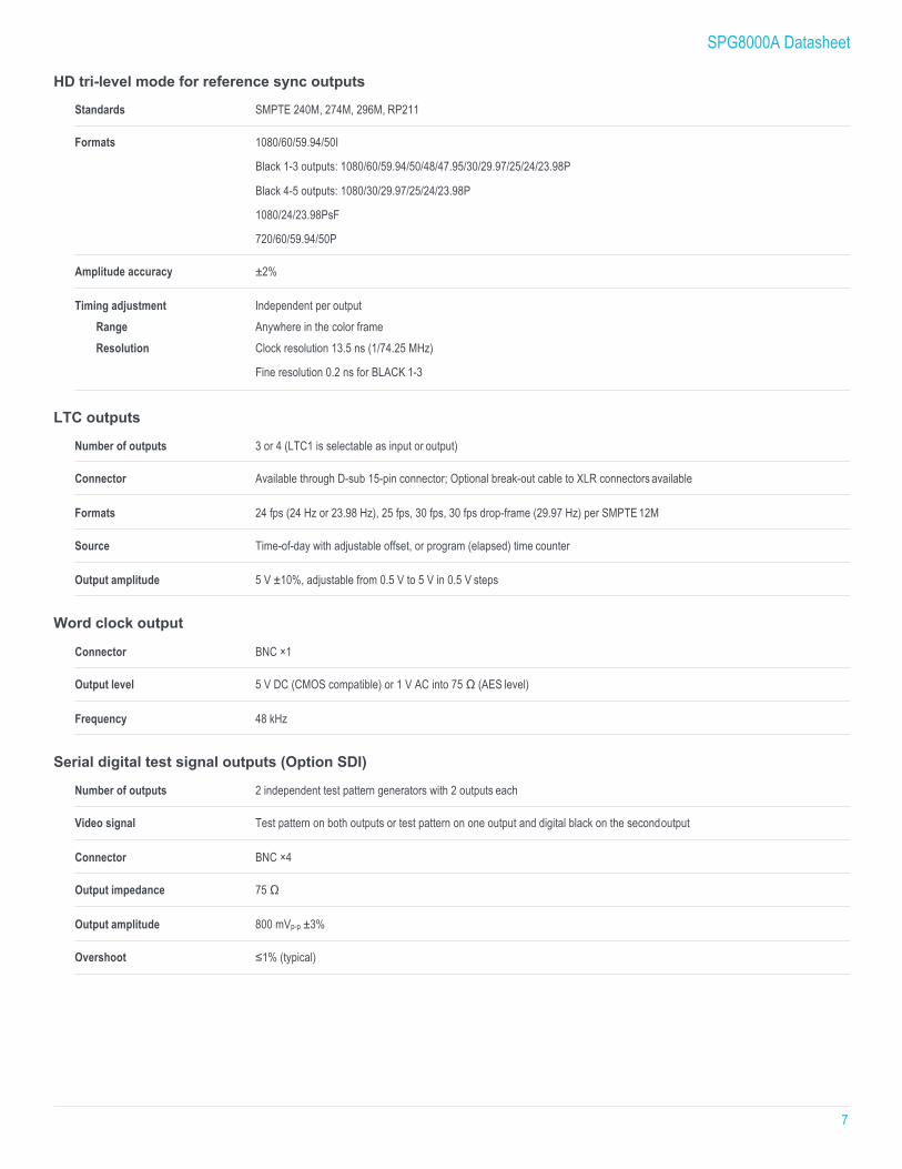
HD tri-level mode for reference sync outputs
Standards SMPTE 240M, 274M, 296M, RP211
Formats 1080/60/59.94/50I
Black 1-3 outputs: 1080/60/59.94/50/48/47.95/30/29.97/25/24/23.98P
Black 4-5 outputs: 1080/30/29.97/25/24/23.98P
1080/24/23.98PsF
720/60/59.94/50P
Amplitude accuracy ±2%
Timing adjustment Independent per output Range Anywhere in the color frame Resolution Clock resolution 13.5 ns (1/74.25 MHz)
Fine resolution 0.2 ns for BLACK 1-3
LTC outputs
Number of outputs 3 or 4 (LTC1 is selectable as input or output)
Connector Available through D-sub 15-pin connector; Optional break-out cable to XLR connectors available
Formats 24 fps (24 Hz or 23.98 Hz), 25 fps, 30 fps, 30 fps drop-frame (29.97 Hz) per SMPTE 12M
Source Time-of-day with adjustable offset, or program (elapsed) time counter
Output amplitude 5 V ±10%, adjustable from 0.5 V to 5 V in 0.5 V steps
Word clock output
Connector BNC ×1
Output level 5 V DC (CMOS compatible) or 1 V AC into 75 Ω (AES level)
Frequency 48 kHz
Serial digital test signal outputs (Option SDI)
Number of outputs 2 independent test pattern generators with 2 outputs each
Video signal Test pattern on both outputs or test pattern on one output and digital black on the second output
Connector BNC ×4
Output impedance 75 Ω
Output amplitude 800 mVp-p ±3%
Overshoot ≤1% (typical)
SPG8000A Datasheet
8
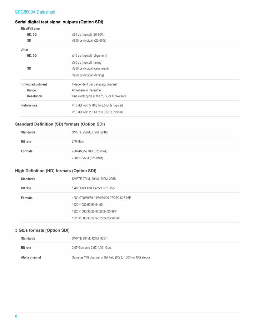
Serial digital test signal outputs (Option SDI) Rise/Fall time
HD, 3G ≤70 ps (typical) (20-80%) SD ≤700 ps (typical) (20-80%)
Jitter HD, 3G ≤40 ps (typical) (alignment)
≤80 ps (typical) (timing) SD ≤200 ps (typical) (alignment)
≤200 ps (typical) (timing)
Timing adjustment Independent per generator channel Range Anywhere in the frame Resolution One clock cycle at the Y, G, or X pixel rate
Return loss ≥15 dB from 5 MHz to 2.5 GHz (typical)
≥10 dB from 2.5 GHz to 3 GHz (typical)
Standard Definition (SD) formats (Option SDI)
Standards SMPTE 259M, 272M, 291M
Bit rate 270 Mb/s
Formats 720×486/59.94/I (525 lines)
720×576/50/I (625 lines)
High Definition (HD) formats (Option SDI)
Standards SMPTE 274M, 291M, 292M, 296M
Bit rate 1.485 Gb/s and 1.485/1.001 Gb/s
Formats 1280×720/60/59.94/50/30/29.97/25/24/23.98P
1920×1080/60/59.94/50I
1920×1080/30/29.97/25/24/23.98P
1920×1080/30/29.97/25/24/23.98PsF
3 Gb/s formats (Option SDI)
Standards SMPTE 291M, 424M, 425-1
Bit rate 2.97 Gb/s and 2.97/1.001 Gb/s
Alpha channel Same as Y/G channel or flat field (0% to 100% in 10% steps)
SPG8000A Datasheet
9
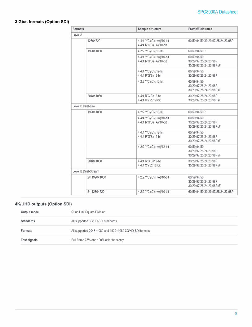
3 Gb/s formats (Option SDI)
Formats Sample structure Frame/Field rates Level A
1280×720 4:4:4 Y'C'BC'R(+A)/10-bit 4:4:4 R’G’B’(+A)/10-bit
60/59.94/50/30/29.97/25/24/23.98P
1920×1080 4:2:2 Y'C'BC'R/10-bit 60/59.94/50P 4:4:4 Y'C'BC'R(+A)/10-bit 4:4:4 R’G’B’(+A)/10-bit
60/59.94/50I 30/29.97/25/24/23.98P 30/29.97/25/24/23.98PsF
4:4:4 Y'C'BC'R/12-bit 4:4:4 R’G’B’/12-bit
60/59.94/50I 30/29.97/25/24/23.98P
4:2:2 Y'C'BC'R/12-bit 60/59.94/50I 30/29.97/25/24/23.98P 30/29.97/25/24/23.98PsF
2048×1080 4:4:4 R’G’B’/12-bit 4:4:4 X’Y’Z’/12-bit
30/29.97/25/24/23.98P 30/29.97/25/24/23.98PsF
Level B Dual-Link 1920×1080 4:2:2 Y'C'BC'R/10-bit 60/59.94/50P
4:4:4 Y'C'BC'R(+A)/10-bit 4:4:4 R’G’B’(+A)/10-bit
60/59.94/50I 30/29.97/25/24/23.98P 30/29.97/25/24/23.98PsF
4:4:4 Y'C'BC'R/12-bit 4:4:4 R’G’B’/12-bit
60/59.94/50I 30/29.97/25/24/23.98P 30/29.97/25/24/23.98PsF
4:2:2 Y'C'BC'R(+A)/12-bit 60/59.94/50I 30/29.97/25/24/23.98P 30/29.97/25/24/23.98PsF
2048×1080 4:4:4 R’G’B’/12-bit 4:4:4 X’Y’Z’/12-bit
30/29.97/25/24/23.98P 30/29.97/25/24/23.98PsF
Level B Dual-Stream 2× 1920×1080 4:2:2 Y'C'BC'R(+A)/10-bit 60/59.94/50I
30/29.97/25/24/23.98P 30/29.97/25/24/23.98PsF
2× 1280×720 4:2:2 Y'C'BC'R(+A)/10-bit 60/59.94/50/30/29.97/25/24/23.98P
4K/UHD outputs (Option SDI)
Output mode Quad Link Square Division
Standards All supported 3G/HD-SDI standards
Formats All supported 2048×1080 and 1920×1080 3G/HD-SDI formats
Test signals Full frame 75% and 100% color bars only
SPG8000A Datasheet
10
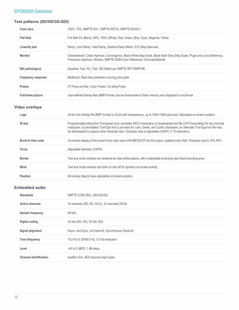
Test patterns (SD/HD/3G-SDI)
Color bars 100%, 75%, SMPTE EG1, SMPTE RP219, SMPTE EG432-1
Flat field Full field 0% (Black), 50%, 100% (White), Red, Green, Blue, Cyan, Magenta, Yellow
Linearity test Ramp, Limit Ramp, Valid Ramp, Shallow Ramp Matrix, 5/10 Step Staircase
Monitor Checkerboard, Clean Aperture, Convergence, Black-White Step Scale, Black-Dark Gray Step Scale, Pluge and Luma Reference, Production Aperture, Window, SMPTE 303M Color Reference, ChromaDuMonde
SDI pathological Equalizer Test, PLL Test, SDI Matrix per SMPTE RP178/RP198
Frequency response Multiburst, Real-time parametric moving zone plate
Pulses 2T Pulse and Bar, Color Pulses, Co-siting Pulse
Full-frame picture User-defined bitmap files (BMP format) can be downloaded to flash memory and displayed in any format
Video overlays
Logo 24-bit color bitmap file (BMP format) or 32-bit with transparency, up to 1920×1080 pixel size. Adjustable on-screen position.
ID text Programmable string from front-panel entry (printable ASCII characters) or downloaded text file (UTF-8 encoding) for any Unicode characters. A preinstalled TrueType font is provided for Latin, Greek, and Cyrillic characters; an alternate TrueType font file may be downloaded to support other character sets. Character size is adjustable (%APH, 0.1% resolution).
Burnt-in time code On-screen display of the current time code value (HH:MM:SS:FF) for the output, updated every field. Character size is 10% APH.
Circle Adjustable diameter (%APH).
Border Text and circle overlays are rendered as near-white objects, with a selectable enclosing near-black bounding area.
Blink Text and circle overlays can blink on and off for dynamic on-screen activity.
Position All overlay objects have adjustable on-screen position.
Embedded audio
Standards SMPTE 272M (SD), 299 (HD/3G)
Active channels 16 channels (SD, HD, 3G-A), 32 channels (3G-B)
Sample frequency 48 kHz
Digital coding 24 bits (HD, 3G), 20 bits (SD)
Signal alignment Async. and Sync. (no frame #), Synchronous (frame #)
Tone frequency 10.0 Hz to 20000.0 Hz, 0.5 Hz resolution
Level –60 to 0 dBFS, 1 dB steps
Channel identification Audible click, AES channel origin bytes
SPG8000A Datasheet
11
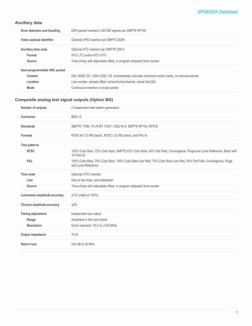
Ancillary data
Error detection and handling EDH packet inserted in SD-SDI signals per SMPTE RP165
Video payload identifier Optional VPID insertion per SMPTE 352M
Ancillary time code Optional ATC insertion per SMPTE 12M-2 Format ATC-LTC and/or ATC-VITC Source Time-of-day with adjustable offset, or program (elapsed) time counter
User-programmable ANC packet Content DID, SDID, DC, UDW (255), CS; Automatically calculate checksum and/or parity, or manual override Location Line number, sample offset, luma/chroma channel, virtual link (3G) Mode Continuous insertion or single packet
Composite analog test signal outputs (Option BG)
Number of outputs 2 independent test pattern generators
Connector BNC ×2
Standards SMPTE 170M, ITU-R BT.1700-1, EBU N14, SMPTE RP154, RP318
Formats NTSC-M (7.5 IRE black), NTSC-J (0 IRE black), and PAL-B
Test patterns NTSC 100% Color Bars, 75% Color Bars, SMPTE EG1 Color Bars, 40% Flat Field, Convergence, Pluge and Luma Reference, Black with
10 Field ID PAL 100% Color Bars, 75% Color Bars, 100% Color Bars over Red, 75% Color Bars over Red, 40% Flat Field, Convergence, Pluge
and Luma Reference
Time code Optional VITC insertion Line One or two lines, user selectable Source Time-of-day with adjustable offset, or program (elapsed) time counter
Luminance amplitude accuracy ±1% (video at 100%)
Chroma amplitude accuracy ±2%
Timing adjustment Independent per output Range Anywhere in the color frame Resolution Clock resolution 18.5 ns (1/54 MHz)
Output impedance 75 Ω
Return loss ≥30 dB to 30 MHz
SPG8000A Datasheet
12
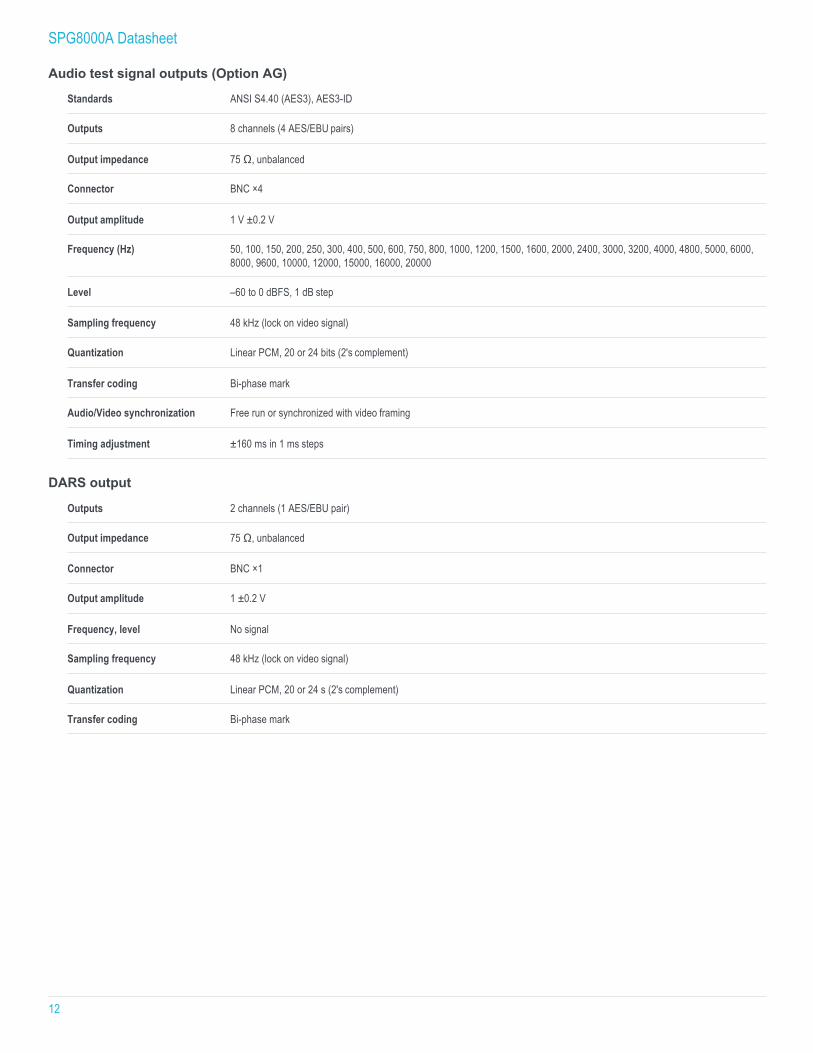
Audio test signal outputs (Option AG)
Standards ANSI S4.40 (AES3), AES3-ID
Outputs 8 channels (4 AES/EBU pairs)
Output impedance 75 Ω, unbalanced
Connector BNC ×4
Output amplitude 1 V ±0.2 V
Frequency (Hz) 50, 100, 150, 200, 250, 300, 400, 500, 600, 750, 800, 1000, 1200, 1500, 1600, 2000, 2400, 3000, 3200, 4000, 4800, 5000, 6000, 8000, 9600, 10000, 12000, 15000, 16000, 20000
Level –60 to 0 dBFS, 1 dB step
Sampling frequency 48 kHz (lock on video signal)
Quantization Linear PCM, 20 or 24 bits (2's complement)
Transfer coding Bi-phase mark
Audio/Video synchronization Free run or synchronized with video framing
Timing adjustment ±160 ms in 1 ms steps
DARS output
Outputs 2 channels (1 AES/EBU pair)
Output impedance 75 Ω, unbalanced
Connector BNC ×1
Output amplitude 1 ±0.2 V
Frequency, level No signal
Sampling frequency 48 kHz (lock on video signal)
Quantization Linear PCM, 20 or 24 s (2's complement)
Transfer coding Bi-phase mark
SPG8000A Datasheet
13
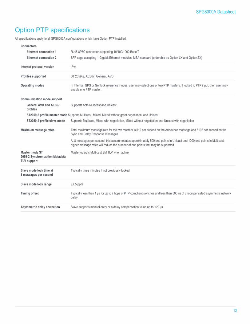
Option PTP specifications All specifications apply to all SPG8000A configurations which have Option PTP installed.
Connectors Ethernet connection 1 RJ45 8P8C connector supporting 10/100/1000 Base T Ethernet connection 2 SFP cage accepting 1 Gigabit Ethernet modules, MSA standard (orderable as Option LX and Option SX)
Internet protocol version IPv4
Profiles supported ST 2059-2, AES67, General, AVB
Operating modes In Internal, GPS or Genlock reference modes, user may select one or two PTP masters. If locked to PTP input, then user may enable one PTP master.
Communication mode support General AVB and AES67 profiles
Supports both Multicast and Unicast
ST2059-2 profile master mode Supports Multicast, Mixed, Mixed without grant negotiation, and Unicast ST2059-2 profile slave mode Supports Multicast, Mixed with negotiation, Mixed without negotiation and Unicast with negotiation
Maximum message rates Total maximum message rate for the two masters is 512 per second on the Announce message and 8192 per second on the Sync and Delay Response messages
At 8 messages per second, this accommodates approximately 500 end points in Unicast and 1000 end points in Multicast; higher message rates will reduce the number of end points that may be supported
Master mode ST 2059-2 Synchronization Metadata TLV support
Master outputs Multicast SM TLV when active
Slave mode lock time at 8 messages per second
Typically three minutes if not previously locked
Slave mode lock range ±7.5 ppm
Timing offset Typically less than 1 µs for up to 7 hops of PTP compliant switches and less than 500 ns of uncompensated asymmetric network delay
Asymmetric delay correction Slave supports manual entry or a delay compensation value up to ±20 µs
SPG8000A Datasheet
14
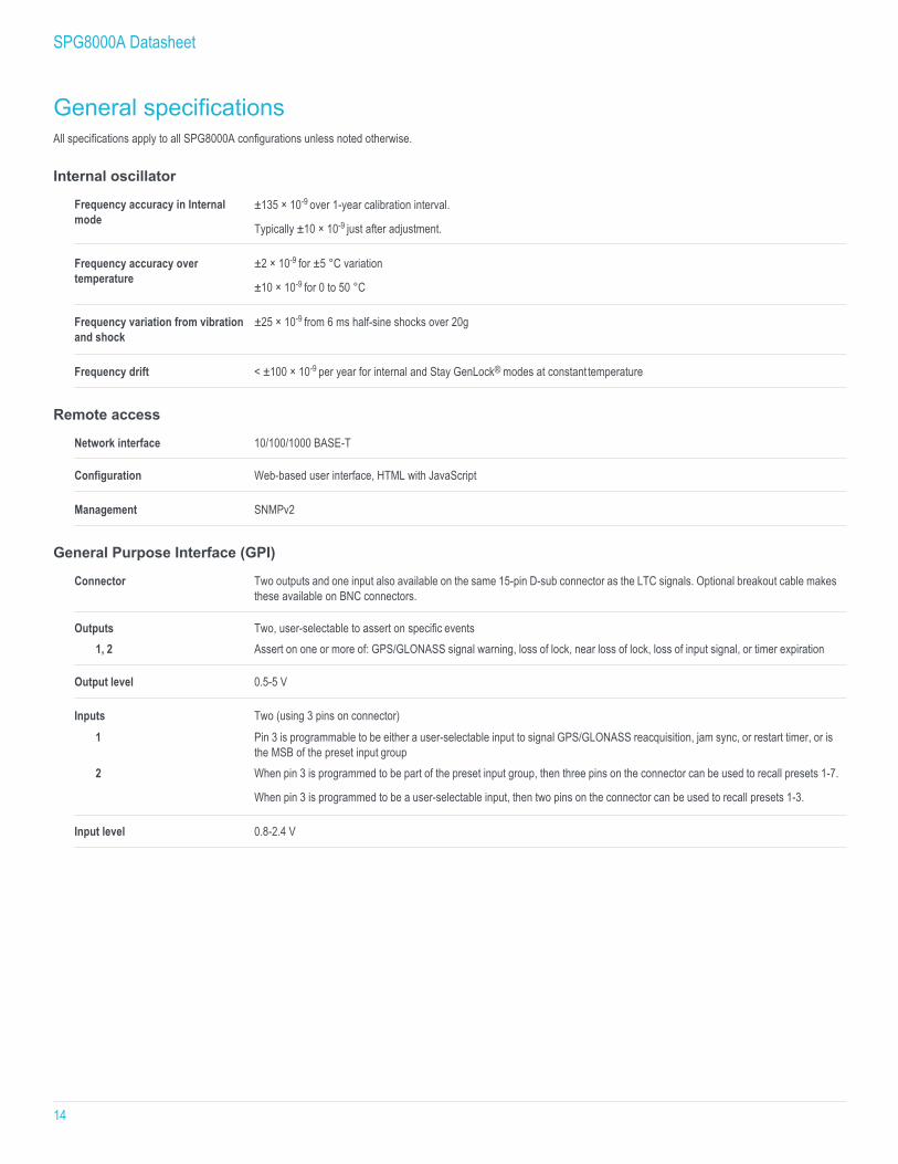
General specifications All specifications apply to all SPG8000A configurations unless noted otherwise.
Internal oscillator
Frequency accuracy in Internal mode
±135 × 10-9 over 1-year calibration interval.
Typically ±10 × 10-9 just after adjustment.
Frequency accuracy over temperature
±2 × 10⁻⁹ for ±5 °C variation
±10 × 10-9 for 0 to 50 °C
Frequency variation from vibration and shock
±25 × 10-9 from 6 ms half-sine shocks over 20g
Frequency drift < ±100 × 10-9 per year for internal and Stay GenLock® modes at constant temperature
Remote access
Network interface 10/100/1000 BASE-T
Configuration Web-based user interface, HTML with JavaScript
Management SNMPv2
General Purpose Interface (GPI)
Connector Two outputs and one input also available on the same 15-pin D-sub connector as the LTC signals. Optional breakout cable makes these available on BNC connectors.
Outputs Two, user-selectable to assert on specific events 1, 2 Assert on one or more of: GPS/GLONASS signal warning, loss of lock, near loss of lock, loss of input signal, or timer expiration
Output level 0.5-5 V
Inputs Two (using 3 pins on connector)
1 Pin 3 is programmable to be either a user-selectable input to signal GPS/GLONASS reacquisition, jam sync, or restart timer, or is the MSB of the preset input group
2 When pin 3 is programmed to be part of the preset input group, then three pins on the connector can be used to recall presets 1-7.
When pin 3 is programmed to be a user-selectable input, then two pins on the connector can be used to recall presets 1-3.
Input level 0.8-2.4 V
SPG8000A Datasheet
15
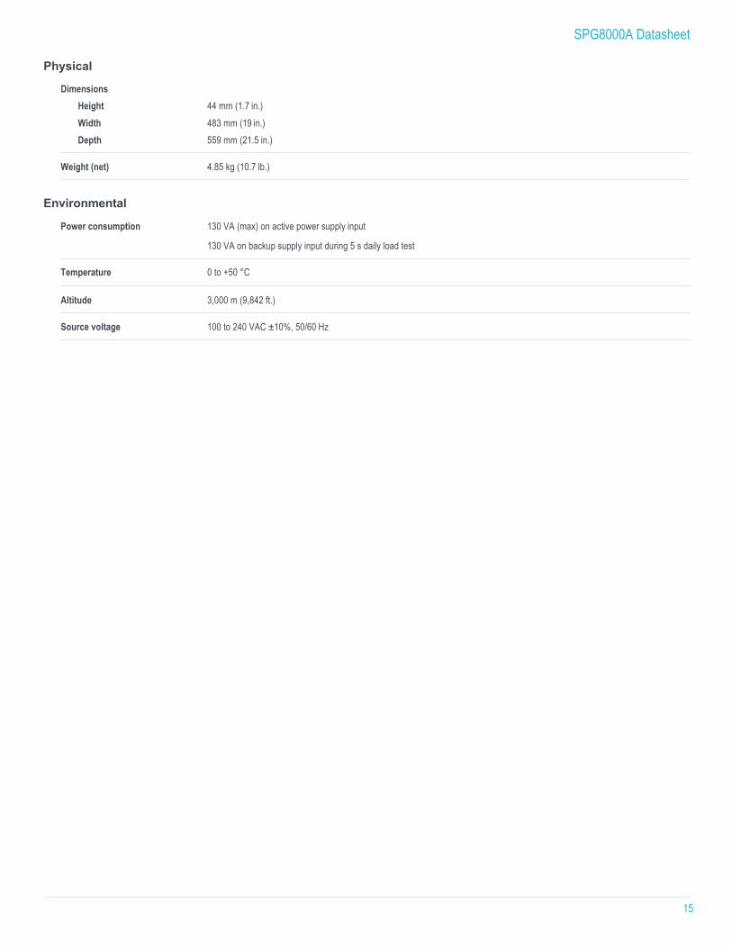
Physical
Dimensions Height 44 mm (1.7 in.) Width 483 mm (19 in.) Depth 559 mm (21.5 in.)
Weight (net) 4.85 kg (10.7 lb.)
Environmental
Power consumption 130 VA (max) on active power supply input
130 VA on backup supply input during 5 s daily load test
Temperature 0 to +50 °C
Altitude 3,000 m (9,842 ft.)
Source voltage 100 to 240 VAC ±10%, 50/60 Hz
SPG8000A Datasheet
16
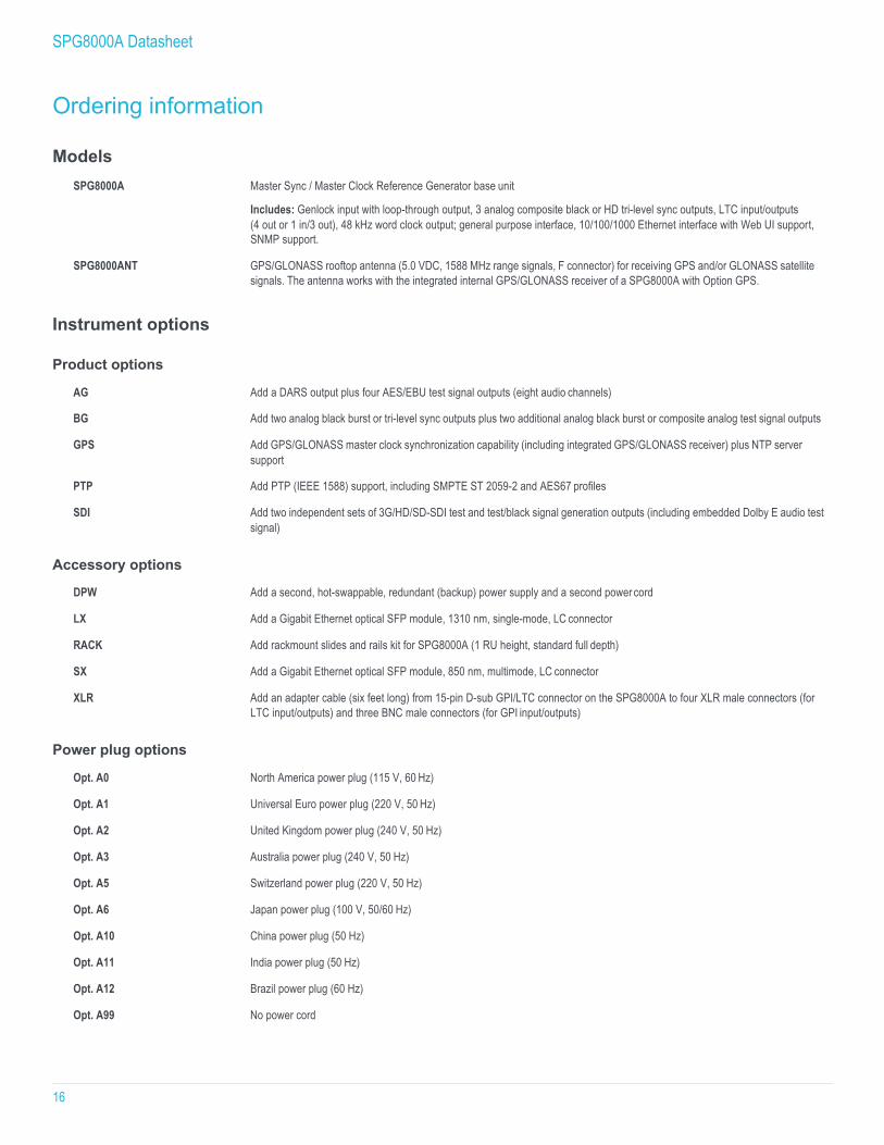
Ordering information
Models SPG8000A Master Sync / Master Clock Reference Generator base unit
Includes: Genlock input with loop-through output, 3 analog composite black or HD tri-level sync outputs, LTC input/outputs (4 out or 1 in/3 out), 48 kHz word clock output; general purpose interface, 10/100/1000 Ethernet interface with Web UI support, SNMP support.
SPG8000ANT GPS/GLONASS rooftop antenna (5.0 VDC, 1588 MHz range signals, F connector) for receiving GPS and/or GLONASS satellite signals. The antenna works with the integrated internal GPS/GLONASS receiver of a SPG8000A with Option GPS.
Instrument options
Product options
AG Add a DARS output plus four AES/EBU test signal outputs (eight audio channels)
BG Add two analog black burst or tri-level sync outputs plus two additional analog black burst or composite analog test signal outputs
GPS Add GPS/GLONASS master clock synchronization capability (including integrated GPS/GLONASS receiver) plus NTP server support
PTP Add PTP (IEEE 1588) support, including SMPTE ST 2059-2 and AES67 profiles
SDI Add two independent sets of 3G/HD/SD-SDI test and test/black signal generation outputs (including embedded Dolby E audio test signal)
Accessory options
DPW Add a second, hot-swappable, redundant (backup) power supply and a second power cord
LX Add a Gigabit Ethernet optical SFP module, 1310 nm, single-mode, LC connector
RACK Add rackmount slides and rails kit for SPG8000A (1 RU height, standard full depth)
SX Add a Gigabit Ethernet optical SFP module, 850 nm, multimode, LC connector
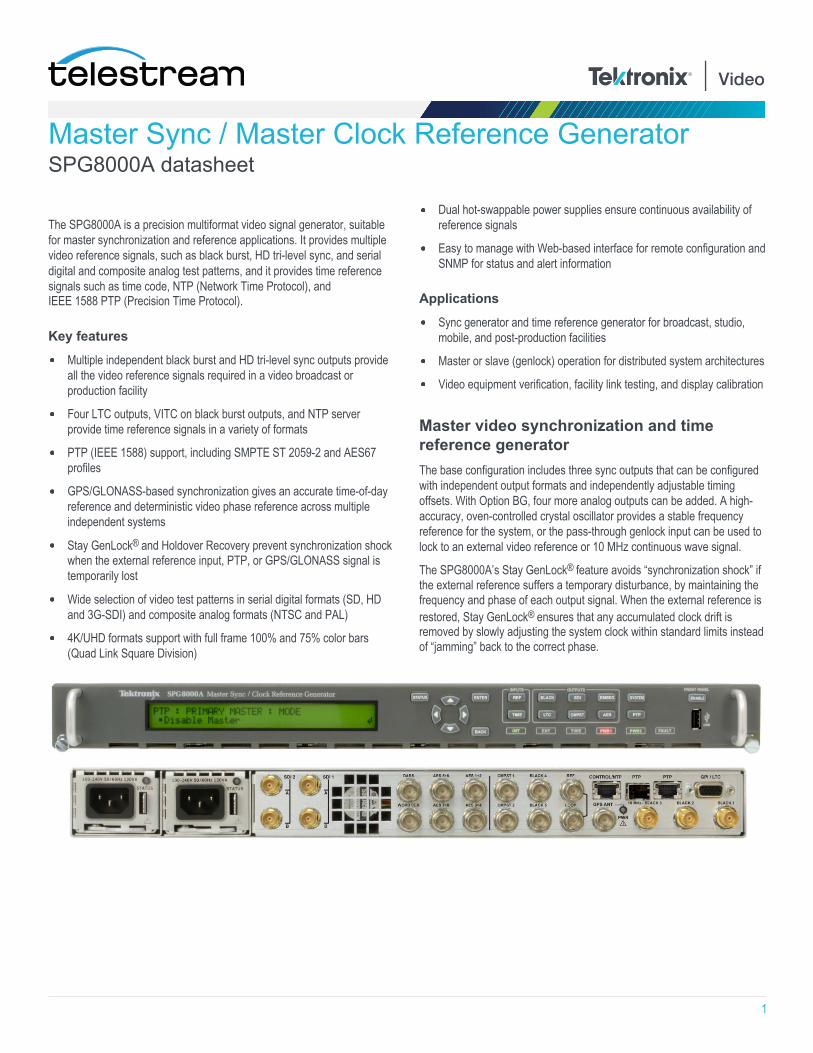
XLR Add an adapter cable (six feet long) from 15-pin D-sub GPI/LTC connector on the SPG8000A to four XLR male connectors (for LTC input/outputs) and three BNC male connectors (for GPI input/outputs)
Power plug options
Opt. A0 North America power plug (115 V, 60 Hz)
Opt. A1 Universal Euro power plug (220 V, 50 Hz)
Opt. A2 United Kingdom power plug (240 V, 50 Hz)
Opt. A3 Australia power plug (240 V, 50 Hz)
Opt. A5 Switzerland power plug (220 V, 50 Hz)
Opt. A6 Japan power plug (100 V, 50/60 Hz)
Opt. A10 China power plug (50 Hz)
Opt. A11 India power plug (50 Hz)
Opt. A12 Brazil power plug (60 Hz)
Opt. A99 No power cord
SPG8000A Datasheet
17
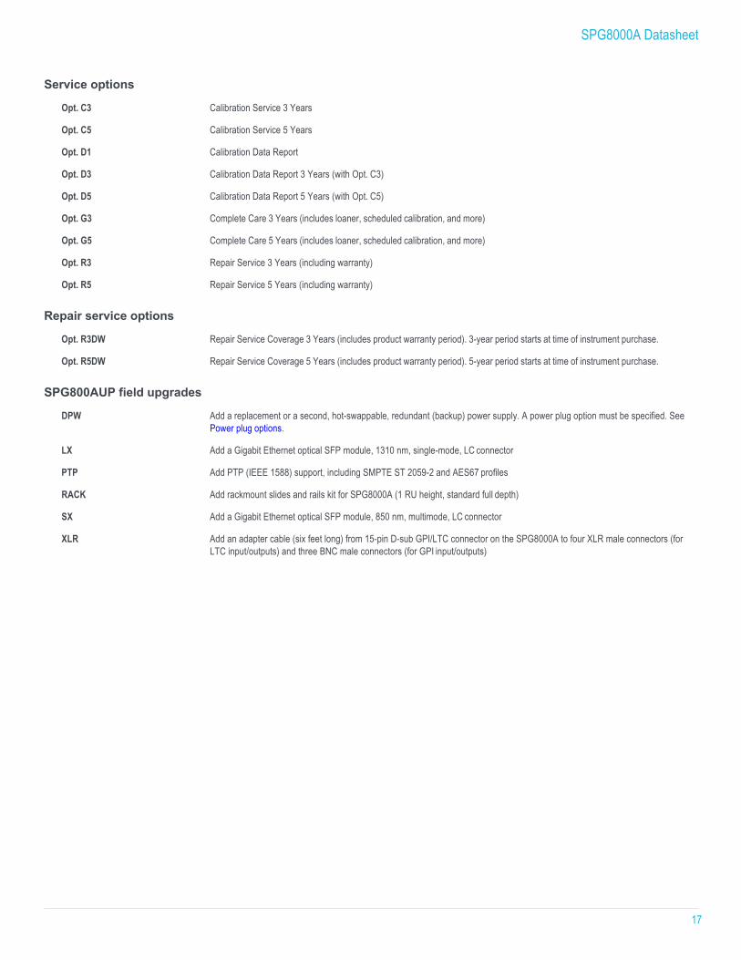
Service options
Opt. C3 Calibration Service 3 Years
Opt. C5 Calibration Service 5 Years
Opt. D1 Calibration Data Report
Opt. D3 Calibration Data Report 3 Years (with Opt. C3)
Opt. D5 Calibration Data Report 5 Years (with Opt. C5)
Opt. G3 Complete Care 3 Years (includes loaner, scheduled calibration, and more)
Opt. G5 Complete Care 5 Years (includes loaner, scheduled calibration, and more)
Opt. R3 Repair Service 3 Years (including warranty)
Opt. R5 Repair Service 5 Years (including warranty)
Repair service options
Opt. R3DW Repair Service Coverage 3 Years (includes product warranty period). 3-year period starts at time of instrument purchase.
Opt. R5DW Repair Service Coverage 5 Years (includes product warranty period). 5-year period starts at time of instrument purchase.
SPG800AUP field upgrades
DPW Add a replacement or a second, hot-swappable, redundant (backup) power supply. A power plug option must be specified. See Power plug options.
LX Add a Gigabit Ethernet optical SFP module, 1310 nm, single-mode, LC connector
PTP Add PTP (IEEE 1588) support, including SMPTE ST 2059-2 and AES67 profiles
RACK Add rackmount slides and rails kit for SPG8000A (1 RU height, standard full depth)
SX Add a Gigabit Ethernet optical SFP module, 850 nm, multimode, LC connector
XLR Add an adapter cable (six feet long) from 15-pin D-sub GPI/LTC connector on the SPG8000A to four XLR male connectors (for LTC input/outputs) and three BNC male connectors (for GPI input/outputs)
SPG8000A Datasheet
18
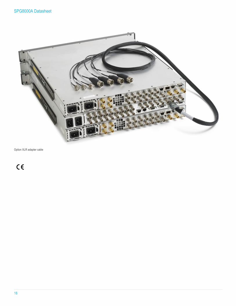
Option XLR adapter cable

SPG8000A Datasheet
19
SPG8000A Datasheet
For Further Information. Telestream maintains a comprehensive, constantly expanding collection of application notes, technical briefs and other resources to help engineers working on the cutting edge of technology. Please visit www.telestream.net/video for sales and support contacts.
Copyright © 2019 Telestream, LLC and its Affiliates. All rights reserved. Telestream products are covered by U.S. and foreign patents, issued and pending. Information in this publication supersedes that in all previously published material. Specification and price change privileges reserved. TELESTREAM is a registered trademark of Telestream, LLC. All other trade names referenced are the service marks, trademarks, or registered trademarks of their respective companies.
05 Jul 2018 20W-602611