Embed Size (px)
Citation preview

Treball Final de Màster
Study of Combustion Using a Computational Fluid Dynamics Software (ANSYS)
Estudio de la Combustión Usando Software de Dinámica de Fluidos
Computacional (ANSYS)
Jose Manuel Iglesias Fernández
February, 2015
Tutor/s
Dr. Jordi Bonet Ruiz Departament Enginyeria Química
Dr. Joan Llorens Llacuna Departament Enginyería Química
Màster en
Enginyeria
Química

Study of Combustion by using CFD(ANSYS)

Study of Combustion by using CFD(ANSYS)
Aquesta obra esta subjecta a la llicència de
Reconeixement-NoComercial-
SenseObraDerivada
http://creativecommons.org/licenses/by-nc-
nd/3.0/es/

Study of Combustion by using CFD(ANSYS)
Study of Combustion by using CFD(ANSYS)
No se equivoca el hombre que prueba distintos caminos para alcanzar sus metas,
se equivoca aquél que por temor a equivocarse no actúa.
Anónimo
En primer lugar, agradecer toda la dedicación y trabajo de mis tutores, y
profesorado que han estado implicados en la realización de este trabajo. También
agradecer a todas aquellas personas, familia, amigos, compañeros, maestros, etc.
Que de alguna manera u otra han estado presentes, animándome para seguir
siempre adelante y crecer tanto como persona como como profesional.

Study of Combustion by using CFD(ANSYS)
Study of Combustion by using CFD(ANSYS)
Contents
1. SUMMARY ................................................................................................... 1
2. INTRODUCTION .......................................................................................... 3
3. OBJECTIVES ................................................................................................ 5
4. REVIEW OF THE STATE OF THE ART .................................................... 7
4.1. Numerical simulation of combustion ...................................................... 7
4.2. Water addition in combustion systems ................................................... 9
5. COMPUTATIONAL FLUID DYNAMICS: ANSYS-FLUENT ................ 11
5.1. Performing a simulation in ANSYS: FLUENT .................................... 12
5.1.1. Geometry design ............................................................................... 13
5.1.2. Mesh generation ............................................................................... 13
5.1.3. Simulation Setup .............................................................................. 16
6. SENSITIVITY ANALYSIS ......................................................................... 21
7. RESULTS..................................................................................................... 23
7.1. Temperature profiles ............................................................................. 25
7.2. NOx ppm profiles ................................................................................. 31
7.3. Thermal NOx rate profiles .................................................................... 37
7.4. Promp NOx rate profiles ....................................................................... 43
7.5. Radical [O] profiles .............................................................................. 49
7.6. Radical [OH] profiles ............................................................................ 55
8. CONCLUSIONS .......................................................................................... 61
9. FUTURE WORK ......................................................................................... 62
REFERENCES ..................................................................................................... 63

Study of Combustion by using CFD(ANSYS)

Study of Combustion by using CFD(ANSYS) 1
1. SUMMARY
This work is a study of the effect of water addition to a combustion chamber. Starting
from a review of the art and literature to understand the NOx formation phenomena and
then, using the commercial computational fluid dynamics software ANSYS FLUENT to
perform a sensitivity analysis of this water addition.
More specifically, first is a description of what can be found when searching for
computational fluid dynamics and water injection engines. Secondly, there is shown the
structure and the main characteristics of a simulation performed in ANSYS FLUENT.
Finally, there’s posed a sensitivity analysis in order to see the effect of the water addition
to a combustor, and the influence of the contact mode used to implement this addition.

Study of Combustion by using CFD(ANSYS) 2
Study of Combustion by using CFD(ANSYS) 3
2. INTRODUCTION
Combustion is present in many different aspects of our lives, from lighters or water
heating in home-scale heaters to airplane reactors. Since the phenomena of combustion
is a very important part of our daily lives and it’s the main source of heat used in the
industry it results in a very attractive field of study for many reasons. The next paragraphs
can illustrate some of this reasons.
Firstly, as a main source of energy, there’s the necessity to maximize the efficiency
of the combustion systems and obtain the maximum profit from the resources. Secondly,
it is not just the concern about the efficiency what boost the studies about combustion.
These processes must be environment-friendly and one of the most limiting aspect for
the optimization of the combustion systems is the pollution associated with it. All the
pollution associated with these systems (NOx, SOx, VOC’s,CO,CO2) and it’s direct
relation with global warming is a strong reason to spend resources in technology to
improve the combustion systems. For instance, in these days the newsletters has been
filled of news about the production of oxidized compounds of nitrogen (NOx) in diesel
engines and possible measures to solve the problem [8].
On the other hand, computational resources are increasing in an astonishing rate,
which allows us to perform simulations in such detail and velocity that was unbelievable
a few years ago. Also, this allows to reduce the time spent in an investigation as the use
of computation can be useful for a first approach and save time and money in expensive
experiments.
This final project is intended to use the advantages resulting from the availability of
these computational resources and apply it to the study of NOx emissions in combustion
systems. More exactly, the effect of water addition to combustion systems.

Study of Combustion by using CFD(ANSYS) 4
Study of Combustion by using CFD(ANSYS) 5
3. OBJECTIVES
The objective of this work is the study of NOx formation in systems where vapour-
water is present in the reaction system by using a commercial Computational Fluid
Dynamics software (ANSYS: Fluent). In order to carry out this study, the work has been
divided in some specific, measurable, achievable, realistic and time-based objectives.
Those objectives are:
See what has been done in the field of the study of combustion by using CFD
and systems where vapour-water is used to reduce the pollution due to NOx
(a review of the state of the art).
Learn how to use the selected commercial simulator and its capabilities.
Select an appropriated case study.
Provide a virtual laboratory to study the combustion.
Perform a sensitivity analysis to see the effect of water addition into the
combustion system in the NOx emissions.

Study of Combustion by using CFD(ANSYS) 6
Study of Combustion by using CFD(ANSYS) 7
4. REVIEW OF THE STATE OF THE ART
4.1. NUMERICAL SIMULATION OF COMBUSTION
The study of NOx production by using CFD is not widely used. When searching
for papers related to it, just a few but interesting results can be found. Specifically,
Byeonghun et al (2015) provides a recent clear example about the concern about this
subject. In this paper, the authors carry out a study of the NOx emission characteristics
when burning a methane-air mixture in a combustor. The study includes both
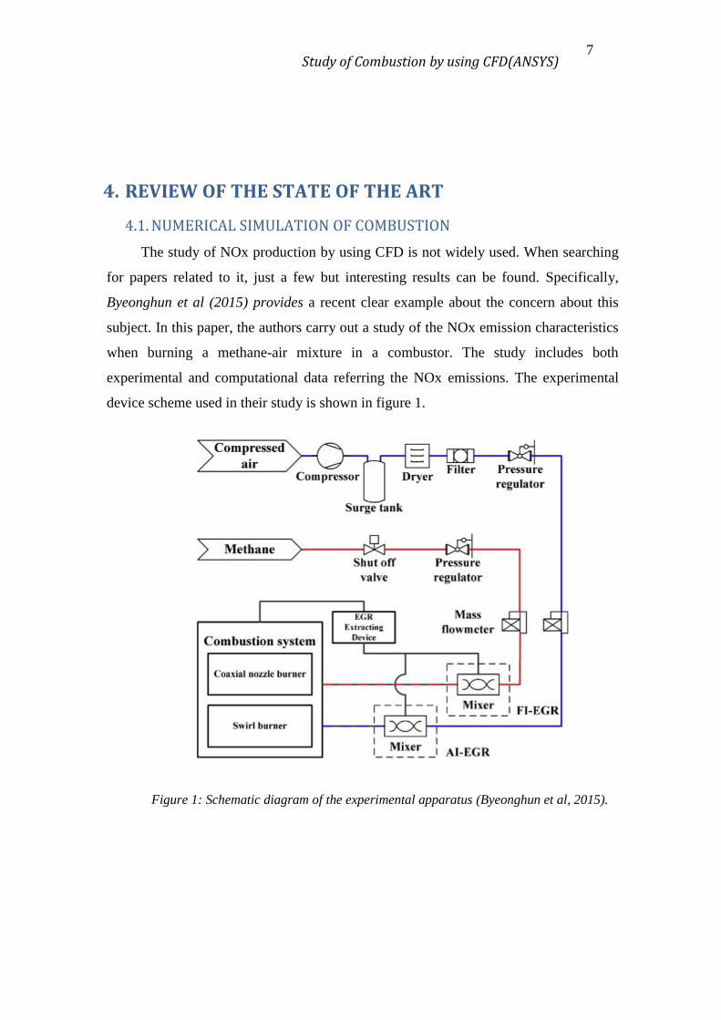
experimental and computational data referring the NOx emissions. The experimental
device scheme used in their study is shown in figure 1.
Figure 1: Schematic diagram of the experimental apparatus (Byeonghun et al, 2015).
Study of Combustion by using CFD(ANSYS) 8
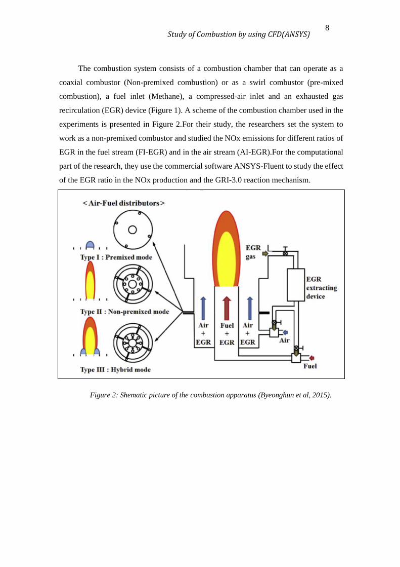
The combustion system consists of a combustion chamber that can operate as a
coaxial combustor (Non-premixed combustion) or as a swirl combustor (pre-mixed
combustion), a fuel inlet (Methane), a compressed-air inlet and an exhausted gas
recirculation (EGR) device (Figure 1). A scheme of the combustion chamber used in the
experiments is presented in Figure 2.For their study, the researchers set the system to
work as a non-premixed combustor and studied the NOx emissions for different ratios of
EGR in the fuel stream (FI-EGR) and in the air stream (AI-EGR).For the computational
part of the research, they use the commercial software ANSYS-Fluent to study the effect
of the EGR ratio in the NOx production and the GRI-3.0 reaction mechanism.
Figure 2: Shematic picture of the combustion apparatus (Byeonghun et al, 2015).
Study of Combustion by using CFD(ANSYS) 9
4.2. WATER ADDITION IN COMBUSTION SYSTEMS
Several experiments has been carried out in the last years, showing the positive
effects in terms of pollutants reductions when water-injection engines are employed (e.g.
(2)). However, it is not only a laboratory field of study. The water-injection engines has
been commercially used in aircraft engines, marine engines and automation engines.
Those systems can help to overcome the challenge arisen from the increasingly restrictive
legislation about the NOx emissions [10].
The addition of water have some effects when talking about the thermodynamic
and the chemistry of the combustion system. An example of the effects in the
thermodynamics is that the initial injection of water, cools the fuel-air mixture
significantly, resulting in an increase of the compression ratio that can be acquired in the
system. Also, the addition of water minimizes the temperature peaks during the
combustion process, hence a reduction of NOx formation will happen, as it tend to appear
at high temperatures.
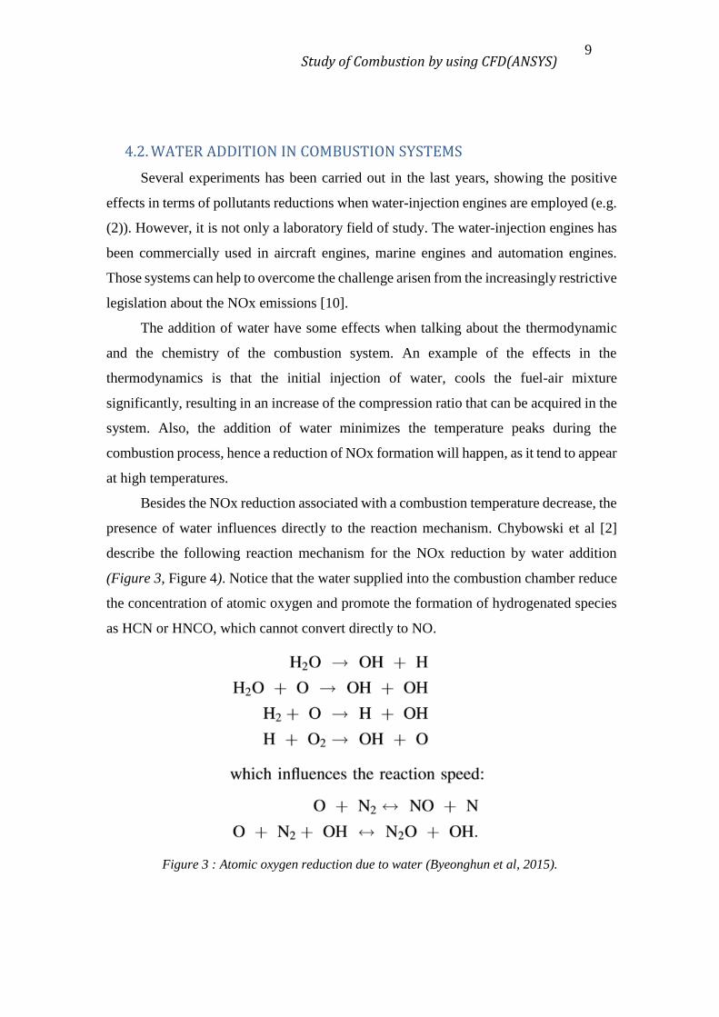
Besides the NOx reduction associated with a combustion temperature decrease, the
presence of water influences directly to the reaction mechanism. Chybowski et al [2]
describe the following reaction mechanism for the NOx reduction by water addition
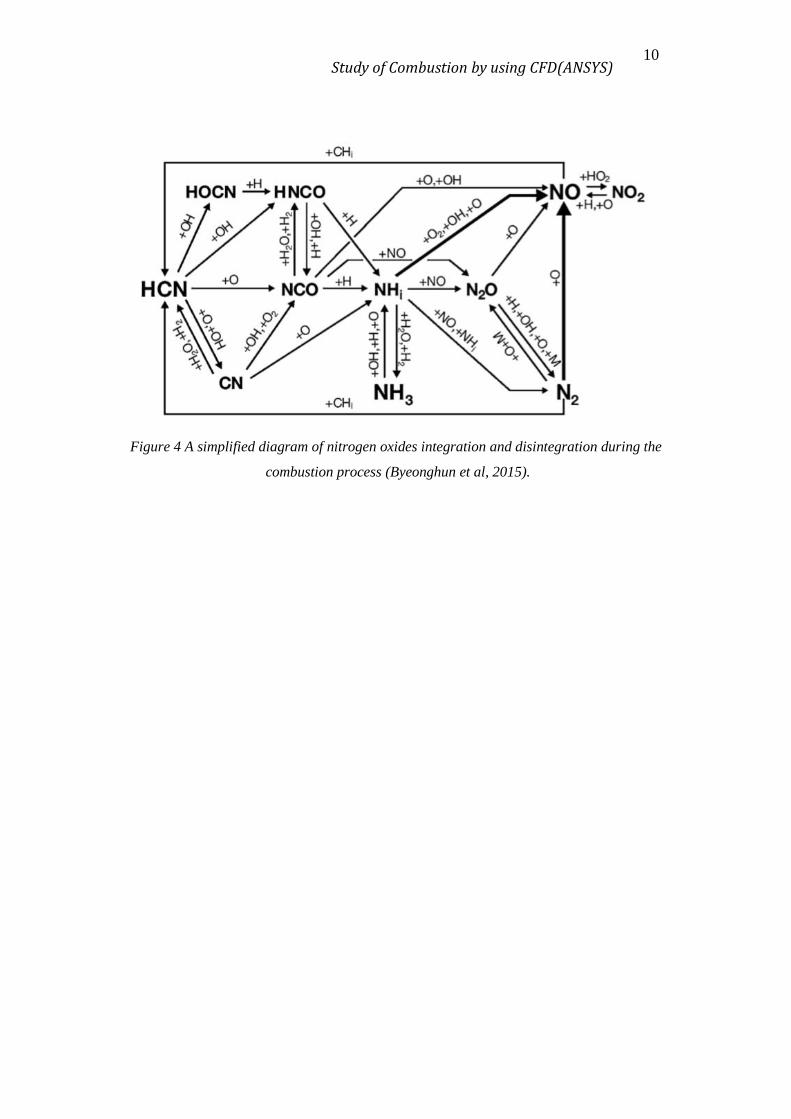
(Figure 3, Figure 4). Notice that the water supplied into the combustion chamber reduce
the concentration of atomic oxygen and promote the formation of hydrogenated species
as HCN or HNCO, which cannot convert directly to NO.
Figure 3 : Atomic oxygen reduction due to water (Byeonghun et al, 2015).
Study of Combustion by using CFD(ANSYS) 10
Figure 4 A simplified diagram of nitrogen oxides integration and disintegration during the
combustion process (Byeonghun et al, 2015).
Study of Combustion by using CFD(ANSYS) 11
5. COMPUTATIONAL FLUID DYNAMICS: ANSYS-FLUENT
Computational Fluid Dynamics (CFD) simulation provides a virtual laboratory to
perform experiments in the early stages of design without building the physical
apparatus. Virtual environments decreases the unit design costs as the number of
unsatisfactory experimental devices that ends to scrap decrease drastically. Otherwise,
the cost of experimental device and its operation until obtain satisfactory results can
become very huge. Simulations can be done by CFD modelling using commercial or own
software with the same base: “CFD simulations use mathematical models which
represents the different phenomena occurring in the system.”
The accuracy of a CFD simulation to the real solution depends on the appropriated
selection of the models. Hence, the use of a commercial and widely use commercial
software, which its models are widely accepted and validated against experimental data,
is recommended. In this work, the CFD software used was ANSYS.

Study of Combustion by using CFD(ANSYS) 12
5.1. PERFORMING A SIMULATION IN ANSYS: FLUENT
ANSYS is a software suit that spans the entire range of physics, providing access
to lots of fields of engineering simulation that a design process require. In particular, the
module FLUENT is appropriate for this work. FLUENT’s models are focused on fluids
flow and chemical reactions, including a very good model to run a first-approach
simulations of combustion systems.
In the next sections, it’s explained the main characteristics of how to perform a
simulation using ANSYS: Fluent. Starting, but not focusing, on the geometry and mesh
creation, and continuing on how to set up the models and run the calculations. the
ANSYS FLUENT Tutorial Guide (ANSYS, 2015), to perform this kind of simulations it
is required to attain the “Chapter 16: Modelling Species Transport and Gaseous
Combustion”, example problem number 16. In this problem, it’s studied the combustion
of methane in air, in turbulent flow, and using a simple reaction mechanism. Once
achieved the basic skills from the tutorial, we are ready to simulate the effect of water
addition to the NOx formation.
To perform a simulation in ANSYS FLUENT, the next steps are followed:
Design the geometry of the system.
Discretise the geometry by generating an appropriated mesh.
Set up the models to represent the reality adequately.
Configure the calculation’s parameters to run the simulation and obtain results.
Results retrieval and visualization.

Study of Combustion by using CFD(ANSYS) 13
5.1.1. Geometry design
Figure 5 provides the configuration and dimensions of the combustion chamber
used in the simulations as well as the fuel and air rates passing through the system.
Figure 5 : Calculation domain (ANSYS, 2015)
This is a representation of a non-premixed combustion chamber but, due to the
high level of symmetry present in the system, the calculation domain can be reduced to
a 2D problem assuming no variations in the radial coordinate. If done, the computational
time required for the calculations decrease drastically.
5.1.2. Mesh generation
Concerning the microscopic balances, notice that all the governing equations are
differential equations with a continuous solution along the space. The system
discretisation is the way to assign the mathematical model to a finite element of the
system, transform those differential equations in algebraic equations, and then, solve the
system. That is called finite element method.
The approximation of differential equations to finite increments introduce an error
that is bigger as bigger is the size of the finite element but, the error associated to a
determined point is also dependant of the derivatives intensity. Hence, if there is a zone
Study of Combustion by using CFD(ANSYS) 14
where an intense phenomena is occurring (i.e. intense chemical reactions or high energy
turbulences), the size of the elements must be reduced to improve solution accuracy.
Undiscrimate use of an uniform tiny mesh size everywhere leads to unachievable
computing power requirements.
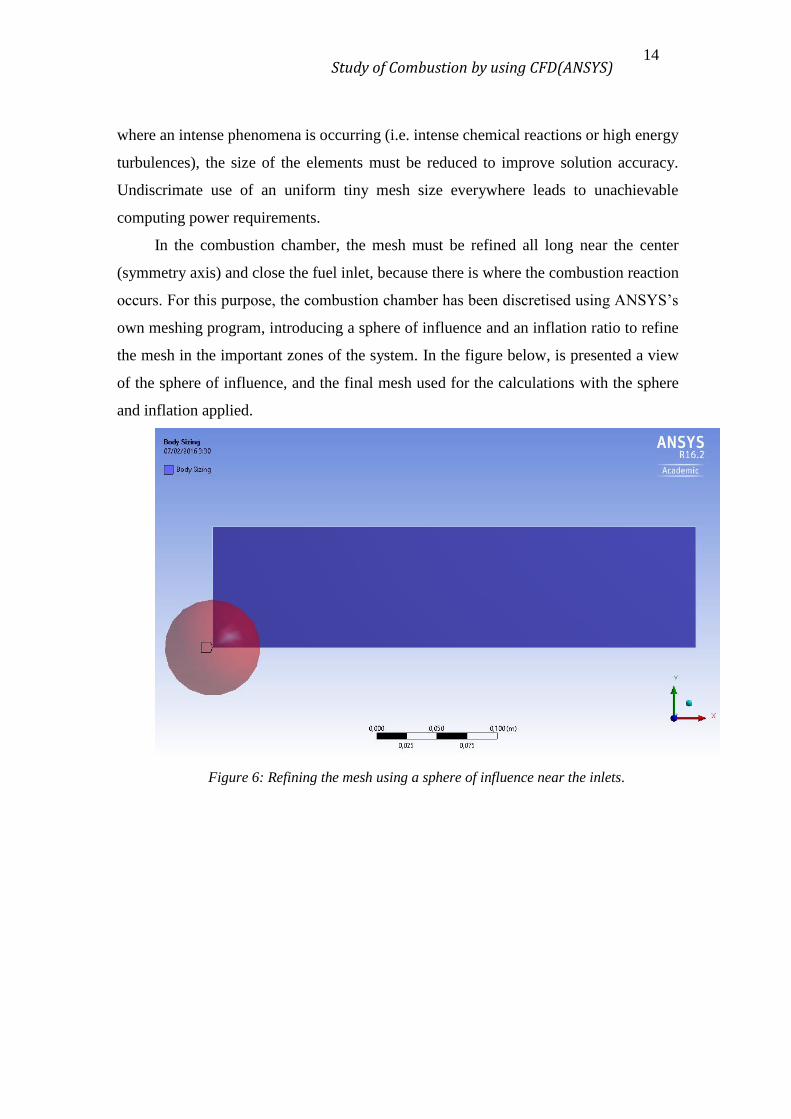
In the combustion chamber, the mesh must be refined all long near the center
(symmetry axis) and close the fuel inlet, because there is where the combustion reaction
occurs. For this purpose, the combustion chamber has been discretised using ANSYS’s
own meshing program, introducing a sphere of influence and an inflation ratio to refine
the mesh in the important zones of the system. In the figure below, is presented a view
of the sphere of influence, and the final mesh used for the calculations with the sphere
and inflation applied.
Figure 6: Refining the mesh using a sphere of influence near the inlets.

Study of Combustion by using CFD(ANSYS) 15
Figure 7: Final mesh with the sphere of influence in the fuel inlet and the inflation factor
in the symmetry axis.
Figure 8: Zoom-in at the zone of high discretisation.
Study of Combustion by using CFD(ANSYS) 16
5.1.3. Simulation Setup
As commented before, this is the step where all the models are assigned to the
design modelled in the previous parts. ANSYS has some valid applications available that
could solve the problem posed in this work. The software ANSYS FLUENT has been
selected because it incorporates a good package for simulate the combustion phenomena.
Inside FLUENT the setup consists in the following parts, necessary to perform the
calculations.
Models definition: it is the part where is defined which models are selected to as
describe the different phenomena present in the system.
Boundary Conditions: Set the different inlets, outlets and limits of the system.
Calculation Parameters: Set the solution methods and controls.
Models definition
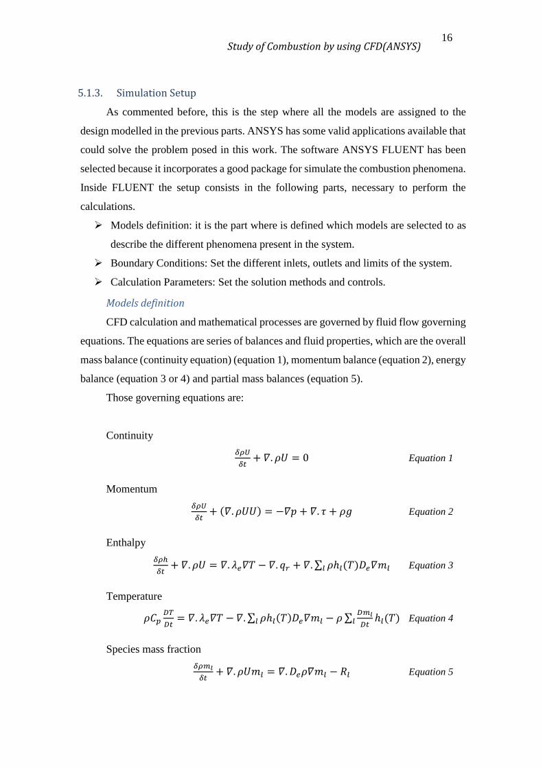
CFD calculation and mathematical processes are governed by fluid flow governing
equations. The equations are series of balances and fluid properties, which are the overall
mass balance (continuity equation) (equation 1), momentum balance (equation 2), energy
balance (equation 3 or 4) and partial mass balances (equation 5).
Those governing equations are:
Continuity
𝛿𝜌𝑈
𝛿𝑡+ 𝛻. 𝜌𝑈 = 0 Equation 1
Momentum
𝛿𝜌𝑈
𝛿𝑡+ (𝛻. 𝜌𝑈𝑈) = −𝛻𝑝 + 𝛻. 𝜏 + 𝜌𝑔 Equation 2
Enthalpy
𝛿𝜌ℎ
𝛿𝑡+ 𝛻. 𝜌𝑈 = 𝛻. 𝜆𝑒𝛻𝑇 − 𝛻. 𝑞𝑟 + 𝛻. ∑ 𝜌ℎ𝑙(𝑇)𝐷𝑒𝛻𝑚𝑙𝑙 Equation 3
Temperature
𝜌𝐶𝑝𝐷𝑇
𝐷𝑡= 𝛻. 𝜆𝑒𝛻𝑇 − 𝛻. ∑ 𝜌ℎ𝑙(𝑇)𝐷𝑒𝛻𝑚𝑙 − 𝜌 ∑
𝐷𝑚𝑙
𝐷𝑡ℎ𝑙(𝑇)𝑙𝑙 Equation 4
Species mass fraction
𝛿𝜌𝑚𝑙
𝛿𝑡+ 𝛻. 𝜌𝑈𝑚𝑙 = 𝛻. 𝐷𝑒𝜌𝛻𝑚𝑙 − 𝑅𝑙 Equation 5

Study of Combustion by using CFD(ANSYS) 17
FLUENT discretise those governing equations for every point of the system. To
obtain de different properties that are needed to solve those discretised equations (i.e.
viscous behaviour, radiation energy transfer, or chemical reactions) FLUENT resorts to
different models in order to estimate these parameters. The use and selection of these
models depends on the nature of the problem to be solved. For this work all this equations
need to be solve and the following models must be activated to estimate the turbulences
(viscous model), the radiation term, and the species distribution and kinetics.
Viscous model
The viscous model must be activated because there is a fluid flowing through the
system. One of the most accepted and used models to estimate the turbulent-flow
behaviour of the combustion systems is the k-epsilon model (6).This model is practical
for many flows and its convergence is usually easy. The model is composed by two
equations including the turbulent kinetic energy (𝑘) (equation 6) and the turbulent
dissipation rate (𝜖) (equation7).
𝛿(𝜌𝑘)
𝛿𝑡+
𝛿(𝜌𝑘𝑢𝑖)
𝛿𝑥𝑖=
𝛿
𝛿𝑥𝑗[(𝜇 +
𝜇𝑡
𝜎𝑘)
𝛿𝑘
𝛿𝑥𝑗] + 𝑃𝑘+𝑃𝑏 + 𝜌𝜖 − 𝑌𝑀 + 𝑆𝑘Equation 6
𝛿(𝜌∈)
𝛿𝑡+
𝛿(𝜌∈𝑢𝑖)
𝛿𝑥𝑖=
𝛿
𝛿𝑥𝑗[(𝜇 +
𝜇𝑡
𝜎∈)
𝛿∈
𝛿𝑥𝑗] + 𝐶1∈
∈
𝑘(𝑃𝑘 + 𝐶3∈𝑃𝑏) − 𝜌𝐶2∈
𝜖2
𝑘+ 𝑆∈ Equation 7
Radiation model
The radiation model must be activated because of the high temperature achieved
in the system. The P-1 radiation model is the simplest case of the more general P-N
model, which is based on the expansion of the radiation intensity into an orthogonal
series of spherical harmonics. The radiation flux term (−∇ · 𝑞𝑟.) in the energy balance
equation (equation 3) is provided by the equation 8. For more information see section
5.3.3: P-1 Radiation Model Theory (7).
−𝛻 · 𝑞𝑟 = 𝑎𝐺 − 4𝑎𝑛2𝜎𝑇4 Equation 8
Where 𝑎 is the absorption coefficient, 𝑛 is the refractive index of the medium, 𝜎
is the Stefan-Boltzmann constant and 𝐺 is the incident radiation.
Study of Combustion by using CFD(ANSYS) 18
Species transport: non-premixed model
As commented before, the non-premixed combustion occurs when the fuel and the
oxidizer enter the reaction zone in distinct streams.Under certain assumptions, the
thermochemistry can be reduced to a single parameter: the mixture fraction. The mixture
fraction, denoted by 𝑓, is the mass fraction that originated from the fuel stream. In other
words, it is the local mass fraction of burnt and unburnt fuel stream elements (C, H, etc.)
in all the species (CO2, H2O, O2, etc.). Hence, the mixture fraction is a conserved scalar
quantity, and therefore its governing transport equation does not have a source term.
Combustion is simplified to a mixing problem. Hence, all the species’ parameters
required for the transport equations are defined in terms of the mixture fraction and the
difficulties associated with closing non-linear mean reaction rates are avoided for non-
premixed combustion (7).
The basis of the non-premixed modelling approach is that under a certain set of
simplifying assumptions, the instantaneous thermochemical state of the fluid is related
to a conserved scalar quantity known as the mixture fraction, 𝑓. The mixture fraction
can be written in terms of the atomic mass fraction (equation 9).
𝑓 =𝑍𝑖−𝑍𝑖,𝑂𝑋
𝑍𝑖,𝑓𝑢𝑒𝑙−𝑍𝑖,𝑂𝑋 Equation 9
Where 𝑍𝑖 is the elemental mass fraction for element, . The subscript OX denotes
the value at the oxidizer stream inlet and the subscript fuel denotes the value at the fuel
𝑍𝑖−𝑍𝑖,𝑂𝑋𝑍𝑖,𝑓𝑢𝑒𝑙−𝑍𝑖,𝑂𝑋 Equation 9 is identical for all elements, and the mixture
fraction definition is unique. The mixture fraction is thus the elemental mass fraction that
originated from the fuel stream.
Study of Combustion by using CFD(ANSYS) 19
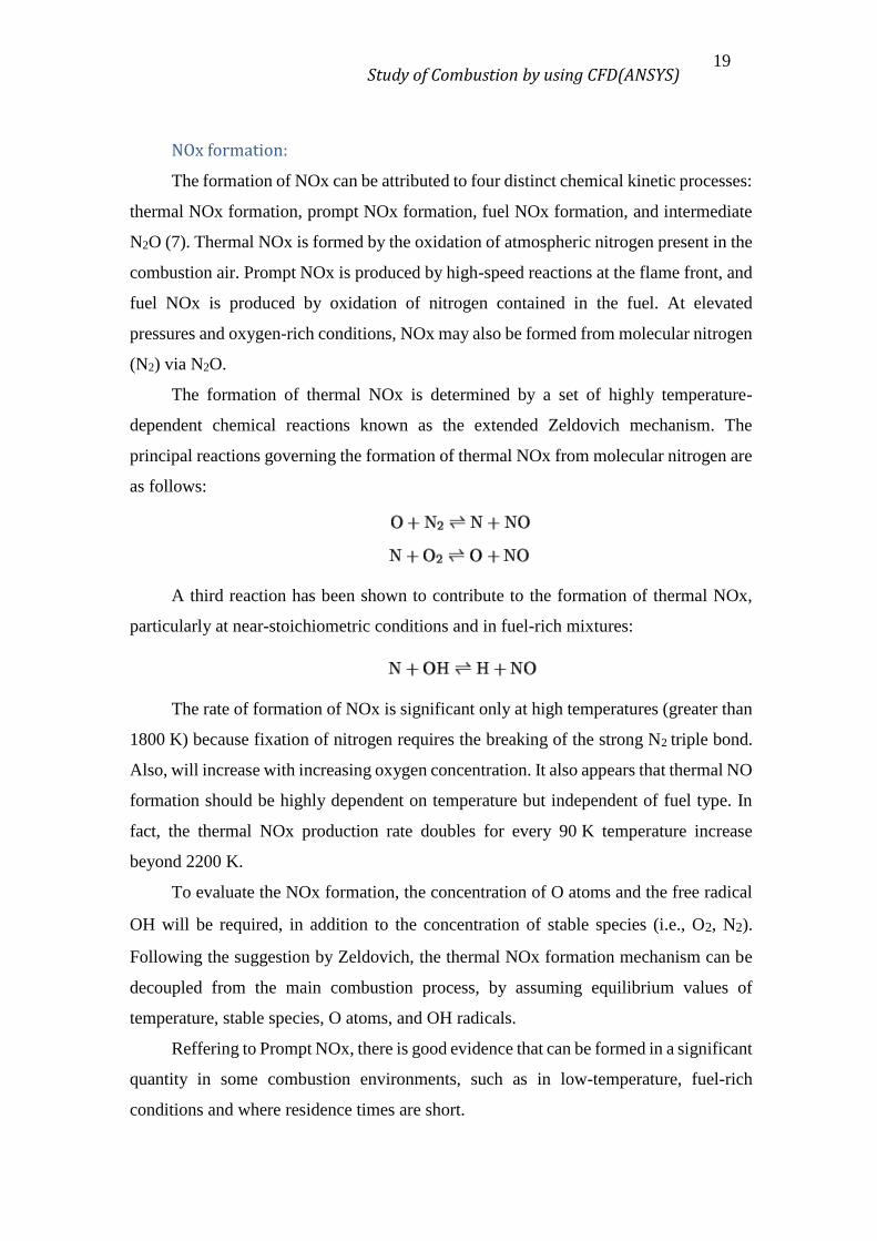
NOx formation:
The formation of NOx can be attributed to four distinct chemical kinetic processes:
thermal NOx formation, prompt NOx formation, fuel NOx formation, and intermediate
N2O (7). Thermal NOx is formed by the oxidation of atmospheric nitrogen present in the
combustion air. Prompt NOx is produced by high-speed reactions at the flame front, and
fuel NOx is produced by oxidation of nitrogen contained in the fuel. At elevated
pressures and oxygen-rich conditions, NOx may also be formed from molecular nitrogen
(N2) via N2O.
The formation of thermal NOx is determined by a set of highly temperature-
dependent chemical reactions known as the extended Zeldovich mechanism. The
principal reactions governing the formation of thermal NOx from molecular nitrogen are
as follows:
A third reaction has been shown to contribute to the formation of thermal NOx,
particularly at near-stoichiometric conditions and in fuel-rich mixtures:
The rate of formation of NOx is significant only at high temperatures (greater than
1800 K) because fixation of nitrogen requires the breaking of the strong N2 triple bond.
Also, will increase with increasing oxygen concentration. It also appears that thermal NO
formation should be highly dependent on temperature but independent of fuel type. In
fact, the thermal NOx production rate doubles for every 90 K temperature increase
beyond 2200 K.
To evaluate the NOx formation, the concentration of O atoms and the free radical
OH will be required, in addition to the concentration of stable species (i.e., O2, N2).
Following the suggestion by Zeldovich, the thermal NOx formation mechanism can be
decoupled from the main combustion process, by assuming equilibrium values of
temperature, stable species, O atoms, and OH radicals.
Reffering to Prompt NOx, there is good evidence that can be formed in a significant
quantity in some combustion environments, such as in low-temperature, fuel-rich
conditions and where residence times are short.
Study of Combustion by using CFD(ANSYS) 20
At present the prompt NOx contribution to total NOx from stationary combustors
is small. However, as NOx emissions are reduced to very low levels by employing new
strategies (burner design or furnace geometry modification), the relative importance of
the prompt NOx can be expected to increase.
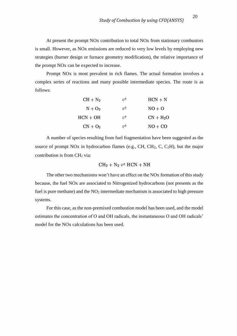
Prompt NOx is most prevalent in rich flames. The actual formation involves a
complex series of reactions and many possible intermediate species. The route is as
follows:
A number of species resulting from fuel fragmentation have been suggested as the
source of prompt NOx in hydrocarbon flames (e.g., CH, CH2, C, C2H), but the major
contribution is from CH2 via:
The other two mechanisms won’t have an effect on the NOx formation of this study
because, the fuel NOx are associated to Nitrogenized hydrocarbons (not presents as the
fuel is pure methane) and the NO2 intermediate mechanism is associated to high pressure
systems.
For this case, as the non-premixed combustion model has been used, and the model
estimates the concentration of O and OH radicals, the instantaneous O and OH radicals’
model for the NOx calculations has been used.
Study of Combustion by using CFD(ANSYS) 21
6. SENSITIVITY ANALYSIS
Once some practice with ANSYS FLUENT has been acquired, one can use it to
perform parametric analysis of a system, where almost all the variables stay static but a
few change. That allows to see and the effect of this change. The first step is to set a base
case. The next table show the flow rates of this case and the excess percentage referring
to the stoichiometric flow rate. The results obtained from this simulation will be named
as “0% water”, (it is the dry case run).
Table 1 0% simulation flow rates.
Fuel Rate [kg/s]
Air Rate [kg/s]
Excess Air Percentage [%]
4.095·10-3 9.020·10-2 25
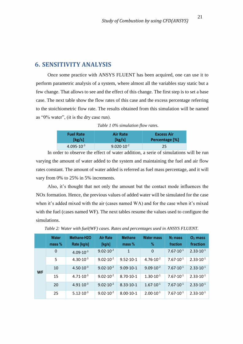
In order to observe the effect of water addition, a serie of simulations will be run
varying the amount of water added to the system and maintaining the fuel and air flow
rates constant. The amount of water added is referred as fuel mass percentage, and it will
vary from 0% to 25% in 5% increments.
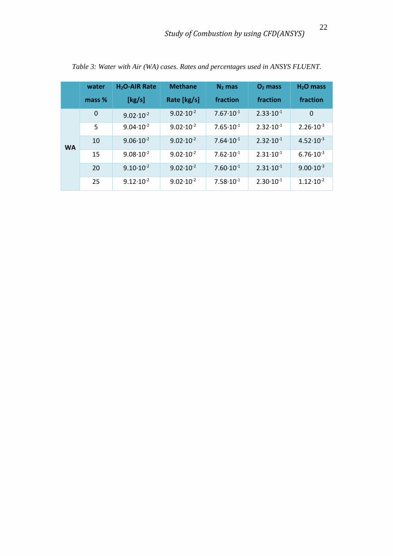
Also, it’s thought that not only the amount but the contact mode influences the
NOx formation. Hence, the previous values of added water will be simulated for the case
when it’s added mixed with the air (cases named WA) and for the case when it’s mixed
with the fuel (cases named WF). The next tables resume the values used to configure the
simulations.
Table 2: Water with fuel(WF) cases. Rates and percentages used in ANSYS FLUENT.
Water
mass %
Methane-H2O
Rate [kg/s]
Air Rate
[kg/s]
Methane
mass %
Water mass
%
N2 mass
fraction
O2 mass
fraction
WF
0 4.09·10-3 9.02·10-2 1 0 7.67·10-1 2.33·10-1
5 4.30·10-3 9.02·10-2 9.52·10-1 4.76·10-2 7.67·10-1 2.33·10-1
10 4.50·10-3 9.02·10-2 9.09·10-1 9.09·10-2 7.67·10-1 2.33·10-1
15 4.71·10-3 9.02·10-2 8.70·10-1 1.30·10-1 7.67·10-1 2.33·10-1
20 4.91·10-3 9.02·10-2 8.33·10-1 1.67·10-1 7.67·10-1 2.33·10-1
25 5.12·10-3 9.02·10-2 8.00·10-1 2.00·10-1 7.67·10-1 2.33·10-1
Study of Combustion by using CFD(ANSYS) 22
Table 3: Water with Air (WA) cases. Rates and percentages used in ANSYS FLUENT.
water
mass %
H2O-AIR Rate
[kg/s]
Methane
Rate [kg/s]
N2 mas
fraction
O2 mass
fraction
H2O mass
fraction
WA
0 9.02·10-2 9.02·10-2 7.67·10-1 2.33·10-1 0
5 9.04·10-2 9.02·10-2 7.65·10-1 2.32·10-1 2.26·10-3
10 9.06·10-2 9.02·10-2 7.64·10-1 2.32·10-1 4.52·10-3
15 9.08·10-2 9.02·10-2 7.62·10-1 2.31·10-1 6.76·10-3
20 9.10·10-2 9.02·10-2 7.60·10-1 2.31·10-1 9.00·10-3
25 9.12·10-2 9.02·10-2 7.58·10-1 2.30·10-1 1.12·10-2
Study of Combustion by using CFD(ANSYS) 23
7. RESULTS
The most important parameters involved in the NOx formation as describe in the
previous section are the temperature, and the O, H and OH radicals’ concentration. For
a visual analysis of the system, in the next pages the profiles of these parameters for each
of the simulations of the sensitivity analysis are presented. In addition, it is presented the
rate of thermal and Prompt NOx.
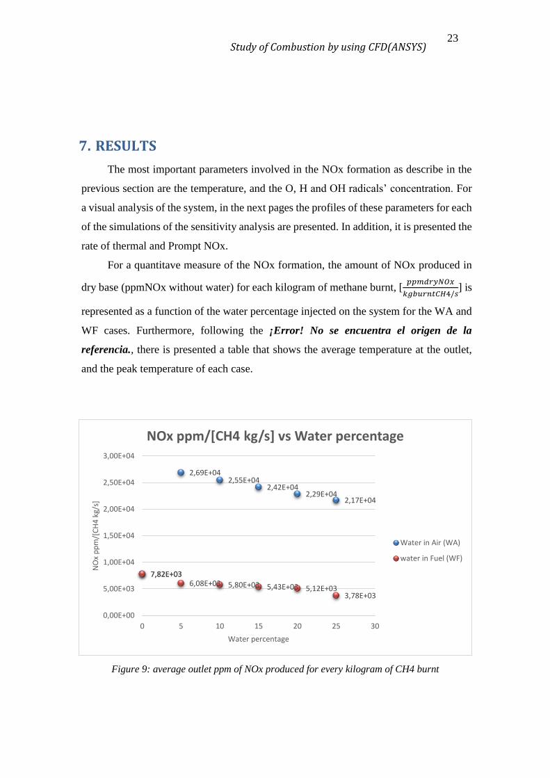
For a quantitave measure of the NOx formation, the amount of NOx produced in
dry base (ppmNOx without water) for each kilogram of methane burnt, [𝑝𝑝𝑚𝑑𝑟𝑦𝑁𝑂𝑥
𝑘𝑔𝑏𝑢𝑟𝑛𝑡𝐶𝐻4/𝑠] is
represented as a function of the water percentage injected on the system for the WA and
WF cases. Furthermore, following the ¡Error! No se encuentra el origen de la
referencia., there is presented a table that shows the average temperature at the outlet,
and the peak temperature of each case.
Figure 9: average outlet ppm of NOx produced for every kilogram of CH4 burnt
7,82E+03
2,69E+042,55E+04
2,42E+042,29E+04
2,17E+04
7,82E+036,08E+03 5,80E+03 5,43E+03 5,12E+03
3,78E+03
0,00E+00
5,00E+03
1,00E+04
1,50E+04
2,00E+04
2,50E+04
3,00E+04
0 5 10 15 20 25 30
NO
x p
pm
/[C
H4
kg/
s]
Water percentage
NOx ppm/[CH4 kg/s] vs Water percentage
Water in Air (WA)
water in Fuel (WF)
Study of Combustion by using CFD(ANSYS) 24
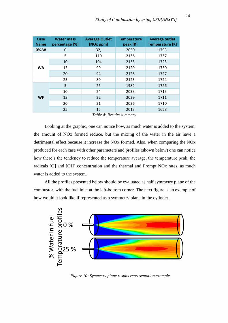
Case Name
Water mass percentage [%]
Average Outlet [NOx ppm]
Temperature peak [K]
Average outlet Temperature [K]
0%-W 0 32, 2050 1793
WA
5 110 2136 1737
10 104 2133 1723
15 99 2129 1730
20 94 2126 1727
25 89 2123 1724
WF
5 25 1982 1726
10 24 2033 1715
15 22 2029 1711
20 21 2026 1710
25 15 2013 1658
Table 4: Results summary
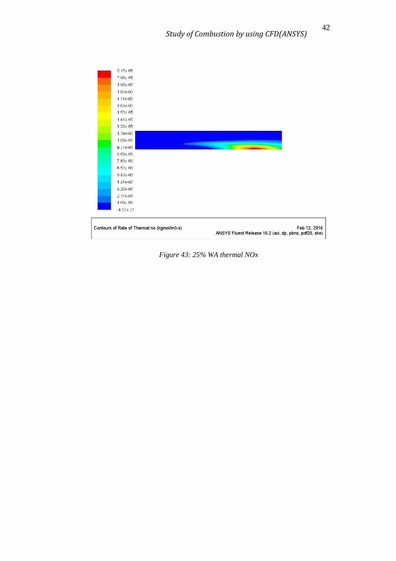
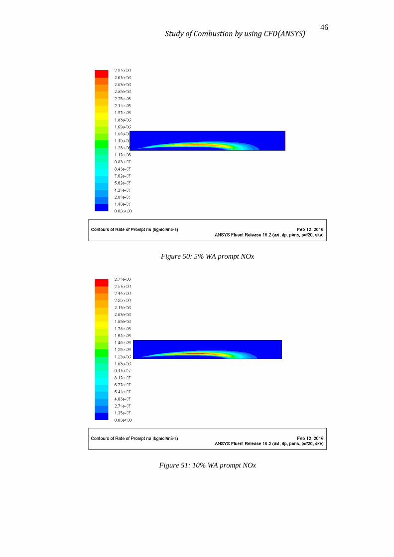
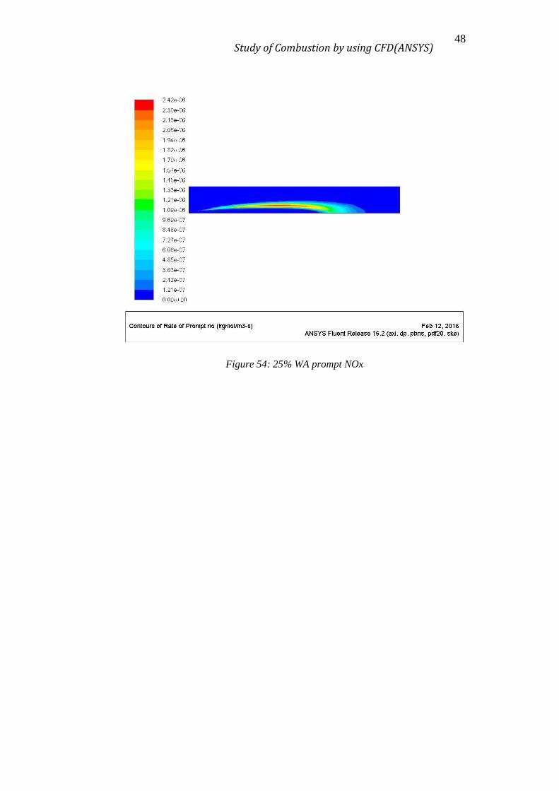
Looking at the graphic, one can notice how, as much water is added to the system,
the amount of NOx formed reduce, but the mixing of the water in the air have a
detrimental effect because it increase the NOx formed. Also, when comparing the NOx
produced for each case with other parameters and profiles (shown below) one can notice
how there’s the tendency to reduce the temperature average, the temperature peak, the
radicals [O] and [OH] concentration and the thermal and Prompt NOx rates, as much
water is added to the system.
All the profiles presented below should be evaluated as half symmetry plane of the
combustor, with the fuel inlet at the left-bottom corner. The next figure is an example of
how would it look like if represented as a symmetry plane in the cylinder.
Figure 10: Symmetry plane results representation example
Study of Combustion by using CFD(ANSYS) 25
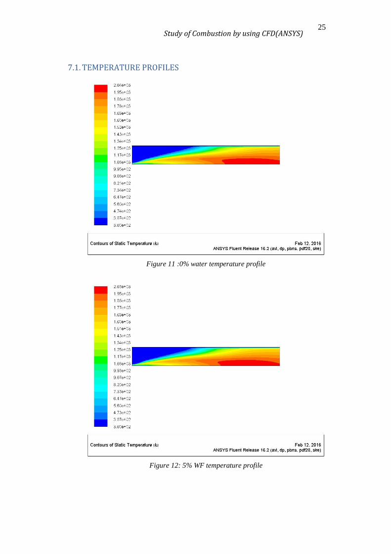
7.1. TEMPERATURE PROFILES
Figure 11 :0% water temperature profile
Figure 12: 5% WF temperature profile

Study of Combustion by using CFD(ANSYS) 26
Figure 13: 10% WF temperature profile
Figure 14: 15% WF temperature profile

Study of Combustion by using CFD(ANSYS) 27
Figure 15: 20 % WF temperature profile
Figure 16: 25 % WF temperature profile
Study of Combustion by using CFD(ANSYS) 28
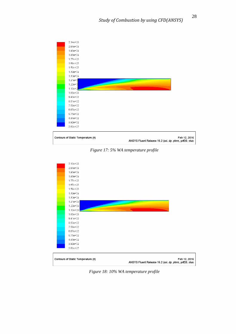
Figure 17: 5% WA temperature profile
Figure 18: 10% WA temperature profile

Study of Combustion by using CFD(ANSYS) 29
Figure 19: 15% WA temperature profile
Figure 20: 20% WA temperature profile

Study of Combustion by using CFD(ANSYS) 30
Figure 21: 25% WA temperature profile

Study of Combustion by using CFD(ANSYS) 31
7.2. NOX PPM PROFILES
Figure 22: 0% water ppmNOx
Figure 23: 5% WF ppmNOx
Study of Combustion by using CFD(ANSYS) 32
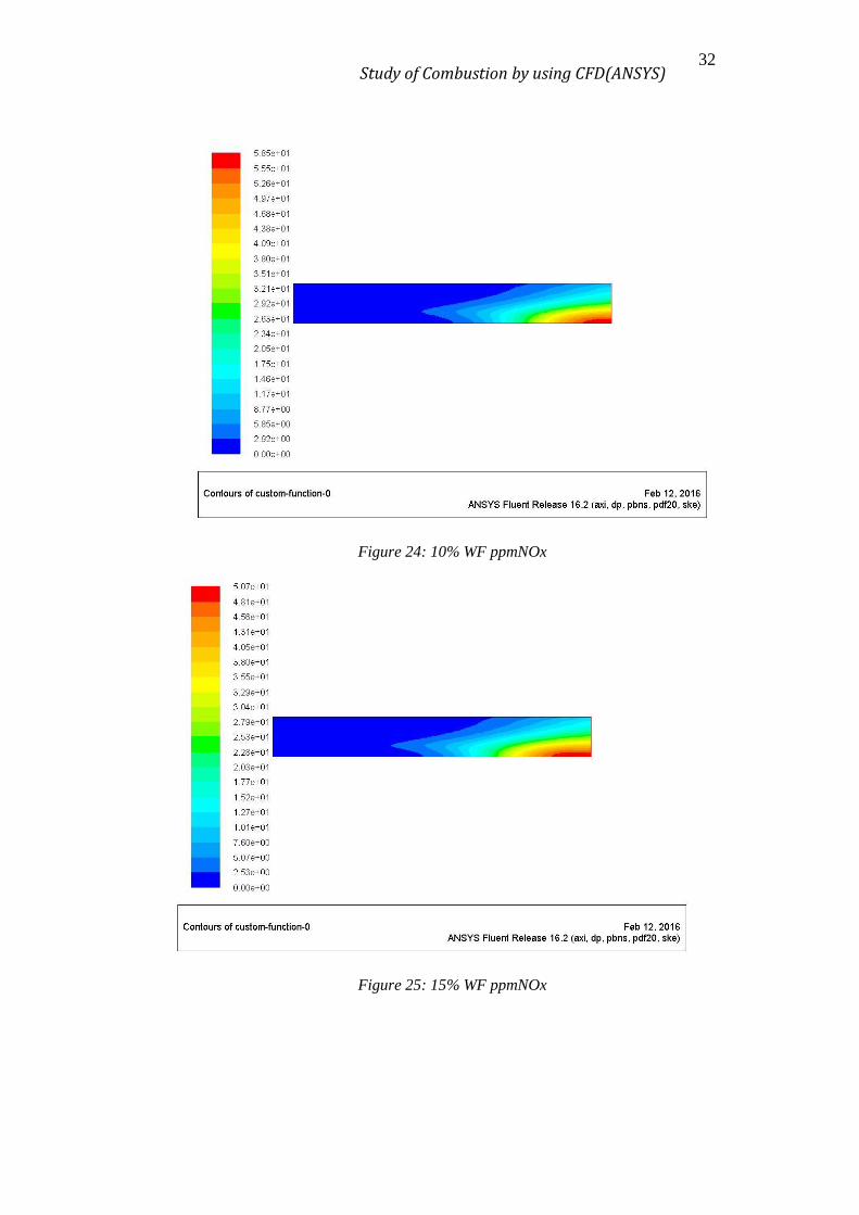
Figure 24: 10% WF ppmNOx
Figure 25: 15% WF ppmNOx

Study of Combustion by using CFD(ANSYS) 33
Figure 26: 20% WF ppmNOx
Figure 27: 25% WF ppmNOx
Study of Combustion by using CFD(ANSYS) 34
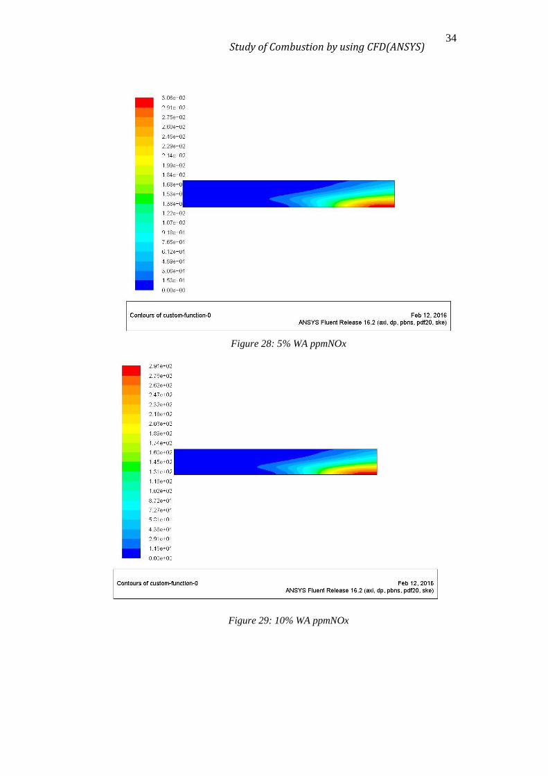
Figure 28: 5% WA ppmNOx
Figure 29: 10% WA ppmNOx

Study of Combustion by using CFD(ANSYS) 35
Figure 30: 15% WA ppmNOx
Figure 31: 20% WA ppmNOx
Study of Combustion by using CFD(ANSYS) 36
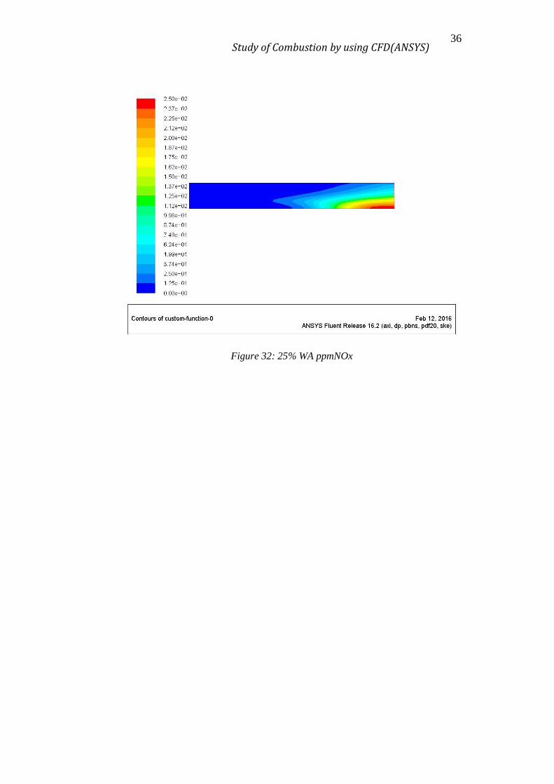
Figure 32: 25% WA ppmNOx

Study of Combustion by using CFD(ANSYS) 37
7.3. THERMAL NOX RATE PROFILES
Figure 33: 0% water thermal NOx
Figure 34: 5% WF thermal NOx

Study of Combustion by using CFD(ANSYS) 38
Figure 35: 10% WF thermal NOx
Figure 36: 15% WF thermal NOx

Study of Combustion by using CFD(ANSYS) 39
Figure 37: 20% WF thermal NOx
Figure 38: 25% WF thermal NOx
Study of Combustion by using CFD(ANSYS) 40
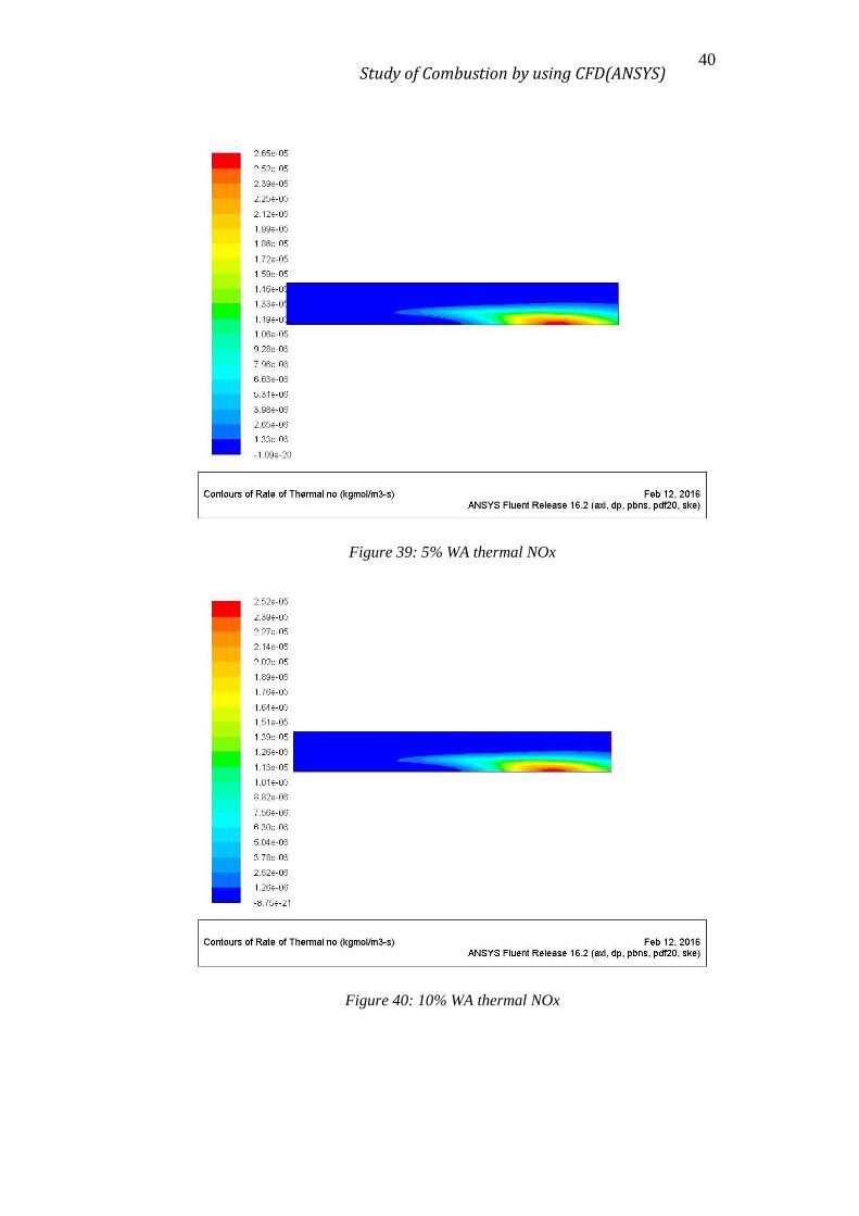
Figure 39: 5% WA thermal NOx
Figure 40: 10% WA thermal NOx

Study of Combustion by using CFD(ANSYS) 41
Figure 41: 15% WA thermal NOx
Figure 42: 20% WA thermal NOx
Study of Combustion by using CFD(ANSYS) 42
Figure 43: 25% WA thermal NOx

Study of Combustion by using CFD(ANSYS) 43
7.4. PROMP NOX RATE PROFILES
Figure 44: 0% water prompt NOx
Figure 45: 5% WF prompt NOx

Study of Combustion by using CFD(ANSYS) 44
Figure 46: 10% WF prompt NOx
Figure 47: 15% WF prompt NOx

Study of Combustion by using CFD(ANSYS) 45
Figure 48: 20% WF prompt NOx
Figure 49: 25% WF prompt NOx
Study of Combustion by using CFD(ANSYS) 46
Figure 50: 5% WA prompt NOx
Figure 51: 10% WA prompt NOx

Study of Combustion by using CFD(ANSYS) 47
Figure 52: 15% WA prompt NOx
Figure 53: 20% WA prompt NOx
Study of Combustion by using CFD(ANSYS) 48
Figure 54: 25% WA prompt NOx

Study of Combustion by using CFD(ANSYS) 49
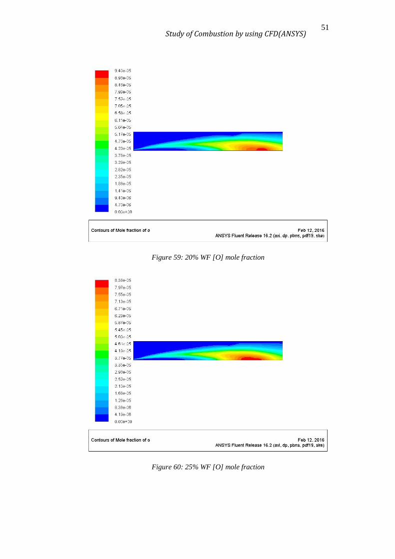
7.5. RADICAL [O] PROFILES
Figure 55: 0% water [O] mole fraction
Figure 56: 5% WF [O] mole fraction

Study of Combustion by using CFD(ANSYS) 50
Figure 57: 10% WF [O] mole fraction
Figure 58: 15% WF [O] mole fraction
Study of Combustion by using CFD(ANSYS) 51
Figure 59: 20% WF [O] mole fraction
Figure 60: 25% WF [O] mole fraction

Study of Combustion by using CFD(ANSYS) 52
Figure 61: 5% WA [O] mole fraction
Figure 62: 10% WA [O] mole fraction

Study of Combustion by using CFD(ANSYS) 53
Figure 63: 15% WA [O] mole fraction
Figure 64: 20% WA [O] mole fraction
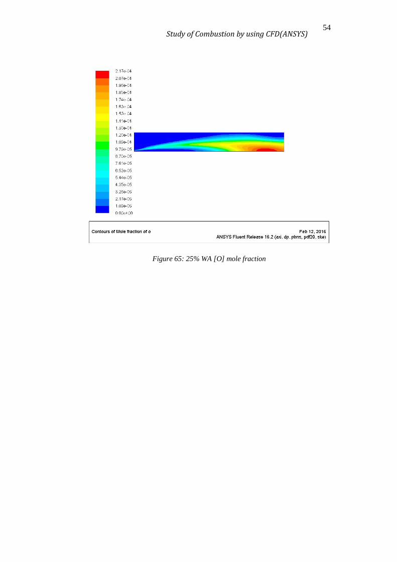
Study of Combustion by using CFD(ANSYS) 54
Figure 65: 25% WA [O] mole fraction
Study of Combustion by using CFD(ANSYS) 55
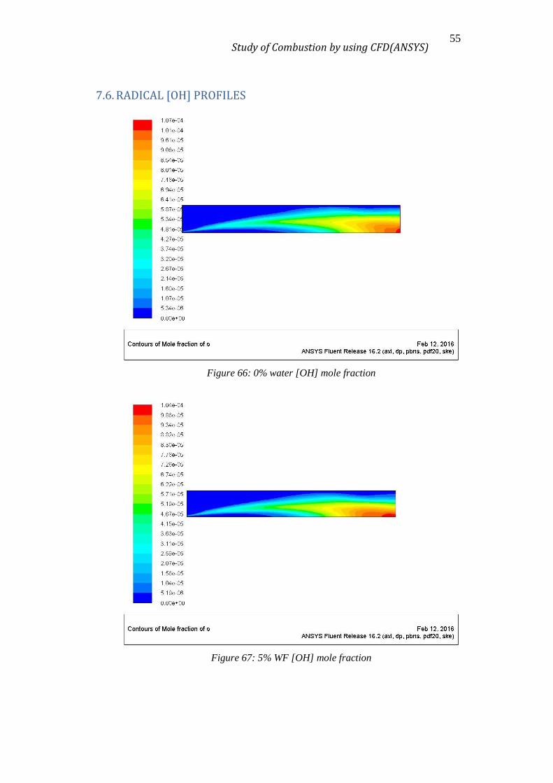
7.6. RADICAL [OH] PROFILES
Figure 66: 0% water [OH] mole fraction
Figure 67: 5% WF [OH] mole fraction

Study of Combustion by using CFD(ANSYS) 56
Figure 68: 10% WF [OH] mole fraction
Figure 69: 15% WF [OH] mole fraction
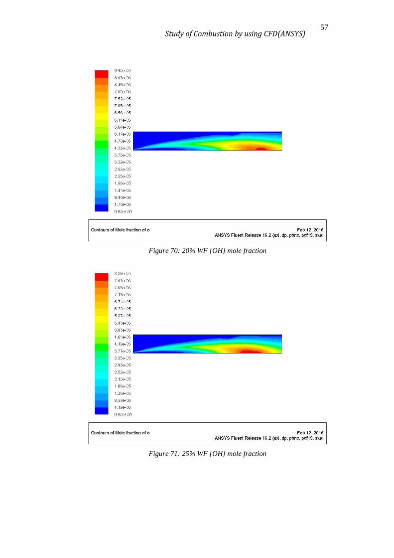
Study of Combustion by using CFD(ANSYS) 57
Figure 70: 20% WF [OH] mole fraction
Figure 71: 25% WF [OH] mole fraction

Study of Combustion by using CFD(ANSYS) 58
Figure 72: 5% WA [OH] mole fraction
Figure 73: 10% WA [OH] mole fraction
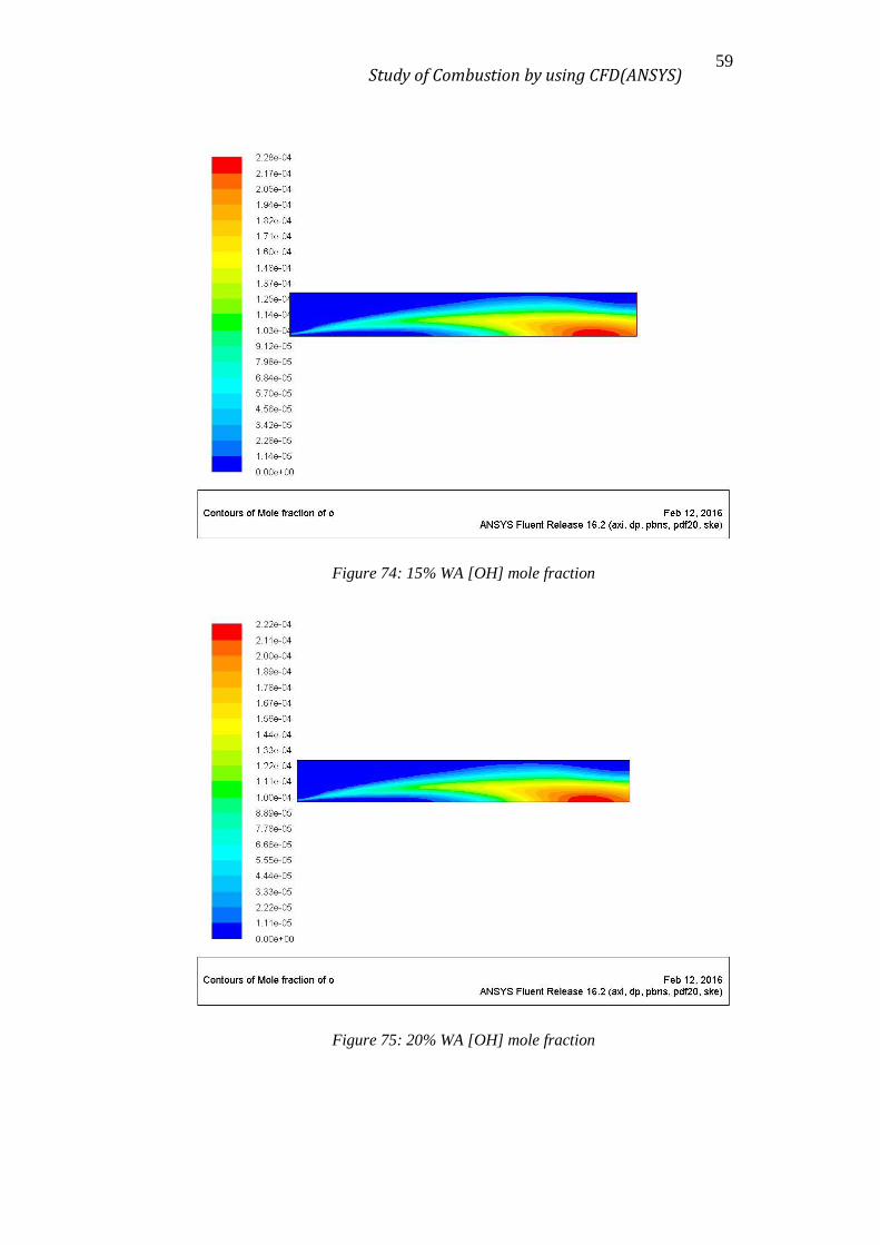
Study of Combustion by using CFD(ANSYS) 59
Figure 74: 15% WA [OH] mole fraction
Figure 75: 20% WA [OH] mole fraction

Study of Combustion by using CFD(ANSYS) 60
Figure 76: 25% WA [OH] mole fraction

Study of Combustion by using CFD(ANSYS) 61
8. CONCLUSIONS
After all the work done, the results show pretty interesting results. It is clear that
the addition of water have a significant effect on the NOx formation. Independently of
the contact mode, as more water is added to the system, less NOx are formed. This is
supposed to be because of some reasons:
First, the addition of water has a direct effect in the temperature profile of the
system. It reduce the peak temperature and also the average temperature of the system,
what implies a reduction of the thermal NOx (which are the main contributors to the total
NOx as can be observed from the profiles).
Secondly, as can be observed in the profiles, the concentration of both radicals [O]
and [OH] is reduced as more water is added, what influences the equilibrium reactions
implied in the formation of NO and NO2.
Another interesting conclusion is that, if this process is not correctly done, the
addition of water will have a detrimental effect of the system. This can be notice from
the Figure 9, whereas the addition to the Fuel stream reduce the NOx formed in
comparison with the non-water case, the addition of water to the Air stream causes an
increment in the NOx formed in the system (it causes an increment of the average
temperature and radicals concentration). This a clear example of how important it is the
contact mode when performing any chemical reaction.
This work gives the tendency of the NOx formation when adding water to the
system, but the reaction mechanism, the radiation model and other system’ parameters
used for the simulations are quite simple, so the results must be taken, as this is, a
tendency.
Study of Combustion by using CFD(ANSYS) 62
9. FUTURE WORK
As commented in the conclusions, the models used for this work are very simple.
For a more accurate study, it’s recommended to implement more detailed models
regarding to species transport, kinetics (for instance GRI 3.0(10)), radiation and contours
(i.e. walls).
In addition, it would be very interesting to compare the simulations with an
experimental assay to validate the models used in the study. However, one must take into
account that this works implies much more time than the available for a master thesis,
e.g. a PhD would be required. System selection and apparatus montage, and detailed
modelling and calculations implies lots of time, but would be worth spent if these studies
carry innovation and solutions for the problematic issue of NOx pollution.
Study of Combustion by using CFD(ANSYS) 63
REFERENCES
1. Byeonghun Yu; Seungro Lee; Chang-Eon Lee. Study of NOx emission
characteristics in CH4/air non-premixed flames with exhaust gas recirculation.
ELSEVIER Energy, Volume 91, November 2015, pp 119-127.
2. Leszek Chybowski; Rafał Laskowski; Katarzyna Gawdzinska. An overview of
systems supplying water into the combustion chamber of diesel engines to
decrease the amount of nitrogen oxides in exhaust gas. Japan society of Naval
Architects and Ocean Engineers-Journal, January 2015 Review
3. C.E.L. Pinho; J.M.P.Q. Delgado; R. Pilão; J. Conde; C. Pinho2, Numerical Study
of Propane-Air Mixture Combustion in a Burner Element,Defect and Diffusion
Forum Vols. 273-276 ,2008 pp 144-149
4. Julio Rendón; Francisco Cadavid; Andrés Amell. Flame structure simulation in a
methane/air co-flow partially premixed burner. Fac. Ing. Univ. Antioquia ,Junio
2008, N.° 44. pp. 61-74.
5. M.M.Noor; Andrew P.Wandel1; Talal Yusaf. Detail guide for CFD on the
Simulation of Biogas Combustion in Bluff-Body Mild Burner. International
Conference on Mechanical Engineering Research. July 2013. Paper ID: P342
6. ANSYS Tutorial (2015); FLUENT Tutorial guide. ANSYS, Inc. Release: 16.0,
January 2015
7. ANSYS Theory (2015) ANSYS FLUENT Theory guide. ANSYS, Inc. Release:
16.2, July 2015
8. http://www.telegraph.co.uk/finance/newsbysector/transport/11463519/Car-
industry-fumes-about-the-demonisation-of-diesel-engines.html (New about
Europe concern in the NOx’s pollution) Visited January 2016
9. http://combustion.berkeley.edu/gri-mech/version30/text30.html (Combustion
mechanism with NOx considerations: GRI 3.0). Visited: January 2016
10. http://territori.gencat.cat/ca/01_departament/11_normativa_i_documentacio/
(Legislation website of Catalonia territory) Visited January 2016


![INDEX [eel.upc.edu]...Estudiantat visitant . Berk Çelik Estudiant de Màster de la Ege University, Izmir, Turquia. Tipus estada: Tesi de Màster. Durada: 6 mesos](https://img.pdfslide.us/doc/110x75/5f0a4cd27e708231d42afabb/index-eelupcedu-estudiantat-visitant-berk-elik-estudiant-de-mster.jpg)