Embed Size (px)
Citation preview
t-A-Glance
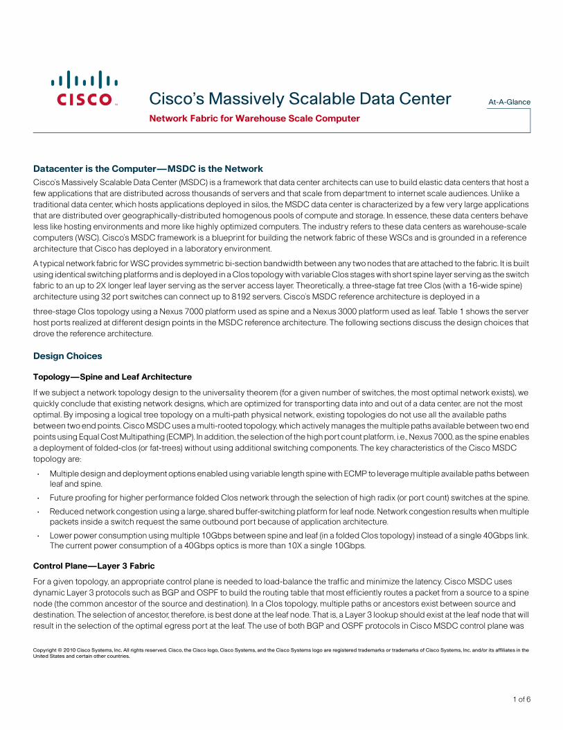
ACisco’s Massively Scalable Data CenterNetwork Fabric for Warehouse Scale ComputerDatacenter is the Computer—MSDC is the NetworkCisco’s Massively Scalable Data Center (MSDC) is a framework that data center architects can use to build elastic data centers that host a few applications that are distributed across thousands of servers and that scale from department to internet scale audiences. Unlike a traditional data center, which hosts applications deployed in silos, the MSDC data center is characterized by a few very large applications that are distributed over geographically-distributed homogenous pools of compute and storage. In essence, these data centers behave less like hosting environments and more like highly optimized computers. The industry refers to these data centers as warehouse-scale computers (WSC). Cisco’s MSDC framework is a blueprint for building the network fabric of these WSCs and is grounded in a reference architecture that Cisco has deployed in a laboratory environment.
A typical network fabric for WSC provides symmetric bi-section bandwidth between any two nodes that are attached to the fabric. It is built using identical switching platforms and is deployed in a Clos topology with variable Clos stages with short spine layer serving as the switch fabric to an up to 2X longer leaf layer serving as the server access layer. Theoretically, a three-stage fat tree Clos (with a 16-wide spine) architecture using 32 port switches can connect up to 8192 servers. Cisco’s MSDC reference architecture is deployed in a
three-stage Clos topology using a Nexus 7000 platform used as spine and a Nexus 3000 platform used as leaf. Table 1 shows the server host ports realized at different design points in the MSDC reference architecture. The following sections discuss the design choices that drove the reference architecture.
Design Choices
Topology—Spine and Leaf Architecture
If we subject a network topology design to the universality theorem (for a given number of switches, the most optimal network exists), we quickly conclude that existing network designs, which are optimized for transporting data into and out of a data center, are not the most optimal. By imposing a logical tree topology on a multi-path physical network, existing topologies do not use all the available paths between two end points. Cisco MSDC uses a multi-rooted topology, which actively manages the multiple paths available between two end points using Equal Cost Multipathing (ECMP). In addition, the selection of the high port count platform, i.e., Nexus 7000, as the spine enables a deployment of folded-clos (or fat-trees) without using additional switching components. The key characteristics of the Cisco MSDC topology are:
• Multiple design and deployment options enabled using variable length spine with ECMP to leverage multiple available paths between leaf and spine.
• Future proofing for higher performance folded Clos network through the selection of high radix (or port count) switches at the spine.
• Reduced network congestion using a large, shared buffer-switching platform for leaf node. Network congestion results when multiple packets inside a switch request the same outbound port because of application architecture.
• Lower power consumption using multiple 10Gbps between spine and leaf (in a folded Clos topology) instead of a single 40Gbps link. The current power consumption of a 40Gbps optics is more than 10X a single 10Gbps.
Control Plane—Layer 3 Fabric
For a given topology, an appropriate control plane is needed to load-balance the traffic and minimize the latency. Cisco MSDC uses dynamic Layer 3 protocols such as BGP and OSPF to build the routing table that most efficiently routes a packet from a source to a spine node (the common ancestor of the source and destination). In a Clos topology, multiple paths or ancestors exist between source and destination. The selection of ancestor, therefore, is best done at the leaf node. That is, a Layer 3 lookup should exist at the leaf node that will result in the selection of the optimal egress port at the leaf. The use of both BGP and OSPF protocols in Cisco MSDC control plane was
Copyright © 2010 Cisco Systems, Inc. All rights reserved. Cisco, the Cisco logo, Cisco Systems, and the Cisco Systems logo are registered trademarks or trademarks of Cisco Systems, Inc. and/or its affiliates in the United States and certain other countries.
1 of 6
At-A-Glance Cisco’s Massively Scalable Data Center
driven by the need to sustain performance as the network scales from a few thousand nodes to a few hundred thousand nodes. Using the optimal routing architecture minimizes the congestion in the network by reducing packet collision when multiple packets head for the same egress port. The key characteristics of the Cisco MSDC control plane are:
• Use of BGP to advertise reachability and OSPF to determine the shortest path to it. Optimal execution of both protocol stacks to reduce router CPU and memory utilization.
• Layer 3 look up at every hop to optimize the selection of the spine node reducing latency and avoiding congestion. It has the additional advantage of not exhausting a scarce resource: the leaf’s forwarding table.
• The current architecture serves as a good platform to add future application-specific optimizations through this selection.
Monitoring and MaintenanceCisco MSDC framework and reference architecture deals with the issue of monitoring, managing, and maintaining a large network through minimal use of SNMP-based infrastructure for monitoring and management. The management framework prefers the use of an agentless monitoring system that scales to thousands of nodes. The key characteristics of the Cisco MSDC monitoring and maintenance plane are:
• Use of Ganglia for monitoring host infrastructure through collection of metrics and trends. Customization of monitoring using Python extension mechanism to Ganglia. Like many other open source and proprietary tools, Ganglia uses RRDTool for graphics.
• Use of Ganglia extension mechanism for in-band plugins to deploy custom python modules to monitor the host environment.
• Use of Nagios to monitor network infrastructure and resource managers. Use of Nagios’s built-in mechanism to alert on Ganglia metrics.
Future—Programmability and Network Overlays
Cisco MSDC architecture does not preclude the future use of an external or built-in controller that could populate the forwarding table at the spine or leaf nodes to introduce adaptive or deterministic load balancing or routing. Using the Layer 3 control plane offers the large advantage of reducing the state that a switch holds. This offers immense help to an external control by reducing the amount of sync traffic between controller and infrastructure. Network overlay initiatives are attempting to remove the one shortcoming of a Layer 3 control plane, which is a Layer 2 extension model for the developers. Cisco’s MSDC framework can be adapted easily to work with any network overlay technology that crosses the chasm.
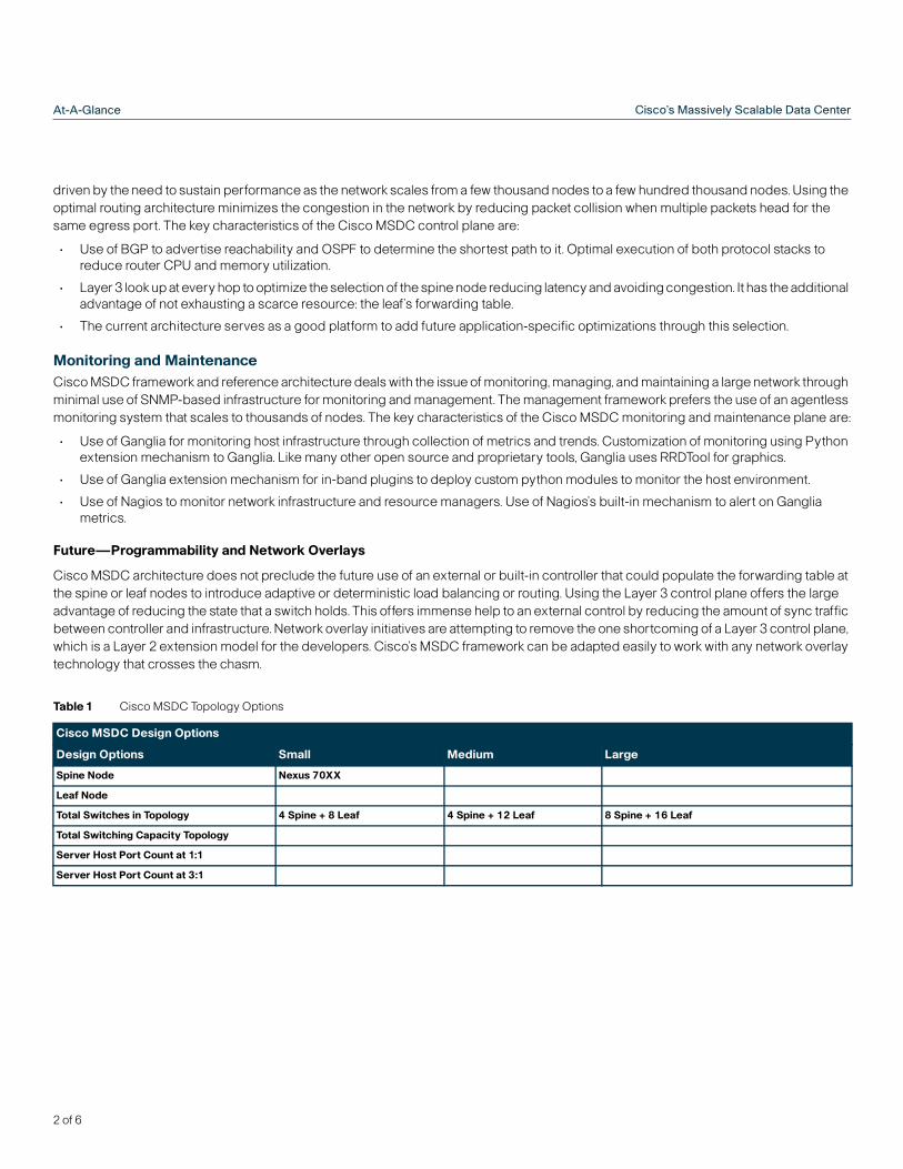
Table 1 Cisco MSDC Topology Options
Cisco MSDC Design Options
Design Options Small Medium Large
Spine Node Nexus 70XX
Leaf Node
Total Switches in Topology 4 Spine + 8 Leaf 4 Spine + 12 Leaf 8 Spine + 16 Leaf
Total Switching Capacity Topology
Server Host Port Count at 1:1
Server Host Port Count at 3:1
2 of 6
At-A-GlanceCisco’s Massively Scalable Data Center
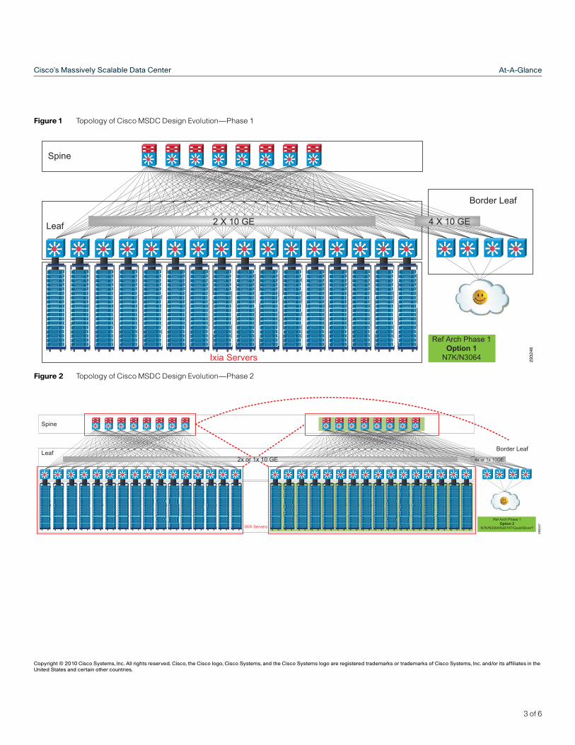
Figure 1 Topology of Cisco MSDC Design Evolution—Phase 1
Figure 2 Topology of Cisco MSDC Design Evolution—Phase 2
Ixia Servers
Leaf
Spine
Border Leaf
Ref Arch Phase 1Option 1N7K/N3064
2 X 10 GE 4 X 10 GE
2932
46
Copyright © 2010 Cisco Systems, Inc. All rights reserved. Cisco, the Cisco logo, Cisco Systems, and the Cisco Systems logo are registered trademarks or trademarks of Cisco Systems, Inc. and/or its affiliates in the United States and certain other countries.
IXIA Servers
Leaf
Spine
Border Leaf
Ref Arch Phase 1Option 2
N7K/N3064/N3016?/QuickSilver?
4x or 1x 10GE2x or 1x 10 GE
2932
47
3 of 6
At-A-Glance Cisco’s Massively Scalable Data Center
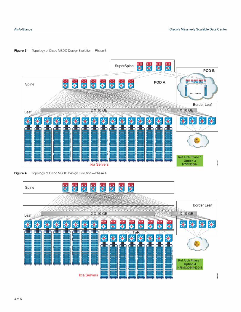
Figure 3 Topology of Cisco MSDC Design Evolution—Phase 3
Figure 4 Topology of Cisco MSDC Design Evolution—Phase 4
Ixia Servers
Leaf
Spine
Border Leaf
Ref Arch Phase 1Option 3N7K/N3064
2 X 10 GE 4 X 10 GE
SuperSpine
POD A
POD B
…………..
.
.
.
2932
48
Ixia Servers
Leaf
Spine
Border Leaf
Ref Arch Phase 1Option 4
N7K/N3064/N3048
2 X 10 GE 4 X 10 GE
ToR
2932
49
4 of 6
At-A-GlanceCisco’s Massively Scalable Data Center
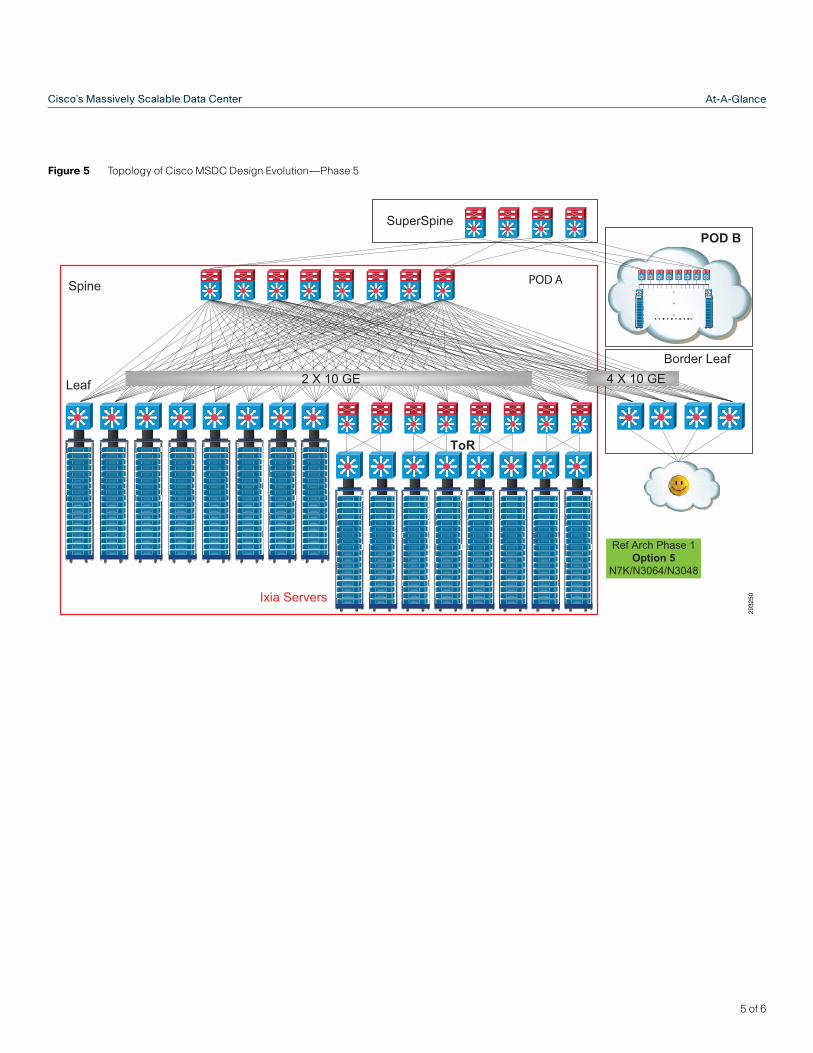
Figure 5 Topology of Cisco MSDC Design Evolution—Phase 5
Ixia Servers
Leaf
Spine
Ref Arch Phase 1Option 5
N7K/N3064/N3048
2 X 10 GE 4 X 10 GE
ToR
SuperSpine
POD A
POD B
…………..
.
.
.
Border Leaf
2932
50
5 of 6
At-A-Glance Cisco’s Massively Scalable Data Center
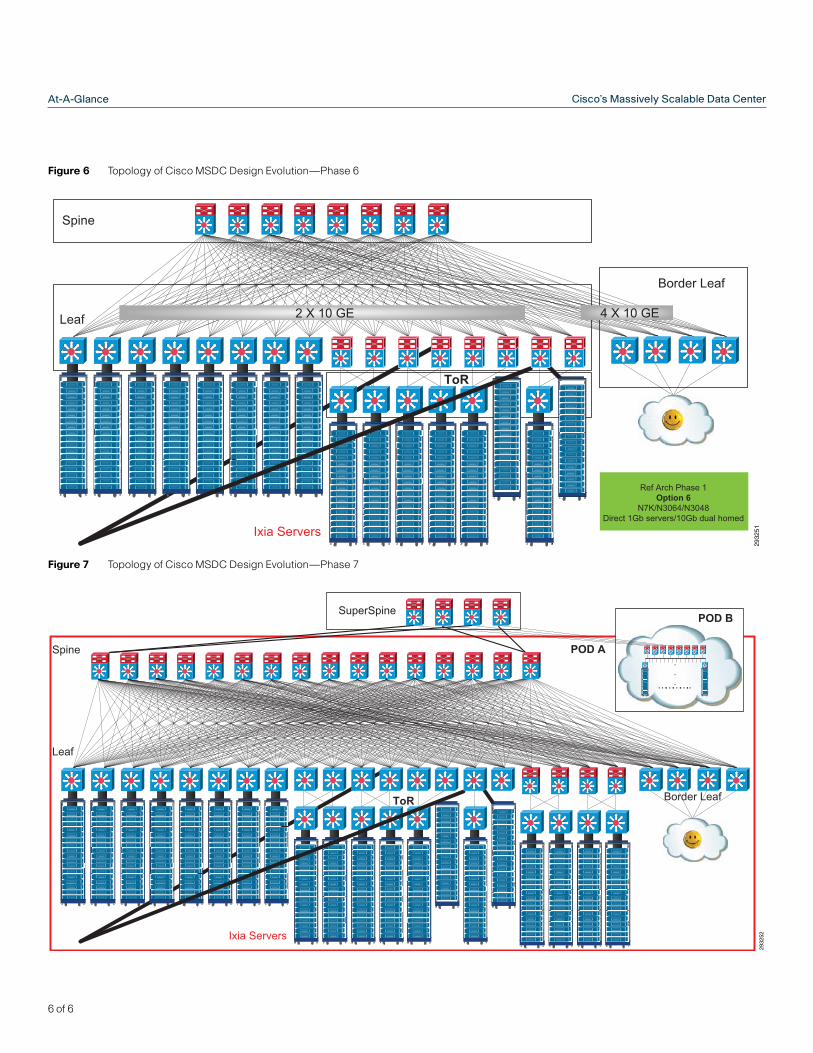
Figure 6 Topology of Cisco MSDC Design Evolution—Phase 6
Figure 7 Topology of Cisco MSDC Design Evolution—Phase 7
Ixia Servers
Leaf
Spine
Border Leaf
Ref Arch Phase 1Option 6
N7K/N3064/N3048Direct 1Gb servers/10Gb dual homed
2 X 10 GE 4 X 10 GE
ToR
2932
51
Ixia Servers
Leaf
Spine
Border LeafToR
SuperSpine
POD A
POD B
…………..
.
.
.
2932
52
6 of 6