Embed Size (px)
Citation preview
1 | P a g e
MASSIVE MIMO TECHNOLOGY FOR VISIBLE
LIGHT COMMUNICATION (VLC)
Amar Prakash Jyoti1, Dr.Sumita Mishra
2
1, 2 Department of Electronics and Communication, Amity University, Lucknow (U.P)
ABSTRACT
Visible Light Communications (VLC), and the idea of using LEDs for both illumination and data
communications The main drivers for this technology include the increasing popularity of solid-state lighting,
longer lifetime of high-brightness LEDs associated to additional sources of simulated light like the incandescent
light bulbs, high bandwidth/data rate, data security, no health hazards and low power consumption The dual
functionality provided by VLC (i.e., lighting and data communication from the same high-brightness LEDs) has
created a whole range of interesting applications, including but not imperfect to home networking, high rapidity
data communication through lighting infrastructures in offices, car-to-car communication, high-speed
communication in aeroplane cabins, in-trains data communication, traffic lights management and
communications to name a few The levels of power efficiency and reliability offered by LEDs today are by far
superior compared to the traditional incandescent light sources used for lighting. Recent research in VLC has
successfully established data transmission at over 500 Mbps over short links in office and home environments
Further research and developments will open up new possibilities to partly resolve some of the issues associated
with the present-day infrared, radio/microwave communication systems and lighting technologies.
I INTRODUCTION
In this paper, visible light communication (VLC) is a subset of optical wireless communication technologies.
The technology procedures luminous lamps (conventional lamps, not special communication devices) to
transmit signal at or LEDs for up to . Visible light communication (VLC) is a data
communication medium which uses visible light between It
is used as a very small range of optical wireless communication (OWC) operating light emitting diode (LED)
lighting. So that the LED can provide both illumination and communication[1].
Low rate data transmission at 1 and 2 . VLC can be used as a communication medium
for universal computing, because light producing devices (such as indoor and outdoor , TVs, Traffic signs,
commercial displays and car head light/ tail light) are used everywhere.
The phenomenon in optoelectronics i.e., solid state light sources which is refers to the fact that light is generated
through solid state electroluminescence. In 1990s, An introduction of another upcoming type of solid-state
lighting source, known as the organic LED (OLED) OLED has relatively low luminous effectiveness (measured
value of 100 lm/W and short lifetime compared with the LEDs, thuslimiting their application for various colour
140 | P a g e
displays and general illumination for thetime being Nevertheless, OLEDs may also be used as an alternative
solution forlarge area lighting and communications[2].
Visible Light Communications (VLC) has establishedconsiderablycurrent attention done overdisplays as LiFi
and IEEE 802.15.4. As a ―smart lighting‖ paradigm, it has received significant interest by the scientific
community since this new paradigm may be used for sensing, localization and data communication, in
accumulation to the common lighting application. The main article of VLC is its potential for ―double usage‖,
providing both lighting and high speed information access. This aspect brings to several advantages that make
VLC ainordinatesupplement to Radio-Frequency (RF) communications. Certainly, while exploiting the free use
of the visible light spectrum, VLC usages the indicator of optical transmissions, and can offer secure
transmissions.
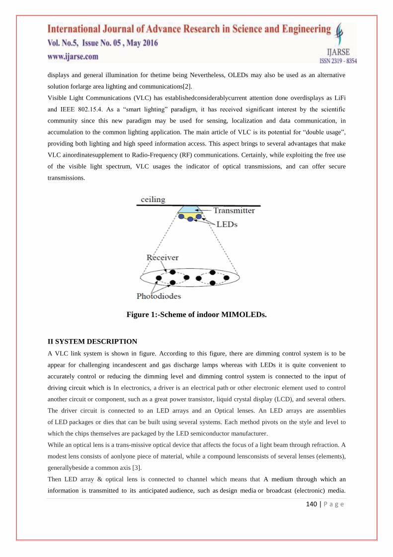
Figure 1:-Scheme of indoor MIMOLEDs.
II SYSTEM DESCRIPTION
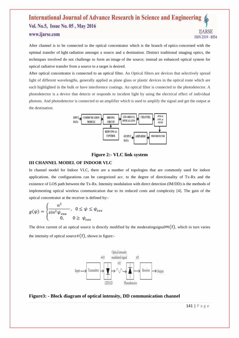
A VLC link system is shown in figure. According to this figure, there are dimming control system is to be
appear for challenging incandescent and gas discharge lamps whereas with LEDs it is quite convenient to
accurately control or reducing the dimming level and dimming control system is connected to the input of
driving circuit which is In electronics, a driver is an electrical path or other electronic element used to control
another circuit or component, such as a great power transistor, liquid crystal display (LCD), and several others.
The driver circuit is connected to an LED arrays and an Optical lenses. An LED arrays are assemblies
of LED packages or dies that can be built using several systems. Each method pivots on the style and level to
which the chips themselves are packaged by the LED semiconductor manufacturer.
While an optical lens is a trans-missive optical device that affects the focus of a light beam through refraction. A
modest lens consists of aonlyone piece of material, while a compound lensconsists of several lenses (elements),
generallybeside a common axis [3].
Then LED array & optical lens is connected to channel which means that A medium through which an
information is transmitted to its anticipated audience, such as design media or broadcast (electronic) media.
141 | P a g e
After channel is to be connected to the optical concentrator which is the branch of optics concerned with the
optimal transfer of light radiation amongst a source and a destination. Distinct traditional imaging optics, the
techniques involved do not challenge to form an image of the source; instead an enhanced optical system for
optical radiative transfer from a source to a target is desired.
After optical concentrator is connected to an optical filter. An Optical filters are devices that selectively spread
light of different wavelengths, generally applied as plane glass or plastic devices in the optical route which are
each highlighted in the bulk or have interference coatings. An optical filter is connected to the photodetector. A
photodetector is a device that detects or responds to incident light by using the electrical effect of individual
photons. And photodetector is connected to an amplifier which is used to amplify the signal and get the output at
the destination.
Figure 2:- VLC link system
III CHANNEL MODEL OF INDOOR VLC
In channel model for Indoor VLC, there are a number of topologies that are commonly used for indoor
applications. the configurations can be categorized acc. to the degree of directionality of Tx-Rx and the
existence of LOS path between the Tx-Rx. Intensity modulation with direct detection (IM/DD) is the methods of
implementing optical wireless communication due to its reduced costs and complexity [4]. The gain of the
optical concentrator at the receiver is defined by:-
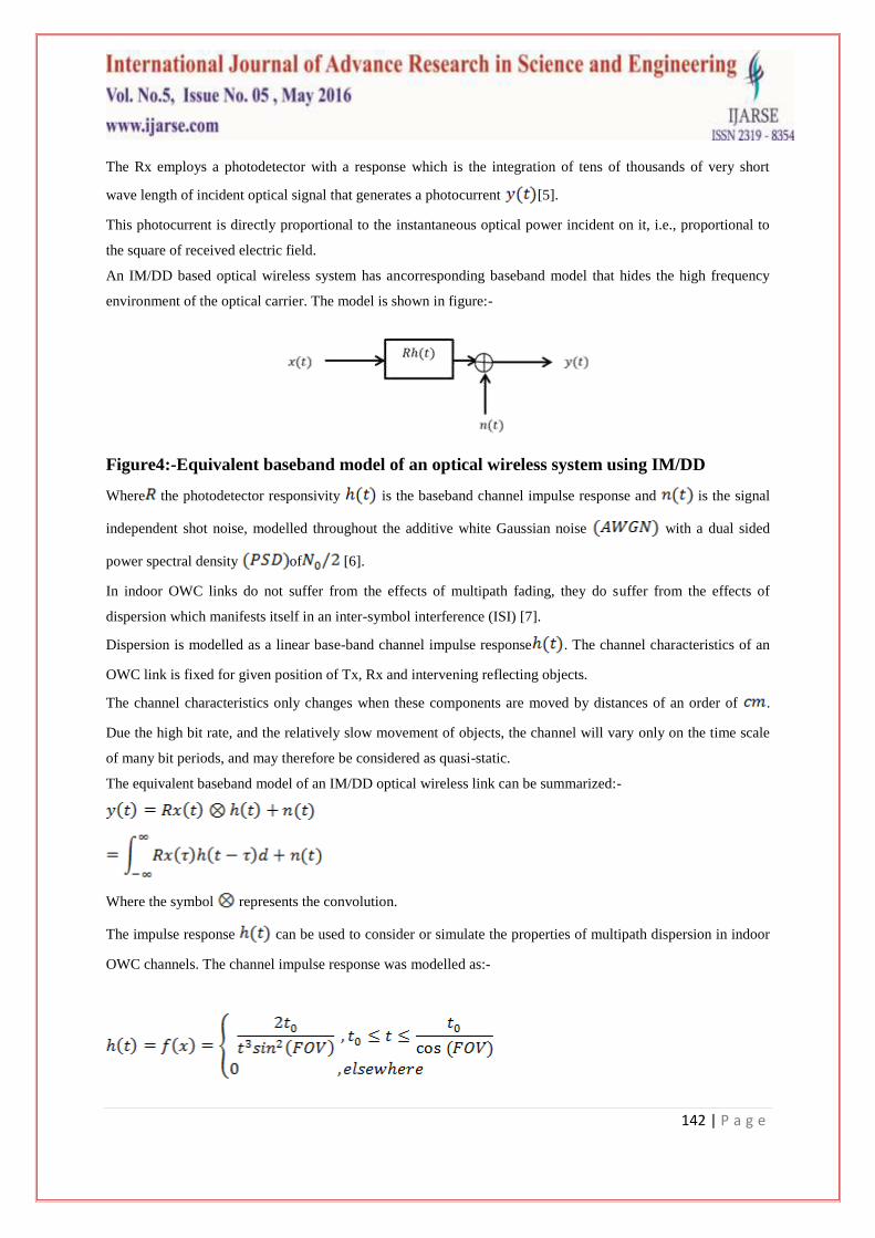
The drive current of an optical source is directly modified by the moderatingsignal , which in turn varies
the intensity of optical source , shown in figure:-
Figure3: - Block diagram of optical intensity, DD communication channel
142 | P a g e
The Rx employs a photodetector with a response which is the integration of tens of thousands of very short
wave length of incident optical signal that generates a photocurrent [5].
This photocurrent is directly proportional to the instantaneous optical power incident on it, i.e., proportional to
the square of received electric field.
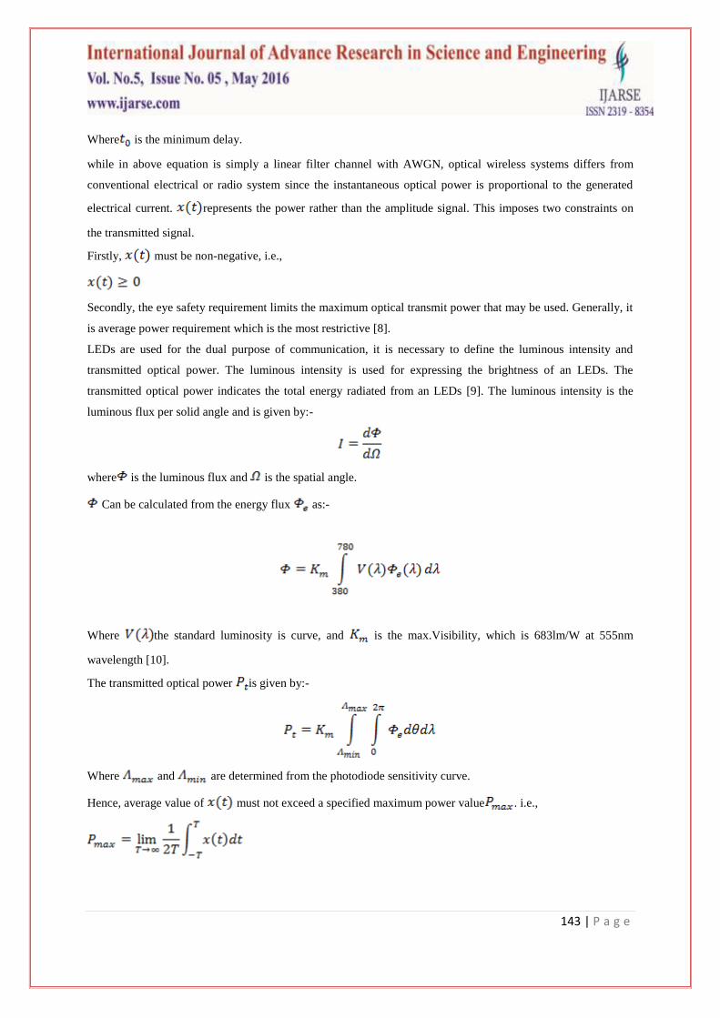
An IM/DD based optical wireless system has ancorresponding baseband model that hides the high frequency
environment of the optical carrier. The model is shown in figure:-
Figure4:-Equivalent baseband model of an optical wireless system using IM/DD
Where the photodetector responsivity is the baseband channel impulse response and is the signal
independent shot noise, modelled throughout the additive white Gaussian noise with a dual sided
power spectral density of [6].
In indoor OWC links do not suffer from the effects of multipath fading, they do suffer from the effects of
dispersion which manifests itself in an inter-symbol interference (ISI) [7].
Dispersion is modelled as a linear base-band channel impulse response . The channel characteristics of an
OWC link is fixed for given position of Tx, Rx and intervening reflecting objects.
The channel characteristics only changes when these components are moved by distances of an order of .
Due the high bit rate, and the relatively slow movement of objects, the channel will vary only on the time scale
of many bit periods, and may therefore be considered as quasi-static.
The equivalent baseband model of an IM/DD optical wireless link can be summarized:-
Where the symbol represents the convolution.
The impulse response can be used to consider or simulate the properties of multipath dispersion in indoor
OWC channels. The channel impulse response was modelled as:-
143 | P a g e
Where is the minimum delay.
while in above equation is simply a linear filter channel with AWGN, optical wireless systems differs from
conventional electrical or radio system since the instantaneous optical power is proportional to the generated
electrical current. represents the power rather than the amplitude signal. This imposes two constraints on
the transmitted signal.
Firstly, must be non-negative, i.e.,
Secondly, the eye safety requirement limits the maximum optical transmit power that may be used. Generally, it
is average power requirement which is the most restrictive [8].
LEDs are used for the dual purpose of communication, it is necessary to define the luminous intensity and
transmitted optical power. The luminous intensity is used for expressing the brightness of an LEDs. The
transmitted optical power indicates the total energy radiated from an LEDs [9]. The luminous intensity is the
luminous flux per solid angle and is given by:-
where is the luminous flux and is the spatial angle.
Can be calculated from the energy flux as:-
Where the standard luminosity is curve, and is the max.Visibility, which is 683lm/W at 555nm
wavelength [10].
The transmitted optical power is given by:-
Where and are determined from the photodiode sensitivity curve.
Hence, average value of must not exceed a specified maximum power value . i.e.,
144 | P a g e
This is in contrast to the time averaged value of the signal , which is the case for the conventional RF
channel when represents amplitude [11].
III MODULATION TECHNIQUE OF INDOOR VLC
In the modulation of indoor visible light communication, both quadrature amplitude modulation (QAM) on
discrete multi-tones (DMT) and multi-level pulse amplitude modulation (PAM) schemes is suitable for LEDs
based communication but are less power efficient [12].
DMT is a baseband implementation of the more universal orthogonal frequency division multiplexing (OFDM)
and most useful for channels with interferences or strong small frequency noise due to the synthetic ambient
light sources (e.g., fluorescent and incandescent) [13].
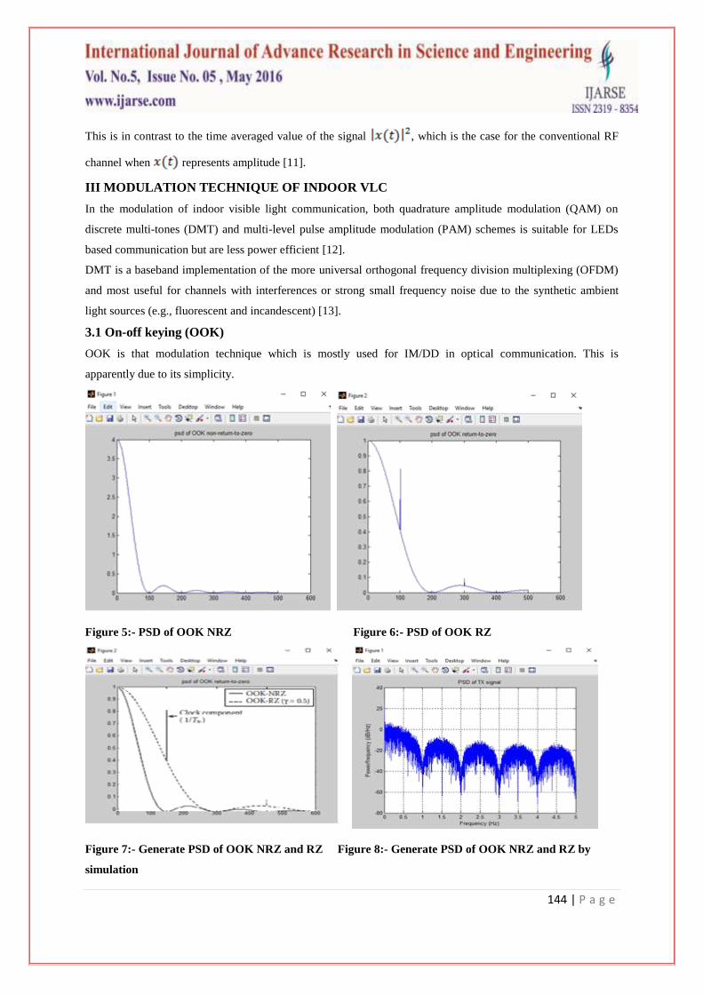
3.1 On-off keying (OOK)
OOK is that modulation technique which is mostly used for IM/DD in optical communication. This is
apparently due to its simplicity.
Figure 5:- PSD of OOK NRZ Figure 6:- PSD of OOK RZ
Figure 7:- Generate PSD of OOK NRZ and RZ Figure 8:- Generate PSD of OOK NRZ and RZ by
simulation
145 | P a g e
A bit one is simply represented by an optical pulse that occupies the entire or part of the bit duration while a bit
is zero is represented by the absence of an optical pulse.
Both the return-to-zero (RZ) and non-return-to-zero (NRZ) schemes can be applied. In the NRZ scheme, a pulse
with duration equal to the bit duration is transmitted to represent ‗1‘ while in the RZ scheme, the pulse occupies
only the partial duration of bit.
Where the average is power and is the bit duration [14].
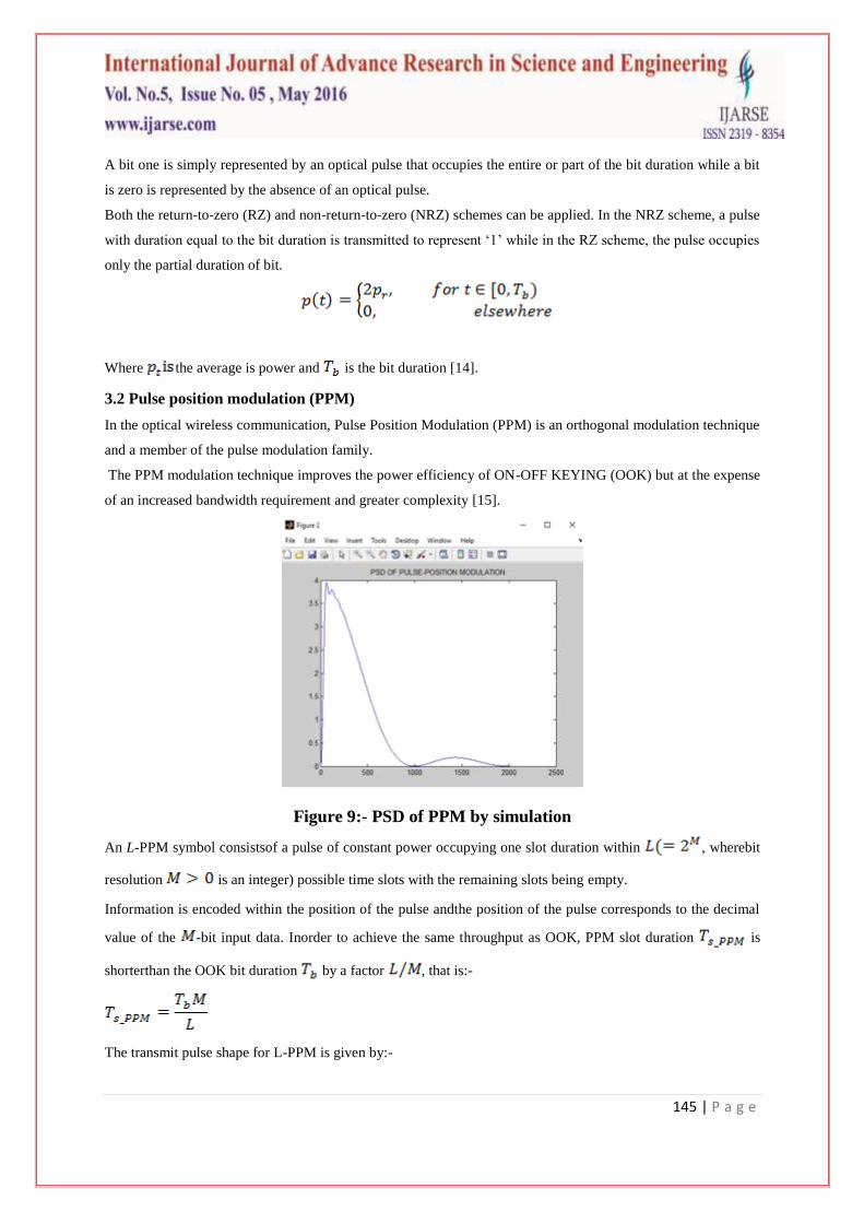
3.2 Pulse position modulation (PPM)
In the optical wireless communication, Pulse Position Modulation (PPM) is an orthogonal modulation technique
and a member of the pulse modulation family.
The PPM modulation technique improves the power efficiency of ON-OFF KEYING (OOK) but at the expense
of an increased bandwidth requirement and greater complexity [15].
Figure 9:- PSD of PPM by simulation
An L-PPM symbol consistsof a pulse of constant power occupying one slot duration within , wherebit
resolution is an integer) possible time slots with the remaining slots being empty.
Information is encoded within the position of the pulse andthe position of the pulse corresponds to the decimal
value of the -bit input data. Inorder to achieve the same throughput as OOK, PPM slot duration is
shorterthan the OOK bit duration by a factor , that is:-
The transmit pulse shape for L-PPM is given by:-
146 | P a g e
Where
Hence the PPM symbol sequences are given by:-
where is the PPM symbol sequence, is the pulse shaping function of unity
height and of duration is the symbol interval and is the peak optical power
of PPM symbol [16].
There are some criteria of an optical wireless communication channel of decreasing importance:-
3.3 Power efficiency
When evaluating the modulation technique suitable for indoor optical wireless communication systems is the
power efficiency.
Each modulation schemes offers a certain optical average power and therefore they are usually compared in
terms of the average optical power essential to succeed a desired BER performance or SNR
where is the energy per pulse and is the average energy per bit.
3.4 Bandwidth efficiency
The bandwidth efficiency is defined as:-
where is the achievable bit rate and is the bandwidth of the IR Tx-Rx.
IV OUTDOOR VISIBLE LIGHT COMMUNICATION
A VLC transceiver is an optical electronic device that converts visible light into an electrical signal and vice-
versa. The design of necessary devices for an outdoor application should take into account the particularities of
the application scenario, such as the significant presence of noise components. LEDs have come a long way
since their days has simple visual indicators. The advancements on LED technology during the last decade
increased the luminous output, reaching barriers that were once only seen by technologies such as high-intensity
discharge or ultra-high-performance lamps.
147 | P a g e
Furthermore, high energy efficiency and long lifetime assured LEDs a key role in the lighting market. They are
spread from such generic applications as indoor lighting, to more specific ones like vehicle illumination and
many others. In the area of general lighting, LEDs are gradually conquering the indoor consumers market, being
mostly limited by the initial cost barrier. However, in the street, lighting market, municipalities are strongly
embracing LEDs mostly driven by the segment reduction in electrical and maintenance costs, as well as political
incentives to ―green technologies‖. Other
applications, under which LEDs are becoming standard technology, include traffic control and warning light,
large outdoor information panels, vehicle front and back lights among others
The widespread usage, combined with the inherent ability of fast switching has made LEDs a natural vehicle to
the introduction of VLC as a complementary last mile access technology to the saturated RF spectrum.
Operating as a dual function lighting and information transmission unit, Each LEDs light spot can become part
of a communication networks as shown in figure 9.
In the particular field of ITS, LED-based traffic and vehicle lights provide support for data transmission of
application that can be related with dynamic traffic routing, public transportation scheduling, road safety and
many others.
Also, an access network supported by LED-based street lights and information panels can provide users with
access to location applications, local and internet access spread throughout an entire city.
V SYSTEM DESCRIPTION
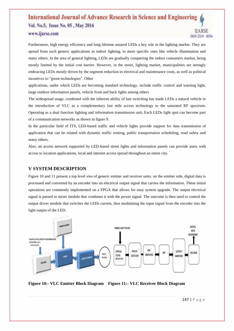
Figure 10 and 11 present a top level vies of generic emitter and receiver units. on the emitter side, digital data is
processed and converted by an encoder into an electrical output signal that carries the information. These initial
operations are commonly implemented on a FPGA that allows for easy system upgrade. The output electrical
signal is passed to mixer module that combines it with the power signal. The outcome is then used to control the
output driver module that switches the LEDs current, thus modulating the input signal from the encoder into the
light output of the LED.
Figure 10:- VLC Emitter Block Diagram Figure 11:- VLC Receiver Block Diagram
148 | P a g e
According to the desired communication range and the type of LEDs applied, an output lens can be applied to
shape output light beam.On the receiver side, the visible light pulses pass through an optical filter, before hitting
the photo-detector (PD). These results in small amplitude current which are then amplified and converted into
voltages using trans-impedance amplifier [18]. The resulting signal is then filtered, amplified and converted into
a digital format using an ADC. Synchronization, demodulation, frame processing and error detection/correction
can be adequately implemented using FPGA [19].
VI OUTDOOR OPTICAL CHANNEL
VLC systems in outdoor applications are preferably based on line of sight (LoS) configurations. The emitted
light from LED carries data information in wireless medium. Thus, the intensity of light of the emitter becomes
an important parameter, constraining transmission range. There are many external light noise sources such as
sun light, road street lights.
They deteriorate the transmitted signal and may cause false triggering of the receiver side. Both natural and
artificial ambient light induce shot noise on the photo detector side [20].
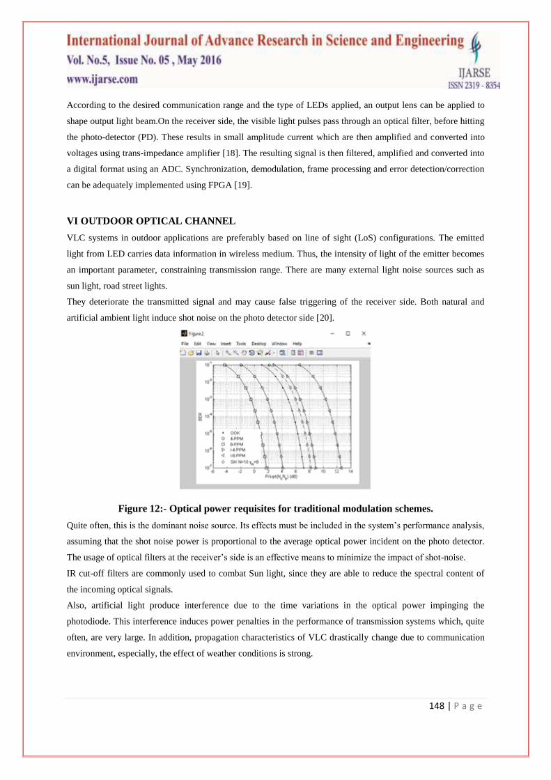
Figure 12:- Optical power requisites for traditional modulation schemes.
Quite often, this is the dominant noise source. Its effects must be included in the system‘s performance analysis,
assuming that the shot noise power is proportional to the average optical power incident on the photo detector.
The usage of optical filters at the receiver‘s side is an effective means to minimize the impact of shot-noise.
IR cut-off filters are commonly used to combat Sun light, since they are able to reduce the spectral content of
the incoming optical signals.
Also, artificial light produce interference due to the time variations in the optical power impinging the
photodiode. This interference induces power penalties in the performance of transmission systems which, quite
often, are very large. In addition, propagation characteristics of VLC drastically change due to communication
environment, especially, the effect of weather conditions is strong.
149 | P a g e
The received signal power fluctuates due to atmospheric obstacles such as rain or fog, in the propagation
channel limiting the communication range. Therefore in addition to the usage of filters, appropriate modulation
techniques must be deployed to enhance the performance of the VLC system in outdoor.
VII MODULATION TECHNIQUES
Modulation technique is one of the most important technical issues in the design of a communication system.
VLC systems for outdoor applications are subject to many external noise sources and therefore, robust
modulations techniques are especially required.
Bit error rate (BER)
The probability of error and SNR are two of the most important performance parameters of a communication
receiver.
This section presents the BER performance for several traditional modulation schemes used in IR
communication links.
These include, On-Off Keying (OOK), Pulse Position Modulation (PPM). Less traditional examples also
explored are, Inverse PPM (IIPPM – a special form of Multiple PPM) and Direct Sequence Spread Spectrum
(DSSS) [21].
The OOK transmitter emits a rectangular pulse of duration and intensity (peak power) to signify a one
bit, and no pulse to signify a zero bit. Assuming an additive white Gaussian noise (AWGN) channel, the BER is
given as:-
Where, is the average power and is the noise power spectral density.
Pulse position modulation (PPM)
PPM can offer higher average power efficiency making use of symbols with time slots (chips).
A constant power is transmitted during one of these chips and zero during remaining chips
therefore, encoding bits in the position of the high chip. For any greater than , PPM requires less
optical power than OOK.
In principle, the average optical power requirement can be made arbitrarily small by making suitably large, at
the expense of increased bandwidth. The BER is given as[21]:
150 | P a g e
Inverted- pulse position modulation (PPM)
IPPM is obtained inverting the pulse position of conventional PPM. The optical intensity is during the
sub-interval and everywhere else. Thus LED remains times as bright as conventional L-
PPM. The average power transmitted of I-L-PPM is . The BER is expressed as [22]:-
Sequence inverse keying (SIK)
DSSS SIK is able to minimize the effect of external noise sources. In this method, the incoming data is
multiplied by a spreading sequence. The transmitted signal consists of the spreading sequence itself, for binary
and its complement for binary . On the receiver, the detected signal is correlated with a version of the
spreading sequence, thus recovering the original data. In this case, the SNR is given by:-
Where and are the standard deviation and the optical power of the interfering signal, is the spreading
factor, and is the average optical power of the transmitted signal. Above equation shows that without
interfering sources, that is, under AWGN channel conditions, SIK and OOK have the same BER performance.
However, under the influence of interference the performance of DSSS-SIK increases [23].
VIII CONCLUSION
We have to analyse the indoor characteristics, channel modulation and modulation techniques for indoor VLC in
IM/DD by considering the visible light spectrum with respect to the single and multiple channels.
The entireestablished power from reflected paths and the RMS delay spread of the VLC cases are smaller than
those of the IR circumstances, which means the VLC has a larger optical transmission bandwidth. For multiple
optical sources, the channel bandwidth is imperfect in approximatelyatmospheres due to strong LOS modules.
This paper presented Visible Light Communication (VLC) systems for outdoor application. It is based on DSSS
and it is feasible to establish a low data rate communication link ranging up to using commercially
available LEDs. This communication range is adequate for data broadcast using LED based traffic signals. It is
also possible to explore similar system design concepts for data communication using public lighting system.
We have to analyse the outdoor VLC and modulation techniques that is (:- BER, PPM, IPPM, SIK). Also,
describe the emitter and receiver of outdoor VLC for communication link.
151 | P a g e
REFERENCES
[1]Z. Ghassemlooy and W. Popoola, optical wireless communication via system and channel modelling,
introduction of VLC systems.443-445
[2] J G Proakis, Digital Communications, New York: McGraw-Hill, 2004
[3] F R Gfeller and U Bapst, Wireless in-house data communication via diffuse infraredradiation, Proceedings
of the IEEE, 67, 1474–1486, 1979
[4] J M Kahn and J R Barry, Wireless infrared communications, Proceedings of IEEE, 85,265–298, 1997
[5] J B Carruthers and J M Kahn, Modelling of non-directed wireless Infrared channels,IEEE Transaction on
Communication, 45, 1260–1268, 1997
[6] T Komine, Visible Light Wireless Communications and Its Fundamental Study, Keio University, PhD thesis,
Japan, 2005
[7]J K Kim and E F Schubert, Transcending the replacement paradigm of solid-statelighting, Optics Express, 16,
21835–21842, 2008
[8] A M Street, P N Stavrinou, D C Obrien and D J Edwards, Indoor optical wireless systems—A review,
Optical and Quantum Electronics, 29, 349–378, 1997
[9] G W Marsh and J M Kahn, Channel reuse strategies for indoor infrared wireless communications, IEEE
Transactions on Communications, 45, 1280–1290, 1997
[10] S Hranilovic, On the design of bandwidth efficient signalling for indoor wireless optical channels,
International Journal of Communication Systems, 18, 205–228, 2005
[11] D A Rockwell and G S Mecherle, Optical wireless: Low-cost, broadband, optical access [Online]
Available: www freespace optic com/White Papers/optical wireless pdf
[12] T Lueftner, C Kroepl, M Huemer, J Hausner, R Hagelauer and R Weigel, Edgepositionmodulation for high-
speed wireless infrared communications, IEE ProceedingsOptoelectronics, 150, 427–437, 2003.
[13] K Sato and K Asatani, Speckle noise reduction in fiber optic analog video transmission using
semiconductor laser diodes, IEEE Transactions on Communications, 29, 1017–1024, 1981
[14] I D Association, Serial Infrared Physical Layer Specification, Version 1 4, 2001
[15] L W Couch, Digital and Analog Communication Systems, 6thed New Jersey: Prentice Hall, 2001
[16] A J C Moreira, R T Valadas and A M d O Duarte, Performance of infrared transmission systems under
ambient light interference, IEE Proceedings—Optoelectronics, 143, 339–346, 1996.
[17] Z. Ghassemlooy and W. Popoola, optical wireless communication via system and channel modelling,
introduction of VLC systems.443-445
[18] J G Proakis, Digital Communications, New York: McGraw-Hill, 2004
[19] F. R. Gfeller and U. Bapst, "Wireless in-house data communication via diffuse infrared radiation,"
Proceedings of theIEEE, vol. 67, pp. 1474-1486, 1979.
[20] I. L. Azevedo, M. G. Morgan, andF. Morgan, "The Transition to Solid-State Lighting," Proceedings of the
IEEE, vol. 97, pp. 481-510, 2009.
152 | P a g e
[21] A. J. C. Moreira, R. T. Valadas, and A. M. d. O. Duarte, "Optical interference produced by artificial light,"
Wirel. Netw.,vol. 3, pp. 131-140, 1997.
[22] N. Azzam, M. H. Aly, and A. K. AboulSeoud, "Bandwidth and power efficiency of various PPM schemes
for indoor wireless optical communications," in Radio Science Conference, 2009.NRSC 2009. National,
2009, pp. 1-11.
[23] K. K. Wong, T. O'Farrell, and M. Kiatweerasakul, "Infrared wireless communication using spectrum
techniques," Optoelectronics, IEE Proceeding vol. 147, pp. 308-314, 2000.