Embed Size (px)
Citation preview
Massachusetts Institute of Technology22.68J/2.64J
Superconducting Magnets
⇓
February 27, 2003
• Lecture #4 – Magnetic Forces and Stresses
1
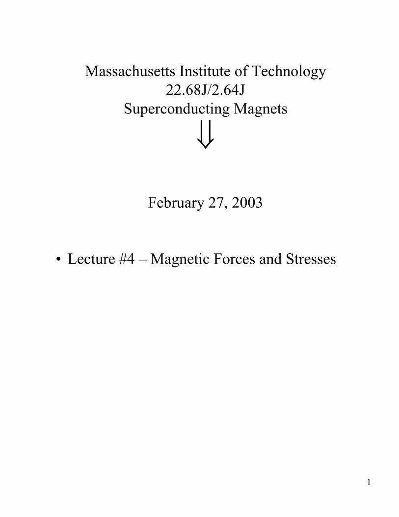
Forces•
E B2
= Vol 2µo
– Long, thin solenoid
equivalent to an internal pressure:
B
For a solenoid, energy stored in the magnetic field acts
– For B = 6 T ⇒ Internal pressure equivalent ≡ 140 atm – (typical working pressure of a gas cylinder)
– For B = 10 T ⇒ P = 400 atm, the yield stress of copper
Impact of Forces • Can break the structure and destroy the magnet. • Can damage insulation. • Can damage superconductor including overstraining
brittle Nb3Sn wire. • Can degrade magnet performance
– motion → release energy → instability → quench → training (?)
2
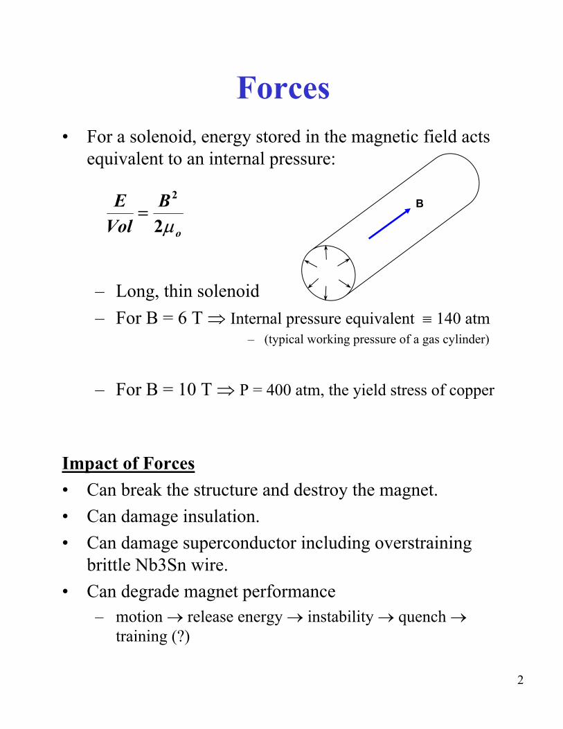
F = J × B
Compute the field throughout the winding volume
• Combine computation of forces and stress analysis with calculation of B
¾ Usually done by computer.¾ Simple analytical formulations are useful
for early stages of design. ¾ Must have knowledge of materials
properties: – Mechanical – Thermal (COE for thermal stresses)– From room temperature (RT) to 4K
3
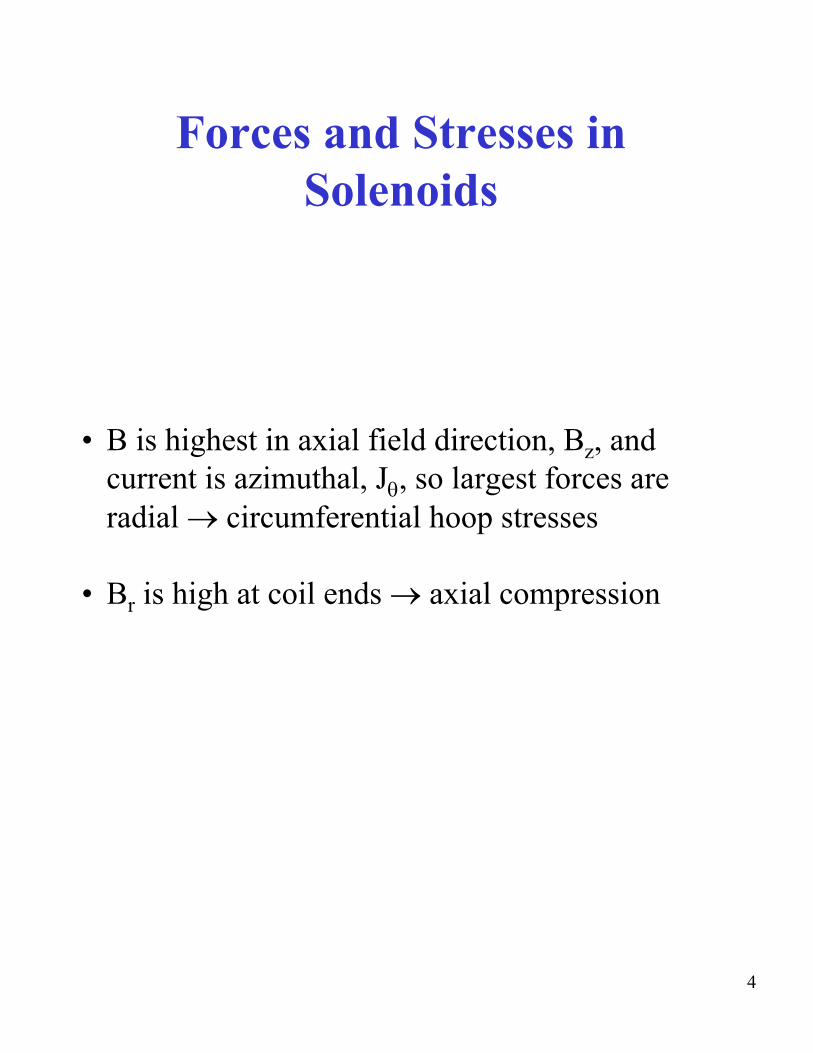
Forces and Stresses in Solenoids
• B is highest in axial field direction, Bz, and current is azimuthal, Jθ, so largest forces are radial → circumferential hoop stresses
• Br is high at coil ends → axial compression
4

Analysis
• Simplest assumption: Each turn acts independently
• The a tension develops in each turn:
T = B (r )Ir • Overall hoop stress σθ
σθ = r B )Jr [1](
Where both J and σθ are averaged over the winding pack
• Thus stresses increase with B, J and r (size)
5
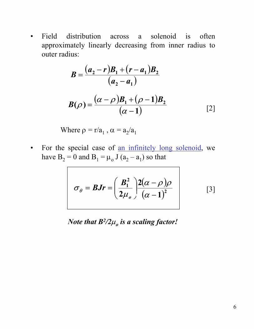
• Field distribution across a solenoid is often approximately linearly decreasing from inner radius to outer radius:
( a − r ) B + ( r − a ) B2 1 1 2B = ( a − a1 )2
B(ρ ) = (α − ρ) B + (ρ − 1) B1 2
[2](α − 1)
Where ρ = r/a1 , α = a2/a1
• For the special case of an infinitely long solenoid, we have B2 = 0 and B1 = µ o J (a2 – a1) so that
2 )σθ = BJr =⎛ B1 ⎞
⎟⎟ 2(α − ρρ
⎜⎜ 2 [3]⎝ 2µ o ⎠ (α − 1)
Note that B2/2µo is a scaling factor!
6
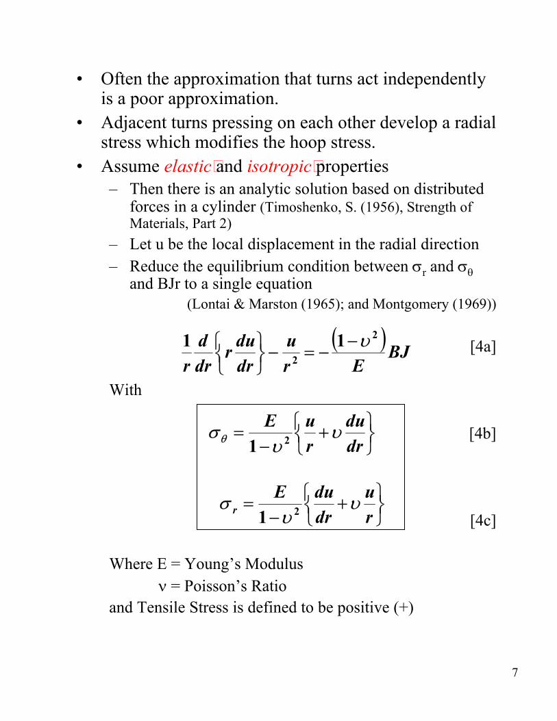
• Often the approximation that turns act independently is a poor approximation.
• Adjacent turns pressing on each other develop a radial stress which modifies the hoop stress.
• Assume elastic and isotropic properties – Then there is an analytic solution based on distributed
forces in a cylinder (Timoshenko, S. (1956), Strength of Materials, Part 2)
– Let u be the local displacement in the radial direction – Reduce the equilibrium condition between σ and σθr
and BJr to a single equation (Lontai & Marston (1965); and Montgomery (1969))
(−=
1 )2−υ1 d ⎧⎨⎩
rdudr
−⎫⎬⎭
u BJ [4a]2dr Er r
With
⎫⎬⎭
⎫⎬⎭
υ+
υ+
⎧⎨⎩
⎧⎨⎩
υ
υ
−
−
=
σ = θ
σ
E u du 1 2 r dr
E du u r 1 2 dr r
[4b]
[4c]
Where E = Young’s Modulus ν = Poisson’s Ratio
and Tensile Stress is defined to be positive (+)
7
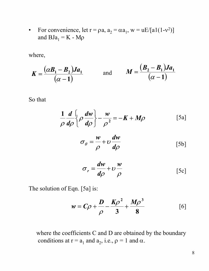
• For convenience, let r = ρ a, a2 = α a1, w = uE/[a1(1-ν 2)] and BJa1 = K - Mρ
where,
(α B − B2 ) Ja and M = ( B2 − B1 ) Ja11 1K = (α − 1) (α − 1)
So that
1 d ⎧ dw ⎫ ⎨ρ ⎬ −
w 2 = − K + Mρ [5a]
ρ dρ ⎩ dρ ⎭ ρ
σθ = w dw ρ+υ
dρ [5b]
σ = dw
+υ w
r dρ ρ [5c]
The solution of Eqn. [5a] is:
2 3D Kρ Mρ w = Cρ + − + [6]ρ 3 8
where the coefficients C and D are obtained by the boundary conditions at r = a1 and a2, i.e., ρ = 1 and α .
8

• Depending on coil design there may be radial stress at the inner and outer boundaries, e.g.:
– Inner winding mandrel – Outer pre-stress winding or structural support cylinder or ring.
• Most usual condition, though, is that the boundaries are free, i.e., σ = 0 at ρ =1 and α .r
• Substituting these conditions into [5c] and [6] allows definition of C and D and thus the stress functions:
2 )(⎨α 2 + + +
α − ρ ( 1 + 2 α υ + 1)⎫K ( 2 +υ)⎧
α 1 2 ⎬σθ = 3(α + 1) ⎩ ρ ( 2 +υ) ⎭
2M ( 3 +υ)⎧ 2 1 α ( 1 + 3υ) 2 ⎫ [7a]−− 8 ⎨α + +
ρ 2 ( 3 +υ) ρ ⎬ ⎩ ⎭
2
σ = K ( 2 +υ)⎧ 2 α 1 α ⎫
⎨α − + + 2 + − 1)ρ⎬r 3(α + 1) ⎩ ρ(α
⎭ 2M ( 3 +υ)⎧ 2 1 α 2 ⎫ [7b]
− ⎨α − + 2 − ρ ⎬8 ⎩ ρ ⎭
9
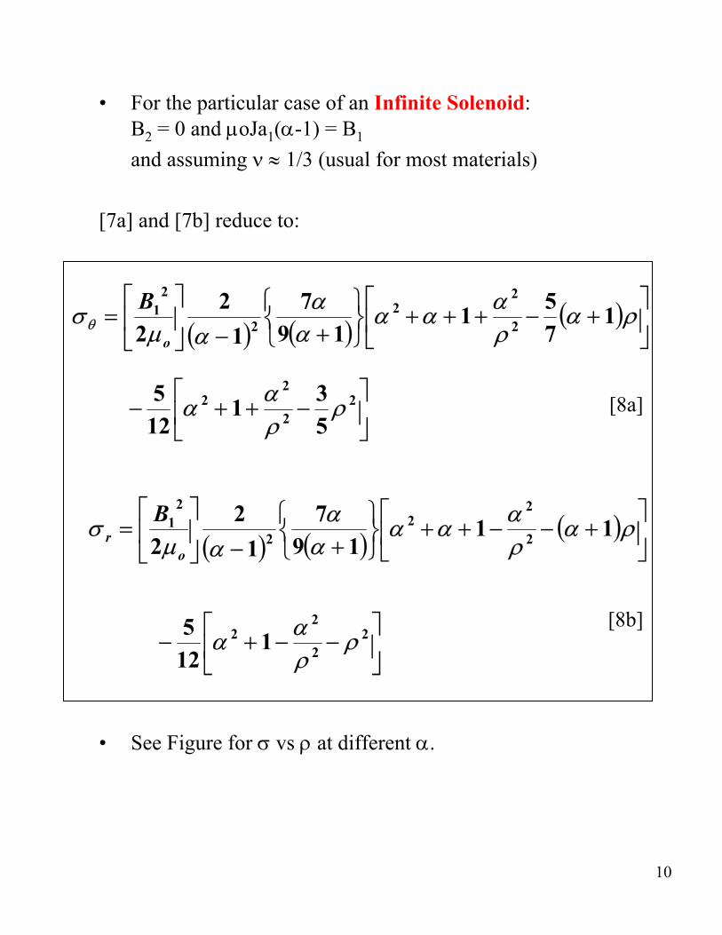
• For the particular case of an Infinite Solenoid: αB2 = 0 and µ oJa1( -1) = B1
and assuming ν ≈ 1/3 (usual for most materials)
[7a] and [7b] reduce to:
⎤ρ⎥⎦
⎤ ⎥⎦
ρ
)
)
+
+
α
α
(
(−
− αρ
αρ
α
2
α α
α
1
5
[8a]
αα
1B12 2
1 27 2 + + + 2 1
α
2 9 1 7
⎡ ⎢⎣
α o
⎤ ⎥⎦
⎡ ⎢⎣
⎫⎬⎭
⎫⎬⎭
⎤⎥⎦
)
ρ
)
25 2 ρ
+
−
3 2
+
+ +
(
αρ
− 2
(
512
⎧⎨⎩
αρ
⎧⎨⎩)
)
−
22 7 2
α
α
−
2B1
(
⎡⎢⎣
α
⎥⎦
(
α
⎤− + + 1
⎤⎥⎦
⎡⎢⎣
r 2 9 1 1 221µ o
−
µ
−
⎡⎢⎣
⎡⎢⎣
=
=
2 [8b]
σ
5 2
σθ
− + 221
12
• See Figure for σ vs ρ at different α .
10
• Comments
Thin Coil α = 1.3 – Large hoop stress for unsupported turn case – σr is effective in spreading out hoop stress and
lowering peak value.
Medium Coil α = 1.8 – Special case where σ θ = σ’ θ’ at ρ = 1, i.e., the peak hoop
stress is not affected by σr
Fat Coil α = 4 – Radial stress becomes tensile at inner layers. This
results in doubling the hoop stress at ρ = 1.
11

Conclusions
– Radial stress is beneficial in reducing hoop stress in solenoids if it is compressive.
– Radial stress makes matters worse if it is tensile.
– Also, tensile stress is bad for insulation – film and epoxy resins cannot take much tension before cracking or separating.
• Could cause winding delamination • Could lead to energy release and quenching.
– Often prestress is applied at RT during coil fabrication to maintain only radial compression under all conditions of cool-down and operating energization.
– Fig. 4.3 shows criteria derived by Middleton and Trowbridge to provide σr compression.
12

Other Considerations
• For thick windings, divide the coil into several thinner, mechanically separate, concentric sections to prevent radial tension.
• The assumption of isotropic properties (elastic) is often not good: – E for metals is usually much higher than E for
insulating materials. – This makes windings ‘spongy’ in the radial direction.
• Axial forces always cause compressive stresses and do not interact with σr and σθ . – Compute independently and sum them. – Insulating materials are often strong (or at least
adequate) in compression.
• A special case is a split pair solenoid which requires extra structure to bridge the gap.
13

Strains
• Mechanical and Thermal: σ 4 K θεθ =
σθ −υ r −δθEθθ r δθ = ∫ 300 Kα T dT
Er
σ 4 K rε = r −υ rθσθ −δ δ = ∫ 300 Kα dTr r r TE Eθr
υ rθ υθ r= • Condition of orthotropy: Eθ Edu r
ε r = dr
εθ = ur
• Consider forces and stress distribution under FAULT conditions, e.g. internal short in the coil – This can lead to substantial, and often unsupported
stresses and coil damage or destruction.
14
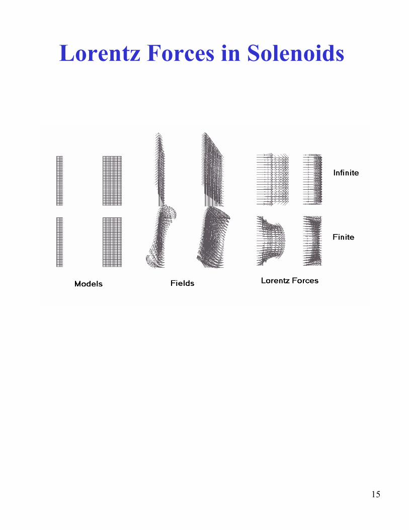
Lorentz Forces in Solenoids
15
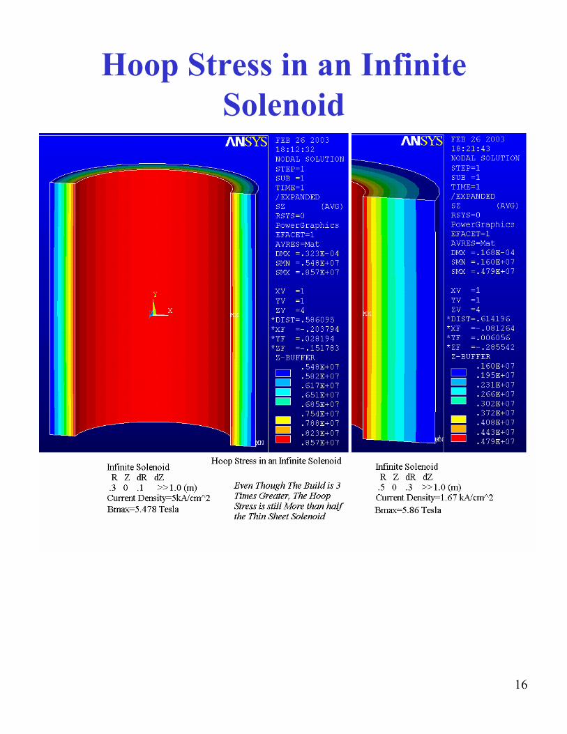
Hoop Stress in an Infinite Solenoid
16
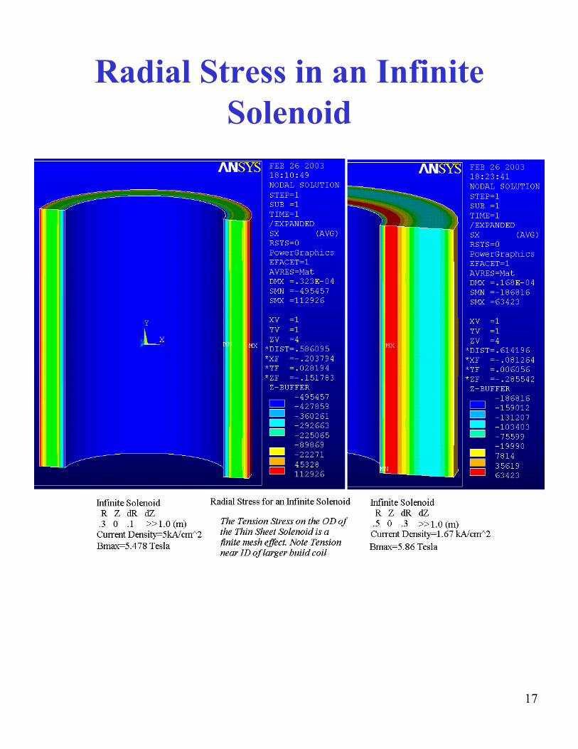
Radial Stress in an Infinite Solenoid
17
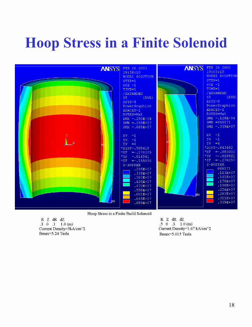
Hoop Stress in a Finite Solenoid
18

Radial Stress in a Finite Solenoid
19
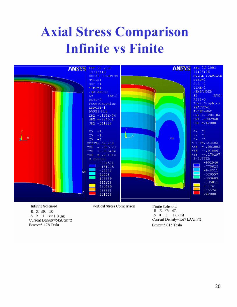
Axial Stress ComparisonInfinite vs Finite
20
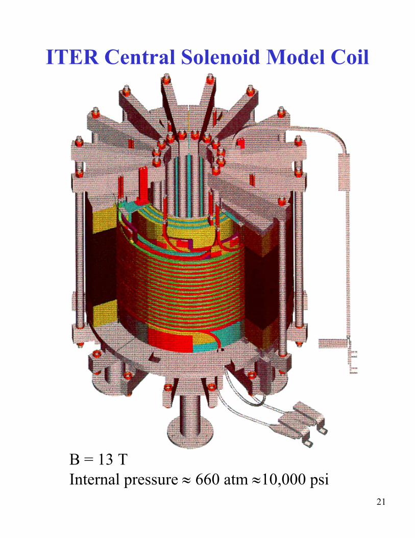
ITER Central Solenoid Model Coil
B = 13 T Internal pressure ≈ 660 atm ≈10,000 psi
21
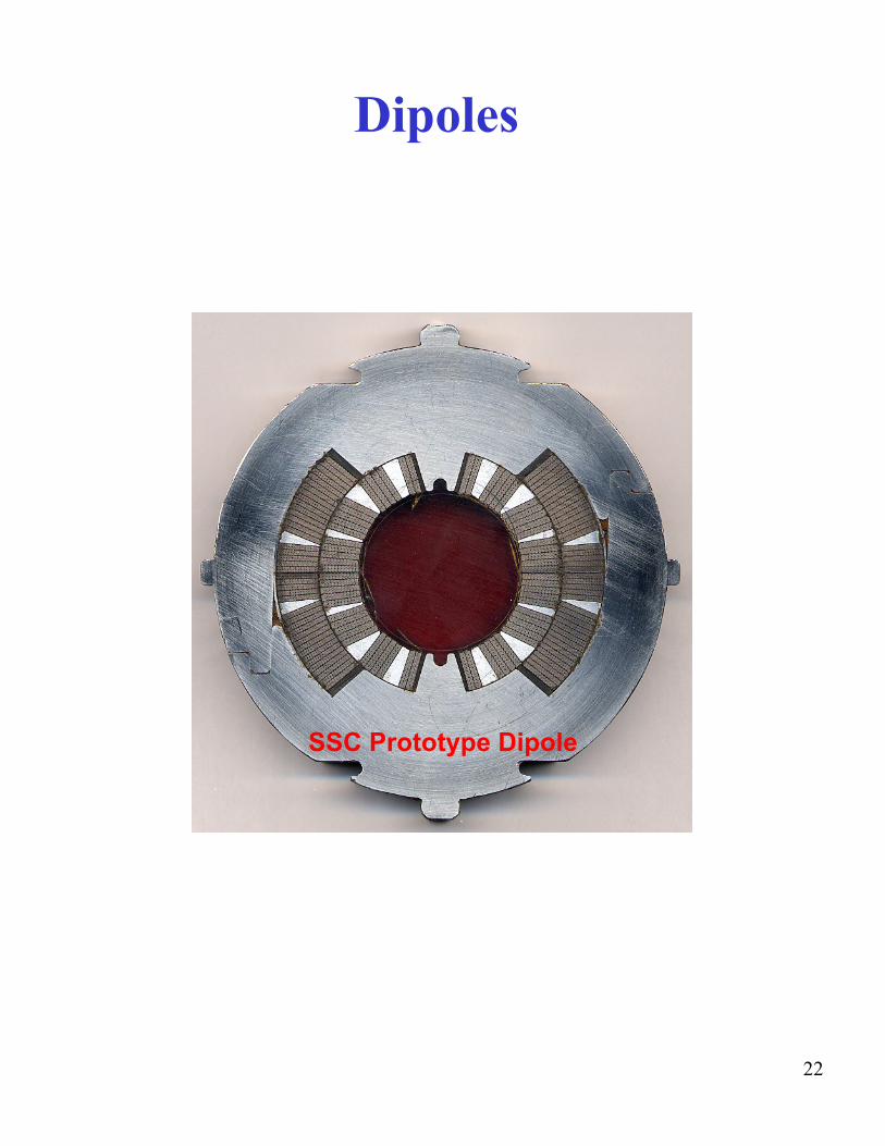
Dipoles
SSC Prototype Dipole
22
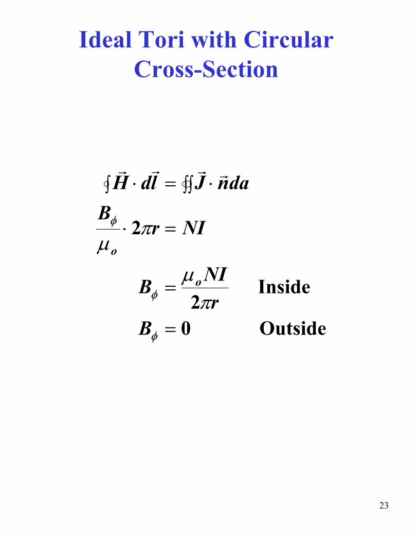
Ideal Tori with Circular Cross-Section
G∫ H ⋅ ld
G = ∫∫ J G ⋅ n Gda
B φ ⋅ 2πr = NI µo
B φ =µ NIo Inside2πr
B φ = 0 Outside
23
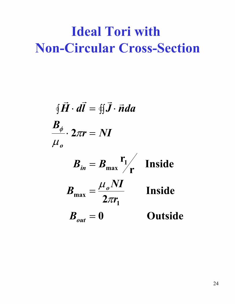
Ideal Tori withNon-Circular Cross-Section
G G G G⋅∫ ld H = ∫∫ J ⋅ da n Bφ ⋅ 2πr = NI µo
Bin = Bmax r1
r Inside
µ NIB = o Insidemax
B 2πr1
out = 0 Outside
24
PF Coils and Functions• OH Coils – Ohmic Heating
– Plasma initiation – Plasma heating by transformer action – High flux linkage with plasma current – No or low vertical field in plasma
• EF Coils – Equilibrium Field – Create vertical field at plasma for radial equilibrium
• Elongation Coils – Elongation of Plasma – Double or single null
• Shaping Coils – Shape plasma to D, bean or triangular shape in conjunction
with elongation coils • Control Coils
– Control plasma position both vertically and radially – Either inside Vacuum Vessel (VV) for fast control or outside
VV for slow control – Used in conjunction with other PF coil functions
• All coils are coaxial solenoids or Ring Coils • All coils excited independently with time-varying
currents (often bipolar) during plasma cycle – Fields from coils are superposed so current supply may
follow complex waveform for combining functions • Seldom use magnetic materials
– Exception: OH transformer, e.g. JET, Tore Supra (but not with SC magnets)
– Sometimes used for TF ripple correction 25
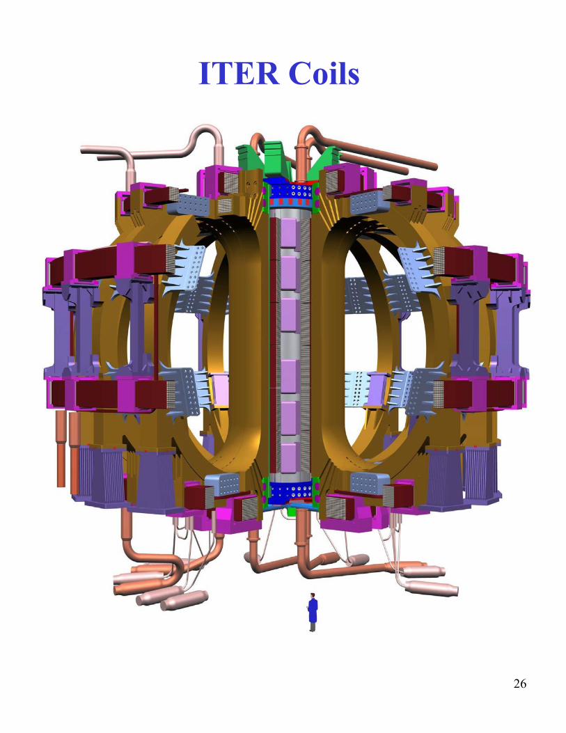
ITER Coils
26
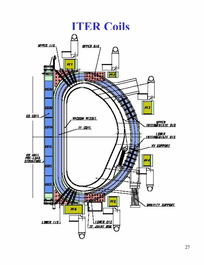
ITER Coils
27
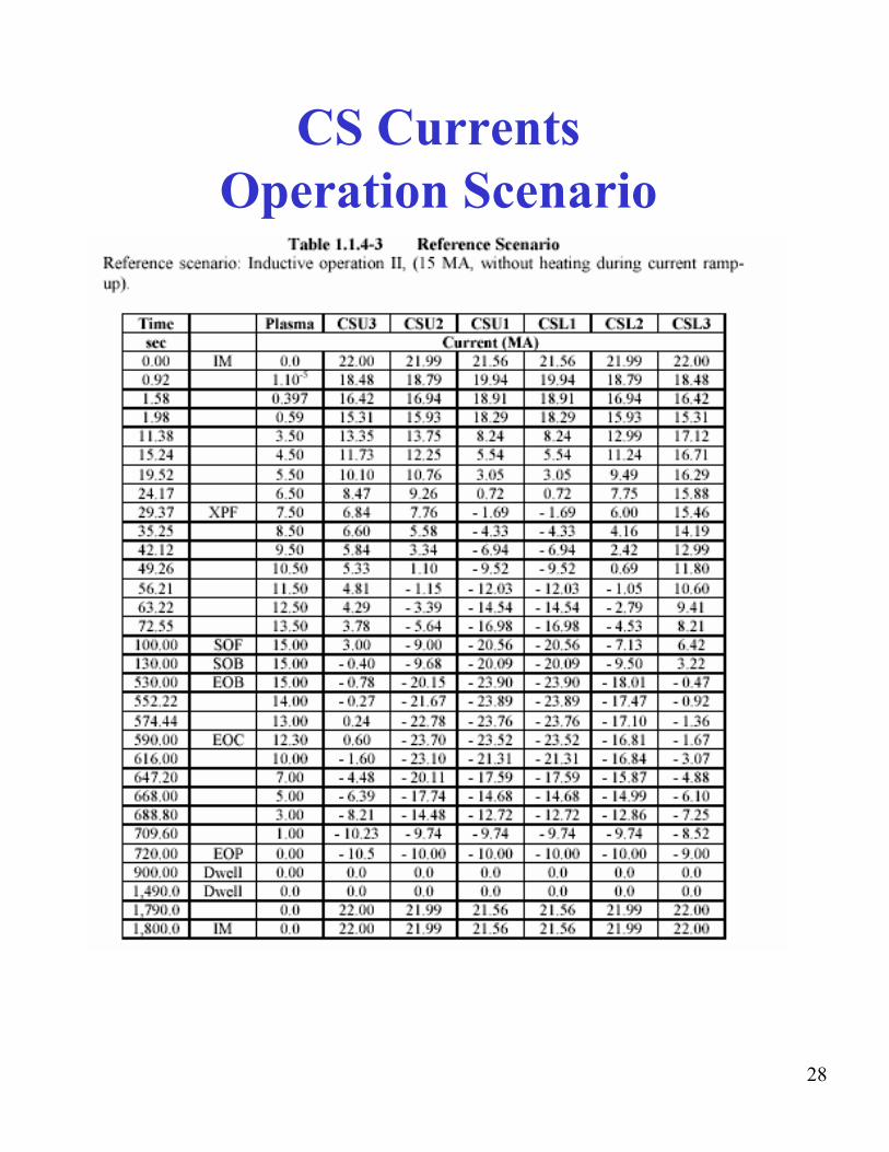
CS CurrentsOperation Scenario
28
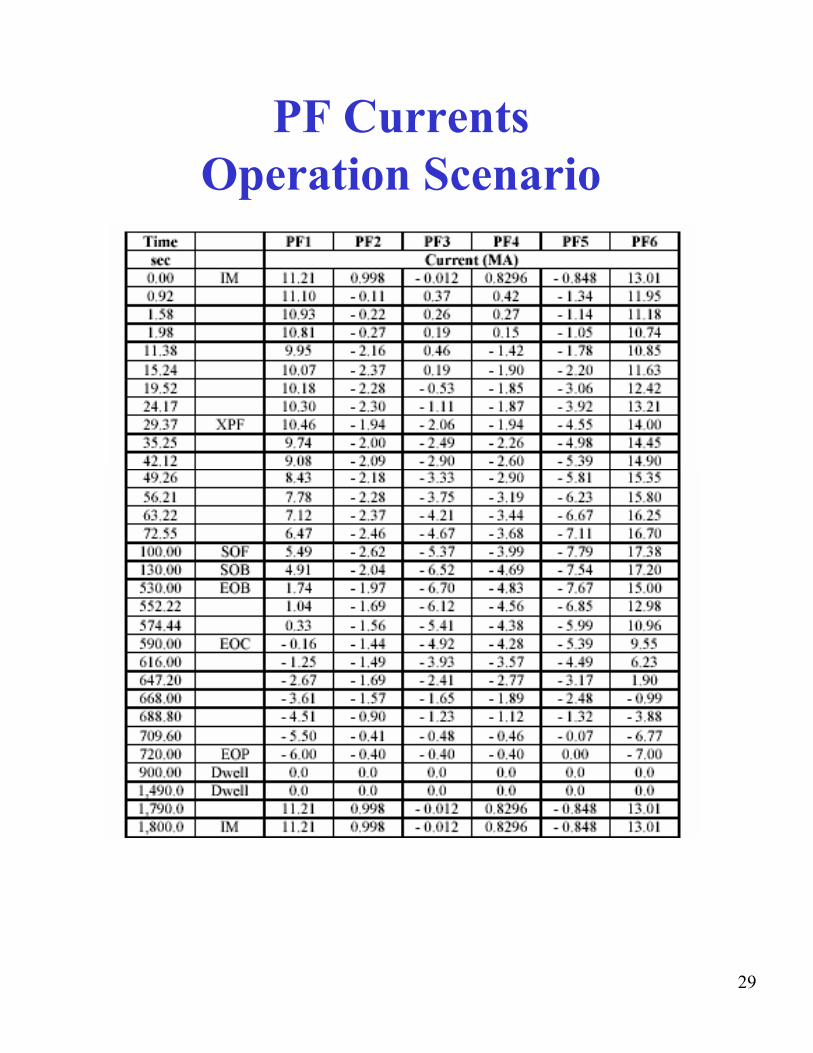
PF CurrentsOperation Scenario
29

CS and PF CurrentsOperation Scenario
0
10
20
30
0
-10
-5
0
5
10
15
20
0
i
ITER CS 15MA Senario
-30
-20
-10
500 1000 1500 2000
Plasma CSU3 CSU2 CSU1 CSL1 CSL2 CSL3
ITER PF 15MA Senario
500 1000 1500 2000
Ser es1 PF1 PF2 PF3 PF4 PF5 PF6
30

Out-Of-Plane (OOP) Forces in TF Coils
• Under usual operating conditions there are no out-of-plane loads on a TF coil due to other TF coils
• Watch out for fault conditions (e.g. unequal currents)
31
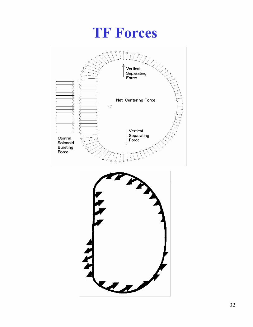
Figure 3
TF Forces
32
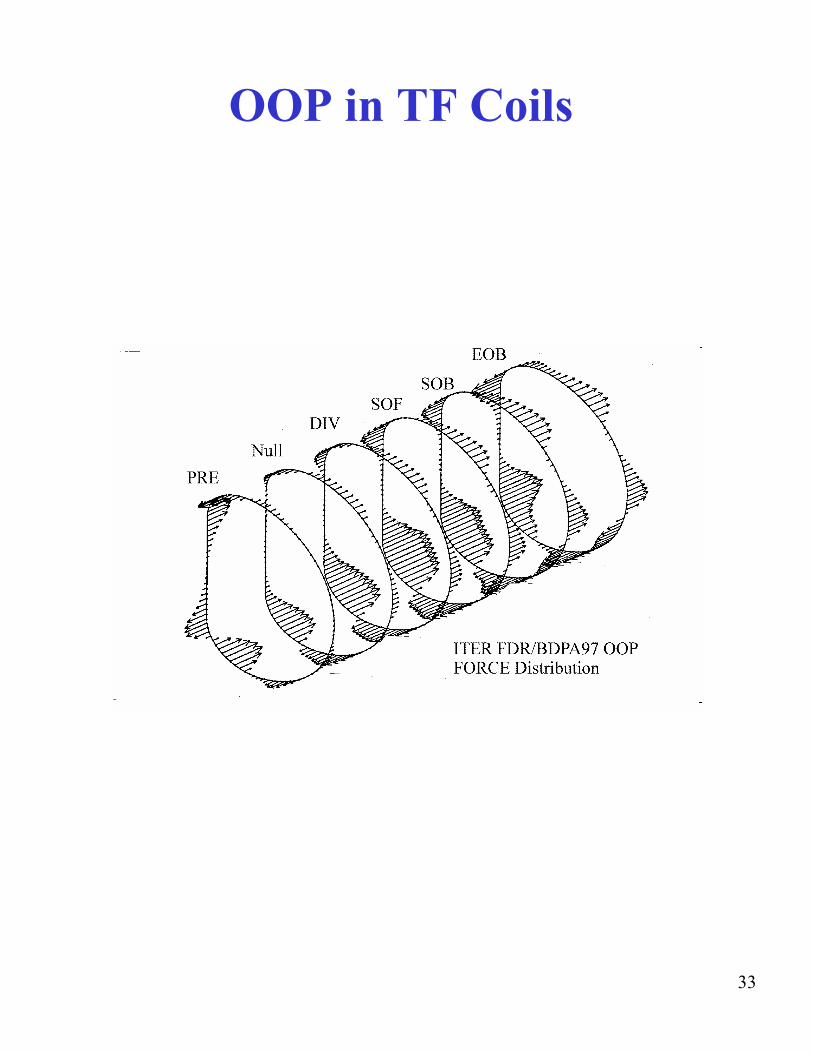
OOP in TF Coils
33

Force Calculation
= 21 (I× ds B
1
)dF
NI 2 ⎞⎟⎠
γγ
⎛⎜⎝
+Fz o 4π
=
µ
ρ=γ
=1−
radius minor where r radius major av
γ: Note 1<
⎡ ⎤µ NI 2 o 1Fr −⎢
⎢⎣ 1 ⎥
⎥⎦ = ( )1 2
⎯→⎯
γ2 −
: Note Since γ 1 Fr < Force) (Centering 0<
34
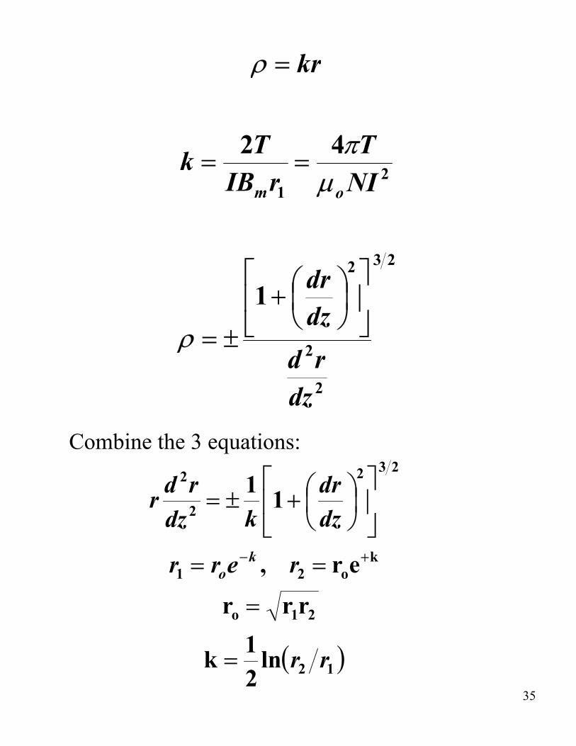
ρ = kr
2 T 4 π Tk = = IBmr1 µ NI 2
o
⎡ ⎛ dr ⎞ 2 ⎤
2 3
⎢ 1 + ⎜ ⎟ ⎥ ρ ± = ⎣ ⎝
2
dz ⎠ ⎦ r d
dz2
Combine the 3 equations: 2r d 1 ⎡ ⎛ dr ⎞
2 ⎤ 2 3
r ± = ⎢ 1 + ⎜ ⎟ ⎥dz2 k ⎣ ⎝ dz ⎠ ⎦ − k + k= e r , = e rr1 o r2 o
( ) 12
21o
ln2 1k
r
rr=
= r r
35
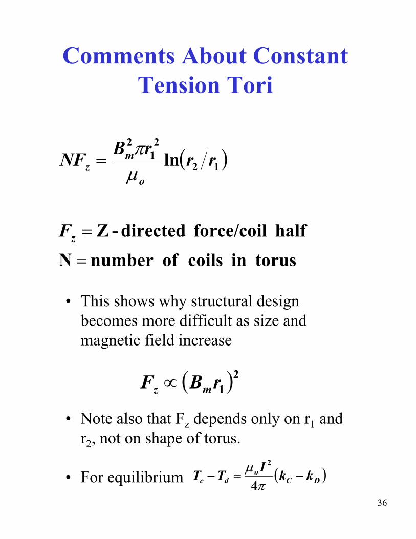
Comments About Constant Tension Tori
2 2
NFz = Bmπr1 ln(r2 r )1µo
F = -Z half force/coil directedz
N= torus in coils of number
• This shows why structural design becomes more difficult as size and magnetic field increase
2F ∝ (Bmr1 )z
• Note also that Fz depends only on r1 and r2, not on shape of torus.
o• For equilibrium T − Td =µ I 2
(k − kD )c 4π C
36
Comments About Constant Tension Tori
• Methods of connection and supports affect constant T characteristics and generate bending moments.
• Each coil segment is constant T, but not momentless unless coil reactions respond to loads in a particular way: – Must account for shape change in response to
EM loads + reactions. – Must take account of actual coil and structure
stiffness and cross-sections. – Must account for discreteness of coils in
toroidal direction. – Actual location and size of coil supports is
affected by overall Tokamak design: • Size, location of plasma, VV, shields, ports,
maintenance access, etc. – In general, a 3D analysis of loads and stresses
must be made.
37
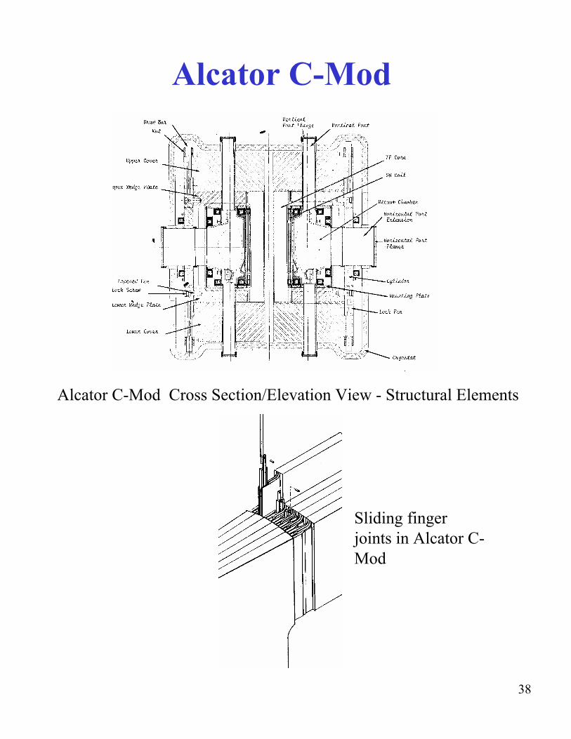
Alcator C-Mod
Alcator C-Mod Cross Section/Elevation View - Structural Elements
Sliding finger joints in Alcator C-Mod
38
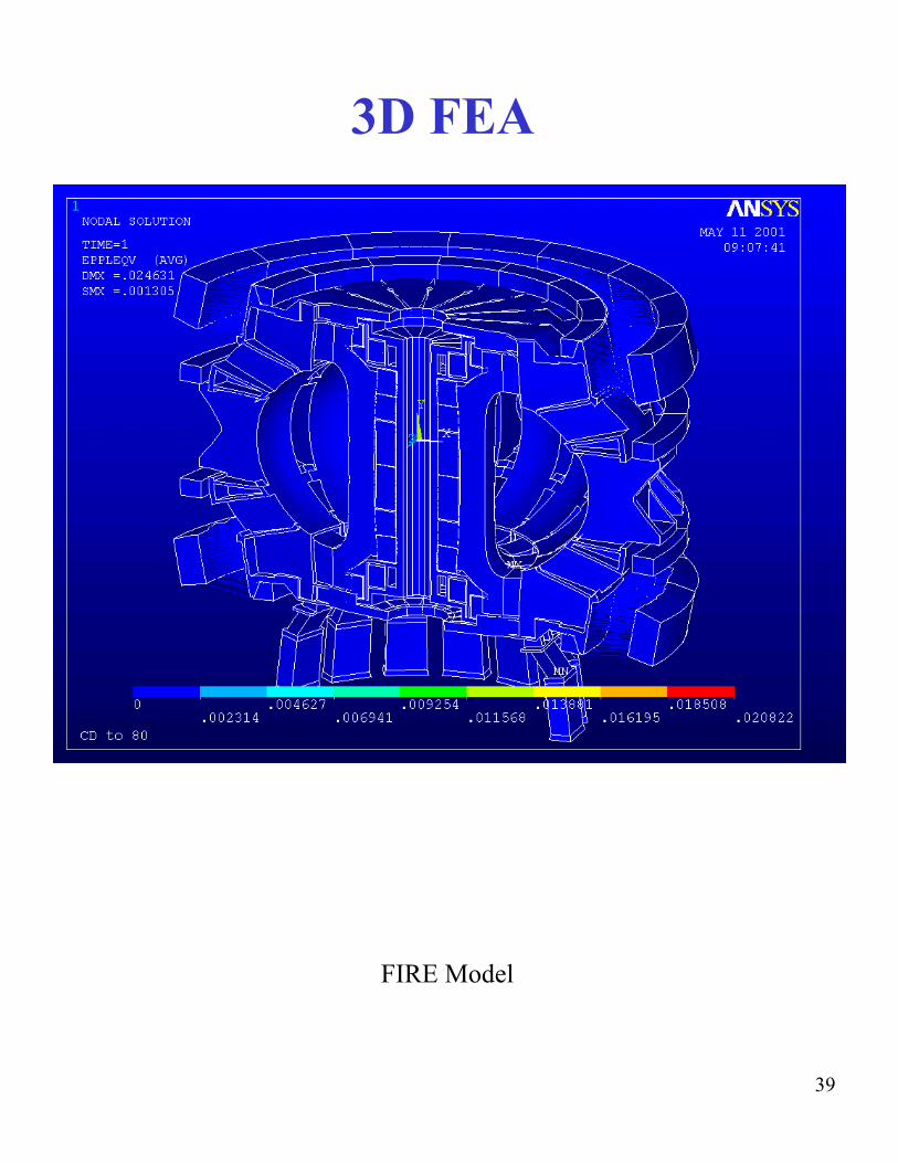
3D FEA
FIRE Model
39