Embed Size (px)
Citation preview
DUNCAN BOURKEAssociate, P.Eng
Mass Timber Connections: Building Structural Design Skills
DISCLAIMER: THIS PRESENTATION WAS DEVELOPED BY A THIRD PARTY AND IS NOT FUNDED BY WOODWORKS OR THE
SOFTWOOD LUMBER BOARD.

“The Wood Products Council”is a Registered Provider with The American Institute of Architects Continuing Education Systems (AIA/CES), Provider #G516.
Credit(s) earned on completion of this course will be reported to AIA CES for AIA members. Certificates of Completion for both AIA members and non-AIA members are available upon request.
This course is registered with AIA CES for continuing professional education. As such, it does not include content that may be deemed or construed to be an approval or endorsement by the AIA of any material of construction or any method or manner of handling, using, distributing, or dealing in any material or product.__________________________________
Questions related to specific materials, methods, and services will be addressed at the conclusion of this presentation.

For engineers new to mass timber design, connections can pose a particular challenge. This course focuses on connection design principles and analysis techniques unique to mass timber products such as cross-laminated timber, glued-laminated timber and nail-laminated timber. The session will focus on design options for connection solutions ranging from commodity fasteners, pre-engineered wood products and custom-designed connections. Discussion will also include a review of timber mechanics and load transfer, as well as considerations such as tolerances, fabrication, durability, fire and shrinkage that are relevant to structural design.
Description

While the presenters have tried to be as accurate as possible, they cannot be held responsible for the designs of others that might be based on the material presented in this workshop. The material covered in this workshop is intended for the use of professional personnel who are competent to evaluate the significance and limitations of its content and recommendations and who will accept the responsibility for its application. The presenters and the sponsoring organizations disclaim any and all responsibility for the applications of the stated principles & values and for the accuracy of any of the material presented in the workshop.
Disclaimer
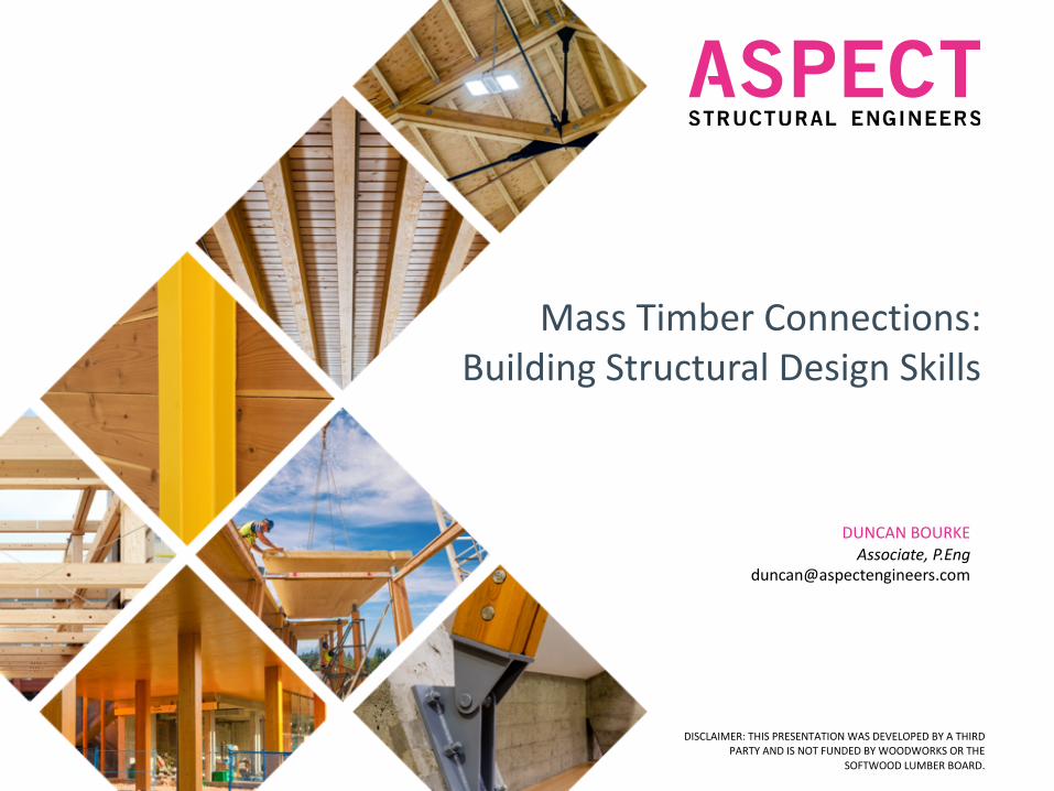
1. Review the timber mechanics that are relevant to mass timber design including, grain orientation and dimensional stability and define how loads are transferred in timber connections.
2. Consider practical aspects of design that are not traditionally in the scope of a structural design for other materials but may be relevant for mass timber such as tolerances, fabrication, durability, fire, and shrinkage.
3. Explore connection solutions available including commodity fasteners, pre-engineered products and custom designed connections.
4. Learn about cutting edge connection technologies and resources for learning more.
Learning Objectives

Introduction
1. Mass Timber Maturity
2. Basics of Connection Design
3. Practical Considerations
4. Design Solutions
5. Next Generation of Connections
Agenda

• Appreciate the difference between Behavior and Strength
• Small Ø are better than large (t/d=5)
• NEVER use traditional lag screws again
3 Things to remember

Introduction

Our Office Locations
VANCOUVER, CANADA INTERLAKEN,
SWITZERLANDTORONTO,CANADA

Our Projects

What We Do

“Engineers are good at solving problems.
The trick is to make sure to solve the right problems and not the first one that is encountered along the way”
How We Think

1.0 Mass Timber Maturity

Where We Are At

2.0 Basics of Connection Design

Connection Design Depends On:
• Nature of the forces and their magnitude
• Practicality
• Production
• Geometry
• Environmental conditions
• Aesthetics
• Cost
• Fire performance

2.1 Environment
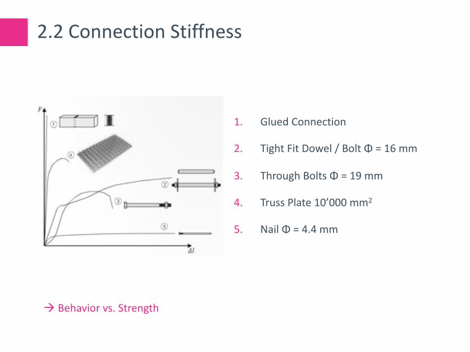
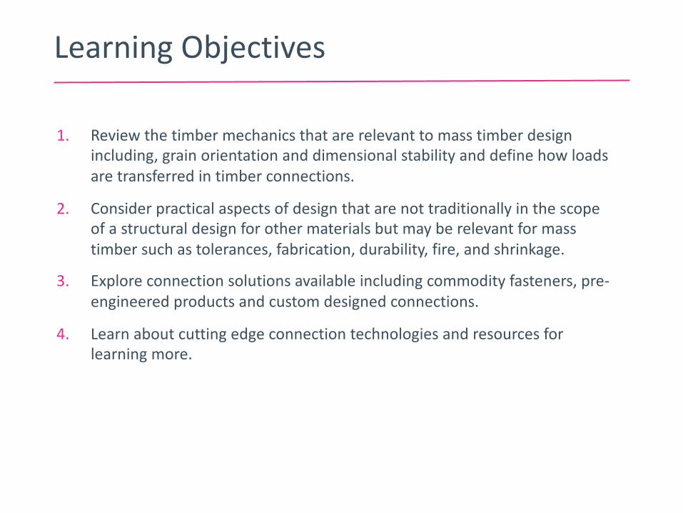
2.2 Connection Stiffness
1. Glued Connection
2. Tight Fit Dowel / Bolt Φ = 16 mm
3. Through Bolts Φ = 19 mm
4. Truss Plate 10’000 mm2
5. Nail Φ = 4.4 mm
à Behavior vs. Strength

2.3 Bolt vs. Tight Fit Dowels
Tight Fit BoltThrough Bolt

2.3 Bolt vs. Tight Fit Dowels
Tight Fit Dowel with Plug
Tight Fit Dowel flush
Tight Fit Dowel with projection
Through Bolt
Tight Fit Bolt

2.3 Bolt vs. Tight Fit Dowels
Size of hole in Wood Size of hole in Steel Use of ConnectionTight Fit Dowel/Bolt
Same size as pin/bolt diameter
Up to 1/32” larger than pin/bolt diameter
Typically used for engineered connections without additional load transfers (i.e. w/o bearing plates for example).
Through Bolt
Up to 1/16” larger than bolt diameter
Up to 1/16” larger than pin/bolt diameter
Typically used in connections where the bolt serves as a positioning aid.
Traditional heavy timber buildings may also feature such a connection.
This type of connection should be avoided in heavily loaded connections or if part of the SFRS.

2.3 Bolt vs. Tight Fit Dowels
* NDS HAS 75% CAP FOR DRIFT PINS…

2.3 Bolt vs. Tight Fit Dowels
Fu = Ultimate Strength Fy = Yield Strength

2.4 Bolts / Dowels - Slenderness
λ = td
Where;
t = member thickness
d = dowel or bolt diameter
à Behavior vs. Strength

2.5 Bolts / Dowels – Failure Mode
NOTE: THESE MODES DO NOT CORRESPOND TO THE NDS. THEY ARE BASED ON THE RESEARCH PAPERS QUOTED

2.5 Bolts / Dowels – Failure Mode
NOTE: THESE MODES DO NOT CORRESPOND TO THE NDS. THEY ARE BASED ON THE RESEAERCH PAPERS QUOTED

2.6 Bolts / Dowels – Seismic Design
NOTE: THESE MODES DO NOT CORRESPOND TO THE NDS. THEY ARE BASED ON THE RESEAERCH PAPERS QUOTED

2.7 Bolts / Dowels - Modus 3?
• The slenderness limit λy,1 in order to achieve Mode 2 is described as:
• λy,1 = 2 ∗ Mufh∗d 3
• Or a minimum wood thickness for a given fastener per:
• ty,1 = 2 ∗ Mufh∗d
• The slenderness limit λy,2 in order to achieve Mode 3 is described as:
• λy,2 = 4 ∗ Mufh∗d 3
• Similarly, this can be represented as a minimum wood thickness for a given fastener per:
• ty,2 = 4 ∗ Mufh∗d
• Where;
• Mu = Plastic bending resistance of the dowel/bolt in
[N-mm]
fh = Characteristic embedment strength [N/mm2]
d = Dowel/bolt diameter in [mm]
• Mu = 0.26 * fu * d 2.7 [N-mm]
fh,0,k = 0.082 (1- 0.01 d) ρk [N/mm2
fh,90,k = fh,0,k / (1.35 + 0.015 d) [N/mm2]
fh,α,k = Embedment strength at any angle to grain;
interpolate between fh,0,k and fh,90,k in [N/mm2
ρk = Characteristic density of wood in [kg/m3]
• For design purposes, ty,1 should be considered the minimum member thickness used (Mode 2), where ty,2 should be considered the ideal thickness (Mode 3).
• For connections with multiple knife plates, the minimum member thickness should be taken based on Mode 3.
Reference: Load-carrying behaviour of steel-to-timber dowel connections; Adrian Mischler, Helmut Prion, Frank Lam; https://pdfs.semanticscholar.org/bd4b/a80168b8d48ab053ca29960ddb4842136041.pdf
NOTE: THESE MODES DO NOT CORRESPOND TO THE NDS. THEY ARE BASED ON THE RESEAERCH PAPERS QUOTED

2.7 Bolts / Dowels - Modus 3?
In order to obtain the characteristic density, the mean oven-dry relative density can be multiplied with a factor of approximately 0.84.
Species Mean Oven-Dry Relative Density(i.e. oven dry specific gravity)
Characteristic Density at 12%MC(i.e. 5th percentile)
D.Fir-Larch (sawn lumber and Glulam) 0.49 410 Kg/m3
Hem-Fir (sawn lumber and Glulam) 0.46 385 Kg/m3
Spruce-Pine-Fir (sawn Lumber) 0.42 350 Kg/m3
Spruce-Pine (Glulam) 0.44 370 Kg/m3
Northern Species 0.35 300 Kg/m3
Black Spruce (Glulam) 0.56 470 Kg/m3
Parallam (PSL) 0.50 420 Kg/m3
Laminated Strand Lumber (LSL) 0.50 420 Kg/m3
Laminated Veneer Lumber (LVL) 0.50 420 Kg/m3

2.7 Bolts / Dowels - Modus 3?
à Behavior vs. Strength
NOTE: THESE MODES DO NOT CORRESPOND TO THE NDS. THEY ARE BASED ON THE RESEAERCH PAPERS QUOTED
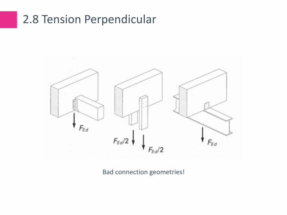
2.8 Tension Perpendicular
Bad connection geometries!

2.8 Tension Perpendicular
Upper portion is 8! times stiffer
But both portions need to deflect the same amount

2.8 Tension Perpendicular

2.8 Tension Perpendicular
In general, if a/h ≥ 0.7, the effect of tension perpendicular can be ignored. This should be the preferred approach to any connection

2.9 Movement
Be realistic about actual fluctuation of EMC
It takes quite a while for larger cross sections to equalize throughout the cross section
shrinkage
swel l ing

2.9 Movement

2.10 Summary
• Direct load path
• Respect Wood Movement (and design for it!)
• Bolts / Dowels to have ductile failure modes
• Careful with tension perpendicular
• Avoid horizontal wood in the vertical load path
• Old school bearing type connections often economical
• Design with fabrication and installation in mind à next chapter

3.0 Practical Considerations

3.1 Equipment
• Hand Tools

3.1 Equipment
• CNC

3.2 Installers

3.3 Overview
Practical Considerations for Connection Designs
Origin of Issue Where to address the Issue
Des
ign
Fabr
icat
ion
Tran
spor
tatio
n
Inst
alla
tion
Use
Des
ign
Fabr
icat
ion
Tran
spor
tatio
n
Inst
alla
tion
Use
Supply Capabilities
CNC machining vs Hand-framing of wood members x x
Supply Capabilities
Welding / machining of custom steel pieces x x x
Shrinkage Movement (or restricted movement) of wood due to fluctuation of moisture content
x x
Tolerances Missing tolerance level in standards x x x
Tolerances Member size not as per specs, assembly of members doesn’t fit x x x x
Tolerances Interface to other materials (steel and concrete) doesn’t fit. Steel and concrete have much larger tolerances
x x x x
Fire Resistance Charring of wood, reduction of cross section, heat transfer x x x x
Fire Resistance Exposed connectors x x x x

3.3 Overview
Practical Considerations for Connection Designs
Origin of Issue Where to address the Issue
Des
ign
Fabr
icat
ion
Tran
spor
tatio
n
Inst
alla
tion
Use
Des
ign
Fabr
icat
ion
Tran
spor
tatio
n
Inst
alla
tion
Use
Local Workforce
Installation strategy needs to respect labor skill sets available. x x
Site Conditions Crane type and locations may impact member length and require add'lsplices.
x x x
Speed of installation
Maximize site production, limited crane time available x x
Speed of installation
Connection types x x x
AHJ AHJ is not familiar with the type of construction x x
AHJ AHJ does not facilitate the use of alternate connectors x x
Drift Compatibility
Connections need to accommodate lateral movement x x x x
Detail Complexity
Multiple members framing coming together x x

4.0 Design Solutions

4.1 Commodity (NDS Dowel-Type)
4.1.1 Standard Hex Bolts
Applications Pros Cons• Direct beam to beam connections
(in shear)• Beam to beam or beam to column
connections via knife or side plates• Nominal connectors for plate
saddles/bearing connections
• Readily Available• Skilled trades not required for
installation• Can keep bolt heads exposed for
architecturally expressive exposed old-school heavy timber connections
• Can be used for timber connection to any material (concrete, steel, masonry)
• Connections are naturally exposed• Both sides of connection must be
accessible • Bolt head/nut and washer must be
perpendicular to connected surfaces (or shimmed or notched/recessed to suit)

4.1 Commodity (NDS Dowel-Type)
4.1.1 Standard Hex Bolts

4.1 Commodity (NDS Dowel-Type)
4.1.2 Standard Hex Lag Screws
Applications Pros Cons• Direct beam to beam connections
(in shear)• Beam to beam or beam to column
connections via side plates• Nominal connectors for plate
saddles/bearing connections where only one side is accessible
• Readily Available• Can keep bolt heads exposed for
architecturally expressive old-school exposed heavy timber connections
• Only one side of connection needs to be accessible
• May be loaded in tension/withdrawal (but please avoid it)
• Very time consuming to install (skill needed)
• Connections are naturally exposed• Lag screw head must be
perpendicular to side member surface

4.1 Commodity (NDS Dowel-Type)
4.1.3 Standard Wood Screws
Applications Pros Cons• Light wood frame connections (side
members <1 ½”)• Loading permitted in shear and
tension/withdrawal
• Readily Available• Relatively quick to install with a
power drill• Skilled trades not required• Variable head sizes and shapes –
can be flush or recessed if required• Small heads = low connection
visibility• May be installed at an angle to the
surface (with reduction factor) • Only one side of connection needs
to be exposed• Predrilling not required
• Design diameter varies. Important to clearly specify screws.
• Relatively short standard lengths available
• Small resistances

4.1 Commodity (NDS Dowel-Type)
4.1.4 General – Failure Modes
Credit: AWC/NDS

4.1 Commodity (NDS Dowel-Type)
4.1.4 General – Failure Modes
Credit: AWC/NDS

4.1 Commodity (NDS Dowel-Type)
4.1.4 General – 6-3/4” D.Fir-L Glulam
Reference: http://www.awc.org/codes-standards/calculators-software/connectioncalc

4.1 Commodity (NDS Dowel-Type)
4.1.4 General – 6-3/4” D.Fir-L Glulam
Based on 4d spacings as per NDS:
5/8” = 1 fastener every 2.5” = 2650lbs/inch
1” = 1 fastener every 4” = 2936lbs/inch
1” bolt only 10% better but brittle failure mode
à Behavior vs. Strength

4.2 Pre-Engineered / Proprietary
Lag Screws Self Tapping Screw
4.2.1 Screws

4.2 Pre-Engineered / Proprietary
4.2.1 Screws

4.2 Pre-Engineered / Proprietary
4.2.1 Screws

4.2 Pre-Engineered / Proprietary
4.2.1 Screws
Credit: MyTiCon
4.2 Pre-Engineered / Proprietary
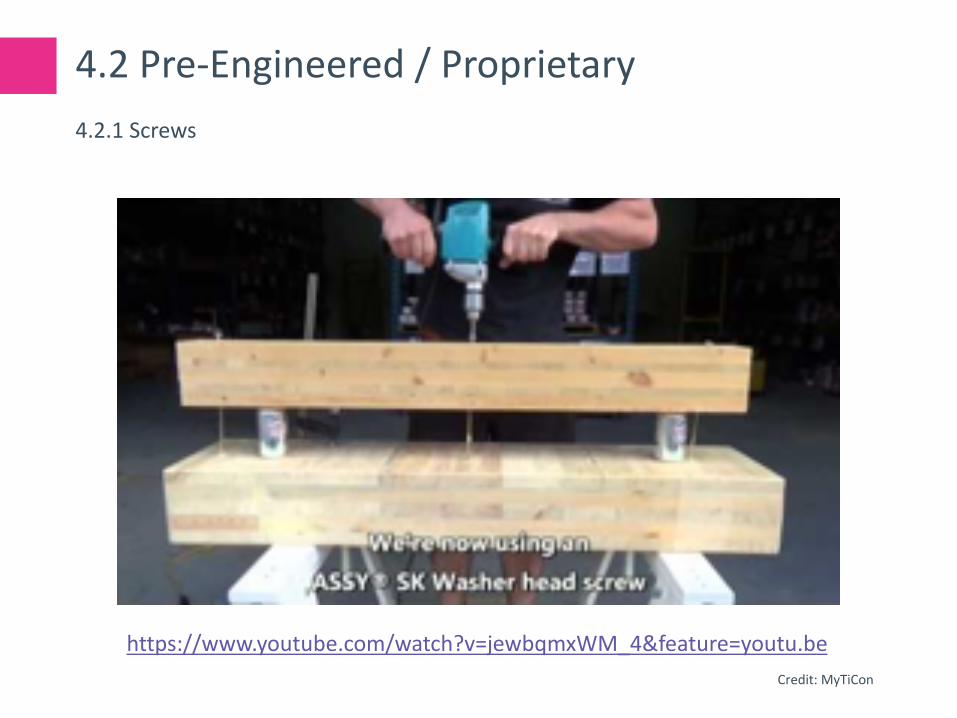
4.2.1 Screws
https://www.youtube.com/watch?v=jewbqmxWM_4&feature=youtu.be
Credit: MyTiCon

4.2 Pre-Engineered / Proprietary
4.2.1 Screws
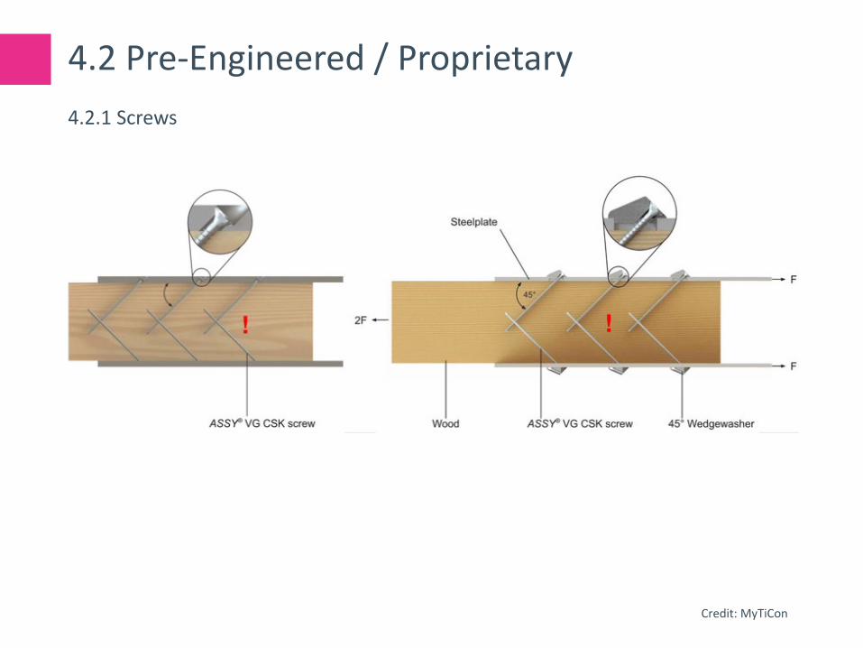
Credit: MyTiCon

4.2 Pre-Engineered / Proprietary
4.2.1 Screws
Credit: MyTiCon
4.2 Pre-Engineered / Proprietary
4.2.1 Screws
Credit: MyTiCon

4.2 Pre-Engineered / Proprietary
4.2.1 Screws

4.2 Pre-Engineered / Proprietary
4.2.1 Screws
Reference: Grazer Holzbau-Fachtagung 2007: Traglast von auf Zugbeanspruchten Schraubenverbindungen mit Stahlblechen https://www.tugraz.at/fileadmin/user_upload/Institute/LIGNUM/Downloads/Unterlagen/06_GraHFT_07_tagungsband.pdf

4.2 Pre-Engineered / Proprietary
4.2.1 Screws
Reference: Grazer Holzbau-Fachtagung 2007: Traglast von auf Zugbeanspruchten Schraubenverbindungen mit Stahlblechen https://www.tugraz.at/fileadmin/user_upload/Institute/LIGNUM/Downloads/Unterlagen/06_GraHFT_07_tagungsband.pdf

4.2 Pre-Engineered / Proprietary
Follow the approvals for spacings!
Group Factors….!? (nef = n0.9)
4.2.1 Screws
Credit: AWC/NDS
4.2 Pre-Engineered / Proprietary
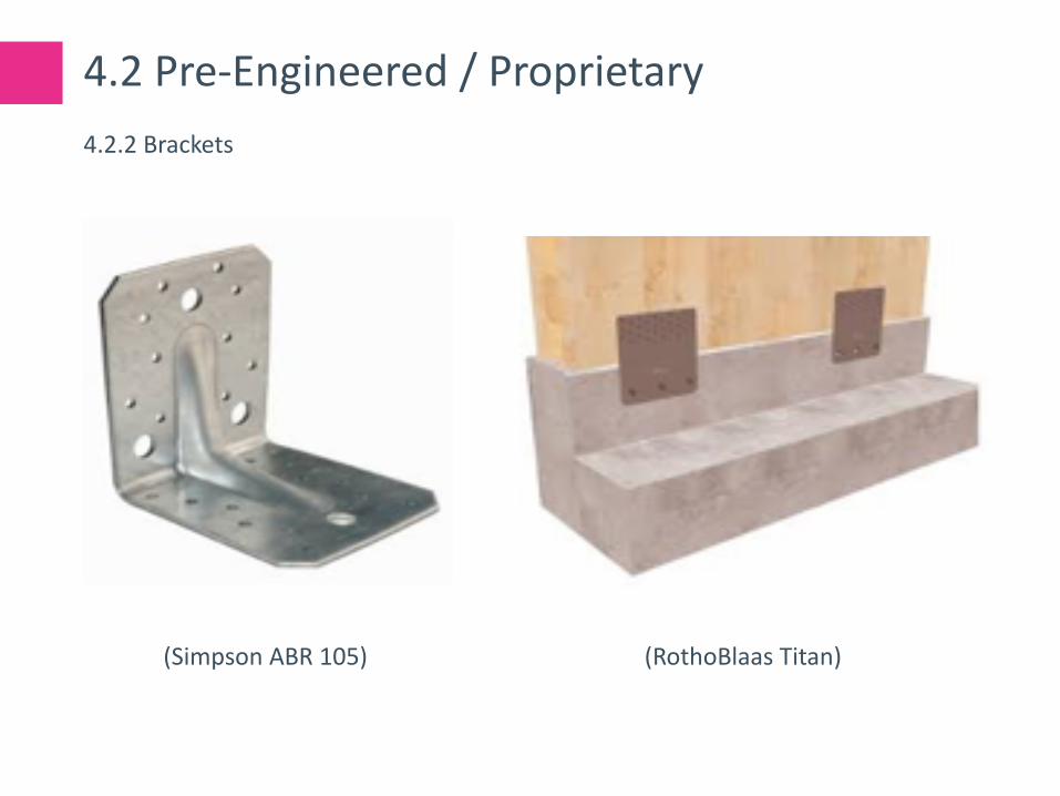
(Simpson ABR 105) (RothoBlaas Titan)
4.2.2 Brackets

4.2 Pre-Engineered / Proprietary
(Rothoblaas X-RAD) (RothoBlaas WHT)
4.2.2 Brackets/Hold-downs

4.2 Pre-Engineered / Proprietary
(Simpson CJT1) (RothoBlaas AluMaxi)
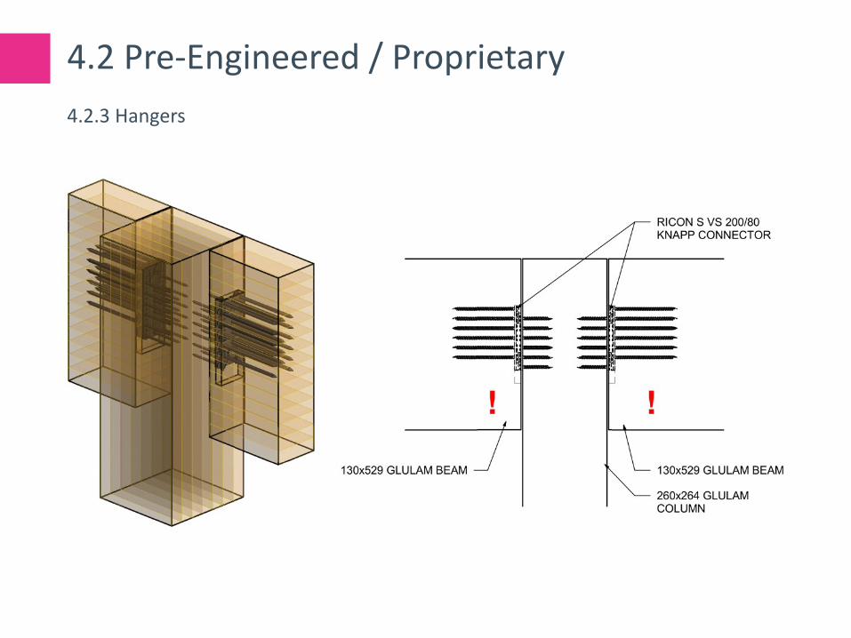
4.2.3 Hangers

4.2 Pre-Engineered / Proprietary
(Knapp Megant)
4.2.3 Hangers

4.2 Pre-Engineered / Proprietary
4.2.3 Hangers
4.2 Pre-Engineered / Proprietary
4.2.3 Hangers

4.2 Pre-Engineered / Proprietary
4.2.3 Hangers

4.2 Pre-Engineered / Proprietary
4.2.3 Hangers

4.3 Custom
Ft,90,d = [1-3 * (he/h)2 + 2 * (he /h)3] * Fv,Ed
with:
Ft,90,d = design tension perpendicular to grainFv,Ed = design connection force
The reinforcing is to be designed for Ft,90,d.
Embedment length for design lad = min {lad,c; lad,t}.
lad,t should extend at least up to 70% of the beam height.
Reinforcement should be placed within an area based on 30° measured from the top of the connection.
4.3.1 Reinforcing

4.3 Custom
• Washer head screws to pull panel flush
• Nails to transfer in-plane shear loads
• Out of plane shear loads to be taken by washer head screw and plywood bending or provide pairs of fully threaded screws (high heads)
• ¾” plywood, 5 3/4 strip. 4’ plywood sheet will yield 8 strips with minimal waste
4.3.2 CLT to CLT Surface Spline

4.3 Custom
• CLT Hold-down connection
• Internal knife plate
• 6mm self-drilling screws
• Strong, but ductile connection
• Shop-installed with special equipment
4.3.3 Hold-down connection

5.0 Next Generation

5.1 Adhesive Connections
5.1.1 Glued in Rods

5.1 Adhesive Connections
5.1.2 HSK

5.1 Adhesive Connections
5.1.3 TS3.0 – Glued Butt Joints

5.1 Adhesive Connections
5.1.4 Glued and screwed

5.2 Timber-Concrete Composite Systems

Further Resources

Load-carrying behaviour of steel-to-timber dowel connections; Adrian Mischler, Helmut Prion, Frank Lamhttps://pdfs.semanticscholar.org/bd4b/a80168b8d48ab053ca29960ddb4842136041.pdf
Grazer Holzbau-Fachtagung 2007: Traglast von auf Zugbeanspruchten Schraubenverbindungen mit Stahlbleche; H. Krenn, G. Schickhofer https://www.tugraz.at/fileadmin/user_upload/Institute/LIGNUM/Downloads/Unterlagen/06_GraHFT_07_tagungsband.pdf
Self-tapping screws and threaded rods as reinforcement for structural timber elements – A state-of-the-art report; Philipp Dietsch, Reinhard Brandner
EN 1995 design of timber structures (Eurocode 5)
à See also supplier specific documents and white papers
Further Resources

This concludes the American Institute of Architects Continuing Education Course.
Questions?
Duncan [email protected]