Embed Size (px)
Citation preview
_lDOD-STD~jj37(SH)13AprilI“w2-
MI IITARY STANDARD
MASS PROPERTIES
TECHNICAL REQUIREMENTS
FOR SURFACE SHIPS
(METRIC)
,0
0,@
o AMSC No.!N3134
AREA MISC
*
Downloaded from http://www.everyspec.com

.
“DOD-.STD-2137(SH)13 April 1982 I
DEPARTMENT OF DEFENSE
“Washington, DC 20362
Mass Properties Technical RequirementsfOr Surface Ships
DOD-s TD-2137 (SW),.
,),’
1. This Military Standard is approved for use by the Naval seaSy3tems Command, Department of the Navy, and is ’available for use by allDepartments and Agencies of the Department of Defense.
2. Beneficial cornments’-(recoin;eridations’,,additions, deletions) andany pertinent data which may be of use in improving this document should beaddressed to: Commander; Nav,al Sea Sy;tems,Comrnand, SEA 3112, Departmentof the Navy, Washington, DC 20362”by using the”.self-addressed Standardi-zation Document Improvement Proposal (.DD Form 1426) appearing at the end ofthis document or by letter.’ ,..,.”
.,,
,.
,...,.
., ..:. ,.,
ii
.’.:, ..........: ..:. ,..;.:,:.,,..~.:,:.:, ,.../,...’:....... “.,,,.
Downloaded from http://www.everyspec.com

_—
DOD-STD-2137(SH)13 April 1982
‘IFOREWORD
Purpose. The purpose of this standard is to delineaproperties technical requirements for surface ships.
te the mass
Background. This standard satisfies a requirement to combine allmass properties control technical requirements for s1l Dhases of U.S. Navysurface ship acquisition contracts i;to a single document.
Concept. This standard includes pertinent definitions and massproperties report content and procedures for both the pre-detail design anddetail design, and construction phases. All sections are self-sufficientin technical coverage: however, they must be considered in conjunction withthe policy and procedures of the basic document to be applied effectively.
Benefits. This standard defines mass properties technical require-ments and discusses different types of mass properties estimates andreports. It will assist in achieving more uniformity by standardizing themass properties reporting systam.
,
iii
Downloaded from http://www.everyspec.com
‘DOD-STD-2137(SH)13 April, 1982
CONTENTS,,.
Paragraph 1.1.11.2’
2.2.12.2
3.3.1
3.23.33.43.53.63.73.83.93.10
3.113.123.133.143.15
3.163.173.183.193.203.213.22
3.233.243.25
3.26
3.273.283.293.303.313.32
SCOPE . . . . . . . .Scope . . . . . . .Reports interface .
REFERENCED DOCUMENTS .Issues of documentsOther publications .
DEFINITIONS . . . . .
. . . .
. . . .
. . . .
. . . .
. . . .
. . . .
. . . .Accepted mass properties eSt(’AMPF) . . . . . . . . . .
Accepted ship report . . . .Acquisition margin . . . . .Actual mass . . . . . . . .Baseline mass properties estCalculated mass . . . . . .
. . . . . .
. . . . . .
. . . . . .
. . . . . .
. . . . . .
. . . . . .
. . . . . .mate. . . . . .. . . . . .. . . . . .. . . . . .mate . . .. . . . . .
Capacity load condition (condition E) .Category. . . . . . . . .. . . . . . .Category system . . . . . . . . . . . .Contractd ata requirements list(CDRL)” - DDForm 1423 . . . . . . . . .
Contract design margin . . . . . . . . .Contract design mass properties estimateCon{ract modi~ication margin . . . . . .Contract modification report . . . . . .Contractorts design mass propertiesestimate . . . . . . . . . . . . . . .Current mass . ~ ; . , . . . . . . . . .Density factors:.. . . . . . . . . . . .Design and mass properties data sheet .Design data package . . . . . . . . . .Detail design and building margin . . .Estimated mass . . , . . . . . . . . . .Feasibility design mass propertiesestimate . . . . . . ;.. . . . . . . .
Final mass properties report . . . . . .Full load condition (condition D)Government-furnished material (GFM)” “ “margin . . . . . . . 1 . . . . . . . .
Government-furnished material (GFM)report .. . . . . . . . . . . . . . .
Group . .’. . . . . . . . . . . . . . .Inch-pound units . . . . , . . . . , , ,Inclining experiment . . . . . . , . . .Input,data cards . . . . . . . . . . . .Light ship condition (condition A) . . .Longitudinal lever . . . . . , . . . . .
!s.!3s1‘1
1
111
2
222222233
33333
333Q4u4
444
5
5555556
iv
Downloaded from http://www.everyspec.com
DoD-sTD-2137(sH)13 April 1982
CONTENTS (Continued)
Paragraph 3.333.34
3.353.363.373.383.393.40
3.413.42j.433.4U3.453.46
4.4.14.24.2.14.2.24.2.34.2.44.2.54.2.64.2.74.2.84.2.94.2.104.2.114.2.124.2.134.3
5.5.15.1.15.1.1.15.1.1.25.1.1.35.1.2
i
5’.1.2.15.1.2.25.1”.2.35.1.2.45.1.2.55.1.2.65.1.2.75.1.2.8
Mass distribution . . . . . . . . . . .t.tassmoluent, . . . . . . . . . . . . . .Mass properties control . . . . . . . .Mass properties data . . . . . . . . . .Mass properties reporting . . . . . . .Percent completion . . . . . . . . . . .Preliminary design margin . . . . . .,.Preliminary design mass propertiesestimate . . . . . . . . . . . . . . .
Quarterly mass properties report . . . .SI units. . . . . . . .’. . . . . . . .Standard longitudinal station breakdownThree-digit system . . . . . . . . . . .Transverse lever . . . . . . . . . . . .Vertical lever . . . . . . . . . . . . .
GENERAL REQUIREMENTS . . . . . . . . . . .Determination of mass properties data .General report requirements . . . . . .Loading conditions . . . . . . . . . . .Margins . . . . . . . . . . . . . . . .Three-digit ‘iystem” . . . . . . . . . . .Summaries . . . . . . .’. . . . . . . .Mass moment of inertia . . . . . . . . .Reporting system units . . . . . . . . .Mass properties changes . . . . . . . .Table of contents . . . . . . . . . . .Special coding . . . . . . . . . . . . .Lever symbol. . . . . . . . . . . . . .Mass properties data . . . . . . . . . .Paper . . . . . . . . . . . . . . . . .Supporting documents . . . . . . . . . .Classified reports . . . . . . . . . . .
DETAIL REQUIREMENTS . . . . . . . . . . .Pre-detail design phase . . . . . . . .Mass properties estimatea and. reports .Design mass properties estimates . . . .Baseline mass properties estimates . . .Interim mass properties reports . . . .Supplemental documents . . . . . . . . .Top level specification input . . . . .Ship Specifications sectionContract data requirements li;t”(&D~Lj :Design notebook - maas properties . . .Schedule ‘At! mass properties input . . .Masa properties trade-off studies . . .Input data cards . . . . . . . . . . . .Mass distribution report . . . . . . . .
~
6666666
6677777
77788888
:9999999
1010101010101111111111121212
.12
v
Downloaded from http://www.everyspec.com

DOD-STD-2137(SH)13 April 1982
CONTENTS (Continued)
Paragraph ‘5.25.2.15.2.1.15.2.1.2
5.2.1.35.2.1.4
. 5.2.1.55.2.1.65.2.25.2.2.15.2.2.25.2.2.35.2.2.4
5.2.35.2.3.15.2.3.25.2.3.35.2.3.U5.2.3.5
Figure ,... ‘
2.
3.
4.
5.
6.
Appendix AB
Detail design and construction phase . .Mass properties estimates and reports .Determination of mass. properties data .Contractor?a design ❑ ass propertiesestimate . . . . . . ... . . . . . . .
Accepted m’ass properties estimate . . .Baseline mass properties estimate(BLMPE)”. . . .“. . . . . . . . . . . .
Quarterly mass properties report . . . .Final mass properties report . . . . . .Supplemental mass properties reports . .GFMreports ... . . . . . . . . . . . .Contract modification report . . . . . .Accepted ship report . . . . . . . . . .Machinery m,asa properties report(nuclear) . .. . . . . . . . . . . . .
Supplemental documents . . . . . . . . .Mass properties control plan . . . . . .Mass properties design dsta, sheet . . .Mass distribution report .:. . . . . . .Input data ’cards . . . . . . . . . . . .Mass propertiest rade-off studies . . .
FIGURES
Interface of mass properties ‘reports indesign and construction . . . . . . . . .
Contract modification summary (accepted’mass properties estimate) . . . . . . . .
Contract, ❑edification summary .(baselinemass properties estimate) . . . . . . . .Accepted ship report (accepted massproperties estimate) . . . .’. . . . . .
Accepted ship report (baseline massproperties estimate) . . . . . . . . . .
Mass properties design dats sheet format .
APPENDICES
Input ‘data card format . . . . . . . . . .Data requirements . . . . . . . . . . . .
&.Ms
121313
1414
15151516161718
18191920202020
21
22
23
24
2526
2937
vi
Downloaded from http://www.everyspec.com

DOD-STD~2137(SH’)13 April 1982
1. SCOPE
1.1 Scope. This standard establishes mass properties estimate andreport content and procedures for all design phases of surface shipacquisition including: feasibility studies, preliminary de$ign,. contractdesign, detail design, and construction.
1.2 Reports interface. The interface of mass properties estimatesand reports is depicted in figure 1.
2. REFERENCED DOCUMENTS
2.1 Issues of documents. The following documents, of the issue ineffect on date of invitation for bids or request for proposal, form a partof this standard to the extent specified herein.
1 STANDARD
MILITARYI DOD-STD-1690 - Maritime Metric Practice Guide.
I PUBLICATIONS
NAvAL SEA SYSTEMS COMMAND (NAVSEA)o9OO-LP-O39-9O1O - Ship Work Breakdown Structure.0900-LP-039-9020 - Ship Work Breakdown Structure for Nuclear
Propulsion Plant (U).0902-LP-O02-2000 - Bureau of Ships Consolidated Index of
Drawings, Materials and Services Relatedto Construction and Conversion.
(Copies of specifications, standards, drawings, and publicationsrequired by contractors in connection with specific acquisition functionsshould be obtained from the contracting activity or as directed by thecontracting officer. )
2.2 Other publications. The following document forms a part of thisstandard to the extent specified herein. Unless otherwise indicated, theissue in effect on date of invitation for bids or request for proposalshall apply.
AMERICAN NATIONAL STANDARDS INSTITUTE; INCi (ANSI)X3.4 - Code for Information Interchange.
(Application for copies should be addressed to the American NationalStandards Institute, Inc., 1430 Broadway. New York, NY 10018.)
(Technical society and technical association specifications andstandards are generally available for reference from libraries. They arealso distributed among technical groups and using Federal agencies.)
1
Downloaded from http://www.everyspec.com
DOD-STDA2137(SH)13 April 1982
D
3. DEFINITIONS
3.1 Accepted mass properties estimate (AMPE). AMPE is the bestevaluation of the ship with respect to mass and the vertical, longitudinal,and transverse location of the center of grsvity. It is derived by compar-ison and analysis of the contract design mass properties estimate and thecontractors design mass properties estimate.
.,..
3.2 Accepted ship report. An accepted ship report includes thedisplacement, height of the ship~s center of gravity above the bottom ofthe keel (KG), trim, and list values of the inclining experiment prelimi-nary report, from.which the net mass properties effect of adjudicated andunadjudicated contrsct modifications and mass.properties changes due toGovernment-furnished material (GFM) nave been .algebraically subtracted.
3.3 Acquisition margin. Acquisition margins are mass and KG allow-ances included in the mass properties estimates to cover the inherentlimits of precision and the undefined variations of component mass andcenters of gravity that take place throughout the design phases and duringthe construction of a ship. In order to provide for adequate massproperties control and configurations control, acquisition margins aredivided into five elements: preliminary de”?ign margin,, contract designmargin, detail design and building margin, contract modification margin,and GFM margin.
3.4 Actual mass. Actual mass is the value obtained by an actualmeasurement of material on a scale.
3.5 Baseline mass properties estimate. Baseline mass propertiesestimate is the mass properties. estimate of the light ship, full load,capacity load, and any other specified load condition prepared during thefunctional preliminary allocated, or allocated baseline design phase.
3.6 Calculated mass. Calculatedmass is maas computed from shipconstruction drawings and vendor drawings.
3.7 Capacity load condition (condition”E). The capacity loadcondition is the ship complete and ready for service in every respect.It is light ship (condition A) plus the following variable loads: maximumnumber of officers, crew, and passengers that can be accommodated and theireffects: maximum stowage of ammunition in magazines and ready servicespaces: full allowance of aircraft andvehicles(empty mass with, fullallowance of repair parts and stores): maximum amount of provisions andstores that can be carried in the assigned spaces: and maximum capacity ofliquids in tanks. Fuel and lube oil shall not exceed 95 percent of tankcapacity, unless such tanks are compensating. Compensating tanks shall beconsidered filled with 95 percent fuel.and 5 percent salt water. Maximumamounts of cargo and supplies, other than for shiprs own use, shall beincluded to the full capacity of the assigned spacea. This load conditionshall not exceed the limiting drafts.
2:,i
Downloaded from http://www.everyspec.com

DOD-STD-2137(SH)13 April 1982
3.8 Category. Category is a fundamental unit of machinery massclassification for nuclear-propelled ships as defined in NAVSEA0900-LP-039-9020 .
3.9 CategOrY system. Category system Is a system of machinery massclassification for nuclear-propelled ships as defined in NAVSEA0900-LP-039-9020.
3.10 Contract data requirements list (CDRL) - DD Form 1423. A CDRLis a contract form listing all data items selected from an authorized data
--—
list to be delivered under the contract. It includes the frequency, sub-mittal and distribution requirements.
“3.11 Contract design margin. Contract design margin is a mass andKG allowance inclutied in the mass. properties estimate to account forincreases associated with design development during the contract designphase. This margin is carried in the feasibility and preliminary designphaaes. No portion> of this margin is consumed prior to the start of con-tract design, nor is any unused margin carried over into the next designphase.
3.12 Contract design mass properties estimate ..Contract design massproperties estimate ia the mass properties estimate of the light ship, fullload, capacity load and any other specified load condition prepared duringcontract design phase.
3.13 Contract modification margin. Contract modification margin isa mass and a KG allowance included in the mass properties estimates andreports to account for increases associated with contract modificationsissued during the detail design and construction phase. No portion of thismargin is consumed prior to award of the detail design and constructioncontract.
3.14 Contract modification report. Contract modification report isa complete listing of contract modifications that supplements the quarterlymass properties report, accepted ship report, and final mass propertiesreport. It constitutes a statement of adjudicated, and currently unadjudi-cated, mass properties values that will be used to modify the displacement,KG, list, and trim of the accepted mass properties estimate or baselinemass properties estimate.
3.15 Contractorts design mass properties estimate. Contractor’sdesign masa properties estimate. is the mass properties estimate prepared bythe contractor at the beginning of the detail design and constructionphase, based on Ship Specifications and all documents referenced therein.
3.16 Current mass. Current mass is the sum of a combination of thelatest estimated, calculated, or actual mass for all items.
3.17 Density factors. Density factors are factors by which the massof variable loads may be computed. These factors are included in thedesign data package.
3
Downloaded from http://www.everyspec.com

DOD-STD-2137(SH)13 April 1982
3.18 Design and mais properties data. sheet. Design andmass proper-ties data sheet iS a mass properties data.sheet$rwhich includes general ●data, hull characteristics data, displacement. and stability characteristicsdata, load data, and machinery data as are appropriate to the ship.
3.19 Design data package. Design data’ package is a package ofdesign information, usually containing curves of form, endurance require-ments, density factors, the.group summary of the contract design mesaproperties estimate without margin?, -and,Bonjean curveg which is furnishedto the,contractor after award of contract. :
3.20 Detail design and building matigin. Detail design and buildingmargin is a.mass and KG allowance,included .in the mass properties estimatesand reports to account for design changes to the current mass due to shipconstruction drawing.development , growth of contractor-furnished material,omissions and errors in the accepted “or baseline mass properties estimate,as well as differing shipbuilding practices; omissions and errors in theahip construction drawings, unknown mill tolerances outfitting details,variations between the actual ship and ‘its”curves of form and similardifferences. This margin is to compensate for all contractor-responsiblediscrepancies between the contract designer baseline masa propertiesestimate and the results of the inclining experiment, as well as tolerancesfor experimental variation in the inclining experiment. This mass and KGallowance is carried in the feasibility., preliminary, and contract designphases but no portion of this margin is consumed prior’to award of thedetail design and constru@tion,contract: .H.owever,the actual value< formass as well as location for the design and building, margin is,likely tochange at.the start of the detail design phase becauae this margin repre-sents an allowance that is ac’tually.the Icontractort.a responsibility. Thusit.~s subject to negotiation with the contractor selected for detai~ design ●and construction.
3.21,, Estimated mass. .Estimated mass’is based on Ship Specificationsand preliminary data, includ.i”g estimated. ~aas “al”es Of GFM..
3.22 Feasibility .design mass properties: estimate. Feasibilitydesign mass properties estimate is”the.mass properties estimate of thelight ship, full load, capacity .load “and any”other specified load conditionprepared during the feasibility design phase;,.
3.23 .“Final mass properties report. Final mass properties report isa detailed ? na~i es data, for all required loadingreporconditions. This report accurately refleot$ accumul.at~d values fOr ~sti-mated, calculated, and actual mass pt?operties data for design developmentincluding ,the net effect of ohanges for GFM and for adjudi~~ted. a“d ~~adju.dicated contract modifications.
,!,
3.24 .Full load condition (condition D). The CU1l load condition is
the ship complete and ready for service in every respect. It ia light ghip(condition A) plus the ‘following yarlable loads: authorized complement ofofficers, crew, and passengers, and their effects: full allowances of
4
Downloaded from http://www.everyspec.com
DOD-STD-2137(SH)13 April 1982
ammunition in magazines and ready service spaces: full allowance of air-craft and vehicles (empty mass with full allowance of repair parts andstores): full supply of provisions and stores for the periods specified inthe design characteristics; fuel in amount necessary to meet endurancerequirements: anti-roll tank liquid; and all other liquids in tanks torequired capacity in accordance with characteristic and existing liquidloading instruction. The ammunition, stores, fuel and other liquidsreferred to above are for the ship!s own use. Cargo (liquid and solid) isincluded in amounts normally carried or to the specified portion of’thefull capacity of the assigned spaces.
3.25’ Government-furnished material (GFM) margin. GFM margin is amass and KG allowance included in the mass properties estimates and reportsto account for increases caused by,the growth in GFM during the detaildesign and construction phase. No portion of this margin is consumed priorto award of the detail design and construction contract.
3.26 Government-furnished material (GFM) report. GFM report is alist of GFM mass properties data at the time of award of the contract whichis updated
3.27identified
to indicate any changes to these data.
=. Group is a fundamental unit of ship classification,by one numeric digit or an alphabetic designator.
3.28 Inch-pound units. The inch-pound units for this standard is asystem of units using pounds, long tons, feet, foot-pounds, and foot-tonsfor reporting mass properties data. These data are carried to the nearestpound and foot-pound at all detail levels. In addition, summaries areconverted and reported to the nearest one-hundredth of a long-ton and to.the nearest foot-ton. All levers are carried to the nearest one-hundredthof a foot.
3.29 Inclining experiment. The inclining experiment is the proce-dure for determining the height of the ship?s center of gravity byobserving the inclination produced by a known transverse mass moment andfor determining the displacement and fore-and-aft position of the ship!scenter of gravity by observing the drafts.
3.30 Input data cards. Input data cards are detailed mass proper-ties data on punched cards which comply with the Navy standard computerprogram format and are used by NAVSEA to prepare Navy mass propertiesestimatea and reports.
3.31 Light ship condition (condition A). The light ship conditionis tha ship complete and ready for service in every respect, including per-manent ballast (solid and liquid), on-board repair parts, aviation mobilesupport equipment as assigned, “and liquids in machinery at operatinglevels, without any items of variable load. This condition represents theship under wartime conditions, with ultimate armament but peacetime boatallowance aboard.
5
Downloaded from http://www.everyspec.com
.
DOD-STD-2137’(SH)13 April 19”82
3.32 Longitudinal lever. Longitudinal lever is the perpendiculardistance from a transverse plane’ thr’ough the longitudinal reference datumof the sh$p to the center of gravity. of an item. ,This reference datum ●shall be located at the forward perpen”dicular,.unless otherwise specified bythe design contract or “the”Ship Specifications (Section 096).
3.33 Mass distribution. Mass ’distribution’ is the mass distributionof a ship’s hull, cargo,. armament, etc., measu”red by the standard longitu-dinal ,station breakdown to develop shear forces and bending moments.
lever?”34Mass moment. Mass moment is the product of a mass and its
For example, the longitudinal mass morne~ntof an item 13 the productof the mass of the item multiplied .by its longitudinal lever.
3.35 Mass properties control., Mass p,rope~ties control is all theaction necessary (e.g., predicting; 6st+’mating, calculating, actual massdetermining, reporting, analyzing, and “evaluation) to ’ensure that theshipt.s mass proper ties .data are consistent wit,h the values agreed upon fordisplacement,. KG, list, andtr.im in the accepted; or baseline mass proper-ties estimate.
3.36 Mass properties data. Mass properties data are those physicalproperties which inclade mass, c,enter of g’r’syit.ylocation, ma,ssmoments,moments of inertia and products of irierf.ia,whose values are required tocontrol those characteristic’s’that.collectively determine performance andstability. : ..
.
3.37 Mass properties reporting. Mass properties reporting is thatpart of mass properties control ,which constitutes .the,technical presenta-tion of the best known mass properties. data”, at.periodic designated timesthroughout the design and building proces?e”s. ●
3.38 Percent completion. Percent completion isthe ratio of thecurrent mass less the current estimated m’ass,p”orti.on,to the current mass,expressed as a percentage.
. ..
3.39 ~. Preliminary”design margin is a massand KG allowance included in the mass properties estimates to account forincrea$es associated with design development during the preliminary designphase.. This margin is carri’ed in the feasibility design phase. No portionof this margin is consumed prior to the’ it,art.:ofpreliminary design, nor isany unused niargin carried over into the next design phase.
3.40 Preliminary design mass properties estimate. Preliminarydesign mass properties estimate is .ttiemass properties estimate of thelight ship, full load, capacity load, and any other specified load condi-tion prepared during the preliminary design phaS.e.
3.41 Quarterly mass properties report. Qu’ar’te’ilymass propertiesreport is a summarized mass properties report “based on the accepted orbaselinem ass properties estimate. It reflects. accumulated values for
6
Downloaded from http://www.everyspec.com

I
DOD-STD-2137(SH)13 April 1982
estimated, calculated, and actual mass properties data for design develop-ment, including the net effect of changes for GFM and for adjudicated andunadjudicated contract modifications.
3.42 SI units. S1 units (International system of units) (seeDOD-STD-1690) for thi$ standard is a system of units using kilograms,metric tons, metars, kilogram-metars and metric ton meters for reportingmaas property data. These data are carried to the nearest kilogram andkilogram-meter at all detail levels. In addition, summaries are convertedand reported to the nearest one-hundredth of a metric ton and to thenearest metric ton-meter, All levers are carried to the nearest one-hundredth of a mater.
3.63 Standard longitudinal station breakdown. Standard longitudinalstation breakdown is a mass distribution breakdown system consisting oftwen,ty-two,stations designated by the letters A thro~gh X (excludin~ I ando). Each station space is 1/20 of the length between perpendiculars.Station A’is the only station forward of the forward perpendicular (FP).Station X is the only station aft of the aft perpendicular (AP). StationsB through W extend from the FP to the AP.
3.44 Three-digit system. Three-digit system is a system for shipC1aSSifiCatiOn defined in NAVSEA 091)0-Lp-039-9010, NAVSEA lJ900-Lp-039-9020,or NAVSEA 0902-LP-002-2000, as applicable.
3.45 Transverse lever. Transverse lever is the perpendicular dis-tance from ‘fhe vertical centerline plane of the ship to the center ofgravity of an item.
3.46 Vertical lever. Vertical lever is the perpendicular distancefrom a horizontal plane through the molded baseline of the ship to thecenter of gravity of an item.
4. GENERAL REQUIREMENTS
4.1 Determination of mass properties data. As ship design or shipconstruction drawings are prepared and as material is selected. acQuired,or received, the mass and centers of gravity of all items that-comprise theship shall be determined and reflected in the mass properties estimates andraports. In addition, the mass properties data for all components andmaterial, and their overall effect on the ship,s displacement, center ofgravity, list, and trim shall be determined. These data may be obtained byestimation or calculation during feasibility, preliminary and contractdesign, and by a combination of estimation or calculation of ship construc-tion drawings and by actual mass determination of items during detaildesign and construction.
4.2 General report requirements. The ,design contract or the ShipSpecifications (Section 096) will invoke this standard and will establishtechnical data to be prepared, modifications, or exceptions. The contractdata requirements list (CDRL) will establish requirements for deliverablessuch as: submittal data, frequency of Submittal, number of copies, and
7
‘o
L-
Downloaded from http://www.everyspec.com

,,
DoD-sTD-21j-’f(sH)13 April “1982
recipients. The general require’mentisfor the mass properties estimates andreports listed in this standard shall be in accordance with the criteria ●specified in 4.2.1 through 4.3. The estimates and reports shall be asspecified in the CDRL.
4.2.1 Loading conditions. Loadi,ng;condit’ion: normally required willbe light ship, full load, and Capacity load conditions. However, suchrequired .16ading conditions for a specific ship will be specified in thedesign contract or Ship Specifications (Section 096).
4.2.2 Margins. Required acquisition margins shall be included inthe estimates and reports. Departures from original baseline values arereflected by concurrent adjustments to the appropriate acctuisition marginaccount. Acquisition margins are required during pre-detail design phase.Normally, only the detail design and’building margin is required duringdetail design and construction phase. Additional margins, if required,will be specified in the”Ship Specifications (Section 096).
4.2.3 Three-digit system. Item”s shall be;grouped in aQcorda”=e “iththe three-digit system. To demonstrate tbe amount of detail required, anexample will be furnished upon request and will consist of a typical massproperties estimate in which all mass’, lever, and mass moment values havebeen deleted. This example may also be used as a guide for determinationof classification grouping. Normally, the three-digit system to be used is‘Ship Work Breakdown Structur e,, (SWBS). An alternative system, the lvBureaxof Ships ’Consolidated Indexf? (BSCI), will be specified in the designcontract or Ship Specifications (Section 096) if applicable.
4.2.4 Summaries. Summaries shall be inclqded for all requiredloading oonditlona and their associated drafts (forward, aft, and mean),list, trim,
●KG, and metacentric height (GM), uncorrected and corrected for
free surface effect of liquids in tanks (with and without the net effect ofadjudicated and unadjudicated contract modifications, and net mass and mass
moment changes in GFM).~’
4.2.5 Mass moment of inertia: Wfien specifically required by theShip Specifications (Section. 096), mass moment of in.4rtia data for eachloading condition of the ship shall be included: Current detail data andengineering information shall be used to develop this mass “ome”t Ofinertia data. The minimum data to be included are as follows:
(a) .Roll, pitch, and yaw moments of”inertia about the centroidalaxes.
(b) Principal axes inclinations.(c) Roll, pitch, and yaw moments of inertia about the principal
axes.
~’This portion is not applicable to pre-detail design phase estimates orreports.
8
Downloaded from http://www.everyspec.com

,.
@
DOD-STD-2137(SH)13 April 1982
4.2.6 Reporting system units. Unless otherwise specified, esti-mates, reports, and other specified mass properties documentation and datashall utilize S1 units. The design contract or the Ship Specifications(SeCtiOn 096) will invoke the inch-pound units when applicable.
4.2.7 Mass properties changes. The mass properties report’s shallinclude reasons fOr mass properties changes (in accordance withthe three-digit System) from the previou S estimates and reports, and shall alsoinclude recommendations for reversing unsatisfactory trends towardexceeding the established margins or limits. Reasons for mass propertieschanges are only required for the second and subsequent reports within adesign phase.
4.2.8 Table of contents. The estimates and reports shall contain atable of contents.
0.2.9 Special coding. An explanatory note and remark section shallbe included %0 define special coding symbols such as: material codes, GFMindicators, and reasons for change indicators.
4.2.10 Lever symbol. Vertical levers shall be indicated by ‘~-n forbelow the baseline, and ‘+**or blank for above the baseline. Longitudinallevers shall be indicated by ‘F!vor ‘-V* for forward of the reference plane,and 11A*8or W+n or blank for aft of the reference plane. Transverse leversshall be indicated by llP*Sor W+N or blank for port, and T9AWor TV-Mforstarboard.
4_.2.11 Mass properties data. Estimates and reports, ahall be indetail and shall include latest evaluation of mass data and vertical, lon-gitudinal, and transverse levers and mass moments for each item.
4.2.12” ~. The estimates and reports shall be machine written onpaper no larger than 23o millimeters by 355 millimeters (9 inches by 14inches) and shall be protected by hard covers but not permanently bound.The original or reproducible copy shall be suitable for microfilming.
4.2.13 Supporting documents. ‘Background information studies, direc-tives, correspondence , and all detail calculations pertaining to mass prop-erties data, including density factors, shall be included in the submittalof the estimate or report. These documents are not required to be sub-mitted with interim reports, unless specifically requested by the designcontract.
4.3 Classified reports. Mass properties reports containing confi-dential data shall be ❑arked in accordance with security requirements ofthe contract. Whenever possible, classified or proprietary material ordata shall be downgraded by deleting classified or proprietary portionsthat do not impair the usefulness of the document.
9
Downloaded from http://www.everyspec.com
DOD-STD-2:137(SH)13 April 1982
:. 5. DETAIL REQURIEMENTS
5.1 Pre-detail design phase. Estimates, reports, and supplementaldocuments for this design phase shall be in accordance with 5.1.1, unlessotherwise so stated.
5.1.1 Mass properties estimates and reports. Mass properties esti-mates and reports prepared during. this phase typically consist of designmass properties estimates or baseline mass properties estimates, andinterim reports. These estimates and reports are in detail and summarizedin tabular form as follows:
(a)(b)(c)(d)(e)(f)(g)(h)(i)
Three-digit system number and title.Original mass.Current mass.Current vertical lever..Current vertical mass moment.Current longitudinal lever.Current longitudinal” mass moment.Current transverse lever.Current transverse mass moment.
The mass properties data included in these estimates and reports are basedon the characteristics, applicable specifications, and preliminaryinformation.
5.1.1.1 Design mass properties estimates. The final estimate pro-duced during a given design phase is designated. the-design” masa Propertiesestimate. This estimate will reflect ’the appropriate title, such as:Feasibility Design Mass Properties Estimate, Preliminary Design Mass Prop- 0erties Estimate or Contract Design Mass Properties Estimate. The require-ments for the estimates are as outlined in 5.1.1 above.
.,,”5.1.1.2 Baseline mass properties ’estimates: The final estimate pro-
duced during a given baseline design phase is designated the baseline massproperties estimate. This estimate will reflect the.appropriate title,such as: Functional Baseline .Mass.Properties Estimate, Preliminary Allo-cated Baseline .Mass Properties Estimate or Allocated Baseline Mass Proper-ties Estimate. The requirements for the”estimates are as outlined in 5.1.1above. ,.
5.1.1.3 Interim mass properties reports. Mass properties estimatesproduced periodically during a given design or baseline phase are desig-nated interim mass properties reports, “except the final report of the phaseis designated the design or baseline mass properties e$timate. Thisinterim report summarizes the current mass properties status of the designand highlights changes that occurred in the reporting period. The reportsprovide a comparison between estimated mass properties data and the
10
Downloaded from http://www.everyspec.com

‘o
I
DOD-STD-2137(SH)13 April 1982
constraints necessary for a satisfactory ship design with respect to dis-placement, KG, list, and trim. The report shall reflect the appropriatetitle, such as: Preliminary Design - Interim Mass Properties Report, orFunctional Baseline - Interim Mass Properties Report. The report shallcontain the following:
(a) Previous design phase group level summary.(b) Previous report group level summary.(c) Current group level estimate and, when required, the element
level estimate and longitudinal mass distribution data.(d) Net change, by group and total, between (a) and (c) above.(e) Net change, by group and total, between (b) and (c) above.(f) Margin status, loads, full load displacement, KG, list, and
trim changes corresponding to net changes calculated for(d) and (e) above.
(g) A brief narrative providing reasons for significant changesince previous report classified by group and element inwhich the change occurred.
5.1.2 Supplemental documents. The supplemental documents specifiedin 5.1.2.1 through 5.1.2.8 shall provide additional information, mass prop-erties data calculations and background data during the pre-detail designphase.
5.1.2.1 Top level specification input. Inputs to provide informa-tion to the top level specification (TLS), regarding mass properties andcenter of gravity constraints in the design as well as to establish themass properties control program for the ship acquisition process. Thisspecification shall include the constraints on displacement, KG, list andtrim for light ship, full load, and capacity load. List and mass proper-ties control actions to be developed for the design, such as reportingprocedures and an engineering management plan for mass properties controlhighlighting sensitive aspects shall algo be included.
5.1.2.2 Ship Specifications section. The Ship Specifications sec-tions shall be in the form of marked-uD comDuter baseline specification
~. .
sections unless otherwise approved by the cognizant NAVSEA code. Specifi-cally, the required loading conditions. mass Properties reporting units.the required three-digit system, margins to be included and moni~ored, andother special requirements are established and invoked.
5.1.2.3 Contract data requirements list (CDRL). A CDRL will bedeveloped during the pre-detail design phase for the detail design andconstruction phase and will become part of the ship acquisition contract.
5.1.2.4 Design notebook - mass properties. The design mass proper-ties notebook ~ n chronological order, events that occurredduring the design development (including margin determination) with citedreferences to studies and reports, as applicable. This notebook documentsthe evolution of the ship design, while highlighting the major problemareas and resolutions encountered during the design as reflected in thedevelopment of the ❑ ass properties estimate. In addition, the design
11
Downloaded from http://www.everyspec.com

DOD-STD-2137(SH)13 April 1982
notebook documents the mass properties issues and decisions related to thedevelopment of the mass process. All information used in the developmentof the estimate, such as engine efts notes, memoranda, records of telephoneconversations, material equipment lists, factors and equations, shall becontained in the design notebook so as to form a complete historical recordand background supporting the mass properties estimate and design history.All pertinent mass properties data shall be included in tabular form forthis notebook.
5.1.2.5 Schedule llA*Imass properties input. During the pre-detaildesign phase, a list of GFM is developed for inclusion into the ship con-struction contract. The preliminary COPY of this list will be provided thedesign contractor for inclusion of unit mass and center of gravity informa-tion. This GFM data is used in developing the final Schedule IIAIIlisting.
5.1.2.6 Mass properties trade-off studies. Trade-off studies com-prise various engineering and technical studies directed toward determiningdetail mass properties data. These analytical atudiea are used to supportdesign change proposals. These studies are delivered on an IIFIS requestedbasis!!. and contain detailed mass properties calculations reflecting theimpact of the study on ship displacement, KG, list and trim. There is nofixed format for the mass’ properties calculations, but the SWBS classifi-cation system shall be used.
5.1.2.7 Input data cards. The input data cards provide inputs tothe Navy atandard masa properties computer program. The card format shallbe aa described in appendix A and shall reflect the same data used in thepreparation of the estimates or reports they accompany. These data may bemagnetic tape in lieu of cards. Submitfal by magnetic tape shall complywith the requirements set forth in ANSI ‘X3.4. ●
5.1.2.8 Mass distribution report. A longitudinal mass distributionshall be provided in a tabulated format in accordance with the standardlongitudinal station breakdown (see 3.43). Mass and longitudinal center ofgravity shall be determined for.each .ship.station for both light ship andfull load condition. The resultant total mass and longitudinal center ofgravity for the”masa distribution report shall equal the valuea reflectedin the basic mass properties estimate or report ’for the ‘same reportingperiod.
5.2 Detail design and construction phase. Estimates, reports, andsupplemental documents- for .this design phase .shall be in accordance with5.2.1 through 5.2.1.1.2. All required loading conditions shall be includedin the estimates and reports. Where two or more ahips of the same classare being built from the same ship construction drawings at the same ship-yard under the same contract, the mass. properties data of all items shallbe determined for only the first ship. Devi’ationa in design or conatr”c-
tion.from the first ship (includingd ifferent manufacturers of materials orcomponents from the first ship) shall be reported in the quarterly massproperties reports and the final.ma?s properties report. The contractor
12
Downloaded from http://www.everyspec.com
II
I
o
DOD-STD-2137(SH)13 April 1982
and NAVSEA shall agree on a schedule for selected areas of estimates andreports that will be scheduled for timely calculation during the detaildesign and the Drocess for reviewina appropriate drawings. These selectedarea; and the review process shall ie agreed on prior to or concurrentlywith establishing the accepted mass properties estimate.
5.2.1 Mass properties estimates and reports. Mass properties esti-mates and reports prepared during this phase consist of contractor’s designmass properties estimate, accepted mass properties estimate or baselinemass properties estimate, quarterly mass properties report, and final massproperties report. These estimates and reports are in detail and summa-rized in tabular form as follows:
(a)(b)
(c)(d)(e)(f)(g)(h)(i)(j)
(k)
Three-digit system number and title.Original mass (not required for the contractor’s design,accepted, or baseline mass properties estimate).
Current mass.Current vertical lever,Current vertical mass moment.Current longitudinal lever.Current longitudinal mass moment.Current transverse lever.Current transverse mass moment.Current percent completion (not required for the contrac-tors design, accepted, or baseline mass propertiesestimate).
Special coding symbols.
Calculations and actual mass determinations shall be terminated for eachreport and the preparation of each report shall have begun sufficientlyearly so that the required submittal date of the report is not compromised.
5.2.1.1 Determination of mass properties data. Mass properties datamay be obtained by a combination of estimation or calculation of ship con-struction drawings and by actual mass determination. The actual mass ofall components and equipments, exceeding 225 kilograms (500 pounds), bothcontractor and Government responsible, shall be determined and centers ofgravity estimated or calculated to establish the accuracy of estimated andcalculated mass properties values. The actual mass values for materialsand for components and equipments which are less than 225 kilOsrams (500pounds) shall be determined on a selective or sampling basis, as determinedby the contractor, to provide unit mass data for items such as insulation,steel, sheathing, piping, and the components and equipments under 225 kilo-grams (5oO pounds). Where factors or percentages are utilized, such as forestimating and calculating paint, mill tolerance, and welding values, thecontractor shall substantiate these values by realistic background informa-tion, both current and historical. Historical paint, mill tolerance, andwelding factors background information shall be forwarded with the con-tractors design or baseline mass properties estimate. Final values forpaint, mill tolerance, and welding factors based on current ship informa-tion shall be forwarded with the final mass properties report.
13
Downloaded from http://www.everyspec.com
DOD-S TD-2137’(SH)13 April 1982
5.2.1.1.1 Where development has occurred to a component, system orportion of structure and reliable information or completed ship construc-tion drawings are not available for the specific area of development, a ●re-estimate shall be made to obtain the most accurate current mass.
5.2. 1.1.2 To minimize the”amount of actual mass determination neces-sary by the contractor in order to comply with the Ship Specifications, thecontractor shall, in his acquisition documents, require subcontractors orvendors to submit information ‘on,the current mass and location of thecenters of gravity of all major assemblies, equipment, fittings, or compo-nents to be installed on the ship. It is suggested that information besubmitted by subcontractors or vendors in the following sequence:
(a) Estimate of mass shall be contained in the proposal by thesubcontractors or vendors for a particular component., majorassembly, equipment, .or fitting.
(b) Calculated mass’of the component, major assembly, equipment,or fitting when its design is completed.
(c) Actual mass of the component., major assembly, equipment orfitting when its design’ is completed.
5.2.1.2 Contractor’s design mass properties estimate. The con-tractors design mass properties estimate establishes the contractor~sestimate of the ship mass properties data at the beginning of detail designand construction phase based on the Ship Specifications contract drawings,contract guidance drawings, and the design data package. It consists ofthecontractorts estimate of the light ship, full load, and capacity loaddisplacements and their associated drafts (forward, aft, and mean), list,trim, KG and GM, uncorrected and corrected for free surface effect ofliquids in tanks. Other loading 6onditi6ns may be invoked by Section 096 ●of the Ship Specifications. Items shall be grouped in accordance with thethree-digit system and by category for nuclear powered ship. The estimateshall contain estimated values for detail design and building margin. Thecontractor shall be prepared to substantiate mass and KG values proposedfor this margin by realistic comparisons with recent similar ships or tech-nical analyais. Other acquisition margin values may be required to Section096 of the Ship Specifications for inclusion in this estimate. The vari-able load shall be distributed realistically throughout the ship in appro-priate spaces. The mass of materials stowed or of liquid loaded in any onespace or tank shall not exceed the capacity, based on the density factorfor the space or tank. Historical background information for paint, milltolerance, and welding factors used in developing this data shall beincluded in the estimate. The estimate shall be in tabular form as out-lined in 5.2.1.
5.2.1.3 Accepted mass properties estimate. After submittal of thecontractors design mass properties estimate, the contractor and NAVSEAagree on the accepted mass properties estimate. To expedite this agree-ment, the contractor shall, upon request, visit NAVSEA after submittal
. .,..
Downloaded from http://www.everyspec.com

●
DOD-STD-2137(SH)13 April 1982
of the contra ctorf$ design mass properties estimate. The accepted massproperties estimate shall include all details, summaries, and marginsrequired for the contractors desian mass properties estimate. Theestimate shall be in tabular form ia outli~ed’in 5.2. I.
5.2.1.4 Baseline mass properties estimate (.BLMPE). In the detaildesign and construction phase, the BLMPE is entitled lead or follow shipallocated baseline maas properties estimate as appropriate. This estimateis the best evaluation of the ship with respect to mass and the vertical,longitudinal , and transverse location of the center of gravity. It isderived by comparison to an analysis of the preliminary allocated baselinemasa properties estimate (PABLMPE) by the Government aid the contractor.The BLMPE shall include all detail, summaries, and margins required forPABLMPE. The estimate shall be in tabular form aa outlined in 5.2.I.
5.2.1.5 Quarterly mass properties report. This report shall reflectthe latest evaluation, as constructed, of the ship!s displacement, KG,trim, and list, and their relationship to the accepted or baseline massproperties estimate values for displacement and KG, and specified limitsfor trim and lists. Each report shall contain current values for’displace-ment, drafts (forward, aft, and mean), trim, list, GM, and KG, with andwithout the net effect of adjudicated and unadjudicated contract modifica-tion and mass and mass moment changes in GFM, along with the status of allrequired margins. These values shall be for light ship, full load, andcapacity load conditions. Other loading conditions may be invoked by Sec-tion 096 of the Ship Specifications. The quarterly mass properties reportshall include reasons for mass and mass moment changes (in accordance withthe three-digit system) from previous estimates and reports, with sup-porting details, if requested, and shall also include recommendations forreversing trends toward exceeding the established margins or limits. Itemsshall be grouped and detailed as in the accepted mass properties estimateor baseline mass properties estimate. Each item shall be marked to indi-cate whether the information given IS based on estimating, calculating, oractual masa determination. Summaries shall include percent completion.(This shall be shown for each one-digit and three-digit system summary andfor the ship as a,whole.) The quarterly mass properties report shall alsoinclude a tabulation and description of unit masa for all equipments andcomponents exceeding 225 kilograms (5oO pounds) for which an actual massdetermination was performed during the reporting period. The report shallbe in tabular form as outlined in 5.2.1.
5.2.1.6 Final mass properties report. A final report shall reflectthe final values of tbe ship!s displacement, KG, trim, and list and theirrelationship to the accepted or baseline mass properties estimate valuesfor displacement and KG, and specified limits for trim and lists. Thisreport shall contain final values for displacements, drafts (forward, aft,and mean), trim, list, GM, and KG, with or wtthout the net effect of adju-dicated and unadjudicated contract modification, and mass and mass momentchanges in GFM. Other loading conditions may be invoked by Section 096 ofthe Ship Specifications. Items in this report shall be grouped and
15
,
Downloaded from http://www.everyspec.com
DOD-STD-21j7(SH)13 April 1982
detailed as in the accepted or baseline mass properties estimate. Eachitem shall be marked to indicate whether the information given is based onestimating, calculating, or actual mass determination. Descriptions of ●items shall include the types, sizes, ratings or capacities, and the numberof units or items reported so that unit mass values may be obtained. Thefinal mass properties report shall reflect accurately the condition of theship as built. This report shall contain the final actual values for allrequired acquisition margins. Summaries shall include percent completion.(This shall be shown for each one-digit and three-digit system summary andfor the ship as a whole.) The final mass properties report shall alsoinclude a tabulation of description and unit mass for all equipments andcomponents exceeding 225 kilograms (500 pounds) for which an actual massdetermination was performed during this final reporting period. Finalvalue3 for paint, mill tolerance and welding factors based on current shipinformation shall be forwarded with the final mass properties report. Thereport shall be in tabular formas outlined in 5.2.1.
5.2.2 Supplemental masa properties reports. The following supple-mental mass’ properties reports, specified in 5.2.2.I through 5.2.2.4.1provide additional information and background data during the detail designphaae.
5.2.2.1 GFM reports. In addition to recording mass and mass momentsdata of GFM material in accordance with the three-digit and category(nuclear only) systems in the contractors design mass properties estimateand accepted or baseline mass properties estimate, a separate report of GFMmass properties data, excluding that of any Government-furnished structuralsteel shall be developed. This report supplements the contractors designmass properties estimate, accepted mass properties estimate or baselinemass properties estimate, quarterly mass properties report, and final mass ●properties report. These GFM, reports are supplemental information to thequarterly and final mass properties reports, and shall reflect concurrentmass properties information for the period of the report they accompany.Net.changes in GFM mass properties data are adjudicated prior to the per-formance of inclining experiment and are used to modify the displacementand KG of the accepted or baseline mass properties estimate.
,
5.2.2.1:1 Changes of line items in the GFM list or.inadvertent omis-sion or inclusion of a GFM item from the accepted mass properties estimateor baseline mass properties estimate shall not be grounds for making addi-tions, deletions, or substitutions of line items of the GFM reports. Anychange to the GFM list shall be accomplished by a contract modification.The corresponding mass properties changes shall be part of the contractmodification report and not be reported in the GFM report. Deletions fromthe GFM report shall be accomplished by using the accepted or baseline massproperties estimate values as the current mass and mass moment values attheandthe
time of deletion and%in all subsequent GFM reporta. The reduced massmass moment values resulting from such deletions shall be reflected inadjudication of the contract modification.
16
Downloaded from http://www.everyspec.com

IDoD-sTD-2137(sH)13 April 1982
5.2.2. 1.2 If acquisition responsibility passes from Government tocontractor , the accepted mass properties estimate or baseline mass proper-ties estimate values shall be used as the current mass and mass momentvalaes in the GFM report, and the contract modification shall be adjudi-cated to reflect any net mass and mass moment change. If acquisitionresponsibility passes from contractor to Government, the GFM report shallremain unchanged and the contract modification shall be adjudicated toreflect any net mass and mass moment change. Where no contract modifica-tion is involved, or where later information indicates a differencebetween the mass and mass moment of a GFM item and its maas and maas momentas listed in the accepted or baseline masa properties estimate col~mn, theupdated mass and corresponding mass moments shall be listed under the,Icurre”t,fcolgmns of the above tabulation. Any maas and mass momentchanges to such items due to contract modification shall be excluded fromthe GFM report. This report, in tabular form with subtotals and totals,shall include colsmns containing the following information:
(a) Identification by three-digit system.
(b) Schedule ‘AV’ line and item number.z’(c) Description of, item.(d) Mass from the accepted or baseline mass properties estimate.(e) Current estimated, calculated, or actual mass.(f) Current vertical lever.(g) Current vertical masa moment.(h) Current longitudinal lever.(i) Current longitudinal mass moment.(j) Current transverse lever<(k) Current transverse maas moment.
5.2.2.2 Contract modification report. Prior to, or COncUrPentlYwith, each claim for equitable adjustment in price and delivery assertedpursuant to the changea clause of the contract, an estimate of the net massand mass moment change resulting from the contract modification shall beprepared and submitted to the Supervisor. A separate summary listing ofadjudicated and unadjudicated contract modifications (including fieldchanges) shall be prepared. This report shall include all contract modifi-cation listed numerically by NAvSEA number and include the title, netchange in mass and mass moments and whether or not the change has beenadjudicated. This report Supplements the quarterly mass properties report,final mass properties report and accepted ship report. Where the contractmodification reports are submitted as supplemental information to the
~’If the unit masa of a number of the same items is less than 50 kilograms(100 pounda), but the items have a collective mass of over 50 kilograms(100 pounds) and are in the same location, the collective mass may belisted aa one or more line items and reported in accordance with thethree-digit system.
I
o17
1
Downloaded from http://www.everyspec.com

DOD-STD-21.37(SH)13 April 1982
quarterly and final mass properties reports, they shall reflect concurrentmass properties information for the period of the report they accompany.The report that supplements ’the accepted ship report shall include those
●changes accomplished at the date of the inclining experiment.
5.2.2.2.1 Supporting de”tails for each change shall be incorporatedinto the body of the quarterly mass properties reports and the final massproperties report in accordance with the three-digit and category (nuclearonly) systems. Each item shall be marked to indicate whether the informa-tion is based on estimating, calculating, or actual mass determination, andwhether or not the item is GFM. These detail line items shall be refer-enced in the reasons for change listing ‘included:with the mass propertiesreports. Prior to adjudication of the contract modification, the effect ofmass and.mass moment changes to these Ii”e items shall also be incorporatedinto the contract modification summary listing. After the contract modifi-cation has been adjudicated, any mass and mass moment changes to thesedetails shall be treated as any other detail line item in the mass proper-ties reports. The values for the contract modification, as reflected inthe summary listing, shall not be changed after the contract modificationhas been adjudicated. The report shall ”’bein summary form and of theformat in accordance with figures 2 or 3, as required by the CDRL. Thislisting shall ‘be totaled to present the net effect of all contract modifi-cations.
5.2.2.3 Accepted ship report. The accepted ship report highlightsthe differences between the accepted mass properties estimate or the base-line mass properties estimate and the” ship as inclined. This report shallbe in summary form and of the format in accordance with figures 4 and 5, asrequired by the CDRL. If the final inclining experiment report differssignificantly from the preliminary report of inclining, the accepted ship ●rePOrt will be revised by NAVSEA to reflect these differences.
5.2.2.4 Machinery mass properties report (nuclear). Machinery massproperties reports for nuclear ships shall be submitted in the categorysystem. The report shall be divided i“nto two sections. Section I ;hailcontain nuclear machinery items; Section II shall contain the remainingItems of the category system. The following summary sheets shall be ineach report:
(a)
(b)
(c)
The totals for
A listing of a’total for each three-digit group within eachof the categories A through M. Sub-totals shall be listedfor each category, and a grand total for nuclear propulsionmachinery.Same as (a) with the exception that Section I and II shallbe listed separately with a sub-total for each section, anda grand tOtal for nuclear propulsion machinery.
A listing of a total of categories A through M for eachthree-digit group to make a grand total for nuclearpropulsion machinery.
a,llsummaries should be the same.
18
Downloaded from http://www.everyspec.com
5 .2.2.4.1tabular form:
DOD-STD-2137(SH)13 April 1982
The reports shall include the following information in
(a)
(b)(c)(d)(e)(f)(g)(h)
Mass values from the accepted massp roperties estimate orbaseline mass properties estimate.
Current mass of each item.Vertical levers.Vertical mass moments.Longitudinal levers.Longitudinal mass moments.Transverse levers.Transverse mass moments.
Where these reports are submitted with the contractors design mass proper-ties estimate, the accepted mass properties estimate or the baseline massproperties estimate, the quarterly mass properties reports, and the finalmass properties report, they shall reflect concurrent mass propertiesinformation for the period of the report they accompany.
5.2.3 SUPPlemental documents. The following supplemental documentswhen required by the CDRL, provide additional information and backgrounddata during the detail design and construction phase.
5.2.3.1 Mass properties control plan. This plan shall be general innature and shall outline the procedures to be followed in meeting the massproperties control responsibilities described in the specifications. Theplan shall include, as a minimum, technical aspects of the followingtopics:
(a)
(b)
(c)
(d)(e)
(f)
(g)
k discussion which includes the contractors evaluation ofthe condition of the design with respect to.the shiplsnaval architectural characteristics, including discussionof special mass properties problems, and where emphasis onmass properties control is to be applied.A discussion and understanding of the method to be used inadjusting margin mass and mass moment values.A schedule for briefings of management concerning the ship’snaval architectural condition throughout the detail designand construction phase. The individual who will give thebriefings shall be identified.Priority of computer time, if utilized.Discussion and a listing of the equipments such as scalesand balances including their capacity and accuracy andpertinent calibration data to be used in performing actualmeasurement.Discussion demonstrating understanding of the actual massdetermination requirements.A discussion of the detail to which the ship constructiondrawings will be calculated and the recommended selectedareas of the estimates and reports that will be scheduledfor timely calculations during the design phase of thecontract .
19
Downloaded from http://www.everyspec.com

(h)
(i)
(j)
(k)
(1)
(m)
5.2.3.2
DOD-STD-2137(SH)13 April 1982
The reporting schedule and cut-off dates for mass propertiescalctilatiotis.The planned action for verification of mill tolerances, ●welding, and paint factors.The management and technical authority of the mass proper-ties control coordinator relative to the overall designeffort anticipated.
The method of communicating the condition of the ship toline personnel.
The management action which will be taken upon detection ofmass properties trends” tending to cause estimated values tobe exceeded.The method and degree of mass properties control that willbe required of contractors.
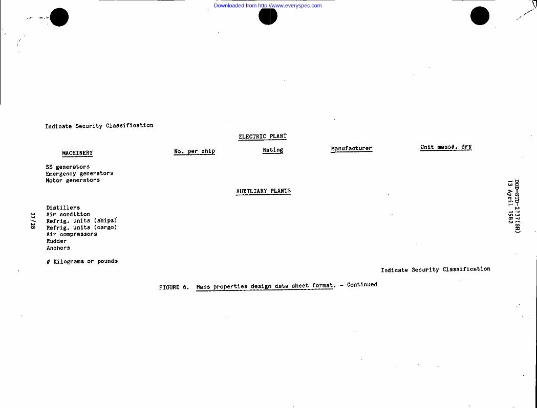
Mass properties design data sheet. The mass propertiesdesign data $heet shall contain the required information and shall be ofthe ~ormat indicated in figure 6 which” is an example of a steam poweredship. Major load and machinery items.as appropriate to the applicable shipshall be listed. This sheet shall include a note indicating whether theunits are in the S1 system or inch-pound system.
5.2.3.3 Mass distribution report. ‘A longitudinal mass distributionshall be develoued in a tabulated format in accordance with the standardlongitudinal st~tion breakdown (see 3.43). Mass and longitudinal center ofgravitys hall be determined for each ship station for both light ship andfull load condition. The resultant total mass and longitudinal center ofgravity for the mass distriliution report shall equal the values reflectedin the basic mass properties estimate or report for the same reportingperiod. ●
5.2.3.4 Input data cards. The input data c’ards provide inputs tothe Navy standard mass properties computer program. The card format shallbe as described in appendix A and shall reflect the same data used in thepreparation of the estimates or reports they accompany. These data may berIagnetiC tape in lieu of cards. Submittal by magnetic tape shall complywith the requirements set forth in ANSI X3.4.
5.2..3.5 Mass properties trade-off studies. Trade-off studies com-prise various engineering and technical studies directed toward determiningdetail mass properties data. These analytical studies are used to supportdesign change proposals and,to support recommendations for reversing trendstoward exceeding established margins or limits. These studies are con-ducted on an “as requested basis!!, and contain detailed mass propertiescalculations reflecting the impact of the study on ship displacement, KG,list and trim. There is no fixed format for the mass properties calcula-tions, but the SWBS classification system shall be used.
Preparing activity:Navy - SH(Project MISC-ND38)
20
Downloaded from http://www.everyspec.com

DOD-STD-2137(SH)
13
April
Ig~~
‘
r
.22
21
Downloaded from http://www.everyspec.com
DOD-STD-2137(SH)
1’3April
1’382
p
22
Downloaded from http://www.everyspec.com
Uil
DOD.STD-2
13
April23
37(SH)
982
—.
Downloaded from http://www.everyspec.com

———-—
.———
——
“DOD-STD-2137(SH)
13
April
1982
—— )(
——
u
24
Downloaded from http://www.everyspec.com

DOD-STD-2137(SH)
13
April
1982
io
IAEwPl
25
Downloaded from http://www.everyspec.com
.“DOD-sm-2137(SF)
13April1982’
.
26
Downloaded from http://www.everyspec.com
●O>.it,...—
MD-sTD-2137(SR)
..13April1982
27128
Downloaded from http://www.everyspec.com
,0
DOD-STD-2137(SH)13 April 1982
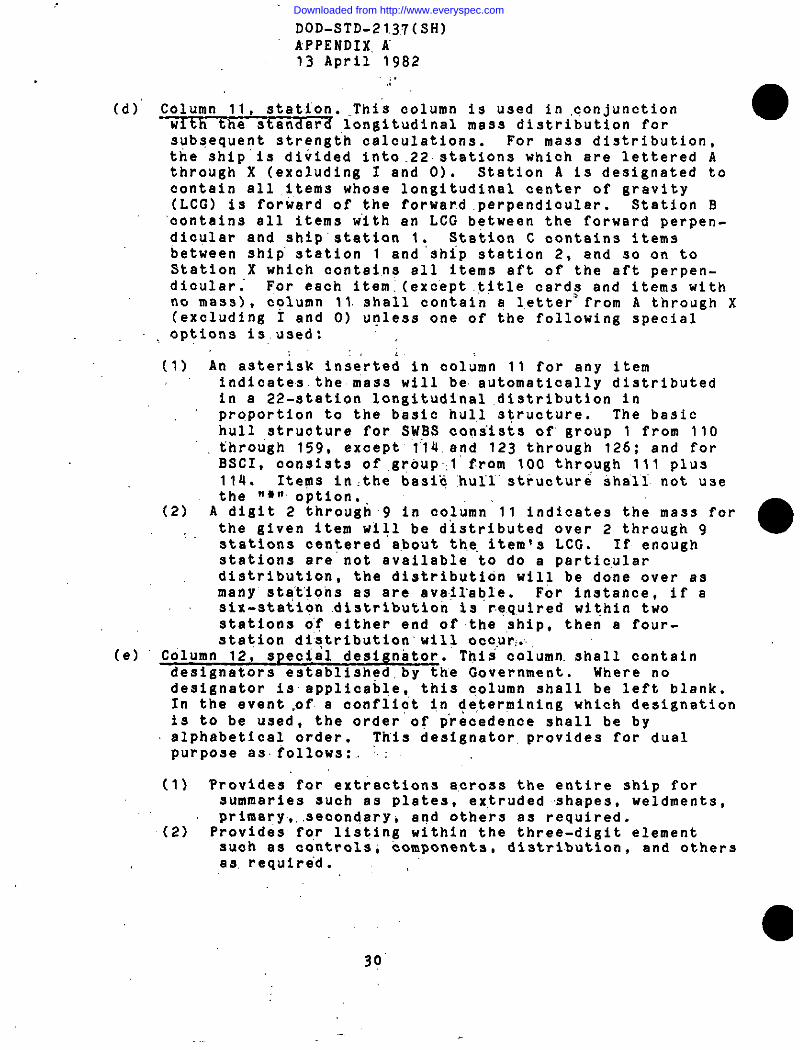
APPENDIx A
INPUT DATA CARD FORMAT
10. =. This appendix contains the required format forcompleting the standard Navy mass properties report input data cards.
20. Format Input data cards when required by the design contractor Ship Sp-;tions shall be interpreted and shall be punched in binarycoded decimal (BCD) in accordance with the format specified in thisappendix. The format is as follows:
(a) Columns 1 through 5, element numbers. Columns 1 through 3are based on the Ship Work Breakdown Structure (SWBS) (seeNAVSEA O9OO-LP-O39-9O1O) or Buraau of Ships ConsolidatedIndex (BSCI) of Drawings, Materials and Services Related toConstruction and Conversion (see NAVSEA 0902-LP-O02-2000).Colamns 4 and 5 provide for special subtotals within anelement number. Columns 4 and 5 shall contain only numericdata. Generally, two zeroes are used to designate a SWBSor BSCI element title. For example, Main Deck would bedesignated 13100 for SWBS or 10?00 for BSCI. It is noted,that SWBS subgroups ending in a zero are not to be used formass properties input data such as 110, 120, 230, 240, etc.
(b) Column 6. Column 6 is used for functional category desig-nation when required for nuclear powered ships. Thesecategories are defined by NAVSEA 0900-LP-039-9020 fOr SWBSand NAVSEA 0902-LP-O02-2000 for BSCI.
(c) ~ item number. The item number providesthe meana of identification of each line within any five-digit element number. The following rules apply:
(1)(2)
(3)
(4)
(5)
(6)
Each line shall have an item number.All title cards representing any of the basic SWBS orBSCI title shall include a ‘ZEROII in column 10.Note: Titles for special subtotals within a SWBSelement may contain any item number desired.
Care shall be taken not to repeat any item numberswithin a five-digit element.
Do not use any leading zeroes in the item number suchas 0010.Item numbers for entries should be entered in incre-ments of ten such as 10, 20, and 30 in lieu of 1, 2,and 3.
All item numbers shall be right justified.
29
I_
Downloaded from http://www.everyspec.com
DOD-STD-21.3:7(SH)APPENDIX, II13 April 1982
(d)’ Column 11, station. .,This column is used in ,conjunctionw~d longitudinal mass distribution forsubsequent strength c~lculations. For masa distribution,the ship’is divided into.22.etation$ which are lettered Athrough X (excluding I and O). Station A is designated tocontain all ,i,tems whose longitudinal center of gravity(LCG) is forward of the forwar.d,perpendicular. Station B‘contains all items w“ith an LCG between the forward perpen-dicular and ship’ etation 1: Station C contains itemsbetween ship’ station 1 and ship station 2, and so on toStation X which contains all Items aft of the aft perpen-dicular For each item, (except .tttle cards and items withno mass), column 11. shall contain q l,etter=from A through X(excluding I and O) unless one of the following specialoptiona is,used:
:’:(1) An asteriak inserted”in column 11 for any item
indicatesthemass will be automatically distributedin a 22-station longitudinal .dietribution inproportion to the basic hull structure. The basichull ,structure for SWBS consists of” group 1 from 110through 159, except” 1’14.and 123 through 126; and forBSCI, consists of,group,l from 100 through 111 plus114. Items In,the baaic “hul”l”structure shall. not usethe ‘*n option.
(2) A digit 2 through9 in column’11 indicates the mass forthe given item will be distributed over 2 through 9 ●stations centered about the, item~s LCG, If enoughstations are not available to do a particulardistribution, the distribution will be done over asmany” atq”t’ions ae are available. For instance, if asix-station .distribut.ion ia r.e.q,uiredwithin twostationa of either end of the ship, then a four-station distribution’will occur:..,
(e) Column 12, speciel designator. This’ column. shall containdesignators established. by the Government. Where nodesignator inapplicable,, this c,olumn shall be left blank.In the event ,of a conflict In determining which designationis to be used, the order of precedence shall be byalphabetical order. ~hls designator. provides for dualpurpose as. follows:.. .;
(1) ?rovides for extractions across the entire ship forsummaries such as plates, ex,truded shapes, weldments,primary,. ,secondary, and othera as required.
(2) Provides for listing within the three-digit elementsuch ae controls; components, distribution, and othersaa. require”d.
30’
Downloaded from http://www.everyspec.com
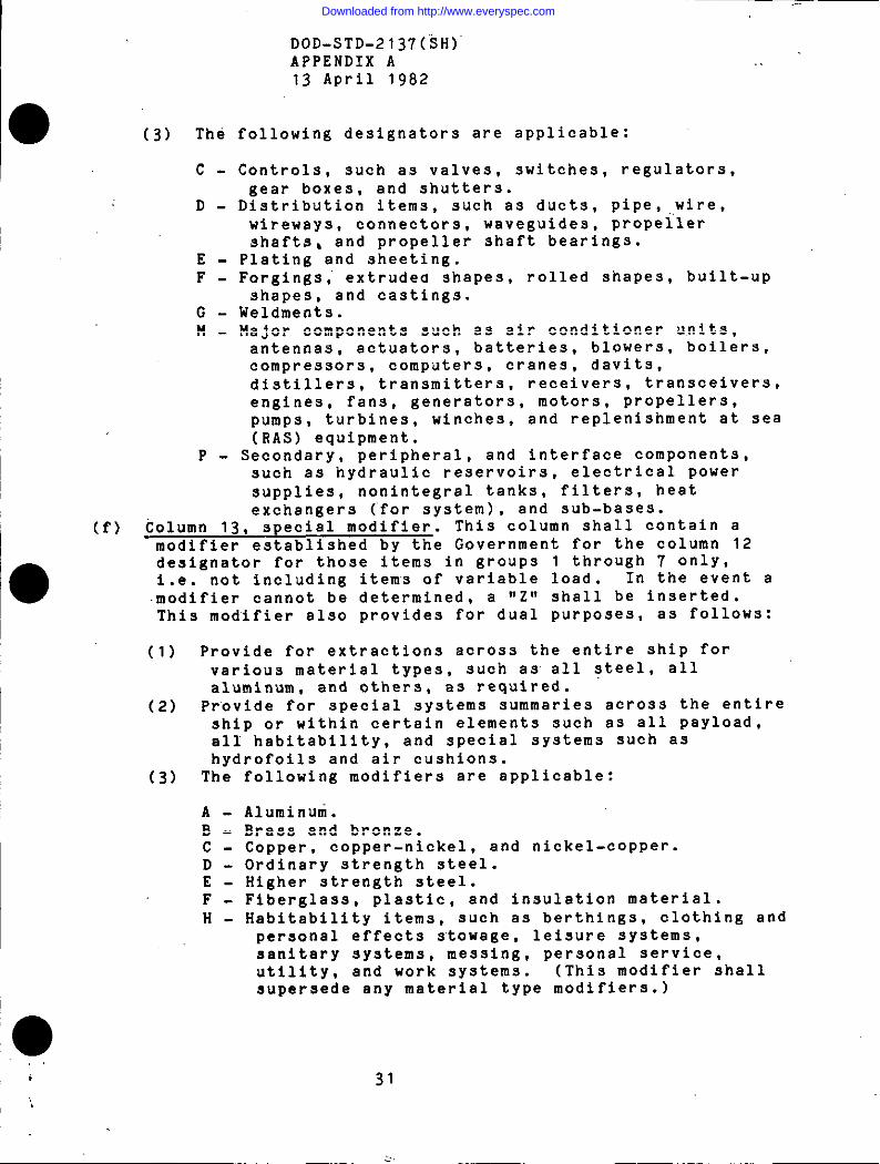
DOD-STD-2137(iH)APPENDIX A13 April 1982
0 (3) The
c-
D-
E-F-
G-M-
P-
following designatora are applicable:
Controls, such as valves, switches, regulators,gear boxes, and shutters.
Distribution items, such as ducts, pipe, ,,wire,wireways, connectors, waveguides, propellershafts, and propeller ahaft bearings.
Plating and sheeting.Forgings; extrudea shapes, rolled shapes, built-upshapes, and castings.
kleldmeota.Major components such as air conditioner units,antennas, actuators, batteries, blowers, boilers,compressors, computers, cranes, davits,distillers, transmitters, receivers, transceivers,engines, fans, generators, motors, propellers,pumps, turbines, winches, and replenishment at sea(RAS) equipment.
Secondary, DeriDheral, and interface COmPOnentS,such as-hydrauiic reservoirs, electrical powersupplies, nonintegral tanks, filters, heatexchangers (’for system), and sub-bases.
(f) Column 13, special modifier. This column shall contain amodifier established by the Government for the column 12designator for those i~ems in groups 1 through 7 only,i.e. not including items of variable load. In the event amodifier cannot be determined, a “z” shall be inserted.This modifier also provides for dual purposes, as follows:
(1) Provide for extractions across the entire ship for. .various material types, such as all steel, allaluminum, and others, as required.
(2) Provide for special systems summaries across the entireship or within certain elements such as all payload,all habitability, and special systems such ashydrofoils and air cushions.
(3) The
A-B-c-D-E-F-H-
0
following modifiers are applicable:
Aluminuni.Brass and bronze.Copper. copper-nickel, and nickel-copper.Ordinary strength steel.Higher strength steel.Fiberglass, plastic, and insulation material.Habitability items, such as berthings, clothing andpersonal effects stowage, leisure systems,sanitary systems, messing, personal service,utility, and work systems. (This modifier shallsuperseda any material type modifiers.)
31
2,
Downloaded from http://www.everyspec.com

J-K-.L -M-N-P-
W -,
DOD-STD-2137(SH)APPENDIX A13 April 1982
Wood material..Liquids. .“Lead.Miscellaneous metSllic material.Miscellaneous nonmetallic”material.Payload which includes items that are peculiar tothe specific missions of a particular shipi suchas minesweep gear, ‘on a mines~eeper, oceanographicgear on an oceanographic ship, etc. (Thismodifier shall supersede any material modifiers.)
Welding, riveting,, and fastening.
(g)’ Columns 14 tiirough 4.5,‘description. Use these 32 columnsto adequately describe each item. ‘Whatever is entered onthe input data card isrepro’duced exactly on the massproperties’ estimate or reportprintout. Any combination ofalpha-numeric characters or blanks can be used. Clear andcomplete description is essential.” Note: If budget massis b.eing.used,” see 20(h)” ofthis appendix, descriptionfield for “SWBS or BSCI element titles shall not extend pastcolumn 37.
(h) Columns 38 through 45, budge-t mas;. Budget mass, if used,is entered in integer kilograms- (.potinds)on SWBS or BSCItitle cards only. This allows mass” values- from O to
99,999,999 kilogram~ (pounds)”. (tobe entere@. 999999+99).(i) ~ Columns 46 through “53,”unit mass. Always en:er unit mass ●
of any item in kilograms “(pounds)~ The broken link on theStandard Navy Transmittal Form (NAVSEA 52.30/32) be.tw6encolumns 51 and 52 provides a decimal po}nt, .allOWing a Unit
mass UP to 999,999.99 “kilograms. (pounds). Whb,n’the unitmass is a whole number; enter zero,es be’hin’d’tliedecimalline in” columns 52 and 53. ‘If the mass i.s”’adeduction,enter a minus sign (-) immediately before’ t.he unit massnumber. ..
(j) Columns 54 through 57, number of units. Values from .001to 999 units can be entered. This number is multiplied byunit mass to produce total mass for each line item_. Unit-mass, number of units, and total mass are all printed inthe detail output. If a decimal riumb’dris”b’eing used innumber of units, the decimal point, must be punched.
(k) Columns 58 through 62, vertical cenfer of gravity (vCG).Use these columns for entering the .VCG.of each item, inmeters (feet) and hundredths. When the VCG is a wholenumber, enter zeroes behind the deci”mal line betweencolumns 60 and 61. (The VCG will, be”m~ltiplied by thecomputed total mass and the resultant vertical mass momentwill be printed. ) If the’ VCG.is negative (a mass below thebaseline), enter a minus (-) sign immediately before theVCG number.
32
Downloaded from http://www.everyspec.com
DOD-STD-2137(SH)APPENDIX A13 April 1982
-.
(1) C;~;l.;S 63 through 67, longitudinal center of gravity. Use these columns for entering the LCG of each
item, referenced in meters (feet) and hundredths forward oraft of the longitudinal reference datum. (The LCG will bemultiplied by the computed total mass and the resultantlongitudinal mass moment will be printed.) Always enter apositive LCG, no ,sign is necessary. When the LCG is awhole number, enter zeroes behind the decimal line betweencolumns 65 and 66.
(m) Column 68, LCG sign. As mentioned above, the LCG is alwaysentered as a positive value. Enter MF1’ or llA1tto indicatewhether the mass is located forward or aft of thelongitudinal reference datum. A blank in column 68 isinterpreted to mean “Att of aft.
(n) Columns 69 through 73 - Transverse center of gravity (TCG).Use these columns for antering the TCG of each item,referenced in meters (feet) and hundredths port orstarboard of the centerline. When the TCG is a wholenumber, enter a zero behind the decimal line betweencolumns 71 and 72. (The TCG will be multiplied by thetotal mass and the resultant transverse mass moment will beprinted. ) Always enter a positive TCG, no sign isnecessary. If the TCG is not applicable, leave columns 69through 73 blank.
(o) Column 74, TCG sign. As mentioned above, the TCG is alwaysentered as a positive value. Enter *1P*!or ~Sfl to indicatewhether the mass is port or starboard of the centerline. Ablank in column 7Q is interpreted to mean “P” or port.
(p) Column 75, reservation indicator (RES). This column isused to indicate mass reservation items or designresponsibility. The letter “R” shall be used to designatea reservation item. The letters ‘Avt through “Z” (exceptIIRII)may be used as required, to indicate design
responsibility such as:
H - Hull design.M - Machinery design.E - Electrical design.
(q) Column 76, reason for change. This column Is used toindicate reason for change as follows:
o - Nomenclature change (no mass properties change).1 - Contract modification change.2 - Government furnished material change.3- Change to class status such as estimated to calculated
or calculated to actual.4-9 and A-Z user assigned reasons.‘CHG’r in the output.
33
. .
The column appears under ......’.~.
i
Downloaded from http://www.everyspec.com

-.DOD-STD-21’37(SH)APPENDIX A13 April 1982
(r) Column 77, material, source indicator. The column is used o
to indicate the source of’an item as follows:
G- Government-furnished material.F- Contractor-fabricated material.P- Contractor-purchased material.
(s) Column 78, class ‘status. Us,e to indicate the confidence ofthe mass value entered for khe line item as follows:
E -.c-A.-v-
Estimated mass.,Calculated mass.Actual (scale) mass. ‘Vendor or catalog mass. (to be changed to “A” uPOn actualmass determination of the item.
(t) Columns 79 through 80, report” number. Enter the reportnumber where the than’ge was firs,t incorporated. Reportnumber ‘AO” shall be used for the first submittal of inputdata cards.. Cards changed prior to the first periodic massproperty report shall carry report number “BO” for thefirst such. change, ltcof!.f.or‘the secOnd, etc. The firstperiodic ma,ss properties report ‘shall have column 79 blankand 1*1!!in column 80, etc. Deletion cards shall containthe letters IIDDIIin columns 79’and “8o in lieu of a report
number .(u) General input data card requirements.
(1) Loadsa. Load title “cards. Title cards shall be prepared
for. each reauired load. condition and for each loadelement comprising that condition in accordancewith SWBS (this classification system isapplicable to BSCI loads also) in the followingformat:
Column 1 - Alpha load condition designator.Column 2-3 - Load element number.Column 4-5 - ZerOea.Column 10 -.Zero.Column 14 through37 - Load element title.
b. Load detail cards. Loads for SWBS and BSCI areclassified in much the same manner as light shipelements in groups 1-7 and follow the sameformat. Input data cards” must be prepared for alldetail ’load items comprising the full loadcondition (F in column 1). The letters A throughL are used in column 1 to indicate various otherloading conditions.
34
Downloaded from http://www.everyspec.com

DOD-STD-2137(SH)APPENDIX A13 April 1982
(2) Margins. Margins for SWBS and BSCI are classified inaccordance with SUBS. The mass and mass moment ofeach margin will be automatically distributed over the22 longitudinal stations in proportion to the lightship mass distribution. The margins can be either
input as a total mass, or as a percentage of totallit!ht shiD di9DlaCeIIIent. Marflin cards are DreDared ina ;imilar”mann~r to light shi~ details. Th~ firstcard of the margin group shall be a title card of theform ‘MOOOO----O ----Margins’t beginning on column 1.Margin depletions are handled as negative detail maasentries in the same manner as light ship details andfollow the same format. Margin options are asfollows:
a. Option 1 - input mass. Enter the total margin massin kil ograms (pounds) in columnS 46-53, andcenters of gravity as desired. All or any centerof gravity may be left blank. The margins willthen be automatically positioned at the light shipcenter of gravity.
b. Option 2 - percentages. Margin may be computed as
a percentage of total light ship. In the UNITMAsS. columns 46-53, enter the percentage desired(e.g.. 4 percent = 4.00). Enter zero in column57 of number of units. Center of gravity may beentered or left blank. If left blank, marginswill be placed at light’ ship center of gravity.
(3) Title cards. Seven title ~ards, one for each-of thegroups 1 through 7, are included in the Navy program.All other title cards shall be prepared by the user.It is required that a title card be prepared for eachof the SW13S or BSCI elements.
35/36
Downloaded from http://www.everyspec.com
DOD-STD-2137(SH)13 April 1982
APPENDIX B
DATA REQUIREMENTS
10. DATA
10.1 Data requirements. When this standard is used in a contractwhich incorporates a DD Form 1423 and invokes the provisions of 7-104.9(n)of the Defense Acquisition Regulation (DAR), the data requirementsidentified below will be developed as specified by an approved Data ItemDescription (DD Form 1664) and delivered in accordance with the approvedContract Data Requirements List (DD Form 1423) incorporated into thecontract. When the provisions of DAR 7’-lO4.9(n) are not invoked, the dataspecified below will be delivered by the contractor in accordance with thecontract requirements. Deliverable data required by this standard is citedin the following paragraphs:
I
Paragraph Data requirement Applicable DID—.
5.1 through 5.1.2.1, Bass properties estimates DI-E-21855.1.2.4 through and reports for surface5.1.2.8, 5.2 shipsthrough 5.2.3.5.fiizur~a 2 throu;h
●5,-and Appendix-A
5.1.2.2 Ship specifications UDI-E-26485section
5.1.2.3 Contract data require- DI-A-23434
ments list
(Copies of data item descriptions required by the contractorsconnection with specific acquisition functions should be obtained :
Option
------
------
------
inrom the
contracting activity or as directed by the contracting officer. )I
10.1.1 The data requirements of 10.1 and any task in the standardrequired to be performed to meet a data requirement may be waived by thecontracting/acquisition activity upon certification by the offeror thatidentical data were submitted by the offeror and accepted by the ’Governmefltunder a previous contract for identical item acquired to this standard.This does not apply to specific data which may be required for eachcontract, regardless of whether an identical item has been suppliedpreviously (for example, test reports).
,.
37
Downloaded from http://www.everyspec.com
●5TANDARDlZAT\ON DOCUMENT IMPROVEMENT PROPOSAL OMB APtWOVti
No. 22-R255
[NSTRUCTIONS ThepurpoSe.f fhiS form is to solicit beneficial comments which Will help mshleveprOc.re-ment of suitable vodu.ts at reasonable cost ●ndminirnum delby, or will otheryiseenhanceuseofthedocument.DOD c.niract.m, government activities. or manuf~etu=-lvemfors who ~MP~S ~uve WJpplie,s Of fhep= duct
1are invited to submit comments to the eovemmew. Fold 011lines 011-verse Si .e, ~tap:e ~ comer. and send topreparing activity. Comments mubmittedon this form do not constituteot imply ●uthotiaationfo wmive myportio. of the referenced document(s) .rto.am~d contractual re~irmrnts. Attsch ●IY perflnent data whichmay be of use im improving this document. If there am ●dditional papem, .tt.ch to form andplacekdb In anenvelope addressed to preparing activity.
oCUMENT IDENTIFIER AND TITLE
DOD-STD-2137(SH)AMEOFORGAN1ZATION ANDADDRE= CONTRACT NuMBER
MATCRIAL PROCURED UNOER A
001. Kc7.0vinNM*N7 c0NTR.cT 0SLi0c0N7RAC7
HAS ANY PART OF TMEOOCUMENT CREA7E0 PROOLEMSORREWIRE0 IN7ERPRE7A7,0NIN PROCUREMENT
-usE?
A. GtVE PA RAG RAPM NUMBER ANO WOROINO.. . ...> .. .
6. RECOM”ENOATf ONB FoR CORRSC71N0 THE DE FICISNCIKS
. . . . . . . . . . .,,,
,,‘: ,, \ $
..:,.’. ,
,. ..”,
,::. ‘-”
COMMENT$ON ANY DOCUMENT RSQUIR~MENT mN?$!=RCOTm RlOID
,. 1s THE WCUMENT RESTRICTIVE? .
I-J ,.. 0 .0 frf.,r..., fal$flti$wr?)
. REMARKS
UBMiTTED BY f%lnled a, tr#.d nm. d &&... - OPllon=f) TELEPHONC no.
0.47.%
1-- .... .. A- .,”.............vu ,;;;214zb RWPLACQ.SEOITION O* 1 JAN** WHICH MAY OCU~KB ““” ““”’-”’ --’---
.,, ...,.,,. ~ >....
Downloaded from http://www.everyspec.com