Embed Size (px)
Citation preview
7/25/2019 Mass Concrete Thermal Cracking Probability JCI
http://slidepdf.com/reader/full/mass-concrete-thermal-cracking-probability-jci 1/13
JCI GUIDELINES FOR
CONTROL OF CRACKING OF MASS CONCRETE 2008
Ryoichi SATO1, Shigeyuki SOGO
2,Tsutomu KANAZU
3, Toshiharu KISHI
4, Takafumi
NOGUCHI5, Toshiaki MIZOBUCHI
6 and Shingo MIYAZAWA
7
1 Hiroshima University, Japan
2 Hiroshima Institute of Technology, Japan
3 Central Research Institute of Electric Power Industry, Japan
4,5
The University of Tokyo, Japan6 Hosei University, Japan
7 Ashikaga Institute of Technology, Japan
1* 1-4-1, Kagamiyama, Higashi-Hiroshima, Hiroshima, 739-8527, [email protected]
2* 2-1-1 Miyake, Saeki-ku, Hiroshima-shi,Hiroshima, 731-5193, [email protected]
3* 1640 Abiko, Abiko-shi, Chiba, 270-1194, kanazu@criepi,denken.or.jp
4* 4-6-1 Komaba, Meguro-ku, Tokyo, [email protected]
5* 7-3-1 Hongo, Bunkyo-ku, Tokyo, [email protected]
6* 2-17-1 Fujimi, Chiyoda-ku, Tokyo, @[email protected]
7* 268-1 Omae-cho, Ashikaga-shi, Tochigi, 326-8558, [email protected]
ABSTRACT
Japan Concrete Institute revised “Guidelines for Control of Cracking of Mass Concrete” in
2008 after 20 years interval. The guidelines follow the same idea for control of cracking as
adopted in the original guidelines, and are composed corresponding to performance-based
verification system. The following technological contents developed for the revised
guidelines are incorporated; a relationship between thermal cracking index and thermal
cracking probability established based on the past construction examples, design values of
physical properties of concrete at early age applied to thermal stress analysis, an estimation
equation of thermal crack width including thermal cracking index, etc.
Keywords. mass concrete, performance based design, thermal cracking probability, thermal
cracking index, three dimensional finite element method
INTORODUCTION
Japan Concrete Institute revised “Guidelines for Control of Cracking of Mass Concrete” in
2008 after 20 years interval. The guidelines adopt a performance-based verification system
which was developed using information on the latest control and analysis technologies for
thermal cracking. The major aspects of the guidelines are:
(1) Basic principles of control of thermal cracking are clarified.
Third International Conference on Sustainable Construction Materials andTechnologies http://www.claisse.info/Proceedings.htm
7/25/2019 Mass Concrete Thermal Cracking Probability JCI
http://slidepdf.com/reader/full/mass-concrete-thermal-cracking-probability-jci 2/13
(2) By using 3D-FEM (three dimensional FEM) as a standard analysis technique, a new
diagram of thermal cracking probability relating to thermal cracking index is provided.
(3) By using the latest data, design values of concretes with different types of cement are
provided, incorporating the physical properties at early age.
(4) A simple equation for predicting crack width is provided, which uses the reinforcement
ratio as a parameter and the thermal cracking index.
(5) A simple equation for the thermal cracking index is provided.
In the guidelines, a “commentary” is added to provide details of the provisions. Reference
data that provide the grounds for the contents of the guidelines are also appended.
Furthermore, verification examples for thermal cracking are also appended, which are useful
as reference in the design process.
The outlines of JCI Guidelines are shown as follows.
CHAPTER 1 GENERAL
Scope. This document provides standard guidelines for design, construction and inspection
necessary to control thermal cracking due to heat of hydration of cement as well as
autogenous shrinkage in concrete structures.
In the commentary of chapter 1, the following important matters related to the scope are
described.
The guidelines provide methods to verify if thermal cracks develop, or whether thermal
cracks satisfy the limit value of crack width in the design stage for thermal crack control, and
if necessary, in the construction planning stage. Furthermore, the guidelines provide specific
procedures relating to design, materials, mixture proportions of concrete, construction to
control thermal cracking.
The provisions of the guidelines may be applicable to concrete structures whose concrete
characteristic compressive strength is below 60N/mm2 (60MPa), which are massive
unreinforced and reinforced concrete structures. The guidelines also apply to reinforced and
prestressed concrete structures that undergo large temperature drops from peak value as a
result of high cement content or high concrete temperatures during construction, even if the
structures are not massive in size. In general, mass concrete structures may be defined as
reinforced walls having thicknesses greater than 50 cm restrained at the base or slabs with
large surfaces having thicknesses greater than 80 cm.
The guidelines apply to mass concrete structures, and the period for verification of thermal
cracking is from the time of completion of concrete placement to the time when concrete
temperature equilibrates with the ambient temperature after the peak temperature. During
this period, the effect of drying shrinkage is negligible and consequently is neglected in the
verification procedure. Surface cracks, developed within one day after placing concrete due
to drying and temperature drop in surface layer and cracks, developed within several days
due to dominant internal restraint caused by a nonlinear distribution of temperature and
shrinkage, are not the target of the verification. This implies that surface cracking can be
avoided if construction, especially curing is conducted with appropriate care.
7/25/2019 Mass Concrete Thermal Cracking Probability JCI
http://slidepdf.com/reader/full/mass-concrete-thermal-cracking-probability-jci 3/13
Definition. The terms related to thermal cracking are defined for general use in the
guidelines.
Notation. The notations related to thermal cracking are explained for general use inthe guidelines.
CHAPTER 2 BASIS OF THERMAL CRACK CONTROL
Basic principle. The target of thermal crack control shall be set and achieved so as
to meet the performance requirements of the structures such as safety, serviceability,
durability and aesthetic.
Target of thermal crack control. The target of thermal crack control shall be either
the prevention of thermal cracking or the control of crack width. In the case of
preventing thermal cracking of concrete structures of which airtightness or water-
tightness should be secured only by the concrete material, thermal cracking
probability is a reference index for control and verification. In the case of allowingthermal cracking, crack width is a reference index for control and verification.Thermal cracks shall not exceed the limit values of the control target and verification
indices which are pre-defined based on the performance requirements and
environmental conditions.
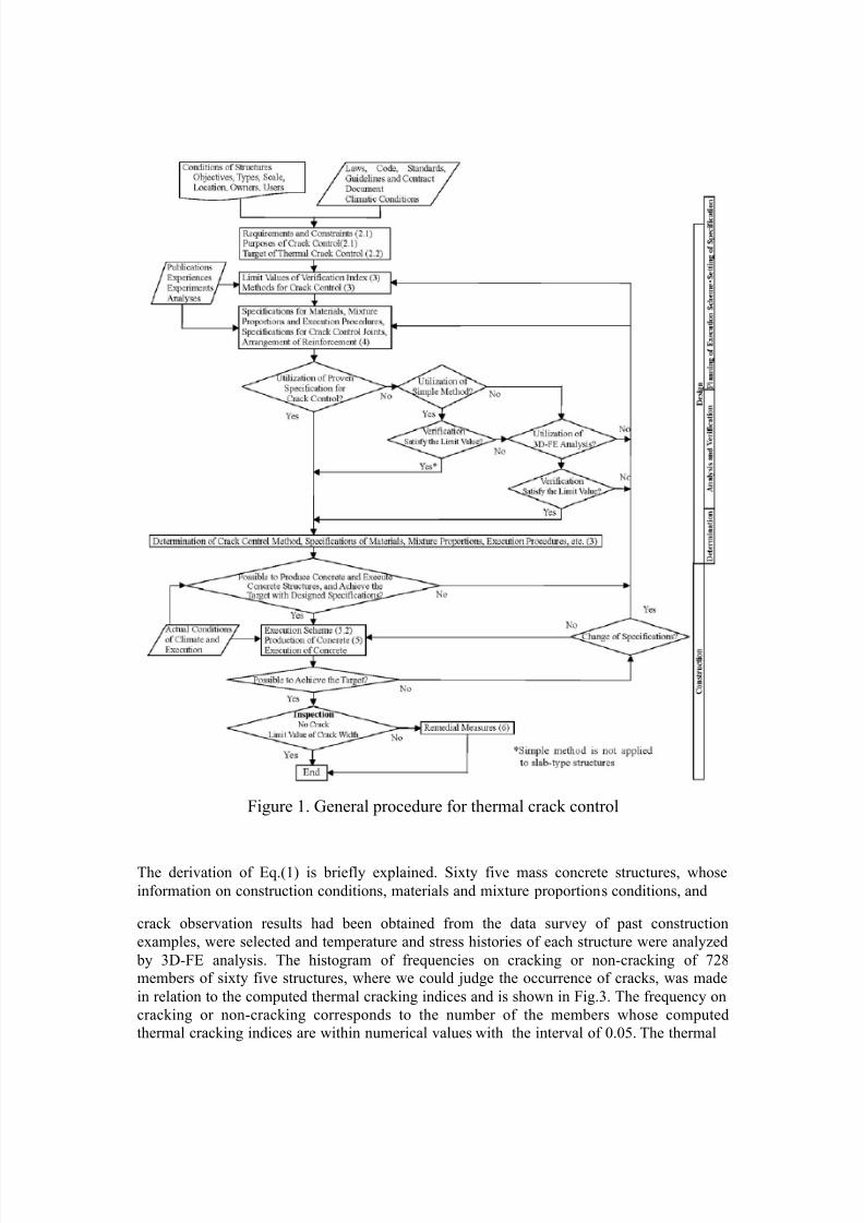
Control procedures. The control of thermal cracking shall be performed in thefollowing procedures as shown in Fig.1. At design stage, setting the control target
(Section 2.2), control planning (Chapter 3), analysis and verification (Chapter 4) anddetermination of the specifications (Chapter 4) are performed. Execution planning
(Chapter 5), quality control (Chapter 5) and inspection (Chapter 6) are conducted
before, during and after construction works, respectively. A flow chart of general procedure for control of thermal cracking is provided in the commentary.
CHAPTER 3 PLANNING FOR CONTROL OF THERMAL CRACKING
General. Proper plan shall be established to achieve control targets for thermal
cracking. Thermal crack control planning shall include specifications for crack
control joints and arrangement of reinforcing steel as well as specifications for
materials, mixture proportions and execution (placement time, placement
temperature limits, sequencing of concrete placements, curing method, etc.) taking
into account environmental conditions, structure type and construction conditions.
Limit values for control target. (1) Limit values for preventing thermal cracking. The limit value of thermalcracking probability shall be determined in consideration of performance
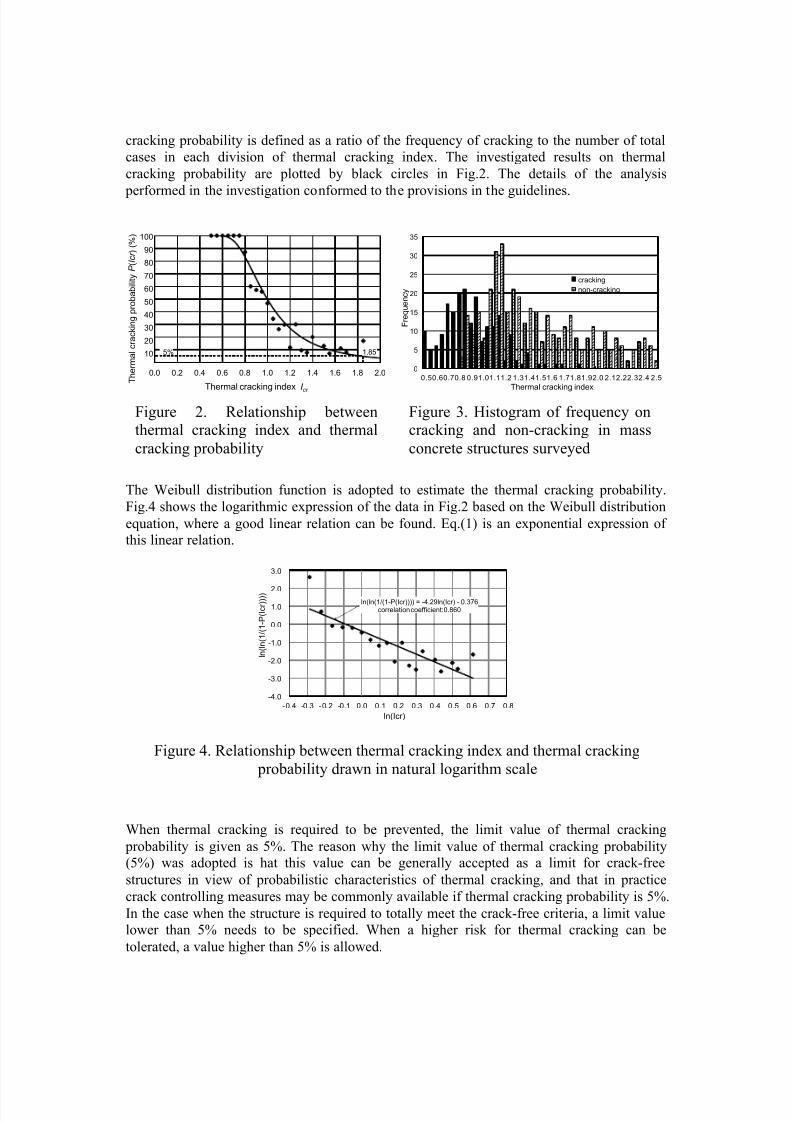
requirements and environmental conditions of the structures. A relationship betweenthermal cracking probability (P(Icr), %) and thermal cracking index (Icr; splitting
tensile strength/tensile stress) is derived as in the following equation (see Fig.2).
4.29
( ) 1 exp 1000.92
cr
cr
I P I
−⎡ ⎤⎛ ⎞= − − ×⎢ ⎥⎜ ⎟
⎝ ⎠⎢ ⎥⎣ ⎦ (1)
7/25/2019 Mass Concrete Thermal Cracking Probability JCI
http://slidepdf.com/reader/full/mass-concrete-thermal-cracking-probability-jci 4/13
Figure 1. General procedure for thermal crack control
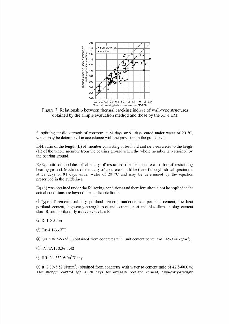
The derivation of Eq.(1) is briefly explained. Sixty five mass concrete structures, whose
information on construction conditions, materials and mixture proportions conditions, and
crack observation results had been obtained from the data survey of past construction
examples, were selected and temperature and stress histories of each structure were analyzed
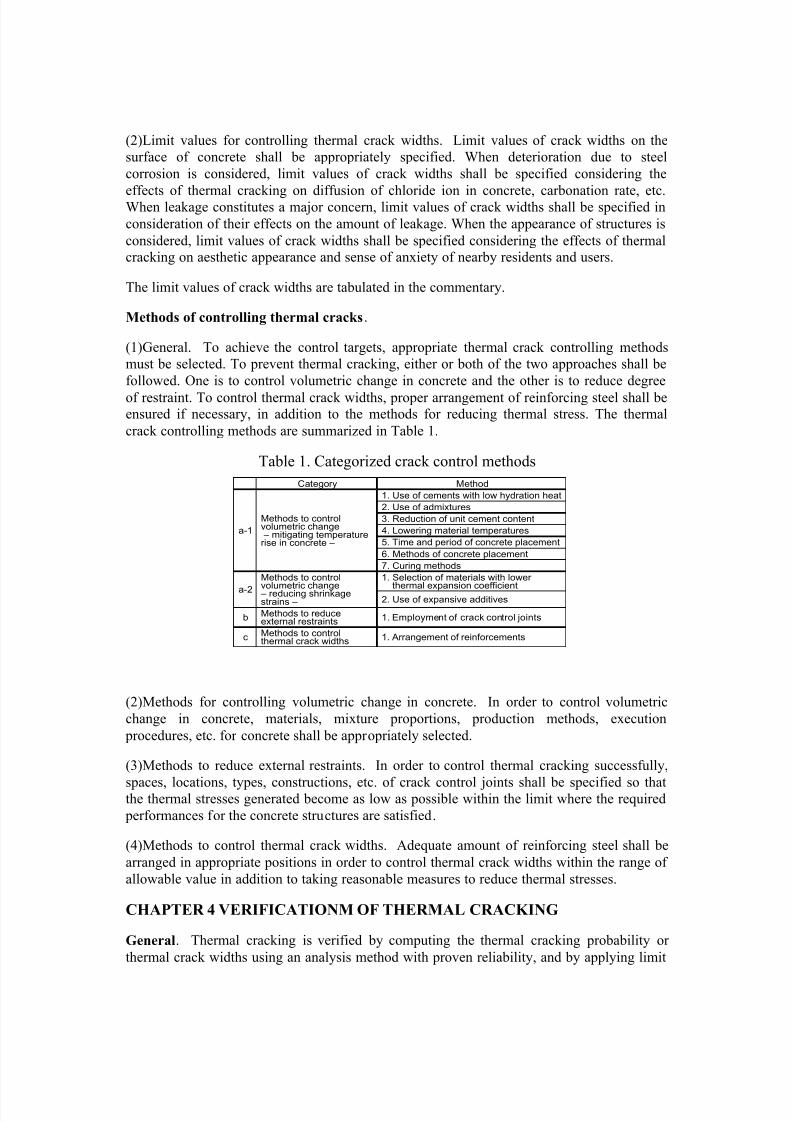
by 3D-FE analysis. The histogram of frequencies on cracking or non-cracking of 728
members of sixty five structures, where we could judge the occurrence of cracks, was made
in relation to the computed thermal cracking indices and is shown in Fig.3. The frequency on
cracking or non-cracking corresponds to the number of the members whose computed
thermal cracking indices are within numerical values with the interval of 0.05. The thermal
7/25/2019 Mass Concrete Thermal Cracking Probability JCI
http://slidepdf.com/reader/full/mass-concrete-thermal-cracking-probability-jci 5/13
cracking probability is defined as a ratio of the frequency of cracking to the number of total
cases in each division of thermal cracking index. The investigated results on thermal
cracking probability are plotted by black circles in Fig.2. The details of the analysis
performed in the investigation conformed to the provisions in the guidelines.
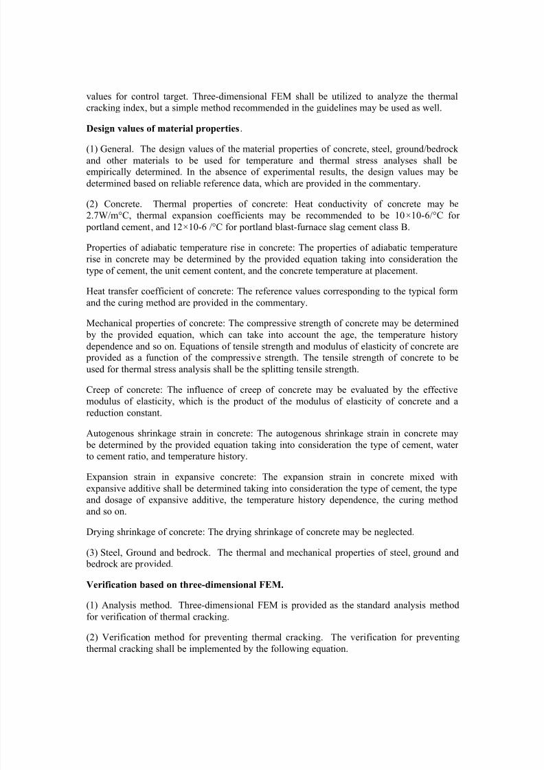
The Weibull distribution function is adopted to estimate the thermal cracking probability.
Fig.4 shows the logarithmic expression of the data in Fig.2 based on the Weibull distribution
equation, where a good linear relation can be found. Eq.(1) is an exponential expression of
this linear relation.
Figure 4. Relationship between thermal cracking index and thermal cracking
probability drawn in natural logarithm scale
When thermal cracking is required to be prevented, the limit value of thermal cracking
probability is given as 5%. The reason why the limit value of thermal cracking probability
(5%) was adopted is hat this value can be generally accepted as a limit for crack-free
structures in view of probabilistic characteristics of thermal cracking, and that in practice
crack controlling measures may be commonly available if thermal cracking probability is 5%.
In the case when the structure is required to totally meet the crack-free criteria, a limit value
lower than 5% needs to be specified. When a higher risk for thermal cracking can be
tolerated, a value higher than 5% is allowed.
0.0 0.2 0.4 0.6 0.8 1.0 1.2 1.4 1.6 1.8 2.0
Thermal cracking index I cr
100
90
80
70
60
50
40
30
20
10
T h e r m a l c r a c k i n g p r o b a b i l i t y P ( I c r ) ( % )
5% 1.85
0
5
10
15
20
25
30
35
0.50.60.70.8 0.91.01.11.2 1.31.41.51.6 1.71.81.92.0 2.12.22.32.4 2.5
F r e q u e n c y
Thermal cracking index
cracking
non-cracking
ln(ln(1/(1-P(Icr)))) = -4.29ln(Icr) - 0.376correlation coefficient:0.860
-4.0
-3.0
-2.0
-1.0
0.0
1.0
2.0
3.0
-0.4 -0.3 -0.2 -0.1 0.0 0.1 0.2 0.3 0.4 0.5 0.6 0.7 0.8
l n ( l n ( 1 / ( 1 - P ( I c r ) ) ) )
ln(Icr)
Figure 2. Relationship betweenthermal cracking index and thermal
cracking probability
Figure 3. Histogram of frequency oncracking and non-cracking in mass
concrete structures surveyed
7/25/2019 Mass Concrete Thermal Cracking Probability JCI
http://slidepdf.com/reader/full/mass-concrete-thermal-cracking-probability-jci 6/13
(2)Limit values for controlling thermal crack widths. Limit values of crack widths on the
surface of concrete shall be appropriately specified. When deterioration due to steel
corrosion is considered, limit values of crack widths shall be specified considering the
effects of thermal cracking on diffusion of chloride ion in concrete, carbonation rate, etc.When leakage constitutes a major concern, limit values of crack widths shall be specified in
consideration of their effects on the amount of leakage. When the appearance of structures is
considered, limit values of crack widths shall be specified considering the effects of thermal
cracking on aesthetic appearance and sense of anxiety of nearby residents and users.
The limit values of crack widths are tabulated in the commentary.
Methods of controlling thermal cracks.
(1)General. To achieve the control targets, appropriate thermal crack controlling methods
must be selected. To prevent thermal cracking, either or both of the two approaches shall be
followed. One is to control volumetric change in concrete and the other is to reduce degree
of restraint. To control thermal crack widths, proper arrangement of reinforcing steel shall beensured if necessary, in addition to the methods for reducing thermal stress. The thermal
crack controlling methods are summarized in Table 1.
Table 1. Categorized crack control methods
(2)Methods for controlling volumetric change in concrete. In order to control volumetric
change in concrete, materials, mixture proportions, production methods, execution
procedures, etc. for concrete shall be appropriately selected.
(3)Methods to reduce external restraints. In order to control thermal cracking successfully,
spaces, locations, types, constructions, etc. of crack control joints shall be specified so thatthe thermal stresses generated become as low as possible within the limit where the required
performances for the concrete structures are satisfied.
(4)Methods to control thermal crack widths. Adequate amount of reinforcing steel shall be
arranged in appropriate positions in order to control thermal crack widths within the range of
allowable value in addition to taking reasonable measures to reduce thermal stresses.
CHAPTER 4 VERIFICATIONM OF THERMAL CRACKING
General. Thermal cracking is verified by computing the thermal cracking probability or
thermal crack widths using an analysis method with proven reliability, and by applying limit
Category Method
a-1
Methods to controlvolumetric change – mitigating temperaturerise in concrete –
1. Use of cements with low hydration heat
2. Use of admixtures
3. Reduction of unit cement content
4. Lowering material temperatures
5. Time and period of concrete placement
6. Methods of concrete placement
7. Curing methods
a-2
Methods to control
volumetric change – reducing shrinkagestrains –
1. Selection of materials with lower
thermal expansion coefficient2. Use of expansive additives
b Methods to reduceexternal restraints 1. Employment of crack control joints
c Methods to controlthermal crack widths 1. Arrangement of reinforcements
7/25/2019 Mass Concrete Thermal Cracking Probability JCI
http://slidepdf.com/reader/full/mass-concrete-thermal-cracking-probability-jci 7/13
values for control target. Three-dimensional FEM shall be utilized to analyze the thermal
cracking index, but a simple method recommended in the guidelines may be used as well.
Design values of material properties.
(1) General. The design values of the material properties of concrete, steel, ground/bedrock
and other materials to be used for temperature and thermal stress analyses shall be
empirically determined. In the absence of experimental results, the design values may be
determined based on reliable reference data, which are provided in the commentary.
(2) Concrete. Thermal properties of concrete: Heat conductivity of concrete may be
2.7W/m°C, thermal expansion coefficients may be recommended to be 10×10-6/°C for
portland cement, and 12×10-6 /°C for portland blast-furnace slag cement class B.
Properties of adiabatic temperature rise in concrete: The properties of adiabatic temperature
rise in concrete may be determined by the provided equation taking into consideration the
type of cement, the unit cement content, and the concrete temperature at placement.
Heat transfer coefficient of concrete: The reference values corresponding to the typical form
and the curing method are provided in the commentary.
Mechanical properties of concrete: The compressive strength of concrete may be determined
by the provided equation, which can take into account the age, the temperature history
dependence and so on. Equations of tensile strength and modulus of elasticity of concrete are
provided as a function of the compressive strength. The tensile strength of concrete to be
used for thermal stress analysis shall be the splitting tensile strength.
Creep of concrete: The influence of creep of concrete may be evaluated by the effective
modulus of elasticity, which is the product of the modulus of elasticity of concrete and areduction constant.
Autogenous shrinkage strain in concrete: The autogenous shrinkage strain in concrete may
be determined by the provided equation taking into consideration the type of cement, water
to cement ratio, and temperature history.
Expansion strain in expansive concrete: The expansion strain in concrete mixed with
expansive additive shall be determined taking into consideration the type of cement, the type
and dosage of expansive additive, the temperature history dependence, the curing method
and so on.
Drying shrinkage of concrete: The drying shrinkage of concrete may be neglected.
(3) Steel, Ground and bedrock. The thermal and mechanical properties of steel, ground and
bedrock are provided.
Verification based on three-dimensional FEM.
(1) Analysis method. Three-dimensional FEM is provided as the standard analysis method
for verification of thermal cracking.
(2) Verification method for preventing thermal cracking. The verification for preventing
thermal cracking shall be implemented by the following equation.
7/25/2019 Mass Concrete Thermal Cracking Probability JCI
http://slidepdf.com/reader/full/mass-concrete-thermal-cracking-probability-jci 8/13
(2)
where, Pt: limit value of the thermal cracking probability, to be regarded as 5 %, Pc: thermalcracking probability obtained by the provided method (%).
In practice, however, based on Fig.2 the thermal cracking index which is equivalent to
thermal cracking probability is applicable to the verification. In this case the limit value can
be assumed as 1.85.
(3) Verification method for controlling thermal crack widths. The verification for
controlling the thermal crack widths is implemented by the following equations.
(3)
where, wa: limit value of crack width (mm), wc; thermal crack width obtained by the
following equation (mm), γi: safety factor for verification, generally allowed to be 1.0.
(4)
where, p: reinforcement ratio (%, the ratio of the reinforcement area perpendicular to the
crack direction to the intended concrete area), the applicable range of which is 0.25 % to
0.93 %. Icr: thermal cracking index, the applicable range of which is not more than 1.85. γa:
safety factor to evaluate the thermal crack widths, which shall be 1.0 to 1.7 depending on the
performance requirements.
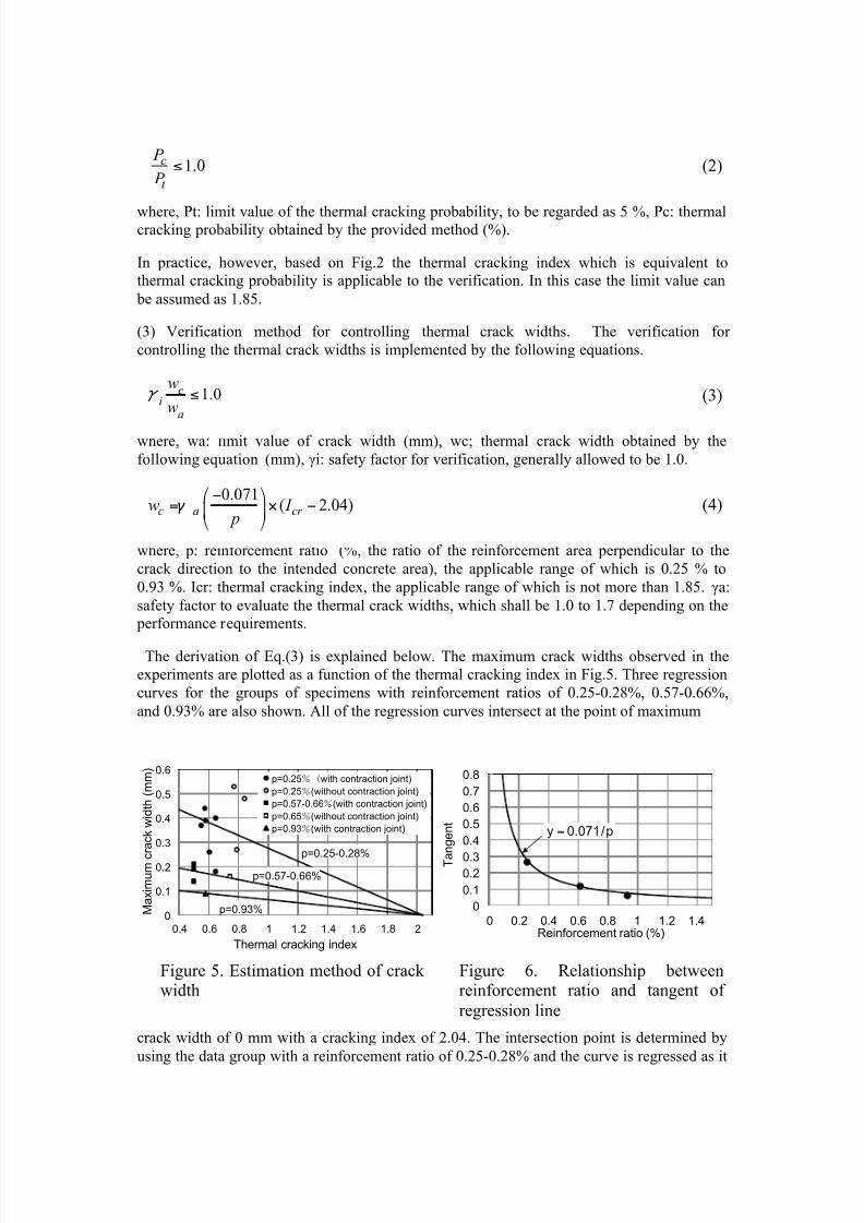
The derivation of Eq.(3) is explained below. The maximum crack widths observed in the
experiments are plotted as a function of the thermal cracking index in Fig.5. Three regression
curves for the groups of specimens with reinforcement ratios of 0.25-0.28%, 0.57-0.66%,
and 0.93% are also shown. All of the regression curves intersect at the point of maximum
crack width of 0 mm with a cracking index of 2.04. The intersection point is determined by
using the data group with a reinforcement ratio of 0.25-0.28% and the curve is regressed as it
0
0.1
0.2
0.3
0.4
0.5
0.6
0.4 0.6 0.8 1 1.2 1.4 1.6 1.8 2
M a x i m u m c
r a c k w i d t h ( m m )
Thermal cracking index
p=0.25with contraction joint)
p=0.25(without contraction joint)
p=0.57-0.66(with contraction joint)
p=0.65(without contraction joint)
p=0.93(with contraction joint)
p=0.25-0.28%
p=0.93%
p=0.57-0.66%
0
0.1
0.20.3
0.4
0.5
0.6
0.7
0.8
0 0.2 0.4 0.6 0.8 1 1.2 1.4Reinforcement ratio (%)
T a
n g e n t
=y 0.071/p
Figure 5. Estimation method of crackwidth
Figure 6. Relationship betweenreinforcement ratio and tangent of
regression line
1.0c
t
P
P ≤
i
wc
wa
≤1.0
0.071( 2.04)c a cr w I
p
⎛ ⎞−= × −⎜ ⎟
⎝ ⎠
7/25/2019 Mass Concrete Thermal Cracking Probability JCI
http://slidepdf.com/reader/full/mass-concrete-thermal-cracking-probability-jci 9/13
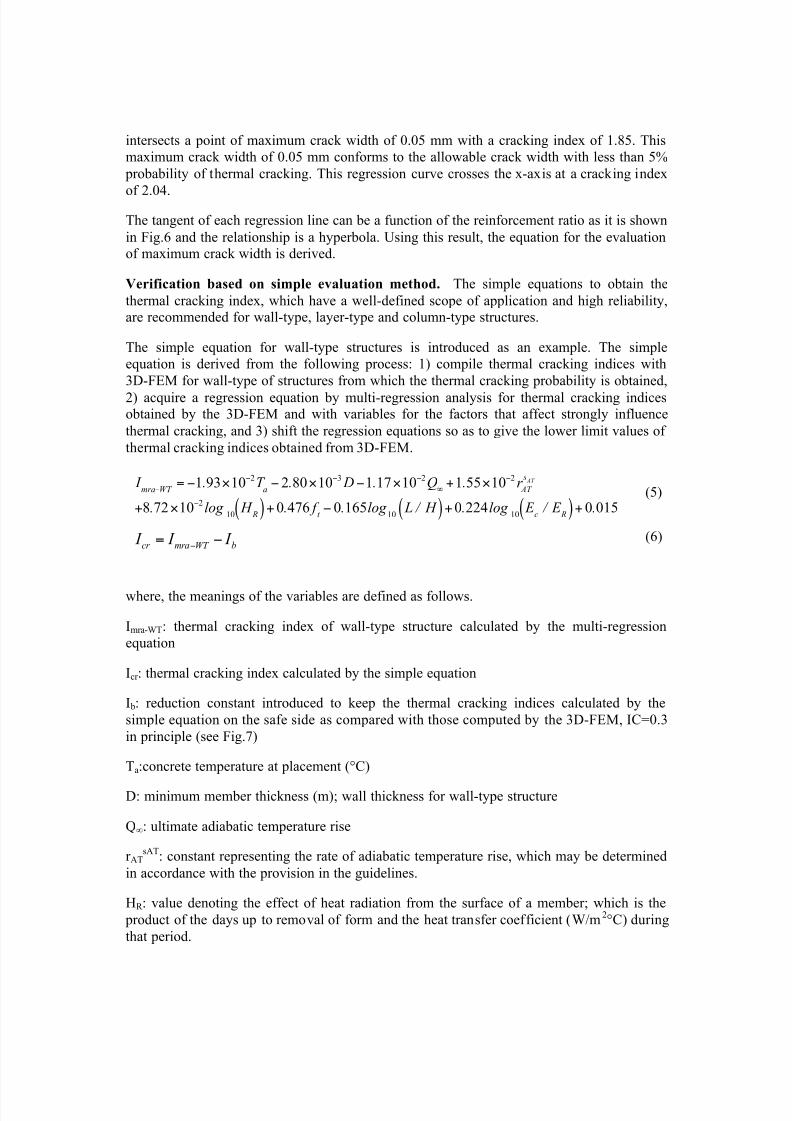
intersects a point of maximum crack width of 0.05 mm with a cracking index of 1.85. This
maximum crack width of 0.05 mm conforms to the allowable crack width with less than 5%
probability of thermal cracking. This regression curve crosses the x-axis at a cracking index
of 2.04.
The tangent of each regression line can be a function of the reinforcement ratio as it is shown
in Fig.6 and the relationship is a hyperbola. Using this result, the equation for the evaluation
of maximum crack width is derived.
Verification based on simple evaluation method. The simple equations to obtain the
thermal cracking index, which have a well-defined scope of application and high reliability,
are recommended for wall-type, layer-type and column-type structures.
The simple equation for wall-type structures is introduced as an example. The simple
equation is derived from the following process: 1) compile thermal cracking indices with
3D-FEM for wall-type of structures from which the thermal cracking probability is obtained,
2) acquire a regression equation by multi-regression analysis for thermal cracking indicesobtained by the 3D-FEM and with variables for the factors that affect strongly influence
thermal cracking, and 3) shift the regression equations so as to give the lower limit values of
thermal cracking indices obtained from 3D-FEM.
(5)
(6)
where, the meanings of the variables are defined as follows.
Imra-WT: thermal cracking index of wall-type structure calculated by the multi-regression
equation
Icr : thermal cracking index calculated by the simple equation
I b: reduction constant introduced to keep the thermal cracking indices calculated by the
simple equation on the safe side as compared with those computed by the 3D-FEM, IC=0.3
in principle (see Fig.7)
Ta:concrete temperature at placement (°C)
D: minimum member thickness (m); wall thickness for wall-type structure
Q∞: ultimate adiabatic temperature rise
r ATsAT
: constant representing the rate of adiabatic temperature rise, which may be determined
in accordance with the provision in the guidelines.
HR : value denoting the effect of heat radiation from the surface of a member; which is the
product of the days up to removal of form and the heat transfer coefficient (W/m2°C) during
that period.
I mra−WT
= −1.93×10⁻²T a− 2.80×10
−3 D−1.17×10
−2Q∞+1.55×10
−2r AT
s AT
+8.72×10⁻² log
10 H
R( )+0.476 f t − 0.165log
10 L / H ( )+0.224log
10 E
c / E
R( )+0.015
cr mra WT b I I I
−
= −
7/25/2019 Mass Concrete Thermal Cracking Probability JCI
http://slidepdf.com/reader/full/mass-concrete-thermal-cracking-probability-jci 10/13
Figure 7. Relationship between thermal cracking indices of wall-type structures
obtained by the simple evaluation method and those by the 3D-FEM
f t: splitting tensile strength of concrete at 28 days or 91 days cured under water of 20 °C,
which may be determined in accordance with the provision in the guidelines.
L/H: ratio of the length (L) of member consisting of both old and new concretes to the height
(H) of the whole member from the bearing ground when the whole member is restrained by
the bearing ground.
Ec/ER : ratio of modulus of elasticity of restrained member concrete to that of restraining
bearing ground. Modulus of elasticity of concrete should be that of the cylindrical specimensat 28 days or 91 days under water of 20
oC and may be determined by the equation
prescribed in the guidelines.
Eq.(6) was obtained under the following conditions and therefore should not be applied if the
actual conditions are beyond the applicable limits.
Type of cement: ordinary portland cement, moderate-heat portland cement, low-heat
portland cement, high-early-strength portland cement, portland blast-furnace slag cement
class B, and portland fly ash cement class B
D: 1.0-5.4m
Ta: 4.1-33.7oC
Q: 38.5-53.9oC, (obtained from concretes with unit cement content of 245-324 kg/m3)
rATsAT: 0.36-1.42
HR: 24-232 W/m2o
Cday
ft: 2.39-3.52 N/mm2, (obtained from concretes with water to cement ratio of 42.8-60.0%)
The strength control age is 28 days for ordinary portland cement, high-early-strength
0.0
0.2
0.4
0.6
0.8
1.0
1.2
1.4
1.6
1.8
2.0
0.0 0.2 0.4 0.6 0.8 1.0 1.2 1.4 1.6 1.8 2.0
T h e r m a l c r a c k i n g i n d e x o b t a i n e d b y
m u l t i - r e g r e s s i o n e q u a t i o n
non-cracking
cracking
Thermal cracking index computed by 3D-FEM
7/25/2019 Mass Concrete Thermal Cracking Probability JCI
http://slidepdf.com/reader/full/mass-concrete-thermal-cracking-probability-jci 11/13
portland cement, and portland blast-furnace slag cement class B, and 91 days for moderate-
heat portland cement, low-heat portland cement and portland fly ash cement class B.
L/H: 0.4-30 (L: 3.0-40m, H: 0.75-7.2m)
Ec/ER: greater than 7
CHAPTER 5 CONSTRUCTION WORKS
General. The important items to be observed relating to plan and implementation for both
execution and quality control are provided. The principles related to execution and quality
control to achieve the control target of a mass concrete structure and those implementation
procedures are prescribed. An emergency action for an obstacle due to unexpected matters
that will lead to difficulties of the achievement of control target in the stages of execution is
provided to be taken. The information obtained through execution and quality control shall be recorded and kept to judge the execution quality as well as to make a rational control plan
for a similar execution in future.
Execution plan and quality control plan. Construction documents and quality control
documents shall be compiled and the execution plan shall include standards for measures
against unexpected rapid climate changes beyond assumptions during execution.
Implementation of execution.
(1) General. The general principles for implementation of execution are provided.
Subsequently, the principles for the following each item necessary for mass concrete
construction are provided.
(2) Crack control joint. Methods to induce a crack at the planned section and materials to
assure water tightness and durability for steel corrosion are introduced.
(3)Production of concrete. Control of a temperature of fresh concrete is regarded as
important.
(4) Ready- mixed concrete. Ready-mixed concrete adapted to JIS A 5308 is applied to mass
concrete construction in principle.
(5) Transportation, placing and compaction of concrete. Control of temperature during
transportation, and uniformity between upper and lower concrete layers during placing and
compaction are regarded as important.
(6) Construction joint. It is necessary to consider that the surface areas of vertical and
horizontal construction joints are very large.
(7) Curing. Proper materials for curing and measures for excessive weather change should
be selected.
(8) Pipe curing. Water leakage from pipe and breakage of pipe must be prevented, and
effective control method of circulating water should be adopted.
(9) Selection of forms. Proper form materials should be selected.
7/25/2019 Mass Concrete Thermal Cracking Probability JCI
http://slidepdf.com/reader/full/mass-concrete-thermal-cracking-probability-jci 12/13
Implementation of quality control.
(1) General. The general principles for implementation of quality control are provided.
Subsequently, the principles for the following each item necessary for the quality control are
provided
(2) Control by measurement. Placing temperature of concrete and temperature history of
placed concrete must be controlled below the values determined in control plan.
(3) Control at placing concrete. Rate of concrete placement, sequence of placing, and time
interval of overlaying concrete should be managed.
(4) Control of curing. Curing in accordance with execution plan must be implemented, time
at form removal should be properly judged, and effective measures for unexpected measured
results should be taken.
(5) Control of structure. Realization of planed quality of mass concrete structure must beconfirmed.
CHAPTER 6 INSPECTION
Inspection must be done to confirm whether a control target for thermal cracking determined
in the stage of control pan is achieved or not after construction.
General. The general principles of inspection are provided for inspector, timing and method
of inspection, judgment criteria, and countermeasures for rejection of inspection.
Inspection methods. The principles of inspection method are provided for inspection targetrelating to a control target, timing of inspection, and precision necessary for measuring crack
widths.
Judgment of inspection results and countermeasures. The principles are provided for
indices and their criteria to judge the achievement of control target, elucidation of the
cracking causes and the subsequent countermeasures in case of rejection.
Recording of inspection results. Recording of inspection results as well as subsequent
countermeasures is provided to utilize them for the maintenance management of the structure.
APPENDICES
Appendix A. Standards for various types of cement, which are specified in Japan, USA and
EU, are summarized. Qualities of typical cements in Japan, which coincide with those of
cement assumed for determining the design values of adiabatic temperature, are shown in
comparison with the specified values in the standard. Standards for blast-furnace slag and
fly ash specified in Japan and other countries are also summarized.
Appendix B (Reference materials). Reference materials are provided in order to give
detail information from which articles in the guidelines were derived. The reference
materials include the following items.
(1) Derivation of relationship between thermal cracking index and thermal cracking
probability by three-dimensional finite element method
7/25/2019 Mass Concrete Thermal Cracking Probability JCI
http://slidepdf.com/reader/full/mass-concrete-thermal-cracking-probability-jci 13/13
(2) Derivation of simple evaluation equation for thermal cracking index
(3) Thermal cracking control tests of reinforced concrete wall structures subjected to
continuous restraint at the bottom
(4) Relationship between thermal cracking index and maximum crack width
(5) Expansion strain of expansive concrete
(6) Simple method for thermal crack control of RC box culvert with crack control joint
(7) An investigation on thermal crack control of internal restraint predominant structure
(8) Estimation of representative values for adiabatic temperature rise
Appendix C (Case studies). In case studies, two examples of verification for thermal
cracking of a box culvert and a pier-type structure are provided. The verification was carried
out in accordance with the guidelines.
CONCLUDING REMARKS
JCI guidelines are applicable to mass concrete structures in any country if the design values
of concrete produced are determined in a similar way to the guidelines in accordance with
the physical and thermal properties and the characteristics of materials in each country.
Japan Concrete Institute hopes that the guidelines will be widely applied to mass concrete
constructions in foreign countries.
The committee activities will be continued to revise the technological contents in the
guidelines and to improve the practical use.
ACKNOWLEDGEMENT
The authors acknowledge the cooperation of the members of the technical committees on
“English Version of JCI Guidelines for Control of Cracking of Mass Concrete” and
“Revision of JCI Guidelines for Control of Cracking of Mass Concrete”.
This paper is a reprint of the paper published in Proceedings of the 3rd JCI-KCI-TCI
Symposium held at Hiroshima in July 1st-3rd, 2012. The permission of reprint from the
organizing committee chaired by Prof. Hirozo Mihashi is greatly appreciated.
REFERENCES
Japan Concrete Institute (2011): “Guidelines for control of cracking of mass concrete 2008”