Embed Size (px)
Citation preview
Joumal of Research of the National Bureau of Standards Volume 90, Number 4, July-August 1985
Mass Comparator for In-Situ Calibration of Large Mass Standards
R. M. Schoonover National Bureau of Standards, Gaithershurg, MD 20899
Accepted: July 17, 1985
This paper describes a high precision electronic mass comparator with a range from 250 kg to 5,000 kg. It is suggested that it would be useful to transport the comparator to the test weights rather than to transport the weights to the comparator, the usual method, thus economizing time and monies.
Key words: constant load; electronic; large weights; load cell; mass; mass comparator; portable; tolerance testing.
Introduction
In many laboratories around the world there are large dead weight testing machines used for calibrating strain gage load cells, proving rings, and other force transducers. Usually a special balance or scale for reverification of the dead-weight mass values is available should the need arise. If not, then on occasion the machine may have to be disassembled and transported to a laboratory where appropriate mass standards and weighing machines exist.
In the United States, and probably in most countries represented at the 1985 mass seminar of the International Measurement Confederation, the transportation oflarge mass standards, weighing many thousands of kilograms, is a daily occurrence. Usually these mass standards are in the nature of scale test weights for which the user does not need a mass value which is accurate to a few parts per million, but must only be
About the Author: R. M. Schoonover is with the Length and Mass Division in the NBS Center for Basic Standards.
289
assured that his weights are within a specified tolerance to meet the legal requirements for commerce. The tolerance placed on these test weights is approximately I part in 10,000. The following discussion describes a new portable electronic mass comparator. This unit can easily be transported, along with a suitable mass standard, to any site where reasonable weighing conditions exist, allowing relatively rapid and inexpensive verification of a collection of weights.
The Mass Comparator
Although the mass comparator is described well in the literature [1,2,3,4j1 a brief description of the unit and how it operates will be useful for those not familiar with the principles.
First, as the name implies, the device is either a mass comparator or a force comparator. Since the local acceleration of gravity affects equally the mass standard and the test weight, the masses can be compared directly (assuming the displacement volumes are equal). This comparison could be made on any strain gage load cell.
I Figures in brackets indicate literature references.
However, since the resulting measurement may not be accurate to within 1 part in 10,000, one could not state with assurance whether the measured test weight is in or out of tolerance.
Because a load cell has the desirable features of portability, electric signal output, small size, and the possibility of battery operation, it would be highly useful if the following disadvantages could be overcome:
I) Hysteresis 2) Creep 3) Sensitivity to Off-axis loading 4) Sensitivity to torque loading 5) Unbalanced bridge self-heating 6) Sensitivity to barometric pressure variatIOns.
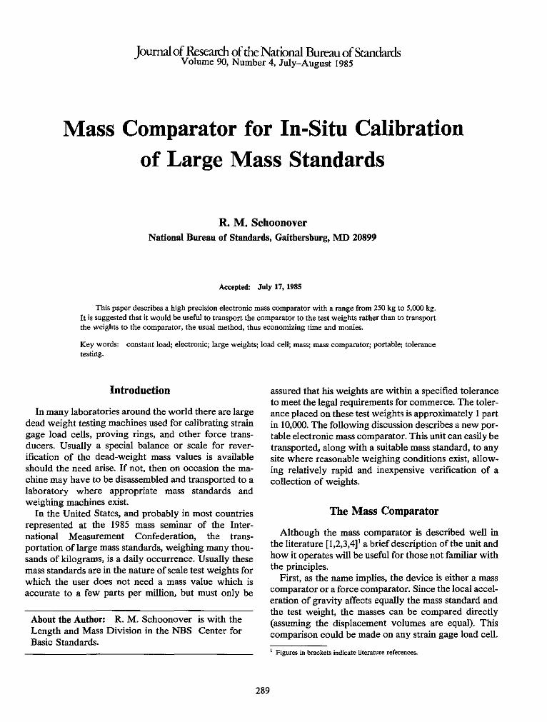
The first two items on the list, hysteresis and creep, are circumvented by the most important principle of the mass comparator, which is a constant loading of the load cell at all times, even during the period when the mass standard and the test weight are being exchanged. This is accomplished with a servomechanism [I] that uses coiled springs in tension to supply the force required to automatically maintain a constant load on the cell even when the equivalent mass load is in the process of changing. Figure I demonstrates this principle.
The next two items on the list, sensitivity to off-axis loading and sensitivity to torque loading, can be eliminated by the placement of high-quality universal joints above and below the cell and a good-quality, robust
z e le :::E
t
thrust bearing at the load connecting point. These serve to keep the load axially aligned through the cell and eliminate torque that might otherwise be imparted to the cell during loading and unloading of the weights.
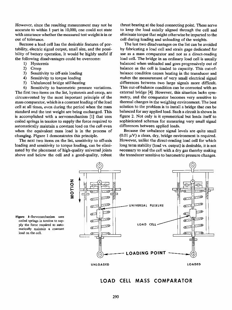
The last two disadvantages on the list can be avoided by fabricating a load cell and strain gage dedicated for use as a mass comparator and not as a direct-reading load cell. The bridge in an ordinary load cell is usually balanced when unloaded and goes progressively out of balance as the cell is loaded to capacity. This out-ofbalance condition causes heating in the transducer and makes the measurement of very small electrical signal differences between two large signals more difficult. This out-of-balance condition can be corrected with an external bridge [4]. However, this situation lacks symmetry, and the comparator becomes very sensitive to thermal changes in the weighing environment. The best solution to the problem is to install a bridge that can be balanced for any applied load. Such a circuit is shown in figure 2. Not only is it symmetrical but lends itself to sophisticated schemes for measuring very small signal differences between applied loads.
Because the unbalance signal levels are quite small (0.01 Jk V) a clean, dry, bridge environment is required. However, unlike the direct-reading load cell for which long term stability (load vs. output) is desirable, it is not necessary to seal the cell with a dry gas thereby making the transducer sensitive to barometric pressure changes.
+
EE-=ilm{:;:::=-+f--- UN I V E R SAL HE X U R E
Figure l-Servomechanism uses coiled springs in tension to supply the force required to automatically maintain a constant load on the cell.
LOAD CELL
+ '>-_-- LOADING POINT
UNLOADED LOADED
LOAD CELL MASS COMPARATOR
290
r------,
~ I I
Balancing - Low Noise - Phase
I I I I I I I I
y ~ Network Amplifier Detection
I I I
Load Cell I L ____ ..J
L- AC Strip Chart Computer
Data
Integrator
Digital
Figure 2-A symmetrical bridge that can be balanced for any applied load.
L....- Bridge Recorder Acquisition Readout Excitation (Optional) (Optional)
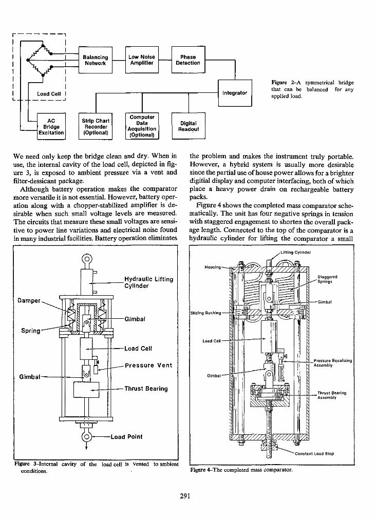
We need only keep the bridge clean and dry. When in use, the internal cavity of the load cell, depicted in figure 3, is exposed to ambient pressure via a vent and filter-dessicant package.
Although battery operation makes the comparator more versatile it is not essential. However, battery operation along with a chopper-stabilized amplifier is desirable when such small voltage levels are measured. The circuits that measure these small voltages are sensitive to power line variations and electrical noise found in many industrial facilities. Battery operation eliminates
o
+ ____ Hydraulic Lifting Cylinder
Damper
I..,;'~~tt--Gimbal
4--+f--Load Cell
--,-..-_Pressure Vent
Gimba'--li-;::±:L..,
_f--H--Thrust Bearing
)---Load Point
Figure 3-Internal cavity of the load cell is vented to ambient conditions.
the problem and makes the instrument truly portable. However, a hybrid system is usually more desirable since the partial use of house power allows for a brighter digitiaI display and computer interfacing, both of which place a heavy power drain on rechargeable battery packs.
Figure 4 shows the completed mass comparator schematically. The unit has four negative springs in tension with staggered engagement to shorten the overall package length. Connected to the top of the comparator is a hydraulic cylinder for lifting the comparator a small
Cylinder
Load C,II -+*H-7t---j-
ill'-Hl-i:\-~:~::~~~~", Equalizing
---""m","' Load Stop
Figure 4-The completed mass comparator.
291
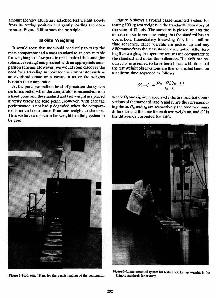
amount thereby lifting any attached test weight slowly from its resting position and gently loading the comparator. Figure 5 illustrates the principle.
In-Situ Weighing
It would seem that we would need only to carry the mass comparator and a mass standard to an area suitable for weighing to a few parts in one hundred thousand (for tolerance testing) and proceed with an appropriate comparison scheme. However, we would soon discover the need for a traveling support for the comparator such as an overhead crane or a means to move the weights beneath the comparator.
At the parts-per-million level of precision the system performs better when the comparator is suspended from a fIXed point and the standard and test weight are placed directly below the load point. However, with care the performance is not badly degraded when the comparator is moved on a crane from one weight to the next. Thus we have a choice in the weight handling system to be used.
Figure 5-Hydraulic lifting for the gentle loading of the comparator.
Figure 6 shows a typical crane-mounted system for testing 500 kg test weights in the standards laboratory of the state of Illinois. The standard is picked up and the indicator is set to zero, assuming that the standard has no correction. Immediately following this, in a uniform time sequence, other weights are picked up and any differences from the mass standard are noted. After testing five weights, the operator returns the comparator to the standard and notes the indication. If a drift has occurred it is assumed to have been linear with time and the test weight observations are then corrected based on a uniform time sequence as follows:
where O. and ON are respectively the first and last observations ofthe standard, and I. and IN are the corresponding times. Ox; and Ix; are respectively the observed mass difference and the time for each test weighing, and O~ is the difference corrected for drift.
Figure 6-Crane-mounted system for testing 500 kg test weights in the Illinois standards laboratory.
292
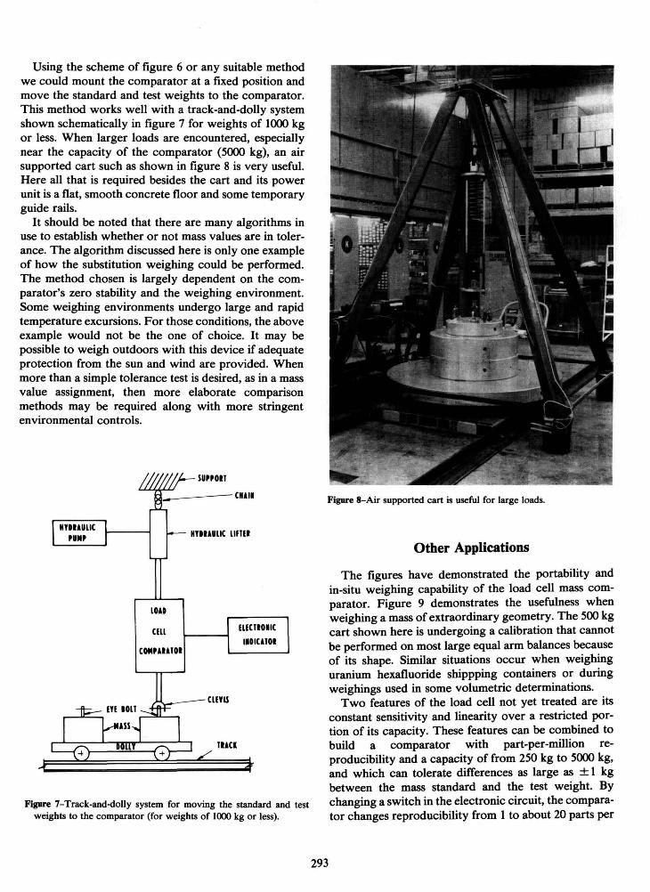
Using the scheme of figure 6 or any suitable method we could mount the comparator at a fixed position and move the standard and test weights to the comparator. This method works well with a track-and-dolly system shown schematically in figure 7 for weights of 1000 kg or less. When larger loads are encountered, especially near the capacity of the comparator (5000 kg), an air supported cart such as shown in figure 8 is very useful. Here all that is required besides the cart and its power unit is a flat, smooth concrete floor and some temporary guide rails.
It should be noted that there are many algorithms in use to establish whether or not mass values are in tolerance. The algorithm discussed here is only one example of how the substitution weighing could be performed. The method chosen is largely dependent on the comparator's zero stability and the weighing environment. Some weighing environments undergo large and rapid temperature excursions. For those conditions, the above example would not be the one of choice. It may be possible to weigh outdoors with this device if adequate protection from the sun and wind are provided. When more than a simple tolerance test is desired, as in a mass value assignment, then more elaborate comparison methods may be required along with more stringent environmental controls.
SUPPOIT
_ ----C""I
lOU
cm COICPAUTOI
"YlUUlIC lIflll
CUYU
TUU
mCTIOIIC
I •• ICATOI
Figure 7-Track-and-dolly system for moving the standard and test weights to the comparator (for weights of 1000 kg or less).
Figure 8-Air supported cart is useful for large loads.
293
Other Applications
The figures have demonstrated the portability and in-situ weighing capability of the load cell mass comparator. Figure 9 demonstrates the usefulness when weighing a mass of extraordinary geometry. The 500 kg cart shown here is undergoing a calibration that cannot be performed on most large equal arm balances because of its shape. Similar situations occur when weighing uranium hexafluoride shippping containers or during weighings used in some volumetric determinations.
Two features of the load cell not yet treated are its constant sensitivity and linearity over a restricted portion of its capacity. These features can be combined to build a comparator with part-per-million reproducibility and a capacity of from 250 kg to 5000 kg, and which can tolerate differences as large as ± I kg between the mass standard and the test weight. By changing a switch in the electronic circuit, the comparator changes reproducibility from I to about 20 parts per
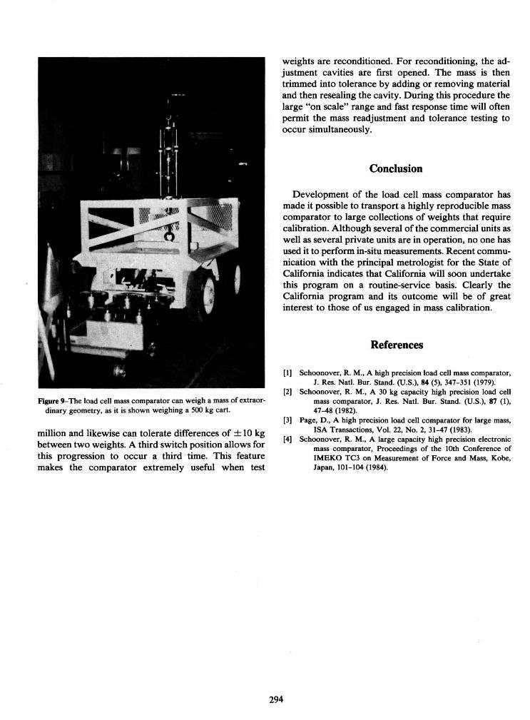
Figure 9-The load cell mass comparator can weigh a mass of extraordinary geometry, as it is shown weighing a 500 kg cart.
million and likewise can tolerate differences of ± 10 kg between two weights. A third switch position allows for this progression to occur a third time. This feature makes the comparator extremely useful when test
weights are reconditioned. For reconditioning, the adjustment cavities are first opened. The mass is then trimmed into tolerance by adding or removing material and then resealing the cavity. During this procedure the large "on scale" range and fast response time will often permit the mass readjustment and tolerance testing to occur simultaneously.
Conclusion
Development of the load cell mass comparator has made it possible to transport a highly reproducible mass comparator to large collections of weights that require calibration. Although several of the commercial units as well as several private units are in operation, no one has used it to perform in-situ measurements. Recent communication with the principal metrologist for the State of California indicates that California will soon undertake this program on a routine-service basis. Clearly the California program and its outcome will be of great interest to those of us engaged in mass calibration.
294
References
[I] Schoonover, R. M., A high precision load cell mass comparator, J . Res. Natl. Bur. Stand. (U.S.), 84 (5), 347-351 (1979).
[2] Schoonover, R. M., A 30 kg capacity high precision load cell mass comparator, J . Res. Natl. Bur. Stand. (U.S.), 87 (1), 47-48 (1982).
[3] Page, D., A high precision load cell comparator for large mass, ISA Transactions, Vol. 22, No.2, 31-47 (1983).
[4] Schoonover, R. M., A large capacity high precision electronic mass comparator, Proceedings of the 10th Conference of IMEKO TC3 on Measurement of Force and Mass, Kobe, Japan, 101-104 (1984).