Embed Size (px)
Citation preview

J. Basic. Appl. Sci. Res., 2(2)1395-1406, 2012
© 2012, TextRoad Publication
ISSN 2090-4304 Journal of Basic and Applied
Scientific Research www.textroad.com
*Corresponding Author: Mostafa mahmoodi, Faculty of Mechanical Engineering, K. N. Toosi University of Technology, Tehran, Iran. P.O.Box: 1999-19395. Email: [email protected].
Numerical Solution of Beta-type Stirling Engine by Optimizing Heat Regenerator for Increasing Output Power and Efficiency
Masoud Ziabasharhagh1 Mostafa Mahmoodi2
1 Associate professor, Faculty of Mechanical Engineering, K. N. Toosi University of Technology, Tehran, Iran. 2 Ph.D. candidate, Faculty of Mechanical Engineering, K. N. Toosi University of Technology, Tehran, Iran.
ABSTRACT In this paper, an appropriate thermodynamic model was developed for the beta-type Stirling engine. This model is capable of predicting and optimizing the output power and operational parameters of the Stirling engine based on the geographical and physical conditions of all its components. To this end, the numerical solution of the beta-type Stirling engine was conducted by the five-volume method and using the adiabatic model. To confirm the obtained results, the operational and geographical specifications of the Stirling engine made in the General Motors Corporation were used and the obtained results were compared with the published results. These results showed the increase in the energy absorption by the regenerator in high operational pressure and bigger length-to-diameter ratio of the regenerator. Moreover, considering the achieved results, an optimum point can be determined for the length of the regenerator in order to reach the most efficiency and highest output power. KEY WORDS: Striling engine, Numerical solution, Adiabatic model, Regenerator.
Nomenclature
A Area, m2 Greek symbols Cp specific heat at constant pressure, J/(kg K) γ Ideal gas specific heat ratio Cv specific heat at constant volume, J/(kg K) θ Crank rotational angle, radians
D diameter, m Subscripts dm wire diameter, m c Compression space e Eccentricity, m ck Interface between compression space and cooler L Connecting rod length, m cl Clearance space in engine M mass of working gas in the engine, kg e Expansion space m mass of gas in different components, kg h Heater P Pressure, Pascal he Interface between heater and expansion space Q Heat, J k Cooler r Connecting rod length, mm kr Interface between cooler and regenerator R gas constant, J/(kg K) r Regenerator
T Temperature, K rh Interface between regenerator and heater
1. INTRODUCTION Many attempts are being made all over the world in order to make power-generator engines with
appropriate efficiency and with the capability of using waste heat recovery and renewable energy sources at the same level as the fossil fuels. Increase of energy cost and environmental and noise pollutions have led to more serious studies on the new power generation engines. Use of non-renewable energy sources of the earth including petroleum, gas and coal destroys the societies’ public wealth and produces one-fourth of the total carbon dioxide of the world. Stirling engine is one of the ideas which have attracted the attention of many interested researchers in recent years. In physical terms, the Stirling engine is an external combustion engine and can use any kinds of external heat sources (waste heat from industrial machinery, combustion and solar energy) for producing mechanical energy. Recently, researchers have reached good results in designing and using Stirling engines. Stirling technology development for making solar engines which generate the axial power of 10 KW is one of the most important achievements. Also, the combined heat and power (CHP) generation plan is one of the new ideas which have been commercialized by the generation companies of this technology and are used in power generation bases. At present, new methods of using Stirling methods are studied which include application of Stirling engines for
1395

Ziabasharhagh and mahmoodi, 2012
providing the required power for satellites and using Stirling engines as an alternative for the steam turbines of nuclear power plants.
Many studies have been done on Stirling engines since their invention by Robert Stirling. The first mathematical analysis which was acceptable for analyzing Stirling cycle was presented by Schmidt fifty years after its invention [1]. Schmidt’s analysis was done based on the theories of isotherm compression chamber and isotherm expansion chamber. Using the Schmidt’s assumption, the thermodynamic equations were linear and the initial calculations were easily done for measuring the engine’s output efficiency and power. Today, Schmidt’s analysis is widely used for the initial analysis of Stirling engines. Schmidt’s cycle assumes expansion and compression processes as isotherm processes. However, in practice, this assumption is not true for the engines with 1000 rpm or more engine cycles since, as proved by Rankin, heating or cooling does not occur exactly at the constant temperature or constant volume and expansion and compression processes of the cylinders of the Stirling engine are closer to the adiabatic. Therefore, more appropriate assumptions should be used for thermodynamic modelling in order to get closer to the actual efficiency of the engine by these models.
If attempts for modelling Stirling engines are not within the isotherm solution, the equations will not be clear and can only be solved differentially and using numerical methods. In the adiabatic cycle, heat efficiency is turned to a function which depends not only on temperature but also on swept volume ratio, phase angle and dead volume ratio. In fact, the output power is a function of all the mentioned parameters either in the isotherm or adiabatic cycles. In 1975, Finkelstein [2] improved Schmidt’s thermodynamic analysis and presented the initial adiabatic analyses. While solving equations in the adiabatic way, compression chamber and expansion chamber are considered adiabatic. Considering the adiabatic assumption, the equations become non-linear and numerical methods should be used for solving them. Since the Finkelstein model was presented, the conducted analyses have been done based on different thermodynamic models (isotherm and adiabatic), use of different heat sources (heat waste, solar and combustion) and different forms of Stirling engine (gamma-, beta- and alpha-type engines); the studies done by Urieli and Berchowitz [3] which used the adiabatic thermodynamic model for obtaining the Stirling engine’s output efficiency and power can be referred to. Kongtragool and Wongwises [4] conducted the Stirling engine’s modelling and optimization using the isotherm model and Timoumi al. [5, 6 and 7] investigated its losses and irreversibility using the Stirling engine’s adiabatic modelling. In recent studies done by Tlili et al.[8, 9], the Stirling engine was modelled using the solar energy as the heat source. Thombare and, Verma [10] gathered the available technologies and obtained achievements with regard to the analysis of Stirling engines and, at the end, presented some suggestions for their applications. Furthermore, Alireza Tavakkolpour et al. [11] analyzed the gamma-type Stirling engine using the Schmidt’s theory, solving the equations in the isotherm way and using flat panels for absorbing solar heat as the hot temperature source. After modelling the Stirling engine, Invernizzi [12] investigated the effect of using different gasses on the engines’ output power and efficiency. Formosa and Despesse [13] conducted the modelling by means of the isotherm model in order to investigate the effects of dead volumes on the engine’s output power and efficiency.
In the present study, the thermodynamic relations of all the engine components were applied, the numerical code written in the Matlab software was used and, as a result, the beta-type Stirling engine was modelled in the five-volume method using the adiabatic thermodynamic model. To increase the accuracy of simulation, actual relations were used for the changes of volume of the pistons inside the cylinders and no simplification was used in this regard. At the end, the obtained results were compared with the results presented for the engine made by General Motors Corporation (GPU-3), which geometrical and operational specifications are present. The obtained results showed that energy flow was very important for heat regenerator and its optimized design can prevent the waste of a large amount of the received energy from the high-temperature heat source during the engine work cycle. Finally, the effects of different geometrical and physical conditions of heat regenerator on the engine’s output power and efficiency were studies and the optimized values were suggested. 2. Thermodynamic Modelling
The Stirling engine works in a closed thermodynamic cycle and converts thermal energy to mechanical motion. Considering the physical structure of this engine, it has five main subsystems; each subsystem is considered a control volume in modelling. There are two spaces with variable volumes which are called expansion space and compression space and there are three heat exchanger with the constant volume which are called heater, cooler and regenerator (Figure 1). Moreover, the engine has a drift mechanism which controls volume changes during the work cycle and transfers the alternating linear motion of pistons as the angular momentum to the driving shaft. Different types of the Stirling engine are identified by the names alpha, beta and gamma. All of them are similar in terms of thermodynamic cycle; however, there are fundamental differences as far as mechanical mechanisms are concerned. Alpha-type Stirling engine has two pistons in two separate cylinders. A heater is built in one cylinder and a cooler in
1396

J. Basic. Appl. Sci. Res., 2(2)1395-1406, 2012
4 Heater
3
Regenerator
2
Cooler 1
another cylinder. The operating gas starts its going and coming movement from the heater and enters the cooler by the regenerator. In the beta-type Stirling engine, there are two pistons inside one cylinder which are called displacer piston and power piston. The displacement piston moves the operating fluid between the cold space and hot space through the heater, cooler and regenerator and leads to the movement of the power piston (Figure 2). The gamma-type Stirling engine is a combination of alpha and beta types. In theoretical terms, the efficiency of the Stirling engine is equal to the efficiency of the Carnot cycle. The transferred heat from the operating gas to the regenerator during the 4 to 1 process is absorbed by the operating gas during the 2 to 3 process. A source for heat sink and another source for heat source are required to be used during the 1 to 2 and 3 to 4 processes (Figure 1).
Figure 1: The components of Stirling engine and the operation of their cycle
Figure 2: Beta-type Stirling engine
Heat regenerator is probably the most impotent component of the Stirling engine which has a fundamental role in increasing its efficiency. As far as the physical structure is concerned, the heat regenerator is made of stainless steel as mesh sheets or stainless steel rods which are stacked (Figure 3). During the half of the engine’s work cycle, the heat regenerator acts like a sponge and leads to heat absorption from the operating cycle. In another half of the cycle, the regenerator returns the heat to the operating gas; therefore, there is less amount of heat in the cold area of the engine for dissipation, which leads to the increase of engine efficiency. Thus, the use of the regenerator in the Stirling engine decreases the heat waste and, finally, increases the engine efficiency.
Compression space
Power piston
Displacer piston
Cooler
Heater
Expansion space
Regenerator
Carter
Rod
Crank
1397

Ziabasharhagh and mahmoodi, 2012
c
c
c
VTmp
ck
ck
Tm
k
k
k
VTm
kr
kr
Tm
r
r
r
VTm
rh
rh
Tm
he
he
Tm
h
h
h
VTm
c
c
c
VTm
WW
kQ hQ
e
e
e
VTm
Figure 3: The structure of heat regenerator The modeling conducted in this paper was for the beta-type engine using the five-volume method. In this method, the components of the Stirling engine were divided to five separate sections and thermodynamic equations were extracted for each unit. Then, appropriate boundary conditions were considered for the movement of the fluid flow inside the components of the engine at the interfaces between cells. Finally, the numerically obtained equations were solved using the method mentioned below. Figure 4 shows the schematic model and the distribution of different temperatures at different parts of the engine.
Figure 5 demonstrates the rate of volume change using the motion mechanism and its obtained relations. Reliable input specifications are required for testing the capabilities of the conducted modeling.
Figure 4: The five-volume model for simulating the Stirling engine
Figure 5: Operation mechanism and volume changes in the beta-type Stirling engine To this end, exact specifications of the engine made by General Motors Corporation
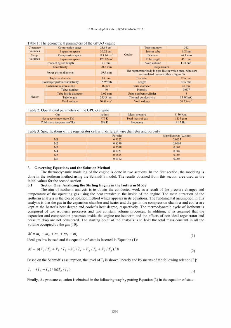
(Ground Power Unit-3) were used; in addition to its physical and geometrical characteristics, its operational specifications are available, which have been used by many scholars for modeling validation. In Table 1, the engine’s geometrical parameters including the exact geometrical specifications and the swept volume by the power piston and displacement piston, looseness amount of the power piston and displacement piston, geometrical characteristics and the number of pipes of heat exchangers are given. In Table 2, the engine’s operational specifications including the operating gas, temperature of cold and hot areas, average pressure of the operating fluid, mass of gas and motion frequency of the engine are mentioned. Table 3 presents the specifications of the regenerator cell with porosity and wires with different diameters in order to observe the engine’s output power and efficiency variation compared with their changes. Other input parameters required for the analysis based on the engine’s conditions and form were calculated using the available equations during the numerical solution.
r
cV
eV
bL
e
Lb
ey
cy
py
dy maxdy
b
)cosre(sinrAddV pc
2
cosrAA
AddV
ddV
dp
dc
e
2
222 erLb
22 reLb
221 reLb
223 reLb
)sinrbb(AVV dclee 2
)bb(AVV pclcc 12
1398
J. Basic. Appl. Sci. Res., 2(2)1395-1406, 2012
Table 1: The geometrical parameters of the GPU-3 engine Clearance volumes
Compression space 28.68 cm3
Cooler
Tubes number 312 Expansion space 30.52 cm3 Interns tube 1.08mm
Swept volumes
Compression space 113.14 cm3 Diameter 46.1 mm Expansion space 120.82cm3 Tube length 46.1mm
Connecting rod length 46 mm Void volume 13.8 cm3 Eccentricity 20.8 mm Regenerator
Power piston diameter 69.9 mm The regenerator body is pipe-like in which metal wires are accumulated on each other (Figure 3)
Displacer diameter 69 mm Diameter 22.6 mm Exchanger piston conductivity 15 W/mK Length 22.6 mm
Exchanger piston stroke 46 mm Wire diameter 40 mµ
Heater
Tubes number 40 Porosity 0.697 Tube inside diameter 3.02 mm Units numbers/cylinder 8
Tube length 245.3 mm Thermal conductivity 15 W/mK Void volume 70.88 cm3 Void volume 50.55 cm3
Table 2: Operational parameters of the GPU-3 engine
Kpa 4130 Mean pressure helium Gas grm 1.135 Total mass of gas 977 K Hot space temperature(Th) Hz 41.7 Frequency 288 K Cold space temperature(Tk)
Table 3: Specifications of the regenerator cell with different wire diameter and porosity
Porosity Wire diameter (dm) mm M1 0.9122 0.0035 M2 0.8359 0.0065 M3 0.7508 0.007 M4 0.7221 0.007 M5 0.6655 0.008 M6 0.6112 0.008
3. Governing Equations and the Solution Method
The thermodynamic modeling of the engine is done in two sections. In the first section, the modeling is done in the isotherm method using the Schmidt’s model. The results obtained from this section aree used as the initial values for the second section. 3.1 Section One: Analyzing the Stirling Engine in the Isotherm Mode
The aim of isotherm analysis is to obtain the conducted work as a result of the pressure changes and temperature of the operating gas using the heat transfer to the inside of the engine. The main attraction of the isotherm analysis is the closed solution method which appears in its equations. The fundamental assumption in this analysis is that the gas in the expansion chamber and heater and the gas in the compression chamber and cooler are kept at the heater’s heat degree and cooler’s heat degree, respectively. The thermodynamic cycle of isotherm is composed of two isotherm processes and two constant volume processes. In addition, it iss assumed that the expansion and compression processes inside the engine are isotherm and the effects of non-ideal regenerator and pressure drop are not considered. The starting point of the analysis is to hold the total mass constant in all the volume occupied by the gas [10].
ehrkc mmmmmM (1)
Ideal gas law is used and the equation of state is inserted in Equation (1):
RTVTVTVTVTVpM hehhrrkkkc /)/////( (2) Based on the Schmidt’s assumption, the level of Tr is shown linearly and by means of the following relation [3]:
)/ln(/)( khkhr TTTTT (3) Finally, the pressure equation is obtained in the following way by putting Equation (3) in the equation of state:
1399

Ziabasharhagh and mahmoodi, 2012
1/ln
h
e
h
h
kh
khr
k
k
k
c
TV
TV
TTTTV
TV
TV
MRp (4)
There is a relationship between the volume of the expansion and compression chambers at any moment and
the engine’s kinematics mechanism movement at different angles of crank. The relationship between the volume changes and kinematics mechanisms of the engine is given in Figure 5. 3.2 Section Two: Analyzing the Stirling Engine in the Adiabatic Mode
The adiabatic model is based on these assumptions that the cooler and heater had infinite heat transfer and the isotherm condition is true in them. Therefore, the fluid in the heat exchanger is always at the highest temperature, i.e. Tmax, or at the lowest temperature, i.e. Tmin .The temperature of the operating fluid in the cylinders can be less or more than Tmax in the expansion space or Tmin in the compression space during the cycle. Figure 6 shows the temperature in different sections of the engine and the temperature gradient in 5 sections of the engine.
Figure 6: The schematics of the temperature in different sections of the beta-type Stirling engine
To solve it in the adiabatic mode, first, mass is considered constant in the total system and then, using the energy equations and the equation of state of the perfect gas, the equations required for measuring the level of heat transfer to the engine and the conducted work and, finally, the engine’s efficiency are obtained. According to the agreement, the individual suffixes in Figure 4 indicate the five cells of the engine and the dual suffixes indicate the juncture of cells with each other. Considering the system of equations defined for the model, it is specified that there are 22 variables and 15 numbers of the differential equation for solving the engine’s cycle. The extracted equations are as follows [9]: Equation of pressure
heehhrrkkcke
heeckc
TVTVTVTVTVTDVTDVpDp
/)///(/)//(
(5) Equations of mass
)/()/( ckccc RTDpVpDVDm (6)
Equations related to mass changes (7)
Equations of temperature
)()/()/()/(
rhkce
hhh
rrr
kkk
mmmmMmRTpVmRTpVmRTpVm
hrhhe
rkrrh
kckkr
cck
DmmmDmmmDmmm
Dmm
pDpmDmpDpmDmpDpmDm
hh
rr
kk
///
Compression space
Cooler Regenerator Heater Expansion space
Tc Tk
Tr
Th Te
1400

J. Basic. Appl. Sci. Res., 2(2)1395-1406, 2012
)/()/(
eee
ccc
RmpVTRmpVT
(8) Border conditions in the juncture of cells [8]:
hheeheeh
ckckkckc
TTOtherwiseTTThenmifTTOtherwiseTTThenmif
00
(9) And, finally, the equations obtained for the amount of work and the heat given to the heater and the heat taken from the cooler and, at the end, the exchanged heat in the heat regenerator are obtained using the following relations [9]:
)(/)(/)(/
)(
heherhrhPVhh
rhrhkrkrPVrr
krkrckckPVkk
ce
mTmTCRDpcVDQmTmTCRDpcVDQmTmTCRDpcVDQ
DVDVpDW
(10) For the numerical solution of the equations obtained from the adiabatic model, the equations of pressure
and mass changes should be simultaneously solved in the compression space along with the energy equations. The best method for the numerical solution is to use the initial values method. In this method, the initial values of all the variables are clear in the zero point at the beginning and the final values of the equations are solved using these initial values so that they obtained functions include all the available variables along with the functions related to the volume changes of the engine at different angles of the crank. To solve it, the y vector was defined as a function of available variables. For example, yp shows the gas pressure of the system, ymc indicates the gas mass in the compression chamber and so on. If the initial values of the variables are available, the y vector is defined as y(t0)=y0 . According to that, the value of y(t) was determined from the differential equations of Dy=F(t,y) and the determined values satisfied differential and initial equations simultaneously. In fact, in this numerical method, first, the initial values were calculated at time t0 and, after that, new values were calculated at time t1=t0+Δt by a small increment of time. Therefore, there was a wide set of direct circles at different times which obtained the correct values of y(t). In the adiabatic solution method, initial values of mass changes and pressure in the compression chamber should enter the equations along with other information of the problem such as volume changes. These values were obtained from the first section, i.e. solving the equations in the isotherm mode. By inserting the operational and geometrical specifications of the GPU-3 engine and the initial values obtained from isotherm solution, the heat values were obtained for the heater, cooler, conducted work and engine’s efficiency. The numerical code was able to enter the considered changes in different parts in terms of physical and geometrical aspects and show the value changes of the operational power and engine efficiency by applying the new conditions.
4. DISCUSSING THE RESULTS All the values required during the cycle were obtained by applying the input specifications required for the
code from Tables 1 and 2 which include the operational and geometrical specifications of the GPU-3 engine and by solving the equations using the numerical method. The comparison of the results obtained from the numerical solution using the specifications of the GPU-3 engine with the values published in the papers is given in Table 4. The presented results demonstrate the capability of the numerical code in predicting the Stirling engine’s efficiency and power. The difference between the obtained results and the published results in Table 4 is caused by the application of the exact operational specification and motion mechanism of the engine used in this research (Figure 5); these changes are usually simplified in other numerical codes and equivalent relations or the sinus changes of the engine volume are applied.
Figure 7 shows the pressure changes in relation to the volume of the engine. The obtained level shows the amount of work conducted by the engine during each cycle. There is a considerable difference between the results obtained by the Carnot cycle consisting of two processes with the constant volume and two processes with the constant temperature which is caused by applying actual conditions in the numerical code compared with the ideal Carnot diagram. Figure 8 indicates the mass changes of the operating gas inside the engine during the cycle. Using the equations of mass and energy for the five cells of the engine and the relations of the ideal gas, the mass accumulation inside each of the cells is obtained during the engine’s cycle. The obtained results show the mass changes in the compression chamber in more intensity compared with the changes in the expansion chamber.
1401

Ziabasharhagh and mahmoodi, 2012
0 0.2 0.4 0.6 0.8 1 1.2 1.4 1.6 1.8 20
50
100
150
200
250
300
350
Reduced volume
Cra
nk A
ngle
(deg
)
Particle mass plot
Table 4: Comparing the obtained results using the specifications of the GPU-3 engine with the results of the published studies
Heat transferred to the cooler Qk Heat transferred to the heater Qh
Power output
P[Watt]
Thermal efficiency
[%]η [J/cycle] [Watt] [J/cycle] [Watt] Urieli [3] 119.43 4980.231 318.5 13281.45 8300 62.5
Timoumi [7] 124.06 5173.302 327 13635.9 8286.7 62.06 Present work 118.59 4945.203 317.099 13223.028 8279.48 62.6
Figure 7: The values of volume pressure for the engine’s cycle
Figure 8: Changes of the passing mass flow in the engine’s cells Temperature fluctuations during the engine work cycle in the compression and expansion chambers are
given in Figure 9. Table 2 demonstrates the input temperature degrees of the program which include the gas temperature in the cold and hot sides of the engine. The gas temperature is considered constant in the heat exchangers. Figure 10 shows the energy flow in addition to the total conducted work in each work cycle of the engine. The values for the dissipated heat by the cooler and added heat by the heater in addition to the total conducted work are given in this figure. The difference in the energy range of the regenerator, heater and cooler is completely evident. Also, this figure shows that the total energy of the cycle passing an ideal model through the regenerator is equal to zero at the end of the cycle.
220 240 260 280 300 320 340 36025
30
35
40
45
50
55
60
65
Volume (cc)
Pres
sure
(bar
[1ba
r = 1
00kP
a])
P-v diagram
Ve Vh Vr Vk Vc
1402

J. Basic. Appl. Sci. Res., 2(2)1395-1406, 2012
Figure 9: Temperature changes in the cells of the Stirling engine
Figure 10: Energy changes in the cells of the engine
Figure 11 shows the sensitivity of the regenerator to the engine’s function pressure. The obtained results show the increase of the regenerator absorption in high pressures of the operating gas. The engine’s heat efficiency increases with more absorption of the heat by the regenerator. Figure 12 demonstrates the effect of the regenerator’s length-to-diameter ratio on the level of the absorbed energy in the regenerator. The obtained results show that the less the regenerator’s length-to-diameter ratio, the more the level of the energy absorption during the cycle.
Figure 11: Changes of the regenerator’s received energy caused by pressure change
0 50 100 150 200 250 300 350 400200
300
400
500
600
700
800
900
1000
1100
Crank angle (degrees)
Tem
pera
ture
(K)
Temperature vs crank angle
TcTeTkTrTh
0 50 100 150 200 250 300 350-600
-400
-200
0
200
400
600
800
1000
1200
1400
Crank angle (degrees)
Ener
gy [J
oule
s]
Energy vs crank angle
QkQrQhWW(Compression)W(Expansion)
0 50 100 150 200 250 300 350 400-500
0
500
1000
1500
2000
Crank angle (degrees)
Energy vs crank angle
Ener
gy [J
oule
s]
P=5000 kPaP=6000 kPaP=4000 kPaP=3000 kPaP=2000 kPa
1403

Ziabasharhagh and mahmoodi, 2012
Figure 12: Changes of the regenerator’s received energy caused by its change of length
The effect of using different types of regenerators in terms of wire diameter and porosity is given in Figure 13. The obtained results demonstrate the increase of efficiency and decrease of the output power of the engine against the decrease of the porosity level of the regenerator and increase of the diameter of its wires. In fact, as the regenerator’s porosity decreases, the flow of fluid inside the regenerator becomes easier and the engine can generate more power. Instead, as the effective area of the regenerator decreases, the saving power of the heat energy decreases and more heat is used. Figure 14 shows the effect of the regenerator length on the engine’s output power and efficiency. Considering the obtained results, the less the length of the regenerator, the less the engine’s efficiency; however, the power of engine increases. The collision point of the power curve and efficiency curve in this figure is the optimum design point in terms of having appropriate power and efficiency for the engine. This value is within the 40 mm length for the regenerator.
Figure 13: Changes of the engine’s efficiency and power caused by the change in the structure of the regenerator
0 50 100 150 200 250 300 350 400-200
0
200
400
600
800
1000
1200
1400
Crank angle (degrees)
Reg
ener
ator
Ene
rgy
[Jou
les]
Regenerator Energy vs crank angle
L/D=0.5L/D=1L/D=1.5L/D=2
M1
M2
M3M4
M5
M6M1
M2
M3M4
M5
M6
62.3
62.4
62.5
62.6
62.7
62.8
62.9
63
63.1
63.2
7400
7500
7600
7700
7800
7900
8000
8100
8200
0 1 2 3 4 5 6 7
Ther
mal
Effi
cien
cy[%
]
Pow
er ou
tput
[W]
mesh model
EfficiencyPower output
1404

J. Basic. Appl. Sci. Res., 2(2)1395-1406, 2012
Figure 14: Changes of the engine’s efficiency and power caused by the regenerator
5. Conclusion The results obtained from the numerical solution showed an appropriate correspondence with the published
values. The regenerated power inside the heat regenerator using the written numerical code was measurable and the reaction of the heat regenerator and, as a result of it, the changes of the regenerator’s output power and efficiency were obtained by entering different physical and geometrical specifications. The following statements can be mentioned considering the results obtained from this analysis:
The ratio of the regenerated heat to the input heat can be calculated using the numerical code. Bigger values of the regenerated heat have more effects on the increase in the engine’s efficiency.
The energy flow of the regenerator is almost five times more than that of the heater and six times more than that of the cooler.
As the pressure increases, the amount of regenerated energy in the heat regenerator increases noticeably. As the length-to-diameter ratio of the regenerator decreases, its absorbed energy increases. In the heat regenerator, porosity plays an important role in increasing the output power and efficiency. As
the porosity of the regenerator decreases, the output power increases and efficiency decreases. Considering the values shown in the figure, the regenerator type M3 is recommended for the highest power-to-efficiency ratio in the engine.
The most optimum dimensions of the heat regenerator can be obtained for the highest power and the most efficiency using the calculation code. For instance, considering the efficiency and power curve in different lengths of the heat regenerator, the best length of the regenerator for the engine has been calculated to be 40 mm.
The obtained results showed that the energy flow in the heat regenerator is very important and its optimum design can prevent from the loss of a large amount of heat received from the high-temperature heat source during the engine work cycle
REFERENCES
[1] Schmidt, G., 1871. The theory of Lehmann’s Calorimetric Machine. Z.ver.Dtsch.ing, 15, part 1. [2] Finkelstein, T., 1975. Analogue simulation of Stirling engine. Simulation, No.2, March. [3] Urieli, I., D.M. Berchowitz, 1984. Stirling cycle engine analysis. Bristol: Adam Hilger.
60.5
61
61.5
62
62.5
63
63.5
64
64.5
65
0
1000
2000
3000
4000
5000
6000
7000
8000
9000
10000
0 10 20 30 40 50 60
Ther
mal
effic
ienc
y [%
]
Pow
er ou
tput
[W]
L(regenerator) [mm]
Total power outputThermal efficiency
1405

Ziabasharhagh and mahmoodi, 2012
[4] Kongtragool, B., S.,Wongwises, 2003 .A review of solar powered Stirling engines and low temperature differential Stirling engines. Renewable and sustainable Energy Reviews, 7: 131-154.
[5] Timoumi, Y., I. Tlili, S.B. Nasrallah, 2007.Reduction of energy losses in a Stirling engine. Heat and
thechnology 25(1). [6] Timoumi, Y., S.B. Nasrallah, I. Tlili, 2007.Thermodynamic analysis of the Stirling heat engine with
regenerative losses and internal irreversibilities.Int. J.Engine Res. 9. [7] Timoumi, Y., I. Tlili, S.B. Nasrallah 2008. Design and performance optimization of GPU-3 Stirling
engines. Energy, 33: 1100-1114. [8] Tlili, I., Y. Timoumi, S. B. Nasrallah, 2006. Numerical simulation and losses analysis in a Stirling engine.
Heat Technol; 24:97-105. [9] Tlili, I, Y. Timoumi, S.B. Nasrallah2008. Analysis and design consideration of mean temperature
differential Stirling engine for solar application. Renewable Energy, 33: 1911-1921. [10] Thombare, D.G, S.K. Verma, 2008 .Technological development in the Stirling cycle engines. Renewable
and sustainable Energy Reviews, 12: 1-38. [11] Tavakolpour, A., A. Zomorodian, , A.A. Golneshan, 2008 .Simulation, construction and testing of a two
cylinder solar Stirling engine powered by a flat plate solar collector without regenerator. Renewable Energy, 33: 77-87.
[12] Invernizzi, C.M, 2010 .Stirling engines using working fluids with strong real gas effects. Applied Thermal
Engineering, 30: 1703-1710. [13] Formosa, F., G. Despesse, 2010 .Analytical model for Stirling cycle machine designs. Energy Conversion
and Management, 51:1855-1863.
1406