Embed Size (px)
Citation preview
Construction details
Part 3 . Gonstruction details
Contents Preliminary remarks Roof constructions include diffusion-tight layerswhere necessary. In the other cases the details
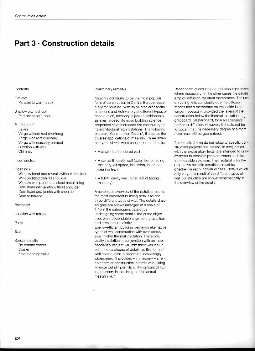
Flat roof Masonry continues to be the most popular employ diffusion-resistant membranes. The useParapet to warm deck form of construction in Central Europe, espe- of roofing felts sufficiently open to diffusion
cially for housing. With its diverse architectur- means that a membrane on the inside is noShallow pitched rodf al options and rich variety of different types of longer necessary, provided the layers of the
Parapet to cold deck construction, masonry is just as fashionable construction below the thermal insulation, e.g.as ever. Indeed, its good building science chipboard, plasterboard, form an adequate
Pitched roof properties have increased the vocabulary of barrier to diffusion. However, it should not beEaves its architectural manifestations. The following forgotten that the necessary degree of airtight-Verge without roof overhang chapter, "Construction Details", illustrates the ness must still be guaranteed.Verge with roof overhang diverse applications of masonry. Three differ-Verge with masonry parapet ent types of wall were chosen for the details: The details shown do not relate to specific con-Junction with wall struction projects but instead, in conjunctionChimney . A single-leaf rendered wall with the explanatory texts, are intended to draw
attention to possible problem zones and il lus-Floor junction . A partial{ill cavity wall (outer leaf of facing trate feasible solutions. Their suitability for the
masonry, air space, insulation, inner load- respective climatic conditions must beOpenings bearing leaf) checked in each individual case. Details which
Window head and reveals without shoulder only vary as a result of the different types ofWindow fitted behind shoulder . A full{ i l l cavity wall (outer leaf of facing wall construction are shown schematically inWindow with peripheral sheet metal l ining masonry) the overview of the details.Door head and jambs without shoulderDoor head and jambs with shoulder A schematic overview of the details presentsDoor to terrace the most important building details for the
three different types of wall. The details shad-Balconies ed grey are shown enlarged at a scale of
1 :10 in the subsequent catalogue.Junction with terrace In designing these details, the prime objec-
tives were dependable engineering qualit iesPlinth and archiiectural claritv.
Energy-eff icient buildin g demands alternativeStairs types of wall construction with ever better,
ever thicker thermal insulation. Therefore,Special details cavity insulation in conjunction with an inde-
Re-entrant corner pendent outer leaf 240 mm thick was includ-Corner ed in the catalogue of details as this form ofFree-standing walls wall construction is becoming increasingly
widespread. lt provides - in masonry - a reli-able form of construction in terms of buildingscience but sti l l permits all the options of fac-ing masonry in the design of the actualmasonrv skin.
204
Overview
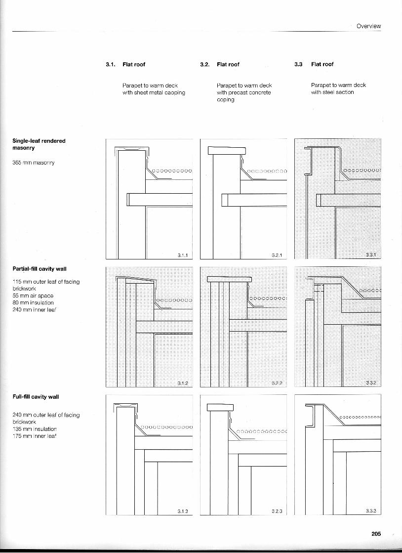
3.1. Flat roof
Parapet to warm deckwith sheet metal capping
3.2. Flat roof
Parapet to warm deckwith precast concretecoping
Flat roof
Parapet to warm deckwith steel section
Single-leaf renderedmasonry
365 mm masonry
Partial-fill cavity wall
1 15 mm outer leaf of facingbrickworkt r t r ' n ' n ^ i - ^ ^ ^ ^ ^uu i l i l i l d i l opqvE
80 mm insulation240 mm inner leaf
Full-fill cavity wall
240 mm outer leaf of facingbrickwork135 mm insulation175 mm inner leaf
m5
o o o o o o o o o o o o o o o o o o o
o o o o o o o oo o o o o o o o
o o o o o o o o o o o
U..ooooo
Construction details
Shallow pitched roof
Parapet to cold deckwith sheet metal capping
Pitched roof
Eaves
Pitched roof
Vergewithout roof overhang
Single-leaf renderedmasonry
365 mm masonry
Partial-fill cavity wall
.1 15 mm outer leaf of facingbrickwork55 mm air space80 mm insulation240 mm inner leaf
Full-fill cavity wall
240 mm outer leaf of facingbrickwork135 mm insulation175 mm inner leaf
206
Overview
3.7 Pitched roof
Vergewith roof overhang
Pitched roof
Vergewith masonry parapet
Pitched roof
Junction with wall
/i\------Z-'.-t . , -
3.9.3
3.10 Pitched roof
Chimney
207
Construction details
Single-leaf renderedmasonry
365 mm masonry
Partial-fill cavity wall
1 15 mm outer leaf of facingbrickwork55 mm air space80 mm insulation240 mm inner leaf
Full-fill cavity wall
240 mm outer leaf of facingbrickwork135 mm insulation175 mm inner leaf
3.1'l Floor junction
3.11 .2
3 . 1 1 , 3
3.12 Openings
Window head and revealswithout shoulder
3.13 Openings
Window head and revealswithout shoulderwith roller blind
IIItl l
l '
I o . | 1 . 2
208
Overview
3.14 Openings
Window fitted behindshoulder
3.15 Openings
Windowwith peripheral sheetmetal l ining
3.16 Openings
Door head and jambswithout shoulder
3.17 Openings
Door head and jambswith shoulder
3.17 .2
209
Construction details
Single-leaf renderedmasonry
365 mm masonry
Partial-fill cavity wall
115 mm outer leaf of facingbrickwork55 mm air space80 mm insulation240 mm inner ieaf
Full-fill cavity wall
240 mm outer leaf of facingbrickwork135 mm insulation175 mm inner leaf
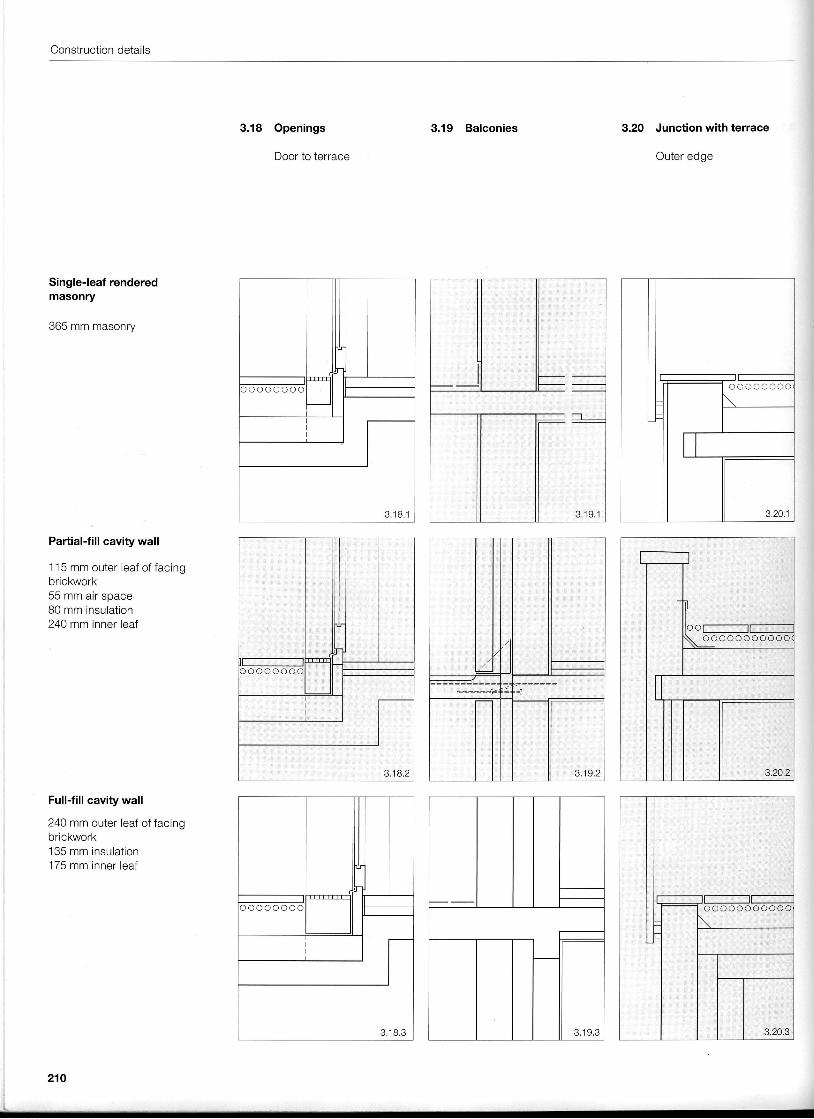
3.18 Openings
Door to terrace
3.19 Balconies
3.19.2
3 .19 ,3
3.2O Junction with terrace
Outer edge
o o o o o o o o o o
210
Overview
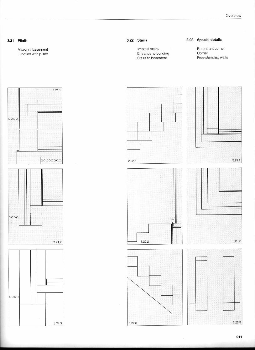
3.2'l Plinth
Masonry basementJunction with plinth
c o o o
3,21 .3
3.22 Stairs
lnternal stairsEntrance to buildingStairs to basement
3.23 Special details
Re-entrant cornerCornerFree-standing walls
,,]i';.;,,1;
*..:.:..::..':..
A: ]
. ...,):':. ,:..1. .:l::.:: a:...':,..::.:.
J , Z | . Z
Construction details
.10
C C O O (
6
C O C O O C O
2
3
4
J . t . z
) C C ' )
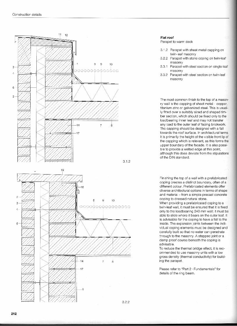
Flat roofParapet to warm deck
3.1 .2 Parapet with sheet metal.capping onfurin-leaf masonry
3.2.2 Parapet with stone coping on twin-leafmasonry
3.3.1 Parapet with steel section on single-leafmasonry
3.3.2 Parapet with steel section on twin-leafmasonry
The most common finish to the top of a mason-ry wall is the capping of sheet metal - copper,titanium-zinc or galvanized steel. This is usual-ly f itted over a suitably sized and shaped tim-ber section, which should be fixed only to theloadbearing inner leaf and may not transferany load to the outer leaf of facing brickwork,The capping should be designed with a falltowards the roof surface. In architectural termsit is primarily the height of the visible front l ip ofthe capping which is relevant, as this forms theupper boundary of the facade. lt is also possi-ble to provide a welted edge at this point,although this does deviate from the stipulationsof the DIN standard.
Finishing the top of a wall with a prefabricatedcoping creates a distinct boundary, often of ad ifferent colour. Prefabricated elements offerdiverse architectural options in terms of shapeand material - from a simple precast concretecoping to dressed natural stone.When providing a prefabricated coping to atwin-leaf wall, it must be ensured that it is fixedonly to the loadbearing 240 mm wall; i t must beable to slide where it bears on the outer leaf. ltis advisable for the coping to have a fall to theinside. The expansion loints between the indi-vidual coping elements must be designed andcarefully built so that no water can penetratethrough to the masonry, A stepped joint or adamp proof course beneath the coping isadvisable.To reduce the thermal bridge effect, it is rec-ommended to use masonry units with a lowgross density (thermal conductivity) for build-i n n i h a n a r a n a t
Please refer to "Part 2 . Fundamentals" fordetails of the ring beam.
ij
l
- l
oc cc co
212
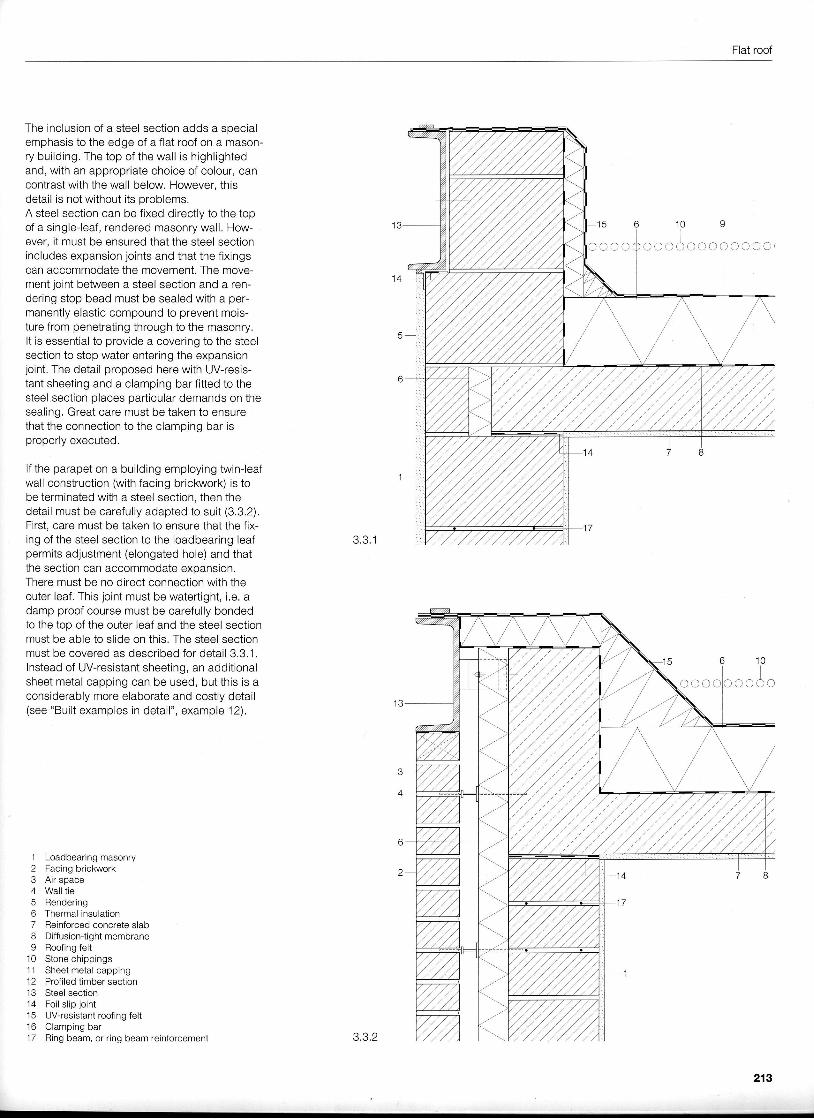
Flat roof
The inclusion of a steel section adds a specialemphasis to the edge of a flat roof on a mason-ry building. The top of the wall is highlightedand, with an appropriate choice of colour, cancontrast with the wall below. However, thisdetail is not without its problems.A steel section can be fixed directly to the topof a single-leaf, rendered masonry wall, How-ever, it must be ensured that the steel sectionincludes expansion joints and that the fixingscan accommodate the movement. The move-ment joint between a steel section and a ren-dering stop bead must be sealed with a per-manently elastic compound to prevent mois-ture from penetrating through to the masonry.It is essential to provide a covering to the steelsection to stop water entering the expansionjolnt, The detail proposed here with UV-resis-tant sheeting and a clamping bar fitted to thesteel section olaces oarticular demands on thesealing. Great care must be taken to ensurethat the connection to the clamping bar isproperly executed.
lf the parapet on a building employing twin-leafwall construction (with facing brickwork) is tobe terminated with a steel section, then thedetail must be carefully adapted to suit (3.3.2).First, care must be taken to ensure that the fix-ing of the steel section to the loadbearing leaf 3.3.1permits adjustment (elongated hole) and thatthe section can accommodate expansion.There must be no direct connection with theouter leaf. This joint must be watertight, i.e. adamp proof course must be carefully bondedto the top of the outer leaf and the steel sectionmust be able to slide on this. The steel sectionmust be covered as described for detail 3.3,1.lnstead of UV-resistant sheeting, an additionalsheet metal capping can be used, but this is aconsiderably more elaborate and costly detail(see "Built examples in detail", example'12).
1 Loadbearing masonry2 Facing brickwork3 Air space4 Wall tie5 Rendering6 Thermal insulation7 Reinforced concrete slab8 DiffusiontightmembraneI Roofing felt
.10 Stone chippings
1 1 Sheet metal capping12 Profiled timber section13 Steel section14 Foi l s l ip jo int15 Uv-resistantroofing felt16 Clamping bar17 Ring beam, or ring beam reinforcement 3.3.2
t c
o O O O (
1 0
oooAcoo
213
Construction details
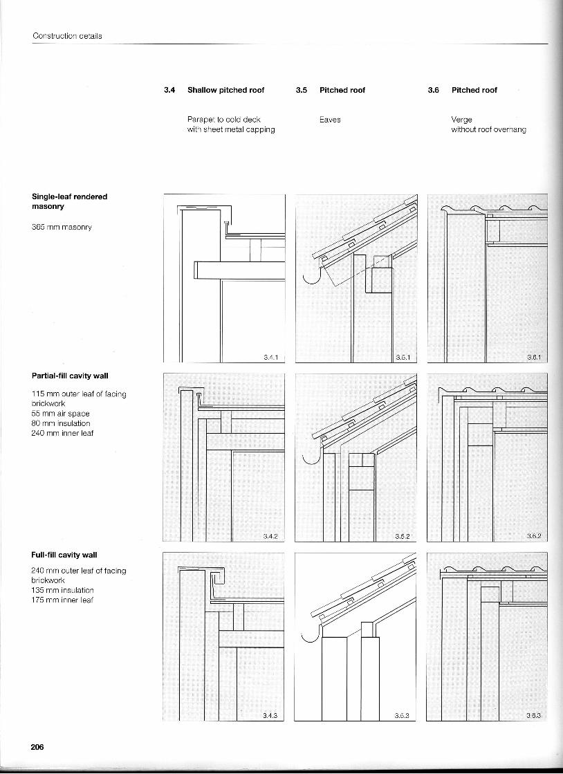
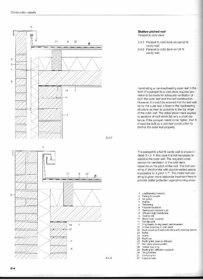
Shallow pitched roofParapet to cold deck
3.4.2 Parapet to cold deck on partial-fillcavity wall
3.4.3 Parapet to cold deck on full-f i l lcavity wall
Terminating a non-loadbearing outer leaf in theform of a parapet to a cold deck requires pro-vision to be made for adequate ventilation ofboth the outer leaf and the roof conStruction.However, it should be ensured that the last walltie for the outer leaf is fixed to the loadbearingstructure as near as possible to the top edgeof the outer leaf. The detail shown here aopliesto sections of roof which fall only a shotl dis-tance. lf the parapet needs to be higher, then itshould be built as a twin-leaf construction toanchor the outer leaf properly,
3.4.2
The parapet to a full-fill cavity wall is shown indetail 3.4.2. In this case it is not necessary iostabilize the outer leaf. The required cross-section for ventilation of the cold deckdepends on the pitch of the roof. The roof cov-ering of sheet metal with double-welted seamsis possible for a pitch > 7'. The metal roof cov-ering is given more elaborate treatment here toprovide better protection against driving snow.
1 Loadbearing masonryC t r^^ i^^ h r inku in rk
e A i r c n a ^ a
4 Wa l l t i eq Ran. l6 r in^
6 Thermal insulation7 Reinforced concrete slab8 Diffusion-tight membrane9 Roofing felt
1 1 Sheet metal capping1 1 F n i l s l i n i n i n i
17 Ring beam, or ring beam reinforcement21 Timber boarding of cold deck22 Roof covering of metal sheeting with standing seams23 Rafter24 Gutter25 Roof tileslb Hooflng Tert, open to ornusron27 Wall plate (eaves purlin)26 rmoer ooarorng29 Roofing felt, diffusion-resistant30 Tiling battense 1 C l a m n i n n h a r
3.4.3 37 Insect screen
214
Pitched roof
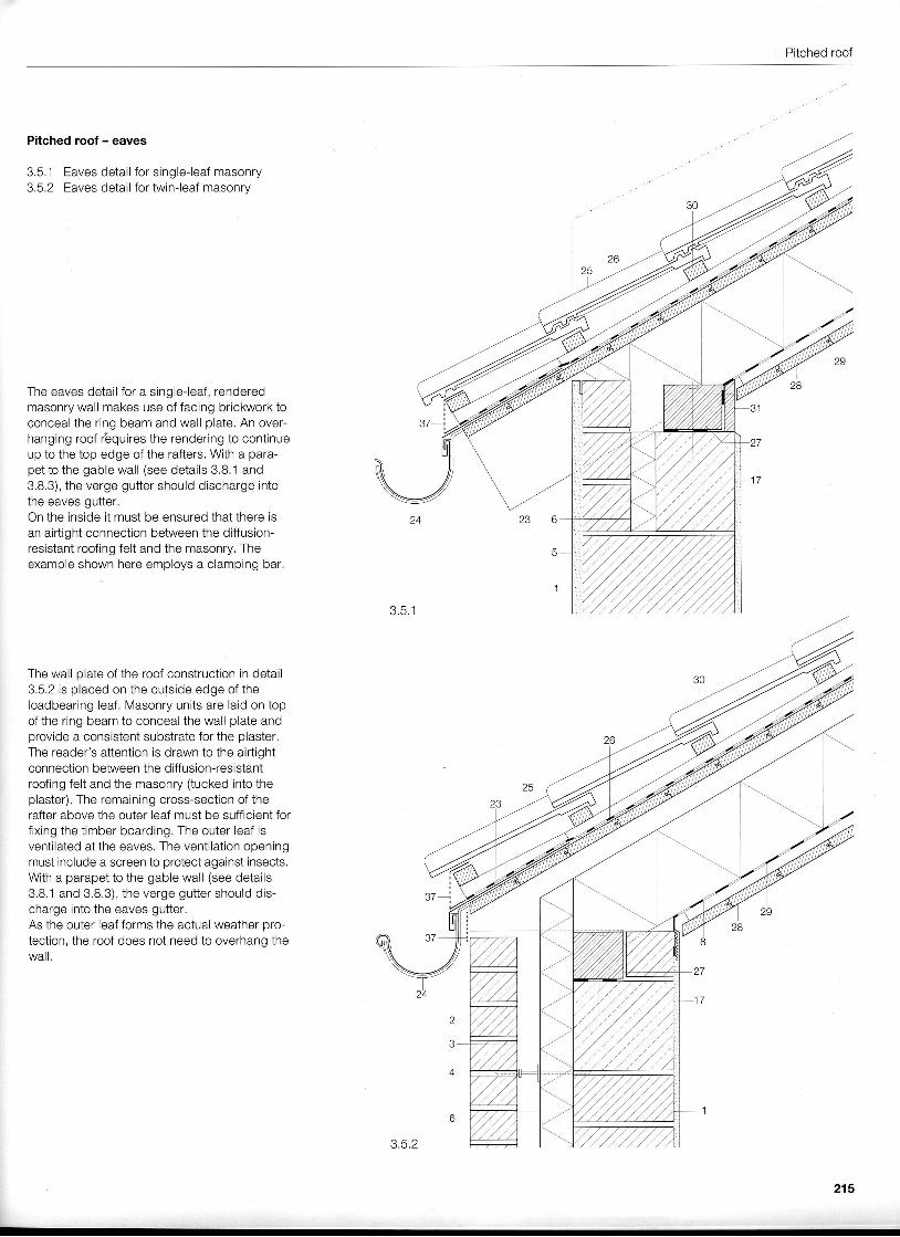
Pitched roof - eaves
3.5.1 Eaves detail for single-leaf masonry3.5.2 Eaves detail for twin-leaf masonrv
The eaves detail for a single-leaf, renderedmasonry wall makes use of facing brickwork toconceal the ring beam and wall plate. An over-hanging roof r 'equires the rendering to continueup to the top edge of the rafters. With a para-pet to the gable wall (see details 3,8.1 and3.8.3), the verge gutter should discharge intothe eaves gutter.On the inside it must be ensured that there isan airtight connection between the diffusion-resistant roofing felt and the masonry. Theexample shown here employs a clamping bar.
The wall plate of the roof construction in detail3.5.2 is placed on the outside edge of theloadbearing leaf. Masonry units are laid on topof the ring beam to conceal the wall plate andprovide a consistent substrate for the plaster,The reader's attention is drawn to the airtightconnection between the diffusion-resistantroofing felt and the masonry (tucked into theplaster). The remaining cross-section of therafter above the outer leaf must be sufficient forfixing the timber boarding. The outer leaf isventilated at the eaves. The ventilation openingmust include a screen to protect against insects.With a parapet to the gable wall (see details3.8.1 and 3.8.3), the verge gutter should dis-charge into the eaves gutter.As the outer leaf forms the actual weather oro-tection, the roof does not need to overhang thewail,
215
Construction details
3 .6 .1
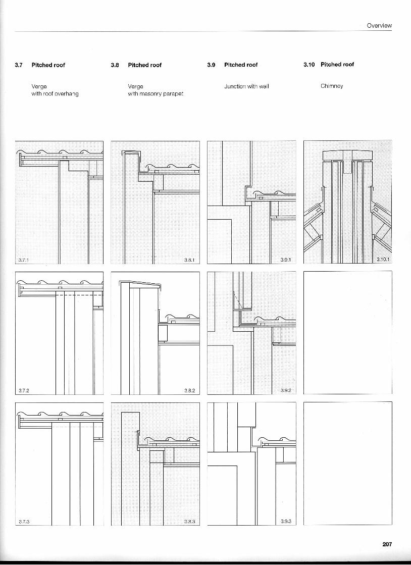
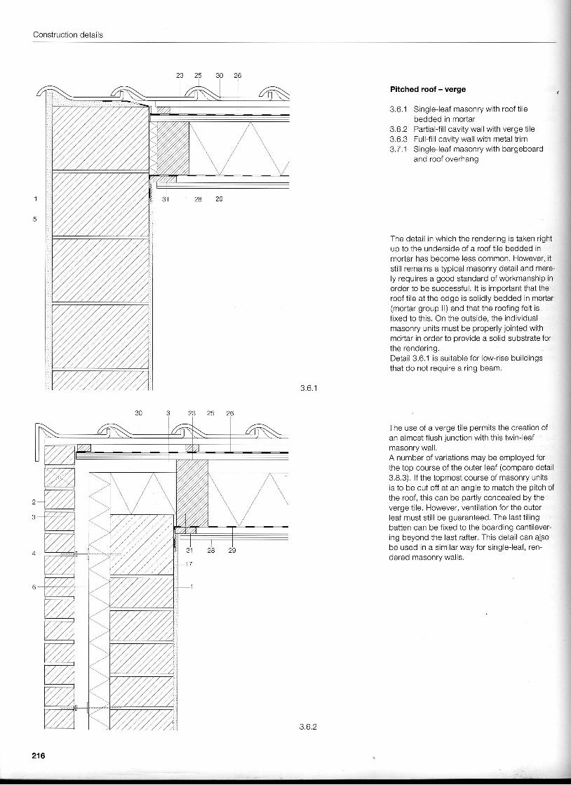
Pitched roof - verge
3.6.1 Single-leaf masonry with roof t i lebedded in mortar
3.6.2 Partial-f i l l cavity wall with verge ti le3.6.3 FullJi l l cavity wall with metal trim3.7.1 Single-leaf masonry with bargeboard
and roof overhang
The detail in which the rendering is taken rightup to the underside of a roof t i le bedded inmortar has become less common. However, itstill remains a typical masonry detail and mere-ly requires a good standard of workmanship inorder to be successful. lt is important that theroof t i le at the edge is solidly bedded in mortar(mortar group ll) and that the roofing felt isfixed to this. On the outside, the individualmasonry units must be properly jointed withmohar in order to provide a solid substrate forthe rendering.Detail 3.6.1 is suitable for low-rise buildingsthat do not require a ring beam.
The use of a verge tile permits the creation ofan almost flush junction with this twin-leafmasonry wail.A number of variations may be employed forthe top course of the outer leaf (compare detail3.8.3). lf the topmost course of masonry unitsis to be cut off at an angle to match the pitch ofthe roof, this can be partly concealed by theverge tile. However, ventilation for the outerleaf must sti l l be guaranteed. The last t i l ingbatten can be fixed to the boarding cantilever-ing beyond the last rafter. This detail can alsobe used in a similar way for single-leaf, ren-dered masonry walls.
216
3.6.2
-;
Pitched roof
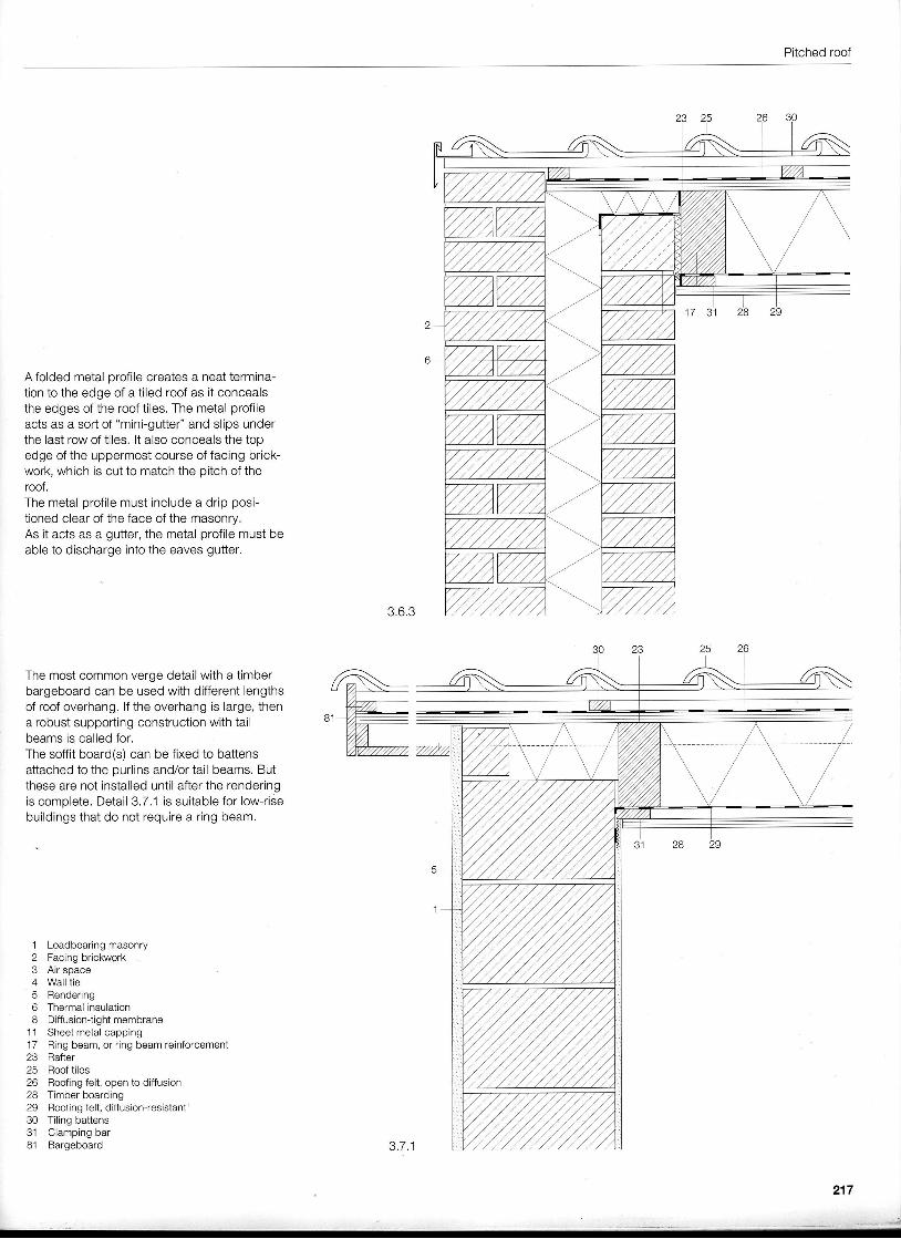
A folded metal orofile creates a neat termina-tion to the edge of a tiled roof as it concealsthe edges of the roof tiles. The metal profileacts as a sort of "mini-gutter" and slips underthe last row of tiles. lt also conceals the topedge of the uppermost course of facing brick-work, which is cut to match the pitch of theroof.The metal profi le must include a drip posi-tioned clear of the face of the masonry.As it acts as a gutter, the metal profile must beable to discharge into the eaves gutter.
3.6.3
The most common verge detail with a timberbargeboard can be used with different lengthsof roof overhang. lf the overhang is large, thena robust supporting construction with tailbeams is called for.The soffit board(s) can be fixed to battensattached to the purlins and/or tail beams. Butthese are not installed until after the renderingis complete. Detail 3.7,1 is suitable for low-risebuildings that do not require a ring beam.
1 Loadbearing masonry2 Facing brickwerk3 Air space4 Wall tie5 Rendering6 Thermal insulation8 Diffusion{ightmembrane
11 Sheet metal capping17 Ring beam, or ring beam reinforcement23 Rafter25 Roof tiles26 Roofing felt, open to diffusion28 Timber boarding29 Roofingfelt, diffusion-resistant30 Tiling battens31 Clamping bar81 Bargeboard 3.7.1
217
,_.__- . _=....., ,.*"il
Construction details
Pitched roof - verge
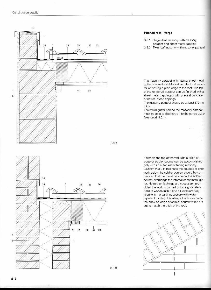
3.8.1 Single-leaf masonry with masonryparapet and sheet metal capplng
3.8,3 Twin-leaf masonry with masonry parapet
The masonry parapet with internal sheet metalgutter is a well-established architectural meansfor achieving a plain edge to the roof. The topof the rendered oaraoet can be finished with asheet metal capping or with precast concreteor natural stone copings.The masonry parapet should be at least 175 mmthick.The metal gutter behind the masonry parapetmust be able to discharge into the eaves gutter(see deta i l 3 .5.1) .
Finishing the top of the wall with a brick-on-edge or soldier course can be accomplishedonly with an outer leaf of facing masonry24O mm thick. ln this case the courses of brick-work below the soldier course should be cutback so that the metal drip below the soldiercourse overhangs the internal sheet metal gut-ter. No further flashings are necessary, pro-vided the work is carried out to a good stan-dard of workmanship and all joints are fullyfilled with mortar (if necessary with water-repellent mortar). lt is always the bricks belowthe brick-on-edge or soldier course which arecut to match the pitch of the roof.
III
{j
i
,lj:|iI
lI
j
::
3 .8 .1
218
3.8.3
Pitched roof
Pitched roof - junction with wall
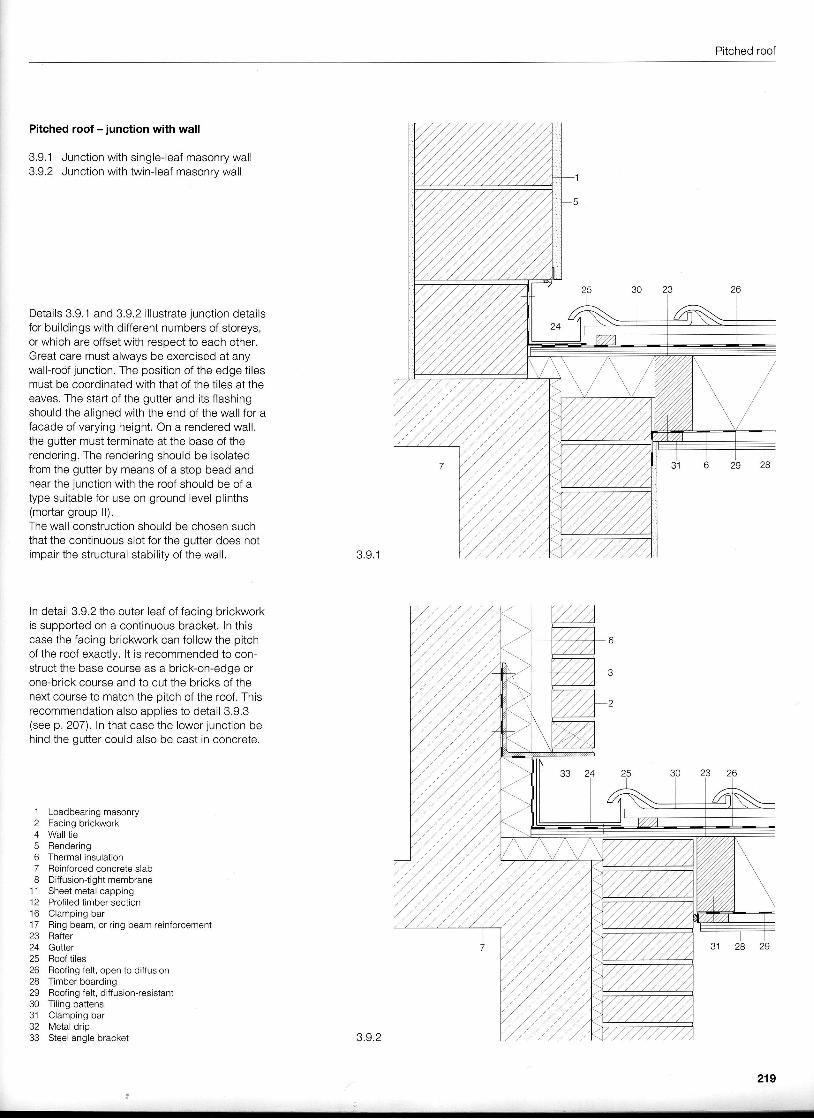
3.9,1 Junction with single-leaf masonry wall3.9.2 Junction with twin-leaf masonrv wall
Details 3.9,1 and 3.9.2 i l lustrate junction detailsfor buildings with different numbers of storeys,or which are offset with respect to each other.Great care must always be exercised at anywall-roof junction. The position of the edge ti lesmust be coordinated with that of the tiles at theeaves. The start of the gutter and its flashingshould the aligned with the end of the wall for afacade of varying height. On a rendered wall,the gutter must terminate at the base of therendering, The rendering should be isolatedfrom the gutter by means of a stop bead andnear the junction with the roof should be of atype suitable for use on ground level plinths(mortar group ll).The wall construction should be chosen suchthat the continuous slot for the gutter does notimpair the structural stabil ity of the wall. 3.9.1
In detail 3.9,2 the outer leaf of facing brickworkis supported on a continuous bracket. ln thiscase the facing brickwork can follow the pitchof the roof exactly. lt is recommended to con-struct the base course as a brick-on-edge orone-brick course and to cut the bricks of thenext course to match the pitch of the roof. Thisrecommendation also apolies to detail 3.9.3(see p. 207). In that case the lower junction be-hind the qutter could also be cast in concrete.
1 Loadbearing masonry2 Facing brickwork4 Wall tie5 Rendering6 Thermal insulation7 Reinforced concrete slab8 Diffusion-tight membrane
11 Sheet metal capping12 Profiled timber section16 Clamping bar17 Ring beam, or ring beam reinforcement23 Rafter24 Gutter25 Roof tiles26 Roofing felt, open to diffusion28 Timber boarding29 Roofing felt, diffusion-resistant30 Tiling battens31 Clamping bar32 Metal drip33 Steel angle bracket 3.9.2
219
Construction details
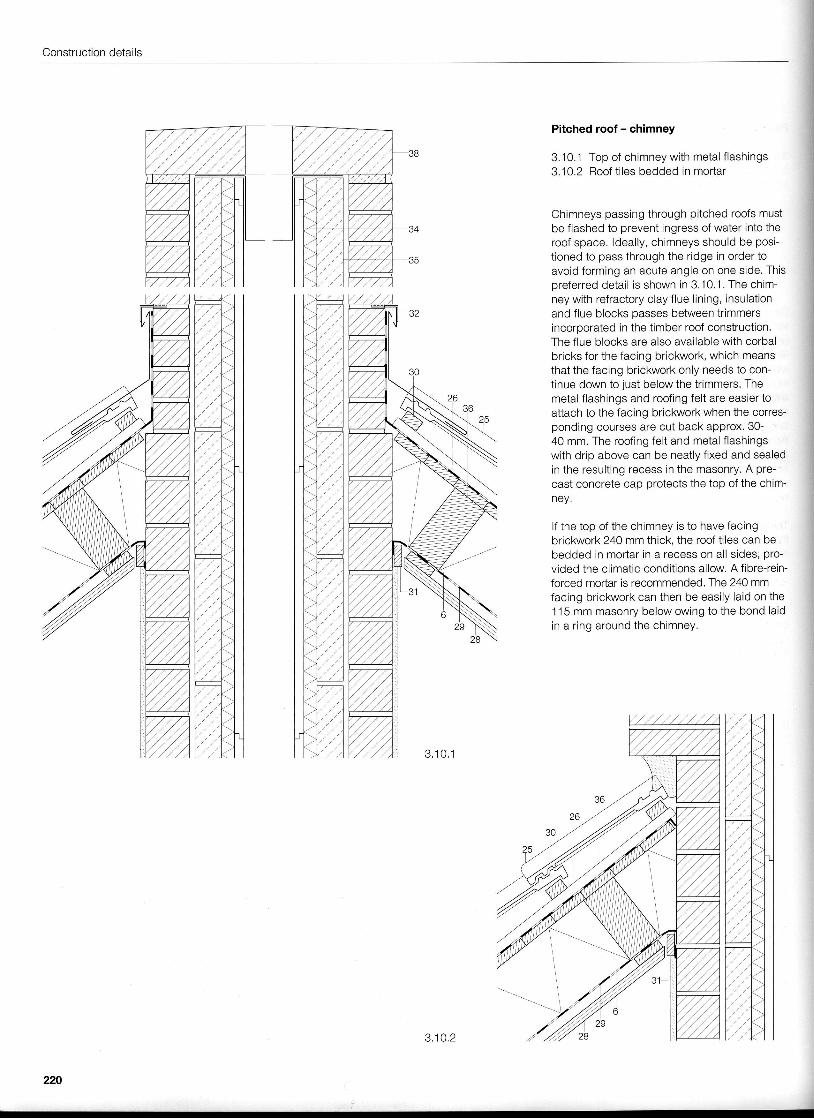
Pitched roof - chimney
3.10.1 Top of chimney with metal f lashings3.1 0.2 Roof ti les bedded in mortar
Chimneys passing through pitched roofs mustbe flashed to prevent ingress of water into theroof space. ldeally, chimneys should be posi-tioned to pass through the ridge in order toavoid forming an acute angle on one side. Thispreferred detail is shown in 3. 1 0.1 . The chim-ney with refractory clay flue l ining, insulationand flue blocks passes between trimmersincoroorated in the timber roof construction.The flue blocks are also available with corbalbricks for the facing brickwork, which meansthat the facing brickwork only needs to con-tinue down to just below the trimmers. Themetal flashings and roofing felt are easier toattach to the facing brickwork when the corres-ponding courses are cut back approx. 30-40 mm. The roofing felt and metal f lashingswith drip above can be neatly f ixed and sealedin the resulting recess in the masonry. A pre-cast concrete cap protects the top of the chim-ney.
lf the top of the chimney is to have facingbrickwork 240 mm thick, the roof tiles can bebedded in mortar in a recess on all sides, pro-vided the climatic conditions allow. A fibre-rein-forced mortar is recommended. The 240 mmfacing brickwork can then be easily laid on the115 mm masonry below owing to the bond laidin a ring around the chimney.
220
3,10.2
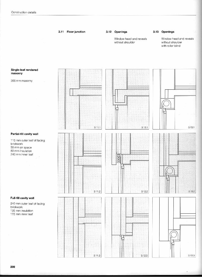
Floor junction
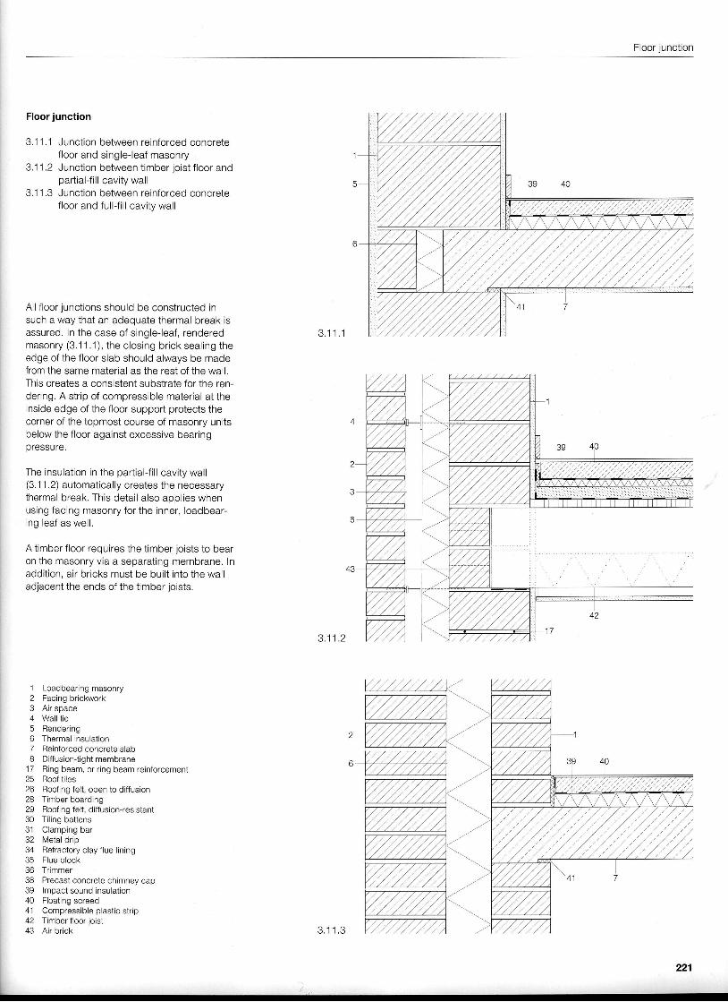
Floor junction
3.11.1 Junction between reinforced concretefloor and single-leaf masonry
3.11.2 Junction between timber joist f loor andpartial-fill cavity wall
3.11.3 Junction between reinforced concretefloor and full-f i l l cavity wall
All floor junctions should be constructed insuch a way that an adequate thermal break isassured. ln the case of single-leaf, rendered 3.11.1masonry (3.1 1 .1 ), the closing brick sealing theedge of the floor slab should always be madefrom the same material as the rest of the wall.This creates a consistent substrate for the ren-dering. A strip of compressible material at theinside edge of the floor support protects thecorner of the topmost course of masonry unitsbelow the floor against excessive bearingpressure.
The insulation in the partial-f i l l cavity wall(3.11.2) automatically creates the necessarythermal break. This detail also apolies whenusing facing masonry for the inner, loadbear-ing leaf as well.
A timber floor requires the timber joists to bearon the masonry via a separating membrane. lnaddition, air bricks must be built into the walladjacent the ends of the timber joists.
3 .11 .2
.l Loadbearing masonry2 Facing brickwork3 Air space4 Wall tie5 Rendering6 Thermal insulation7 Reinforced concrete siabI Diffusion{ightmembrane
17 Ring beam, or ring beam reinforcement25 Roof tiles26 Roofing felt, open to diffusion28 Timber boarding29 Roofing felt, diffusion-resistant30 Tiling battens31 Clamping bar32 Metal drip34 Refraclory clay flue lining35 Flue block36 Trimmer38 Precast concrete chimney cap39 lmpact sound insulation40 Floating screed41 Compressible plastic strip42 Timber floor joist43 A i r b r i c k 3 .11 .3
Construction details
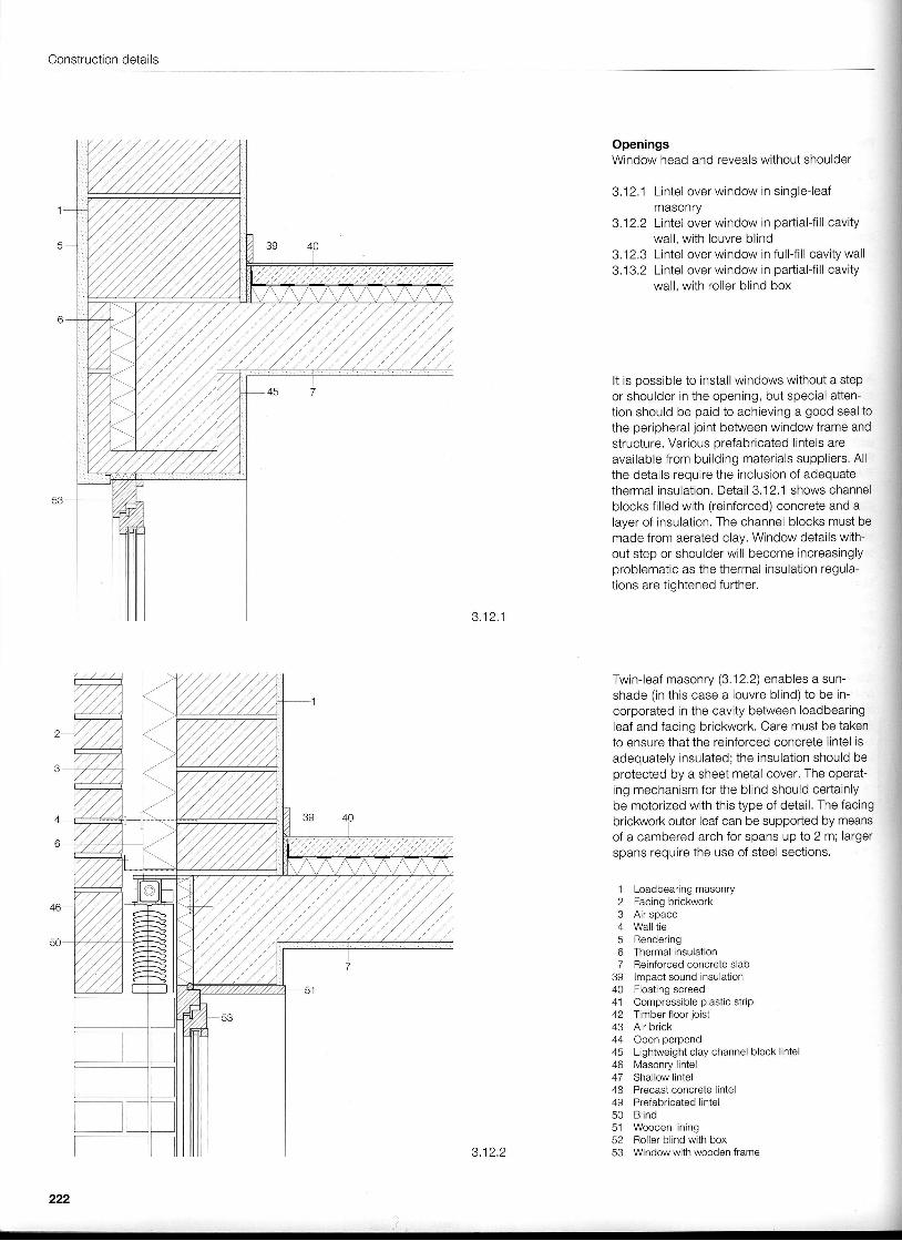
OpeningsWindow head and reveals without shoulder
3.12,1 Lintel over window in single-leafmasonry
3.12,2 Lintel over window in partial{i l l cavitywall, with louvre blind
3,12,3 Lintel over window in fullJi l l cavity wall3.13.2 Lintel over window in partial-f i l l cavity
wall, with roller blind box
It is possible to install windows without a stepor shoulder in the opening, but special atten-tion should be paid to achieving a good seal tothe peripheral joint between window frame andstructure. Various prefabricated lintels areavailable from building materials suppliers. Allthe details require the inclusion of adequatethermal insulation. Detail 3.12.1 shows channelblocks fi l led with (reinforced) concrete and alayer of insulation, The channel blocks must bemade from aerated clay. Window details with-out step or shoulder wil l become increastnglyproblematic as the thermal insulation regula-tions are tightened further.
3 . 1 2 . 1
Twin-leaf masonry (3.12,2) enables a sun-shade (in this case a louvre blind) to be in-corporated in the cavity between loadbearingeaf and facing brickwork. Care must be takento ensure that the reinforced concrete lintel isadequately insulated; the insulation should beprotected by a sheet metal cover, The operat-ng mechanism for the blind should certainlybe motorized with this type of detail. The facingbrickwork outer leaf can be supported by meansof a cambered arch for spans up to 2 m; largerspans require the use of steel sections.
1 Loadbearing masonry2 Facing brickwork3 Air space4 Wall tie5 Render ing6 Thermal insulation7 Reinforced concrete slab
]l ffil'."*.,"47 Shallow lintel48 Precast concrete lintel49 Prefabricated lintel
51 Wooden lining52 Roller blind with box
3.12.2 53 Window with wooden frame
222
Openings
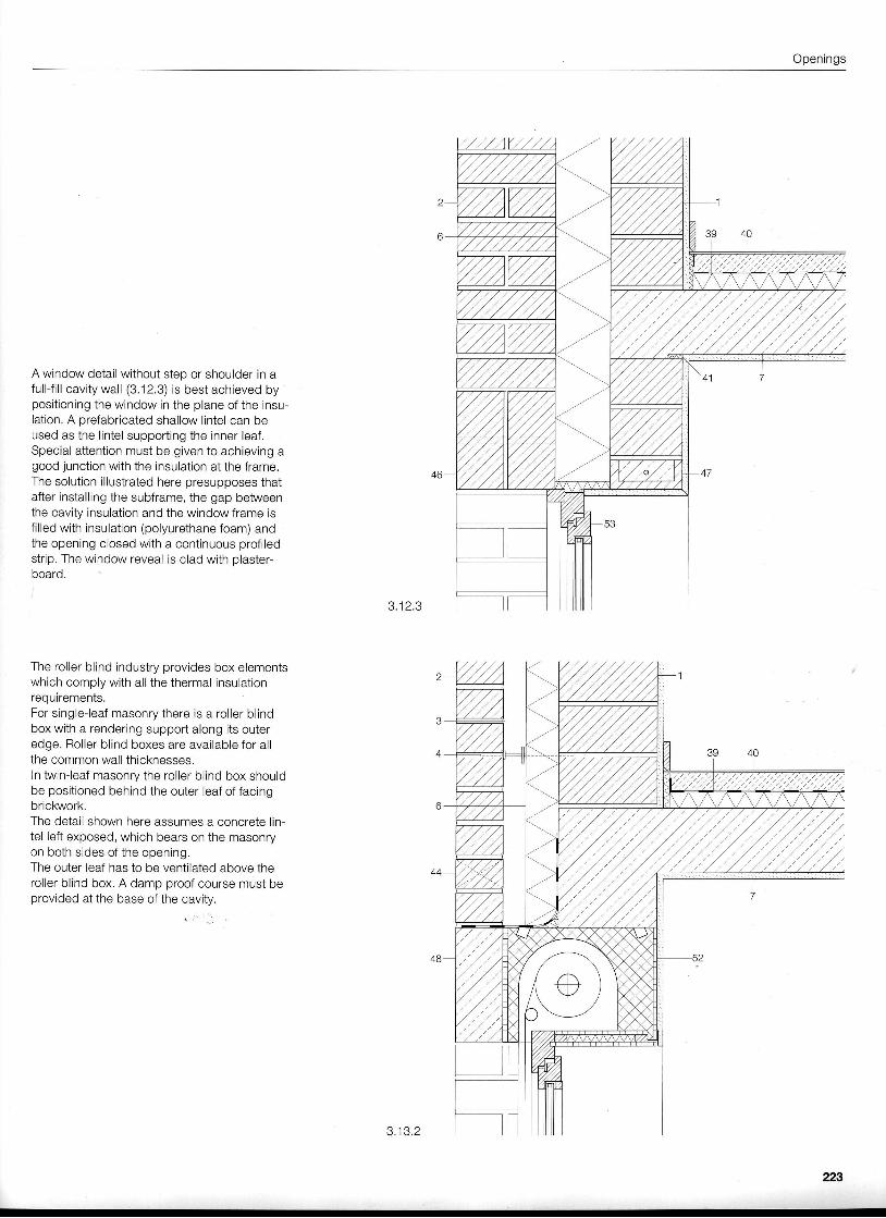
A window detail without step or shoulder in afull-f i l l cavity wall (3.12.3) is best achieved bypositioning the window in the plane of the insu-lation. A prefabricated shallow lintel can beused as the l intel suppofting the inner leaf.Special attention must be given to achieving agood junction with the insulation at the frame.The solution illustrated here presupposes thatafter installing the subframe, the gap betweenthe cavity insulation and the window frame isfi l led with insulation (polyurethane foam) andthe opening closed with a continuous profi ledstrip. The window reveal is clad with plaster-board.
The roller blind industry provides box elementswhich comply with all the thermal insulationrequirements.For single-leaf masonry there is a roller blindbox with a rendering support along its outeredge. Roller blind boxes are available for allthe common wall thicknesses.In twin-leaf masonry the roller blind box shouldbe positioned behind the outer leaf of facingbrickwork.The detail shown here assumes a concrete lin-tel left exposed, which bears on the masonryon both sides of the opening.The outer leaf has to be ventilated above theroller blind box. A damp proof course must beprovided at the base of the cavity.
J . I Z . J
o . I J . Z
223
Construction details
3 ,14 .1
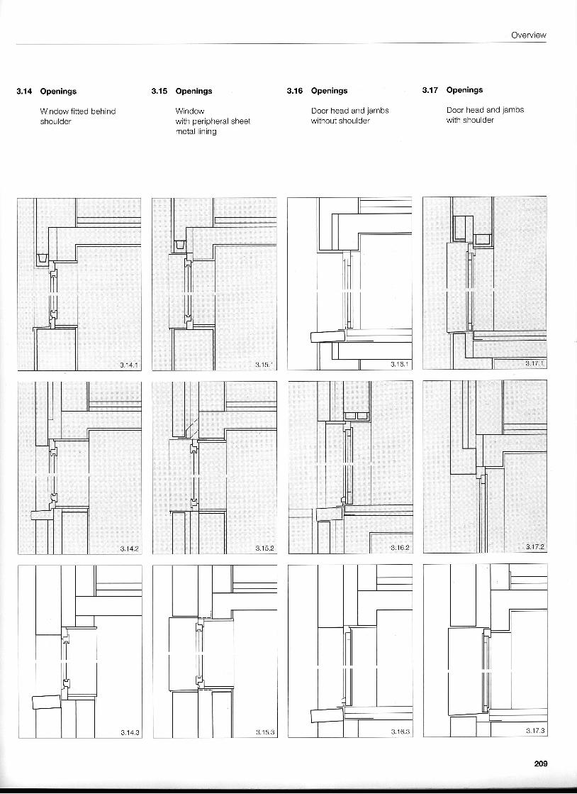
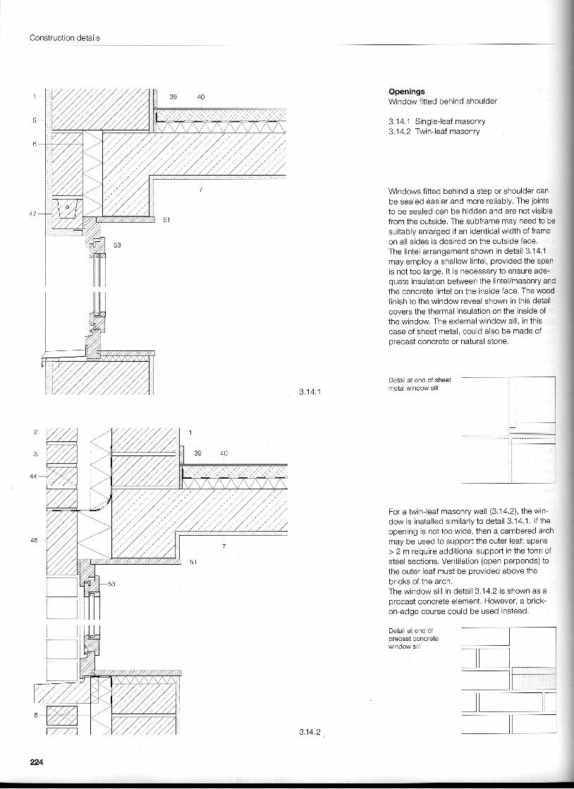
OpeningsWindow fitted behind shoulder
3.14.1 Single- leaf masonry3.1 4.2 Twin-leaf masonry
Windows fitted behind a step or shoulder canbe sealed easier and more reliably. The jointsto be sealed can be hidden and are not visiblefrom the outside. The subframe may need to besuitably enlarged if an identical width of frameon all sides is desired on the outside face,The lintel arrangement shown in detail 3.14.1may employ a shallow lintel, provided the spanis not too large. lt is necessary to ensure ade-quate insulation between the lintel/masonry andthe concrete l intel on the inside face. The woodfinish to the window reveal shown in this detailcovers the thermal insulation on the inside ofthe window. The external window sil l , in thiscase of sheet metal, could also be made ofprecast concrete or natural stone.
Detail at end of sheetmetai window sill
For a twin-leaf masonry wall (3.14.2), the win-dow is installed similarly to detail 3.14.1. lf theopening is not too wide, then a cambered archmay be used to support the outer leaf; spans> 2 m require additional support in the form ofsteel sections. Ventilation (open perpends) tothe outer leaf must be provided above thebricks of the arch.The window sil l in detail 3.14.2 is shown as aprecast concrete element. However, a brick-on-edge course could be used instead.
Detail at end ofprecast concretewindow sill
I
224
3.14.2
Openings
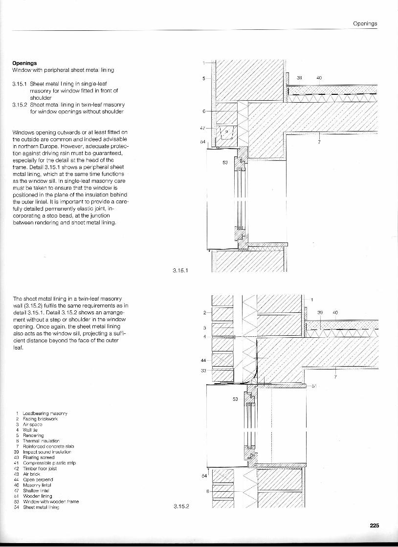
OpeningsWindow with peripheral sheet metal l ining
3.15.1 Sheet metal l in ing in s ingle- leafmasonry for window fitted in front ofshoulder
3.15.2 Sheet metal l ining in twin-leaf masonryfor window openings without shoulder
Windows opening outwards or at least fitted onthe outside are common and indeed advisablein northern Europe. However, adequate protec-tion against driving rain must be guaranteed,especially for the detail at the head of theframe. Detail 3.15.1 shows a peripheral sheetmetal l ining, which at the same time functionsas the window sil l . In single-leaf masonry caremust be taken to ensure that the window ispositioned in the plane of the insulation behindthe outer lintel. lt is important to provide a care-fully detailed permanently elastic joint, in-corporating a stop bead, at the junctionbetween rendering and sheet metal l ining,
The sheet metal l ining in a twin-leaf masonrywall (3.15.2) fulf i ls the same requirements as indetail 3.15.1. Detail 3.15.2 shows an arrange-ment without a steo or shoulder in the windowopening. Once again, the sheet metal l iningalso acts as the window sill, projecting a suffi-cient distance beyond the face ofthe outerleaf.
3 . 1 5 . 1
1 Loadbearing masonry2 Facingbrickwork3 Air space4 Wall tie5 Render ing6 Thermal insulation7 Reinforced concrete slab
39 lmpact sound insulation40 Floating screed41 Compressible plastic strip42 Timber floor joist43 Air brick44 Open perpend46 Masonry lintel47 Shallow lintel51 Wooden lining53 Window with wooden frame54 Sheet metal l in ing 3.15.2
225
Construction details
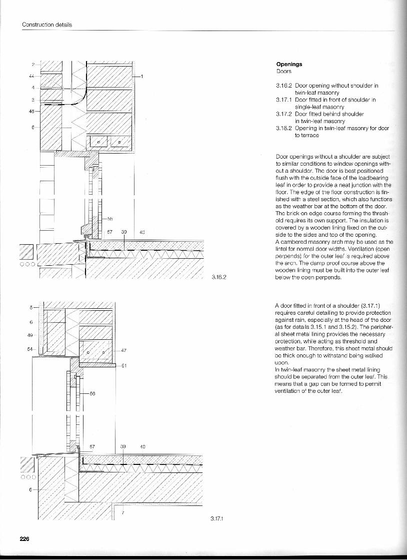
OpeningsDoors
3. 16.2 Door opening without shoulder intwin-leaf masonry
3.1 7.1 Door fitted in front of shoulder inc i n n l a - l a a f m a c n n, , , - , - , , ry
3.17 ,2 Door fitted behind shoulderin twin-leaf masonry
3.1 8.2 Opening in twin-leaf masonry for doorto terrace
Door openings without a shoulder are subjectto similar conditions to window openings with-out a shoulder. The door is best positionedflush with the outside face of the loadbearingleaf in order to provide a neat junction with thefloor. The edge of the floor construction is fin-ished with a steel section, which also functionsas the weather bar at the bottom of the door.The brick-on-edge course forming the thresh-old requires its own support. The insulation iscovered by a wooden lining fixed on the out-side to the sides and top of the opening.A cambered masonry arch may be used as thelintel for normal door widths. Ventilation (openperpends) for the outer leaf is required abovethe arch. The damo oroof course above the
3162 ;ffi*?$:I;;1ffi:::- into the outer ,eaf
A door fitted in front of a shoulder (3.17.1)requires careful detailing to provide protectionagainst rain, especially at the head of the door(as for details 3.15.1 and 3,15,2), The peripher-al sheet metal l ining provides the necessaryprotection, while acting as threshold andweather bar. Therefore, this sheet metal shouldbe thick enough to withstand being walkedupon.In twin-leaf masonry the sheet metal l iningshould be seoarated from the outer leaf. Thismeans that a gap can be formed to permitventilation of the outer leaf.
zooo
226
3.17.1
Openings
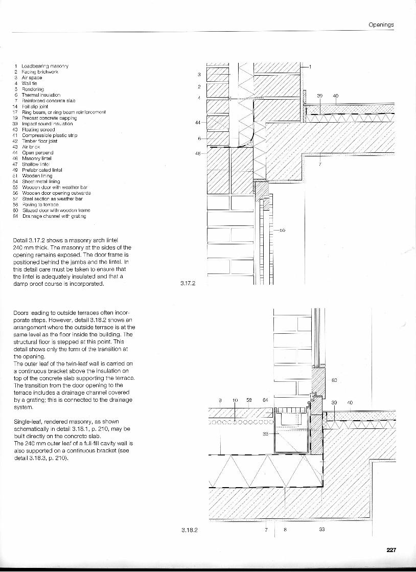
1 Loadbearing masonry2 Facing brickwork3 Air space4 Wall tie5 Rendering6 Thermal insulation7 Reinforced concrete slab
14 Foil slip joint17 Ring beam, or ring beam reinforcement19 Precast concrete capping39 lmpact sound insulation40 Floating screed41 Compressible plastic strip42 Timber floor joist43 Air brick44 Open perpend46 Masonry lintel47 Shallow lintel49 Prefabricated lintel51 Wooden lining54 Sheet metal lining55 Wooden door with weather bar56 Wooden door opening outwards57 Steel section as weather bar6a Dcr r ina t^ +6r re^a
60 Glazed door with wooden frame64 Drainage channel with grating
Detail 3.17.2 shows a masonry arch l intel240 mm thick. The masonry at the sides of theopening remains exposed. The door frame ispositioned behind the jambs and the l intel. Inthis detail care must be taken to ensure thatthe lintel is adequately insulated and that adamp proof course is incorporated. 3.17.2
Doors leading to outside terraces often incor-porate steps. However, detail 3.'18.2 shows anarrangement where the outside terrace is at thesame level as the floor inside the building. Thestructural floor is stepped at this point. Thisdetail shows only the form of the transition atthe opening,The outer leaf of the twin-leaf wall is carried ona continuous bracket above the insulation ontop of the concrete slab supporting the terrace.The transition from the door opening to theterrace includes a drainage channel coveredby a grating; this is connected to the drainagesysrem.
Slngle-leaf, rendered masonry, as shownschematically in detail 3.18.1 , p. 210, may bebuilt directly on the concrete slab.fhe 24O mm outer leaf of a full-fill cavity wall isalso supported on a continuous bracket (seede ta i l 3 .18 .3 , p .210 ) .
3.18.2
227
Construction details
7./a77aa
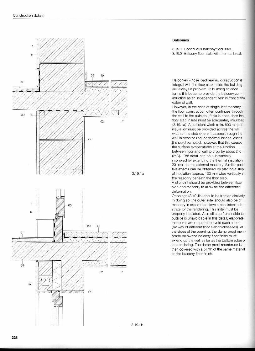
Balconies
3.1 9. 1 Continuous balcony f loor slab3.19.2 Balcony floor slab with thermal break
Balconies whose loadbearing construction isintegral with the floor slab inside the buildingare always a problem. In building scienceterms it is better to provide the balcony con-struction as an independent item ln front of theexternal wall.However, in the case of single-leaf masonry,the floor construction often continues throughthe wall to the outside. lf this is done, then thefloor slab inside must be adequately insulated(3.19.1a) . A suf f ic ientwidth (min.5O0 mm) ofinsulation must be provided across the fullwidth of the slab where it passes through thewall in order to reduce thermal bridge losses.It should be noted, however, that this causesthe surface temperatures at the junctionbetween floor and wall to drop by about 2 K(2'C). The detail can be substantiallyimproved by extending the thermal insulation20 mm into the external masonry. Similar posi-tive effects can be obtained by placing a stripof insulation approx. 100 mm wide vertically inthe masonry beneath the floor slab.A slip joint should be provided between floorslab and masonry to allow for the differentialdeformation.Openings (3.19.1b) should be treated similarly.ln doing so, the outer l intel should also be ofmasonry in order to achieve a consistent sub-strate for the rendering, This l intel must beproperly insulated. A small step from inside tooutside is unavoidable in this detail; elaboratemeasures are required to avoid such a step(by way of different floor slab thicknesses). Atthe sides of the opening, the damp proof mem-brane below the balcony floor f inish mustextend up the wall as far as the bottom edge ofthe rendering. The damp proof membrane isthen covered with a plinth of the same materialas the balcony floor f inish
1
'
3 .1 9 .1 a
228
3 . 1 9 . 1 b
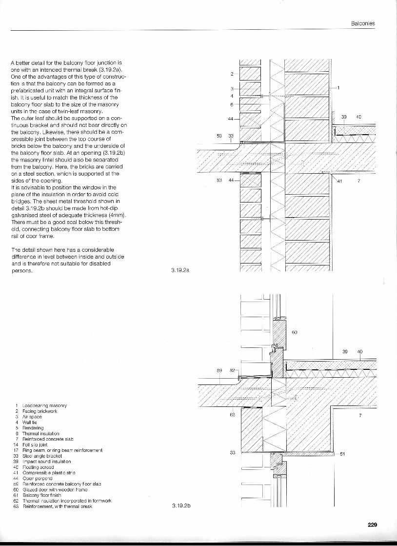
Balconies
A better detail for the balcony floor junction isone with an intended thermal break (3.'19.2a).One of the advantages of this type of construc-tion is that the balcony can be formed as aprefabricated unit with an integral surface fin-ish. lt is useful to match the thickness of thebalcony floor slab to the slze of the masonryunits in the case of twin-leaf masonry.The outer leaf should be supported on a con-tinuous bracket and should not bear directly onthe balcony. Likewise, there should be a com-pressible joint between the top course ofbricks below the balcony and the underside ofthe balcony floor slab, At an opening (3.19.2b)the masonry lintel should also be separatedfrom the balcony. Here, the bricks are carriedon a steel section, which is supported at thesides of the opening.It is advisable to position the window in theplane of the insulation in order to avoid coldbridges. The sheet metal threshold shown indetail 3.19.2b should be made from hofdipgalvanised steel of adequate thickness (4mm).There must be a good seal below this thresh-old, connecting balcony floor slab to bottomrail of door frame.
The detail shown here has a considerabledifference in level between inside and outsideand is therefore not suitable for disabledpersons.
Loadbearing masonryFacing brickworkAir spaceWall tieRenderingThermal insulationReinforced concrete slabFoil slip jointRing beam, or ring beam reinforcementq t a a l . n ^ l a h r . . L 6 t
lmpact sound insulationFloating screedCompressible plastic stripOpen perpendReinforced concrete balcony floor slabGlazed door with wooden frameBalcony floor finishThermal insulation incorporated in formworkReinforcement, with thermal break
'l
234567
-t4
1 733394041445960o l
6263
3.19.2a
3 .19 .2b
229
Construction details
a - -777
1el-tr,---Z--Z--Z--777777777)
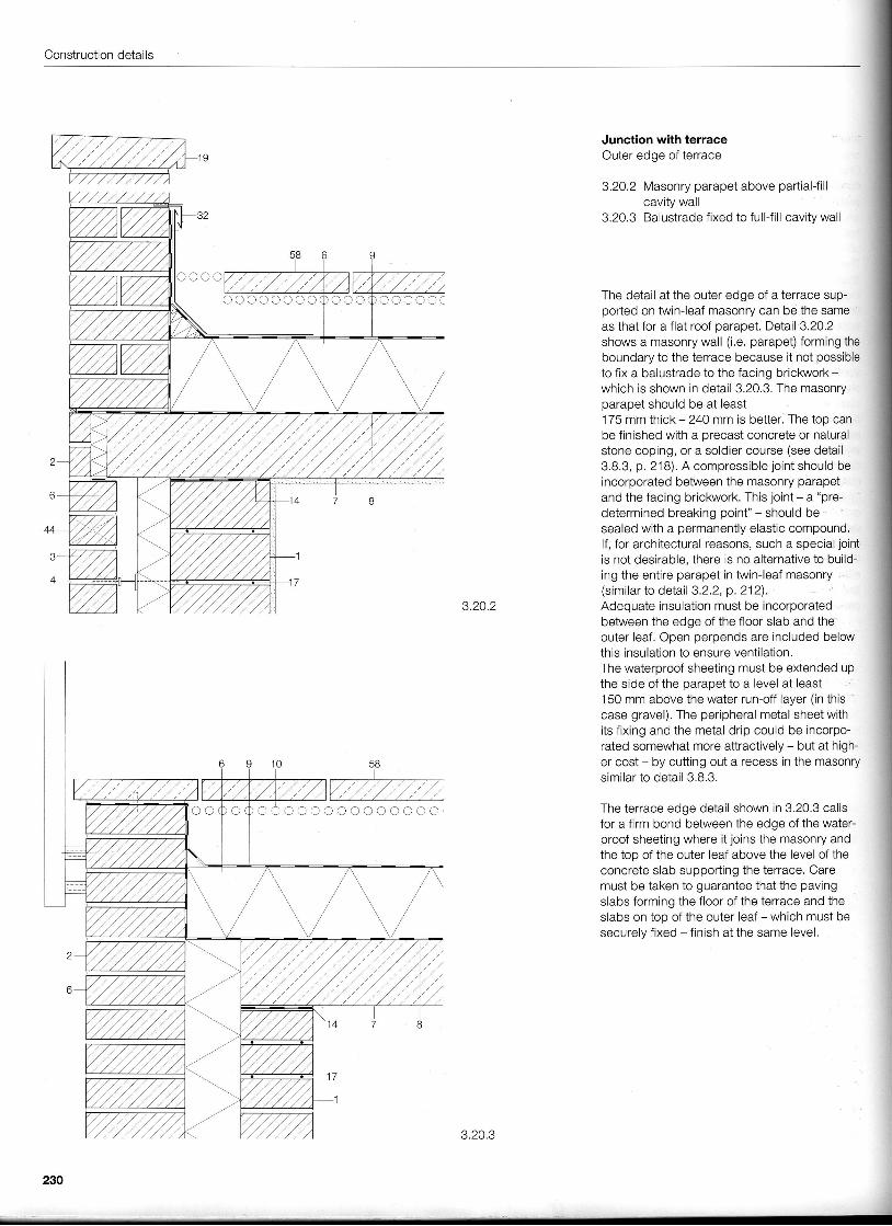
Junction with terraceOuter edge of terrace
3.20.2 Masonry parapet above partial-fillcavity wall
3,20,3 Balustrade fixed to full-f i l l cavity wall
The detail at the outer edge of a terrace sup-ported on twin-leaf masonry can be the sameas that for a flat roof parapet. DeIail 3,20.2shows a masonry wall (i.e, parapet) forming theboundary to the terrace because it not possibleto fix a balustrade to the facing brickwork -
which is shown in detail 3.20.3. The masonryparapet should be at least175 mm thick - 240 mm is better. The top canbe finished with a precast concrete or naturalstone coping, or a soldier course (see detail3.8.3, p. 218). A compressible joint should beincorporated between the masonry parapetand the facing brickwork. This joint - a "pre-determined breaking point" - should besealed with a permanently elastic compound.lf, for architectural reasons, such a special jointis not desirable, there is no alternative to build-ing the entire parapet in twin-leaf masonry(similar to detail 3.2.2, p. 212).Adequate insulation must be incorporatedbetween the edge of the floor slab and theouter leaf. Open perpends are included belowthis insulation to ensure ventilation.The waterproof sheeting must be extended upthe side of the oarapet to a level at least150 mm above the water run-off layer (in thiscase gravel). The peripheral metal sheet withits f ixing and the metal drip could be incorpo-rated somewhat more attractively - but at high-er cost - by cutting out a recess in the masonrysimilar to detail 3.8.3.
The terrace edge detail shown in 3.20.3 callsfor a firm bond between the edge of the water-proof sheeting where it joins the masonry andthe too of the outer leaf above the level of theconcrete slab supporting the terrace. Caremust be taken to guarantee that the pavingslabs forming the floor of the terrace and theslabs on top of the outer leaf - which must besecurely fixed - f inish at the same level.
lI;
3.20.2
oooooooo
)c t a ) ) ooo ) )
230
3.20.3
Junction with terrace ' Plinth
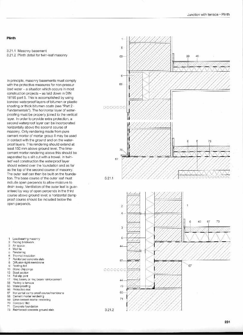
Plinth
3.21 .1 Masonry basement3.21 .2 Plinth detail for twin-leaf masonry
In principle, masonry basements must complywith the protective measures for non-pressur-ized waier - a situation which occurs in mostconstruction projects - as laid down in DIN18195 part 5. This is accomplished by usingbonded waterproof layers of bitumen or plasticsheeting or thick bitumen coats (see "Parl2.Fundamentals"). The horizontal layer of water-proofing must be properly joined to the verticallayer. In order to provide extra protection, asecond waterproof layer can be incorporatedhorizontally above the second course ofmasonry. Only rendering made from purecement mortar of mortar group ll may be usedin contact with the ground and on the water-proof layers. This rendering should extend atleast 150 mm above ground level. The lime-cement mortar rendering above this should beseparated by.a slit cut with a trowel, ln twin-leaf wall construction the waterproof layershould extend over the foundation and as faras the top ofthe second course of masonry.The outer leaf can then be built on the founda-tion. The base course of the outer leaf mustinclude open perpends to allow mojsture todrain away. Ventilation of the outer leaf is guar-anteed by way of open perpends in the thirdcourse above ground level; a horizontal dampproof course should be included below then n o n n o r n a n r l c
1 Loadbearing masonry2 Facing brickwork3 Air space4 Wall tie5 Rendering6 Thermal insulation7 Reinforced concrete slab8 Diffusion{ightmembraneI Roofing felt
10 Stone chippings13 Steel section14 Foil slip joint17 Ring beam, or ring beam reinforcement58 Paving to terrace65 Waterproofing66 Protective mat67 Horizontal damp proof course/membrane68 Cement mortar rendering69 Lime-cement mortar rendering70 Concave fillet71 Concrete foundation73 Reinforced concrete ground slab
oooooo
J , Z t , I
ooooo
3 .21 .2
231
Construction details
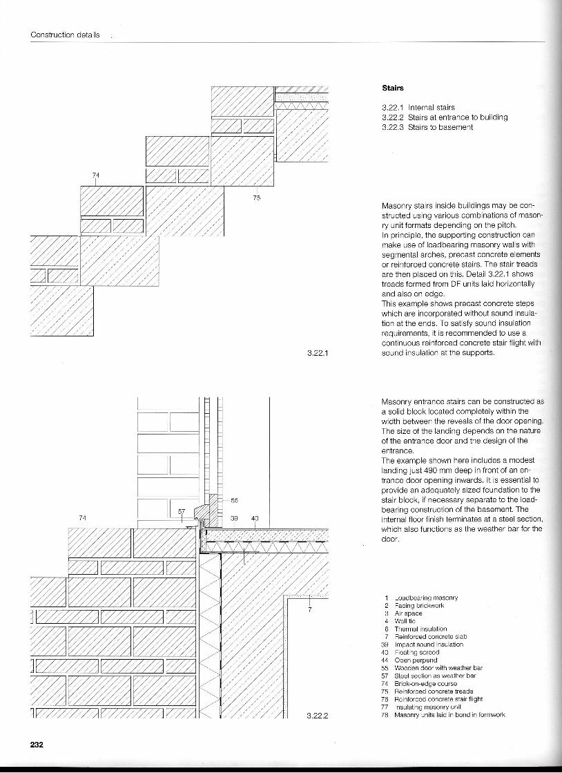
Stairs
3.22.1 Internal stairs3.22.2 Stairs at entrance to building3.22.3 Stairs to basement
Masonry stairs inside buildings may be con-structed using various combinations of mason-ry unit formats depending on the pitch.ln principle, the supporting construction canmake use of loadbearing masonry walls withsegmental arches, precast concrete elementsor reinforced concrete stairs. The stair treadsare then placed on this. Detail 3.22.1 showstreads formed from DF units laid horizontallvand also on edge.This example shows precast concrete stepswhich are incorporated without sound insula-tion at the ends. To satisfy sound insulationrequirements, it is recommended to use acontinuous reinforced concrete stair flight with
3.22.1 sound insulation at the supports.
Masonry entrance stairs can be constructed asa solid block located completely within thewidth between the reveals of the door opening.The size of the landing depends on the natureof the entrance door and the design of theentrance.The examole shown here includes a modestIanding just 490 mm deep in front of an en-trance door opening inwards. lt is essential toprovide an adequately sized foundation to thestair block, if necessary separate to the load-bearing construction of the basement. Theinternal floor finish terminates at a steel section,which also functions as the weather bar for theooor.
1 Loadbearing masonry2 Facingbrickwork3 Air space4 Wall tie6 Thermal insulation7 Reinforced concrete slab
39 lmpact sound insulation40 Floating screed44 Openperpend55 Wooden door with weather bar57 Steel section as weather bar74 Brick-on-edgecourse75 Reinforced concrete treads76 Reinforced concrete stair flight77 Insulating masonry unit78 lvlasonry units laid in bond in formwork
232
Stairs ' Re-entrant corner
f-
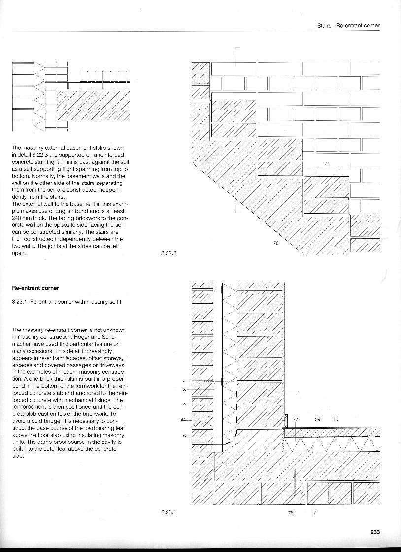
The masonry external basement stairs shownin detail 3.22.3 are supported on a reinforcedconcrete stair flight. This is cast against the soilas a self-supporting flight spanning from top tobottom. Normally, the basement walls and thewall on the other side of the stairs separatingthem from the soil are constructed indeoen-dently from the stairs.The external wall to the basement in this exam-ple makes use of English bond and is at least240 mm thick. The facing brickwork to the con-crete wall on the opposite side facing the soilcan be constructed similarly. The stairs arethen constructed independently between thetwo walls. The joints at the sides can be leftopen. 3.22.3
Re-entrant corner
3.23.1 Re-entrant corner with masonrv soffit
The masonry re-entrant corner is not unknownin masonry construction. Hoger and Schu-macher have used this oarticular feature onmany occasions. This detail increasinglyappears in re-entrant facades, offset storeys,arcades and covered passages or drivewaysin the examples of modern masonry construc-tion. A one-brick-thick skin is built in a properbond in the botiom of the formwork for the rein-forced concrete slab and anchored to the rein-forced concrete with mechanical fixings. Thereinforcement is then positioned and the con-crete slab cast on top of the brickwork. Toavoid a cold bridge, it is necessary to con-struct the base course of the loadbearing leafabove the floor slab using insulating masonryunits. The damp proof course in the cavity isbuilt into the outer leaf above the concreteslab.
EEEENEI
EEEEI
3.23.1
Construction details
3.23.2
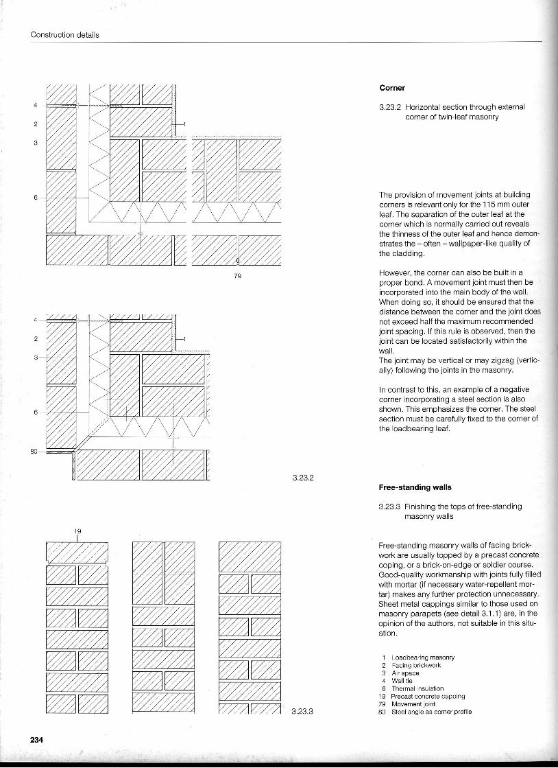
Corner
3.23.2 Horizontal section through externalcorner of twin-leaf masonry
The provision of movement joints at buildingcorners is relevant only for the 115 mm outerleaf. The separation of the outer leaf at thecorner which is normally carried out revealsthe thinness of the outer leaf and hence demon-strates the - often - wallpaper-like quality ofthe cladding.
However, the corner can also be built in aproper bond. A movement joint must then beincorporated into the main body of the wall,When doing so, it should be ensured that thedistance between the corner and the joint doesnot exceed half the maximum recommendedjoint spacing. lf this rule is observed, then thejoint can be located satisfactorily within thewall.The joint may be vertical or may zigzag (veriic-ally) following the joints in the masonry.
In contrast to this, an example of a negativecorner incorporating a steel section is alsoshown. This emphasizes the corner. The steelsection must be carefully fixed to the corner ofthe loadbearing leaf.
Free-standing walls
3.23.3 Finishing the tops of free-standingmasonry walls
Free-standing masonry walls of facing brick-work are usually topped by a precast concretecoping, or a brick-on-edge or soldier course.Good-quality workmanship with joints fully f i l ledwith mortar (if necessary water-repellent mor-tar) makes any further protection unnecessary.Sheet metal cappings similar to those used onmasonry parapets (see detail 3.1.1) are, in theopinion of the authors, not suitable in this situ-ation.
Loadbearing masonryFacing brickworkAir spaceWall tieThermal insulationPrecast concrete cappingMovement jointSteel angle as corner profile
12J
4o
1 97980
24
3.23.3