Embed Size (px)
Citation preview
Masonry Bases for the Installation of Microscopes and Their Accessories, including theCamera Lucida and the Microscope CameraAuthor(s): N. A. CobbSource: Transactions of the American Microscopical Society, Vol. 35, No. 1 (Jan., 1916), pp. 7-22Published by: Wiley on behalf of American Microscopical SocietyStable URL: http://www.jstor.org/stable/3221523 .
Accessed: 16/05/2014 19:41
Your use of the JSTOR archive indicates your acceptance of the Terms & Conditions of Use, available at .http://www.jstor.org/page/info/about/policies/terms.jsp
.JSTOR is a not-for-profit service that helps scholars, researchers, and students discover, use, and build upon a wide range ofcontent in a trusted digital archive. We use information technology and tools to increase productivity and facilitate new formsof scholarship. For more information about JSTOR, please contact [email protected].
.
Wiley and American Microscopical Society are collaborating with JSTOR to digitize, preserve and extendaccess to Transactions of the American Microscopical Society.
http://www.jstor.org
This content downloaded from 193.105.154.16 on Fri, 16 May 2014 19:41:56 PMAll use subject to JSTOR Terms and Conditions
TRANSACTIONS OF
American Microscopical Society (Published in Quarterly Installments)
Vol. XXXV JANUARY, 1916 No 1
MASONRY BASES FOR THE INSTALLATION OF MICRO- SCOPES AND THEIR ACCESSORIES, INCLUD-
ING THE CAMERA LUCIDA AND THE MICROSCOPE CAMERA
BY N. A. COBB
MASONRY AS A BASE
It has long been customary in the best laboratories to mount instruments of precision upon heavy pillars having foundations located in wells in the ground and passing upward through the floors without contact, the object being to prevent the tremors of the building from being transmitted to the instruments. The earth receives and nullifies the tremors.
The microscope has not often* received such special attention, notwithstanding the fact that whenever high powers are used, and
especially when photomicrographs or high power camera lucida
drawings are being prepared, vibration is objectionable. For many years I have had microscopes mounted on solid bases and strongly favor this method of support.
THE USE OF GIRDERS
One such installation was carried out in cement and steel as shown in Fig. 1.** Three girders, two approximately eight inches in each transverse dimension, and between them a third smaller one,
*The author knows of only about twenty of the massive installations such as are described in the following pages.
**The illustrations were made under the personal supervision of the author by Mr. E. M. Grosse and Mr. W. E. Chambers. They show so much detail, so nearly to scale, that any good mechanic can build from them.
This content downloaded from 193.105.154.16 on Fri, 16 May 2014 19:41:56 PMAll use subject to JSTOR Terms and Conditions
N. A. COBB
are imbedded vertically to the depth of several feet in a block of cement weighing many tons located under the building. The middle short girder, extending 18 inches above the floor, carries the microscope and certain accessories connected with illumination. The two tall, paired girders extend to within eighteen inches of the ceiling, projecting upward into the room about eleven feet. The wooden floor was laid tightly about the girders after they had been set in the cement and everything was then given a few months in which to settle into permanent position, after which an ordinary key-hole saw was run through the floor entirely around the contour of each girder, so that each cleared the flooring and floor-covering by the thickness of a saw blade. See 3, 43, etc., Fig. 1.
The girders, which clear the wall of the room by an inch or two, carry the accessory apparatus, which is attached to them in some instances by means of sliding one-sixteenth-inch sheet-metal sleeves that may be clamped at any desired height, in other instances by other means. All parts are dead black. The sleeve of the small central pillar projects outward at the top, that is, toward the observer, so as to form a microscope shelf one to two times larger than the base of the microscope. The sleeve carrying the micro- scope is clamped to its pillar by set-screws, and can be set high or low to suit different operators and different classes of work. When photographing it is better to set the microscope near the floor, so as to bring the camera (19, Fig. 1) low enough to make it unneces- sary to use a step-ladder in focusing. By placing the microscope high and the drawing table low, one can obtain for camera lucida work a distance of two and one-half feet between the level of the eye-piece of the microscope and that of the drawing table.
The sleeve carrying the microscope carries also a large vertical wooden front, two feet wide and as long as the microscope window is wide. This wooden front or screen slides up and down with the microscope, and has in it two apertures, one in front of the microscope mirror, designed to allow light from the sky, or from an illuminating screen, to strike the mirror and pass thence through the microscope; and the second to secure a correct illumination of the drawing board when the camera lucida is in use. See Fig. 1. This latter aperture is much the larger, is glazed with ground
8
This content downloaded from 193.105.154.16 on Fri, 16 May 2014 19:41:56 PMAll use subject to JSTOR Terms and Conditions
MASONRY BASES FOR MICROSCOPES
glass, and is opened and closed at will by means of a light, sus- pended, opaque slide worked up and down by foot-power.
The microscope window faces the sun, and is fitted with two light-proof roller blinds, one just behind the other, so that the sun's light may be shut off or allowed full access. The roller blinds move in lateral grooves ten inches deep, a depth sufficient to pre- vent the blinds from troubling by bellying on windy days. As a further provision against wind action, tight wires may be strung horizontally on the window frame inside the blinds. The blinds may be of any opaque material, and if long, should be thin. Ordi- nary opaque window blinds can be sized black so as to become prac- tically light-proof, and since it is advisable to have two blinds, such sizing wholly excludes the light. Ordinary spring rollers are used and are boxed in at the top in a light-tight manner.
CARRIERS FOR THE ACCESSORIES
The right-hand lower sleeve carries a leg-of-mutton shaped shelf or table for use in making camera lucida drawings. The sleeve, like all the other supports is balanced with a sash-weight, so as to move freely up or down through a range of several feet. The shape of the shelf has been evolved from years of use, and gives the investigator free play for hands and body. See 33, 34, Fig. 1.
At the left is a similar sleeve and shelf used for a different purpose,-although, as it is the mate to the camera lucida table, it could, in the case of a left-handed operator, be used as the right- hand table would be used by a right-handed operator. The usual position for the left-hand shelf is, however, about on a level with the microscope stage; first, because that is about ordinary table height and is convenient for supporting the dissecting microscope, which has a special illumination of its own (See Fig. 1); and sec- ond, because preparations may then be moved on and off the stage of the microscope with the least danger and with the greatest facility; a third reason is that in this position the left forearm finds it a most convenient rest in working the fine adjustment screw of the microscope, as shown in Fig. 3.
9
This content downloaded from 193.105.154.16 on Fri, 16 May 2014 19:41:56 PMAll use subject to JSTOR Terms and Conditions
N. A. COBB
The two long girders also carry two strong vertically adjust- able cross-pieces for the attachment of accessories above the micro- scope. Set-screws are provided for clamping the cross-pieces. Arms extend upward from the cross-pieces to carry anti-friction pulleys travelling on edges of the pillar. The microscope camera
(See 19, Fig. 1,) hangs above the microscope in readiness for instant use, and is of vertical pattern, carrying the photographic plate in a horizontal position. In focusing, the cross-piece carry- ing the camera is moved upward or downward; a scale on the pillars gives the various magnifications. The operator loosens two hooks and the camera front drops instantly into position on the end of the microscope barrel. The whole is ready for use in a few sec- onds' time. If the exposure is long, one leaves the instrument during the exposure with the greatest confidence that nothing can disturb it; tremors in the building will not be received either by the microscope or the photographic plate.
CAMERA LUCIDA
A second attachment of prime importance in producing illus- trations is the peculiar camera lucida. Fig. 1, 17, 24.
The history of the camera lucida is a very interesting one. It is impossible to go into details here, but nothing is clearer than that this instrument is one of great importance to the microscopist, and its history is in accordance with this fact. The utmost ingenuity has been exercised to produce an instrument by means of which sketches of small objects can be made with the aid of the micro- scope. The necessity for this class of work is very great. The photographic camera is inadequate for most objects. Only in the case of smears or exceedingly thin sections, or natural objects of great thinness, is a photomicrograph satisfactory. In all other cases, in order fully to elucidate the structure by means of an illus- tration, it is necessary to represent the appearances at different depths in the preparation. This can be done only by focusing the microscope for each particular depth. This fact, thus hastily explained, is what makes it absolutely necessary to use a camera lucida for the proper representation of most microscopic objects. This fundamental necessity is what has given rise to the many
10
This content downloaded from 193.105.154.16 on Fri, 16 May 2014 19:41:56 PMAll use subject to JSTOR Terms and Conditions
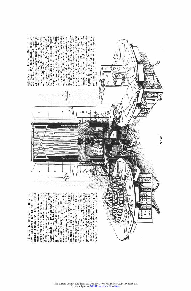
FIG. 1.-1, sash-cord pulleys; 2, steel sash-cords for 12 and 21; 3, girders perforating floor without contact; 4, same cords as 2; 5, frame- work from girder to girder; 6, upper opaque wooden sashes to side win- dows; 7, sash-weights balancing 12 and 21; 8, one of the 2 light-proof roller-blinds; 9, 10, anti-friction roll- er-bearing arms, bolted to 12 and 21; 11, 14, lower opaque wooden sashes; 12, cross-piece bearing camera 18, and camera-lucida prism 24; 13, screw-clamp to 12; 15, slot in which slides camera-lucida arm 17; 16, clamp to 21; 17, arm supporting cam- era-lucida prism 24; 18, ordinary camera attached to 12; 19, micro- scope camera attached to 21; 20, ad- justable headrest; 21, cross-arm sup- porting 19, 20 and drop-slide 32; 22, battery of microscope-barrels using direct sky light; 23, clamp to 21; 24, 45? camera-lucida prism; 25, 34, ad- justable, sliding, drawing board hung on cord and weight similar to 7; 26, headrest; 27, wide thin metal cur-
. 6I
16 - 3 1. -
~7
9
14
15
17
1.i444
tain-stick to inside roller-bind 8; 28, ways for thin metal slide 29, which has diamond-shaped opening 31; 30, small camera-lucida prism of usual pattern; 31, opening in 29, shown as being behind 32; 32, thin opaque adjustable drop-slide run by foot power 40, 41, 42; 33, adjustable leg-of-mutton shaped shelf; 34, mate to 33; 35, dark cloth enclosing micro- scope sub-stage; 36, aperture glazed
* . with ground glass in front of which 32 slides up and down; 37, steel ad-
' j justable sleeve carrying microscope i'. lon girder 38; 38, microscope girder
perforating floor without contact, im- t v * bedded in same cement block as 3; ' 39, floor aperture; 40, spring-roller
, foot power, sand-paper covered (41) controlling 32 by means of string and pulley 42; 42, deep-grooved pulley for string, controlling 32 by means of unseen pulley on back of 21; the
* , weight of 32 exactly counteracts the spring in 41; 43, girder, same as 3; 44, steel sleeve sliding on 43, sup- porting 33; 45, mate to 44, support- ing 25, 34.
PLATE I
w
I
This content downloaded from 193.105.154.16 on Fri, 16 May 2014 19:41:56 PMAll use subject to JSTOR Terms and Conditions
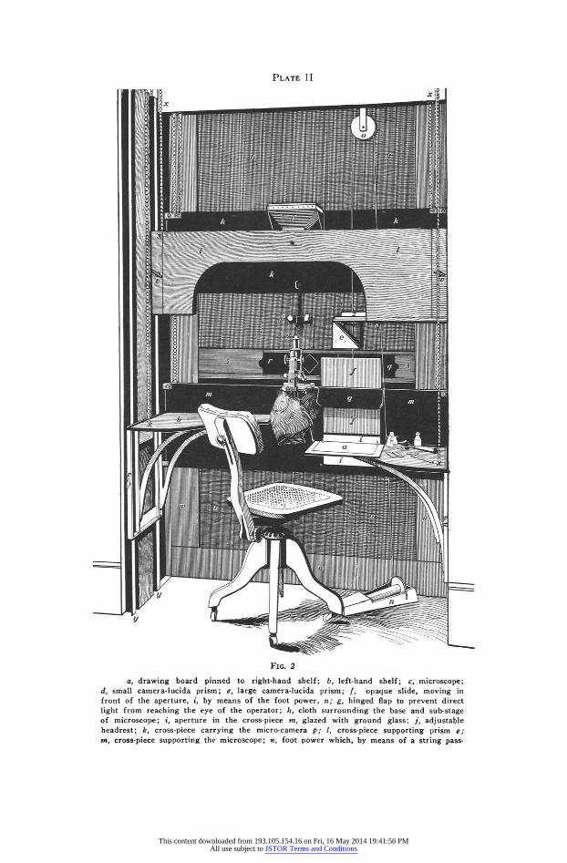
PLATE II
I
FIG. 2
FIG. 2
a, drawing board pinned to right-hand shelf; b, left-hand shelf; c, microscope; d, small camera-lucida prism; e, large camera-lucida prism; f, opaque slide, moving in front of the aperture, i, by means of the foot power, n; g, hinged flap to prevent direct light from reaching the eye of the operator; h, cloth surrounding the base and sub-stage of microscope; i, aperture in the cross-piece m, glazed with ground glass; j, adjustable headrest; k, cross-piece carrying the micro-camera p; 1, cross-piece supporting prism e; mn, cross-piece supporting the microscope; n, foot power which, by means of a string pass-
This content downloaded from 193.105.154.16 on Fri, 16 May 2014 19:41:56 PMAll use subject to JSTOR Terms and Conditions
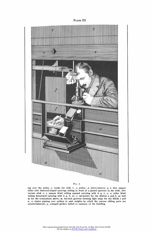
PLATE III
FIG. 3
ing over the pulley o, works the slide f, o, pulley; p, micro-camera; q, r, thin opaque slides with diamond-shaped openings sliding in front of a glazed aperture in the wide, thin curtain stick s; t, opaque blind rolling upward carrying with it q, r, s; u, roller blind rolling downward carrying with it g, h, m; v, set-screws for the shelves a and b, as well as for the cross-pieces above; w, ten-inch grooves forming light traps for the blinds t and u; x, chains passing over pulleys to sash weights by which the various sliding parts are counterbalanced; y, z-shaped girders bolted to masonry of the building.
This content downloaded from 193.105.154.16 on Fri, 16 May 2014 19:41:56 PMAll use subject to JSTOR Terms and Conditions
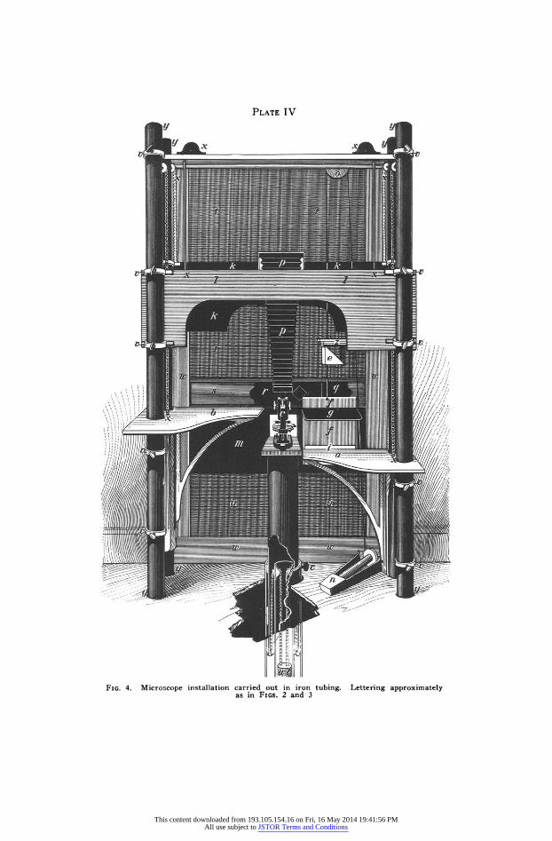
PLATE TV
.,,/ I
i ,/,.
FIG. 4. Microscope installation carried out in iron tubing. Lettering approximately as in FIGS. 2 and 3
This content downloaded from 193.105.154.16 on Fri, 16 May 2014 19:41:56 PMAll use subject to JSTOR Terms and Conditions
MASONRY BASES FOR MICROSCOPES
patterns which the camera lucida has taken on during its develop- ment. The first instiument was an extremely simple one. From time to time improvewments and additions have been made until at the present time the instrimentq issued by the best makers are marvels of ingenuity and workmanship. In fact, in the writer's opinion, they are almost too ingenious, for it appears to him that the various additions instrument-makers have made to the eamera lucida during recent years, while they do accotmplish the object aimed at, do so in an unsatisfactory manner.
To produce a good camera lucida drawing, it is necessary to have such light passing through the microscope as will enable the operator to see the object with the greatest possible dearness; and it is equally necessary so to control the light from the drawing board as to enable him to see his pencil-point at all times with the greatest possible clearness. With most objects it is impossible to secure this adjustment once for all, and for all portions of the drawing. Different portions of the object transmit or reflect differ- ent amounts of light, and, as this light varies it is necessary, in order that the drawing may be made with the greatest ease and precision, that the light from the drawing board should be modified accord- ingly. This end has been sought in a variety of ways, and more than any other one thing the effort to achieve this end has added to the complexity of the modern camera lucida. When the modem instrument is in good order, it may, it must be admitted, in a way accomplish its object; the difficulty is that it is complex and easily thrown out of adjustment, and some of its parts easily become soiled and dusty so as to be a hindrance rather than a help. Again, no very suitable device has yet been furnished by manufacturers for modifying the light from the drawing paper, except by a series of steps. It is usual to interpose tinted glasses, until the right balance of light has been secured, but it often happens that the most desirable shade cannot be secured, and in any case by this method there is always being inserted between the object and the eye, or the pencil and the eye, or between both and the eye, various pieces of apparatus that must be regarded as necessary evils, objectionable from a number of points of view.
11
This content downloaded from 193.105.154.16 on Fri, 16 May 2014 19:41:56 PMAll use subject to JSTOR Terms and Conditions
N. A. COBB
A second defect presented by many camera lucidas is the "double" reflection due to a silvered glass mirror. This defect can be tolerated for a short time, but after several hours the double reflection of the pencil point becomes very tiresome to the eye.
Any form of camera lucida hitherto introduced is trying to the eye-sight. During many years of experience the writer has endeavored to reduce the risk of injury to eye-sight due to use of the camera lucida, and the following suggestions, embodied in the outfits here described, are the result of his experiments. First, he has substituted for the ordinary mirror a large, and therefore neces- sarily heavy, 45 degree glass prism mounted on a support separate from the microscope. (24, Fig. 1 and e Figs. 2, 3 and 4). The ad- vantages of this substitution are: 1. As the prism is mounted sep- arately, it may be of any desired size, and may be placed at a considerable distance from the eye-piece of the microscope, thus increasing the magnification of the drawing; the advisability of this increased magnification will be dwelt upon later. 2. There are no double or multiple images and less light is lost by reflec- tion. The light passes from the drawing-point through the lower, i. e. horizontal face of the prism in a nearly perpendicular direction with little loss. It is then "totally" reflected from the oblique face, again with very little loss. 3. A third advantage of considerable importance is the stability of the apparatus; it rarely gets out of register. Forty-five degree prisms are made in about three qual- ities. The most perfectly corrected ones are very expensive; the second or even third grade prisms of the best manufacturers are suitable for camera lucida work.
ILLUMINATION OF THE DRAWING-PAPER
The second modification is that referred to on a previous page as the suspended slide or blind worked by foot-power. (Fig. 1, 32 and f Figs. 2, 3 and 4). This slide enables the operator to illuminate the drawing with almost any degree of light at an instant's notice without disturbing the adjustment of any part of the microscope or camera lucida.. This is highly important in the rapid production of good camera lucida sketches. Especially with high powers, the light coming through
12
This content downloaded from 193.105.154.16 on Fri, 16 May 2014 19:41:56 PMAll use subject to JSTOR Terms and Conditions
MASONRY BASES FOR MICROSCOPES
the microscope is often so faint that it is only by almost completely shutting off the light from the drawing, that the investi- gator can see at the same time both his pencil and the details of the structures to be sketched. With the foot-power arrangement the operator modifies the light in a second without disturbing the position of his body or his drawing-point, and instantly brings about that adjustment which is most favorable for any particular part of the sketch. Briefly, we may say that the operator's left arm rests on the left-hand "leg-of-mutton" shaped table on a level with the fine adjustment of the microscope, with his left hand in position to work the fine adjustment screw with the greatest ease and accuracy. His right hand, carrying the drawing-point, rests on the drawing board and is engaged in producing the sketch. As the light required for the different portions of the sketch varies he can effect the necessary change in illumination of the drawing paper by a slight movement of his right foot, which disturbs neither his hands nor the equilibrium of the instruments.
METHOD OF TRACING CAMERA-LUCIDA DRAWINGS
As will be at once conceded by any one who makes a trial, black paper is best adapted for camera lucida drawing; a white drawing point should be used. This is an improvement over a pencil used on white paper. The best combination is a thin black tissue-paper, blued on the under side by rubbing on dry prussian blue powder. A piece of drawing paper or enameled board of suitable size for the drawing is pinned to the drawing board,-i. e., the right-hand leg-of-mutton shaped table,-and is then covered with the black tissue-paper, blue side down, pinned at its back edge only. The sketch, a blue tracing, is now made with a fine white ivory or bone point. This blue sketch is put aside for further reference, or for the production of a finished drawing later on, or it may be inked in at once. The object aimed at is a satisfactory representation of the object to be illustrated, of sufficient size to admit of liberal reduction when the ink drawing is photographed on metal preparatory to etching. If it is desired to publish an illustration having a magnification of say 250 diameters, it is ad- visable to produce a blue sketch of at least 1,000 to 2,000 diameters.
13
This content downloaded from 193.105.154.16 on Fri, 16 May 2014 19:41:56 PMAll use subject to JSTOR Terms and Conditions
N. A. COBB
Highly magnified sketches are easily obtained with the apparatus just described, for by placing the prism reflector at a considerable horizontal distance from the eye-piece of the microscope, say one foot, and lowering the right-hand leg-of-mutton shaped table, mag- nifications of 5,000 diameters and upward are easily secured. Not infrequently the production of a large coarse drawing is an easier matter than the production of the same drawing on a smaller scale. The conversion of the blue sketch into a pen and ink drawing pre- sents no special peculiarities, but perhaps it ought to be mentioned that the object of using blue is to avoid trouble arising from altera- tions that may become necessary in finishing the drawing. Any light blue lines which are left on the drawing paper need not be removed, as they do not affect the photographic film sufficiently to cause any inconvenience in the production of an etched block. The black tissue paper mentioned is produced by inking ordinary tissue. The ordinary blue carbon paper gives too dark a blue to meet the requirements. A good quality of blue tracing paper may be made from black typewriter carbon-paper that has been exhausted by the typewriter,-the blue powder being rubbed onto the clean side of the carbon paper.
DARKENING THE ROOM CONTAINING THE INSTALLATION
In addition to blackening all accessories, arrangements are made to darken the room itself, in fact, to make it convertible into a photographic dark-room at will. All the window-blind connections are light-tight. The oblong aperture, about five inches by eight inches, through which the microscope mirror receives its light is screened by means of several thicknesses of flexible black cloth made into the form of a sleeve. This cloth sleeve, attached to the perimeter of the beveled aperture, is slit above and made to surround the microscope just beneath the stage, and the margins overlap and button to one of the screws at the back of the microscope; the low- er part of the microscope is thus located within the sleeve. No light reaches the observer's eye except that which comes through the instrument.
14
This content downloaded from 193.105.154.16 on Fri, 16 May 2014 19:41:56 PMAll use subject to JSTOR Terms and Conditions
MASONRY BASES FOR MICROSCOPES
If, now, the slide in front of the large glazed aperture be closed and all direct light shut out, the operator sits in darkness. Any one who has had experience with a photographic dark-room must have observed how after a period of from five to ten minutes there- in the eye becomes accustomed to the darkness of the room and is able to distinguish objects much more readily than at first. This is a principle which can be utilized to advantage in connection with high-power microscope work. In fact, it appears to be the relation between the external and the internal illumination which leads so many operators to use artificial light, and even in some cases to prefer working in the evening. If the surrounding light is dim and the eye is allowed to adjust itself to this dimness, then on look- ing through the properly adjusted microscope, certain details may be seen more clearly than in any other way. It is sometimes painful to witness the unconscious efforts of microscopists to bring about this condition as fully as possible by means of awkward atti- tudes and facial expression. It is not at all uncommon to see the microscope placed in a glare with strong light beating on the top of the preparation being examined and thence reflected confusingly up through the microscope, and to see the operator sitting in a cramped position, bending his head over the top of the instrument so as to shade his eye-piece as much as possible, and thus prevent eye-piece reflections. All this painful effort is simply an attempt to give the eye the benefit of a weak extraneous light and to pre- vent confusing reflections from the top of the mount and the eye- piece. With the apparatus here described these difficulties are minimized. The room is darkened. All light which could reach the operator's eye is excluded, except that which comes through the microscope. There is no light falling upon the top of the object, to cause confusing reflections inside the microscope, nor can rays of light be thrown into the eye from the top of the eye- piece, or from high lights on the stand. The image to be examined is as clear as it can be made and the eye is given every facility to see it, and is distracted by no others.
The advantages of this system of using a microscope are not confined to high-powers. It is well known that the central portions of microscope lenses act more perfectly than the peripheral portions.
15
This content downloaded from 193.105.154.16 on Fri, 16 May 2014 19:41:56 PMAll use subject to JSTOR Terms and Conditions
N. A. COBB
By shutting out these latter, better optical results are secured, but the illumination is considerably diminished. The low degree of illumination is less objectionable when the observer is in darkness or semi-darkness. I believe this is due to some extent to relaxa- tion of the iris muscles.
It might at first be thought that this would result in a less per- fect image on the retina of the eye, and no doubt this is true if we consider the entire image on the retina. The fact is, however, that the observer concentrates his attention upon a small portion of the retina image and this portion may be focused as accurately as his
eye admits. In respect to perfection of image, a comparison of the human eye to an ordinary camera may be very misleading.
CAMERA-LUCIDA DRAWINGS OF DIFFICULT OPAQUE OBJECTS
Camera lucida drawings of opaque objects present numerous difficulties, prominent among which is the small amount of light coming through the microscope. By illuminating the object with a strong light, sunlight if necessary, and reducing to a minimum the amount of light coming from the drawing paper, it is not at all difficult with this apparatus to produce satisfactory drawings of these difficult objects.
Needless to say the apparatus is a daylight apparatus. It hardly seems necessary to argue that as daylight is the light that has developed the human eye it is probably the light to which it is best adapted. This seems a sufficient argument for the use of daylight and a sufficient explanation of its superiority to every other light for the average run of microscopic work. Using the installations here described, monochromatic light of superlative quality is easily obtained by interposing colored glasses or liquids. However, when all this is said, it is not possible always to secure and control day- light so as to get the best results. The following contrivances are such as experience has shown to be very useful for this purpose, especially in sunny climates.
SOURCE OF LIGHT FOR THE MICROSCOPE
Outside of the microscope window a universally adjustable three-by-five-foot white screen is placed in a sunny position, prefer- ably about ten feet away. The surface of this screen should be
16
This content downloaded from 193.105.154.16 on Fri, 16 May 2014 19:41:56 PMAll use subject to JSTOR Terms and Conditions
MASONRY BASES FOR MICROSCOPES
smooth but not shiny and may be of any fine-grained white material. It can be made of wood, painted white, or lined with plaster of Paris; or, what is better, be a plain wooden screen covered with sheet metal and over all several thicknesses of bleached cotton cloth. Whitewash makes a cheap and very excellent white surface for this purpose, and may be applied over cloth. If a small mirror be attached to one corner of the screen, it will indicate the position of the screen that will reflect to the microscope a maximum of white light. Place the screen so that the flash of sunlight from the mirror strikes in the vicinity of the microscope; then the whole screen will be in corresponding position and reflect a maximum of light to the microscope. It is better if this screen can be adjusted from the interior of the microscope room, but this is not essential. After the screen is set the light from it remains for an hour or more practically constant, so that while an adjustment by cords or other mechanism from the interior is a convenience, it is not a necessity. If an adjustable screen is not available it may be possible to arrange two fixed screens, one screen for morning and the other for afternoon.
Blue sky is not a satisfactory source of light. A white cloud gives a very good light, but clouds are so changeable that it is not wise to rely upon them. It is therefore much preferable to con- struct, as described, an adjustable white screen that will be avail- able whenever the sun shines. When the sun does not shine the sky may serve, or if the day is too dull, one resorts to artificial light.
MICROSCOPE INSTALLATION BOLTED TO THE MASONRY OF
THE BUILDING
The installation just described can be bolted to the masonry of the building by means of small vertical I-shaped or Z-shaped girders as shown in Fig. 2. The installation is in most respects similar to that just described, except that the microscope is carried on a heavy cast-iron cross-piece, m, sliding up and down on a pair of L-shaped or Z-shaped girders, and carrying with it an opaque roller blind, u, which passes around a roller at the bottom of the window near the floor.
17
This content downloaded from 193.105.154.16 on Fri, 16 May 2014 19:41:56 PMAll use subject to JSTOR Terms and Conditions
N. A. COBB
In Fig. 2, a number of details are more dearly shown than in Fig. 1, for instance, the details of the headrest, j, which consists of two oblique cork-covered pads, one circular, the other square, each carried on a horizontal screw so that they can be rotated and at the same time moved inward or outward. These pads screw into a cross-piece, which in turn is fastened securely to a vertical rod which slides up and down and rotates, and is clamped by the set-screw shown near k. The great adjustability of these pads makes it easy to fit them to the head of any operator. They serve to keep the observer's eye in register, as well as to decrease fatigue, and actually improve his observing power.
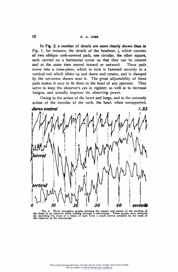
Owing to the action of the heart and lungs, and to the unsteady action of the muscles of the neck, the head, when unsupported,
dorso-venftl X 35 jIt ! zi _ . , Ai A X ! , g /i A h .
7 1 10 20 1 30 40 seconds t FIG. 5. Three successive graphs showing the nature and extent of the motions of
the head of an observer while looking through a microscope. These graphs were obtained by recording the trace of a beam of light from a small mirror actuated by the head of the observer at the microscope.
18
This content downloaded from 193.105.154.16 on Fri, 16 May 2014 19:41:56 PMAll use subject to JSTOR Terms and Conditions
MASONRY BASES FOR MICROSCOPES
is in constant motion, and the image of any stationary object formed meanwhile on the retina of the eye is moving in a corresponding way. The movements of the microscopist's head are shown in the accompanying three graphs (Fig. 5). Both the nature and extent of the rotations about three coordinate axes, at right angles to each other, are shown at a magnification of 35 diameters. These graphs were obtained by recording the trace of a beam of light reflected from a small mirror actuated by the head of the, observer at the microscope. The smallest motions indicated in the graphs, a, a, a, are due to the action of the heart; each tiny irreg- ularity represents a heart-beat. The larger irregularities, such as those shown at b, b, b, are due to lung action; the head rises and falls with each breath. Moreover, these two irregularities, those due to the heart's action and those due to the action of the lungs, are distributed on a great curve, which I suppose to be a curve of fatigue connected with the action of the muscles of the neck. These graphs show how complicated are the movements of the image on the retina. Keenness of vision is a function, among other things, of the steadiness of the retina. This is a matter of personal ex- perience, but arguments in favor of a steady retina may be sug- gested somewhat as follows: It is a matter of common observation that all organisms possessing well-developed eyes, hold the head as steady as possible when looking intently. If while reading from a printed page one wags the head perceptibly, even at so slow a rate as that of the heart's beat, vision is very considerably im- paired; the less of this motion, the keener the vision. What is the limit of this improvement in vision due to increased steadiness of the retina? Theoretically it would seem to be reached when the retina is absolutely steady. When we consider the minuteness of the elements in the retina having to do with vision,-the rods and cones and other elements-it seems a very reasonable sup- position that vision can be increased in keenness beyond the degree attained by holding the head as steadily as possible by means of the cervical muscles. Whether these arguments are valid or not, the writer is convinced, from years of experience with mechanical headrests, that their use adds to the acuteness of vision. More- over, they diminish fatigue, making it possible for the observer
19
This content downloaded from 193.105.154.16 on Fri, 16 May 2014 19:41:56 PMAll use subject to JSTOR Terms and Conditions
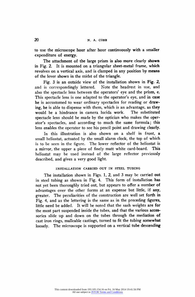
N. A. COBB
to use the microscope hour after hour continuously with a smaller expenditure of energy.
The attachment of the large prism is also more clearly shown in Fig. 2. It is mounted on a triangular sheet-metal frame, which revolves on a vertical axis, and is clamped in any position by means of the lever shown in the midst of the triangle.
Fig. 3 is an outside view of the installation shown in Fig. 2, and is correspondingly lettered. Note the headrest in use, and also the spectacle lens between the operators' eye and the prism, e. This spectacle lens is one adapted to the operator's eye, and in case he is accustomed to wear ordinary spectacles for reading or draw-
ing, he is able to dispense with them, which is an advantage, as they would be a hindrance in camera lucida work. The substituted spectacle lens should be made by the optician who makes the oper- ator's spectacles, and according to much the same formula; this lens enables the operator to see his pencil point and drawing clearly.
In this illustration is also shown on a shelf in front, a small heliostat, actuated by the small alarm clock, the top of which is to be seen in the figure. The lower reflector of the heliostat is a mirror, the upper a piece of finely matt white card-board. This heliostat may be used instead of the large reflector previously described, and gives a very good light.
INSTALLATION CARRIED OUT IN STEEL TUBING
The installation shown in Figs. 1, 2, and 3 may be carried out in steel tubing as shown in Fig. 4. This form of installation has not yet been thoroughly tried out, but appears to offer a number of advantages over the other forms at an expense but little, if any, greater. The peculiarities of the construction are well set forth in
Fig. 4, and as the lettering is the same as in the preceding figures, little need be added. It will be noted that the sash weights are for the most part suspended inside the tubes, and that the various acces- sories slide up and down on the tubes through the mediation of cast iron rings, malleable castings, turned to fit the tubing somewhat loosely. The microscope is supported on a vertical tube descending
20
This content downloaded from 193.105.154.16 on Fri, 16 May 2014 19:41:56 PMAll use subject to JSTOR Terms and Conditions
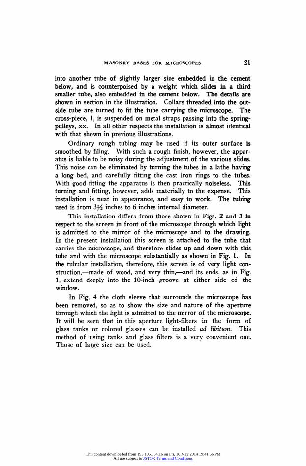
MASONRY BASES FOR MICROSCOPES
into another tube of slightly larger size embedded in the cement below, and is counterpoised by a weight which slides in a third smaller tube, also embedded in the cement below. The details are shown in section in the illustration. Collars threaded into the out- side tube are turned to fit the tube carrying the microscope. The cross-piece, 1, is suspended on metal straps passing into the spring- pulleys, xx. In all other respects the installation is almost identical with that shown in previous illustrations.
Ordinary rough tubing may be used if its outer surface is smoothed by filing. With such a rough finish, however, the appar- atus is liable to be noisy during the adjustment of the various slides. This noise can be eliminated by turning the tubes in a lathe having a long bed, and carefully fitting the cast iron rings to the tubes. With good fitting the apparatus is then practically noiseless. This turning and fitting, however, adds materially to the expense. This installation is neat in appearance, and easy to work. The tubing used is from 3Y2 inches to 6 inches internal diameter.
This installation differs from those shown in Figs. 2 and 3 in respect to the screen in front of the microscope through which light is admitted to the mirror of the microscope and to the drawing. In the present installation this screen is attached to the tube that carries the microscope, and therefore slides up and down with this tube and with the microscope substantially as shown in Fig. 1. In the tubular installation, therefore, this screen is of very light con- struction,-made of wood, and very thin,-and its ends, as in Fig. 1, extend deeply into the 10-inch groove at either side of the window.
In Fig. 4 the cloth sleeve that surrounds the microscope has been removed, so as to show the size and nature of the aperture through which the light is admitted to the mirror of the microscope. It will be seen that in this aperture light-filters in the form of glass tanks or colored glasses can be installed ad libitum. This method of using tanks and glass filters is a very convenient one. Those of large size can be used.
21
This content downloaded from 193.105.154.16 on Fri, 16 May 2014 19:41:56 PMAll use subject to JSTOR Terms and Conditions

22 N. A. COBB
The shelf at the top of the installation, carrying the spring- pulleys, x, x, and clamped in position by the higher set-screws, v, v, and supporting the pulley, o, has for its main object to keep the four cylindrical pillars in register,-that is, parallel to one another,- and to prevent vibration.
This content downloaded from 193.105.154.16 on Fri, 16 May 2014 19:41:56 PMAll use subject to JSTOR Terms and Conditions