Embed Size (px)
Citation preview

-1-
-
MASHANTUCKET PEQUOT
UTILITIES DEPARTMENT
Sewer Specifications and Requirements
-2-
-
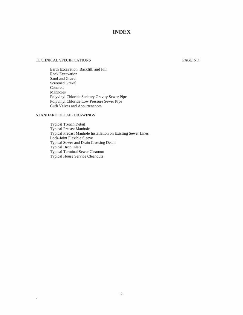
INDEX
TECHNICAL SPECIFICATIONS PAGE NO.
Earth Excavation, Backfill, and Fill
Rock Excavation
Sand and Gravel
Screened Gravel
Concrete
Manholes
Polyvinyl Chloride Sanitary Gravity Sewer Pipe
Polyvinyl Chloride Low Pressure Sewer Pipe
Curb Valves and Appurtenances
STANDARD DETAIL DRAWINGS
Typical Trench Detail
Typical Precast Manhole
Typical Precast Manhole Installation on Existing Sewer Lines
Lock-Joint Flexible Sleeve
Typical Sewer and Drain Crossing Detail
Typical Drop Inlets
Typical Terminal Sewer Cleanout
Typical House Service Cleanouts
-1-
-
EXCAVATION, BACKFILL AND FILL
1. SEPARATION OF SURFACE MATERIALS
The Contractor shall remove only as much of any existing pavement as is necessary for the prosecution of the work.
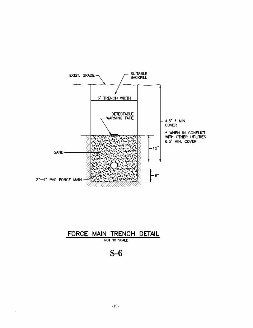
2. WIDTH OF TRENCH
Pipe trenches shall be as narrow as practicable and shall not be widened by scraping or loosening materials from the
sides. Every effort shall be made to keep the sides of the trenches firm and undisturbed until backfilling has been
completed and consolidated.
Trenches shall be excavated with approximately vertical sides between the elevation of the center of the pipe and an
elevation 1 ft. above the top of the pipe.
3. TRENCH EXCAVATION
Where pipe is to be laid in crushed stone bedding, the trench may be excavated by machinery to, or to just below,
the designated subgrade, provided that the material remaining at the bottom of the trench is no more than slightly
disturbed.
4. UNAUTHORIZED EXCAVATION
If the bottom of any excavation is taken out beyond the limits indicated or prescribed, the resulting void shall be
backfilled with thoroughly compacted, screened gravel, if the excavation was for a pipeline, or with concrete, if the
excavation was for a masonry structure.
5. EXCAVATION NEAR EXISTING STRUCTURES
Attention is directed to the fact that there are pipes, drains, and other utilities in certain locations.
As the excavation approaches pipes, conduits, or other underground structures, digging by machinery shall be
discontinued and the excavation shall be done by means of hand tools. Such manual excavation when incidental to
normal excavation shall be included in the work to be done under items involving normal excavation.
Where determination of the exact location of pipe or other underground structure is necessary for doing the work
properly, the Contractor may be required to excavate test pits to determine such locations.
6. ELIMINATION OF UNSUITABLE MATERIAL
If material unsuitable for foundation is found at or below the grade to which excavation would normally be carried,
the Contractor shall remove such material to the required width and depth and replace it with thoroughly compacted,
screened gravel or concrete as directed.
7. SHEETING AND SHORING
The Contractor shall be responsible for supporting and maintaining excavations required hereunder, even to the
extent of sheeting or shoring the sides and ends of excavations with timber or steel sheet piling. The requirements of
sheeting or shoring or the addition of supports shall not relieve the Contractor of his responsibility for their sufficiency.
All timbering shall be removed except that for the purpose of preventing injury to the piping or other structures, to
other property or to persons.
-2-
-
8. REMOVAL OF WATER
Until final acceptance of the work, the Contractor shall pump out or otherwise remove and dispose of as fast as it
may collect, any water, sewage or other liquids which may be found or may accumulate in the excavations, regardless of
whether it be water or liquid wastes from his own contract or from any existing conduits, works, or surface runoff.
There shall be upon the work at all times during the construction, proper and approved machinery of sufficient
capacity (including spare units kept ready for immediate use in case of breakdowns) to meet the maximum requirements
for the removal of the water or other liquids and their disposal in such a manner as not to withdraw sand or cement from
the concrete and so as not to interfere with the proper laying of pipe and/or masonry or the prosecution of work under
this or other contract nor endanger existing structures.
9. PROTECTION TO EXISTING STRUCTURES, VEGETATION
All existing walks, pipes, conduits, poles, wires, fences, stairways, curbings, property line markers, walls, buildings
and other structures which do not require to be changed in location, shall be carefully supported and protected from
injury by the Contractor, and in case of injury, they shall be restored by him to as good condition as that in which they
were found.
10. BACKFILLING PIPE TRENCHES
As soon as practicable after the pipes have been laid or the structures have been built and are structurally adequate to
support the loads, including construction loads to which they will be subjected, the backfilling shall be started and
thereafter it shall proceed until completion.
a. Zone Around Pipe. The space between the pipe and bottom side of the trench shall be packed full by hand
shovel with sand. In placing the material, care shall be taken that stones do not strike the pipe. The backfill under the
pipe shall be thoroughly compacted using curved tamping bars. Sand backfill at the sides and up to the top of the pipe
shall be compacted using approved hand tampers. Sand backfill up to a level of 1 ft. above the top of the pipe shall be
placed in 6-in. layers, leveled along with the length and width of the trench, and thoroughly compacted using approved
tampers. No sand shall be placed above the top of the pipe until sand under and at the sides of the pipe has been
compacted. Care shall be taken in the use of mechanical or other tampers not to injure or move the pipe or to cause the
pipe to be supported unevenly.
b. Materials. The nature of the materials will govern both their acceptability for backfill and the methods best
suited for their placement and compaction in the backfill. In general, material used for backfilling trenches and
excavations around structures shall be suitable materials which was removed in the course of making the construction
excavations.
No stone or rock fragment larger than 12 in. in greatest dimension shall be placed in the backfill nor shall
large masses of backfill material be dropped into the trench in such a manner as to endanger the pipeline. If necessary, a
timber grillage shall be used to break the fall of material dropped from a height of more than 5 ft. Pieces of bituminous
pavement shall be excluded from the backfill unless their use is expressly permitted, in which case they shall be broken
up as directed.
c. Remainder of Trench. The remainder of the trench above the zone around the pipe shall be compacted by
tamping as directed or approved in accordance with the nature of the material.
-3-
-
d. Tamping. Compaction shall be accomplished by tamping, or under appropriate circumstances, rolling. The
material shall be deposited and spread in uniform, parallel layers not exceeding 8 in. thick before compaction. Before
the next layer is placed, each layer shall be tamped as required so as to obtain a thoroughly compacted mass. If
necessary, the Contractor shall furnish and use an adequate number of power driven tampers, each weighing at least 20
lbs., for this purpose. Care shall be taken that the material close to the bank, as well as in all other portions of the trench,
is thoroughly compacted. When the trench width and the depth to which backfill has been placed are sufficient to make
it feasible, and it can be done effectively and without damage to the pipe, backfill may, on approval, be compacted by the
use of suitable rollers, tractors, or similar powered equipment instead of tamping. For compaction by tamping (or
rolling), the rate at which backfilling material is deposited in the trench shall not exceed that permitted by the facilities
for its spreading, leveling, and compacting as furnished by the Contractor.
If necessary to ensure proper compaction by tamping (or rolling), the material shall first be wet by
sprinkling. However, no compaction by tamping (or rolling) shall be done when the material is too wet either from rain
or too great an application of water to be compacted properly; at such times the work shall be suspended until the
previously placed and new materials have dried out sufficiently to permit proper compacting, or such other precautions
shall be taken as may be necessary to obtain proper compaction.
e. Miscellaneous Requirements. Whatever method of compacting backfill is used, care shall be taken that
stones and lumps shall not become nested and that all voids between stones shall be completely filled with fine material.
Only approved quantities of stones and rock fragments shall be used in the backfill. The Contractor shall, as part of the
work done under the times involving earth excavation and rock excavation as appropriate, furnish and place all other
necessary backfill material.
11. FILL AND BACKFILL UNDER STRUCTURES AND ROADS
All fill and backfill under structures and pavements adjacent to structures shall be compacted bank-run gravel
containing not more than 5% passing a 200 sieve. The entire backfill shall be compacted to 95% of maximum density at
optimum moisture as determined by Method “D” of ASTM D1557-78 Standard Test Methods for Moisture-Density
Relations of Soils and Soil-Aggregate Mixtures Using 10lb. (4.54-kg) Rammer and 18 in. (457mm) Drop.
ROCK EXCAVATION
1. WORK INCLUDED
The Contractor shall excavate within the lines and grades as shown or required and shall satisfactorily dispose of
any rock, boulders, or existing concrete, stone or masonry which may be encountered in the work.
The word “rock” shall mean boulders and pieces of masonry or concrete exceeding one cubic yard in volume, or
solid ledge rock which in the opinion of the Engineer requires for its removal, drilling and blasting or wedging, or
sledging, or barring, or breaking up with a power operated tool. No soft or disintegrated rock which can be removed
with a hand pick or power operated excavator or shovel; no loose, shaken or previously blasted rock or broken stone in
rock fillings or elsewhere; and no rock, exterior to the minimum limits allowed, which may fall into the excavation will
be allowed.
2. BLASTING AND EXPLOSIVES
Where blasting is necessary, it shall be done in accordance with all ordinances and other pertinent regulations. Such
ordinances, regulations and orders shall not, however, relieve the Contractor of any responsibility for damages caused by
him or his employees.
-4-
-
SAND AND GRAVEL
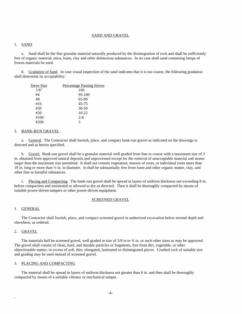
1. SAND
a. Sand shall be the fine granular material naturally produced by the disintegration of rock and shall be sufficiently
free of organic material, mica, loam, clay and other deleterious substances. In no case shall sand containing lumps of
frozen materials be used.
b. Gradation of Sand. In case visual inspection of the sand indicates that it is too coarse, the following gradation
shall determine its acceptability:
Sieve Size Percentage Passing Sieves
3/8” 100
#4 95-100
#8 65-90
#16 45-75
#30 30-50
#50 10-22
#100 2-8
#200 3
2. BANK-RUN GRAVEL
a. General. The Contractor shall furnish, place, and compact bank-run gravel as indicated on the drawings or
directed and as herein specified.
b. Gravel. Bank-run gravel shall be a granular material well graded from fine to coarse with a maximum size of 3
in. obtained from approved natural deposits and unprocessed except for the removal of unacceptable material and stones
larger than the maximum size permitted. It shall not contain vegetation, masses of roots, or individual roots more than
18 in. long or more than ½ in. in diameter. It shall be substantially free from loam and other organic matter, clay, and
other fine or harmful substances.
c. Placing and Compacting. The bank-run gravel shall be spread in layers of uniform thickness not exceeding 8 in.
before compaction and moistened or allowed to dry as directed. Then it shall be thoroughly compacted by means of
suitable power-driven tampers or other power-driven equipment.
SCREENED GRAVEL
1. GENERAL
The Contractor shall furnish, place, and compact screened gravel in authorized excavation below normal depth and
elsewhere, as ordered.
2. GRAVEL
The materials hall be screened gravel, well graded in size of 3/8 in to ¾ in. or such other sizes as may be approved.
The gravel shall consist of clean, hard, and durable particles or fragments, free from dirt, vegetable, or other
objectionable matter, in excess of soft, thin, elongated, laminated or disintegrated pieces. Crushed rock of suitable size
and grading may be used instead of screened gravel.
3. PLACING AND COMPACTING
The material shall be spread in layers of uniform thickness not greater than 6 in. and then shall be thoroughly
compacted by means of a suitable vibrator or mechanical tamper.
-5-
-
CONCRETE
1. WORK INCLUDED
The Contractor shall furnish all labor, materials, tools and equipment necessary to construct the concrete work
required by this contract. This will include thrust blocks at pipe bends and tees in trenches, and for all miscellaneous
concrete work ordered in the field to meet field conditions.
2. MATERIALS
a. All materials are to be carefully selected so as to be free of deleterious amounts of acid, alkali and organic
material. If these materials are stored at the job they shall be placed where no foreign materials will be introduced and
no deterioration of the cement will take place. Latest revisions of A.S.T.M. Specifications are to be followed.
b. Portland Cement shall conform to A.S.T.M. C150-85a.
c. Aggregate shall conform to A.S.T.M. C33-86.
d. Reinforcing bars shall conform to A.S.T.M. A615-85 or A.S.T.M. A617-84, Grade 40.
3. CONCRETE QUALITY
Concrete shall have a minimum ultimate 28 days compressive strength of 3000 lbs. per square inch using a
maximum water content of 6 gallons per bag of cement. The aggregate shall be proportioned to give a dense concrete of
this required strength using a maximum aggregate size of ¾ inches.
Concrete for pavement replacement shall conform to the requirements of the State of Connecticut, Department of
Transportation.
4. MIXING AND PLACING
a. Concrete shall be mixed until there is a uniform distribution of the materials and shall be discharged completely
before the mixer is recharged.
b. For job-mixed concrete, the mixer shall be rotated at a speed recommended by the manufacturer, and mixing
shall be continued for at least one minute after all materials are in the mixer.
c. Ready-mixed concrete shall be mixed and delivered in accordance with the requirements set forth in the
standard specifications for Ready-Mixed Concrete A.S.T.M. c94-86a.
d. Provisions shall be made for maintaining concrete in a moist condition for at least 5 days after placement.
Concrete shall be protected against wash by ground water in ditches.
e. Adequate equipment shall be provided for protecting the concrete from freezing. No frozen material or
materials containing ice shall be used. No dependence shall be placed on salt or other chemicals for the prevention of
freezing.
f. Admixtures shall be in conformance with the recommendations and requirements of Form 813 and shall be
approved by the Engineer prior to use.

-6-
-
MANHOLES
1. GENERAL
The Contractor shall furnish all materials and shall construct all the manholes required including the frames, covers,
and steps.
2. DESCRIPTION
Manholes shall conform in shape, size, dimensions, materials, and other respects to the details indicated on the detail
drawing specifications, or as approved by the City.
Manholes may have cast in place concrete bases and may be precast units. Invert channels may be formed in the
concrete of the base or may be formed of brick and mortar upon the base.
Manhole barrels and domes shall be precast concrete sections. The top 8 in. shall be built of brick or concrete
grading rings to permit adjustment of the frame to meet the street surface. The inverts shall conform accurately to the
size of the adjoining pipes. Side inverts shall be curved and main inverts (where direction changes) shall be laid out in
smooth curves of the longest possible radius which is tangent to the centerlines of adjoining sewers.
3. PRECAST CONCRETE SECTIONS
Precast concrete sections shall conform to the A.S.T.M. Standard Specifications for Precast Reinforced Concrete
Manhole Sections, Designation C478-85a, with the following exceptions and additional requirements:
The barrel shall not be less than 5 in. thick.
Type II cement shall be used except as otherwise approved.
Joints between sections shall be made with round (0-ring) rubber gaskets with a shitable groove on the spigot ends
and shall conform to the A.S.T.M. Standard Specifications for Joints for Circular Concrete sewer and Culvert Pipe,
Using Rubber Gaskets, Designation C443-85a.
Manhole sections shall contain manhole steps accurately positioned and embedded in the concrete when the section
is cast.
Sections shall be cured by subjecting them to thoroughly saturated steam at a temperature between 100 and 130 deg.
F. for a period of not less than 12 hours or, when necessary, for such additional time as may be needed to enable the
section to meet the strength requirements.
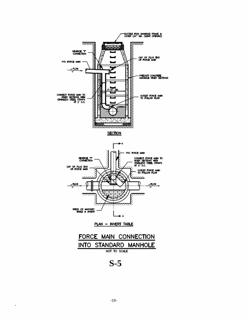
The joint for the pipe at the base section shall consist of a Lock Joint flexible sleeve (imbedded in the wall of the
base section) and a stainless steel strap to provide a water tight seal and allow a flexible joint. (Or Approved Equal)
No more than two lift holes may be cast or drilled in each section.
The date of the manufacture and the name or trademark of the manufacturer shall be clearly marked on the inside of
the barrel.
Acceptance of the sections will be on the basis of material tests and inspections of the completed product.
Cones shall be precast sections of the eccentric type.
If precast concrete sections are used, the tops of the bases shall be suitably shaped by means of accurate bell-ring
forms to receive the barrel sections.
-7-
-
4. SETTING PRECAST MANHOLE SECTIONS
Precast-reinforced concrete manhole sections shall be set so as to be vertical and with sections and steps in true
alignment.
Rubber gaskets shall be installed in all joints in accordance with the manufacturer’s recommendations.
All holes in the sections used for their handling shall be thoroughly plugged with rubber plugs made specifically for
this purpose or with mortar. The mortar shall be one part cement to 2 parts sand, mixed slightly damp to the touch (just
short of “balling), hammered into the holes until it is dense and an excess of past appears on the surface, and then
finished smooth and flush with the adjoining surfaces.
5. BRICK
The brick shall be sound, hard, and uniformly burned brick, regular and uniform in shape and size, of compact
texture, and satisfactory to the Engineer. Brick shall comply with the A.S.T.M. Standard Specification for Sewer Brick
and Manhole Brick (made from Clay or Shale) Designation C32-73 (Reapproved 1984) for Grade SS, hard brick, except
that the mean of five tests for absorption shall not exceed eight percent by weight.
Rejected brick shall be immediately removed from the work.
6. MORTAR FOR BRICKWORK
The mortar shall be composed of portland cement, hydrated lime, and sand, in which the volume of sand shall not
exceed three times the sum of the volumes of cement and lime. The proportions of cement and lime shall be as directed
and may vary from 1: ¼ for dense, hard-burned brick to 1:3/4 for softer brick. In general, mortar for Grade SS brick
shall be mixed in the proportions of 1: ½:4-1/2.
Cement shall be Type II portland cement as specified for concrete masonry.
7. LAYING BRICKWORK
Only clean bricks shall be used in brickwork for manholes. The brick shall be moistened by suitable means, as
directed, until they are neither so dry as to absorb water from the mortar nor so wet as to be slippery when laid. Each
brick shall be laid in a full bed and joint of mortar without requiring subsequent grouting, flushing, or filling, and shall
be thoroughly bonded as directed.
8. COATING
The exterior surfaces of all manholes shall be given two coats of bituminous waterproofing material. The material
shall be Minwax Fibrous Coat made by Minwax Co., New York, N.Y.; Tremco 121 Foundation Coating made by
Tremco Mfg. Co., Cleveland, Ohio; Inertol No. 7 made by the Inertol Co., Inc., Newark, N.J.; or approved equal product.
The waterproofing material shall be applied by brush or spray and in accordance with the instructions of the
manufacturer. Time shall be allowed between coats to permit sufficient drying so that the application of the second coat
has no effect on the first coat.
-8-
-
9. MANHOLE FRAMES AND COVERS
The Contractor shall furnish all cast-iron manhole frames and covers.
The cast-iron frames and covers shall be Pattern No. 1009 manufactured by the Campbell Foundry Co., Harrison,
N.J., or approved equal product.
The frames and covers shall be set by the Contractor to conform accurately to the grade of the finished pavement, or
existing ground surface.
The castings shall be of good quality, strong, tough, even-grained cast iron, smooth, free from scale, lumps, blisters,
sandholes, and defects of every nature which would render them unfit for the service for which they are intended.
Contact surfaces of covers and frame seats shall be machined to prevent rocking of covers. (4-5/8” vent holes min).
All castings shall be thoroughly cleaned and subject to a careful hammer inspection.
Castings shall be at least Class 30 conforming to the A.S.T.M. Standard Specification for Gray Iron Castings,
Designation A48-83.
Before being shipped from the foundry, castings shall be given one coat of coal-tar-pitch varnish, applied in a
satisfactory manner so as to make a smooth coating, tough, tenacious, and not brittle or with any tendency to scale off.
10. SETTING MANHOLE FRAMES AND COVERS
Manhole frames shall be set with the tops conforming accurately to the grade of the pavement or finished ground
surface or as indicated on the drawings or directed. Frames shall be set concentric with the top of the mansonry and in a
full bed of mortar so that the space between the top of the manhole masonry and the bottom flange of the frame shall be
completely filled and made watertight. A thick ring of mortar extending to the outer edge of the masonry shall be placed
around and on top of the bottom flange. The mortar shall be smoothly finished and have a slight slope to shed water
away from the frame.
Manhole covers shall be left in place in the frames on completion of other work at the manholes.
11. STUBS IN MANHOLES
Stubs placed as specified and indicated on the drawings shall extend into the manhole with sufficient clearance to
allow a standard joint to be made.
12. MANHOLE STEPS
Unless otherwise indicated, manhole steps shall be of aluminum. Aluminum manhole steps for precast concrete
sections shall be Stock No. 12653B made by Aluminum Company of America and Allegheny Foundry Co., or Stock No.
F-14-2B made by New Jersey Aluminum Co., or an approved equal product. Before the steps are built into the masonry
and after thorough cleaning, those parts of aluminum steps which will be embedded shall be given a protective coating of
an approved, heavy-bodied, bituminous material. The cleaning shall be done by suitable means with suitable cleaning
agents to ensure that the surfaces to be coated are free from all foreign matter such as dirt, oil, and grease. The steps
shall be thoroughly rinsed and dried before the coating is applied and the coating shall have become thoroughly dry
before the steps are built into the masonry.
-9-
-
POLYVINYL CHLORIDE SANITARY GRAVITY SEWER PIPE
1. GENERAL
The Contractor shall furnish, lay, joint and test the polyvinyl chloride sanitary sewer pipe, fittings and
appurtenances.
2. PIPE AND FITTINGS
Polyvinyl chloride sanitary sewer pipe shall be composed of clean, virgin class 12454-B PVC compounds according
to ASTM Standard Specifications, Designation D3034-85A. All pipe and fittings shall be SDR 35 heavy wall pipe
having bell and spigot with rubber ring joints as manufactured by Johns-Manville, Certainteed, or approved equal
product.
Joints for the pipe shall be of the integral bell type, consisting of an integral wall section with a solid cross section
rubber ring securely set in place to prevent dislocation of the ring.
The pipe shall be furnished in standard 20 foot and 12.5 foot laying lengths.
Minimum pipe stiffness at 5% deflection shall be 46 PSI for all sizes when tested in accordance with ASTM D2412-
77, Standard Test Method for External Loading Properties of Plastic Pipe by Parellel-Plate Loading.
3. HANDLING AND CUTTING PIPE
The Contractor’s attention is directed to the fact that polyvinyl chloride pipe and fittings used with the pipe are
comparatively brittle. Care shall be taken in handling and laying pipe and fittings to avoid damaging the pipe and
fittings.
Any fittings showing a crack, and any fitting or pipe which has received a severe blow that may have caused an
incipient fracture, even though no such fracture can be seen, shall be marked as rejected and removed at once from the
work.
Polyvinyl chloride pipe shall be cut by means of a hand saw, “metal inserted” abrasive wheels, or by plastic tubing
cutters with blades, not rollers, doing the cutting. All cut ends shall be examined for possible cracks caused by cutting.
All burrs from both the inside and outside of the pipe must be removed with a knife, file or reamer prior to jointing the
pipe.
4. JOINTING PIPE AND FITTINGS
Polyvinyl chloride sanitary sewer pipe and fittings shall be jointed in accordance with the latest detailed instructions
of the manufacturer.
The Contractor shall furnish coupling pullers for jointing the pipe. Gasket-feeler gauges shall be available for use
by the pipe layer and the Engineer for checking the position of the rubber gaskets in the completed joint.
1. LOW PRESSURE AIR TESTS
Tests shall be conducted on all sewers as soon after installation and partial backfill has been completed in a manner
and sequence as approved by the Engineer.
-10-
-
Equipment shall be Cherne Air-Loc Equipment as manufactured by Cherne Industrical, Inc., Edina, Minnesota, or
an approved equal. Equipment shall meet the following minimum requirements:
a. Pneumatic plugs shall have a sealing length equal to or greater than the diameter of the pipe to be tested.
b. Pneumatic plugs shall be able to resist internal test pressures without requiring external bracing or blocking.
c. All air used shall pass through a single control panel.
d. Three individual hoses shall be used for the following connections:
1. From control panel to pneumatic plugs for inflations.
2. From control panel to sealed line for introducing the low pressure air.
3. From sealed line to control panel for continually monitoring the air pressure rise in the sealed line.
2. PROCEDURES
All pneumatic plugs shall be seal tested before being used in the actual test installation. One length of pipe shall be
laid on the ground and sealed at both ends with the pneumatic plugs to be used in the testing. Air shall be introduced
into the plugs to 25 psig. The sealed pipe shall be pressurized to 10 psig. The plugs shall hold against the 10 psig
pressure without bracing and without movement of the plug.
After a manhole to manhole reach of pipe has been backfilled and cleaned, and the pneumatic plugs are checked by
the above procedure, the plugs shall be placed in the line at each manhole and inflated to 25 psig. Low pressure air shall
be introduced into the sealed line until the internal air pressure reaches 4 psig greater than the average back pressure of
any groundwater that may be over the pipe. At least two minutes shall be allowed for the air pressure to stabilize.
After the stabilization period (3.5 psig minimum pressure in the pipe), the air hose from the control panel to the air
supply shall be disconnected. The portion of the line being tested shall be termed “Acceptable” if the time required in
minutes for the pressure to decrease from 3.5 to 2.5 psig (greater than the average back pressure of any groundwater that
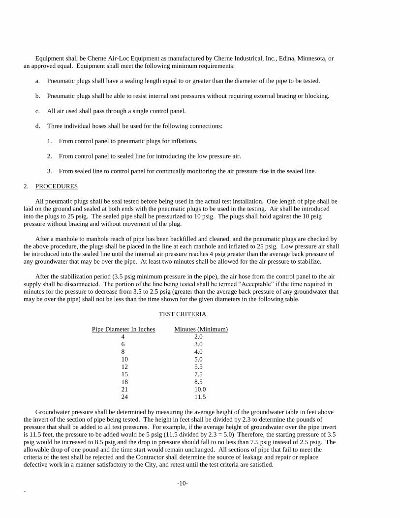
may be over the pipe) shall not be less than the time shown for the given diameters in the following table.
TEST CRITERIA
Pipe Diameter In Inches Minutes (Minimum)
4 2.0
6 3.0
8 4.0
10 5.0
12 5.5
15 7.5
18 8.5
21 10.0
24 11.5
Groundwater pressure shall be determined by measuring the average height of the groundwater table in feet above
the invert of the section of pipe being tested. The height in feet shall be divided by 2.3 to determine the pounds of
pressure that shall be added to all test pressures. For example, if the average height of groundwater over the pipe invert
is 11.5 feet, the pressure to be added would be 5 psig (11.5 divided by 2.3 = 5.0) Therefore, the starting pressure of 3.5
psig would be increased to 8.5 psig and the drop in pressure should fall to no less than 7.5 psig instead of 2.5 psig. The
allowable drop of one pound and the time start would remain unchanged. All sections of pipe that fail to meet the
criteria of the test shall be rejected and the Contractor shall determine the source of leakage and repair or replace
defective work in a manner satisfactory to the City, and retest until the test criteria are satisfied.
-11-
-
POLYVINYL CHLORIDE LOW PRESSURE SEWER PIPE
1. GENERAL
The Contractor shall furnish, lay, joint and test the polyvinyl chloride low pressure sewer pipe, fittings and
appurtenances.
2. PIPE AND FITTINGS
Polyvinyl chloride low pressure sewer pipe and fittings shall be Schedule 40, solvent weld pressure pipe conforming
to ASTM Standard Specifications, Designation D2241084 and D1784-81 and shall be of the sizes as indicated on the
drawings. The pipe and fittings shall be as manufactured by Johns-Manville, Certainteed, or approved equal product.
Fittings for solvent weld pressure pipe shall have a pressure rating not less than that of the pipe and be fully
compatible with the pipe supplied without alteration.
Joints for the pipe shall be solvent weld, polyvinyl chloride joints and shall be made in accordance with the
manufacturer’s recommendations or as directed by the Engineer.
The pipe shall be furnished in standard 20 foot laying lengths.
All fittings and bends a required shall be backed up with class B concrete thrust blocks as indicated on the drawings
or as directed by the Engineer.
3. HANDLING AND CUTTING PIPE
The Contractor’s attention is directed to the fact that polyvinyl chloride pipe and fittings used with the pipe are
comparatively brittle. Care shall be taken in handling and laying pipe and fittings to avoid damaging the pipe and
fittings.
Any fittings showing a crack, and any fitting or pipe which has received a severe blow that may have caused an
incipient fracture, even though no such fracture can be seen, shall be marked as rejected and removed at once from the
work.
Polyvinyl chloride pipe shall be cut by means of a hand saw, “metal-inserted” abrasive wheels, or by plastic tubing
cutters with blades, not rollers, doing the cutting. All cut ends shall be examined for possible cracks caused by cutting.
All burrs from both the inside and outside of the pipe must be removed with a knife, file or reamer prior to jointing the
pipe.
4. JOINTING PIPE AND FITTINGS
Polyvinyl chloride low pressure sewer pipe and fittings shall be jointed using solvent weld, polyvinyl chloride joints
in accordance with the latest detailed instructions of the manufacturer.
5. INSTALING PIPE AND FITTINGS
No defective pipe or fittings shall be installed. Any piece discovered to be defective after having been laid shall be
removed and replaced with a sound piece.
Each pipe and fitting shall be cleared of all debris, dirt, etc., before being installed and shall be kept clean until
accepted in the completed work.
Each length of pipe shall be shoved home against the pipe previously laid and held securely in position. Joints shall
not be “pulled” or “cramped” without approval of the Engineer.
-12-
-
Before any joint is made, the pipe shall be checked to assure that a close joint with the next adjoining pipe has been
maintained and that the inverts are matched and conform to the required grade. The pipe shall not be driven down to the
required grade by striking it.
Pipe or fittings shall not be left permanently supported on saddles or blocking, but shall be firmly supported by
screened gravel or sand as indicated on the drawings.
The screened gravel or sand shall be thoroughly compacted under the pipe so as to obrain a substantial unyielding
bed shaped as indicated on the drawings. After each pipe has been properly bedded, enough screened gravel or sand
shall be placed between the pipe and the sides of the trench, and thoroughly compacted, to hold the pipe in correct
alignment. Holes provided for jointing shall be filled and compacted and then screened gravel or sand shall be placed
and compacted to complete the bedding as indicated on the drawings.
Adjacent to structure walls, the pipe shall be provided with a concrete cradle as indicated on the details. Class B
Concrete shall be used, or if the Contractor prefers, Class A concrete for the structure base may be extended to the
cradles.
The Contractor shall take all necessary precautions to prevent flotation of the pipe in the trench.
Hydrated lime shall be Type S conforming to the ASTM Standard Specifications for Hydrated Lime for Masonry
Purposes, Designation C207-79 (Reapproved 1984).
The sand shall comply with the specifications for “Fine Aggregate” for concrete masonry except that all of the sand
shall pass a No. 8 sieve.
6. TEMPORARY PLUGS
When pipe laying is not in progress, the open ends of the pipe shall be closed with temporary watertight plugs. If
water is in the trench when work is resumed, the plug shall not be removed until all danger of water entering the pipe is
eliminated.
Pipelines shall not be used as conductors for trench drainage during construction.
Leakage tests shall be conducted by maintaining the pipe under a pressure, as measured at the point of lowest
elevation, of 50 pounds per square inch for at least 2 hours. Care should be taken to expel all air from the pipes when
filling with water. The quantity of water measured to maintain the test pressure shall not exceed 0.009 gallons per inch
of diameter per 24 hours per joint. If the leakage exceeds this rate, the Contractor must repair, replace or relay sections
of pipe and repeat the tests until satisfactory to the Engineer.
-13-
-
CURB VALVES AND APPURTENANCES
1. GENERAL
The Contractor shall furnish all curb valves and appurtenances as indicated on the drawings and as herein specified.
2. CURB VALVES AND APPURTENANCES
Curb valves shall be Mueller Oriseal Model H-10291 or be approved equal.
Cast iron valve box including lid and plug, footpiece and stationary rod shall be Mueller Model H-10386 or an
approved equal. The work “sewer” shall be cast on the cover. The length of the valve box shall be as necessary to suit
the ground elevation.
-14-
-
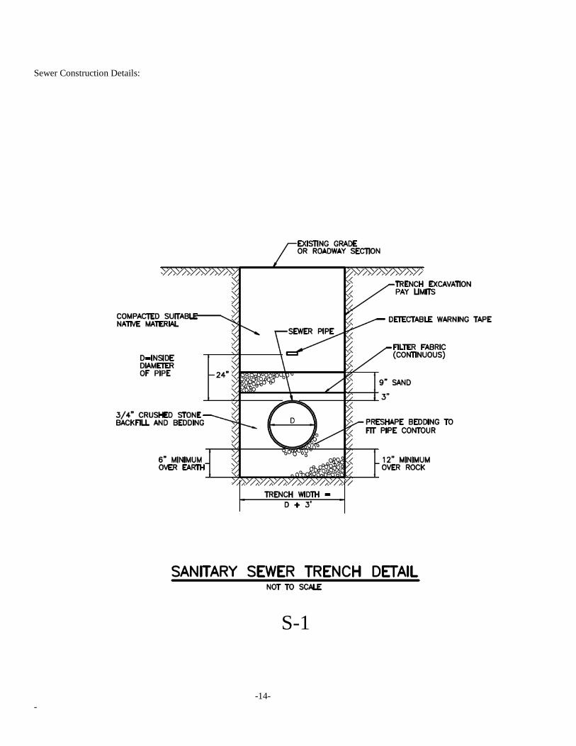
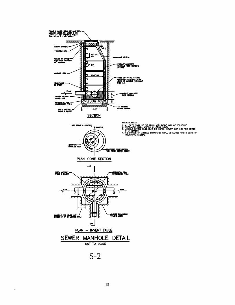
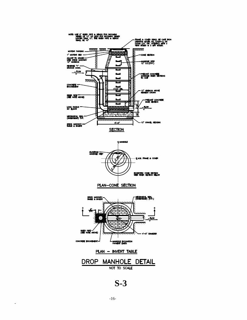
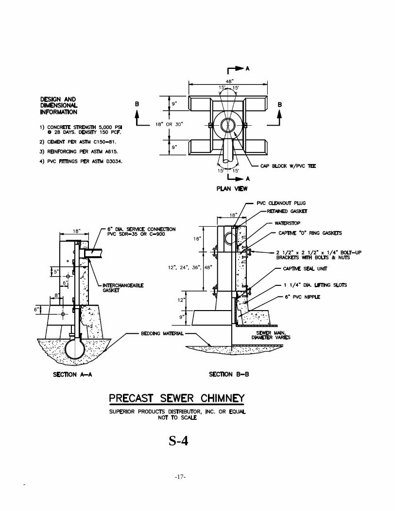
Sewer Construction Details:
S-1
-15-
-
S-2
-16-
-
S-3
-17-
-
S-4
-18-
-
S-5
-19-
-
S-6